Stacked sections are zero offset sections • Because of the distortions due to structure, and diffractions, stack sections only approximate the true subsurface • Distortion can be extreme in structurally complex areas • Solution is “seismic migration” (topic of the next lecture(s)) Model Events on stack section
Transcript
Stacked sections are zero offset sections
• Because of the distortions due to structure, and diffractions, stack sections only approximate the true subsurface
• Distortion can be extreme in structurally complex areas
• Solution is “seismic migration” (topic of the next lecture(s))
Model
Events on stack section
Introduction to seismic migration
• Even for a simple, dipping reflector the reflection appears in the wrong place on the stack section
• Examination of the figure shows that
1. Events on the stack section appear vertically below midpoints; true reflection points are further updip
2. The reflection has a gentler dip on the stack section than in reality
3. The reflection points are further apart on the stack section than they are in reality
Introduction to seismic migration
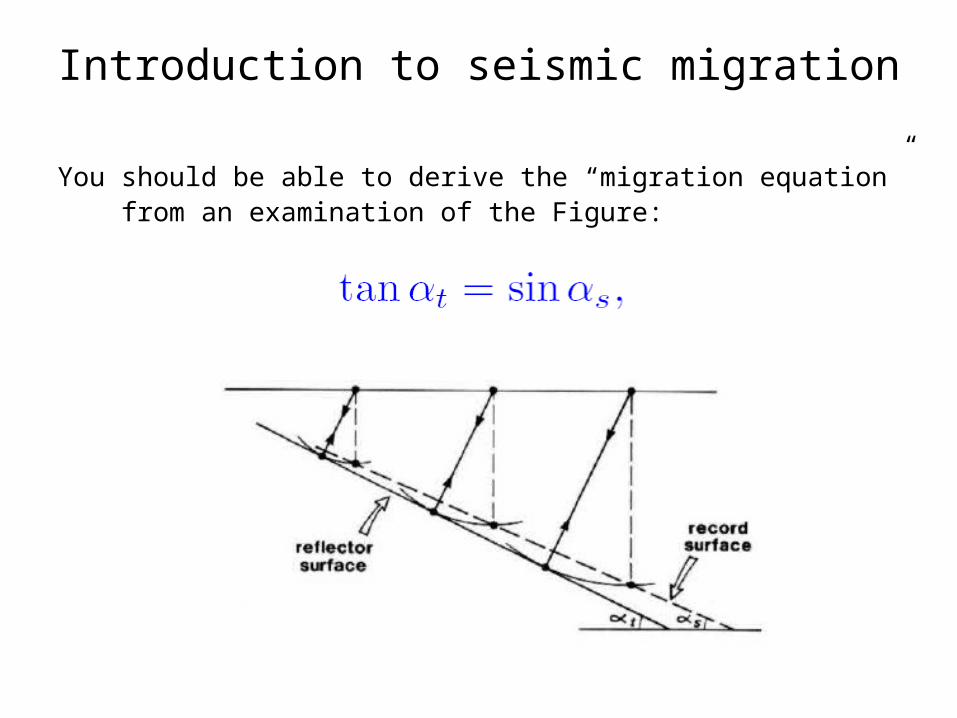
You should be able to derive the “migration equation” from an examination of the Figure:
Introduction to seismic migration
Introduction to seismic migration
Which of the two sections below is the original stack, and which is the migrated section?
Introduction to seismic migration
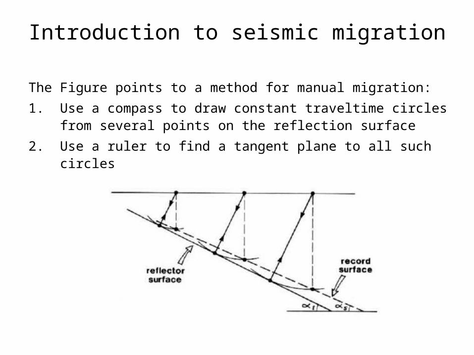
The Figure points to a method for manual migration:
1. Use a compass to draw constant traveltime circles from several points on the reflection surface
2. Use a ruler to find a tangent plane to all such circles
Introduction to seismic migration
Manual migration:
1. Use a compass to draw constant traveltime circles from several points on the reflection surface
2. Use a ruler to find a tangent plane to all such circles
• The strategy works equally well for migrating diffractions
• Constant traveltime circles all intersect at a point, corresponding to the true location of the discontinuity
Introduction to seismic migration
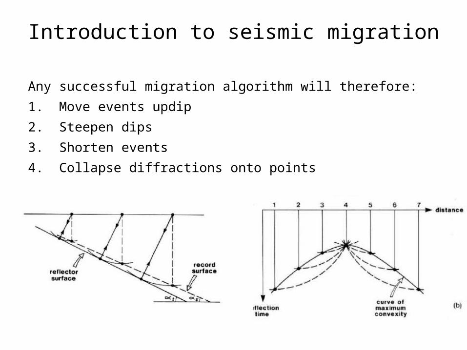
Any successful migration algorithm will therefore:
1. Move events updip
2. Steepen dips
3. Shorten events
4. Collapse diffractions onto points
Introduction to seismic migration
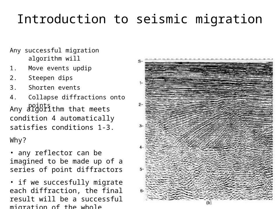
Any successful migration algorithm will
1. Move events updip
2. Steepen dips
3. Shorten events
4. Collapse diffractions onto points
Any algorithm that meets condition 4 automatically satisfies conditions 1-3.
Why?
• any reflector can be imagined to be made up of a series of point diffractors
• if we succesfully migrate each diffraction, the final result will be a successful migration of the whole reflector
Introduction to seismic migration
The “wavefront” method for seismic migration:
• every pixel on the section defines a traveltime
• the computer can generate a constant traveltime circle on the section
• constant traveltime curves are known as “wavefronts”
• the energy found at each pixel is distributed over the wavefront
• result is a coherent superposition where these wavefronts are tangent, or where they intersect
Introduction to seismic migration
The wavefront method corresponds to moving (“migrating”) energy along constant traveltime curves (“wavefronts”)
Introduction to seismic migration
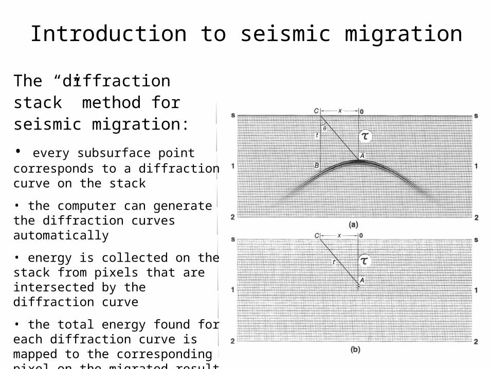
The “diffraction stack” method for seismic migration:
• every subsurface point corresponds to a diffraction curve on the stack
• the computer can generate the diffraction curves automatically
• energy is collected on the stack from pixels that are intersected by the diffraction curve
• the total energy found for each diffraction curve is mapped to the corresponding pixel on the migrated result
• result is that all diffractions are “stacked” into the correct location
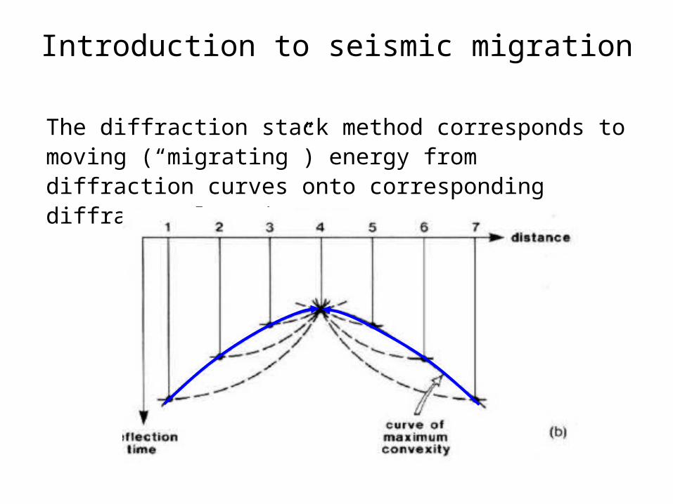
Introduction to seismic migration
The diffraction stack method corresponds to moving (“migrating”) energy from diffraction curves onto corresponding diffractor locations
Introduction to seismic migration
Both the wavefront method and the diffraction stack method are equivalent: both produce the same migrated section
Examples of seismic migration
Model with diffractions, anticlines, synclines
Examples of seismic migration
Example of “bowtie” associated with syncline
Examples of seismic migration
Example of “bowtie” associated with syncline
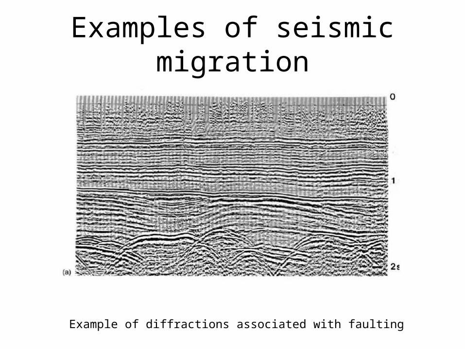
Examples of seismic migration
Example of diffractions associated with faulting
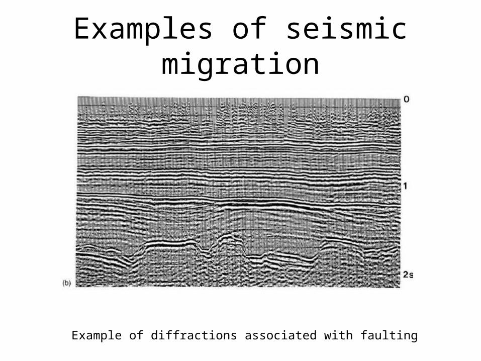
Examples of seismic migration
Example of diffractions associated with faulting
Examples of seismic migration
A, B are multiples
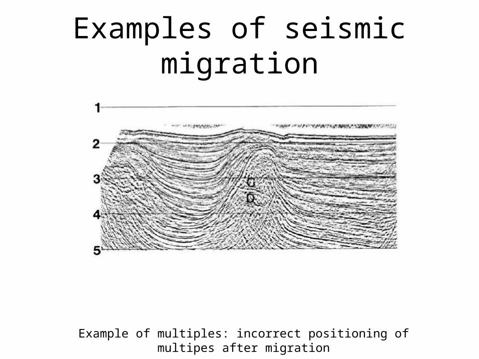
Examples of seismic migration
Example of multiples: incorrect positioning of multipes after migration