+ All Categories
Home > Documents > STEALTH Tech Report

STEALTH Tech Report

Date post: 08-Apr-2018
Category:
Upload: supreeth
View: 221 times
Download: 0 times
Share this document with a friend
20
STEALTH TECHNOLOGY Dept. of Mechanical Engineering CONTENTS: 1. History - - - - - - - - - - - - - - - - - - - - - - - - - - - - - - - - - - - - - - - - - - - -01 2. Introduction - - - - - - - - - - - - - - - - - - - - - - - - - - - - - - - - - - - - - - - 02 3. About radar - - - - - - - - - - - - - - - - - - - - - - - - - - - - - - - - - - - - - - - 03 4. Stealth principles- - - - - - - - - - - - - - - - - - - - - - - - - - - - - - - - - - - 05 4.1 Vehicle shape - - - - - - - - - - - - - - - - - - - - - - - - - - - - - - - - - - 05 4.2 Propulsion sub-system - - - - - - - - - - - - - - - - - - - - - - - - - - - - -05 4.3 Non-metallic air frame - - - - - - - - - - - - - - - - - - - - - - - - - - - - -05 4.4 Radar absorbing material - - - - - - - - - - - - - - - - - - - - - - - - - - - 06 5. Case study: F-117 Nighthawk - - - - - - - - - - - - - - - - - - - - - - - - -07 5.1 F-117 Nighthawk specs - - - - - - - - - - - - - - - - - - - - - - - - - - - - -07 5.2 Dimensions - - - - - - - - - - - - - - - - - - - - - - - - - - - - - - - - - - - - -08 5.3 Stealth implementation - - - - - - - - - - - - - - - - - - - - - - - - - - - - -08 5.4 Nighthawk engagement profile - - - - - - - - - - - - - - - - - - - - - - - 11 5.5 Retirement - - - - - - - - - - - - - - - - - - - - - - - - - - - - - - - - - - - - - 11 6. Advantages - - - - - - - - - - - - - - - - - - - - - - - - - - - - - - - - - - - - - - - - 13 7. Limitations - - - - - - - - - - - - - - - - - - - - - - - - - - - - - - - - - - - - - - - - -14 7.1 Instability of design - - - - - - - - - - - - - - - - - - - - - - - - - - - - - - - 14 7.2 Reduced payload - - - - - - - - - - - - - - - - - - - - - - - - - - - - - - - - - 14 7.3 Cost of operation - - - - - - - - - - - - - - - - - - - - - - - - - - - - - - - - -14 8. Measuring stealth - - - - - - - - - - - - - - - - - - - - - - - - - - - - - - - - - - - 16 9. Conclusion - - - - - - - - - - - - - - - - - - - - - - - - - - - - - - - - - - - - - - - - - 17 10.Reference - - - - - - - - - - - - - - - - - - - - - - - - - - - - - - - - - - - - - - - - - 18 1
Transcript

8/7/2019 STEALTH Tech Report

http://slidepdf.com/reader/full/stealth-tech-report 1/20

STEALTH TECHNOLOGY

Dept. of Mechanical Engineering

CONTENTS:

1. History - - - - - - - - - - - - - - - - - - - - - - - - - - - - - - - - - - - - - - - - - - - -01

2. Introduction - - - - - - - - - - - - - - - - - - - - - - - - - - - - - - - - - - - - - - - 02

3. About radar - - - - - - - - - - - - - - - - - - - - - - - - - - - - - - - - - - - - - - - 03

4. Stealth principles- - - - - - - - - - - - - - - - - - - - - - - - - - - - - - - - - - - 05

4.1 Vehicle shape - - - - - - - - - - - - - - - - - - - - - - - - - - - - - - - - - - 05

4.2 Propulsion sub-system - - - - - - - - - - - - - - - - - - - - - - - - - - - - -05

4.3 Non-metallic air frame - - - - - - - - - - - - - - - - - - - - - - - - - - - - -05

4.4 Radar absorbing material - - - - - - - - - - - - - - - - - - - - - - - - - - - 06

5. Case study: F-117 Nighthawk - - - - - - - - - - - - - - - - - - - - - - - - -07

5.1 F-117 Nighthawk specs - - - - - - - - - - - - - - - - - - - - - - - - - - - - -07

5.2 Dimensions - - - - - - - - - - - - - - - - - - - - - - - - - - - - - - - - - - - - -08

5.3 Stealth implementation - - - - - - - - - - - - - - - - - - - - - - - - - - - - -08

5.4 Nighthawk engagement profile - - - - - - - - - - - - - - - - - - - - - - - 11

5.5 Retirement - - - - - - - - - - - - - - - - - - - - - - - - - - - - - - - - - - - - - 11

6. Advantages - - - - - - - - - - - - - - - - - - - - - - - - - - - - - - - - - - - - - - - - 13

7. Limitations - - - - - - - - - - - - - - - - - - - - - - - - - - - - - - - - - - - - - - - - -14

7.1 Instability of design - - - - - - - - - - - - - - - - - - - - - - - - - - - - - - - 14

7.2 Reduced payload - - - - - - - - - - - - - - - - - - - - - - - - - - - - - - - - - 14

7.3 Cost of operation - - - - - - - - - - - - - - - - - - - - - - - - - - - - - - - - -14

8. Measuring stealth - - - - - - - - - - - - - - - - - - - - - - - - - - - - - - - - - - - 16

9. Conclusion - - - - - - - - - - - - - - - - - - - - - - - - - - - - - - - - - - - - - - - - - 17

10.Reference - - - - - - - - - - - - - - - - - - - - - - - - - - - - - - - - - - - - - - - - - 18

1

8/7/2019 STEALTH Tech Report

http://slidepdf.com/reader/full/stealth-tech-report 2/20

STEALTH TECHNOLOGY

Dept. of Mechanical Engineering

HISTORY

Almost since the invention of radar, various techniques have been tried to minimize

detection. Rapid development of radar during World War II led to equally rapid development

of numerous counter radar measures during the period; a notable example of this was the use

of chaff.

In the late 1950's the American, Central Intelligence Academy (CIA) began sending

Lockheed U-2 'spy-planes' over the Soviet Union to take intelligence photographs. The U-2's

were little more than jet-powered gliders built of plastic and plywood flew at 80,000ft

(24,000m) to be out of range of anti-aircraft fire, but it then became clear that radar was not

detecting them.

It was not until May 1960, after more than four years of over-flights, that the Russians shot

one down using new radar equipment belonging to SA-2, surface-to-air missiles and even

then the U-2 did not receive a direct hit.

The success of the U-2s led to highly classified research work in the US, known as 'Stealth' ,

to create a military aircraft that was invisible to radar. The U-2 had gone undetected for so

long because it was made of non-metallic materials which absorbed radar waves rather than

reflecting them back to the radar ground station, as normally happens.

The Stealth program aimed at designing high-performance military aircraft incorporating,

among other features, a minimum of metal and with the exterior clad in highly absorbent

tiles. The aircraft would be almost invisible to radar and could make most radar-controlled

anti-aircraft systems obsolete.

After being developed under a blanket of secrecy, the high-tech B-2 Stealth bomber was

unveiled at the Northrop Company’s manufacturing plant in Palmdale, California, in

 November 1988. An audience of invited journalists and guests was kept well away from the

 plane, which was designed to slip through enemy radar defenses without being detected and

the drop up to 16 nuclear bombs on key targets.

Modern submarines are coated in a thick layer of a top-secret resin which is highly absorbent

acoustically, and reflects only a minute amount of the energy transmitted by sonar detectors.


2

8/7/2019 STEALTH Tech Report

http://slidepdf.com/reader/full/stealth-tech-report 3/20

8/7/2019 STEALTH Tech Report

http://slidepdf.com/reader/full/stealth-tech-report 4/20

STEALTH TECHNOLOGY

Dept. of Mechanical Engineering

3. ABOUT RADARS

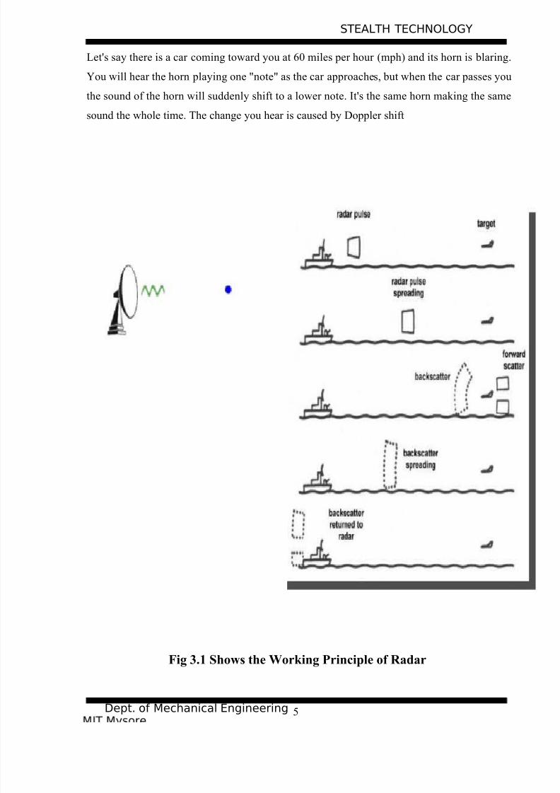
Radar is an object-detection system which uses electromagnetic waves  — specifically radiowaves — to determine the range, altitude, direction, or speed of both moving and fixed

objects such as aircraft, ships, spacecraft, guided missiles, motor vehicles, weather 

formations, and terrain. The radar dish, or antenna, transmits pulses of radio waves or 

microwaves which bounce off any object in their path. The object returns a tiny part of the

wave's energy to a dish or antenna which is usually located at the same site as the transmitter.

3.1 Principles of radar

It mainly works on the two principles:

1. ECHO and

2. DOPPLER SHIFT

Echo is used to detect time and distance of target

Doppler shift is used to detect the speed of target approaching

3.2 Echo and Doppler Shift

Echo is something you experience all the time. If you shout into a well or a canyon,

the echo comes back a moment later. The echo occurs because some of the sound waves in

your shout reflect off of a surface (either the water at the bottom of the well or the canyon

wall on the far side) and travel back to your ears. The length of time between the moment you

shout and the moment that you hear the echo is determined by the distance between you and

the surface that creates the echo.

Doppler shift is also common. You probably experience it daily (often without

realizing it). Doppler shift occurs when sound is generated by, or reflected off of, a moving

object. Doppler shift in the extreme creates sonic booms (see below). Here's how to

understand Doppler shift (you may also want to try this experiment in an empty parking lot).4

8/7/2019 STEALTH Tech Report

http://slidepdf.com/reader/full/stealth-tech-report 5/20

STEALTH TECHNOLOGY

Dept. of Mechanical Engineering

Let's say there is a car coming toward you at 60 miles per hour (mph) and its horn is blaring.

You will hear the horn playing one "note" as the car approaches, but when the car passes you

the sound of the horn will suddenly shift to a lower note. It's the same horn making the same

sound the whole time. The change you hear is caused by Doppler shift

Fig 3.1 Shows the Working Principle of Radar


5

8/7/2019 STEALTH Tech Report

http://slidepdf.com/reader/full/stealth-tech-report 6/20

STEALTH TECHNOLOGY

Dept. of Mechanical Engineering

STEALTH PRINCIPLES

4.1 Vehicle shape:

One of the important factors is the internal construction. Behind the skin of some

aircraft are structures known as re-entrant triangles. Radar waves penetrating the skin of the

aircraft get trapped in these structures, bouncing off the internal faces and losing energy.

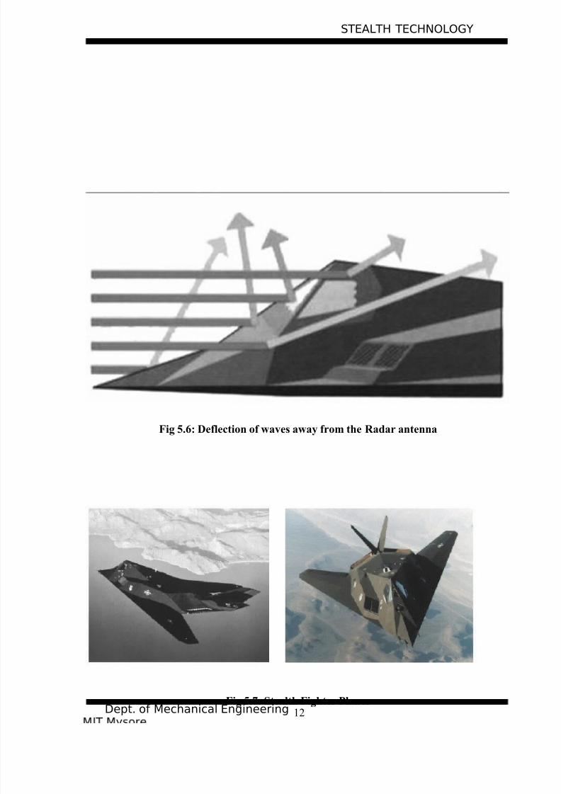
The most efficient way to reflect radar waves back to the transmitting radar is with

orthogonal metal plates, forming a corner reflector consisting of either a dihedral (two plates)

or a trihedral (three orthogonal plates). This configuration occurs in the tail of a conventionalaircraft, where the vertical and horizontal components of the tail are set at right angles.

Stealth aircrafts use a different arrangement, tilting the tail surfaces to reduce corner 

reflections formed between them.

Stealth design must also bury the engines within the wing or fuselage, or in some cases where

stealth is applied to an existing aircraft, install baffles in the air intakes, so that the turbine

 blades are not visible to radar. A stealthy shape must be devoid of complex bumps or 

 protrusions of any kind; meaning that – weapons, fuel tanks, and other stores must not be

carried externally. Any stealthy vehicle becomes un-stealthy when a door or hatch is opened.

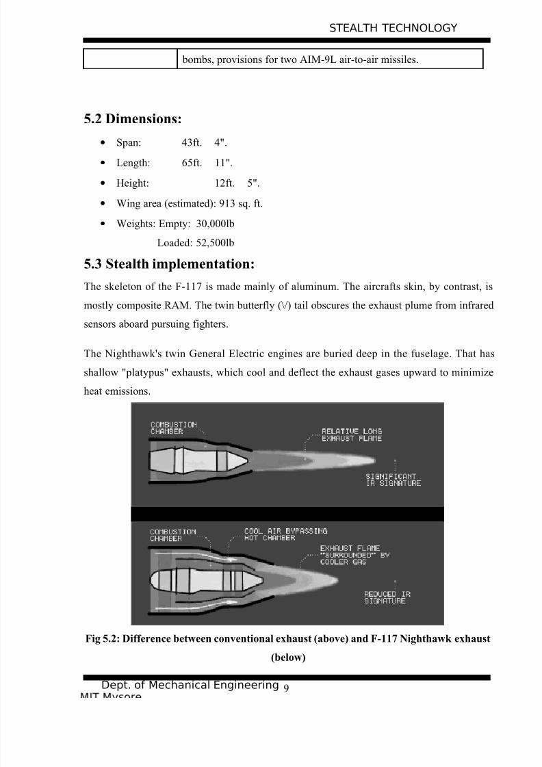
a. Propulsion subsystem shaping:

Fluidic nozzles for thrust vectoring with aircraft jet engines, and ships, will have lower RCS,

due to being less complex, mechanically simpler, with no moving parts or surfaces, and less

massive (up to 50% less). Fluidic nozzles divert thrust via fluid effects. Tests show that air 

forced into a jet engine exhaust stream can deflect thrust up to 15 degrees.

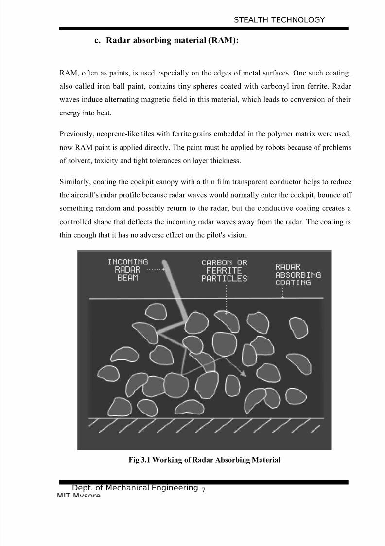
b. Non-metallic airframe:

Dielectric composites are relatively transparent to radar, whereas electrically conductive

materials such as metals and carbon fibers reflect electromagnetic energy incident on the

material's surface. Composites used may contain ferrites to optimize the dielectric and

magnetic properties of the material for its application.


6

8/7/2019 STEALTH Tech Report

http://slidepdf.com/reader/full/stealth-tech-report 7/20

STEALTH TECHNOLOGY

Dept. of Mechanical Engineering

c. Radar absorbing material (RAM):

RAM, often as paints, is used especially on the edges of metal surfaces. One such coating,

also called iron ball paint, contains tiny spheres coated with carbonyl iron ferrite. Radar 

waves induce alternating magnetic field in this material, which leads to conversion of their 

energy into heat.

Previously, neoprene-like tiles with ferrite grains embedded in the polymer matrix were used,

now RAM paint is applied directly. The paint must be applied by robots because of problems

of solvent, toxicity and tight tolerances on layer thickness.

Similarly, coating the cockpit canopy with a thin film transparent conductor helps to reduce

the aircraft's radar profile because radar waves would normally enter the cockpit, bounce off 

something random and possibly return to the radar, but the conductive coating creates a

controlled shape that deflects the incoming radar waves away from the radar. The coating is

thin enough that it has no adverse effect on the pilot's vision.

Fig 3.1 Working of Radar Absorbing Material


7

8/7/2019 STEALTH Tech Report

http://slidepdf.com/reader/full/stealth-tech-report 8/20

STEALTH TECHNOLOGY

Dept. of Mechanical Engineering

CASE STUDY: F-117 NIGHTHAWK 

In the Gulf War, it can be clearly seen on TV, the American air attack on Baghdad - they

were getting bombed, but they didn't know by what, they were shooting all over the sky

hoping for a hit, kind of pathetic last resort, it was F-117, Nighthawk. Forty F-117s were

deployed to the Gulf. Only 59 production F-117s were built, yet the total cost of the program

is over $6 billion!

Fig 5.1: F-117 Concept design

The Stealth can be refueled in flight but, rumors about the handling of the F-117, said it was

somewhat 'erratic', especially when refueling as a result, one of the first nicknames for the

 plane was "Wobblin' Goblin".

5.1 F-117 Nighthawk Specs:

Type: Single-seat low-observable strike fighter.

Manufacturer: Lockheed Martin

Maiden flight: 18 June 1981

Introduction: October 1983

Primary user: United States Air Force

Power plant:Two non-afterburning General Electric F404-GE-F1D2 engines,each delivering 10,800lb thrust.

Max Speed: Mach 1 (estimated)

Combat Radius: 750 mi. Un-refueled, with 5000lb weapon load.

Service ceiling: Not revealed.

Weapons: Up to 5,500lb, carried Internally and, principal weapons are BLU-109 low-level or GBU10/ GBU27 medium-level laser-guided8

8/7/2019 STEALTH Tech Report

http://slidepdf.com/reader/full/stealth-tech-report 9/20

STEALTH TECHNOLOGY

Dept. of Mechanical Engineering

 bombs, provisions for two AIM-9L air-to-air missiles.

5.2 Dimensions:

• Span: 43ft. 4".

• Length: 65ft. 11".

• Height: 12ft. 5".

• Wing area (estimated): 913 sq. ft.

• Weights: Empty: 30,000lb

Loaded: 52,500lb

5.3 Stealth implementation:The skeleton of the F-117 is made mainly of aluminum. The aircrafts skin, by contrast, is

mostly composite RAM. The twin butterfly (\/) tail obscures the exhaust plume from infrared

sensors aboard pursuing fighters.

The Nighthawk's twin General Electric engines are buried deep in the fuselage. That has

shallow "platypus" exhausts, which cool and deflect the exhaust gases upward to minimize

heat emissions.

Fig 5.2: Difference between conventional exhaust (above) and F-117 Nighthawk exhaust

(below)


9

8/7/2019 STEALTH Tech Report

http://slidepdf.com/reader/full/stealth-tech-report 10/20

STEALTH TECHNOLOGY

Dept. of Mechanical Engineering

The stealth fighter/bomber carries all its weapons internally, with no non-stealthy surfaces

left outside to be detected by radar. The edges of the F-177's cockpit canopy, like all surfaces,

have no right angles (right angles are strong radar reflectors).


10

8/7/2019 STEALTH Tech Report

http://slidepdf.com/reader/full/stealth-tech-report 11/20

STEALTH TECHNOLOGY

Dept. of Mechanical Engineering

Fig 5.3: Comparison between application regular and saw-toothed shapes in aircraft

parts

Fig 4.4 and Fig 4.5 clearly reveals the difference in the nose of a conventional aircraft and F-

117. The nose of F-117 is specially designed to deflect the radar waves away from the

antenna making the fighter invisible to the radar.

Fig 5.4: Reflection of waves back to the Radar antenna by the nose of a conventional

aircraft

Fig 5.5:

Deflection of 

waves away from

the Radar

antenna by the

nose of F-117 stealth fighter

11

8/7/2019 STEALTH Tech Report

http://slidepdf.com/reader/full/stealth-tech-report 12/20

STEALTH TECHNOLOGY

Dept. of Mechanical Engineering

Fig 5.6: Deflection of waves away from the Radar antenna

Fig 5.7: Stealth Fighter Planes


12

8/7/2019 STEALTH Tech Report

http://slidepdf.com/reader/full/stealth-tech-report 13/20

STEALTH TECHNOLOGY

Dept. of Mechanical Engineering

5.4 Nighthawk Engagement Profile:

The Stealth fighter/bomber detects its targets via the forward looking infrared turret, called

FLIR, embedded in its nose. This provides a good picture of the target from several miles

away, on even the darkest of nights.

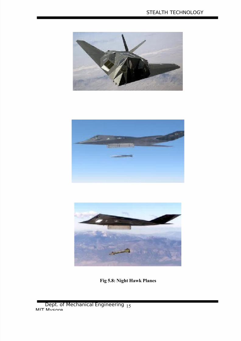
Bombing from medium altitude, the F-117's fire-control computer calculates the proper 

release point for the weapons to reach the general target vicinity. Weapons release will

generally be a range of one or two miles.

Closer to the target, control is switched to the downward looking infrared turret, or DLIR.

This is equipped with a laser designator.

As the weapon approaches the target, the laser designator is fired. Sensors in the nose of the

weapon now steer it toward to radar reflection, where it detonates with devastating accuracy.

5.5 Retirement:

Despite its successes in the Kosovo and Iraq Wars and its high mission-capable rate, the F-

117 was nevertheless designed with late 1970s technologies. Its stealth technology, while still

more advanced than that of any other aircraft except the B-2 Spirit, F-22 and F-35, is

maintenance heavy.

Furthermore, the facet-based stealth design has been surpassed by newer technology.Program Budget Decision 720 (PBD 720), dated 28 December 2005, proposed retiring the

entire fleet by October 2008 to allow for buying more F-22As. PBD 720 called for 10 aircraft

to be retired in financial year (FY) 2007 and the remaining 42 aircraft in FY 2008 and stated

there were other more capable Air Force assets that could provide low observable, precision

 penetrating weapons capability including the B-2, F-22 and JASSM.

By late 2006, the Air Force had closed the F-117 pilot school, and announced the retirement

of the F-117. The first six aircraft to be retired made the last flight on 12 March 2007 after a

ceremony at Holloman Air Force Base (AFB) to commemorate the aircraft's storied career.


13

8/7/2019 STEALTH Tech Report

http://slidepdf.com/reader/full/stealth-tech-report 14/20

8/7/2019 STEALTH Tech Report

http://slidepdf.com/reader/full/stealth-tech-report 15/20

STEALTH TECHNOLOGY

Dept. of Mechanical Engineering

Fig 5.8: Night Hawk Planes


15

8/7/2019 STEALTH Tech Report

http://slidepdf.com/reader/full/stealth-tech-report 16/20

STEALTH TECHNOLOGY

Dept. of Mechanical Engineering

ADVANTAGES

6.1 Increased combat efficiency:

A smaller number of stealth aircraft may replace a large fleet of conventional aircraft while

maintaining or increasing combat efficiency, possibly resulting in longer term savings in the

military budget.

d. Unopposed air strikes:

A stealth aircraft strike capability may put off potential opponents from taking action and

keep them in constant fear of unopposed air strikes, since they can never know if planes are

already under way, or what they might strike next. This may make an opponent more willing

to accept a diplomatic solution, although the moral reasoning behind this is disputed.

e. Possibility of avoiding war:

Stealth aircraft allow raids on important point targets to occur, while maintaining a cover.

Since the approach and departure routes would likely remain unknown, a stealth operator 

could simply refuse to comment and hope to avoid war.

f. Weakening of opposite party:

The production and fielding of stealth combat aircraft design may force an opponent to

 pursue the same aim, possibly resulting in significant weakening of the economically inferior 

 party. The 1980s American Strategic Defense Initiative program served a similar purpose

against the USSR.


16

8/7/2019 STEALTH Tech Report

http://slidepdf.com/reader/full/stealth-tech-report 17/20

STEALTH TECHNOLOGY

Dept. of Mechanical Engineering

LIMITATIONS

7.1 Instability of design:

Stealth aircraft are designed with a focus on minimal RCS rather than aerodynamic

  performance. Highly stealth aircraft are aerodynamically unstable in all three axes and

require constant flight corrections from the fly-by-wire system to maintain controlled flight.

g. Reduced payload:

Fully stealth aircraft carry all armament internally, which limits the payload. By way of 

comparison, the F-117 carries only two laser or GPS guided bombs, while a non-stealth

attack aircraft can carry several times more.

h. Cost of operations:

Stealth aircraft are typically more expensive to develop and manufacture. An example is the

B-2 Spirit that is many times more expensive to manufacture and support than conventional

 bomber aircraft. The B-2 program cost the U.S. Air Force almost $45,000 million.


17

8/7/2019 STEALTH Tech Report

http://slidepdf.com/reader/full/stealth-tech-report 18/20

STEALTH TECHNOLOGY

Dept. of Mechanical Engineering

MEASURING STEALTH

The size of a target’s image on radar is measured by the radar cross section (RCS), often

represented by the symbol σ and expressed in sq. meters. This does not equal geometric

area. A perfectly conducting sphere of projected cross sectional area 1m2 (i.e., a diameter of 

1.13m) will have an RCS of 1m2. Note that for radar wavelengths much less than the

diameter of the sphere RCS is independent of frequency. Conversely, a flat plate of area 1m 2

will have an RCS of about 14000m2 at 10 GHz if the radar is perpendicular to the flat

surface. If you rotate it, the amount of energy reflected directly back to the transmitter is

reduced as some is reflected to the side, so the RCS is reduced. Modern stealth aircraft are

said to have an RCS comparable with small birds or large insects, though this varies widely

depending on aircraft and radar.

If the RCS was directly related to the target’s cross sectional area, the only way to reduce it

would be to make the physical profile smaller. Rather, by reflecting much of the radiation

away or absorbing it all together, the target achieves a smaller RCS.


18

8/7/2019 STEALTH Tech Report

http://slidepdf.com/reader/full/stealth-tech-report 19/20

STEALTH TECHNOLOGY

Dept. of Mechanical Engineering

9. CONCLUSION

To date, stealth aircraft have been used in several low and moderate intensity conflicts,

including Operation Desert Storm, Operation Allied Force and the 2003 invasion of Iraq. In

each case they were employed to strike high-value targets which were either out of range of 

conventional aircraft in the theater or which were too heavily defended for conventional

aircraft to strike without a high risk of loss.

In addition, because the stealth aircraft do not have to evade surface-to-air missiles and anti-

aircraft artillery over the target they can aim more carefully and thus are more likely to hit

the target and not cause as much collateral damage.

The stealth aircrafts as well as other war machines like stealth ships, submarines are the key

for dominance in the battlefield of the future.


19

8/7/2019 STEALTH Tech Report

http://slidepdf.com/reader/full/stealth-tech-report 20/20

STEALTH TECHNOLOGY

Dept. of Mechanical Engineering

10. REFERENCE:

• Future Flight: The Next Generation of Aircraft Technology, William D. Siuru , Jhon

D. Busick, Published 1933 McGrew-Hill Professional, 194 pages, ISBN 0830643761

•  Have Blue and the F-117A: Evolution of “Stealth Fighter”, By David C. Aronstein,

Albert C Piccirillo, Published 1997 American Institute of Aeronautics and Astronautics,

305 pages, ISBN 1563472457

• Stealth technology: The Art of Back Magic, By J. Jones, Matt Thunder 

• http://www.geocities.com/Area51/Shadowlands/6583/projects.html

• http://en.wikipedia.org/w/index.php?title=Stealth_aitcraft

• http://en.wikipedia.org/wiki/F-117_Nighthawk 


20


Recommended