In presenting this thesis in partial fulfilment of the requirements for an advanced
degree at the University of British Columbia, I agree that the Library shall make it
freely available for reference and study. I further agree that permission for extensive
copying of this thesis for scholarly purposes may be granted by the head of my
department or by his or her representatives. It is understood that copying or
publication of this thesis for financial gain shall not be allowed without my written
permission.
Department of jA&TALS AMD rAATagvAlS £r>&lMfc£fllMG
The University of British Columbia Vancouver, Canada
Date O C T O B E R IS,
DE-6 (2/88)
ABSTRACT
The manufacturing of steel bar products in mini-mills involves the continuous
casting of billet sections, cooling of the billets, reheating to rolling temperatures and final
shaping and size reduction in rolling mills. The operation of such furnaces can be a
challenge due to the dynamic nature of both the reheating and rolling processes. The
operation of a furnace was analyzed with the use of a S C A D A data collection system,
steady state and transient mathematical models. The new knowledge gathered in this way
was complimented by existing knowledge from experienced mi l l personnel to form the
basis for an expert system designed to offer timely advice to furnace operators. The
result was the development of an industrial expert system leading to an increase in
furnace mi l l productivity.
n
TABLE OF CONTENTS
A B S T R A C T ii
T A B L E O F C O N T E N T S iii
L I S T O F T A B L E S v
L I S T O F F I G U R E S vi
G L O S S A R Y viii
A C K N O W L E D G M E N T S x
C H A P T E R 1. I N T R O D U C T I O N 1
C H A P T E R 2. B A C K G R O U N D A N D P R E V I O U S W O R K 3
C H A P T E R 2.1. T H E S T E E L R E H E A T I N G F U R N A C E : 3
C H A P T E R 2.2. P R O B L E M S A S S O C I A T E D WITH R E H E A T I N G F U R N A C E O P E R A T I O N : 8
C H A P T E R 3. E X P E R T A N D S C A D A S Y S T E M S 19
C H A P T E R 3.1. E X P E R T SYSTEMS: 19
C H A P T E R 3.2. E X A M P L E S OF E X P E R T SYSTEMS: 22
C H A P T E R 3.3. P R O P O S E D I M P L E M E N T A T I O N OF A N E X P E R T S Y S T E M T O T H E R E H E A T I N G F U R N A C E : 2 8
C H A P T E R 3.4. O B T A I N I N G A N D PROCESSING F U R N A C E D A T A - T H E SUPERVISORY C O N T R O L A N D D A T A
AQUISITION ( S C A D A ) S Y S T E M : 33
C H A P T E R 4. S C O P E A N D O B J E C T I V E S 38
C H A P T E R 4.1. S C O P E OF T H E PROJECT: 38
C H A P T E R 4.2. OBJECTIVES OF T H E PROJECT: 39
C H A P T E R 5. - M E T H O D O L O G Y 41
C H A P T E R 5.1. A P P R O A C H T O T H E R E H E A T I N G P R O B L E M : 41
C H A P T E R 5.2. I M P L E M E N T A T I O N O F T H E E X P E R T S Y S T E M : 45
C H A P T E R 5.3. T H E I N S T A L L E D E X P E R T S Y S T E M : 47
C H A P T E R 5.4. A N A L Y S I S OF T H E F U R N A C E OPERATION D A T A : 63
C H A P T E R 5.5. A N A L Y S I S OF T H E O P T I C A L P Y R O M E T E R D A T A : 66
C H A P T E R 5.6. A N A L Y S I S OF T H E B I L L E T GROUPINGS: 67
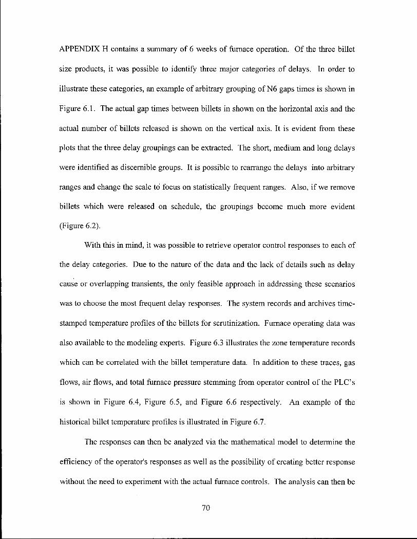
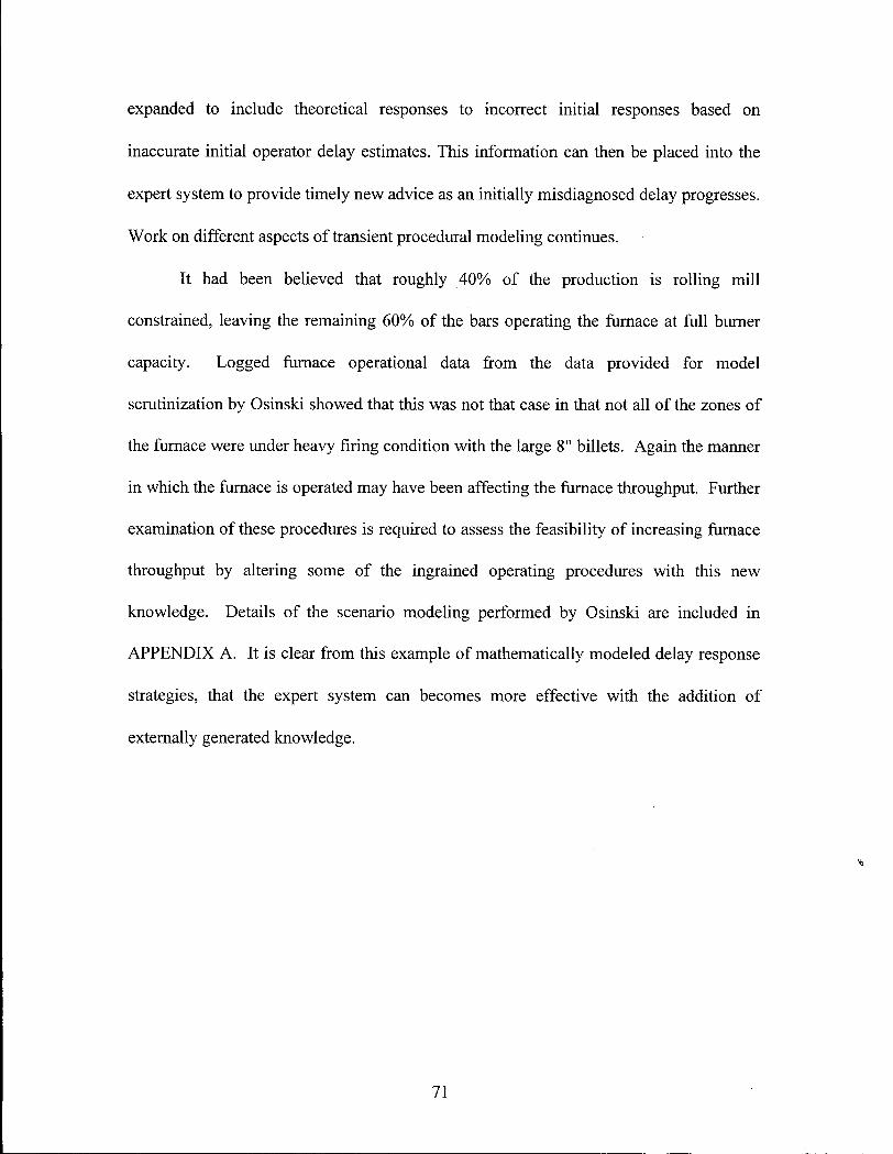
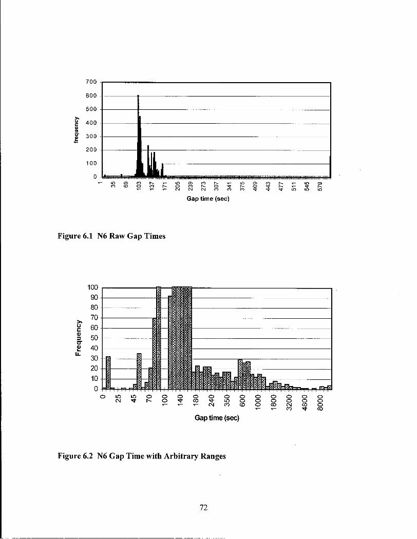
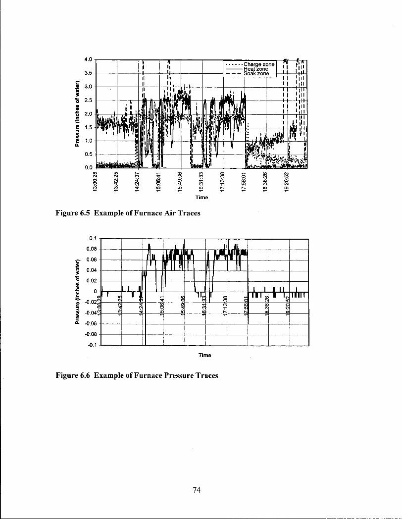
C H A P T E R 6. R E S U L T S A N D D I S C U S S I O N : 69
C H A P T E R 6.1. T H E E X P E R T S Y S T E M : 69
C H A P T E R 6.2. T H E I N T E R F A C E & O P E R A T O R RESPONSE: 76
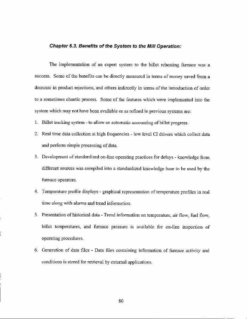
C H A P T E R 6.3. BENEFITS OF T H E S Y S T E M T O T H E M I L L OPERATION: 80
C H A P T E R 7. C O N C L U S I O N S 81
B I B L I O G R A P H Y 82
A P P E N D I X A M A T H E M A T I C A L M O D E L I N G R E S U L T S 85
A P P E N D I X B H A R D W A R E 92
i i i
APPENDIX C SOFTWARE 93
APPENDIX D PLANT TRIALS 94
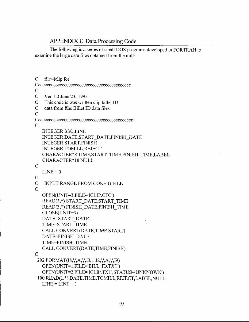
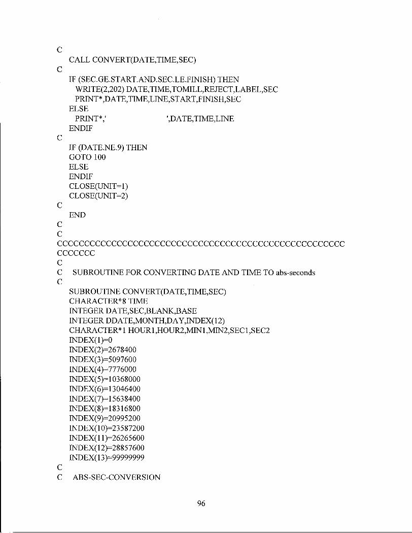
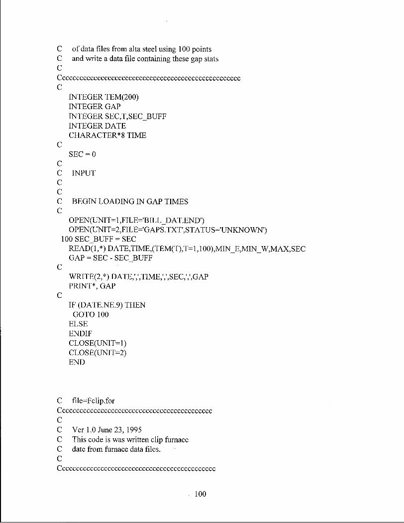
APPENDIX E DATA PROCESSING CODE 95
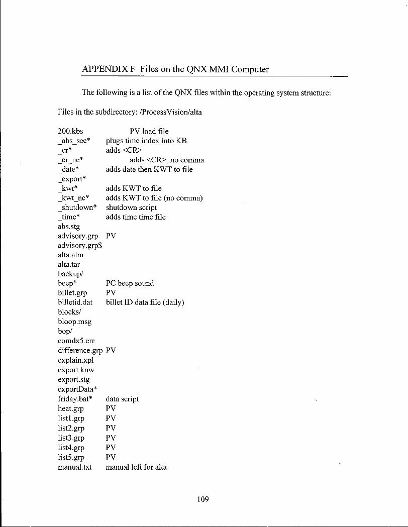
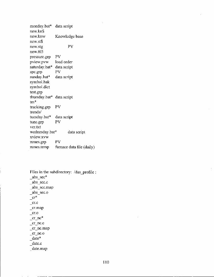
APPENDIX F FILES ON THE QNX MMI COMPUTER 109
APPENDIX G COMDALE/C KNOWLEDGE BASE CODE 115
APPENDIX H RAW AND PROCESSED DATA FROM 6 OPERATING WEEKS 152
IV
LIST OF TABLES
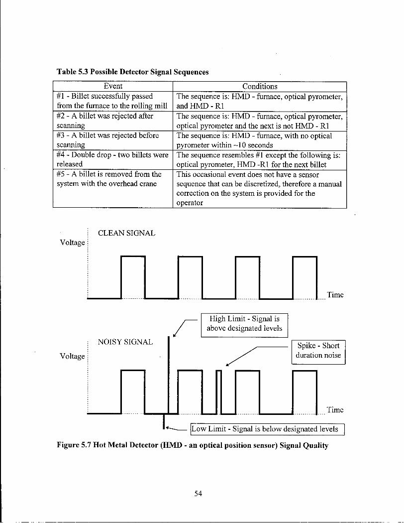
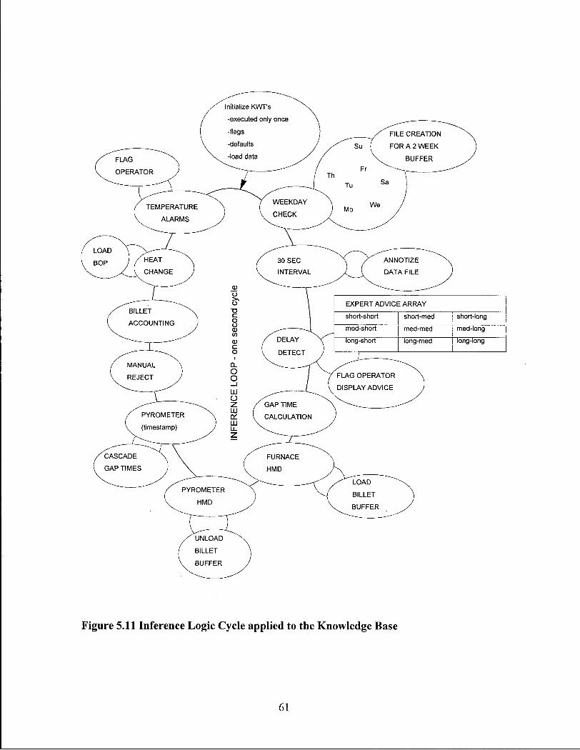
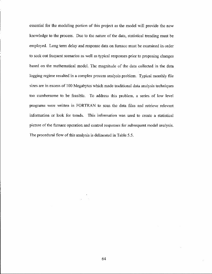
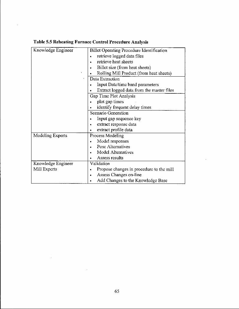
Table 3.1 Description of Data/Knowledge Stream 32 Table 5.1 Possible Outcomes of Delay Time Estimation and Error Consequences 44 Table 5.2 Possible Outcomes of Delay Time Estimation and Control Responses 44 Table 5.3 Possible Detector Signal Sequences 54 Table 5.4 Child Processes Within the Inference Engine 62 Table 5.5 Reheating Furnace Control Procedure Analysis 65
Appendix Tables
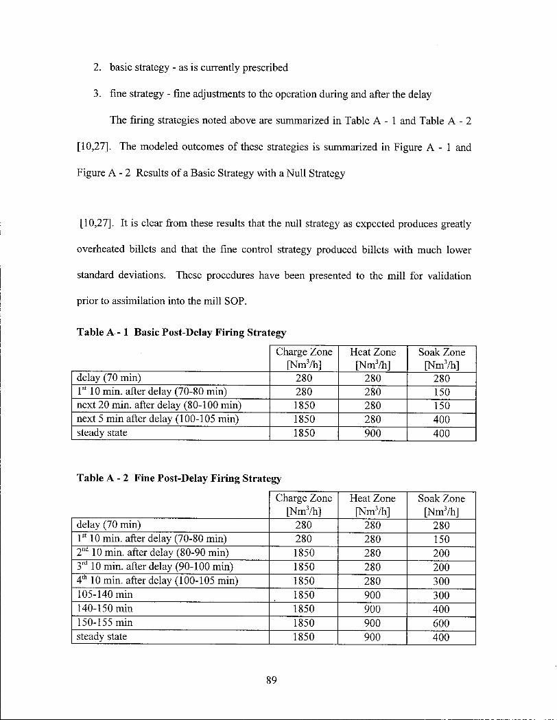
Table A - 1 Basic Post-Delay Firing Strategy 89 Table A - 2 Fine Post-Delay Firing Strategy 89
v
LIST OF FIGURES Figure 2.1 Conversion from Scrap to Billet Steel 4 Figure 2.2 Schematic of the Post-heating Rolling Process 4 Figure 2.3 Side View of the Furnace 5 Figure 2.4 Existing Control Flow Diagram 6 Figure 2.5 End View Schematic of the Billet Support Beams 10 Figure 2.6 Top View of Billets Resting on Support Beams 11 Figure 2.7 Typical Axial Temperature Profile 11 Figure 2.8 Effect of Carbon Content on Steel Melting Temperature 15 Figure 2.9 Schematic of the Migration of Carbon from the Steel into the Combustion Atmosphere 16 Figure 2.10 Limiting conditions of time and temperature for various degrees of decarburization in
3" slab based upon isothermal data. 17 Figure 3.1. Pyrolysis Chamber for Alumina Fibres 24 Figure 3.2 Schematic of the Data and Knowledge Streams 31 Figure 3.3 QNX multitasking operating system 33 Figure 3.4 Knowledge Units Available to Comdale/C 36 Figure 3.5 Independent Application Modules 37 Figure 5.1 Interim Logging System 46 Figure 5.2 Block Diagram of the Current System 46 Figure 5.3 Block Diagram of the Proposed System 46 Figure 5.4 MMI Billet Profile Screen 49 Figure 5.5 SOP Product Selection Screen 53 Figure 5.6 Schematic of the Mill Sensor Layout 53 Figure 5.7 Hot Metal Detector (HMD - an optical position sensor) Signal Quality 54 Figure 5.8 Historical Furnace Operation Screen - Gas Flows 55 Figure 5.9 Historical Furnace Operation Screen - Temperatures 56 Figure 5.10 Advisory Screen 57 Figure 5.11 Inference Logic Cycle applied to the Knowledge Base 61 Figure 6.1 N6 Raw Gap Times 72 Figure 6.2 N6 Gap Time with Arbitrary Ranges 72 Figure 6.3 Example of Furnace Zone Temperature Traces 73 Figure 6.4 Example of Furnace Natural Gas Traces 73 Figure 6.5 Example of Furnace Air Traces 74 Figure 6.6 Example of Furnace Pressure Traces 74 Figure 6.7 Plot of Billet Temperature Profiles Over Time 75
Appendix Figures
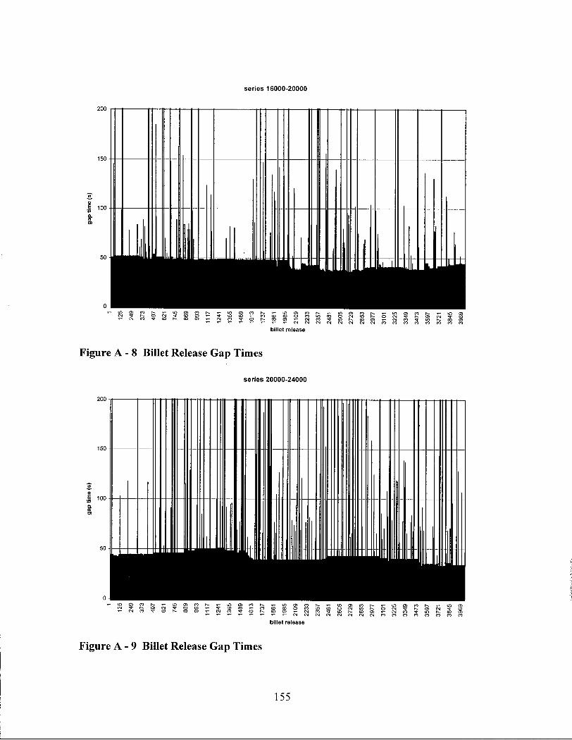
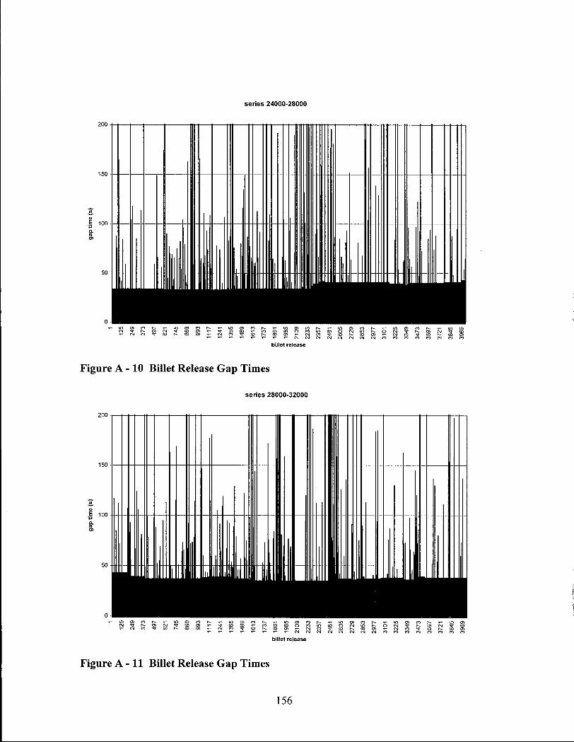
Figure A -1 Plant Trial Results as Compared with Modeling Results 85 Figure A - 2 Results of a Basic Strategy with a Null Strategy 90 Figure A - 3 Results of a Fine Strategy with a Null Strategy 90 Figure A - 4 Billet Release Gap Times 153 Figure A - 5 Billet Release Gap times 153 Figure A - 6 Billet Release Gap Times 154 Figure A - 7 Billet Release Gap Times 154 Figure A-8 Billet Release Gap Times 155 Figure A-9 Billet Release Gap Times 155 Figure A -10 Billet Release Gap Times 156 Figure A -11 Billet Release Gap Times 156 Figure A -12 Billet Release Profile - 40 second target 157 Figure A -13 Modified Billet Release Profile - 40 second target 157
vi
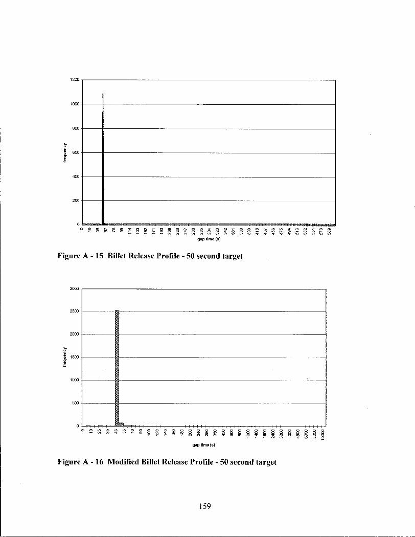
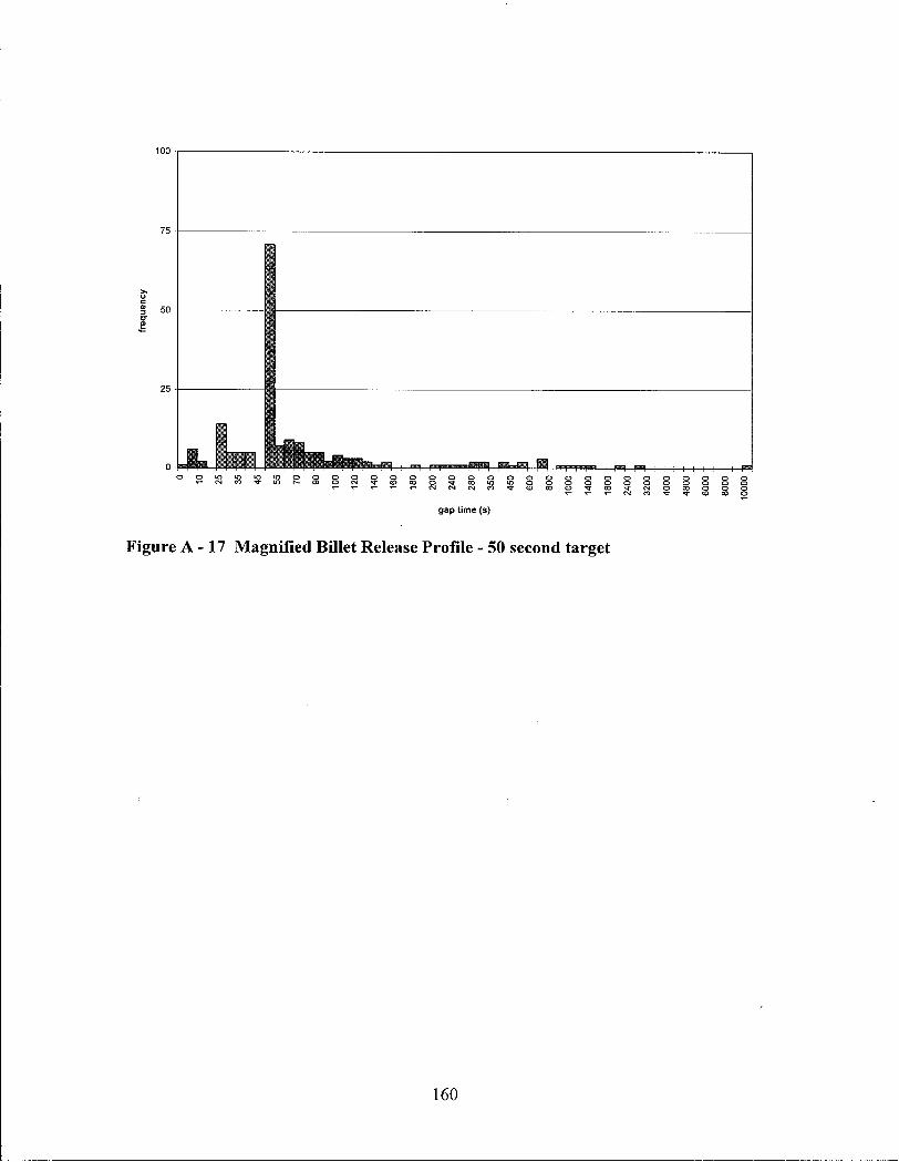
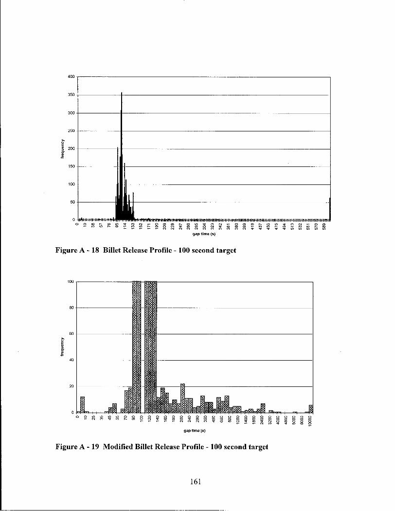
Figure A -14 Magnified Billet Release Profile - 40 second target 158 Figure A - 15 Billet Release Profile - 50 second target 159 Figure A - 16 Modified Billet Release Profile - 50 second target 159 Figure A - 17 Magnified Billet Release Profile - 50 second target 160 Figure A-18 Billet Release Profile -100 second target 161 Figure A - 19 Modified Billet Release Profile -100 second target 161 Figure A - 20 Magnified Billet Release Profile - 100 second target 162
v i i
\
GLOSSARY
A l - "Artificial Intelligence is a collection of computer-based techniques, based on the manipulation of symbols rather than numbers, which enable computer to produce behavior which resembles that previously only seen in humans." [1,2]
Bar- Describes a section of billets which has been deformed and is currently being rolled in the rolling m i l l
B E T A - the second phase of software development in which developers w i l l make a limited release of the code in an unfinished form in order to obtain user feedback from final users.
Bil let - A raw steel section prior to rolling typically less than 16 ft long, square section of 4 3/4", 6" or 8" for our mi l l (corresponds to N 2 , N 3 , and N6)
Cobble - A bar misfed or tangled in mid rolling causing a stoppage in the rolling operation
Comdale/C - Real-Time expert system software like Comdale/X but is capable of managing real-time inputs from the processes and making Expert control contributions
Comdale/X - Expert system software including knowledge base generator, inference engine and man/machine interface- written by Comdale Technologies.
Degree of Bel ief - The percentage in which one believes a proposition is correct Degree of Certainty - The percentage certainty that a piece of information is correct Heat - A single batch of heated steel conforming to a set of metallurgical standards which
is destined for casting and rolling. Heuristics - A set of information, knowledge and procedures which is used in problem
solving H M D - Hot Metal Detector - "electric eye" with a narrow range of vision which is
sensitive to infrared radiation, i.e. the radiant energy from the hot billet as it passes a point in front of the detector.
Inference Engine- The C P U of an expert system which performs knowledge based reasoning.
ISO9002 - The international standard which manufacturing companies must comply to be able to carry the ISO9002 qualify insignia.
Key Word Triplet - The sequence of three words link into a symbolic representation of a piece of knowledge, e.g. "object.attribute.value" each with a degree of certainly attached
M M I - M a n Machine Interface - The interface between the process and the operator, can but does not necessary include control
Pace - The distance that the walking beam moves the billets on each walk. This is also equal to the billets spacing or some whole fraction of the billet spacing.
Pace rate - the rate at which the billets are walked through the furnace (i.e. steps/min)
v i i i
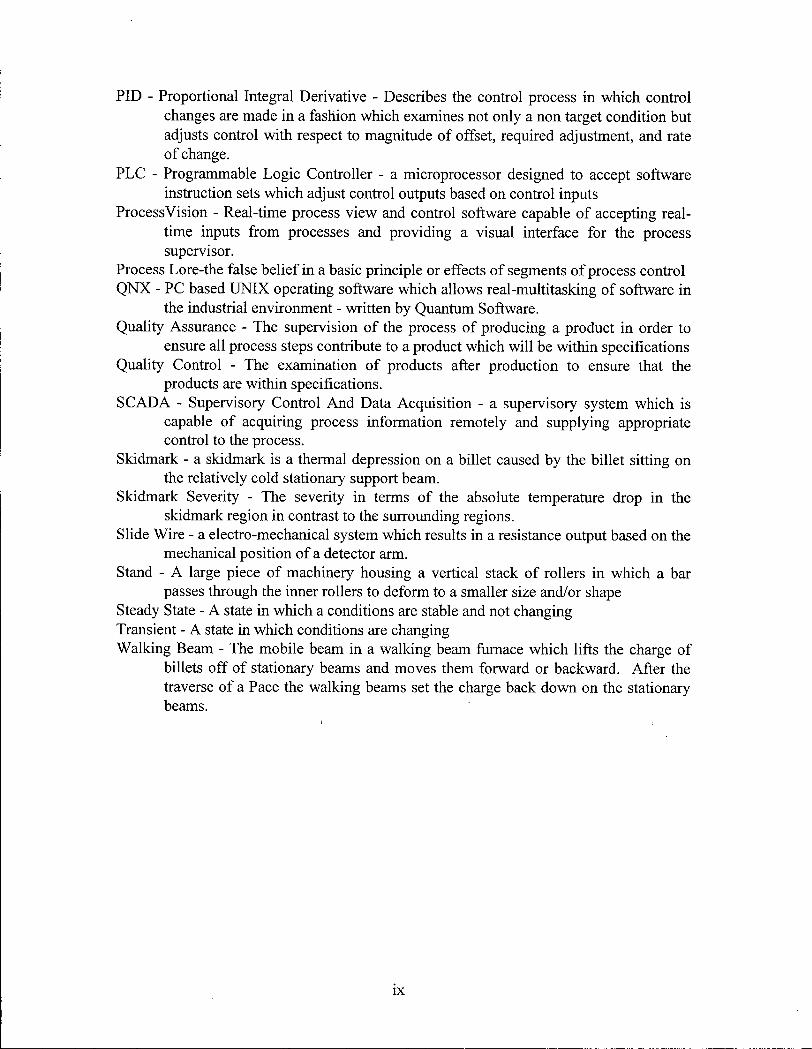
PID - Proportional Integral Derivative - Describes the control process in which control changes are made in a fashion which examines not only a non target condition but adjusts control with respect to magnitude of offset, required adjustment, and rate o f change.
P L C - Programmable Logic Controller - a microprocessor designed to accept software instruction sets which adjust control outputs based on control inputs
ProcessVision - Real-time process view and control software capable of accepting realtime inputs from processes and providing a visual interface for the process supervisor.
Process Lore-the false belief in a basic principle or effects of segments of process control Q N X - P C based U N I X operating software which allows real-multitasking of software in
the industrial environment - written by Quantum Software. Quality Assurance - The supervision of the process of producing a product in order to
ensure all process steps contribute to a product which wi l l be within specifications Quality Control - The examination of products after production to ensure that the
products are within specifications. S C A D A - Supervisory Control A n d Data Acquisition - a supervisory system which is
capable of acquiring process information remotely and supplying appropriate control to the process.
Skidmark - a skidmark is a thermal depression on a billet caused by the billet sitting on the relatively cold stationary support beam.
Skidmark Severity - The severity in terms of the absolute temperature drop in the skidmark region in contrast to the surrounding regions.
Slide Wire - a electro-mechanical system which results in a resistance output based on the mechanical position of a detector arm.
Stand - A large piece of machinery housing a vertical stack of rollers in which a bar passes through the inner rollers to deform to a smaller size and/or shape
Steady State - A state in which a conditions are stable and not changing Transient - A state in which conditions are changing Walking Beam - The mobile beam in a walking beam furnace which lifts the charge of
billets off of stationary beams and moves them forward or backward. After the traverse of a Pace the walking beams set the charge back down on the stationary beams.
ACKNOWLEDGMENTS
I would like to express my deepest appreciation to Dr. Peter Barr and Dr. John
Meech for their support and guidance towards the completion of this project. In addition
I would like to thank Dr. Keith Brimacombe, Dr. Indira Samarasekera, and the Centre for
Metallurgical Process Engineering and N S E R C for both financial and moral support in
this endeavor. I owe a debt of gratitude to Vladimir Rakocevic for his invaluable
assistance in creating the hardware drivers required by my system. I would like to
acknowledge the assistance of the personnel at Al ta Steel, Bob Pugh, Doug Ostafichuk,
Dennis Gutknecht, Mark Burrough, E d Duchesne, and the furnace operators for their
support and patience during the system installation and operation.
Special thanks go out to my friends and colleagues for their inspirational
conversations and to my family for supporting all o f my decisions.
x
Chapter 1. In t roduc t ion
In a typical minimil l steelmaking plant, the reheating furnace is situated between
the caster which produces the billets, and the rolling mi l l which shapes the billets, into
finished products. The operation of a steel billet reheating furnace located in Alberta,
Canada w i l l be utilized for our analysis. The production of material such as construction
rebar or rail sections involves the conversion of raw billets into hot rolled products.
Billets must be heated in furnaces in order to bring average temperatures to a point at
which the billets can be rolled with reasonably low forces as well as result in the proper
microstructure at the end of the process. In the ideal world of furnaces operated within
steel rolling mills, all processes run at steady state and no problems occur to disturb this
perfect equilibrium. In this perfect world, steel billets are charged cold into the furnace
and are removed hot at regular intervals, all of which are homogeneously heated prior to
hot rolling in the downstream mi l l rolls. The furnace, of course, would be operated at
optimal steady-state conditions at all times and would never require adjustment. The
rolling mi l l would be able to accept these billets in a timely fashion and would shape all
of the bars successfully into rolled products. Unfortunately, this ideal world does not
exist.
In the real world, furnaces routinely experience transient conditions. For
example, scheduled delays due to regular downstream roll changes or unscheduled delays
due to unexpected cobbles are a few of the conditions that may be encountered during the
initial charging of billets. Furnaces have large thermal inertia - things change slowly and
1
errors take time to recover. Control of the furnace temperatures is critical i f the desired
result is to produce a homogeneously heated product billet at the proper time and proper
temperature. Intelligent control of this process is the responsibility of experienced
furnace operators whom base their decisions on a myriad of different factors.
Consistency of such operator-based control can be poor at the best of times therefore a
systematic, computerized, approach seems to be the solution.
Artificial Intelligence is defined as "a collection of computer-based techniques,
based on the manipulation of symbols rather than numbers, which enable computers to
produce behavior which resembles that previously only seen in humans" [1,2]. Expert
Systems involve the application of Artificial Intelligence concepts to real world
problems. Expert Systems operate very differently from conventional computer
programs in that the problem solving techniques, or "heuristics", mimic human problem
solving. Expert systems would therefore have a distinct advantage over conventional
control schemes in experience laden applications such as steel reheating furnaces. The
ultimate goal of this exercise is to improve product consistency and to lower mi l l
operating costs.
2
Chapter 2. Background and Previous Work
Chapter 2.1. The Steel Reheating Furnace:
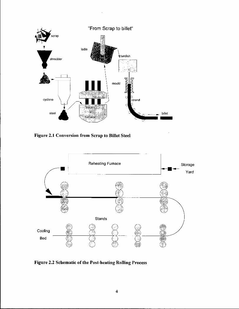
The facility chosen for the implementation of this expert system was a mini-mil l
located in Alberta, Canada. The mi l l buys scrap steel on the open market, melts the raw
material in an electric arc furnace and makes metallurgical adjustments to composition
prior to a continuous casting process for the production of steel billets. The billets cast
are square sections with dimension 4 3 / 4 " , 6", or 8" which are cut to lengths up to 16 feet
long. The process from scrap to billet is illustrated in Figure 2.1. These billets are taken
to a storage yard where they are cooled prior to scheduled charging into a natural gas
fired steel reheating furnace. These billets are heated in the furnace to obtain a
homogeneity of temperature prior to hot forming. The hot billets from the furnace are
then shaped in a rolling mi l l to produce bar products such as grinding stock, railway
tracks, rebar, and structural stock. The schematic in Figure 2.2 illustrates the billet
processing from raw billets to final rolled product.
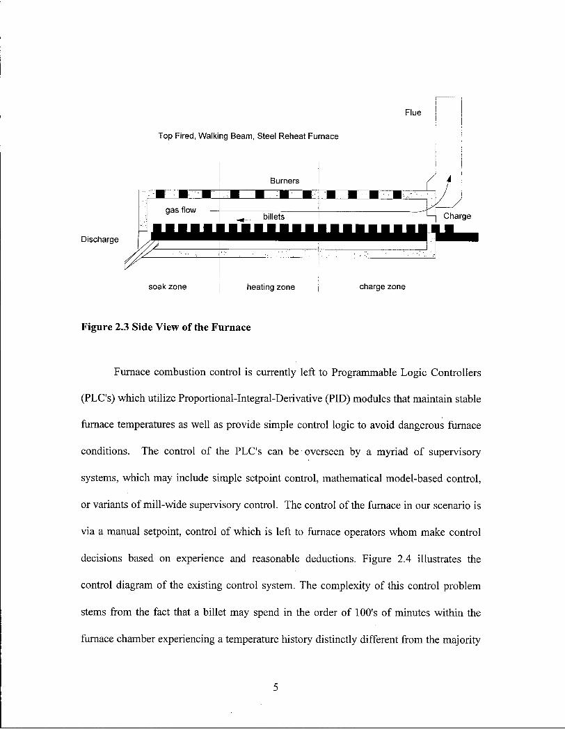
The natural gas fired furnace utilizes a combination of stationary and walking
beams which carry the billets into and out of the heating zones. The furnace is 16 feet,
wide and 57 feet long and handles the billets in an orientation perpendicular to the axis of
movement. The furnace is separated into three distinct control zones in which individual
P L C s (programmable logic controllers) control the zone temperatures in accordance to
the setpoints chosen by the furnace operator on shift. Figure 2.3 illustrates the side cut
away view of the reheating furnace
3
"From Scrap to billet"
Figure 2.1 Conversion from Scrap to Billet Steel
Reheating Furnace Storage
Yard
Stands
Cooling
Bed
Figure 2.2 Schematic of the Post-heating Rolling Process
4
Flue
Top Fired, Walking Beam, Steel Reheat Furnace
Discharge
gas flow —
soak zone heating zone charge zone
Figure 2.3 Side View of the Furnace
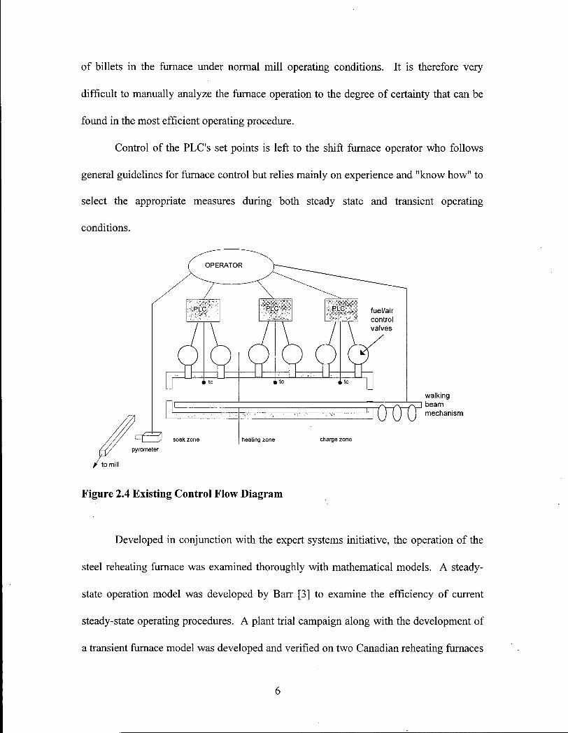
Furnace combustion control is currently left to Programmable Logic Controllers
(PLC's) which utilize Proportional-Integral-Derivative (PID) modules that maintain stable
conditions. The control of the P L C ' s can be overseen by a myriad of supervisory
systems, which may include simple setpoint control, mathematical model-based control,
or variants of mill-wide supervisory control. The control of the furnace in our scenario is
via a manual setpoint, control of which is left to furnace operators whom make control
decisions based on experience and reasonable deductions. Figure 2.4 illustrates the
control diagram of the existing control system. The complexity of this control problem
stems from the fact that a billet may spend in the order of 100's of minutes within the
furnace chamber experiencing a temperature history distinctly different from the majority
furnace temperatures as well as provide simple control logic to avoid dangerous furnace
5
of billets in the furnace under normal mi l l operating conditions. It is therefore very
difficult to manually analyze the furnace operation to the degree of certainty that can be
found in the most efficient operating procedure.
Control of the P L C ' s set points is left to the shift furnace operator who follows
general guidelines for furnace control but relies mainly on experience and "know how" to
select the appropriate measures during both steady state and transient operating
conditions.
walking beam mechanism
Figure 2.4 Existing Control Flow Diagram
Developed in conjunction with the expert systems initiative, the operation of the
steel reheating furnace was examined thoroughly with mathematical models. A steady-
state operation model was developed by Barr [3] to examine the efficiency of current
steady-state operating procedures. A plant trial campaign along with the development of
a transient furnace model was developed and verified on two Canadian reheating furnaces
6
by Scholey [4]. These mathematical models along with the scenario development by
Osinski [3] would become integral to the development of this project.
7
Chapter 2.2. Problems Associated with Reheating Furnace Operation:
In producing bar products, the ideal situation would be to transfer hot billets
directly from the continuous caster to the rolling mi l l in order to utilize the sensible heat
already within the steel [5]. Unfortunately this is not feasible due to the inability to detect
and remove surface defects from the raw billets prior to rolling as well as the enormous
problems involved with scheduling the caster and rolling mi l l to operate in perfect
harmony. A s a result of these problems, steel reheating furnaces are necessary in order to
heat the cold continuously cast steel billets to temperatures at which reasonable forces
can be used in the roll stands since hot rolling stresses are inverse exponential functions
of temperature [6]. The rolling m i l l requires production of homogeneously heated billets
within temperature specifications at intervals dictated by the rate at which the rolling mi l l
can reduce the sections to final dimensions.
The billets must have sufficient time within the furnace in order to absorb enough
heat to attain the target temperature. It is also necessary for the billets to homogenize, or
"soak", for a minimum amount of time to ensure a fair degree of temperature uniformity.
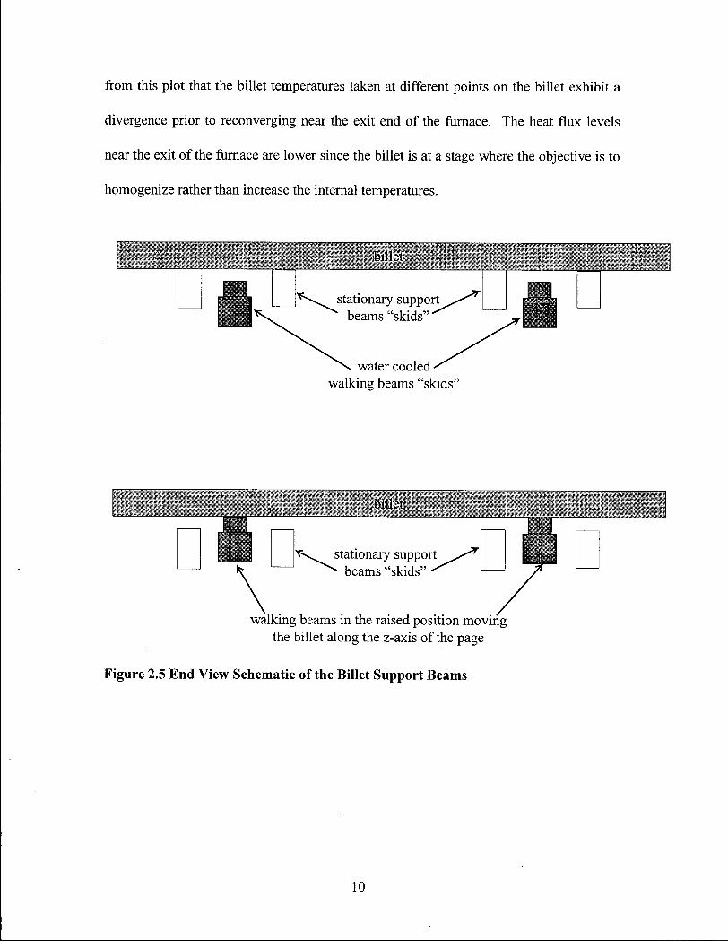
One problem in establishing homogeneity of temperature is a localized depression of
temperature, known as a skidmark, caused by the portion of the billet sitting on the
relatively-cold stationary support beam or skid. Figure 2.5 and Figure 2.6 show the
geometry of the billets with respect to the water cooled support skids. These billet
heating factors result in long minimum furnace residence times. Since the rolling mi l l
8
demands a hot billet every few minutes, the time to temperature plot for each individual
billet presents a furnace operation problem which involves careful scheduling, furnace
temperature control, and considerable experience in order to maximize production and
minimize losses.
Whether operating under steady state or transient conditions, skidmarks are
unavoidable. While a billet is in a reheating furnace, it must rest on stationary beams
designed to aid in the transfer of heat into the billet by exposing the bottom side of the
billet to the hot radiative faces of the furnace as well as the convective heating of the hot
combustion gases. Unfortunately, these support beams are water cooled and do not allow
the same level of heat flux into the contact area. The result is a temperature depression,
or skidmark. Skidmarks can be minimized by design features such as "hot faced" beams
or perhaps staggered support beams which allow the affected area to change as the billet
progresses along the axis of the furnace. However, skidmarks are unavoidable and affect
the ability of the mi l l to roll the billet after discharge, even possibly to the extent of
affecting the local post-rolled tolerances in the skidmark region [5]. The operation of the
furnace in the soak (final) zone does not change the skidmark severity but also does not
allow the feature to worsen (a long soak in a section without cooled supports would
reduce skidmarks but the space and residence time required makes this impractical).
While in the soak zone, skidmark severity is stabilized while the top to bottom
temperatures are allowed to converge. This top to bottom difference is particularly
evident in top fired furnaces. A typical axial furnace temperature profile is shown in
Figure 2.7 [4]. The diagram shows data taken from plant trials which were obtained by
tracking the progress of a billet through the furnace with thermocouples. It is evident
9
from this plot that the billet temperatures taken at different points on the billet exhibit a
divergence prior to reconverging near the exit end of the furnace. The heat flux levels
near the exit of the furnace are lower since the billet is at a stage where the objective is to
homogenize rather than increase the internal temperatures.
hi lie;
walking beams in the raised position moving the billet along the z-axis of the page
Figure 2.5 End View Schematic of the Billet Support Beams
10
Top view
Billet walking direction
Figure 2.6 Top View of Billets Resting on Support Beams
11
In the normal steady state operation of the furnace, issues such as zone
temperatures, charge rate, furnace pace rates, etc. are consistent and do not require much
attention. Once good operating conditions are found for steady state operation, they
usually do not change substantially and become the basis of the furnace "static"
knowledge. Static knowledge is easily quantifiable and can be updated as new factors or
revelations concerning the steady state operation are uncovered. It is in the transient
states such as startup, shutdown, product changes, and unscheduled delays that the
control of the furnace becomes more challenging.
In transient situations such as at startup, the billets are charged and heated in a
variety of ways. In order to maximize the efficiency of the furnace in transferring heat to
the billets in an expedient fashion, the space between billets may be doubled (a practice
known as "double spacing") to increase the view factors thereby increasing heat flux into
the exposed faces (the view factor is the fraction of the furnace which the billet face is
exposed). Unfortunately, this is not the most optimal fuel efficient method due to high
heating rates and low throughputs. In addition, temperature homogeneity may be
sacrificed from such rapid heating rates. A t some point, the furnace charge must be
changed to single spaced causing a transient control situation and subsequently a
nontrivial difference in temperature history for each billet traveling through the
combustion chamber.
Furnace shutdown also presents a problem in that temperature history of the last
billets to be charged w i l l be different from other billets of the same batch. The heat input
12
of the charge end of the furnace may be reduced to prevent overheating due to the loss of
the new input of billets which act as heat sinks in the furnace.
Product changes may require time consuming "roll changes" in the rolling m i l l
causing the reheating furnace to "idle" billets during this scheduled delay in order to have
hot billets ready at the beginning of the next charge cycle as well as to reduce fuel
consumption [7]. This occurrence causes transient control conditions which again result
in a change in thermal history for each of the charged billets which may impact the final
product in terms of tolerances, metallurgy or rollability. Product changes, which may
include changes in billet composition, target temperature or billet size, can also limit the
efficiency of mi l l operations since the feasibility of operating the furnace with two
products in tandem would be questionable with respect to maintaining quality. A t the
beginning of each product change, the roll operator must make several iterations in terms
of roll gap settings prior to steady state rolling operation. Billets requested from the
furnace may be extremely staggered in terms of gap time as the stands are being "setup",
especially i f a cobble is experienced.
In rolling operations, a bar may be "derailed", a situation which is termed a
"cobble". The end result of this event is a delay with a subsequent transient in the normal
scheduling of billet releases from the furnace. The length of time required to clear a
"cobble" can be from a few minutes to as long as many hours depending on the extent of
the tangle as well as the amount of damage it may have caused to the m i l l equipment.
However, a rough prediction of the delay time usually can be made as information is
passed to the furnace operator from the maintenance crew.
13
In the case of unscheduled delays, the furnace operator must assess the delay and
make a decision as to what should be done, i f anything. The various measures which are
possible concerning furnace control during the delay are as follows:
• do nothing i f the delay is short,
• turn down the temperature settings in one or more of the temperature zones, and
• turn the temperature settings back up prior to a billet request
If an error in judgment is made while addressing a delay, the billets may overheat which
can result in decarburization of surface carbon, adversely affecting product metallurgy.
Other problems include excessive scale production, loss of production time while waiting
for billets to reheat to rolling temperatures, excessive fuel consumption, and/or
inhomogeneity of temperature profile.
The temperature history of the individual billets are important as it relates to
factors such as decarburization, scale formation, or possible product failure from
exceeding temperature limits. The furnace processes a considerable amount of ball and
rod stock for producing grinding stock for the mining and mineral processing industry.
This product is high in carbon content, which allows the material to be very hard after
processing. Here, the temperature of the billets must be hot enough so the billets can be
rolled with reasonable forces but not exceed temperature limits which may be very close
to the desired heating temperatures. The temperature limits are designated by the melting
point of the steel in the core of the billets. The core carbon content is higher than the face
because, during casting of the steel, dendrites reject carbon and the carbon migrates
towards the liquid centre of the section. During reheating, the maximum temperature in
the centre of individual billets should be below the local melting point to avoid potential
14
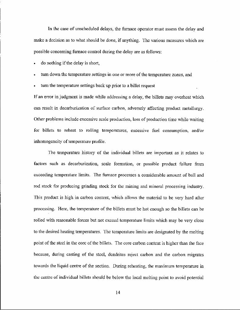
cracking problems. Centre-line melting may adversely affect the rolling operation
downstream of the reheating process. Figure 2.8 shows the effect of increased carbon
content on the melting temperature of the steel [2]. It is clear from the iron-carbon phase
diagram that the melting temperature of steel decreases with increasing carbon content for
the range in which we are concerned.
Figure 2.8 Effect of Carbon Content on Steel Melting Temperature
15
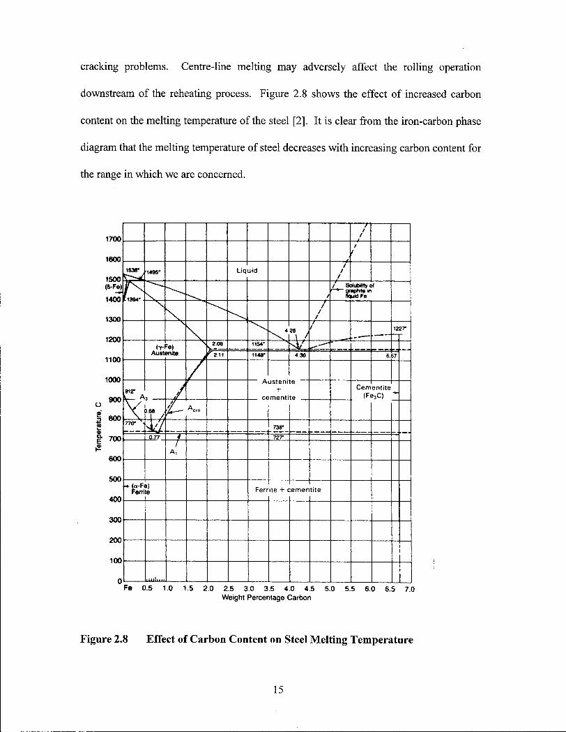
Decarburization is the loss of carbon from the local composition of the steel due
to high temperature diffusion [8]. When mild steel is heated to temperatures below
910°C, the surface layer of ferrite does not allow substantial diffusion of carbon due to
the very low solubility of carbon in ferrite. Above 910°C, the solubility of carbon in
austenite is high enough to allow nontrivial diffusional movement of carbon from the
steel substrate into the combustion atmosphere. Figure 2.9 illustrates the outward
migration of carbon from the steel to combustion atmosphere. Although the movement
of carbon is not instantaneous, care must be taken to avoid extended exposure to a
combination of time and high temperatures. The actual decarburization rates are
dependent not only on time and temperature but also on internal temperature profiles,
metallurgy and furnace gas composition. Figure 2.10 illustrates the effect of time and
temperature on surface carbon content [8].
Combustion atmosphere 0 2
Figure 2.9 Schematic of the Migration of Carbon from the Steel into the Combustion Atmosphere
16
1 0 0 0 1100 1 2 0 0 1 3 0 0 TEMPERATURE , °C
Figure 2.10 Limiting conditions of time and temperature for various degrees of decarburization in 3" slab based upon isothermal data.
The extent o f decarburization can make the metal more susceptible to shear and
spalling. Figure 2.7 shows a typical heating profile for the furnace. It is possible to see
the point at which the furnace temperature reaches 910°C and carbon becomes mobile. It
is at this point that the clock starts for the residence time at temperature with respect to
decarburization.
Increasing the time that billets are subjected to high temperatures results in
excessive formation of scale. Scale is the oxidation of the Fe parent metal to FeO, Fe2C>3
and Fe3C>4 on the surface which is exposed to a hot oxidizing combustion atmosphere.
17
The amount of scale formed, much like the extent of decarburization, is dependent on the
temperature, time at temperature, billet metallurgy, and furnace gas composition. Scale
formation has been shown to decrease the tendency of decarburization but this is not
entirely an asset. Scale directly affects the bottom line, in terms of increasing the amount
of steel lost from the raw billet as final product and increasing the frequency of
maintenance down-time due to the buildup of scale at the bottom of the reheating furnace
[9]. Scale must be removed prior to rolling or it may be rolled into the final product
leading to rejections based on rolled-in surface flaws [6].
Combustion options such as running the furnace in extremely fuel rich conditions
has not proven feasible due to economic as well as operational safety issues. The only
acceptable method thus far to reduce decarburization and excessive scale production is to
minimize the high temperature exposure time [6]. Under normal operating conditions,
decarburization and scale formation are not major concerns because the billet residence
times are low compared with other reheating furnaces but this can change quickly under
conditions of long or multiple delays [10,11].
In the case of common transient conditions, the furnace operator can follow a set
of Standard Operating Procedures created by the mi l l personnel based on experience as
well as simple heat transfer and residence time calculations. In theory, the SOP must be
followed closely to ensure consistency. However, in reality, the SOP cannot account for
all possible conditions which may affect the operating efficiency of the furnace. It is
therefore the operator's experience, reasoning as well as trial and error which help bring
new knowledge to the effective control of the furnace [11].
18
Chapter 3. Expert and SCADA Systems
Chapter 3.1.Expert Systems:
Control problems which are complex and not easily discretized tend to be difficult
to quantify mathematically. It is with these control problems that an expert system can be
beneficial due to the knowledge-based nature of both the problem and solution. Expert
systems are designed to hold information in a system which enables the gathering and
organization of knowledge derived from experts in the exact manner as it is relayed to the
knowledge engineer. This knowledge then can be utilized in the form of rules and
procedures to assess problems and offer possible solutions where one may not have been
available from other control system strategies. It is therefore unnecessary to completely
analyze and understand the scientific and engineering fundamentals of all aspects of a
problem in order to produce a reasonable control regime.
The knowledge engineer is the person who may know something of the problem,
facilitating good comprehension of the knowledge, but not necessarily an expert in the
field [12,13]. It is often preferable i f the knowledge engineer is removed slightly from
the problem in order that knowledge which may be obvious to the expert is not
overlooked by the knowledge engineer [14]. The life cycle of the development of an
expert system involves five distinct stages: Problem domain definition, Knowledge
acquisition, Developmental programming, Testing and Verification [15].
The knowledge engineer must examine the scope of the problem in order to make
decisions on strategy and structure of any subsequent solution. The scope of the problem
19
must be defined in order to move towards a solution which is reasonable and attainable.
The strategy reflects the nature of the problem and directly affects the structure of its
solution. It is in these early stages that the approach to a problem must be defined prior
to any gathering of knowledge.
The knowledge acquisition phase involves the knowledge engineer gathering
information in all its forms including, interviewing experts, mathematical models, process
analysis and historical information. Knowledge can come in many forms including
Procedural, Declarative, Episodic, Semantic and Metaknowledge [12].
• Procedural knowledge is low level knowledge in the form of "know how" and is akin
to a reflex in that the procedure is repetitious to a degree that is essentially automatic.
A good example would be the procedural knowledge required to ride a bicycle.
• Declarative knowledge is often referred to as "know-how" that is easily verbalized.
This knowledge is usually very superficial and does not give insight into the
underlying knowledge which an expert may use.
• Episodic knowledge refers to knowledge in the form of temporal and spatial
anecdotes which the expert may have acquired via experimental information.
• Semantic knowledge is knowledge which contains concepts, definitions, relationships
as well as rules for manipulating this information when reasoning.
• Metaknowledge reflects the awareness of an expert in assessing how knowledge is
used to solve problems. This knowledge also includes the ability to determine i f there
is any solution to a problem.
20
Knowledge in all o f these forms, become the foundation from which a knowledge base
for an expert system is transformed into a symbolic representation usable by a computer,
or inference engine, programmed and designed to manage the knowledge units.
The system developmental programming phase involves placing knowledge into
the knowledge base in a form which allows the system to reach reasonable conclusions
based on analyzing knowledge v ia the inference engine. System development involves
the application of a "Conceptual Model" , in which the knowledge engineer [12]
formalizes the structure of expertise and can layer the knowledge in accordance with
different levels of abstraction and functionality. The conceptual model may include
domain, inference, task and strategic layers. The knowledge domain represents the static
knowledge and is made up of concepts as well as their relationships. The Inference layer
integrates the knowledge in the form of what can be done with the knowledge in the
knowledge domain. The Task layer are methods in which the inferences can be used to
achieve specific goals. The Strategic layer is the generalization of how experts move
towards problem resolution and is the most difficult knowledge to formalize [12].
The testing and verification phase involves testing the system in a real problem
situation and verifying, often with the aid of the expert, to determine that the system is
indeed providing reasonable solutions to problems [12]. It is acceptable to have experts,
in the role of devil's advocate, collaborate with the system builders in the testing phase.
These methods of verification and validation are important during system development
since it allows deficiencies in the system to be identified or [12] facets to be tuned to
provide the best possible solutions.
21
Chapter 3.2. Examples of Expert Systems:
Cement K i l n
Expert Systems have been used to control a wide variety of industrial processes in
the past. For example an expert system was implemented on the control of a rotary
cement k i ln in 1982 [1]. For cement kilns, the general practice was to control heat input
manually with an operator adjusting the burner setpoint temperature in response to gross
internal temperature changes. This process resulted in large fluctuations in process
variables which directly affected the quality of the product as well as fuel consumption.
The quality of the k i ln output is a function of the amount of clinker which is exposed to a
heating environment in the correct temperature range for a correct time-at-temperature.
Due to the long residence times within the k i ln (several hours), the time-temperature
history of one portion of charge may be different from the rest of the charge during
control incidents in which the ki ln may experience substantial temperature variations.
Therefore the narrower the heating profile, the higher the quality of the clinker product
output. A commercial expert system software package " L I N K m a n " was used as the base
for this application. L I N K m a n relied on fuzzy logic, which is the application of logic in
which information is obtained and processed along with calculated degrees of certainty.
The fuzzy logic controller provided greater control of furnace temperatures resulting in
improved product quality, decreased N O x emissions, fewer temperature excursions
within the ki ln and a reduction of 10% in fuel consumption [1]. The expert system was
successful in this case in controlling process temperatures because it was able to examine
22
complex process variables such as the varying composition of feed material, process
delays and unexpected process disturbances based on operator experience. Instruments
placed in extremely hostile environments can be susceptible to giving false readings
which simple instruments cannot adequately filter. The system was able to reduce control
errors induced by false readings created by sensor input fluctuations because it was
possible to examine the signal for validity prior to usage.
Gas Combust ion
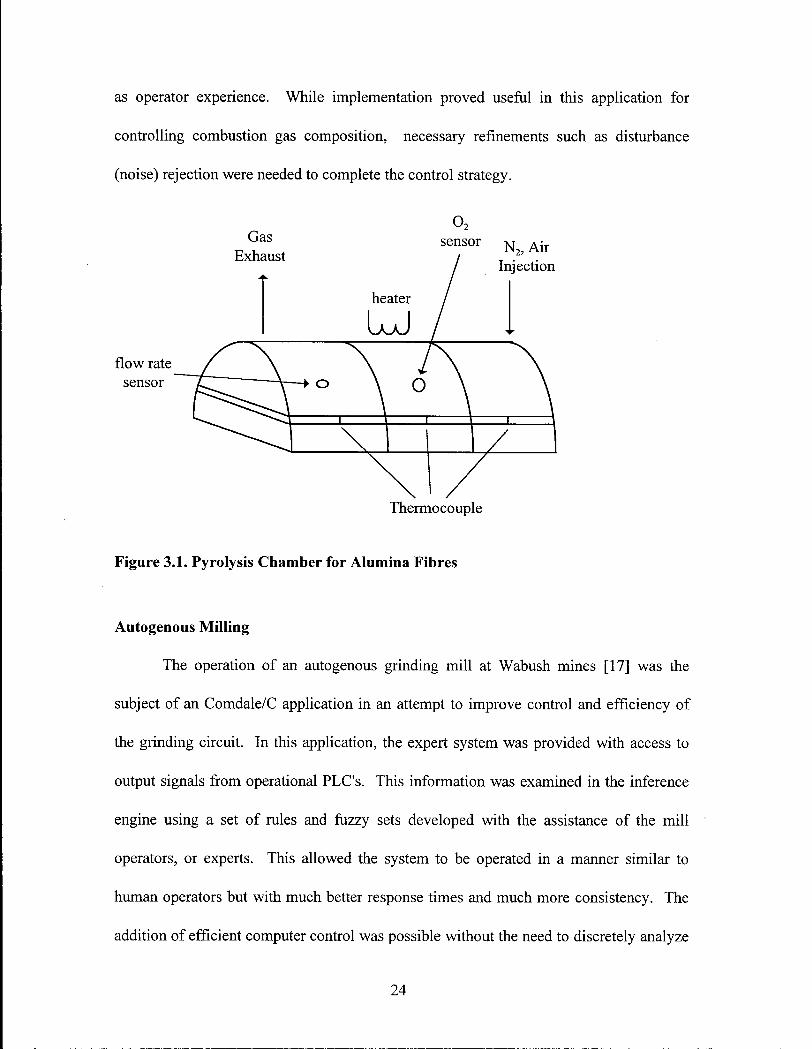
The prediction of gas composition in a combustion process can be difficult due to
the complexity of the combustion reactions under different temperatures, varying
pressures, pre-combustion gas compositions and fluid dynamics through the complex
combustion chambers. A process schematic is presented in Figure 3.1. [16]. A fuzzy
logic based controller was utilized to control the combustion gas composition in a
pyrolysis reaction of alumina fibers used in metal matrix composites. Combustion gas
composition directly affects the quality of fiber produced in this furnace therefore the
consistent control of the combustion was paramount. In this system, introducing a
complete furnace model to predict and control the operational parameters was not feasible
and had the drawback of omitting the experience of the operator. In this application, a
finite-element steady-state model of the fluid dynamics was used to define the boundary
conditions for control parameters within a safe zone which would result in good
combustion gas compositional control. These control parameters, along with rules based
on expert operator experience, were programmed into the fuzzy controller which directly
controlled the furnace mass flow valves. This system allowed for good control of
combustion gas composition via knowledge gained from the mathematical model as well
23
as operator experience. While implementation proved useful in this application for
controlling combustion gas composition, necessary refinements such as disturbance
(noise) rejection were needed to complete the control strategy.
flow rate sensor
Thermocouple
Figure 3.1. Pyrolysis Chamber for Alumina Fibres
Autogenous Milling
The operation of an autogenous grinding mi l l at Wabush mines [17] was the
subject of an Comdale/C application in an attempt to improve control and efficiency of
the grinding circuit. In this application, the expert system was provided with access to
output signals from operational PLC ' s . This information was examined in the inference
engine using a set of rules and fuzzy sets developed with the assistance of the mi l l
operators, or experts. This allowed the system to be operated in a manner similar to
human operators but with much better response times and much more consistency. The
addition of efficient computer control was possible without the need to discretely analyze
24
a complex control problem. The operation of this grinding circuit is based on the
knowledge of operation obtained from operator experience and logical analysis of the
process flow. The efficiency of the operation was increased by as much as 20% for
certain products due to the ability of the system to operate the mi l l equipment at closer
and more consistent levels to its full design potential [17].
Continuous Cast ing
The control of continuous casting of steel billets is a process, cloaked in "Process
Lore", understood well in some aspects but poorly understood in others. The control of
such processes has been left to the development of many practices based on sources such
as general casting operator experience as well as researched aspects of the process. A
process devoid of substantive knowledge can be subject to ingrained practices which,
although incorrect, can be difficult to change. It is necessary to separate useful
knowledge from the counterproductive methods based on Process Lore [18]. It is in the
essence of an expert system that the control of such a process can be quantified in such a
vast array of pertinent but sometimes contradictory factors. In the application of an off
line expert system to the process of continuous billet casting, the knowledge gathered
from research [19] and useful experience was separated from counterproductive practices.
This knowledge was accumulated and structured into a knowledge base written in the
shell Comdale/X. This implementation involved the ability to assess billet quality
problems off-line as well as offer the ability to tutor non-experts in the finer points of
proper billet casting practices [13,20]. The system was brought to the next logical step
with the implementation of the knowledge base in the form of a Comdale/C application.
Real-time and on-line applications are applications which examine process variables
25
directly and produce results which are timely to the control of the process. The
Comdale/C system allowed the expert system to operate in real-time and on-line with a
billet caster and to examine the process variables with a myriad of remote sensors
collecting trend data. This system facilitated assessment of billet quality problems before
the billet left the mould as well as offer advice to the operator on how to remedy
problems during the process operation.
While expert systems can be used to filter out noisy process data and provide
useful process trends, this may not be the most efficient utilization of the system. In
order to increase processing speed and decrease the unnecessary creation of complexity in
the expert system, a separate module to prefilter this data can be implemented. A
computational intelligence (CI) module can feed the expert system vital trend data in a
timely fashion without the need to pass all remotely acquired data. In the application of a
computational intelligence module to the expert system for a billet continuous casting
process [21], data was acquired at a rate of ~20Hz and processed through a CI module
written in a low level processing language (C) using an operating system which allowed
real-time multitasking of both the CI unit and the expert system. The marriage of "hard
code" signal processing intelligence and the "soft code" of the expert system allows for
real-time casting analysis without unnecessarily subjecting the numerical complexity of
the data stream to the inference engine. Only pertinent information gathered by the CI
modules, which may use repetitive artificial intelligence (Al ) techniques, is passed onto
the expert system for processing [22].
It is clear from these examples of expert system applications, that results can be
rewarding. Expert systems allow the collection of operational knowledge from many
26
sources to form a knowledge base. This knowledge is in a symbolic form similar to the
structure humans use in problem-solving processes. The process can therefore be
controlled in a manner similar to human operators without explicitly understanding the
fundamentals of a problem. In addition to offering more efficient control, an expert
system can standardize practices and can become a useful teaching tool for inexperienced
operators. The application of an expert system to this steel billet reheating furnace
therefore would be a logical step forward in solving some control problems.
27
Chapter 3.3.Proposed Implementation of an Expert System to the Reheating Furnace:
In reheat furnace operations, several issues are of concern. The mi l l considers
production as the primary motivation for operating the reheat furnace. In the greatest
sense of the phrase, "Time is Money", rolling mills must not be idly waiting for hot
billets from the furnace i f a profitable operation is to be maintained because of the high
overhead costs of maintaining such facilities [6]. A t the same time, product quality must
be maintained since substandard product billets can potentially lead to higher rejection
rates, or increase the extent of product downgrading after rolling. Finally, fuel
consumption is also important as this constitutes a major part of production cost in the
bottom line of the mill 's financial ledgers. With all of these issues in mind, we can
proceed in providing an educated analysis of the mi l l operation.
To understand the problem requires intimate knowledge of the cause and effect of
furnace operating procedures. Due to the slow speeds at which data is generated for a
wide array of operating conditions, long term data collection is required. Data such as
billet size, grade, product range, as well as temperatures and operator response must be
collected. In order to keep the cost of data acquisition low, the data collection platform
chosen was a PC-based system linked to the plant network in a fashion as to allow the
periodic retrieval of data as required. Figure 3.2 outlines the data collection and transfer
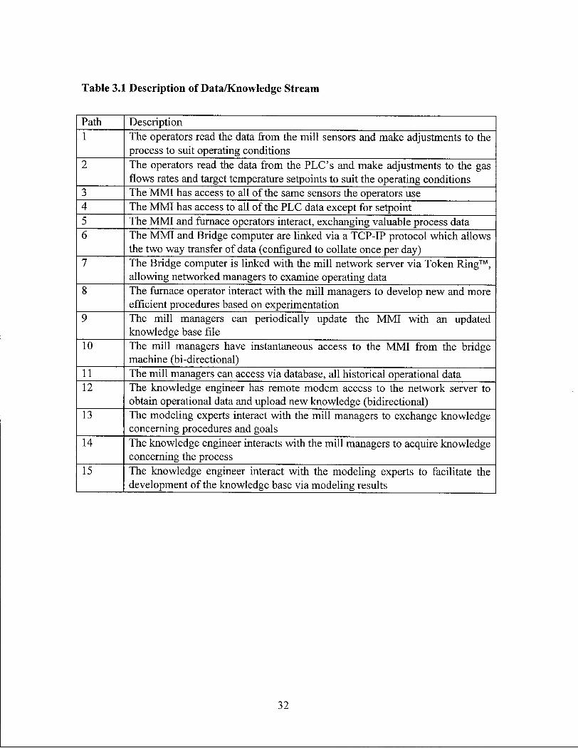
regime within this project. Table 3.1 describes the links between all o f the individual
components/players.
28
The operational knowledge used to control the furnace in the form of furnace
operators experience should be a valuable starting point in building a knowledge base.
Unfortunately, the furnace operators have created different approaches to transient
conditions and their experience under similar experience, while useful, was not consistent
enough to allow for the collection of the "best" knowledge. This "episodic" knowledge
was very disjointed and often clouded by process lore. Therefore it was not directly used
in the knowledge acquisition phase. However, a set of "Standard Operating Practices"
(SOP) by the most experienced operator, the combustion engineer, and through,
discussions with the remaining operators was created to provide congruency in operating
strategy. This agreement in the required furnace operating practices provides a fair
degree of procedural consensus [12]. The majority of this knowledge is in the form of
"declarative" and "procedural" knowledge and is considered significant because it was
carefully scrutinized by the combustion engineer. The SOP was therefore used as the
basis for the creation of the reheat furnace control knowledge base.
Several plant trials were performed in association with the modeling portion of
the Billet Reheating project. These trials involved thermocouple instrumentation of test
billets which were charged into the furnace and heated in accordance with normal
operating procedures [3]. The internal as well as surface billet temperatures were
recorded along with the three zone temperatures, zone gas and air firing rates, gas
temperature, furnace pressure, and gas composition. Information gathered from
instrumented billet plant trials along with long term data gathered from the system
allowed verification of a static as well as a 3-D transient billet furnace model developed
at the University of British Columbia [3]. This model was used in conjunction with mi l l
29
personnel to discuss the ramifications of certain operating procedures on product quality,
operating efficiency and fuel consumption. The new procedures, were intended to
become the basis of new knowledge for the Standard Operating Practices as well as an
online advisory expert system. The knowledge gained in this exercise represents both the
semantic and metaknowledge of the mi l l experts as well as the modeling experts.
The available knowledge fits well into a conceptual model. Basic knowledge,
such as the cause and effect of raising burner rates or increasing production rates make up
the knowledge domain. The inference layer is made up of how this information can be
used, such as what can be accomplished by adjusting these variables. The task layer
involves how we can use these endpoints to solve a specific problem which may not seem
to have a direct relation, such as how one would go about reducing scale formation. The
strategic layer encompasses these concepts " in the big picture" such as the approach of
using data collection and mathematical models to examine furnace operation.
Once sufficient structured knowledge of the process is gathered, an expert system
could be configured to implement control action directly based on information from the
furnace as well as operator input. Unfortunately, due to the extreme scope of such a
project, the primary goal of the system is to provide online advice to the furnace operators
whom w i l l implement the control actions based on the advice and their own experience.
The expert system w i l l be designed to allow basic knowledge to be maintained as
well as the addition of new knowledge as it becomes available. The expert system w i l l
provide timely, online knowledge-based advice through a user friendly man-machine
interface. In addition, the system wi l l create the ability for mi l l management to introduce
a standardized methodology for handling the majority of furnace transients.
30
* DOS
TZ3
Network Server
12
Q \ \
Modeling Experts
Figure 3.2 Schematic of the Data and Knowledge Streams
Knowledge Engineer
31
Table 3.1 Description of Data/Knowledge Stream
Path Description 1 The operators read the data from the mi l l sensors and make adjustments to the
process to suit operating conditions 2 The operators read the data from the P L C ' s and make adjustments to the gas
flows rates and target temperature setpoints to suit the operating conditions 3 The M M I has access to all of the same sensors the operators use 4 The M M I has access to all of the P L C data except for setpoint 5 The M M I and furnace operators interact, exchanging valuable process data 6 The M M I and Bridge computer are linked via a TCP-IP protocol which allows
the two way transfer of data (configured to collate once per day) 7 The Bridge computer is linked with the m i l l network server via Token Ring™,
allowing networked managers to examine operating data 8 The furnace operator interact with the mi l l managers to develop new and more
efficient procedures based on experimentation 9 The mi l l managers can periodically update the M M I with an updated
knowledge base file 10 The mi l l managers have instantaneous access to the M M I from the bridge
machine (bi-directional) 11 The mi l l managers can access via database, all historical operational data 12 The knowledge engineer has remote modem access to the network server to
obtain operational data and upload new knowledge (bidirectional) 13 The modeling experts interact with the mi l l managers to exchange knowledge
concerning procedures and goals 14 The knowledge engineer interacts with the mi l l managers to acquire knowledge
concerning the process 15 The knowledge engineer interact with the modeling experts to facilitate the
development of the knowledge base via modeling results
32
Chapter 3.4. Obtaining and Processing Furnace Data - The Supervisory Control And Data Aquisition (SCADA) System:
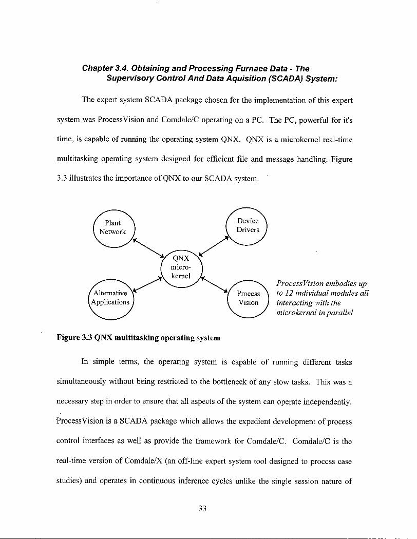
The expert system S C A D A package chosen for the implementation of this expert
system was ProcessVision and Comdale/C operating on a P C . The P C , powerful for it's
time, is capable of running the operating system Q N X . Q N X is a microkernel real-time
multitasking operating system designed for efficient file and message handling. Figure
3.3 illustrates the importance of Q N X to our S C A D A system.
Figure 3.3 Q N X multitasking operating system
In simple terms, the operating system is capable o f running different tasks
simultaneously without being restricted to the bottleneck of any slow tasks. This was a
necessary step in order to ensure that all aspects of the system can operate independently.
"ProcessVision is a S C A D A package which allows the expedient development of process
control interfaces as well as provide the framework for Comdale/C. Comdale/C is the
real-time version of Comdale/X (an off-line expert system tool designed to process case
studies) and operates in continuous inference cycles unlike the single session nature of
ProcessVision embodies up to 12 individual modules all interacting with the microkernal in parallel
33
Comdale/X. ProcessVision provides the user interface, data collection and data handling
to the system. Comdale/C is integrated with ProcessVision to provide very efficient data
and knowledge processing. Comdale/C structures knowledge into key-word-triplets
(KWTs) instead of variables. The structure of the triplet name provides insight into its
value. The three segments of the K W T are the object, attribute and value [23]. The
object indicates the piece of information the system is describing, the attribute is the
property of that object in question, and the value is the number or logical operator
assigned to the KWT. Each K W T is assigned a "degree of belief which describes a
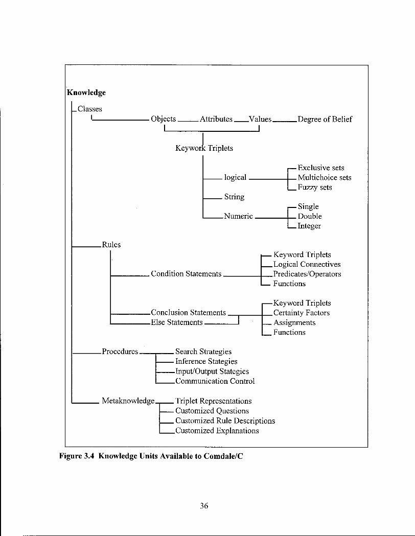
percentage assessment of the certainty of the correctness of the knowledge. Figure 3.4
displays the unit of knowledge available in the Comdale/C environment [13].
The knowledge tree structure displayed in Figure 3.4 shows that knowledge
segments which Comdale/C utilizes are discretized into four groupings. The knowledge
is in the form of structural, procedural, external and metaknowledge. The declarative,
episodic, and semantic knowledge as stated previously are defined as the Structural
knowledge which constitutes the rules and facts in the system. The significant addition to
these groupings is external knowledge which refers to knowledge available to the system
from other programs. In the case of our application, this external knowledge comes from
data acquisition drivers which convert sensor information into useful knowledge in the
form of KWTs [24]. This is the key which allows the inference engine to be brought
online to be a real-time application responding to new conditions with new conclusions.
The Comdale/C application can be separated into a series of separate modules
each given specific tasks. Although these modules all operate in the QNX environment
independently, they are linked and influence the operation of each other. This interaction
34
can be seen in Figure 3.5 [25]. Although the modules exist for completing certain
specific tasks, for the sake of user-friendliness, some module tasks were reconstructed in
a form acceptable for operator perusal. A n example of this would be the expert view
module which is a windowed running list of expert processes. This style of information
display was deemed unsuitable by personnel accustomed to retrieving information in a
format and position that does not change. As a result, an advisory screen was created
within the process view module to cement the data in consistent and predictable
locations.
The Comdale system was originally designed to operate efficiently as it controlled
processes with relatively slow reaction times. The inference engine is operated with a
one second or more cycle time which is adequate for moderately paced supervisory
control situations. The cycle times of the system must be fast enough to accurately
sample events which are critical to operation. The reheat furnace system has a myriad of
slow response inputs and one fast input. The input from the pyrometer consists of -2000
points gathered over 1-2 seconds every minute or so. This alone would make the system
unusable i f not for the inclusion of a set of high speed data collection programs operating
in parallel with the Man-Machine Interface (MMI). The data collection drivers
intelligently sample the inputs until an event is detected. After the record of the event has
been buffered internally in the driver, the data is processed and uploaded into the
inference engine at an acceptable rate. The expert system can then use the information
over the subsequent inference cycles to determine an appropriate action plan.
. Search Strategies • Inference Stategies -Input/Output Stategies .Communication Control
. Triplet Representations
. Customized Questions
. Customized Rule Descriptions
.Customized Explanations
Figure 3.4 Knowledge Units Available to Comdale/C
36
Historical Database K—• Database 4 L Event 4 k Trend
Manager 1 • Scheduler J f Manager
Point Database
Inference Engine < •
Alarm Manager H—•
Message Manager
Process Instrumentation
Knowledge Base H—•
Explainer Engine
Process View
Expert View
Figure 3.5 Independent Application Modules
3 7
Chapter 4. Scope and Objectives
Chapter 4.1.Scope of the project:
Steel billet reheating furnaces have larger thermal inertias and are rarely operated
under steady state conditions which makes control a difficult task. The delay
phenomenon is the single largest factor affecting the operation of the furnace. Delays
have the effect of creating varied temperature histories and thus differing temperature
profiles in the billets. Control of the furnace has been left up to the discretion of the
furnace operators who control heat input into crude non-independent heating zones based
on operating experience.
Inefficient operation of the furnace can result in a financial penalty for the steel
mill in terms of fuel costs, product loss, and mill idle time. The goal of furnace control
has been to focus on the production of steel billets at the correct temperature while
ignoring other variables. It is therefore necessary to develop consistent strategies for
furnace control that minimize other losses during delay situations.
Due to the nature of the problem long term data collection is necessary to obtain a
representative sample of the problem. The recording of experimental data from the mill
on a long term basis required that the system be industrially robust in terms of software as
well as hardware.
The knowledge that is used to control the furnace is in the form of experience
acquired by furnace operators; this can be difficult to quantify. A direct algorithm-based
3 8
system is therefore not feasible in this situation. In contrast, an expert system is able to
examine many different facets of a problem and produce an answer based on information
contained in a knowledge base. The information contained within our knowledge base is
made up of knowledge of the furnace operators as well as information gleaned from a 3D
transient mathematical model. This expert system would weigh the various parameters
and produce recommendations based on an embedded knowledge base.
Chapter 4.2. Objectives of the project:
The overall objective of this project was to develop a system which will increase
production, increase product quality, decrease product losses and reduce fuel
consumption by reacting to furnace delays and/or upsets which will minimize deviation
of billet temperatures. To these ends, the following is a set of necessary steps to attain
these goals.
(1) To implement an online data acquisition system to record furnace and billet data
as well as provide a user friendly interface for the furnace operators.
(2) To closely examine the delay phenomenon with respect to billet size and roll
product.
(3) Based on statistical plant data, categorize delays in terms of cause, frequency and
duration and develop case studies for some of them.
39
(4) From this basis, incorporate improved response strategies into knowledge
contained within an online real-time expert system.
(5) To validate the system by obtaining feedback from mill personnel.
40
Chapter 5. - Methodology
Chapter 5.1 .Approach to the Reheating Problem:
The furnace had been operating satisfactorily in processing the billets for the
rolling mill but mill personnel wanted to improve some specific aspects of the reheating
procedure. Delays in the production of hot billets resulted in loss of useful rolling mill
time and subsequently a monetary loss to the mill. As well, poor procedural operation
resulted in low recovery rates or product yields due to rejection as well as product
downgrading. One goal of this project was to attempt to reduce both of these factors as
well as to reduce fuel consumption.
The situation was investigated as a control problem with the major factor being
the ability to accurately predict billet requirements with lead times in the order of hours.
With this in mind, we can approach the problem with the realization that it may not be
possible to completely quantify all transient situations. The best that can be offered in an
operation in which any number of possible control situations are possible, is to
statistically isolate the most frequent transient conditions and produce a suitable response
for each case. While this is a good approach, it is also necessary to understand that the
extent of a transient may not be accurately predicable on the onset of the incident. This
has the effect of infinitely complicating the number of possible outcomes requiring a
conscious restriction of the scope of this project.
41
One of the major problems plaguing the reheating furnace is one of
standardization. In this mill, the reheat furnace is operated by four full-time operators as
well as two temporary operators. The primary furnace operators come from a variety of
backgrounds but most operators are chosen based on union seniority in the mill hierarchy
of maintenance personnel. The operation of the furnace is left to the discretion of these
mill workers who learn their skills from each other as well as some less than reputable
sources (one incident included implementation of psychic billet manipulation!).
The goal of the combustion engineer is to increase the reheat furnace efficiency.
It is believed that part of this goal can be achieved by standardization procedures used by
the furnace operators to delay situations. In order for the mill to conform to quality
standards such as ISO 9002, process control must be standardized and documented. A n
expert system would allow each operator to have access to all of the mill's standard
recommended settings and procedures deemed appropriate by documented experience
and combustion analysis.
An expert system can be used to collect as much static knowledge on the
operation of a reheating furnace as well as make timely assessments of transients based
on the "best guess" of the furnace operators..
The system must be capable of recognizing the start of a delay. Under ideal
situations, the system will be told of a delay by the operator because this allows for the
system to provide advice sooner. Unfortunately, due to the frantic nature of many delays
this option is not reliable. The system is capable of detecting a delay by intelligently
monitoring the gap times between billets and trigger a response regime i f the gap time is
a certain percentage above normal. This trigger needs to be tuned to dynamically adjust
42
the "normal" gap time as a floating average and respond only when a delay of non-trivial
duration is detected.
Upon detection of a delay situation the system flags the operator to provide an
initial estimate of the delay duration. This estimate will be provided to the system in the
form of selecting from one of three choices, short, medium, and long. The range of each
of these delays will be assigned from the knowledge base as defined by the particular
product. The system will then issue an advisory based on this input as well as
information provided by the knowledge base (SOP).
As the delay progresses, the system tracks the actual delay length to determine i f
the initial estimate was incorrect. If the delay terminates prematurely or the delay is
longer than initially estimated, the advice that was issued will not be suitable for the
situation. The system must be able to detect the aberration and issue a revised response
advisory. This advice will dynamically change based on the estimated delay time as well
as the progressive actual time.
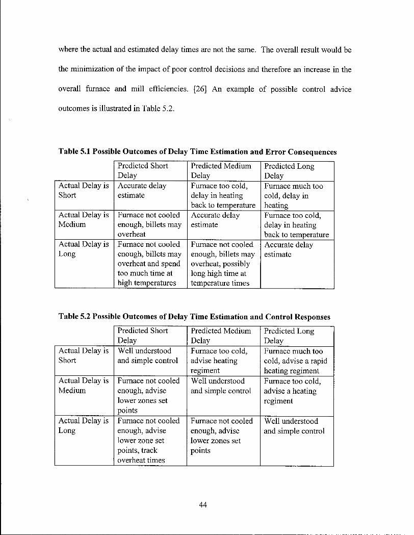
Table 5.1 displays the nine possible outcomes based on an initial three choice
estimate. Here, the subsequent advisory control response is valid for 3 of the 9 scenarios
which leaves 6 of the remaining 9 with responses which may not necessarily be
appropriate.
It is possible to create a system which can request the operator to estimate the
transient variables and produce advice based on this guess. If the estimation is not
accurate, the system can adapt itself based on operating conditions or by the operator
updating the estimation. The system can be enriched with knowledge on how to respond
to delay situations after the delay has progressed towards one of 6 remaining scenarios
43
where the actual and estimated delay times are not the same. The overall result would be
the minimization of the impact of poor control decisions and therefore an increase in the
overall furnace and mill efficiencies. [26] An example of possible control advice
outcomes is illustrated in Table 5.2.
Table 5.1 Possible Outcomes of Delay Time Estimation and Error Consequences
Predicted Short Delay
Predicted Medium Delay
Predicted Long Delay
Actual Delay is Short
Accurate delay estimate
Furnace too cold, delay in heating back to temperature
Furnace much too cold, delay in heating
Actual Delay is Medium
Furnace not cooled enough, billets may overheat
Accurate delay estimate
Furnace too cold, delay in heating back to temperature
Actual Delay is Long
Furnace not cooled enough, billets may overheat and spend too much time at high temperatures
Furnace not cooled enough, billets may overheat, possibly long high time at temperature times
Accurate delay estimate
Table 5.2 Possible Outcomes of Delay Time Estimation and Control Responses
Predicted Short Delay
Predicted Medium Delay
Predicted Long Delay
Actual Delay is Short
Well understood and simple control
Furnace too cold, advise heating regiment
Furnace much too cold, advise a rapid heating regiment
Actual Delay is Medium
Furnace not cooled enough, advise lower zones set points
Well understood and simple control
Furnace too cold, advise a heating regiment
Actual Delay is Long
Furnace not cooled enough, advise lower zone set points, track overheat times
Furnace not cooled enough, advise lower zones set points
Well understood and simple control
44
Chapter 5.2. Implementation of the Expert System:
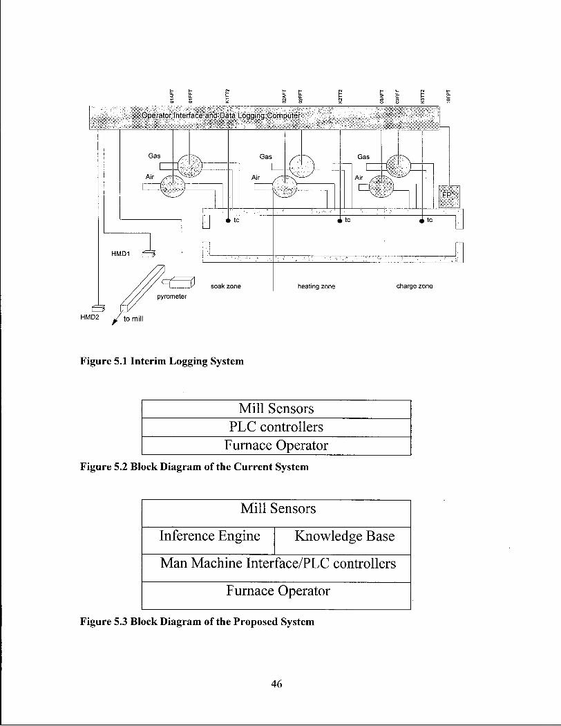
The implementation of the expert system was divided into two distinct phases.
The first was long-term data collection and logging phase. In this phase, inputs from the
furnace controllers were taken along with some inputs seen only by the furnace operator
which are compiled in daily log files. Figure 5.1 shows the control, detection and logging
system. These files were taken and compiled into the cumulative collection of files on
the plant database. These files along with hard copies of schedules were remotely
retrieved and analyzed at U B C .
The final phase of the system installation included compilation of the knowledge
base and insertion into the man/machine interface which the operators were already
familiar with. The system would detect transient conditions and provide timely advice to
the operator in both steady-state and transient operating conditions. Figure 5.2 and Figure
5.3 show the integration block diagram of the current as well as the proposed systems.
45
Operator Interface and Data Logging Computer
Figure 5.1 Interim Logging System
M i l l Sensors PLC controllers
Furnace Operator Figure 5.2 Block Diagram of the Current System
M i l l Sensors
Inference Engine Knowledge Base
Man Machine Interface/PLC controllers
Furnace Operator
Figure 5.3 Block Diagram of the Proposed System
46
Chapter 5.3. The Installed Expert System:
The expert system implementation was divided into two distinct phases. Phase I
involved installation of a data logging system which was not only acceptable to the end
users but also facilitated long term collection of furnace control knowledge. The
development of the man-machine interface was considered to be of utmost importance
due to the need for operator acceptance [12] in the development as well as creation of a
method to verify the expert system. Phase II of the project involved completing the
assembly of the knowledge base as well as installation of the advisory functions of the
man-machine interface.
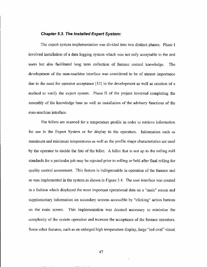
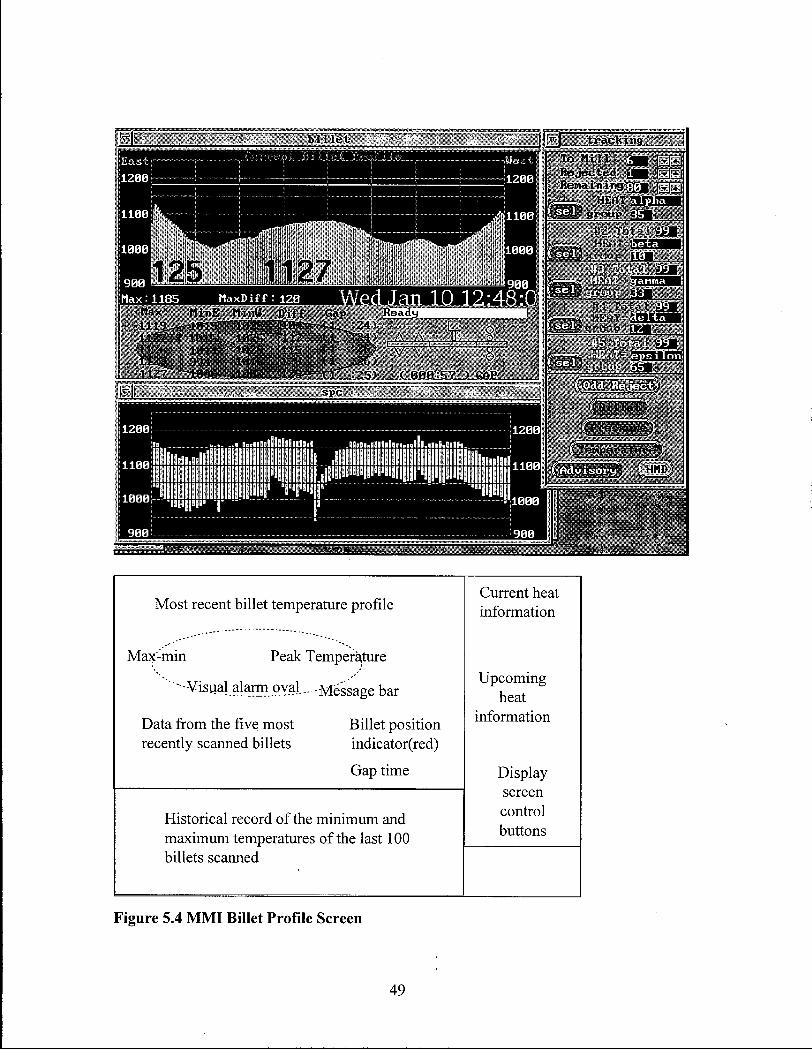
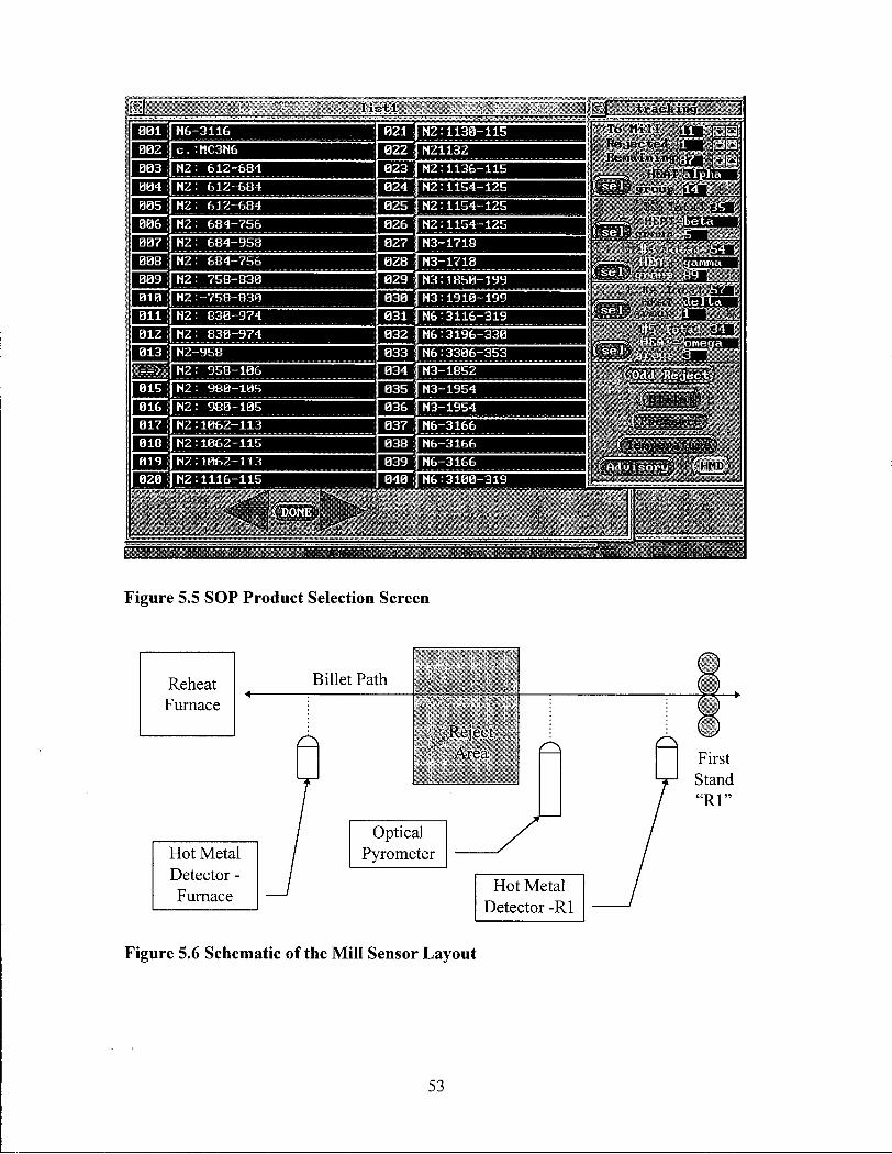
The billets are scanned for a temperature profile in order to retrieve information
for use in the Expert System or for display to the operators. Information such as
maximum and minimum temperatures as well as the profile shape characteristics are used
by the operator to decide the fate of the billet. A billet that is not up to the rolling mill
standards for a particular job may be rejected prior to rolling or held after final rolling for
quality control assessment. This feature is indispensable in operation of the furnace and
so was implemented in the system as shown in Figure 5.4 . The user interface was created
in a fashion which displayed the most important operational data on a "main" screen and
supplementary information on secondary screens accessible by "clicking" action buttons
on the main screen. This implementation was deemed necessary to minimize the
complexity of the system operation and increase the acceptance of the furnace operators.
Some other features, such as an enlarged high temperature display, large "red oval" visual
4 7
indicator of an alarm condition, and a schematic "billet position indicator" for
determining the billet location, were also added to increase the degree of user acceptance.
48
Li 'c t i k i m j
J ll«J 1127 * IBIS
-1 i z f , ' i n n 1123 Q94 1127 l e w ;
M i n u r i i n u i ) i t r
1825 " "'112 I
10B2ll i l lH
G a p
£1 "• 11 t l t l " " .
s p c
24)
.26) 2b>
1208 1288 ii: ..a • • t l l l l l l l l l l l l l l l t l . I l t l i . l l l l l l l t i • OS i l l . • i i l . l i l l i . 1
1 1 0 e l lIl!i i i i . , e | i l l lIIl l l l!IIIII!IIll l l l!i .llllllllllllllllllllllllllllllllllllllll m i 1 1 0 0
Illllllllllllllllllllllllllllllll'llllllllllllilUlli " i l l l l l l ' l l l i l l l l i l l l l l l l l l l l lHI 1 1 0 0
lBBBj "j" " §1 >il808
T o M i l ] i__ __t
R e j e c t e d H E L t l R e m a i n i n g -m r^jjj
..— HEfti a \&E$D g r o u p «
— .- • ' ' . • V -
Most recent billet temperature profile Current heat information
Max-min Peak Temperature
" - V i s u a l alarm oval.... Message bar Upcoming
heat
Data from the five most Billet position recently scanned billets indicator(red)
information
Gap time Display screen
Historical record of the minimum and maximum temperatures of the last 100
control buttons
billets scanned
Figure 5.4 M M I Billet Profile Screen
49
Traditionally, the furnace operators were accustomed to having a historical
display of the billet minimum and maximum temperatures as each are scanned by an
optical pyrometer prior to movement towards the rolling mill. This trending information
visually allows the operator to "learn" from his own successes as well as mistakes. This
episodic knowledge is useful in the development of general control trends but can be
tainted by "process lore". An operator can look at the consequences of his actions in
terms of the decisions made in the relatively distant past. Although this delayed learning
process is useful, the complexity of furnace operation makes a simple cause and effect
determination very difficult. This feature was important enough to include and is shown
in Figure 5.4. Note that the information which has been deemed important in terms of
trending information is the profile minimum and maximum temperatures because these
two criteria affect the ability of the rolling mill to process the billet.
In addition to the main screen, the operator has access to a heat-tracking screen.
A "heat" represents a batch of steel which has been cast through the continuous caster and
is usually specific in terms of chemistry, thermal history, and as-cast quality. A change
in heat therefore represents a change in the input billets, which may also lead to a change
in the rolled products therefore affecting the furnace operating conditions. If the change
in operating conditions is substantial, the procedures for handling the transient from one
heat to the other may be very different from the steady-state operating conditions of either
heat. In the past, the operators have had to manually keep track of the heats as they
entered and exited the furnace.
50
The heat tracking strip, as shown on the right of Figure 5.4 shows a system in
which the operator is able to enter the current heat name as well as the next 4 heats along
with all pertinent heat information. The billet heating and furnace operating parameters
are selected from the SOP list as illustrated in Figure 5.5. This information is used by the
operators but is also a great help to the expert system in terms of knowing the future
charges in the furnace. This implementation of the automatic billet tracking was difficult
due to the nature of the signals received from the mill (see Figure 5.6).
A billet released from the furnace is seen by the first detector but not necessarily
by the pyrometer and the second detector. The furnace operator may choose to reject the
billet before or after the pyrometer. The pyrometer may see multiple scans of the same
billet which can lead to a miscount. The furnace may drop more than one billet which
will not register as two discrete billets prior to buffering in the reject zone before rolling.
These signal inputs must be examined via a rule structure which attempts to deduce the
actual events in the mill with a high degree of certainty. The expert system can quite
accurately determine the position and condition of a billet with the use of the three
available sensors and a set of rules based on the conditions outlined in Figure 5.4. Due to
the difficulty of being absolutely certain of the result, the system can sometimes
misinterpret the activity, therefore the operator has been provided with the ability to
manually correct the count on the MMI .
In addition to these logistical problems in signal interpretation, noise generated by
the Hot Metal Detectors (HMDs) frequently result in false readings. These readings are
filtered via a CI module, feeding the expert system a billet discharge signal only i f one
has likely occurred. A schematic of an ideal signal as well as examples of noise which
51
may affect event detection is illustrated in Figure 5.7. The low level driver program
acquiring the signal from the mill, filters the signal and only issues a billet passage
condition when it has most likely occurred. The inference engine performs a secondary
determination of billet passage by means of a weighted averaging of the signal over time.
This weighted average is tuned by the operators to ensure the highest degree of accuracy.
The pyrometer signal is also filtered by the drivers to prevent noisy peaks from
affecting the profile which is displayed and recorded. In addition to the filtering process
the driver extracts information such as a minimum temperature for each half of the billet,
maximum temperature and maximum temperature difference.
The implementation of the billet accounting feature alone was sufficient to
convince the furnace operators to abandon the older system and use the new one. The
older system was allowed to remain online so the operators had a transition period in
which they could become accustomed to the new interface and procedures.
In addition to the main screen interfaces, several auditing screens were provided
which offer trends of furnace pressure, zone firing rates, and zone temperatures. These
screens contain data which the system logs to daily files but is left in a form that the mill
combustion engineer can examine on-site without having to download data to a graphing
program in the mill offices. This data is useful in assessing operator performance and
compliance to the SOP as well as providing a firing history necessary to predict the
conditions of billets to be released. Figure 5.8 and Figure 5.9 show the screens as
captured from the mill computer during a Phase II visit. This screen along with the mill
database of operating condition changes proved the most useful tools in encouraging
compliance amongst the operators to the SOP.
52
l i s t l N 6 - 3 1 1 6
c . - n C 3 N 6
H 2 : 6 1 2 - 6 8 4
N 2 : 6 1 2 - 6 8 4
N 2 : 6 1 2 - 6 8 4
N 2 : 6 8 4 - 7 5 6
N 2 : 6 8 4 - 9 5 8
N 2 : 6 8 4 - 7 5 6
N 2 : 7 5 8 - 8 3 0
N 2 : - 7 5 8 - 8 3 0
N 2 : 8 3 0 - 9 7 4
N 2 : 8 3 0 - 9 7 4
N 2 - 9 5 8
HZ: 9 5 8 - 1 0 6 N 2 : 9 8 0 - 1 0 5
N 2 : 9 8 0 - 1 0 5
M 2 : 1 8 6 2 - 1 1 3
M 2 : 1 8 6 2 - 1 1 5
H 2 : 1 0 6 2 - 1 1 3
N 2 : 1 1 1 6 - 1 1 5 u n a
N 2 : 1 1 3 8 - 1 1 5
N 2 1 1 3 2
N 2 : 1 1 3 6 - 1 1 5
N 2 : 1 1 5 4 - 1 2 5
N 2 : 1 1 5 4 - 1 2 5
N 2 : 1 1 5 4 - 1 2 5
N 3 - 1 7 1 8
N 3 - 1 7 1 8
N 3 : 1 8 5 0 - 1 9 9
N 3 : 1 9 1 0 - 1 9 9
N 6 : 3 1 9 6 - 3 3 0
N 6 : 3 3 0 6 - 3 5 3
N 3 - 1 8 5 2
N 3 - 1 9 5 4
N 3 - 1 9 5 4
N 6 - 3 1 6 6
N 6 - 3 1 6 6
N 6 : 3 1 8 0 - 3 1 9
T o M i l l Ri i j tsc t i A Hi-n.t i II i i i i j ;
, I IEAT"S VfcfMay g r o u p i
[ ( P r e s s u r e )
. ( I e w p e y a t u r e )
• f l S & f a r i l iHMD*
HUT
Figure 5.5 SOP Product Selection Screen
Reheat Furnace
Hot Metal Detector -Furnace
Figure 5.6 Schematic of the Mill Sensor Layout
53
Table 5.3 Possible Detector Signal Sequences
Event Conditions #1 - Billet successfully passed from the furnace to the rolling mill
The sequence is: H M D - furnace, optical pyrometer, and H M D - R l
#2 - A billet was rejected after scanning
The sequence is: H M D - furnace, optical pyrometer, optical pyrometer and the next is not H M D - R l
#3 - A billet was rejected before scanning
The sequence is: H M D - furnace, with no optical pyrometer within ~10 seconds
#4 - Double drop - two billets were released
The sequence resembles #1 except the following is: optical pyrometer, H M D - R l for the next billet
#5 - A billet is removed from the system with the overhead crane
This occasional event does not have a sensor sequence that can be discretized, therefore a manual correction on the system is provided for the operator
C L E A N SIGNAL Voltage
Time
Voltage
NOISY SIGNAL
High Limit - Signal is above designated levels
Spike - Short duration noise
Time
Low Limit - Signal is below designated levels
Figure 5.7 Hot Metal Detector (HMD - an optical position sensor) Signal Quality
54
i l l d i f f e r e n c e
C h a r g e Z o n e F l o u s
0 9 : 0 8 1 0 : 0 0 1 1 : 0 0 1 2 : 0 0
H e a t i n g Z o n e F l o u s
0 9 : 0 0 1 0 : 0 0 1 1 : 0 0 1 2 : 0 0
S o a k Z o n e F l o u s
4 "
- 0 . 0 6 " H 2 0
C h r g _ G a s
: V | . t r a c k i n g j
T o M i l l J£ j TjTj; R e j e c t e d Rr-rM i n i n g
_ ^ H E A T i P R g r o u p nm
1 0 / 0 1 • 9
0 . 0 4 " H 2 0
H e a t G a s
fieit m r 0 "
4 " ' '
0 . 0 4 " H 2 0
S o a k G a s
1 0 / 0 1 / 9
A , i :.t.
1 4 ? u i . i ;
11111 i I o n
f B i l l e f ; (Preasur.eJ
ifTenpdra-turej D E L A Y
Trend-line of gas and air flow into the charge zone
Current heat information
Upcoming Upcoming 1 heat Trend-line of gas and air information flow into the heating zone
Display screen
Trend-line of gas and air control buttons flow into the soak zone
control buttons
Figure 5.8 Historical Furnace Operation Screen - Gas Flows
55
1 3 0 8 . 8 9 8 3 . 0 0 C 5 0 0 . 0 0 C } i r g _ T e n p
t »• ic k Micf
T o tTTTi [T -
R e j e c t e d £] R e n a i n i n g risM
— p , M K A T
1%) g r o u p ffsg
(i®&flfcl!EiS? HUD
8 9 : 8 8 1 8 : 8 8 1 1 : 8 8 1 2 : 0 8
r " 1 3 0 0 . 0 1 1 6 5 . 0 C 5 0 0 . 0 0 H e a t _ T e t m p H e a t i n g Z o n e
1
1 3 0 0 . 0 1 1 6 5 . 0 C 5 0 0 . 0 0 H e a t _ T e t m p
Phase II of the project included installation of the knowledge base containing
knowledge from past procedures of the plant as well as recently altered procedures. This
phase also included installation of an advisory screen which the operator is prompted to
read during transition or transient-operating conditions. The screen, as shown in Figure
5.10, shows a typical product recommendation along with an area in which the operator
can prompt the system to provide advice, once a delay has been detected, based on the
operator's estimation of delay length.
advisory
F i l l s " N n . |M/l: OGU R.B. | P i n i s l i « ; < l L i : n < i t l , | | S h a p i : |
i B i l l u t | M J : <.HJU WLZ l U i l l c - L L e n g t h | L £ U " 1 l - 0 " I C r a r t u | .JHH . I H H . 4 H M K .
UPPT.II iiTi«jM|Ri:ironr.iNn rsnn IBM.I'.M̂RM,/™, WMIRI UI .um iwti i us id" ! 1 .
P r a t t . i i : i ; :!["M"2: 9 5 8 ~ 1 B 6 ~ H e a t : II * ' " p h a " __ - H . i x Ti:ni> 1 1 7 H C i
M a x D i f f I H H t: ! F u r n P r e s . 1 3 0 " " U C
' , i • ' 'isEE8££§> ! ' B H ™ a R E A L •CiSMJ ^ S a ^ J M S C p 1 I B B - 1 3 0 0 s e c G A P :
G r u m i : 14 ' M W U x ' l W J 2HHH -M2HH : : H H , , i a M S e t
S o a k 1 i i L - j L t : C h a r g e O O O X 0 0 0 0 0 0 0
0 0 0 0 0 o oj 0 0 0 0
0 0 0 0 0 o o' 0 0 0 0
o o oj X 0 0 0 0 0 0 0
1 ' 4 0 , nr,R
• " L O U C A M I O N S T E E L O N L Y UITII A P R A C T I C E NUMBER I K f i H H H 0)1 L 0 U E K " ? ? T ( 1 ) : SOAK S O N E : S e t control t o Maintain r o l l i n g tenperature: C>:): H E A T « (-IIAHGE Z O N E S : S e t , : m i l i - . i l s t o " H " output: l-" HIRNCif I P R I S M I K I . S i t ..1 H HUH ' C 4 ) : " A L L S T K E L U I T H A P R A C T I C E NUMHKK A l k H ' E Ill'fiHHW MUST U S E T H E "
" D E L A Y MANAGEMENT THE S A M E A S H I G H ' f iHH' . 'N . Hfi l . I . S T O C K . L i t I N h I N u K O l i : ;
? ! * " H I L L K T S Ml 1ST BE C E N T R E D I N THE F U R N A C E " ! ? ?
Figure 5.10 Advisory Screen
57
The expert system provides advice in the form of static advice as well as advice
based on the condition of a delay. If the operator has made an estimate of the delay
length, the system will provide the appropriate information to handle the situation. If the
time of the delay is longer or shorter than the prediction, the advice changes to suit the
situation based on knowledge added to the system previously. This screen, while not
prominent, does allow the operator to retrieve advice from the system as required and
perform operation changes in accordance with current operating procedures. The advice,
i f not followed may result in a poor heating condition which the combustion engineer can
address after the fact. If the change in procedure has a good effect on billet heating, the.
combustion engineer has the option to assess the situation and change the procedures
accordingly. This is the strength of the system, in that the intuitive skills of the operator
can be merged with standard procedures to optimize reheating and therefore increase mill
efficiency.
The strength of an expert system is its ability to handle a vast amount of
knowledge in a form which is not necessarily linear. This allows an expert system to
operate with any number of rules and procedures. Of course the more information
available to the system, the more reliable the deductions become. However, this non
linear nature makes the completion of sequential tasks cumbersome since the
sequence of events can sometimes be quite random. Our system required that many
events be completed in very specific sequences in order to maintain logical order in
basic file/data "housekeeping" tasks. The ability of Comdale/C to invoke sequential
procedures aided in this task but did not solve the problem of larger sequential tasks.
A series of flags were therefore established to enable and disable rules within the
58
knowledge base which only allow certain procedures and rules to be active when
required. The expert system implementation therefore ran on a very large inference
cycle which was able to spawn a series of child cycles for accomplishing certain
housekeeping tasks. The large inference cycle is slaved by a series of internal flags to
allow the ordering of certain sequence sensitive tasks. Figure 5.11 outlines the main
inference cycle along with some of the more interesting child cycles. It is important to
note that although this flow chart seems to operate in a directed sequence and flow
like a typical computer program, the flow is quite non-linear. The result is a form of
controlled chaos which, of course, is similar in many ways to human thought.
On startup of the expert system, a large number of key-word-triplets (KWTs)
must be initialized with a set of starting point values. This is necessary to ensure that
the system child processes can be enabled and the ProcessVision man-machine
interface is setup for display. This is a simple procedure in which a series of
Comdale/C procedures are enabled only once prior to being disabled for the duration
of the system's operation. Due to the sequential and mundane nature of the static
knowledge, most of this information is stored not in rule form but in the form of data
files on the Q N X machine. During startup, a series of C programs which are in
themselves child processes, are summoned to glean important knowledge base
reference data from the files and compile a product profile with a series of K W T
arrays.
During normal operation, a series of housekeeping child processes are
periodically invoked which themselves may call on other child process within the
Comdale/C environment or in Q N X level processes. Table 5.4 lists the housekeeping
59
processes and conditions in which they are active. In normal operation, the advisory
portion of the knowledge base is filled with static knowledge based on the input billet and
output product. In a delay situation, the system enables the advisory segment associated
with the tracking of delay time and dynamically adjusts advice based on user input and
actual sensor readings.
60
LOAD
BOP HEAT
CHANGE
BILLET
ACCOUNTING
MANUAL
REJECT
PYROMETER
(timestamp)
0) o >. o T3 C o o <D 03 CD C o I Q. o O _ i LU O z LU CC LU
EXPERT ADVICE ARRAY
short-short short-med short-long
med-short med-med med-long
long-short long-med long-long
FLAG OPERATOR
DISPLAY ADVICE
CASCADE
GAP TIMES
PYROMETER
HMD
FURNACE
HMD
LOAD
BILLET
BUFFER
UNLOAD
BILLET
BUFFER
Figure 5.11 Inference Logic Cycle applied to the Knowledge Base
61
Table 5.4 Child Processes Within the Inference Engine
Process Purpose Effect Temperature Alarms
Watch for static as well as product based temperature violations
The operator is flagged and the event is logged in the data files
Week Day Check
To break the log files into day long files for transfer to the mill network
Weekday named files are assembled into a 2 week buffer zone which is uploaded to the mill network nightly
File Annotizer To create a log file of all furnace operational data
Every 30 seconds all pertinent furnace data is saved to a daily temp file
Gap time calculator
To keep track of billet falls A gap time for the last billet to present time is updated every second until another billet fall
Furnace H M D detector of a billet event at the furnace
Increments the billet tracking buffer until a conclusion can be made of the event detected
First stand H M D
detector of the billet event at the entrance of the first set of rolls
Indicates the billet leaving the sphere of detection of this system. A conclusion is drawn on the events to determine the probable fate of the billet(s)
Pyrometer " H M D "
To indicate a billet event at the pyrometer (internal signal)
Adds to the location logic information that a billet may be moving towards the first stand but makes no deduction until another event is logged.
Pyrometer time stamp
To use the pyrometer as the line at which the gaps are tagged
A l l gap times are based on the billet registering an event at the pyrometer.
Manual reject Operator correction mechanism
In certain rare cases, the three detectors can not deduce the correct event. This allow the operator to manually correct the event error
Billet Accounting
To track billets As events are reduced to actual billet movement the accounting is done in the heat tracking and the billet is logged to a billet event log file
Heat Change Heat changes may affect furnace operation
As a heat change is detected by internal flags, the subsequent heats are chained forward and all pertinent operational knowledge is upload from data files.
Delay detection Internal delay detection invokes a response from the system to prepare advice
A delay is detected, and the system prompts the operator to ask for operational advice based on the operators estimation of delay duration
62
Chapter 5.4. Analysis of the Furnace Operation Data:
In an attempt to understand the delay phenomenon, it is necessary to collect
as much statistical data as possible relating to as many delay conditions as possible.
The furnace, for control purposes, is separated into three independent zones. Of
course each of these zones is not explicitly independent as the temperature in one
zone greatly affects the temperature in the others due to the open design geometry.
The three furnace zones are controlled separately with three feedback loops. Each of
the zones uses a thermocouple as the primary sensor of furnace temperature. The
temperatures of the zones are converted near to the type "R" thermocouples from the
millivolt reading into a 4-20 mA signal which is much more resistant to stray
electrical interference. The milliAmp signals are read by three programmable logic
controllers (PLC's) which adjust the gas and air flow to the individual zones in order
to increase or decrease the zone temperatures. The amount of air and natural gas fed
into each zone is detected with a slide-wire feedback loop connected to the servo-
mechanisms which control the valve openings.
The control of these zones follow basic PID principles in order to obtain target
temperatures with a minimal time delay and temperature oscillation. The target
temperatures are selected by the furnace operators based on historical operational data
as well as current mill demand. Measured variables such as temperature, gas and air
flows therefore provide invaluable amounts of information on the typical operation of
the furnace in both steady-state and transient conditions. The operating information is
63
essential for the modeling portion of this project as the model will provide the new
knowledge to the process. Due to the nature of the data, statistical trending must be
employed. Long term delay and response data on furnace must be examined in order
to seek out frequent scenarios as well as typical responses prior to proposing changes
based on the mathematical model. The magnitude of the data collected in the data
logging regime resulted in a complex process analysis problem. Typical monthly file
sizes are in excess of 100 Megabytes which made traditional data analysis techniques
too cumbersome to be feasible. To address this problem, a series of low level
programs were written in F O R T R A N to scan the data files and retrieve relevant
information or look for trends. This information was used to create a statistical
picture of the furnace operation and control responses for subsequent model analysis.
The procedural flow of this analysis is delineated in Table 5.5.
64
Table 5.5 Reheating Furnace Control Procedure Analysis
Knowledge Engineer Billet Operating Procedure Identification retrieve logged data files
• retrieve heat sheets • Billet size (from heat sheets) . Rolling M i l l Product (from heat sheets)
Knowledge Engineer
Data Extraction Input Date/time band parameters
• Extract logged data from the master files
Knowledge Engineer
Gap Time Plot Analysis • plot gap times • identify frequent delay times
Knowledge Engineer
Scenario Generation • Input gap sequence key
extract response data extract profile data
Modeling Experts Process Modeling Model responses Pose Alternatives
• Model Alternatives Assess results
Knowledge Engineer M i l l Experts
Validation • Propose changes in procedure to the mill • Assess Changes on-line • Add Changes to the Knowledge Base
65
Chapter 5.5. Analysis of the Optical Pyrometer Data:
After reheating, the hot billets are discharged from the furnace to a conveyor
system where the scale is removed using a high pressure water descaling box. The
billet is then moved past the viewing window of a scanning optical pyrometer. The
pyrometer determines the temperature of an object based on the amount of infrared
energy radiated from the object in accordance to a calibration of emmisivity factor.
The scanning optical pyrometer provides a temperature profile along one side of the
billet (usually the trailing side). As the billet drops from the discharge chute onto the
conveyer system, it may perform a quarter turn which brings the bottom face to the
view of the pyrometer. The majority of the pyrometer scans therefore are of the side
of the billets. However, it is not uncommon for the billet to rotate randomly to show
a different face to the pyrometer and give a more or less severe apparent skidmark
(refer to the Statistical Process Control-SPC on Figure 5.4 to see the discontinuity in
the data band). The billets move along the conveyer at a relatively consistent speed
determined by the particular weight and friction with the rollers which generates a
good representation of the profile but not the absolute length of the bar. This profile
is provided to the furnace operators in real-time and provides an instant assessment of
the suitability of the bars for use as well as a post-operational assessment of the past
operational procedure. This information is the only tangible feedback the operators
use. Information which is gleaned from this profile includes maximum temperature,
maximum difference in temperature as well as skidmark severity. In terms of
66
statistical delay analysis, the pyrometer data is vital since it is also a good indicator of
a billet release from the furnace. The time between billet releases is known as the gap
time and statistical analysis of the gap times pinpoints frequent scenarios. This data is
then used to extract furnace operational data which gives an insight into typical
operator responses.
Chapter 5.6. Analysis of the Billet Groupings:
The mill bars can be classified into a number of groupings based on bar size,
metallurgy as well as product. The bar sizes include the three billet classes N2, N3,
and N6 representing square sections of 4.5", 8", and 10" respectively. These are
section sizes which do not include the section length, a statistic which affects overall
heat input required to raise the billets to a target temperatures. Chemistries in which
the main classifications are based on carbon content and other alloying elements,
outline the heating limitations. Billet chemistries for products such as ball and rod
stock is extremely temperature sensitive and overheating can result in product
rejection or even cracking of the billets inside of the furnace.
The product for which the bar is rolled can affect the groupings as target
temperatures and pacing rates can be constrained by rolling rate rather than heating
rate. M i l l personnel indicated that roughly 40% of the production is rolling mill
constrained, leaving the remaining 60% of the bars running the furnace at full
capacity. Control of the furnace under the furnace constrained conditions is relatively
straightforward if the furnace is run at full capacity and billets removed as soon as the
67
temperatures are within rolling specifications. It is during the 40% of production in
which the process is constrained by the rolling mill in which the system is useful in
furnace control.
In order to restrict the possible scenarios, grouping of gap times are obtained
from the statistical analysis of gap times for products with similar product rolling
procedures and temperature requirements. With these gap time groupings, it is then
possible to extract furnace operating conditions in steady-state as well as transient
conditions. Based on these operating procedures, it is then possible to select not only
the most common responses but also responses which may have had a good or bad
effect on billet quality. It is from these responses that the mathematical model can be
utilized to optimize the furnace operating responses under various steady-state and
transient conditions.
68
Chapter 6. Results and Discussion:
Chapter 6.1. The Expert System:
As is quite often the case, delays can be hectic situations in which the ftirnace
operator may become too occupied with delay related tasks to inform the system that a
delay has occurred. Therefore, the system has been given the ability to determine the
existence of a delay based on the examination of a series of sensor signals. Delay
detection is based on the expert system examining the sequence and timing of the three
detector signals available to the computer. The sequence is analyzed and a delay is
flagged internally as well as externally in the form of a flashing button offering advice to
the operator. The advice is offered in a manner which is as non-invasive as possible, the
operator needs only to "click" on the advice button to summon the advisory screen
containing recommended procedures. The system is currently stocked with declarative
and procedural knowledge from the Standard Operating Practices as well as new
knowledge from scenario "role playing" using the U B C transient furnace model. This
knowledge forms the basis for the expert system in terms of providing the operator with
knowledge gathered and refined from years of experience and from recent developments.
When the knowledge based is stocked with appropriate responses pertaining to complex
delay situations, the system will be able to offer timely advice for a myriad of transient
operating conditions in addition to the current static knowledge.
Statistical analysis of the delay data collected over the period of approximately
one year has lead to the isolation of a few statistically significant delay situations.
69
APPENDIX H contains a sunimary of 6 weeks of furnace operation. Of the three billet
size products, it was possible to identify three major categories of delays. In order to
illustrate these categories, an example of arbitrary grouping of N6 gaps times is shown in
Figure 6.1. The actual gap times between billets in shown on the horizontal axis and the
actual number of billets released is shown on the vertical axis. It is evident from these
plots that the three delay groupings can be extracted. The short, medium and long delays
were identified as discernible groups. It is possible to rearrange the delays into arbitrary
ranges and change the scale to focus on statistically frequent ranges. Also, i f we remove
billets which were released on schedule, the groupings become much more evident
(Figure 6.2).
With this in mind, it was possible to retrieve operator control responses to each of
the delay categories. Due to the nature of the data and the lack of details such as delay
cause or overlapping transients, the only feasible approach in addressing these scenarios
was to choose the most frequent delay responses. The system records and archives time-
stamped temperature profiles of the billets for scrutinization. Furnace operating data was
also available to the modeling experts. Figure 6.3 illustrates the zone temperature records
which can be correlated with the billet temperature data. In addition to these traces, gas
flows, air flows, and total furnace pressure stemming from operator control of the PLC's
is shown in Figure 6.4, Figure 6.5, and Figure 6.6 respectively. A n example of the
historical billet temperature profiles is illustrated in Figure 6.7.
The responses can then be analyzed via the mathematical model to determine the
efficiency of the operator's responses as well as the possibility of creating better response
without the need to experiment with the actual furnace controls. The analysis can then be
70
expanded to include theoretical responses to incorrect initial responses based on
inaccurate initial operator delay estimates. This information can then be placed into the
expert system to provide timely new advice as an initially misdiagnosed delay progresses.
Work on different aspects of transient procedural modeling continues.
It had been believed that roughly 40% of the production is rolling mill
constrained, leaving the remaining 60% of the bars operating the furnace at full burner
capacity. Logged furnace operational data from the data provided for model
scrutinization by Osinski showed that this was not that case in that not all of the zones of
the furnace were under heavy firing condition with the large 8" billets. Again the manner
in which the furnace is operated may have been affecting the furnace throughput. Further
examination of these procedures is required to assess the feasibility of increasing furnace
throughput by altering some of the ingrained operating procedures with this new
knowledge. Details of the scenario modeling performed by Osinski are included in
APPENDIX A. It is clear from this example of mathematically modeled delay response
strategies, that the expert system can becomes more effective with the addition of
externally generated knowledge.
71
700 - r
600 -
500 -
i r > o > c o r ~ - i - m c > < o r ^ - < - i o a > o o p - T - i o a > c o c o o c o r ~ - o c o r - ~ o - s r i - ~ o ^ i - r ^ T - ^ i - r ~ -T - T - r - C M C M C M C O C O C O ' ^ - ' ^ ' ' ^ - i r ) l f ) m
Gap time (sec)
Figure 6.1 N6 Raw Gap Times
Gap time (sec)
Figure 6.2 N6 Gap Time with Arbitrary Ranges
72
1400
1200
1000
800
600
400
200
M [I V
Charge zone - Heat zone -Soak zone
4-CO co CO co CM CM CM ro •0- o CO CO o CM in O CM <b 1— CO cb 66 o O CM o CO m CO CM OO CO ur> in <b CO 1
•— 1— 1— *— T— —̂ Temperature (°C)
Figure 6.3 Example of Furnace Zone Temperature Traces
Figure 6.4 Example of Furnace Natural Gas Traces
73
Figure 6.5 Example of Furnace Air Traces
Figure 6.6 Example of Furnace Pressure Traces
74
Time
Note: This example contains a 7.5 minute delay midway through the time sequence.
Figure 6.7 Plot of Billet Temperature Profiles Over Time
75
Chapter 6.2. The Interface & Operator Response:
The initial response to Phase I of the installation was with great reluctance on the
part of the operators due to the belief that mill management intended to replace the
furnace operators with a computer control system. This is consistent with the
"Feigenbaum Bottleneck" which includes reluctance from experts due to the fear of "loss
of work" from the A l technology, etc. [1,14]. These fears were alleviated by carefully
demonstrating and explaining the system to the operators thereby clarifying the objectives
of the system. Since the goal of the system was to supplement the tools the operators
have in their "toolboxes" for determining appropriate operating procedures, this initial
task was easily accomplished. The operators soon began to favour the new system over
the older data collection system in that the interface allowed the operators to see
information not previously available. Since the bulk of the development of the man-
machine interface was completed over a three week period, the operators were able
interact with and critique the interface during system development. This interaction
allowed the development of a system which was not only useful and acceptable to all four
primary furnace operators but also consistent with the goals of both the mill mangers as
well as the system developer. The interface ergonomic factors were therefore deemed
important for system acceptance which directly affected the level of cooperation required
during the development and implementation phases [12].
Phase II of the installation was essentially a seamless addition to the interface.
A l l of the screens of Phase I remained intact with interfaces which the operators had
76
become accustomed to and readily accepted as useful. Phase II added a single advisory
screen which provided advice, based on the knowledge within the newly installed
knowledge base and delay detection rules. As expected, this phase was the portion of the
project most difficult to obtain general furnace operator acceptance. This reluctance is
due mainly to the nature of furnace control in the past in which operators were allowed to
implement any control procedure which seemed to produce billets during minimal mill
delay. These control decisions often produced billets at the price of product quality or
production. However, since the expert system goals were the same as the supervising
combustion engineer, this reluctance will eventually be overcome. Of the four operators,
one individual wanted no interaction with the advisory screens whatsoever due to
reservations over the content of the SOP. Two of the operators were mostly indifferent
but curious as to the advice that the interface would offer. The fourth operator was very
keen on the concept and was quick in manipulating of the system and examining the
information. Unfortunately, the knowledge base was not complete at the time and only
procedural and declarative knowledge as well as relatively new knowledge generated as a
result of the mathematical model were integrated into the system. This fact alone may
explain the less than overwhelming response to the advisory portion of the S C A D A
system, however the groundwork for a completed knowledge base has been laid. The
ability to implement all aspects of the system however are active and the tools required
for future updates to the system were provided to the rolling mill managers.
A recent visit to the mill to check on the condition of the S C A D A system has
resulted in a few revelations. The older A S Y S T system has been removed and the U B C
M M I was operational as the sole window into the furnace operation. M i l l personnel
77
lauded the system as being extremely useful for both the operators as well as allowing
detailed analysis to be performed by both U B C and mill personnel [10]. The billet
tracking system however was not in use which also precludes the use of the expert
advisory system except as a reference for the static knowledge of the system. This
situation may be a result of operators' reluctance to perform the task or in part to an
increase in the inaccuracy of the billet pass determination module of the system due to
some changes in the furnace operation. The detection rules were designed to be tuned to
the specific timing of the billets from detection at the furnace H M D , the leading edge of
the pyrometer signal and the H M D at the first stand. This leads to the confirmation that
an expert system, to be useful, must be maintained and updated regularly as process
changes occur.
The relative compliance of the operators to the mill SOP is still at low levels, as
the logged data suggest. Any improvements which are made to the SOP are therefore
moot i f the operators are not held accountable to the procedures. The expert system has
been instrumental in identifying the low level of compliance but has not been useful in
encouraging compliance due to the need to bring the knowledge base up to date. The
ability of the mill personnel to monitor the compliance levels of the operators is
unfortunately still a forensic task due to the lack of a fast network link from the S C A D A
system to the plant network. This problem could not be addressed due to some plant
standardization issues but may now be surmountable i f the networking problem is
championed by mill personnel. It is the opinion of the author that a "champion" at the
mill for the system addressing the networking issue would make the system viable in this
78
particular application and push the system towards encouraging fruitful standardization in
furnace control procedures [14].
During this recent visit to Edmonton, it was determined that it is the intent of the
mill to implement a level II PLC based system which will remove the operators from the
furnace control loop. This would in turn, remove the U B C S C A D A system from the
control loop, and all the expertise contain within its knowledge base. While this would
indeed create an absolutely standard response to predetermined transients, the expertise of
the operators would be lost.
79
Chapter 6.3. Benefits of the System to the Mill Operation:
The implementation of an expert system to the billet reheating furnace was a
success. Some of the benefits can be directly measured in terms of money saved from a
decrease in product rejections, and others indirectly in terms of the introduction of order
to a sometimes chaotic process. Some of the features which were implemented into the
system which may not have been available or as refined in previous systems are:
1. Billet tracking system - to allow an automatic accounting of billet progress.
2. Real time data collection at high frequencies - low level CI drivers which collect data
and perform simple processing of data.
3. Development of standardized on-line operating practices for delays - knowledge from
different sources was compiled into a standardized knowledge base to be used by the
furnace operators.
4. Temperature profile displays - graphical representation of temperature profiles in real
time along with alarms and trend information.
5. Presentation of historical data - Trend information on temperature, air flow, fuel flow,
billet temperatures, and furnace pressure is available for on-line inspection of
operating procedures.
6. Generation of data files - Data files containing information of furnace activity and
conditions is stored for retrieval by external applications.
80
Chapter 7. Conclusions
This project has involved an examination of the problems involved in the control
of a steel reheating furnace at an Alberta mini-mill. On completion of the project the
following conclusions can be made:
• The control of billet reheating furnaces has proven to be a challenging problem well
suited to Expert Systems due to the heuristic nature of the problem.
• A Expert System consisting of a data collection module and advisor module was
developed and successfully installed at the Alberta mill. This system was still in
operation 3 years after installation. This implementation can be considered a success
due to the continued use by the mill.
• The static and transient furnace models developed by the billet reheating project were
effectively used to study control conditions and procedures leading to the
development of some new knowledge, increasing mill efficiency. This new
knowledge was assimilated into a S C A D A system.
• The system allows creation of an operating standard in which inexperienced or
undisciplined operators use proven procedures designed to increase productivity and
decrease operational losses.
• The system has proven itself as a useful tool to operators which benefit from the man-
machine interface as well as the mill managers as they attempt to improve the
operating bottom line via process efficiency.
81
BIBLIOGRAPHY
1. J.Efstathiou, "Expert Systems in Process Control", Harlow: Longman 1989, p. 114-138
2. H.E.Boyer, T.L.Gal, "Metals Handbook - Desk Edition", American Society for Metals, Metals Park OHIO, Sep 1992, p 28.2
3. P.V.Barr, K.E.Scholey, E.Osinski, Unpublished work in progress, Modeling of Steady-State and Transient Billet Furnace Operation, -1997.
4. K.E.Scholey, PhD Thesis - "A Transient, Three-Dimensional, Thermal Model of a Billet Reheating Furnace", U B C , 1996
5. J.K.Brimacombe, I.V.Samarasekera, E.B.Hawbolt, P.V.Barr, "Microstructural Engineering: Mathematical Models and Measurements to Link Steel Products and Processes", Steel Product-Process Integration, Halifax, Aug 1989. Canadian Institute of Mining and Metallurgy, pp. 147-167
6. W.J.Stry, J.D.Felske, "On Reheat Furnace Temperature Uniformity and Decarburization", 31st Mechanical Working and Steel Processing Conference, Chicago, Oct 1989, Iron and Steel Society, pp 603-616.
8. "Decarburization: Proceedings, Conference of Decarburziation", Sheffied England 1969
9. P.Agrawal, Private Communications, Spring 1993 "Expert: Ivaco", U B C
10. Dennis Gutknecht, Doug Ostafichuk, Bob Pugh, Peter Barr, Edmund Osinki -Private Communications, April 4, 1997 Edmonton "Experts: U B C and Alta"
11. Dennis Gutknecht, Doug Ostafichuk - Private Communications - Combustion Engineer, M i l l Engineer, summer 1995 "Expert: Alta"
12. L.Boullert, A Krigsman, R.A. Vingerhoeds, "Application of Artificial Intelligence in Process Control: Lecture Notes Erasmus Intensive Course", N Y Pergamon Press, 1992, p. 127-141
82
13. S.Kumar, J.A.Meech, I.V.Samarasekera, J.K.Brimacombe, "Knowledge Engineering an Expert System to Troubleshoot Quality Problems in the Continuous Casting of Steel Billets", I & S M September 1993, pp 29-34
14. J.A.Meech, " A l Applications in the Mining Industry into the 21st Century", A P C O M X X V Conference, Brisbane, May 9-14, 1995, p. 95-96
15. D.N.Chorafas, "Knowledge Engineering: Knowledge Acquisition, Knowledge Representation, the Role of the Knowledge Engineer, and Domains Fertile to Artificial Intelligence Implementation", New York, N Y , Van Nostrand Reinhold 1990, p. 20
16. Mark K Ekblad, Tamara L Artim., "Application of Fuzzy Logic Control of Gas Composition in a Combustion Process", 2nd IEEE Conference on Control Applications. Sep 13-16 Vancouver BC
17 K.McDermott, P.Clyde, M.Hall, C.A.Harris, "Expert System for Control of No.4 Autogenous M i l l Circuit at Wabush Mines. C M P P:roc.,1992, No.24,pp20-
18. J.K.Brimacombe, "Empowerment with Knowledge Toward the Intelligent Mould for the Continuous Casting of Steel Billets", 76th Steelmaking Conference, Dallas Texas, USA, Iron and Steel Society pp.3-27, 1993
19. I.V.Samarasekera, J.K.Brimacombe, "Application of Mathematical Model for the Improvement of Billet Quality", Steelmaking Conference Proceedings, Vol 74 Washington, D.C., Iron and Steel Society, 1991,pp 91-103
20. Sunil Kumar, MASc Thesis, "An expert system to Diagnose Quality Problems in the Continuous Casting of Steel Billets", 1991 (PhD 1996)
21. V.Rakocevic, J.A.Meech, "Computational Intelligence in a real-time S C A D A system to monitor and control continuous casting of steel billets", IFSA '95 Sao Paulo, Brazil, July 22-28, 1995
22. J.C.Bezdek, "What is computational intelligence", - Computational Intelligence -Imitating life, 1994 IEEE World Congress on Computational Intelligence (WCCI),pp 1-12
23. "ProcessVision 4.2 Operation Manual", Comdale Technologies, Toronto Canada, 1995
24. V.Rakocevic, MASc Thesis - "Development of a S C A D A system to Monitor and Control Continuous Casting of Steel Billets",, U B C 1995.
83
25. J.A.Meech, C.A.Harris, "Expert Systems for Gold Processing Plants", Randol Gold Forum , Vancouver march 25-27, 1992
26. Dr. John Meech, Dr. Peter Barr - Private Communications, summer 1995 Vancouver" Expert and Knowledge Engineer, U B C "
27. Edmund Osinski - Private Communications, Work in Progress - -spring 1997 "Expert: U B C Model"
84
APPENDIX A Mathematical Modeling Results
The Mathematical Model:
The vast amount of data and information gleaned from the furnace with the U B C
S C A D A system as well as data gathered from plant trials in Alberta and the pusher-type
furnace at M R M located in Manitoba allowed the tuning and verification of the U B C 3D
transient billet furnace model. The model is an offline tool necessary for running a
number of "what i f scenarios in an attempt to improve the efficiency of the furnace.
Given the good degree of confidence with the results obtained from the model, we were
able to make some recommendations to the mill in terms of operational conditions.
Figure A - 1 shows the Model Calculated (lines) vs. Experimental points (symbols) [4].
1400
billet discharged from furnace
0 20 40 60 80 100 120 Time (min)
Figure A -1 Plant Trial Results as Compared with Modeling Results
85
These recommendations allowed reduction in the number of rejections as well as a
reduction in the degree of product downgrades in temperature sensitive products such as
ball and rod stock. Following mill assessment of the procedural changes, they were
assimilated into the plant's Standard Operating Practice which is an integral part of the
operational knowledge base of our real-time advisory expert system. This change has
allowed the creation of new knowledge as well as the mechanism to translate these new
procedures to the mill level. The result of such new procedures and standardizations was
to increase the levels of Quality Assurance for mill bar products. The furnace operational
analysis of this specific scenario and subsequent system implementation has proven to
have saved the mill in the order of $100,000 with the change of the procedural operating
target temperature for rolling of ball stock [11].
In regards to "process lore", a common belief of the mill was that after delay
transient conditions, the first two billets discharged from the furnace would be cold, and
well below target temperature. The modeling of this situation by Osinski [10,27] did not
show any cold billets at the end of delay transients. There was, however some evidence
of cold billets at the end of longer delays from SCADA system logged data. Discussions
with mill personnel and further modeling of the soak zone, revealed that a combination of
the cooling effect of the exit door, the geometry of the zone and operator decisions
resulted in colder billets. The discharge door was essentially a black body which acted as
a heat sink near the discharge end of the furnace. In addition, some cold air moved
through the seal of the door which cools the billet as well as diminishing the heating
effect of the row of burners over the end billets. If the burner output is increased to
86
account for this cooling the next set of billets (5th or 6th) is overheated. As a result, the
furnace operators under-burned the zone, leaving colder billets to be discharged at the end
of longer delays. It had been believed that this feature was solely the result of cooling
from the door and the inability of the furnace to supply enough heat to the soak zone.
As a result of the dissolution of this particular piece of process lore, the control of
the furnace can be better understood and control practices can reflect this new knowledge.
Barr [10] suggested making procedural changes such as shutting down the second row of
burners in the soak zone for temperature sensitive product or possible creating a new
control zone in the furnace which would separate the soak zone into smaller control
sections.
Steady state and transient work by Barr and Osinski [10] suggest that the furnace
is not optimally operated in terms of transfer of heat from combustion into the billets.
For a large amount of the products, the charge zone is fired hard with the heating zone
idled and soak zone used only for final temperature targeting. This procedure has
allowed the operators to control the temperature with little loss in production. However,
firing the charge zone heavily also means that most of this sensible heat exits the furnace
quickly through the stack. If the heating zone were to be fired heavily, the heat of
combustion would not only be absorbed in the heating zone but also in the charge zone
which in turn would not need to be fired as heavily to maintain temperatures. The
drawback of this procedure may be in the production rate of the furnace because the heat
flux into the billets as viewed from the furnace axial profile would be skewed from the
charge towards the heating zones. The result may be a reduction in the maximum pace
rate due to the longer heating and homogenizing times. This may have the effect of
87
lowering the throughput of the furnace which may be more detrimental than the excess
fuel consumption. Work on this aspect continues, as it may be possible to maintain
throughput and reduce fuel consumption when reheating billets which are not bottle-
necked at the furnace.
It was determined via gas flow data traces that the amount of excess air supplied
to the burners under delay driven idle conditions varied to a large degree. This variation
can lead to a change in an adverse furnace atmosphere and increase the degree of scale
formation. This loss due to scale can be absorbed into the costs of delays but can be
detrimental in the production of grades with particularly adherent scale. It has been
proposed that the burning ratios be raised into a more stable region and the heating profile
in the furnace be redistributed to allow a zero net change in heat input. This would
decrease the extent of scale loss during delay conditions though better furnace
atmosphere control [10,27].
A set of "typical" delay scenarios were obtained from mill as selected from the
historical log files, including recommended responses. These were analyzed by Osinski
with the use of the U B C model to determined their effectiveness. While the procedures
had merit, it was clear that improvements could be made to these procedures. Osinski
postulated possible new procedures and tested a number of variations. The result was a
set of new post delay procedures which the model deemed as more effective. Osinski
assembled a set of results from the modeling efforts which included the examination of
the effectiveness of three delay strategies as follows:
1.. null strategy - no action is taken during or after this delay
88
2. basic strategy - as is currently prescribed
3. fine strategy - fine adjustments to the operation during and after the delay
The firing strategies noted above are summarized in Table A - 1 and Table A - 2
[10,27]. The modeled outcomes of these strategies is summarized in Figure A - 1 and
Figure A - 2 Results of a Basic Strategy with a Null Strategy
[10,27]. It is clear from these results that the null strategy as expected produces greatly
overheated billets and that the fine control strategy produced billets with much lower
standard deviations. These procedures have been presented to the mill for validation
prior to assimilation into the mill SOP.
Table A - 1 Basic Post-Delay Firing Strategy
Charge Zone Heat Zone Soak Zone [Nm3/h] [Nm3/h] [Nm3/h]
delay (70 min) 280 280 280 1st 10 min. after delay (70-80 min) 280 280 150 next 20 min. after delay (80-100 min) 1850 280 150 next 5 min after delay (100-105 min) 1850 280 400 steady state 1850 900 400
Table A - 2 Fine Post-Delay Firing Strategy
Charge Zone Heat Zone Soak Zone [NmVh] [Nm3/h] [Nm3/h]
delay (70 min) 280 280 280 1st 10 min. after delay (70-80 min) 280 280 150 2 n d 10 min. after delay (80-90 min) 1850 280 200 3 r d 10 min. after delay (90-100 min) 1850 280 200 4 t h 10 min. after delay (100-105 min) 1850 280 300 105-140 min 1850 900 300 140-150 min 1850 900 400 150-155 min 1850 900 600 steady state 1850 900 400
89
1260
1241
1220
1100
1060
—0— fins strateg —A— nuD strategy —0— fins strateg —A— nuD strategy
L i . \ tsar
O 2D 40 60 80 100 120 140 160 180 200
time [mln]
Figure A - 2 Results of a Basic Strategy with a Null Strategy
90
The steady-state and transient modeling has clearly proven itself to be a powerful
tool in the understanding of furnace operation and has added new knowledge to a often
misunderstood process. It is evident that further work along the same lines would
provide invaluable process knowledge. It also follows that this knowledge, i f
implemented in the expert system, would provide the floor level personnel with same
level of control expertise without the burden of explicitly understanding the fundamentals
behind the new knowledge.
91
APPENDIX B Hardware
Mill Computer: (The U B C unit was essentially identical in configuration but not manufacturer) • I B M Value Point • 486DX2-66 • 16 Megabytes Memory • 340 Megabyte Harddrive • Mouse, Colour monitor, Keyboard
This particular hardware configuration was selected in order to provide the minimum required hardware processing power. The actual computer was an I B M value point machine chosen by the mill in accordance to mill specifications for standardized computers. This selection, however provided an unexpected operational problem. The DAS-20 data acquisition card did not function properly due to inability to control the data stream transfer rates between the motherboard and the DAS-20. Generic computers of this age are equipped with CMOS adjustable transfer rates which readily allowed the BUS to be adjusted to match the transfer rates acceptable to the DAS-20. The solution to this problem proved to the removal of the I B M BUS riser card, which was IEEE standardized, and the installation of an A T BUS standardized riser card to make the hardware change in the BUS transfer rates.
Data Acquisition Card: • DAS-20 - Keithly Metrabyte
This card was selected for use in this project as well as the "SmartCast" project in order to provide not only the necessary acquisition rates and accuracy but also to standardize the software drivers necessary to operate these cards within the Q N X operating environment. Due diligence in the selection of this card was performed by Vladimir Rakocevic.
Networking: • Token Ring network card • Serial data line-TCP-IP protocol
Networking of the QNX furnace computer with the mill computer proved to be an effort restricted again by mill standardization. The mill operated all of their networks off an I B M token ring standard. The software allowing this option was not available until the end of the this project, therefore a temporary option was chosen. A serial line was installed from the Q N X machine to a bridge machine which transferred the daily log files from the QNX machine to the DOS machine once a day prior to sending the information onwards to the mill network for compilation with the database of operating variables.
92
APPENDIX C Software
DOS 5 - A small DOS partition was installed to allow this machine be twinned and interchangeable with another plant machine in case of hardware or software failure.
Q N X 4.21 operating system - This software was selected due to it's ability to provide real-multitasking on the industrial scale.
QNX-windows interface - This software provides the Graphical User Interface necessary for a the expert system software to operate.
Comdale ProcessVision, Comdale/C - The process view and expert system software combination which provided the man-machine interface with the furnace operators. The version of the software used was in B E T A form and required some additional low level drivers to solve some operational deficiencies
Signal Conditioning Software - this is the small CI module which examines the incoming signals from the HMD's and determined the existence of a "real" or "ghost" signal, Author Vladimir Rakocevic and Cliff Mui
U B C - data acquisition drivers - low level drivers which acquired data from the DAS-20 card performed some CI manipulations of the data stream prior to passing the relevant data onto the expert system. Authors Vladimir Rakocevic and Cliff Mui
Networking software - QCP Serial software purchased as a "Band-Aid™" solution to the networking deficiencies, This allows a DOS machine to act like a Q N X terminal logging onto the Q N X server and retrieve data files via FTP and Telnet protocols -Developed by MultiMips Software
Data processing software - small drivers designed to be evoked by the expert system to provide data to the expert system on demand as well as perform data file manipulation onto the bridge machine
Data interfacing software - DOS based scheduling software running DOS scripts that moved the data from the bridge machine to the mill network
Statistical Processing Software - Low level software written to extract information from data files of unmanageable size (> 100MB). Author Cliff Mui
Mathematical Model - 3D steady state model designed to verify the steady state operation of the reheating furnaces. Author and Expert Dr. Peter Ban-
Mathematical Model - 3D transient furnace model designed to used the data trends to determine the efficiency of control procedures. Author and Experts Dr. Peter Barr, Dr. Kenneth Scholey, Edmund Osinski.
93
APPENDIX D Plant Trials
1. K.Scholey, C.Mui, P.Wenman conducted plant trials at Alta Feb 28-Mar 1994 examining Transient and Steady-State furnace control conditions.
2. K.Scholey, C.Mui, P.Wenman conducted plant trial at Manitoba Rolling M i l l (MRM) examining Transient and Steady-State furnace control conditions, collected delay information, June 6-10, 1994
3. C.Mui, V.Rakocevic, and N.Walker installed a S C A D A system at Alta steel, interviewed personnel and collected data, November 27-December 19, 1994
4. C.Mui performed the installation of Phase II at Alta, Summer of 1995.
5. C.Mui, P.Barr, E.Osinski met with D.Gutknecht, D.Ostafichuk, B.Pugh at Alta to discuss new knowledge and inspect the M M I . Apr 3, 1997
94
APPENDIX E Data Processing Code The following is a series of small DOS programs developed in F O R T R A N to
examine the large data files obtained from the mill:
C file=iclip.for Cccccccccccccccccccccccccccccccccccccccccccc C C Ver 1.0 June 23, 1995 C This code is was written clip billet ID C data from fine Billet ID data files. C Ccccccccccccccccccccccccccccccccccccccccccccc c
INTEGER SEC,LINE INTEGER D A T E , ST A R T D ATE,FINI S H D A T E INTEGER START,FINISH INTEGER TOMILL,REJECT CHARACTER*8 TIME,START_TIME,FINISH_TIME,LABEL C H A R A C T E R * 10 N U L L
C LINE = 0
C C INPUT R A N G E F R O M CONFIG FILE C
OPEN(UNIT=3,FILE='ICLIP.CFG') READ(3,*) START_DATE,START_TIME READ(3,*) FINI S H D ATE,FINI SH_TIME CLOSE(UNIT=3) DATE=START_DATE TIME=START_TIME C A L L CONVERT(DATE,TIME, START) D ATE=FINI SH_D A T E TIME=FINISH_TIME C A L L CONVERT(DATE,TIME,FINISH)
C 202 FORMAT(I8,',',A, ,,',I3, ,,',I2, ,,',A,';,I9)
IF (DATE.NE.9) THEN GOTO 100 ELSE ENDIF CLOSE(UNIT=l) CLOSE(UNIT=2)
C END
C C ccccccccccccccccccccccccccccccccccccccccccccccccccccc ccccccc c C SUBROUTINE FOR CONVERTING D A T E A N D TIME TO abs-seconds C
SUBROUTINE CONVERT(DATE,TIME,SEC) C H A R A C T E R * 8 TIME INTEGER D A T E , S E C , B L A N K , B A S E INTEGER DD ATE,MONTH,D A Y,INDEX( 12) C H A R A C T E R * 1 HOURl,HOUR2,MrNl ,MIN2,SECl ,SEC2 INDEX(1)=0 INDEX(2)=2678400 INDEX(3)=5097600 FNDEX(4)=7776000 INDEX(5)=10368000 FNDEX(6)=13046400 INDEX(7)=15638400 INDEX(8)= 18316800 INDEX(9)=20995200 INDEX(10)=23587200 INDEX(11)=26265600 INDEX(12)=28857600 INDEX(13)=99999999
C C ABS-SEC-CONVERSION
96
c DDATE=0 B A S E = 0 IF(DATE.GE. 19940101. AND.DATE.LE. 19941231 )THEN
ENDIF M O N T H = INT(DD ATE/100) D A Y = DDATE-MONTH* 100 IF (MONTH.LE.0.OR.MONTH.GE. 13) THEN
M O N T H = 13 D A Y = 9 SEC = 999999977
ELSE HOUR1 =TIME(1:1) HOUR2 = TIME(2:2) MINI = TIME(4:4) MIN2 = TIME(5:5) SEC1 =TIME(7:7) SEC2 = TIME(8:8) SEC = B A S E SEC = SEC + (ICHAR(SECl)-48)*10+(ICHAR(SEC2)-48) SEC = SEC + (ICHAR(MINl)-48)*600+(ICHAR(MIN2)-48)*60 SEC = SEC + (ICHAR(HOUR1)-48)*36000+(ICHAR(HOUR2)-48)*3600 SEC = SEC + (DAY-1)* 86400 SEC = SEC + INDEX(MONTH)
ENDIF B L A N K = ICHAR(SECl)-48 IF (BLANK.LE.0 .AND.BLANK.GE.9) THEN
SEC = 999999988 ENDIF END
C file=stats.for Cccccccccccccccccccccccccccccccccccccccccccccccccccc C C Ver 1.0 may 23, 1995 C This code is was written to compile statistics C of data files from alta steel using 100 points C and write a data file containing these stats
97
c Cccccccccccccccccccccccccccccccccccccccccccccccccccc c
INTEGER TEM(800) INTEGER G A P , B A R S , F L A G INTEGER NUMBER(800),PERIOD(800) INTEGER MIN(800),MAXI(800) INTEGER MIN_E,MEST_W,MAX INTEGER SEC,T,X,SECJBUFF,LINE INTEGER DATE,DATE_BUFF C H A R A C T E R * 8 TIME,TIME_BUFF
C LLNE = 0 S E C - 0 BARS = 1 DO 500 X=l,200
PERIOD(X)=0 MIN(X) = 0 MAXI(X) = 0 NUMBER(X)=0
500 CONTINUE C C INPUT C C
OPEN(UNIT=3,FILE='STATS.CFG') C C R E A D IN CONFIG FILE C
300 READ(3,*) PERIOD(BARS) IF (PERIOD(BARS).NE.-9) T H E N
READ(1 ,*) DATE,TIME,(TEM(T),T=1,100),MLNJE,MIN_W,MAX,SEC GAP = SEC - SEC_BUFF LINE = LINE + 1
98
C S T A R T S T O C K I N G B A R S C
F L A G = 1
D O 4 0 0 X=1,BARS I F ( G A P . G E . P E R I O D ( X ) ) T H E N
F L A G - X
E N D I F 4 0 0 C O N T I N U E
P R I N T * , D A T E , T I M E , L I N E , S E C , G A P , F L A G N U M B E R ( F L A G ) = N U M B E R ( F L A G ) + 1 M I N ( F L A G ) = M I N ( F L A G ) + M I N J E M A X I ( F L A G ) = M A X I ( F L A G ) + M A X
C C
I F ( D A T E . N E . 9 ) T H E N G O T O 100
E L S E E N D I F C L O S E ( U N I T = l )
C O P E N ( U N I T = 2 , F I L E = ' S T A T S . T X T , , S T A T U S = ' U N K N O W N ' ) W R I T E ( 2 , * ) L I N E , B A R S W R I T E ( 2 , * ) ' G A P , F R E Q , M I N , M A X ' D O 600 X = 1 , B A R S
I F ( N U M B E R ( X ) . N E . O ) T H E N M I N E = M I N ( X ) / N U M B E R ( X ) M A X = M A X I ( X ) / N U M B E R ( X )
E L S E M I N _ E = 0 M A X = 0
E N D I F
W R I T E ( 2 , * ) P E R I O D ( X ) , , ; , N U M B E R ( X ) , ' , , , M I N _ E ; ; , M A X 6 0 0 C O N T I N U E
C L O S E ( U N I T = 2 ) E N D
C file=gaps.for Cccccccccccccccccccccccccccccccccccccccccccccccccccc C C Ver 1.0 June 2 1 , 1995 C This code is was written to compile gap statistics
9 9
C of data files from alta steel using 100 points C and write a data file containing these gap stats C Cccccccccccccccccccccccccccccccccccccccccccccccccccc c
INTEGER TEM(200) INTEGER GAP INTEGER SEC,T,SEC_BUFF INTEGER D A T E C H A R A C T E R * 8 TIME
C WRITE(2,*) DATE ,7 ,T IME ,7 , SEC ,7 ,GAP PRINT*, GAP
C IF (DATE.NE.9) THEN
GOTO 100 ELSE ENDIF CLOSE(UNIT- l ) CLOSE(UNIT=2) END
C file=Fclip.for Cccccccccccccccccccccccccccccccccccccccccccc C C Ver 1.0 June 23, 1995 C This code is was written clip furnace C date from furnace data files. C Ccccccccccccccccccccccccccccccccccccccccccccc
100
c INTEGER SEC.LINE INTEGER D A T E , S T A R T D ATE,FINI S H D A T E INTEGER CTEMP,HTEMP,STEMP INTEGER CSET,HSET,SSET R E A L CGAS,HGAS,SGAS R E A L CAIR,HAIR,SAIR,FPRESS INTEGER START,FINISH CHARACTER*8 TIME,START_TIME,FINISH_TIME
C LINE = 0
C C INPUT R A N G E F R O M CONFIG FILE C
OPEN(UNIT=3,FILE='FCLIP.CFG') READ(3,*) START_DATE,START_TIME READ(3,*) FINISH_DATE,FINISH_TIME CLOSE(UNIT=3) DATE=START_DATE TIME=START_TIME C A L L CONVERT(DATE,TIME,START) D ATE=FINI SH_D A T E TIME=FINISH_TIME C A L L CONVERT(DATE,TIME,FINISH)
C 202 FORMAT(I8,V,A,','J4,',',I4,V,I4,V,I4,V,I4,',',I4,','
C C ccccccccccccccccccccccccccccccccccccccccccccccccccccc ccccccc c C SUBROUTINE FOR CONVERTING D A T E A N D TIME TO abs-seconds C
SUBROUTINE CONVERT(DATE,TIME, SEC) C H A R A C T E R * 8 TIME INTEGER D A T E , S E C , B L A N K , B A S E INTEGER DD ATE,MONTH,D A Y,FNDEX( 12) C H A R A C T E R * 1 HOUR1 ,HOUR2,MIN 1 ,MLN2,SEC 1 ,SEC2 INDEX(1)=0 INDEX(2)=2678400 LNDEX(3)=5097600 INDEX(4)=7776000 LNDEX(5)= 103 68000 INDEX(6)=13046400 LNDEX(7)=15638400 LNDEX(8)= 18316800 INDEX(9)=20995200 INDEX(10)=23587200 INDEX(11)=26265600 INDEX(12)=28857600 INDEX(13)=99999999
C C ABS-SEC-CONVERSION C
DDATE=0 B A S E = 0 IF(DATE.GE.19940101.AND.DATE.LE.19941231)THEN
M O N T H = INT(DD ATE/100) D A Y = DDATE-MONTH* 100 IF (MONTH.LE.0.OR.MONTH.GE. 13) THEN
M O N T H = 13 D A Y = 9 SEC = 999999977
ELSE HOUR1 =TIME(1:1) HOUR2 = TIME(2:2) MINI = TIME(4:4) MIN2 = TIME(5:5) SEC1 =TIME(7:7) SEC2 = TIME(8:8) SEC = B A S E SEC = SEC + (ICHAR(SECl)-48)*10+(ICHAR(SEC2)-48) SEC = SEC + (ICHAR(MINl)-48)*600+(ICHAR(MIN2)-48)*60 SEC = SEC + (ICHAR(HOUR1)-48)*36000+(ICHAR(HOUR2)-48)*3600 SEC = SEC + (DAY-1)* 86400 SEC = SEC + INDEX(MONTH)
ENDIF B L A N K = ICHAR(SECl)-48 IF (BLANK.LE.0 .AND.BLANK.GE.9) T H E N
SEC = 999999988 ENDIF END
C file=case.for Cccccccccccccccccccccccccccccccccccccccccccccccccccc C C Ver 1.0 June 12, 1995 C This code is was written to compile case C studies from alta data files C and write a data file containing these cases C Cccccccccccccccccccccccccccccccccccccccccccccccccccc c
INTEGER TEM(200) INTEGER TEM_BUFF(200) INTEGER GAP,FL A G , S A M P L E INTEGER MIN_E,MIN_W,MAX INTEGER MIN_E_BUFF,MIN_W_BUFF,MAX_BUFF INTEGER SEC,T,X,SEC_BUFF,LINE INTEGER DATE,DATE_BUFF INTEGER START,END
103
C H A R A C T E R * 8 TIME,TIME_BUFF C
LINE = 0 SEC = 0 F L A G = 0
C C
202 FORMAT(I8,7 ,A,7,
14;, ' 14' 3 A ~ 3 3
' 14' 3 A ~ 3 3
' 14' 3 A ~ 3 3
' 14' 3 A '3 3
' 14' ' 14' 3 A ~ 3 3
' 14' 3 A ~ 3 3
' 14 " 3 A ' 3 3
'14;, M4,', ' 14' 3 A ~ 3 3
' 14' 3 A ~ 3 3
' 14' 3 A ~ 3 3
' 14 ' 3 A ~ 3 3
' 14' 3 A ~ 3 3
' 14' 3 A ~ 3 3 ' 14 "
3 A ~ 3 3 14;, ',14;, ' 14' 3 A ~ 3 3
' 14' 3 A ~ 3 3
' 14' 3 A ~ 3 3
' 14' ' 14' 3 A ~ 3 3
' 14' 3 A ~ 3 3
' 14 "
14;, M4,', ',14;, ' 14' 3 A ^ 3 3
' 14' 3 A ~ 3 3
' 14' 3 A ~ 3 3
' 14' 3 A ' 3 3
' 14' 3 A "3 3
' 14 " 3 A ~ 3 3
'14;, ',14;, ' 14' 3 A ~ 3 ?
' 14' 3 A ~ 3 3
' 14 ' 3 A ~ 3 3
' 14' ' 14' 3 A ~ 3 3
' 14 " 3 A ~ 3 3
14;, ' 14' 3 A ~ ? 3
',14;, ' 14' ' 14' 3 A ~ 3 3
' 14' 3 A ~ 3 3
' 14' ' 14' 3 A ~ 3 3
' 14 " 3 A ~ 3 3
•14;, ' 14' 3 A ~ 3 3
' 14 ' ? A ^ 3 3
' 14' 3 A ^ 3 3
' 14' 3 A ~ 3 3
1 14' 3 A ~ 3 3
' 14' 3 A ~ 3 3
' 14' ? A ~ ? 3
' 14 " •14;, ' 14'
3 A ~ 3 3 ' 14 '
3 A ~ 3 3 ' 14'
3 A ~ 3 3 ' 14'
3 A ~ 3 3 ' 14'
3 A * 3 3 ' 14'
3 A ~ 3 3 ' 14'
3 A ~ 3 3 ' 14 " 3 A ^ 3 3 '14;, ',14;, ' 14'
? A ~ 3 3 ' 14'
3 A ~ 3 3 ' 14'
3 A ~ 3 3 ' 14 1
3 A ~ 3 3 ' 14'
3 A ~ 3 3 ' 14'
3 A ~ 3 3 ' 14 " 3 A ~ 3 3 '14;, ',14;, ' 14 '
3 A ~ 3 3 ' 14'
3 A ~ 3 3 ' 14'
3 A ~ J 3 ' 14'
3 A ' 3 3 ' 14'
3 A ~ 3 3 ',14,', ' 14 "
3 A ~ 3 3
'14;, ' 14' ' 14 ' 3 A ~ 3 3
' 14 ' 3 A ~ 3 3
',14;, ' 14' 3 A ~ 3 3 ' 14'
3 A * 3 3
',14,', ' 14 " 3 A ~ 3 3
14;, ' 14' 3 A ~ 3 3
' 14' 3 A ~ 3 3
' 14' M9) c C INPUT C C R E A D IN CONFIG FILE C
OPEN(UNIT=3,FILE='CASE.CFG') READ(3,*) START,END,SAMPLE CLOSE(UNIT=3) S AMPLE=S AMPLE-1
C C BEGIN LOADING D A T A A N D SEEK G O A L GAP TIME C
C file=BCLIP.for Cccccccccccccccccccccccccccccccccccccccccccc c C Ver 1.0 may 24, 1995 C This code is was written to CLIP data C of files from alta steel's billet file C using a usr config file (time based) C Ccccccccccccccccccccccccccccccccccccccccccccc c
INTEGER TEM(IOO)
105
INTEGER D D A T E , X INTEGER M L N _ E , M l N _ W , M A X INTEGER SEC,T INTEGER DATE,START,END C H A R A C T E R * 8 TIME,TTIME
C C C C C C C C C C C C C C C C C C C C C C C C C C C C C C C C C C C C C C C C C C C C C C C C C C C C C C C C C C C C C C
c C SUBROUTINE FOR CONVERTING D A T E A N D TIME TO abs-seconds C
SUBROUTINE CONVERT(DATE,TIME,SEC) C H A R A C T E R * 8 TIME INTEGER D A T E , S E C , B L A N K , B A S E INTEGER DD ATE,MONTH,D A Y,INDEX( 12) C H A R A C T E R * 1 HOUR1 ,HOUR2,MINl ,MIN2,SEC1 ,SEC2 INDEX(1)=0 INDEX(2)=2678400 INDEX(3)=5097600 INDEX(4)=7776000 INDEX(5)=10368000 INDEX(6)=13046400 INDEX(7)= 15638400 INDEX(8)=18316800 INDEX(9)=20995200 INDEX(10)=23587200 INDEX(11)=26265600 INDEX(12)=28857600 INDEX(13)=99999999
C C ABS-SEC-CONVERSION C
DDATE=0 B A S E = 0 IF(DATE.GE. 19940101. AND.DATE.LE . 19941231)THEN
DD ATE=D ATE-19940000 B A S E = 757382400
ENDIF
107
IF(DATE.GE. 19950101. AND.DATE.LE. 19951231)THEN DDATE=DATE-19950000 B A S E = 788918400
ENDIF M O N T H = INT(DD ATE/100) D A Y = DD A T E - M O N T H * 100 IF (MONTH.LE.0.OR.MONTH.GE. 13) THEN
M O N T H = 13 D A Y = 9 SEC = 999999977
ELSE HOUR1 =TIME(1:1) HOUR2 = TIME(2:2) MINI = TIME(4:4) MIN2 = TIME(5:5) SEC1 =TIME(7:7) SEC2 = TIME(8:8) SEC = B A S E SEC = SEC + (ICHAR(SECl)-48)*10+(ICHAR(SEC2)-48) SEC = SEC + (ICHAR(MINl)-48)*600+(ICHAR(MIN2)-48)*60 SEC = SEC + (ICHAR(HOUR1)-48)*36000+(ICHAR(HOUR2)-48)*3600 SEC = SEC + (DAY-1)*86400 SEC = SEC + INDEX(MONTH)
ENDIF B L A N K = ICH AR(SEC 1 )-48 IF (BLANK.LE.0 .AND.BLANK.GE.9) T H E N
SEC = 999999988 ENDIF PRINT * ,D ATE,TIME, SEC END
108
APPENDIX F Files on the QNX MMI Computer
The following is a list of the Q N X files within the operating system structure:
Files in the subdirectory: /ProcessVision/alta
200.kbs PV load file _abs_sec* plugs time index into K B _cr* adds <CR> _cr_nc* adds <CR>, no comma _date* adds date then K W T to file _export* _kwt* adds K W T to file _kwt_nc* adds K W T to file (no comma) _shutdown* shutdown script _time* adds time time file abs.stg advisory.grp PV advisory.grp$ alta. aim alta.tar backup/ beep* PC beep sound billet.grp PV billetid.dat billet ID data file (daily) blocks/ bloop.msg bop/ comdx5.err difference, grp PV explain.xpl export.knw export.stg exportData* friday.bat* data script heat.grp PV listl.grp PV list2.grp PV list3.grp PV list4.grp PV list5.grp PV manual.txt manual left for alta
109
monday.bat* data script new.kn$ new.knw Knowledge base new.st$ new.stg PV new.t03 pressure.grp PV pview.pvw load order saturday.bat* data script spc.grp PV sunday.bat* data script symbol.bak symbol, diet test.grp thursday.bat* data script tm* tracking, grp PV trends/ tuesday.bat* data script tune, grp PV ver.txt wednesday.bat* data script xview.xvw zones.grp PV zones.temp furnace data file (daily)
Files in the subdirectory: /das_profile _abs_sec* _abs_sec.c _abs_sec.map _abs_sec.o _cr* _cr.c _cr.map _cr.o _cr_nc* _cr_nc.c _cr_nc.map _cr_nc.o
Files in the subdirectory: /D: backup/ ccj ib.h cliff/ cliff.c cliffl.c load_data* loads practice into K B loaddata.c loaddata.map load_data.o ltd* ptd* put_data* loads individual data into K B put_data.c putdata.map putdata.o
Files in the subdirectory: /usr: chl_15.cfg config.clif config file for task_cliff config2.clif config file for task_cliffl config_fast.met confile/ decl/ decll_10v/ dec l11V/ decl3/
Files in the subdirectory: /data: file, nam sat.id billet ID data files for sat sat.tmp furnace temps for sat sat.dat billet profiles for sat tue.id tue.tmp "etc..." wbf_sop.dat Practice master file
114
APPENDIX G Comdale/C Knowledge Base Code
At the time of development, the version of ProcessVision utilized was in B E T A form and was not capable of performing many tasks and handling knowledge effectively. As a result, many tasks were circumvented by processing the knowledge in ways not necessarily efficiently but very expediently for the project implementation. In addition, much of the file management was done with Q N X level programs interfacing directly with the point data base of Comdale/C. The following is the entire code containing the rule base as well as some odd use of systems and drivers.
@name = initializeKWTs @do = current.heat.@string i s " " batch.heatl.@string is " " batch.heat2.@string is " " batch.heat3.@string is " " batch.heat4.@string is " SLEEP ("2") hmdl .signal_buff.@float = hmdl. signal. @fioat hmd2.signal_buff.@float = hmd2.signal.@float hmdl .sig_filter.@float = hmdl.signal.@float hmd2. sig_filter. @float = hmd2. signal. @float hmdl.factor.@float =3 hmd2.factor.@float = 3 delay, default. @float = 120 delay, average. @float =120 delay.factor.@float = 1.500000 delay.button.@float =-10 R U N P R O C E D U R E ( "initialize_more_KWTs" ) endProcedure
Procedure @name = initialize_more_KWTs @do = A C T I V A T E ("_abs_sec") billet.position.@float =10 billet.true_buff.@float = 999999 S L E E P ( 1 ) billet.true_buff.@float = 999999 heat.tag.@float = 1 billet.top_temp.@float =1195 heat.load_flag.@float = 0 heat.select_flag.@float = 0 A C T I V A T E ("/D/loaddata 1") hmdl.signal_l.@float = 1 hmdl.signal_2.@float = 1 hmdl.signal_3.@float = 1 hmdl.signa l_4.@float = 1 hmd2. signal_ 1. @float = 1 hmd2.signal_2.@float = 1 hmd2.signal_3.@float = 1 hmd2.signal_4.@float = 1 endProcedure
Procedure
131
@name = nextheat @do = current.heat.@string is batch.heatl.@string batch.heatl.@string is batch.heat2.@string batch.heat2.@string is batch.heat3.@string batch.heat3.@string is batch.heat4.@string batch.heat4.@string is " " heat.load_flag.@float = 1 endProcedure
Procedure @name = spc_advancel @do = billetl O0.spc_min.@float billet 100.spc_max.@float billet099.spc_min.@float billet099.spc_max.@float billet098.spc_min.@float billet098.spc_max.@float billet097.spc_min.@float billet097.spc_max.@float billet096. spc_min.@float billet096.spc_max.@float billet095 .spc_min.@float billet095.spc_max.@float billet094. spc_min.@float billet094. spc_max. @float billet093. spc_min. @float billet093 .spc_max.@float billet092.spc_min.@float billet092.spc_max.@float billet091 .spc_min.@float billet091 .spc_max.@float R U N P R O C E D U R E ("sr. endProcedure
Procedure @name = spc_advance2 @do = billet090.spc_min.@float billet090.spc_max.@float billet089.spc_min.@float billet089.spc_max.@float billet088.spc_min.@float billet088.spc_max.@float billetO87. spcjrnin. @float billet087.spc_max.@float billetO 8 6. spcmin. @float billet086.spc_max.@float billet085.spc_min.@float billet085.spc_max.@float billetO 84. spc_min. @float billet084.spc_max.@float billet083.spc_min.@float billet083.spc_max.@float billet082.spc_min.@float billet082.spc_max.@float billet081 .spc_min.@float billet081 .spc_max.@float R U N P R O C E D U R E ("sp
billet044.spc_min.@float = billet043.spc_min.@float billet044.spc_max.@float = billet043.spc_max.@float billet043.spc_min.@float = billet042.spc_min.@float billet043.spc_max.@float = billet042.spc_max.@float billet042.spc_min.@float = billet041.spc_min.@float billet042.spc_max.@float = billet041.spc_max.@float billet041 .spc_min.@float = billet040.spc_min.@float billet041 .spc_max.@float = billet040.spc_max.@float R U N P R O C E D U R E ( Mspc_advance7" ) endProcedure
Procedure @name = spc_advance7 @do = billet040.spc_min.@float = billet039.spc_min.@float billet040.spc_max.@float = billet039.spc_max.@float billet039.spc_min.@float = billet038.spc_min.@float billet039.spcjrnax.@float = billet038.spc_max.@float billet038.spc_min.@float = billet037.spc_min.@float billet038.spc_max.@float = billet037.spc_max.@float billet037.spc_min.@float = billet036.spc_min.@float billet037.spc_max.@float = billet036.spc_max.@float billet036.spc_min.@float = billet035.spc_min.@float billet036.spc_max.@float = billet035.spc_max.@float billet035.spc_min.@float = billet034.spc_min.@float billet035.spc_max.@float = billet034.spc_max.@float billet034.spc_min.@float = billet033.spc_min.@float billet034.spc_max.@float = billet033.spc_max.@float billet033.spc_min.@float = billet032.spc_min.@float billet033.spc_max.@float = billet032.spc_max.@float billet032.spc_min.@float = billet031.spc_min.@float billet032.spc_max.@float = billet031 .spc_max.@float billet031 .spc_min.@float = billet030.spc_min.@float billet031 .spc_max.@float = billet030.spc_max.@float R U N P R O C E D U R E ("spc_advance8") endProcedure
Procedure @name = spc_advance9 @do = billet020.spc_min.@float = billetOl 9.spc_min.@float billet020.spc_max.@float = billet019.spc_max.@float billetO 19.spc_min.@float = billetOl 8. spc_min.@float billetOl 9.spc_max.@float = billetOl 8.spc_max.@float billetOl 8.spc_min.@float = billet017.spc_min.@float billetOl 8. spc_max.@float = billet017.spc_max.@float billetO 17.spc_min.@float = billetO 16.spc_min.@float billet017.spc_max.@float = billetOl 6.spc_max.@float billet016.spc_min.@float = billetOl 5.spc_min.@float billet016.spc_max.@float = billetOl 5. spc_max.@float billetOl 5. spc_min.@float = billetOl 4.spc_min.@float billetOl 5.spc_max.@float = billetOl 4.spc_max.@float billetOl 4.spc_min.@float = billetOl 3.spc_min.@float billetOl 4. spc_max.@float = billet013.spc_max.@float billetOl 3.spc_min.@float = billetO 12.spc_min.@float billetOl 3. spc_max.@float = billet012.spc_max.@float billet012.spc_min.@float = billetOl 1 .spc_min.@float billet012.spc_max.@float = billetOl 1 .spc_max.@float billetO 11 .spc_min.@float = billetO 10.spc_min.@float billetOl l.spc_max.@float = billetOl O.spc_max.@float R U N P R O C E D U R E ("spc_advancelO") endProcedure
Procedure
137
@name = write_file_billetid @do ACTIVATE ("_date a current.to_mill.@f billetid.dat" ) A C T I V A T E ("_kwt a current.rejected.@f billetid.dat" ) A C T I V A T E ("_kwt a current.heat.@s billetid.dat" ) billet.true_zerosl .@float = POW (10, ( 6 - CEIL (LOG10 (billet.true_age.@float + 1 )) ) ) * billet.true_agel.@float A C T I V A T E ("_kwt a billet.true_zerosl.@f billetid.dat") A C T I V A T E ("_cr_nc a billet.true_age.@f billetid.dat") S L E E P ( 1 )
endProcedure
Rule @name = a_initialize_KWTs IF system.init.flag is TRUE ELSE A C T I V A T E ( "_time" ) ELSE week.day_buff.@float = week.day.@float ELSE system.init.flag is TRUE ELSE billet.age.@float =100 ELSE show.current.@string is "ready" ELSE idle.cyclical.@float = 1.000000 ELSE idle.file_store.@float = 2 ELSE idle.store_temp.@float = 1 ELSE idle.weekday_temp.@float = 1 ELSE idle.store_interval.@float = 30 ELSE idle.weekday_interval.@float = 60 EL SE detect 1. continue. @float = 0 ELSE hmd.reject_buff.@float - 0 ELSE current.remain.@float = 0 ELSE current.to_mill.@float = 0 ELSE current.rejected.@float = 0 ELSE A C T I V A T E ( "abssec" ) ELSE R U N P R O C E D U R E (" in i t ia l ize^ WTs") endRule
Rule @name = billet_max_temp_alarm IF billet.max_temp.@float > billet.top_temp.@float OR billetbuf.diff.@float > advise.max_diff.@float T H E N alarm.max_temp.@float = 5 ELSE alarm.max_temp.@float = 0.500000 endRule
Rule @name = billet_max_temp_beeps
138
IF billet.max_temp.@float > billet.top_temp.@float A N D A G E (billet.max_temp.@float )<6 THEN A C T I V A T E ("beep") T H E N A C T I V A T E ("beep") T H E N A C T I V A T E ("beep") endRule
Rule @name = delay_time_calc IF T THEN delay.time.@float = ((billet.age.@float + 5 ) / 60 ) THEN delay.time_min.@float = ( CEIL (delay.time.@float ) - 1 ) THEN delay.time_sec.@float = CEIL ( ( delay.time.@float - delay.time_min.@float ) * 60 - 0.900000 ) - 1 THEN delay.time_tens.@float = ( CEIL ( ( delay.time_sec.@float + 1 ) / 10 ) - 1 ) THEN delay.time_ones.@float = ( delay.time_sec.@float + 1 - ( delay.time_tens.@float * 10 ) ) - 1 THEN delay.time_minx.@float = CEIL ( ( delay.time_min.@float + 1 ) / 100 ) - 1 THEN delay.time_miny.@float = CEIL ( ( ( delay.time_min.@float + 1 ) - ( delay.time_minx.@float * 100 ) ) /10 ) - 1 T H E N delay.time_minz.@float = delay.time_min.@float - delay.time_minx.@float * 100 - delay.time_miny.@float * 10 endRule
Rule @name = Detec t_delay IF billet.age.@float >= (delay.average.@float * delay.factor.@float ) THEN show.current.@string is " * * * * D E L A Y * * * * * " T H E N delay.button.@float = delay.button.@float * ( -1 ) ELSE delay.button.@float =-10 endRule
Rule @name = detect_new_billet IF billet.true_buff.@float != billet.true_age.@float THEN billet.true_diff.@float = billet.true_age.@float - billet.true_buff.@float THEN billet.true_buff.@float = billet.true_age.@float THEN SLEEP (idle.cyclical.@float ) THEN billet.new.@float = 1 THEN billet.min_temp.@float = ( ( ( billet.min_templ .@float + billet.min_temp2.@float - ABS ( billet.min_templ.@float - billet.min_temp2.@float ) ) ) / 2 ) THEN GOTO ("detect_new_billet_continuedO") ELSE billet.age.@float = A G E (billet.true_age.@float ) ELSE billetbuf.max_temp.@float = billet.max_temp.@float
139
ELSE billetbuf.min_temp2.@float = billet.min_temp2.@float ELSE billetbuf.min_templ.@float = billet.min_templ.@float ELSE billetbuf.diff.@float = billet.max_temp.@float - billet.min_temp.@float ELSE delaybuf.time_min.@float = delay.time_min.@float ELSE delaybuf.time_tens.@float = delay.time_tens.@float ELSE delaybuf.time_ones.@float = delay.time_ones.@float ELSE billet.true_buff.@float = billet.true_age.@float E L S E SLEEP (idle.cyclical.@float ) endRule
Rule @name = detect_new_billet_continuedO IF billet.new.@float == 1 T H E N billetd.min_temp2.@float = billetc.min_temp2.@float T H E N billetc.min_temp2.@float = billetb.min_temp2.@float THEN billetb.mm_temp2.@float = billeta.min_temp2.@float THEN billeta.min_temp2.@float = billetbuf.min_temp2.@float THEN billetd.mintemp 1 .@float = billetc.mintemp 1 .@float THEN billetc.min_temp 1 .@float = billetb.min_temp 1 .@float T H E N billetb.min_temp 1 .@float = billeta.min_temp 1 .@float THEN billeta.mintempl .@float = billetbuf.mintempl .@float T H E N billet.age.@float = A G E ( billet.true_age.@float ) THEN GOTO ( "detect_new_billet_continuedl" ) endRule
Rule @name = detect_new_billet_continuedl IF billet.new.@float = 1 THEN billetd.max_temp.@float = billetc.max_temp.@float T H E N billetc.max_temp.@float = billetb.max_temp.@float THEN billetb.max_temp.@float = billeta.max_temp.@float T H E N billeta.max_temp.@float = billetbuf.max_temp.@float T H E N billetd.diff.@float = billetc.diff.@float THEN billetc.diff.@float = billetb.diff.@float THEN billetb.diff.@float = billeta.diff.@float THEN billeta.diff.@float = billetbuf.diff.@float THEN delayd.time_min.@float = delayc.time_min.@float THEN delayc.time_min.@float = delayb.time_min.@float THEN delayb.time_min.@float = delaya.time_min.@float THEN delaya.time_min.@float = delayz.time_min.@float THEN delayz.time_min.@float = FLOOR (billet.trae_diff.@float / 60 ) THEN delayd.time_tens.@float = delayc.time_tens.@float THEN delayc.time_tens.@float = delayb.time_tens.@float THEN delayb.time_tens.@float = delaya.time_tens.@float THEN delaya.time_tens.@float = delayz.time_tens.@float
140
THEN billet.true_sec.@float = billet.true_diff.@float - ( delayz.time_min.@float * 60 ) THEN delayz.time_tens.@float = FLOOR ( billet.true_sec.@float / 1 0 ) THEN GOTO ( "detectjnew_billet_continued2") endRule
Rule @name = detect_new_billet_continued2 IF billet.new.@float == 1 T H E N delayd.time_ones.@float = delayc.time_ones.@float THEN delayc.time_ones.@float = delayb.time_ones.@float THEN delayb.time_ones.@float = delaya.time_ones.@float THEN delaya.time_ones.@float = delayz.time_ones.@float T H E N delayz.time_ones.@float = billet.true_sec.@float - ( delayz.time_tens.@float * 10) THEN billet.position.@float = 3 THEN GOTO ("Display_new_billet") endRule
Rule @name = Display _messageready IF A G E ( show.age.@float )>8 THEN show.current.@string is "Ready " THEN show.age.@float = 2 endRule
Rule @name = Display_new_billet IF billet.new.@float == 1 THEN show.current.@string is "New Billet THEN show.age.@float = 1 THEN billet.new.@float =0 THEN R U N P R O C E D U R E ("spcadvancel") endRule
Rule @name = Display jpicture_clear IF A G E ( show.age.@float )>10 THEN billet.position.@float =10 endRule
Rule @name = expert_delay_l_l IF delay.estimate.@float = 1 A N D billet.age.@float >= advise.delay_grpl_start.@float
141
A N D billet.age.@float <= advise.delay_grpl_end.@float T H E N ad vise, expert l.@string = advise.delay l_l.@string endRule
Rule @name = expert_delay_l_2 IF delay.estimate.@float == 1 A N D billet.age.@float >= advise.delay_grp2_start.@float A N D billet.age.@float <= advise.delay_grp2_end.@float T H E N advise.expertl .@string = advise.delay 12.@string endRule
Rule @name = expert_delay_l_3 IF delay.estimate.@float == 1 A N D billet.age.@float >= advise.delay_grp3_start.@float A N D billet.age.@float <= advise.delay_grp3_end.@float THEN advise.expertl.@string = advise.delayl_3.@string endRule
Rule @name = expert_delay_2_l IF delay.estimate.@float == 2 A N D billet.age.@float >= advise.delay_grpl_start.@float A N D billet.age.@float <= advise.delay_grpl_end.@float T H E N advise.expertl.@string = advise.delay21.@string endRule
Rule @name = expert_delay_2_2 IF delay.estimate.@float == 2 A N D billet.age.@float >= advise.delay_grp2_start.@float A N D billet.age.@float <= advise.delay_grp2_end.@float T H E N advise.expertl.@string = advise.delay2_2.@string endRule
Rule @name = expert_delay_2_3 IF delay .estimate. @float == 2 A N D billet.age.@float >= advise.delay_grp3_start.@float A N D billet.age.@float <= advise.delay_grp3_end.@float T H E N advise.expertl.@string = advise.delay2_3.@string endRule
Rule
142
@name = expert_delay_3_l IF delay.estimate.@float = 3 A N D billet.age.@float >= advise.delay_grpl_start.@float A N D billet.age.@float <= advise.delay_grpl_end.@float T H E N advise.expertl.@string = advise.delay3_1 .@string endRule
Rule @name = expert_delay_3_2 IF delay.estimate.@float == 3 A N D billet.age.@float >= advise.delay_grp2_start.@float A N D billet.age.@float <= advise.delay_grp2_end.@float THEN advise.expertl.@string = advise.delay3_2.@string endRule
Rule @name = expert_delay_3_3 IF delay.estimate.@float == 3 A N D billet.age.@float >= advise.delay_grp3_start.@float A N D billet.age.@float <= advise.delay_grp3_end.@float T H E N advise.expertl.@string = advise.delay3_3.@string endRule
Rule @name = expert_delay_long IF billet.age.@float >= advise.delay_grp3_end.@float THEN advise.expertl.@string = advise.delay_long.@string endRule
Rule @name = hmdl_signal_cycle_checkl IF hmdl.signal_l.@float ==1 A N D hmdl.signal_2.@float ==1 A N D hmdl.signal_3.@float ==1 THEN hmdl.sig.@float =1 endRule
Rule @name = hmdl_signa l_cycle_check2 IF hmdl.signal_l.@float = 2 A N D hmdl.signal_2.@float =2 A N D hmdl.signal_3.@float ==2 THEN hmdl .sig.@float =2 endRule
143
Rule @name = hmd2_signal_cycle_checkl IF hrnd2.signal_l.@float ==1 A N D hrnd2.signal_2.@float = 1 A N D hmd2.signal_3.@float == 1 T H E N hmd2.sig.@float =1 endRule
Rule @name = hmd2_signal_cycle_check2 IF hmd2.signal_l.@float ==2 A N D hmd2.signal_2.@float ==2 A N D hmd2.signal_3.@float ==2 T H E N hmd2.sig.@float =2 endRule
Rule @name = hmd_billet_rejected IF hmd.reject_buff.@float > 1.100000 T H E N current.rejected.@float = current.rejected.@float + 1 T H E N current.remain.@float = current.remain.@float - 1 T H E N hmd.reject_buff.@float = hmd.reject_buff.@float - 1 T H E N show.current.@string is "Billet Rejected " THEN R U N P R O C E D U R E ("write_file_billetid" ) endRule
Rule @name = hmd_double_billet_drop IF hmd.reject_buff.@float <(-0.100000) T H E N hmd.reject_buff.@float = 0 T H E N show.current.@string is "Double Drop " T H E N show.age.@float = 5 endRule
Rule @name = hmd_signal_cycle IF T THEN hmdl.signal_4.@float T H E N hmdl.signal_3.@float THEN hmdl.signal_2.@float T H E N hmdl .signal_l .@float THEN hmd2.signal_4.@float THEN hmd2.signal_3.@float THEN hmd2.signal_2.@float THEN hmd2.signal_l.@float
Rule @name = hmd_tune_factor_adjustment IF hmdl.factor.@float <hmd2.factor.@float THEN hmdl.factor.@float = hmd2.factor.@float endRule
Rule @name = hmda2_billet_from_furnace IF hmd2.signal_buff.@float != hmd2.sig.@float THEN hmd2.signal_buff.@float = hmd2.sig.@float THEN show.current.@string is "Billet at descaler " THEN hmd.reject_buff.@float = hmd.reject_buff.@float + 1 THEN billet.position.@float = 1 THEN show.age.@float = 5 endRule
Rule @name = hmdbl_billet_advance_to_mill IF hmdl.sig.@float != hmdl.signal_buff.@float THEN hmdl .signal_buff.@float = hmdl .sig.@float THEN show.current.@string is "Billet at 1st Stand " T H E N current.remain.@float = current.remain.@float - 1 THEN current.to_mill.@float = current.to_mill.@float + 1 THEN hmd.reject_buff.@float = hmd.reject_buff.@float -1 THEN billet.position.@float = 4 THEN R U N P R O C E D U R E ("write_file_billetid" ) endRule
Rule @name = Load_basic_operating_practice IF heat.load_flag.@float = 1 A N D current.remain.@float != 0 THEN heat.load_flag.@float = 0 THEN A C T I V A T E ( "/D/put_data 1") endRule
Rule @name = manual_reject_from_heater IF current.odd_reject.@float == 1 THEN current.remain.@float = current.remain.@float - 1 THEN current.rejected.@float = current.rejected.@float + 1 THEN current.odd_reject.@float = 0 THEN show.current.@string = "Manual Reject"
145
THEN show.age.@float = 3 THEN R U N P R O C E D U R E ("write_file_billetid") endRule
Rule @name = Next_heat IF current.remain.@float < 0.500000 THEN current.remain. @float = batch.total 1. @float T H E N batch.total 1 .@float = batch.total2.@float T H E N batch.total2.@float = batch.total3.@fioat T H E N batch.total3.@float = batch.total4.@float T H E N batch.total4.@float = batch.total5.@float THEN batch.total5.@float = 0 THEN current.rejected.@float = 0 THEN current.to_mill.@float = 0 THEN hmd.reject_buff.@float = 0 THEN current.group.@float = batch.groupl .@float THEN batch.groupl .@float = batch.group2.@float T H E N batch.group2.@float = batch.group3 .@float T H E N batch.group3 .@float = batch.group4.@float THEN batch.group4.@float = 1 T H E N R U N P R O C E D U R E ( "nextheat" ) endRule
Rule @name = running_average_assignment IF billet.running_average.@float < ( delay.default.@float * delay.factor.@float ) A N D billet.running_average.@float > 25 THEN delay.average.@float = billet.running_average.@float ELSE delay.average.@float = delay.default.@float
146
endRule
Rule @name = select_group_2 IF heat.select.@float = 2 A N D heat.select_flag.@float == 1 THEN batch.groupl .@float = heat.tag.@float T H E N heat.select_flag.@float = 0 endRule
Rule @name = select_group_3 IF heat, select. @float = 3 A N D heat.select_flag.@float == 1 T H E N batch.group2.@float = heat.tag.@float T H E N heat.select_flag.@float = 0 endRule
Rule @name = select_group_4 IF heat.select.@float == 4 A N D heat.select_flag.@float == 1 THEN batch.group3.@float = heat.tag.@float T H E N heat.select_flag.@float = 0 endRule
Rule @name = select_group_5 IF heat.select.@float == 5 A N D heat.select_flag.@float THEN batch.group4.@float = THEN heat.select_flag.@float endRule
Rule @name = selectgroupcurrent IF heat.select.@float == 1 A N D heat.select_flag.@float == 1 THEN current.group.@float = heat.tag.@float THEN heat.select_flag.@float == 0 THEN A C T I V A T E ( 7D/put_data 1") endRule
Rule @name = select_group_max_2
= 1 heat.tag.@float = 0
147
IF batch.groupl.@float >data.max_sets.@float THENbatch.groupl.@float =1 endRule
Rule @name = select_group_max_3 IF batch.group2.@float > data.max_sets.@float THEN batch.group2.@float = 1 endRule
Rule @name = select_group_max_5 IF batch.group4.@float > data.max_sets.@float THEN batch.group4.@float = 1 endRule
Rule @name = select_group_max_current IF current.group.@fIoat > data.max_sets.@float THEN current.group.@float = 1 endRule
Rule @name = select_group_max_tag IF heat.tag.@float > data.max_sets.@float THEN heat.tag.@float =1 endRule
Rule @name = temp_zones_store_to_file IF A G E (idle.store_temp.@float ) > idle.store_interval.@float A N D charge_zone.temp_buff.@float > 0 A N D heat_zone.temp_buff.@float > 0 A N D soak_zone.temp_buff.@float > 0 A N D charge_zone.gas.@float > (-1 ) A N D heat_zone.gas.@float > (-1 ) A N D soak_zone.gas.@float > (-1 ) A N D charge_zone.air.@float > ( - l ) A N D heat_zone.air.@float > (-1 )
148
A N D soak_zone.air.@float > (-1 ) T H E N idle.store_temp.@float = 0 T H E N idle.store_temp.@float = 1 THEN A C T I V A T E ("_date a charge_zone.temp_buff.@f zones.temp") T H E N A C T I V A T E ("_kwt a heat_zone.temp_buff.@f zones.temp" ) THEN A C T I V A T E ("_kwt a soak_zone.temp_buff.@f zones.temp") THEN A C T I V A T E ( "_kwt a charge.set_buff.@f zones.temp") T H E N A C T I V A T E ("_kwt a heat.set_buff.@f zones.temp") THEN A C T I V A T E ( "_kwt a soak.set_buff.@f zones.temp") THEN A C T I V A T E ( "_kwt a charge_zone.gas.@f zones.temp" ) THEN A C T I V A T E ( "_kwt a heat_zone.gas.@f zones.temp") T H E N A C T I V A T E ( "_kwt a soak_zone.gas.@f zones.temp" ) THEN A C T I V A T E ( "_kwt a charge_zone.air.@f zones.temp" ) THEN A C T I V A T E ( "_kwt a heat_zone.air.@f zones.temp") T H E N A C T I V A T E ( "_kwt a soak_zone.air.@f zones.temp" ) T H E N A C T I V A T E ( "_cr a furnace.pressure.@f zones.temp" ) THEN SLEEP ( 1 ) ELSE R U N P R O C E D U R E ( "furnace_data_buffer" ) endRule
Rule @name = temp_zones_store_to_file_20sec IF A G E ( idle.store_temp.@float ) > (idle.store_interval.@float + 20 ) T H E N idle.store_temp.@float = 0 T H E N idle.store_temp.@float = 1 T H E N A C T I V A T E ( "_date a charge_zone.temp_buff.@f zones.temp") T H E N A C T I V A T E ( "_kwt a heat_zone.temp_buff.@f zones.temp" ) THEN A C T I V A T E ("_kwt a soak_zone.temp_buff.@f zones.temp") THEN A C T I V A T E ( "_kwt a charge.set_buff.@f zones.temp" ) THEN A C T I V A T E ("_kwt a heat.set_buff.@f zones.temp") THEN A C T I V A T E ("_kwt a soak.set_buff.@f zones.temp") T H E N A C T I V A T E ("_kwt a charge_zone.gas.@f zones.temp") THEN A C T I V A T E ( "_kwt a heat_zone.gas.@f zones.temp") T H E N A C T I V A T E ( "_kwt a soak_zone.gas.@f zones.temp") T H E N A C T I V A T E ( "_kwt a charge_zone.air.@f zones.temp" ) THEN A C T I V A T E ("_kwt a heat_zone.air.@f zones.temp") THEN A C T I V A T E ("_kwt a soak_zone.air.@f zones.temp") THEN A C T I V A T E ( "_cr a furnace.pressure.@f zones.temp" ) T H E N SLEEP (1 ) ELSE R U N P R O C E D U R E ("furnace_data_buffer" ) endRule
Rule @name = weekdayjfriday IF week.day_buff.@float != week.day.@float
149
A N D week.day_buff.@float == 5 T H E N week.day_buff.@float = week.day.@float T H E N A C T I V A T E ("friday.bat" ) endRule
Rule @name = weekdaymonday IF week.day_buff.@float != weekday.@float A N D week.day_buff.@float = 1 T H E N week.day_buff.@float = week.day.@float THEN A C T I V A T E ("monday.bat") endRule
Rule @name = weekday_saturday IF week.day_buff.@float != weekday.@float A N D week.day_buff.@float ==6 T H E N week.day_buff.@float = week.day.@float THEN A C T I V A T E ( "saturday.bat" ) endRule
Rule @name = weekday_sunday IF week.day_buff.@float != week.day.@float A N D week.day_buff.@float == 7 T H E N week.day_buff.@float = week.day.@float THEN A C T I V A T E ("sunday.bat") endRule
Rule @name = weekday_test IF A G E ( idle.weekday_temp.@float ) > idle.weekday_interval.@float THEN idle.weekday_temp.@float = 0 THEN idle.weekday_temp.@float = 1 THEN A C T I V A T E ("Jime") endRule
Rule @name = weekday_thursday IF week.day_buff.@float != week.day.@float A N D week.day_buff.@float ==4 T H E N week.day_buff.@float = week.day.@float THEN A C T I V A T E ("thursday.bat" ) endRule
150
Rule @name = weekday_tuesday IF week.day_buff.@float != week.day.@float A N D week.day_buff.@float = 2 T H E N week.day_buff.@float = week.day.@float THEN A C T I V A T E ("tuesday.bat") endRule
Rule @name = weekday_wednesday IF week.day_buff.@float != week.day.@float A N D week.day_buff.@float = 3 THEN week.day_buff.@float = week.day.@float THEN A C T I V A T E ("wednesday.bat") endRule
!*** LoadStrategy must go at the end of the Knowledge Base *** LoadStrategy @name = "new.stg" EndLoadStrategy
151
APPENDIX H Raw and Processed Data from 6 Operating Weeks
The operating gap times of billets produced over a 6 week period is illustrated in Figure A - 4 to Figure A -10 Billet Release Gap Times
. These figures contain 4000 recorded billet scans per plot and consecutively represents 32,000 billets processed over the 6 weeks. The bulk of the billets were processed within normal parameters as represented by the baseline blocks on the bottom of the plots. Changes in the baseline block height represents changes in the target billet processing time due to a change in production. The Individual spikes over the baseline represent the individual delays in the billet scans.
Some individual products were chosen from this plot to examine the delays under specific conditions. Three processing plots were removed from this data set and analyzed for delay duration and frequency. Three individual products were chosen based on differing target billet release times of 40, 50 and 100 seconds. For Each of these products three plots were assembled. 1. Direct bar chart of the frequencies of the individual release times. See Figure A - 12,
Figure A - 15 and Figure A - 18. 2. Modified bar chart which grouped the release frequencies into ranges of release times.
See Figure A - 12 Billet Release Profile - 40 second target 3. , Figure A - 15 Billet Release Profile - 50 second target 4. and Figure A - 18 Billet Release Profile - 100 second target 5. . 6. Magnified bar chart with the baseline removed to show the non-conforming release
times. See Figure A - 13 Modified Billet Release Profile - 40 second target 7. , Figure A - 17 and Figure A - 19 Modified Billet Release Profile - 100 second target 8. . From these plots, the most frequent delay durations can be extracted along with operational data and operator control regimes. This data can be provided to the mathematical modeling experts with the intent of generating new knowledge.
152
series 1-4000
2 0 0 •
T- CM co m to
CO — - < £ > — - CD — -CN m r-- o CM m — - CN CO LT) CO h-
billet release
Figure A - 4 Billet Release Gap Times
series 4000-8000
.1 100
—- CM CO
m cn co (n an
I— CO CO —- CM CO h - •—- Lf) o> CO I— CO CO CO O CO U") N . CO CO T— CM CO
—- l O C7) CO CO r ~ CO 0>
C M C N I C N C N C N C N C M C M C O C O C O C O C O C O C O C O
billet release
Figure A - 5 Billet Release Gap times
153
series 8000-12000
200
150
50
0
billet release
Figure A - 6 Billet Release Gap Times
series 12000-16000
billet release
Figure A - 7 Billet Release Gap Times
154
series 16000-20000
2 0 0
150.-
e 100 -
I ir a i i i i i | i | i iwinii inpi
in en co i - m a i n s r i f l u i n N r - m o i n
to CO T- CO <D CO C M O J C N C N C N C M C N C N C O C O C O
r * - i - i o a ) f O r — i - m c n N O l N ' f N m r y T r i r i oo cn T- CM co
billet release
Figure A - 8 Billet Release Gap Times
series 20000-24000
. § 100
m o co r -o CN in r» — • CO CD
tn CD co
C N C N C N t O J C N l C N C N C N C O C O C O C O C O C O C O C O
billet release
Figure A - 9 Billet Release Gap Times
155
series 24000-28000
billet release
Figure A -10 Billet Release Gap Times
series 28000-32000
j .1 111 1 | J 1 I
"I llll! i n n nm II I f nil I i n III Hi l l 'inn imiiri II i i min
LT C
•> O. •J ^ - CSI
CO r-co
r- —-O) CM T CD
•a- ID a r-- co o
) r-i —-) — CM
m cn CD CO co —- 16
13
1737
1861
1985
2109
2233
2357
2481
2605
2729
2853
2977
3101
m CN CN CO
rj) c T r-t o •< CO c
0 r
0
r-u. m CO
CM
co
u
c p
~) 01 - CO
0 o 1 CO
billet release
Figure A -11 Billet Release Gap Times
156
Figure A - 12 Billet Release Profile - 40 second target
4000
2500
1500
1000
I I I I [ I I I
T - T - 7 - CM
gap time (s)
Figure A -13 Modified Billet Release Profile - 40 second target
157
2 0 0
i<;n
Figure A - 14 Magnified Billet Release Profile - 40 second target
158
1200
400
gap time (s)
Figure A -15 Billet Release Profile - 50 second target
3000
2500
2000
1000
500
0
§
! i § • 1 1
•5 1 3 $ i
f o o m L o m m o o o o o o o o o o o o o o o o o o o o o o o o T - c M c o - ' j - i n f ^ o J O C N ^ r i o c o o ^ r o o i n m o o o o o o o o o o o o ^ x - t - T - T - C N I C N C S I C O ' ^ - C D C O O ' ^ J - C O ^ - C N O C O O O O
t - i - x - C N J C O ' ^ - ' ^ - t D C O O gap time (s)
Figure A -16 Modified Billet Release Profile - 50 second target
159
100
75
50
C M C ^ C M ( 0 - * ( D < O O T T C O ^ - C M O C O O O O T - T - T - C S J C O ^ t ^ f C O O O O
gap time (s)
Figure A - 17 Magnified Billet Release Profile - 50 second target
160
350
300
250
150
100
50
0
gap time (s)
Figure A - 18 Billet Release Profile - 100 second target
JL, - f l c . . .
n " k L "! "If
o o L O L o m m o o o o o o o o o o o o o o o o o o o o o o o o T - c M c o ^ r u i t ^ c n o c N ' ^ - c D c o o ^ r c o i o i n o o o o o o o o o o o o
T - ^ T - ^ T - C N C S I C N J C O T T C D O D O ^ C O ^ C N O C O O O O
— - — - — - C N C O T ^ T t D C O O gap time (s)
Figure A - 19 Modified Billet Release Profile -100 second target
161
1800
1600
1400
1200
>• 1000 c c r
600
200
gap time (s)
Figure A - 20 Magnified Billet Release Profile - 100 second target