24
CACHE VALLEY STORM WATER DESIGN STANDARDS As Amended by Logan City June 2016 Updated June 2016 By: Lance E. Houser, P.E.
| Date post: | 09-Sep-2018 |
| Category: |
Documents |
| Upload: | phamnguyet |
| View: | 219 times |
| Download: | 0 times |

CACHE VALLEY
STORM WATER
DESIGN STANDARDS
As Amended by Logan City
June 2016
Updated June 2016
By: Lance E. Houser, P.E.

1
A. Definitions ........................................................................................ 3
B. Design Requirements .................................................................... 5
1. Storm Water Submittals ...................................................................................... 5
a) Submittals Required ...................................................................................... 5
2. Storm Water Pollution Prevention Plan .............................................................. 5
3. Irrigation Canals and Systems............................................................................. 6
a) Water Right Flows ........................................................................................ 7
b) Return Flows ................................................................................................. 7
4. Storm Event (Frequency and Duration Requirements) ....................................... 7
5. Allowable Storm Water Discharge ..................................................................... 8
a) Mandatory Onsite Management .................................................................... 8
b) Maximum Allowable Discharge ................................................................... 9
6. Water Quality/Treatment Requirements and Possible BMPs ............................. 9
7. Required LID and BMP Selection .................................................................... 11
a) Mandatory LID Evaluation ........................................................................ 11
b) Mandatory LID included on all Projects .................................................... 12
(i) Development in riparian areas ................................................................ 12
(ii) Open Space Preservation ........................................................................ 12
(iii) Land Designation as a Resource Conservation Zone .......................... 12
(iv) Landscaping ........................................................................................... 12
c) Infiltration BMPS ....................................................................................... 14
(i) At Grade Retention/Infiltration Basins ................................................... 14
(ii) Underground Retention/Infiltration Systems .......................................... 14
(iii) Infiltration Trenches ............................................................................ 15
(iv) Infiltration Swales ................................................................................... 15
(v) Permeable Pavements ............................................................................. 15
(vi) Injection Wells (Sumps) ......................................................................... 16
d) Storm Water Harvesting ............................................................................. 16
e) Natural Filters ............................................................................................. 17
(i) Bio-Filters ............................................................................................... 17
2
(ii) Rain Gardens .......................................................................................... 17
(iii) Planter Boxes with infiltration ............................................................ 17
(iv) Vegetated Swales .................................................................................... 17
(v) Filter or Buffer Strips ............................................................................. 18
f) Man-Made Treatment ................................................................................. 18
(i) Planter Boxes .......................................................................................... 18
(ii) Hydrodynamic Seperators ...................................................................... 18
g) Settlement systems ..................................................................................... 18
(i) At Grade Detention Basins ..................................................................... 18
(ii) Underground Detention Systems ............................................................ 19
8. Curb and Gutter Flow Design ........................................................................... 19
9. Channel Design ................................................................................................ 19
10. Pipe Design .................................................................................................... 20
C. REQUIRED Hydrologic Methodology ...................................... 20
1. Design Methodology ........................................................................................ 20
2. Design Hyetographs ......................................................................................... 21
3. Hydrologic Procedures ..................................................................................... 21
a) SCS Soil Conditions ................................................................................... 21
b) Antecedent Soil Conditions ........................................................................ 22
c) Runoff Coefficients .................................................................................... 22
d) Time of Concentrations Calculations ......................................................... 23
D. Hydraulic calculations ................................................................. 23
1. Channel Design ................................................................................................ 23
2. Pipe Design ...................................................................................................... 23
3. Spread Width Calculations ............................................................................... 24
3
These design standards provide the required storm water design criteria and methodology
to be utilized for all public and private development and redevelopment required by the
Utah Pollutant Discharge Elimination System (UPDES) General Permit for Discharges
from Small Municipal Separate Storm Sewer Systems (MS4 or MS4 Permit). Any
deviations from these criteria shall be reviewed and approved, only if adequate, by the
City Engineer in writing prior to initiating and again before finalizing the design or
bidding the project. Where any deviations may also affect a canal company or
irrigation ditch, a written approval of the canal company shall also be required before the
designs will be approved and before bidding the project.
All designs must utilize and comply with the most current edition of the PWD
Construction Standards and Specifications.
A. DEFINITIONS
Certified Percolation Test: A saturated soil percolation test completed in accordance
with Utah Administrative Rule, R317-4-5 with the exception that the test shall extend 2.0
feet below the bottom of the proposed invert of the pond. These tests shall be done in
accordance with the certification requirements by a “qualified individual” as defined in
R317-11.
Detention: The detaining or holding of water on site and releasing the water from the site
into a pipeline, channel, or other water bodies at a slower rate than would otherwise
occur.
DEQ: Utah Department of Environmental Quality
Detention Basin: A pond or basin, either above ground or below, that catches the storm
water runoff from a contributing area and uses the detention process.
DWQ: Utah Division of Water Quality, a division of the DEQ.
EM 1110-2-1601: Engineering and Design – Hydraulic Design of Flood Control
Channels, CECW-EH-D, US Army Corp of Engineers, June 1994
EPA: United States Environmental Protection Agency
HEC-11: Design of Rip-Rap Revetment, Hydraulic Engineering Circular No. 11, US
Dept. of Transportation, Federal Highway Administration. (FHWA-IP-89-016, March
1989)
HEC-22: Urban Drainage Design Manual, Hydraulic Engineering Circular No. 22, US
Dept. of Transportation, Federal Highway Administration. (FHWA-SA-96-078, August
2001).
HISTORICAL RUNOFF FLOW: The runoff that has historically flowed off of a
given piece of land in the specified storm frequency and duration prior to development,
either in the land’s pre-development agricultural (to be calculated as grass pasture in
good condition) or native condition.
NOI: A notice of intent to construct permit obtained from the DWQ which is required
for all construction on areas greater than or equal to 1.0 acres.
4
NOT: A notice of termination to construction submitted to the DWQ upon the
stabilization of 70 percent of the project site that required a NOI.
PWD: Public Works Department
Retention: The retaining or keeping of water on site and preventing its release from the
site by any method other than infiltration or evaporation.
Retention Basin: A pond that is built to capture and retain the design storm on site and
dispose of it through infiltration.
Return Frequency: The frequency or likelihood of a storm of occurring. A 100-year
storm has a one (1) percent chance of occurring in any given year while a 10-year storm
has a ten (10) percent chance of occurring in any given year. This should never be
interpreted as happening only once every 100 or 10 years for the two given examples.
Spread Width: The width of water flow as measured from the flow line of the gutter
into the asphalt.
Stream Alteration Permit: A permit that is obtained through the Utah Division of
Water Rights and is necessary anytime construction impacts a stream, wetland, riparian
zone, or other water body defined as the waters of the U.S.
Storm Event: The event and hyetograph that define the design volume of precipitation,
duration of the storm, intensity of the storm, and the pattern in which the precipitation
falls.
SWPPP: A storm water pollution prevention plan which is required on any construction
site.
Underground Injection/Retention System: A system designed to be fully underground
and to dispose of water, entirely or in part, through infiltration. These require a special
permit from the DWQ known as a Class 5 injection well permit.
Underground Injection Well: A facility, such as a pressured injection well, free
draining injection well, sump, or other buried underground facility that infiltrates or
injects surface water into the subsurface or groundwater system to eliminate surface
runoff.
Wetlands Mitigation, or 404, Permit: A permit obtained through the US Army Corp of
Engineers which allows the wetlands to be impacted and provides for required mitigation
before the project can be approved.

5
B. DESIGN REQUIREMENTS
All projects, irrespective of the size or type, shall meet these requirements. Where
projects are governed by a state or federal agency, their standards shall take precedence.
All designs shall be in compliance with the PWD’s constructions standards and
specifications.
Subsequent sections identify the required methodology based upon the size and type of
the project.
1. Storm Water Submittals
a) Submittals Required
Every submittal shall include the calculations in Table B-1 based on contributing storm
water runoff source area.
Table B-1: Storm Water Submittals Required
Contributing Areas
Requirements
Less than 1.0 Acre disturbed and not part
of a common plan of development Pollution Control Plan (See B.2)
Hydrologic checklists and summary
calculations required on checklist.
LID and BMP Selection Checklist
Greater than 1.0 acres disturbed or part of a
common plan of development.
SWPPP
Hydrologic report and copy of checklists,
with associated calculations for each
drainage basin
Water Quality/Treatment Requirements
Checklist
LID and BMP Selection Documentation
and Checklist
2. Storm Water Pollution Prevention Plan
Storm water pollution prevention plans (SWPPP) are required on all projects in PWD
boundaries and every project must comply with PWD standards and specifications,
whether approved by the PWD or not. Table B-2 summarizes the requirements of the
SWPPP.
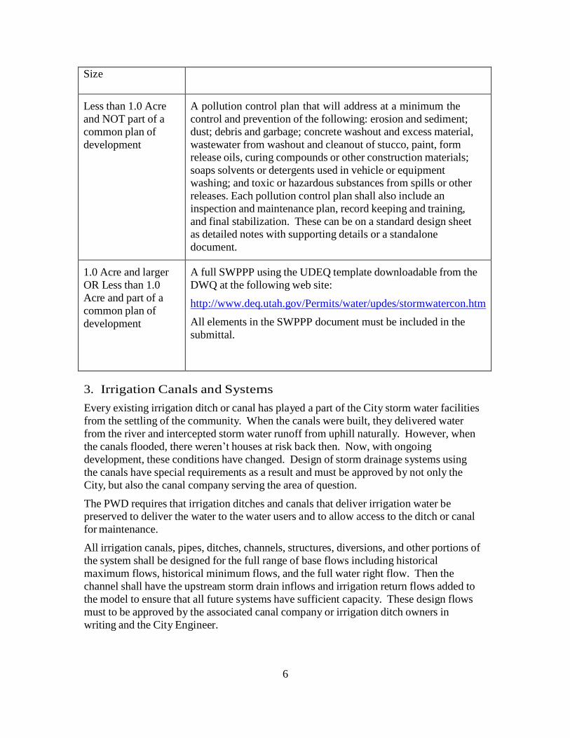
Table B-2, SWPPP Requirements
Contributing Area Minimum Requirements
6
Size
Less than 1.0 Acre
and NOT part of a
common plan of
development
A pollution control plan that will address at a minimum the
control and prevention of the following: erosion and sediment;
dust; debris and garbage; concrete washout and excess material,
wastewater from washout and cleanout of stucco, paint, form
release oils, curing compounds or other construction materials;
soaps solvents or detergents used in vehicle or equipment
washing; and toxic or hazardous substances from spills or other
releases. Each pollution control plan shall also include an
inspection and maintenance plan, record keeping and training,
and final stabilization. These can be on a standard design sheet
as detailed notes with supporting details or a standalone
document.
1.0 Acre and larger
OR Less than 1.0
Acre and part of a
common plan of
development
A full SWPPP using the UDEQ template downloadable from the
DWQ at the following web site:
http://www.deq.utah.gov/Permits/water/updes/stormwatercon.htm
All elements in the SWPPP document must be included in the
submittal.
3. Irrigation Canals and Systems
Every existing irrigation ditch or canal has played a part of the City storm water facilities
from the settling of the community. When the canals were built, they delivered water
from the river and intercepted storm water runoff from uphill naturally. However, when
the canals flooded, there weren’t houses at risk back then. Now, with ongoing
development, these conditions have changed. Design of storm drainage systems using
the canals have special requirements as a result and must be approved by not only the
City, but also the canal company serving the area of question.
The PWD requires that irrigation ditches and canals that deliver irrigation water be
preserved to deliver the water to the water users and to allow access to the ditch or canal
for maintenance.
All irrigation canals, pipes, ditches, channels, structures, diversions, and other portions of
the system shall be designed for the full range of base flows including historical
maximum flows, historical minimum flows, and the full water right flow. Then the
channel shall have the upstream storm drain inflows and irrigation return flows added to
the model to ensure that all future systems have sufficient capacity. These design flows
must to be approved by the associated canal company or irrigation ditch owners in
writing and the City Engineer.
7
a) Water Right Flows
The design flow will be the maximum flow allowed by the canal water rights. Flows
down laterals and distribution ditches shall be obtained in accordance with the
agreements between the Cities and the canal companies Obtain the water righted flows
and the lateral flows directly from the canal companies. These must be documented in a
letter signed by an authorized canal company representative to be accepted by the City.
Primary canal company contacts are available from the City.
b) Return Flows
Many of the canals receive return flows from the upstream canals. This can seriously
complicate the storm water design since many people turn off their irrigation water and
simply pass it down the ditch during storms. This can result in major flooding issues on
some canals, even without any storm water entering the canals. When designing a
section of the canal, it shall be necessary to take the return flows into consideration and to
discuss them with the canal companies. Again, the agreed upon flows must be obtained
in accordance with the canal agreements with the Cities.
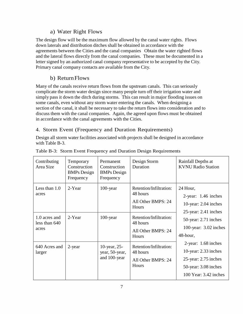
4. Storm Event (Frequency and Duration Requirements)
Design all storm water facilities associated with projects shall be designed in accordance
with Table B-3.
Table B-3: Storm Event Frequency and Duration Design Requirements
Contributing
Area Size
Temporary
Construction
BMPs Design
Frequency
Permanent
Construction
BMPs Design
Frequency
Design Storm
Duration
Rainfall Depths at
KVNU Radio Station
Less than 1.0
acres
2-Year
100-year
Retention/Infiltration:
48 hours
All Other BMPS: 24
Hours
24 Hour,
2-year: 1.46 inches
10-year: 2.04 inches
25-year: 2.41 inches
50-year: 2.71 inches
100-year: 3.02 inches
48-hour,
2-year: 1.68 inches
10-year: 2.33 inches
25-year: 2.75 inches
50-year: 3.08 inches
100 Year: 3.42 inches
1.0 acres and
less than 640
acres
2-Year
100-year
Retention/Infiltration:
48 hours
All Other BMPS: 24
Hours
640 Acres and
larger
2-year
10-year, 25-
year, 50-year,
and 100-year
Retention/Infiltration:
48 hours
All Other BMPS: 24
Hours
8
Existing development shall be required to construct storm water facilities to meet the new
storm water design criteria at the time of redevelopment or reconstruction of any
facilities. However, the return frequency and design duration may be modified under
extreme conditions at the direction of the City Engineer with approval of the agency
managing the receiving waters in writing.
5. Allowable Storm Water Discharge
There are two criteria related to the allowable discharge that shall be met by all projects.
Any exceptions to this requirement shall be evaluated and approved on a case by case
basis using the methodology provided in this document and other equivalent water
quality treatments shall be utilized. Approval by the PWD is required before any
deviations are allowed.
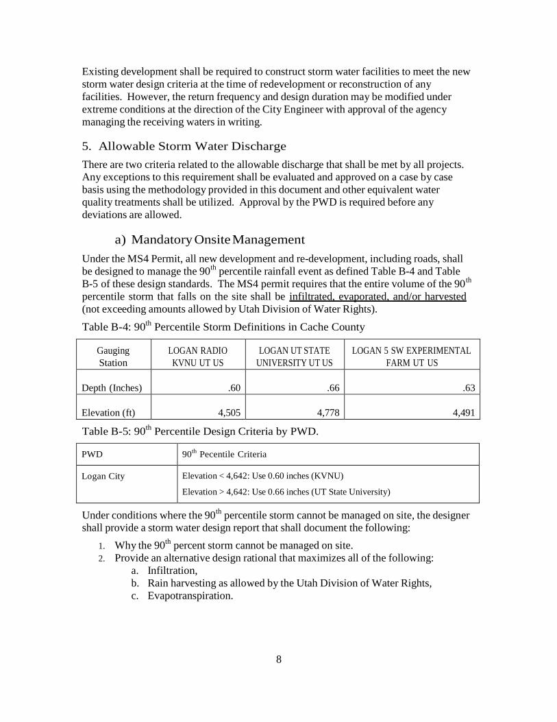
a) Mandatory Onsite Management
Under the MS4 Permit, all new development and re-development, including roads, shall
be designed to manage the 90th
percentile rainfall event as defined Table B-4 and Table
B-5 of these design standards. The MS4 permit requires that the entire volume of the 90th
percentile storm that falls on the site shall be infiltrated, evaporated, and/or harvested
(not exceeding amounts allowed by Utah Division of Water Rights).
Table B-4: 90th
Percentile Storm Definitions in Cache County
Gauging
Station
LOGAN RADIO
KVNU UT US
LOGAN UT STATE
UNIVERSITY UT US
LOGAN 5 SW EXPERIMENTAL
FARM UT US
Depth (Inches)
.60
.66
.63
Elevation (ft)
4,505
4,778
4,491
Table B-5: 90th
Percentile Design Criteria by PWD.
PWD 90th
Pecentile Criteria
Logan City
Elevation < 4,642: Use 0.60 inches (KVNU)
Elevation > 4,642: Use 0.66 inches (UT State University)
Under conditions where the 90th
percentile storm cannot be managed on site, the designer
shall provide a storm water design report that shall document the following:
1. Why the 90th
percent storm cannot be managed on site.
2. Provide an alternative design rational that maximizes all of the following:
a. Infiltration,
b. Rain harvesting as allowed by the Utah Division of Water Rights,
c. Evapotranspiration.
9
b) Maximum Allowable Discharge
Most of the storm water in Cache Valley discharges to irrigation ditches and canals
before reaching the rivers and streams. However, the ditches and canals are not designed
to carry the increase in flows and are at risk of flooding both private and public property.
Through negotiations with the canal companies, the following flow rate restrictions have
been agreed upon:
1) The storm water runoff leaving the site during the 1 percent (100-year) event shall not
exceed the lesser of:
1. Discharge prior to development (Historical Runoff Flow), or
2. 0.2 cfs per acre.
2) All storm water calculations shall include the following:
a) A calculation of Historical/Predevelopment flow rate. This is defined as the flow
rate off of an irrigated pasture in good condition using the NRCS Curve Number
Methodology defined in Section 3 of this standard.
i) If the Historical /Predevelopment flow rate is greater than 0.2 cfs/acre, then
the maximum allowable discharge is 0.2 cfs/acre.
ii) If the Historical/Predevelopment flow rate is less than 0.2 cfs/acre, then the
Historical/Predevelopment flow rate is the maximum allowable discharge.
b) A calculation of the Post-Construction flow rate and volume. If the Post-
Construction flow rate, after the removal of the 90th
percentile storm in B.4.a
above, exceeds the maximum allowable discharge, additional detention or
retention of flows shall be included in the design until the discharge is reduced to
not more than the maximum allowable discharge.
3) The locations of the storm water discharge shall not be altered without permission. This is interpreted to mean that the ditches or canals receiving the discharge cannot be
changed without express approval of the managers of the receiving ditches or canals.
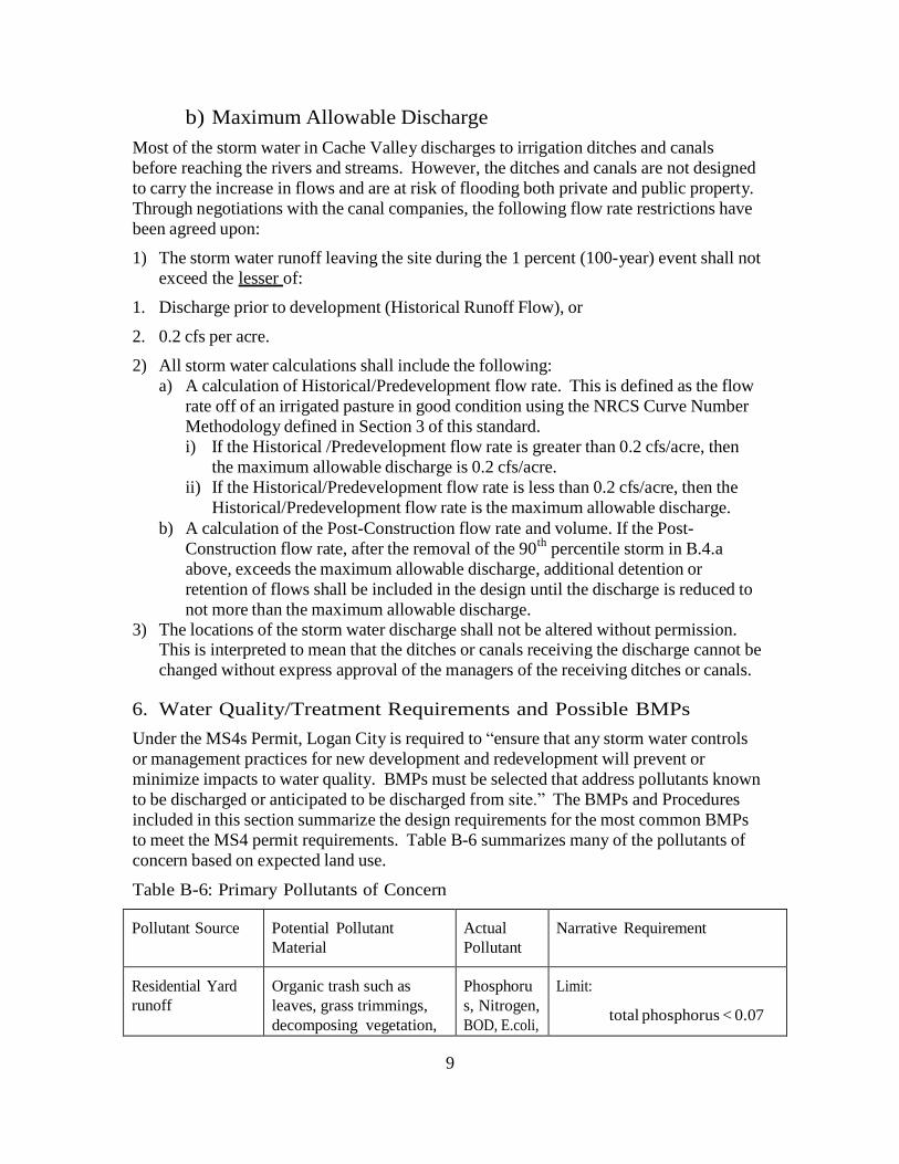
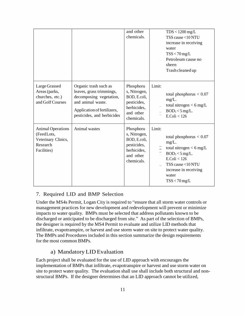
6. Water Quality/Treatment Requirements and Possible BMPs
Under the MS4s Permit, Logan City is required to “ensure that any storm water controls
or management practices for new development and redevelopment will prevent or
minimize impacts to water quality. BMPs must be selected that address pollutants known
to be discharged or anticipated to be discharged from site.” The BMPs and Procedures
included in this section summarize the design requirements for the most common BMPs
to meet the MS4 permit requirements. Table B-6 summarizes many of the pollutants of
concern based on expected land use.
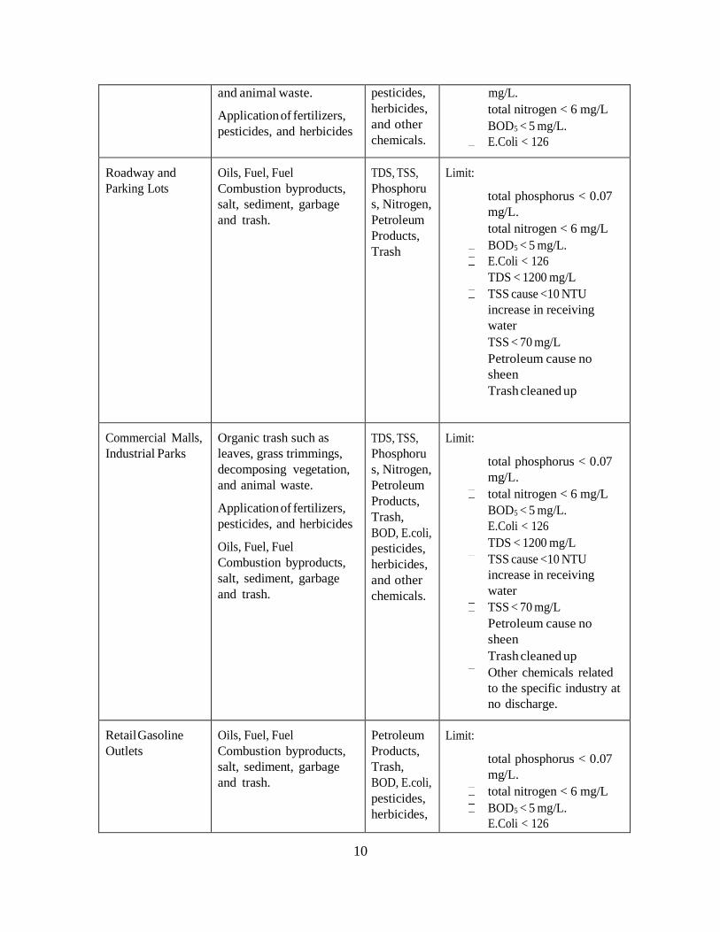
Table B-6: Primary Pollutants of Concern
Pollutant Source
Potential Pollutant
Material
Actual
Pollutant
Narrative Requirement
Residential Yard
runoff
Organic trash such as
leaves, grass trimmings,
decomposing vegetation,
Phosphoru
s, Nitrogen,
BOD, E.coli,
Limit:
total phosphorus < 0.07
10
and animal waste.
Application of fertilizers,
pesticides, and herbicides
pesticides,
herbicides,
and other
chemicals.
mg/L.
total nitrogen < 6 mg/L
BOD5 < 5 mg/L.
E.Coli < 126
Roadway and
Parking Lots
Oils, Fuel, Fuel
Combustion byproducts,
salt, sediment, garbage
and trash.
TDS, TSS,
Phosphoru
s, Nitrogen,
Petroleum
Products,
Trash
Limit:
total phosphorus < 0.07
mg/L.
total nitrogen < 6 mg/L
BOD5 < 5 mg/L.
E.Coli < 126
TDS < 1200 mg/L
TSS cause <10 NTU
increase in receiving
water
TSS < 70 mg/L
Petroleum cause no
sheen
Trash cleaned up
Commercial Malls,
Industrial Parks
Organic trash such as
leaves, grass trimmings,
decomposing vegetation,
and animal waste.
Application of fertilizers,
pesticides, and herbicides
Oils, Fuel, Fuel
Combustion byproducts,
salt, sediment, garbage
and trash.
TDS, TSS,
Phosphoru
s, Nitrogen,
Petroleum
Products,
Trash,
BOD, E.coli,
pesticides,
herbicides,
and other
chemicals.
Limit:
total phosphorus < 0.07
mg/L.
total nitrogen < 6 mg/L
BOD5 < 5 mg/L.
E.Coli < 126
TDS < 1200 mg/L
TSS cause <10 NTU
increase in receiving
water
TSS < 70 mg/L
Petroleum cause no
sheen
Trash cleaned up
Other chemicals related
to the specific industry at
no discharge.
Retail Gasoline
Outlets
Oils, Fuel, Fuel
Combustion byproducts,
salt, sediment, garbage
and trash.
Petroleum
Products,
Trash,
BOD, E.coli,
pesticides,
herbicides,
Limit:
total phosphorus < 0.07
mg/L.
total nitrogen < 6 mg/L
BOD5 < 5 mg/L.
E.Coli < 126
11
and other
chemicals.
TDS < 1200 mg/L
TSS cause <10 NTU
increase in receiving
water
TSS < 70 mg/L
Petroleum cause no
sheen
Trash cleaned up
Large Grassed
Areas (parks,
churches, etc.)
and Golf Courses
Organic trash such as
leaves, grass trimmings,
decomposing vegetation,
and animal waste.
Application of fertilizers,
pesticides, and herbicides
Phosphoru
s, Nitrogen,
BOD, E.coli,
pesticides,
herbicides,
and other
chemicals.
Limit:
total phosphorus < 0.07
mg/L.
total nitrogen < 6 mg/L
BOD5 < 5 mg/L.
E.Coli < 126
Animal Operations
(Feed Lots,
Veterinary Clinics,
Research
Facilities)
Animal wastes
Phosphoru
s, Nitrogen,
BOD, E.coli,
pesticides,
herbicides,
and other
chemicals.
Limit:
total phosphorus < 0.07
mg/L.
total nitrogen < 6 mg/L
BOD5 < 5 mg/L.
E.Coli < 126
TSS cause <10 NTU
increase in receiving
water
TSS < 70 mg/L
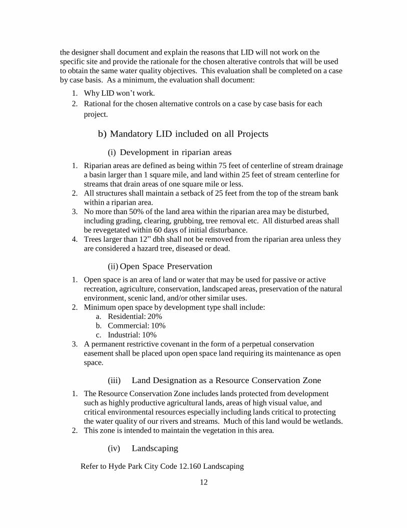
7. Required LID and BMP Selection
Under the MS4s Permit, Logan City is required to “ensure that all storm water controls or
management practices for new development and redevelopment will prevent or minimize
impacts to water quality. BMPs must be selected that address pollutants known to be
discharged or anticipated to be discharged from site.” As part of the selection of BMPs,
the designer is required by the MS4 Permit to evaluate and utilize LID methods that
infiltrate, evapotranspire, or harvest and use storm water on site to protect water quality.
The BMPs and Procedures included in this section summarize the design requirements
for the most common BMPs.
a) Mandatory LID Evaluation
Each project shall be evaluated for the use of LID approach with encourages the
implementation of BMPs that infiltrate, evapotranspire or harvest and use storm water on
site to protect water quality. The evaluation shall use shall include both structural and non-
structural BMPs. If the designer determines that an LID approach cannot be utilized,
12
the designer shall document and explain the reasons that LID will not work on the
specific site and provide the rationale for the chosen alterative controls that will be used
to obtain the same water quality objectives. This evaluation shall be completed on a case
by case basis. As a minimum, the evaluation shall document:
1. Why LID won’t work.
2. Rational for the chosen alternative controls on a case by case basis for each
project.
b) Mandatory LID included on all Projects
(i) Development in riparian areas
1. Riparian areas are defined as being within 75 feet of centerline of stream drainage
a basin larger than 1 square mile, and land within 25 feet of stream centerline for
streams that drain areas of one square mile or less.
2. All structures shall maintain a setback of 25 feet from the top of the stream bank
within a riparian area.
3. No more than 50% of the land area within the riparian area may be disturbed,
including grading, clearing, grubbing, tree removal etc. All disturbed areas shall
be revegetated within 60 days of initial disturbance.
4. Trees larger than 12” dbh shall not be removed from the riparian area unless they
are considered a hazard tree, diseased or dead.
(ii) Open Space Preservation
1. Open space is an area of land or water that may be used for passive or active
recreation, agriculture, conservation, landscaped areas, preservation of the natural
environment, scenic land, and/or other similar uses.
2. Minimum open space by development type shall include:
a. Residential: 20%
b. Commercial: 10%
c. Industrial: 10%
3. A permanent restrictive covenant in the form of a perpetual conservation
easement shall be placed upon open space land requiring its maintenance as open
space.
(iii) Land Designation as a Resource Conservation Zone
1. The Resource Conservation Zone includes lands protected from development
such as highly productive agricultural lands, areas of high visual value, and
critical environmental resources especially including lands critical to protecting
the water quality of our rivers and streams. Much of this land would be wetlands.
2. This zone is intended to maintain the vegetation in this area.
(iv) Landscaping
Refer to Hyde Park City Code 12.160 Landscaping
13
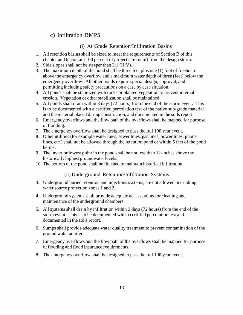
c) Infiltration BMPS
(i) At Grade Retention/Infiltration Basins
1. All retention basins shall be sized to meet the requirements of Section B of this
chapter and to contain 100 percent of project site runoff from the design storm.
2. Side slopes shall not be steeper than 3:1 (H:V).
3. The maximum depth of the pond shall be three feet plus one (1) foot of freeboard
above the emergency overflow and a maximum water depth of three (feet) below the
emergency overflow. All other ponds require special design, approval, and
permitting including safety precautions on a case by case situation.
4. All ponds shall be stabilized with rocks or planted vegetation to prevent internal
erosion. Vegetation or other stabilization shall be maintained.
5. All ponds shall drain within 3 days (72 hours) from the end of the storm event. This
is to be documented with a certified percolation test of the native sub-grade material
and the material placed during construction, and documented in the soils report.
6. Emergency overflows and the flow path of the overflows shall be mapped for purpose
of flooding.
7. The emergency overflow shall be designed to pass the full 100 year event.
8. Other utilities (for example water lines, sewer lines, gas lines, power lines, phone
lines, etc.) shall not be allowed through the retention pond or within 5 feet of the pond
berms.
9. The invert or lowest point in the pond shall be not less than 12-inches above the
historically highest groundwater levels.
10. The bottom of the pond shall be finished to maintain historical infiltration.
(ii) Underground Retention/Infiltration Systems
3. Underground buried retention and injections systems, are not allowed in drinking
water source protection zones 1 and 2.
4. Underground systems shall provide adequate access points for cleaning and
maintenance of the underground chambers.
5. All systems shall drain by infiltration within 3 days (72 hours) from the end of the
storm event. This is to be documented with a certified percolation test and
documented in the soils report.
6. Sumps shall provide adequate water quality treatment to prevent contamination of the
ground water aquifer.
7. Emergency overflows and the flow path of the overflows shall be mapped for purpose
of flooding and flood insurance requirements.
8. The emergency overflow shall be designed to pass the full 100 year event.

9. Other utilities (for example water lines, sewer lines, gas lines, power lines, phone
lines, etc.) shall not be allowed through or under the underground retention system.
10. Registration with the DWQ and a Class 5 Injection Well Permit are required for all
underground retention/infiltration systems.
(iii) Infiltration Trenches
1. Infiltration trenches are not allowed in drinking water source protection zones 1 and
2.
2. Infiltration trenches shall provide adequate access points for cleaning and
maintenance underground piping.
3. Infiltration trenches shall drain by infiltration within 3 days (72 hours) from the end
of the storm event to provide adequate storage for a subsequent event. This is to be
documented with a certified percolation test and documented in the soils report.
4. Infiltration trenches shall have adequate water quality treatment to prevent
contamination of the ground water aquifer.
5. Emergency overflows and the flow path of the overflows shall be mapped for purpose
of flooding and flood insurance requirements.
6. The emergency overflow shall be designed to pass the full 100 year event.
7. Other utilities (for example water lines, sewer lines, gas lines, power lines, phone
lines, etc.) shall not be allowed through or under the infiltration trenches.
8. Registration with the DWQ and a Class 5 Injection Well Permit are required for all
infiltration trenches.
(iv) Infiltration Swales
1. Side slopes shall not be steeper than 4:1 (H:V).
2. The maximum depth of the pond shall be one (1) foot.
3. All ponds shall be landscaped per landscaping requirements. Vegetation or other
stabilization shall be maintained.
4. All swales shall drain within 3 days (72 hours) from the end of the storm event. This
is to be documented with a certified percolation test of the native sub-grade material
and the material placed during construction, and documented in the soils report.
5. Emergency overflows and the flow path of the overflows shall be mapped for purpose
of flooding to ensure all emergency overflows are to the PWD drainage system
6. The invert or lowest point in the pond shall be not less than 12-inches above the
historically highest groundwater levels.
7. The bottom of the pond shall be finished to maintain historical infiltration.
(v) Permeable Pavements
Permeable (or pervious) pavements contain small voids that allow water to pass through
to a stone base. They come in a variety of forms; they may be modular paving system
(concrete pavers, modular grass or gravel grids) or poured0in0place pavement (porous
15
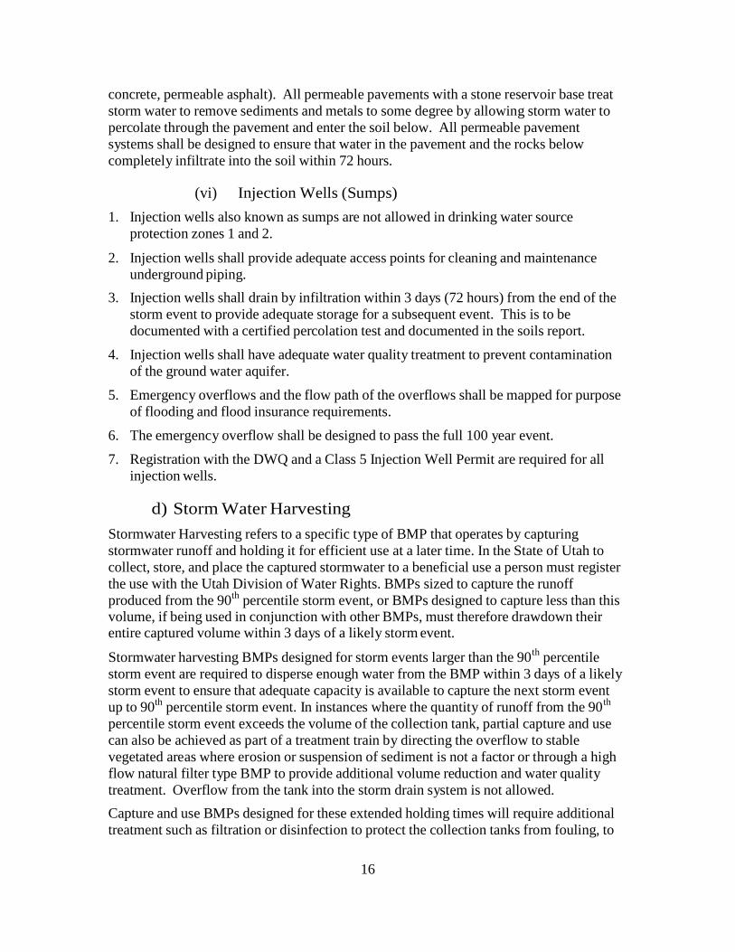
concrete, permeable asphalt). All permeable pavements with a stone reservoir base treat
storm water to remove sediments and metals to some degree by allowing storm water to
percolate through the pavement and enter the soil below. All permeable pavement
systems shall be designed to ensure that water in the pavement and the rocks below
completely infiltrate into the soil within 72 hours.
(vi) Injection Wells (Sumps)
1. Injection wells also known as sumps are not allowed in drinking water source
protection zones 1 and 2.
2. Injection wells shall provide adequate access points for cleaning and maintenance
underground piping.
3. Injection wells shall drain by infiltration within 3 days (72 hours) from the end of the
storm event to provide adequate storage for a subsequent event. This is to be
documented with a certified percolation test and documented in the soils report.
4. Injection wells shall have adequate water quality treatment to prevent contamination
of the ground water aquifer.
5. Emergency overflows and the flow path of the overflows shall be mapped for purpose
of flooding and flood insurance requirements.
6. The emergency overflow shall be designed to pass the full 100 year event.
7. Registration with the DWQ and a Class 5 Injection Well Permit are required for all
injection wells.
d) Storm Water Harvesting
Stormwater Harvesting refers to a specific type of BMP that operates by capturing
stormwater runoff and holding it for efficient use at a later time. In the State of Utah to
collect, store, and place the captured stormwater to a beneficial use a person must register
the use with the Utah Division of Water Rights. BMPs sized to capture the runoff
produced from the 90th
percentile storm event, or BMPs designed to capture less than this volume, if being used in conjunction with other BMPs, must therefore drawdown their entire captured volume within 3 days of a likely storm event.
Stormwater harvesting BMPs designed for storm events larger than the 90th
percentile
storm event are required to disperse enough water from the BMP within 3 days of a likely
storm event to ensure that adequate capacity is available to capture the next storm event
up to 90th
percentile storm event. In instances where the quantity of runoff from the 90th
percentile storm event exceeds the volume of the collection tank, partial capture and use
can also be achieved as part of a treatment train by directing the overflow to stable
vegetated areas where erosion or suspension of sediment is not a factor or through a high
flow natural filter type BMP to provide additional volume reduction and water quality
treatment. Overflow from the tank into the storm drain system is not allowed.
Capture and use BMPs designed for these extended holding times will require additional
treatment such as filtration or disinfection to protect the collection tanks from fouling, to
16
17
prevent the breeding of vectors, and/or to improve the quality of water for reuse
applications. These scenarios will be reviewed on a case-by-case basis.
e) Natural Filters
Natural Filter facilities are landscaped shallow depressions that capture and filter
stormwater runoff. As stormwater passes down through the planting soil, pollutants are
filtered, adsorbed, and biodegraded by the soil and plants. Because they are not contained
within an impermeable structure, they may allow for infiltration.
Projects that have demonstrated they cannot manage 100% of the water quality design
volume onsite through infiltration and/or stormwater harvesting BMPs may manage the
remaining volume through the use of a high removal efficiency natural filter BMP. A
high removal efficiency natural filter BMP shall be sized to adequately capture 1.5 times
the volume not managed through infiltration and/or capture and use.
(i) Bio-Filters
Most natural filter systems can be classified as biofilters. They normally consist of a
ponding area, mulch layer, planting soils, plants, and in some cases an underdrain. Runoff
that passes through a biofiltration system is treated by the natural absorption and filtration
characteristics of the plants, soils, and microbes with which the water contacts.
(ii) Rain Gardens
Rain gardens are simply gardens designed to capture and treat runoff. They are generally
small in size and should not be used to treat impervious areas exceeding 4,000 square
feet. Rain gardens most often utilize native plant species and soil amendments to
encourage absorption of stormwater. For projects with impervious areas exceeding 4,000
square feet biofilters, planter boxes with infiltration, vegetated swales or natural buffer
strips should be considered.
(iii) Planter Boxes with infiltration
Planter boxes with infiltration are natural filtration treatment control measures located in
and around structures and facilities to handle larger volumes of water than a typical rain
garden. They typically are constructed with vertical or near vertical sides and above
ground. They can be equipped with underdrains if necessary. Planter boxes with
infiltration should maintain setbacks from adjacent buildings, other structures, sidewalks
or roadways.
(iv) Vegetated Swales
Vegetated swales are open, shallow channels with dense, low‐lying vegetation covering
the side slopes and bottom that collect and slowly convey runoff to downstream
discharge points. An effective vegetated swale achieves uniform sheet flow through the densely vegetated area for a period of several minutes. The vegetation in the swale can
vary depending on its location and is the choice of the designer. Most swales are
grass‐lined.
18
(v) Filter or Buffer Strips
Filter strips are vegetated areas designed to treat sheet flow runoff from adjacent
impervious surfaces such as parking lots and roadways, or intensive landscaped areas such as golf courses. While some assimilation of dissolved constituents may occur, filter
strips are generally more effective in trapping sediment and particulate‐bound metals,
nutrients, and pesticides. Filter strips are more effective when the runoff passes through
the vegetation and thatch layer in the form of shallow, uniform flow. Filter strips are primarily used to pretreat runoff before it flows to an infiltration BMP or another natural
filtration BMP.
f) Man-Made Treatment
(i) Planter Boxes
Planter boxes are bioretention treatment control measures that are completely contained
within an impermeable structure with an underdrain (they do not infiltrate). They are
similar to bioretention facilities with underdrains except they are situated at or above
ground and are bound by impermeable walls. Planter boxes may be placed adjacent to or
near buildings, other structures, or sidewalks.
(ii) Hydrodynamic Seperators
Hydrodynamic separators are stormwater management devices that work primarily based
on vortex and gravity principles to separate stormwater from the pollutants. They are
generally designed as flow-through systems with either on-line or off-line storage of
pollutants. They include chambers for settling and storage of pollutants and are often
used in conjunction with other BMPs as pretreatment. They are not especially effective
for the removal of fine materials or dissolved pollutants. On-line separators are more
susceptible to scour or re-suspension of pollutants than systems that incorporate off-line
storage.
g) Settlement systems
Settlement systems are used to store and settle out sediment using Stokes Law. This
approach does not infiltrate, harvest, or evaporate sufficient water. However, it can be
used in combination with other BMPs to ensure treatment of water above the 90th
percentile storm to ensure water quality requirements and the flow requirements of the
canal companies are met.
(i) At Grade Detention Basins
1. Side slopes shall not be steeper than 3:1 (H:V).
2. The maximum depth at the emergency overflow location of the pond shall be
three feet plus one (1) foot of freeboard above the emergency overflow and a
maximum water depth of three (feet) below the emergency overflow. All other
ponds require special design, approval, and permitting including safety
precautions on a case by case situation.

19
3. All ponds shall be stabilized with rocks or planted vegetation to prevent internal
erosion. Vegetation or other stabilization must be maintained.
4. Where orifice and snouts are used, the orifice size is limited to not less than three
(3) inches in diameter to prevent clogging.
5. Emergency overflows and the flow path of the overflows shall be mapped to
natural streams, canals, or city approved drainage system for purpose of flood
mapping using existing topographic mapping.
6. The emergency overflow shall be designed to pass the full 100 year event.
7. Other utilities (for example water lines, sewer lines, gas lines, power lines, phone
lines, etc.) shall not be allowed through the detention pond or within 5 feet of the
pond berms.
8. The invert or lowest point in the pond shall be not less than 12-inches above the
historically highest groundwater levels (whichever is higher).
9. The bottom of the pond shall be finished to maintain historical infiltration.
(ii) Underground Detention Systems
1. Underground systems shall provide adequate access points for cleaning and
maintenance.
2. All Detention systems shall drain by discharge (detention basins) within 3 days
(72 hours) from the end of the storm event. This is to be documented.
3. Emergency overflows and the flow path of the overflows shall be mapped for
purpose of flooding and flood insurance requirements.
4. The emergency overflow shall be designed to pass the full 100 year event.
5. Other utilities (for example water lines, sewer lines, gas lines, power lines, phone
lines, etc.) shall not be allowed through or under the underground retention
system. 8. Curb and Gutter Flow Design
1. The flow depth in the gutter shall not be allowed to exceed the lesser of the top back
of curb elevation (TBC) or the peak drive way approach elevation during the required
storm event. This includes a combination of piping, curb and gutter, and ditches.
2. Where the flow depth is exceeded, storm drain inlets and a piped system shall be
required and appropriate actions taken to eliminate overtopping of the curbs and
flooding private property. 9. Channel Design
1. Channel side slopes shall not be steeper than 3:1 (H:V) unless they are concrete.
Where they are incorporated into landscaping, flatter slopes shall be required. This
will be evaluated on a case by case basis.

20
2. Channel velocities shall be slow enough to prevent scour, and where possible,
facilitate further settlement of sediments unless the channel is used to deliver
irrigation water as well. If the channel will also carry irrigation water, maintain
velocities above 2 ft/sec if possible, but at no time exceed 4 ft/sec.
3. Where rip-rap is used, design shall be in accordance with EM-1110 from the US
Army Corp of Engineers or HEC-11 from the Federal Highway Administration.
4. Free board on the channels shall be in compliance with the Bureau of Reclamation,
Design of Small Canal Structures.
5. Channel maintenance easements shall be maintained as required in the City and Canal
Company agreements.
10. Pipe Design
1. For storm water pipes, roughness coefficients listed in the table included in Section D
of these standards that coincide with the accepted pipe materials in the City’s
Standard Specifications, most current edition shall be used.
2. Maintain velocities in the pipes at design flows sufficient to prevent sediment
deposition and low enough to prevent scour damage to the pipe.
3. Pipe outlets shall have a flared end discharge unless more stringent methods of
energy dissipation are required.
4. Minimum diameter of storm drains shall be:
5. 12 inches for laterals
6. 15 inches for trunk lines
7. 18 inches under the UDOT right of way.
8. Pipe sizes shall not decrease in the downstream direction.
9. Maximum flow depth in the pipe during the design storm shall not exceed 0.85 times
the diameter of the pipe.
C. REQUIRED HYDROLOGIC METHODOLOGY
1. Design Methodology
Table C-1 summarizes the required methods based on the area contributing flows to the
system, including offsite flows. THE RATIONAL EQUATION IS NOT ALLOWED
FOR DESIGN OF BEST MANAGEMENT PRACTICES.
Table C-1, Hydrologic Methods Required
Contributing Area (Acres)
Methodology Required
Less than 10.0 Acre
SCS Method with calculated time of concentration. Time
of Concentration shall not be less than 5 minutes.
21
Greater than 10.0 Acres SCS Method. The time of concentration can be
calculated or hydrodynamic solutions may be used. If
hydrodynamic solutions are used, the model must be
provided to the PWD for detailed review of all
assumptions and data used.
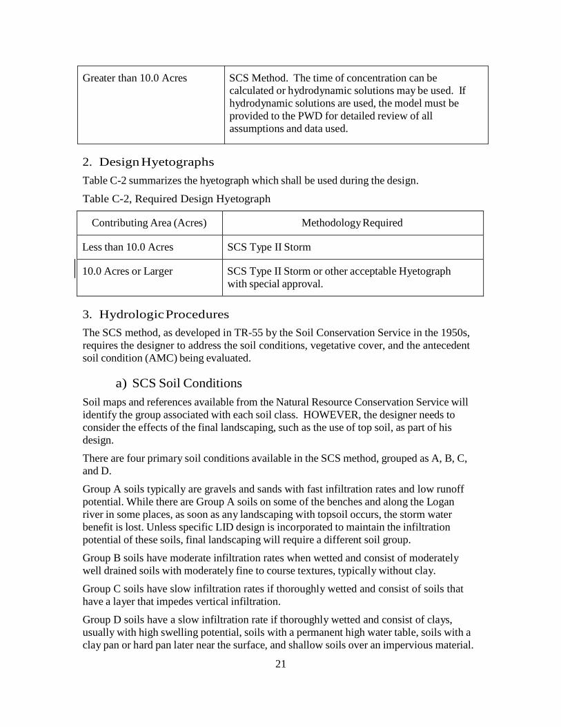
2. Design Hyetographs
Table C-2 summarizes the hyetograph which shall be used during the design.
Table C-2, Required Design Hyetograph
Contributing Area (Acres)
Methodology Required
Less than 10.0 Acres
SCS Type II Storm
10.0 Acres or Larger
SCS Type II Storm or other acceptable Hyetograph
with special approval.
3. Hydrologic Procedures
The SCS method, as developed in TR-55 by the Soil Conservation Service in the 1950s,
requires the designer to address the soil conditions, vegetative cover, and the antecedent
soil condition (AMC) being evaluated.
a) SCS Soil Conditions
Soil maps and references available from the Natural Resource Conservation Service will
identify the group associated with each soil class. HOWEVER, the designer needs to
consider the effects of the final landscaping, such as the use of top soil, as part of his
design.
There are four primary soil conditions available in the SCS method, grouped as A, B, C,
and D.
Group A soils typically are gravels and sands with fast infiltration rates and low runoff
potential. While there are Group A soils on some of the benches and along the Logan
river in some places, as soon as any landscaping with topsoil occurs, the storm water
benefit is lost. Unless specific LID design is incorporated to maintain the infiltration
potential of these soils, final landscaping will require a different soil group.
Group B soils have moderate infiltration rates when wetted and consist of moderately
well drained soils with moderately fine to course textures, typically without clay.
Group C soils have slow infiltration rates if thoroughly wetted and consist of soils that
have a layer that impedes vertical infiltration.
Group D soils have a slow infiltration rate if thoroughly wetted and consist of clays,
usually with high swelling potential, soils with a permanent high water table, soils with a
clay pan or hard pan later near the surface, and shallow soils over an impervious material.
22
b) Antecedent Soil Conditions
In addition to the soil group, the antecedent moisture condition (AMC) must also be
considered. For the average case, the SCS has defined AMC II to apply as the definition
of the conditions preceding most annual floods. For this purpose, AMC II will be used
for all PWD approved projects.
Upon selecting the soil group, the appropriate curve number can be selected from various
standard references and text books. A common free reference is the HEC-HMS technical
reference manual which can be downloaded from the Army Corp of Engineers HEC
website. Runoff coefficients are subject to approval by the City Engineer.
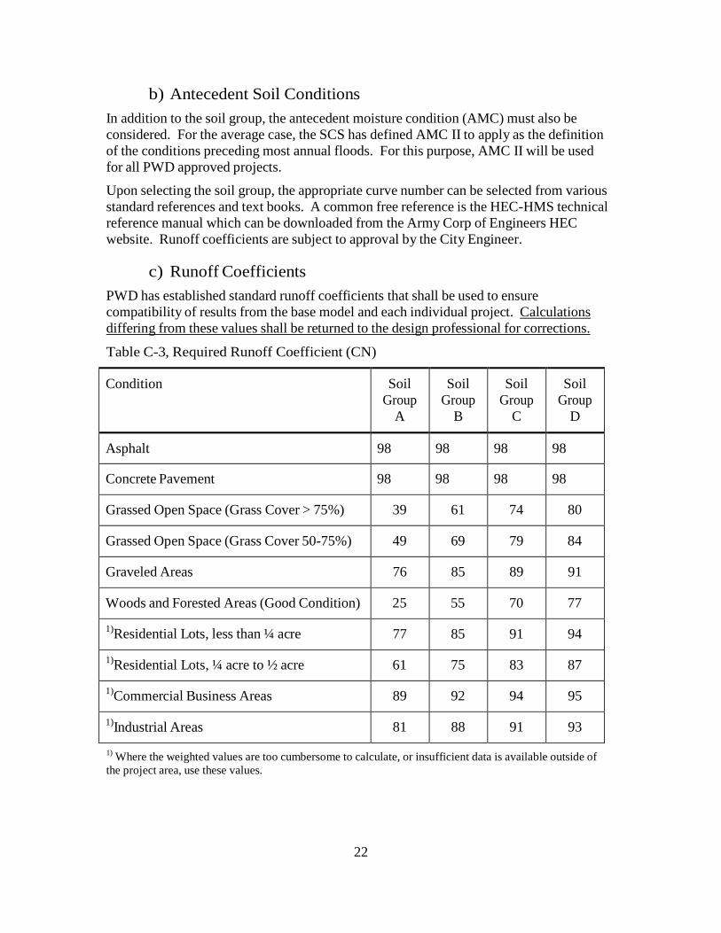
c) Runoff Coefficients
PWD has established standard runoff coefficients that shall be used to ensure
compatibility of results from the base model and each individual project. Calculations
differing from these values shall be returned to the design professional for corrections.
Table C-3, Required Runoff Coefficient (CN)
Condition
Soil
Group
A
Soil
Group
B
Soil
Group
C
Soil
Group
D
Asphalt
98
98
98
98
Concrete Pavement
98
98
98
98
Grassed Open Space (Grass Cover > 75%)
39
61
74
80
Grassed Open Space (Grass Cover 50-75%)
49
69
79
84
Graveled Areas
76
85
89
91
Woods and Forested Areas (Good Condition)
25
55
70
77
1)Residential Lots, less than ¼ acre
77
85
91
94
1)Residential Lots, ¼ acre to ½ acre
61
75
83
87
1)Commercial Business Areas
89
92
94
95
1)Industrial Areas
81
88
91
93
1) Where the weighted values are too cumbersome to calculate, or insufficient data is available outside of
the project area, use these values.
23
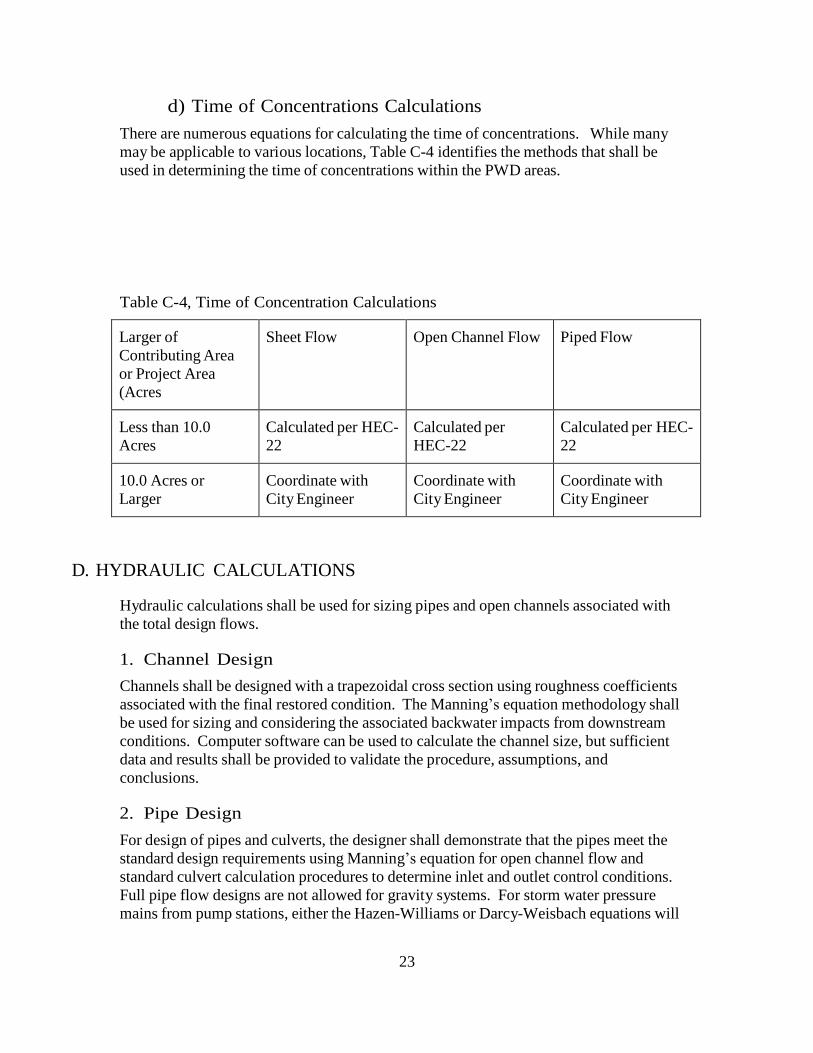
d) Time of Concentrations Calculations
There are numerous equations for calculating the time of concentrations. While many
may be applicable to various locations, Table C-4 identifies the methods that shall be
used in determining the time of concentrations within the PWD areas.
Table C-4, Time of Concentration Calculations
Larger of
Contributing Area
or Project Area
(Acres
Sheet Flow
Open Channel Flow
Piped Flow
Less than 10.0
Acres
Calculated per HEC-
22
Calculated per
HEC-22
Calculated per HEC-
22
10.0 Acres or
Larger
Coordinate with
City Engineer
Coordinate with
City Engineer
Coordinate with
City Engineer
D. HYDRAULIC CALCULATIONS
Hydraulic calculations shall be used for sizing pipes and open channels associated with
the total design flows.
1. Channel Design
Channels shall be designed with a trapezoidal cross section using roughness coefficients
associated with the final restored condition. The Manning’s equation methodology shall
be used for sizing and considering the associated backwater impacts from downstream
conditions. Computer software can be used to calculate the channel size, but sufficient
data and results shall be provided to validate the procedure, assumptions, and
conclusions.
2. Pipe Design
For design of pipes and culverts, the designer shall demonstrate that the pipes meet the
standard design requirements using Manning’s equation for open channel flow and
standard culvert calculation procedures to determine inlet and outlet control conditions.
Full pipe flow designs are not allowed for gravity systems. For storm water pressure
mains from pump stations, either the Hazen-Williams or Darcy-Weisbach equations will

24
be allowed. Roughness coefficients and assumptions shall be in accordance with Table
D-1 selected from various references.
Table D-1, Mannings Coefficients for Pipe
Material
Roughness “n”
Smooth Interior HDPE or ADS Pipe
.010
Corrugated Metal Pipe (CMP)
.024
Concrete
.013
PVC
.010
The design and sizing may be done manually or with the use of computer software.
However the results must be provided as part of the submittal review process.
3. Spread Width Calculations
Spread width calculations and depth of flow in the gutters shall be completed in
accordance with HEC-22 methodology developed by the Federal Highway
Administration (FHWA). These calculations can be completed using numerous available
software or manually. However, the calculations must be documented and provided to
the City for review for the design storms.


