Combustion and Flame 141 (2005) 40–54 www.elsevier.com/locate/combustflame Studies of mean and unsteady flow in a swirled combustor using experiments, acoustic analysis, and large eddy simulations S. Roux a,∗ , G. Lartigue a , T. Poinsot a,b , U. Meier c , C. Bérat d a CERFACS, 31057 Toulouse, France b IMFT, 31400 Toulouse, France c DLR, D-70569 Stuttgart, Germany d Turbomeca, 64511 Bordes, France Received 14 June 2004; received in revised form 20 September 2004; accepted 22 December 2004 Abstract The turbulent flow within a complex swirled combustor is studied with compressible large eddy simulation (LES), acoustic analysis, and experiments for both cold and reacting flows. Detailed fields of axial, tangential, and radial velocities (average and RMS) given by LES are compared with experimental values measured by LDV. The unsteady activity is identified using LES and acoustic tools for the whole geometry from inlet (far upstream of the swirler) to the atmosphere (far downstream of the chamber exhaust). Concerning comparisons between experiments and LES, this nose-to-tail procedure removes all ambiguities related to the effects of boundary con- ditions. Results for the cold flow show that the second acoustic mode at 360 Hz dominates in the plenum while a hydrodynamic mode at 540 Hz due to a precessing vortex core (PVC) is found in the combustion chamber. With combustion, the PVC mode is damped and the main mode frequency dominating all unsteady activity is 500 Hz. Acoustic analysis shows that this mode is still the second acoustic mode observed in the cold flow: its frequency shifts from 360 to 500 Hz when combustion is activated. More generally, these results illustrate the power of combined numerical tools (LES and acoustic analysis) to predict mean flow as well as instabilities in combustors. 2005 The Combustion Institute. Published by Elsevier Inc. All rights reserved. Keywords: Gas turbines; Acoustics; Large eddy simulation 1. Introduction The design of modern combustion chambers for gas turbines relies heavily on Reynolds-averaged Navier–Stokes (RANS), which predicts the mean val- ues of all parameters in the chamber (velocity, temper- * Corresponding author. E-mail address: [email protected](S. Roux). ature, density, species mass fractions, and turbulent quantities). Even though these mean fields are essen- tial ingredients of a successful design, recent research has shown that they had to be complemented by other tools. In the continuous development of gas turbines burners and chambers, unexpected problems such as flashback, quenching, or combustion oscillations ap- pear in many cases. Combustion instabilities are one of the most dangerous phenomena: these oscillations are caused by combustion/acoustics coupling and can 0010-2180/$ – see front matter 2005 The Combustion Institute. Published by Elsevier Inc. All rights reserved. doi:10.1016/j.combustflame.2004.12.007
Transcript
e
stor
lationgential,by LDV.streambetweenary con-while a
er. With500 Hz.quencywer of
bustors.
Combustion and Flame 141 (2005) 40–54www.elsevier.com/locate/combustflam
Studies of mean and unsteady flow in a swirled combuusing experiments, acoustic analysis, and
large eddy simulations
S. Rouxa,∗, G. Lartiguea, T. Poinsota,b, U. Meierc, C. Bératd
a CERFACS, 31057 Toulouse, Franceb IMFT, 31400 Toulouse, France
c DLR, D-70569 Stuttgart, Germanyd Turbomeca, 64511 Bordes, France
Received 14 June 2004; received in revised form 20 September 2004; accepted 22 December 2004
Abstract
The turbulent flow within a complex swirled combustor is studied with compressible large eddy simu(LES), acoustic analysis, and experiments for both cold and reacting flows. Detailed fields of axial, tanand radial velocities (average and RMS) given by LES are compared with experimental values measuredThe unsteady activity is identified using LES and acoustic tools for the whole geometry from inlet (far upof the swirler) to the atmosphere (far downstream of the chamber exhaust). Concerning comparisonsexperiments and LES, this nose-to-tail procedure removes all ambiguities related to the effects of boundditions. Results for the cold flow show that the second acoustic mode at 360 Hz dominates in the plenumhydrodynamic mode at 540 Hz due to a precessing vortex core (PVC) is found in the combustion chambcombustion, the PVC mode is damped and the main mode frequency dominating all unsteady activity isAcoustic analysis shows that this mode is still the second acoustic mode observed in the cold flow: its freshifts from 360 to 500 Hz when combustion is activated. More generally, these results illustrate the pocombined numerical tools (LES and acoustic analysis) to predict mean flow as well as instabilities in com 2005 The Combustion Institute. Published by Elsevier Inc. All rights reserved.
Keywords:Gas turbines; Acoustics; Large eddy simulation
forgedal-er-
lentsen-archthernesh asap-oneionscan
1. Introduction
The design of modern combustion chambersgas turbines relies heavily on Reynolds-averaNavier–Stokes (RANS), which predicts the mean vues of all parameters in the chamber (velocity, temp
0010-2180/$ – see front matter 2005 The Combustion Institutdoi:10.1016/j.combustflame.2004.12.007
ature, density, species mass fractions, and turbuquantities). Even though these mean fields are estial ingredients of a successful design, recent resehas shown that they had to be complemented by otools. In the continuous development of gas turbiburners and chambers, unexpected problems sucflashback, quenching, or combustion oscillationspear in many cases. Combustion instabilities areof the most dangerous phenomena: these oscillatare caused by combustion/acoustics coupling and
e. Published by Elsevier Inc. All rights reserved.
S. Roux et al. / Combustion and Flame 141 (2005) 40–54 41
toreldictare
ona
sticthsedde-
esee to
Sm-re-ofen
an
me/owly-sed
me-hetionseper
ESouso de-ndforndsivepo-nts
un-n aperi-iesor-inct-ESntal
ea-
f ag asisam
theolefararyats aili-
rstndaree at
msec-eaust
atre is
bi-ri-the
m-eri-
l asrepo-othto
and
er.
lead to the complete destruction of the combus[1–7]. They are difficult to predict at the design levusing RANS methods. To understand and precombustion instabilities, other numerical methodsneeded[8,9]:
• Acoustic analysis: using drastic assumptionsthe flow and on combustion, the stability ofcombustor can be studied using purely acoutools which predict the frequency and the growrates of all modes. Such tools have been uin research centers but also in industry totermine longitudinal low-frequency modes[4,10,11], longitudinal/azimuthal modes[12,13], fullythree-dimensional acoustic modes[12,14], linearor nonlinear dynamics[15–17]with analytical ornumerical techniques. The weakest part of thmodels is the description of the flame responsacoustic perturbations.
• LES: more recently, the development of LEhas allowed detailed studies of turbulent cobustion. Even though the cost of such LESmains very high, the predictive capacitiesthese tools for turbulent combustion have beclearly demonstrated[18–21]. Extending LESto study flame/acoustics coupling is thereforeobvious research path[9,22].
Although they can address the same issue (flaacoustics coupling), acoustic tools and LES folldifferent routes: while LES provides a detailed anasis of one reacting case, acoustic tools can be uto explore a wide range of parameters and geotries. Combining these solvers is likely to offer tbest solution to understand and control combusoscillations but very few studies have tried to uboth approaches together. The objective of this pais to explore this path by using simultaneously Land acoustic analysis for a swirled premixed gasecombustor. These two approaches are compared ttailed measurements performed at DLR Berlin aStuttgart. First, mean LES profiles are comparedall velocity components (mean and RMS) for cold areacting flows: this set of data constitutes an extenvalidation data base for LES results since it incorrates profiles of mean and RMS velocity componein the axial, tangential, and radial directions. Thesteady activity in the combustor is characterized isecond step using LES, acoustic analysis, and exmental results: the natural hydrodynamic instabilitof the swirled flow (especially the precessing vtex core[23]) are identified and their importanceflow/acoustics coupling is studied for cold and reaing cases. Oscillation frequencies revealed by Land acoustic analysis are compared to experime
measurements using microphones and hot-wire msurements.
An important aspect of the study is the design ocombustor and the use of numerical tools allowin‘stand-alone’ computation. LES and acoustic analyare run from an upstream section to the downstreend. Boundary conditions are extremely simple:mass-flow rate is imposed at the inlet of the whdevice while the pressure at infinity is specifiedaway from the exhaust for the outlet. No boundcondition (like velocity, species, or swirl profilesthe inlet) can be tuned to match results: this allowmore direct evaluation of the two methods’ capabties and limitations.
The experimental configuration is described fibefore providing short descriptions of the LES aacoustic tools. Results for the nonreacting flowthen presented before results for the reacting casequivalence ratio 0.75.
2. Configuration: Swirled premixed burner
The burner features a swirled injector (Fig. 1):swirl is produced by tangential injection downstreaof a plenum. The chamber has a square crosstion (86× 86 mm2) to allow optical diagnostics. Thchamber length is 110 mm and ends into an exhduct with a 6:1 contraction. The burner operatesatmospheric pressure and the inlet air temperatu300 K.
In addition to swirl, a central hub is used to stalize the flame and control its position. In the expement, methane is injected through holes located inswirler but mixing is fast so that for the present coputations, perfect premixing can be assumed. Expments include LDV velocity measurements as wela study of combustion regimes. Velocity profiles ameasured for the axial, tangential, and radial comnents at various sections of the combustor for bcold and reacting flows. Microphones are usedcharacterize the unsteady activity in the plenumin the chamber.
Fig. 1. Global view of the burner and combustion chamb
42 S. Roux et al. / Combustion and Flame 141 (2005) 40–54
n-void
eenr atheos-Sn-butup-ionsam-am
m-e isdi-
re-on-tlettheThisavesrop-ifynotnal
of-
leun-ral
allibedn
lve-
nin-helyck
entidesola-tr-
by
tion
c-mctnar
sions
Fig. 2. Boundary conditions: the atmospheric region dowstream of the exhaust (Section 3) is also meshed to aspecifying boundary conditions in this section.
To provide a nonambiguous comparison betwLES and experiments, it is important to considestand-alone configuration, i.e., a situation whereinfluence of boundary conditions is as small as psible: for example, the possibility of tuning the LEinlet or outlet conditions to match the experimetal results (a procedure which is often employedrarely mentioned for obvious reasons) must be spressed. For the present study, boundary conditwere pushed as far away as possible from the chber by extending the computational domain upstreand downstream of the combustion zone (Fig. 2): theswirlers and the plenum are fully meshed and coputed and even a part of the outside atmosphermeshed to avoid having to specify a boundary contion at the chamber exhaust (Section 3 inFig. 2). Atthe inlet of the plenum (Section 1), a flat 27 m s−1
velocity profile is imposed (Re∼ 45,000) and it waschecked that this profile had no influence on thesults as long as the total mass-flow rate was cserved. The inlet temperature is 300 K. At the ouof the combustion chamber (Section 3), a part ofexhaust atmosphere is added to the computation.is an expensive but necessary step: acoustic wreaching the chamber exhaust (Section 3) are perly transmitted or reflected without having to specan acoustic impedance for this section since it isa boundary condition but a part of the computatiodomain.
3. Large eddy simulations for gas turbines
LES are powerful tools to study the dynamicsturbulent flames[9,20,21,24–27]. In the present article a parallel LES solver called AVBP (seewww.
cerfacs.fr/cfd/) is used to solve the full compressibNavier Stokes equations on hybrid (structured andstructured) grids with third-order spatial and tempoaccuracy[28,29].
No-slip adiabatic conditions are imposed atwalls of the chamber. Subgrid stresses are descrby the WALE model[30]. Even though this model capredict wall turbulence as shown in[30], the meshsize near walls is not sufficient to correctly resoturbulent boundary layers for all walls of the combustors. This obvious limitation is well known whedealing with LES in combustion chambers but,terestingly, it has limited effects on the results. Tcomparisons of LES and LDV data show that ona limited zone near the walls is affected by the laof resolution in these regions: most of the turbulactivity is generated by the velocity gradients insthe chamber which are well resolved on the gridthat this approximation is acceptable. Other simutions performed with law-of-the-walls for LES (noshown in this paper) do not exhibit significant diffeences with the present no-slip condition.
The flame/turbulence interaction is modeledthe thickened flame/efficiency function model[22,31].The chemical scheme for methane/air combustakes into account six species (CH4, O2, CO2, CO,H2O, and N2) and two reactions[21].
(1)CH4 + 3
2O2 → CO+ 2H2O,
(2)CO+ 1
2O2 � CO2.
The first reaction(1) is irreversible whereas the seond one(2) is reversible and leads to an equilibriubetween CO and CO2 in the burnt gases and a correprediction of product temperatures as well as lamiflame speed[21]. The rates of reaction(1) and (2)arerespectively given by
(3)
q1 = A1
(ρYCH4
WCH4
)n1F(
ρYO2
WO2
)n1O
exp
(−Ea1
RT
),
q2 = A2
[(ρYCO
WCO
)n2CO(
ρYO2
WO2
)n2O
(4)−(
ρYCO2
WCO2
)n2CO2]
exp
(−Ea2
RT
),
where the parameters appearing in these expresare gathered inTable 1.
Table 1Rate constants for methane/air two-step scheme
A1 n1F n1O Ea1 A2 n2CO n2O n2CO2 Ea2
2× 10¹⁵ 0.9 1.1 35,000 2× 10⁹ 1 0.5 1 12,000
Note. The activation energies are in cal/mol and the preexponential constants in cgs units.
S. Roux et al. / Combustion and Flame 141 (2005) 40–54 43
on-Pelyin-ne-a-ting
-thet
ullyap-cifyes
rre-
cyyimeoneSn:
ndainingscens)d atticsaryies.i-ndout, a
er-
ed
ictby
ar-
a-os-
zethe
ut-(the
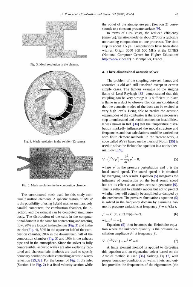
Fig. 3. Mesh resolution in the plenum.
Fig. 4. Mesh resolution in the swirler (12 vanes).
Fig. 5. Mesh resolution in the combustion chamber.
The unstructured mesh used for this study ctains 3 million elements. A specific feature of AVBis the possibility of using hybrid meshes on massivparallel computers: the combustion chamber, thejection, and the exhaust can be computed simultaously. The distribution of the cells in the computtional domain is the same for nonreacting and reacflow: 20% are located in the plenum (Fig. 3) and in theswirler (Fig. 4), 50% in the upstream half of the combustion chamber, 20% in the downstream half ofcombustion chamber (Fig. 5) and 10% in the exhauspipe and in the atmosphere. Since the solver is fcompressible, acoustic waves are also explicitly ctured and characteristic methods are used to speboundary conditions while controlling acoustic wavreflection[29,32]. For the burner ofFig. 1, the inlet(Section 1 inFig. 2) is a fixed velocity section while
the outlet of the atmosphere part (Section 2) cosponds to a constant pressure surface[9].
In terms of CPU costs, the reduced efficien(time (µs)/iteration/node) is about 270 for a typicallnonreacting computation on one processor. The tstep is about 1.5 µs. Computations have been dwith an Origin 3000 SGI 500 MHz at the CINE(National Computer Centre for Higher Educatiohttp://www.cines.fr) in Montpelier, France.
4. Three-dimensional acoustic solver
The problem of the coupling between flames aacoustics is old and still unsolved except in certsimple cases. The famous example of the singflame of Lord Rayleigh[33] demonstrated that thicoupling can be very strong: it is sufficient to plaa flame in a duct to observe (for certain conditiothat the acoustic modes of the duct can be excitevery high levels. Being able to predict the acouseigenmodes of the combustor is therefore a necesstep to understand and avoid combustion instabilitIt was shown in Ref.[34] that the temperature distrbution markedly influenced the modal structure afrequencies and that calculations could be carriedwith finite element methods. In the present workcode called AVSP based on the thesis of Nottin[35] isused to solve the Helmholtz equation in a nonisothmal flow [8,9],
(5)∇ · (c2∇p′) − ∂2
∂t2p′ = 0,
where p′ is the pressure perturbation andc is thelocal sound speed. The sound speedc is obtainedby averaging LES results. Equation(5) integrates theinfluence of combustion on the local sound spebut not its effect as an active acoustic generator[9].This is sufficient to identify modes but not to predwhether they will actually be amplified or dampedthe combustor. The pressure fluctuations equation(5)is solved in the frequency domain by assuming hmonic pressure variations at frequencyf = ω/(2π),
(6)p′ = P ′(x, y, z)exp(−iωt),
with i2 = −1.Equation(5) then becomes the Helmholtz equ
tion where the unknown quantity is the pressurecillation amplitudeP ′ at frequencyf :
(7)∇ · (c2∇P ′) + ω2P ′ = 0.
A finite element method is applied to discretithis equation and an eigenvalue solver based onArnoldi method is used[36]. Solving Eq.(7) withproper boundary conditions on walls, inlets, and olets provides the frequencies of the eigenmodes
44 S. Roux et al. / Combustion and Flame 141 (2005) 40–54
rt
ridthe
tudyse
the2 in
owx-
s,nd-erersadytetheut-
s-le-
lesom-
infor
e-is
traln
noheS
edin-
he
n-l
theof
n-
ar
ents isn-
teder.
theens
eirof
x-eof-aleore
real part ofω), their growth rate (the imaginary paof ω), and the mode structure (the distribution ofP ′).Like the LES solver, the Helmholtz solver uses hybmeshes and can be applied to the full geometry ofburner. For the burner considered in the present s(Fig. 1), the acoustic boundary conditions match thoused for the LES solver: the inlet (Section 1 inFig. 2)is treated as a velocity node and the boundary ofatmosphere part meshed for the exhaust (SectionFig. 2) as a pressure node.
5. Nonreacting flow
The cold flow was characterized for a mass-flrate of 12 g s−1. An example of instantaneous aial velocity field is presented inFig. 6. As expectedfrom the large swirling motion induced by the vanea large backflow zone (identified by lines correspoing to zero axial velocity) is found on the chambaxis. Other recirculated zones exist in the cornof the chamber. All these zones are highly unsteand their position oscillates rapidly with time. Nothe complex flow inside the plenum, upstream ofswirler where other recirculated zones are found. Oside Section 3 (Fig. 2), the external atmospheric presure region is meshed with progressively larger ements to damp perturbations.
5.1. Average profiles
LES and experimental average velocity profihave been compared at various sections of the cbustion chamber (Fig. 7). The averaging time for LESis 100 ms corresponding to 15 flowthrough timesthe chamber at the bulk velocity. Data comparedLES and experiments are:
• RMS axial (Fig. 9), azimuthal (Fig. 11), and ra-dial (Fig. 13) velocities1 in the same sections.
A comparison of all profiles shows a good agrement for all velocity components: the mean velocitycorrectly predicted as well as the length of the cenbackflow zone (Fig. 8). The swirl levels observed ithe tangential velocity profiles are also good (Fig. 10).Considering that this computation has absolutelyinlet boundary condition which can be tuned to fit tvelocity profiles, this confirms the capacity of LE
1 All RMS quantities are computed with the resolvLES signal. Subgrid scale turbulence effects are notcluded.
Fig. 6. Instantaneous field of axial velocity for cold flow. Tblack line corresponds to zero velocity locations.
Fig. 7. Section for velocity profiles comparisons.
in such flows. The RMS profiles obtained experimetally by LDV and numerically by LES, for both axia(Fig. 9) and azimuthal (Fig. 11) velocities are alsoclose. The small discrepancies observed close tochamber axis are due to the experimental difficultyproducing a perfectly symmetric flow: atx = 5 mm,for example, the experimental mean profile of tagential velocity (circles inFig. 10) is not symmetri-cal and slightly deviates from the LES profiles. Newalls (for y = −43 or 43 mm inFigs. 8–13), eventhough the mesh is not sufficient to resolve turbulnear-wall structures, the agreement for all profilegood for all available LDV measurements. As metioned previously, near-wall turbulence has a limieffect on the mean and RMS flow field in the chambTable 2summarizes the quantitative accuracy ofLES prediction. This relies on a comparison betweLES and LDV results for the maximum mean/rmaxial/tangential/radial velocity (in percentage of thmaximum value) and their position (in percentagethe half-width of the combustion chamber).
5.2. Unsteady and acoustic analysis
The RMS fluctuation levels in both LES and eperiments (Figs. 9 and 11) are very intense around thaxis, close to the inlet of the burner (of the order20 m/s atx = 1.5 mm). Even though this activity appears as ‘turbulence’, it is actually due to a large-schydrodynamic structure, called precessing vortex c(PVC) which is well known in swirling flows[23,37,38] and is visualized inFig. 14from LES data. Sim-
S. Roux et al. / Combustion and Flame 141 (2005) 40–54 45
Fig. 8. Average axial velocity profiles for cold flow (!) LDV, (—) LES.
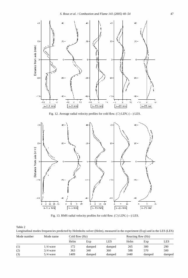
ulations indicate that the spiral structure appearinFig. 14rotates around the burner axis at a frequeof 540 Hz. Measurements performed inside the chber reveal a dominant frequency around 510 Hz.
The Helmholtz solver confirms the hydrodynamnature of the 540 Hz frequency which does notpear as an acoustic eigenmode: the acoustic modthe combustor obtained with AVSP are listed inTa-ble 3and none of them matches the 540 Hz frequen
The first acoustic mode ofTable 3(172 Hz) is notobserved in LES nor in experiments: this mode is sble. However, the second mode (363 Hz) is indeidentified in experiments (around 340 Hz) and in L(around 360 Hz) but only in the plenum and in thehaust pipe. This mode is actually present everywhin the device but it is dominated by the PVC signinside the first part of the chamber.Fig. 15shows ex-perimental and numerical pressure spectra meas
46 S. Roux et al. / Combustion and Flame 141 (2005) 40–54
Fig. 10. Average azimuthal velocity profiles for cold flow. (!) LDV, (—) LES.
in the plenum and in the chamber and confirms tthese two modes exist simultaneously but not insame places.
To extend the analysis of these modes and ecially to look at their spatial structure, it is not eato use measurements since they would require mple simultaneous pressure probes. It is more connient to rely on LES and acoustic calculations:
computed both with LES and with the acoustic solare presented inFig. 16. Since the 3/4 wave mode haa long wavelength compared to the chamber, thisis obtained in the LES and in the Helmholtz solverdisplaying local RMS pressure versusx coordinate.In Fig. 16, LES shows RMS of the whole pressusignal whereas the acoustic solver displays onlyRMS acoustic structure of the 363 Hz mode. The tcodes give similar pressure amplitudes in the plen
S. Roux et al. / Combustion and Flame 141 (2005) 40–54 47
S (LES)
ped
Fig. 12. Average radial velocity profiles for cold flow. (!) LDV, (—) LES.
(x < −0.05 m) and in the exhaust (x > 0.05 m), indi-cating the acoustic nature of the pressure fluctuatin these regions. However, in the swirler and infirst half of the chamber (−0.05 m< x < 0.05 m),the pressure fluctuations given by LES are larger tthe acoustic predictions of the Helmholtz solver: thfluctuations are due to the PVC at 540 Hz. The P
Fig. 16. Pressure fluctuations amplitude obtained by L(circles) and acoustic analysis (solid line) code for cflow.
acts acoustically like a rotating solid placed in tflow: this dipole radiates weakly outside of the chaber. This explains why the acoustic mode at 360is visible and unaffected in the plenum and in thehaust.
High levels of RMS velocity are found also in thswirler (not shown here) confirming the requiremefor an entrance to exhaust computation: there issection in the swirler or in the chamber inlet whicould possibly be used to specify inlet boundary cditions and reduce the size of the computationalmain.
In summary, for cold flow, two modes coexist:low-amplitude acoustic (3/4 wave) mode at 360 Heverywhere in the device and a strong hydrodynamode at 540 Hz due to the PVC, localized nearburner inlet (0< x < 5 cm).
6. Reacting flow
The reacting case corresponds to an equivaleratio of 0.75, an air flow rate of 12 g/s, and a ther-mal power of 27 kW. A snapshot of an instanneous temperature isosurface (Fig. 17) reveals a compact flame located close to the burner inlet.Fig. 18shows the pseudo-streamline pattern on thex–r planebased on the mean axial and radial velocity coponents. A central toroidal recirculation zone istablished in the wake of the center body undereffect of the swirling flow. A corner recirculatiozone is formed downstream of the backward-facstep.
S. Roux et al. / Combustion and Flame 141 (2005) 40–54 49
.
yed
sec-to
it-on
era-
red
-ntal-onmsve-ndhetheatthe
thetheanre
s inforver-vre-ss
ultse--
ns,
Fig. 17. Instantaneous 1250 K isosurface (LES data)
Fig. 18. Meanx–r pseudo-streamline pattern.
6.1. Average profiles
Mean and RMS temperature profiles are displain Fig. 19. As expected from the snapshot ofFig. 17,combustion is nearly finished atx = 35 mm and nofresh gases are found (in the mean) beyond thistion. RMS temperature levels are quite high closethe burner inlet (300 K), indicating a strong intermtency and flame flapping in this zone. No comparis
is possible with experiments here because temptures have not been measured yet.
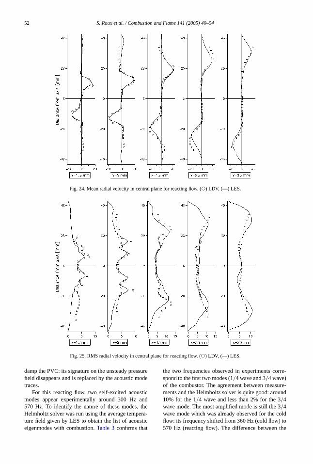
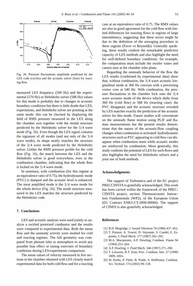
The velocity fields, however, have been measuand are presented inFigs. 20(mean axial),21 (RMSaxial),22 (mean tangential),23 (RMS tangential),24(mean radial),25 (RMS radial). The overall agreement between mean LES results and experimedata is good.Table 4gives an overview of the quantitative accuracy of the LES prediction. It is baseda comparison between LES and LDV results in terof the maximum mean/rms axial/tangential/radiallocity (in percentage of their maximum value) atheir position (in percentage of the half-width of tcombustion chamber). The rather low accuracy ofRMS maximum values may come from the fact ththe subgrid-scale fluctuations are not included inRMS values shown in the present paper.
The LES captures both the mean values andfluctuations precisely, except in a zone close toburner inlet. This lack of precision could be due toinsufficient mesh resolution in this region but a mofundamental issue linked to averaging techniquenonconstant density flows is probably responsiblethe discrepancy observed in these regions: LES aages are obtained using time averages of the Fafiltered LES quantities while the averaging proce(Favre or Reynolds) used for experimental res(LDV measurements) is often difficult to qualify bcause of data sampling[9,39]. Most zones where experiments and LES do not match inFigs. 21 or 23areregions where the RMS temperature (Fig. 19) is large,i.e., zones with strong intermittency. In these regio
Fig. 19. Mean (solid line) and RMS (circles) temperature in the central plane of the combustor (LES data).
50 S. Roux et al. / Combustion and Flame 141 (2005) 40–54
l
Fig. 20. Mean axial velocity in the central plane for reacting flow. (!) LDV, (—) LES.
Fig. 21. RMS axial velocity in the central plane for reacting flow (!) LDV, (—) LES.
Table 4Accuracy of the LES/experiment comparison for reacting case
Mean velocity RMS velocity
Axial Tangential Radial Axial Tangential Radia
Max. value 6% 5% 11% 33% 16% 19%
Max. value position 1% 3% 5% 7% 8% 0%
S. Roux et al. / Combustion and Flame 141 (2005) 40–54 51
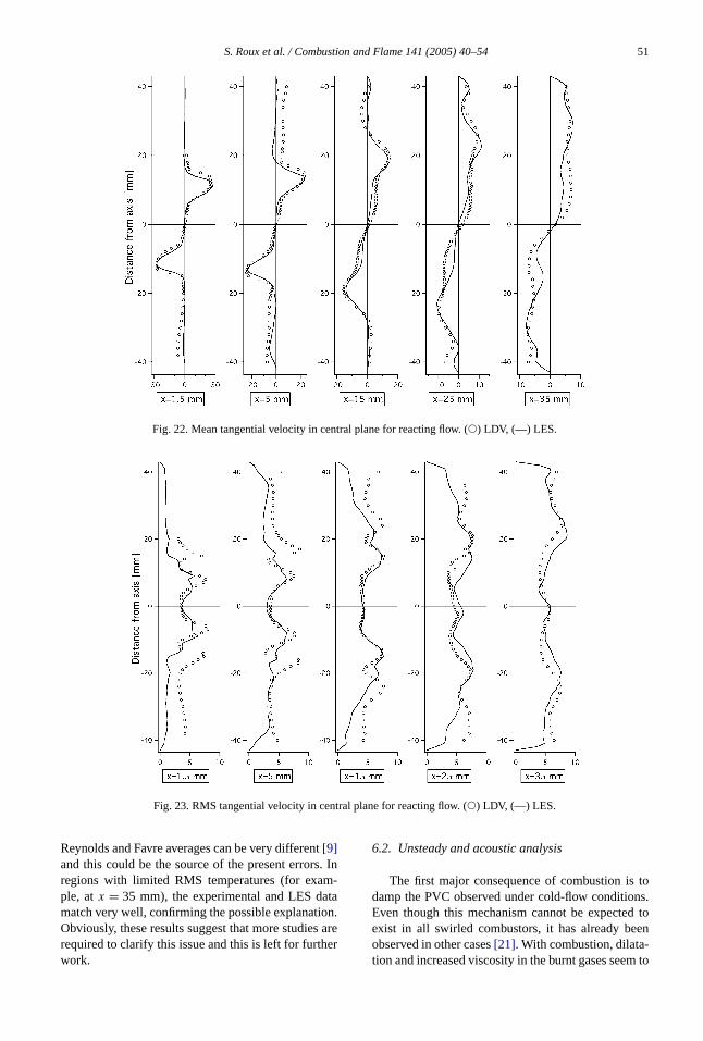
Fig. 22. Mean tangential velocity in central plane for reacting flow. (!) LDV, (—) LES.
Fig. 23. RMS tangential velocity in central plane for reacting flow. (!) LDV, (—) LES.
t. In
m-tan.are
er
tons.d toen
-m to
Reynolds and Favre averages can be very differen[9]and this could be the source of the present errorsregions with limited RMS temperatures (for exaple, atx = 35 mm), the experimental and LES damatch very well, confirming the possible explanatioObviously, these results suggest that more studiesrequired to clarify this issue and this is left for furthwork.
6.2. Unsteady and acoustic analysis
The first major consequence of combustion isdamp the PVC observed under cold-flow conditioEven though this mechanism cannot be expecteexist in all swirled combustors, it has already beobserved in other cases[21]. With combustion, dilatation and increased viscosity in the burnt gases see
52 S. Roux et al. / Combustion and Flame 141 (2005) 40–54
Fig. 24. Mean radial velocity in central plane for reacting flow. (!) LDV, (—) LES.
Fig. 25. RMS radial velocity in central plane for reacting flow. (!) LDV, (—) LES.
sureode
ticandtheera-tic
rre-
ure-nd
oldothe
damp the PVC: its signature on the unsteady presfield disappears and is replaced by the acoustic mtraces.
For this reacting flow, two self-excited acousmodes appear experimentally around 300 Hz570 Hz. To identify the nature of these modes,Helmholtz solver was run using the average tempture field given by LES to obtain the list of acouseigenmodes with combustion.Table 3confirms that
the two frequencies observed in experiments cospond to the first two modes (1/4 wave and 3/4 wave)of the combustor. The agreement between measments and the Helmholtz solver is quite good: arou10% for the 1/4 wave and less than 2% for the 3/4wave mode. The most amplified mode is still the 3/4wave mode which was already observed for the cflow: its frequency shifted from 360 Hz (cold flow) t570 Hz (reacting flow). The difference between
S. Roux et al. / Combustion and Flame 141 (2005) 40–54 53
thect-
eri-essticS,thethengure
ns
tureltzldheheow
atdeed.
-by
an-ultseanldm-nyary
ec-tching
luesm-gebein
eak-tiveed
le,nd
theow-ings-
mhealedsticate
a-on-
ingmicdis-des
hisndd a
ectrkC-c-
ionort
2.s-
4
8)
st.
Fig. 26. Pressure fluctuations amplitude predicted byLES code (circles) and the acoustic solver (line) for reaing flow.
measured LES frequency (500 Hz) and the expmental (570 Hz) or Helmholtz solver (588 Hz) valufor this mode is probably due to changes in acouboundary conditions but there is little doubt that LEexperiments, and Helmholtz solver are pointing atsame mode: this can be checked by displayingfield of RMS pressure measured in the LES alothe chamber axis together with the modal structpredicted by the Helmholtz solver for the 3/4 wavemode (Fig. 26). Even though the LES signal contaithe signature of all modes (and not only of the 3/4wave mode), its shape neatly matches the strucof the 3/4 wave mode predicted by the Helmhosolver. Unlike the RMS pressure profile for the coflow (Fig. 16), the match between the LES and tHelmholtz solver is good everywhere, even in tcombustion chamber, indicating that the whole flis locked on the 3/4 wave mode.
In summary, with combustion (for this regimean equivalence ratio of 0.75), the hydrodynamic mo(PVC) is damped and the acoustic level is enhancThe most amplified mode is the 3/4 wave mode forthe whole device (Fig. 26). The mode structure measured in the LES matches the structure predictedthe Helmholtz code.
7. Conclusions
LES and acoustic analysis were used jointly toalyze a swirled premixed combustor and the reswere compared to experimental data. Both the mflow and the unsteady activity were studied for coand reacting regimes. The full geometry was coputed from plenum inlet to atmosphere to avoid apossible bias effect or tuning exercises of boundconditions during LES/experiments comparison.
The mean values of velocity measured in five stions in the chamber obtained with LES closely maexperimental data for both cold flow and for a react
case at an equivalence ratio of 0.75. The RMS vaare also in good agreement for the cold flow with liited differences for reacting flows in regions of larintermittency, suggesting that these errors mightdue to the definition of the averaging procedurethese regions (Favre vs Reynolds). Generally sping, these results confirm the remarkable prediccapacity of LES methods and also highlight the nefor well-defined boundary conditions: for exampthe computation must include the swirler vanes acannot start at the chamber inlet plane.
Regarding the unsteady behavior of the flowLES results (confirmed by experimental data) shthat, without combustion, the 3/4 wave acoustic longitudinal mode at 360 Hz coexists with a precessvortex core at 540 Hz. With combustion, the presure fluctuations in the chamber lock onto the 3/4wave acoustic mode of the device which shifts fro360 Hz (cold flow) to 588 Hz (reacting case): tPVC disappears and the acoustic structure reveby LES matches exactly the prediction of the acousolver for this mode. Future studies will concentron the unsteady flame motion using PLIF and Rman measurements but the present results demstrate that the nature of the acoustic/flow couplchanges when combustion is activated: hydrodynastructures such as PVC appearing in cold flow canappear when combustion starts while acoustic moare reinforced by combustion. More generally, tstudy confirms the potential of LES for such flows aalso highlights the need for Helmholtz solvers anjoint use of both methods.
Acknowledgments
The support of Turbomeca and of the EC projPRECCINSTA is gratefully acknowledged. This wohas been carried within the framework of the PRECINSTA project, section Thermoacoustic Interation Fundamentals (WP2), of the European Un(EU Contract ENK5-CT-2000-00060). The suppof CINES is also gratefully acknowledged.
References
[1] B.D. Mugridge, J. Sound Vibration 70 (1980) 437–45[2] T. Poinsot, A. Trouvé, D. Veynante, S. Candel, E. E
posito, J. Fluid Mech. 177 (1987) 265–292.[3] M.A. Macquisten, A.P. Dowling, Combust. Flame 9
(1994) 253–264.[4] A.P. Dowling, J. Fluid Mech. 346 (1997) 271–290.[5] T. Lieuwen, B.T. Zinn, Proc. Combust. Inst. 27 (199
1809–1816.[6] W. Krebs, P. Flohr, B. Prade, S. Hoffmann, Combu
Sci. Technol. 174 (2002) 99–128.
54 S. Roux et al. / Combustion and Flame 141 (2005) 40–54
,t-
cal
0)
att-
c.ibi-
T-
s-
88)
0)
p.
7.d-nte,
w
st.
119
m-
iv.
ust.
0)
r-, in
9)
lu-
–
r 2
o-c-
–
76
87
[7] S. Candel, Proc. Combust. Inst. 29 (2002) 1–28.[8] D.G. Crighton, A. Dowling, J.F. Williams, M. Heckl
F. Leppington, Modern Methods in Analytical Acousics, Springer-Verlag, New York, 1992.
[9] T. Poinsot, D. Veynante, Theoretical and NumeriCombustion, Edwards, 2001.
[10] T. Lieuwen, B.T. Zinn, J. Sound Vibration 235 (200405–414.
[11] C.O. Paschereit, W. Polifke, B. Schuermans, O. Mson, J. Eng. Gas Turb. Power 124 (2002) 239–247.
[12] G. Walz, W. Krebs, S. Hoffmann, H. Judith, in: ProInt. Gas Turbine and Aeroengine Congress and Exhtion, 1999.
[13] S.R. Stow, A.P. Dowling, Proc. ASME Paper 2003-G38168, 2003.
[14] S. Zikikout, S. Candel, T. Poinsot, A. Trouvé, E. Espoito, Proc. Combust. Inst. 21 (1986) 1427–1434.
[15] F.E.C. Culick, Astronautica Acta 3 (1976) 714–757.[16] T. Poinsot, S. Candel, Combust. Sci. Technol. 61 (19
121–153.[17] F.E.C. Culick, AIAA J. 32 (1994) 146–169.[18] H. Forkel, J. Janicka, Flow Turb. Combust. 65 (200
163–175.[19] Y. Huang, H.G. Sung, S.Y. Hsieh, V. Yang, J. Pro
Power 19 (2003) 782–794.[20] C.D. Pierce, P. Moin, J. Fluid Mech. 504 (2004) 73–9[21] L. Selle, G. Lartigue, T. Poinsot, R. Koch, K.-U. Schil
macher, W. Krebs, B. Prade, P. Kaufmann, D. VeynaCombust. Flame 137 (2004) 489–505.
[22] C. Angelberger, F. Egolfopoulos, D. Veynante, FloTurb. Combust. 65 (2000) 205–222.
[23] O. Lucca-Negro, T. O’Doherty, Prog. Energy CombuSci. 27 (2001) 431–481.