4 th International Conference On Building Energy, Environment Study on Performance of A Novel Energy‐Efficient Heat Pump System Using Liquid Desiccant N. Shan 1 , Y. Yin 1,2* , F. Zhang 1 1 School of Energy and Environment Southeast University, 2 Sipailou Road, Nanjing 210096, China 2 MOE Key Laboratory of Energy Thermal Conversion and Control, Southeast University, 2 Sipailou Road, Nanjing 210096, China * SUMMARY In this paper, a novel heat pump system is proposed, which operates as a heat-source tower heat pump with no frosting in winter, and as a hybrid refrigerant system consisting of a conventional chiller and a liquid desiccant dehumidification and evaporative cooling subsystem in summer. Mathematical model of the proposed system operating in summer was established and the effects of key parameters, including solution to refrigerant flow ratio, proportion of condensation heat utilization and ambient parameters, on the cooling performance were investigated. The results show that the COP and ECOP of the hybrid refrigerant system are higher than conventional systems by increasing 13.4% and 10.3% respectively under the typical summer condition of Nanjing. The recommended range of flow ratio is from 1.2 to 6 and that for condensation heat recovery proportion is from 16% to 40%. Besides, the proposed system is more superior than the conventional ones when applied in hot and humid region. INTRODUCTION The climate in south-central China, characterized by hot summer and raw winter, provides harsh thermal environment for the residents and makes it considerably energy-intensive to improve the indoor thermal comforts. The conventional cooling and heating source of air-conditioning systems all show their own disadvantages or limitations when being used in this area (Huang et al. 2017), including the frosting problem or low cooling efficiency of air source heat pumps(ASHP), the idle problem of chillers in water chiller with boiler systems in winter, and the topographical limitations or high initial investment in ground source heat pumps. The heating tower heat pump (HTHP) becomes popular in recent studies as it takes advantage of the high cooling efficiency of water-cooled chillers in summer, and could work continuously without frosting surface by using air as a low- potential heat source from reversibly used cooling tower that replaces its working fluid with the solution. It is theoretically proved by Li et al. (2011) that HTHP could operate in higher efficiency continuously in winter compared to the widely used ASHP. Experimental results provided by Li et al. (2011) shows that the COP (coefficient of performance) and SEER (seasonal energy efficiency ratio) of HTHP ranges from 2.358 to 4.34 and 2.45 to 3.45 respectively when the outdoor temperature varies from -1 ºC to 5 ºC and the relative humidity changes from 71%~95%. Wen et al. (2012) and Huang et al. (2017) pointed out that the heat transfer capacity of the packing towers in summer is much larger than that in winter, resulting that HTHP requires more packing towers than conventional water chiller with boiler systems. Although HTHP is a perfect substitute for ASHP or water chiller with boiler systems in winter, the surplus packing towers than conventional water chillers do not benefit the system in summer. For one thing, the condensing temperature would not drop significantly as the temperature of the cooling water is limited by the wet-bulb temperature; For another, the use of more pumps and fans in the extra towers would add up to the power consumption of the whole system, which is unfavourable for improving the efficiency of the whole system. Some researchers make the use of the condensation heat for improving the comprehensive performance of the cooling system. Apart from serving hot water(Lee and John 1995, Ji et al. 2003), condensation heat is also recycled as the heat source of desiccant regeneration in temperature and humidity independent control systems (Dai et al. 2001) However, the processed air in the dehumidification system driven by condensation could meet requirements for air conditioning only when the condensation heat is upgraded by heat pump (Chen et al. 2016,2014) or combined with higher grade of heat source like solar energy (Sukamongkol et al. 2010). Further cooling of the refrigerant leaving the condenser is believed to be beneficial for the performance of the refrigerating system by increasing the cooling capacity as well as reducing thermodynamic loss in the throttling process. The subcooling capacity of the conventional subcooling methods, including suction-line heat exchanger, mechanical subcooler (Park et al. 2015) and subcoolers based on cool storage (Liu et al. 2011), is basically produced by electricity and is not electric-efficient. In recent years, a combination of the low-grade heat-driven desiccant cooling system with the conventional electric-driven vapor-compression refrigeration system shows promising energy-saving potentials. Xu et al. (2016) showed that the COP of an absorption-compression cascade refrigeration, where the low-grade heat of absorption subsystem is used to subcool the compression subsystem, is 38% higher than that of compression auto- cascade cycle. Solar energy is often used as the generation source for the absorption subsystem in the above system (Li et al. 2016). Actually, low grade heat can also be produced by the Dehumidifier-Evaporator-Regenerator system(DER) (Hellmann and Grossman 1994, Pohl et al. 1997) generated by much lower grade heat that ranges from 40 ºC to 60 ºC. In the DER system, the dry air from the outlet of the dehumidifier was used to produce chilled water through directive evaporating process. She et al. (2014) first investigated the performance of a hybrid refrigerant system combining the DER with the air-cooled vapor-compression refrigeration cycle and the thermodynamic analysis shows ISBN: 978-0-646-98213-7 COBEE2018-Paper285 page 862
Transcript
4th International Conference On Building Energy, Environment
Study on Performance of A Novel Energy‐Efficient Heat Pump System Using Liquid Desiccant
N. Shan 1, Y. Yin 1,2* , F. Zhang 1 1School of Energy and Environment
Southeast University, 2 Sipailou Road, Nanjing 210096, China 2 MOE Key Laboratory of Energy Thermal Conversion and Control,
Southeast University, 2 Sipailou Road, Nanjing 210096, China *
SUMMARY In this paper, a novel heat pump system is proposed, which operates as a heat-source tower heat pump with no frosting in winter, and as a hybrid refrigerant system consisting of a conventional chiller and a liquid desiccant dehumidification and evaporative cooling subsystem in summer. Mathematical model of the proposed system operating in summer was established and the effects of key parameters, including solution to refrigerant flow ratio, proportion of condensation heat utilization and ambient parameters, on the cooling performance were investigated. The results show that the COP and ECOP of the hybrid refrigerant system are higher than conventional systems by increasing 13.4% and 10.3% respectively under the typical summer condition of Nanjing. The recommended range of flow ratio is from 1.2 to 6 and that for condensation heat recovery proportion is from 16% to 40%. Besides, the proposed system is more superior than the conventional ones when applied in hot and humid region.
INTRODUCTION
The climate in south-central China, characterized by hot summer and raw winter, provides harsh thermal environment for the residents and makes it considerably energy-intensive to improve the indoor thermal comforts. The conventional cooling and heating source of air-conditioning systems all show their own disadvantages or limitations when being used in this area (Huang et al. 2017), including the frosting problem or low cooling efficiency of air source heat pumps(ASHP), the idle problem of chillers in water chiller with boiler systems in winter, and the topographical limitations or high initial investment in ground source heat pumps.
The heating tower heat pump (HTHP) becomes popular in recent studies as it takes advantage of the high cooling efficiency of water-cooled chillers in summer, and could work continuously without frosting surface by using air as a low-potential heat source from reversibly used cooling tower that replaces its working fluid with the solution. It is theoretically proved by Li et al. (2011) that HTHP could operate in higher efficiency continuously in winter compared to the widely used ASHP. Experimental results provided by Li et al. (2011) shows that the COP (coefficient of performance) and SEER (seasonal energy efficiency ratio) of HTHP ranges from 2.358 to 4.34 and 2.45 to 3.45 respectively when the outdoor temperature varies from -1 ºC to 5 ºC and the relative humidity changes from 71%~95%. Wen et al. (2012) and Huang et al. (2017) pointed out that the heat transfer capacity of the packing towers in summer is much larger than that in winter, resulting that HTHP requires more
packing towers than conventional water chiller with boiler systems. Although HTHP is a perfect substitute for ASHP or water chiller with boiler systems in winter, the surplus packing towers than conventional water chillers do not benefit the system in summer. For one thing, the condensing temperature would not drop significantly as the temperature of the cooling water is limited by the wet-bulb temperature; For another, the use of more pumps and fans in the extra towers would add up to the power consumption of the whole system, which is unfavourable for improving the efficiency of the whole system.
Some researchers make the use of the condensation heat for improving the comprehensive performance of the cooling system. Apart from serving hot water(Lee and John 1995, Ji et al. 2003), condensation heat is also recycled as the heat source of desiccant regeneration in temperature and humidity independent control systems (Dai et al. 2001) However, the processed air in the dehumidification system driven by condensation could meet requirements for air conditioning only when the condensation heat is upgraded by heat pump (Chen et al. 2016,2014) or combined with higher grade of heat source like solar energy (Sukamongkol et al. 2010).
Further cooling of the refrigerant leaving the condenser is believed to be beneficial for the performance of the refrigerating system by increasing the cooling capacity as well as reducing thermodynamic loss in the throttling process. The subcooling capacity of the conventional subcooling methods, including suction-line heat exchanger, mechanical subcooler (Park et al. 2015) and subcoolers based on cool storage (Liu et al. 2011), is basically produced by electricity and is not electric-efficient. In recent years, a combination of the low-grade heat-driven desiccant cooling system with the conventional electric-driven vapor-compression refrigeration system shows promising energy-saving potentials. Xu et al. (2016) showed that the COP of an absorption-compression cascade refrigeration, where the low-grade heat of absorption subsystem is used to subcool the compression subsystem, is 38% higher than that of compression auto-cascade cycle. Solar energy is often used as the generation source for the absorption subsystem in the above system (Li et al. 2016). Actually, low grade heat can also be produced by the Dehumidifier-Evaporator-Regenerator system(DER) (Hellmann and Grossman 1994, Pohl et al. 1997) generated by much lower grade heat that ranges from 40 ºC to 60 ºC. In the DER system, the dry air from the outlet of the dehumidifier was used to produce chilled water through directive evaporating process. She et al. (2014) first investigated the performance of a hybrid refrigerant system combining the DER with the air-cooled vapor-compression refrigeration cycle and the thermodynamic analysis shows
4th International Conference On Building Energy, Environment
that the hybrid cooling system could achieve higher cooling efficiency with the maximum COP using hot air and ambient air for generation increasing by 18.8% and 16.3% respectively. However, few researches of this type of efficient hybrid refrigeration system have been done so far.
In this paper, a novel efficient heat pump system using liquid desiccant is proposed to solve the idle problem of packing towers of HTHP system and improve its refrigerating efficiency in summer. In winter, the novel operates as the HTHP and while in summer, it works as a hybrid refrigerant system consisting of a vapor-compression chiller, a liquid desiccant cycle and an indirect evaporative cooler. The condensation heat in summer was also used for the regeneration process of the liquid desiccant. The present study will investigate its potential of performance improvement compared to conventional water-cooled chillers and analyse several key parameters to enhance the performance of the proposed system.
METHODOLOGY
System description
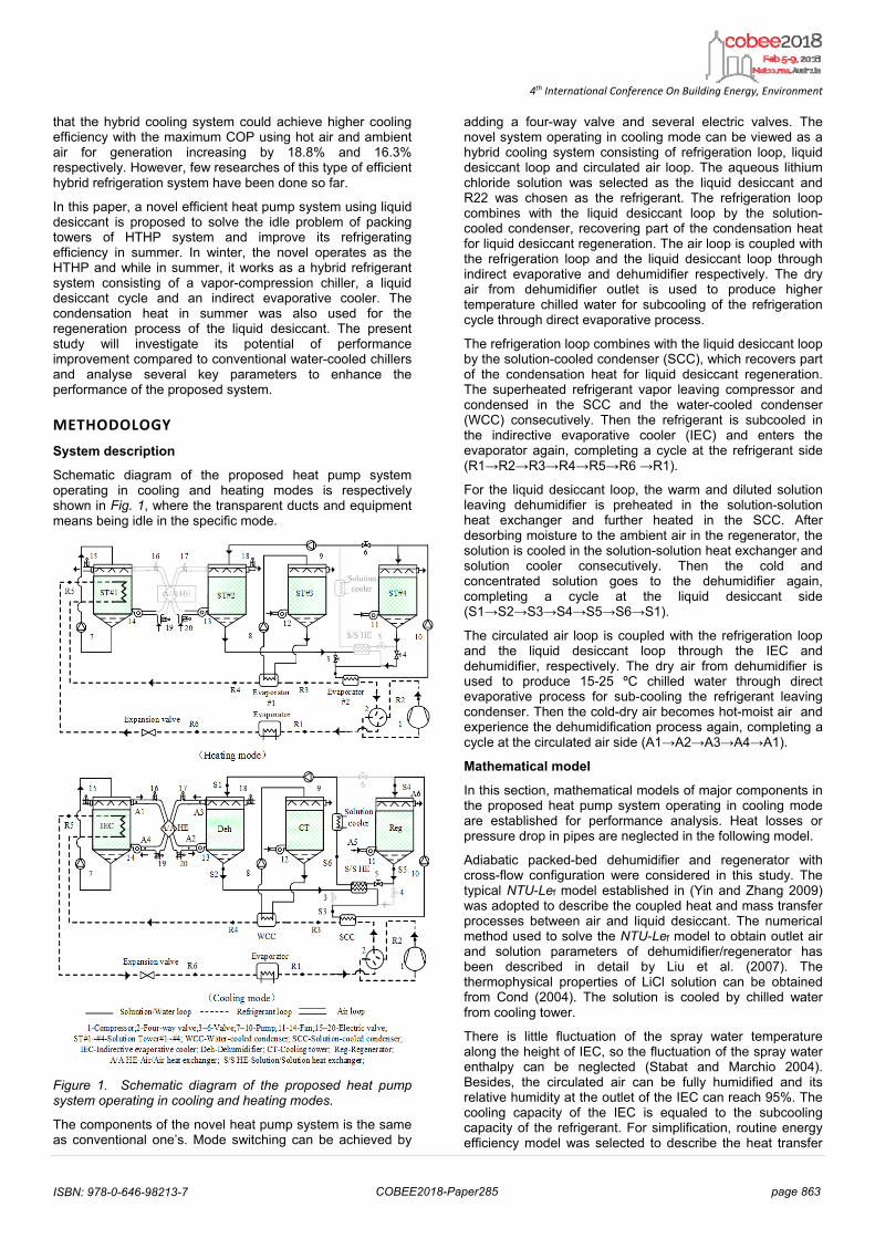
Schematic diagram of the proposed heat pump system operating in cooling and heating modes is respectively shown in Fig. 1, where the transparent ducts and equipment means being idle in the specific mode.
Figure 1. Schematic diagram of the proposed heat pump system operating in cooling and heating modes.
The components of the novel heat pump system is the same as conventional one’s. Mode switching can be achieved by
adding a four-way valve and several electric valves. The novel system operating in cooling mode can be viewed as a hybrid cooling system consisting of refrigeration loop, liquid desiccant loop and circulated air loop. The aqueous lithium chloride solution was selected as the liquid desiccant and R22 was chosen as the refrigerant. The refrigeration loop combines with the liquid desiccant loop by the solution-cooled condenser, recovering part of the condensation heat for liquid desiccant regeneration. The air loop is coupled with the refrigeration loop and the liquid desiccant loop through indirect evaporative and dehumidifier respectively. The dry air from dehumidifier outlet is used to produce higher temperature chilled water for subcooling of the refrigeration cycle through direct evaporative process.
The refrigeration loop combines with the liquid desiccant loop by the solution-cooled condenser (SCC), which recovers part of the condensation heat for liquid desiccant regeneration. The superheated refrigerant vapor leaving compressor and condensed in the SCC and the water-cooled condenser (WCC) consecutively. Then the refrigerant is subcooled in the indirective evaporative cooler (IEC) and enters the evaporator again, completing a cycle at the refrigerant side (R1→R2→R3→R4→R5→R6 →R1).
For the liquid desiccant loop, the warm and diluted solution leaving dehumidifier is preheated in the solution-solution heat exchanger and further heated in the SCC. After desorbing moisture to the ambient air in the regenerator, the solution is cooled in the solution-solution heat exchanger and solution cooler consecutively. Then the cold and concentrated solution goes to the dehumidifier again, completing a cycle at the liquid desiccant side (S1→S2→S3→S4→S5→S6→S1).
The circulated air loop is coupled with the refrigeration loop and the liquid desiccant loop through the IEC and dehumidifier, respectively. The dry air from dehumidifier is used to produce 15-25 ºC chilled water through direct evaporative process for sub-cooling the refrigerant leaving condenser. Then the cold-dry air becomes hot-moist air and experience the dehumidification process again, completing a cycle at the circulated air side (A1→A2→A3→A4→A1).
Mathematical model
In this section, mathematical models of major components in the proposed heat pump system operating in cooling mode are established for performance analysis. Heat losses or pressure drop in pipes are neglected in the following model.
Adiabatic packed-bed dehumidifier and regenerator with cross-flow configuration were considered in this study. The typical NTU-Lef model established in (Yin and Zhang 2009) was adopted to describe the coupled heat and mass transfer processes between air and liquid desiccant. The numerical method used to solve the NTU-Lef model to obtain outlet air and solution parameters of dehumidifier/regenerator has been described in detail by Liu et al. (2007). The thermophysical properties of LiCl solution can be obtained from Cond (2004). The solution is cooled by chilled water from cooling tower.
There is little fluctuation of the spray water temperature along the height of IEC, so the fluctuation of the spray water enthalpy can be neglected (Stabat and Marchio 2004). Besides, the circulated air can be fully humidified and its relative humidity at the outlet of the IEC can reach 95%. The cooling capacity of the IEC is equaled to the subcooling capacity of the refrigerant. For simplification, routine energy efficiency model was selected to describe the heat transfer
4th International Conference On Building Energy, Environment
process in solution-solution heat exchanger and air-air heat exchanger, with 0.8 and 0.6 respectively.
In refrigerant cycle, the evaporating temperature of the refrigerant is set to 5 ºC, and its superheating degree at the inlet of the compressor is set at 5 ºC. The refrigerant temperature at the outlet of water-cooled condenser is assumed to equal to the condensing temperature, and the stated of the refrigerant is saturated liquid. The thermophysical properties of the refrigerant R22 were calculated by using REFPROP 8.0. For the compressor, as shown in Fig. 2, point 1 to point 2 represents the actual process when taking the indicated compression efficiency and the motor efficiency into consideration.
Figure 2. Pressure-enthalpy diagram of the vapor compression refrigeration cycle in the prosed system
The sensible condensation heat and a small part of the latent condensation heat is rejected to solution-cooled condenser and the rest is rejected to the water-cooled condenser. The condensing temperature Tc can be calculated by Eq(5):
w,in,cond w,out,cond w,out,cond w,in,condc
w,out,cond w,in,cond
exp(( ) / 6)1 exp(( ) / 6)
T T T TT
T T
(1)
Where the Tw,in,cond and Tw,out,cond stand for inlet and outlet temperature of the cooling water for condensing, respectively.
The condensation heat rejected to solution-cooled condenser is divided into two parts including sensible part (Qc,sen) and latent part 1(Qc,lat,1), and the heat rejected to water-cooled condenser is Qc,lat,2, as is shown in Fig.2. The SCC and the WCC are assumed to work in ideal conditions, so the outlet solution temperature can be calculated when the parameters of the refrigerant cycle are determined, based on the principle of energy balance. The proportion of the condensation rejected to the solution-cooled condenser is defined as Rcond as shown in Eq (2):
c,sen c,lat,1cond
c,sen c,lat,1 c,lat,2
+=
+ +Q Q
RQ Q Q
(2)
There are five pumps, including dehumidifier and regenerator pumps, IEC pump, water pump in cooling tower, and their power was calculated using Eq. (3). It should be mentioned that the power consumed by the pump (Npump) in the cooling tower should include two parts, as the pump provides cooling water for the solution cooler as well as the water-cooled condenser, The pump efficiency is set to 80% and the design pump heads of the cooling tower and regenerator pumps were set to 180kPa while 15kPa was assumed for the dehumidifier and IEC pumps.
fluidV PN
(3)
Where N is power, ∆P is pressure drop and η is efficiency. There are four fans, including fans serves for the dehumidifier, regenerator, cooling tower and IEC, and the fan power (Nfan) was estimated using Eq. (3). The fan efficiency is set to 60% and the design pressure drop of each fan is listed in Table 1 according to Ham et al. (2016).
Table 1. Fan pressure drop under design flow
Component Design pressure drop
Specification
Regenerator fan 60Pa Reg:60Pa Cooling tower fan 60Pa CT:60Pa Dehumidifier fan 188Pa Deh:60Pa
A/A HE:128PaIEC fan 160Pa IEC:32Pa
A/A HE:128Pa
Performance index
Three performance indexes were used in this study to give a comprehensive evaluation of the thermal performance of the proposed heat pump system operating in cooing mode. These indexes are as follows:
(1) Subcooling degrees (∆T) is defined as the temperaturedifference between condensing temperature (Tc) and therefrigerant temperature leaving IEC (Tref,IEC,out) .
c ref,IEC,outΔ =T T T (4)
(2) Specific refrigerant capacity qe is calculated by theenthalpy difference between outlet (href,eav,out) and inlet(href,eva,in) refrigerant of the evaporator.
ref,eva,out ref,eva,ineq h h (5)
(3) Coefficient of performance (COP) is defined as ratiobetween the total cooling capacity (Qe) and the powerconsumption of compressor (Ncom).
e
com
QCOP
N (6)
(4) Electric coefficient of performance (ECOP) is defined asthe ratio between the total cooling capacity (Qe) and thetotal power consumption (Ntotal)
e
totalECOP Q
N (7)
Where Ntotal can be calculated by Eq. (8):
total com fan pump=N N N N (8)
Simulation flowchart
Based on the above mathematical models, the flow chart for calculating the thermal performance of the whole system in cooling mode is shown in Fig. 3. It should be mentioned that the operating concentration of the liquid desiccant is not specified in advance, but determined by iterative calculation based on the mass balance between the dehumidifier and regenerator.
Figure 3. Calculation flow chart of the system performance in cooling mode
RESULTS AND DISCUSSION
In this section, the effects of several key parameters on the cooling performance of the proposed system served in Nanjing were investigated using MATLAB software. The typical outdoor air parameters, the geometrical size of several key components and the operating parameters under standard condition are listed in Table 2.
Table 2. Specified parameters used in simulation under design condition
Parameters Values
Tamb/ºC 35
RHamb/(gꞏkg-1) 60%
M ref,/(kgꞏs-1) 0.1253
FR 6
Size of dehumidifier/(L/m×W/m×H/m) 0.9×0.6×0.4 Size of regenerator/(L/m×W/m×H/m) 1×0.7×0.5 Specific surface area of structured packings /(m2ꞏm-3)
500
The size of IEC is assumed large enough to humidify the circulated air and the cooling tower is assumed large enough to produce cooling water, whose outlet temperature is assumed to be 4ºC higher than local wet-bulb temperature. Besides, the temperature of dehumidifier inlet solution is set
to 4 ºC higher than the wet-bulb temperature of the ambient air.
Effects of solution to refrigerant flow ratio(FR)
The FR is defined as the ratio of the solution mass flow rate of the solution at the dehumidifier inlet to the refrigerant mass flow rate. The effect of FR on thermal performance of the proposed system is shown in Fig. 7.
As shown in Fig. 4(a), the ∆T increases rapidly from 13.5 ºC to 16.5 ºC when FR increases from 1 to 9 , but then varies slightly when FR is larger than 9. While for the balanced operating solution concentration, it decreases sharply from 24.5% to 25.7% when FR increases from 1 to 9, then decreases slowly with the increasing of FR. Fig. 4(b) shows that qe,sc and ∆COP have the same trend as that of ∆T under the same outdoor condition However, ∆ECOP rises to its peak value of 10.3% at a small FR of 1.2 and then drops linearly when FR rises, shown in Fig. 4(c), owning to that the added power of pumps and fans becomes comparable to the subcooling capacity when FR is large enough.
1 3 5 7 9 11 13 15 17 1925.0
25.5
26.0
26.5
27.0
27.5
28.0
13
14
15
16
17(a)
FR
Xs_
bala
nce(%
)
T
sc(
C)
1 3 5 7 9 11 13 15 17 1917
18
19
20
21
22
11
12
13
14(b)
FR
qe,
sub(k
J/k
g)
C
OP
(%)
0.6 0.8 1.0 1.2 1.4 1.6 1.8 2.0 2.2 2.49.4
9.6
9.8
10.0
10.2
10.4(c)
E
CO
P(%
)
FR
Figure 4. Effects of FR on system performance
The increase of FR heightens the cooling capacity of the IEC whereas compromises the energy grade of the cooling capacity that could be produced by the liquid desiccant evaporative cooling subsystem. As can be seen from Fig.4, the increasing of FR has little contribution to the increase of the qe,sc or ∆T or COP and will reduce ∆ECOP dramatically when FR exceeds 7. Therefore, the value of FR should not be too large and the recommended value range would be given in the following discussion.
Effects of condensation heat recovery ratio (Rcond)
For each FR, the system achieves the maximal ∆T at the maximum of Rcond as is shown in Fig. 5(a). Fig. 5(b) presents the calculation of ∆qe and ∆ECOP when FR varies from 0.6 to 15 and Rcond varies from 10% to the maximum under the corresponding FR. ∆ECOP and ∆qe of the proposed system rises linearly to its peak value when Rcond increases to the maximum under a certain FR, and ∆ECOP drops below zero when the FR is larger than 9 under any Rcond or when Rcond exceeds 53%, which means the proposed system is no longer superior to conventional ones when ECOP is used as the only index for the cooling systems. To achieve more than 5% rise in ECOP as well as more than 10% increase of ∆qe, recommended value range of FR and Rcond are from 1.2 to 6 and from 16% to 40%, respectively.
4th International Conference On Building Energy, Environment
0.1 0.2 0.3 0.4 0.5 0.613
14
15
16
17(a)
Rcond
T
sc(
C)
Maximum condensation heat recovery ratio
0.0
0.5
1.0
1.5
2.0
2.5
AS
CC(m
2 )8.4 9.8 11.2 12.6 14.0
-15
-10
-5
0
5
10(b)
ECOP=0
Rcond
40%
30%
FR
12.1%
E
CO
P (
%)
qe(%)
0.6
10%
1.22.4
3
6
9
12
15 20%
15.8% 22.5%
25.6%
40%
53.3%
66.6%
77%
60%50%
Figure 5. Effect of Rcond on thermal performance of the system
Effects of ambient parameters on the subcooling degree
In the flowing analysis, FR remains unchanged at the value of 6 and the parameters is the same as the standard one listed in Table 2.
16 18 20 22 2414.5
15.0
15.5
16.0
16.5
17.0
17.5
28C 30C 32C 34C 36C
T
sc(
C)
ωamb
(g/kg)
Figure 6. Effects of temperature and humidity of ambient air on the subcooling degree.
Fig.6 shows the effects of temperature and humidity of ambient air on the subcooling degree(∆T). ∆T increases by 0.5 ºC every 2 ºC addition of the Tamb when Tamb was changed from 28 to 36 ºC, while it drops only 0.8 ºC when ωamb was varied from 16 to 24 g/kg. Therefore, ∆T was more sensitive to the change of Tamb than ωamb .
28 30 32 34 36140
150
160
170
180
190(a)
qe,sub
qe,con
Tamb
(C)
q e(k
J/k
g)
qe,new
18
20
22
24
26
28
qe,
sc(k
J/kg
)
16 18 20 22 24140
150
160
170
180
190(b)
ωamb
(g/kg)
qe,sc
qe,con
qe,nov
20
22
24
26
28
30
qe(k
J/k
g)
q e,sc
(kJ/
kg)
Figure7. Effects of temperature and humidity of ambient air on specific cooling capacity (qe) and subcooling capacity(qe,sc)
The qe,sc is the increase of the specific cooling capacity qe of the novel system in cooling mod compared to the conventional water-cooled chillers. Fig. 7 shows the variations of the qe,sc as well as the qe,nov and qe,conv under different ambient parameters. When the ωamb is set to 20 g/kg and the Tamb is changed from 28 ºC to 36 ºC, the qe,conv drops slightly from 161.6 to 159.1 kJ/kg while the qe,nov keeps almost unchanged and about 20.5 kJ/kg higher than the conventional one’s on average due to that the rising of qe,sc replenishes the reduction of the qe,nov of the novel system when the Tamb increases, as shown in Fig. 7(a). However, the qe,nov shares the small trend of declining slowly with the qe,conv while there is subtle variation in the qe,sc when Tamb keeps at the value of 36 ºC and the ωamb is increased from 16 g/kg to 24 g/kg, as shown in Fig. 7(b).
Because of the rising temperature of the cooling water influenced by the wet-bulb temperature, the condensing temperature is lifted when the temperature or the humidity
rises. For the refrigeration side, the rise of condensing temperature causes reduction in specific cooling capacity. While for the liquid descant side, the heightened condensing temperature would be beneficial to regeneration process by raising the solution temperature at the regenerator inlet. When the humidity keeps unchanged and the temperature of the ambient air increases, the regeneration process is enhanced by raising the temperature of the regeneration air as well as the solution temperature, contributing to the increase of the qe,sc. However, when the temperature keeps unchanged and the humidity of the ambient air increases, the regeneration air of higher humidity ratio would exert a negative effect on the regeneration process as it is becomes more difficult to desorb the diluted solution, counteracting the benefits brought by the increase of solution temperature at regenerator inlet and resulting a subtle variance in qe,sc. Therefore, the liquid desiccant side act as a buffer for the cooling capacity variations when the system experiences ambient parameters’ changes.
Effects of ambient parameters on COP and ∆COP
28 30 32 34 364.0
4.4
4.8
5.2
5.6
6.0
6.4
6.8
7.2(a)
COP
COPcon
COPnov
Tamb
(C)
CO
P
11
12
13
14
15
16
17
C
OP
(%)
16 18 20 22 244.44.85.25.66.06.46.87.27.6(b)
ωamb
(g/kg)
COP
COP2
COPnov
CO
P
12
13
14
15
16
17
18
CO
P(%
)
Figure 8. Effects of temperature and humidity of ambient air on coefficient of performance and its improvement
Fig. 8 shows that the rise of Tamb or ωamb would lead to the decline of the COP of both the novel system and the conventional ones due to the reduction of the qe and the increase of the power consumed by the compressor. When the ωamb is set to 20 g/kg and the Tamb is changed from 28 ºC to 36 ºC, the ∆COP is rising from 12.0% to 13.6% while it keeps unchanged at about 13.5% when the Tamb keeps at 36 ºC and the ωamb is ranged from 16 g/kg to 24 g/kg. The novel system in cooling mode and the conventional chiller raises the same amount of the power consumption in compressor when ambient parameters are changed., thus the trend of ∆COP when ambient parameters is varied can be explained with the former analysis of the qe. The slope of qe, nov changing with the temperature of the ambient air is smaller than the qe, conv while qe,nov shares the same trend with the qe,conv when the humidity of the ambient air is changed. Therefore, the COPnov drops more slightly than the COPconv does and the ∆COP is increasing when the ambient temperature is raised up while the ∆COP remain stable when the ambient humidity is changed, which means the novel system is more superior to the conventional chillers in high ambient temperature than that in low ones.
CONCLUSIONS
A novel energy-efficient heat pump system using liquid desiccant was proposed and the corresponding switching strategy in two modes was designed. In winter, the system can provide heating continuously with no frosting as a heat pump with heat-source towers, and in summer acts as a hybrid refrigerant system consisting of a conventional water-cooled chiller and a liquid desiccant dehumidification and evaporative cooling subsystem. A validated mathematical model was established to analyze the cooling performance of
4th International Conference On Building Energy, Environment
this system under typical summer condition of Nanjing and performance comparison between the novel system and the conventional system was conducted. The following conclusions can be drawn:
(1) The proposed system in cooling mode achieves higherCOP and ECOP than conventional water-cooled chillers, andthe maximum ∆T,∆COP and ∆ECOP is 16.5℃,13.4% and 10.3% under typical outdoor conditions respectively.
(2) As the FR and Rcond rise, the ∆COP increases while the∆ECOP drops. Therefore, FR and Rcond should be seriouslyselected and for the system described in this study, therecommended range of FR and Rcond are from 1.2 to 6 andfrom 16% to 40% respectively, achieving more than 5% risein ECOP as well as more than 10% increase in COP or in∆qe.
(3) Compared to the conventional water-cooled chillers, thecooling performance proposed system in cooling mode isless sensitive to the variation of the ambient parameters, asthe liquid desiccant evaporative cooling subsystem acts as abuffer to slow down the deterioration of the systemperformance when ambient parameters change for the worse.Therefore, the system shows superiority to the conventionalchillers when used in hot and humid regions.
REFERENCES
Chen, Y., Yin, Y., & Zhang, X. (2014). Performance analysis of a hybrid air-conditioning system dehumidified by liquid desiccant with low temperature and low concentration. Energy and Buildings, 77, 91-102.
Chen, Y., Zhang, X., & Yin, Y. (2016). Experimental and theoretical analysis of liquid desiccant dehumidification process based on an advanced hybrid air-conditioning system. Applied Thermal Engineering, 98, 387-399.
Conde, M. R. (2004). Properties of aqueous solutions of lithium and calcium chlorides: formulations for use in air conditioning equipment design. International Journal of Thermal Sciences, 43(4), 367-382.
Dai, Y. J., Wang, R. Z., Zhang, H. F., & Yu, J. D. (2001). Use of liquid desiccant cooling to improve the performance of vapor compression air conditioning. Applied Thermal Engineering, 21(12), 1185-1202.
Ham, S. W., Lee, S. J., & Jeong, J. W. (2016). Operating energy savings in a liquid desiccant and dew point evaporative cooling-assisted 100% outdoor air system. Energy and Buildings, 116, 535-552.
Hellmann, H. M., & Grossman, G. (1995). Simulation and analysis of an open-cycle dehumidifier-evaporator-regenerator (DER) absorption chiller for low-grade heat utilization. International journal of refrigeration, 18(3), 177-189.
Huang, S., Lv, Z., Liang, C., & Zhang, X. (2017). Experimental study of heat and mass transfer characteristics in a cross-flow heating tower. International Journal of Refrigeration, 77, 116-127.
Ji, J., Chow, T. T., Pei, G., Dong, J., & He, W. (2003). Domestic air-conditioner and integrated water heater for subtropical climate. Applied Thermal Engineering, 23(5), 581-592.
Lee, A. H., & Jones, J. W. (1996). Thermal performance of a residential desuperheater/water heater system. Energy conversion and management,37(4), 389-397.
Li, N., Zhang, W., Wang, Li., Liu, Q., & Hu, J. (2011, January). Experimental study on energy efficiency of heat-source tower heat pump units in winter condition. In Measuring Technology and Mechatronics Automation (ICMTMA), 2011 Third International Conference on (Vol. 2, pp. 135-138). IEEE.
Li, Z., Jing, Y., & Liu, J. (2016). Thermodynamic study of a novel solar LiBr/H 2 O absorption chiller. Energy and Buildings, 133, 565-576.
Liu, X. H., Jiang, Y., & Qu, K. Y. (2007). Heat and mass transfer model of cross flow liquid desiccant air dehumidifier/regenerator. Energy Conversion and Management, 48(2), 546-554.
Liu, X., Fang, G., & Chen, Z. (2011). Dynamic charging characteristics modeling of heat storage device with heat pipe. Applied Thermal Engineering,31(14), 2902-2908.
Liu, Y., Chen, G., Tang, L., & Liu, L. (2011). Analysis on performance of a novel frost-free air-source heat pump system. Building and Environment, 46(10), 2052-2059.
Park, C., Lee, H., Hwang, Y., & Radermacher, R. (2015). Recent advances in vapor compression cycle technologies. International Journal of Refrigeration,60, 118-134.
Pohl, J. P., Hellmann, H. M., & Grossman, G. (1998). Investigation and comparison of two configurations of a novel open-cycle absorption chiller.International journal of refrigeration, 21(2), 142-149.
She, X., Yin, Y., & Zhang, X. (2014). Thermodynamic analysis of a novel energy-efficient refrigeration system subcooled by liquid desiccant dehumidification and evaporation. Energy conversion and management, 78, 286-296.
Stabat, P., & Marchio, D. (2004). Simplified model for indirect-contact evaporative cooling-tower behaviour. Applied Energy, 78(4), 433-451.
Sukamongkol, Y., Chungpaibulpatana, S., Limmeechokchai, B., & Sripadungtham, P. (2010). Condenser heat recovery with a PV/T air heating collector to regenerate desiccant for reducing energy use of an air conditioning room. Energy and buildings, 42(3), 315-325.
Wen, X., Liang, C., & Zhang, X. (2012). Experimental study on heat transfer coefficient between air and liquid in the cross-flow heat-source tower. Building and Environment, 57, 205-213.
Xu, Y., Chen, G., Wang, Q., Han, X., Jiang, N., & Deng, S. (2016). Performance study on a low-temperature absorption–compression cascade refrigeration system driven by low-grade heat. Energy Conversion and Management, 119, 379-388.
Yin, Y., & Zhang, X. (2008). A new method for determining coupled heat and mass transfer coefficients between air and liquid desiccant. International journal of heat and mass transfer, 51(13), 3287-32.