Submission doc.: IEEE 802.11- 15/0627r0 May 2015 Hakan Persson, Ericsson Slide 1 Beam Selection for Hybrid MIMO Precoding Date: 2015-05-10 Authors: N am e A ffiliations A ddress Phone em ail Cagatay Capar Ericsson [email protected]Songnam H ong Ericsson songnam.hong@ ericsson.com D ennisH ui Ericsson [email protected]H akan Persson Ericsson [email protected]
Transcript
Submission
doc.: IEEE 802.11-15/0627r0May 2015
Hakan Persson, EricssonSlide 1
Beam Selection for Hybrid MIMO Precoding
Date: 2015-05-10
Name Affiliations Address Phone email Cagatay Capar Ericsson [email protected]
In this presentation, beam selection for hybrid precoding for 11ay is investigated. Our goal is to see if beams selected are changed according to MIMO modes (e.g., max number of streams). Via simulation results for a living room model, we show that optimal beams can be quite different according to the max number of streams. Therefore, it might not be a good approach to select beams independent of MIMO modes. This observation implies that the optimal number of streams may change (e.g., SINR is changed) before retraining, receiver may feed back multiple sets of optimal beam indices (each suitable for a particular number of streams).
Slide 2
May 2015
Submission
doc.: IEEE 802.11-15/0627r0
Hakan Persson, Ericsson
Outline
• Introduction
• Hybrid Beamforming
• Motivation
• Optimal Beam Selection
• Simulation Results
• Summary and Conclusions
Slide 3
May 2015
Submission
doc.: IEEE 802.11-15/0627r0
Hakan Persson, Ericsson
Introduction
• MIMO is considered for 11ay to improve data rates and reliability [1].
• Different MIMO modes can be employed depending on the environment/application [2].
Slide 4
May 2015
Submission
doc.: IEEE 802.11-15/0627r0
Hakan Persson, Ericsson
Hybrid Beamforming
Slide 5
May 2015
1) Coarse Beamforming: Optimal sectors or antenna weights are selected.2) Fine Beamforming: Baseband precoding/combining is done.
Conventional approach:• After coarse beamforming, one set of beams are selected to form the effective
(baseband) channel matrix H to be used for the fine beamforming stage. • Once H is known, traditional MIMO techniques apply.
BB
RF
RF
BB
RF
RF
H
Will this give the best performance for all MIMO modes?
Submission
doc.: IEEE 802.11-15/0627r0
Hakan Persson, Ericsson
Motivations
• In some scenarios, it can be advantageous for the transmitter to know the optimal beams for different MIMO modes.
• For example, when SINR changes abruptly between beam selection sessions, MIMO mode can be switched without retraining, which is time consuming.
• We show that optimal beams can be different according to the MIMO mode.• The MIMO mode we consider here is the max number of streams, .
Slide 6
May 2015
Submission
doc.: IEEE 802.11-15/0627r0
Hakan Persson, Ericsson
MIMO Mode-specific Beam Selection
Slide 7
May 2015
BB
RF
RF
BB
RF
RF
H
2x2 MIMO example: Beams are selected from a codebook.• i1 : beam index for the first transmit array
• i2 : beam index for the second transmit array
• j1 : beam index for the first receive array
• j2 : beam index for the second receive array
H=H(i1, i2, j1, j2)
- Ideally, the set of all possible H’s should be checked to find the optimal beams for a considered MIMO mode.
Submission
doc.: IEEE 802.11-15/0627r0
Hakan Persson, Ericsson
Optimization Problem• Finding optimal beam indices to maximize sum-
throughput as
• subcarriers are used and denotes the effective baseband channel matrix at subcarrier f for beam indices .
• Optimal baseband precoding (using SVD) is applied with joint water filling across subcarriers and layers subject to total power constraint . Baseband precoding is done per subcarrier.
Slide 8
May 2015
Submission
doc.: IEEE 802.11-15/0627r0
Hakan Persson, Ericsson
Rx
1
2
3
4
5
Simulation Details
Slide 9
May 2015
• Receiver fixed at one location.• Several transmitter locations tested. • Both transmitter and receiver have two
antenna arrays 2x2 MIMO.• Antenna arrays are 1x8 linear arrays.• For each transmitter location, full channel
matrix (16x16) is generated by ray tracing.
Studio apartment room plan:
Tx
Submission
doc.: IEEE 802.11-15/0627r0
Hakan Persson, Ericsson
Simulation Details
Slide 10
May 2015
• Optimal beam indices from the beam codebook (of size 16) are found by exhaustive search for both one-stream and two-stream mode, (i.e., , and , respectively, for the constraint in the optimization problem.)
• For each location, three rate values are calculated: 1) Rate achieved with optimal beams for two-
stream mode, 2) Rate achieved with optimal beams for one-
stream mode,3) Rate achieved with sending one stream
over the optimal beams for the two-stream mode.
• Results are generated for varying total transmit power values.
Rx
1
2
3
4
5
Studio apartment room plan:
Submission
doc.: IEEE 802.11-15/0627r0
Hakan Persson, Ericsson
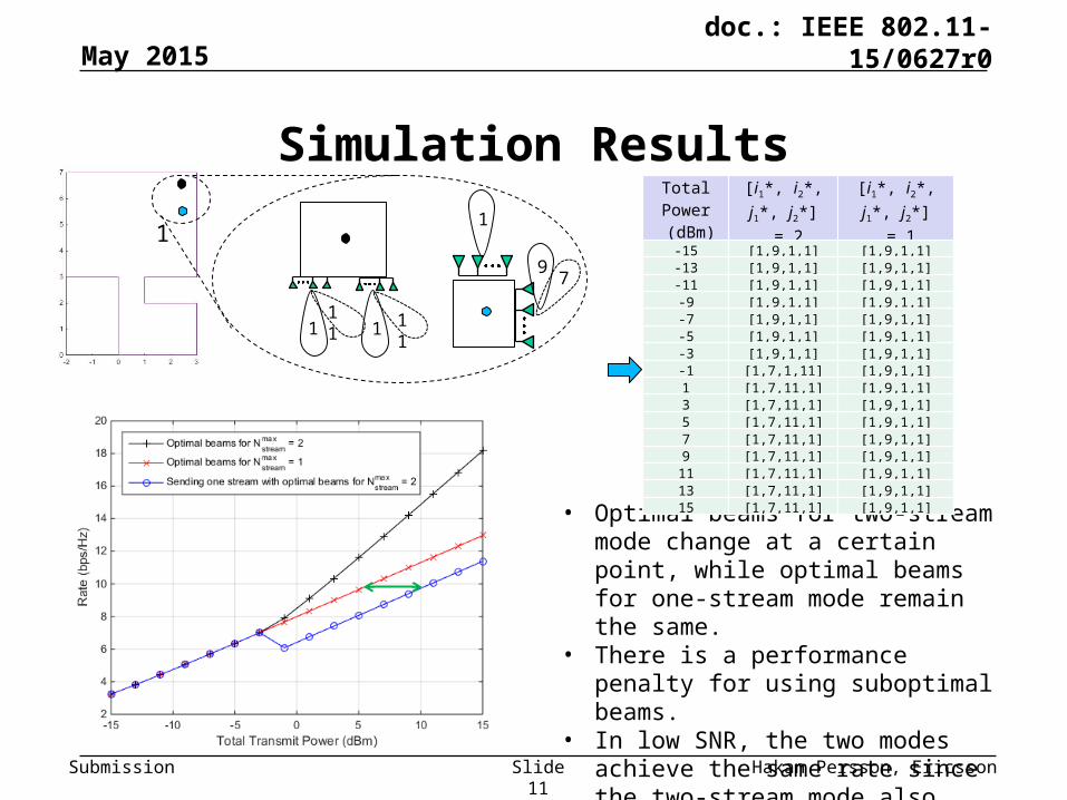
Simulation Results
Slide 11
May 2015
• Optimal beams for two-stream mode change at a certain point, while optimal beams for one-stream mode remain the same.
• There is a performance penalty for using suboptimal beams.
• In low SNR, the two modes achieve the same rate since the two-stream mode also chooses one stream operation by allocating all power to one of the eigenchannels.
• This time, due to poor spatial properties of the channel, both modes pick the same beams for all total transmit power values.
• In low SNR, the two modes achieve the same rate since the two-stream mode also chooses one stream operation by allocating all power to one of the eigenchannels.
5
Total Power (dBm)
[i1*, i2*, j1*, j2*] = 2
[i1*, i2*, j1*, j2*]= 1
-15 [14,8,4,4] [14,8,4,4]
-13 [14,8,4,4] [14,8,4,4]
-11 [14,8,4,4] [14,8,4,4]
-9 [14,8,4,4] [14,8,4,4]
-7 [14,8,4,4] [14,8,4,4]
-5 [14,8,4,4] [14,8,4,4]
-3 [14,8,4,4] [14,8,4,4]
-1 [14,8,4,4] [14,8,4,4]
1 [14,8,4,4] [14,8,4,4]
3 [14,8,4,4] [14,8,4,4]
5 [14,8,4,4] [14,8,4,4]
7 [14,8,4,4] [14,8,4,4]
9 [14,8,4,4] [14,8,4,4]
11 [14,8,4,4] [14,8,4,4]
13 [14,8,4,4] [14,8,4,4]
15 [14,8,4,4] [14,8,4,4]
Submission
doc.: IEEE 802.11-15/0627r0
Hakan Persson, Ericsson
Summary and Conclusions
Slide 14
May 2015
• We observe that optimal beams can be different according to MIMO mode, e.g., maximum number of streams.
• In some situations, it is useful for the transmitter to know the optimal beams for different MIMO modes.
• Hence, receiver may need to feed back multiple sets of beamforming indices (each for one MIMO mode).
• Further study may be required for the design of feedback in 11ay.