1 Senior Program Officer, National Cooperative Highway Research Program, TRB, Washington, DC SUMMARY OF NCHRP RESEARCH ON DEVELOPMENT OF A PRECAST BENT CAP SYSTEM FOR SEISMIC REGIONS Waseem Dekelbab 1 Abstract This paper summarizes the findings of the research conducted under NCHRP Project 12-74 to (1) develop and validate design methodologies; (2) recommend design and construction specifications; and (3) provide design examples and example connection details for precast bent cap systems using emulative and hybrid connections for integral and nonintegral systems for all seismic regions throughout the United States. Introduction Precast bent cap systems are of increasing utility in highway construction. Precasting eliminates on-site concrete forming, placement, and curing operations making bridge construction safer and more environmentally friendly. It also removes bent cap construction from the critical path, thus accelerating the construction process. Precasting also improves quality and durability because the work is performed in a controlled environment. These benefits of precast bent cap systems support the philosophy of "get in, get out, stay out." Successful use of precast bent caps relies on proper design, constructability, and performance of the connections. Early uses of precast bent caps were limited to applications where minimal moment and shear transfer were required at connections. In seismic regions, provisions normally must be made to transfer greater forces through connections and to ensure girder continuity in the longitudinal direction. Precast bent cap systems can be classified as either integral or nonintegral depending on superstructure-to-substructure connectivity. Integral bent cap systems develop longitudinal continuity through girder-to-bent cap connections. In contrast, nonintegral bent cap systems use bent cap-to-column connections to provide transverse moment continuity. However, integral precast bent cap systems require the use of precast cap-to-column and superstructure-to-cap connections. Additionally, precast connections are typically categorized as being either emulative or hybrid. Emulative connections are designed to produce a system performance that is similar to (or “emulates”) that achieved by traditional monolithic, cast-in-place (CIP) construction. Bridges using emulative precast bent cap connections are expected to form plastic hinges in the columns and redistribute forces to other members like CIP systems. The lateral force-displacement response of an emulative system is characterized by full hysteresis loops and stable energy dissipation. This 75
Transcript
1 Senior Program Officer, National Cooperative Highway Research Program, TRB, Washington, DC
SUMMARY OF NCHRP RESEARCH ON DEVELOPMENT OF A PRECAST BENT CAP SYSTEM FOR SEISMIC REGIONS
Waseem Dekelbab1
Abstract
This paper summarizes the findings of the research conducted under NCHRP Project 12-74 to (1) develop and validate design methodologies; (2) recommend design and construction specifications; and (3) provide design examples and example connection details for precast bent cap systems using emulative and hybrid connections for integral and nonintegral systems for all seismic regions throughout the United States. Introduction
Precast bent cap systems are of increasing utility in highway construction. Precasting eliminates on-site concrete forming, placement, and curing operations making bridge construction safer and more environmentally friendly. It also removes bent cap construction from the critical path, thus accelerating the construction process. Precasting also improves quality and durability because the work is performed in a controlled environment. These benefits of precast bent cap systems support the philosophy of "get in, get out, stay out." Successful use of precast bent caps relies on proper design, constructability, and performance of the connections. Early uses of precast bent caps were limited to applications where minimal moment and shear transfer were required at connections. In seismic regions, provisions normally must be made to transfer greater forces through connections and to ensure girder continuity in the longitudinal direction.
Precast bent cap systems can be classified as either integral or nonintegral depending on superstructure-to-substructure connectivity. Integral bent cap systems develop longitudinal continuity through girder-to-bent cap connections. In contrast, nonintegral bent cap systems use bent cap-to-column connections to provide transverse moment continuity. However, integral precast bent cap systems require the use of precast cap-to-column and superstructure-to-cap connections.
Additionally, precast connections are typically categorized as being either emulative or hybrid. Emulative connections are designed to produce a system performance that is similar to (or “emulates”) that achieved by traditional monolithic, cast-in-place (CIP) construction. Bridges using emulative precast bent cap connections are expected to form plastic hinges in the columns and redistribute forces to other members like CIP systems. The lateral force-displacement response of an emulative system is characterized by full hysteresis loops and stable energy dissipation. This
75
response results from considerable damage and potential residual deformations--the underlying assumption of seismic design philosophy for CIP bridges. Hybrid systems are designed to provide sufficient energy dissipation through controlled rocking about specially detailed joints at the column ends. In addition, hybrid systems provide a significant reduction in damage and residual offsets as compared to cast-in-place and emulative systems.
NCHRP Project 12-74 was conducted to (1) develop and validate design methodologies, (2) recommend design and construction specifications, and (3) provide design examples and example connection details for precast bent cap systems using emulative and hybrid connections for integral and nonintegral systems for all seismic regions throughout the United States.
In this paper, the research efforts conducted under this NCHRP project related to nonintegral systems are summarized. The efforts summarized herein are: (1) experimental test program; (2) testing protocol and instrumentation; and (3) test results and key findings, extracted from the project’s final report authored by the principal investigator Dr. Jose I. Restrepo, professor at University of California, San Diego (UCSD); and the co-principal investigator Dr. Eric E. Matsumoto, professor at California State University, Sacramento (CSUS).
Experimental Test Program In this research program, a number of promising precast bent cap details were investigated though experimental testing. These specimens were developed to meet a variety of performance objectives for locations throughout the nation’s seismic regions; descriptions are provided in Table 1.
Table 1 Summary of Experimental Specimens
Code Specimen Name
Specimen Type Specimen Purpose
CIP Cast-in-place control
specimen
Beam-to-column emulative
Control specimen detailed in accordance with Recommended AASHTO LRFD Seismic Guide Specification for high seismic applications.
GD Grouted duct specimen
Beam-to-column emulative
Grouted duct specimen designed to provide high ductility response with similar response as CIP specimen
76
Code Specimen
Name Specimen Type Specimen Purpose
CPFD Cap pocket full ductility specimen
Beam-to-column emulative
Cap pocket specimen designed to provide high ductility response with similar response as CIP specimen. Detail uses a corrugated metal pipe to provide stay-in-place form and joint shear reinforcement
CPLD Cap pocket limited ductility
specimen
Beam-to-column emulative
Cap pocket specimen design with alleviated seismic detailing intended to provide limited ductility for regions of low to moderate seismicity. Detail uses similar corrugated metal pipe detail as CPFD.
Hybrid 1 Conventional hybrid
specimen
Beam-to-column hybrid
Hybrid specimen detailed with conventional spiral confinement reinforcement and full length mild reinforcement. Detail is intended to be a hybrid detail most similar to traditional CIP construction.
Hybrid 2 Concrete filled pipe hybrid specimen
Beam-to-column hybrid
Hybrid specimen using full length steel shell acting as confinement and shear reinforcement. Mild reinforcement utilized only at joint to provide energy dissipation and terminated into the column.
Hybrid 3 Dual steel shell hybrid
specimen
Beam-to-column hybrid
Hybrid specimen using two full length shells (outer steel and inner corrugated metal pipe) acting as confinement and shear reinforcement. Mild reinforcement utilized only at joint. Dual shell detail intended to reduce weight of column section for precasting.
77
Testing Protocol and Instrumentation In the following sections, the test setup, loading, and instrumentations for nonintegral emulative and hybrid specimens will be summarized. Emulative Specimens The specimen test setup, shown in Figure 1, included a simply supported bent cap with a column stub that allowed biaxial loading and accurate establishment of specimen forces. The specimen was tested in inverted position. Loads were applied using a vertical hydraulic actuator to apply scaled gravity load and the horizontal hydraulic actuator to induce seismic response. The test setup ensured accurate conditions at each end of the joint so that the force transfer mechanism in the joint could be investigated. Different axial force conditions in the bent cap were produced for the push and pull directions. Force controlled and displacement controlled loadings were applied to all specimens. The force controlled loading was used for an approximate determination of first yield of column longitudinal bars in the push and pull directions, establishment of effective yield, and application of the displacement controlled sequence including quasi-static displacement in 3 cycles. Nominal displacement ductility (µ) demand, as multiples of system effective yield displacement, was applied at the µ1, µ1.5, µ2, µ3, µ4, µ6, µ8, and µ10 levels, or until the residual capacity of the specimen dropped below 30% of the maximum load. External gages, including linear and string potentiometers and Linear Variable Differential Transformers (LVDT) were mounted on the column, joint, and bent cap. Internal strain gages were placed on bent cap, joint, and column reinforcing bars, as well as corrugated ducts or pipe. In addition to the approximately 100 sets of data, specimen response was also monitored using digital photos, crack markings and measurements, video recording, and notes. Hybrid Specimens The test setup for the hybrid specimens, shown in Figure 2, is similar to that used for the emulative specimens. The specimens were constructed in the upright condition and then inverted for installation in the test setup. The vertical actuator was set to apply a constant load during testing to simulate gravity loading. This force varied between hybrid specimens in order to match the lateral response of the three hybrid tests. The horizontal actuator was actively controlled to apply specified forces or displacements during testing. The initial stage of loading consisted of force-controlled loading protocols in which positive and negative lateral forces of increasing magnitude were applied until first yield of the extreme mild reinforcing bar was reached. Each force loading cycle was repeated three times in both directions. Following the first yield of the system, the lateral
78
loading was applied to a specified lateral drift ratio. At each cycle to a given drift ratio, the column was subjected to two cycles in both directions followed by one cycle to the previous lateral drift. This protocol was developed to help accuratelymodels of the system. External instrumentation mounted on the specimens consisted of linear potentiometers and inclinometers deformation in the member. In addition, a significant were employed to capture the local response of materials.
Figure 1 Test Setup for Emulative Specimens
loading was applied to a specified lateral drift ratio. At each cycle to a given drift ratio, the column was subjected to two cycles in both directions followed by one cycle to the previous lateral drift. This protocol was developed to help accurately calibrate non
External instrumentation mounted on the specimens consisted of linear potentiometers and inclinometers for measuring and isolating various modes of deformation in the member. In addition, a significant number of internal strain gages were employed to capture the local response of materials.
Figure 1 Test Setup for Emulative Specimens
loading was applied to a specified lateral drift ratio. At each cycle to a given drift ratio, the column was subjected to two cycles in both directions followed by one cycle to the
calibrate non-linear
External instrumentation mounted on the specimens consisted of linear measuring and isolating various modes of
of internal strain gages
79
Figure 2 Test Setup for Hybrid Specimens
Test Results and Key Finding
This section summarizesand hybrid experimental tests. In reporting specimen response, displacement ductility, and drift ratio are both used. Drift ratio is defined as the column displacement divided by the column height, and is reported as a pcomparison of specimen response than displacement ductility. However, system ductility levels are also reported, although these values should be considered nominal (i.e., approximate) due to the approximatedrift ratio are used interchangeably. Non-integral Emulative Connections This section summarizes specimens: Cast-in-Place (CIP), Grouted Duct (GD), Cap and Cap Pocket Limited Ductility (CPLD). The joint response is summarized in Tables 2 and 3. Comparisons are made between the CIP and precast connections, as well as between the full and limited ductility specimens. limited and joint behavior compared very favorably with contrast, the joint region for the CPLD specimen exhibited a significant level of distress that increased throughout the test.envelopes, and Figure 4 shows the loadfigures reveal a very similar overall CPLD and CIP specimens. The dominance of ductile plastic hinging in the column and
Figure 2 Test Setup for Hybrid Specimens
Findings
This section summarizes the key aspects of specimen response for the emulativehybrid experimental tests. In reporting specimen response, displacement ductility,
and drift ratio are both used. Drift ratio is defined as the column displacement divided by is reported as a percent. It provides a more consistent basis for
comparison of specimen response than displacement ductility. However, system ductility levels are also reported, although these values should be considered nominal (i.e., approximate) due to the approximate determination of first yield. The terms drift and drift ratio are used interchangeably.
integral Emulative Connections
This section summarizes the primary aspects of specimen response for all Place (CIP), Grouted Duct (GD), Cap Pocket Full Ductility (CPFD),
and Cap Pocket Limited Ductility (CPLD). The joint response is summarized in Tables 2 Comparisons are made between the CIP and precast connections, as well as
between the full and limited ductility specimens. GD as well as CPFD joint distress was limited and joint behavior compared very favorably with that of the CIP specimen
he joint region for the CPLD specimen exhibited a significant level of distress that increased throughout the test. Figure 3 shows the joint shear stress-strain response
Figure 4 shows the load-displacement envelopes for all specimens. overall load-displacement response for the GD, CPFD,
and CIP specimens. The dominance of ductile plastic hinging in the column and
imen response for the emulative hybrid experimental tests. In reporting specimen response, displacement ductility, µ,
and drift ratio are both used. Drift ratio is defined as the column displacement divided by a more consistent basis for
comparison of specimen response than displacement ductility. However, system ductility levels are also reported, although these values should be considered nominal (i.e.,
determination of first yield. The terms drift and
for all Pocket Full Ductility (CPFD),
and Cap Pocket Limited Ductility (CPLD). The joint response is summarized in Tables 2 Comparisons are made between the CIP and precast connections, as well as
joint distress was the CIP specimen. In
he joint region for the CPLD specimen exhibited a significant level of distress ain response
displacement envelopes for all specimens. The , CPFD,
and CIP specimens. The dominance of ductile plastic hinging in the column and
80
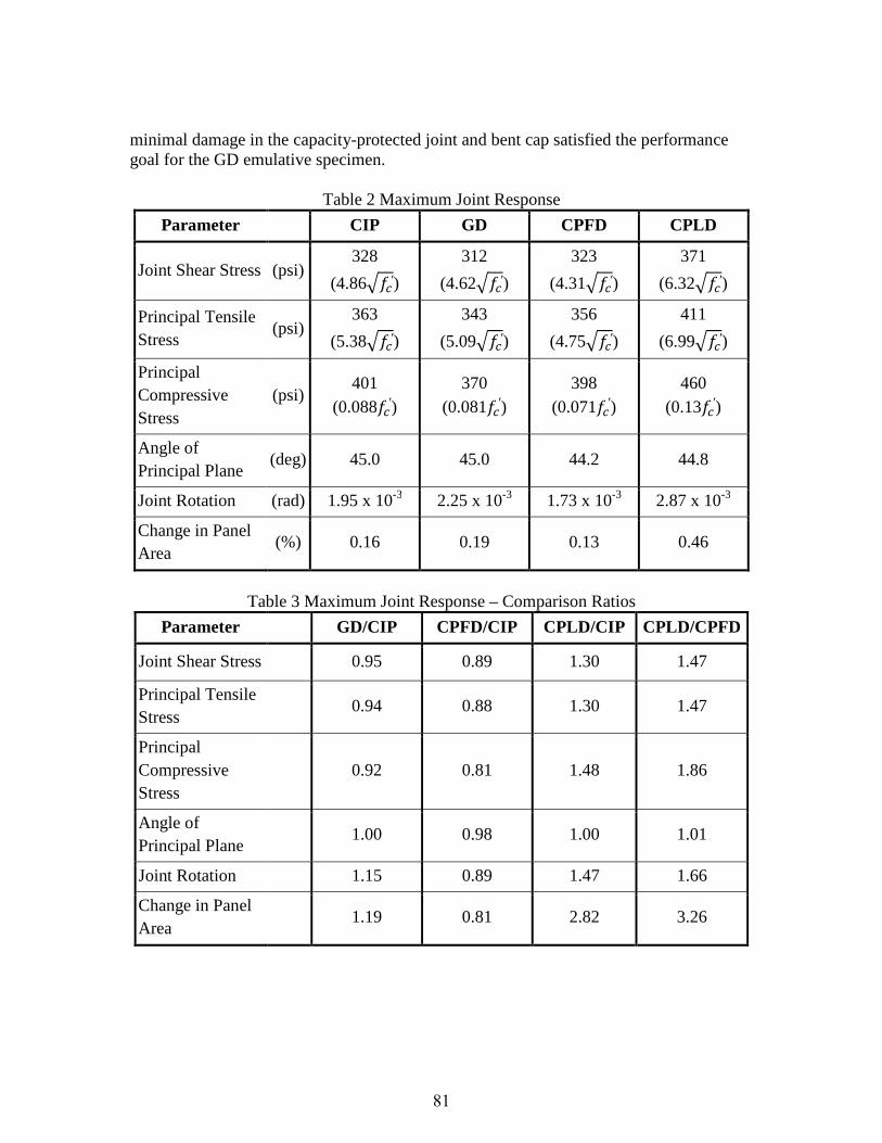
minimal damage in the capacity-protected joint and bent cap satisfied the performance goal for the GD emulative specimen.
Table 2 Maximum Joint Response
Parameter CIP GD CPFD CPLD
Joint Shear Stress (psi) 328
(4.86���′)
312
(4.62���′)
323
(4.31���′)
371
(6.32���′)
Principal Tensile Stress
(psi) 363
(5.38���′)
343
(5.09���′)
356
(4.75���′)
411
(6.99���′)
Principal Compressive Stress
(psi) 401
(0.088��′) 370
(0.081��′) 398
(0.071��′) 460
(0.13��′)
Angle of Principal Plane
(deg) 45.0 45.0 44.2 44.8
Joint Rotation (rad) 1.95 x 10⁻³ 2.25 x 10⁻³ 1.73 x 10⁻³ 2.87 x 10⁻³
Change in Panel Area
(%) 0.16 0.19 0.13 0.46
Table 3 Maximum Joint Response – Comparison Ratios
Parameter GD/CIP CPFD/CIP CPLD/CIP CPLD/CPFD
Joint Shear Stress 0.95 0.89 1.30 1.47
Principal Tensile Stress
0.94 0.88 1.30 1.47
Principal Compressive Stress
0.92 0.81 1.48 1.86
Angle of Principal Plane
1.00 0.98 1.00 1.01
Joint Rotation 1.15 0.89 1.47 1.66
Change in Panel Area
1.19 0.81 2.82 3.26
81
Figure 3 Joint Shear Stress vs. Joint Shear Strain Envelopes
Figure 4 Applied Lateral Force vs. Lateral Displacement Envelopes
Non-integral Hybrid Connections This section summarizes the primary aspects of specimen response including column hysteretic response (lateral force-displacement), joint response, and residual drift. Comparisons are made between the CIP and hybrid connections (Hybrid 1—conventional hybrid specimen, Hybrid 2—concrete filled pipe hybrid specimen, and Hybrid 3—dual steel shell hybrid specimen). The force-displacement envelopes for all three hybrid specimens along with the cast-in-place specimen are shown in Figure 5. It is apparent that all hybrid specimens have greater lateral capacity than the cast-in-place control. The higher lateral capacity resulted from the larger than anticipated effective post-tensioning force in the conventional specimen and that the other hybrid specimens were designed to be similar to the conventional hybrid specimen. Regarding joint response, only minor damage occurred within the joint during the entire testing of all hybrid specimens. Diagonal cracking patterns were observed indicating joint shear cracking, but the joint reinforcement was adequate to resist extensive crack growth and subsequent joint damage. One of the major aims of hybrid bridge systems is the reduction of residual displacements. Figure 6 shows the ratio of recorded residual drift to the maximum drift during the first cycle for the three hybrid and the cast-in-place control specimens. However, the second cycle exhibited slightly greater residual drifts. In general, for the conventional hybrid specimen the residual drift ratio increases with the applied lateral drift. However, the recorded residual drift was significantly less than for the cast-in-place specimen indicating an expected improved post-earthquake performance.
83
Figure 5 Lateral Force vs. Lateral Displacement Envelopes for Hybrid Connections
Figure 6 Residual Drift Ratio vs. Applied Drift Ratio for Hybrid Connections
Displacement, inches
Drift Ratio, %
Late
ral Fo
rce
, kip
s
0 0.5 1 1.5 2 2.5 3 3.5 4 4.5 5
0 0.8 1.6 2.4 3.2 4 4.8 5.6 6.4 7.2 8
0
20
40
60
80
100
Hybrid 1
Hybrid 2
Hybrid 3
Cast-in-place
Drift Ratio, %
Re
sid
ua
l /
Ma
xim
um
Dri
ft,
%
1 2 3 4 5 6
0
20
40
60
80
100
1.0% Residual Drift Ratio
1.5% Residual Drift Ratio
2.0% RDR
Hybrid 1
Hybrid 2
Hybrid 3
Cast-in-place
84
Key Findings
Based on a review of the experimental efforts conducted under NCHRP 12-74, the research team provided the following key findings:
• The current joint shear design methodology contained in the 2009 LRFD Seismic Guide Specification, with minor modifications, is appropriate for the design of emulative and hybrid, integral and nonintegral precast bent cap systems.
• For Seismic Design Categories (SDCs) B, C and D, the level of joint shear reinforcement should be based on the calculated principal tensile stress, and if the stress
exceeds 0.11���′, ksi, joint shear reinforcement should be specifically designed. • Minimum joint shear reinforcement should be provided for all SDCs. • Design methodologies and detailing for hybrid systems should be employed to
facilitate the implementation of these systems for improving the post-earthquake functionality of the bridge structure.
• Properly designed and detailed hybrid systems can produce substantially less residual deformation and damage than cast-in-place and emulative systems.
• In hybrid systems, the contribution of flexural reinforcement should be limited to produce its intended response. In addition, the neutral axis depth should be limited to minimize the magnitude of compressive strains within the section.
• Design and detailing of the unbonded post-tensioning and longitudinal reinforcement in a hybrid system should be such as to ensure premature fracture does not occur.
• Provisions of the 2009 LRFD Seismic Guide Specification for the design of multi-column integral connections should be updated for consistency with the design of multi-column nonintegral connections.
• For the cap pocket connections, the use of a supplementary hoop at the top and bottom of the corrugated pipe should be employed.
• Proposed equations for anchorage of reinforcement within grouted ducts and the cap pocket connection should be implemented.
• Future provisions of seismic design and detailing requirements should be developed for knee joints for both cast-in-place and precast bent caps.
• Alternate connection details are provided for structures located in SDC A with SD1 less than 0.10. However, minimum vertical stirrups in the joint are recommended, as well as the extension of column longitudinal reinforcement as close as practical to the top of the bent cap.
• Grouted joints for use in seismic applications should be limited to 3 inches in thickness and should be reinforced with hoops to maintain the spacing of lateral reinforcement within the plastic hinge region.
• For hybrid columns and integral closure joints, grouted connections should employ a 3 pound per cubic yard fraction of polypropylene fibers to enhance the integrity of the joint.
85
Conclusions
In addition to the contractors’ final report that will be published as NCHRP Report 681, Development of A Precast Bent Cap System for Seismic Regions, a series of recommended updates to the AASHTO LRFD Bridge Design Specifications, Guide Specification for LRFD Seismic Bridge Design and Bridge Construction Specifications were developed. Design specifications SDCs C and D, SDC B, and SDC A were developed in appropriate format for incorporation into a future edition of the AASHTO Guide Specifications for LRFD Seismic Bridge Design (LRFD SGS). A major proposed change is to revise Article 8.13—Joint Design for SDCs C and D of the 2009 LRFD SGS to include precast bent cap connections (grouted duct and cap pocket). Also, to address all seismic design categories, two new articles were required and recommended to be added: an article on Joint Design for SDC A and an article on Joint Design for SDC B. Design flow charts and design examples were developed to illustrate the use of design specifications for both grouted duct and cap pocket connections at all SDC levels. Construction specifications, Special Requirements for Precast Bent Cap Connections, were provided and proposed for inclusion in the AASHTO LRFD Bridge Construction Specifications (LRFD BCS). Acknowledgements
The work summarized herein was performed under NCHRP Project 12-74 and was guided by NCHRP Project Panel C12-74, chaired by Mr. Richard A. Pratt, with members Dr. Xiaohua Hannah Cheng, Mr. Carl J. Fuselier, Mr. Jim Ma, Mr. Richard Marchione, Mr. Chuck Prussack, Ms. Holly Winston, and Mr. Lloyd M. Wolf. Mr. Derrell A. Manceaux and Mr. Stephen F. Maher provided liaison with the FHWA and TRB, respectively. Dr. Waseem Dekelbab served as the responsible NCHRP staff officer. The final report was prepared by the principal investigator Dr. Jose I. Restrepo, professor of structural engineering at the University of California, San Diego (UCSD), and the co-principal investigator Dr. Eric E. Matsumoto, Professor at California State University, Sacramento (CSUS). The other author of this report is Dr. Matthew J. Tobolski, President of Tobolski Watkins Engineering, Inc. and former graduate researcher at UCSD.


![SUMMARY CHANGES FOR NCHRP REPORT 350 GUIDELINESsp.design.transportation.org/Documents/BenBuchan...SUMMARY CHANGES FOR NCHRP REPORT 350 GUIDELINES [NCHRP 22-14 (02)] Keith A. Cota,](https://static.documents.pub/doc/80x56/5e961a4e0d29da5fdc2cb462/summary-changes-for-nchrp-report-350-summary-changes-for-nchrp-report-350-guidelines.jpg)


