Research Signpost 37/661 (2), Fort P.O., Trivandrum-695 023, Kerala, India Advanced Technologies for High-Speed Optical Communications, 2007: 247-277 ISBN: 81-308-0171-X Editor: Lei Xu 9 Suppression of intrachannel nonlinearities in high-speed WDM systems Ivan B. Djordjevic University of Arizona, Department of Electrical and Computer Eng., Tucson AZ 85721, USA Abstract High-speed optical transmission systems operating at 40 Gb/s or higher are severely limited by intrachannel nonlinearities such as intrachannel four- wave mixing (IFWM) and intrachannel cross-phase modulation (IXPM). The electrical approaches to deal with intrachannel nonlinearities may be classified into three broad categories: modulation formats, constrained (or line) coding, and equalization techniques. The IFWM is a phase-sensitive effect, and the aim of the first approach is to remove the phase short-term coherence of the pulses emitted in a given neighborhood. The role of constrained coding is to avoid those waveforms in the Correspondence/Reprint request: Dr. Ivan B. Djordjevic, University of Arizona, Department of Electrical and Computer Eng., Tucson, AZ 85721, USA. E-mail: [email protected];
Transcript
Research Signpost 37/661 (2), Fort P.O., Trivandrum-695 023, Kerala, India
Advanced Technologies for High-Speed Optical Communications, 2007: 247-277 ISBN: 81-308-0171-X Editor: Lei Xu
9 Suppression of intrachannel nonlinearities in high-speed WDM systems
Ivan B. Djordjevic
University of Arizona, Department of Electrical and Computer Eng., Tucson AZ 85721, USA
Abstract High-speed optical transmission systems operating at 40 Gb/s or higher are severely limited by intrachannel nonlinearities such as intrachannel four-wave mixing (IFWM) and intrachannel cross-phase modulation (IXPM). The electrical approaches to deal with intrachannel nonlinearities may be classified into three broad categories: modulation formats, constrained (or line) coding, and equalization techniques. The IFWM is a phase-sensitive effect, and the aim of the first approach is to remove the phase short-term coherence of the pulses emitted in a given neighborhood. The role of constrained coding is to avoid those waveforms in the
Correspondence/Reprint request: Dr. Ivan B. Djordjevic, University of Arizona, Department of Electrical and Computer Eng., Tucson, AZ 85721, USA. E-mail: [email protected];
Ivan B. Djordjevic 248
transmitted signal that are most likely to be received incorrectly. In this chapter we describe three alternative techniques for suppression of intrachannel nolinearities: (i) constrained coding techniques, (ii) combined nonlinear ISI cancellation and error control, and (iii) advanced modulation techniques. Three different constrained coding techniques will be presented: (a) the use of constrained encoding itself, (b) combined constrained and error control coding and (c) deliberate error insertion. The nonlinear ISI cancellation scheme employs the maximum a posteriori probability (MAP) symbol decoding based on Bahl-Cocke-Jelinek-Raviv (BCJR) algorithm, while the forward error correction is based on low-density parity-check (LDPC) codes. The nonlinear ISI channel is modeled by a finite state machine (FSM) whose transition and output functions describe the dependency of the channel statistics and the ISI on transmitted patterns. The BCJR algorithm operates on a trellis of the corresponding FSM, and creates the soft information (detected bit likelihoods) used in the iterative decoder. To improve the BER performance of nonlinear BCJR equalizer further, a noise-predictive BCJR equalizer is introduced. In addition we present an efficient method for testing the efficiency of modulation techniques for countering the effects of IFWM by calculating the sum of all the contributors at a given resonance position. We employ this method to develop a modulation technique that shows a significant Q-factor improvement of up to 7.5dB (depending on the number of spans and the phase sequence implemented) over the uncoded RZ-OOK. The main feature of these schemes is that they can operate in the regime of very strong intrachannel nonlinearities where FEC schemes such as turbo or LDPC codes are not designed to operate. 1. Introduction High-speed optical transmission systems operating at 40 Gb/s or higher are severely limited by intrachannel nonlinearities such as intrachannel four-wave mixing (IFWM) and intrachannel cross-phase modulation (IXPM) [1]-[5]. Different electrical approaches to deal with intrachannel nonlinearities may be classified into three broad categories: (i) modulation formats [2]-[3], (ii) constrained (or line) coding [1], and (iii) equalization techniques. The IFWM is a phase-sensitive effect, and the aim of the first approach is to remove the phase short-term coherence of the pulses emitted in a given neighborhood. The role of constrained coding [1] is to avoid those waveforms in the transmitted signal that are most likely to be received incorrectly. This approach has been carefully examined by the author, and significant performance improvement has been demonstrated for various constrained codes and dispersion maps [1]. Previous work in nonlinear intersymbol interference (ISI) reduction at lower bit rates has involved the use of equalization [7] and nonlinear cancellation [8]. A drawback of linear equalizers is that they cannot handle non-linear effects,
Suppression of intrachannel nonlinearities in high-speed WDM systems 249
while the nonlinear cancellation technique in [8] does not take into account the effect of post-cursor ISI. The Volterra series nonlinear equalization technique used to improve performance in a duobinary modulation scheme [9] may suffer from error propagation due to the nonlinear feedback. Other techniques proposed recently in context of polarization mode dispersion (PMD) compensation and chromatic dispersion (CD) compensation include maximum likelihood sequence detection (MLSD) based on Viterbi algorithm [10]-[11]. The disadvantage of the Viterbi algorithm is that it does not produce the soft information required for iterative decoding. To deal with linear ISI the turbo equalization technique was proposed in [12] in a context of a wireless multipath channel. The turbo equalization scheme from [12] employs a convolutional code of rate ½, which is unacceptably low for high-speed optical transmission. Similar turbo-equalization schemes have been extensively studied for a variety of applications such as wireless communications [13] and magnetic recording [14]. This chapter is based on our several recent publications [1],[15],[16],[36]. We describe three alternative approaches to suppress the intrachannel fiber nonlinearities: (i) suppression of intrachannel nonlinearities using constrained coding, (ii) suppression of intrachannel nonlinearities using combined nonlinear ISI cancellation and error control, and (iii) suppression of intrachannel nonlinearities using advanced modulation formats. Three different constrained coding approaches for suppression of intrachannel nonlinearities are discussed: (1) the use of constrained encoding itself, (2) combined constrained and error control coding, and (3) deliberate error insertion. The constrained encoding itself is based on the following three principles: (a) the most troublesome sequences are identified and forbidden, (b) the zero-symbol in so called “resonant positions” is converted into one-symbol, and (c) the different contributions to a ghost pulse creation cancel each other in resonant positions. Even though the constrained decoding is conceptually simple (it is based on sliding-window decoder [17]-[18]), it decouples the channel and the error correction decoder, because it operates on hard bits and does not produce soft information, which is necessary for iterative (LDPC/turbo) decoding. An alternative scheme that circumvents the above problem is known as reverse concatenation [19], and it has been recently adapted for soft detectors [20]. In this scheme, the Bahl, Cocke, Jelinek and Raviv (BCJR) algorithm [21] is performed on a trellis corresponding to the constrained graph. The combined constrained and error control coding can operate in the presence of strong intrachannel nonlinearities when even advanced forward error correction (FEC) schemes would be overwhelmed with errors. The motivation for the deliberate error insertion technique [22] is the fact that design of a good high rate constrained code is a challenging problem when the desired constraint is complicated because the encoder and decoder might be unacceptably complex
Ivan B. Djordjevic 250
for high-speed applications, and large decoding window size may result into unacceptable error propagation. The number of error caused by error propagation due to increased decoding window size may result in exceeding error correction capability of the FEC code employed in the standard concatenation scheme. Even though combined constrained and error correction scheme provides an excellent coding gain, it requires using encoders and decoders of relatively high complexity. The idea is to trade the redundancy introduced by a constrained code for stronger FEC codes. In other words, only a FEC code is used, while the constraint is imposed on the coded sequence by deliberate error insertion. The LDPC code is designed to be strong enough to correct both channel errors and errors introduced by the constraint monitoring circuit. The second approach to deal with intrachannel nonlinearities is, as mentioned above, the concept of combined nonlinear ISI cancellation and error control coding introduced by author in [15]. The nonlinear ISI cancellation scheme employs the maximum a posteriori probability (MAP) symbol decoding based on BCJR algorithm, while the forward error correction is based on girth-6 [23]-[25] and girth-8 low-density parity-check (LDPC) codes [25]. The nonlinear ISI channel is modeled by a finite state machine (FSM) whose transition and output functions describe the dependency of the channel statistics and the ISI on transmitted patterns. The BCJR algorithm operates on a trellis of the corresponding FSM, and creates the soft information (detected bit likelihoods) used in the iterative decoder. To improve the BER performance of nonlinear BCJR equalizer further, or equivalently to reduce the BCJR detector complexity, a noise-predictive BCJR (NP-BCJR) equalizer is described [16]. The noise-predictive filter, implemented as finite-impulse response (FIR) filter, estimates the colored noise, which is removed from the sampled signal after the photodetection and electrical filtering and passed to the second nonlinear equalizer ingredient-the BCJR equalizer. The BCJR equalizer removes the intrachannel nonlinearities and requires reduced number of states in trellis compared to the case where no noise-predictive filter is being employed. In addition we present an efficient method for suppression of IFWM by choosing the initial pulse phases in such a way to minimize the effect of different ghost-pulse contributors at the zero-bit position being in “resonance” instead of canceling them, without reducing the code rate [36]. We define the new figure of merit for assessing the influence of IFWM, and use it to select a better modulation format among several ones depending on information content. The main feature of the proposed schemes is that they can operate in the regime of very strong intrachannel nonlinearities where FEC schemes such as turbo or LDPC codes are not designed to operate. Most of dispersion maps
Suppression of intrachannel nonlinearities in high-speed WDM systems 251
used in 10 Gb/s systems will suffer from strong intrachannel nonlinearities if used for 40 Gb/s transmission without any modifications. The proposed schemes are, therefore, excellent candidates for a 40 Gb/s upgrade over existing 10 Gb/s infrastructure. Moreover, the proposed schemes require only the modifications on transmitter and receiver sides of a transmission system. To investigate the bit-error rate (BER) degradation due to nonlinear ISI at high bit rates, and quantify gains that can be obtained using the proposed methods, we have developed an advanced simulator that takes into account the effects of the optical and electrical components employed in the system. The chapter is organized as follows. The intrachannel nonlinear effects are briefly introduced in Section 2. Different constrained coding techniques are described in Section 3. The nonlinear BCJR equalization principle is described in Section 4, while noise-predictive BCJR equalization principle is described in Section 5. The novel modulation technique to suppress IFWM is introduced in Section 6. Some important conclusions are given in Section 7. 2. Intrachannel nonlinearities The signal propagation through the transmission medium is modeled by the generalized nonlinear Schrödinger equation (GNLSE) [1],[35].
22 323
2 2 32 2 6 R
AA i A AA i A T Az T T T
α ββ γ⎛ ⎞∂∂ ∂ ∂
= − − + + −⎜ ⎟⎜ ⎟∂ ∂ ∂ ∂⎝ ⎠A,
(1)
where z is the propagation distance along the fiber, relative time gvztT /−= gives a frame of reference moving at the group velocity vg, A(z,T) is the complex field amplitude of the pulse, α is the attenuation coefficient of the fiber, β2 is the group velocity dispersion (GVD) coefficient, β3 is the second-order GVD, γ is the nonlinearity coefficient giving rise to Kerr effect nonlinearities: self-phase modulation (SPM), cross-phase modulation (XPM) and four-wave mixing (FWM) and TR is the Raman coefficient describing the stimulated Raman scattering (SRS). To study the interactions among the pulses within the channel, the field of a single channel can be decomposed as a sum of fields of individual pulses
1
,L
ll
A A=
= ∑
where Al represents the lth pulse (out of L) centered at t=tl. GNLSE can be rewritten, after the substitution, as
2 3*3
2 2 31 , , 1.
2 2 6
L Ll l lml l k
l l k m
A A AiA i A A Az T T
α ββ γ= =
⎛ ⎞∂ ∂ ∂⎜ ⎟+ + − =∑ ∑⎜ ⎟∂ ∂ ∂⎝ ⎠
(2)
Ivan B. Djordjevic 252
(SRS term was ignored to keep the explanation simpler.) The intrachannel nonlinearities may be identified as follows. The case l=k=m corresponds to SPM, the case l≠k≠m or l=k≠m to IFWM, and the case l=m≠k or k=m≠l to IXPM. In dispersion managed systems pulses undergo periodical widening and compression as they travel during transmission. The strongest interaction is at the point at which the pulses partially overlap, and in order to keep the IXPM low in pseudo-linear transmission, the pulses are allowed to spread over many bit-periods. However, in the pseudo-linear regime the second intrachannel nonlinear effect-IFWM is also present [1-5]. Dispersed pulses experiencing the nonlinearity see a portion of their filed shifted by a discrete frequency value due to FWM of spectral components within the same wavelength channel. At sufficiently high dispersion the frequency shift is translated into a discrete time shift located near the middle of a neighboring pulse. This energy transfer among the pulses within the same wavelength channel results in amplitude jitter if energy is transferred to a non-empty bit-slot or in ghost pulse creation if the energy is transferred to an empty bit-slot, as illustrated in Fig. 1 (a). The pulses at positions k, l and m, according to Eq. 2 may create a ghost pulse in an empty bit-slot located at m+k-l position (“the resonant condition”). The cumulative effect of the ghost pulse phenomenon is illustrated in Fig. 1(b), in which ghost pulse effect on transmitting a sequence “10011111” is shown. Triples of pulses at positions (3,-1,2), (4,-1,3), (5,-1,4), (6,-1,5) are all in resonance. Thus, in the resulting energy transfer to pulse position 0, the pulse at position “–1” loses a large amount of energy since it is involved in four triples. Figure 1(b) shows an ideal case in the sense that no other pulses take part in triples, and that effects of other nonlinearities are not shown.
(a) (b)
Figure 1. Ghost pulse phenomena: (a) pulses at positions 2, 3 and -1 give rise to a ghost pulse at position 0; (b) cumulative effect of ghost-pulse interaction. 3. Constrained coding approaches in supression of intrachannel nonlinearities 3.1 Constrained coding The role of a constrained code, as already mentioned in Introduction, is to impose certain constraints on a transmitted sequence in order to avoid those
Suppression of intrachannel nonlinearities in high-speed WDM systems 253
waveforms that are most likely to be incorrectly received. A constrained encoder translates an arbitrary user bit stream into a bit stream that satisfies the constraints of the channel. Three different constrained approaches successful in suppression of intrachannel nonlinearities are described in the reminder of the section. Constraint A Recently we identified the resonant sequences [1] like “1101”, “1011” and “11011” as the most troublesome. The directed graph of the constrained system avoiding those sequences is shown in Fig. 2. Valid sequences can be obtained by reading off the edge labels while making transitions from one state to another according to orientation of the edges. The largest code rate permitted by this constraint (capacity) is 0.6942. Since the most troublesome sequences are identified and forbidden, this constraint will result in excellent Q-factor improvement; however, the code rate is unacceptably low for high-speed transmission.
S3100 S2S1S0
1
0
S3100 S2S1S0
1
0
Figure 2. Directed graph a constraint avoiding the resonance patterns “1101”, “1011” and “11011”. Constraint B Consider a sequence of length L, cici+1…ci+L-1, satisfying the following constraint: if for k, l, m ∈ [i,i+L) and k+l-m ∈ [i,i+L), (k and l not necessarily distinct), ck = cl = cm = 1 then ck+l-m ≠ 0. If the above sequence is transmitted, then no ghost pulse will be created at any position (positions {0,1,…,L-1}). However, the amplitude jitter may be caused through the IFWM process described by Eq. 2. For L=4 the constraint has the capacity (the largest possible code rate) of 0.8791, and may be described by a directed graph in Fig. 3.
S31
10 S2S1S0
0
0
S31
10 S2S1S0
0
0
Figure 3. Directed graph of (0,2) RLL constraint (the number of successive ones is constrained between 0 and 2).
Ivan B. Djordjevic 254
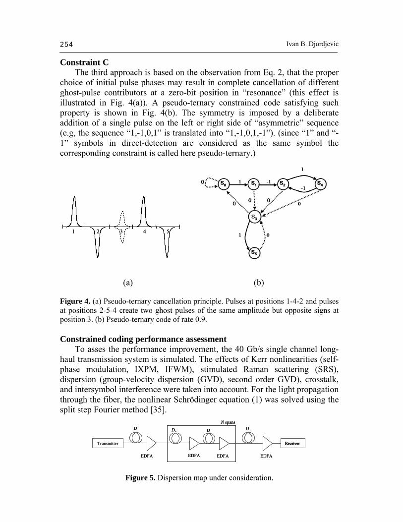
Constraint C The third approach is based on the observation from Eq. 2, that the proper choice of initial pulse phases may result in complete cancellation of different ghost-pulse contributors at a zero-bit position in “resonance” (this effect is illustrated in Fig. 4(a)). A pseudo-ternary constrained code satisfying such property is shown in Fig. 4(b). The symmetry is imposed by a deliberate addition of a single pulse on the left or right side of “asymmetric” sequence (e.g, the sequence “1,-1,0,1” is translated into “1,-1,0,1,-1”). (since “1” and “-1” symbols in direct-detection are considered as the same symbol the corresponding constraint is called here pseudo-ternary.)
1 2 3 4 51 2 3 4 5
(a) (b) Figure 4. (a) Pseudo-ternary cancellation principle. Pulses at positions 1-4-2 and pulses at positions 2-5-4 create two ghost pulses of the same amplitude but opposite signs at position 3. (b) Pseudo-ternary code of rate 0.9. Constrained coding performance assessment To asses the performance improvement, the 40 Gb/s single channel long-haul transmission system is simulated. The effects of Kerr nonlinearities (self-phase modulation, IXPM, IFWM), stimulated Raman scattering (SRS), dispersion (group-velocity dispersion (GVD), second order GVD), crosstalk, and intersymbol interference were taken into account. For the light propagation through the fiber, the nonlinear Schrödinger equation (1) was solved using the split step Fourier method [35].
Transmitter Receiver
N spans
EDFA
D+ D-D- D+
EDFAEDFA EDFA
Transmitter Receiver
N spans
EDFA
D+ D-D- D+
EDFAEDFA EDFA
Figure 5. Dispersion map under consideration.
Suppression of intrachannel nonlinearities in high-speed WDM systems 255
Attenuation Coefficient [dB/km] 0.19 0.25 The dispersion map, shown in Fig. 5, is composed of N (20 to 80) spans of length L=48 km, each span consisting of 2L/3 km of D+ fiber followed by L/3 km of D- fiber. The fiber parameters are given in Table 1. The pre-compensation of -320 ps/nm and corresponding post-compensation are also employed. The erbium-doped fiber amplifiers (EDFAs) with a noise figure of 6 dB are deployed after every fiber section. The simulations were carried out with an average launched power of 0 dBm and a central wavelength of 1552.524 nm. The results of simulations are given in Figs. 6-7. The proposed constrained codes are compared against RZ modulation format (of duty cycle 33%). The pattern sequence used in simulations is of length 215-1. From Fig. 6 it is evident that the constrained codes are successful in suppressing both IFWM (ghost pulse and amplitude jitter) and IXPM (timing jitter). For the RZ modulation format, the eye diagram after 50 spans is closed, while the eye diagrams for constrained codes are widely open. The ability of constrained codes to substantially reduce the timing jitter due to IXPM is also important in enabling the clock recovery, which would be quite challenging when the eye diagram is completely closed (see Fig. 6 (d)). The Q-factor improvement against the number of spans is given in Fig. 7. The Q-factor improvement is defined as
encoded uncoded20log / [dB].Q Q Q⎡ ⎤∆ = ⎣ ⎦ Significant Q-factor improvement up to 16 dB, depending on code rate and number of spans, is demonstrated. Notice that in the presence of ASE noise, the eye diagrams are more closed due to noise, resulting in reduced Q-factor improvement. 3.2 Combined constrained and error control coding In a standard concatenation scheme, shown in Fig. 8(a), the constrained encoder is placed between an FEC encoder and the channel. However, constrained decoder is usually implemented as a Boolean function applied on a finite number of bits surrounding the bit to be decoded. In other words, the
Ivan B. Djordjevic 256
Figure 6. Eye diagrams: RZ format, uncoded signal eye diagram after (a) 20 spans and (d) 50 spans; constrained code of rate 0.69 after (b) 30 spans and (e) 60 spans; Pseudo-ternary constrained code of rate 0.9 after (c) 20 spans and (f) 50 spans.
20 30 40 50 60 70 804
6
8
10
12
14
16
Q-f
acto
r im
prov
emen
t, ∆Q
[dB
]
Number of spans, N
Constrained code of rate 0.69 Constrained code of rate 4/5 Pseudo-ternary constrained code of rate 0.9
20 30 40 50 60 70 80
3
4
5
6
7
8
9
Q-f
acto
r im
prov
emen
t, ∆Q
[dB
]
Number of spans, N
Constrained code of rate 0.69 Constrained code of rate 4/5 Pseudo-ternary constrained code of rate 0.9
(a) (b) Figure 7. (a) Q-factor improvement over RZ for different number of spans in the absence of ASE noise, (b) Q-factor improvement over RZ for different number of spans in the presence of ASE noise. decoder can use only hard decision channel outputs [1],[17]-[18] and processes hard bits, therefore prohibiting soft iterative decoding. In the reverse concatenation scheme, proposed by Bliss [19], the order of FEC encoder and constrained encoder is inverted. As shown by Fan in [20], such a scheme facilitates the use of soft decoding. The message bits at the output of Constrained Encoder 1 pass through a systematic LDPC encoder unchanged.
Suppression of intrachannel nonlinearities in high-speed WDM systems 257
Parity check bits in general do not satisfy channel constraint, and must be encoded using a separate constrained encoder (Constrained Encoder 2 in Fig. 8(b)). Encoder 2, of course, imposes the same constraint as Encoder 1. Soft constrained decoders 1 and 2 employ the BCJR algorithm [21] performed on the trellis obtained by transforming the state-transition diagram in Fig. 3. The error correction code employed is an LDPC code of length n and dimension (number of message bits) k. The message bit reliabilities L(mj) are calculated in the LDPC decoder using the message-passing algorithm [25]. Soft constrained Decoder 2 symbol reliabilities λ(p) are calculated using the BCJR algorithm operating on channel samples corresponding to the parity bits p. The parity bit reliabilities L(pj) are calculated from symbol reliabilities as
( )( )
( ): 1
: 0
explog .
exp
p jj
p j
L pλ
λ=
=
⎡ ⎤∑ ⎣ ⎦=
⎡ ⎤∑ ⎣ ⎦
p
p
p
p
(3)
The LDPC decoder extrinsic a posteriori reliabilities are fed to the soft constraint decoder 1 (BCJR algorithm) to determine λ(s), the reliability of the source symbols s. Finally, source bits si reliabilities (source bits refer to information bits at the input of the constrained Encoder 1, as shown in Fig. 8(b)) are determined by
( )( )[ ]( )[ ]
: 1
: 0
explog .
exp
s jj
s j
L sλ
λ=
=
∑=
∑
s
s
s
s
(4)
In calculation of bit reliabilities, Eqs. (3-4), the following “max-star” operator is applied recursively [27]
( ) | |max* , max( , ) log(1 )x yx y x y e− −= + + , (5)
LDPCEncoder
ConstraintEncoder
LDPCDecoder
ConstraintDecoder
ChannelDecoder
Fiber optics channel
Source bits LDPC
EncoderConstraintEncoder
LDPCDecoder
ConstraintDecoder
ChannelDecoder
Fiber optics channel
Source bits
(a)
ConstraintEncoder 1
LDPCDecoder
ConstraintDecoder 2
Fiber optics channelSystematic LDPCEncoder
Message bits
Parity bits
ConstraintEncoder 2
MUX
Channel
Decoder
ConstraintDecoder 1
Source bits
ConstraintEncoder 1
LDPCDecoder
ConstraintDecoder 2
Fiber optics channelSystematic LDPCEncoder
Message bits
Parity bits
ConstraintEncoder 2
MUX
Channel
Decoder
ConstraintDecoder 1
Source bits
(b)
Figure 8. (a) Standard concatenation scheme, (b) reverse concatenation scheme (optical transmitter and receiver parts not shown).
Ivan B. Djordjevic 258
where the max-star operator is defined as max*(x,y)=log(ex+ey). Notice that the system performance can be further improved by iterating between the LDPC and soft constraint decoders. The symbol reliabilities, λ(u) (u∈{p,s}), used to calculate the bit reliabilities in (3-4), are determined from the channel samples r=(r1,r2,…)
( ) ( )( )
|log .
0 |PP
λ =u r
ur
(6)
P(u|r) is determined using Bayes’ rule
( ) ( ) ( )( ) ( )|
||
P PP
P P=∑v
r u uu r
r v v, (7)
and P(r|u) is estimated from the channel, by propagating sufficiently long training sequence to determine the histograms. The results of simulation are shown in Fig. 9 for the same dispersion map from Fig. 5, wherein the EDFAs’ noise figure is set to 6 dB. After 80 spans the electrical eye diagram of uncoded signal (shown in Fig. 9) is completely closed, and the input BER is too high for any FEC scheme to handle (even for the most advanced methods based on turbo or LDPC codes). However, an
0.2 0.02 0.0021x10⁻¹¹
1x10⁻⁹
1x10⁻⁷
1x10⁻⁵
1x10⁻³
1x10⁻¹
0 10 20 30 40 500.0
0.5
1.0
1.5
2.0
2.5
3.0
3.5R Z , 8 0 s p a n s
V o
l t a
g e
, V
[ m
V ]
T i m e , t [ p s ]
Bit-e
rror r
ate,
BER
Uncoded signal bit-error rate, BERuncoded
LDPC(1057,813) Combined constrained end FEC coding
Figure 9. BER performance of combined constrained and LDPC FEC scheme at 40 Gb/s. LDPC code belongs to the class of projective geometry codes (see [24]).
Suppression of intrachannel nonlinearities in high-speed WDM systems 259
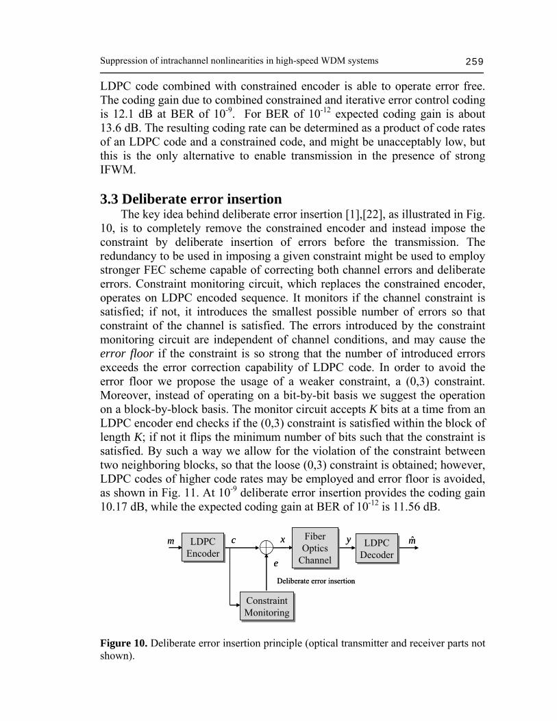
LDPC code combined with constrained encoder is able to operate error free. The coding gain due to combined constrained and iterative error control coding is 12.1 dB at BER of 10-9. For BER of 10-12 expected coding gain is about 13.6 dB. The resulting coding rate can be determined as a product of code rates of an LDPC code and a constrained code, and might be unacceptably low, but this is the only alternative to enable transmission in the presence of strong IFWM. 3.3 Deliberate error insertion The key idea behind deliberate error insertion [1],[22], as illustrated in Fig. 10, is to completely remove the constrained encoder and instead impose the constraint by deliberate insertion of errors before the transmission. The redundancy to be used in imposing a given constraint might be used to employ stronger FEC scheme capable of correcting both channel errors and deliberate errors. Constraint monitoring circuit, which replaces the constrained encoder, operates on LDPC encoded sequence. It monitors if the channel constraint is satisfied; if not, it introduces the smallest possible number of errors so that constraint of the channel is satisfied. The errors introduced by the constraint monitoring circuit are independent of channel conditions, and may cause the error floor if the constraint is so strong that the number of introduced errors exceeds the error correction capability of LDPC code. In order to avoid the error floor we propose the usage of a weaker constraint, a (0,3) constraint. Moreover, instead of operating on a bit-by-bit basis we suggest the operation on a block-by-block basis. The monitor circuit accepts K bits at a time from an LDPC encoder end checks if the (0,3) constraint is satisfied within the block of length K; if not it flips the minimum number of bits such that the constraint is satisfied. By such a way we allow for the violation of the constraint between two neighboring blocks, so that the loose (0,3) constraint is obtained; however, LDPC codes of higher code rates may be employed and error floor is avoided, as shown in Fig. 11. At 10-9 deliberate error insertion provides the coding gain 10.17 dB, while the expected coding gain at BER of 10-12 is 11.56 dB.
m̂yFiber Optics
Channel
Fiber Optics
Channel
m xcLDPCEncoderLDPC
EncoderLDPC
DecoderLDPC
Decoder
ConstraintMonitoringConstraintMonitoring
e
Deliberate error insertion
m̂yFiber Optics
Channel
Fiber Optics
Channel
m xcLDPCEncoderLDPC
EncoderLDPC
DecoderLDPC
Decoder
ConstraintMonitoringConstraintMonitoring
e
Deliberate error insertion
Figure 10. Deliberate error insertion principle (optical transmitter and receiver parts not shown).
Ivan B. Djordjevic 260
0.1 0.011x10⁻⁹
1x10⁻⁷
1x10⁻⁵
1x10⁻³
1x10⁻¹
40 Gb/s
Bit-
erro
r rat
e, B
ER
Uncoded signal bit-error rate, BERuncoded
LDPC(4320,3240,0.75) Deliberate error insertion:
loose (0,3)-constraint
Figure 11. BER performance of deliberate error insertion scheme for K=4. LDPC code belongs to the class of block-circulant codes. 4. Nonlinear BCJR equalization (turbo equalization) in supression of intrachannel nonlinearities Bahl, Cocke, Jelinek and Raviv proposed a (MAP) decoding algorithm (known as the BCJR algorithm) [21] that can be used for decoding of sequences generated by a finite state machine. It is an optimal decoding method that minimizes the symbol error probability. Applications suggested in [21] include convolutional and linear block codes, and recently it has been shown that BCJR algorithm can be used to successfully counter the effects of ISI in magnetic recording channels [14]. The output of the channel is described by a trellis, and BCJR operates on this trellis to correct the corrupted data. A significant benefit of using the BCJR algorithm, compared to Viterbi algorithm, is that in addition to detected bits it also provides bit reliabilities, i.e. soft decisions. Iterative decoding and LDPC coding is currently the most advanced forward error correction approach, but its power can be fully exploited only if bit reliabilities are supplied to the decoder. Although an optimal method for minimizing the sequence error probability, the Viterbi algorithm provides only hard decisions, thus preventing soft iterative decoding. We propose to use the BCJR algorithm to suppress the nonlinear ISI due to intrachannel nonlinearities. The BCJR algorithm operates on a trellis that is a discrete dynamical model of the optical channel. Let us suppose that a dispersion map is chosen so that each decoded bit is influenced by m neighboring bits from either side. Let
Suppression of intrachannel nonlinearities in high-speed WDM systems 261
uj be jth bit in a sequence u, and yj be corresponding received sample at the output of the electrical filter. The transition probability p(yj|s) is estimated from simulator by modeling the channel as a finite-state machine (s denotes the state of the channel). It is assumed that m previous and m next bits influence the observed bit uj, and the state of the channel s=(uj-m, uj-m+1,…, uj, uj+1,…, uj+m) is determined by a sequence of 2m+1 input bits ui∈{0,1}. The value 2m+1 is referred to as a memory of the discrete channel given by the set of states S. Notice that other approaches based on MLSD or turbo equalization, presented in [12]-[14], ignore the post-cursor ISI (the bits that follow the bit to be decoded). As an illustration, Fig. 12 shows the conditional probability density function (PDF) of the received sample y given a state s for the following two states s=1110111 and s=0001000 and different number of spans, for dispersion map from Fig. 5. Dispersion map in Fig. 5 is selected in such a way: (i) to keep IXPM low, and (ii) to keep the pulse spread during transmission over a D+ fiber in order of tens of bit periods (rather than hundreds of bit periods that is common for pseudolinear transmission). Notice that assumed memory in both cases is 2m+1=7. The parameters of D+ and D- fibers are given in Section 3.1. The span length is set to L=120 km, and each span consists of 2L/3 km of D+ fiber followed by L/3 km of D- fiber. Pre-compensation of -800 ps/nm and corresponding post-compensation are also applied. RZ modulation format of a duty cycle of 33% is observed, and the launched power is set to 0 dBm.
Figure 12. Estimated conditional PDFs for states s=1110111 and s=0001000 and for different number of spans.
Ivan B. Djordjevic 262
Erbium-doped fiber amplifiers with noise figure of 5 dB are deployed after every fiber section, the bandwidth of optical filter is set to 3Rb and the bandwidth of electrical filter to 0.65Rb, with Rb being the bit rate (40 Gb/s). As expected, by increasing the number of spans, the ghost pulse at the central bit position grows, causing the mean of the PDF to shift to the right [Fig. 12]. It is obvious that the commonly used AWGN assumption is not valid in this case. The PDF is obtained by passing random sequences through the channel. The length of a sequence is 215, and 32 samples per bit are used in the transmission simulations. To estimate the PDF, the sample range is uniformly quantized in 64 bins, and the number of occurrences of samples in a given bin is counted and normalized with total number of samples. A set of triples (previous state, channel output, next state) uniquely defines a finite state machine on which the BCJR operates. As an illustration a trellis for 2m+1=5 is shown in Fig. 13(a). It has 32 states (s0, s1,…, s31), and each state is given by a different 5-bit pattern. The states in vertical columns represent all possible states that the channel (or FSM) can take at a given time instant, while the labeled edges represent possible transitions. Neighboring columns thus represent consecutive time instants. For example, if the channel is in state s0 (the bit pattern 00000 was generated), and if the next bit is “0”, the FSM stays in state s0 and generates “0” as an output (the middle bit of the final state). Otherwise, the FSM goes to state s1 (bit pattern 00001) and outputs again “0”. If the FSM is in s16 (the bit pattern 10000 was generated), and if the next bit is “0”, then the FSM goes to s0 and outputs “0” (the middle bit of the terminal state), otherwise it goes to s1 (bit pattern 00001) and outputs again “0”. No other transition is allowed from s16. Similarly, there are two possible transitions from each state in the trellis. A labeled edge is assigned to each allowed transition, and a received sample corresponds to the output symbol of the branch (the central bit of the terminal state). Given s’-the previous state, s=(uj-m,uj-m+1,…,uj,uj+1,…,uj+m)-the present state, u=(u1,u2,…, un)-the transmitted codeword, and y=(y1,y2,…,yn)-the received sequence, the log-likelihood ratio (LLR) (denoting the bit reliability) of uj (j=1,2,…,n), is calculated as ( )
( )( ) ( ) ( )
( )( ) ( ) ( )1 1
', : 0 ', : 1max* ' ', max* ' ', .j j j j j j j
u uj j
L u α γ β α γ β− −= =⎡ ⎤ ⎡ ⎤= + + − + +⎣ ⎦ ⎣ ⎦
s s s ss s s s s s s s
(8) The dashed lines in Fig. 13(a) corresponds to transitions (s’,s): uj=0, and the solid lines to transitions (s’,s): uj=1. The forward metric,
1( )=log ( = , )jj jpα s s s y
(see Fig. 13(b)), is given by
Suppression of intrachannel nonlinearities in high-speed WDM systems 263
Figure 13. (a) Trellis used by BCJR (for 2m+1=5), (b) the forward step of BCJR, and (c) the backward step of BCJR.
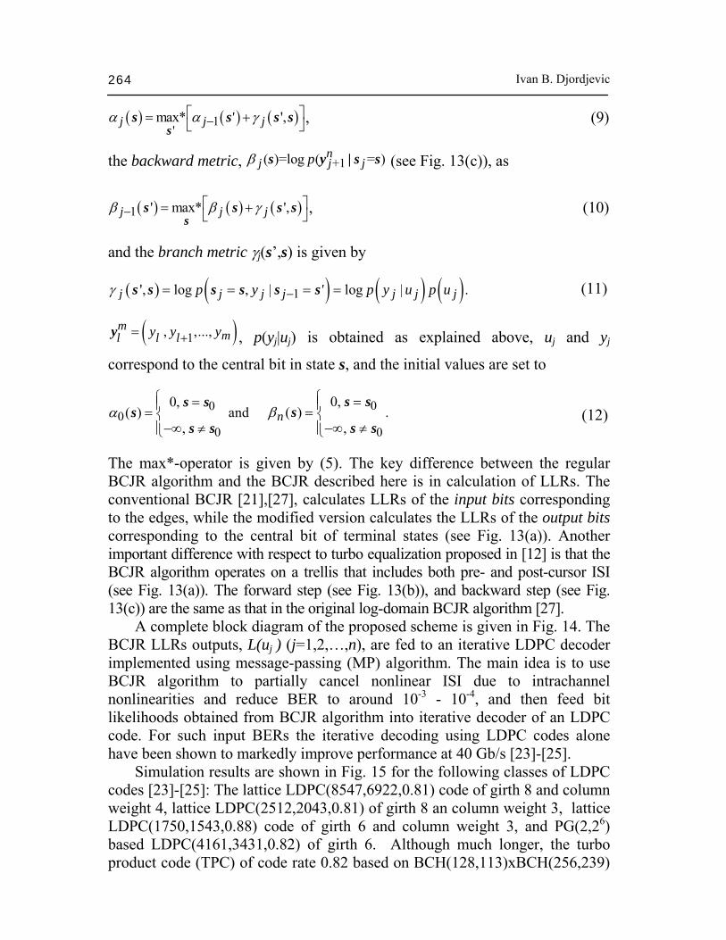
Ivan B. Djordjevic 264
( ) ( ) ( )1'
max* ',j j j'α α γ−⎡ ⎤= +⎣ ⎦ss s s s , (9)
the backward metric, +1( )=log ( = )n
j j jpβ s y | s s (see Fig. 13(c)), as
( ) ( ) ( )1 ' max* ',j j jβ β γ− ⎡ ⎤= +⎣ ⎦ss s s s , (10)
and the branch metric γj(s’,s) is given by
( ) ( ) ( ) ( )1', log , | log | .j j j j j j jp y ' p y u p uγ −= = = =s s s s s s
(11)
( )1, ,...,m
ml l ly y y+=y , p(yj|uj) is obtained as explained above, uj and yj
correspond to the central bit in state s, and the initial values are set to
00
0
0,( ) and
,α
⎧ =⎪= ⎨−∞ ≠⎪⎩
s ss
s s
0
0
0,( ) .
,nβ
⎧ =⎪= ⎨−∞ ≠⎪⎩
s ss
s s (12)
The max*-operator is given by (5). The key difference between the regular BCJR algorithm and the BCJR described here is in calculation of LLRs. The conventional BCJR [21],[27], calculates LLRs of the input bits corresponding to the edges, while the modified version calculates the LLRs of the output bits corresponding to the central bit of terminal states (see Fig. 13(a)). Another important difference with respect to turbo equalization proposed in [12] is that the BCJR algorithm operates on a trellis that includes both pre- and post-cursor ISI (see Fig. 13(a)). The forward step (see Fig. 13(b)), and backward step (see Fig. 13(c)) are the same as that in the original log-domain BCJR algorithm [27]. A complete block diagram of the proposed scheme is given in Fig. 14. The BCJR LLRs outputs, L(uj ) (j=1,2,…,n), are fed to an iterative LDPC decoder implemented using message-passing (MP) algorithm. The main idea is to use BCJR algorithm to partially cancel nonlinear ISI due to intrachannel nonlinearities and reduce BER to around 10-3 - 10-4, and then feed bit likelihoods obtained from BCJR algorithm into iterative decoder of an LDPC code. For such input BERs the iterative decoding using LDPC codes alone have been shown to markedly improve performance at 40 Gb/s [23]-[25]. Simulation results are shown in Fig. 15 for the following classes of LDPC codes [23]-[25]: The lattice LDPC(8547,6922,0.81) code of girth 8 and column weight 4, lattice LDPC(2512,2043,0.81) of girth 8 an column weight 3, lattice LDPC(1750,1543,0.88) code of girth 6 and column weight 3, and PG(2,26) based LDPC(4161,3431,0.82) of girth 6. Although much longer, the turbo product code (TPC) of code rate 0.82 based on BCH(128,113)xBCH(256,239)
Suppression of intrachannel nonlinearities in high-speed WDM systems 265
scheme lags far behind different classes of LDPC codes. For example, LDPC(8547,6922,0.81) code alone outperforms TPC by 0.8 dB at BER of 10-6, although it is almost 4 times shorter. Viterbi decoder operates on trellis shown in Fig. 13(a) with the truncation length 64, and performs comparable to BCJR algorithm (see Fig. 15(a)). Notice, however, that it does not provide soft decisions required for soft iterative decoding of the outer LDPC code. For the memory 2m+1=7 the lattice girth-8 LDPC code of rate 0.81 and column weight 4, combined with BCJR algorithm, outperforms the TPC by 2.5 dB at BER of 1⋅10-6, BCJR algorithm alone by 6.8 dB, and the coding gain over an uncoded system is 9.2 dB. By iterating (passing the bit LLRs) between the BCJR algorithm block and the LDPC decoder (see Fig. 14), the BER performance can be further improved on the expense of an increased decoding delay. We refer to this as an outer iteration, to differentiate it from iterations within the message passing algorithm, which are referred to as inner iterations. In the first outer iteration, the LLRs from BCJR are passed to and processed by the message-passing decoder. We say that the i-th outer iteration is complete when the extrinsic LLRs at the output of the MP decoder from the (i-1)-th iteration are processed by BCJR detector and the BCJR extrinsic reliabilities are passed to and processed by the MP decoder. The number of inner iterations in the message-passing decoder is set to 10. The curves with only one outer iteration are obtained for 25 inner iterations of MP decoder. The coding gain after the firth iteration is 9.7 dB at BER of 1⋅10-6 (the diamond curve in Fig. 15(a)). The improvement in coding gain over TPC is 3 dB (at the same BER), and the improvement over the BCJR detector is 7.3 dB. By extrapolating the LDPC(8547,6922,0.81) curve down to BER of 10-12 the expected coding gain is around 13.1 dB, and the improvement over TPC is around 3.2 dB. We have recently shown [29] that the finite geometry codes, and lattice codes of high girth and large column weight, do not exhibit an error floor in the region of interest for fibre-optics communications, so that the interpolation is justifiable once the waterfall region is reached. The BER performance can be also improved by increasing the memory of the channel, but it results in an exponential increase of the algorithm complexity.
Figure 15. BER performance of combined BCJR-LDPC scheme (a), and BER performance comparison for different LDPC codes (b). From the numerical results presented above, it follows that the combined BCJR intrachannel cancellation and LDPC coding is an excellent candidate to enable transmission in the presence of strong intrachannel nonlinearities. Moreover, it can be used for upgrading the existing 10 Gb/s infrastructure to 40 Gb/s. The BER performance comparison of combined nonlinear ISI cancellation and LDPC coding for different component LDPC codes is given in Fig. 15(b). As expected, the girth-8 codes outperform the girth-6 codes. The coding gains of combined BCJR-LDPC scheme for different channel memories, and LDPC(8547,6922,0.81) code as component code, at BER of 10-6 are summarized in Table 2. The max*-operator in (8)-(10) involves a two-input max-function and the function for the correction term log(1+e-|x-y|) that can be implemented as a lookup table. The performance loss by approximating the max*-function by max-function is found to be negligible (see Fig. 15(b)). In calculation of BER performance (in Fig. 15), an encoded sequence of length 215 is transmitted many times over the transmission system for different ASE noise realizations. The number of spans is varied from 20 to Table 2. Coding gains of combined BCJR-LDPC scheme for different channel memories at BER of 1⋅10-6.
Suppression of intrachannel nonlinearities in high-speed WDM systems 267
70 and the BERs of uncoded and coded case are recorded. In fiber-optics communications the Q-factor is commonly used as a figure of merit instead of signal-to-noise ratio. However, the Q factor is not an appropriate figure of merit in a highly nonlinear optical channel. The x-axis in Fig. 15 corresponds to the BER of an uncoded signal, when both BCJR block and LDPC decoder are omitted. 5. Noise-predictive BCJR equalization (turbo equalization) in supression of intrachannel nonlinear effects The block scheme of the proposed noise-predictive BCJR equalization scheme is shown in Fig. 16. The novelty with respect to the scheme presented in Section 4 is the introduction of the noise-predictive FIR filter. Its role is to deal with colored noise due to ASE noise and partially to deal with ISI introduced by residual dispersion and (optical/electrical) filtering. The key idea is to reduce the trellis complexity of BCJR equalization scheme from previous Section by estimating the colored noise by the linear noise-predictive FIR filter. In previous Section the BCJR algorithm is used to deal with both the linear and nonlinear impairments. Here we use the BCJR algorithm to deal with intrachannel nonlinearities only. If p(D)=p1D+p2D2+…+pNDN
represents the transfer polynomial of the FIR noise prediction filter of length N, then 1-p(D) represents the transfer polynomial of the prediction error filter, and the noise prediction error, defined as the difference of the exact noise sample wn and the noise predicted sample nw can be
Given the autocorrelation function Rw, the coefficients of noise predictor filter are determined by solving the system of well-known normal (Yule-Walker) equations [16]:
Ivan B. Djordjevic 268
( ) ( )1
; 1,2,..., N
w j wj
R i p R i j i N=
= − =∑
(14)
To solve the system of equations (14) an efficient method due to Burg [39] is used. It involves a recursive procedure of increasing the order of the filter one unit at a time, and re-estimating the filter coefficients on such a way to minimize the mean-square error defined as [16].
( ) ( )2
10 .
Nn w i w
iE e R p R i
=⎡ ⎤ = − ∑⎣ ⎦
(15)
Notice that the system of equations (14) has to be solved only once, before the start of a transmission, for example by using a short training sequence and collecting noise samples in the receiver. The length of FIR noise predictive filter needs to be chosen carefully in order to avoid error propagation. We have found that the length of 16 is sufficient for nonlinear fiber-optics channels. To reduce the number of coefficients employed in the noise predictive filter, an infinite impulse response (IIR) filter may be used instead. The second component of the NP-BCJR nonlinear equalizer described here is the BCJR equalizer, similar to that described in previous Section. The only difference is that the transition PDFs p(yj|s), s∈S are determined after removal of predicted noise samples (yj represent the sample at the input of the BCJR detector that corresponds to the transmitted bit uj, and S is the set of states in the trellis). The BER performance comparison of NP-BCJR equalizer scheme combined with the lattice LDPC(8547,6922,0.81) code of girth 8 and column weight 4 against corresponding scheme without noise prediction is given in Fig. 17 for different memories in the channel trellis. Notice that BER performance improvement due to noise-predictive filtering is negligible for the channel memories up to 2m+1=5. For the memory 2m+1=7, the NP-BCJR equalizer BER approaches (in limit) that of BCJR equalizer with memory 2m+1=9, facilitating therefore the implementation at high-speed. Better BER improvement is expected when the EDFAs with higher noise figure are employed. The coding gain of NP-BCJR equalizer (with memory 7) supplemented with LDPC decoder over an uncoded signal is about 9.3 dB (at BER of 1⋅10-6 for 25 iterations in MP decoder). For comparison purposes, the TPC BER curve is inserted as well. By iterating between BCJR equalizer block and the LDPC decoder, the BER performance can be further improved (on the expense of an increased decoding delay). At BER of 10-6 the coding gain improvement in 5th iteration (for 10 iterations in MP decoder), over uncoded case is around 10dB. The expected coding gain at BER of 10-12, obtained by extrapolation, is around 13.4 dB. We have recently shown [29] that the finite geometry codes and lattice codes of high girth do not exhibit an error floor in
Suppression of intrachannel nonlinearities in high-speed WDM systems 269
Figure 17. BER of NP-BCJR equalizer (a) supplemented with LDPC decoder (b). the region of interest for fiber-optics communications, so that the interpolation is justifiable once the waterfall region is reached. The results of simulations are obtained by maintaining a double precision of LLRs. We have recently shown in [34] that proper choice in number of quantization bits results in negligible BER performance loss. Notice that recent advances in ultra-high speed microelectronics and electro-optics technology allowed successful demonstration of ETDM-based optical transmission above 80 Gb/s [32], while MLSD is intensively studied for 40 Gb/s transmission [33], suggesting that the nonlinear BCJR equalization schemes described in this chapter are timely. 6. Modulation techniques in supression of intrachannel nonlinearities In this section we present an efficient method for suppression of IFWM by choosing the initial pulse phases in such a way to minimize the effect of different ghost-pulse contributors at the zero-bit position being in “resonance” instead of canceling them, without reducing the code rate. It is based on our recent article [36]. We define the new figure of merit for assessing the influence of IFWM, and use it to select a better modulation format among several ones depending on information content. The numerical example combines the method due to Gill et al. in [37] (G) and the technique due to Zou et al. in [38] (Z). G basically assigns alternating phases of difference π/2 to the bits in the original sequence such as (π/2, 0, π/2, 0, …), while Z applies a fixed eight-bit phase pattern to the sequence. In our IFWM cancellation approach the information is transmitted by presence or absence of a pulse (OOK), and the parasite phase modulation is used as a mean to disturb the
Ivan B. Djordjevic 270
phase coherence of the bits being involved in the ghost pulse creation process. The presented modulation technique significantly outperforms G and Z. In terms of both Q-factor and bit-error rate (BER). It was shown in Section 3.1 that proper choice of initial phases may result in suppression of IFWM. The IFWM will be suppressed in any sub-sequence of length L, cici+1…ci+L-1, if the following complex ghost-pulse constraint is satisfied: for all integers k, l, m∈{i,i+L-1} such that ck = cl = cm=1 (k and l not necessarily distinct), choose the initial phases θk, θl and θm such that their contribution cancel each other at resonant position k+l-m, i.e.
( )0
j mk lS eθ θ θ+ −
= =∑ , (16)
where the summation is done over all (k,l,m)∈ {i,i+L-1} triples for which ck=cl=cm=1. Satisfying this constraint is hard to achieve, without sacrificing the code rate (see Section 3). Notice that constraint (16) has also to be satisfied in any two successive sub-sequences of length L as well. So, the idea presented in this section is to select a simple almost fixed-phase pattern sequence minimizing summation S in (16), and to provide a Q-factor improvement over 6.5 dB which is provided by G. The parameter S in (16) may be used as a figure of merit of a particular modulation format. We may observe a particular zero bit position in a sequence of length L, and calculate S for different information content. In Fig. 18 the parameter |S| versus the information content, given in decimal representation (the binary sequence of length L=9 is represented as an integer), is compared for three different modulation formats. Only the combinations ranging from 190-240 with middle bit being zero are observed, this range has been chosen to demonstrate the general case where G results in a smaller S and some cases where Z minimizes S. In Fig. 18 G is compared against Z and RZ-OOK. However, other modulation techniques such as the alternate mark inversion (AMI), might perform better for some specific bit sequences such as the bit sequence “010101010”. AMI and similarly duobinary formats assign optical phases to the pulses so that different contributions to ghost pulse creation cancel each other at resonant bit position. Moreover in some other cases, Z might even outperform G such as the bit sequence “111101111” which is considered to be the most troublesome bit sequence in terms of ghost pulse generation. Taking the two bit sequences mentioned above, and testing the summation |S| at the middle bit, the results show that for “010101010” |S|= 0,0,6,6 and for “111101111” |S|= 8,12,12,24for Z, AMI, G and RZ-OOK respectively. After all, for a PRBS input G performs better that the other techniques. These observations lead us to a conclusion to combine G with Z to form a new phase modulation scheme that further
Suppression of intrachannel nonlinearities in high-speed WDM systems 271
(a) (b)
Figure 18. The parameter |S| versus the information content, denoted in decimal representation, for different modulation techniques: (a) G and Z, (b) the regular RZ-OOK. minimizes the sum S. The combination mainly depends on finding which scheme among the two gives out the least sum S for a specific 8-bit block of the data sequence and assign it to the bits in the original sequence. The parameter S is pre-calculated before transmission starts, and the results are stored in a lookup table. Notice that only sub-sequences for which Z outperforms G are to be stored. Since the general trend is that in most of the cases G is better then Z, the length of the lookup table is reasonable small for high-speed implementation. Similarly as G and Z, the proposed modulation technique requires an additional phase modulator, compared to regular RZ-OOK transmitter. The simulations were run on a realistic dispersion-managed 40 Gb/s single-channel system, and dispersion map is given in Fig. 5. The span length is set to L=120 km, and each span consists of 2L/3 km of D+ fiber followed by L/3 km of D- fiber. Pre-compensation of -800ps/nm and corresponding post-compensation are also applied. The parameters of D+ and D- fibers are as given in Table 1. RZ modulation format of a duty cycle of 33% is observed, and the launched power is set to 0dBm. Erbium-doped fiber amplifiers (EDFAs) with noise figure of 5dB are deployed after every fiber section, the bandwidth of optical filter is set to 2Rb and the bandwidth of electrical filter to 0.65Rb, with Rb being the bit rate (40 Gb/s). Fig. 19 shows the eye diagrams after 35 spans for two inputs: a regular PRBS input of order 15, and an input that focuses on the most troublesome blocks observing different modulation schemes of the same length as the PRBS. It is obvious that the eye diagram for the RZ-OOK is highly disturbed, while the eye diagram for proposed modulation format is wide open and the
Ivan B. Djordjevic 272
R
Z
G
C
D
V
olta
ge, V
[mV
]
Figure 19. Eye diagrams (at the output of optical filter) after 35 spans. The columns from left to right: (1) PRBS input using described dispersion map with pre-compensation of -800ps/nm, (2) troublesome input using the same parameters, and (3) PRBS input with pre-compensation of -1600ps/nm. The rows: (R) RZ-OOK, (Z) Zou’s technique, (G) Gill’s technique, (C) proposed technique, and (D) RZ-DPSK. eye diagram for G shows a highly improved eye diagram compared to the RZ-OOK yet not as good as the proposed modulation. This is valid for both types of input. Since the troublesome sequences in the PRBS sequences occur with certain probability the improvement in the PRBS case is lower. The same simulator was run while changing the pre-compensation to -1600ps/nm, and the results are shown in Fig. 19.
Suppression of intrachannel nonlinearities in high-speed WDM systems 273
Fig. 20 shows the Q-factor improvement over the RZ-OOK, for G, Z, RZ-DPSK, and the proposed modulation technique. It can be noticed that G format achieves the maximum improvement of 7.5dB, Z achieves an improvement of 3.8dB, while 9dB is achieved by the proposed modulation technique. The RZ-DPSK with a balanced-receiver, although employing more complicated receiver, performs worse than proposed modulation technique and provides a maximum improvement of 8.5dB. The improvement for a troublesome input is better than that for regular PRBS input, because for troublesome input Z was employed instead of G resulting in better suppression of ghost-pulse effect. In Fig. 21(a) the proposed modulation technique is compared against G and Z in terms of bit-error rate (BER), obtained by counting of errors. As expected, the proposed modulation technique outperforms G, and significantly outperforms Z. In Fig. 21(b) the BER performance are shown when LDPC(8547,6922) code of girth-8 (the length of shortest cycle in corresponding bipartite graph), is employed in simulations. This LDPC code has a rate of 0.81, the number of information bits is 6922, and the codeword length is 8547. Significant performance improvement over LDPC coded RZ-OOK is obtained, with coding gains comparable to that reported in Section 3, but with lower complexity. To generate the numerical results in Fig. 21 the sequence of length 215-1 is transmitted many times over whole transmission systems for different numbers of spans in the range of 10 to 60, and different ASE noise realizations. Notice that for the proposed modulation technique supplemented with LDPC code, we were not able to count any error for number of spans up to 60.
(a) (b) Figure 20. Q-factor improvement over the RZ-OOK for: (a) PRBS input, and (b) troublesome input.
Ivan B. Djordjevic 274
(a) (b) Figure 21. BER for different modulation formats for: (a) uncoded case, and (b) LDPC coded case. 7. Conclusion We described and analyzed several novel methods to counter the effects of IFWM and IXPM: (1) constrained codes, (2) combined constrained and error control coding, (3) deliberate error insertion, (4) nonlinear BCJR equalization, (5) noise-predictive BCJR equalization, and (6) an advanced modulation technique. The constrained encoding is based on the following three principles: (a) the most troublesome sequences are identified and forbidden, (b) the zero-symbol in so called “resonant positions” is converted into one-symbol, and (c) the different contributions to a ghost pulse creation cancel each other in resonant positions. Significant Q-factor improvement, due to constrained coding, up to 16 dB, depending on code rate and number of spans, is demonstrated. At 40 Gb/s and above, constrained codes can significantly improve the transmission distance and system capacity. The coding gain due to combined constrained and iterative error control coding is 12.1 dB at BER of 10-9. For BER of 10-12 expected coding gain is about 13.6dB. The ability of constrained codes to substantially reduce the timing jitter due to IXPM is also important in enabling the clock recovery, which would be quite challenging when the eye diagram is completely closed. The MAP detection based on BCJR algorithm supplemented with iterative decoding is able to achieve significant performance improvement in systems heavily degraded by ISI due to intrachannel fiber nonlinearities and dispersion. We note that other techniques for suppression of intrachannel nonlinearities, such the ones based on MLSD (Viterbi algorithm), do not provide soft outputs required for soft iterative (turbo or LDPC) decoding. For memories above 2m+1=7, the complexity of BCJR becomes large, and a simplified version of
Suppression of intrachannel nonlinearities in high-speed WDM systems 275
it, namely soft-output Viterbi algorithm (SOVA) [26] is more likely to be of interest for practical implementations. To reduce the number of states in trellis on which BCJR algorithm operates the concept of noise-predictive BCJR equalization is introduced. The coding gain improvement of NP-BCJR in 5th iteration (for 10 iterations in MP decoder), over uncoded case is around 10dB, and the improvement over TPC is around 3.2 dB. The expected coding gain at BER of 10-12, obtained by extrapolation, is around 13.4 dB. The novel figure of merit suitable for testing the influence of IFWM is introduced. Using this figure of merit, the novel modulation technique that selects better modulation format among several ones for sequence being in resonance is proposed. With minimal modifications applied to Gill’s method [37], the method presented herein can result in up to 2dB improvement in Q-factor. The system performance can be further improved by using more than two different modulation formats, at the expense of increased complexity. Most of dispersion maps used in 10 Gb/s systems will suffer from strong intrachannel nonlinearities if used for 40 Gb/s transmission without any modifications. The proposed schemes are, therefore, excellent candidates for a 40 Gb/s upgrade over existing 10 Gb/s infrastructure. Moreover, the proposed schemes require only the modifications on transmitter and receiver sides of a transmission system. Turbo equalization principle is also suitable to deal with other channel impairments such as PMD, and residual chromatic dispersion. Acknowledgment The author would like to thank Hussam G. Bathson, Bane Vasic and Varsha S. Rao for their involvement in earlier work on suppression of intrachannel nonlinearities. References 1. I. B. Djordjevic, and B. Vasic, “Constrained coding techniques for suppression of
Intrachannel Nonlinear effects in high-speed optical transmission,” J. Lightw. Technol. 24, 411-419 (2006).
2. R.-J. Essiambre, B. Mikkelsen, and G. Raybon, “Intra-channel crossphase modulation and four-wave mixing in high-speed TDM systems,” Electron. Lett. 18, 1576–1578 (1999).
3. M. J. Ablowitz, and T. Hirooka, “Resonant nonlinear intrachannel interactions in strongly dispersion managed transmission systems,” Opt. Lett. 24, 1750–1752 (2000).
4. X. Liu, X.Wei, A. H. Gnauck, C. Xu, and L. K. Wickham, “Suppression of interchannel four-wave-mixinginduced ghost pulses in high-speed transmissions by phase inversion between adjacent marker blocks,” Opt. Lett. 27, 1177–1179 (2000).
Ivan B. Djordjevic 276
5. P. V. Mamyshev, and N. A. Mamysheva, “Pulse-overlapped dispersion-managed data transmission and intrachannel four-wave mixing,” Opt. Lett. 24, 1454 -1456 (1999).
6. N. Alic, and Y. Fainman, "Data-dependent phase coding for suppression of ghost pulses in optical fibers," IEEE Photon. Technol. Lett. 16, 1212-14 (2004).
7. J. H. Winters, “Equalization in coherent lightwave systems using a fractionally spaced equalizer,” J. Lightwave Technol. 7, 813-815 (1989).
8. S. Kasturia and J. H. Winters, “Techniques for high-speed implementation of nonlinear cancellation,” IEEE J. Sel. Areas Commun. 9, 711-717 (1991).
9. C. Xia, and W. Rosenkranz, “Performance enhancement for duobinary modulation through nonlinear electrical equalization,” in Proc. ECOC 2005, 2, 257-258 (2005).
10. E. Agazzi, M. R. Hueda, H. S. Carrer, and D. E. Crivelli, “Maximum-likelihood sequence estimation in dispersive optical channels,” J. Lightwave Technol. 23, 749-763 (2005).
11. N. Alić, G. Papen, R. Saperstein, L. Milstein, Y. Fainman, “Signal statistics and maximum likelihood sequence estimation in intensity modulated fiber optic links containing a single optical pre-amplifier,” Opt. Express 13, 4568-4579 ( 2005).
12. C. Douillard, M. Jézéquel, C. Berrou, A. Picart, P. Didier, and A. Glavieux, “Iterative correction of intersymbol interference: turbo equalization’” Eur. Trans. Telecommun. 6, 507-511 (1995).
13. S. Song, A. C. Singer, and K.-M. Sung, “Soft input channel estimation for turbo equalization,” IEEE Trans. Signal Process. 52 2885-2894 (2004).
14. B. M. Kurkoski, P. H. Siegel, and J. K. Wolf, “Joint Message-Passing decoding of LDPC codes and partial response channels,” IEEE Trans. Inf. Theory 48, 1410-1422 (2002).
15. I. Djordjevic, B. Vasic, "Nonlinear BCJR equalizer for suppression of intrachannel nonlinearities in 40 Gb/s optical communications systems," Opt. Express, vol. 14, pp. 4625-4635, May 29, 2006.
16. I. B. Djordjevic, B. Vasic, “Noise-Predictive BCJR Equalization for Suppression of Intrachannel Nonlinearities,” IEEE Photonics Technology Letters 18, 1317- 1319 (2006).
17. D. Lind and B. Marcus, Symbolic Dynamics and Coding, Cambridge, U.K.: Cambridge Univ. Press, 1995.
18. B. Marcus, P. Siegel, R. Roth, “An Introduction to Coding for Constrained Systems”, in Handbook of Coding Theory, (eds. W.C. Huffman and V. Pless), Elsevier Press, 1998.
19. W. G. Bliss, “Circuitry for performing error correction calculations on baseband encoded data to eliminate error propagation,” IBM Techn. Discl. Bul., vol. 23, pp. 4633-4634, 1981.
20. J. L. Fan, J. M. Cioffi, ”Constrained coding techniques for soft iterative decoders,” in Proc. Globecom’99, pp. 723-727, 1999.
21. L. R. Bahl, J. Cocke, F. Jelinek, and J. Raviv, “Optimal decoding of linear codes for minimizing symbol error rate,” IEEE Trans. Inf. Theory, IT-20, 284-287 (1974).
22. B. Vasic, K. Pedagani, “Run-Length-Limited Low-Density Parity-Check Codes Based on Deliberate Error Insertion,” IEEE Trans. Magnetics, vol. 40, pp. 1738-1743, May 2004.
Suppression of intrachannel nonlinearities in high-speed WDM systems 277
23. I. B. Djordjevic, and B. Vasic, “MacNeish-Mann theorem based iteratively decodable codes for optical communication systems,” IEEE Commun. Lett. 8, 538-540 (2004).
24. I. Djordjevic, S. Sankaranarayanan, B. Vasic, “Projective plane iteratively decodable block codes for WDM high-speed long-haul transmission systems,” J. Lightwave Technol. 22, 695-702 (2004).
25. B. Vasic, I. B. Djordjevic, and R. Kostuk, “Low-density parity check codes and iterative decoding for long haul optical communication systems,” J. Lightwave Technol. 21, 438-446 (2003).
26. J. Hagenauer and P. Hoeher, “A Viterbi algorithm with soft decision outputs and its applications,” in Proc. IEEE GLOBECOM, 1680-1686 (1989).
27. W. E. Ryan, “Concatenated convolutional codes and iterative decoding,” in Wiley Encyclopedia of Telecommunications, J. G. Proakis, ed., (John Wiley and Sons, 2002).
28. S. K. Chilappagari, S. Sankaranarayanan, B. Vasic, “Error floors of LDPC codes on binary symmetric channel,” in Proc. ICC 2006, Istanbul, Turkey on 11 - 15 June 2006.
29. I. B. Djordjevic, S. Sankaranarayanan , S. K. Chilappagari, B. Vasic, “Low-Density Parity-Check Codes for 40 Gb/s Optical Transmission Systems,” IEEE/LEOS Journal of Selected Topics in Quantum Electronics 12, 555-562 (2006).
30. T. Mizuochi et al., “Forward error correction based on block turbo code with 3-bit soft decision for 10 Gb/s optical communication systems,” IEEE J. Sel. Top. Quantum Electron. 10, 376-386 (2004).
31. M. Mansour, "Implementation of LDPC decoders," presented at the IEEE Comm. Theory Workshop, Park City, UT, June 13-15, 2005.
32. T. Lee, “80+ Gb/s ETDM systems implementation: an overview of current technology,” in Proc. OFC 2006, Paper no. OTuB3.
33. A. Färbert, “Application of digital equalization in optical transmission systems,” in Proc. OFC 2006, Paper no. OTuE5.
34. S. Sankaranarayanan, I. B. Djordjevic, and B. Vasic, “Iteratively decodable codes on m-flats for WDM high-speed long-haul transmission,” J. Lightw. Technol. 23, 3696-3701 (2005).
35. G. P. Agrawal, Nonlinear Fiber Optics. SD: Academic, 2001. 36. H. Batshon, I. B. Djordjevic, B. Vasic, “An Improved Technique for Suppression
of Intrachannel Four-Wave-Mixing in 40 Gb/s Optical Transmission Systems,” IEEE Photonics Technol. Lett., vol. 19, no. 2, pp. 67-69, Jan. 15, 2007.
37. D. M. Gill, X. Liu, X.Wei, S. Banerjee and W. Su “π/2 Alternate-Phase ON-OFF Keyed 40-Gb/s Transmission on Standard Single-Mode Fiber,” IEEE Photon. Technol. Lett. 15, 1776-1778 (2003).
38. M. Zou, M. Chen, and S. Xie, “Suppression of ghost pulses in 40Gbps optical transmission systems with fixed-pattern phase modulation,” Opt. Express 13, 2251-2255 (2005).
39. J. P. Burg, “A New Analysis Technique for Time Series Data,” NATO Adv. Study Inst., Sig. Proc. with Emphasis on Underwater Acoust., Aug. 1968.