28


TABLE OF CONTENTS
_____ v
TABLE OF CONTENTS
FOREWORD xiii
PREFACE xv
NOTATIONS xix
Chapter 1 INTRODUCTION 1 1.1. Relations between different Eurocodes 1 1.2. Scope of EN 1993-1-2 3 1.3. Layout of the book 3
Chapter 2 MECHANICAL LOADING 7 2.1. General 7 2.1.1. General rule 7 2.1.2. Simplification 1 10 2.1.3. Simplification 2 10 2.1.4. Simplification 3 12 2.2. Examples 13 2.3. Indirect actions 14
Chapter 3 THERMAL ACTION 17 3.1. General 17 3.2. Nominal temperature-time curves 18 3.3. Parametric temperature-time curves 21 3.4. Zone models 29 3.5. CFD models 31 3.6. Localised fires 32 3.7. External members 39

TABLE OF CONTENTS
_____ vi
Chapter 4 TEMPERATURE IN STEEL SECTIONS 45 4.1. Introduction 45 4.2. The heat conduction equation and its boundary conditions 45 4.3. Advanced calculation model. Finite element solution of the heat conduction equation 47 4.3.1. Temperature field using the finite element method 48 4.4. Section factor 51 4.5. Temperature of unprotected steelwork exposed to fire 54 4.6. Temperature of protected steelwork exposed to fire 61 4.7. Internal steelwork in a void protected by heat screens 76 4.8. External steelwork 78 4.8.1. General principles 78 4.8.2. Example 80 4.9. View factors in the concave part of a steel profile 88 4.10. Temperature in steel members subjected to localised fires 92 4.10.1. Unprotected steel members 92 4.10.2. Protected steel members 93 4.10.3. Thermal response of steel members in case of multiple localised fires 95
4.10.3.1. Multiple localised fires due to simultaneously burning cars: an example of a car park 95 4.10.3.1.1. Characterization of the fire and definition of the fire scenarios 95 4.10.3.1.2. Temperature of the main beam 98
4.11. Temperature in stainless steel members 101 4.11.1. Example 104
Chapter 5 MECHANICAL ANALYSIS 105 5.1. Basic principles 105 5.2. Mechanical properties of carbon steel 110 5.3. Classification of cross sections 115

TABLE OF CONTENTS
_____ vii
5.3.1. Cross section under combined bending and axial-compression at normal temperature 120
5.3.1.1. First methodology for Class 1 and Class 2 cross sections 123 5.3.1.2. Second methodology for the case of Class 1 and
Class 2 cross sections 125 5.3.1.3. First methodology for Class 3 cross sections 127 5.3.1.4. Second methodology for Class 3 cross sections 128 5.3.1.5. Advantages and disadvantages of the two presented
methodologies 130 5.3.2. Cross section under combined bending and tension at normal
temperature 132 5.3.3. Classification under fire conditions 132 5.4. Effective cross section 134 5.5. Fire resistance of structural members 136 5.5.1. General 136 5.5.2. Members with Class 4 cross sections 138 5.5.3. Tension members 139 5.5.4. Compression members 140 5.5.5. Shear resistance 143 5.5.6. Laterally restrained beams 145 5.5.6.1. Uniform temperature distribution 145 5.5.6.2. Non-uniform temperature distribution 147 5.5.6.3. Bending and shear 150 5.5.7. Laterally unrestrained beams 152 5.5.7.1. The elastic critical moment for lateral-torsional buckling 152 5.5.7.2. Resistance to lateral-torsional buckling 156 5.5.8. Members subjected to combined bending and axial compression 159 5.5.9. Some verifications of the fire resistance not covered by EN 1993-1-2 163 5.5.9.1. Shear buckling resistance for web without intermediate
stiffeners 163 5.5.9.2. Cross section verification of a member subjected to combined bending and axial force (compression or tension) 164
TABLE OF CONTENTS
_____ viii
5.5.9.2.1. Class 1 and 2 rectangular solid sections 165 5.5.9.2.2. Class 1 and 2 doubly symmetric I- and H-sections 166 5.5.9.2.3. Class 3 doubly symmetric I- and H-sections 168 5.5.9.2.4. Class 4 cross sections 169 5.5.9.3. Bending, shear and axial force 169 5.6. Design in the temperature domain. Critical temperature 170 5.7. Design of continuous beams 180 5.7.1. General 180 5.7.2. Continuous beams at room temperature 181 5.7.3. Continuous beams under fire conditions 184 5.8. Fire resistance of structural stainless steel members 186 5.9. Design examples 193 Chapter 6 ADVANCED CALCULATION MODELS 273 6.1. General 273 6.2. Thermal response model 275 6.3. Mechanical response model 282 6.4. Some comparisons between the simple and the advanced calculation models 288 6.4.1. Shadow factor 289 6.4.2. Buckling curves 293 6.4.3. Factor κ2 295 6.4.4. Factor κ1 296 Chapter 7 JOINTS 299 7.1. General 299 7.2. Strength of bolts and welds at elevated temperature 300 7.3. Temperature of joints in fire 301 7.4. Bolted connections 302 7.4.1. Design fire resistance of bolts in shear 303

TABLE OF CONTENTS
_____ ix
7.4.1.1. Category A: Bearing type 303 7.4.1.2. Category B (slip resistance at serviceability) and Category C (slip resistance at ultimate state) 303 7.4.2. Design fire resistance of bolts in tension 303 7.4.2.1. Category D and E: Non-preloaded and preloaded bolts 303 7.5. Design fire resistance of welds 304 7.5.1. Butt welds 304 7.5.2. Fillet welds 304 7.6. Design examples 304 Chapter 8 THE COMPUTER PROGRAM “ELEFIR-EN” 315 8.1. General 315 8.2. Brief description of the program 316 8.2.1. Available thermal calculations 316 8.2.2. Available mechanical calculations 322 8.3. Default constants used in the program 329 8.4. Design example 329 Chapter 9 CASE STUDY 343 9.1. Description of the case study 343 9.2. Fire resistance under standard fire 344 9.2.1. Thermal calculations 344 9.2.2. Structural calculation 345 9.2.2.1. Loading 345 9.2.2.2. Fire resistance by the simple calculation model 349 9.2.2.3. Fire resistance by the general calculation model 351 9.3. Fire resistance under natural fire 353 9.3.1. Temperature development in the compartment 353 REFERENCES 359

TABLE OF CONTENTS
_____ x
Annex A THERMAL DATA FOR CARBON STEEL AND STAINLESS STEEL SECTIONS 369 A.1. Thermal properties of carbon steel 369 A.1.1. Specific heat 369 A.1.2. Thermal conductivity 370 A.1.3. Thermal elongation 371 A.2. Section factor Am / V [m-1] for unprotected steel members 372 A.3. Section factor Ap / V [m-1] for protected steel members 374 A.4. Tables and nomograms for evaluating the temperature in unprotected steel members subjected to the standard fire curve ISO 834 375 A.5. Tables and nomograms for evaluating the temperature in protected steel members subjected to the standard fire curve ISO 834 380 A.6. Thermal properties of some fire protection materials 384 A.7. Thermal properties of stainless steel 385 A.7.1. Specific heat 385 A.7.2. Thermal conductivity 385 A.7.3. Thermal elongation 386 A.8. Tables and nomograms for evaluating the temperature in unprotected stainless steel members subjected to the standard fire curve ISO 834 387 A.9. Thermal properties of some fire compartment lining materials 394 Annex B INPUT DATA FOR NATURAL FIRE MODELS 395 B.1. Introduction 395 B.2. Fire load density 395 B.3. Rate of heat release density 398 B.4. Ventilation control 403 B.5. Flash-over 406

TABLE OF CONTENTS
_____ xi
Annex C MECHANICAL PROPERTIES OF CARBON STEEL AND STAINLESS STEEL 407 C.1 Mechanical properties of carbon steel 407 C.1.1. Mechanical properties of carbon steel at room temperature (20ºC) 407 C.1.2. Stress-strain relationship for carbon steel at elevated temperatures (without strain-hardening) 410 C.1.3. Stress-strain relationship for carbon steel at elevated temperatures (with strain-hardening) 418 C.1.4. Mechanical properties to be used with Class 4 cross sections and simple calculation models 419 C.2. Mechanical properties of stainless steel 421 Annex D TABLES FOR SECTION CLASSIFICATION AND EFFECTIVE WIDTH EVALUATION 429 Annex E SECTION FACTORS OF EUROPEAN HOT ROLLED IPE AND HE PROFILES 435 Annex F CROSS SECTIONAL CLASSIFICATION OF THE EUROPEAN HOT ROLLED IPE AND HE PROFILES 443 F.1. Cross sectional classification for pure compression and pure bending 443 F.2. Cross sectional classification for combined compression and bending moment 450


FOREWORD
_____ xiii
FOREWORD
Designing for fire is an important and essential requirement in the design process of buildings and civil engineering structures. Within Europe the fire resistance requirements for buildings are specified in the national Building Regulations. All buildings must meet certain functional requirements and these are usually linked to the purpose and height of the building. For the purpose of this publication, the most important requirement is for the building to retain its stability for a reasonable period. This requirement has traditionally been linked to the required time of survival in the standard fire test. The most common method of designing a steel structure for the fire condition is to design the building for the ambient temperature loading condition and then to cover the steel members with proprietary fire protection materials to ensure that a specific temperature is not exceeded. Although this remains the simplest approach for the majority of regular steel framed buildings, one of the drawbacks with this approach is that it is often incorrectly assumed that there is a one to one correspondence between the survival time in the standard fire test and the survival time in a real fire. This is not the case and real fire can be more or less severe than the standard fire test depending on the characteristics of the fire enclosure. The fire parts of the Eurocodes set out a new way of approaching structural fire design. To those more familiar with the very simple prescriptive approach to the design of structures for fire, the new philosophy may appear unduly complex. However, the fire design methodology in the Eurocodes affords the designer much greater flexibility in his approach to the subject. The options available range from a simple consideration of isolated member behaviour subject to a standard fire to a consideration of the physical parameters influencing fire development coupled with an analysis of the entire building. The Eurocode process can be simplified into three components consisting of the characterisation of the fire model, a consideration of the temperature distribution within the structure and an assessment of the structural response

FOREWORD
_____ xiv
to the fire. Information on thermal actions for temperature analysis is given in EN 1991-1-2 and the method used to calculate the temperature rise of structural steelwork (either protected or unprotected) is found in EN 1993-1-2. The design procedures to establish structural resistance are set out in EN 1993 but the actions (or loads) to be used for the assessment are taken from the relevant parts of EN 1991. This publication follows this sequence of steps. Chapter 2 explains how to calculate the mechanical actions (loads) in the fire situation based on the information given in EN 1990 and EN 1991. Chapter 3 presents the models that may be used to represent the thermal actions. Chapter 4 describes the procedures that may be used to calculate the temperature of the steelwork from the temperature of the compartment and Chapter 5 shows how the information given in EN 1993-1-2 may be used to determine the load bearing capacity of the steel structures. The methods used to evaluate the fire resistance of bolted and welded connections are described in Chapter 7. In all of these chapters the information given in the Eurocodes is presented in a practical and usable manner. Each chapter also contains a set of easy to follow worked examples. Chapter 8 describes a computer program called ‘Elefir-EN’ which is based on the simple calculation model given in the Eurocode and allows designers to quickly and accurately calculate the performance of steel components in the fire situation. Chapter 9 looks at the issues that a designer may be faced with when assessing the fire resistance of a complete building. This is done via a case study and addresses most of the concepts presented in the earlier chapters. Finally the annexes give basic information on the thermal and mechanical properties for both carbon steel and stainless steel. The concepts and fire engineering procedures given in the Eurocodes may seem complex to those more familiar with the prescriptive approach. This publication sets out the design process in a logical manner giving practical and helpful advice and easy to follow worked examples that will allow designers to exploit the benefits of this new approach to fire design. David Moore BCSA Director of Engineering

PREFACE
_____ xv
PREFACE TO THE 2ND EDITION
The first edition of Fire Design of Steel Structures was published by ECCS as paperback in 2010. Since 2012, this publication is also available in electronic format as an e-book. Nevertheless, the interest for this publication was so high that it appeared rapidly that the paper copies would be sold out within a short time and a second edition would have to be printed.
The authors took the opportunity of this second edition to review their own manuscript. The standards that are described and commented in this book, namely EN 1991-1-2 and 1993-1-2, are still in application in the same versions as those that prevailed at the time of writing the first edition. It was nevertheless considered that an added value would be given by, first, rephrasing some sentences or sections that had generated questions by some readers but, above all, adding some new material for the benefit of completeness.
The new material namely comprises:
− A section dealing with the thermal response of steel members under several separate simultaneous localised fires, including one worked example with multiple fire scenarios in a car park (Chapter 4);
− An important section on classification of cross sections. The case of combined bending and axial force, including one worked example comparing different methodologies to obtain the position of the neutral axis, has been added (Chapter 5);
− A worked example of a beam-column with Class 4 cross section (Chapter 5);
− A new section with comparisons between the simple and the advanced calculation models in Chapter 6 (shadow factor – including one example, buckling curves and adaptation factors κ1 and κ2);
− New references have been included.
Jean-Marc Franssen Paulo Vila Real June 2015

PREFACE
_____ xvii
PREFACE 1ST EDITION
When a fire breaks out in a building, except in very few cases, the structure has to perform in a satisfactory manner in order to meet various objectives such as, e.g., to limit the extension of the fire, to ensure evacuation of the occupant or to allow safe operations by the fire brigade. Steel structures are no exception to this requirement.
Eurocode 3 proposes design methods that allow verifying whether the stability and resistance of a steel structure is ensured. A specific Part 1-2 of Eurocode 3 is dedicated to the calculation of structures subjected to fire. Indeed, the fact that the stress-strain relationship becomes highly non-linear at elevated temperatures, plus the fact that heating leads to thermal expansion with possible restraint forces, make the rules derived for ambient temperature inaccurate in the fire situation.
After a long evolution and maturation, the Eurocodes have received the status of European standards. The fire part of Eurocode 3 is EN 1993-1-2. This makes the application of these rules mandatory in member states of the European Community. In many other parts of the world, these standards are considered as valuable pieces of information and their application may be rendered mandatory, either by law or by contractual imposition.
Nevertheless, standards are not written with pedagogic objectives. Yet, for a designer who has not been involved in the research projects that are at the base of the document, some questions may arise when the rules have to be applied to practical cases.
The objective of this book is to explain the rules, to give some information about the fundamental physics that is at the base of these rules and to show by examples how they have to be applied in practice. It is expected that a designer who reads this book will reduce the probability of doing a non appropriate application of the rules and, on the contrary, will be in a better position to make a design in a situation that has not been explicitly foreseen in the code.

PREFACE
_____ xviii
A design in the fire situation is based on load combinations that are different from those considered at room temperatures. Actions on structures from fire exposure are classified as accidental actions and the load combinations for the fire situation are given in the Eurocode, EN 1990. The thermal environment created by the fire must also be defined in order to calculate the temperature elevation in the steel sections and different models are given in part 1.2 of Eurocode 1 for representing the fire. In order to encompass in one single document all aspects that are relevant to the fire design of steel structures, this book deals with the fire part of Eurocode 1 as well as that of Eurocode 3.
The requirements, i.e., for example, the duration of stability or resistance that has to be ensured to the structure, is not treated in the Eurocodes. This aspect is indeed very often imposed by the legal environment, especially when using a prescriptive approach, or has to be treated separately by, for example, a risk analysis based on evacuation time. In line with the Eurocodes, this book does not deal with the requirement.
A computer program, Elefir-EN, which has been developed for the fire design of structural members in accordance with the simple calculation models given in the Eurocodes, is supplied with this book. The software is an essential tool for structural engineers in the design office, enabling quick and accurate calculations to be produced, reducing design time and the probability of errors in the application of the equations. It can also be used by academics and students.
The program has been carefully checked for reliability and do not contain any known errors, but the authors and the publisher assume no responsibility for any damage resulting from the use of this program. No warranty of any type is given or implied concerning the correctness or accuracy of any results obtained from the program. It is the responsibility of the program user to independently verify any analysis results. Please contact the authors if any errors are discovered. The program is licensed to the purchasers of this book who are strongly encouraged to register in its web site so that any updated version can be delivered. Jean-Marc Franssen Paulo Vila Real March 2010

_____ 17
Chapter 3
THERMAL ACTION 3.1. GENERAL
The thermal action represents the action of the fire on the structure and Eurocode 1 gives different possibilities for the thermal action to be considered.
One possibility consists of time-temperature relationships. These are relationships that give the evolution as a function of time of a temperature that represents the environment1 surrounding the structure. This temperature, together with the appropriate boundary conditions, can be used to determine the heat flux transmitted from the environment to the structure.
Another possibility consists of relationships that give directly the heat flux impinging on the structure. This impinging heat flux is then combined with the flux reemitted by the structure to determine the evolution of the temperatures in the structure.
In Eurocode 1, the distinction is made between nominal temperature-time curves comprising the standard temperature-time curve, the hydrocarbon curve and the external fire curve, on one hand, and natural fire models on the other hand.
The thermal action to be used is normally a legal requirement defined by the country or region where the building is located and depending on its size, use and occupancy.
Some countries give prescriptive requirements that define both the time-temperature curve and the time (called the fire resistance) the structure must survive when exposed to this curve. For example, a hotel located in the country A must have a resistance to the standard curve of 60 minutes, 1 i.e., the fire, the hot gases and the walls of the compartment.

3. THERMAL ACTION
_____ 18
whereas a railways station located in the country B must have a resistance to the hydrocarbon curve of 30 minutes. In such cases, the designer must ensure that the structure complies with the requirement and he must use the prescribed time-temperature curve.
In other countries or regions, the legal environment may be more flexible and allow the designer to make a performance based design. In such a case, it is the responsibility of the designer to use an appropriate representation of the fire, although the Eurocode gives some guidance in the form of limits of application to some of the proposed natural fire models. Ideally, such natural fire models should be used with performance based requirements linked, for example, to the time required for evacuation or intervention. It is recommended to have approval of the authority having jurisdiction on the design fire and design scenario before starting any performance-based design.
3.2. NOMINAL TEMPERATURE-TIME CURVES Temperature-time curves are analytical functions of time that give a
temperature. The term curve comes from the fact that these functions are continuous and can be used to draw a curve in a time-temperature plane.
They are called nominal because they are not supposed to represent a real fire. They have to be considered as conventional, or arbitrary, functions. This is why the term fire curve is rather inappropriate because it seems to imply that the temperature is the temperature of a fire. In fact, the temperature is of the same order of magnitude as temperatures observed in fires. Because they are conventional, such relationships are thus to be used in a prescriptive regulatory environment. Any requirement that is expressed in terms of a nominal curve is thus also prescriptive and, in a sense, arbitrary. The resistance of a structure to a nominal fire should not be compared to the duration required for evacuation or intervention.
Eurocode 1 proposes three different nominal temperature-time curves. The standard temperature-time curve is the one that has been
historically used, and it is still used today, in standard fire tests to rate structural and separating elements. It is used to represent a fully developed fire in a compartment. It is often referred to as the ISO curve because the expression was taken from the ISO 834 standard. This standard curve is given by Eq. (3.1).

3.2. NOMINAL TEMPERATURE-TIME CURVES
_____ 19
θg = 20+345log10 8t +1( ) (3.1)
where θg is the gas temperature in °C and t is the time in minutes.
When a requirement is expressed in a legal document as Rxx, with xx equal to 30 or 60 minutes for example, this implicitly means that the standard fire curve has to be used to evaluate the duration fire resistance of the structural elements.
The external time-temperature curve is used for the outside surface of separating external walls of a building which are exposed to a fire that develops outside the building or to the flames coming through the windows of a compartment situated below or adjacent to the external wall.
Note: this curve should not be used for calculating the effects of a fire on an external load bearing structure, for example steel beams and columns, located outside the envelope of the building. The thermal attack on external structural steel elements is described in Annex B of Eurocode 1.
The external curve is given by Eq. (3.2).
θg = 20+660 1− 0.687e−0.32t − 0.313e−3.8t( ) (3.2)
The hydrocarbon time-temperature curve is used for representing the
effects of a hydrocarbon type fire. It is given by Eq. (3.3).
θg = 20+1080 1−0.325e−0.167 t −0.675e−2.5t( ) (3.3)
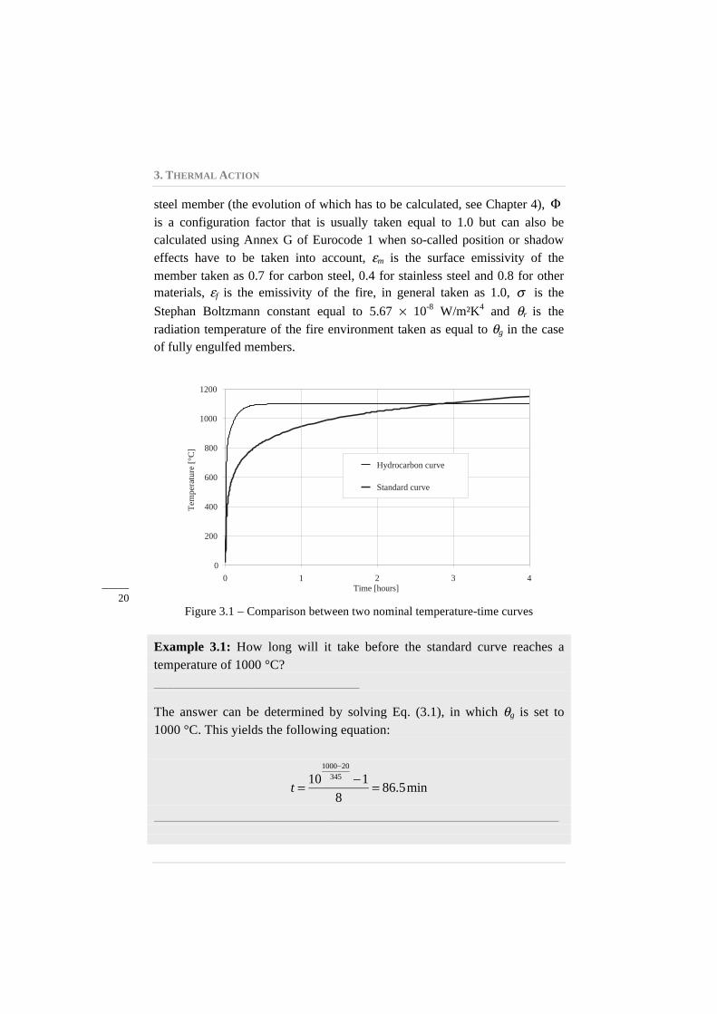
The standard and the hydrocarbon curves are compared in Fig. 3.1. It
shows that the hydrocarbon curve increases very quickly and reaches a constant value of 1100 °C after half an hour, whereas the standard curve increases more progressively but keeps on increasing with time.
When the environment is represented by a gas temperature, as is the case for nominal curves, Eq. (3.4) should be used to model the heat flux at the surface of a steel element.
h•
net = α c θg −θm( ) + Φεm ε f σ θr + 273( )4 − θm + 273( )4⎡⎣⎢
⎤⎦⎥
(3.4) where αc is the coefficient of convection which is taken as 25 W/m²K for the standard or the external fire curve and 50 W/m²K for the hydrocarbon curve, θg is the gas temperature in the vicinity of the surface either calculated from Eqs. (3.1), (3.2) or (3.3) or taken as 20 °C, θm is the surface temperature of the
3. THERMAL ACTION
_____ 20
steel member (the evolution of which has to be calculated, see Chapter 4), Φ is a configuration factor that is usually taken equal to 1.0 but can also be calculated using Annex G of Eurocode 1 when so-called position or shadow effects have to be taken into account, εm is the surface emissivity of the member taken as 0.7 for carbon steel, 0.4 for stainless steel and 0.8 for other materials, εf is the emissivity of the fire, in general taken as 1.0, σ is the Stephan Boltzmann constant equal to 5.67 × 10⁻⁸ W/m²K4 and θr is the radiation temperature of the fire environment taken as equal to θg in the case of fully engulfed members.
Figure 3.1 − Comparison between two nominal temperature-time curves
Example 3.1: How long will it take before the standard curve reaches a temperature of 1000 °C? _______________________________ The answer can be determined by solving Eq. (3.1), in which θg is set to 1000 °C. This yields the following equation:
t = 10
1000−20345 −18
= 86.5min
_____________________________________________________________
0
200
400
600
800
1000
1200
0 1 2 3 4Time [hours]
Tem
pera
ture
[°C
]
Hydrocarbon curve
Standard curve

3.3. PARAMETRIC TEMPERATURE-TIME CURVES
_____ 21
Example 3.2: Using the international system of units, write a procedure that returns the value of the hydrocarbon time-temperature curve for a given time. _______________________________
Procedure hydrocarbon(time,temperature)
c input time time in seconds
c intermediate time_m time in minutes
c temp_c temperature in degrees Celsius
c output temperature temperature in degrees Kelvin
Implicit none
Real: time, time_m, temp_c, temperature
time_m = time/60.
temp_c=20.+1080.*(1-0.325*exp(-0.167*time_m)-0.675*exp(-2.5*time_m))
temperature = temp_c +275.15
end procedure
3.3. PARAMETRIC TEMPERATURE-TIME CURVES Parametric temperature-time curves are analytical functions that give
the evolution of the gas temperature in a compartment as a function of time, based on parameters that represent the most important physical phenomena that influence the development of a compartment fire. Such a parametric curve is described in Annex A of Eurocode 1. It is valid for fire compartments up to 500 m² of floor area, without openings in the roof and for a maximum compartment height of 4 meters.
The three parameters that describe the curve are: 1) A parameter b which accounts for the thermal properties of the enclosure. It is related to the faculty of the boundaries of the compartment (walls, floor and ceiling) to absorb part of the energy released by the fire. It is calculated using Eq. (3.5) when the walls are made of a single material: b = cρλ (3.5) where c is the specific heat of the material forming the boundaries in J/kgK, ρ is the density of the material, in kg/m³, and λ is the thermal conductivity of the material, in W/mK. Table of the Annex A.9 gives the values of these properties for some enclosure surface materials.

3. THERMAL ACTION
_____ 22
As a simplification, these three properties may be taken at room temperature.
When different parts of the walls, the floor or the ceiling are made from different materials, a global value is calculated for the parameter b of the compartment by factoring the value of each part with respect to its area (openings not included), see Eq. (3.6).
b =
biAi∑Ai∑ (3.6)
where bi is the value of the factor for part i and Ai is the area of part i, openings not included.
When a surface is made of different layers of material, only the value b of the material of the innermost layer is considered, provided this value is lower than the value of the second layer of material. If the b value of the inner layer is higher than the b value of the second layer, then the b value of the inner layer may be used if this layer is thick; if this layer is thin, the influence of the second layer is also taken into account following the procedure given by Eq. (A.4) in the Eurocode.
The parameter b should have a value between 100 and 2200 J/m²s1/2K. The parameter b is based on the theory of heat penetration by conduction
in a semi-infinite medium. In a wall made of two layers of gypsum board separated by a cavity filled with air, for example, applying the equations of the Eurocode with the values of c, ρ and λ of the air would not be correct because heat travels by radiation and not by conduction in the air cavity. Similarly, it would not be correct to apply this model for a wall made of a thin steel sheet, in an industrial building for example. This model would be valid for steel only if the steel wall has infinite thickness, which is not practical (furthermore b for steel is around 13400, which is in excess of the admissible value of 2200). 2) A parameter O that accounts for the openings in the vertical walls. Higher values of this parameter mean more ventilation for the compartment. The value of this parameter has to be in the range 0.02 to 0.20 for the model of the Eurocode to be applicable. If a single rectangular opening is present in the compartment, the opening factor is calculated using Eq. (3.7). This equation has been derived from the integration of the Bernoulli equation for a pressure differential between the outside and the inside of the compartment that varies linearly as a function of the vertical position.

3.3. PARAMETRIC TEMPERATURE-TIME CURVES
_____ 23
O = Av h At (3.7)
where Av is the area of the opening, h is the height of the opening and At is the total area of the enclosure (walls, ceiling and floor), including the openings.
Eq. (3.7) shows that, for a given area, a vertically oriented opening is more efficient in venting the compartment than a horizontally oriented opening. When several rectangular openings are present in the compartment, the opening factor is calculated from Eq. (3.8).
O = Av heq At (3.8)
where Av is the total area of the vertical openings, heq is the averaged height of the window openings, calculated from Eq. (3.9).
heq = Avihi
i∑ Av (3.9)
3) The last parameter is the design fire load density related to the total area of the enclosure qt,d: floor, ceiling and walls, openings included. Annex E of Eurocode 1 allows determining the design value related to the floor area qf,d on the basis of the type of occupation of the compartment and the presence of active fire protection measures. Both values are related by Eq. (3.10).
qt ,d = qf ,d Af At (3.10)
where Af is the floor area and At is the total area of the enclosure.
The model is valid for values of qt,d between 50 and 1000 MJ/m². Application of the model starts by calculating an expansion coefficient
Γ from Eq. (3.11).
Γ = O 0.04
b 1160⎛⎝⎜
⎞⎠⎟
2
(3.11)
The evolution of temperature during the heating phase is given by Eq. (3.12) as a function of an expanded time t* given by Eq. (3.13).
θg = 20 + 1325 1− 0.324e−0.2t* − 0.204e−1.7t* − 0.472e−19t*( ) (3.12)
t* = Γ t (3.13)
where t is the time in hours.

3. THERMAL ACTION
_____ 24
The curve that can be plot from Eq. (3.12) as a function of t* is very close to the standard temperature-time curve. Eq. (3.13) shows that, when Γ is greater than 11, the temperature increase as a function of the real time t is faster than for lower values of Γ.
The duration of the heating phase tmax is given, in hours, by Eq. (3.14). tmax = 0.0002qt ,d O (3.14)
This value has to be compared with a limit value tlim that depends on the growth rate associated to the occupancy of the compartment, see Table (3.1).
Table 3.1 − Values of tlim as a function of the growth rate
Growth rate tlim in minutes tlim in hours
Slow (transport (public space)) 25 0.417
Medium (dwelling, hospital room, hotel room, office, classroom of a school) 20 0.333
Fast (library, shopping centre, theatre/cinema) 15 0.250
The comparison between the value calculated for tmax and the value of
tlim can lead to two different situations:
− Either tlim ≤ tmax and the fire is ventilation controlled. The procedure for this situation is explained below. The value of the gas temperature at the end of the heating phase, θmax, is calculated by substituting the value of tmax for t in Eq. (3.13) and (3.12). The expanded time that corresponds to the maximum time is calculated from Eq. (3.15).
tmax
* = Γ tmax (3.15) The time-temperature in the cooling phase is given by:
θg = θmax −625 t* − tmax
*( ) for tmax* ≤0.5 (3.16a)
θg = θmax −250 3− tmax
*( ) t* − tmax*( ) for 0.5 < tmax
* <2.0 (3.16b)
θg = θmax −250 t* − tmax
*( ) for 2.0≤ tmax* (3.16c)
1 Highly ventilated compartments or compartments with lightweight walls

3.3. PARAMETRIC TEMPERATURE-TIME CURVES
_____ 25
− Or tmax < tlim and the fire is fuel controlled. The procedure for this situation is explained below:
Eq. (3.17) is used instead of Eq. (3.13) to compute the evolution of the temperature during the heating phase.
t
* = Γlim t (3.17)
with
Γlim =
Olim 0.04b 1160
⎛⎝⎜
⎞⎠⎟
2
(3.18)
and Olim = 0.0001qt,d tlim (3.19)
If O > 0.04 and qt,d < 75 and b < 1160, then Γlim in Eq. (3.18) has to be multiplied for the factor k given by Eq. (3.20).
k = 1+ O − 0.04
0.04⎛⎝⎜
⎞⎠⎟
qt ,d −7575
⎛
⎝⎜⎞
⎠⎟1160− b1160
⎛⎝⎜
⎞⎠⎟
(3.20)
The expanded time that corresponds to the time of maximum temperature is calculated from Eq. (3.21). tmax
* = Γlim tlim (3.21) The value of the gas temperature at the end of the heating phase, θmax, is calculated by substituting the value of t*max for t* in Eq. (3.12). The time-temperature in the cooling phase is given by:
θg = θmax −625 t* − Γ tlim( ) for tmax
* ≤0.5 (3.22a)
θg = θmax −250 3− tmax
*( ) t* − Γ tlim( ) for 0.5 < tmax* <2.0 (3.22b)
θg = θmax −250 t* − Γ tlim( ) for 2.0≤ tmax
* (3.22c)
When applying Eq. (3.22), t* and t*max are calculated from Eqs. (3.13) and (3.15), and not from Eqs. (3.17) and (3.21).
It has to be noted that there is a discontinuity in the model at the transition from a fuel controlled fire to a ventilation controlled fire, because of the different factors being present in Eq. (3.14) and Eq. (3.19). An infinitely
3. THERMAL ACTION
_____ 26
small variation of a parameter can produce two time-temperature curves that are not close to each other. In other words, when tmax is exactly equal to tlim, the equations for a ventilation controlled fire lead to a fire curve that is different from the one obtained by the equations of a fuel controlled fire.
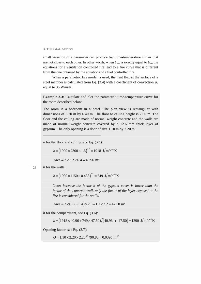
When a parametric fire model is used, the heat flux at the surface of a steel member is calculated from Eq. (3.4) with a coefficient of convection αc equal to 35 W/m²K. Example 3.3: Calculate and plot the parametric time-temperature curve for the room described below.
The room is a bedroom in a hotel. The plan view is rectangular with dimensions of 3.20 m by 6.40 m. The floor to ceiling height is 2.60 m. The floor and the ceiling are made of normal weight concrete and the walls are made of normal weight concrete covered by a 12.6 mm thick layer of gypsum. The only opening is a door of size 1.10 m by 2.20 m. _______________________________ b for the floor and ceiling, see Eq. (3.5): b = 1000× 2300×1.6( )0.5 = 1918 J m2s0.5K Area = 2× 3.2× 6.4 = 40.96 m2 b for the walls: b = 1000×1150× 0.488( )0.5 = 749 J m2s0.5K Note: because the factor b of the gypsum cover is lower than the
factor of the concrete wall, only the factor of the layer exposed to the fire is considered for the walls.
Area = 2× 3.2+ 6.4( )× 2.6 –1.1× 2.2 = 47.50 m2 b for the compartment, see Eq. (3.6): b = 1918× 40.96 +749× 47.50( ) 40.96 + 47.50( ) = 1290 J m2s0.5K Opening factor, see Eq. (3.7): O = 1.10× 2.20× 2.200.5 90.88 = 0.0395 m0.5

3.3. PARAMETRIC TEMPERATURE-TIME CURVES
_____ 27
Expansion coefficient, see Eq. (3.11):
Γ = 0.0395 0.04( ) 1290 1160( )( )2 = 0.788
Note: a value of Γ lower than 1.0 means that the fire curve will increase more slowly than the standard time-temperature curve.
Design fire load, see Eq. (3.10): table E.4 of Eurocode 1 gives for hotels a value of qf,k equal to 377 MJ/m². Assuming that the influence of active measures is not taken into account, this leads to qf,d = qf,k = 377 MJ/m². A combustion factor could be taken as m = 0.8 if the fire load is known to be cellulosic. A value of the factor m =1.0 was nevertheless considered here. qt ,d = 377 × 3.2× 6.4( ) 90.88 = 84.96 MJ m2 Duration of the heating phase, see Eq. (3.14): tmax = 0.0002× 84.96 0.0395 = 0.43 hour 26 min.( ). Limit value of time, see table 3.1: tlim = 0.333 hour Because tlim < tmax, the fire is ventilation controlled. Temperature at the end of the heating phase, see Eqs. (3.15) and (3.12): t*max = 0.7885×0.43 = 0.339 hour
θmax = 20 + 1325 1− 0.324e−0.2×0.339 − 0.204e−1.7×0.339 − 0.472e−19×0.339( )
θmax = 791 ºC . Time at the end of the cooling phase, see Eq. (3.16a): t
*20 = 791− 20( ) 625+ 0.339 = 1.573 hours
t20 = 1.573 0.7885 = 1.995 hours 120 min.( ) The complete time-temperature curve is show as a continuous line in Fig. 3.2. _____________________________________________________________

3. THERMAL ACTION
_____ 28
Example 3.4: Calculate and plot the parametric time-temperature for the room of example 3.3 if, in addition to the door, a window (2 m wide and 1 m high) is also open. _______________________________
b = 1918× 40.96 +749× 45.50( ) 40.96 + 45.50( ) = 1303 J/m2s0.5K,
see example 3.3 with a reduction of 2 m² for the area of the walls.
qt ,d = 84.96 MJ m2 , see example 3.3.
Opening factor, see Eq. (3.8) and (3.9):
heq = 1.1× 2.2× 2.2+1.0× 2.0×1.0( ) 1.1× 2.2+1.0× 2.0( ) = 1.657 m
O = 1.1× 2.2+1.0× 2.0( )×1.6570.5 90.88 = 0.0626 m1/2
Expansion coefficient, see Eq. (3.11):
Γ = 0.0626 0.04( ) 1303 /1160( )( )2 = 1.94
Duration of the heating phase, see Eq. (3.14):
tmax = 0.0002× 84.96 0.0626 = 0.27 hour 16 min.( ).
tlim = 0.333 hour
Because tmax < tlim, the fire is fuel controlled.
Olim = 0.0001× 84.96 0.333 = 0.0255 m1/2 , see Eq. 3.19.
Γlim = 0.0255 0.04( ) 1303 1160( )( )2 = 0.322
Temperature at the end of the heating phase, see Eq. (3.21) and (3.12):
t*max = 0.322×0.333 = 0.107 hour.
Note: this value is used to calculate the maximum temperature, at the end of the heating phase.
θmax = 20 + 1325 1− 0.324e−0.2×0.107 − 0.204e−1.7×0.107 − 0.472e−19×0.107( )
θmax = 618°C
Time at the end of the cooling phase:
t*max = 1.94 × 0.27 = 0.54 hour, see Eq. (3.15)

3.4. ZONE MODELS
_____ 29
Note: this value is used to calculate the slope during the cooling down phase.
Slope of the cooling down phase: 250 (3 - 0.54) = 615 °C/hour, see Eq.(3.22b)
t*20 = 618− 20( ) 615+ 0.333×1.94 = 1.618 hours
t20 = 1.618 1.94 = 0.834 hours 50 min.( )
The complete time-temperature curve is show as a dotted line in Fig. 3.2.
Figure 3.2 − Examples of parametric time-temperature curves
3.4. ZONE MODELS
Zone models are models that can be used to compute the development of the temperature in the fire compartment1 on the basis of differential equations expressing mass balance and energy balance equilibrium.
The main parameters that influence the development of the temperature are the same as those used for parametric fire models.
The openings in the boundaries play a crucial role because they provide the air that feeds the fire and because they can vent the compartment. But, whereas all the openings are represented by a single lumped parameter O in parametric models, each individual opening can be 1 And, for multiroom models, also in the adjacent compartments.
0
100
200
300
400
500
600
700
800
900
0 30 60 90 120 150Time [min.]
Tem
pera
ture
[°C]
Example 3.3
Example 3.4
BESTELLSCHEIN
Liefer- und Rechnungsanschrift: �privat �geschäftlich
Vertrauensgarantie: Dieser Auftrag kann innerhalb von zwei Wochen beim Verlag Ernst & Sohn, Wiley-VCH, Boschstr. 12, D-69469 Weinheim, schriftlich widerrufen werden.
Datum / Unterschrift *€-Preise gelten ausschließlich in Deutschland. Alle Preise enthalten die gesetzliche Mehrwertsteuer. Die Lieferung erfolgt zuzüglich Versandkosten. Es gelten die Lieferungs- und Zahlungsbedingungen des Verlages. Irrtum und Änderungen vorbehalten. Stand: Mai 2017 (homepage_Probekapitel)
Stück Bestell-Nr.: Titel Preis* €
978-3-433-03143-8 Fire Design of Steel Structures 2nd Edition 70,-
909538 Gesamtverzeichnis Ernst & Sohn 2016/2017 kostenlos
Monatlicher E-Mail-Newsletter: Anmeldung unter www.ernst-und-sohn.de/newsletter
Firma
Ansprechpartner Telefon
UST-ID Nr. / VAT-ID No. Fax
Straße//Nr. E-Mail
Land - PLZ Ort
Wilhelm Ernst & Sohn Verlag für Architektur und technische Wissenschaften GmbH & Co. KG Rotherstraße 21, 10245 Berlin Deutschland www.ernst-und-sohn.de


