Norfolk® and Tasman® retaining walls are a proven segmental block system designed and manufactured in Australia. Both systems have undergone extensive testing by the most up-to-date test facility in Australia and the results achieved are equal or better than most products designed in Australia or foreign countries.The aesthetic design and colour selection available ensures you not only get a retaining wall system designed for Australian conditions but a system that has the beauty to blend in any landscape environment.Professional engineers and designers prefer the qualities both systems have.• Positive connection, no pins or plastic connectors
that may or may not be used. • Snug fitting connections, very little movement once
blocks are placed on each other.• A professionally designed software package that
engineers can use to verify that their designs comply to Australian Standards.
Due to the success of Tasman® and Norfolk® segmental retaining wall systems, there have been several attempts to copy these systems but, as with most copies, they do not compare well because they cannot duplicate the unique, protected connection method of both Tasman® and Norfolk®When you choose either system you can be confident you will receive the best Australian designed segmental retaining wall system that is superior in quality, design and aesthetics of any local or overseas product.
3
Tasman® and Norfolk® Retaining Wall Evaluation and Installation GuideThis installation guide demonstrates the basics on how to construct
A. Segmental Concrete Gravity Retaining Walls up to 900mm high (Gravity)
B. Segmental Concrete Reinforced Soil Retaining Walls over 1 metre high (Reinforced)
C. Segmental Concrete Gravity Retaining Walls with No-fines Concrete over 1 metre high (No-fines Concrete)
This is a guide only, to help determine whether a gravity, soil reinforced or no-fines concrete retaining wall is the most appropriate for your situation, and the preparation necessary to achieve the end result.
This guide is not a design manual for soil reinforced or no-fines concrete retaining walls.
The information provided in no way replaces the services of professional consultants on a particular project. No liability can therefore be accepted by Baines Masonry.
STEP 1. Wall Height: Determine the maximum wall height. (see figure 1)
Wal
l Hei
ght
Figure 1. Maximum Wall Height
STEP 2. Decide on
A. Gravity retaining wall
B. Soil reinforced retaining wall
C. No-fines concrete retaining wall
A. Segmental Concrete Gravity Retaining Wall.
There are two types of gravity retaining walls: Type A1 Norfolk® which can be constructed up to 900mm high and Type A2 Tasman® which can be constructed up to 660mm high for straight walls and 860mm for serpentine walls.
Tasman® and Norfolk® Retaining Wall Evaluation and Installation Guide
4
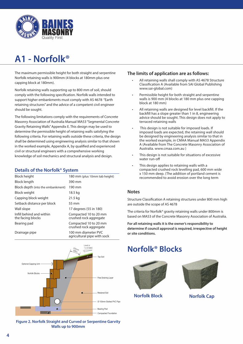
The maximum permissible height for both straight and serpentine Norfolk retaining walls is 900mm (4 blocks at 180mm plus one capping block at 180mm).
Norfolk retaining walls supporting up to 800 mm of soil, should comply with the following specification. Norfolk walls intended to support higher embankments must comply with AS 4678 “Earth retaining structures” and the advice of a competent civil engineer should be sought.
The following limitations comply with the requirements of Concrete Masonry Association of Australia Manual MA53 “Segmental Concrete Gravity Retaining Walls” Appendix E. This design may be used to determine the permissible height of retaining walls satisfying the following criteria. For retaining walls outside these criteria, the design shall be determined using engineering analysis similar to that shown in the worked example, Appendix A, by qualified and experienced civil or structural engineers with a comprehensive working knowledge of soil mechanics and structural analysis and design.
Details of the Norfolk® SystemBlock heightBlock lengthBlock depth (into the embankment)
Block weightCapping block weightSetback distance per blockWall slopeInfill behind and within the facing blocksBearing pad Drainage pipe
180 mm (plus 10mm tab height)
390 mm190 mm18.5 kg21.5 kg55 mm17 degrees (55 in 180)Compacted 10 to 20 mm crushed rock aggregateCompacted 10 to 20 mm crushed rock aggregate100 mm diameter PVC agricultural pipe with sock
Bearing Pad
Compacted Foundation
Retained Soil
Ø 100mm Slotted PVC Pipe
Free Draining Layer
Top Soil
Optional Capping Unit
Norfolk Blocks
1
Level or1 in 8 MAX200mm(MIN.)
The limits of application are as follows:• All retaining walls shall comply with AS 4678 Structure
Classification A (Available from SAI Global Publishing www.sai-global.com)
• Permissible height for both straight and serpentine walls is 900 mm (4 blocks at 180 mm plus one capping block at 180 mm)
• All retaining walls are designed for level backfill. If the backfill has a slope greater than 1 in 8, engineering advice should be sought. This design does not apply to terraced retaining walls
• This design is not suitable for imposed loads. If imposed loads are expected, the retaining wall should be designed by engineering analysis similar to that in the worked example, in CMAA Manual MA53 Appendix A (Available from The Concrete Masonry Association of Australia. www.cmaa.com.au )
• This design is not suitable for situations of excessive water run-off
• This design applies to retaining walls with a compacted crushed rock levelling pad, 600 mm wide x 150 mm deep. (The addition of portland cement is recommended to avoid erosion over the long term
NotesStructure Classification A retaining structures under 800 mm high are outside the scope of AS 4678
The criteria for Norfolk® gravity retaining walls under 800mm is based on MA53 of the Concrete Masonry Association of Australia.
For all retaining walls it is the owner’s responsibility to determine if council approval is required, irrespective of height or site conditions.
Figure 2. Norfolk Straight and Curved or Serpentine Garvity Walls up to 900mm
A1 - Norfolk®
Norfolk® Blocks
Norfolk Block Norfolk Cap
5
Bearing Pad
Compacted Foundation
Back�ll / Retained Soil
Ø 100mm AG-Pipe
Drainage Layer
Top Soil
Optional Capping Unit
Tasman Blocks
200mm(MIN.)
Compacted Clay
Geotextile
Figure 3 Tasman Curved and Serpentine Gravity Retaining Walls up to 860mm High
The limits of application are as follows:• All retaining walls shall comply with AS 4678
Structure Classification A (Available from SAI Global Publishing www.sai-global.com/)
• Permissible height for straight walls is 660mm (three courses and one cap) and serpentine walls is 860mm (four courses and one cap)
• All retaining walls are designed for level backfill. If the backfill has a slope greater than 1 in 8, engineering advice should be sought. This design does not apply to terraced retaining walls.
• This design is not suitable for imposed loads. If imposed loads are expected, the retaining wall should be designed by engineering analysis similar to that in the worked example, in CMAA Manual MA53 Appendix A (Available from The Concrete Masonry Association of Australia. www.cmaa.com.au )
• This design is not suitable for situations with excessive water run-off.
• This design applies to retaining walls with a compacted crushed rock levelling pad, 600 mm wide x 150 mm deep. (The addition of portland cement is recommended to avoid erosion over the long term
NotesStructure Classification A retaining structures under 800 mm high are outside the scope of AS 4678
The criteria for Tasman® gravity retaining walls is based on MA53 of the Concrete Masonry Association of Australia.
For all retaining walls it is the owner’s responsibility to determine if council approval is required, irrespective of height or site conditions.
Bearing Pad
Compacted Foundation
Back�ll / Retained Soil
Ø 100mm AG-Pipe
Drainage Layer
Top Soil
Optional Capping Unit
Tasman Blocks
200mm(MIN.)
Geotextile
Figure 4 Tasman Straight Gravity Retaining Walls up to 660mm High
The maximum permissible height for straight Tasman retaining walls is 660mm (three courses and one cap) and serpentine Tasman retaining walls is 860mm (four courses and on cap).
Tasman walls intended to support higher embankments must comply with AS 4678 “Earth retaining structures” and the advice of a competent civil engineer should be sought.
The following limitations comply with the requirements of Concrete Masonry Association of Australia Manual MA53 “Segmental Concrete Gravity Retaining Walls” Appendix E. This design may be used to determine the permissible height of retaining walls satisfying the following criteria. For retaining walls outside these criteria, the design shall be determined using engineering analysis similar to that shown in the worked example, Appendix A, by qualified and experienced civil or structural engineers with a comprehensive working knowledge of soil mechanics and structural analysis and design.
Details of the Tasman® System
Block heightBlock lengthBlock depth (into the embankment)
Block weightCapping block weightSetback distance per blockWall slopeInfill behind and within the facing blocksBearing pad
Drainage pipe
200 mm (plus 10 mm tab height)
390 mm225 mm23.5 kg12 kg10 mm3 degrees (10 in 225)Compacted 10 to 20 mm crushed rock aggregateCompacted 10 to 20 mm crushed rock aggregate 100 mm diameter PVC agricultural pipe with sock
A2 - Tasman®
6
Step 1 Check ComplianceCheck with your local council to ensure all local Building Codes are complied with.
Step 2 FoundationThe foundation material shall be compacted by several passes of a mechanical plate vibrator. Where there are significant variations of foundation material or compaction, soft spots, or where there is ponding of ground water, the material shall be removed, replaced and compacted in layers not exceeding
150 mm. Trenches shall be dewatered and cleaned prior to construction, such that no softened or loosened material remains.
Step 3 Bearing PadThe facing shall be built on a bearing pad, not less than 150 mm thick, consisting of one of the following options:
• Compacted crushed rock, well-graded and of low plasticity (without clay content), compacted by a plate vibrator;
• Cement-stabilized crushed rock, with an additional 5% by mass of GP Portland cement thoroughly mixed,
moistened and compacted by a plate vibrator; or
• Lean-mix concrete with a compressive strength of not less than 15 MPa.
Step 4 First CourseSpread 25mm of metal dust with an additional 5% by mass of GP Portland cement over the compacted base.
The first course is now bedded into the metal dust. The use of a level and string line is recommended to ensure the first course is laid correctly. Ensure each block is also well filled with free-draining material. (eg crushed rock aggregate / blue metal).
Step 5 Drainage and BackfillPlace 100 mm diameter PVC agricultural pipe with sock behind the wall, with a 1 in 100 fall. Backfill behind the courses of blocks to a width of approx. 200mm - 300mm using 10 - 20 mm free draining material (eg crushed rock aggregate / blue metal). Ensure each block is also well filled with free-draining material.
Step 6 Laying Additional CoursesLay the next course and subsequent courses to a string line following the same procedure, as outlined in step 4, cleaning the top of the blocks, filling the block cores and backfilling behind the blocks to a maximum of one block high, at a time. (As per step 5)
Step 7 Capping UnitsWhen a Norfolk capping block is laid as the final course no adhesive fixing is necessary.
If using a Tasman cap on either Norfolk or Tasman walls the capping block shall be fixed by Mason Bond adhesive
Note: The criteria for Norfolk and Tasman Gravity Retaining walls are based on MA53 of the Concrete Masonry Association of Australia
Installing Segmental Concrete Gravity Retaining Walls A1 and A2
Tasman Block Tasman Cap
Tasman® Blocks
7
Step 4 Bearing PadThe facing shall be built on a bearing pad, as per engineers advice, consisting of one of the following options:
• Compacted crushed rock, well-graded and of low plasticity (without clay content), compacted by a plate vibrator;
• Cement-stabilized crushed rock, with an additional 5% by mass of GP Portland cement thoroughly mixed, moistened and compacted by a plate vibrator; or
• Lean-mix concrete with a compressive strength of not less than 15 MPa.
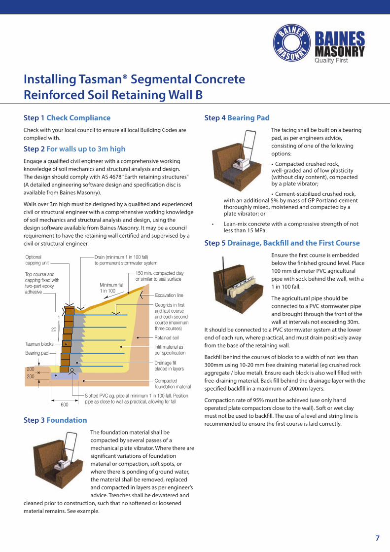
Step 5 Drainage, Backfill and the First CourseEnsure the first course is embedded below the finished ground level. Place 100 mm diameter PVC agricultural pipe with sock behind the wall, with a 1 in 100 fall.
The agricultural pipe should be connected to a PVC stormwater pipe and brought through the front of the wall at intervals not exceeding 30m.
It should be connected to a PVC stormwater system at the lower end of each run, where practical, and must drain positively away from the base of the retaining wall.
Backfill behind the courses of blocks to a width of not less than 300mm using 10-20 mm free draining material (eg crushed rock aggregate / blue metal). Ensure each block is also well filled with free-draining material. Back fill behind the drainage layer with the specified backfill in a maximum of 200mm layers.
Compaction rate of 95% must be achieved (use only hand operated plate compactors close to the wall). Soft or wet clay must not be used to backfill. The use of a level and string line is recommended to ensure the first course is laid correctly.
Installing Tasman® Segmental Concrete Reinforced Soil Retaining Wall B
Step 1 Check ComplianceCheck with your local council to ensure all local Building Codes are complied with.
Step 2 For walls up to 3m highEngage a qualified civil engineer with a comprehensive working knowledge of soil mechanics and structural analysis and design. The design should comply with AS 4678 “Earth retaining structures” (A detailed engineering software design and specification disc is available from Baines Masonry).
Walls over 3m high must be designed by a qualified and experienced civil or structural engineer with a comprehensive working knowledge of soil mechanics and structural analysis and design, using the design software available from Baines Masonry. It may be a council requirement to have the retaining wall certified and supervised by a civil or structural engineer.
Slotted PVC ag. pipe at minimum 1 in 100 fall. Positionpipe as close to wall as practical, allowing for fall
In�ll material asper speci�cation
Geogrids in �rstand last courseand each secondcourse (maximumthree courses)
Excavation line
600
Compactedfoundation material
Bearing pad
Tasman blocks
200200
Minimum fall1 in 100
150 min. compacted clayor similar to seal surface
Drain (minimum 1 in 100 fall)to permanent stormwater system
1
20
Retained soil
Drainage �llplaced in layers
Optionalcapping unit
Top course andcapping �xed withtwo-part epoxyadhesive
Step 3 FoundationThe foundation material shall be compacted by several passes of a mechanical plate vibrator. Where there are significant variations of foundation material or compaction, soft spots, or where there is ponding of ground water, the material shall be removed, replaced and compacted in layers as per engineer’s advice. Trenches shall be dewatered and
cleaned prior to construction, such that no softened or loosened material remains. See example.
8
Step 6 Laying GeogridClean any debris from the top of the block wall to ensure the next block and or the geogrid layer sits perfectly. Roll the geogrid perpendicular to the wall, pull tight, stake in place and cut to the required length. Ensure that the geogrid sits within 15mm of the face of the block, so that the purpose made connecting lugs can interlock. Butt join the geogrid along
the length of the wall. Place the next course on top of the geogrid.
Baines Masonry recommends and supplies Fortrac® Geogrid Manufactured by Huesker® Inc
Step 7 Laying Additional CoursesLay the next course and subsequent courses to a string line following the procedures outlined previously i.e. Clean any debris from the top of the block wall to ensure the next block and or the geogrid layer sits perfectly. Backfill behind the course of blocks to a width of not less than 300mm using 10-20 mm free
draining material (eg crushed rock aggregate / blue metal). Ensure each block is also well filled with free-draining material.
Back fill behind the drainage layer with the specified backfill in a maximum of 200mm layers.
Compaction rate of 95% must be achieved (use only hand operated plate compactors close to the wall). Soft or wet clay must not be used to backfill.
Step 8 CappingThe capping block shall be fixed by SRW Adhesive
Step 9 Surface DrainageThe whole of the disturbed fill surface should be sealed by at least 150mm of compacted clay and properly drained. Alternative means, such as bentonite layers or PVC membranes may be employed, provided they do not introduce potential slip planes into the surface material.
SRW Adhesive is a rapid-set polyurethane adhesive formulated to permanently bond concrete masonry block structures.
Fastest Set-Up Time on the Market with SRW Adhesive masonry adhesive instead of mortar and you’ll save TIME & MONEY.
BENEFITS • Fastest set-up time on the
market!
• High temperature adhesive suitable for firepits
• For use on dry or damp surfaces
• Premium, long lasting strength
• Interior/exterior use
• Specially formulated for use on construction and landscape projects
TM
Installing Tasman® Concrete Reinforced Soil Retaining Wall B
9
Step 1 Check ComplianceCheck with your local council to ensure all local Building Codes are complied with.
Step 2 For walls up to 3m high Engage a qualified civil engineer with a comprehensive working knowledge of soil mechanics and structural analysis and design. The design should comply with AS 4678 “Earth retaining structures” (A detailed engineering software design and specification disc is available from Baines Masonry)
Walls over 3m high must be designed by a qualified and experienced civil or structural engineer with a comprehensive working knowledge of soil mechanics and structural analysis and design, using the design software available from Baines Masonry. It may be a council requirement to have the retaining wall certified and supervised by a civil or structural engineer.
Slotted PVC ag. pipeat min. 1 in 100 fall
Excavation line
B*
Compactedfoundation material
Bearing pad
Tasman blocks
H*bp
2H*bp
Minimum fall1 in 100
150 min. compacted clayor similar to seal surface
Drain (min. 1 in 100 fall) topermanent stormwater system
1
20No-�nes concrete
Retained soil
Optional capping unit
Specification of No-fines Concrete infill
No-fines concrete shall be free-draining, allowing water to pass readily through it to the drainage system.
No-fines concrete shall have a bulk density not less than 1800kg/m³ and an aggregate to GP cement ratio not greater than 6:1 (by volume).
Step 3 FoundationThe foundation material shall be compacted by several passes of a mechanical plate vibrator. Where there are significant variations of foundation material or compaction soft spots, or where there is ponding of ground water, the material shall be removed, replaced and compacted in layers as per engineer’s advice. Trenches shall
be dewatered and cleaned prior to construction, such that no softened or loosened material remains. See example.
Step 4 Bearing Pad The facing shall be built on a bearing pad, as per engineers advice, consisting of one of the following options:
• Compacted crushed rock, well-graded and of low plasticity (without clay content), compacted by a plate vibrator;
• Cement-stabilized crushed rock, with an additional 5% by mass of GP Portland cement thoroughly mixed, moistened and compacted by a plate vibrator; or
• Lean-mix concrete with a compressive strength of not less than 15 MPa.
Step 5 Drainage, Backfill and the First CoursePlace 100 mm diameter PVC agricultural pipe with sock behind the wall, with a 1 in 100 fall.
The agricultural pipe should be connected to a PVC stormwater pipe and brought through the front of the wall at intervals not exceeding 30m. It should be connected to a PVC
stormwater system at the lower end of each run, where practical, and must drain positively away from the base of the retaining wall.
Backfill behind the course of blocks to a width of not less than 300mm using no-fines concrete. Ensure each block is also well filled with no-fines concrete. Back fill behind the drainage layer with the specified backfill in a maximum of 200mm layers.
Compaction rate of 95% must be achieved (use only hand operated plate compactors close to the wall). Soft or wet clay must not be used to backfill. The use of a level and string line is recommended to ensure the first course is laid correctly.
Step 6 Laying Additional CoursesLay the next course and subsequent courses to a string line following the procedures outlined previously i.e. Clean any debris from the top of the block wall to ensure the next block sits perfectly. Backfill behind the course of blocks to a width of not less than 300mm using no-fines concrete. Ensure each block is also well filled with no-fines concrete.
Back fill behind the drainage layer with the specified backfill in a maximum of 200mm layers.
Compaction rate of 95% must be achieved (use only hand operated plate compactors close to the wall). Soft or wet clay must not be used to backfill.
Step 7 CappingThe capping block shall be fixed by Mason Bond adhesive
Step 8 Surface DrainageThe whole of the disturbed fill surface should be sealed by at least 150mm of compacted clay and properly drained. Alternative means such as bentonite layers or PVC membranes may be employed, provided they do not introduce potential slip planes into the surface material.
Installing Tasman® No-fines Concrete Retaining Walls C
11
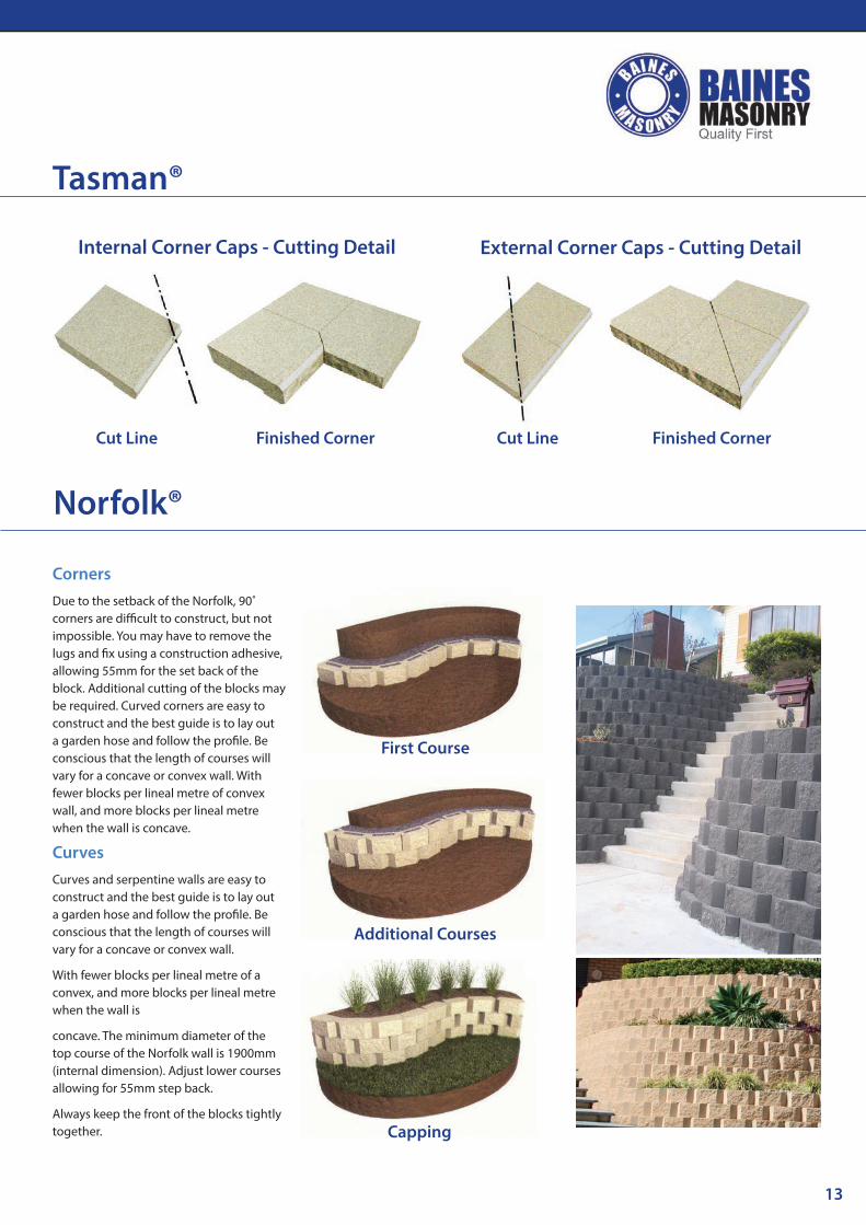
CurvesCurves and serpentine walls are easy to construct and the best guide is to lay out a garden hose and follow the profile. Be conscious that the length of courses will vary for a concave or convex wall. With fewer blocks per lineal metre of a convex, and more blocks per lineal metre when the wall is concave. For convex curved walls knock the back fin off the block with a hammer. For concave walls simply position blocks. The minimum radius for the top course of Tasman half blocks is 650mm and Tasman blocks is 1300mm. Adjust lower courses allowing for 10mm step back.
Always keep the front of the blocks tightly together.
CornersTasman corners are built by fixing the purpose made corner blocks alternately to each course using adhesive. Allowances should be made for a 10mm step back per course.
Lugs must be removed from the Tasman Blocks to ensure that the corner block fits evenly.
A maximum height of one metre is recommended when using corner blocks.
Curved corners is the preferred method of corner construction.
StepsSteps must be built according to the local building code, so always check with your local building authority for the minimum requirements before commencing.
Tasman®
First Course
Additional Courses
Capping
Prepare Surface
Install blocks
Capping
First Course
Additional Courses
Capping
12
Wall Step DownsStepping down a Tasman Wall can be easily achieved by using half corners and half caps.
All corners, half corners and caps must be fixed by SRW Adhesive.
Stepping down using a half corner
Stepping down using a half caps
Stepping down and returns
Stepping down planter box
Tasman®
13
CornersDue to the setback of the Norfolk, 90˚ corners are difficult to construct, but not impossible. You may have to remove the lugs and fix using a construction adhesive, allowing 55mm for the set back of the block. Additional cutting of the blocks may be required. Curved corners are easy to construct and the best guide is to lay out a garden hose and follow the profile. Be conscious that the length of courses will vary for a concave or convex wall. With fewer blocks per lineal metre of convex wall, and more blocks per lineal metre when the wall is concave.
CurvesCurves and serpentine walls are easy to construct and the best guide is to lay out a garden hose and follow the profile. Be conscious that the length of courses will vary for a concave or convex wall.
With fewer blocks per lineal metre of a convex, and more blocks per lineal metre when the wall is
concave. The minimum diameter of the top course of the Norfolk wall is 1900mm (internal dimension). Adjust lower courses allowing for 55mm step back.
Always keep the front of the blocks tightly together.
Gravity retaining walls depend on the weight of their mass to resist pressures from behind and will often have a slight batter set back, to improve stability by leaning back into the retained soil.
Soil Reinforced Retaining Walls
Soil reinforced retaining walls incorporate geogrids into the soil structure to create a segmental concrete reinforced soil structure. Such systems can be constructed several metres high and accommodate significant loads.
No-Fines Concrete Retaining Wall
No-fines concrete retaining walls use no-fines concrete as a mass behind the concrete facing units to reinforce the soil structure to create a segmental concrete reinforced soil structure. Such systems can be constructed several metres high and accommodate signifcant loads.
Serpentine Wall
The serpentine wall derives its name from its curving shape, which is in the form of a snake.
Geogrids
Layers of metal or plastic material, which when constructed in horizontal planes in a soil mass, strengthen the soil. The most common geogrids are open “mesh” consisting of polyester, high-density polyethene, polyproplene or steel.
Infill Material
The soil material, placed behind the retaining wall facing and strengthened by the geogrids.
Foundation
The natural soil or rock material under a retaining wall.
Bearing Pad
The pad the Tasman® or Norfolk® blocks are built on.
Drainage Fill
The crushed rock, gravel or similar material placed behind a retaining wall to convey groundwater away from the wall foundations. It is commonly used in conjunction with other drainage media, such as agricultural pipes.
15
ClientSite
Ph Fax
this drawing is indicative only and is not to scale unless otherwise stated
Date
16
Supplier:
Please see our full terms and conditions on our website www.bainesmasonry.com.au
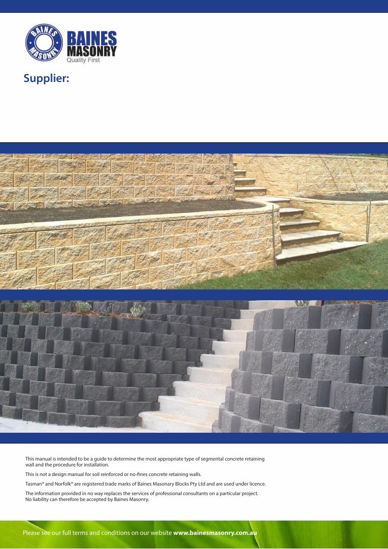
This manual is intended to be a guide to determine the most appropriate type of segmental concrete retaining wall and the procedure for installation.
This is not a design manual for soil reinforced or no-fines concrete retaining walls.
Tasman® and Norfolk® are registered trade marks of Baines Masonary Blocks Pty Ltd and are used under licence.
The information provided in no way replaces the services of professional consultants on a particular project. No liability can therefore be accepted by Baines Masonry.