51
Tube & Pipe Technical Catalog Tube & Pipe TMK Technical Catalog © 2014 OAO TMK. All rights reserved. Version 01.14.
| Date post: | 01-Sep-2018 |
| Category: |
Documents |
| Upload: | phungnguyet |
| View: | 214 times |
| Download: | 0 times |
Tube & Pipe
Technical Catalog
Tube
& P
ipe
TM
K
Tec
hnic
al C
atal
og
© 2014 OAO TMK. All rights reserved. Version 01.14.

1
Contents
2 About the Company4 TMK Facilities6 Sales Network9 Drill Pipe19 OCTG53 Line Pipe65 Anti-Corrosion Coating69 Process & Power Generation81 Mechanical Tube89 Structurals & Standard Pipe93 Semi-finished Steel Products96 Calculations & ConversionsContacts
The information presented herein is intended for use by industry professionals, using their own knowledge, experience and expertise. Although we have endeavored to provide accurate information and calculations, such information may be subject to change or correction, and OAO TMK and its affiliates take no responsibility for the reliance on or use of any information contained herein.
©2014 OAO TMK, all rights reserved
2 3
About the Company
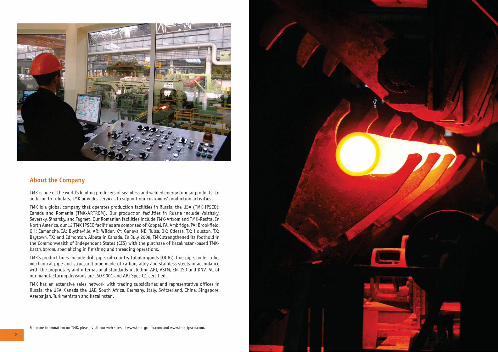
TMK is one of the world’s leading producers of seamless and welded energy tubular products. In addition to tubulars, TMK provides services to support our customers’ production activities.
TMK is a global company that operates production facilities in Russia, the USA (TMK IPSCO), Canada and Romania (TMK-ARTROM). Our production facilities in Russia include Volzhsky, Seversky, Sinarsky, and Tagmet. Our Romanian facilities include TMK-Artrom and TMK-Resita. In North America, our 12 TMK IPSCO facilities are comprised of Koppel, PA, Ambridge, PA; Brookfield, OH; Camanche, IA; Blytheville, AR; Wilder, KY; Geneva, NE; Tulsa, OK; Odessa, TX; Houston, TX; Baytown, TX; and Edmonton, Albeta in Canada. In July 2008, TMK strengthened its foothold in the Commonwealth of Independent States (CIS) with the purchase of Kazakhstan-based TMK-Kaztrubprom, specializing in finishing and threading operations.
TMK’s product lines include drill pipe, oil country tubular goods (OCTG), line pipe, boiler tube, mechanical pipe and structural pipe made of carbon, alloy and stainless steels in accordance with the proprietary and international standards including API, ASTM, EN, ISO and DNV. All of our manufacturing divisions are ISO 9001 and API Spec Q1 certified.
TMK has an extensive sales network with trading subsidiaries and representative offices in Russia, the USA, Canada the UAE, South Africa, Germany, Italy, Switzerland, China, Singapore, Azerbaijan, Turkmenistan and Kazakhstan.
For more information on TMK, please visit our web sites at www.tmk-group.com and www.tmk-ipsco.com.
4 5
RUSSIA
KAZAKHSTAN
UNITED STATES
ROMANIA
Headquarters
Pipe plantsFinishing mills Research & development
Steelmaking
TMK
Moscow
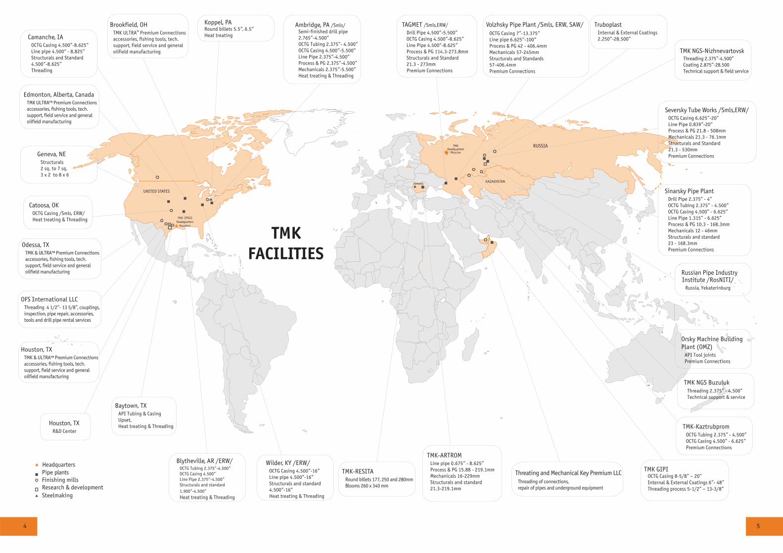
TMKFACILITIES
Camanche, IAOCTG Casing 4.500”-8.625”Line pipe 4.500“ - 8.825”Structurals and Standard4.500”-8.625”Threading
Geneva, NEStructurals2 sq. to 7 sq.3 x 2 to 8 x 6
Catoosa, OKOCTG Casing /Smls, ERW/Heat treating & Threading
Odessa, TXTMK & ULTRA™ Premium Connectionsaccessories, fishing tools, tech. support, field service and general oilfield manufacturing
Houston, TXTMK & ULTRA™ Premium Connectionsaccessories, fishing tools, tech. support, field service and general oilfield manufacturing
Baytown, TXAPI Tubing & CasingUpset, Heat treating & Threading
Blytheville, AR /ERW/OCTG Tubing 2.375”-4.500”OCTG Casing 4.500”Line Pipe 2.375“-4.500”Structurals and standard
1.900”-4.500” Heat treating & Threading
Wilder, KY /ERW/OCTG Casing 4.500”-16”Line pipe 4.500”-16”Structurals and standard4.500”-16”Heat treating & Threading
TMK-RESITARound billets 177, 250 and 280mmBlooms 260 x 340 mm
TMK-ARTROM Line pipe 0.675” - 8.625” Process & PG 15.88 - 219.1mmMechanicals 16-229mmStructurals and standard 21.3-219.1mm
TMK NGS BuzulukThreading 2.375” - 4.500”Technical support & service
Orsky Machine Building Plant (OMZ)
API Tool joints
Premium Connections
Russian Pipe IndustryInstitute /RosNITI/
Russia, Yekaterinburg
Sinarsky Pipe Plant Drill Pipe 2.375” - 4”OCTG Tubing 2.375” - 4.500”OCTG Casing 4.500” - 6.625”Line Pipe 1.315” - 6.625”Process & PG 10.3 - 168.3mmMechanicals 12 - 46mmStructurals and standard23 - 168.3mm
Premium Connections
Seversky Tube Works /Smls,ERW/OCTG Casing 6.625”-20”Line Pipe 0.839”-20”Process & PG 21.8 - 508mmMechanicals 21.3 - 76.1mmStructurals and Standard21.3 - 530mm
Premium Connections
TMK NGS-NizhnevartovskThreading 2.375”-4.500”Coating 2.875”-28.500Technical support & field service
TruboplastInternal & External Coatings2.250”-28.500”
Volzhsky Pipe Plant /Smls, ERW, SAW/
OCTG Casing 7”-13.375”Line pipe 6.625”-100”Process & PG 42 - 406.4mmMechanicals 57-245mmStructurals and Standards57-406.4mm
Premium Connections
TAGMET /Smls,ERW/
Drill Pipe 4.500”-5.500”OCTG Casing 4.500”-8.625”Line Pipe 4.500“-8.625”Process & PG 114.3-273.8mmStructurals and Standard21.3 - 273mm
Premium Connections
TMK-KaztrubpromOCTG Tubing 2.375” - 4.500”OCTG Casing 4.500” - 6.625”Premium Connections
Koppel, PARound billets 5.5”, 6.5”Heat treating
Ambridge, PA /Smls/Semi-finished drill pipe2.765”-4.500”OCTG Tubing 2.375”- 4.500”OCTG Casing 4.500”-5.500”Line Pipe 2.375”-4.500”Process & PG 2.375”-4.500”Mechanicals 2.375”-5.500”Heat treating & Threading
TMK IPSCO
Houston
Brookfield, OHTMK ULTRA
TM Premium Connections
accessories, fishing tools, tech.support, field service and generaloilfield manufacturing
Edmonton, Alberta, CanadaTMK ULTRA™ Premium Connectionsaccessories, fishing tools, tech. support, field service and general oilfield manufacturing
Houston, TX R&D Center
TMK GIPI OCTG Casing 8-5/8” – 20” Internal & External Coatings 6”- 48” Threading process 5-1/2” – 13-3/8”
Threating and Mechanical Key Premium LLC
Threading of connections,repair of pipes and underground equipment
OFS International LLCThreading 4 1/2”- 13 5/8”, couplings, inspection, pipe repair, accessories, tools and drill pipe rental services
Headquarters
Headquarters

6 7
Immermannstraße 65 c, 40210 Düsseldorf, GermanyTel: +49 (0) 211/91348830 Fax: +49 (0) 211/[email protected]
RUSSIA
KAZAKHSTAN
CHINA
UNITED STATES
GERMANY
SWITZERLAND
TURKMENISTAN
ITALY
UAE
SINGAPORE
HeadquartersRegions of shipmentsTMK sales offices
Cologne
Zurich
Lecco
Baku
Dubai
Ashgabat
Beijing
Astana
AZERBAIJAN
SALESNETWORK
TMK ChinaChina ZIP 100027, APT, 19 I48 Dongzhimenwai StreetDongcheng District BeijingTel + 86 10 84549581
TMK Global AG2, Bvld. Du Theatre 7,
CH-1211, Geneva, SwitzerlandTel + 41 22 818 64 [email protected]
TMK Europe GmbH
-
TMK-Kazakhstan20, Dostyk st., Astana, Kazakhstan, 01000 Tel: +7 (7172) 57-34-34, 57-85-32, Fax: +7 (7172) 57-85-35E-mail: [email protected]
TMK Italy S.R.L.Piazza Degli Affari 12,23900 Lecco, ItalyTel + 39 0341 365151
TMK TurkmenistanHotel Nebitchy 29 Archabil Shaely, 1939 Ashgabat, TurkmenistanTel + 99312 488798
TMK Singapore10 Anson Road #33-06AInternational Plaza, Singapore 079903Tel + 65 622 33 015
TMK Middle EastPO Box 293534Block. 5EA, Of. 119Dubai Airport Free ZoneUnited Arab EmiratesTel + 9714 [email protected]
TMK Azerbaijan22, Karabah street, Baku, AZ1008, AzerbaijanTel + 99412 4961918
INTERNATIONAL STATEOIL & GAS COMPANIES
OGDCLCNPCPETROVIETNAMONGCKUWAIT OIL COMPANY (KOC)NATIONAL IRANIAN OIL COMPANY (NIOC)SAUDI ARAMCOSYRIAN PETROLEUM COMPANY (SPC)SONATRACHTURKISH PETROLEUMGROUPEMENT BERKINESOCARKAZMUNAYGAZNEFTEGAZ OF UKRAINATURKMENNEFTEGAZUZBEKNEFTEGAZ
INTERNATIONAL INDEPENDENTOIL & GAS COMPANIES
SHELLEXXON MOBILCHEVRONTOTALAGIPOCCIDENTAL PETROLEUMWINTERSHALLSTATOILREPSOLANADARKO PETROLEUMOMVWOODSIDE PETROLEUM
MAERSK OILAL-FURAT PETROLEUM COMPANYPDOESHPETCOPETRO-CANADAANADARKO PETROLEUMAMERADA HESS
MAJOR EPC & OILFIELDDEVELOPMENT COMPANIES
SAIPEMTECHNIPSCHLUMBERGERHALLIBURTONKELLOGG , BROWN & ROOTPETROFACAMECPENSPEN GROUPBOTASENTERPOSE CONTRACTING
RUSSIAN OIL & GAS COMPANIES
GAZPROMTRANSNEFTLUKOILROSNEFTGAZPROMNEFTSURGUTNEFTEGAZTATNEFTTNK-BPRUSSNEFT
TMK’s Major Customers
Trade House TMK40, bld. 2a, Pokrovka StreetMoscow, 105062, RussiaTel + 7 495 775 76 00
ROMANIA
TMK-ARTROM Sales Office str. Draganesti 30, Slatina, Olt, 230119, Romania Tel: +40 249 43-68-62, 43-46-40 Fax: +40 249 43-43-30 [email protected]
TMK IPSCO U.S. Sales Office
10120 Houston Oaks Dr.
Houston, TX 77064 USA
Tel + 1 281 949 1023
Fax + 1 281 445 4040
TMK IPSCO Canada Sales Office
150 6-th Avenue SW#3000
Calgary, AB T2P 3Y7, Canada
Tel + 1 403 538 2182
Fax + 1 403 538 2183
Calgary
Cape Town
SOUTH AFRICA
TMK Africa Office 12002, Triagle House, 22Riebeek st, Central, Cape Town, South Africa 8001Tel.: +27 21 418 2066Fax: +27 21 418 [email protected]
TMK Uzbekistan
24 Oybek koch,
Toshkent sh, Uzbekistan, 00015
Tel.: +998 71 281-46-13
Fax: +998 71 281-46-14
TMK GIPI Gulf International Pipe Industry L.L.C. P.O. Box 1831, PC 130 Azaiba, Sultanate of Oman Tel.: +968 246 014 00, +968 268 270 00 Fax: +969 246 911 17 [email protected]
TMK IPSCO
HoustonHeadquarters
TMK
MoscowHeadquarters

8 9
Drill Pipe
TMK provides high quality drill pipe for the oil and gas industry. Drill pipe is produced at the Sinarsky plant (Russia), TAGMET (Russia) and green tube is manufactured at Ambridge (US). Weld-on tool joints are produced and delivered by OMZ (Russia), which is part of TMK Oilfield Services, certified by API Spec 7. Pipe sizes range from 2 3/8 up to 5 1/2 inches and can be produced in grades E75, X95, G105 and S135. Ambridge drill pipe can be produced as green tube for further finishing.
During production, all pipe undergoes required heat treatment and NDT inspection. TMK drill pipe can be produced to lengths both in Range 2 and Range 3. To prevent corrosion, each pipe is covered with a protective coating. Drill pipe connections are coated with an anti-corrosion thread compound and API composite thread protectors are applied. Delivery is carried out in strict accordance to API loading and transportation standards.
Drill Pipe Producers
Plant Location Products OD WT Grades
Sinarsky Pipe Plant /Russia/ Drill Pipe 2 3/8 - 4 0.280” - 0.449” E75, X95, G105, S135
TAGMET /Russia/ Drill Pipe 4 1/2 - 5 1/2 0.337” - 0.500” E75, X95, G105, S135
Ambridge /US/ Green Tube 2 3/8 - 5 1/2 0.362” - 0.474” E75, X95, G105, S135
10 11
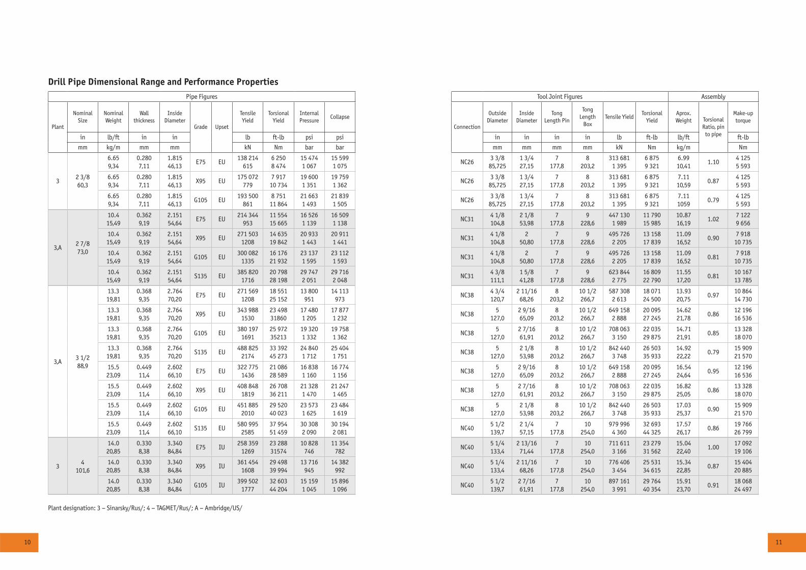
Drill Pipe Dimensional Range and Performance Properties
Pipe Figures Tool Joint Figures Assembly
Plant
Nominal Size
Nominal Weight
Wall thickness
Inside Diameter
Grade Upset
Tensile Yield
Torsional Yield
Internal Pressure
Collapse
Connection
Outside Diameter
Inside Diameter
Tong Length Pin
Tong Length
BoxTensile Yield
Torsional Yield
Aprox. Weight Torsional
Ratio, pin to pipe
Make-up torque
in lb/ft in in lb ft-lb psi psi in in in in lb ft-lb lb/ft ft-lb
mm kg/m mm mm kN Nm bar bar mm mm mm mm kN Nm kg/m Nm
32 3/860,3
6.659,34
0.2807,11
1.815 46,13
E75 EU138 214
6156 2508 474
15 4741 067
15 599 1 075
NC263 3/8
85,7251 3/4 27,15
7 177,8
8 203,2
313 681 1 395
6 875 9 321
6.99 10,41
1.104 125 5 593
6.659,34
0.2807,11
1.815 46,13
Õ95 EU175 072
7797 917
10 73419 600 1 351
19 759 1 362
NC263 3/8
85,7251 3/4 27,15
7 177,8
8 203,2
313 681 1 395
6 875 9 321
7.11 10,59
0.874 125 5 593
6.659,34
0.2807,11
1.815 46,13
G105 EU193 500
8618 751
11 86421 663 1 493
21 839 1 505
NC263 3/8
85,7251 3/4 27,15
7 177,8
8 203,2
313 681 1 395
6 875 9 321
7.11 1059
0.794 125 5 593
3,A2 7/873,0
10.415,49
0.3629,19
2.151 54,64
E75 EU214 344
95311 55415 665
16 526 1 139
16 509 1 138
NC314 1/8 104,8
2 1/8 53,98
7 177,8
9 228,6
447 130 1 989
11 790 15 985
10.87 16,19
1.027 122 9 656
10.415,49
0.3629,19
2.151 54,64
Õ95 EU271 503
120814 63519 842
20 933 1 443
20 911 1 441
NC314 1/8 104,8
2 50,80
7 177,8
9 228,6
495 726 2 205
13 158 17 839
11.09 16,52
0.907 918
10 735
10.415,49
0.3629,19
2.151 54,64
G105 EU300 082
133516 17621 932
23 137 1 595
23 112 1 593
NC314 1/8 104,8
2 50,80
7 177,8
9 228,6
495 726 2 205
13 158 17 839
11.09 16,52
0.817 918
10 735
10.415,49
0.3629,19
2.151 54,64
S135 EU385 820
171620 798 28 198
29 747 2 051
29 716 2 048
NC314 3/8 111,1
1 5/8 41,28
7 177,8
9 228,6
623 844 2 775
16 809 22 790
11.55 17,20
0.8110 167 13 785
3,A3 1/288,9
13.319,81
0.3689,35
2.764 70,20
E75 EU271 569
120818 551 25 152
13 800 951
14 113 973
NC384 3/4 120,7
2 11/16 68,26
8 203,2
10 1/2 266,7
587 308 2 613
18 071 24 500
13.93 20,75
0.9710 864 14 730
13.319,81
0.3689,35
2.764 70,20
Õ95 EU343 988
153023 498 31860
17 480 1 205
17 877 1 232
NC385
127,02 9/16 65,09
8 203,2
10 1/2 266,7
649 158 2 888
20 095 27 245
14.62 21,78
0.8612 196 16 536
13.319,81
0.3689,35
2.764 70,20
G105 EU380 197
169125 972 35213
19 320 1 332
19 758 1 362
NC385
127,02 7/16 61,91
8 203,2
10 1/2 266,7
708 063 3 150
22 035 29 875
14.71 21,91
0.8513 328 18 070
13.319,81
0.3689,35
2.764 70,20
S135 EU488 825
217433 392 45 273
24 840 1 712
25 404 1 751
NC385
127,02 1/8 53,98
8 203,2
10 1/2 266,7
842 440 3 748
26 503 35 933
14.92 22,22
0.7915 909 21 570
15.523,09
0.44911,4
2.602 66,10
E75 EU322 775
143621 086 28 589
16 838 1 160
16 774 1 156
NC385
127,02 9/16 65,09
8 203,2
10 1/2 266,7
649 158 2 888
20 095 27 245
16.54 24,64
0.9512 196 16 536
15.523,09
0.44911,4
2.602 66,10
Õ95 EU408 848
181926 708 36 211
21 328 1 470
21 247 1 465
NC385
127,02 7/16 61,91
8 203,2
10 1/2 266,7
708 063 3 150
22 035 29 875
16.82 25,05
0.8613 328 18 070
15.523,09
0.44911,4
2.602 66,10
G105 EU451 885
201029 520 40 023
23 573 1 625
23 484 1 619
NC385
127,02 1/8 53,98
8 203,2
10 1/2 266,7
842 440 3 748
26 503 35 933
17.03 25,37
0.9015 909 21 570
15.523,09
0.44911,4
2.602 66,10
S135 EU580 995
258537 954 51 459
30 308 2 090
30 194 2 081
NC405 1/2 139,7
2 1/4 57,15
7 177,8
10 254,0
979 996 4 360
32 693 44 325
17.57 26,17
0.8619 766 26 799
34
101,6
14.020,85
0.3308,38
3.340 84,84
E75 IU258 359
126923 288 31574
10 828 746
11 354 782
NC405 1/4 133,4
2 13/16 71,44
7 177,8
10 254,0
711 611 3 166
23 279 31 562
15.04 22,40
1.0017 092 19 106
14.020,85
0.3308,38
3.340 84,84
Õ95 IU361 454
160829 498 39 994
13 716 945
14 382 992
NC405 1/4 133,4
2 11/16 68,26
7 177,8
10 254,0
776 406 3 454
25 531 34 615
15.34 22,85
0.8715 404 20 885
14.020,85
0.3308,38
3.340 84,84
G105 IU399 502
177732 603 44 204
15 159 1 045
15 896 1 096
NC405 1/2 139,7
2 7/16 61,91
7 177,8
10 254,0
897 161 3 991
29 764 40 354
15.91 23,70
0.9118 068 24 497
Plant designation: 3 – Sinarsky/Rus/; 4 – TAGMET/Rus/; A – Ambridge/US/
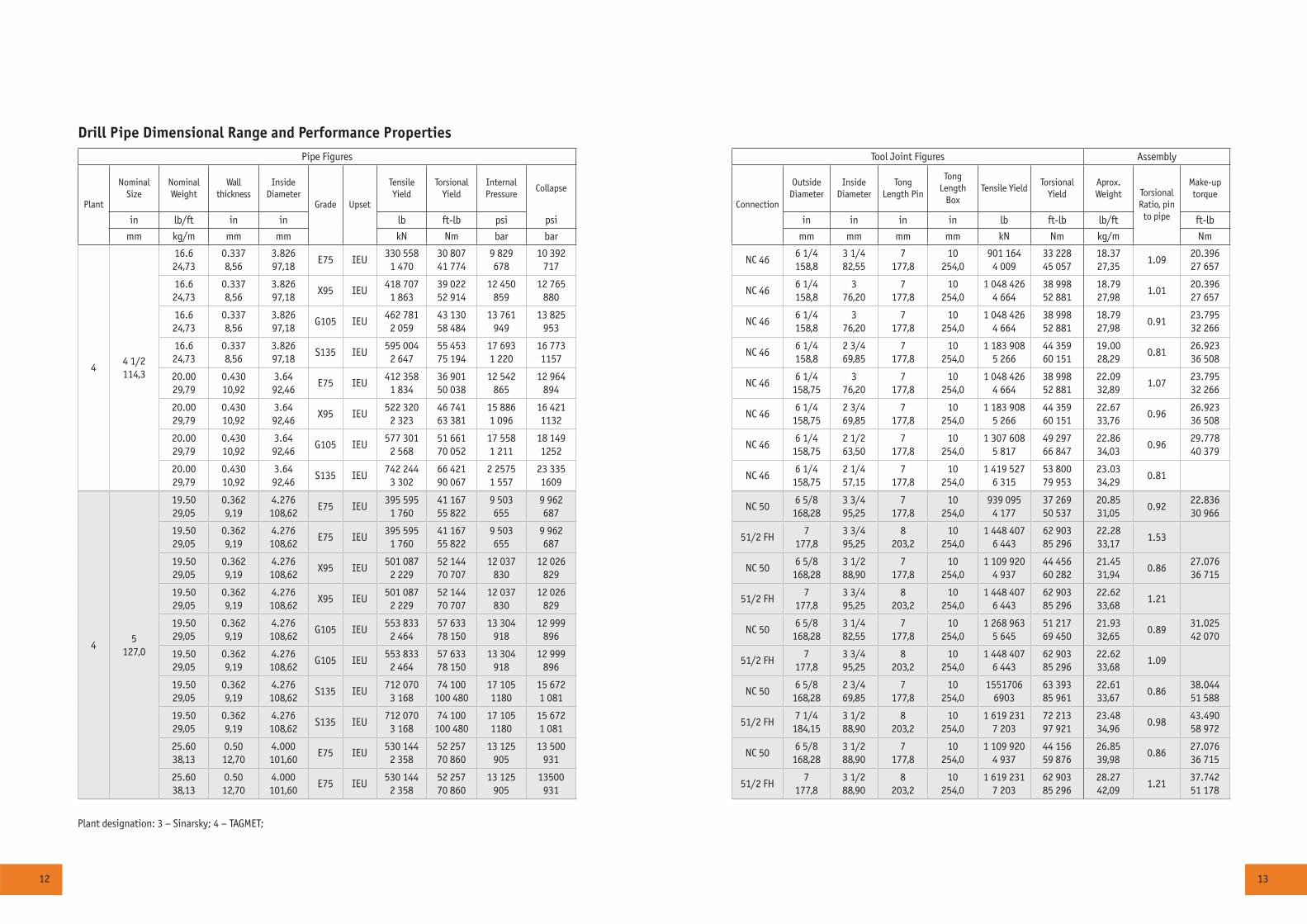
12 13
Drill Pipe Dimensional Range and Performance Properties
Pipe Figures Tool Joint Figures Assembly
Plant
Nominal Size
Nominal Weight
Wall thickness
Inside Diameter
Grade Upset
Tensile Yield
Torsional Yield
Internal Pressure
Collapse
Connection
Outside Diameter
Inside Diameter
Tong Length Pin
Tong Length
BoxTensile Yield
Torsional Yield
Aprox. Weight Torsional
Ratio, pin to pipe
Make-up torque
in lb/ft in in lb ft-lb psi psi in in in in lb ft-lb lb/ft ft-lb
mm kg/m mm mm kN Nm bar bar mm mm mm mm kN Nm kg/m Nm
44 1/2 114,3
16.6 24,73
0.337 8,56
3.826 97,18
E75 IEU330 558
1 47030 807 41 774
9 829 678
10 392 717
NC 466 1/4 158,8
3 1/4 82,55
7 177,8
10 254,0
901 164 4 009
33 228 45 057
18.37 27,35
1.0920.396 27 657
16.6 24,73
0.337 8,56
3.826 97,18
X95 IEU418 707
1 86339 022 52 914
12 450 859
12 765 880
NC 466 1/4 158,8
3 76,20
7 177,8
10 254,0
1 048 426 4 664
38 998 52 881
18.79 27,98
1.0120.396 27 657
16.6 24,73
0.337 8,56
3.826 97,18
G105 IEU462 781
2 05943 130 58 484
13 761 949
13 825 953
NC 466 1/4 158,8
3 76,20
7 177,8
10 254,0
1 048 426 4 664
38 998 52 881
18.79 27,98
0.9123.795 32 266
16.6 24,73
0.337 8,56
3.826 97,18
S135 IEU595 004
2 64755 453 75 194
17 693 1 220
16 773 1157
NC 466 1/4 158,8
2 3/4 69,85
7 177,8
10 254,0
1 183 908 5 266
44 359 60 151
19.00 28,29
0.8126.923 36 508
20.00 29,79
0.430 10,92
3.64 92,46
E75 IEU412 358
1 83436 901 50 038
12 542 865
12 964 894
NC 466 1/4
158,753
76,207
177,810
254,01 048 426
4 66438 998 52 881
22.09 32,89
1.0723.795 32 266
20.00 29,79
0.430 10,92
3.64 92,46
X95 IEU522 320
2 32346 741 63 381
15 886 1 096
16 421 1132
NC 466 1/4
158,752 3/4 69,85
7 177,8
10 254,0
1 183 908 5 266
44 359 60 151
22.67 33,76
0.9626.923 36 508
20.00 29,79
0.430 10,92
3.64 92,46
G105 IEU577 301
2 56851 661 70 052
17 558 1 211
18 149 1252
NC 466 1/4
158,752 1/2 63,50
7 177,8
10 254,0
1 307 608 5 817
49 297 66 847
22.86 34,03
0.9629.778 40 379
20.00 29,79
0.430 10,92
3.64 92,46
S135 IEU742 244
3 30266 421 90 067
2 2575 1 557
23 335 1609
NC 466 1/4
158,752 1/4 57,15
7 177,8
10 254,0
1 419 527 6 315
53 800 79 953
23.03 34,29
0.81
45
127,0
19.50 29,05
0.362 9,19
4.276 108,62
E75 IEU395 595
1 76041 167 55 822
9 503 655
9 962 687
NC 506 5/8
168,283 3/4 95,25
7 177,8
10 254,0
939 095 4 177
37 269 50 537
20.85 31,05
0.9222.836 30 966
19.50 29,05
0.362 9,19
4.276 108,62
E75 IEU395 595
1 76041 167 55 822
9 503 655
9 962 687
51/2 FH7
177,83 3/4 95,25
8 203,2
10 254,0
1 448 407 6 443
62 903 85 296
22.28 33,17
1.53
19.50 29,05
0.362 9,19
4.276 108,62
X95 IEU501 087
2 22952 144 70 707
12 037 830
12 026 829
NC 506 5/8
168,283 1/2 88,90
7 177,8
10 254,0
1 109 920 4 937
44 456 60 282
21.45 31,94
0.8627.076 36 715
19.50 29,05
0.362 9,19
4.276 108,62
X95 IEU501 087
2 22952 144 70 707
12 037 830
12 026 829
51/2 FH7
177,83 3/4 95,25
8 203,2
10 254,0
1 448 407 6 443
62 903 85 296
22.62 33,68
1.21
19.50 29,05
0.362 9,19
4.276 108,62
G105 IEU553 833
2 46457 633 78 150
13 304 918
12 999 896
NC 506 5/8
168,283 1/4 82,55
7 177,8
10 254,0
1 268 963 5 645
51 217 69 450
21.93 32,65
0.8931.025 42 070
19.50 29,05
0.362 9,19
4.276 108,62
G105 IEU553 833
2 46457 633 78 150
13 304 918
12 999 896
51/2 FH7
177,83 3/4 95,25
8 203,2
10 254,0
1 448 407 6 443
62 903 85 296
22.62 33,68
1.09
19.50 29,05
0.362 9,19
4.276 108,62
S135 IEU712 070
3 16874 100
100 48017 105 1180
15 672 1 081
NC 506 5/8
168,282 3/4 69,85
7 177,8
10 254,0
1551706 6903
63 393 85 961
22.61 33,67
0.8638.044 51 588
19.50 29,05
0.362 9,19
4.276 108,62
S135 IEU712 070
3 16874 100
100 48017 105 1180
15 672 1 081
51/2 FH7 1/4
184,153 1/2 88,90
8 203,2
10 254,0
1 619 231 7 203
72 213 97 921
23.48 34,96
0.9843.490 58 972
25.60 38,13
0.50 12,70
4.000 101,60
E75 IEU530 144
2 35852 257 70 860
13 125 905
13 500 931
NC 506 5/8
168,283 1/2 88,90
7 177,8
10 254,0
1 109 920 4 937
44 156 59 876
26.85 39,98
0.8627.076 36 715
25.60 38,13
0.50 12,70
4.000 101,60
E75 IEU530 144
2 35852 257 70 860
13 125 905
13500 931
51/2 FH7
177,83 1/2 88,90
8 203,2
10 254,0
1 619 231 7 203
62 903 85 296
28.27 42,09
1.2137.742 51 178
Plant designation: 3 – Sinarsky; 4 – TAGMET;
14 15
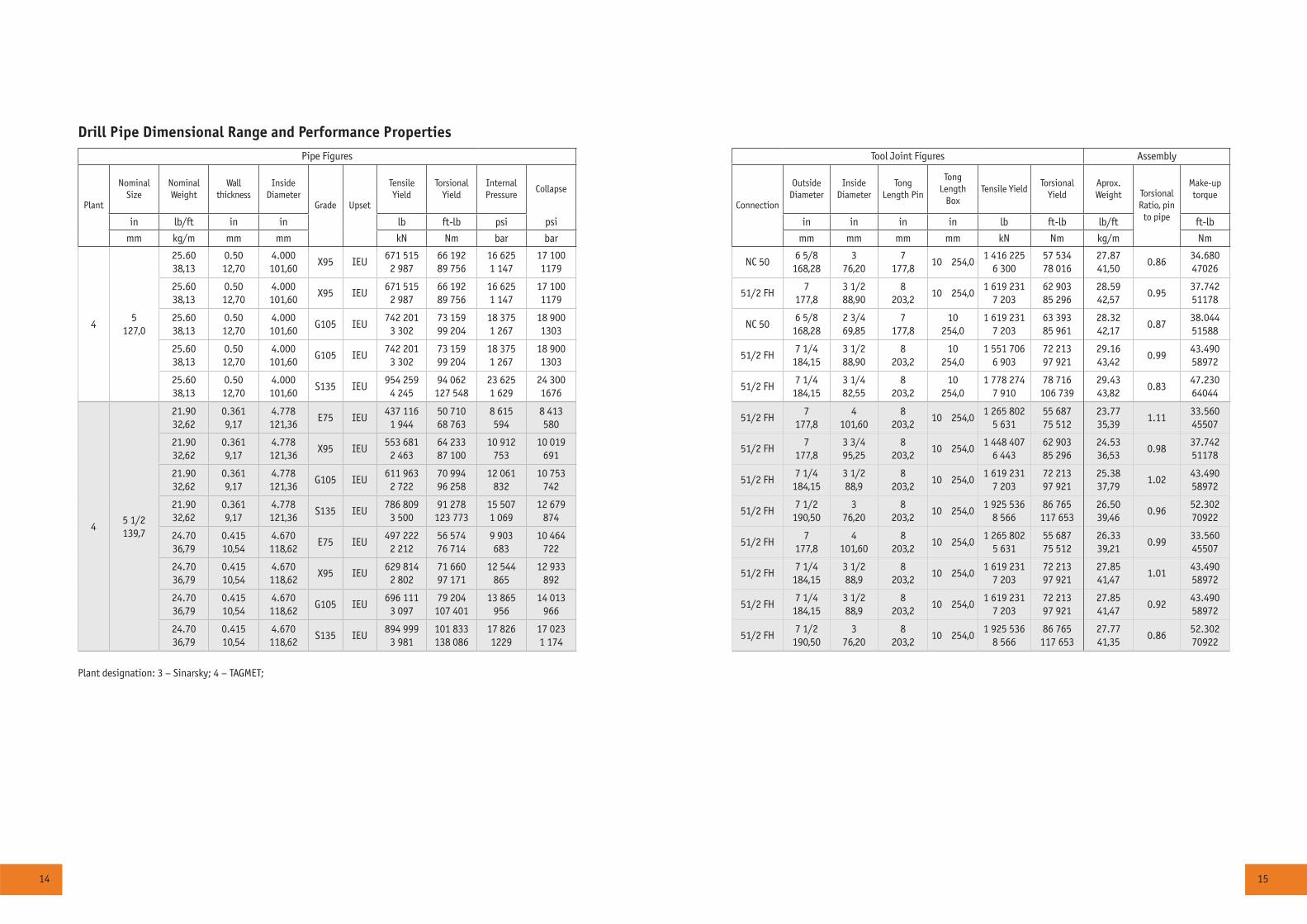
Drill Pipe Dimensional Range and Performance Properties
Pipe Figures Tool Joint Figures Assembly
Plant
Nominal Size
Nominal Weight
Wall thickness
Inside Diameter
Grade Upset
Tensile Yield
Torsional Yield
Internal Pressure
Collapse
Connection
Outside Diameter
Inside Diameter
Tong Length Pin
Tong Length
BoxTensile Yield
Torsional Yield
Aprox. Weight Torsional
Ratio, pin to pipe
Make-up torque
in lb/ft in in lb ft-lb psi psi in in in in lb ft-lb lb/ft ft-lb
mm kg/m mm mm kN Nm bar bar mm mm mm mm kN Nm kg/m Nm
45
127,0
25.60 38,13
0.50 12,70
4.000 101,60
X95 IEU671 515
2 98766 192 89 756
16 625 1 147
17 100 1179
NC 506 5/8
168,283
76,207
177,810 254,0
1 416 225 6 300
57 534 78 016
27.87 41,50
0.8634.680 47026
25.60 38,13
0.50 12,70
4.000 101,60
X95 IEU671 515
2 98766 192 89 756
16 6251 147
17 100 1179
51/2 FH7
177,83 1/2 88,90
8 203,2
10 254,01 619 231
7 20362 903 85 296
28.59 42,57
0.9537.742 51178
25.60 38,13
0.50 12,70
4.000 101,60
G105 IEU742 201
3 30273 159 99 204
18 375 1 267
18 900 1303
NC 506 5/8
168,282 3/4 69,85
7 177,8
10 254,0
1 619 231 7 203
63 393 85 961
28.32 42,17
0.8738.044 51588
25.60 38,13
0.50 12,70
4.000 101,60
G105 IEU742 201
3 30273 159 99 204
18 375 1 267
18 900 1303
51/2 FH7 1/4
184,153 1/2 88,90
8 203,2
10 254,0
1 551 706 6 903
72 213 97 921
29.16 43,42
0.9943.490 58972
25.60 38,13
0.50 12,70
4.000 101,60
S135 IEU954 259
4 24594 062
127 54823 625 1 629
24 300 1676
51/2 FH7 1/4
184,153 1/4 82,55
8 203,2
10 254,0
1 778 274 7 910
78 716 106 739
29.43 43,82
0.8347.230 64044
45 1/2 139,7
21.90 32,62
0.361 9,17
4.778 121,36
E75 IEU437 116
1 94450 710 68 763
8 615 594
8 413 580
51/2 FH7
177,84
101,608
203,210 254,0
1 265 802 5 631
55 687 75 512
23.77 35,39
1.1133.560 45507
21.90 32,62
0.361 9,17
4.778 121,36
X95 IEU553 681
2 46364 233 87 100
10 912 753
10 019 691
51/2 FH7
177,83 3/4 95,25
8 203,2
10 254,01 448 407
6 44362 903 85 296
24.53 36,53
0.9837.742 51178
21.90 32,62
0.361 9,17
4.778 121,36
G105 IEU611 963
2 72270 994 96 258
12 061 832
10 753 742
51/2 FH7 1/4
184,153 1/2 88,9
8 203,2
10 254,01 619 231
7 20372 213 97 921
25.38 37,79
1.0243.490 58972
21.90 32,62
0.361 9,17
4.778 121,36
S135 IEU786 809
3 50091 278
123 77315 507 1 069
12 679 874
51/2 FH7 1/2
190,503
76,208
203,210 254,0
1 925 536 8 566
86 765 117 653
26.50 39,46
0.9652.302 70922
24.70 36,79
0.415 10,54
4.670 118,62
E75 IEU497 222
2 21256 574 76 714
9 903 683
10 464 722
51/2 FH7
177,84
101,608
203,210 254,0
1 265 802 5 631
55 687 75 512
26.33 39,21
0.9933.560 45507
24.70 36,79
0.415 10,54
4.670 118,62
X95 IEU629 814
2 80271 660 97 171
12 544 865
12 933 892
51/2 FH7 1/4
184,153 1/2 88,9
8 203,2
10 254,01 619 231
7 20372 213 97 921
27.85 41,47
1.0143.490 58972
24.70 36,79
0.415 10,54
4.670 118,62
G105 IEU696 111
3 09779 204
107 40113 865
95614 013
96651/2 FH
7 1/4 184,15
3 1/2 88,9
8 203,2
10 254,01 619 231
7 20372 213 97 921
27.85 41,47
0.9243.490 58972
24.70 36,79
0.415 10,54
4.670 118,62
S135 IEU894 999
3 981101 833 138 086
17 826 1229
17 023 1 174
51/2 FH7 1/2
190,503
76,208
203,210 254,0
1 925 536 8 566
86 765 117 653
27.77 41,35
0.8652.302 70922
Plant designation: 3 – Sinarsky; 4 – TAGMET;
16 17
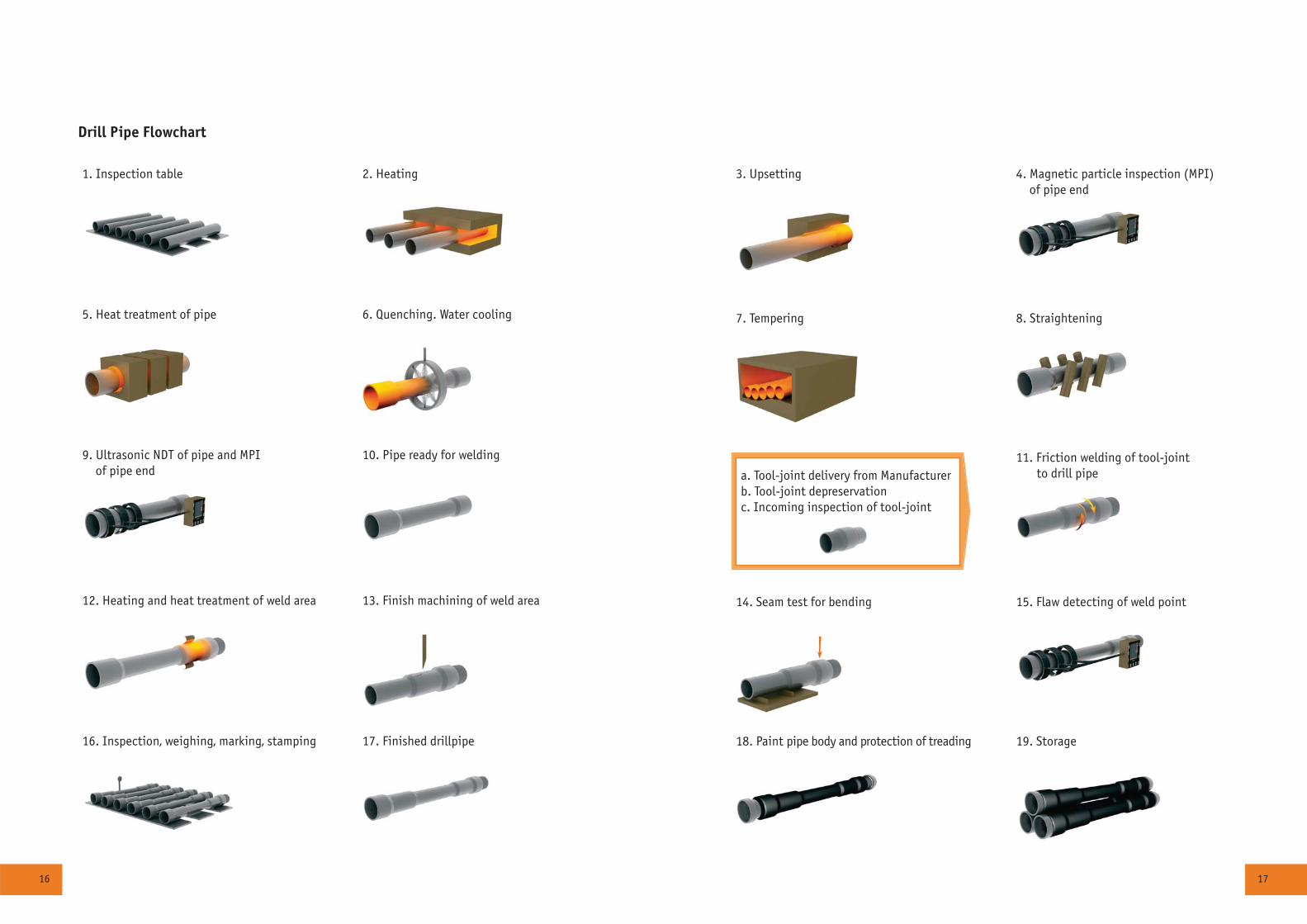
3. Upsetting 4. Magnetic particle inspection (MPI) of pipe end
7. Tempering 8. Straightening
a. Tool-joint delivery from Manufacturerb. Tool-joint depreservationc. Incoming inspection of tool-joint
11. Friction welding of tool-joint to drill pipe
14. Seam test for bending 15. Flaw detecting of weld point
18. Paint pipe body and protection of treading 19. Storage
1. Inspection table 2. Heating
5. Heat treatment of pipe 6. Quenching. Water cooling
9. Ultrasonic NDT of pipe and MPI of pipe end
10. Pipe ready for welding
12. Heating and heat treatment of weld area 13. Finish machining of weld area
16. Inspection, weighing, marking, stamping 17. Finished drillpipe
Drill Pipe Flowchart
18 19
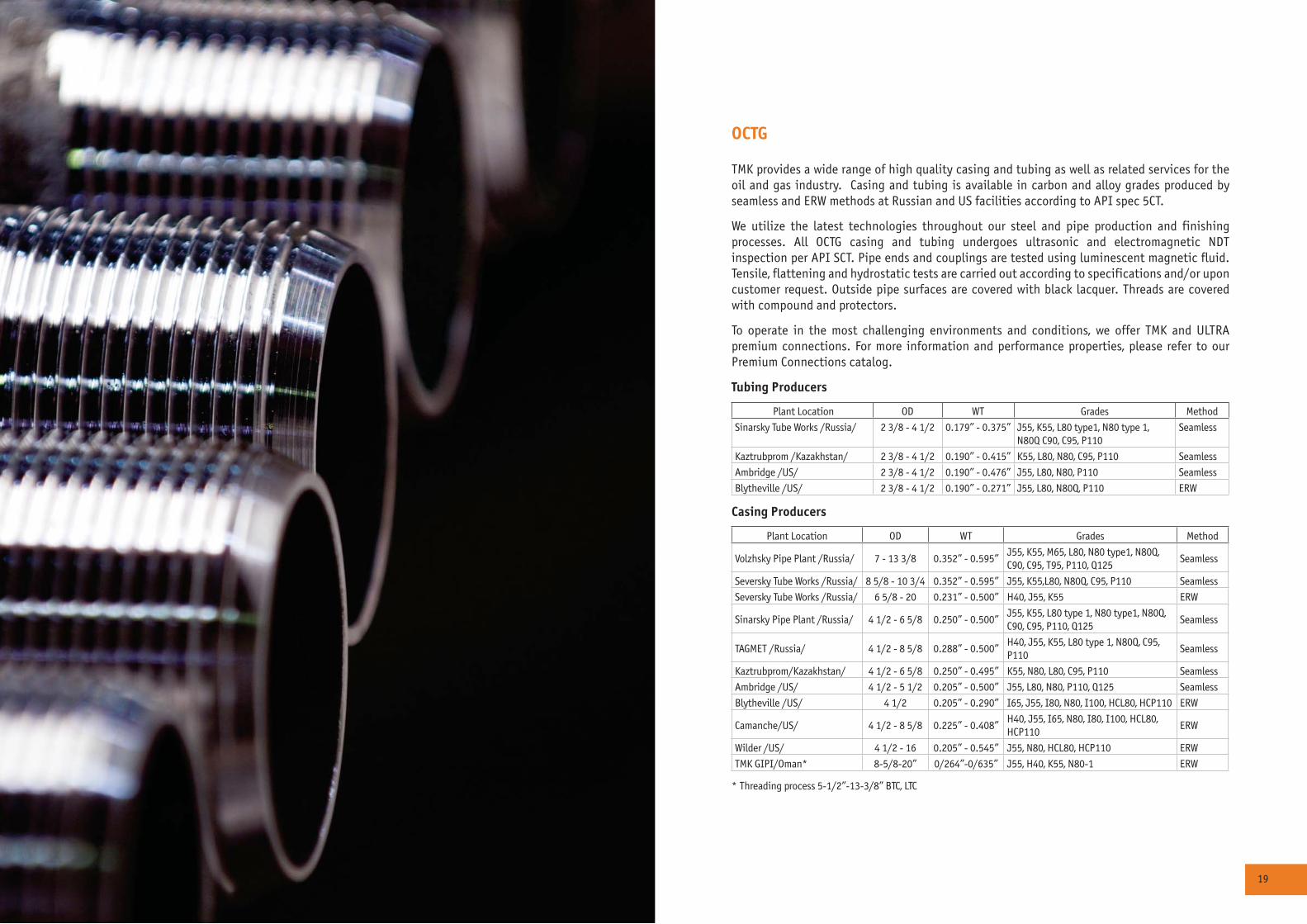
OCTG
TMK provides a wide range of high quality casing and tubing as well as related services for the oil and gas industry. Casing and tubing is available in carbon and alloy grades produced by seamless and ERW methods at Russian and US facilities according to API spec 5CT.
We utilize the latest technologies throughout our steel and pipe production and finishing processes. All OCTG casing and tubing undergoes ultrasonic and electromagnetic NDT inspection per API SCT. Pipe ends and couplings are tested using luminescent magnetic fluid. Tensile, flattening and hydrostatic tests are carried out according to specifications and/or upon customer request. Outside pipe surfaces are covered with black lacquer. Threads are covered with compound and protectors.
To operate in the most challenging environments and conditions, we offer TMK and ULTRA premium connections. For more information and performance properties, please refer to our Premium Connections catalog.
Tubing Producers
Plant Location OD WT Grades Method
Sinarsky Tube Works /Russia/ 2 3/8 - 4 1/2 0.179” - 0.375” J55, K55, L80 type1, N80 type 1, N80Q C90, C95, P110
Seamless
Kaztrubprom /Kazakhstan/ 2 3/8 - 4 1/2 0.190” - 0.415” K55, L80, N80, C95, P110 Seamless
Ambridge /US/ 2 3/8 - 4 1/2 0.190” - 0.476” J55, L80, N80, P110 Seamless
Blytheville /US/ 2 3/8 - 4 1/2 0.190” - 0.271” J55, L80, N80Q, P110 ERW
Casing Producers
Plant Location OD WT Grades Method
Volzhsky Pipe Plant /Russia/ 7 - 13 3/8 0.352” - 0.595”J55, K55, M65, L80, N80 type1, N80Q, C90, C95, T95, P110, Q125
Seamless
Seversky Tube Works /Russia/ 8 5/8 - 10 3/4 0.352” - 0.595” J55, K55,L80, N80Q, C95, P110 Seamless
Seversky Tube Works /Russia/ 6 5/8 - 20 0.231” - 0.500” H40, J55, K55 ERW
Sinarsky Pipe Plant /Russia/ 4 1/2 - 6 5/8 0.250” - 0.500”J55, K55, L80 type 1, N80 type1, N80Q, C90, C95, P110, Q125
Seamless
TAGMET /Russia/ 4 1/2 - 8 5/8 0.288” - 0.500”H40, J55, K55, L80 type 1, N80Q, C95, P110
Seamless
Kaztrubprom/Kazakhstan/ 4 1/2 - 6 5/8 0.250” - 0.495” K55, N80, L80, C95, P110 Seamless
Ambridge /US/ 4 1/2 - 5 1/2 0.205” - 0.500” J55, L80, N80, P110, Q125 Seamless
Blytheville /US/ 4 1/2 0.205” - 0.290” I65, J55, I80, N80, I100, HCL80, HCP110 ERW
Camanche/US/ 4 1/2 - 8 5/8 0.225” - 0.408” H40, J55, I65, N80, I80, I100, HCL80, HCP110
ERW
Wilder /US/ 4 1/2 - 16 0.205” - 0.545” J55, N80, HCL80, HCP110 ERW
TMK GIPI/Oman* 8-5/8-20” 0/264”-0/635” J55, H40, K55, N80-1 ERW
* Threading process 5-1/2”-13-3/8” BTC, LTC
20 21
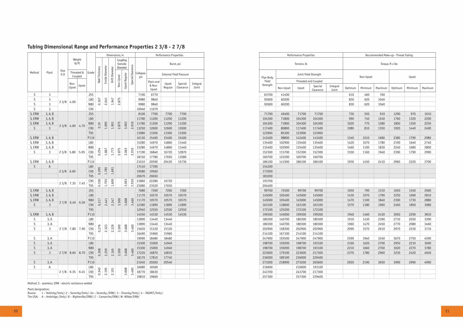
Tubing Dimensional Range and Performance Properties 2 3/8 - 2 7/8
Method PlantSize O.D
Weight lb/ft
Grade
Dimensions, in Performance Properties Performance Properties Recommended Make-up - Thread Tubing
Wal
l Thi
ckne
ss
Insi
de D
iam
eter
Drift
Dia
met
er
Coupling Outside Diameter
Spec
ial C
lear
ance
Collapse, psi
Burst, psi Tension, lb Torque, ft x lbs
Threaded & Coupled
Non
-Ups
et
Ups
et R
egul
ar Internal Yield PressurePipe Body
YieldStrength
Joint Yield StrengthNon-Upset Upset
Non-Upset
UpsetPlain-end
& Non-Upset
UpsetRegular
Special Clearance
Integral Joint
Threaded and Coupled
Non-Upset UpsetSpecial
ClearanceIntegral
JointOptimum Minimum Maximum Optimum Minimum Maximum
S 3
2 3/8 4.00
J550.
167
2.04
1
1.94
7
2.87
5
7190 6770 63700 41400 610 460 760S 3 L80 9980 9840 92600 60200 830 620 1040S 3 N80 9980 9840 92600 60200 830 620 1040S 3 C90 10940 11070
S, ERW 3, A, B
2 3/8 4.60 4.70
J55
0.19
1.99
5
1.90
1
2.87
5
3.06
3
2.91
0
8100 7700 7700 7700 71700 49400 71700 71700 730 550 910 1290 970 1610S, ERW 3, A, B L80 11780 11200 11200 11200 104300 71800 104300 104300 990 740 1240 1760 1320 2200S, ERW 3, A, B N80 11780 11200 11200 11200 104300 71800 104300 104300 1020 770 1280 1800 1350 2250
S 3 C90 13250 12600 12600 12600 117400 80800 117400 117400 1080 810 1350 1920 1440 2400T95 13980 13300 13300 13300 123900 85300 123900 123900
S, ERW 3, A, B P110 16130 15400 15400 15400 143400 98800 143400 143400 1340 1010 1680 2380 1790 2980S, ERW 3, A, B
2 3/8 5.80 5.95
L80
0.25
4
1.86
7
1.77
3
2.87
5
3.06
3
2.91
0
15280 14970 14860 11440 135400 102900 135400 135400 1420 1070 1780 2190 1640 2740S, ERW 3, A, B N80 15280 14970 14860 11440 135400 102900 135400 135400 1460 1100 1830 2240 1680 2800
S 3 C90 17190 16840 16720 12870 152300 115700 152300 152300 1550 1160 1940 2390 1790 2990T95 18150 17780 17650 13580 160700 122200 160700 160700
S, ERW 3, A, B P110 21010 20590 20430 15730 186100 141500 186100 186100 1930 1450 2410 2960 2220 3700S A
2 3/8 6.60L80
0.29
5
1.78
5
1.69
1 17410 17390 154200C90 19580 19560 173500T95 20670 20650 183200
2 3/8 7.35 7.45C90
0.33
6
1.70
3
1.60
9
3.06
3
2.91
0 21860 22280 16720 193700T95 23080 23520 17650 204400
S, ERW 3, A, B
2 7/8 6.40 6.50
J55
0.21
7
2.44
1
2.34
7
3.50
0
3.66
8
3.46
0
7680 7260 7260 7260 99700 72500 99700 99700 1050 790 1310 1650 1240 2060S, ERW 3, A, B L80 11170 10570 10570 10570 145000 105400 145000 145000 1430 1070 1790 2250 1690 2810S, ERW 3, A, B N80 11170 10570 10570 10570 145000 105400 145000 145000 1470 1100 1840 2300 1730 2880
S 3 C90 12380 11890 11890 11890 163100 118600 163100 163100 1570 1180 1960 2460 1850 3080T95 12940 12550 12550 12550 172100 125200 172100 172100
S, ERW 3, A, B P110 14550 14530 14530 14530 199300 145000 199300 199300 1940 1460 2430 3050 2290 3810S 3, A
2 7/8 7.80 7.90
L80
0.27
6
2.32
3
2.22
9
3.50
0
3.66
8
3.46
0
13890 13440 13440 180300 140700 180300 180300 1910 1430 2390 2710 2030 3390S 3, A N80 13890 13440 13440 180300 140700 180300 180300 1960 1470 2450 2770 2080 3460S 3 C90 15620 15120 15120 202900 158300 202900 202900 2090 1570 2610 2970 2230 3710
T95 16490 15960 15960 214100 167100 214100 214100S 3, A P110 19090 18480 18480 247900 193500 247900 247900 2590 1940 3240 3670 2750 4590S 3, A
2 7/8 8.60 8.70
L80
0.30
8
2.25
9
2.16
5
3.50
0
3.66
8
3.46
0
15300 15000 14940 198700 159200 198700 193100 2160 1620 2700 2950 2210 3690S 3, A N80 15300 15000 14940 198700 159200 198700 193100 2210 1660 2760 3020 2270 3780S 3 C90 17220 16870 16810 223600 179100 223600 217300 2370 1780 2960 3230 2420 4040
T95 18170 17810 17740 236000 189100 236000 229400S 3, A P110 21040 20260 20540 273200 218900 273200 265600 2920 2190 3650 3990 2990 4990S A
2 7/8 9.35 9.45L80
0.34
0
2.19
5
2.10
1
3.66
8
3.46
0 16680 16560 216600 216600 193100C90 18770 18630 243700 243700 217300T95 19810 19660 257300 257300 229400
Method: S - seamless; ERW - electric resistance welded
Plant designation:Russia: 1 – Volzhsky/Smls/; 2 – Seversky/Smls/; 2w – Seversky /ERW/; 3 – Sinarsky/Smls/; 4 – TAGMET/Smls/;The USA: A – Ambridge /Smls/; B – Blytheville/ERW/; C – Camanche/ERW/; W- Wilder/ERW/
22 23
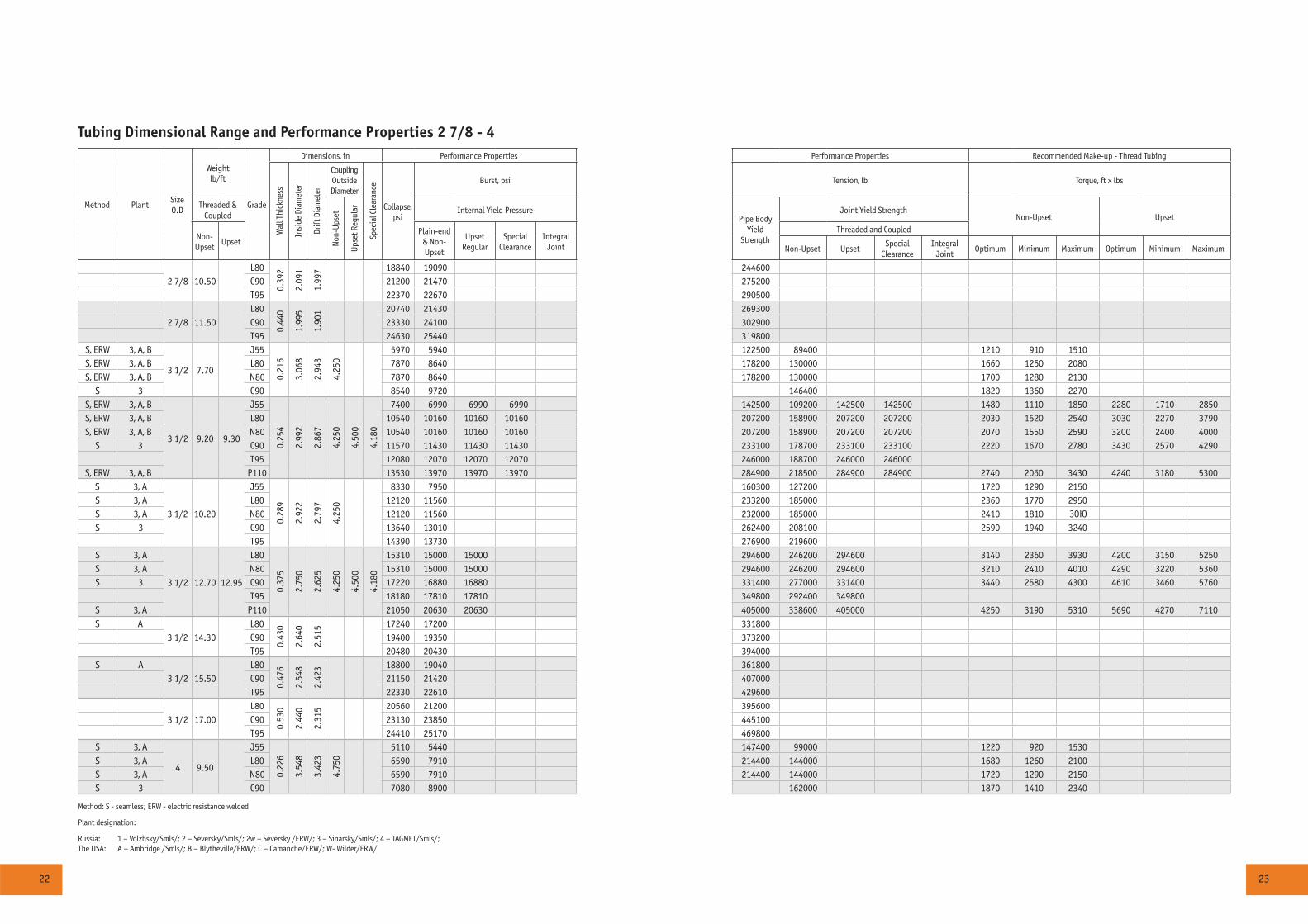
Tubing Dimensional Range and Performance Properties 2 7/8 - 4
Method PlantSize O.D
Weight lb/ft
Grade
Dimensions, in Performance Properties Performance Properties Recommended Make-up - Thread Tubing
Wal
l Thi
ckne
ss
Insi
de D
iam
eter
Drift
Dia
met
er
Coupling Outside Diameter
Spec
ial C
lear
ance
Collapse, psi
Burst, psi Tension, lb Torque, ft x lbs
Threaded & Coupled
Non
-Ups
et
Ups
et R
egul
ar Internal Yield PressurePipe Body
YieldStrength
Joint Yield StrengthNon-Upset Upset
Non-Upset
UpsetPlain-end
& Non-Upset
UpsetRegular
Special Clearance
Integral Joint
Threaded and Coupled
Non-Upset UpsetSpecial
ClearanceIntegral
JointOptimum Minimum Maximum Optimum Minimum Maximum
2 7/8 10.50L80
0.39
2
2.09
1
1.99
7 18840 19090 244600C90 21200 21470 275200T95 22370 22670 290500
2 7/8 11.50L80
0.44
0
1.99
5
1.90
1 20740 21430 269300C90 23330 24100 302900T95 24630 25440 319800
S, ERW 3, A, B
3 1/2 7.70
J55
0.21
6
3.06
8
2.94
3
4.25
0
5970 5940 122500 89400 1210 910 1510S, ERW 3, A, B L80 7870 8640 178200 130000 1660 1250 2080S, ERW 3, A, B N80 7870 8640 178200 130000 1700 1280 2130
S 3 C90 8540 9720 146400 1820 1360 2270S, ERW 3, A, B
3 1/2 9.20 9.30
J55
0.25
4
2.99
2
2.86
7
4.25
0
4.50
0
4.18
0
7400 6990 6990 6990 142500 109200 142500 142500 1480 1110 1850 2280 1710 2850S, ERW 3, A, B L80 10540 10160 10160 10160 207200 158900 207200 207200 2030 1520 2540 3030 2270 3790S, ERW 3, A, B N80 10540 10160 10160 10160 207200 158900 207200 207200 2070 1550 2590 3200 2400 4000
S 3 C90 11570 11430 11430 11430 233100 178700 233100 233100 2220 1670 2780 3430 2570 4290T95 12080 12070 12070 12070 246000 188700 246000 246000
S, ERW 3, A, B P110 13530 13970 13970 13970 284900 218500 284900 284900 2740 2060 3430 4240 3180 5300S 3, A
3 1/2 10.20
J55
0.28
9
2.92
2
2.79
7
4.25
0
8330 7950 160300 127200 1720 1290 2150S 3, A L80 12120 11560 233200 185000 2360 1770 2950S 3, A N80 12120 11560 232000 185000 2410 1810 ÇÎÞS 3 C90 13640 13010 262400 208100 2590 1940 3240
T95 14390 13730 276900 219600S 3, A
3 1/2 12.70 12.95
L80
0.37
5
2.75
0
2.62
5
4.25
0
4.50
0
4.18
0
15310 15000 15000 294600 246200 294600 3140 2360 3930 4200 3150 5250S 3, A N80 15310 15000 15000 294600 246200 294600 3210 2410 4010 4290 3220 5360S 3 C90 17220 16880 16880 331400 277000 331400 3440 2580 4300 4610 3460 5760
T95 18180 17810 17810 349800 292400 349800S 3, A P110 21050 20630 20630 405000 338600 405000 4250 3190 5310 5690 4270 7110S A
3 1/2 14.30L80
0.43
0
2.64
0
2.51
5 17240 17200 331800C90 19400 19350 373200T95 20480 20430 394000
S A3 1/2 15.50
L80
0.47
6
2.54
8
2.42
3 18800 19040 361800C90 21150 21420 407000T95 22330 22610 429600
3 1/2 17.00L80
0.53
0
2.44
0
2.31
5 20560 21200 395600C90 23130 23850 445100T95 24410 25170 469800
S 3, A
4 9.50
J55
0.22
6
3.54
8
3.42
3
4.75
0
5110 5440 147400 99000 1220 920 1530S 3, A L80 6590 7910 214400 144000 1680 1260 2100S 3, A N80 6590 7910 214400 144000 1720 1290 2150S 3 C90 7080 8900 162000 1870 1410 2340
Method: S - seamless; ERW - electric resistance welded
Plant designation:
Russia: 1 – Volzhsky/Smls/; 2 – Seversky/Smls/; 2w – Seversky /ERW/; 3 – Sinarsky/Smls/; 4 – TAGMET/Smls/;The USA: A – Ambridge /Smls/; B – Blytheville/ERW/; C – Camanche/ERW/; W- Wilder/ERW/
24 25
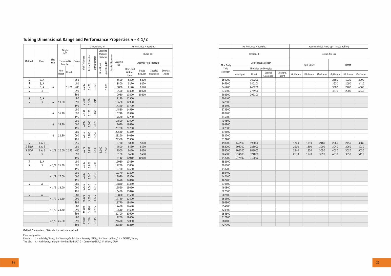
Tubing Dimensional Range and Performance Properties 4 - 4 1/2
Method PlantSize O.D
Weight lb/ft
Grade
Dimensions, in Performance Properties Performance Properties Recommended Make-up - Thread Tubing
Wal
l Thi
ckne
ss
Insi
de D
iam
eter
Drift
Dia
met
er
Coupling Outside Diameter
Spec
ial C
lear
ance
Collapse, psi
Burst, psi Tension, lb Torque, ft x lbs
Threaded & Coupled
Non
-Ups
et
Ups
et R
egul
ar Internal Yield PressurePipe Body
YieldStrength
Joint Yield StrengthNon-Upset Upset
Non-Upset
UpsetPlain-end
& Non-Upset
UpsetRegular
Special Clearance
Integral Joint
Threaded and Coupled
Non-Upset UpsetSpecial
ClearanceIntegral
JointOptimum Minimum Maximum Optimum Minimum Maximum
S 3, A
4 11.00
J550.
262
3.47
6
3.35
1
5.00
0
6590 6300 6300 169200 169200 2560 1920 3200S 3, A L80 8800 9170 9170 246200 246200 3530 2650 4410S 3, A N80 8800 9170 9170 246200 246200 3600 2700 4500S 3 C90 9590 10320 10320 276900 276900 3870 2900 4840
T95 9980 10890 10890 292300 292300S 3, A
4 13.20L80
0.33
0
3.34
0
3.21
5 12110 11550 304400S 3 C90 13620 12990 342500
T95 14380 13720 361500
4 16.10L80
0.41
5
3.17
0
3.04
5 14880 14530 373900C90 16740 16340 420700T95 17670 17250 444000
4 18.90L80
0.50
0
3.00
0
2.87
5 17500 17500 439800C90 19690 19690 494800T95 20780 20780 522300
4 22.20L80
0.61
0
2.78
0
2.65
5 20680 21350 519800C90 23260 24020 584700T95 24560 25350 617200
S 3, A, B
4 1/2 12.60 12.75
J55
0.27
1
3.95
8
3.83
3
5.20
0
5.56
3
5730 5800 5800 198000 143500 198000 1740 1310 2180 2860 2150 3580S, ERW 3, A, B L80 7500 8430 8430 288000 208700 288000 2400 1800 3000 3940 2960 4930S, ERW 3, A, B N80 7500 8430 8430 288000 208700 288000 2440 1830 3050 4020 3020 5030
S 3 C90 8120 9490 9490 324000 234800 324000 2630 1970 3290 4330 3250 5410T95 8410 10010 10010 342000 247900 342000
S 3, A4 1/2 15.20
L80
0.33
7
3.82
6
3.70
1 11080 10480 352600S 3 C90 12220 11800 396600
T95 12760 12450 418700
4 1/2 17.00L80
0.38
0
3.74
0
3.61
5 12370 11820 393400C90 13920 13300 442600T95 14690 14040 467200
S A4 1/2 18.90
L80
0.43
0
3.64
0
3.51
5 13830 13380 439800C90 15560 15050 494800T95 16420 15890 522300
S A4 1/2 21.50
L80
0.50
0
3.50
0
3.37
5 15800 15560 502600C90 17780 17500 565500T95 18770 18470 596900
4 1/2 23.70L80
0.56
0
3.38
0
3.25
5 17430 17420 554600C90 19610 19600 623900T95 20700 20690 658500
4 1/2 26.00L80
0.63
0
3.24
0
3.11
5 19260 19600 612800C90 21670 22050 689400T95 22880 23280 727700
Method: S - seamless; ERW - electric resistance welded
Plant designation:Russia: 1 – Volzhsky/Smls/; 2 – Seversky/Smls/; 2w – Seversky /ERW/; 3 – Sinarsky/Smls/; 4 – TAGMET/Smls/;The USA: A – Ambridge /Smls/; B – Blytheville/ERW/; C – Camanche/ERW/; W- Wilder/ERW/
26 27
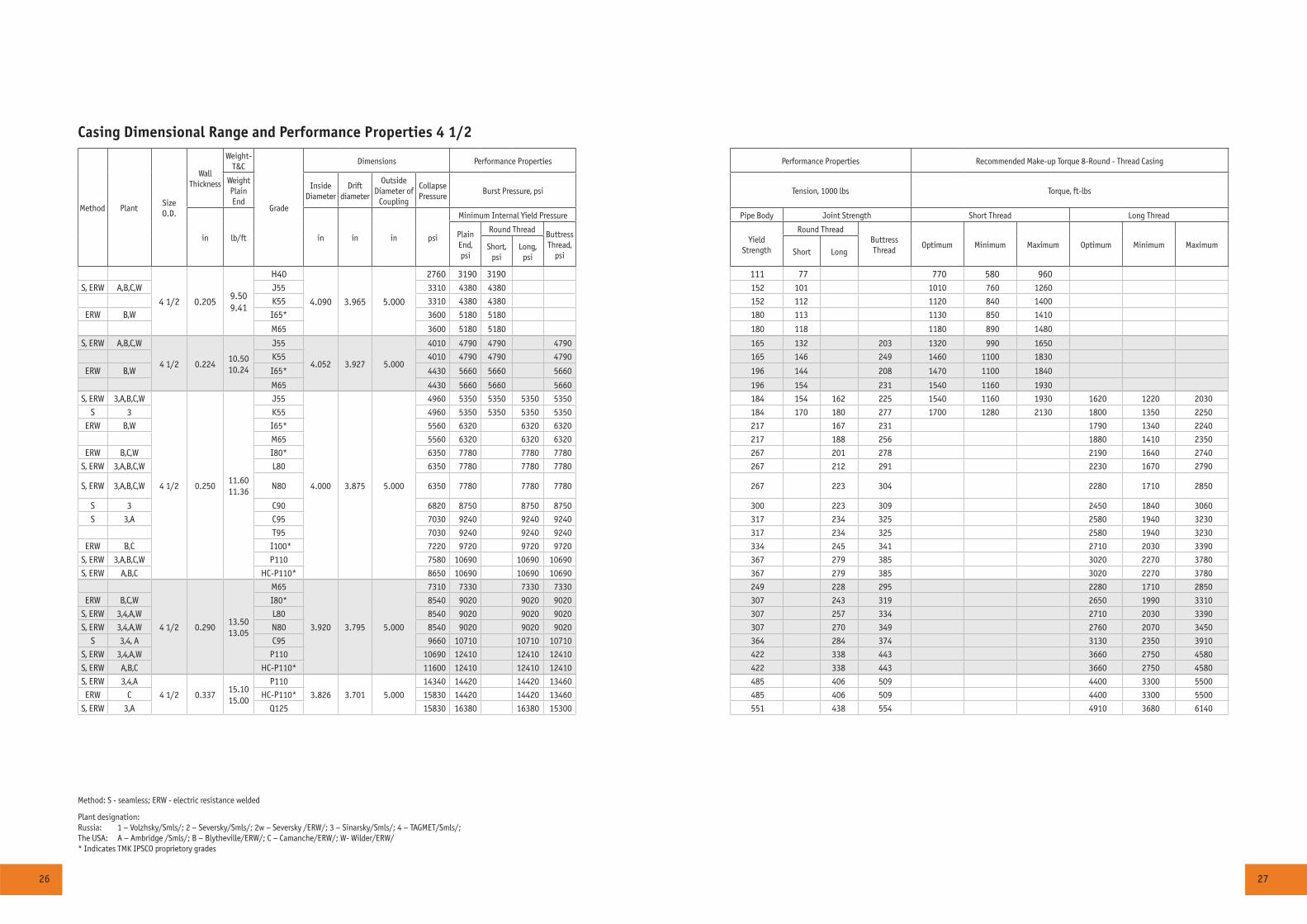
Casing Dimensional Range and Performance Properties 4 1/2
Method PlantSize O.D.
WallThickness
Weight-T&C
Grade
Dimensions Performance Properties Performance Properties Recommended Make-up Torque 8-Round - Thread Casing
Weight Plain End
Inside Diameter
Drift diameter
OutsideDiameter of
Coupling
Collapse Pressure
Burst Pressure, psi Tension, 1000 lbs Torque, ft-lbs
in lb/ft in in in psi
Minimum Internal Yield Pressure Pipe Body Joint Strength Short Thread Long Thread
PlainEnd,psi
Round Thread Buttress Thread,
psi
Yield Strength
Round ThreadButtress Thread
Optimum Minimum Maximum Optimum Minimum MaximumShort,psi
Long,psi
Short Long
4 1/2 0.2059.509.41
H40
4.090 3.965 5.000
2760 3190 3190 111 77 770 580 960S, ERW A,B,C,W J55 3310 4380 4380 152 101 1010 760 1260
K55 3310 4380 4380 152 112 1120 840 1400
ERW B,W I65* 3600 5180 5180 180 113 1130 850 1410
M65 3600 5180 5180 180 118 1180 890 1480
S, ERW A,B,C,W
4 1/2 0.22410.5010.24
J55
4.052 3.927 5.000
4010 4790 4790 4790 165 132 203 1320 990 1650
K55 4010 4790 4790 4790 165 146 249 1460 1100 1830
ERW B,W I65* 4430 5660 5660 5660 196 144 208 1470 1100 1840
M65 4430 5660 5660 5660 196 154 231 1540 1160 1930
S, ERW 3,A,B,C,W
4 1/2 0.25011.6011.36
J55
4.000 3.875 5.000
4960 5350 5350 5350 5350 184 154 162 225 1540 1160 1930 1620 1220 2030
S 3 K55 4960 5350 5350 5350 5350 184 170 180 277 1700 1280 2130 1800 1350 2250
ERW B,W I65* 5560 6320 6320 6320 217 167 231 1790 1340 2240
M65 5560 6320 6320 6320 217 188 256 1880 1410 2350
ERW B,C,W I80* 6350 7780 7780 7780 267 201 278 2190 1640 2740
S, ERW 3,A,B,C,W L80 6350 7780 7780 7780 267 212 291 2230 1670 2790
S, ERW 3,A,B,C,W N80 6350 7780 7780 7780 267 223 304 2280 1710 2850
S 3 C90 6820 8750 8750 8750 300 223 309 2450 1840 3060
S 3,A C95 7030 9240 9240 9240 317 234 325 2580 1940 3230
T95 7030 9240 9240 9240 317 234 325 2580 1940 3230
ERW B,C I100* 7220 9720 9720 9720 334 245 341 2710 2030 3390
S, ERW 3,A,B,C,W P110 7580 10690 10690 10690 367 279 385 3020 2270 3780
S, ERW A,B,C HC-P110* 8650 10690 10690 10690 367 279 385 3020 2270 3780
4 1/2 0.29013.5013.05
M65
3.920 3.795 5.000
7310 7330 7330 7330 249 228 295 2280 1710 2850
ERW B,C,W I80* 8540 9020 9020 9020 307 243 319 2650 1990 3310
S, ERW 3,4,A,W L80 8540 9020 9020 9020 307 257 334 2710 2030 3390
S, ERW 3,4,A,W N80 8540 9020 9020 9020 307 270 349 2760 2070 3450
S 3,4, A C95 9660 10710 10710 10710 364 284 374 3130 2350 3910
S, ERW 3,4,A,W P110 10690 12410 12410 12410 422 338 443 3660 2750 4580
S, ERW A,B,C HC-P110* 11600 12410 12410 12410 422 338 443 3660 2750 4580
S, ERW 3,4,A
4 1/2 0.33715.1015.00
P110
3.826 3.701 5.000
14340 14420 14420 13460 485 406 509 4400 3300 5500
ERW C HC-P110* 15830 14420 14420 13460 485 406 509 4400 3300 5500
S, ERW 3,A Q125 15830 16380 16380 15300 551 438 554 4910 3680 6140
Method: S - seamless; ERW - electric resistance welded
Plant designation:Russia: 1 – Volzhsky/Smls/; 2 – Seversky/Smls/; 2w – Seversky /ERW/; 3 – Sinarsky/Smls/; 4 – TAGMET/Smls/;The USA: A – Ambridge /Smls/; B – Blytheville/ERW/; C – Camanche/ERW/; W- Wilder/ERW/ * Indicates TMK IPSCO proprietory grades

28 29
Casing Dimensional Range and Performance Properties 5
Method PlantSize O.D.
WallThickness
WeightT&C
Grade
Dimensions Performance Properties Performance Properties Recommended Make-up Torque 8-Round - Thread Casing
Weight Plain End
Inside iameter
Drift diameter
OutsideDiameter of
Coupling
Collapse Pressure
Burst Pressure. psi Tension. 1000 lbs Torque. ft-lbs
in lb/ft in in in psi
Minimum Internal Yield Pressure Pipe Body Joint Strength Short Thread Long Thread
PlainEnd.psi
Round Thread Buttress Thread.
psi
Yield Strength
Round ThreadButtress Thread
Optimum Minimum Maximum Optimum Minimum MaximumShort.psi
Long.psi
Short Long
S.ERW A.W5 0.220
11.5011.24
J554.560 4.435 5.563
3060 4240 4240 182 133 1330 1000 1660K55 3060 4240 4240 182 147 1470 1100 1840M65 3290 5010 5010 215 155 1550 1160 1940
S,ERW 3,A,W5 0.253
13.0012.84
J554.494 4.369 5.563
4140 4870 4870 4870 4870 208 169 182 252 1690 1270 2110 1820 1370 2280S 3 K55 4140 4870 4870 4870 4870 208 186 201 309 1860 1400 2330 2010 1510 2510
M65 4590 5760 5760 5760 5760 245 196 212 288 1960 1470 2450 2120 1590 2650S,ERW 3,4,A,W
5 0.29615.0014.88
J55
4.408 4.283 5.563
5560 5700 5700 5700 5700 241 207 223 293 2070 1550 2590 2230 1670 2790S 3,4 K55 5560 5700 5700 5700 5700 241 228 246 359 2280 1710 2850 2460 1850 3080
M65 6280 6730 6730 6730 284 259 334 2590 1940 3240S,ERW 3,4,A,W L80 7250 8290 8290 8290 350 295 379 3080 2310 3850S,ERW 3,4,A,W N80 7250 8290 8290 8290 350 311 396 3140 2360 3930
S 3 C90 7830 9320 9320 9320 394 311 404 3380 2540 4230S 3,4,A C95 8110 9840 9840 9840 416 326 424 3560 2670 4450
T95 8110 9840 9840 9840 416 326 424 3560 2670 4450S,ERW 3,4,A,W P110 8850 11400 11400 11400 481 388 503 4170 3130 5210
5 0.36218.0017.95
M65
4.276 4.151 5.563
8730 8240 8240 8240 343 331 402 3310 2480 4140S 3,4,A L80 10500 10140 10140 9910 422 376 457 3930 2950 4910S 3,4,A N80 10500 10140 10140 9910 422 396 477 4000 3000 5000S 3 C90 11520 11400 11400 11150 475 396 487 4310 3230 5390S 3,4,A C95 12030 12040 12040 11770 501 416 512 4550 3410 5690
T95 12030 12040 12040 11770 501 416 512 4550 3410 5690S 3,4,A P110 13470 13940 13940 13620 580 495 606 5310 3980 6640S 3,A Q125 14820 15840 15840 15840 659 535 661 5930 4450 7410
5 0.43721.4021.32
M65
4.126 4.001 5.563
10370 9940 9940 9910 407 409 478 4090 3070 5110S 4,A L80 12760 12240 10810 9910 501 466 510 4860 3650 6080S 4,A N80 12760 12240 10810 9910 501 490 536 4950 3710 6190
C90 14360 13770 12170 11150 564 490 536 5340 4010 6680S 4,A C95 15150 14530 12840 11770 595 515 563 5620 4220 7030
T95 15160 14530 12840 11770 595 515 563 5620 4220 7030S 4,A P110 17550 16820 14870 13620 689 613 671 6580 4940 8230S A Q125 19940 19120 16900 15480 783 662 724 7340 5510 9180S 4,A
5 0.47823.2023.11
L80
4.044 3.919 5.563
13830 13380 10810 9910 543 513 510 5350 4010 6690S 4.A N80 13830 13380 10810 9910 543 540 536 5450 4090 6810
C90 15560 15060 12170 11150 611 540 536 5880 4410 7350S 4,A C95 16430 15890 12840 11770 645 567 563 6200 4650 7750
T95 16430 15890 12840 11770 645 567 563 6200 4650 7750S 4.A P110 19020 18400 14870 13620 747 675 671 7250 5440 9060S A Q125 21620 20910 16900 15480 849 729 724 8090 6070 10110S 4.A
5 0.50024.1024.05
L80
4 3.875 5.563
14400 14000 10810 9910 565 538 510 5610 4210 7010S 4.A N80 14400 14000 10810 9910 565 567 536 5720 4290 7150
C90 16200 15750 12170 11150 636 567 536 6170 4630 7710S 4,A C95 17100 16630 12840 11770 672 595 563 6500 4880 8130
T95 17100 16630 12840 11770 672 595 563 6500 4880 8130S 4.A P110 19800 19250 14870 13620 778 708 671 7600 5700 9500S A Q125 22500 21880 16900 15480 884 765 724 8490 6370 10610
Method: S - seamless; ERW - electric resistance welded
Plant designation:Russia: 1 – Volzhsky/Smls/; 2 – Seversky/Smls/; 2w – Seversky /ERW/; 3 – Sinarsky/Smls/; 4 – TAGMET/Smls/;The USA: A – Ambridge /Smls/; B – Blytheville/ERW/; C – Camanche/ERW/; W- Wilder/ERW/
30 31
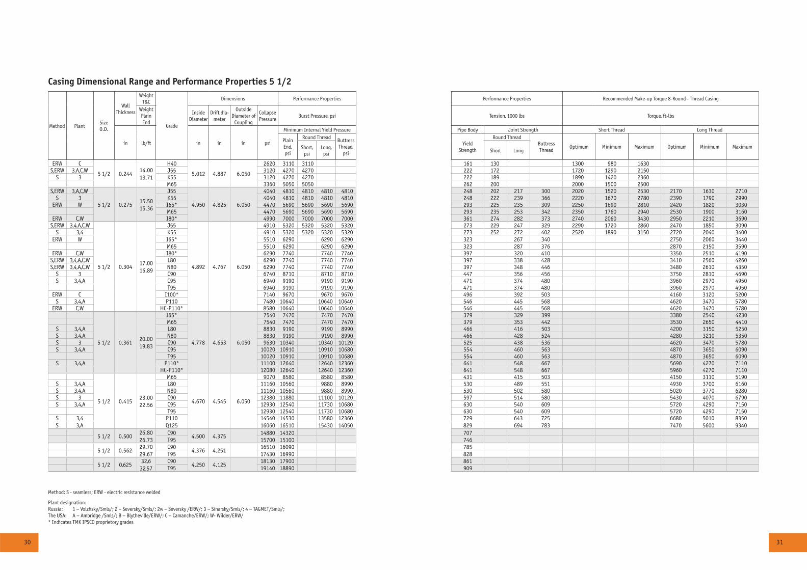
Casing Dimensional Range and Performance Properties 5 1/2
Method PlantSize O.D.
WallThickness
WeightT&C
Grade
Dimensions Performance Properties Performance Properties Recommended Make-up Torque 8-Round - Thread Casing
Weight Plain End
Inside Diameter
Drift dia-meter
OutsideDiameter of
Coupling
Collapse Pressure
Burst Pressure, psi Tension, 1000 lbs Torque, ft-lbs
in lb/ft in in in psi
Minimum Internal Yield Pressure Pipe Body Joint Strength Short Thread Long Thread
PlainEnd,psi
Round Thread Buttress Thread,
psi
Yield Strength
Round ThreadButtress Thread
Optimum Minimum Maximum Optimum Minimum MaximumShort,psi
Long,psi
Short Long
ERW C
5 1/2 0.24414.0013.71
H40
5.012 4.887 6.050
2620 3110 3110 161 130 1300 980 1630S,ERW 3,A,C,W J55 3120 4270 4270 222 172 1720 1290 2150
S 3 K55 3120 4270 4270 222 189 1890 1420 2360M65 3360 5050 5050 262 200 2000 1500 2500
S,ERW 3,A,C,W
5 1/2 0.27515.5015.36
J55
4.950 4.825 6.050
4040 4810 4810 4810 4810 248 202 217 300 2020 1520 2530 2170 1630 2710S 3 K55 4040 4810 4810 4810 4810 248 222 239 366 2220 1670 2780 2390 1790 2990
ERW W I65* 4470 5690 5690 5690 5690 293 225 235 309 2250 1690 2810 2420 1820 3030M65 4470 5690 5690 5690 5690 293 235 253 342 2350 1760 2940 2530 1900 3160
ERW C,W I80* 4990 7000 7000 7000 7000 361 274 282 373 2740 2060 3430 2950 2210 3690S,ERW 3,4,A,C,W
5 1/2 0.30417.0016.89
J55
4.892 4.767 6.050
4910 5320 5320 5320 5320 273 229 247 329 2290 1720 2860 2470 1850 3090S 3,4 K55 4910 5320 5320 5320 5320 273 252 272 402 2520 1890 3150 2720 2040 3400
ERW W I65* 5510 6290 6290 6290 323 267 340 2750 2060 3440M65 5510 6290 6290 6290 323 287 376 2870 2150 3590
ERW C,W I80* 6290 7740 7740 7740 397 320 410 3350 2510 4190S,ERW 3,4,A,C,W L80 6290 7740 7740 7740 397 338 428 3410 2560 4260S,ERW 3,4,A,C,W N80 6290 7740 7740 7740 397 348 446 3480 2610 4350
S 3 C90 6740 8710 8710 8710 447 356 456 3750 2810 4690S 3,4,A C95 6940 9190 9190 9190 471 374 480 3960 2970 4950
T95 6940 9190 9190 9190 471 374 480 3960 2970 4950ERW C I100* 7140 9670 9670 9670 496 392 503 4160 3120 5200
S 3,4,A P110 7480 10640 10640 10640 546 445 568 4620 3470 5780ERW C,W HC-P110* 8580 10640 10640 10640 546 445 568 4620 3470 5780
5 1/2 0.36120.0019.83
I65*
4.778 4.653 6.050
7540 7470 7470 7470 379 329 399 3380 2540 4230M65 7540 7470 7470 7470 379 353 442 3530 2650 4410
S 3,4,A L80 8830 9190 9190 8990 466 416 503 4200 3150 5250S 3,4,A N80 8830 9190 9190 8990 466 428 524 4280 3210 5350S 3 C90 9630 10340 10340 10120 525 438 536 4620 3470 5780S 3,4,A C95 10020 10910 10910 10680 554 460 563 4870 3650 6090
T95 10020 10910 10910 10680 554 460 563 4870 3650 6090S 3,4,A P110* 11100 12640 12640 12360 641 548 667 5690 4270 7110
HC-P110* 12080 12640 12640 12360 641 548 667 5960 4270 7110
5 1/2 0.41523.0022.56
M65
4.670 4.545 6.050
9070 8580 8580 8580 431 415 503 4150 3110 5190S 3,4,A L80 11160 10560 9880 8990 530 489 551 4930 3700 6160S 3,4,A N80 11160 10560 9880 8990 530 502 580 5020 3770 6280S 3 C90 12380 11880 11100 10120 597 514 580 5430 4070 6790S 3,4,A C95 12930 12540 11730 10680 630 540 609 5720 4290 7150
T95 12930 12540 11730 10680 630 540 609 5720 4290 7150S 3,4 P110 14540 14530 13580 12360 729 643 725 6680 5010 8350S 3,A Q125 16060 16510 15430 14050 829 694 783 7470 5600 9340
5 1/2 0.50026.8026.73
C90 4.500 4.375 14880 14320 707T95 15700 15100 746
5 1/2 0.56229.7029.67
C904.376 4.251
16510 16090 785T95 17430 16990 828
5 1/2 0,62532,6
32,57C90
4.250 4.12518130 17900 861
T95 19140 18890 909
Method: S - seamless; ERW - electric resistance welded
Plant designation:Russia: 1 – Volzhsky/Smls/; 2 – Seversky/Smls/; 2w – Seversky /ERW/; 3 – Sinarsky/Smls/; 4 – TAGMET/Smls/;The USA: A – Ambridge /Smls/; B – Blytheville/ERW/; C – Camanche/ERW/; W- Wilder/ERW/ * Indicates TMK IPSCO proprietory grades
32 33
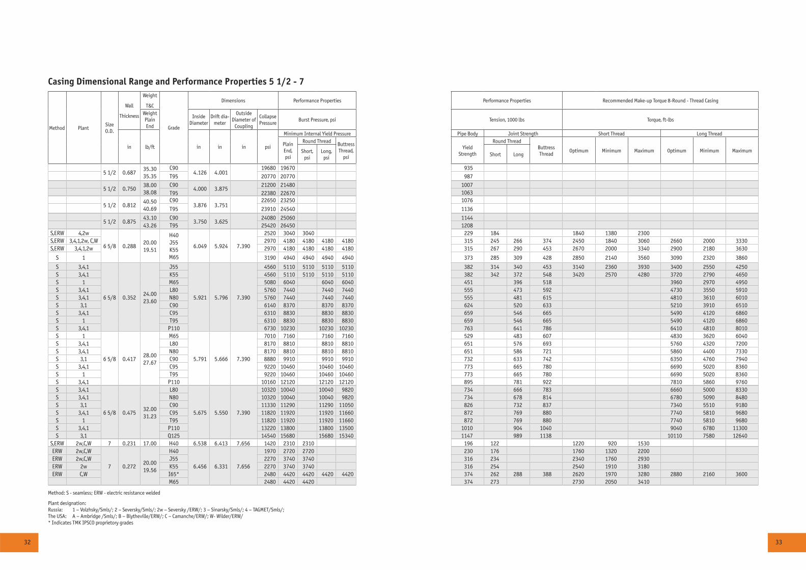
Casing Dimensional Range and Performance Properties 5 1/2 - 7
Method PlantSize O.D.
Wall
Thickness
Weight
T&C
Grade
Dimensions Performance Properties Performance Properties Recommended Make-up Torque 8-Round - Thread Casing
Weight Plain End
Inside Diameter
Drift dia-meter
OutsideDiameter of
Coupling
Collapse Pressure
Burst Pressure, psi Tension, 1000 lbs Torque, ft-lbs
in lb/ft in in in psi
Minimum Internal Yield Pressure Pipe Body Joint Strength Short Thread Long Thread
PlainEnd,psi
Round Thread Buttress Thread,
psi
Yield Strength
Round ThreadButtress Thread
Optimum Minimum Maximum Optimum Minimum MaximumShort,psi
Long,psi
Short Long
5 1/2 0.68735.3035.35
C904.126 4.001
19680 19670 935T95 20770 20770 987
5 1/2 0.75038.0038.08
C904.000 3.875
21200 21480 1007T95 22380 22670 1063
5 1/2 0.81240.5040.69
C903.876 3.751
22650 23250 1076
T95 23910 24540 1136
5 1/2 0.87543.10 C90
3.750 3.62524080 25060 1144
43.26 T95 25420 26450 1208S,ERW 4,2w
6 5/8 0.28820.0019.51
H40J55K55M65
6.049 5.924 7.390
2520 3040 3040 229 184 1840 1380 2300S,ERW 3,4,1,2w, C,W 2970 4180 4180 4180 4180 315 245 266 374 2450 1840 3060 2660 2000 3330S,ERW 3,4,1,2w 2970 4180 4180 4180 4180 315 267 290 453 2670 2000 3340 2900 2180 3630
S 1 3190 4940 4940 4940 4940 373 285 309 428 2850 2140 3560 3090 2320 3860
S 3,4,1
6 5/8 0.35224.0023.60
J55
5.921 5.796 7.390
4560 5110 5110 5110 5110 382 314 340 453 3140 2360 3930 3400 2550 4250S 3,4,1 K55 4560 5110 5110 5110 5110 382 342 372 548 3420 2570 4280 3720 2790 4650S 1 M65 5080 6040 6040 6040 451 396 518 3960 2970 4950S 3,4,1 L80 5760 7440 7440 7440 555 473 592 4730 3550 5910S 3,4,1 N80 5760 7440 7440 7440 555 481 615 4810 3610 6010S 3,1 C90 6140 8370 8370 8370 624 520 633 5210 3910 6510S 3,4,1 C95 6310 8830 8830 8830 659 546 665 5490 4120 6860S 1 T95 6310 8830 8830 8830 659 546 665 5490 4120 6860S 3,4,1 P110 6730 10230 10230 10230 763 641 786 6410 4810 8010S 1
6 5/8 0.41728.0027.67
M65
5.791 5.666 7.390
7010 7160 7160 7160 529 483 607 4830 3620 6040S 3,4,1 L80 8170 8810 8810 8810 651 576 693 5760 4320 7200S 3,4,1 N80 8170 8810 8810 8810 651 586 721 5860 4400 7330S 3,1 C90 8880 9910 9910 9910 732 633 742 6350 4760 7940S 3,4,1 C95 9220 10460 10460 10460 773 665 780 6690 5020 8360S 1 T95 9220 10460 10460 10460 773 665 780 6690 5020 8360S 3,4,1 P110 10160 12120 12120 12120 895 781 922 7810 5860 9760S 3,4,1
6 5/8 0.47532.0031.23
L80
5.675 5.550 7.390
10320 10040 10040 9820 734 666 783 6660 5000 8330S 3,4,1 N80 10320 10040 10040 9820 734 678 814 6780 5090 8480S 3,1 C90 11330 11290 11290 11050 826 732 837 7340 5510 9180S 3,4,1 C95 11820 11920 11920 11660 872 769 880 7740 5810 9680S 1 T95 11820 11920 11920 11660 872 769 880 7740 5810 9680S 3,4,1 P110 13220 13800 13800 13500 1010 904 1040 9040 6780 11300S 3,1 Q125 14540 15680 15680 15340 1147 989 1138 10110 7580 12640
S,ERW 2w,C,W 7 0.231 17.00 H40 6.538 6.413 7.656 1420 2310 2310 196 122 1220 920 1530ERW 2w,C,W
7 0.27220.0019.56
H40
6.456 6.331 7.656
1970 2720 2720 230 176 1760 1320 2200ERW 2w,C,W J55 2270 3740 3740 316 234 2340 1760 2930ERW 2w K55 2270 3740 3740 316 254 2540 1910 3180ERW C,W I65* 2480 4420 4420 4420 4420 374 262 288 388 2620 1970 3280 2880 2160 3600
M65 2480 4420 4420 374 273 2730 2050 3410
Method: S - seamless; ERW - electric resistance welded
Plant designation:Russia: 1 – Volzhsky/Smls/; 2 – Seversky/Smls/; 2w – Seversky /ERW/; 3 – Sinarsky/Smls/; 4 – TAGMET/Smls/;The USA: A – Ambridge /Smls/; B – Blytheville/ERW/; C – Camanche/ERW/; W- Wilder/ERW/ * Indicates TMK IPSCO proprietory grades
34 35
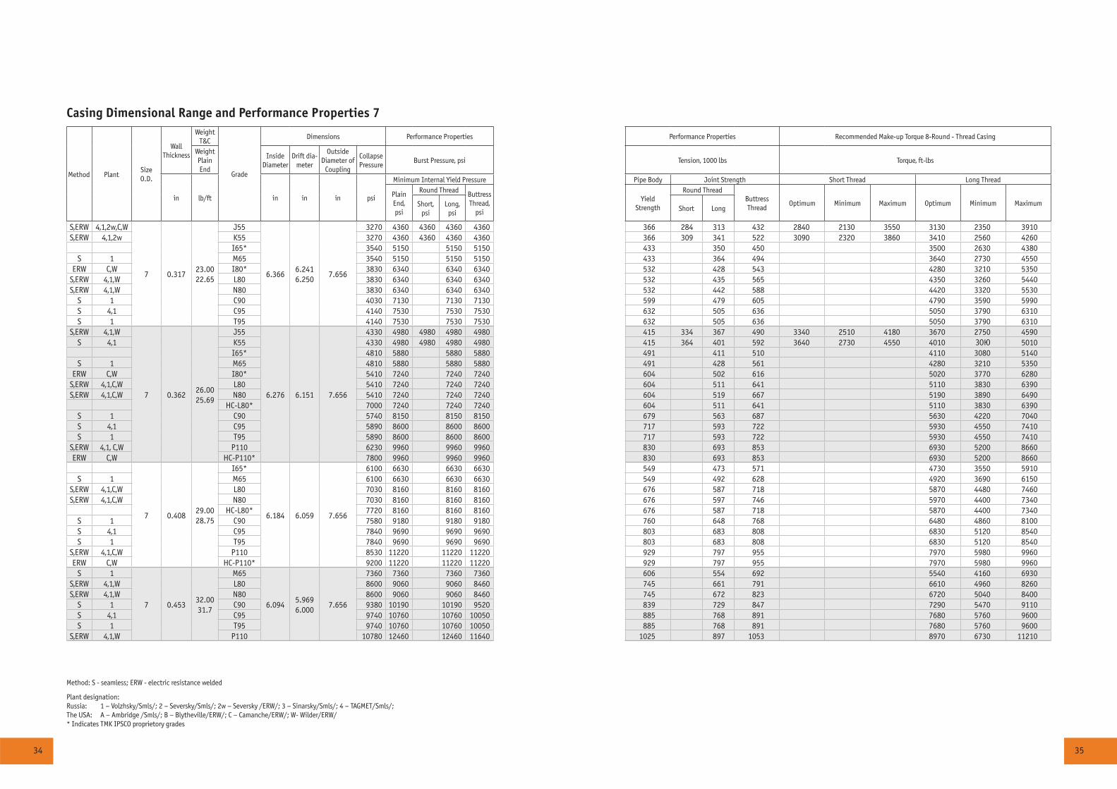
Casing Dimensional Range and Performance Properties 7
Method PlantSize O.D.
WallThickness
WeightT&C
Grade
Dimensions Performance Properties Performance Properties Recommended Make-up Torque 8-Round - Thread Casing
Weight Plain End
Inside Diameter
Drift dia-meter
OutsideDiameter of
Coupling
Collapse Pressure
Burst Pressure, psi Tension, 1000 lbs Torque, ft-lbs
in lb/ft in in in psi
Minimum Internal Yield Pressure Pipe Body Joint Strength Short Thread Long Thread
PlainEnd,psi
Round Thread Buttress Thread,
psi
Yield Strength
Round ThreadButtress Thread
Optimum Minimum Maximum Optimum Minimum MaximumShort,psi
Long,psi
Short Long
S,ERW 4,1,2w,C,W
7 0.31723.0022.65
J55
6.3666.2416.250
7.656
3270 4360 4360 4360 4360 366 284 313 432 2840 2130 3550 3130 2350 3910S,ERW 4,1,2w K55 3270 4360 4360 4360 4360 366 309 341 522 3090 2320 3860 3410 2560 4260
I65* 3540 5150 5150 5150 433 350 450 3500 2630 4380S 1 M65 3540 5150 5150 5150 433 364 494 3640 2730 4550
ERW C,W I80* 3830 6340 6340 6340 532 428 543 4280 3210 5350S,ERW 4,1,W L80 3830 6340 6340 6340 532 435 565 4350 3260 5440S,ERW 4,1,W N80 3830 6340 6340 6340 532 442 588 4420 3320 5530
S 1 C90 4030 7130 7130 7130 599 479 605 4790 3590 5990S 4,1 C95 4140 7530 7530 7530 632 505 636 5050 3790 6310S 1 T95 4140 7530 7530 7530 632 505 636 5050 3790 6310
S,ERW 4,1,W
7 0.36226.0025.69
J55
6.276 6.151 7.656
4330 4980 4980 4980 4980 415 334 367 490 3340 2510 4180 3670 2750 4590S 4,1 K55 4330 4980 4980 4980 4980 415 364 401 592 3640 2730 4550 4010 ÇÎÞ 5010
I65* 4810 5880 5880 5880 491 411 510 4110 3080 5140S 1 M65 4810 5880 5880 5880 491 428 561 4280 3210 5350
ERW C,W I80* 5410 7240 7240 7240 604 502 616 5020 3770 6280S,ERW 4,1,C,W L80 5410 7240 7240 7240 604 511 641 5110 3830 6390S,ERW 4,1,C,W N80 5410 7240 7240 7240 604 519 667 5190 3890 6490
HC-L80* 7000 7240 7240 7240 604 511 641 5110 3830 6390S 1 C90 5740 8150 8150 8150 679 563 687 5630 4220 7040S 4,1 C95 5890 8600 8600 8600 717 593 722 5930 4550 7410S 1 T95 5890 8600 8600 8600 717 593 722 5930 4550 7410
S,ERW 4,1, C,W P110 6230 9960 9960 9960 830 693 853 6930 5200 8660ERW C,W HC-P110* 7800 9960 9960 9960 830 693 853 6930 5200 8660
7 0.40829.0028.75
I65*
6.184 6.059 7.656
6100 6630 6630 6630 549 473 571 4730 3550 5910S 1 M65 6100 6630 6630 6630 549 492 628 4920 3690 6150
S,ERW 4,1,C,W L80 7030 8160 8160 8160 676 587 718 5870 4480 7460S,ERW 4,1,C,W N80 7030 8160 8160 8160 676 597 746 5970 4400 7340
HC-L80* 7720 8160 8160 8160 676 587 718 5870 4400 7340S 1 C90 7580 9180 9180 9180 760 648 768 6480 4860 8100S 4,1 C95 7840 9690 9690 9690 803 683 808 6830 5120 8540S 1 T95 7840 9690 9690 9690 803 683 808 6830 5120 8540
S,ERW 4,1,C,W P110 8530 11220 11220 11220 929 797 955 7970 5980 9960ERW C,W HC-P110* 9200 11220 11220 11220 929 797 955 7970 5980 9960
S 1
7 0.45332.0031.7
M65
6.0945.9696.000
7.656
7360 7360 7360 7360 606 554 692 5540 4160 6930S,ERW 4,1,W L80 8600 9060 9060 8460 745 661 791 6610 4960 8260S,ERW 4,1,W N80 8600 9060 9060 8460 745 672 823 6720 5040 8400
S 1 C90 9380 10190 10190 9520 839 729 847 7290 5470 9110S 4,1 C95 9740 10760 10760 10050 885 768 891 7680 5760 9600S 1 T95 9740 10760 10760 10050 885 768 891 7680 5760 9600
S,ERW 4,1,W P110 10780 12460 12460 11640 1025 897 1053 8970 6730 11210
Method: S - seamless; ERW - electric resistance welded
Plant designation:Russia: 1 – Volzhsky/Smls/; 2 – Seversky/Smls/; 2w – Seversky /ERW/; 3 – Sinarsky/Smls/; 4 – TAGMET/Smls/;The USA: A – Ambridge /Smls/; B – Blytheville/ERW/; C – Camanche/ERW/; W- Wilder/ERW/ * Indicates TMK IPSCO proprietory grades
36 37
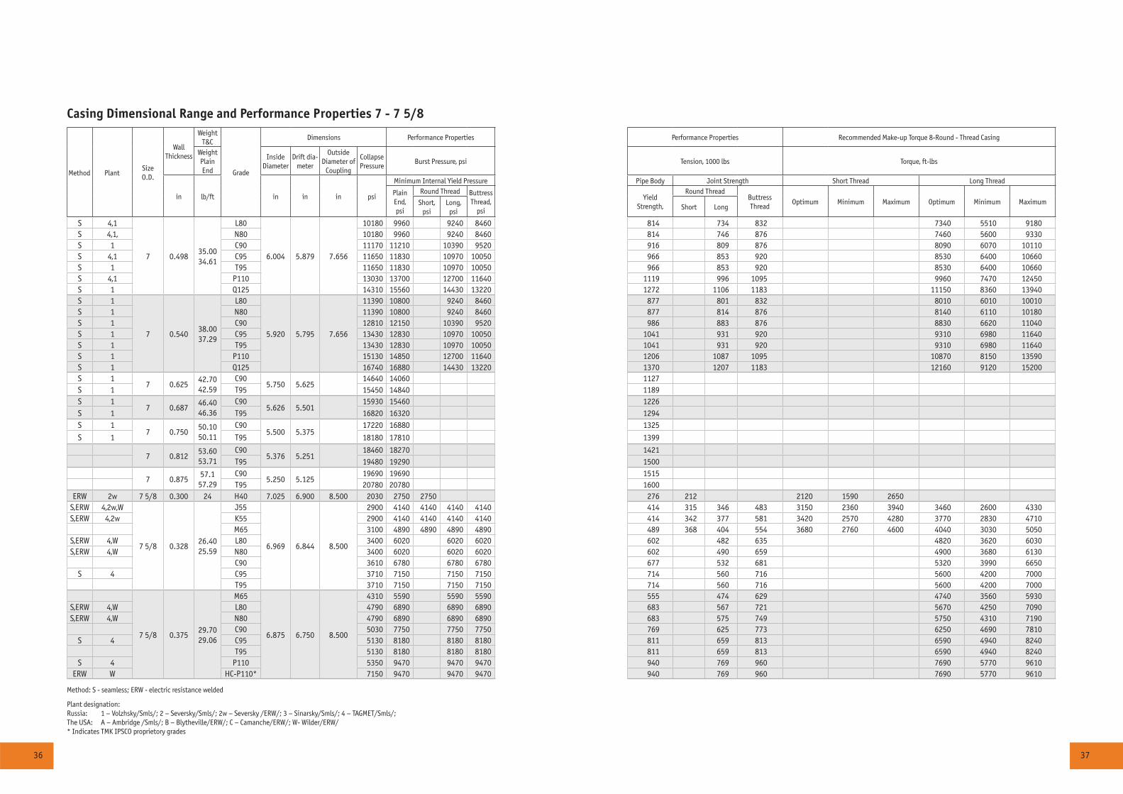
Casing Dimensional Range and Performance Properties 7 - 7 5/8
Method PlantSize O.D.
WallThickness
WeightT&C
Grade
Dimensions Performance Properties Performance Properties Recommended Make-up Torque 8-Round - Thread Casing
Weight Plain End
Inside Diameter
Drift dia-meter
OutsideDiameter of
Coupling
Collapse Pressure
Burst Pressure, psi Tension, 1000 lbs Torque, ft-lbs
in lb/ft in in in psi
Minimum Internal Yield Pressure Pipe Body Joint Strength Short Thread Long Thread
PlainEnd,psi
Round Thread Buttress Thread,
psi
Yield Strength,
Round ThreadButtress Thread
Optimum Minimum Maximum Optimum Minimum MaximumShort,psi
Long,psi
Short Long
S 4,1
7 0.49835.0034.61
L80
6.004 5.879 7.656
10180 9960 9240 8460 814 734 832 7340 5510 9180S 4,1, N80 10180 9960 9240 8460 814 746 876 7460 5600 9330S 1 C90 11170 11210 10390 9520 916 809 876 8090 6070 10110S 4,1 C95 11650 11830 10970 10050 966 853 920 8530 6400 10660S 1 T95 11650 11830 10970 10050 966 853 920 8530 6400 10660S 4,1 P110 13030 13700 12700 11640 1119 996 1095 9960 7470 12450S 1 Q125 14310 15560 14430 13220 1272 1106 1183 11150 8360 13940S 1
7 0.54038.0037.29
L80
5.920 5.795 7.656
11390 10800 9240 8460 877 801 832 8010 6010 10010S 1 N80 11390 10800 9240 8460 877 814 876 8140 6110 10180S 1 C90 12810 12150 10390 9520 986 883 876 8830 6620 11040S 1 C95 13430 12830 10970 10050 1041 931 920 9310 6980 11640S 1 T95 13430 12830 10970 10050 1041 931 920 9310 6980 11640S 1 P110 15130 14850 12700 11640 1206 1087 1095 10870 8150 13590S 1 Q125 16740 16880 14430 13220 1370 1207 1183 12160 9120 15200S 1
7 0.62542.7042.59
C905.750 5.625
14640 14060 1127S 1 T95 15450 14840 1189S 1
7 0.68746.4046.36
C905.626 5.501
15930 15460 1226S 1 T95 16820 16320 1294S 1
7 0.75050.1050.11
C905.500 5.375
17220 16880 1325
S 1 T95 18180 17810 1399
7 0.81253.6053.71
C905.376 5.251
18460 18270 1421T95 19480 19290 1500
7 0.87557.1
57.29C90
5.250 5.12519690 19690 1515
T95 20780 20780 1600ERW 2w 7 5/8 0.300 24 H40 7.025 6.900 8.500 2030 2750 2750 276 212 2120 1590 2650
S,ERW 4,2w,W
7 5/8 0.32826.4025.59
J55
6.969 6.844 8.500
2900 4140 4140 4140 4140 414 315 346 483 3150 2360 3940 3460 2600 4330S,ERW 4,2w K55 2900 4140 4140 4140 4140 414 342 377 581 3420 2570 4280 3770 2830 4710
M65 3100 4890 4890 4890 4890 489 368 404 554 3680 2760 4600 4040 3030 5050S,ERW 4,W L80 3400 6020 6020 6020 602 482 635 4820 3620 6030S,ERW 4,W N80 3400 6020 6020 6020 602 490 659 4900 3680 6130
C90 3610 6780 6780 6780 677 532 681 5320 3990 6650S 4 C95 3710 7150 7150 7150 714 560 716 5600 4200 7000
T95 3710 7150 7150 7150 714 560 716 5600 4200 7000
7 5/8 0.37529.7029.06
M65
6.875 6.750 8.500
4310 5590 5590 5590 555 474 629 4740 3560 5930S,ERW 4,W L80 4790 6890 6890 6890 683 567 721 5670 4250 7090S,ERW 4,W N80 4790 6890 6890 6890 683 575 749 5750 4310 7190
C90 5030 7750 7750 7750 769 625 773 6250 4690 7810S 4 C95 5130 8180 8180 8180 811 659 813 6590 4940 8240
T95 5130 8180 8180 8180 811 659 813 6590 4940 8240S 4 P110 5350 9470 9470 9470 940 769 960 7690 5770 9610
ERW W HC-P110* 7150 9470 9470 9470 940 769 960 7690 5770 9610
Method: S - seamless; ERW - electric resistance welded
Plant designation:Russia: 1 – Volzhsky/Smls/; 2 – Seversky/Smls/; 2w – Seversky /ERW/; 3 – Sinarsky/Smls/; 4 – TAGMET/Smls/;The USA: A – Ambridge /Smls/; B – Blytheville/ERW/; C – Camanche/ERW/; W- Wilder/ERW/ * Indicates TMK IPSCO proprietory grades
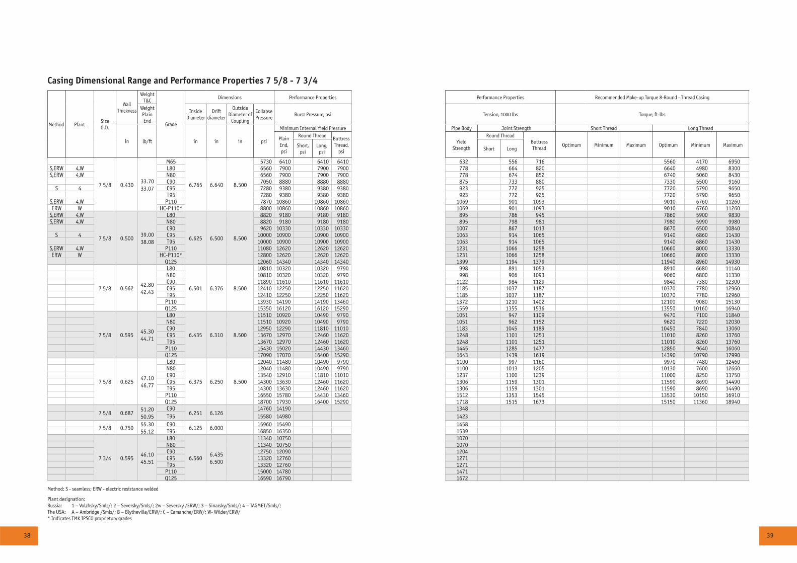
38 39
Casing Dimensional Range and Performance Properties 7 5/8 - 7 3/4
Method PlantSize O.D.
WallThickness
WeightT&C
Grade
Dimensions Performance Properties Performance Properties Recommended Make-up Torque 8-Round - Thread Casing
Weight Plain End
Inside Diameter
Drift diameter
OutsideDiameter of
Coupling
Collapse Pressure
Burst Pressure, psi Tension, 1000 lbs Torque, ft-lbs
in lb/ft in in in psi
Minimum Internal Yield Pressure Pipe Body Joint Strength Short Thread Long Thread
PlainEnd,psi
Round Thread Buttress Thread,
psi
Yield Strength
Round ThreadButtress Thread
Optimum Minimum Maximum Optimum Minimum MaximumShort,psi
Long,psi
Short Long
7 5/8 0.43033.7033.07
M65
6.765 6.640 8.500
5730 6410 6410 6410 632 556 716 5560 4170 6950S,ERW 4,W L80 6560 7900 7900 7900 778 664 820 6640 4980 8300S,ERW 4,W N80 6560 7900 7900 7900 778 674 852 6740 5060 8430
C90 7050 8880 8880 8880 875 733 880 7330 5500 9160S 4 C95 7280 9380 9380 9380 923 772 925 7720 5790 9650
T95 7280 9380 9380 9380 923 772 925 7720 5790 9650S,ERW 4,W P110 7870 10860 10860 10860 1069 901 1093 9010 6760 11260ERW W HC-P110* 8800 10860 10860 10860 1069 901 1093 9010 6760 11260
S,ERW 4,W
7 5/8 0.50039.0038.08
L80
6.625 6.500 8.500
8820 9180 9180 9180 895 786 945 7860 5900 9830S,ERW 4,W N80 8820 9180 9180 9180 895 798 981 7980 5990 9980
C90 9620 10330 10330 10330 1007 867 1013 8670 6500 10840S 4 C95 10000 10900 10900 10900 1063 914 1065 9140 6860 11430
T95 10000 10900 10900 10900 1063 914 1065 9140 6860 11430S,ERW 4,W P110 11080 12620 12620 12620 1231 1066 1258 10660 8000 13330ERW W HC-P110* 12800 12620 12620 12620 1231 1066 1258 10660 8000 13330
Q125 12060 14340 14340 14340 1399 1194 1379 11940 8960 14930
7 5/8 0.56242.8042.43
L80
6.501 6.376 8.500
10810 10320 10320 9790 998 891 1053 8910 6680 11140N80 10810 10320 10320 9790 998 906 1093 9060 6800 11330C90 11890 11610 11610 11610 1122 984 1129 9840 7380 12300C95 12410 12250 12250 11620 1185 1037 1187 10370 7780 12960T95 12410 12250 12250 11620 1185 1037 1187 10370 7780 12960
P110 13930 14190 14190 13460 1372 1210 1402 12100 9080 15130Q125 15350 16120 16120 15290 1559 1355 1536 13550 10160 16940
7 5/8 0.59545.3044.71
L80
6.435 6.310 8.500
11510 10920 10490 9790 1051 947 1109 9470 7100 11840N80 11510 10920 10490 9790 1051 962 1152 9620 7220 12030C90 12950 12290 11810 11010 1183 1045 1189 10450 7840 13060C95 13670 12970 12460 11620 1248 1101 1251 11010 8260 13760T95 13670 12970 12460 11620 1248 1101 1251 11010 8260 13760
P110 15430 15020 14430 13460 1445 1285 1477 12850 9640 16060Q125 17090 17070 16400 15290 1643 1439 1619 14390 10790 17990
7 5/8 0.62547.1046.77
L80
6.375 6.250 8.500
12040 11480 10490 9790 1100 997 1160 9970 7480 12460N80 12040 11480 10490 9790 1100 1013 1205 10130 7600 12660C90 13540 12910 11810 11010 1237 1100 1239 11000 8250 13750C95 14300 13630 12460 11620 1306 1159 1301 11590 8690 14490T95 14300 13630 12460 11620 1306 1159 1301 11590 8690 14490
P110 16550 15780 14430 13460 1512 1353 1545 13530 10150 16910Q125 18700 17930 16400 15290 1718 1515 1673 15150 11360 18940
7 5/8 0.68751.2050.95
C906.251 6.126
14760 14190 1348T95 15580 14980 1423
7 5/8 0.75055.3055.12
C906.125 6.000
15960 15490 1458T95 16850 16350 1539
7 3/4 0.59546.1045.51
L80
6.5606.4356.500
11340 10750 1070N80 11340 10750 1070C90 12750 12090 1204C95 13320 12760 1271T95 13320 12760 1271
P110 15000 14780 1471Q125 16590 16790 1672
Method: S - seamless; ERW - electric resistance welded
Plant designation:Russia: 1 – Volzhsky/Smls/; 2 – Seversky/Smls/; 2w – Seversky /ERW/; 3 – Sinarsky/Smls/; 4 – TAGMET/Smls/;The USA: A – Ambridge /Smls/; B – Blytheville/ERW/; C – Camanche/ERW/; W- Wilder/ERW/ * Indicates TMK IPSCO proprietory grades
40 41
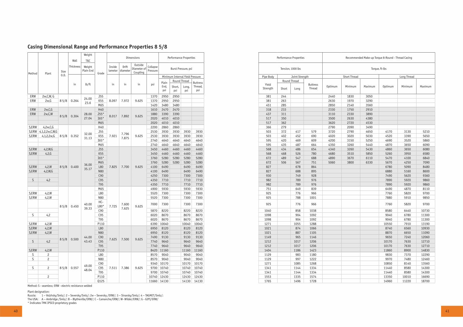
Casing Dimensional Range and Performance Properties 8 5/8
Method PlantSize O.D.
Wall
Thickness
Weight
T&C
Grade
Dimensions Performance Properties Performance Properties Recommended Make-up Torque 8-Round - Thread Casing
Weight Plain End
Inside iameter
Drift diameter
OutsideDiameter of
Coupling
Collapse Pressure
Burst Pressure, psi Tension, 1000 lbs Torque, ft-lbs
in lb/ft in in in psi
Minimum Internal Yield Pressure Pipe Body Joint Strength Short Thread Long Thread
PlainEnd,psi
Round Thread Buttress Thread,
psi
Yield Strength
Round ThreadButtress Thread
Optimum Minimum Maximum Optimum Minimum MaximumShort,psi
Long,psi
Short Long
ERW 2w,C,W, G8 5/8 0.264
24.0023.6
J558.097 7.972 9.625
1370 2950 2950 381 244 2440 1830 3050ERW 2w,G K55 1370 2950 2950 381 263 2630 1970 3290
M65 1420 3480 3480 451 285 2850 2140 3560ERW 2w,C,G
8 5/8 0.30428.0027.04
H40
8.017 7.892 9.625
1610 2470 2470 318 233 2330 1750 2910ERW 2w,C,W J55* 1880 3390 3390 437 311 3110 2330 3890
I65* 2020 4010 4010 517 350 3500 2630 4380M65 2020 4010 4010 517 362 3620 2720 4530
S,ERW 4,2w,C,G
8 5/8 0.35232.0031.13
H40
7.9217.7967.875
9.625
2200 2860 2860 366 279 2790 2090 3490S,ERW 4,1,2,2w,C,W,G J55 2530 3930 3930 3930 3930 503 372 417 579 3720 2790 4650 4170 3130 5210S,ERW 4,1,2,2w,G K55 2530 3930 3930 3930 3930 503 402 452 690 4020 3020 5030 4520 3390 5650
I65* 2740 4640 4640 4640 4640 595 420 469 609 4200 3150 5250 4690 3520 5860M65 2740 4640 4640 4640 4640 595 435 487 664 4350 3260 5440 4870 3650 6090
S,ERW 4,2,W,G
8 5/8 0.40036.0035.17
J55
7.825 7.700 9.625
3450 4460 4460 4460 4460 568 434 486 654 4340 3260 5430 4860 3650 6080S,ERW 4,2,G K55 3450 4460 4460 4460 4460 568 468 526 780 4680 3510 5850 5260 3950 6580
I65* 3760 5280 5280 5280 5280 672 489 547 688 4890 3670 6110 5470 4100 6840M65 3760 5280 5280 5280 5280 672 506 567 751 5060 3800 6330 5670 4250 7090
S,ERW 4,2,W L80 4100 6490 6490 6490 827 678 864 6780 5090 8480S,ERW 4,2,W,G N80 4100 6490 6490 6490 827 688 895 6880 5160 8600
C90 4250 7300 7300 7300 930 749 928 7490 5620 9360S 4,2 C95 4350 7710 7710 7710 982 789 976 7890 5920 9860
T95 4350 7710 7710 7710 982 789 976 7890 5920 9860
8 5/8 0.45040.0039.33
M65
7.7257.6007.625
9.625
4900 5930 5930 5930 751 649 839 6490 4870 8110S,ERW 4,2,W L80 5520 7300 7300 7300 925 776 966 7760 5820 9700S,ERW 4,2,W N80 5520 7300 7300 7300 925 788 1001 7880 5910 9850
HC-L80*
7000 7300 7300 7300 925 776 966 7760 5820 9700
C90 5870 8220 8220 8220 1040 858 1038 8580 6440 10730S 4,2 C95 6020 8670 8670 8670 1098 904 1092 9040 6780 11300
T95 6020 8670 8670 8670 1098 904 1092 9040 6780 11300S,ERW 4,2,W P110 6390 10040 10040 10040 1271 1055 1288 10550 7910 13190S,ERW 4,2,W
8 5/8 0.50044.0043.43
L80
7.625 7.500 9.625
6950 8120 8120 8120 1021 874 1066 8740 6560 10930S,ERW 4,2,W N80 6950 8120 8120 8120 1021 887 1105 8870 6650 11090
C90 7490 9130 9130 9130 1149 965 1146 9650 7240 12060S 4,2 C95 7740 9640 9640 9640 1212 1017 1206 10170 7630 12710
T95 7740 9640 9640 9640 1212 1017 1206 10170 7630 12710S,ERW 4,2,W P110 8420 11160 11160 11160 1404 1186 1423 11860 8900 14830
S 2
8 5/8 0.55749.0048.04
L80
7.511 7.386 9.625
8570 9040 9040 9040 1129 983 1180 9830 7370 12290S 2 N80 8570 9040 9040 9040 1129 997 1222 9970 7480 12460
C90 9340 10170 10170 10170 1271 1085 1268 10850 8140 13560S 2 C95 9700 10740 10740 10740 1341 1144 1334 11440 8580 14300
T95 9700 10740 10740 10740 1341 1144 1334 11440 8580 143002 P110 10740 12430 12430 12430 1553 1335 1574 13350 10010 16690
Q125 11660 14130 14130 14130 1765 1496 1728 14960 11220 18700Method: S - seamless; ERW - electric resistance welded
Plant designation:Russia: 1 – Volzhsky/Smls/; 2 – Seversky/Smls/; 2w – Seversky /ERW/; 3 – Sinarsky/Smls/; 4 – TAGMET/Smls/;The USA: A – Ambridge /Smls/; B – Blytheville/ERW/; C – Camanche/ERW/; W- Wilder/ERW/; G - GIPI/ERW/ * Indicates TMK IPSCO proprietory grades
42 43
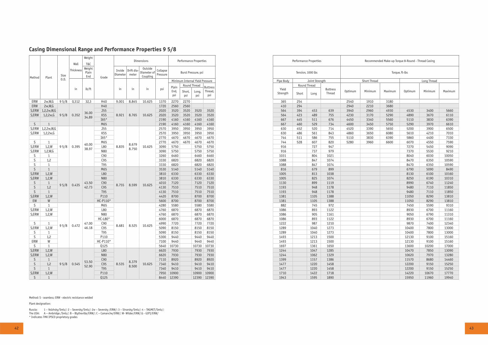
Casing Dimensional Range and Performance Properties 9 5/8
Method PlantSize O.D.
Wall
Thickness
Weight
T&C
Grade
Dimensions Performance Properties Performance Properties Recommended Make-up Torque 8-Round - Thread Casing
Weight Plain End
Inside Diameter
Drift dia-meter
OutsideDiameter of
Coupling
Collapse Pressure
Burst Pressure, psi Tension, 1000 lbs Torque, ft-lbs
in lb/ft in in in psi
Minimum Internal Yield Pressure Pipe Body Joint Strength Short Thread Long Thread
PlainEnd,psi
Round Thread Buttress Thread,
psi
Yield Strength
Round ThreadButtress Thread
Optimum Minimum Maximum Optimum Minimum MaximumShort,psi
Long,psi
Short Long
ERW 2w,W,G 9 5/8 0,312 32,3 H40 9.001 8.845 10.625 1370 2270 2270 365 254 2540 1910 3180ERW 2w,W,G
9 5/8 0.35236.0034.89
H40
8.921 8.765 10.625
1720 2560 2560 410 294 2940 2210 3680S,ERW 1,2,2w,W,G J55 2020 3520 3520 3520 3520 564 394 453 639 3940 2960 4930 4530 3400 5660S,ERW 1,2,2w,G K55 2020 3520 3520 3520 3520 564 423 489 755 4230 3170 5290 4890 3670 6110
I65* 2190 4160 4160 4160 4160 667 445 511 676 4450 3340 5560 5110 3830 6390S 1 M65 2190 4160 4160 4160 4160 667 460 529 734 4600 3450 5750 5290 3970 6610
S,ERW 1,2,2w,W,G
9 5/8 0.39540.0038.97
J55
8.8358.6798.750
10.625
2570 3950 3950 3950 3950 630 452 520 714 4520 3390 5650 5200 3900 6500S,ERW 1,2,2w,G K55 2570 3950 3950 3950 3950 630 486 561 843 4860 3650 6080 5610 4210 7010
I65* 2770 4670 4670 4670 4670 744 511 586 755 5110 3830 6390 5860 4400 7330S 1 M65 2770 4670 4670 4670 4670 744 528 607 820 5280 3960 6600 6070 4550 7590
S,ERW 1,2,W L80 3090 5750 5750 5750 916 727 947 7270 5450 9090S,ERW 1,2,W,G N80 3090 5750 5750 5750 916 737 979 7370 5530 9210
S 1 C90 3260 6460 6460 6460 1031 804 1021 8040 6030 10050S 1,2 C95 3330 6820 6820 6820 1088 847 1074 8470 6350 10590S 1 T95 3330 6820 6820 6820 1088 847 1074 8470 6350 10590S 1
9 5/8 0.43543.5042.73
M65
8.755 8.599 10.625
3530 5140 5140 5140 816 679 899 6790 5090 8490S,ERW 1,2,W L80 3810 6330 6330 6330 1005 813 1038 8130 6100 10160S,ERW 1,2,W N80 3810 6330 6330 6330 1005 825 1074 8250 6190 10310
S 1 C90 4010 7120 7120 7120 1130 899 1119 8990 6740 11240S 1,2 C95 4130 7510 7510 7510 1193 948 1178 9480 7110 11850S 1 T95 4130 7510 7510 7510 1193 948 1178 9480 7110 11850
S,ERW 1,2,W P110 4420 8700 8700 8700 1381 1105 1388 11050 8290 13810EW W HC-P110* 5600 8700 8700 8700 1381 1105 1388 11050 8290 13810S 1
9 5/8 0.47247.0046.18
M65
8.681 8.525 10.625
4280 5580 5580 5580 882 745 972 7450 5590 9310S,ERW 1,2,W L80 4760 6870 6870 6870 1086 893 1122 8930 6700 11160S,ERW 1,2,W N80 4760 6870 6870 6870 1086 905 1161 9050 6790 11310
HC-L80* 6000 6870 6870 6870 1086 893 1122 8930 6700 11160S 1 C90 4990 7720 7720 7720 1222 987 1210 9870 7400 12340
S,ERW 1,2,W C95 5090 8150 8150 8150 1289 1040 1273 10400 7800 13000S 1 T95 5090 8150 8150 8150 1289 1040 1273 10400 7800 13000S 1,2 P110 5300 9440 9440 9440 1493 1213 1500 12130 9100 15160
ERW W HC-P110* 7100 9440 9440 9440 1493 1213 1500 12130 9100 15160S 1 Q125 5640 10730 10730 10730 1697 1361 1650 13600 10200 17000
S,ERW 1,2,W
9 5/8 0.54553.5052.90
L80
8.5358.3798.500
10.625
6620 7930 7930 7930 1244 1047 1285 10470 7850 13090S,ERW 1,2,W N80 6620 7930 7930 7930 1244 1062 1329 10620 7970 13280
S 1 C90 7110 8920 8920 8920 1399 1157 1386 11570 8680 14460S 1,2 C95 7340 9410 9410 9410 1477 1220 1458 12200 9150 15250S 1 T95 7340 9410 9410 9410 1477 1220 1458 12200 9150 15250
S,ERW 1,2,W P110 7950 10900 10900 10900 1710 1422 1718 14220 10670 17770S 1 Q125 8440 12390 12390 12390 1943 1595 1890 15950 11960 19940
Method: S - seamless; ERW - electric resistance welded
Plant designation:
Russia: 1 – Volzhsky/Smls/; 2 – Seversky/Smls/; 2w – Seversky /ERW/; 3 – Sinarsky/Smls/; 4 – TAGMET/Smls/;The USA: A – Ambridge /Smls/; B – Blytheville/ERW/; C – Camanche/ERW/; W- Wilder/ERW/;G - GIPI/ERW/ * Indicates TMK IPSCO proprietory grades

44 45
Casing Dimensional Range and Performance Properties 9 5/8 - 10 3/4
Method PlantSize O.D.
Wall
Thickness
Weight
T&CGrade
Dimensions Performance Properties Performance Properties Recommended Make-up Torque 8-Round - Thread Casing
Weight Plain End
Inside Diameter
Drift dia-meter
OutsideDiameter of
Coupling
Collapse Pressure
Burst Pressure, psi Tension, 1000 lbs Torque, ft-lbs
in lb/ft in in in psi
Minimum Internal Yield Pressure Pipe Body Joint Strength Short Thread Long Thread
PlainEnd,psi
Round Thread Buttress Thread,
psi
Yield Strength
Round ThreadButtress Thread
Optimum Minimum Maximum Optimum Minimum MaximumShort,psi
Long,psi
Short Long
S 1,2
9 5/8 0.59558.4057.44
L80
8.4358.2798.375
10.625
7890 8650 8650 8650 1350 1151 1396 11510 8630 14390S 1,2 N80 7890 8650 8650 8650 1350 1167 1443 11670 8750 14590S 1 C90 8560 9740 9740 9740 1519 1272 1505 12720 9540 15900S 1,2 C95 8880 10280 10280 10280 1604 1341 1583 13410 10060 16760S 1 T95 8880 10280 10280 10280 1604 1341 1583 13410 10060 16760S 1,2 P110 9770 11900 11900 11900 1857 1564 1865 15640 11730 19550S 1 Q125 10540 13520 13520 13520 2110 1754 2052 17540 13160 21930
9 5/8 0.60959.4058.70
C908.407 8.251 10.625
8970 9970 1552T95 9320 10520 1639
9 5/8 0.67264.9064.32
C908.281 8.125 10.625
10800 11000 1701T95 11260 11610 1796
9 5/8 0.73470.3069.76
C908.157 8.001 10.625
12600 12010 1845T95 13170 12680 1948
9 5/8 0.79775.6075.21
C908.031 7.875 10.625
13670 13040 1989T95 14430 13770 2100
ERW 2w,G 10 3/4 0.279 32.75 H40 10.192 10.036 11.750 840 1820 1820 367 205 2050 1540 2560ERW 2w,G
10 3/4 0.35040.5038.91
H40
10.050 9.894 11.750
1390 2280 2280 2280 457 314 3140 2360 3930S,ERW 2,2w,W,G J55 1580 3130 3130 3130 629 420 700 4200 3150 5250S,ERW 2,2w,G K55 1580 3130 3130 3130 629 450 819 4500 3380 5630
M65 1670 3700 3700 3700 743 491 806 4910 3680 6140S,ERW 2,2w,W,G
10 3/4 0.40045.5044.26
J559.950
9.7949.875
11.7502090 3580 3580 3580 715 493 796 4930 3700 6160
S,ERW 2,2w,G K55 2090 3580 3580 3580 715 528 931 5280 3960 6600M65 2270 4230 4230 4230 845 576 916 5760 4320 7200
S,ERW 2,2w,W,G
10 3/4 0.45051.0049.55
J55
9.850 9.694 11.750
2700 4030 4030 4030 801 565 891 5650 4240 7060S,ERW 2,2w,G K55 2700 4030 4030 4030 801 606 1043 6060 4550 7580
M65 2870 4760 4760 4760 946 661 1026 6610 4960 8260S,ERW 2,W L80 3220 5860 5860 5860 1165 794 1190 7940 5960 9930S,ERW 2,W,G N80 3220 5860 5860 5860 1165 804 1228 8040 6030 10050
S 2 C90 3400 6590 6590 6590 1311 879 1287 8790 6590 10990C95 3480 6960 6960 6960 1383 927 1354 9270 6950 11590T95 3480 6960 6960 6960 1383 927 1354 9270 6950 11590
S,ERW 2,W P110 3660 8060 8060 8060 1602 1080 1594 10790 8090 13490
10 3/4 0.49555.5054.26
M65
9.7609.6049.625
11.750
3690 5240 5240 5240 1037 736 1124 7360 5520 9200S,ERW 2,W L80 4020 6450 6450 6450 1276 884 1303 8840 6630 11050S,ERW 2,W N80 4020 6450 6450 6450 1276 895 1345 8950 6710 11190
C90 4160 7250 7250 7250 1435 979 1409 9790 7340 12240S 2 C95 4290 7660 7660 7660 1515 1032 1483 10320 7740 12900
T95 4290 7660 7660 7660 1515 1032 1483 10320 7740 12900S,ERW 2,W P110 4610 8860 8860 8860 1754 1203 1745 12020 9020 15030
Method: S - seamless; ERW - electric resistance welded
Plant designation:
Russia: 1 – Volzhsky/Smls/; 2 – Seversky/Smls/; 2w – Seversky /ERW/; 3 – Sinarsky/Smls/; 4 – TAGMET/Smls/;The USA: A – Ambridge /Smls/; B – Blytheville/ERW/; C – Camanche/ERW/; W- Wilder/ERW/;G - GIPI/ERW/ * Indicates TMK IPSCO proprietory grades
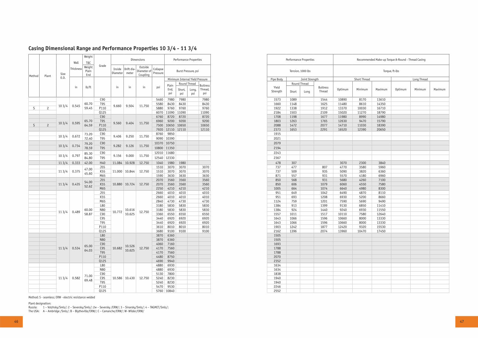
46 47
Casing Dimensional Range and Performance Properties 10 3/4 - 11 3/4
Method PlantSize O.D.
Wall
Thickness
Weight
T&CGrade
Dimensions Performance Properties Performance Properties Recommended Make-up Torque 8-Round - Thread Casing
Weight Plain End
Inside Diameter
Drift dia-meter
OutsideDiameter of
Coupling
Collapse Pressure
Burst Pressure, psi Tension, 1000 lbs Torque, ft-lbs
in lb/ft in in in psi
Minimum Internal Yield Pressure Pipe Body Joint Strength Short Thread Long Thread
PlainEnd,psi
Round Thread Buttress Thread,
psi
Yield Strength
Round ThreadButtress Thread
Optimum Minimum Maximum Optimum Minimum MaximumShort,psi
Long,psi
Short Long
10 3/4 0.54560.7059.45
C90
9.660 9.504 11.750
5460 7980 7980 7980 1573 1089 1544 10890 8170 13610T95 5580 8430 8430 8430 1660 1148 1625 11480 8610 14350
S 2 P110 5880 9760 9760 9760 1922 1338 1912 13370 10030 16710Q125 6070 11090 11090 11090 2184 1503 2109 15020 11270 18790
10 3/4 0.59565.7064.59
C90
9.560 9.404 11.750
6760 8720 8720 8720 1708 1198 1677 11980 8990 14980T95 6960 9200 9200 9200 1803 1263 1765 12630 9470 15790
S 2 P110 7500 10650 10650 10650 2088 1472 2077 14710 11030 18390Q125 7920 12110 12110 12110 2373 1653 2291 16520 12390 20650
10 3/4 0.67273.2072.40
C909.406 9.250 11.750
8760 9850 1915T95 9090 10390 2021
10 3/4 0.73479.2078.59
C909.282 9.126 11.750
10370 10750 2079T95 10800 11350 2194
10 3/4 0.79785.3084.80
C909.156 9.000 11.750
12010 11680 2243T95 12540 12330 2367
11 3/4 0.333 42.00 H40 11.084 10.928 12.750 1040 1980 1980 478 307 3070 2300 3840
11 3/4 0.37547.0045.60
J5511.000 10.844 12.750
1510 3070 3070 3070 737 477 807 4770 3580 5960K55 1510 3070 3070 3070 737 509 935 5090 3820 6360M65 1590 3630 3630 3630 871 557 931 5570 4180 6960
11 3/4 0.43554.0052.62
J5510.880 10.724 12.750
2070 3560 3560 3560 850 568 931 5680 4260 7100K55 2070 3560 3560 3560 850 606 1079 6060 4550 7580M65 2250 4210 4210 4210 1005 664 1074 6640 4980 8300
11 3/4 0.48960.0058.87
J55
10.77210.61610.625
12.750
2660 4010 4010 4010 951 649 1042 6490 4870 8110K55 2660 4010 4010 4010 951 693 1208 6930 5200 8660M65 2840 4730 4730 4730 1124 759 1201 7590 5690 9490L80 3180 5830 5830 5830 1384 913 1399 9130 6850 11410N80 3180 5830 5830 5830 1384 924 1440 9240 6930 11550C90 3360 6550 6550 6550 1557 1011 1517 10110 7580 12640C95 3440 6920 6920 6920 1643 1066 1596 10660 8000 13330T95 3440 6920 6920 6920 1643 1066 1596 10660 8000 13330
P110 3610 8010 8010 8010 1903 1242 1877 12420 9320 15530Q125 3680 9100 9100 9100 2162 1396 2074 13960 10470 17450
11 3/4 0.53465.0064.03
L80
10.68210.52610.625
12.750
3870 6360 1505N80 3870 6360 1505C90 4060 7160 1693C95 4170 7560 1788T95 4170 7560 1788
P110 4480 8750 2070Q125 4690 9940 2352
11 3/4 0.58271.0069.48
L80
10.586 10.430 12.750
4880 6930 1634N80 4880 6930 1634C90 5130 7800 1838C95 5240 8230 1940T95 5240 8230 1940
P110 5470 9530 2246Q125 5760 10840 2552
Method: S - seamless; ERW - electric resistance welded
Plant designation:Russia: 1 – Volzhsky/Smls/; 2 – Seversky/Smls/; 2w – Seversky /ERW/; 3 – Sinarsky/Smls/; 4 – TAGMET/Smls/;The USA: A – Ambridge /Smls/; B – Blytheville/ERW/; C – Camanche/ERW/; W- Wilder/ERW/
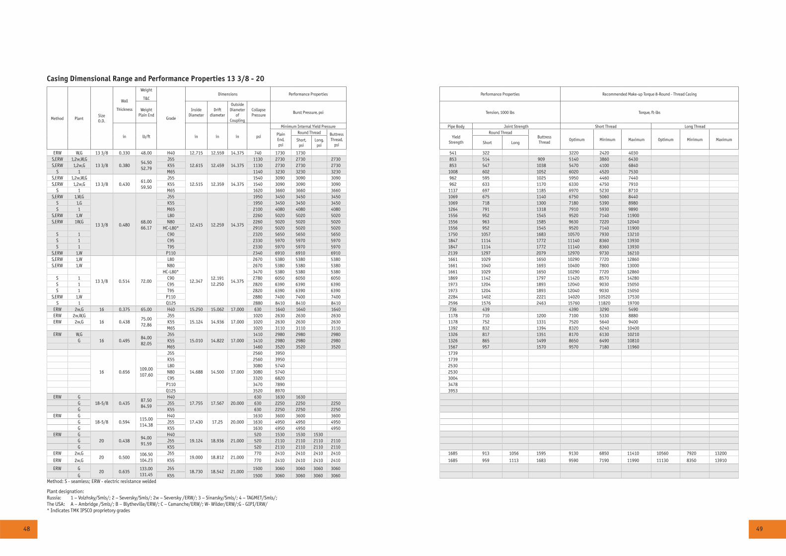
48 49
Casing Dimensional Range and Performance Properties 13 3/8 - 20
Method PlantSize O.D.
Wall
Thickness
Weight
T&C
Grade
Dimensions Performance Properties Performance Properties Recommended Make-up Torque 8-Round - Thread Casing
Weight Plain End
Inside Diameter
Drift diameter
OutsideDiameter
of Coupling
Collapse Pressure
Burst Pressure, psi Tension, 1000 lbs Torque, ft-lbs
in lb/ft in in in psi
Minimum Internal Yield Pressure Pipe Body Joint Strength Short Thread Long Thread
PlainEnd,psi
Round Thread Buttress Thread,
psi
Yield Strength
Round ThreadButtress Thread
Optimum Minimum Maximum Optimum Minimum MaximumShort,psi
Long,psi
Short Long
ERW W,G 13 3/8 0.330 48.00 H40 12.715 12.559 14.375 740 1730 1730 541 322 3220 2420 4030S,ERW 1,2w,W,G
13 3/8 0.38054.5052.79
J5512.615 12.459 14.375
1130 2730 2730 2730 853 514 909 5140 3860 6430S,ERW 1,2w,G K55 1130 2730 2730 2730 853 547 1038 5470 4100 6840
S 1 M65 1140 3230 3230 3230 1008 602 1052 6020 4520 7530S,ERW 1,2w,W,G
13 3/8 0.43061.0059.50
J55 12.515 12.359 14.375
1540 3090 3090 3090 962 595 1025 5950 4460 7440S,ERW 1,2w,G K55 1540 3090 3090 3090 962 633 1170 6330 4750 7910
S 1 M65 1620 3660 3660 3660 1137 697 1185 6970 5230 8710S,ERW 1,W,G
13 3/8 0.48068.0066.17
J55
12.415 12.259 14.375
1950 3450 3450 3450 1069 675 1140 6750 5060 8440S 1,G K55 1950 3450 3450 3450 1069 718 1300 7180 5390 8980S 1 M65 2100 4080 4080 4080 1264 791 1318 7910 5930 9890
S,ERW 1,W L80 2260 5020 5020 5020 1556 952 1545 9520 7140 11900S,ERW 1W,G N80 2260 5020 5020 5020 1556 963 1585 9630 7220 12040
HC-L80* 2910 5020 5020 5020 1556 952 1545 9520 7140 11900S 1 C90 2320 5650 5650 5650 1750 1057 1683 10570 7930 13210S 1 C95 2330 5970 5970 5970 1847 1114 1772 11140 8360 13930S 1 T95 2330 5970 5970 5970 1847 1114 1772 11140 8360 13930
S,ERW 1,W P110 2340 6910 6910 6910 2139 1297 2079 12970 9730 16210S,ERW 1,W
13 3/8 0.514 72.00
L80
12.34712.19112.250
14.375
2670 5380 5380 5380 1661 1029 1650 10290 7720 12860S,ERW 1,W N80 2670 5380 5380 5380 1661 1040 1693 10400 7800 13000
HC-L80* 3470 5380 5380 5380 1661 1029 1650 10290 7720 12860S 1 C90 2780 6050 6050 6050 1869 1142 1797 11420 8570 14280S 1 C95 2820 6390 6390 6390 1973 1204 1893 12040 9030 15050S 1 T95 2820 6390 6390 6390 1973 1204 1893 12040 9030 15050
S,ERW 1,W P110 2880 7400 7400 7400 2284 1402 2221 14020 10520 17530S 1 Q125 2880 8410 8410 8410 2596 1576 2463 15760 11820 19700
ERW 2w,G 16 0.375 65.00 H40 15.250 15.062 17.000 630 1640 1640 1640 736 439 4390 3290 5490ERW 2w,W,G
16 0.43875.0072.86
J5515.124 14.936 17.000
1020 2630 2630 2630 1178 710 1200 7100 5330 8880ERW 2w,G K55 1020 2630 2630 2630 1178 752 1331 7520 5640 9400
M65 1020 3110 3110 3110 1392 832 1394 8320 6240 10400ERW W,G
16 0.49584.0082.05
J5515.010 14.822 17.000
1410 2980 2980 2980 1326 817 1351 8170 6130 10210G K55 1410 2980 2980 2980 1326 865 1499 8650 6490 10810
M65 1460 3520 3520 3520 1567 957 1570 9570 7180 11960
16 0.656109.00107.60
J55
14.688 14.500 17.000
2560 3950 1739K55 2560 3950 1739L80 3080 5740 2530N80 3080 5740 2530C95 3320 6820 3004
P110 3470 7890 3478Q125 3520 8970 3953
ERW G18-5/8 0.435
87.5084.59
H4017.755 17.567 20.000
630 1630 1630G J55 630 2250 2250 2250G K55 630 2250 2250 2250
ERW G18-5/8 0.594
115.00114.38
H4017.430 17.25 20.000
1630 3600 3600 3600G J55 1630 4950 4950 4950G K55 1630 4950 4950 4950
ERW G20 0.438
94.0091.59
H4019.124 18.936 21.000
520 1530 1530 1530G J55 520 2110 2110 2110 2110G K55 520 2110 2110 2110 2110
ERW 2w,G20 0.500
106.50104.23
J5519.000 18.812 21.000
770 2410 2410 2410 2410 1685 913 1056 1595 9130 6850 11410 10560 7920 13200
ERW 2w,G K55 770 2410 2410 2410 2410 1685 959 1113 1683 9590 7190 11990 11130 8350 13910
ERW G20 0.635
133.00131.45
J5518.730 18.542 21.000
1500 3060 3060 3060 3060
G K55 1500 3060 3060 3060 3060Method: S - seamless; ERW - electric resistance welded
Plant designation:Russia: 1 – Volzhsky/Smls/; 2 – Seversky/Smls/; 2w – Seversky /ERW/; 3 – Sinarsky/Smls/; 4 – TAGMET/Smls/;The USA: A – Ambridge /Smls/; B – Blytheville/ERW/; C – Camanche/ERW/; W- Wilder/ERW/;G - GIPI/ERW/ * Indicates TMK IPSCO proprietory grades
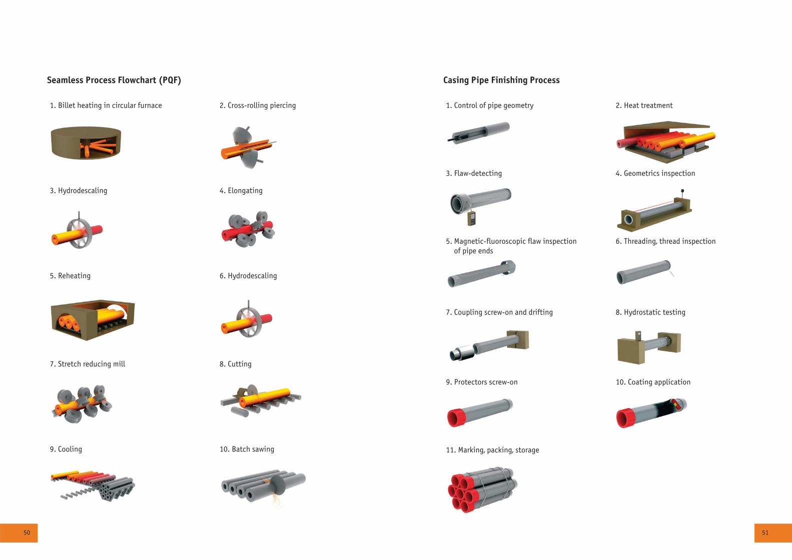
50 51
1. Control of pipe geometry 2. Heat treatment
3. Flaw-detecting 4. Geometrics inspection
5. Magnetic-fluoroscopic flaw inspection of pipe ends
6. Threading, thread inspection
7. Coupling screw-on and drifting 8. Hydrostatic testing
9. Protectors screw-on 10. Coating application
11. Marking, packing, storage
Casing Pipe Finishing Process
1. Billet heating in circular furnace 2. Cross-rolling piercing
3. Hydrodescaling 4. Elongating
5. Reheating 6. Hydrodescaling
7. Stretch reducing mill 8. Cutting
9. Cooling 10. Batch sawing
Seamless Process Flowchart (PQF)
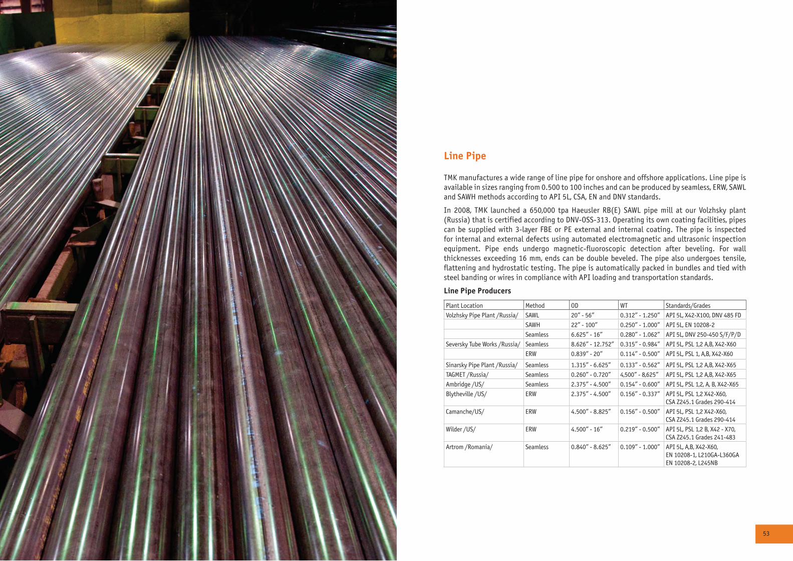
52 53
Line Pipe
TMK manufactures a wide range of line pipe for onshore and offshore applications. Line pipe is available in sizes ranging from 0.500 to 100 inches and can be produced by seamless, ERW, SAWL and SAWH methods according to API 5L, CSA, EN and DNV standards.
In 2008, TMK launched a 650,000 tpa Haeusler RB(E) SAWL pipe mill at our Volzhsky plant (Russia) that is certified according to DNV-OSS-313. Operating its own coating facilities, pipes can be supplied with 3-layer FBE or PE external and internal coating. The pipe is inspected for internal and external defects using automated electromagnetic and ultrasonic inspection equipment. Pipe ends undergo magnetic-fluoroscopic detection after beveling. For wall thicknesses exceeding 16 mm, ends can be double beveled. The pipe also undergoes tensile, flattening and hydrostatic testing. The pipe is automatically packed in bundles and tied with steel banding or wires in compliance with API loading and transportation standards.
Line Pipe Producers
Plant Location Method OD WT Standards/Grades
Volzhsky Pipe Plant /Russia/ SAWL 20” - 56” 0.312” - 1.250” API 5L, X42-X100, DNV 485 FD
SAWH 22” - 100” 0.250” - 1.000” API 5L, EN 10208-2
Seamless 6.625” - 16” 0.280” - 1.062” API 5L, DNV 250-450 S/F/P/D
Seversky Tube Works /Russia/ Seamless 8.626” - 12.752” 0.315” - 0.984” API 5L, PSL 1,2 A,B, X42-X60
ERW 0.839” - 20” 0.114” - 0.500” API 5L, PSL 1, A,B, X42-X60
Sinarsky Pipe Plant /Russia/ Seamless 1.315” - 6.625” 0.133” - 0.562” API 5L, PSL 1,2 A,B, X42-X65
TAGMET /Russia/ Seamless 0.260” - 0.720” 4,500” - 8,625” API 5L, PSL 1,2 A,B, X42-X65
Ambridge /US/ Seamless 2.375” - 4.500” 0.154” - 0.600” API 5L, PSL 1,2, A, B, X42-X65
Blytheville /US/ ERW 2.375” - 4.500” 0.156” - 0.337” API 5L, PSL 1,2 X42-X60,CSA Z245.1 Grades 290-414
Camanche/US/ ERW 4.500” - 8.825” 0.156” - 0.500” API 5L, PSL 1,2 X42-X60,CSA Z245.1 Grades 290-414
Wilder /US/ ERW 4.500” - 16” 0.219” - 0.500” API 5L, PSL 1,2 B, X42 - X70,CSA Z245.1 Grades 241-483
Artrom /Romania/ Seamless 0.840” - 8.625” 0.109” - 1.000” API 5L, A,B, X42-X60,EN 10208-1, L210GA-L360GAEN 10208-2, L245NB
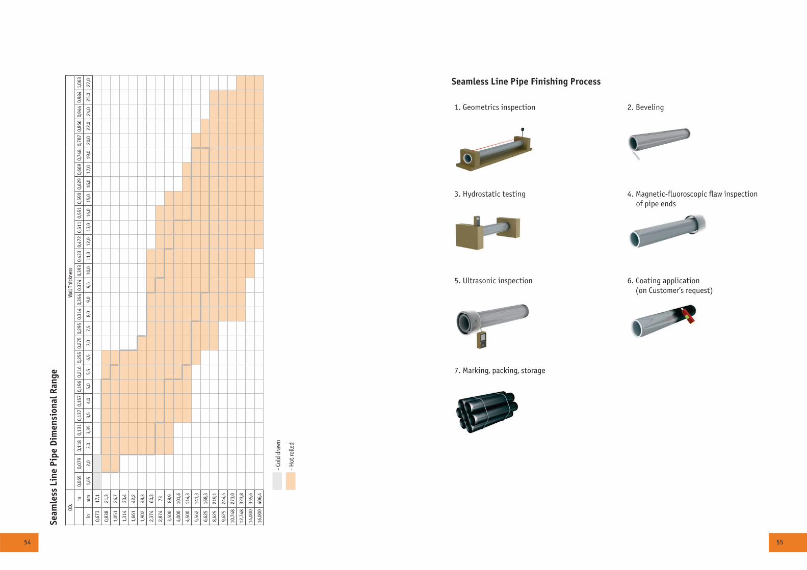
54 55
Seam
less
Lin
e Pi
pe D
imen
sion
al R
ange
OD,
Wal
l Thi
ckne
ss
in0,
065
0,07
90,
118
0,13
10,
137
0,15
70,
196
0,21
60,
255
0,27
50,
295
0,31
40,
354
0,37
40,
393
0,43
30,
472
0,51
10,
551
0,59
00,
629
0,66
90,
748
0,78
70,
866
0,94
40,
984
1,06
3
inm
m1,
652,
03,
03,
353,
54,
05,
05,
5 6,
57,
07,
58,
09,
09,
510
,011
,012
,013
,014
,015
,016
,017
,019
,020
,022
,024
,025
,027
,0
0,67
317
,1
0,83
821
,3
1,05
126
,7
1,31
433
,4
1,66
142
,2
1,90
248
,3
2,37
460
,3
2,87
473
3,50
088
,9
4,00
010
1,6
4,50
011
4,3
5,56
214
1,3
6,62
516
8,3
8,62
521
9,1
9,62
524
4,5
10,7
4827
3,0
12,7
4832
3,8
14,0
0035
5,6
16,0
0040
6,4
- Col
d dr
awn
- Hot
rolle
d
1. Geometrics inspection 2. Beveling
3. Hydrostatic testing 4. Magnetic-fluoroscopic flaw inspection of pipe ends
5. Ultrasonic inspection 6. Coating application (on Customer’s request)
7. Marking, packing, storage
Seamless Line Pipe Finishing Process
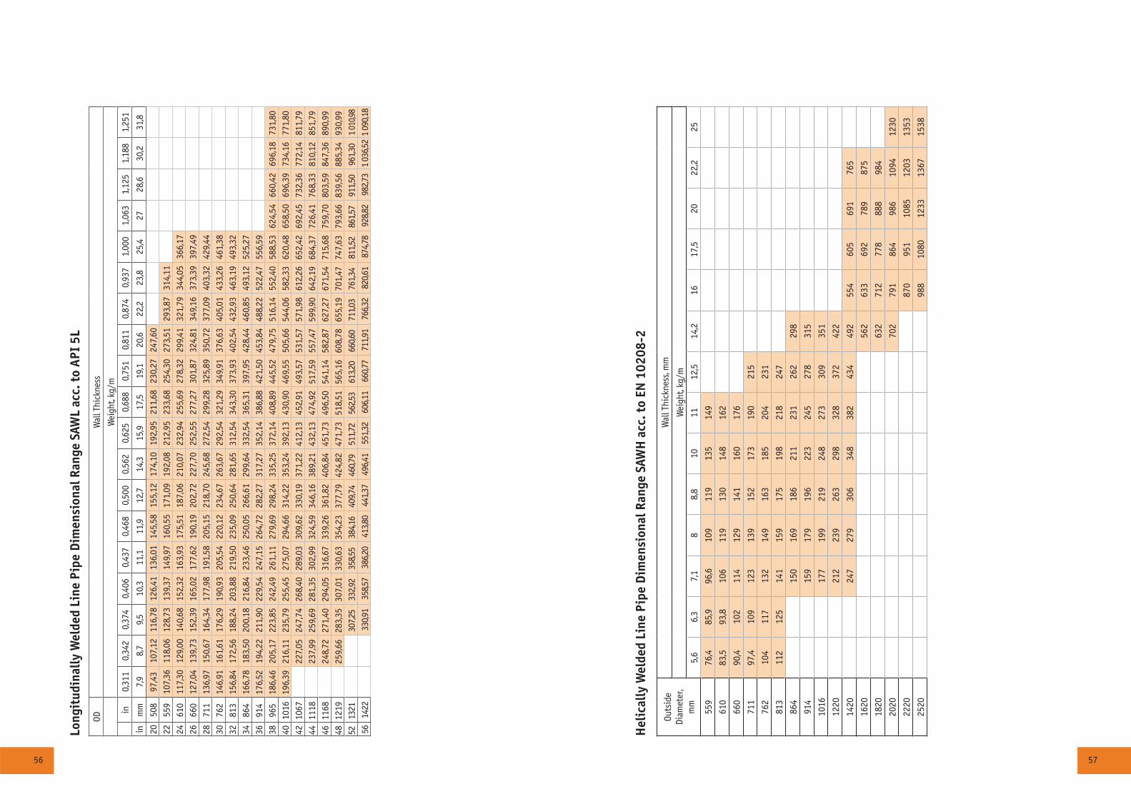
56 57
Long
itud
inal
ly W
elde
d Li
ne P
ipe
Dim
ensi
onal
Ran
ge S
AWL
acc.
to
API
5L
ODW
all T
hick
ness
Wei
ght,
kg/m
in0,
311
0,34
20,
374
0,40
60,
437
0,46
80,
500
0,56
20,
625
0,68
80,
751
0,81
10,
874
0,93
71,
000
1,06
31,
125
1,18
81,
251
inm
m7,
98,
79,
510
,311
,111
,912
,714
,315
,917
,519
,120
,622
,223
,825
,427
28,6
30,2
31,8
2050
897
,43
107,
1211
6,78
126,
4113
6,01
145,
5815
5,12
174,
1019
2,95
211,
6823
0,27
247,
6022
559
107,
3611
8,06
128,
7313
9,37
149,
9716
0,55
171,
0919
2,08
212,
9523
3,68
254,
3027
3,51
293,
8731
4,11
2461
011
7,30
129,
0014
0,68
152,
3216
3,93
175,
5118
7,06
210,
0723
2,94
255,
6927
8,32
299,
4132
1,79
344,
0536
6,17
2666
012
7,04
139,
7315
2,39
165,
0217
7,62
190,
1920
2,72
227,
7025
2,55
277,
2730
1,87
324,
8134
9,16
373,
3939
7,49
2871
113
6,97
150,
6716
4,34
177,
9819
1,58
205,
1521
8,70
245,
6827
2,54
299,
2832
5,89
350,
7237
7,09
403,
3242
9,44
3076
214
6,91
161,
6117
6,29
190,
9320
5,54
220,
1223
4,67
263,
6729
2,54
321,
2934
9,91
376,
6340
5,01
433,
2646
1,38
3281
315
6,84
172,
5618
8,24
203,
8821
9,50
235,
0925
0,64
281,
6531
2,54
343,
3037
3,93
402,
5443
2,93
463,
1949
3,32
3486
416
6,78
183,
5020
0,18
216,
8423
3,46
250,
0526
6,61
299,
6433
2,54
365,
3139
7,95
428,
4446
0,85
493,
1252
5,27
3691
417
6,52
194,
2221
1,90
229,
5424
7,15
264,
7228
2,27
317,
2735
2,14
386,
8842
1,50
453,
8448
8,22
522,
4755
6,59
3896
518
6,46
205,
1722
3,85
242,
4926
1,11
279,
6929
8,24
335,
2537
2,14
408,
8944
5,52
479,
7551
6,14
552,
4058
8,53
624,
5466
0,42
696,
1873
1,80
4010
1619
6,39
216,
1123
5,79
255,
4527
5,07
294,
6631
4,22
353,
2439
2,13
430,
9046
9,55
505,
6654
4,06
582,
3362
0,48
658,
5069
6,39
734,
1677
1,80
4210
6722
7,05
247,
7426
8,40
289,
0330
9,62
330,
1937
1,22
412,
1345
2,91
493,
5753
1,57
571,
9861
2,26
652,
4269
2,45
732,
3677
2,14
811,
7944
1118
237,
9925
9,69
281,
3530
2,99
324,
5934
6,16
389,
2143
2,13
474,
9251
7,59
557,
4759
9,90
642,
1968
4,37
726,
4176
8,33
810,
1285
1,79
4611
6824
8,72
271,
4029
4,05
316,
6733
9,26
361,
8240
6,84
451,
7349
6,50
541,
1458
2,87
627,
2767
1,54
715,
6875
9,70
803,
5984
7,36
890,
9948
1219
259,
6628
3,35
307,
0133
0,63
354,
2337
7,79
424,
8247
1,73
518,
5156
5,16
608,
7865
5,19
701,
4774
7,63
793,
6683
9,56
885,
3493
0,99
5213
2130
7,25
332,9
235
8,55
384,1
640
9,74
460,7
951
1,72
562,5
361
3,20
660,6
071
1,03
761,3
481
1,52
861,5
791
1,50
961,3
01
010,9
856
1422
330,9
135
8,57
386,2
041
3,80
441,3
749
6,41
551,3
260
6,11
660,7
771
1,91
766,3
282
0,61
874,7
892
8,82
982,7
31
036,5
21
090,1
8
Hel
ical
ly W
elde
d Li
ne P
ipe
Dim
ensi
onal
Ran
ge S
AWH
acc
. to
EN 1
0208
-2
Outs
ide
Diam
eter
,m
m
Wal
l Thi
ckne
ss, m
m
Wei
ght,
kg/m
5,6
6,3
7,1
88,
810
1112
,514
,216
17,5
2022
,225
559
76,4
85,9
96,6
109
119
135
149
610
83,5
93,8
106
119
130
148
162
660
90,4
102
114
129
141
160
176
711
97,4
109
123
139
152
173
190
215
762
104
117
132
149
163
185
204
231
813
112
125
141
159
175
198
218
247
864
150
169
186
211
231
262
298
914
159
179
196
223
245
278
315
1016
177
199
219
248
273
309
351
1220
212
239
263
298
328
372
422
1420
247
279
306
348
382
434
492
554
605
691
765
1620
562
633
692
789
875
1820
632
712
778
888
984
2020
702
791
864
986
1094
1230
2220
870
951
1085
1203
1353
2520
988
1080
1233
1367
1538

58 59
1. Infeed of plates Identity check 2. Milling of longitudinal plate edges
5. Tack welding 6. Inside welding
9. UT of weld 10. X-ray testing of weld seam
13. Hydrostatic testing 14. UT of weld seam
17. Inspection, weighing, marking, stamping 18. Storage
Longitudinal Process Flowchart 20” - 56” /508 - 1422 mm/
3. Forming by the 3-roll bending process 4. Post-bending of the longitudinal plate edges
7. Outside welding 8. Visual control
11. Mechanical expanding 12. Grinding of weld at pipe ends and beveling
15. X-ray testing of weld seam and pipe ends 16. Magnetic particle and ultrasonic inspection of both pipe ends
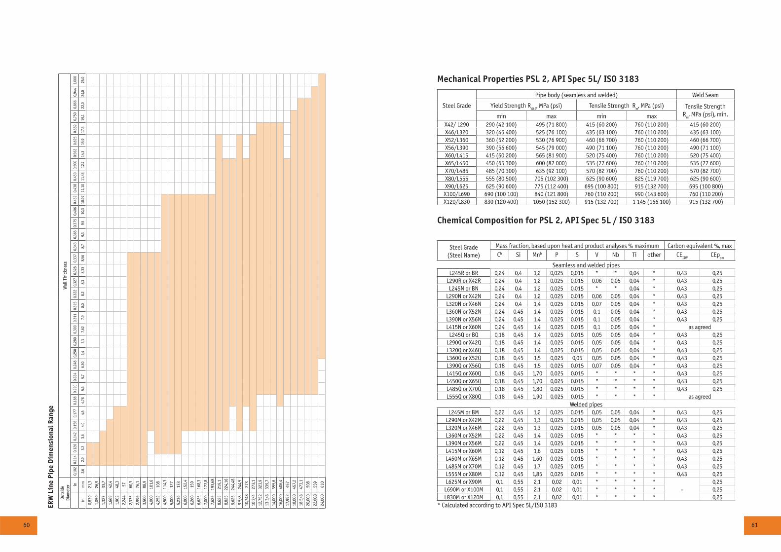
60 61
ERW
Lin
e Pi
pe D
imen
sion
al R
ange
Outs
ide
Diam
eter
Wal
l Thi
ckne
ss
in0,
102
0,11
40,
126
0,14
20,
156
0,17
70,
188
0,22
00,
224
0,24
80,
250
0,28
00,
300
0,31
10,
315
0,32
20,
327
0,32
80,
337
0,34
30,
365
0,37
50,
406
0,43
20,
438
0,45
00,
500
0,56
20,
625
0,68
90,
750
0,86
60,
944
1,00
0
inm
m2,
62,
93,
23,
64,
04,
54,
785,
65,
76,
306,
47,
17,
627,
98,
08,
28,
38,
338,
568,
79,
39,
510
,310
,97
11,1
011
,43
12,7
14,3
15,9
17,5
19,1
22,0
24,0
25,0
0,83
921
,3
1,05
926
,9
1,32
733
,7
1,66
942
,4
1,90
248
,3
2,24
457
2,37
560
,3
2,99
676
,1
3,50
088
,9
4,00
010
1,6
4,25
210
8
4,50
011
4,3
5,00
012
7
5,23
613
3
6,00
015
2,4
6,26
015
9
6,62
516
8,3
7,00
017
7,8
7,62
519
3,68
8,62
521
9,1
8,82
522
4,16
9,62
524
4,48
9 5/
824
4,5
10,7
4827
3
10 3
/427
3,1
12,7
5232
3,9
13 3
/833
9,7
14,0
0035
5,6
16,0
0040
6,4
17,9
9245
7
18,0
0045
7,2
18 5
/847
3,1
20,0
0050
8
22,0
0055
9
24,0
0061
0
Mechanical Properties PSL 2, API Spec 5L/ ISO 3183
Steel Grade
Pipe body (seamless and welded) Weld Seam
Yield Strength Rt0,5
, MPa (psi) Tensile Strength Rm, MPa (psi) Tensile Strength
Rm, MPa (psi), min.min max min max
Õ42/ L290 290 (42 100) 495 (71 800) 415 (60 200) 760 (110 200) 415 (60 200)X46/L320 320 (46 400) 525 (76 100) 435 (63 100) 760 (110 200) 435 (63 100)X52/L360 360 (52 200) 530 (76 900) 460 (66 700) 760 (110 200) 460 (66 700)X56/L390 390 (56 600) 545 (79 000) 490 (71 100) 760 (110 200) 490 (71 100)X60/L415 415 (60 200) 565 (81 900) 520 (75 400) 760 (110 200) 520 (75 400)X65/L450 450 (65 300) 600 (87 000) 535 (77 600) 760 (110 200) 535 (77 600)X70/L485 485 (70 300) 635 (92 100) 570 (82 700) 760 (110 200) 570 (82 700)X80/L555 555 (80 500) 705 (102 300) 625 (90 600) 825 (119 700) 625 (90 600)Õ90/L625 625 (90 600) 775 (112 400) 695 (100 800) 915 (132 700) 695 (100 800)
Õ100/L690 690 (100 100) 840 (121 800) 760 (110 200) 990 (143 600) 760 (110 200)Õ120/L830 830 (120 400) 1050 (152 300) 915 (132 700) 1 145 (166 100) 915 (132 700)
Chemical Composition for PSL 2, API Spec 5L / ISO 3183
Steel Grade(Steel Name)
Mass fraction, based upon heat and product analyses % maximum Carbon equivalent %, maxÑb Si Mnb P S V Nb Ti other CE
IIWCEp
cm
Seamless and welded pipesL245R or BR 0,24 0,4 1,2 0,025 0,015 * * 0,04 * 0,43 0,25
L290R or X42R 0,24 0,4 1,2 0,025 0,015 0,06 0,05 0,04 * 0,43 0,25L245N or BN 0,24 0,4 1,2 0,025 0,015 * * 0,04 * 0,43 0,25
L290N or X42N 0,24 0,4 1,2 0,025 0,015 0,06 0,05 0,04 * 0,43 0,25L320N or X46N 0,24 0,4 1,4 0,025 0,015 0,07 0,05 0,04 * 0,43 0,25L360N or X52N 0,24 0,45 1,4 0,025 0,015 0,1 0,05 0,04 * 0,43 0,25L390N or X56N 0,24 0,45 1,4 0,025 0,015 0,1 0,05 0,04 * 0,43 0,25L415N or Õ60N 0,24 0,45 1,4 0,025 0,015 0,1 0,05 0,04 * as agreed
L245Q or BQ 0,18 0,45 1,4 0,025 0,015 0,05 0,05 0,04 * 0,43 0,25L290Q or X42Q 0,18 0,45 1,4 0,025 0,015 0,05 0,05 0,04 * 0,43 0,25L320Q or X46Q 0,18 0,45 1,4 0,025 0,015 0,05 0,05 0,04 * 0,43 0,25L360Q or X52Q 0,18 0,45 1,5 0,025 0,05 0,05 0,05 0,04 * 0,43 0,25L390Q or X56Q 0,18 0,45 1,5 0,025 0,015 0,07 0,05 0,04 * 0,43 0,25L415Q or Õ60Q 0,18 0,45 1,70 0,025 0,015 * * * * 0,43 0,25L450Q or X65Q 0,18 0,45 1,70 0,025 0,015 * * * * 0,43 0,25L485Q or X70Q 0,18 0,45 1,80 0,025 0,015 * * * * 0,43 0,25L555Q or X80Q 0,18 0,45 1,90 0,025 0,015 * * * * as agreed
Welded pipesL245M or ÂÌ 0,22 0,45 1,2 0,025 0,015 0,05 0,05 0,04 * 0,43 0,25
L290M or Õ42Ì 0,22 0,45 1,3 0,025 0,015 0,05 0,05 0,04 * 0,43 0,25L320M or Õ46Ì 0,22 0,45 1,3 0,025 0,015 0,05 0,05 0,04 * 0,43 0,25L360M or Õ52Ì 0,22 0,45 1,4 0,025 0,015 * * * * 0,43 0,25L390M or Õ56Ì 0,22 0,45 1,4 0,025 0,015 * * * * 0,43 0,25L415Ì or Õ60Ì 0,12 0,45 1,6 0,025 0,015 * * * * 0,43 0,25L450M or Õ65Ì 0,12 0,45 1,60 0,025 0,015 * * * * 0,43 0,25L485M or Õ70Ì 0,12 0,45 1,7 0,025 0,015 * * * * 0,43 0,25L555M or Õ80Ì 0,12 0,45 1,85 0,025 0,015 * * * * 0,43 0,25L625M or Õ90Ì 0,1 0,55 2,1 0,02 0,01 * * * *
-0,25
L690M or Õ100Ì 0,1 0,55 2,1 0,02 0,01 * * * * 0,25L830Ì or Õ120Ì 0,1 0,55 2,1 0,02 0,01 * * * * 0,25
* Calculated according to API Spec 5L/ISO 3183
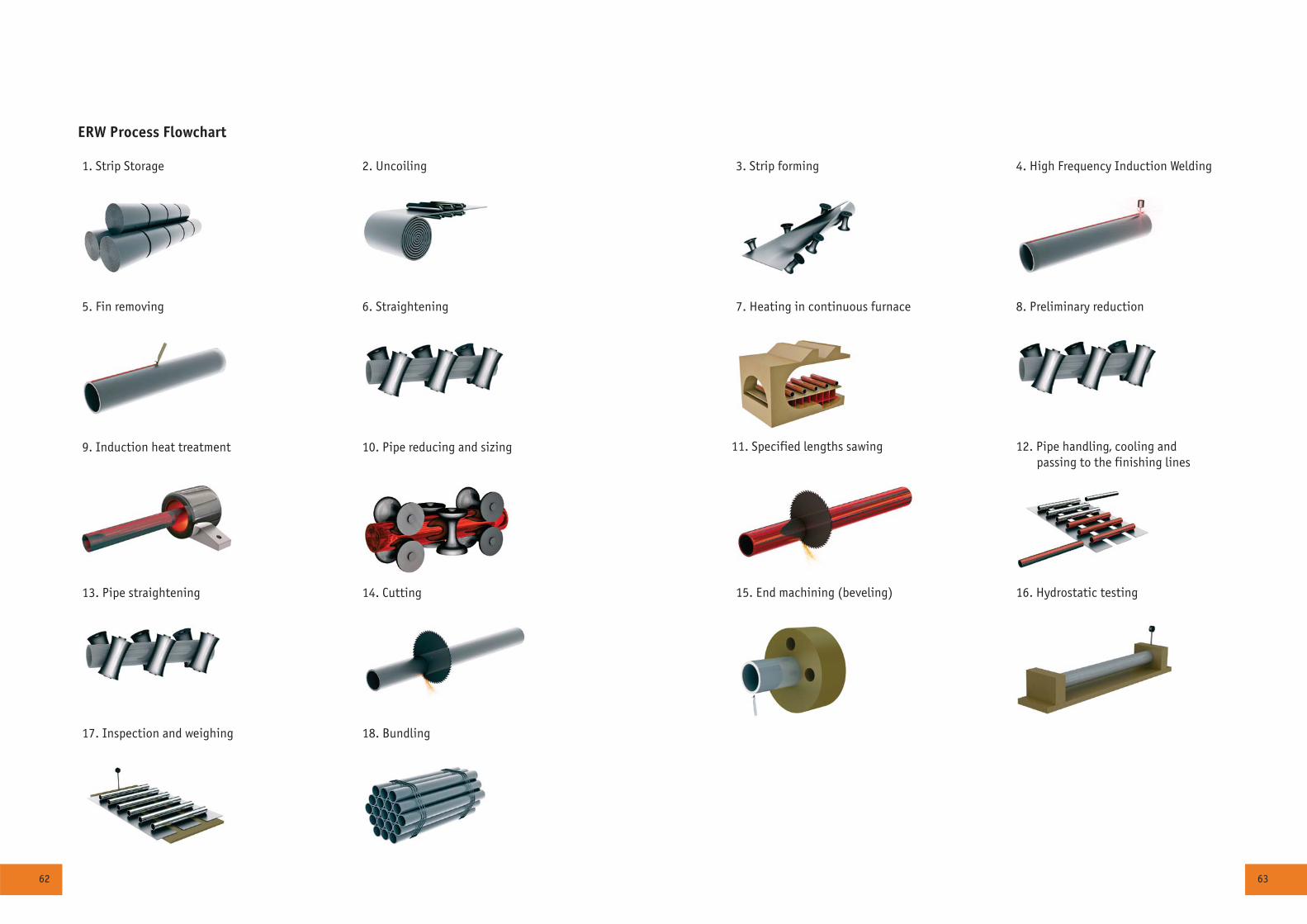
62 63
1. Strip Storage 2. Uncoiling
5. Fin removing 6. Straightening
9. Induction heat treatment 10. Pipe reducing and sizing
13. Pipe straightening 14. Cutting
17. Inspection and weighing 18. Bundling
ERW Process Flowchart
3. Strip forming 4. High Frequency Induction Welding
7. Heating in continuous furnace 8. Preliminary reduction
11. Specified lengths sawing 12. Pipe handling, cooling and passing to the finishing lines
15. End machining (beveling) 16. Hydrostatic testing
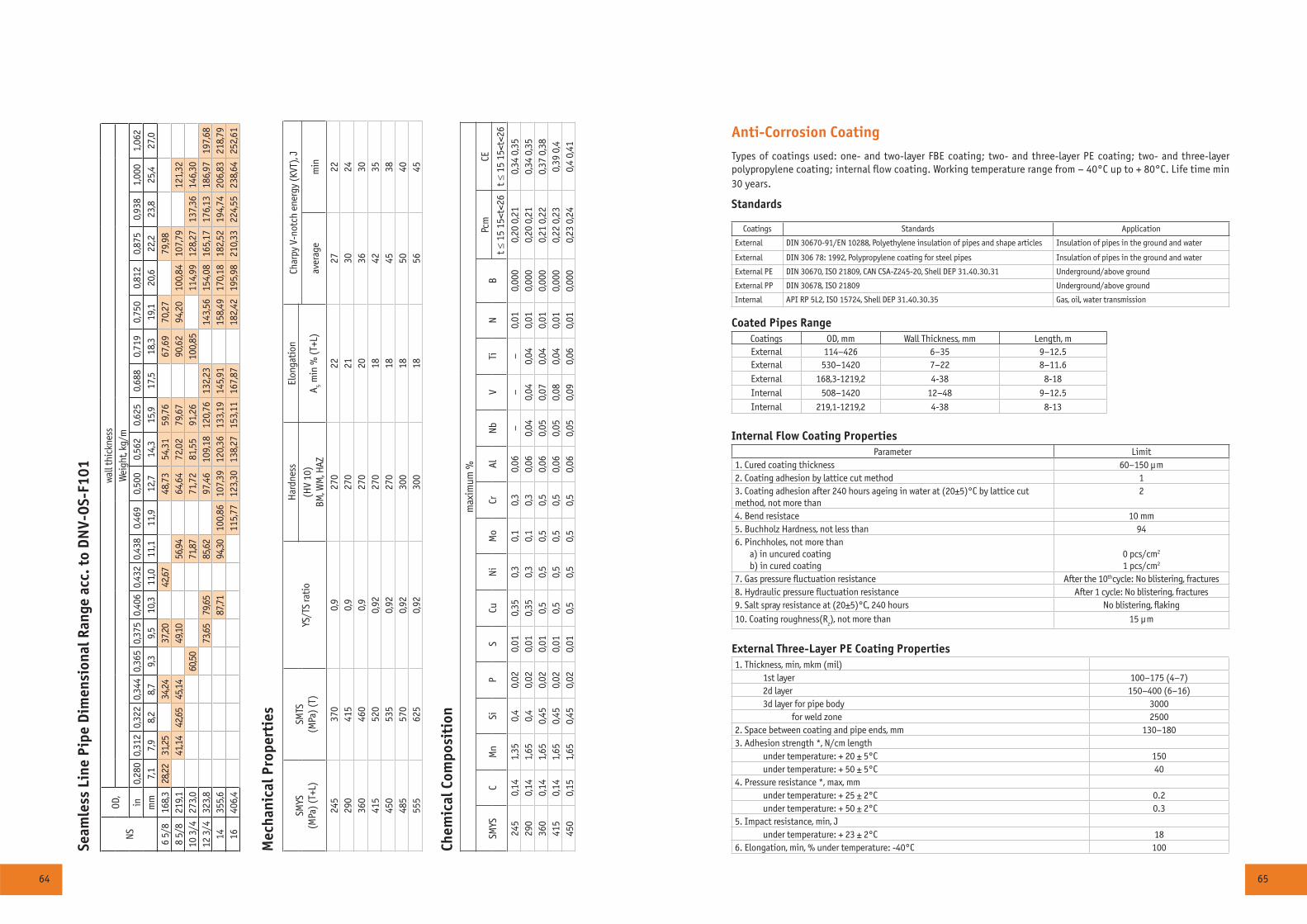
64 65
Chem
ical
Com
posi
tion
max
imum
%
SMYS
C M
nSi
PS
CuN
iM
oCr
Al
Nb
V Ti
N
BPc
mCE
t ≤ 1
5 15
<t<2
6t ≤
15
15<t
<26
245
0,14
1,35
0,4
0,02
0,01
0,35
0,3
0,1
0,3
0,06
––
–0,
010,
000
0,20
0,2
10,
34 0
,35
290
0,14
1,65
0,4
0,02
0,01
0,35
0,3
0,1
0,3
0,06
0,04
0,04
0,04
0,01
0,00
00,
20 0
,21
0,34
0,3
536
00,
141,
650,
450,
020,
010,
50,
50,
50,
50,
060,
050,
070,
040,
010,
000
0,21
0,2
20,
37 0
,38
415
0,14
1,65
0,45
0,02
0,01
0,5
0,5
0,5
0,5
0,06
0,05
0,08
0,04
0,01
0,00
00,
22 0
,23
0,39
0,4
450
0,15
1,65
0,45
0,02
0,01
0,5
0,5
0,5
0,5
0,06
0,05
0,09
0,06
0,01
0,00
00,
23 0
,24
0,4
0,41
Mec
hani
cal P
rope
rtie
s
SMYS
(MPa
) (T+
L)SM
TS(M
Pa) (
T)YS
/TS
rati
oH
ardn
ess
Elon
gati
onCh
arpy
V-n
otch
ene
rgy
(KVT
), J
(HV
10)
BM, W
M, H
AZÀ 5 m
in %
(T+L
)av
erag
em
in
245
370
0,9
270
2227
2229
041
50,
927
021
3024
360
460
0,9
270
2036
3041
552
00,
9227
018
4235
450
535
0,92
270
1845
3848
557
00,
9230
018
5040
555
625
0,92
300
1856
45
Anti-Corrosion Coating
Types of coatings used: one- and two-layer FBE coating; two- and three-layer PE coating; two- and three-layer polypropylene coating; internal flow coating. Working temperature range from – 40°Ñ up to + 80°Ñ. Life time min 30 years.
Standards
Coatings Standards Application
External DIN 30670-91/EN 10288, Polyethylene insulation of pipes and shape articles Insulation of pipes in the ground and water
External DIN 306 78: 1992, Polypropylene coating for steel pipes Insulation of pipes in the ground and water
External PE DIN 30670, ISO 21809, CAN CSA-Z245-20, Shell DEP 31.40.30.31 Underground/above ground
External PP DIN 30678, ISO 21809 Underground/above ground
Internal API RP 5L2, ISO 15724, Shell DEP 31.40.30.35 Gas, oil, water transmission
Coated Pipes RangeCoatings OD, mm Wall Thickness, mm Length, m External 114–426 6–35 9–12.5External 530–1420 7–22 8–11.6
External 168,3-1219,2 4-38 8-18
Internal 508–1420 12–48 9–12.5
Internal 219,1-1219,2 4-38 8-13
Internal Flow Coating PropertiesParameter Limit
1. Cured coating thickness 60–150 μm2. Coating adhesion by lattice cut method 13. Coating adhesion after 240 hours ageing in water at (20±5)°C by lattice cut method, not more than
2
4. Bend resistace 10 mm5. Buchholz Hardness, not less than 946. Pinchholes, not more than a) in uncured coating b) in cured coating
0 pcs/cm2
1 pcs/cm2
7. Gas pressure fluctuation resistance After the 10thcycle: No blistering, fractures8. Hydraulic pressure fluctuation resistance After 1 cycle: No blistering, fractures9. Salt spray resistance at (20±5)°C, 240 hours No blistering, flaking
10. Coating roughness(Rz), not more than 15 μm
External Three-Layer PE Coating Properties1. Thickness, min, mkm (mil)
1st layer 100–175 (4–7)2d layer 150–400 (6–16)3d layer for pipe body 3000
for weld zone 25002. Space between coating and pipe ends, mm 130–1803. Adhesion strength *, N/cm length
under temperature: + 20 ± 5°Ñ 150under temperature: + 50 ± 5°Ñ 40
4. Pressure resistance *, max, mmunder temperature: + 25 ± 2°Ñ 0.2under temperature: + 50 ± 2°Ñ 0.3
5. Impact resistance, min, Junder temperature: + 23 ± 2°Ñ 18
6. Elongation, min, % under temperature: -40°Ñ 100Seam
less
Lin
e Pi
pe D
imen
sion
al R
ange
acc
. to
DN
V-O
S-F1
01
NSOD
, w
all t
hick
ness
Wei
ght,
kg/m
in0,
280
0,31
20,
322
0,34
40,
365
0,37
50,
406
0,43
20,
438
0,46
90,
500
0,56
20,
625
0,68
80,
719
0,75
00,
812
0,87
50,
938
1,00
01,
062
mm
7,1
7,9
8,2
8,7
9,3
9,5
10,3
11,0
11,1
11,9
12,7
14,3
15,9
17,5
18,3
19,1
20,6
22,2
23,8
25,4
27,0
6 5/
8 16
8,3
28,22
31,25
34,24
37,20
42,67
48,7
354
,31
59,7
667
,69
70,2
779
,98
8 5/
8 21
9,1
41,14
42,65
45,14
49,10
56,94
64,6
472
,02
79,6
790
,62
94,2
010
0,84
107,
7912
1,32
10 3
/4
273,
060
,5071
,87
71,7
281
,55
91,2
610
0,85
114,
9912
8,27
137,
3614
6,30
12 3
/4
323,
873
,6579
,6585
,6297
,46
109,
1812
0,76
132,
2314
3,56
154,
0816
5,17
176,
1318
6,97
197,
6814
355,
687
,7194
,3010
0,86
107,
3912
0,36
133,
1914
5,91
158,
4917
0,18
182,
5219
4,74
206,
8321
8,79
1640
6,4
115,
7712
3,30
138,
2715
3,11
167,
8718
2,42
195,
9821
0,33
224,
5523
8,64
252,
61
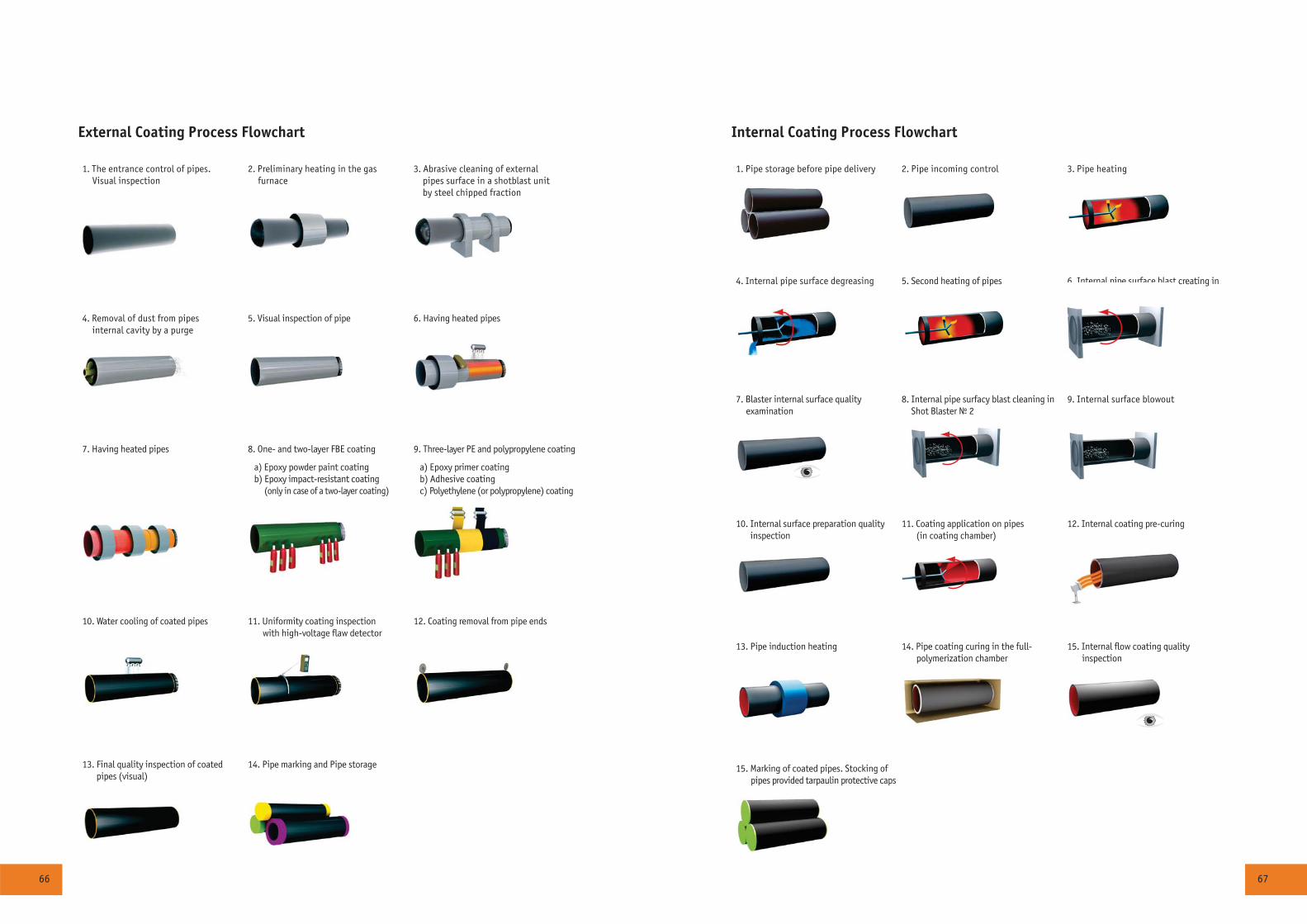
66 67
1. Pipe storage before pipe delivery 2. Pipe incoming control 3. Pipe heating
4. Internal pipe surface degreasing 5. Second heating of pipes 6. Internal pipe surface blast creating in Shot Blaster ¹ 1
7. Blaster internal surface quality examination
8. Internal pipe surfacó blast cleaning in Shot Blaster ¹ 2
9. Internal surface blowout
10. Internal surface preparation quality inspection
11. Coating application on pipes (in coating chamber)
12. Internal coating pre-curing
13. Pipe induction heating 14. Pipe coating curing in the full- polymerization chamber
15. Internal flow coating quality inspection
15. Marking of coated pipes. Stocking of pipes provided tarpaulin protective caps
Internal Coating Process Flowchart
1. The entrance control of pipes. Visual inspection
2. Preliminary heating in the gas furnace
3. Abrasive cleaning of external pipes surface in a shotblast unit by steel chipped fraction
4. Removal of dust from pipes internal cavity by a purge
5. Visual inspection of pipe 6. Having heated pipes
7. Having heated pipes 8. One- and two-layer FBE coating
a) Epoxy powder paint coatingb) Epoxy impact-resistant coating (only in case of a two-layer coating)
9. Three-layer PE and polypropylene coating
à) Epoxy primer coatingb) Adhesive coatingc) Polyethylene (or polypropylene) coating
10. Water cooling of coated pipes 11. Uniformity coating inspection with high-voltage flaw detector
12. Coating removal from pipe ends
13. Final quality inspection of coated pipes (visual)
14. Pipe marking and Pipe storage
External Coating Process Flowchart
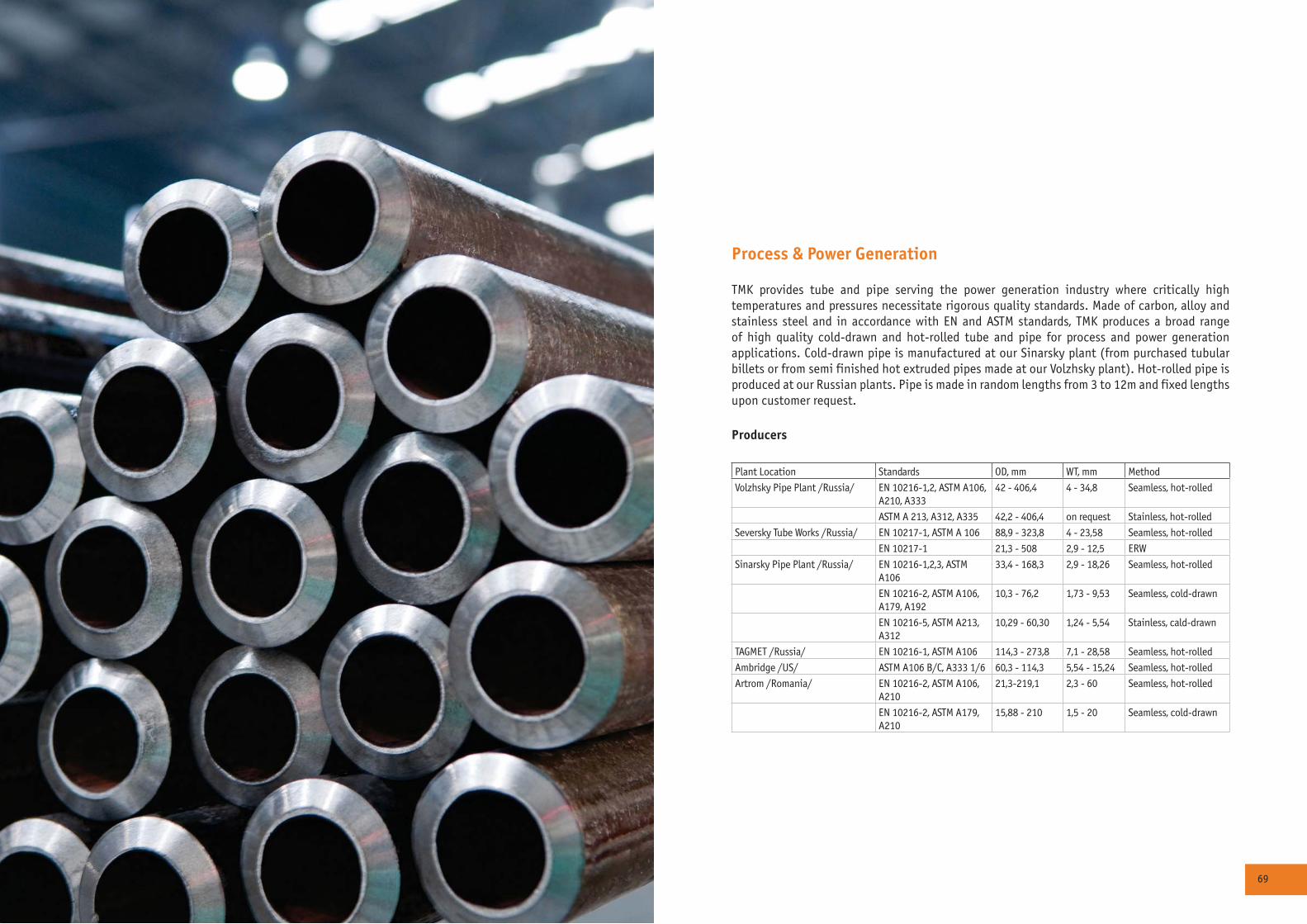
68 69
Process & Power Generation
TMK provides tube and pipe serving the power generation industry where critically high temperatures and pressures necessitate rigorous quality standards. Made of carbon, alloy and stainless steel and in accordance with EN and ASTM standards, TMK produces a broad range of high quality cold-drawn and hot-rolled tube and pipe for process and power generation applications. Cold-drawn pipe is manufactured at our Sinarsky plant (from purchased tubular billets or from semi finished hot extruded pipes made at our Volzhsky plant). Hot-rolled pipe is produced at our Russian plants. Pipe is made in random lengths from 3 to 12m and fixed lengths upon customer request.
Producers
Plant Location Standards OD, mm WT, mm Method
Volzhsky Pipe Plant /Russia/ EN 10216-1,2, ASTM A106, A210, A333
42 - 406,4 4 - 34,8 Seamless, hot-rolled
ASTM A 213, A312, A335 42,2 - 406,4 on request Stainless, hot-rolled
Seversky Tube Works /Russia/ EN 10217-1, ASTM A 106 88,9 - 323,8 4 - 23,58 Seamless, hot-rolled
EN 10217-1 21,3 - 508 2,9 - 12,5 ERW
Sinarsky Pipe Plant /Russia/ EN 10216-1,2,3, ASTM A106
33,4 - 168,3 2,9 - 18,26 Seamless, hot-rolled
EN 10216-2, ASTM A106, A179, A192
10,3 - 76,2 1,73 - 9,53 Seamless, cold-drawn
EN 10216-5, ASTM A213, A312
10,29 - 60,30 1,24 - 5,54 Stainless, cald-drawn
TAGMET /Russia/ EN 10216-1, ASTM A106 114,3 - 273,8 7,1 - 28,58 Seamless, hot-rolled
Ambridge /US/ ASTM A106 B/C, A333 1/6 60,3 - 114,3 5,54 - 15,24 Seamless, hot-rolled
Artrom /Romania/ EN 10216-2, ASTM A106, A210
21,3-219,1 2,3 - 60 Seamless, hot-rolled
EN 10216-2, ASTM A179, A210
15,88 - 210 1,5 - 20 Seamless, cold-drawn
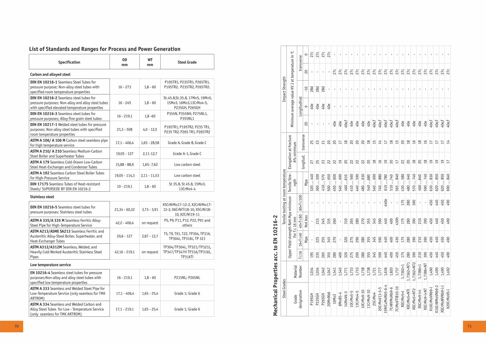
70 71
Mec
hani
cal P
rope
rtie
s ac
c. t
o EN
102
16-2
Stee
l Gra
des
Tens
ile te
stin
g at
room
tem
pera
ture
Impa
ct S
tren
gth
Grad
ede
sign
atio
nM
ater
ial
Num
ber
Upp
er Y
ield
str
engt
h Re
H M
pa m
inim
um
For T≤
16 m
mTe
nsile
Str
e-ng
thEl
onga
tion
at f
ract
ure
A% m
inim
umM
inim
um a
vera
ge v
alue
KV
J at
tem
pera
ture
in o C
Ò≤16
16<Ò≤4
040
<Ò≤6
060
<Ò≤1
00lo
ngit
ud.
tran
sver
seLo
ngit
udin
altr
ansv
erse
Mpa
Not
less
Mpa
200
-10
200
P195
GH1,
034
195
--
-32
0 ..
. 440
2725
-40
å28
d-
27c
P235
GH1,
034
235
225
215
-36
0 ..
. 500
2523
-40
å28
d-
27c
P265
GH1,
042
265
255
245
-41
0...
570
2321
-40
å28
d-
27c
20M
nNb6
1,04
735
534
533
5-
500
... 6
5022
20-
40å
--
27c
16Ì
îÇ1,
541
280
270
260
-45
0 ..
. 600
2220
40å
--
27c
-8Ì
îÂ5-
41,
545
400
--
-54
0 ..
. 690
1917
40å
--
27c
-14
MoV
6-3
1,77
132
032
031
0-
460
...6
1020
1840
å,f
--
27c
-10
ÑrÌ
î5-5
1,73
327
527
526
5-
410
... 5
6022
2040
å-
-27
c-
13Ñr
Ìî4
-51,
733
290
290
280
-44
0 ..
. 590
2220
40å
--
27c
-10
ÑrÌ
î9-1
01,
738
280
280
270
-48
0 ..
. 630
2220
40å
--
27c
-11
ÑrÌ
î9-1
01,
738
355
355
355
-54
0 ..
.680
2018
40å
--
27c
-25
ÑrÌ
î41,
721
345
34S
345
-54
0 ..
. 690
1815
40å,
f-
-27
c-
20Cr
MoV
13-5
-51,
777
590
590
590
-74
0 ..
. 880
1614
40å,
f-
-27
c-
15N
iCuM
oNb5
-6-4
1,63
644
044
044
044
0å61
0 ..
.780
1917
40å,
f-
-27
c-
7CrW
VMoN
b9-6
1,82
040
040
040
0-
510
...7
4020
1840
å,f
--
27c
-7C
rMoV
TiB1
0-10
1,73
745
043
043
0h-
565
... 8
4017
1540
å,f
--
27c
-Xl
lCrM
o5+l
1.73
62+1
175
175
175
175
430
... 5
8022
2040
å-
-27
c-
XllC
rMo5
+NTl
1.73
62+N
T128
028
028
028
048
0 ..
. 640
2018
40å
--
27c
-Xl
lCrM
o5+N
T21.
7362
+NT2
390
390
390
390
570
... 7
4018
1640
å-
-27
c-
XllC
rMo9
-l+l
1.73
86+1
210
210
210
-46
0 ..
.640
2018
40å
--
27c
-Xl
lCrM
o9-l
+NT
1.73
86+N
T39
039
039
0-
590
... 7
4018
1640
å-
-27
c-
X10C
rMoV
Nb9
-l1,
490
450
450
450
450
630
... 8
3019
1740
å,f
--
27c
-X1
0CrW
MoV
Nb9
-21,
490
440
440
440
440
620
... 8
5019
1740
å,f
--
27c
-Xl
lCrM
oWVN
b9-l
-l1,
490
450
450
450
450
620
... 8
5019
1740
å,f
--
27c
-X2
0CrM
oVll-
l1,
492
490
490
490
490
690
... 8
4017
1440
å,f
--
27c
-
List of Standards and Ranges for Process and Power Generation
SpecificationODmm
WTmm
Steel Grade
Carbon and alloyed steel
DIN EN 10216-1 Seamless Steel Tubes for pressure purpose; Non-alloy steel tubes with specified room temperature properties
16 - 273 1,8 - 60P195TR1, P235TR1, P265TR1, P195TR2, P235TR2, P265TR2.
DIN EN 10216-2 Seamless steel tubes for pressure purposes; Non-alloy and alloy steel tubes with specified elevated temperature properties
16 - 245 1,8 - 60 St.45.8,St.35.8, 17Mn5, 19Mn5,
15Mo3, 16Mo3,13CrMo4-5, P235GH, P265GH
DIN EN 10216-3 Seamless steel tubes for pressure purposes; Alloy fine grain steel tubes
16 - 219,1 1,8 -60P355N, P355NH, P275NL1,
P355NL1
DIN EN 10217-1 Welded steel tubes for pressure purposes; Non-alloy steel tubes with specified room temperature properties
21,3 - 508 4,0 - 12,5P195TR1, P195TR2, P235 TR1, P235 TR2, P265 TR1, P265TR2
ASTM A 106/ A 106 Ì Carbon steel seamless pipe for high temperature service
17,1 - 406,4 1,65 - 28,58 Grade A, Grade B, Grade C
ASTM A 210/ A 210 Seamless Medium-Carbon Steel Boiler and Superheater Tubes
19,05 - 127 2,11-12,7 Grade A-1, Grade Ñ
ASTM A 179 Seamless Cold-Drawn Low-Carbon Steel Heat-Exchanger and Condenser Tubes
15,88 - 88,9 1,65- 7,62 Low carbon steel
ASTM A 192 Seamless Carbon Steel Boiler Tubes for High-Pressure Service
19,05 - 114,3 2,11 - 11,53 Low carbon steel
DIN 17175 Seamless Tubes of Heat-resistant Steels/ SUPERSEDE BY DIN EN 10216-2
10 - 219,1 1,8 - 60St 35.8, St 45.8, 15Mo3,
13CrMo4-4
Stainless steel
DIN EN 10216-5 Seamless steel tubes for pressure purposes; Stainless steel tubes
21,34 - 60,32 3,73 - 3,91X5CrNiMo17-12-2, X2CrNiMo17-12-2, X6CrNiTi18-10, X5CrNi18-
10, X2CrNi19-11
ASTM A 335/A 335 M Seamless Ferritic Alloy-Steel Pipe for High-Temperature Service
42,2 - 406,4 on requestP5, P9, P11, P12, P22, P91 and
others
ASTM A213/ASME SA213 Seamless Ferritic and Austenitic Alloy-Steel Boiler, Superheater, and Heat-Exchanger Tubes
20,6 - 127 2,87 - 12,7T5, T9, T91, T22, TP304, TP316,
TP304L, TP316L, TP 321
ASTM À312/À312Ì Seamless, Welded, and Heavily Cold Worked Austenitic Stainless Steel Pipes
42,16 - 219,1 on requestTP304/ÒÐ304L, TP321/ÒÐ321L, ÒÐ347/ÒÐ347Í TP316/ÒÐ316L,
ÒÐ316Ti
Low temperature service
EN 10216-4 Seamless steel tubes for pressure purposes;Non-alloy and alloy steel tubes with specified low temperature properties
16 - 219,1 1,8 - 60 P215NL; P265NL
ASTM A 333 Seamless and Welded Steel Pipe for Low-Temperature Service (only seamless for TMK ARTROM)
17,1 - 406,4 1,65 - 25,4 Grade 1; Grade 6
ASTM A 334 Seamless and Welded Carbon and Alloy Steel Tubes for Low - Temperature Service (only seamless for TMK ARTROM)
17,1 - 219,1 1,65 - 25,4 Grade 1; Grade 6
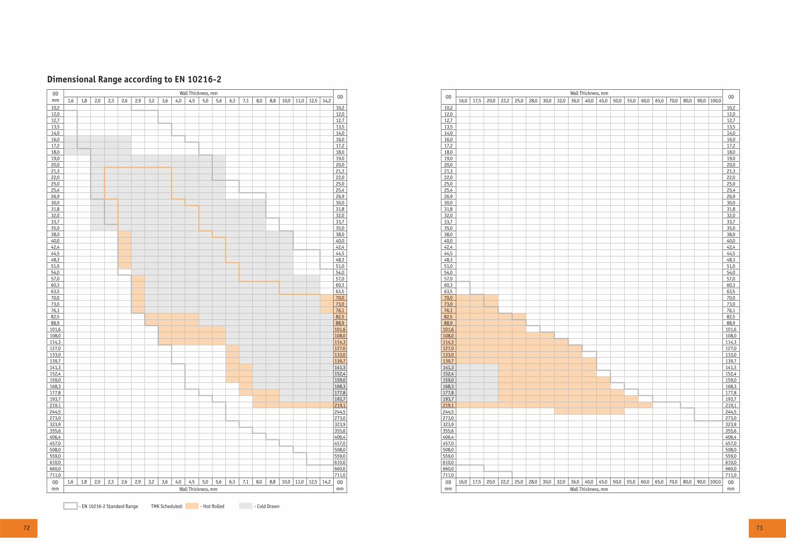
72 73
Dimensional Range according to EN 10216-2ODmm
Wall Thickness, mmOD OD
Wall Thickness, mmOD
1,6 1,8 2,0 2,3 2,6 2,9 3,2 3,6 4,0 4,5 5,0 5,6 6,3 7,1 8,0 8,8 10,0 11,0 12,5 14,2 16,0 17,5 20,0 22,2 25,0 28,0 30,0 32,0 36,0 40,0 45,0 50,0 55,0 60,0 65,0 70,0 80,0 90,0 100,010,2 10,2 10,2 10,212,0 12,0 12,0 12,012,7 12,7 12,7 12,713,5 13,5 13,5 13,514,0 14,0 14,0 14,016,0 16,0 16,0 16,017,2 17,2 17,2 17,218,0 18,0 18,0 18,019,0 19,0 19,0 19,020,0 20,0 20,0 20,021,3 21,3 21,3 21,322,0 22,0 22,0 22,025,0 25,0 25,0 25,025,4 25,4 25,4 25,426,9 26,9 26,9 26,930,0 30,0 30,0 30,031,8 31,8 31,8 31,832,0 32,0 32,0 32,033,7 33,7 33,7 33,735,0 35,0 35,0 35,038,0 38,0 38,0 38,040,0 40,0 40,0 40,042,4 42,4 42,4 42,444,5 44,5 44,5 44,548,3 48,3 48,3 48,351,0 51,0 51,0 51,054,0 54,0 54,0 54,057,0 57,0 57,0 57,060,3 60,3 60,3 60,363,5 63,5 63,5 63,570,0 70,0 70,0 70,073,0 73,0 73,0 73,076,1 76,1 76,1 76,182,5 82,5 82,5 82,588,9 88,9 88,9 88,9
101,6 101,6 101,6 101,6108,0 108,0 108,0 108,0114,3 114,3 114,3 114,3127,0 127,0 127,0 127,0133,0 133,0 133,0 133,0139,7 139,7 139,7 139,7141,3 141,3 141,3 141,3152,4 152,4 152,4 152,4159,0 159,0 159,0 159,0168,3 168,3 168,3 168,3177,8 177,8 177,8 177,8193,7 193,7 193,7 193,7219,1 219,1 219,1 219,1244,5 244,5 244,5 244,5273,0 273,0 273,0 273,0323,9 323,9 323,9 323,9355,6 355,6 355,6 355,6406,4 406,4 406,4 406,4457,0 457,0 457,0 457,0508,0 508,0 508,0 508,0559,0 559,0 559,0 559,0610,0 610,0 610,0 610,0660,0 660,0 660,0 660,0711,0 711,0 711,0 711,0
ODmm
1,6 1,8 2,0 2,3 2,6 2,9 3,2 3,6 4,0 4,5 5,0 5,6 6,3 7,1 8,0 8,8 10,0 11,0 12,5 14,2 ODmm
ODmm
16,0 17,5 20,0 22,2 25,0 28,0 30,0 32,0 36,0 40,0 45,0 50,0 55,0 60,0 65,0 70,0 80,0 90,0 100,0 ODmmWall Thickness, mm Wall Thickness, mm
- EN 10216-2 Standard Range TMK Scheduled: - Hot Rolled - Cold Drawn
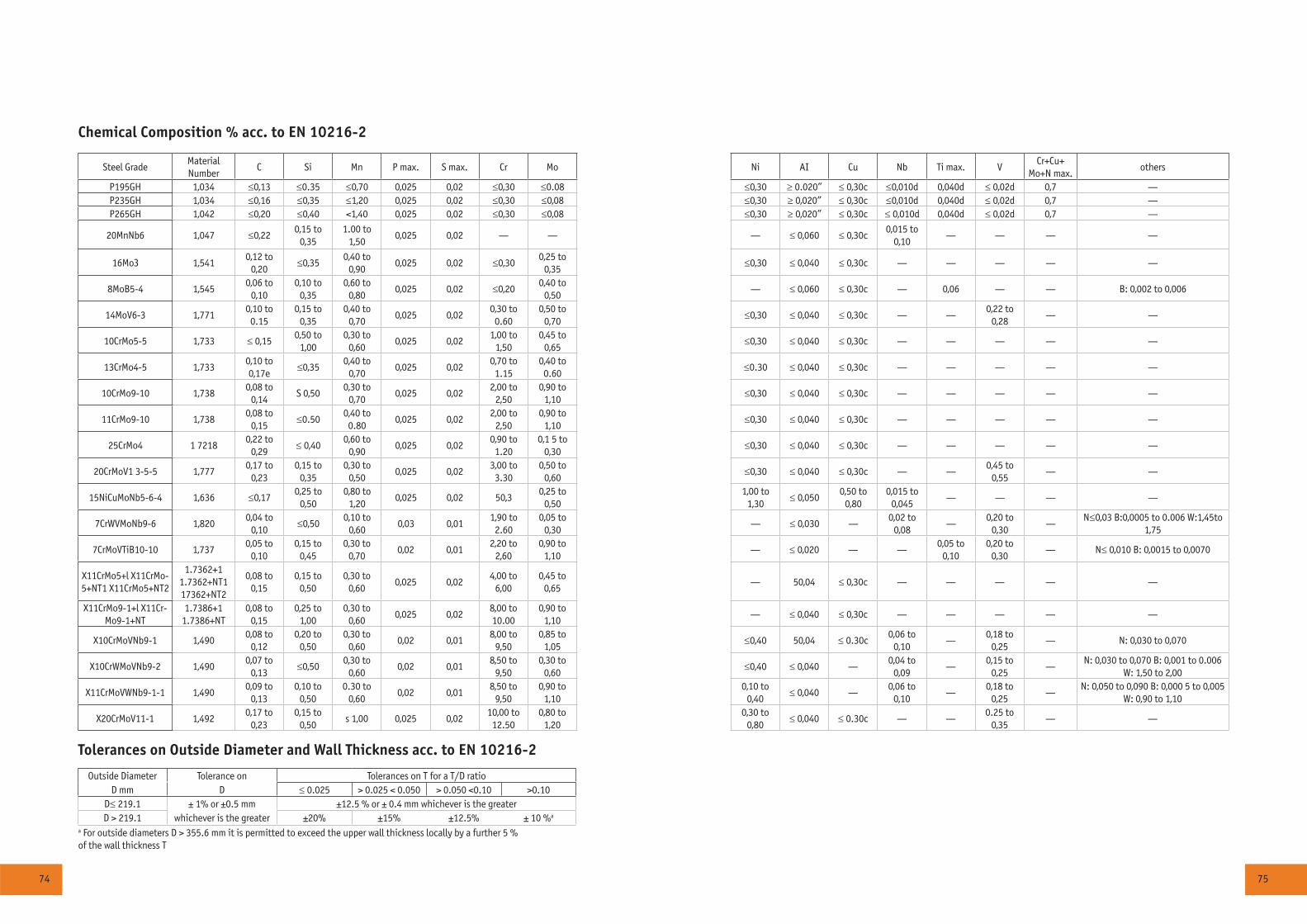
74 75
Chemical Composition % acc. to EN 10216-2
Steel GradeMaterial Number
Ñ Si Ìn Ð max. S max. Cr Ìî Ni AI Ñu Nb Ti max. VÑr+Ñu+
Mo+N max.others
P195GH 1,034 ≤0,13 ≤0.35 ≤0,70 0,025 0,02 ≤0,30 ≤0.08 ≤0,30 ≥ 0.020” ≤ 0,30c ≤0,010d 0,040d ≤ 0,02d 0,7 —P235GH 1,034 ≤0,16 ≤0,35 ≤1,20 0,025 0,02 ≤0,30 ≤0,08 ≤0,30 ≥ 0,020” ≤ 0,30c ≤0,010d 0,040d ≤ 0,02d 0,7 —P265GH 1,042 ≤0,20 ≤0,40 <1,40 0,025 0,02 ≤0,30 ≤0,08 ≤0,30 ≥ 0,020” ≤ 0,30c ≤ 0,010d 0,040d ≤ 0,02d 0,7 —
20MnNb6 1,047 ≤0,220,15 to
0,351.00 to
1,500,025 0,02 — — — ≤ 0,060 ≤ 0,30c
0,015 to 0,10
— — — —
16픂 1,5410,12 to
0,20≤0,35
0,40 to 0,90
0,025 0,02 ≤0,300,25 to
0,35≤0,30 ≤ 0,040 ≤ 0,30c — — — — —
8ÌîÂ5-4 1,5450,06 to
0,100,10 to
0,350,60 to
0,800,025 0,02 ≤0,20
0,40 to 0,50
— ≤ 0,060 ≤ 0,30c — 0,06 — — Â: 0,002 to 0,006
14MîV6-3 1,7710,10 to 0.15
0,15 to 0,35
0,40 to 0,70
0,025 0,020,30 to 0.60
0,50 to 0,70
≤0,30 ≤ 0,040 ≤ 0,30c — —0,22 to
0,28— —
10ÑrÌî5-5 1,733 ≤ 0,150,50 to
1,000,30 to
0,600,025 0,02
1,00 to 1,50
0,45 to 0,65
≤0,30 ≤ 0,040 ≤ 0,30c — — — — —
13ÑrÌî4-5 1,7330,10 to 0,17å
≤0,350,40 to
0,700,025 0,02
0,70 to 1.15
0,40 to 0.60
≤0.30 ≤ 0,040 ≤ 0,30c — — — — —
10ÑrÌî9-10 1,7380,08 to
0,14S 0,50
0,30 to 0,70
0,025 0,022,00 to
2,500,90 to
1,10≤0,30 ≤ 0,040 ≤ 0,30c — — — — —
11ÑrÌî9-10 1,7380,08 to
0,15≤0.50
0,40 to 0.80
0,025 0,022,00 to
2,500,90 to
1,10≤0,30 ≤ 0,040 ≤ 0,30c — — — — —
25ÑrÌî4 1 72180,22 to
0,29≤ 0,40
0,60 to 0,90
0,025 0,020,90 to 1.20
0,1 5 to 0,30
≤0,30 ≤ 0,040 ≤ 0,30c — — — — —
20CrMoV1 3-5-5 1,7770,17 to
0,230,15 to
0,350,30 to
0,500,025 0,02
3,00 to 3.30
0,50 to 0,60
≤0,30 ≤ 0,040 ≤ 0,30c — —0,45 to
0,55— —
15NiCuMoNb5-6-4 1,636 ≤0,170,25 to
0,500,80 to
1,200,025 0,02 50,3
0,25 to 0,50
1,00 to 1,30
≤ 0,0500,50 to
0,800,015 to
0,045— — — —
7CrWVMoNb9-6 1,8200,04 to
0,10≤0,50
0,10 to 0,60
0,03 0,011,90 to 2.60
0,05 to 0,30
— ≤ 0,030 —0,02 to
0,08—
0,20 to 0,30
—N≤0,03 Â:0,0005 to 0.006 W:1,45to
1,75
7CrMoVTiB10-10 1,7370,05 to
0,100,15 to
0,450,30 to
0,700,02 0,01
2,20 to 2,60
0,90 to 1,10
— ≤ 0,020 — —0,05 to
0,100,20 to
0,30— N≤ 0,010 Â: 0,0015 to 0,0070
X11CrMo5+l X11CrMo-5+NT1 X11CrMo5+NT2
1.7362+1 1.7362+NT1 17362+NT2
0,08 to 0,15
0,15 to 0,50
0,30 to 0,60
0,025 0,024,00 to
6,000,45 to
0,65— 50,04 ≤ 0,30c — — — — —
X11CrMo9-1+l X11Cr-Mo9-1+NT
1.7386+1 1.7386+NT
0,08 to 0,15
0,25 to 1,00
0,30 to 0,60
0,025 0,028,00 to 10.00
0,90 to 1,10
— ≤ 0,040 ≤ 0,30c — — — — —
X10CrMoVNb9-1 1,4900,08 to
0,120,20 to
0,500,30 to
0,600,02 0,01
8,00 to 9,50
0,85 to 1,05
≤0,40 50,04 ≤ 0.30c0,06 to
0,10—
0,18 to 0,25
— N: 0,030 to 0,070
X10CrWMoVNb9-2 1,4900,07 to
0,13≤0,50
0,30 to 0,60
0,02 0,018,50 to
9,500,30 to
0,60≤0,40 ≤ 0,040 —
0,04 to 0,09
—0,15 to
0,25—
N: 0,030 to 0,070 Â: 0,001 to 0.006 W: 1,50 to 2,00
X11CrMoVWNb9-1-1 1,4900,09 to
0,130,10 to
0,500.30 to
0,600,02 0,01
8,50 to 9,50
0,90 to 1,10
0,10 to 0,40
≤ 0,040 —0,06 to
0,10—
0,18 to 0,25
—N: 0,050 to 0,090 Â: 0,000 5 to 0,005
W: 0,90 to 1,10
X20CrMoV11-1 1,4920,17 to
0,230,15 to
0,50s 1,00 0,025 0,02
10,00 to 12.50
0,80 to 1,20
0,30 to 0,80
≤ 0,040 ≤ 0.30c — —0.25 to
0,35— —
Tolerances on Outside Diameter and Wall Thickness acc. to EN 10216-2
Outside Diameter Tolerance on Tolerances on T for a T/D ratioD mm D ≤ 0.025 > 0.025 < 0.050 > 0.050 <0.10 >0.10
D≤ 219.1 ± 1% or ±0.5 mm ±12.5 % or ± 0.4 mm whichever is the greaterD > 219.1 whichever is the greater ±20% ±15% ±12.5% ± 10 %a
a For outside diameters D > 355.6 mm it is permitted to exceed the upper wall thickness locally by a further 5 %of the wall thickness T

76 77
Correlation Between EN and ASTM Grades
EN ASTM
EN 10216-2 A 106 A 179 A 192 A 210 A 213 A 335
P195GH Grade A low carbon low carbon
P235GH
P265GH Grade B Grade A1
Grade C Grade C
20MnNb6
16픂 P1
8ÌîÂ5-4
14MoV6-3
10ÑrÌî5-5 T11 P11
13ÑrÌî4-5 T12 P12
10ÑrÌî9-10 T22 P22
11ÑrÌî9-10
25ÑrÌî4
20CrMoV 13-5-5
15NiCuMoNb5-6-4 T36 P36
7CrWVMoNb9-6
7CrMoVTiB10-10
X11CrMo5+I T5 P5
XllCrMo5+NTl
XllCrMo5+NT2
X11CrMo9-1+I T9 P9
XllCrMo9-l+NT
X10CrMoVNb9-1 T91 P91
X10CrWMoVNb9-2 T92 P92
XllCrMoWVNb9-1-1 T911 P911
X20CrMoVll-l
Dimensional Range acc. to ASTM 106
OD
mm
Wall Thickness, mm
1,65 2,0 3,0 3,5 4,0 4,5 5,0 5,6 6,3 7,1 8,0 8,8 10,0 11,0 12,5 14,2 16,0 17,5 20,0 22,2 25,0 28,0 30,0
10,3
13,7
17,1
21,3
26,7
33,4
42,4
44,5
48,3
51,0
54,3
57,0
60,3
63,5
70,0
73,0
76,1
82,5
88,9
101,6
108,0
114,3
127,0
133,0
139,7
141,3
152,4
159,0
168,3
177,8
193,7
219,1
244,5
273,0
323,9
355,6
406,4
TMK Scheduled
- Cold drawn
- Hot Rolled
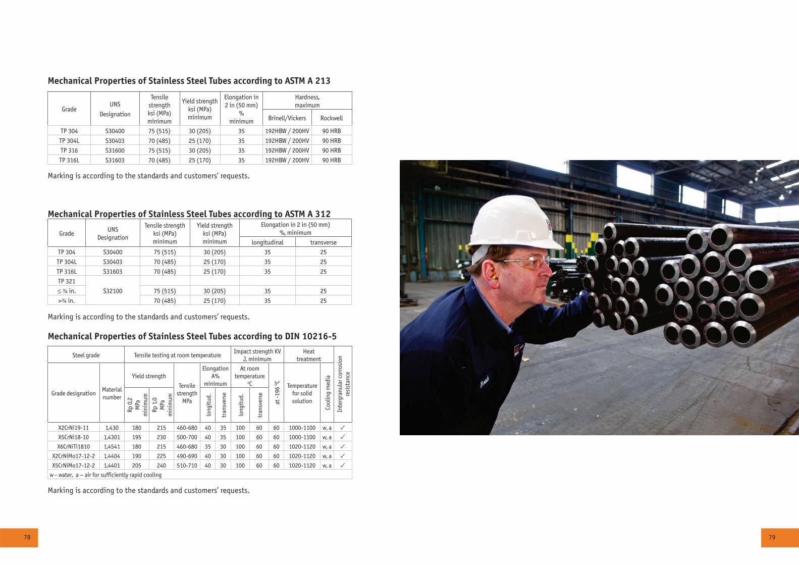
78 79
Mechanical Properties of Stainless Steel Tubes according to DIN 10216-5
Steel grade Tensile testing at room temperatureImpact strength KV
J, minimumHeat
treatment
Inte
rgra
nula
r cor
rosi
onre
sist
ance
Grade designationMaterial number
Yield strength
Tensile strength
MPa
Elongation A%
minimum
At roomtemperature
îC
at -1
96 O C
Temperature for solid solution
Cool
ing
med
ia
Rp 0
,2M
Pam
inim
um
Rp 1
,0M
Pam
inim
um
long
itud
.
tran
sver
se
long
itud
.
tran
sver
se
X2CrNi19-11 1,430 180 215 460-680 40 35 100 60 60 1000-1100 w, a ✓X5CrNi18-10 1,4301 195 230 500-700 40 35 100 60 60 1000-1100 w, a ✓X6CrNiTi1810 1,4541 180 215 460-680 35 30 100 60 60 1020-1120 w, a ✓
X2CrNiMo17-12-2 1,4404 190 225 490-690 40 30 100 60 60 1020-1120 w, a ✓X5CrNiMo17-12-2 1,4401 205 240 510-710 40 30 100 60 60 1020-1120 w, a ✓
w - water, a – air for sufficiently rapid cooling
Marking is according to the standards and customers’ requests.
Mechanical Properties of Stainless Steel Tubes according to ASTM A 312
GradeUNS
Designation
Tensile strengthksi (MPa)minimum
Yield strengthksi (MPa)minimum
Elongation in 2 in (50 mm)%, minimum
longitudinal transverse
TP 304 S30400 75 (515) 30 (205) 35 25
TP 304L S30403 70 (485) 25 (170) 35 25
TP 316L S31603 70 (485) 25 (170) 35 25
TP 321
S32100≤ ⅜ in. 75 (515) 30 (205) 35 25
>⅜ in. 70 (485) 25 (170) 35 25
Marking is according to the standards and customers’ requests.
Mechanical Properties of Stainless Steel Tubes according to ASTM A 213
GradeUNS
Designation
Tensilestrengthksi (MPa)minimum
Yield strengthksi (MPa)minimum
Elongation in2 in (50 mm)
%minimum
Hardness,maximum
Brinell/Vickers Rockwell
TP 304 S30400 75 (515) 30 (205) 35 192HBW / 200HV 90 HRB
TP 304L S30403 70 (485) 25 (170) 35 192HBW / 200HV 90 HRB
TP 316 S31600 75 (515) 30 (205) 35 192HBW / 200HV 90 HRB
TP 316L S31603 70 (485) 25 (170) 35 192HBW / 200HV 90 HRB
Marking is according to the standards and customers’ requests.
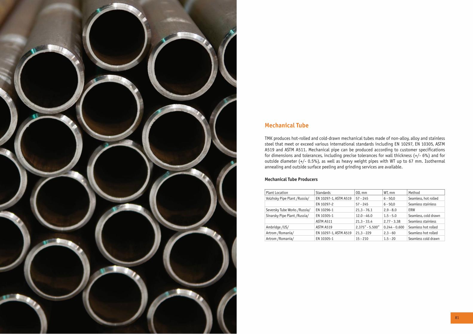
80 81
Mechanical Tube
TMK produces hot-rolled and cold-drawn mechanical tubes made of non-alloy, alloy and stainless steel that meet or exceed various international standards including EN 10297, EN 10305, ASTM A519 and ASTM A511. Mechanical pipe can be produced according to customer specifications for dimensions and tolerances, including precise tolerances for wall thickness (+/- 6%) and for outside diameter (+/- 0.5%), as well as heavy weight pipes with WT up to 67 mm. Isothermal annealing and outside surface peeling and grinding services are available.
Mechanical Tube Producers
Plant Location Standards OD, mm WT, mm Method
Volzhsky Pipe Plant /Russia/ EN 10297-1, ASTM A519 57 - 245 6 - 50,0 Seamless, hot rolled
EN 10297-2 57 - 245 6 - 50,0 Seamless stainless
Seversky Tube Works /Russia/ EN 10296-1 21.3 - 76.1 2.9 - 8.0 ERW
Sinarsky Pipe Plant /Russia/ EN 10305-1 12.0 - 46.0 1.5 - 5.0 Seamless, cold drawn
ASTM A511 21.3 - 33.4 2.77 - 3.38 Seamless stainless
Ambridge /US/ ASTM A519 2.375” - 5.500” 0.244 - 0.600 Seamless hot rolled
Artrom /Romania/ EN 10297-1, ASTM A519 21.3 - 229 2.3 - 60 Seamless hot rolled
Artrom /Romania/ EN 10305-1 15 - 210 1.5 - 20 Seamless cold drawn
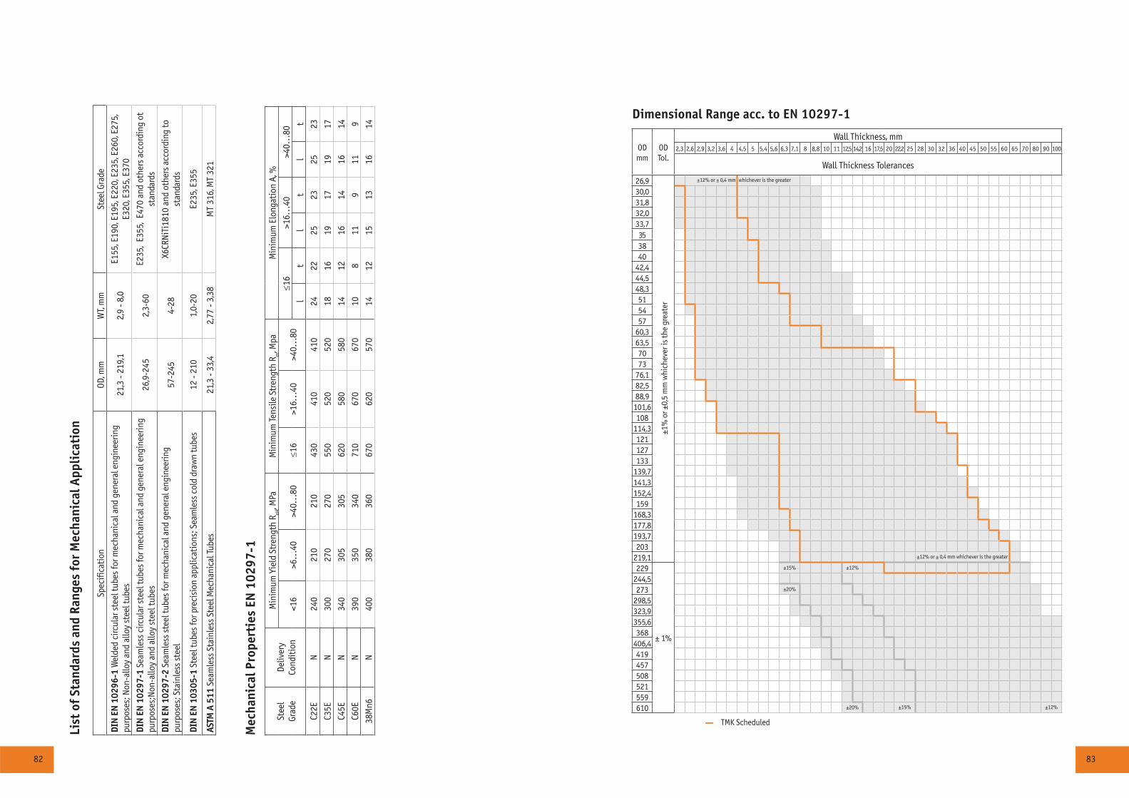
82 83
Mec
hani
cal P
rope
rtie
s EN
102
97-1
Stee
lGr
ade
Deliv
ery
Cond
itio
n
Min
imum
Yie
ld S
tren
gth
R eH, M
Pa
Min
imum
Tens
ile S
tren
gth
R m, M
paM
inim
um E
long
atio
n A,
%
<16
>6..
.40
>40.
..80
≤16
>16.
..40
>40.
..80
≤16
>16…
40>4
0…80
lt
lt
lt
Ñ22Å
N24
021
021
043
041
041
024
2225
2325
23
Ñ35Å
N30
027
027
055
052
052
018
1619
1719
17
Ñ45Å
N34
030
530
562
058
058
014
1216
1416
14
Ñ60Å
N39
035
034
071
067
067
010
811
911
9
38Ì
n6N
400
380
360
670
620
570
1412
1513
1614
List
of
Stan
dard
s an
d Ra
nges
for
Mec
hani
cal A
ppli
cati
on
Spec
ifica
tion
OD, m
mW
T, m
mSt
eel G
rade
DIN
EN
102
96-1
Wel
ded
circ
ular
ste
el tu
bes
for m
echa
nica
l and
gen
eral
eng
inee
ring
purp
oses
; Non
-allo
y an
d al
loy
stee
l tub
es21
,3 -
219,
12,
9 - 8
,0Å1
55, Å
190,
Å19
5, Å
220,
Å23
5, Å
260,
Å27
5,
Å320
, Å35
5, Å
370
DIN
EN
102
97-1
Sea
mle
ss c
ircul
ar s
teel
tube
s fo
r mec
hani
cal a
nd g
ener
al e
ngin
eerin
g pu
rpos
es;N
on-a
lloy
and
allo
y st
eel t
ubes
26,9
-245
2,3-
60Å2
35,
Å355
, Å4
70 a
nd o
ther
s ac
cord
ing
ot
stan
dard
s
DIN
EN
102
97-2
Sea
mle
ss s
teel
tube
s fo
r mec
hani
cal a
nd g
ener
al e
ngin
eerin
g pu
rpos
es; S
tain
less
ste
el57
-245
4-28
X6CR
NiT
i181
0 an
d ot
hers
acc
ordi
ng to
st
anda
rds
DIN
EN
103
05-1
Ste
el tu
bes
for p
reci
sion
app
licat
ions
; Sea
mle
ss c
old
draw
n tu
bes
12 -
210
1,0-
20Å2
35, Å
355
ASTM
A 5
11 S
eam
less
Sta
inle
ss S
teel
Mec
hani
cal T
ubes
21,3
- 33
,42,
77 -
3,38
MÒ
316,
ÌÒ
321
Dimensional Range acc. to EN 10297-1
ODmm
ODTol.
Wall Thickness, mm2,3 2,6 2,9 3,2 3,6 4 4,5 5 5,4 5,6 6,3 7,1 8 8,8 10 11 12,5 14,2 16 17,5 20 22,2 25 28 30 32 36 40 45 50 55 60 65 70 80 90 100
Wall Thickness Tolerances
26,9
±1%
or ±
0,5
mm
whi
chev
er is
the
grea
ter
±12% or ± 0,4 mm whichever is the greater
30,031,832,033,7353840
42,444,548,3515457
60,363,57073
76,182,588,9
101,6108
114,3121127133
139,7141,3152,4159
168,3177,8193,7203
219,1 ±12% or ± 0,4 mm whichever is the greater
229
± 1%
±15% ±12%
244,5273 ±20%
298,5323,9355,6368
406,4419457508521559610 ±20% ±15% ±12%
— TMK Scheduled
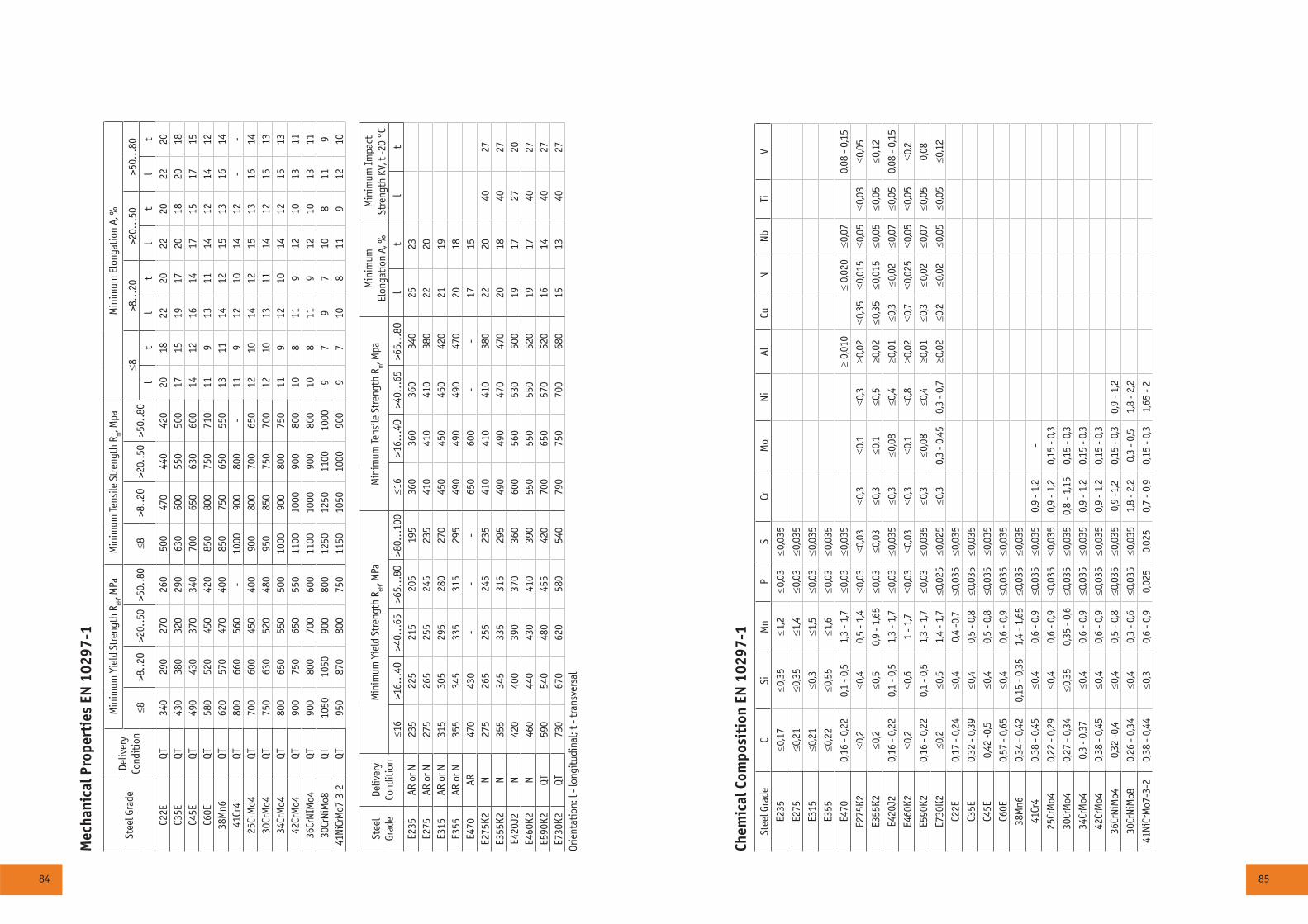
84 85
Chem
ical
Com
posi
tion
EN
102
97-1
Stee
l Gra
deC
SiM
nP
SCr
Mo
Ni
AlCu
NN
bTi
V
Å235
≤0,1
7≤0
,35
≤1,2
≤0,0
3≤0
,035
Å275
≤0,2
1≤0
,35
≤1,4
≤0,0
3≤0
,035
Å315
≤0,2
1≤0
,3≤1
,5≤0
,03
≤0,0
35
Å355
≤0,2
2≤0
,55
≤1,6
≤0,0
3≤0
,035
Å470
0,16
- 0,
220,
1 - 0
,51,
3 - 1
,7≤0
,03
≤0,0
35≥
0,01
0≤
0,02
0≤0
,07
0,08
- 0,
15
Å275
Ê2≤0
,2≤0
,40,
5 - 1
,4≤0
,03
≤0,0
3≤0
,3≤0
,1≤0
,3≥0
,02
≤0,3
5≤0
,015
≤0,0
5≤0
,03
≤0,0
5
Å355
Ê2≤0
,2≤0
,50,
9 - 1
,65
≤0,0
3≤0
,03
≤0,3
≤0,1
≤0,5
≥0,0
2≤ 0
,35
≤0,0
15≤0
,05
≤0,0
5≤0
,12
E420
J20,
16 -
0,22
0,1
- 0,5
1,3
- 1,7
≤0,0
3≤0
,035
≤0,3
≤0,0
8≤0
,4≥0
,01
≤0,3
≤0,0
2≤0
,07
≤0,0
50,
08 -
0,15
Å460
Ê2≤0
,2≤0
,61
- 1,7
≤0,0
3≤0
,03
≤0,3
≤0,1
≤0,8
≥0,0
2≤0
,7≤0
,025
≤0,0
5≤0
,05
≤0,2
Å590
Ê20,
16 -
0,22
0,1
- 0,5
1,3
- 1,7
≤0,0
3≤0
,035
≤0,3
≤0,0
8≤0
,4≥0
,01
≤0,3
≤0,0
2≤0
,07
≤0,0
50,
08
Å730
Ê2≤0
,2≤0
,51,
4 - 1
,7≤0
,025
≤0,0
25≤0
,30,
3 - 0
,45
0,3
- 0,7
≥0,0
2≤0
,2≤0
,02
≤0,0
5≤0
,05
≤0,1
2
Ñ22Å
0,17
- 0,
24≤0
,40,
4 -0
,7≤0
,035
≤0,0
35
Ñ35Å
0,32
- 0,
39≤0
,40,
5 - 0
,8≤0
,035
≤0,0
35
Ñ45Å
0,42
-0,5
≤0,4
0,5
- 0,8
≤0,0
35≤0
,035
Ñ60Å
0,57
- 0,
65≤0
,40,
6 - 0
,9≤0
,035
≤0,0
35
38Ì
n60,
34 -
0,42
0,15
- 0,
351,
4 - 1
,65
≤0,0
35≤0
,035
41Ñr
40,
38 -
0,45
≤0,4
0,6
- 0,9
≤0,0
35≤0
,035
0,9
- 1,2
-
25Ñr
Ìî4
0,22
- 0,
29≤0
,40,
6 - 0
,9≤0
,035
≤0,0
350,
9 - 1
,20,
15 -
0,3
30Ñr
Ìî4
0,27
- 0,
34≤0
,35
0,35
- 0,
6≤0
,035
≤0,0
350,
8 - 1
,15
0,15
- 0,
3
34Ñr
Ìî4
0,3
- 0,3
7≤0
,40,
6 - 0
,9≤0
,035
≤0,0
350,
9 - 1
,20,
15 -
0,3
42Ñr
Ìî4
0,38
- 0,
45≤0
,40,
6 - 0
,9≤0
,035
≤0,0
350,
9 - 1
,20,
15 -
0,3
36Cr
NiM
o40,
32 -0
,4≤0
,40,
5 - 0
,8≤0
,035
≤0,0
350,
9 -1
,20,
15 -
0,3
0,9
- 1,2
30Cr
NiM
o80,
26 -
0,34
≤0,4
0,3
- 0,6
≤0,0
35≤0
,035
1,8
- 2,2
0,3
- 0,5
1,8
- 2,2
41N
iCrM
o7-3
-20,
38 -
0,44
≤0,3
0,6
- 0,9
0,02
50,
025
0,7
- 0,9
0,15
- 0,
31,
65 -
2
Mec
hani
cal P
rope
rtie
s EN
102
97-1
Stee
l Gra
deDe
liver
yCo
ndit
ion
Min
imum
Yie
ld S
tren
gth
R eH, M
Pa
Min
imum
Tens
ile S
tren
gth
R m, M
paM
inim
um E
long
atio
n A,
%
≤8>8
..2Î
>20.
.50
>50.
.80
≤8>8
..2Î
>20.
.50
>50.
.80
≤8>8
...2
0>2
0…50
>50…
80
lt
lt
lt
lt
Ñ22Å
QT34
029
027
026
050
047
044
042
020
1822
2022
2022
20Ñ3
5ÅQT
430
380
320
290
630
600
550
500
1715
1917
2018
2018
Ñ45Å
QT49
043
037
034
070
065
063
060
014
1216
1417
1517
15Ñ6
0ÅQT
580
520
450
420
850
800
750
710
119
1311
1412
1412
38Ì
n6QT
620
570
470
400
850
750
650
550
1311
1412
1513
1614
41Ñã
4QT
800
660
560
-10
0090
080
0-
119
1210
1412
--
25Ñã
Ìî4
QT70
060
045
040
090
080
070
065
012
1014
1215
1316
1430
ÑãÌ
î4QT
750
630
520
480
950
850
750
700
1210
1311
1412
1513
34Ñã
Ìî4
QT80
065
055
050
010
0090
080
075
011
912
1014
1215
1342
ÑãÌ
î4QT
900
750
650
550
1100
1000
900
800
108
119
1210
1311
36Cr
NIM
o4QT
900
800
700
600
1100
1000
900
800
108
119
1210
1311
30Cr
NiM
o8QT
1050
1050
900
800
1250
1250
1100
1000
97
97
108
119
41Ni
CrM
o7-3
-2QT
950
870
800
750
1150
1050
1000
900
97
108
119
1210
Stee
l Gr
ade
Deliv
ery
Cond
itio
nM
inim
um Y
ield
Str
engt
h R eH
, MPa
M
inim
um Te
nsile
Str
engt
h R m
, Mpa
Min
imum
Elon
gati
on A
, %M
inim
um I
mpa
ct
Stre
ngth
KV,
t -2
0 °Ñ
≤16
>16.
..4Î
>40.
..65
>65.
..8Î
>80.
..10
0≤1
6>1
6...
4Î>4
0...
65>6
5...
8Îl
tl
tÅ2
35AR
or N
235
225
215
205
195
360
360
360
340
2523
Å275
AR o
r N27
526
525
524
523
541
041
041
038
022
20Å3
15AR
or N
315
305
295
280
270
450
450
450
420
2119
Å355
AR o
r N35
534
533
531
529
549
049
049
047
020
18Å4
70AR
470
430
--
-65
060
0-
-17
15Å2
75Ê2
N27
526
525
524
523
541
041
041
038
022
2040
27Å3
55Ê2
N35
534
533
531
529
549
049
047
047
020
1840
27E4
20J2
N42
040
039
037
036
060
056
053
050
019
1727
20Å4
60Ê2
N46
044
043
041
039
055
055
055
052
019
1740
27Å5
90Ê2
QT59
054
048
045
542
070
065
057
052
016
1440
27Å7
30Ê2
QT73
067
062
058
054
079
075
070
068
015
1340
27Or
ient
atio
n: l
- lon
gitu
dina
l; t -
tran
sver
sal
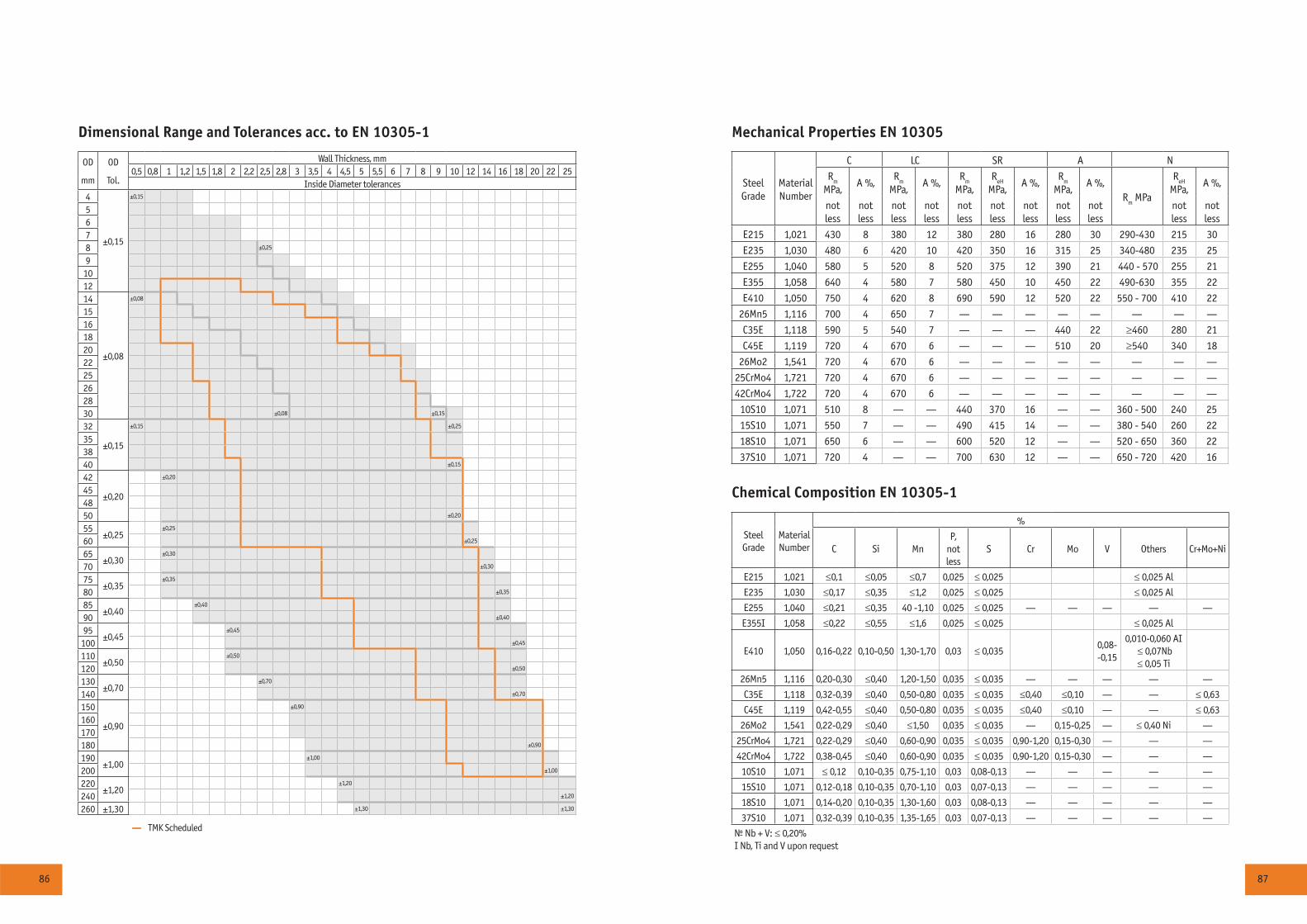
86 87
Chemical Composition EN 10305-1
Steel Grade
Material Number
%
Ñ Si ÌnÐ,
not less
S Ñr Ìî V Others Cr+Mo+Ni
Å215 1,021 ≤0,1 ≤0,05 ≤0,7 0,025 ≤ 0,025 ≤ 0,025 Al
Å235 1,030 ≤0,17 ≤0,35 ≤1,2 0,025 ≤ 0,025 ≤ 0,025 Al
Å255 1,040 ≤0,21 ≤0,35 40 -1,10 0,025 ≤ 0,025 — — — — —
Å355² 1,058 ≤0,22 ≤0,55 ≤1,6 0,025 ≤ 0,025 ≤ 0,025 Al
Å410 1,050 0,16-0,22 0,10-0,50 1,30-1,70 0,03 ≤ 0,0350,08- -0,15
0,010-0,060 AI ≤ 0,07Nb ≤ 0,05 Ti
26Ìn5 1,116 0,20-0,30 ≤0,40 1,20-1,50 0,035 ≤ 0,035 — — — — —
Ñ35Å 1,118 0,32-0,39 ≤0,40 0,50-0,80 0,035 ≤ 0,035 ≤0,40 ≤0,10 — — ≤ 0,63
Ñ45Å 1,119 0,42-0,55 ≤0,40 0,50-0,80 0,035 ≤ 0,035 ≤0,40 ≤0,10 — — ≤ 0,63
26Ìî2 1,541 0,22-0,29 ≤0,40 ≤1,50 0,035 ≤ 0,035 — 0,15-0,25 — ≤ 0,40 Ni —
25ÑrÌî4 1,721 0,22-0,29 ≤0,40 0,60-0,90 0,035 ≤ 0,035 0,90-1,20 0,15-0,30 — — —
42ÑrÌî4 1,722 0,38-0,45 ≤0,40 0,60-0,90 0,035 ≤ 0,035 0,90-1,20 0,15-0,30 — — —
10S10 1,071 ≤ 0,12 0,10-0,35 0,75-1,10 0,03 0,08-0,13 — — — — —
15S10 1,071 0,12-0,18 0,10-0,35 0,70-1,10 0,03 0,07-0,13 — — — — —
18S10 1,071 0,14-0,20 0,10-0,35 1,30-1,60 0,03 0,08-0,13 — — — — —
37S10 1,071 0,32-0,39 0,10-0,35 1,35-1,65 0,03 0,07-0,13 — — — — —
¹ Nb + V: ≤ 0,20%² Nb, Ti and V upon request
Mechanical Properties EN 10305
Steel Grade
Material Number
Ñ LC SR À N
Rm
MPa, À %,
Rm
MPa,À %,
Rm
MPa, R
eH
MPa, À %,
Rm
MPa,À %,
Rm MPa
ReH
MPa,
À %,
notless
notless
notless
notless
notless
notless
notless
notless
notless
notless
notless
Å215 1,021 430 8 380 12 380 280 16 280 30 290-430 215 30
Å235 1,030 480 6 420 10 420 350 16 315 25 340-480 235 25
Å255 1,040 580 5 520 8 520 375 12 390 21 440 - 570 255 21
Å355 1,058 640 4 580 7 580 450 10 450 22 490-630 355 22
Å410 1,050 750 4 620 8 690 590 12 520 22 550 - 700 410 22
26Ìn5 1,116 700 4 650 7 — — — — — — — —
Ñ35Å 1,118 590 5 540 7 — — — 440 22 ≥460 280 21
Ñ45Å 1,119 720 4 670 6 — — — 510 20 ≥540 340 18
26Ìî2 1,541 720 4 670 6 — — — — — — — —
25ÑrÌî4 1,721 720 4 670 6 — — — — — — — —
42ÑrÌî4 1,722 720 4 670 6 — — — — — — — —
10S10 1,071 510 8 — — 440 370 16 — — 360 - 500 240 25
15S10 1,071 550 7 — — 490 415 14 — — 380 - 540 260 22
18S10 1,071 650 6 — — 600 520 12 — — 520 - 650 360 22
37S10 1,071 720 4 — — 700 630 12 — — 650 - 720 420 16
Dimensional Range and Tolerances acc. to EN 10305-1
OD
mm
OD
Tol.
Wall Thickness, mm0,5 0,8 1 1,2 1,5 1,8 2 2,2 2,5 2,8 3 3,5 4 4,5 5 5,5 6 7 8 9 10 12 14 16 18 20 22 25
Inside Diameter tolerances4
±0,15
±0,15
5678 ±0,25
9101214
±0,08
±0,08
151618202225262830 ±0,08 ±0,15
32
±0,15
±0,15 ±0,25
353840 ±0,15
42
±0,20
±0,20
454850 ±0,20
55±0,25
±0,25
60 ±0,25
65±0,30
±0,30
70 ±0,30
75±0,35
±0,35
80 ±0,35
85±0,40
±0,40
90 ±0,40
95±0,45
±0,45
100 ±0,45
110±0,50
±0,50
120 ±0,50
130±0,70
±0,70
140 ±0,70
150
±0,90
±0,90
160170180 ±0,90
190±1,00
±1,00
200 ±1,00
220±1,20
±1,20
240 ±1,20
260 ±1,30 ±1,30 ±1,30
— TMK Scheduled

88 89
Structurals and Standard Pipe
TMK produces hot finished structural hollow sections of non-alloy and fine grain steel according to the standard EN 10210-1,2 and cold-formed seamless and welded carbon steel structural tubing in rounds in accordance with ASTM A500.
For standard uses such as steam, gas and water supply, TMK manufactures seamless and welded tube and pipe according to ASTM A53, EN 10208-1,2, EN 10224 and EN 10255 specifications.
Producers
Plant Location Standards OD Wall Thickness Method
StructuralsVolzhsky Pipe Plant /Russia/ EN 10210 1,2 57 - 245 mm 6,0 -50 mm Seamless, hot rolled
Sinarsky Pipe Plant /Russia/ EN 10210 1,2 33,7 - 168,3 mm 2,9 - 16 mm Seamless, hot rolled
ASTM A500 23 - 76 mm 2,0 -10 mm Seamless, cold drawn
TAGMET /Russia/ EN 10210 1 114,3 - 273 mm 8,0 - 20 mm Seamless hot rolled
Blytheville /US/ ASTM A500 1.900”-4.500” 0.109”-0.337” ERW
Camanche /US/ ASTM A500 4.500” - 8.625” 0.134” - 0.500” ERW
Artrom /Romania/ EN 10210-1,2 21,3 - 219,1 mm 2,3 - 60 mm Seamless hot rolled
Standard pipeVolzhsky Pipe Plant /Russia/ ASTM A53 219,1 - 406,4 mm 7,92 - 34,8 mm Seamless
Seversky Tube Works /Russia/ ASTM A53 219,1-323,8 mm 7,92 - 23,32 mm Seamless
EN 10208-1, 10255, 10224, ASTM A53
21,3 - 530 mm 2,9 - 13 mm ERW
Sinarsky Pipe Plant /Russia/ EN 10255 33,7 - 88,9 mm 4,05 - 4,85 mm Seamless, hot rolled
EN 10255, A53 10,2 - 76,1 mm 1,73 - 9,53 mm Seamless, cold drawn
TAGMET /Russia/ EN 10255 21,3 - 60,3 mm 2,65 - 3,65 mm ERW
Ambridge /US/ ASTM A53 2.375” - 4.500” 0.218” - 0.600” Seamless
Blytheville /US/ ASTM A53 1.900”-4.500” 0.109”-0.337” ERW
Camanche /US/ ASTM A53 4.500” - 8.625” 0.134” - 0.500” ERW
Wilder /US/ ASTM A53 4.500” - 16.000” 0.188” - 0.550” ERW
Artrom /Romania/ ASTM A53 21,3 - 219,1 mm 2,3 - 25,4 mm Seamless hot rolled
EN 10255 21,3 - 114,3 mm 2,3 - 5,4 mm Seamless hot rolled
EN 10208-1,2 21,3 - 219,1 mm 2,3 - 60 mm Seamless hot rolled
Geneva, NE/US HSS - A500 2sq - 7sq 120 - 250 B, C
HSS - A500 3x2 - 8x6 120 - 250 B, C
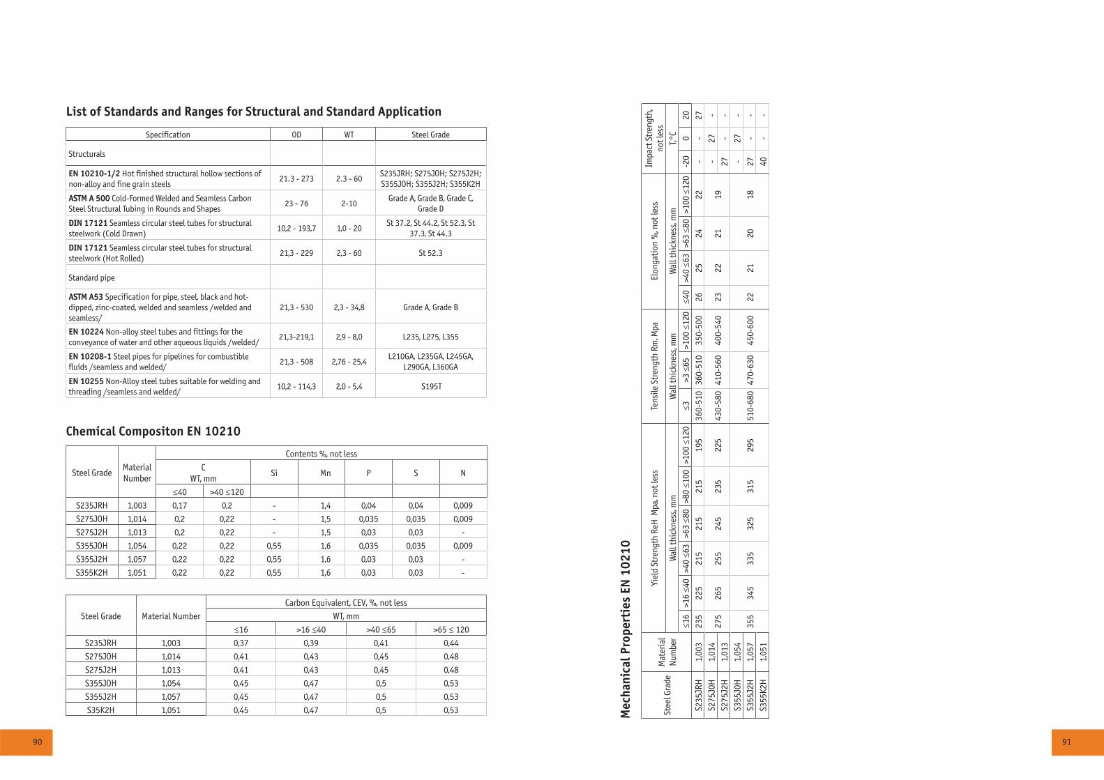
90 91
Chemical Compositon EN 10210
Steel GradeMaterial Number
Contents %, not less
CWT, mm
Si Mn Ð S N
≤40 >40 ≤120
S235JRH 1,003 0,17 0,2 - 1,4 0,04 0,04 0,009
S275JOH 1,014 0,2 0,22 - 1,5 0,035 0,035 0,009
S275J2H 1,013 0,2 0,22 - 1,5 0,03 0,03 -
S355JOH 1,054 0,22 0,22 0,55 1,6 0,035 0,035 0,009
S355J2H 1,057 0,22 0,22 0,55 1,6 0,03 0,03 -
S355K2H 1,051 0,22 0,22 0,55 1,6 0,03 0,03 -
Mec
hani
cal P
rope
rtie
s EN
102
10
Stee
l Gra
deM
ater
ial
Num
ber
Yiel
d St
reng
th R
eH M
pa, n
ot le
ssTe
nsile
Str
engt
h Rm
, Mpa
Elon
gati
on %
, not
less
Impa
ct S
tren
gth,
not l
ess
Wal
l thi
ckne
ss, m
mW
all t
hick
ness
, mm
Wal
l thi
ckne
ss, m
mT,°
C≤1
6>1
6 ≤4
0>4
0 ≤6
3>6
3 ≤8
0>8
0 ≤1
00>1
00 ≤
120
≤3>3
≤65
>100
≤12
0≤4
0>4
0 ≤6
3>6
3 ≤8
0>1
00 ≤
120
-20
020
S235
JRH
1,00
323
522
521
521
521
519
536
0-51
036
0-51
035
0-50
026
2524
22-
-27
S275
J0H
1,01
427
526
525
524
523
522
543
0-58
041
0-56
040
0-54
023
2221
19-
27-
S275
J2H
1,01
327
--
S355
J0H
1,05
435
534
533
532
531
529
551
0-68
047
0-63
045
0-60
022
2120
18-
27-
S355
J2H
1,05
727
--
S355
K2H
1,05
140
--
Steel Grade Material Number
Carbon Equivalent, CEV, %, not less
WT, mm
≤16 >16 ≤40 >40 ≤65 >65 ≤ 120
S235JRH 1,003 0,37 0,39 0,41 0,44
S275JOH 1,014 0,41 0,43 0,45 0,48
S275J2H 1,013 0,41 0,43 0,45 0,48
S355JOH 1,054 0,45 0,47 0,5 0,53
S355J2H 1,057 0,45 0,47 0,5 0,53
S35K2H 1,051 0,45 0,47 0,5 0,53
List of Standards and Ranges for Structural and Standard Application
Specification OD WT Steel Grade
Structurals
EN 10210-1/2 Hot finished structural hollow sections of non-alloy and fine grain steels
21.3 - 273 2.3 - 60S235JRH; S275JOH; S275J2H; S355JOH; S355J2H; S355K2H
ASTM A 500 Cold-Formed Welded and Seamless Carbon Steel Structural Tubing in Rounds and Shapes
23 - 76 2-10Grade A, Grade B, Grade C,
Grade D
DIN 17121 Seamless circular steel tubes for structural steelwork (Cold Drawn)
10,2 - 193,7 1,0 - 20St 37.2, St 44.2, St 52.3, St
37.3, St 44.3
DIN 17121 Seamless circular steel tubes for structural steelwork (Hot Rolled)
21,3 - 229 2,3 - 60 St 52.3
Standard pipe
ASTM A53 Specification for pipe, steel, black and hot-dipped, zinc-coated, welded and seamless /welded and seamless/
21,3 - 530 2,3 - 34,8 Grade A, Grade B
EN 10224 Non-alloy steel tubes and fittings for the conveyance of water and other aqueous liquids /welded/
21,3-219,1 2,9 - 8,0 L235, L275, L355
EN 10208-1 Steel pipes for pipelines for combustible fluids /seamless and welded/
21,3 - 508 2,76 - 25,4L210GA, L235GA, L245GA,
L290GA, L360GA
EN 10255 Non-Alloy steel tubes suitable for welding and threading /seamless and welded/
10,2 - 114,3 2,0 - 5,4 S195T
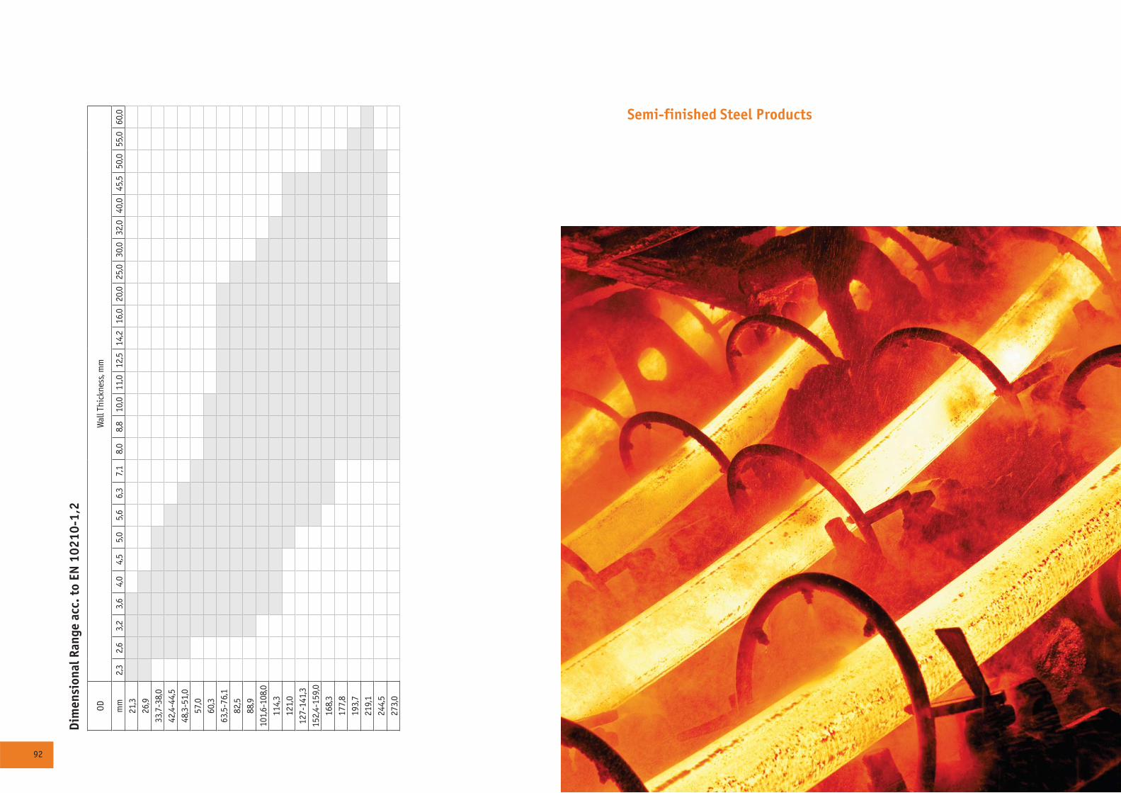
92 93
Dim
ensi
onal
Ran
ge a
cc. t
o EN
102
10-1
,2
ODW
all T
hick
ness
, mm
mm
2,3
2,6
3,2
3,6
4,0
4,5
5,0
5,6
6,3
7,1
8,0
8,8
10,0
11,0
12,5
14,2
16,0
20,0
25,0
30,0
32,0
40,0
45,5
50,0
55,0
60,0
21,3
26,9
33,7
-38,
042
,4-4
4,5
48,3
-51,
057
,060
,363
,5-7
6,1
82,5
88,9
101,
6-10
8,0
114,
312
1,0
127-
141,
315
2,4-
159,
016
8,3
177,
819
3,7
219,
124
4,5
273,
0
Semi-finished Steel Products
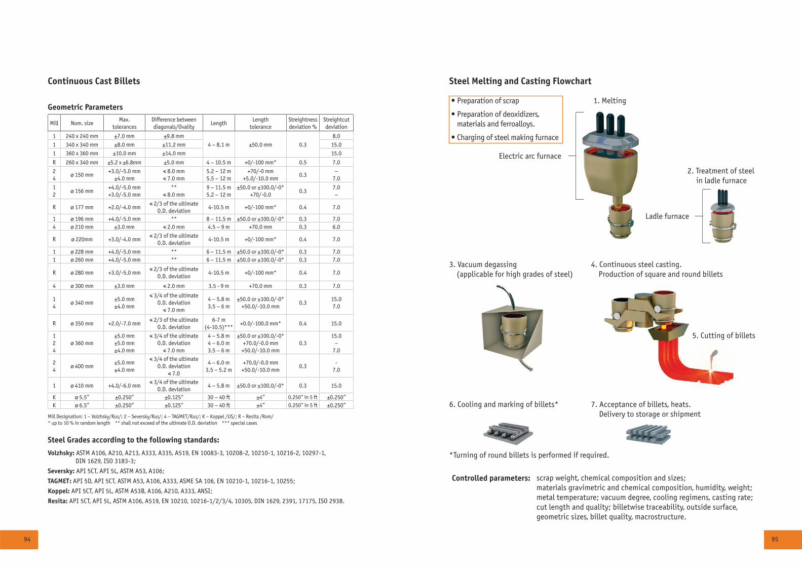
94 95
Steel Melting and Casting Flowchart
• Preparation of scrap
• Preparation of deoxidizers, materials and ferroalloys.
• Charging of steel making furnace
1. Melting
2. Treatment of steel in ladle furnace
Electric arc furnace
Ladle furnace
3. Vacuum degassing (applicable for high grades of steel)
4. Continuous steel casting. Production of square and round billets
5. Cutting of billets
6. Cooling and marking of billets* 7. Acceptance of billets, heats. Delivery to storage or shipment
Controlled parameters: scrap weight, chemical composition and sizes;materials gravimetric and chemical composition, humidity, weight; metal temperature; vacuum degree, cooling regimens, casting rate;cut length and quality; billetwise traceability, outside surface, geometric sizes, billet quality, macrostructure.
*Turning of round billets is performed if required.
Geometric Parameters
Mill Nom. sizeMax.
tolerancesDifference between diagonals/Ovality
LengthLength
toleranceStreightness deviation %
Streightcut deviation
1 240 x 240 mm ±7.0 mm ±9.8 mm
4 – 8.1 m ±50.0 mm 0.3
8.0
1 340 x 340 mm ±8.0 mm ±11.2 mm 15.0
1 360 x 360 mm ±10.0 mm ±14.0 mm 15.0
R 260 x 340 mm ±5.2 x ±6.8mm ±5.0 mm 4 – 10.5 m +0/-100 mm* 0.5 7.0
24
ø 150 mm+3.0/-5.0 mm
±4.0 mm5.2 – 12 m5.5 – 12 m
+70/-0 mm+5.0/-10.0 mm
0.3–
7.0
12
ø 156 mm+4.0/-5.0 mm+3.0/-5.0 mm
** 9 – 11.5 m5.2 – 12 m
±50.0 or ±100.0/-0*+70/-0.0
0.37.0–
R ø 177 mm +2.0/-4.0 mmO.D. deviation
4-10.5 m +0/-100 mm* 0.4 7.0
1 ø 196 mm +4.0/-5.0 mm ** 8 – 11.5 m ±50.0 or ±100.0/-0* 0.3 7.04 ø 210 mm ±3.0 mm 4.5 – 9 m +70.0 mm 0.3 6.0
R ø 220mm +3.0/-4.0 mmO.D. deviation
4-10.5 m +0/-100 mm* 0.4 7.0
1 ø 228 mm +4.0/-5.0 mm ** 6 – 11.5 m ±50.0 or ±100.0/-0* 0.3 7.01 ø 260 mm +4.0/-5.0 mm ** 6 – 11.5 m ±50.0 or ±100.0/-0* 0.3 7.0
R ø 280 mm +3.0/-5.0 mmO.D. deviation
4-10.5 m +0/-100 mm* 0.4 7.0
4 ø 300 mm ±3.0 mm 3.5 - 9 m +70.0 mm 0.3 7.0
14
ø 340 mm±5.0 mm±4.0 mm
O.D. deviation4 – 5.8 m3.5 – 6 m
±50.0 or ±100.0/-0*+50.0/-10.0 mm
0.315.07.0
R ø 350 mm +2.0/-7.0 mmO.D. deviation
6-7 m(4-10.5)***
+0.0/-100.0 mm* 0.4 15.0
124
ø 360 mm±5.0 mm±5.0 mm±4.0 mm
O.D. deviation4 – 5.8 m4 – 6.0 m3.5 – 6 m
±50.0 or ±100.0/-0*+70.0/-0.0 mm
+50.0/-10.0 mm0.3
15.0–
7.0
24
ø 400 mm±5.0 mm±4.0 mm
O.D. deviation4 – 6.0 m
3.5 – 5.2 m+70.0/-0.0 mm
+50.0/-10.0 mm0.3
-7.0
1 ø 410 mm +4.0/-6.0 mmO.D. deviation
4 – 5.8 m ±50.0 or ±100.0/-0* 0.3 15.0
K ø 5.5” ±0.250” ±0.125” 30 – 40 ft ±4” 0.250” in 5 ft ±0.250”K ø 6.5” ±0.250” ±0.125” 30 – 40 ft ±4” 0.250” in 5 ft ±0.250”
Volzhsky: ASTM A106, A210, A213, A333, A335, A519, EN 10083-3, 10208-2, 10210-1, 10216-2, 10297-1, DIN 1629, ISO 3183-3;
Seversky: API 5CT, API 5L, ASTM A53, A106;
TAGMET: API 5D, API 5CT, ASTM A53, A106, A333, ASME SA 106, EN 10210-1, 10216-1, 10255;
Koppel: API 5CT, API 5L, ASTM A53B, A106, A210, A333, ANSI;
Resita: API 5CT, API 5L, ASTM A106, A519, EN 10210, 10216-1/2/3/4, 10305, DIN 1629, 2391, 17175, ISO 2938.
Mill Designation: 1 – Volzhsky/Rus/; 2 – Seversky/Rus/; 4 – TAGMET/Rus/; K – Koppel /US/; R – Resita /Rom/ * up to 10 % in random length ** shall not exceed of the ultimate O.D. deviation *** special cases
Steel Grades according to the following standards:
Continuous Cast Billets
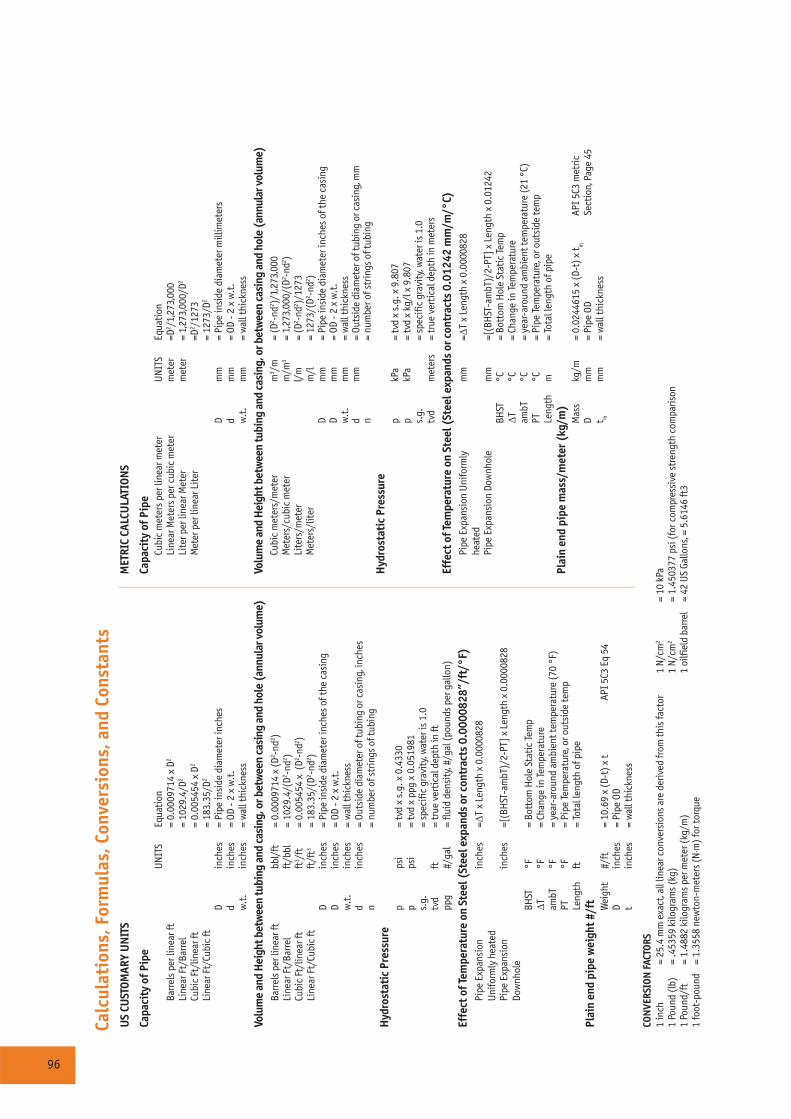
96
Calc
ulat
ions
, For
mul
as, C
onve
rsio
ns, a
nd C
onst
ants
US
CUST
OMAR
Y U
NIT
S
Capa
city
of P
ipe
UN
ITS
Equa
tion
Barr
els
per l
inea
r ft
= 0.
0009
714
x D2
Line
ar F
t/Ba
rrel
= 10
29.4
/D2
Cubi
c Ft
/lin
ear f
t=
0.00
5454
x D
2
Line
ar F
t/Cu
bic
ft=
183.
35/D
2
Din
ches
= Pi
pe in
side
dia
met
er in
ches
din
ches
= OD
- 2
x w
.t.
w.t
.in
ches
= w
all t
hick
ness
Volu
me
and
Hei
ght b
etw
een
tubi
ng a
nd c
asin
g, o
r bet
wee
n ca
sing
and
hol
e (a
nnul
ar v
olum
e)Ba
rrel
s pe
r lin
ear f
tbb
l/ft
= 0.
0009
714
x (D
2 -nd2 )
Line
ar F
t/Ba
rrel
ft/b
bl=
1029
.4/(
D2 -nd2 )
Cubi
c Ft
/lin
ear f
tft
3 /ft
= 0.
0054
54 x
(D2 -n
d2 )Li
near
Ft/
Cubi
c ft
ft/f
t3=
183.
35/(
D2 -nd2 )
Din
ches
= Pi
pe in
side
dia
met
er in
ches
of t
he c
asin
gD
inch
es=
OD -
2 x
w.t
.w
.t.
inch
es=
wal
l thi
ckne
ssd
inch
es=
Outs
ide
diam
eter
of t
ubin
g or
cas
ing,
inch
esn
= nu
mbe
r of s
trin
gs o
f tub
ing
Hyd
rost
atic
Pre
ssur
ep
psi
= tv
d x
s.g.
x 0
.433
0p
psi
= tv
d x
ppg
x 0.
0519
81s.
g.=
spec
ific
grav
ity,
wat
er is
1.0
tvd
ft=
true
ver
tica
l dep
th in
ftpp
g#/
gal
= flu
id d
ensi
ty, #
/gal
(pou
nds
per g
allo
n)
Effe
ct o
f Tem
pera
ture
on
Stee
l (St
eel e
xpan
ds o
r con
trac
ts 0
.000
0828
”/ft
/°F)
Pipe
Exp
ansi
on
Uni
form
ly h
eate
d in
ches
=ΔT
x Le
ngth
x 0
.000
0828
Pipe
Exp
ansi
on
Dow
nhol
ein
ches
=[(B
HST
-am
bT)/
2-PT
] x L
engt
h x
0.00
0082
8
BHST
°F=
Bott
om H
ole
Stat
ic Te
mp
ΔT°F
= Ch
ange
in Te
mpe
ratu
ream
bT°F
= ye
ar-a
roun
d am
bien
t tem
pera
ture
(70
°F)
PT°F
= Pi
pe Te
mpe
ratu
re, o
r out
side
tem
pLe
ngth
ft=
Tota
l len
gth
of p
ipe
Plai
n en
d pi
pe w
eigh
t #/f
tW
eigh
t#/
ft=
10.6
9 x
(D-t
) x t
A
PI 5
C3 E
q 54
Din
ches
= Pi
pe O
Dt
inch
es=
wal
l thi
ckne
ss
CON
VERS
ION
FAC
TORS
1 in
ch=
25.4
mm
exa
ct, a
ll lin
ear c
onve
rsio
ns a
re d
eriv
ed fr
om th
is fa
ctor
1 N
/cm
2=
10 k
Pa1
Poun
d (l
b)=
.453
59 k
ilogr
ams
(kg)
1 N
/cm
2=
1.45
0377
psi
(for
com
pres
sive
str
engt
h co
mpa
rison
1 Po
und/
ft=
1.48
82 k
ilogr
ams
per m
eter
(kg/
m)
1 oi
lfiel
d ba
rrel
= 42
US
Gallo
ns, =
5.6
146
ft3
1 fo
ot-p
ound
= 1.
3558
new
ton-
met
ers
(N·m
) for
torq
ue
MET
RIC
CALC
ULA
TION
S
Capa
city
of P
ipe
Cubi
c m
eter
s pe
r lin
ear m
eter
UN
ITS
Equa
tion
Line
ar M
eter
s pe
r cub
ic m
eter
met
er=D
2 /1,2
73,0
00Li
ter p
er li
near
Met
erm
eter
= 1,
273,
000/
D2
Met
er p
er li
near
Lit
er=D
2 /127
3=
1273
/D2
Dm
m=
Pipe
insi
de d
iam
eter
mill
imet
ers
dm
m=
OD -
2 x
w.t
.w
.t.
mm
= w
all t
hick
ness
Volu
me
and
Hei
ght b
etw
een
tubi
ng a
nd c
asin
g, o
r bet
wee
n ca
sing
and
hol
e (a
nnul
ar v
olum
e)Cu
bic
met
ers/
met
erm
3 /m=
(D2 -n
d2 )/1,
273,
000
Met
ers/
cubi
c m
eter
m/m
3=
1,27
3,00
0/(D
2 -nd2 )
Lite
rs/m
eter
l/m
= (D
2 -nd2 )/
1273
Met
ers/
liter
m/l
= 12
73/(
D2 -nd2 )
Dm
m=
Pipe
insi
de d
iam
eter
inch
es o
f the
cas
ing
Dm
m=
OD -
2 x
w.t
.w
.t.
mm
= w
all t
hick
ness
dm
m=
Outs
ide
diam
eter
of t
ubin
g or
cas
ing,
mm
n=
num
ber o
f str
ings
of t
ubin
gH
ydro
stat
ic P
ress
ure
pkP
a=
tvd
x s.
g. x
9.8
07p
kPa
= tv
d x
kg/l
x 9
.807
s.g.
= sp
ecifi
c gr
avit
y, w
ater
is 1
.0tv
dm
eter
s=
true
ver
tica
l dep
th in
met
ers
Effe
ct o
f Tem
pera
ture
on
Stee
l (St
eel e
xpan
ds o
r con
trac
ts 0
.012
42 m
m/m
/°C)
Pipe
Exp
ansi
on U
nifo
rmly
he
ated
m
m=Δ
T x
Leng
th x
0.0
0008
28
Pipe
Exp
ansi
on D
ownh
ole
mm
=[(B
HST
-am
bT)/
2-PT
] x L
engt
h x
0.01
242
BHST
°C=
Bott
om H
ole
Stat
ic Te
mp
ΔT°C
= Ch
ange
in Te
mpe
ratu
ream
bT°C
= ye
ar-a
roun
d am
bien
t tem
pera
ture
(21
°C)
PT°C
= Pi
pe Te
mpe
ratu
re, o
r out
side
tem
pLe
ngth
m=
Tota
l len
gth
of p
ipe
Plai
n en
d pi
pe m
ass/
met
er (
kg/m
)M
ass
kg/m
= 0.
0244
615
x (D
-t) x
t m
AP
I 5C
3 m
etric
Dm
m=
Pipe
OD
Sec
tion
, Pag
e 45
t mm
m=
wal
l thi
ckne
ss

Headquarters
TMK
40, bld. 2a, Pokrovka StreetMoscow, 105062, RussiaTel.: +7 495 775-76-00Fax: +7 495 [email protected]
Trade House “TMK”
40, bld. 2a, Pokrovka StreetMoscow, 105062, Russia Tel.: +7 495 775-76-00Fax: +7 495 [email protected]
TMK IPSCO
10120 Houston Oaks Dr.Houston, TX 77064 USATel.: +1 281 949-10-23Fax.: +1 281 445-40-40www.tmk-ipsco.com
Trading Subsidiaries and Representatives
TMK Middle East
P.O. Box 293534, Office 119Block 5EA, Dubai Airport Free ZoneDubai, United Arab Emirates Tel.: +9714 609-11-30Fax: +9714 [email protected]
TMK Europe GmbH
Immermannstraße 65 c, 40210 Düsseldorf, GermanyTel: +49 (0) 211/91348830 Fax: +49 (0) 211/[email protected]
TMK Italia s.r.l.
Piazza degli Affari, 1223900 Lecco, ItalyTel.: +39 0341 36-51-51Fax: + 39 0341 [email protected]
TMK-ARTROM Sales Officestr. Draganesti 30, Slatina, Olt,230119, RomaniaTel: +40 249 43-68-62, 43-46-40, 43-46-41Fax: +40 249 [email protected]
TMK Global AG
2, Bldv. Du Theatre, CH-1211 Geneva, CP 5019, SwitzerlandTel.: +41 22 818-64-66Fax: +41 22 [email protected]
TMK Singapore
10 Anson Road #33-06AInternational Plaza, Singapore 079903Tel.: +65 622-33-015Fax: +65 [email protected]
TMK China
Apt19 I, No. 48 Dongzhimenwai StreetDongcheng District, BeijingChina, ZIP 100027 Tel.: +8610 845-49-581Fax: +8610 [email protected]
TMK Africa
Office 12002, Triagle House, 22 Riebeek st, Central, Cape Town, South Africa 8001Tel.: +27 21 418 2066Fax: +27 21 418 2488
TMK Kazakhstan
20, Dostyk st., Astana, Kazakhstan, 01000 Tel: +7 (7172) 57-34-34, 57-85-32, Fax: +7 (7172) 57-85-35E-mail: [email protected]
TMK Turkmenistan
Hotel “Nebitchi”29 Archabil shaely 1939 Ashgabat, TurkmenistanTel./Fax: +99312 [email protected]
TMK Azerbaijan
22, Karabah street,Baku, Azerbaijan, AZ1008Tel./Fax: + 99412 [email protected]
TMK Uzbekistan
24 Oybek koch,Toshkent sh, Uzbekistan, 100015Tel.: +998 71 281-46-13Fax: +998 71 281-46-14
TMK GIPI
Gulf International Pipe Industry L.L.C.P.O. Box 1831, PC 130 Azaiba, Sultanate of OmanTel.: +968 246 014 00, +968 268 270 00Fax: +969 246 911 [email protected]
TMK IPSCO Sales OfficesTMK U.S. Sales Office
10120 Houston Oaks Dr.Houston, TX 77064 USATel.: +1 281 949-10-23Fax: +1 281 445-40-40
TMK Canada Sales Office150 6-th Avenue SW #3000Calgary, AB T2P 3Y7, CanadaTel.: +1 403 538-2182Fax: +1 403 538-2183


