Technical data sheet EP..R-R6+BAC Characterised control valve with sensor-operated flow control, 6-way, Internal thread, PN 25 (EPIV) • Nominal voltage AC/DC 24 V • Control modulating, communicative, hybrid • Two sequences (cooling/heating) with one 90° rotary actuator • Switching or modulating control on the water side of thermal heating/ cooling elements • For closed cold and warm water systems • Communication via BACnet MS/TP, Modbus RTU, Belimo MP-Bus or conventional control Type overview Type DN [ ] Rp [“] V’nom [ l/h] V’max low-n [ l/h] kvs theor. [ m³/h] PN [ ] EP015R-R6+BAC 15 1/2 1260 840 1.2 25 EP020R-R6+BAC 20 3/4 2340 1620 2.3 25 kvs theor.: Theoretical kvs value for pressure drop calculation Vmax low-n: Vmax for low-noise operation Technical data Electrical data Nominal voltage AC/DC 24 V Nominal voltage frequency 50/60 Hz Nominal voltage range AC 19.2...28.8 V / DC 21.6...28.8 V Power consumption in operation 2 W Power consumption in rest position 1.5 W Power consumption for wire sizing 4.5 VA Connection supply / control Cable 1 m, 6 x 0.75 mm² Parallel operation Yes (note the performance data) Functional data Torque motor 5Nm Communicative control BACnet MS/TP Modbus RTU MP-Bus Operating range Y 2...10 V Input Impedance 100 kΩ Position feedback U 2...10 V Position feedback U note Max. 1 mA Sound power level Motor 35 dB(A) Adjustable flow rate V’max 5...100% of Vnom Control accuracy ±5% (of 25...100% Vnom) @ 20°C / Glycol 0% vol. Control accuracy note ±10% (of 25...100% V’nom) ±20...10% (of 10...25% V’nom) Fluid Cold and warm water, water with glycol up to max. 50% vol. Fluid temperature 6...80°C Permissible operating pressure ps 1600 kPa Differential pressure ∆pmax 110 kPa Flow characteristic Linear Leakage rate air-bubble tight, leakage rate A (EN 12266-1) Angle of rotation note with room controller CRK24-B1 compelling sequence 1 = cooling and sequence 2 = heating Pipe connectors Internal thread according to ISO 7-1 Installation position upright to horizontal (in relation to the stem) Servicing maintenance-free Manual override with push-button, can be locked Flow measurement Measuring principle Ultrasonic volumetric flow measurement Measuring accuracy flow ±2% (of 25...100% Vnom) @ 20°C / Glycol 0% vol. www.belimo.com EP..R-R6+BAC • en-gb • 2020-02-03 • subject to changes 1
Transcript
Technical data sheet EP..R-R6+BAC
Characterised control valve with sensor-operated flow control, 6-way, Internal thread, PN 25 (EPIV)• Nominal voltage AC/DC 24 V• Control modulating, communicative,
hybrid• Two sequences (cooling/heating)
with one 90° rotary actuator• Switching or modulating control on
the water side of thermal heating/cooling elements
• For closed cold and warm water systems
• Communication via BACnet MS/TP, Modbus RTU, Belimo MP-Bus or conventional control
kvs theor.: Theoretical kvs value for pressure drop calculationVmax low-n: Vmax for low-noise operation
Technical data
Electrical data Nominal voltage AC/DC 24 V Nominal voltage frequency 50/60 Hz Nominal voltage range AC 19.2...28.8 V / DC 21.6...28.8 V Power consumption in operation 2 W Power consumption in rest position 1.5 W Power consumption for wire sizing 4.5 VA Connection supply / control Cable 1 m, 6 x 0.75 mm² Parallel operation Yes (note the performance data)
Functional data Torque motor 5Nm Communicative control BACnet MS/TP
Modbus RTUMP-Bus
Operating range Y 2...10 V Input Impedance 100 kΩ Position feedback U 2...10 V Position feedback U note Max. 1 mA Sound power level Motor 35 dB(A) Adjustable flow rate V’max 5...100% of Vnom Control accuracy ±5% (of 25...100% Vnom) @ 20°C / Glycol 0%
vol. Control accuracy note ±10% (of 25...100% V’nom)
±20...10% (of 10...25% V’nom) Fluid Cold and warm water, water with glycol up to
max. 50% vol. Fluid temperature 6...80°C Permissible operating pressure ps 1600 kPa Differential pressure ∆pmax 110 kPa Flow characteristic Linear Leakage rate air-bubble tight, leakage rate A (EN 12266-1) Angle of rotation note with room controller CRK24-B1 compelling
sequence 1 = cooling and sequence 2 = heating Pipe connectors Internal thread according to ISO 7-1 Installation position upright to horizontal (in relation to the stem) Servicing maintenance-free Manual override with push-button, can be locked
Flow measurement Measuring accuracy flow note ±6% (of 25...100% V’nom) Min. flow measurement 1% of V’nom
Safety Protection class IEC/EN III Safety Extra-Low Voltage (SELV) Degree of protection IEC/EN IP54 EMC CE according to 2014/30/EU Mode of operation Type 1 Rated impulse voltage supply / control 0.8 kV Control pollution degree 3 Ambient temperature -30...50°C Storage temperature -40...80°C Ambient humidity Max. 95% r.H., non-condensing
Materials Flow measuring pipe Brass body nickel-plated Closing element Chrome-plated brass Stem seal EPDM O-ring Seat PTFE, O-ring EPDM
Safety notes
!• This device has been designed for use in stationary heating, ventilation and air-
conditioning systems and must not be used outside the specified field of application, especially in aircraft or in any other airborne means of transport.
• Outdoor application: only possible in case that no (sea) water, snow, ice, insolation or aggressive gases interfere directly with the actuator and that is ensured that the ambient conditions remain at any time within the thresholds according to the data sheet.
• Only authorised specialists may carry out installation. All applicable legal or institutional installation regulations must be complied during installation.
• The device contains electrical and electronic components and must not be disposed of as household refuse. All locally valid regulations and requirements must be observed.
Product features
Mode of operation The final controlling device consists of three components: 6-way characterised control valve, measuring pipe with volumetric flow sensor and the actuator itself. The adjusted maximum flows for sequence 1 (V’max1) and sequence 2 (V’max2) are assigned to the positioning signal (2V/0% for sequence 1, 10 V/100% for sequence 2).The performance device can be controlled communicatively or by an analogue signal. The fluid is detected by the sensor in the measuring pipe and is applied as the flow value. The measured value is balanced with the setpoint. The actuator corrects the deviation by changing the valve position.
www.belimo.comEP..R-R6+BAC • en-gb • 2020-02-03 • subject to changes2
Definition V’nom is the maximum possible flow. (Vnom=Vnom1=Vnom2)
V’max1 is the maximum flow rate which has been set with the smallest positioning signal, 2V / 0%.V’max2 is the maximum flow rate which has been set with the greatest positioning signal, 10 V / 100%.V’max1 and V’max2 can be adjusted 5...100% of V’nom.
V’min 0% (non-variable).
10/100
5%
100% nom
max
Y / U [V/%]
4.7/33 7.3/672/0
Creep flow suppression Given the very low flow speed in the opening point, this can no longer be measured by the sensor within the required tolerance. This range is overridden electronically.
Opening sequenceThe valve remains closed until the volumetric flow required by the positioning signal Y corresponds to 1% of V’nom. The control along the valve characteristic curve is active after this value has been exceeded.
Closing sequenceThe control along the valve characteristic curve is active up to the required flow rate of 1% of V’nom. Once the level falls below this value, the flow rate is maintained at 1% of V’nom. If the level falls below the flow rate of 0.5% of V’nom required by the reference variable Y, then the valve will close.
0
1%
Y [V]
[l/h] Seq 1
0
1%
Y [V]
[l/h] Seq 2
0.5%0.5%
Parametrisable actuators The factory settings cover the most common applications.
Hydraulic balancing With the ZTH EU and the Belimo Assistant App, the maximum flow rates of sequence 1 and sequence 2 can be adjusted individually on-site in a few simple reliable steps.
Pressure compensation In cases of combined heating/cooling control elements, the fluid remains in the control element when in the closed position (no heating or cooling). The pressure of the enclosed fluid can rise or fall due to changes in fluid temperature caused by the ambient temperature. The 6-way characterised control valves have an integrated pressure relief function for the purpose of compensating for such pressure changes.The pressure relief function is active in the closed position (45°) of the valve; reliable separation of Sequences 1 and 2 continues. For additional information, consult the notes for project planning for the 6-way characterised control valve.
Accessories
Description Type
Mechanical accessories Pipe connector for ball valve DN 15 Rp 1/2” ZR2315 Pipe connector for ball valve DN 20 Rp 3/4” ZR2320 Fixing bracket for valve R30..-..-..-B2 DN 15/20 ZR-004
Description Type
Service Tools Belimo Assistant App, Smartphone app for easy commissioning, parameterising and maintenance
Belimo Assistant App
Converter Bluetooth / NFC ZIP-BT-NFC Service Tool, with ZIP-USB function ZTH EU
Electrical installation
!Notes • Connection via safety isolating transformer.
• Parallel connection of other actuators possible. Observe the performance data.• The wiring of the line for BACnet MS/TP / Modbus RTU is to be carried out in
accordance with applicable RS485 regulations.• Modbus / BACnet: Supply and communication are not galvanically isolated.
Connect earth signal of the devices with one another.
Wiring diagrams
AC/DC 24 V, modulating
1 2 3 5 6 7
DC (0)2 ... 10 V
–
T ~
+
YU DC 2 ... 10 V
Cable colours:1 = black 2 = red 3 = white 5 = orange 6 = pink 7 = grey
Operation on the MP-Bus
1 2 3 5 6 7
DC 2 ... 10 VMP
–
T ~
+
YU
Cable colours:1 = black 2 = red 3 = white 5 = orange 6 = pink 7 = grey
www.belimo.comEP..R-R6+BAC • en-gb • 2020-02-03 • subject to changes4
BACnet MS/TP / Modbus RTU
1 2 3 5 6 7
C2C1+
~
–
T
AC/DC 24 V
D+D–
1 2 3 5 6 7
C2C1+
~
–
T
AC/DC 24 V
GND
C₁ = D- = AC₂ = D+ = B
Modbus RTU / BACnet MS/TP with analogue setpoint (hybrid mode)
D–D+
1 2 3 5 6 7
C2C1+
~
–
T
AC/DC 24 V
GND
Y U
DC (0)2…10 VDC 2…10 V
C₁ = D- = A C₂ = D+ = B
Operating controls and indicators
Adaption 2
3
4
5
6
2 Push-button and LED display greenOff:
On:
Press button:
No power supply or malfuntion
In operation
Triggers angle of rotation adaptation, followed by standard mode
3 Push-button and LED display yellowOff:
Flickering:
On:
Press button:
Standard mode
BACnet / Modbus communication active
Adaptation or synchronising process active
No function
4 Gear disengagement buttonPress button:
Release button:
Gear disengages, motor stops, manual override possible
Gear engages, synchronisation starts, followed by standard mode
5 Service plugFor connecting ZTH
6 NFC logoOperated with Belimo Assistant App
Installation notes
Recommended installation positions The ball valve can be installed upright to horizontal. The ball valve may not be installed in a hanging position, i.e. with the stem pointing downwards.
90° 90°
Water quality requirements The water quality requirements specified in VDI 2035 must be adhered to.Belimo valves are regulating devices. For the valves to function correctly in the long term, they must be kept free from particle debris (e.g. welding beads during installation work). The installation of a suitable strainer is recommended.
Servicing Ball valves, rotary actuators and sensors are maintenance-free.Before any service work on the final controlling device is carried out, it is essential to isolate the rotary actuator from the power supply (by unplugging the electrical cable if necessary). Any pumps in the part of the piping system concerned must also be switched off and the appropriate slide valves closed (allow all components to cool down first if necessary and always reduce the system pressure to ambient pressure level).The system must not be returned to service until the ball valve and the rotary actuator have been correctly reassembled in accordance with the instructions and the pipeline has been refilled by professionally trained personnel.
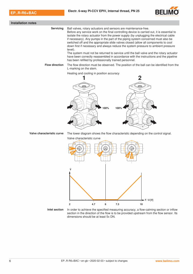
Flow direction The flow direction must be observed. The position of the ball can be identified from the L-marking on the stem.
Heating and cooling in position accuracy
100% 100%
1 2
Valve characteristic curve The lower diagram shows the flow characteristic depending on the control signal.
Valve characteristic curve
0°
45°
2 6 10
90°
Y / U [V]
4.7 7.3
30°
60°
Inlet section In order to achieve the specified measuring accuracy, a flow-calming section or inflow section in the direction of the flow is to be provided upstream from the flow sensor. Its dimensions should be at least 5x DN.
www.belimo.comEP..R-R6+BAC • en-gb • 2020-02-03 • subject to changes6
Types of installation
General notes
Valve selection The valve is determined using the maximum required flow rate V’max.A calculation of the kvs value is not required.V’max = 5…100% of V’nom
The minimum required differential pressure (pressure drop through the valve) for achieving the desired volumetric flow V’max can be calculated with the aid of the theoretical kvs value (see type overview) and the below-mentioned formula. The calculated value is dependent on the required maximum volumetric flow V’max. Higher differential pressures are compensated for automatically by the valve.
Formula
∆pmin = 100 xmax
kvs theor.
2 ∆pmin: kPamax: m3/hkvs theor.: m3/h
Example (DN15 with the desired maximum flow rate = 30% nom)
∆pmin = 100 xmax
kvs theor.
2
= 100 x = 10 kPa0.378 m3/h1.2 m3/h
2
EP015R-R6+BACkvs theor. = 1.2 m /hnom = 1260 l/h30% * 1260 l/h = 378 l/h = 0.378 m /h
3
3
Service
NFC connection Belimo equipment marked with the NFC logo can be operated with the Belimo Assistant App.
Requirement:- NFC- or Bluetooth-capable smartphone- Belimo Assistant App (Google Play & Apple AppStore)
Align NFC-capable smartphone on the actuator so that both NFC antennas are superposed.
Connect Bluetooth-enabled smartphone via the Bluetooth-to-NFC Converter ZIP-BT-NFC to the actuator. Technical data and operation instructions are shown in the ZIP-BT-NFC data sheet.