+ All Categories
Home > Documents > Technical Specification for an Underground Cable Real · PDF fileunderground cable Real Time...

Technical Specification for an Underground Cable Real · PDF fileunderground cable Real Time...

Date post: 11-Mar-2018
Category:
Upload: dinhthuan
View: 223 times
Download: 1 times
Share this document with a friend
18
Document Reference: CLNR-L151 Version: 1.0 Date of Issue: December 2014 1 Copyright Northern Powergrid (Northeast) Limited, Northern Powergrid (Yorkshire) Plc, 2014 Technical recommendation for the purchase of underground cable Real Time Thermal Rating systems 1 Purpose The purpose of this document is to set out and describe the technical requirements developed, that enabled the purchase of the various Real-time Thermal Rating (RTTR) Systems applied to Underground Cables on the Northern Powergrid power distribution networks that were trialled on the Customer-Led Network Revolution project. This recommendation is for Environmental RTTR systems which operate without a Distributed Temperature Sensing (DTS) system to directly measure the cable temperature. Unless otherwise specified, ‘cables’ in this document refers to power cables installed by burial in the ground, either directly or in ducts. Cables installed in tunnels, clipped to walls or otherwise, are not covered as the requirements are significantly different. 2 Scope This recommendation details the technical requirements for all equipment to be used in the calculation of RTTR of cables. The document applies to all equipment involved in the rating of cables including any sensors, weather stations and computing equipment (that may be located in primary or secondary sub-stations, remote servers or control rooms). The document applies to RTTR equipment at operating voltages: Low Voltage (<1000V, as specified in ENA ER 43-3); High Voltage (>1000V, < 22kV as specified in ENA ER 43-3); Extra High Voltage (22kV, < 132kV as specified in ENA ER 43-3); This recommendation includes the interfacing requirements with a remote server. A summary table of the supplier/product technical compliance is given in Appendix 1 & 2 for manufacturers to complete, detailing any variation. Manufacturers are encouraged to offer more than one option if they have a number of possible solutions. The technical requirements detailed in the main body of this document are generic. Additional site specific data will be discussed with the potential supplier.
Transcript

Document Reference: CLNR-L151 Version: 1.0 Date of Issue: December 2014 1

Copyright Northern Powergrid (Northeast) Limited, Northern Powergrid (Yorkshire) Plc, 2014

Technical recommendation for the purchase of underground cable Real Time Thermal Rating systems

1 Purpose The purpose of this document is to set out and describe the technical requirements developed, that enabled the

purchase of the various Real-time Thermal Rating (RTTR) Systems applied to Underground Cables on the

Northern Powergrid power distribution networks that were trialled on the Customer-Led Network Revolution

project.

This recommendation is for Environmental RTTR systems which operate without a Distributed Temperature

Sensing (DTS) system to directly measure the cable temperature.

Unless otherwise specified, ‘cables’ in this document refers to power cables installed by burial in the ground,

either directly or in ducts. Cables installed in tunnels, clipped to walls or otherwise, are not covered as the

requirements are significantly different.

2 Scope This recommendation details the technical requirements for all equipment to be used in the calculation of RTTR

of cables. The document applies to all equipment involved in the rating of cables including any sensors,

weather stations and computing equipment (that may be located in primary or secondary sub-stations, remote

servers or control rooms).

The document applies to RTTR equipment at operating voltages:

Low Voltage (<1000V, as specified in ENA ER 43-3);

High Voltage (>1000V, < 22kV as specified in ENA ER 43-3);

Extra High Voltage (≥ 22kV, < 132kV as specified in ENA ER 43-3);

This recommendation includes the interfacing requirements with a remote server. A summary table of the

supplier/product technical compliance is given in Appendix 1 & 2 for manufacturers to complete, detailing any

variation.

Manufacturers are encouraged to offer more than one option if they have a number of possible solutions. The

technical requirements detailed in the main body of this document are generic. Additional site specific data will

be discussed with the potential supplier.

Document Reference: CLNR-L151 Version: 1.0 Date of Issue: December 2014 2

Copyright Northern Powergrid (Northeast) Limited, Northern Powergrid (Yorkshire) Plc, 2014

Contents

1 Purpose ................................................................................................................................................1

2 Scope ...................................................................................................................................................1

2.1 Contents.........................................................................................................................................2

3 Technical Requirements ....................................................................................................................3

3.1 General ..........................................................................................................................................3

3.2 Equipment Location .......................................................................................................................3

3.3 Equipment Specification ................................................................................................................4

3.4 RTTR Model...................................................................................................................................4

3.5 Communication between System Components.............................................................................7

3.6 Safety .............................................................................................................................................7

4 References ...........................................................................................................................................8

4.1 External Documentation ................................................................................................................8

5 Definitions ............................................................................................................................................9

Appendix 1 – Schedule of Suppliers Technical Data ............................................................................ 10

Appendix 2 – Self Certification Conformance Declaration................................................................... 13

Appendix 3 – Addendum to Supplier Requirements ............................................................................ 15

Appendix 4 - Pre-commission testing, Routine Inspection and Maintenance requirements ........... 16

Appendix 5 – Electromagnetic Compatibility ........................................................................................ 17

Appendix 6 - Technical Information Check List .................................................................................... 18

Document Reference: CLNR-L151 Version: 1.0 Date of Issue: December 2014 3

Copyright Northern Powergrid (Northeast) Limited, Northern Powergrid (Yorkshire) Plc, 2014

3 Technical Requirements

3.1 General

The component constituents of an environmental cable RTTR system are given below:-

1. Measurement Device(s) (soil thermal resistivity, temperature sensors, CTs)

2. Local controllers

3. A Communications hub

4. An RTTR calculation engine

Single weather stations, soil thermal resistivity sensors, soil ambient temperature sensors and RTTR

calculation engines should be capable of being used to support multiple sites that are assessed to have similar

climatic conditions and soil thermal resistivity.

All outdoor housing for equipment should be designed to a minimum IP55 and all indoor equipment to IP52 in

accordance with BSEN 60529. Equipment for permanent installation below ground (i.e. temperature sensors)

should be designed to a minimum of IP68. The dimensions of all equipment should be specified by the

suppliers. All equipment with a real-time clock should be capable of synchronisation with an Internet

Engineering Task Force (IETF) standard Network Time Protocol version 4 (NTPv4) server.

3.2 Equipment Location

3.2.1 Current Measurements

As a minimum, current measurements should be taken for all three phases in a three-phase system. Where a

load carrying neutral conductor is present in the cable, the current in this should also be measured. Low

Voltage (LV) RTTR systems will generally make direct current measurements using split-core Rogowski Coils

and CTs as for LV load monitoring schemes. At High Voltage (HV) and Extra High Voltage (EHV),

measurements will generally be taken from protection CTs already in-situ, utilising using split-core CTs or

Rogowski coils for each of the three-phases. Sensing via the protection wiring must not involve breaking or

disconnecting protection circuits. Existing protection circuits will operate with either 1A or 5A full-scale.

Measurement of cable sheath current is preferable; however, where measurement is not practical cable sheath

current may be calculated. Cable sheath current measurements should be taken at the location at which the

cable is earthed.

3.2.2 Temperature Sensors

Temperature sensors should be in accordance with IEC 60751. Temperature sensors used to measure the

bulk (or ambient) soil temperature should be buried at the same depth to which the cable being monitored is

buried. Temperature sensors installed at locations requiring regular maintenance should have terminal ends in

underground access chambers; else terminals ends shall be left above ground. Temperature sensor probes

and cabling should be encased in non-metallic flexible ducting.

3.2.3 Thermal Resistivity Measurement

A thermal resistivity test set should be used to take reference measurements during the installation of

equipment required for UGC RTTR. A minimum of three reference measurements should be taken at the

equivalent depth to which the monitored cable(s) are buried. The average of the reference measurements

should be used as the Thermal Resistivity static-parameter. Measurements should be taken in accordance

with ASTM D5334 – 08.

Soil samples should be taken for laboratory analysis to determine:

1. The soil moisture content at time of measurement.

2. The change in soil thermal resistivity with moisture content.

Document Reference: CLNR-L151 Version: 1.0 Date of Issue: December 2014 4

Copyright Northern Powergrid (Northeast) Limited, Northern Powergrid (Yorkshire) Plc, 2014

3.3 Equipment Specification

Table 1: Device technical specifications

Parameter Temperature sensor Local Controllers

Power supply Mains voltage Mains voltage

Operating temperature -20°C to 40°C -20°C to 40°C

Maintenance 3 years 3 years

Lifetime >10 years >10 years

Maximum weight 5kg 25kg

Sampling interval 10 minutes 10 minutes

UV stability Stable in accordance with BS 2782-5: method

22A Stable in accordance with BS 2782-5:

method 22A

Unit impact resistance Not applicable 2 Joules

Humidity levels 0 – 100% 0 – 100%

Installation location Soil & cable sheath Wall mounted cabinets

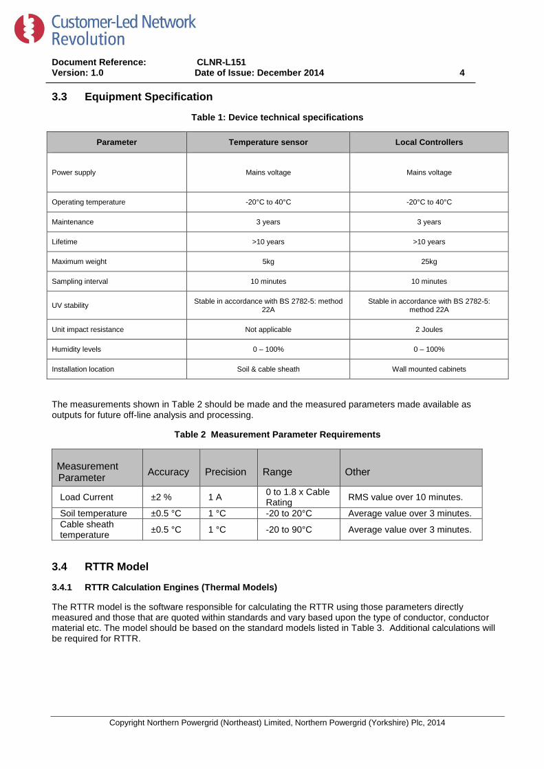
The measurements shown in Table 2 should be made and the measured parameters made available as outputs for future off-line analysis and processing.

Table 2 Measurement Parameter Requirements

Measurement Parameter

Accuracy Precision Range Other

Load Current ±2 % 1 A 0 to 1.8 x Cable Rating

RMS value over 10 minutes.

Soil temperature ±0.5 °C 1 °C -20 to 20°C Average value over 3 minutes.

Cable sheath temperature

±0.5 °C 1 °C -20 to 90°C Average value over 3 minutes.

3.4 RTTR Model

3.4.1 RTTR Calculation Engines (Thermal Models)

The RTTR model is the software responsible for calculating the RTTR using those parameters directly measured and those that are quoted within standards and vary based upon the type of conductor, conductor material etc. The model should be based on the standard models listed in Table 3. Additional calculations will be required for RTTR.

Document Reference: CLNR-L151 Version: 1.0 Date of Issue: December 2014 5

Copyright Northern Powergrid (Northeast) Limited, Northern Powergrid (Yorkshire) Plc, 2014

Table 3: Thermal Models

Thermal Models

IEC 60287

IEC 60853

Parameters that should be directly measured unless otherwise specified by the purchasing Network Operator are listed in Table 4. Additional characteristics are required for modelling purposes; for example type of conductor, formation of cables, conductor material, burial details etc.

Table 4: Time-series parameters

Measured Parameters Comments

Ambient Soil Temperature Must be measured at the same depth as that at which the cable(s) modelled are buried.

3-phase current The whole cable situation shall be considered when designing RTTR UGC systems so that the loading and

construction of all physically relevant circuits is measured and available to the model.

Cable Sheath Current Where practical cable sheath current shall be directly measured. Sheath current shall be calculated where

measurement is not feasible.

Table 5: Static Parameters

Site specific Parameters (all cable types)

Cable Type (Standard Cable conforms to)

Conductor Type and Size

Insulation Type

Burial Depth

Cable Configuration

Soil Thermal Resistivity

Spacing between Single Core cables

Rating type (static, cyclic, distribution) and parameters (load curve, % emergency load and emergency load duration) required

Table 6: Additional Static Parameters (cables in ducts)

Site specific Parameters (cables in ducts)

Duct Type

Duct internal diameter

Duct Configuration

Spacing between successive ducts

Document Reference: CLNR-L151 Version: 1.0 Date of Issue: December 2014 6

Copyright Northern Powergrid (Northeast) Limited, Northern Powergrid (Yorkshire) Plc, 2014

Table 7: Additional Static Parameters (different cable types)

HV and EHV Polymeric Cables

Screen Area

Sheath type

Bonding Arrangement

LV Three-Core Cables/ Four-Core / Five-Core Cables

Neutral / Earth Wire Material

Sheath type

Spacing between successive ducts

EHV Three-Core Cables

Armour Type

Sheath type

Bonding Arrangement

3.4.2 RTTR Model Outputs

A list of the outputs that the system should be able to send to a remote point is given in Table 8; these may be calculated or measured directly. All output parameters should be time-stamped with an accuracy of ±5 seconds and a precision of ±1 second. All time parameters are to be accepted and output in UTC. An option to convert to configurable local time zones for user interaction may be provided. Where additional outputs are available these should be specified by manufacturers. Health indicators should be provided. RTTR settings should be configurable, including:-

• Changes in network configurations, for example a normally open-point is closed; • Changes in maximum and minimum ratings, types of component; • Change of settings – manufacturers should list the settings that are configurable.

Table 8: RTTR model outputs

Outputs

Time-Limited Capacity for 1, 3, 6, 12 hours

Time present load can be sustained under present conditions

Health Alerts

3.4.3 RTTR Model Features

Because of the considerable thermal mass of underground cable systems (especially the direct-buried systems

common in the UK), their time constant is large (from 30 minutes to tens of hours) compared to load variations

they experience. As a result, time-limited overload ratings are already widely used for underground cables via

Document Reference: CLNR-L151 Version: 1.0 Date of Issue: December 2014 7

Copyright Northern Powergrid (Northeast) Limited, Northern Powergrid (Yorkshire) Plc, 2014

pre-computed load curves. A cyclic rating will overload the cable during the peak of the load curve, but allow it

to cool during the low load points so that the conductor temperature limit is never exceeded. Distribution

ratings take this a stage further by based the rating on the increased load experienced post-fault. This load is

both cyclic (because of normal cyclic loading) and time-limited (faults are expected to be fixed within a fixed

number of days). These factors allow a higher normal operating load on the network, without compromising its

ability to maintain supply after a fault.

When recommending a cable RTTR system is important to understand which of these various ratings is

required to be calculated in real time, so that it can be both fairly compared to the correct static rating, and so

that the RTTR is applied safely. This may require the computation of several different ratings from the RTTR

system for different purposes, e.g. a normal load rating which ensures thermal headroom for post-fault

conditions, and a post-fault rating which allows all available capacity to be exploited for a limited period to avoid

taking customers off supply. Some rating conditions require assumptions or predictions to be made about the

future values of the time series parameters (Table 4). Suppliers should state what options are available for

these predictions. It will be advantageous for systems to automatically ‘learn’ the loading of the cables they

model and refine these predictions.

Most cables will run through a range of different ground conditions, and may include more than one cable type

due to jointing along their length. Suppliers should be able to accommodate multiple sets of parameters (as in

Table 4, Table 5, Table 6 and Table 7) for a circuit, and calculate the RTTR of the whole circuit based on the

lowest section rating under present conditions.

One aspect of these different conditions will be the proximity of other power cables which will reduce the rating

of the RTTR circuit due to mutual heating. The RTTR system will need to accept additional sets of parameters

for these adjacent circuits in order to calculate the mutual heating effects and their impact on the rating of the

RTTR circuit. In some circumstances it may be advantageous to take a whole-system approach and determine

RTTR for all circuits running through an area in a combined system which can model mutual heating and

compute advanced effects like post-fault ratings with one of the group of mutually heated cables out of service.

3.5 Communication between System Components

3.5.1 Protocols

All systems should be suitable to communicate with industry standard SCADA protocols; this should be via

direct communication or by using an intermediate device. The preferred protocols are likely to be DNP3 or IEC

61850. In all cases the communications equipment must be compliant with the EMC requirements given in

Appendix 7. The manufacturer will be required to agree the communications protocol and format of data with

purchasing Network Operator.

3.6 Safety Live line working is permitted on UK Distribution Networks, typically up to 33kV although limits do vary. This is

subject to suitable working practices being developed and the appropriate health and safety policies. Potential

suppliers should comply with their statutory obligations under the Construction (Design and Management)

Regulations 2007, in particular to avoid foreseeable risks to those involved in the installation and further use of

the equipment. A list of appropriate BS, ENA standards and guidelines are given at the end of this document;

these should be adhered and conformed to. Manufacturers should provide example procedures, method

statements and risk assessments to the Network Operator to facilitate the assessment of safe installation

procedures, for both live and dead installations.

Document Reference: CLNR-L151 Version: 1.0 Date of Issue: December 2014 8

Copyright Northern Powergrid (Northeast) Limited, Northern Powergrid (Yorkshire) Plc, 2014

4 References The products described within this recommendation should comply with the latest versions of the relevant International Standards, British Standard Specifications and all relevant Energy Network Association Technical Specifications (ENATS) current at the time of supply.

4.1 External Documentation

Reference Title

ASTM D5334 - 08 Standard Test Method for Determination of Thermal Conductivity of Soil and Soft Rock by Thermal Needle Probe Procedure

BS 2782:method 552A Methods of testing plastics — Optical and colour properties, weathering — Determination of changes in colour and variations in properties after exposure to

daylight under glass, natural weathering or laboratory light sources

BS EN 60529 Specification for degrees of protection provided by enclosures (IP code)

BS EN 60801-2 : 1993 Electromagnetic compatibility for industrial-process measurement and control equipment. Electrostatic discharge requirements

BS EN 61000 Electromagnetic compatibility

BS EN 61000-4-2 :2009 Electrostatic Discharge Immunity test

BS EN 61000-4-3 :2006 +A2:2010 Testing and measurement techniques. Radiated, radio-frequency, electromagnetic field immunity test

BS EN 61000-4-4:2004-07 Testing and measurement techniques - Electrical fast transient/burst immunity test

BS EN 61000-6-2 :2005 Generic standards - Immunity standards for industrial environments.

BS EN 61000-6-3:2007 +A1:2011 Generic standards - Emission standards for residential, commercial and light-industrial environments

BS IEC 60287 Electric cables. Calculation of the current rating.

BS IEC 60751 Industrial platinum resistance thermometers and platinum temperature sensors

BS IEC 60853 Calculation of the cyclic and emergency current rating of cables. Cyclic rating factor for cables of all voltages, with partial drying of the soil

ENA ER P17, 1976 Current Rating Guide for Distribution Cables

IETF RFC 5905 Network Time Protocol Version 4: Protocol and Algorithms Specification

IETF RFC 5906 Network Time Protocol Version 4: Autokey Specification

IETF RFC 5907 Definitions of Managed Objects for Network Time Protocol Version 4

The supplier should provide with the tender, full technical details of the equipment offered and shall indicate any divergence from these standards or specification

Document Reference: CLNR-L151 Version: 1.0 Date of Issue: December 2014 9

Copyright Northern Powergrid (Northeast) Limited, Northern Powergrid (Yorkshire) Plc, 2014

5 Definitions

Term Definition

BS British Standard

CT Current Transformer

DNO Distribution Network Operator

DTS Distributed Temperature Sensing

EMC Electromagnetic Compatibility

ENA Energy Networks Association

GPRS General Packet Radio Services (GPRS) is a packet-based wireless communication service that provides data rates from 56 up to 114 Kbps and continuous connection to

the Internet for mobile phone and computer users. GPRS is based on Global System for Mobile (GSM) communication system.

IEC International Electrotechnical Commission

IETF Internet Engineering Task Force, a standards organisation for the Internet

IP Ingress Protection

LAN Local Area Network

NA Not Applicable

NTP Network Time Protocol (see IETF RFC 5905)

RTTR Real-Time Thermal Rating

UTC Universal Coordinated Time, the international time standard with no seasonal changes to which all other time zones are referenced (aligned to GMT in UK winter).

UV Ultraviolet

WAN Wide Area Network

Document Reference: CLNR-L151 Version: 1.0 Date of Issue: December 2014 10

Copyright Northern Powergrid (Northeast) Limited, Northern Powergrid (Yorkshire) Plc, 2014

Appendix 1 – Schedule of Suppliers Technical Data

The following Technical schedules must be completed by suppliers

Temperature Sensor compliance with Equipment Specification (Table 1)

Parameter Compliance with, (Y / N – comment)

Power supply

Operating temperature

Maintenance

Lifetime

Maximum weight

Sampling interval

UV stability

Unit impact resistance

Humidity levels

Installation location

Local Controller compliance with Equipment Specification (Table 1)

Parameter Compliance with, (Y / N – comment)

Power supply

Operating temperature

Maintenance

Lifetime

Maximum weight

Sampling interval

UV stability

Unit impact resistance

Humidity levels

Installation location

Document Reference: CLNR-L151 Version: 1.0 Date of Issue: December 2014 11

Copyright Northern Powergrid (Northeast) Limited, Northern Powergrid (Yorkshire) Plc, 2014

Compliance with Thermal Models (Table 3)

Thermal Models Compliance with, (Y / N – comment)

IEC 60287

IEC 60853

Compliance with measured time-series parameters (Table 4)

Measured Parameters Compliance with, Y / N - comment

Ambient Soil Temperature

3-phase current

Cable Sheath Current

Compliance with recorded static parameters (Table 5)

Site specific Parameters (all cable types)

Cable Type (Standard Cable conforms to)

Conductor Type and Size

Insulation Type

Burial Depth

Cable Configuration

Soil Thermal Resistivity

Spacing between Single Core cables

Compliance with additional Static Parameters for cables in ducts (Table 6)

Site specific Parameters (cables in ducts)

Duct Type

Duct internal diameter

Duct Configuration

Spacing between successive ducts

Document Reference: CLNR-L151 Version: 1.0 Date of Issue: December 2014 12

Copyright Northern Powergrid (Northeast) Limited, Northern Powergrid (Yorkshire) Plc, 2014

Compliance with additional Static Parameters for different cable types (Table 7)

HV and EHV Polymeric Cables

Screen Area

Sheath type

Bonding Arrangement

LV Three-Core Cables/ Four-Core / Five-Core Cables

Neutral / Earth Wire Material

Sheath type

Spacing between successive ducts

EHV Three-Core Cables

Armour Type

Sheath type

Bonding Arrangement

Compliance with RTTR Outputs (Table 8)

Output Compliance with, (Y / N – comment)

Peak Capacity for 1, 3, 6, 12 hours

Time existing load can be carried under present conditions

Health Alerts

Document Reference: CLNR-L151 Version: 1.0 Date of Issue: December 2014 13

Copyright Northern Powergrid (Northeast) Limited, Northern Powergrid (Yorkshire) Plc, 2014

Appendix 2 – Self Certification Conformance Declaration

Supplier/Product Technical Compliance Grid (to be completed by the supplier for each variant offered).

The measuring devices, local controllers and RTTR calculation engine shall comply with the latest issues of the IEC’s and British Standards quoted within this

specification.

Key elements from the above standards and this specification have been quoted to amplify and/or clarify the requirements of those Standards.

This check sheet identifies the particular clauses of the aforementioned Standards relevant to Underground Cable RTTR systems.

The manufacturer shall declare conformance or otherwise, clause by clause, using the following levels of conformance declaration codes for each conductor.

Conformance declaration codes:

N/A = Clause is not applicable/ appropriate to the product

Cs1 = The product conforms fully with the requirements of this clause

Cs2 = The product conforms partially with the requirements of this clause

Cs3 = The product does not conform to the requirements of this clause

Cs4 = The product does not currently conform to the requirements of this clause, but the

manufacturer proposes to modify and test the product in order to conform.

Note:

Separate Self Certification Conformance Declaration sheets shall be completed

For each product being offered.

Manufacturer:

Product Reference:

Name: Signature: Date:

Instructions for completion

• When Cs1 code is entered no remark is necessary

• When any other code is entered the reason for non-conformance shall be entered

• Prefix each remark with the relevant ‘BS EN’ or ‘ENATS’ as appropriate

Document Reference: CLNR-L151 Version: 1.0 Date of Issue: December 2014 14

Copyright Northern Powergrid (Northeast) Limited, Northern Powergrid (Yorkshire) Plc, 2014

Specific requirements within this specification

Clause/Sub-clause Requirements Conformance Code Remarks

Table 1 Compliance with equipment specifications

Table 2 Compliance with one or more specified thermal model(s)

Table 3 Compliance with time-series parameters

Table 4 Compliance with static parameters dependent parameters

Table 5 Compliance with additional static parameters for cables in ducts

Table 6 Compliance with additional static parameters for varying cable types

Table 7 Compliance with RTTR model outputs

Document Reference: CLNR-L151 Version: 1.0 Date of Issue: December 2014 15

Copyright Northern Powergrid (Northeast) Limited, Northern Powergrid (Yorkshire) Plc, 2014

Appendix 3 – Addendum to Supplier Requirements

Please indicate Packaging/delivery information

Details of how this product will be packaged and delivered shall be provided.

Please indicate dimensions of RTTR system components

Details of the individual RTTR system component dimensions shall be provided.

Please indicate options for location of the calculation engine

Details of how the calculation engine software can be hosted.

Project specific requirements

Any project specific requirements will be provided by the purchasing Network Operator for inclusion in this appendix.

Document Reference: CLNR-L151 Version: 1.0 Date of Issue: December 2014 16

Copyright Northern Powergrid (Northeast) Limited, Northern Powergrid (Yorkshire) Plc, 2014

Appendix 4 - Pre-commission testing, Routine Inspection and Maintenance requirements

Suppliers shall provide details of any recommended pre-commission testing or installation requirements.

Additionally suppliers shall also provide information regarding any periodic inspection or maintenance

requirements to be undertaken during the lifetime of their product.

Document Reference: CLNR-L151 Version: 1.0 Date of Issue: December 2014 17

Copyright Northern Powergrid (Northeast) Limited, Northern Powergrid (Yorkshire) Plc, 2014

Appendix 5 – Electromagnetic Compatibility

Electromagnetic Compatibility Tests for equipment

All equipment shall be compatible with the following generic EMC standards:

• BS EN 61000-6-3: 2007 - Generic Emissions standard

• BS EN 61000-6-2: 2005 - Generic Immunity standard

• BS EN 61000-4-2: 1995 - Electrostatic discharge immunity Test ((Requirement Air 8kV, Contact 4kV)

• BS EN 61000-4-3: 2006 Radiated radio Frequency, Electromagnetic Field Immunity. (Requirement

80MHz-1GHz @ 10V/m)

• BS EN 61000-4-6: 2007 Immunity to conducted disturbances induced by radio frequency fields

(Requirement 150kHz - 80MHz @ 10V/m)

• BS EN 61000-4-4: 2004 Electrical Fast Transient/Bursts Immunity (Requirements +/- 1kV).

Document Reference: CLNR-L151 Version: 1.0 Date of Issue: December 2014 18

Copyright Northern Powergrid (Northeast) Limited, Northern Powergrid (Yorkshire) Plc, 2014

Appendix 6 - Technical Information Check List The following information shall be provided by the supplier for technical review by the purchasing Network Operator. Additional information shall be provided if requested.

Requirement Provided (Y/N)

Appendix 1 – Completed technical schedules Appendix 2 – Completed self-certification conformance declaration Appendix 4 – Inspection and testing recommendations Appendix 5 – Electromagnetic compatibility Type test evidence Routine test plan (example) Packaging/delivery information


Recommended