Technologies and Economics of Turbine Inlet Cooling Applications in Cogeneration Dharam V. Punwani Avalon Consulting, Inc. Presented at The Midwest Cogeneration Association and The Illinois Water Works Association Conference Countryside, IL May 6, 2008
Transcript
Technologies and Economics of Turbine Inlet Cooling Applications in Cogeneration
Dharam V. PunwaniAvalon Consulting, Inc.
Presented atThe Midwest Cogeneration Association and
The Illinois Water Works Association Conference
Countryside, ILMay 6, 2008
Presentation Outline
• Introduction
• Effects of Ambient Air Temperature on the Performance of Combustion Turbines
• What is Turbine Inlet Cooling (TIC)?
• Benefits of TIC
• TIC Technologies
• Economics of TIC Applications in Cogeneration
• TIC Applications in Cogeneration
• Conclusions
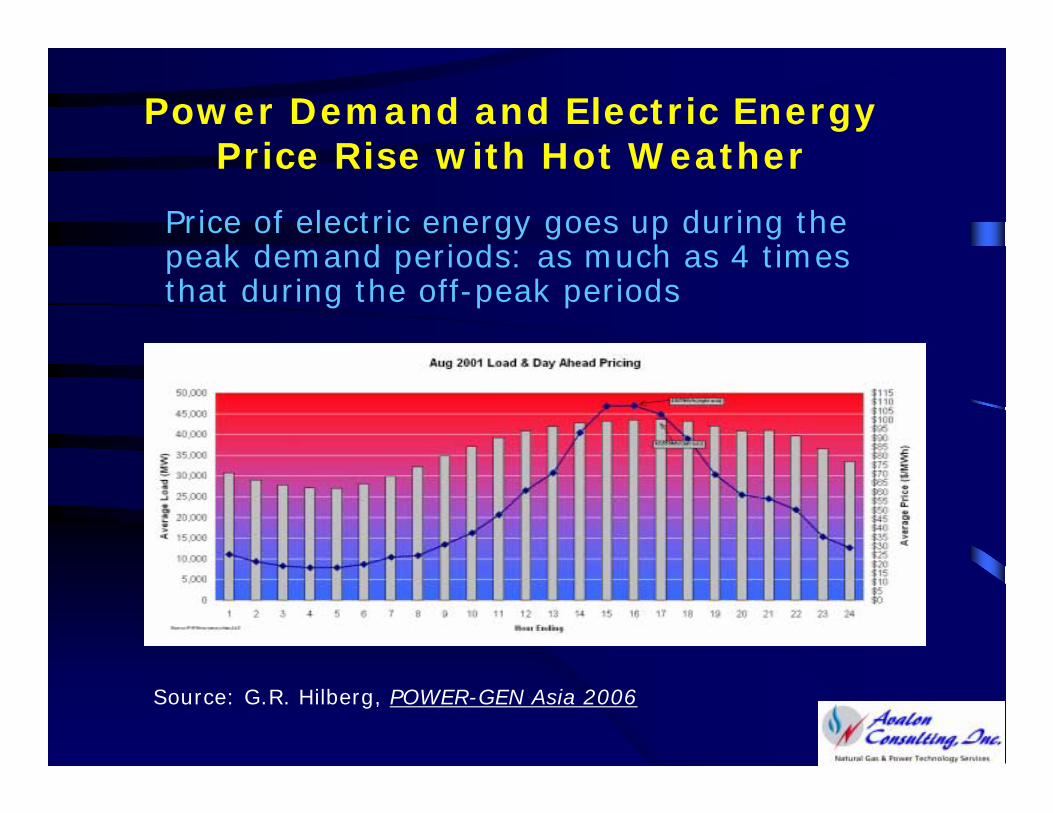
Power Demand and Electric Energy Price Rise with Hot Weather
Price of electric energy goes up during the peak demand periods: as much as 4 times that during the off-peak periods
Source: G.R. Hilberg, POWER-GEN Asia 2006
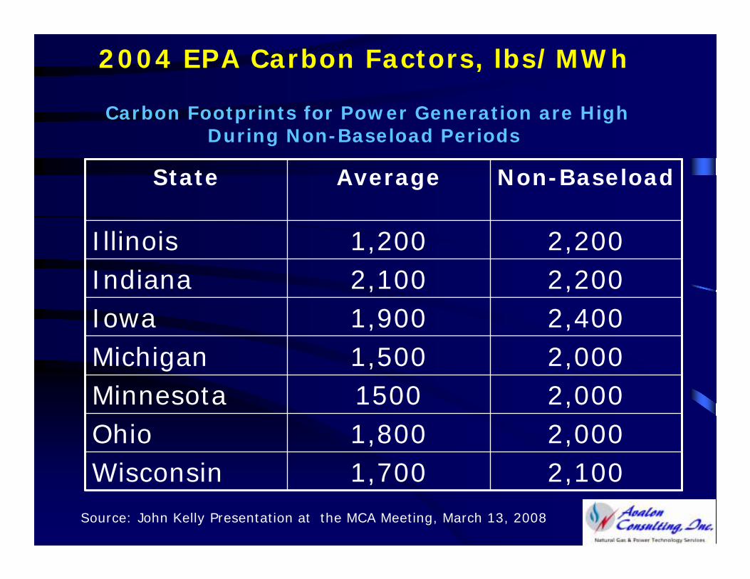
2004 EPA Carbon Factors, lbs/MWh
Carbon Footprints for Power Generation are High During Non-Baseload Periods
Source: John Kelly Presentation at the MCA Meeting, March 13, 2008
Carbon Footprint Reduction Efforts
• Many organizations, including power producers, are trying various options for reducing the carbon footprint
• Most such options come at premium prices, which ratepayers eventually pay.
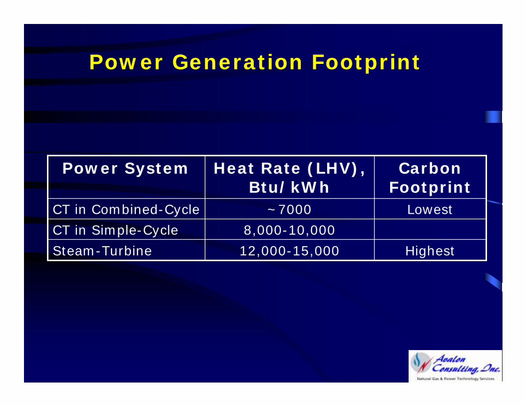
Power Generation Footprint
Highest12,000-15,000Steam-Turbine
8,000-10,000CT in Simple-Cycle
Lowest~7000CT in Combined-Cycle
Carbon Footprint
Heat Rate (LHV), Btu/kWh
Power System
CT-Based Characteristic
Increase in Ambient Air Temperature Causes a Triple Whammy:
• Reduces Power Output
• Increases Heat Rate
• Reduces Thermal Energy in the CT Exhaust Gases
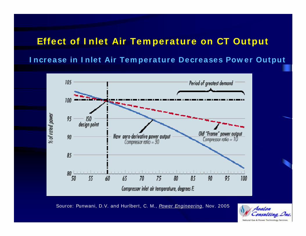
Effect of Inlet Air Temperature on CT Output
Increase in Inlet Air Temperature Decreases Power Output
Source: Punwani, D.V. and Hurlbert, C. M., Power Engineering, Nov. 2005
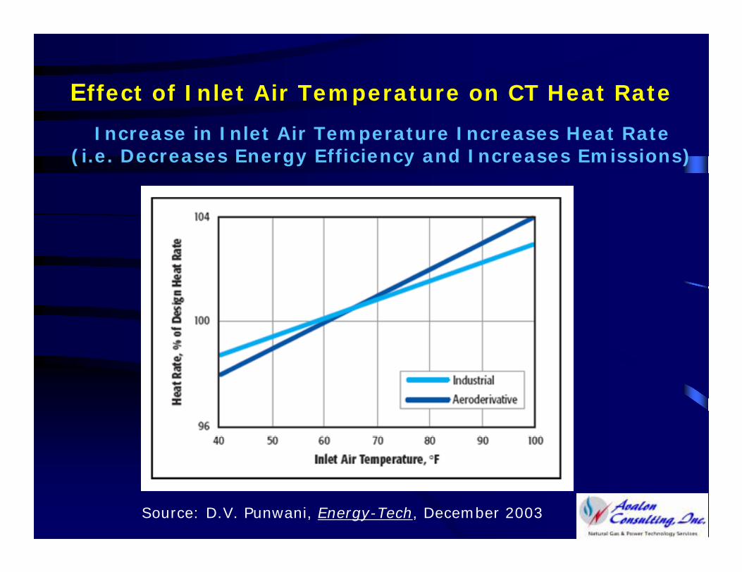
Effect of Inlet Air Temperature on CT Heat Rate
Increase in Inlet Air Temperature Increases Heat Rate (i.e. Decreases Energy Efficiency and Increases Emissions)
Source: D.V. Punwani, Energy-Tech, December 2003
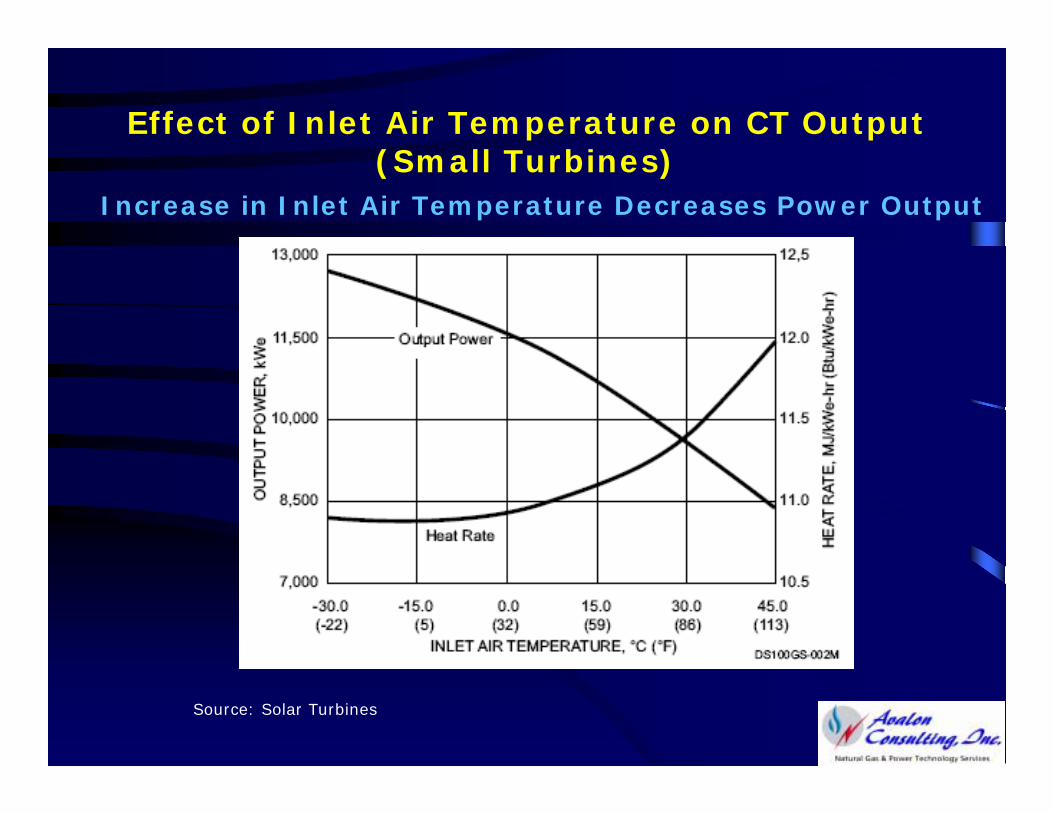
Effect of Inlet Air Temperature on CT Output (Small Turbines)
Increase in Inlet Air Temperature Decreases Power Output
Source: Solar Turbines
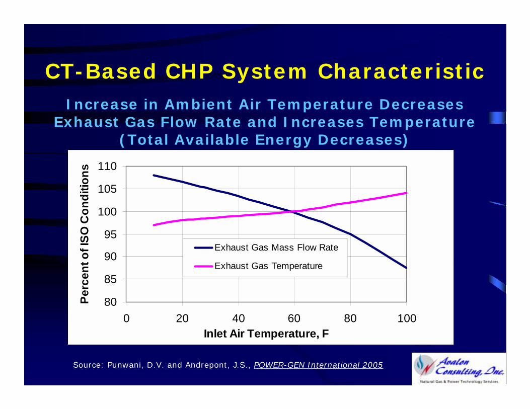
CT-Based CHP System CharacteristicIncrease in Ambient Air Temperature Decreases
Exhaust Gas Flow Rate and Increases Temperature (Total Available Energy Decreases)
80
85
90
95
100
105
110
0 20 40 60 80 100Inlet Air Temperature, F
Perc
ent o
f ISO
Con
ditio
ns
Exhaust Gas Mass Flow Rate
Exhaust Gas Temperature
Source: Punwani, D.V. and Andrepont, J.S., POWER-GEN International 2005
Economic Impacts of Increase in Ambient Temperature on CT-Based Systems
• Increases the cost of buying power and thermal energy (to make up for the lost CT output), if the Cogen owner is using its output for meeting its own needs, or
• Reduces revenue potential from the sale of power and thermal energy, if the cogen owner is selling these energies to others
Environmental Impacts of Increase in Ambient Temperature on CT-Based Systems
• Increases the carbon footprint for power generation at the generation facility
• Increases the carbon footprint of power generation for the grid system connected to the generation facility (because somewhere a less efficient system has to be brought online to meet the demand to prevent power outage)
Why Cool to the turbine inlet air?
Overcome all three detrimental effects of increase in inlet air temperature on the CT performance:
1. Decrease in power generation capacity
2. Increase in Heat Rate
3. Decrease in enthalpy of the CT exhaust gases
TIC Economic Benefits
•• Increases CT output (Increases CT output (MWhMWh and thermal energy) and and thermal energy) and thus, saves cost of buying or reduces revenue for selling thus, saves cost of buying or reduces revenue for selling these energies during onthese energies during on--peak demand periods when peak demand periods when electric energy demand and price are highestelectric energy demand and price are highest
•• Reduces cost of electric energy generation compared Reduces cost of electric energy generation compared to the less energy efficiency “to the less energy efficiency “peakerspeakers””
•• Requires less investment per unit ($/kW) of the Requires less investment per unit ($/kW) of the increased generation capacity compared to new power increased generation capacity compared to new power plantsplants
TIC Environmental Benefits
Reduced Emissions of GHG and pollutantsReduced Emissions of GHG and pollutants
!! Displaced/eliminated operation (up to 30 % Displaced/eliminated operation (up to 30 % of the CT capacity*) of less efficient and higher of the CT capacity*) of less efficient and higher emission power plantsemission power plants
!! Increased efficiency of fuel utilizationIncreased efficiency of fuel utilization
Reduced Need for Reduced Need for SitingSiting New Generation Capacity New Generation Capacity for Meeting Power Demand During Hot Weatherfor Meeting Power Demand During Hot Weather
____________________________________
* During hot weather* During hot weather
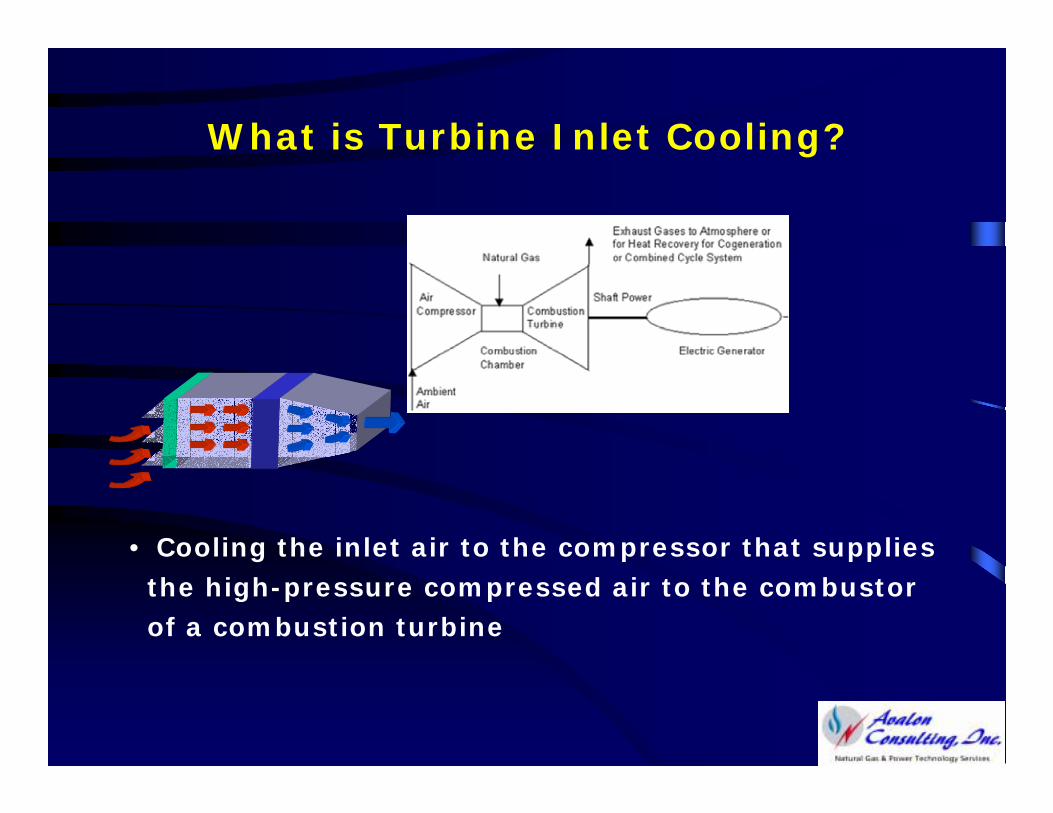
What is Turbine Inlet Cooling?
• Cooling the inlet air to the compressor that supplies the high-pressure compressed air to the combustor of a combustion turbine
Disadvantages of TIC
• Permanent higher CT inlet pressure drop
• Magnitude of inlet pressure drop varies with the cooling technology:
0.1 to 1.0 WC (~0.025 to 0.25% of the CT Output)
• Small drop in CT output capacity even when inlet cooling is not being used
• Additional maintenance cost of the cooling equipment
TIC Commercial Experience
• Over thousand plants are already using one of the TIC technologies
• TIC systems are available from multiple suppliers
TIC Technologies
• Evaporative Cooling
- Wetted Media
- Fogging
• Chillers
- Mechanical (Electric- or Steam-Driven)
- Absorption Chillers
- With Thermal Energy Storage
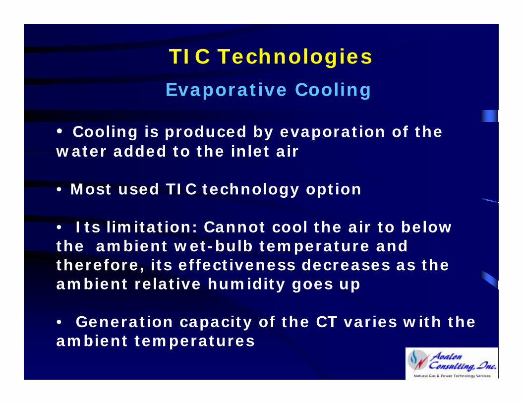
TIC Technologies
Evaporative Cooling
• Cooling is produced by evaporation of the water added to the inlet air
• Most used TIC technology option
• Its limitation: Cannot cool the air to below the ambient wet-bulb temperature and therefore, its effectiveness decreases as the ambient relative humidity goes up
• Generation capacity of the CT varies with the ambient temperatures
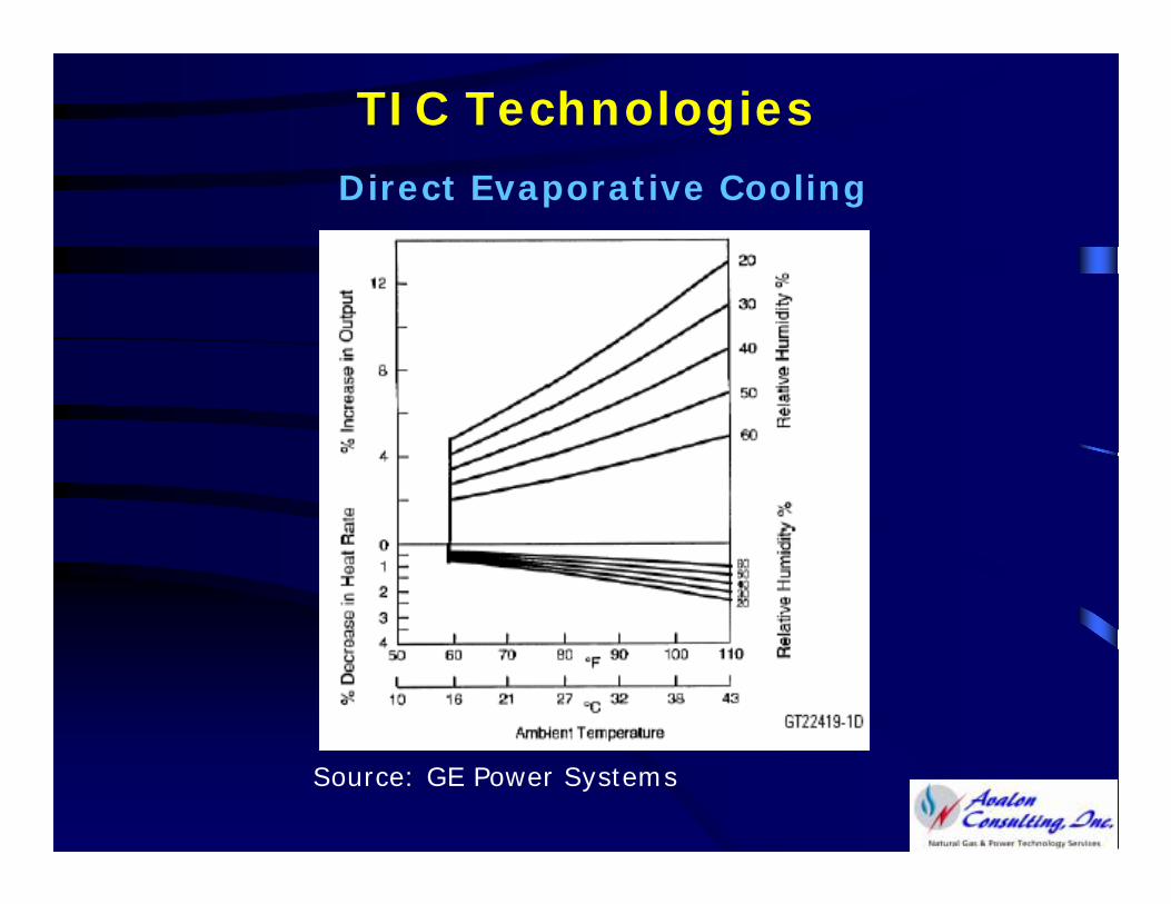
TIC Technologies
Direct Evaporative Cooling
Source: GE Power Systems
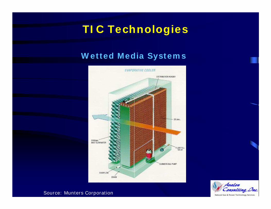
TIC Technologies
Wetted Media Systems
Source: Munters Corporation
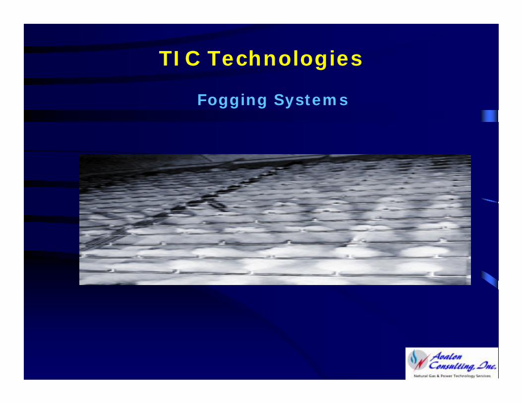
TIC Technologies
Fogging Systems
TIC Technologies
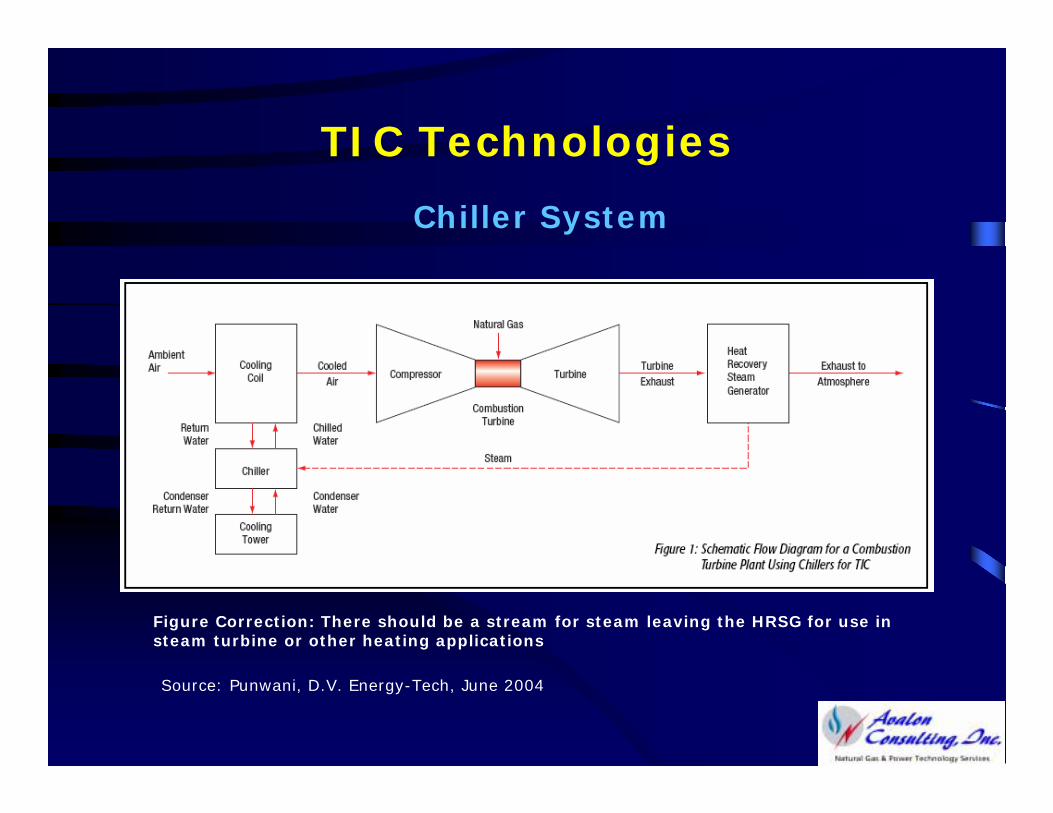
Chiller System
Steam
Source: Punwani, D.V. Energy-Tech, June 2004
Figure Correction: There should be a stream for steam leaving the HRSG for use in steam turbine or other heating applications
TIC Technologies
Chiller Systems
• Cool the air by exchanging heat through a cold fluid produced by a chiller
• Can cool the inlet air to any desired temperature even below the wet-bulb temperature to as low as 42F (Even lower if the ambient air is very dry)
• Can maintain constant CT output irrespective of the ambient temperatures
TIC Technologies
Chiller Systems
• Many types of chillers are applicable and commercially used:
MECHANICAL: Electric-, Steam-Turbine or Engine-Driven
ABSORPTION: Aqua-Ammonia or Lithium Bromide-Water
• With or without thermal energy storage (TES)
TIC Technologies
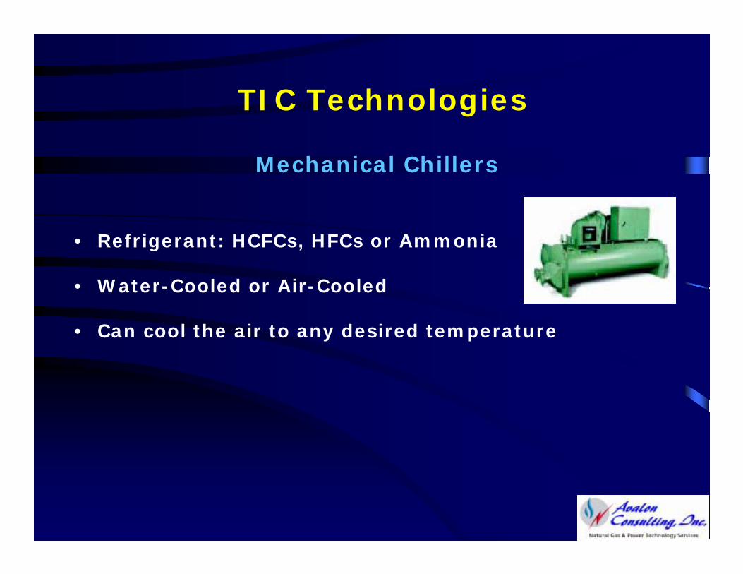
Mechanical Chillers
• Refrigerant: HCFCs, HFCs or Ammonia
• Water-Cooled or Air-Cooled
• Can cool the air to any desired temperature
TIC Technologies
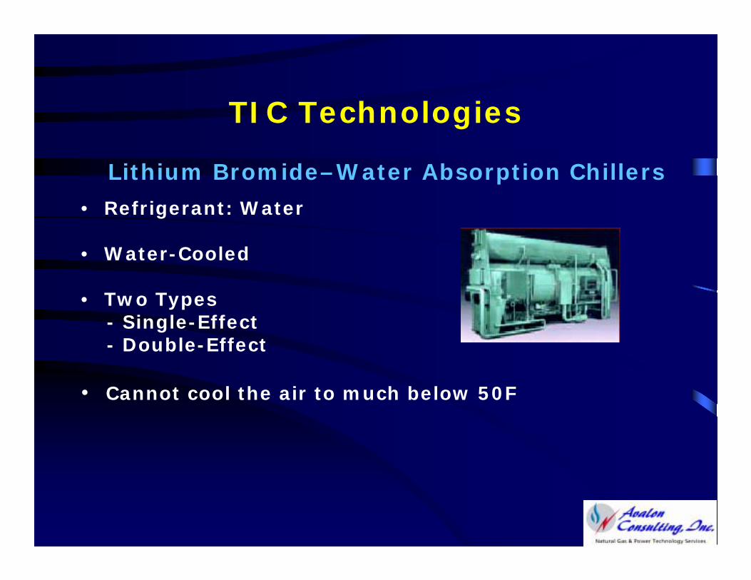
Lithium Bromide–Water Absorption Chillers
• Refrigerant: Water
• Water-Cooled
• Two Types- Single-Effect- Double-Effect
• Cannot cool the air to much below 50F
TIC Technologies
Lithium Bromide–Water Absorption Chillers
Primary Energy Source Options
• Single-Effect- Steam (15 psig): 18lb/h ton- Hot Water (at least 180F)
• Double-Effect- Steam (115 psig): 10lb/ ton- Natural Gas or Exhaust Gases
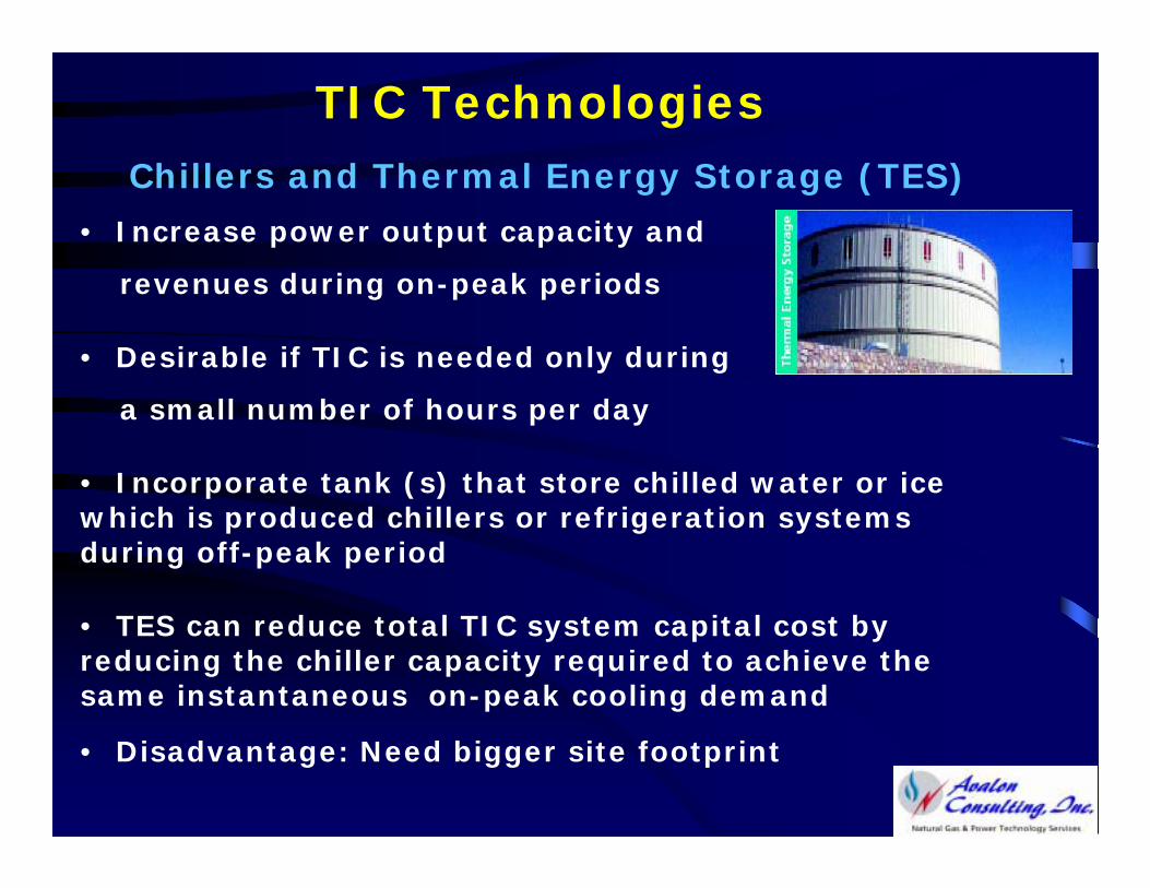
TIC TechnologiesChillers and Thermal Energy Storage (TES)
• Increase power output capacity and
revenues during on-peak periods
• Desirable if TIC is needed only during
a small number of hours per day
• Incorporate tank (s) that store chilled water or ice which is produced chillers or refrigeration systems during off-peak period
• TES can reduce total TIC system capital cost by reducing the chiller capacity required to achieve the same instantaneous on-peak cooling demand
• Disadvantage: Need bigger site footprint
TIC Technologies
Chillers and Thermal Energy Storage (TES)
TES system options:1. Full-Shift: Chillers not operated during on-peak
2. Partial-Shift: Chillers also operated during on-peak to complement the cooling capacity available from the stored chilled water or ice
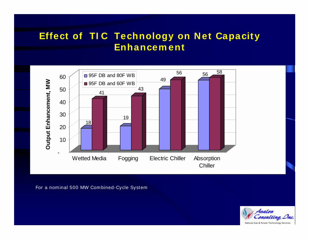
Effect of TIC Technology on Net Capacity Enhancement
For a nominal 500 MW Combined-Cycle System
18
41
19
43
4956 56 58
-
10
20
30
40
50
60
Out
put E
nhan
cem
ent,
MW
Wetted Media Fogging Electric Chiller AbsorptionChiller
95F DB and 80F WB95F DB and 60F WB
TIC Economics
Is TIC Cost Effective?
Depends on many factors, including:
• Weather data for the plant location*
• Market value/price of electric energy
• Cost of fuel
* Chicago area has over 3,360 when temperature is above 59F
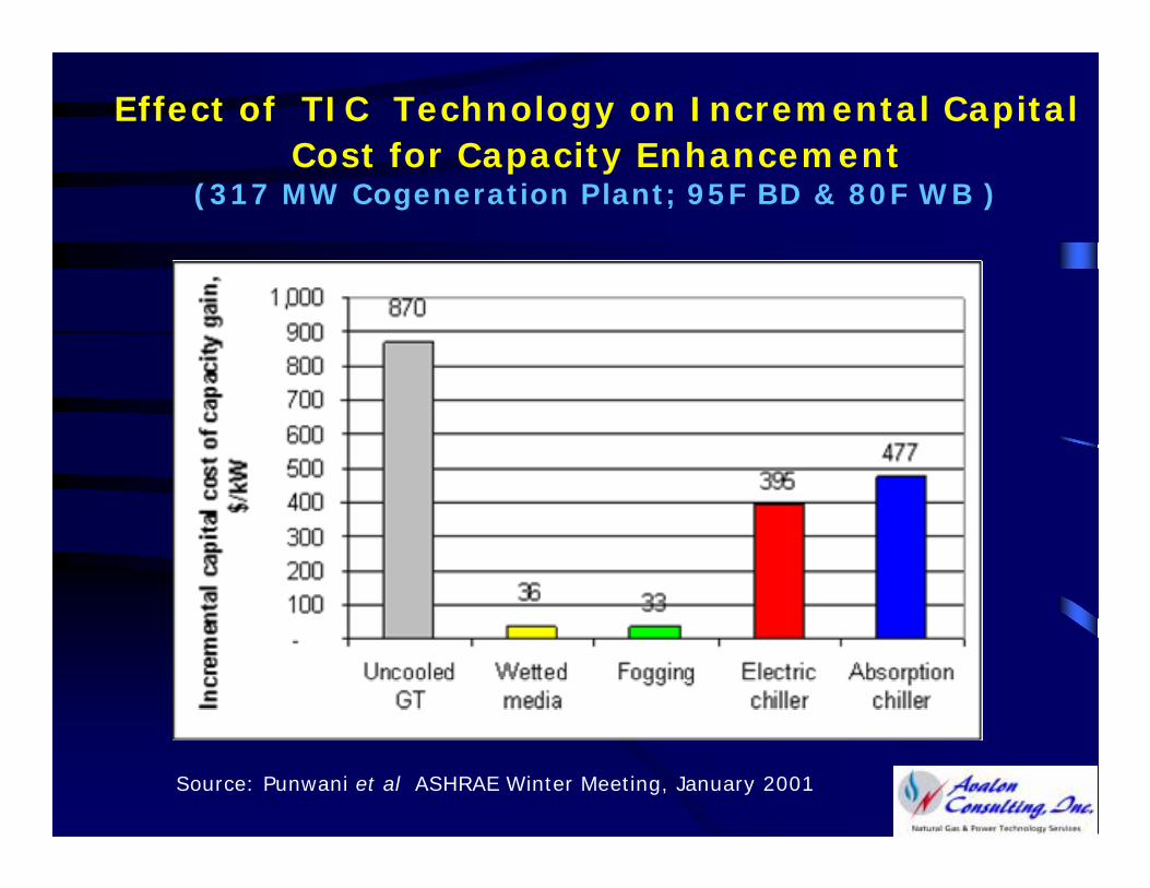
Effect of TIC Technology on Incremental Capital Cost for Capacity Enhancement
(317 MW Cogeneration Plant; 95F BD & 80F WB )
Source: Punwani et al ASHRAE Winter Meeting, January 2001
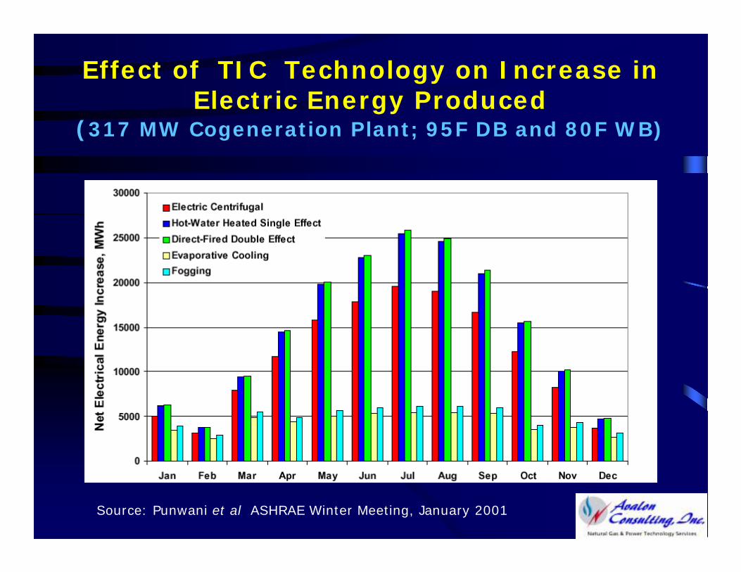
Effect of TIC Technology on Increase in Electric Energy Produced
(317 MW Cogeneration Plant; 95F DB and 80F WB)
Source: Punwani et al ASHRAE Winter Meeting, January 2001
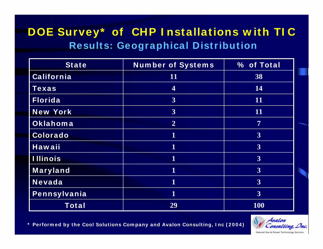
DOE Survey* of CHP Installations with TIC Results: Geographical Distribution
31Pennsylvania
10029Total
31Nevada
31Maryland
31Illinois
31Hawaii
31Colorado
72Oklahoma
113New York
113Florida
144Texas
38 11California
% of TotalNumber of SystemsState
* Performed by the Cool Solutions Company and Avalon Consulting, Inc (2004)
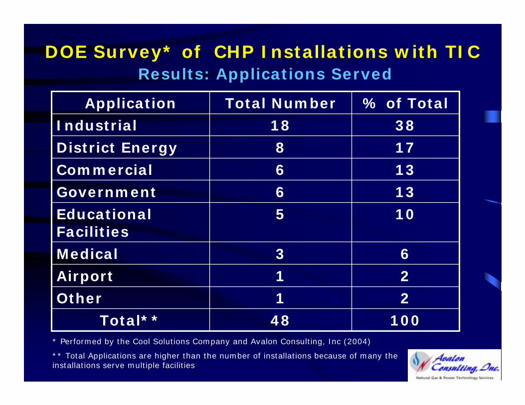
DOE Survey* of CHP Installations with TIC Results: Applications Served
10048Total**
21Other
21Airport
63Medical
105Educational Facilities
136Government
136Commercial
178District Energy
3818Industrial
% of TotalTotal NumberApplication
* Performed by the Cool Solutions Company and Avalon Consulting, Inc (2004)
** Total Applications are higher than the number of installations because of many the installations serve multiple facilities
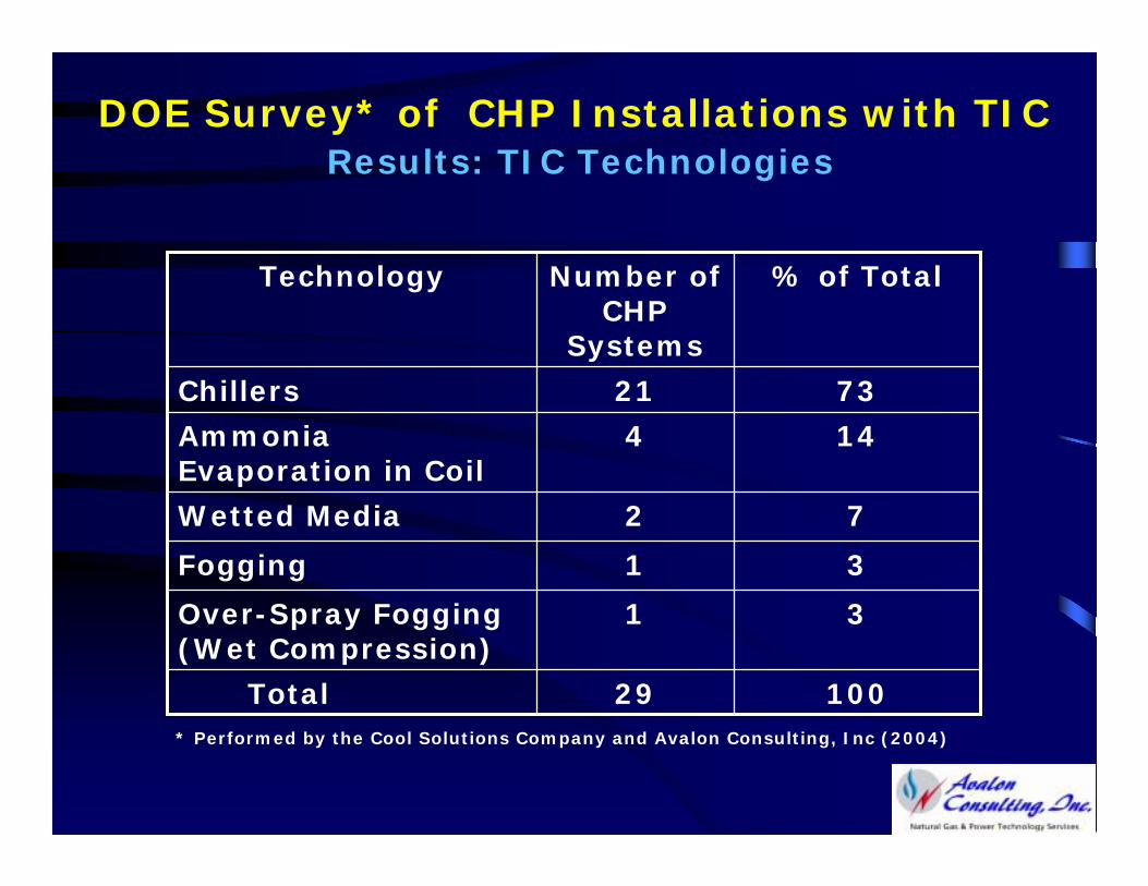
DOE Survey* of CHP Installations with TIC Results: TIC Technologies
72Wetted Media
31Fogging
31Over-Spray Fogging (Wet Compression)
10029Total
144Ammonia Evaporation in Coil
7321Chillers
% of TotalNumber of CHP
Systems
Technology
* Performed by the Cool Solutions Company and Avalon Consulting, Inc (2004)
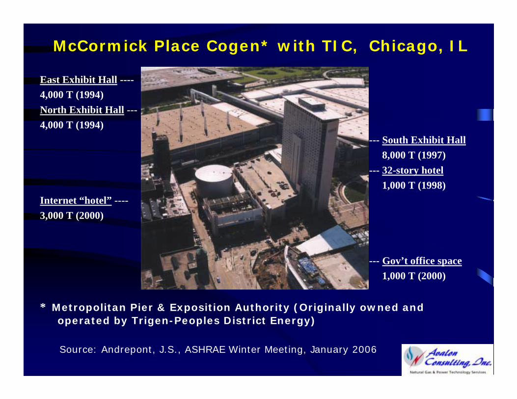
McCormick Place Cogen* with TIC, Chicago, IL
East Exhibit Hall ----4,000 T (1994)North Exhibit Hall ---4,000 T (1994)
--- South Exhibit Hall8,000 T (1997)
--- 32-story hotel1,000 T (1998)
Internet “hotel” ----3,000 T (2000)
--- Gov’t office space1,000 T (2000)
* Metropolitan Pier & Exposition Authority (Originally owned and operated by Trigen-Peoples District Energy)
Source: Andrepont, J.S., ASHRAE Winter Meeting, January 2006
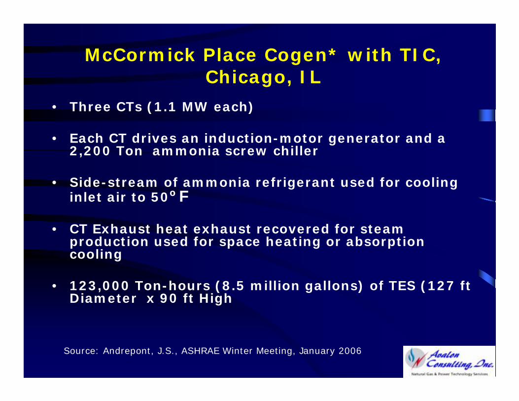
McCormick Place Cogen* with TIC, Chicago, IL
• Three CTs (1.1 MW each)
• Each CT drives an induction-motor generator and a 2,200 Ton ammonia screw chiller
• Side-stream of ammonia refrigerant used for cooling inlet air to 50ºF
• CT Exhaust heat exhaust recovered for steam production used for space heating or absorption cooling
• 123,000 Ton-hours (8.5 million gallons) of TES (127 ft Diameter x 90 ft High
Source: Andrepont, J.S., ASHRAE Winter Meeting, January 2006
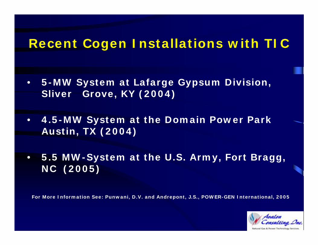
Recent Cogen Installations with TIC
• 5-MW System at Lafarge Gypsum Division, Sliver Grove, KY (2004)
• 4.5-MW System at the Domain Power Park Austin, TX (2004)
• 5.5 MW-System at the U.S. Army, Fort Bragg, NC (2005)
For More Information See: Punwani, D.V. and Andrepont, J.S., POWER-GEN International, 2005
Conclusions
• TIC Improves the Economics of Power Generation
• TIC Reduces Carbon Footprint for Power Generation
• Therefore, TIC is Good the Environment, Rate Payers and Plant Owners