56
DIgSILENT PowerFactory Technical Reference Documentation Two-Winding Transformer (3-Phase) ElmTr2,TypTr2
| Date post: | 13-Apr-2016 |
| Category: |
Documents |
| Upload: | vladimircoello |
| View: | 217 times |
| Download: | 24 times |

DIgSILENT PowerFactoryTechnical Reference Documentation
Two-Winding Transformer (3-Phase)ElmTr2,TypTr2

DIgSILENT GmbH
Heinrich-Hertz-Str. 972810 - Gomaringen
Germany
T: +49 7072 9168 0F: +49 7072 9168 88
http://[email protected]
Version: 15.2Edition: 1
Copyright © 2014, DIgSILENT GmbH. Copyright of this document belongs to DIgSILENT GmbH.No part of this document may be reproduced, copied, or transmitted in any form, by any meanselectronic or mechanical, without the prior written permission of DIgSILENT GmbH.
Two-Winding Transformer (3-Phase) (ElmTr2,TypTr2) 1
Contents
Contents
1 General Description 4
1.1 Model diagrams . . . . . . . . . . . . . . . . . . . . . . . . . . . . . . . . . . . . 4
1.1.1 Positive and negative sequence models . . . . . . . . . . . . . . . . . . . 4
1.1.2 Zero sequence model . . . . . . . . . . . . . . . . . . . . . . . . . . . . . 6
1.2 Tap changer . . . . . . . . . . . . . . . . . . . . . . . . . . . . . . . . . . . . . . . 7
1.3 YN-YN transformer with internal delta winding . . . . . . . . . . . . . . . . . . . . 9
1.3.1 Dependent parameters . . . . . . . . . . . . . . . . . . . . . . . . . . . . 11
1.4 Short-circuit impedance . . . . . . . . . . . . . . . . . . . . . . . . . . . . . . . . 13
1.4.1 Positive sequence impedance . . . . . . . . . . . . . . . . . . . . . . . . . 14
1.4.2 Zero sequence impedance . . . . . . . . . . . . . . . . . . . . . . . . . . 15
2 Load Flow Analysis 17
2.1 Element data . . . . . . . . . . . . . . . . . . . . . . . . . . . . . . . . . . . . . . 17
2.1.1 Measurement report . . . . . . . . . . . . . . . . . . . . . . . . . . . . . . 17
2.1.2 Automatic tap changer control . . . . . . . . . . . . . . . . . . . . . . . . 18
2.2 Type data . . . . . . . . . . . . . . . . . . . . . . . . . . . . . . . . . . . . . . . . 21
2.2.1 Tap changer with two taps . . . . . . . . . . . . . . . . . . . . . . . . . . . 22
3 Short-Circuit Analysis 25
3.1 IEC calculations . . . . . . . . . . . . . . . . . . . . . . . . . . . . . . . . . . . . 25
3.1.1 Element data . . . . . . . . . . . . . . . . . . . . . . . . . . . . . . . . . . 25
3.1.2 Type data . . . . . . . . . . . . . . . . . . . . . . . . . . . . . . . . . . . . 26
4 RMS-Simulation 26
5 EMT-Simulation 26
5.1 Element data . . . . . . . . . . . . . . . . . . . . . . . . . . . . . . . . . . . . . . 26
5.1.1 Stray capacitances . . . . . . . . . . . . . . . . . . . . . . . . . . . . . . . 26
5.2 Type data . . . . . . . . . . . . . . . . . . . . . . . . . . . . . . . . . . . . . . . . 27
5.2.1 Saturation characteristic . . . . . . . . . . . . . . . . . . . . . . . . . . . . 27
5.2.2 Zero sequence magnetising reactance . . . . . . . . . . . . . . . . . . . . 31
Two-Winding Transformer (3-Phase) (ElmTr2,TypTr2) 2

Contents
5.3 Residual flux . . . . . . . . . . . . . . . . . . . . . . . . . . . . . . . . . . . . . . 32
6 Harmonics/Power Quality 33
6.1 K-Factor, Factor-K and FHL . . . . . . . . . . . . . . . . . . . . . . . . . . . . . . 34
6.1.1 K-Factor . . . . . . . . . . . . . . . . . . . . . . . . . . . . . . . . . . . . . 35
6.1.2 Factor-K . . . . . . . . . . . . . . . . . . . . . . . . . . . . . . . . . . . . . 35
6.1.3 FHL . . . . . . . . . . . . . . . . . . . . . . . . . . . . . . . . . . . . . . . 35
6.1.4 Input data . . . . . . . . . . . . . . . . . . . . . . . . . . . . . . . . . . . . 36
6.2 Frequency-dependent zero sequence impedance . . . . . . . . . . . . . . . . . . 36
7 Modelling Details and Application Tips 37
7.1 Reference values . . . . . . . . . . . . . . . . . . . . . . . . . . . . . . . . . . . . 37
7.2 Zero sequence models for common vector groups . . . . . . . . . . . . . . . . . 37
7.2.1 Yd-transformer . . . . . . . . . . . . . . . . . . . . . . . . . . . . . . . . . 37
7.2.2 YNyn/YNy/Yyn-transformer . . . . . . . . . . . . . . . . . . . . . . . . . . 37
7.2.3 Model of YNyn/YNy/Yyn-transformer with closed tertiary delta winding . . 38
7.2.4 Model of YNzn/YNz/Zyn-transformer . . . . . . . . . . . . . . . . . . . . . 39
7.3 Auto transformer model . . . . . . . . . . . . . . . . . . . . . . . . . . . . . . . . 39
8 Input/Output Definitions of Dynamic Models 42
9 Input Parameter Definitions 43
9.1 2-winding transformer type . . . . . . . . . . . . . . . . . . . . . . . . . . . . . . 43
9.2 2-winding transformer element . . . . . . . . . . . . . . . . . . . . . . . . . . . . 48
10 References 53
List of Figures 54
List of Tables 55
Two-Winding Transformer (3-Phase) (ElmTr2,TypTr2) 3
1 General Description
1 General Description
The two-winding transformer model is a highly-detailed model for various kinds of three-phase,two-winding transformers in power systems. It can be used to represent network transformers,block transformers, phase-shifters, auto transformers or MV-voltage regulators.
The 2-winding transformer model in PowerFactory is comprised of the 2-winding transformerelement (ElmTr2), and the 2-winding transformer type (TypTr2). The transformer element allowsinput of data relating to the control of the transformer under steady-state conditions, and thetransformer type allows input of the physical properties of the transformer. For simplicity, thesewill simply be referred to hereafter as the ‘element’ and the ‘type’, respectively.
The first section of this document describes the general model which is valid for all PowerFactorycalculation functions. Other aspects such as saturation or capacitive effects, which are onlyrelevant to specific calculation functions are described in later sections. Section 7 providesuseful tips for special applications of the 2-winding transformer model.
1.1 Model diagrams
1.1.1 Positive and negative sequence models
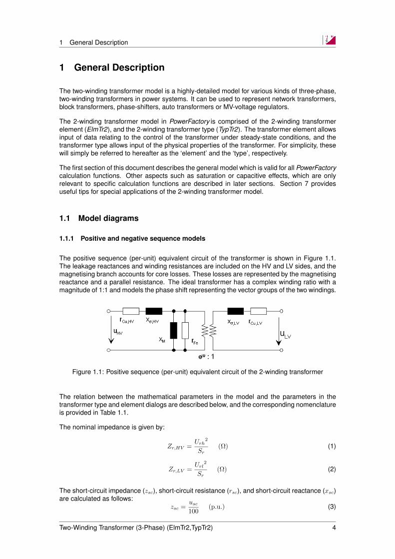
The positive sequence (per-unit) equivalent circuit of the transformer is shown in Figure 1.1.The leakage reactances and winding resistances are included on the HV and LV sides, and themagnetising branch accounts for core losses. These losses are represented by the magnetisingreactance and a parallel resistance. The ideal transformer has a complex winding ratio with amagnitude of 1:1 and models the phase shift representing the vector groups of the two windings.
Figure 1.1: Positive sequence (per-unit) equivalent circuit of the 2-winding transformer
The relation between the mathematical parameters in the model and the parameters in thetransformer type and element dialogs are described below, and the corresponding nomenclatureis provided in Table 1.1.
The nominal impedance is given by:
Zr,HV =Urh
2
Sr(Ω) (1)
Zr,LV =Url
2
Sr(Ω) (2)
The short-circuit impedance (zsc), short-circuit resistance (rsc), and short-circuit reactance (xsc)are calculated as follows:
zsc =usc100
(p.u.) (3)
Two-Winding Transformer (3-Phase) (ElmTr2,TypTr2) 4

1 General Description
rsc =PCu/1000
Sr(p.u.) (4)
xsc =√zsc2 − rsc2 (p.u.) (5)
The leakage impedance (HV and LV sides, respectively) is:
zshv = (rsc · γR,HV,1) + (xsc · γX,HV,1) (p.u.) (6)
zslv = (rsc · (1− γR,LV,1)) + (xsc · (1− γX,LV,1)) (p.u.) (7)
The resistive losses in the windings (HV and LV sides, respectively) are represented by:
rCu,HV = rsc · γR,HV,1 (p.u.) (8)
rCu,LV = rsc · (1− γR,LV,1) (p.u.) (9)
The leakage reactance (HV and LV sides, respectively) is calculated as follows:
xσ,HV = xsc · γX,HV,1 (p.u.) (10)
xσ,LV = xsc · (1− γX,LV,1) (p.u.) (11)
The magnetising impedance is dependent on the no-load current, I0, and is given by:
zM =1
I0/100(p.u.) (12)
The resistive iron losses in the core are calculated as:
rFe =Sr
PFe/1000(p.u.) (13)
and the magnetising reactance is calculated as follows:
xM =1√
1
zM 2− 1
rFe2
(p.u.) (14)
Table 1.1 provides a comprehensive list of the input- and calculation parameters describedabove, and their associated symbols and descriptions.
Two-Winding Transformer (3-Phase) (ElmTr2,TypTr2) 5

1 General Description
Table 1.1: Input- and calculation parameters
Name Symbol Unit DescriptionZr,HV Ω Nominal impedance, HV sideZr,LV Ω Nominal impedance, LV sideutrnh Urh kV Rated voltage on HV sideutrnl Url kV Rated voltage on LV sidestrn Sr MVA Rated powerpcutr PCu kW Copper lossesuktr usc % Relative short-circuit voltagezs zsc p.u. Short-circuit impedancers rsc p.u. Short-circuit resistancexs xsc p.u. Short-circuit reactanceitrdl γX,HV,1 p.u. Proportion of transformer short-circuit reactance on HV
side in the positive sequence systemitrdl lv γX,LV,1 p.u. Proportion of transformer short-circuit reactance on LV
side in the positive sequence systemitrdr γR,HV,1 p.u. Proportion of transformer short-circuit resistance on HV
side in the positive sequence systemitrdr lv γR,LV,1 p.u. Proportion of transformer short-circuit resistance on LV
side in the positive sequence systemrCu,HV p.u. Resistance on HV siderCu,LV p.u. Resistance on LV sidezshv p.u. Leakage impedance on HV sidezshl p.u. Leakage impedance on LV sidexσ,HV p.u. Leakage reactance on HV sidexσ,LV p.u. Leakage reactance on LV sidecurmg I0 % No-load currentpfe PFe kW No-load losseszM p.u. Magnetising impedancexM p.u. Magnetising reactancerFe p.u. Shunt resistance
1.1.2 Zero sequence model
The zero sequence equivalent model of a Yd-transformer including a tap changer at the HVside is shown in Figure 1.2. Transformer models for a variety of configurations are provided inSection 7.2.
Two-Winding Transformer (3-Phase) (ElmTr2,TypTr2) 6

1 General Description
(a)
(b)
Figure 1.2: Zero sequence equivalent circuit of a Yd-transformer with HV side tap changer (a)detailed representation (b) simplified representation
1.2 Tap changer
The tap changer is represented by an additional, ideal transformer connected to either the HVor LV side (see Figure 1.3 and Figure 1.4). For most applications, the winding ratio of thistransformer is real and is defined by the actual tap position (in number of steps) multiplied bythe additional voltage per step.
Figure 1.3: Transformer model with tap changer modelled at the HV side
Two-Winding Transformer (3-Phase) (ElmTr2,TypTr2) 7
1 General Description
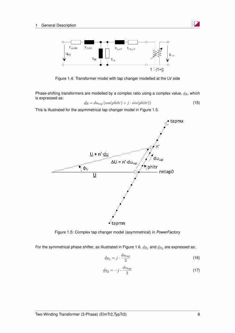
Figure 1.4: Transformer model with tap changer modelled at the LV side
Phase-shifting transformers are modelled by a complex ratio using a complex value, du, whichis expressed as:
du = dutap (cos(phitr) + j · sin(phitr)) (15)
This is illustrated for the asymmetrical tap changer model in Figure 1.5.
Figure 1.5: Complex tap changer model (asymmetrical) in PowerFactory
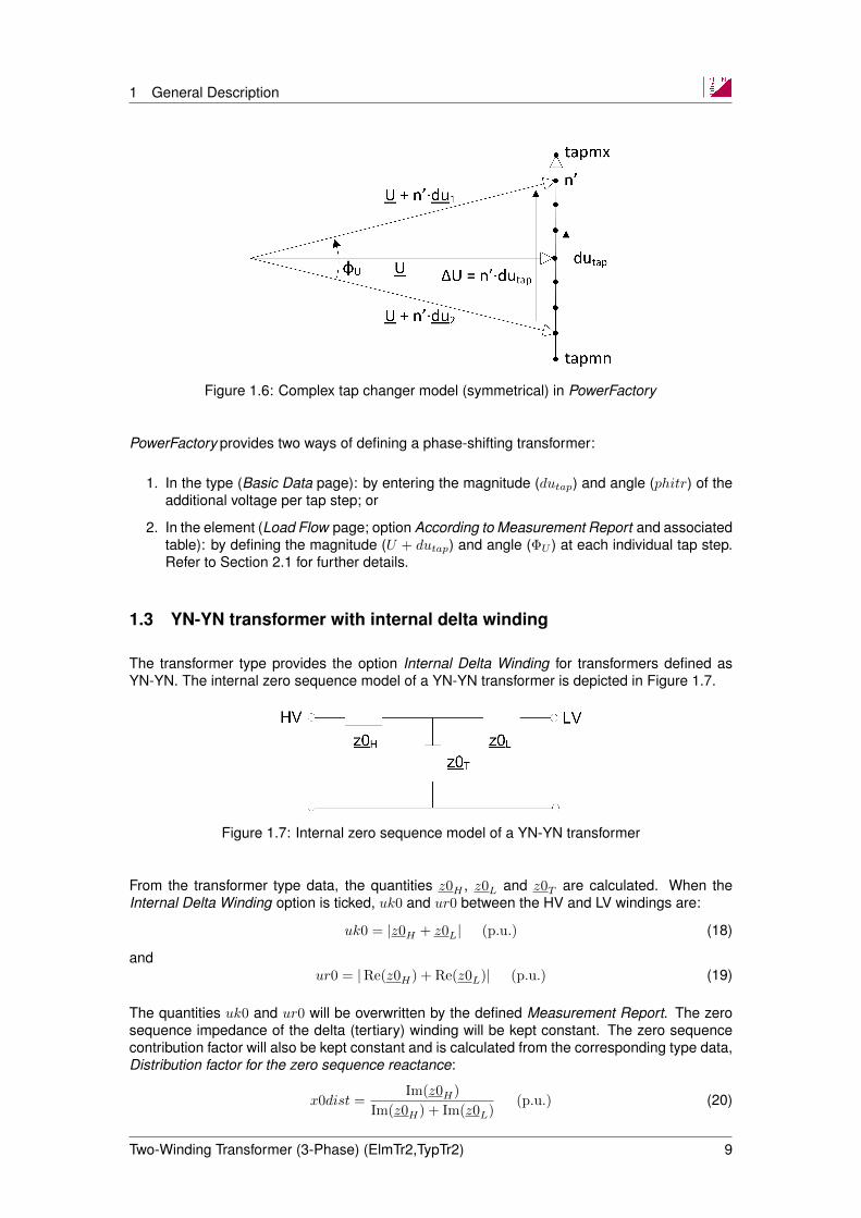
For the symmetrical phase shifter, as illustrated in Figure 1.6, du1 and du2 are expressed as:
du1 = j · dutap2
(16)
du2 = −j · dutap2
(17)
Two-Winding Transformer (3-Phase) (ElmTr2,TypTr2) 8
1 General Description
Figure 1.6: Complex tap changer model (symmetrical) in PowerFactory
PowerFactory provides two ways of defining a phase-shifting transformer:
1. In the type (Basic Data page): by entering the magnitude (dutap) and angle (phitr) of theadditional voltage per tap step; or
2. In the element (Load Flow page; option According to Measurement Report and associatedtable): by defining the magnitude (U + dutap) and angle (ΦU ) at each individual tap step.Refer to Section 2.1 for further details.
1.3 YN-YN transformer with internal delta winding
The transformer type provides the option Internal Delta Winding for transformers defined asYN-YN. The internal zero sequence model of a YN-YN transformer is depicted in Figure 1.7.
Figure 1.7: Internal zero sequence model of a YN-YN transformer
From the transformer type data, the quantities z0H , z0L and z0T are calculated. When theInternal Delta Winding option is ticked, uk0 and ur0 between the HV and LV windings are:
uk0 = |z0H + z0L| (p.u.) (18)
andur0 = |Re(z0H) + Re(z0L)| (p.u.) (19)
The quantities uk0 and ur0 will be overwritten by the defined Measurement Report. The zerosequence impedance of the delta (tertiary) winding will be kept constant. The zero sequencecontribution factor will also be kept constant and is calculated from the corresponding type data,Distribution factor for the zero sequence reactance:
x0dist =Im(z0H)
Im(z0H) + Im(z0L)(p.u.) (20)
Two-Winding Transformer (3-Phase) (ElmTr2,TypTr2) 9

1 General Description
and the distribution factor for the zero sequence resistance:
r0dist =Re(z0H)
Re(z0H) + Re(z0L)(p.u.) (21)
If the sum of the real parts equals zero, r0dist will be set to x0dist. If the sum of the imaginaryparts also equals zero, the distribution factor, x0dist, will be set to 0.5. The zero sequenceimpedance for the HV and LV winding (dependent on the tap position) is then calculated asfollows:
x0hv = x0(tap) · x0dist (p.u.) (22)
x0lv = x0(tap) · (1− x0dist) (p.u.) (23)
andr0hv = r0(tap) · r0dist (p.u.) (24)
r0lv = r0(tap) · (1− r0dist) (p.u.) (25)
with:
x0(tap) =
√uk0(tap)2 − ur0(tap)2
100(p.u.) (26)
r0(tap) =ur0(tap)
100(p.u.) (27)
To determine the complex impedances in Figure 1.7, three measurements are required:
1. The zero sequence current injected at the HV terminal with the LV terminal short-circuited:
z0HLs = ur0hls + j ·√uk02hls − ur02hls (p.u.) (28)
where uk0hls is the HV impedance (in p.u.) and ur0hls is the HV resistance (in p.u.), with the LVterminal short-circuited in both cases.
2. The zero sequence current injected at the HV terminal with the LV terminal open-circuited:
z0HLo = ur0hlo + j ·√uk02hlo − ur02hlo (p.u.) (29)
where uk0hlo is the HV impedance (in p.u.) and ur0hlo is the HV resistance (in p.u.), with the LVterminal open-circuited in both cases.
3. The zero sequence current injected at the LV terminal with the HV terminal open-circuited:
z0LHo = ur0lho + j ·√uk02lho − ur02lho (p.u.) (30)
where uk0lho is the LV impedance (in p.u.) and ur0lho is the LV resistance (in p.u.), with the HVterminal open-circuited in both cases.
For the first measurement:
z0HLs = z0H +z0L · z0Tz0L + z0T
(p.u.) (31)
the second measurement:z0HLo = z0H + z0T (p.u.) (32)
and the third measurement:z0LHo = z0L + z0T (p.u.) (33)
Two-Winding Transformer (3-Phase) (ElmTr2,TypTr2) 10
1 General Description
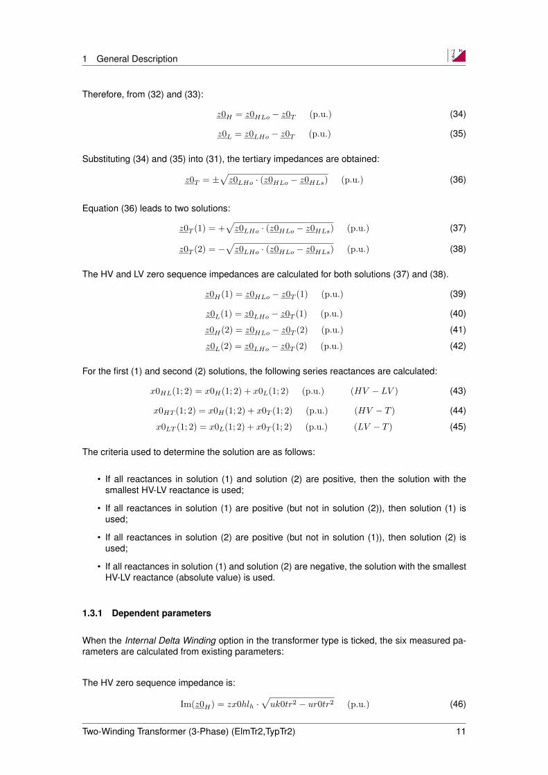
Therefore, from (32) and (33):
z0H = z0HLo − z0T (p.u.) (34)
z0L = z0LHo − z0T (p.u.) (35)
Substituting (34) and (35) into (31), the tertiary impedances are obtained:
z0T = ±√z0LHo · (z0HLo − z0HLs) (p.u.) (36)
Equation (36) leads to two solutions:
z0T (1) = +√z0LHo · (z0HLo − z0HLs) (p.u.) (37)
z0T (2) = −√z0LHo · (z0HLo − z0HLs) (p.u.) (38)
The HV and LV zero sequence impedances are calculated for both solutions (37) and (38).
z0H(1) = z0HLo − z0T (1) (p.u.) (39)
z0L(1) = z0LHo − z0T (1) (p.u.) (40)
z0H(2) = z0HLo − z0T (2) (p.u.) (41)
z0L(2) = z0LHo − z0T (2) (p.u.) (42)
For the first (1) and second (2) solutions, the following series reactances are calculated:
x0HL(1; 2) = x0H(1; 2) + x0L(1; 2) (p.u.) (HV − LV ) (43)
x0HT (1; 2) = x0H(1; 2) + x0T (1; 2) (p.u.) (HV − T ) (44)
x0LT (1; 2) = x0L(1; 2) + x0T (1; 2) (p.u.) (LV − T ) (45)
The criteria used to determine the solution are as follows:
• If all reactances in solution (1) and solution (2) are positive, then the solution with thesmallest HV-LV reactance is used;
• If all reactances in solution (1) are positive (but not in solution (2)), then solution (1) isused;
• If all reactances in solution (2) are positive (but not in solution (1)), then solution (2) isused;
• If all reactances in solution (1) and solution (2) are negative, the solution with the smallestHV-LV reactance (absolute value) is used.
1.3.1 Dependent parameters
When the Internal Delta Winding option in the transformer type is ticked, the six measured pa-rameters are calculated from existing parameters:
The HV zero sequence impedance is:
Im(z0H) = zx0hlh ·√uk0tr2 − ur0tr2 (p.u.) (46)
Two-Winding Transformer (3-Phase) (ElmTr2,TypTr2) 11
1 General Description
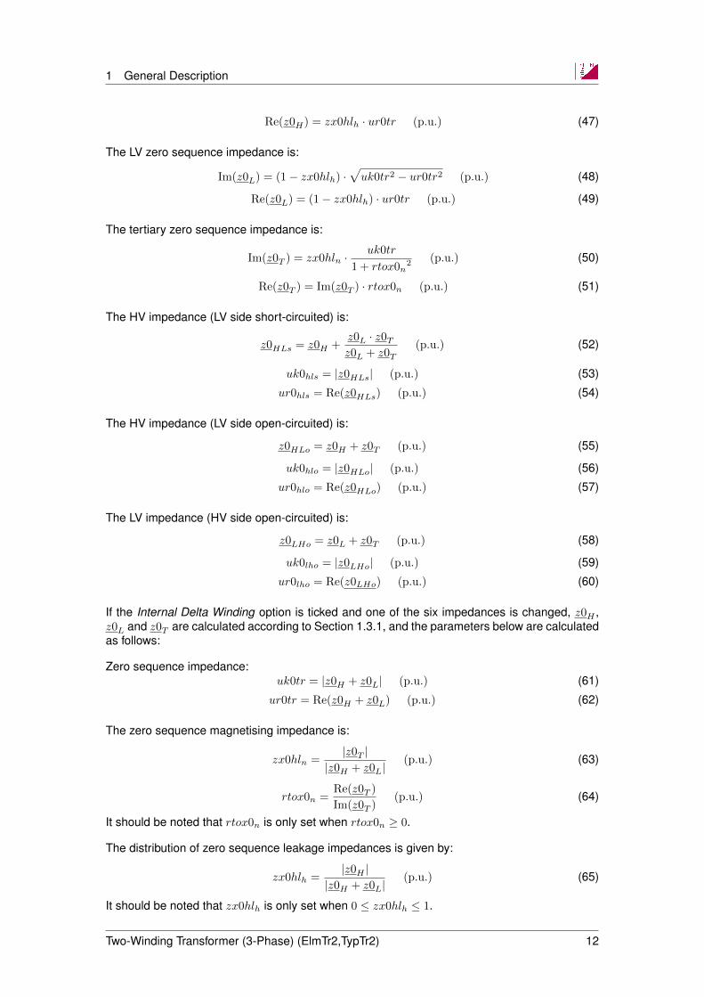
Re(z0H) = zx0hlh · ur0tr (p.u.) (47)
The LV zero sequence impedance is:
Im(z0L) = (1− zx0hlh) ·√uk0tr2 − ur0tr2 (p.u.) (48)
Re(z0L) = (1− zx0hlh) · ur0tr (p.u.) (49)
The tertiary zero sequence impedance is:
Im(z0T ) = zx0hln ·uk0tr
1 + rtox0n2 (p.u.) (50)
Re(z0T ) = Im(z0T ) · rtox0n (p.u.) (51)
The HV impedance (LV side short-circuited) is:
z0HLs = z0H +z0L · z0Tz0L + z0T
(p.u.) (52)
uk0hls = |z0HLs| (p.u.) (53)
ur0hls = Re(z0HLs) (p.u.) (54)
The HV impedance (LV side open-circuited) is:
z0HLo = z0H + z0T (p.u.) (55)
uk0hlo = |z0HLo| (p.u.) (56)
ur0hlo = Re(z0HLo) (p.u.) (57)
The LV impedance (HV side open-circuited) is:
z0LHo = z0L + z0T (p.u.) (58)
uk0lho = |z0LHo| (p.u.) (59)
ur0lho = Re(z0LHo) (p.u.) (60)
If the Internal Delta Winding option is ticked and one of the six impedances is changed, z0H ,z0L and z0T are calculated according to Section 1.3.1, and the parameters below are calculatedas follows:
Zero sequence impedance:uk0tr = |z0H + z0L| (p.u.) (61)
ur0tr = Re(z0H + z0L) (p.u.) (62)
The zero sequence magnetising impedance is:
zx0hln =|z0T |
|z0H + z0L|(p.u.) (63)
rtox0n =Re(z0T )
Im(z0T )(p.u.) (64)
It should be noted that rtox0n is only set when rtox0n ≥ 0.
The distribution of zero sequence leakage impedances is given by:
zx0hlh =|z0H |
|z0H + z0L|(p.u.) (65)
It should be noted that zx0hlh is only set when 0 ≤ zx0hlh ≤ 1.
Two-Winding Transformer (3-Phase) (ElmTr2,TypTr2) 12
1 General Description
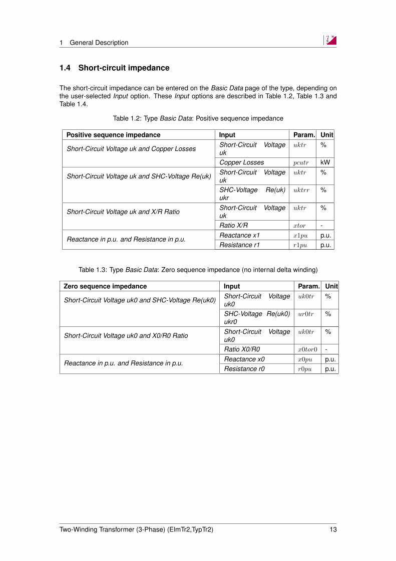
1.4 Short-circuit impedance
The short-circuit impedance can be entered on the Basic Data page of the type, depending onthe user-selected Input option. These Input options are described in Table 1.2, Table 1.3 andTable 1.4.
Table 1.2: Type Basic Data: Positive sequence impedance
Positive sequence impedance Input Param. Unit
Short-Circuit Voltage uk and Copper Losses Short-Circuit Voltageuk
uktr %
Copper Losses pcutr kW
Short-Circuit Voltage uk and SHC-Voltage Re(uk) Short-Circuit Voltageuk
uktr %
SHC-Voltage Re(uk)ukr
uktrr %
Short-Circuit Voltage uk and X/R Ratio Short-Circuit Voltageuk
uktr %
Ratio X/R xtor -
Reactance in p.u. and Resistance in p.u. Reactance x1 x1pu p.u.Resistance r1 r1pu p.u.
Table 1.3: Type Basic Data: Zero sequence impedance (no internal delta winding)
Zero sequence impedance Input Param. Unit
Short-Circuit Voltage uk0 and SHC-Voltage Re(uk0) Short-Circuit Voltageuk0
uk0tr %
SHC-Voltage Re(uk0)ukr0
ur0tr %
Short-Circuit Voltage uk0 and X0/R0 Ratio Short-Circuit Voltageuk0
uk0tr %
Ratio X0/R0 x0tor0 -
Reactance in p.u. and Resistance in p.u. Reactance x0 x0pu p.u.Resistance r0 r0pu p.u.
Two-Winding Transformer (3-Phase) (ElmTr2,TypTr2) 13

1 General Description
Table 1.4: Type Basic Data: Zero sequence impedance: YN-YN; with internal delta winding
Zero sequence impedanceInput Param. Unit
Short-Circuit Voltage uk0 and SHC-Voltage Re(uk0)
HV-SHC-Voltage uk0(LV short-circuit)
uk0hls %
HV-SHC-VoltageRe(uk0)(LV short-circuit)
ur0hls %
HV-SHC-Voltage uk0(LV open)
uk0hlo %
HV-SHC-VoltageRe(uk0)(LV open)
ur0hlo %
LV-SHC-Voltage uk0(HV open)
uk0lho %
LV-SHC-VoltageRe(uk0)(HV open)
ur0lho %
Short-Circuit Voltage uk0 and X0/R0 Ratio
HV-SHC-Voltage uk0(LV short-circuit)
uk0hls %
HV-Ratio X0/R0(LV short-circuit)
xtr0hls %
HV-SHC-Voltage uk0(LV open)
uk0hlo %
HV-Ratio X0/R0(LV open)
xtr0hlo %
LV-SHC-Voltage uk0(HV open)
uk0lho %
LV-Ratio X0/R0(HV open)
xtr0lho %
Reactance in p.u. and Resistance in p.u.
HV-Reactance x0(LV short-circuit)
x0puhls p.u.
HV-Resistance r0(LV short-circuit)
r0puhls p.u.
HV-Reactance x0(LV open)
x0puhlo p.u.
HV-Resistance r0(LV open)
r0puhlo p.u.
LV-Reactance x0(HV open)
x0pulho p.u.
LV-Resistance r0(HV open)
r0pulho p.u.
1.4.1 Positive sequence impedance
If r1pu and x1pu are available as inputs on the Basic Data page of the transformer type:
uktr =√r1pu2 + x1pu2 · 100 (%) (66)
pcutr = r1pu · 1000 · strn (67)
Two-Winding Transformer (3-Phase) (ElmTr2,TypTr2) 14
1 General Description
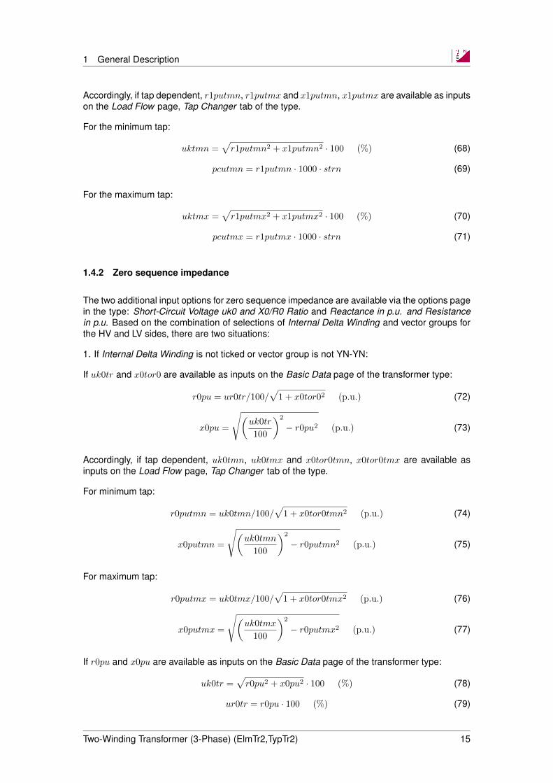
Accordingly, if tap dependent, r1putmn, r1putmx and x1putmn, x1putmx are available as inputson the Load Flow page, Tap Changer tab of the type.
For the minimum tap:
uktmn =√r1putmn2 + x1putmn2 · 100 (%) (68)
pcutmn = r1putmn · 1000 · strn (69)
For the maximum tap:
uktmx =√r1putmx2 + x1putmx2 · 100 (%) (70)
pcutmx = r1putmx · 1000 · strn (71)
1.4.2 Zero sequence impedance
The two additional input options for zero sequence impedance are available via the options pagein the type: Short-Circuit Voltage uk0 and X0/R0 Ratio and Reactance in p.u. and Resistancein p.u. Based on the combination of selections of Internal Delta Winding and vector groups forthe HV and LV sides, there are two situations:
1. If Internal Delta Winding is not ticked or vector group is not YN-YN:
If uk0tr and x0tor0 are available as inputs on the Basic Data page of the transformer type:
r0pu = ur0tr/100/√
1 + x0tor02 (p.u.) (72)
x0pu =
√(uk0tr
100
)2
− r0pu2 (p.u.) (73)
Accordingly, if tap dependent, uk0tmn, uk0tmx and x0tor0tmn, x0tor0tmx are available asinputs on the Load Flow page, Tap Changer tab of the type.
For minimum tap:
r0putmn = uk0tmn/100/√
1 + x0tor0tmn2 (p.u.) (74)
x0putmn =
√(uk0tmn
100
)2
− r0putmn2 (p.u.) (75)
For maximum tap:
r0putmx = uk0tmx/100/√
1 + x0tor0tmx2 (p.u.) (76)
x0putmx =
√(uk0tmx
100
)2
− r0putmx2 (p.u.) (77)
If r0pu and x0pu are available as inputs on the Basic Data page of the transformer type:
uk0tr =√r0pu2 + x0pu2 · 100 (%) (78)
ur0tr = r0pu · 100 (%) (79)
Two-Winding Transformer (3-Phase) (ElmTr2,TypTr2) 15

1 General Description
x0tor0 =x0pu
r0pu(p.u.) (80)
Accordingly, if tap dependent, r0putmn, r0putmx and x0putmn, x0putmx are available as inputson the Load Flow page, Tap Changer tab of the type.
For minimum tap:uk0tmn =
√r0putmn2 + x0putmn2 · 100 (%) (81)
uk0rtmn = r0putmn · 100 (%) (82)
x0tor0tmn =x0putmn
r0putmn(p.u.) (83)
For maximum tap:uk0tmx =
√r0putmx2 + x0putmx2 · 100 (%) (84)
uk0rtmx = r0putmx · 100 (%) (85)
x0tor0tmx =x0putmx
r0putmx(p.u.) (86)
2. If Internal Delta Winding is ticked and vector group is YN-YN:
If uk0(hls,hlo,lho) and xtr0(hls,hlo,lho) are available as inputs on the Basic Data page of the trans-former type:
r0puhls = ur0hls/100/√
1 + xtr02hls (p.u.) (87)
r0puhlo = ur0hlo/100/√
1 + xtr02hlo (p.u.) (88)
r0pulho = ur0lho/100/√
1 + xtr02lho (p.u.) (89)
x0puhls =√
(uk0hls/100)2 − (r0puhls)2 (p.u.) (90)
x0puhlo =√
(uk0hlo/100)2 − (r0puhlo)2 (p.u.) (91)
x0pulho =√
(uk0lho/100)2 − (r0pulho)2 (p.u.) (92)
uk0hls =√r0pu2hls + x0pu2hls · 100 (%) (93)
uk0hlo =√r0pu2hlo + x0pu2hlo · 100 (%) (94)
uk0lho =√r0pu2lho + x0pu2lho · 100 (%) (95)
uk0hls = r0puhls · 100 (%) (96)
uk0hlo = r0puhlo · 100 (%) (97)
uk0lho = r0pulho · 100 (%) (98)
xtr0hls =x0puhlsr0puhls
(p.u.) (99)
xtr0hlo =x0puhlor0puhlo
(p.u.) (100)
xtr0lho =x0pulhor0pulho
(p.u.) (101)
Two-Winding Transformer (3-Phase) (ElmTr2,TypTr2) 16

2 Load Flow Analysis
2 Load Flow Analysis
The Load Flow Calculation in PowerFactory uses the detailed model of the transformer; i.e. allshunt and branch impedances are considered appropriately in the positive- and zero sequencesystems.
As the tap changer is of particular interest in load flow calculations, data relating to the tapchanger is input as follows:
• On the Load Flow page of the transformer element: control data and measurement re-port);
• On the Load Flow page of the transformer type: tap changer positions and tap-dependentimpedance).
2.1 Element data
2.1.1 Measurement report
This can be used for the precise definition of a tap changer. It allows all tap-dependent param-eters to be entered per tap step. If the option According to measurement report is ticked, thecorresponding type parameters are overwritten by their respective element parameters. Theinput parameters are described in Table 2.1.
Table 2.1: Measurement report data (transformer element)
Parameter Description Unit
Voltage Voltage at tap position i. kVAngle Absolute tap angle (parameter ΦU in Fig-
ure 1.5)Degrees ()
uk Short-circuit voltage of the transformer %PCu Copper losses kWAdd. rating Factor Rating factor for consideration of tap-
dependent transformer rating. The addi-tional rating factor is multiplied by the gen-eral rating factor (Rating Factor on the BasicData page).
p.u.
uk0 Short-circuit voltage of the transformer,zero sequence (Only available if button In-clude Zero-Sequence Impedance has beenpressed).
%
ur0 Short-circuit voltage of the transformer, zerosequence (real part) (Only available if but-ton Include Zero-Sequence Impedance hasbeen pressed).
%
The following points should be noted regarding the zero sequence impedance, uk0 and ur0, inthe Measurement report :
Two-Winding Transformer (3-Phase) (ElmTr2,TypTr2) 17

2 Load Flow Analysis
1. If the transformer type options Internal Delta Winding and Tap dependent impedance aredisabled:
• The column uk0 is set to the value of uk0tr (absolute uk0) from the transformer type;
• The column ur0 is set to the value of ur0tr (resistive part ukr0) from the transformertype.
2. If the transformer type option Internal Delta Winding is disabled and Tap dependent impedanceis enabled:
• The column uk0 is set to the corresponding spline-interpolated value of uk0 (at tap)from the transformer type;
• The column ur0 is set to the corresponding spline-interpolated value of ur0 (at tap)from the transformer type.
3. If the transformer type option Internal Delta Winding is enabled and the option Tap depen-dent impedance is disabled:
• The column uk0 is set to the value of the calculated uk0 (absolute uk0) from thetransformer type;
• The column uk0r is set to the value of the calculated ur0 (resistive part ukr0) fromthe transformer type.
2.1.2 Automatic tap changer control
This is activated by setting the corresponding option on the Load Flow page of the transformerelement. Additionally, automatic tap adjustment can be globally enabled or disabled via theLoad Flow Calculation command (ComLdf ). The inputs required for the definition of tap changercontrol are described in Table 2.2.
Two-Winding Transformer (3-Phase) (ElmTr2,TypTr2) 18

2 Load Flow Analysis
Table 2.2: Automatic tap changer control
Parameter Description
According toMeasurementReport
Instead of the type data for the tap-dependent transformervalues, the Measurement report defined in the element is used.
Tap Position Tap position used during the load flow calculation. If AutomaticTap Changing is ticked, this value corresponds to the initial tapposition.
Automatic TapChanging
Activates automatic tap adjustment in load flow analysis.
TapChanger
continuous: An ideal, continuous tap changer is assumed. As aresult, the tap controller can ideally comply with the specifiedcontrol condition. This option is useful for voltage regulators indistribution systems having a very large number of tap steps orfor thyristor-controlled tap changers.discrete: Standard option. Only integer tap positions areconsidered.
ControlledNodeis at
HV: Tap controls the HV sideLV: Tap controls the LV sideEXT: Slave mode. The tap changer follows the tap position ofthe selected Master transformer.
ControlMode
V: Voltage control. For unbalanced load flow analysis, thecontrolled phase needs to be additionally defined.Q: Reactive power controlP: Active power control (only applicable to phase-shifters)
SetpointOnly for V control mode:local : The voltage setpoint and voltage range settings(max./min. voltage) must be entered in the transformer dialogbus target voltage: The voltage setpoint and voltage rangesettings (max./min. voltage) are taken from the controlledbusbar (topological search).
Remote Control Allows for the selection of a busbar different to that at thetransformer terminals (V-control). In the case of P- or Q-control,the flow through any cubicle can be controlled.
Voltage Setpoint V-/Q-/P- reference (depending on selected control mode)Lower/Upperbound
Lower and upper bound of the controlled variable. In the case ofdiscrete tap changers, the tap control can drive the controlledvariable into a permitted band. In the case of continuous tapchangers, the tap controller ideally regulates to the referencepoint.
Voltage control includes optional line drop compensation (LDC). This function controls the volt-age at a remote busbar without measuring the voltage at that busbar. Instead, the value isestimated by measuring the voltage at the HV or LV side of the transformer and simulating thevoltage drop across the line.
The principle of line drop compensation is shown in Figure 2.1 and the corresponding trans-former element input parameters are provided in Table 2.3.
Two-Winding Transformer (3-Phase) (ElmTr2,TypTr2) 19

2 Load Flow Analysis
Figure 2.1: Line drop compensation
Table 2.3: Line drop compensation (for voltage control)
Parameter Description Unit
Currenttransformer rating
Primary CT current rating A
Voltagetransformer ratio
Ratio of the voltage transformer -
RSet, XSet LDC impedance, defined as thevoltage drop at rated current. Itcorresponds to the LDC impedance (inΩ) multiplied by the secondary CTcurrent rating.
V
There is usually more than one possible solution to a load flow problem considering automatictap changer control. In meshed networks in particular, several transformers can control thevoltage in certain areas. In the case of parallel transformers, the problem can usually be solvedby operating the two parallel transformers in master-slave mode.
In a general configuration however, especially when parallel transformers have different short-circuit impedances or different tap steps, the steady-state network solution cannot be easilyobtained. PowerFactory addresses this problem by allowing the user to enter a controller timeconstant, specifying the speed of control actions and hence the participation of several trans-formers regulating the voltage at the same busbar.
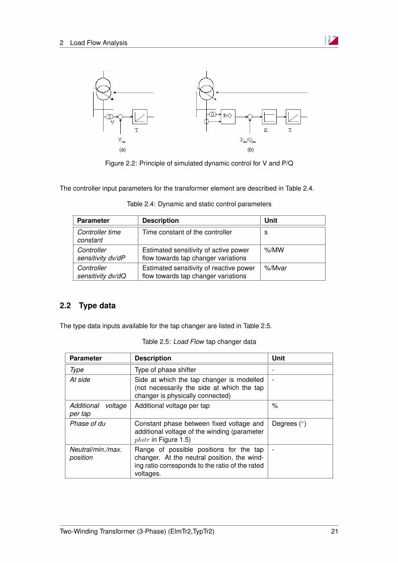
The approach is based on controller block diagrams according to Figure 2.2. In the case offlow controllers (P-/Q-control), the controller sensitivity translating a power mismatch into anequivalent turns-ratio percentage can be entered additionally.
In the load flow algorithm, which only considers steady-state conditions, controller time con-stants and sensitivities are translated into equivalent participation factors.
Two-Winding Transformer (3-Phase) (ElmTr2,TypTr2) 20
2 Load Flow Analysis
(a) (b)
Figure 2.2: Principle of simulated dynamic control for V and P/Q
The controller input parameters for the transformer element are described in Table 2.4.
Table 2.4: Dynamic and static control parameters
Parameter Description Unit
Controller timeconstant
Time constant of the controller s
Controllersensitivity dv/dP
Estimated sensitivity of active powerflow towards tap changer variations
%/MW
Controllersensitivity dv/dQ
Estimated sensitivity of reactive powerflow towards tap changer variations
%/Mvar
2.2 Type data
The type data inputs available for the tap changer are listed in Table 2.5.
Table 2.5: Load Flow tap changer data
Parameter Description Unit
Type Type of phase shifter -At side Side at which the tap changer is modelled
(not necessarily the side at which the tapchanger is physically connected)
-
Additional voltageper tap
Additional voltage per tap %
Phase of du Constant phase between fixed voltage andadditional voltage of the winding (parameterphitr in Figure 1.5)
Degrees ()
Neutral/min./max.position
Range of possible positions for the tapchanger. At the neutral position, the wind-ing ratio corresponds to the ratio of the ratedvoltages.
-
Two-Winding Transformer (3-Phase) (ElmTr2,TypTr2) 21
2 Load Flow Analysis
2.2.1 Tap changer with two taps
The transformer tap model supports the definition of two taps, which may have differing types:
• Ratio/Asym. Phase Shifter
• Ideal Phase Shifter
• Symmetrical Phase Shifter
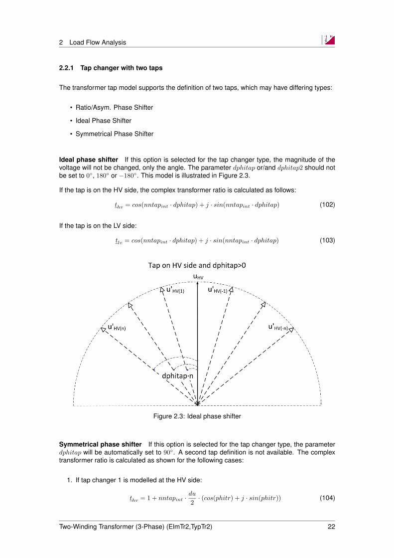
Ideal phase shifter If this option is selected for the tap changer type, the magnitude of thevoltage will not be changed, only the angle. The parameter dphitap or/and dphitap2 should notbe set to 0, 180 or −180. This model is illustrated in Figure 2.3.
If the tap is on the HV side, the complex transformer ratio is calculated as follows:
thv = cos(nntapint · dphitap) + j · sin(nntapint · dphitap) (102)
If the tap is on the LV side:
tlv = cos(nntapint · dphitap) + j · sin(nntapint · dphitap) (103)
Figure 2.3: Ideal phase shifter
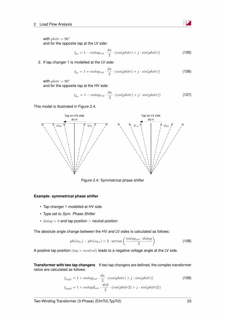
Symmetrical phase shifter If this option is selected for the tap changer type, the parameterdphitap will be automatically set to 90. A second tap definition is not available. The complextransformer ratio is calculated as shown for the following cases:
1. If tap changer 1 is modelled at the HV side:
thv = 1 + nntapint ·du
2· (cos(phitr) + j · sin(phitr)) (104)
Two-Winding Transformer (3-Phase) (ElmTr2,TypTr2) 22
2 Load Flow Analysis
with phitr = 90
and for the opposite tap at the LV side:
tlv = 1− nntapint ·du
2· (cos(phitr) + j · sin(phitr)) (105)
2. If tap changer 1 is modelled at the LV side:
tlv = 1 + nntapint ·du
2· (cos(phitr) + j · sin(phitr)) (106)
with phitr = 90
and for the opposite tap at the HV side:
thv = 1− nntapint ·du
2· (cos(phitr) + j · sin(phitr)) (107)
This model is illustrated in Figure 2.4.
Figure 2.4: Symmetrical phase shifter
Example: symmetrical phase shifter
• Tap changer 1 modelled at HV side
• Type set to Sym. Phase Shifter
• dutap > 0 and tap position > neutral position
The absolute angle change between the HV and LV sides is calculated as follows:
phi(ulv)− phi(uhv) = 2 · arctan
(nntapint · dutap
2
)(108)
A positive tap position (tap > neutral) leads to a negative voltage angle at the LV side.
Transformer with two tap changers If two tap changers are defined, the complex transformerratios are calculated as follows:
ttap1 = 1 + nntapint ·du
2· (cos(phitr) + j · sin(phitr)) (109)
ttap2 = 1 + nntap2int ·du2
2· (cos(phitr2) + j · sin(phitr2))
Two-Winding Transformer (3-Phase) (ElmTr2,TypTr2) 23

2 Load Flow Analysis
If the second tap changer is an ideal phase shifter, the corresponding tap (ttap2) is calculatedaccording to:
ttap2 = cos(nntap2int · dphitap2) + j · sin(nntap2int · dphitap2) (110)
and with the relative tap positions:
nntapint = nntap0− nntap (111)nntap2int = nntap02− nntap2
The transformer ratios for the HV and LV sides are calculated as follows:
1. If both tap changers are modelled at the HV side:
thv = ttap1 · ttap2 (112)
tlv = 1
2. If both tap changers are modelled at the LV side:
thv = 1 (113)tlv = ttap1 · ttap2
3. If tap changer 1 is at the HV side and tap changer 2 is at the LV side:
thv = ttap1 (114)
tlv = ttap2
4. If tap changer 1 is at the LV side and tap changer 2 is at the HV side:
thv = ttap2 (115)
tlv = ttap1
The internal voltages and currents are transferred accordingly:
u′hv =uhvthv
(116)
i′hv = ihv · t∗hv
and for the LV-side voltage:
u′lv =ulvtlv
(117)
i′lv = ilv · t∗lv
Tap dependent impedance Data relating to the tap dependent impedance can be enteredwhen the Tap dependent impedance option in the type has been selected. Parameters thatcan be considered to be tap dependent are the short-circuit impedances and copper losses(short-circuit resistance) in the positive- and zero sequence systems. For tap positions betweenminimum and neutral, and between neutral and maximum, tap dependent parameters are inter-polated using splines.
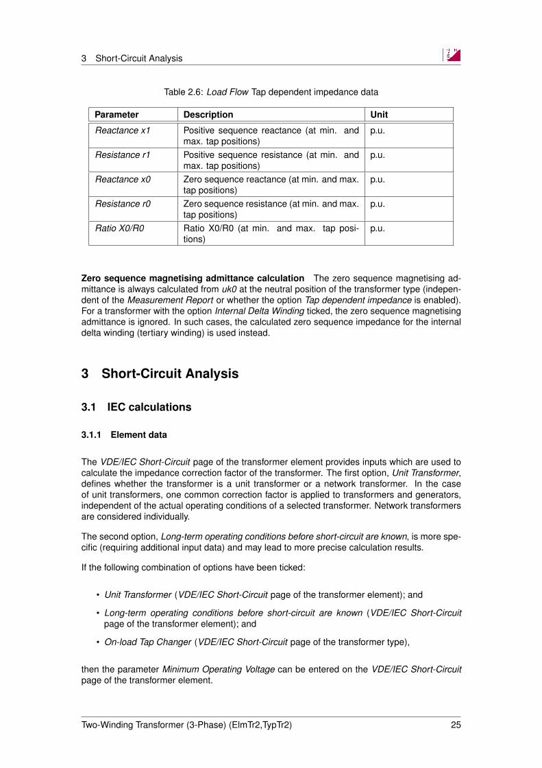
Transformer type Load Flow tap dependent impedance data is shown in Table 2.6.
Two-Winding Transformer (3-Phase) (ElmTr2,TypTr2) 24
3 Short-Circuit Analysis
Table 2.6: Load Flow Tap dependent impedance data
Parameter Description Unit
Reactance x1 Positive sequence reactance (at min. andmax. tap positions)
p.u.
Resistance r1 Positive sequence resistance (at min. andmax. tap positions)
p.u.
Reactance x0 Zero sequence reactance (at min. and max.tap positions)
p.u.
Resistance r0 Zero sequence resistance (at min. and max.tap positions)
p.u.
Ratio X0/R0 Ratio X0/R0 (at min. and max. tap posi-tions)
p.u.
Zero sequence magnetising admittance calculation The zero sequence magnetising ad-mittance is always calculated from uk0 at the neutral position of the transformer type (indepen-dent of the Measurement Report or whether the option Tap dependent impedance is enabled).For a transformer with the option Internal Delta Winding ticked, the zero sequence magnetisingadmittance is ignored. In such cases, the calculated zero sequence impedance for the internaldelta winding (tertiary winding) is used instead.
3 Short-Circuit Analysis
3.1 IEC calculations
3.1.1 Element data
The VDE/IEC Short-Circuit page of the transformer element provides inputs which are used tocalculate the impedance correction factor of the transformer. The first option, Unit Transformer,defines whether the transformer is a unit transformer or a network transformer. In the caseof unit transformers, one common correction factor is applied to transformers and generators,independent of the actual operating conditions of a selected transformer. Network transformersare considered individually.
The second option, Long-term operating conditions before short-circuit are known, is more spe-cific (requiring additional input data) and may lead to more precise calculation results.
If the following combination of options have been ticked:
• Unit Transformer (VDE/IEC Short-Circuit page of the transformer element); and
• Long-term operating conditions before short-circuit are known (VDE/IEC Short-Circuitpage of the transformer element); and
• On-load Tap Changer (VDE/IEC Short-Circuit page of the transformer type),
then the parameter Minimum Operating Voltage can be entered on the VDE/IEC Short-Circuitpage of the transformer element.
Two-Winding Transformer (3-Phase) (ElmTr2,TypTr2) 25

5 EMT-Simulation
3.1.2 Type data
Short-circuit calculations according to IEC assume that the shunt impedances (i.e. magnetisingreactances and iron losses) in the positive- and negative sequence are neglected. The shuntimpedances in the zero sequence however, must be considered. These input parameters areavailable on the VDE/IEC Short-Circuit page of the type dialog.
The short-circuit calculation according to IEC distinguishes between no-load and on-load tapchangers. Different impedance correction factors apply for each group. On-load variation of thetap changer can be ticked on the VDE/IEC Short-Circuit page of the type dialog.
4 RMS-Simulation
The model used by the RMS simulation is identical to the load flow model. However, tap con-troller definitions are not considered. For the simulation of tap controllers, a separate dynamicmodel must be defined that can be interfaced with the transformer using the input variablenntapin (tap-input).
5 EMT-Simulation
For simulating non-linear, electromagnetic transients such as transformer inrush currents orferro-resonance, core saturation needs to be included in the model of the transformer. Thesaturation can be defined in the transformer type, as described in Section 5.2.1. In addition,depending on the frequencies involved in the transient simulation, the transformer model hasto account for the stray capacitances between windings and winding to ground. These can bedefined in the transformer element, as described in Section 5.1.1
5.1 Element data
5.1.1 Stray capacitances
In high frequency EMT applications, e.g. switching or lightning studies, transformer capaci-tances should be considered.
The stray capacitances of a transformer do not only depend on the physical characteristics ofthe transformer (i.e. the length of the windings, insulating material, core dimensions, etc) butalso on the installation environment as well (indoor or outdoor transformer; proximity to othergrounded components, walls, etc).
The following capacitances can be defined after ticking the Consider Capacitances option onthe EMT-Simulation page of the transformer element:
Capacitance HV to ground : applies to the positive- and zero sequence
Capacitance LV to ground : applies to the positive- and zero sequence
Capacitance HV-LV, positive sequence
Capacitance HV-LV, zero sequence
Two-Winding Transformer (3-Phase) (ElmTr2,TypTr2) 26
5 EMT-Simulation
For typical values please refer to [4].
5.2 Type data
5.2.1 Saturation characteristic
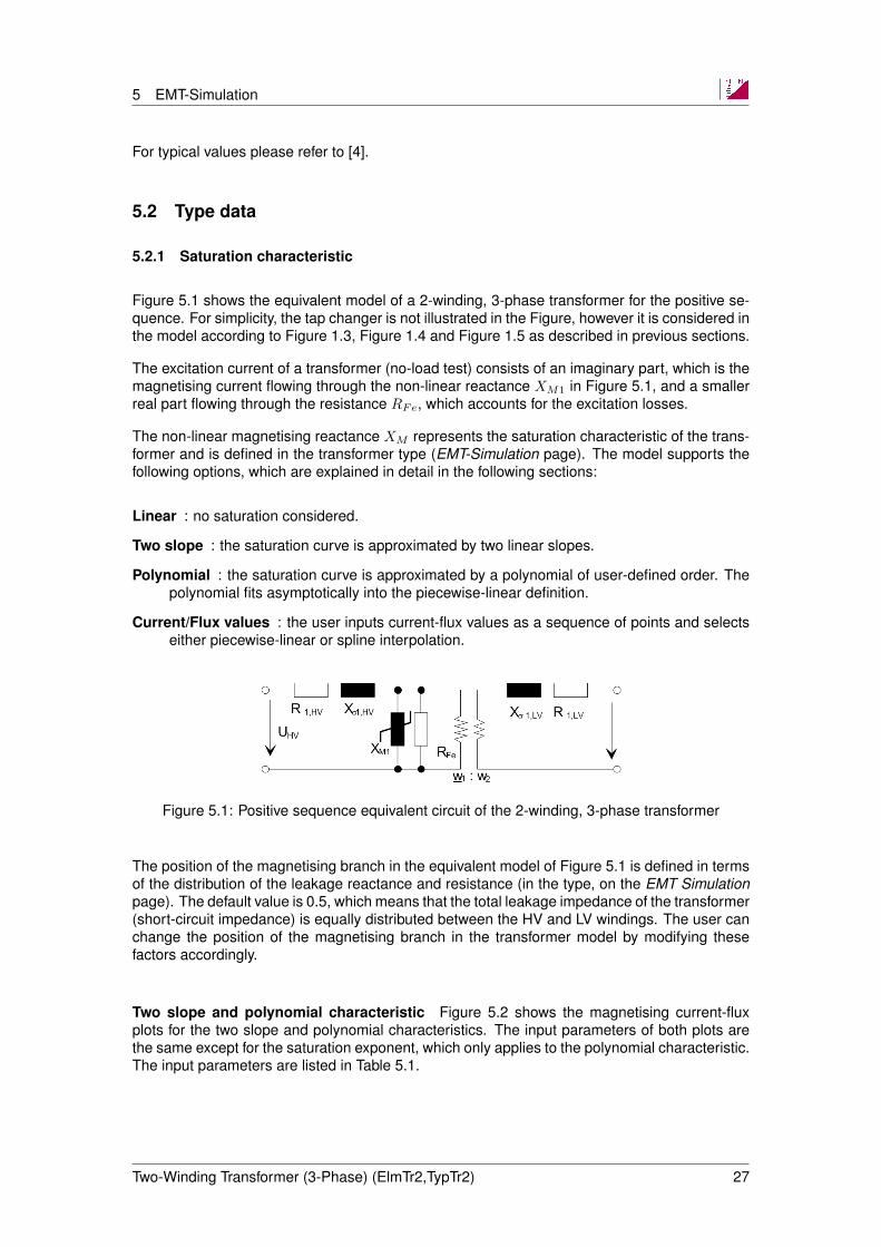
Figure 5.1 shows the equivalent model of a 2-winding, 3-phase transformer for the positive se-quence. For simplicity, the tap changer is not illustrated in the Figure, however it is considered inthe model according to Figure 1.3, Figure 1.4 and Figure 1.5 as described in previous sections.
The excitation current of a transformer (no-load test) consists of an imaginary part, which is themagnetising current flowing through the non-linear reactance XM1 in Figure 5.1, and a smallerreal part flowing through the resistance RFe, which accounts for the excitation losses.
The non-linear magnetising reactance XM represents the saturation characteristic of the trans-former and is defined in the transformer type (EMT-Simulation page). The model supports thefollowing options, which are explained in detail in the following sections:
Linear : no saturation considered.
Two slope : the saturation curve is approximated by two linear slopes.
Polynomial : the saturation curve is approximated by a polynomial of user-defined order. Thepolynomial fits asymptotically into the piecewise-linear definition.
Current/Flux values : the user inputs current-flux values as a sequence of points and selectseither piecewise-linear or spline interpolation.
Figure 5.1: Positive sequence equivalent circuit of the 2-winding, 3-phase transformer
The position of the magnetising branch in the equivalent model of Figure 5.1 is defined in termsof the distribution of the leakage reactance and resistance (in the type, on the EMT Simulationpage). The default value is 0.5, which means that the total leakage impedance of the transformer(short-circuit impedance) is equally distributed between the HV and LV windings. The user canchange the position of the magnetising branch in the transformer model by modifying thesefactors accordingly.
Two slope and polynomial characteristic Figure 5.2 shows the magnetising current-fluxplots for the two slope and polynomial characteristics. The input parameters of both plots arethe same except for the saturation exponent, which only applies to the polynomial characteristic.The input parameters are listed in Table 5.1.
Two-Winding Transformer (3-Phase) (ElmTr2,TypTr2) 27

5 EMT-Simulation
Figure 5.2: Two slope and polynomial saturation curves
Table 5.1: Two-slope and polynomial saturation characteristic input parameters
Parameter Description Unit
Knee Flux Knee-point of asymptotic piece-wiselinear characteristic. Typical valuearound 1.1 to 1.2 times the rated flux.
p.u.
Linear(unsaturated)reactance
Magnetising reactance for unsaturatedconditions Lunsat.In p.u. values, the linear reactance isequal to the reciprocal of themagnetising current (reactive part ofthe exciting current).
p.u.
Saturatedreactance
Magnetising reactance for saturatedconditions Lsat.
p.u.
Saturationexponent
Exponent of polynomial representation(ksat). Typical values are 9, 13, 15.The higher the exponent the sharperthe saturation curve.
-
The reciprocal of the p.u. unsaturated reactance is equal to the p.u. magnetising current (i.e.the imaginary part of the exciting current). Therefore, PowerFactory automatically adjusts theunsaturated reactance based on the no-load current and no-load losses entered on the LoadFlow page of the type, and vice-versa:
1
XM=
√(IMIR
)2
−(PexcSR
)2
(118)
where:
IM : magnitude of the exciting current in the no-load test. This can be entered on the LoadFlow page of the transformer type, under Magnetising Impedance; No Load Current (in%);
Two-Winding Transformer (3-Phase) (ElmTr2,TypTr2) 28
5 EMT-Simulation
Pexc : excitation losses in the no-load test;
IR, SR : rated current and apparent power of the transformer, respectively.
The saturated reactance is also referred as the air-core reactance; it is fairly low compared tothe unsaturated reactance. Typical values for two-winding transformers are 1 to 2 times theshort-circuit inductance and 3 to 4 times for auto transformers [1].
The polynomial characteristic uses (119) to fit the curve asymptotically into the piecewise-lineardefinition. The higher the exponent, the sharper the saturation curve:
iMX =ΨM
lM·
(1 +
∣∣∣∣ΨM
Ψ0
∣∣∣∣ksat)
(p.u.) (119)
where:
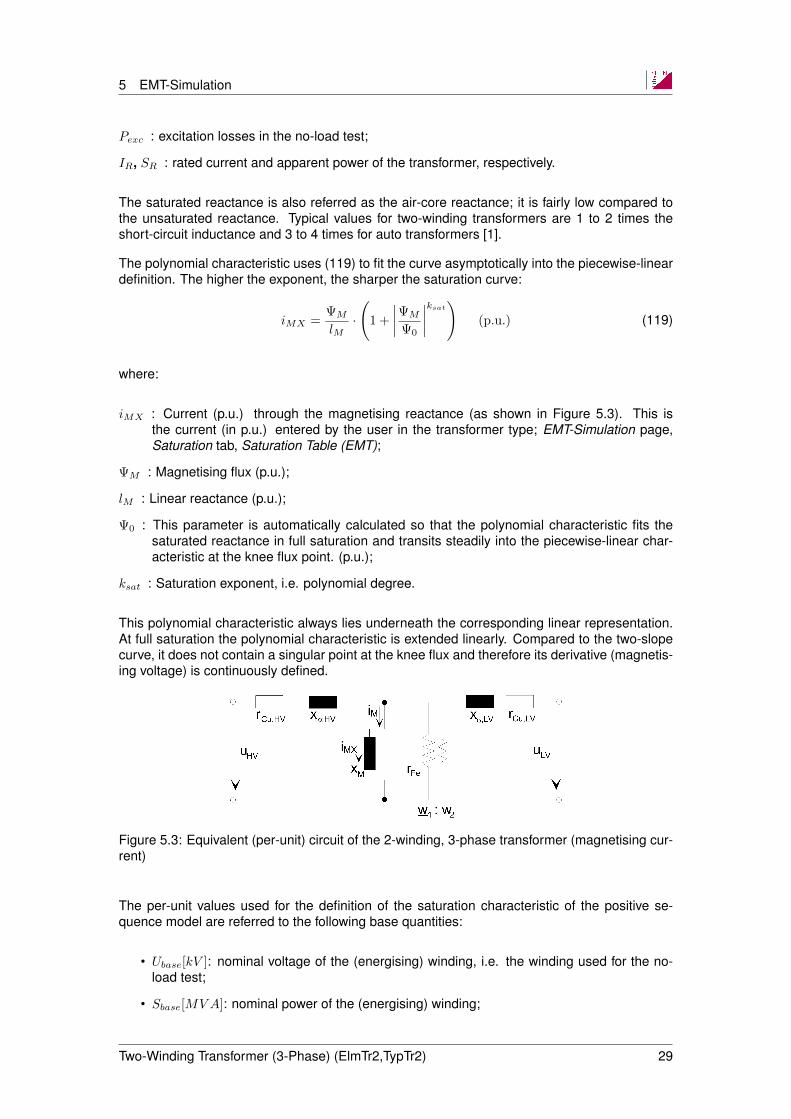
iMX : Current (p.u.) through the magnetising reactance (as shown in Figure 5.3). This isthe current (in p.u.) entered by the user in the transformer type; EMT-Simulation page,Saturation tab, Saturation Table (EMT);
ΨM : Magnetising flux (p.u.);
lM : Linear reactance (p.u.);
Ψ0 : This parameter is automatically calculated so that the polynomial characteristic fits thesaturated reactance in full saturation and transits steadily into the piecewise-linear char-acteristic at the knee flux point. (p.u.);
ksat : Saturation exponent, i.e. polynomial degree.
This polynomial characteristic always lies underneath the corresponding linear representation.At full saturation the polynomial characteristic is extended linearly. Compared to the two-slopecurve, it does not contain a singular point at the knee flux and therefore its derivative (magnetis-ing voltage) is continuously defined.
Figure 5.3: Equivalent (per-unit) circuit of the 2-winding, 3-phase transformer (magnetising cur-rent)
The per-unit values used for the definition of the saturation characteristic of the positive se-quence model are referred to the following base quantities:
• Ubase[kV ]: nominal voltage of the (energising) winding, i.e. the winding used for the no-load test;
• Sbase[MVA]: nominal power of the (energising) winding;
Two-Winding Transformer (3-Phase) (ElmTr2,TypTr2) 29
5 EMT-Simulation
• Ibase[A] =Sbase[MVA]√3 · Ubase[kV ]
× 1000
• Ψbase[V · s] =Ubase[kV ]/
√3
2πf [kHz]× 1000
• Lbase[H] =
(U2base[kV ]
Sbase[MVA]
)· 1
2πf [Hz]
Ψ0 = ΨMknee · e ·
−log ·
(bmsat
bm− 1
)(ksat + 1)
ksat
(p.u.) (120)
iknee =bm
ω0·ΨMknee ·
(1 +
ΨMknee
Ψ0
)ksat
(p.u.) (121)
For Ψ(a, b, c) > ΨMknee:
iMX(a, b, c) = iknee +bmsat
ω0· (Ψ(a, b, c)−ΨMknee) (p.u.) (122)
For Ψ(a, b, c) < −ΨMknee:
iMX(a, b, c) = −iknee +bmsat
ω0· (Ψ(a, b, c) + ΨMknee) (p.u.) (123)
otherwise:
iMX(a, b, c) =bmsat
ω0·Ψ(a, b, c) ·
(1 +
∣∣∣∣∣(
Ψ(a, b, c)
Ψ0
)ksat
∣∣∣∣∣)
(p.u.) (124)
and:iM (a, b, c) = uM (a, b, c) · gm(a, b, c) + iMX(a, b, c) (p.u.) (125)
where gm(a, b, c) are available as input signals for EMT simulations and are initialised using gm,which is defined as:
gm = pfe/1000/strn (p.u.) (126)
and:ymag =
curmg
100(p.u.) (127)
bm =√ymag2 − gm2 · ω0 (p.u.) (128)
orbm =
ω0
xmlin(p.u.) (129)
ω0 = 2 · π · fnom (rad/s) (130)
Two-Winding Transformer (3-Phase) (ElmTr2,TypTr2) 30
5 EMT-Simulation
bmsat =1
xmair· ω0 (p.u.) (131)
ΨMknee =ksat + 1
ksat·Ψ0 (p.u.) (132)
and xmair is the saturated reactance (p.u.), Ψ0 is the knee flux (p.u.), and ksat is the saturationexponent.
Current-flux values The saturation curve can also be defined in terms of measured current-flux values, and a choice of either piecewise linear or spline interpolation is available.
The current-flux values in the table are peak values in p.u. In a power transformer with im-pressed voltage, the magnetising flux in p.u. is equal to the magnetising voltage in p.u., thusflux and voltage are interchangeable and the p.u. current-flux curve also represents a p.u.current-voltage curve. Furthermore, it can be assumed that the applied voltage remains fairlylinear during no-load tests, hence the ratio of RMS to peak values of the voltage is given by
√2.
The magnetising current, on the other hand, is distorted (i.e. non-sinusoidal) because of thesaturation curve. Consequently, the ratio of RMS to peak value of the magnetising current is nolonger
√2 and the user is required to enter true peak values in the table.
The base quantities of the p.u. values in the current-flux table are also referred to the peakvalues of the corresponding nominal variables:
Ibase[A] =√
2× Sbase[MVA]√3 · Ubase[kV ]
× 1000
Ψbase[V · s] =√
2× Ubase[kV ]/√
3
2πf [kHz]× 1000
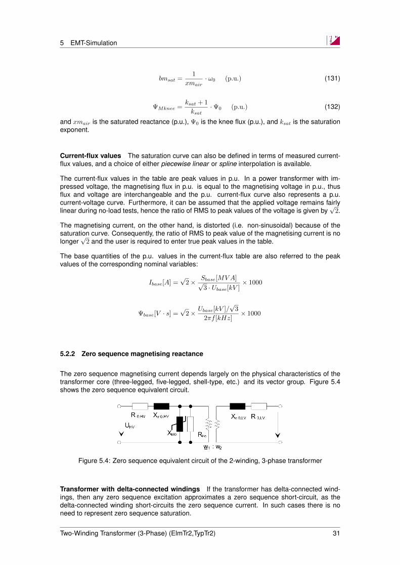
5.2.2 Zero sequence magnetising reactance
The zero sequence magnetising current depends largely on the physical characteristics of thetransformer core (three-legged, five-legged, shell-type, etc.) and its vector group. Figure 5.4shows the zero sequence equivalent circuit.
Figure 5.4: Zero sequence equivalent circuit of the 2-winding, 3-phase transformer
Transformer with delta-connected windings If the transformer has delta-connected wind-ings, then any zero sequence excitation approximates a zero sequence short-circuit, as thedelta-connected winding short-circuits the zero sequence current. In such cases there is noneed to represent zero sequence saturation.
Two-Winding Transformer (3-Phase) (ElmTr2,TypTr2) 31

5 EMT-Simulation
Transformer without delta-connected windings If the transformer does not have delta-connected windings, then the zero sequence excitation current is generally higher than thepositive sequence excitation current and largely depends on the core type.
To account for the higher zero sequence linear exciting current when no delta-connected wind-ing is available, PowerFactory allows for the definition of a linear (unsaturated) zero sequencemagnetising impedance. This zero sequence magnetising impedance and its R/X ratio are de-fined in the type, on the Load Flow page. The input parameters are displayed in the dialogdepending on the vector group (and are therefore hidden in cases where a delta-connectedwinding has been selected).
To account for the core type dependency of the zero sequence saturation characteristic, thetransformer model supports the following two options on the EMT-Simulation page of the type:
3-Limb core: this option should be used for three-legged core designs. In this core type, thefluxes are roughly equal in the three legs and must therefore return outside the corethrough the air-gap and the tank. Because of the fact that the air-gap and the tanks arenon-magnetic, the zero sequence magnetising current is almost linear and therefore themodel uses the linear zero sequence magnetising impedance defined on the Load Flowpage. In other words, zero sequence saturation effects are not considered.
5-Limb core: this option should be used for five-legged and shell-type cores. As the zerosequence fluxes return inside the core, the model uses the saturation characteristic (ofthe positive sequence) in the zero sequence magnetising reactance as well.
5.3 Residual flux
The residual flux is the magnetising flux that remains in the core after the transformer hasbeen switched off. A residual flux, as opposed to a remnant flux1, implies the circulation of amagnetising current (ΨM = LM · IM ).
Once the transformer has been switched off, this magnetising current circulates through theno-load losses resistance, Rm, and de-magnetises the core. The flux then decays exponentiallywith a time constant, Lm/Rm, where Lm is the linear magnetising inductance. To simulate thedecaying magnetising current, and hence the decaying residual flux, it is necessary to definethe no-load losses. Otherwise, if Rm = 0, the magnetising current cannot circulate and Pow-erFactory will automatically set the residual flux to zero as soon as the transformer has beenswitched off.
The user can also define the residual flux in the EMT simulation via a parameter event. Theresidual flux is entered in αβγ-components using the following signals:
psimd: residual flux (ψα), α-component in p.u.
psimq: residual flux (ψβ), β-component in p.u.
psim0: residual flux (ψγ), γ-component in p.u.
1The remnant flux is the flux at i=0 in the hysteresis curve
Two-Winding Transformer (3-Phase) (ElmTr2,TypTr2) 32

6 Harmonics/Power Quality
The αβγ-fluxes are transformed to abc-fluxes (phase or natural components) as follows:
ψαψβψγ
=
2
3−1
3
1
3
01√3− 1√
31
3
1
3
1
3
×ψaψbψc
The inverse transformation is given by:
ψaψbψc
=
1 0 1
−1
2
√3
21
−1
2−√
3
21
×ψαψβψγ
The calculation parameters c:psim c, c:psim b and c:psim c give the resulting flux (as a resultof the simulation) in natural components for the phases a, b and c, respectively.
Generally speaking, it is difficult to reliably predict the residual flux of a transformer. However, asthe residual flux strongly influences the amplitude of inrush currents, it should be considered inthe model. If it is not known, typical maximum values between 0.8 and 0.9 p.u. can be assumedfor worst-case conditions.
6 Harmonics/Power Quality
In order to accurately model the high frequency effects of transformers, additional capacitancesneed to be considered, as shown in Figure 6.1. These capacitances are equivalent capaci-tances of the model and do not represent the actual winding capacitances. In order to obtainequivalent capacitances from winding capacitances, the winding connection (D/Y) must be ad-ditionally considered. The high frequency model according to Figure 6.1 provides an accuratefrequency response with respect to voltages and currents at the transformer terminals. How-ever, internal effects such as internal voltage stress cannot be simulated.
Two-Winding Transformer (3-Phase) (ElmTr2,TypTr2) 33

6 Harmonics/Power Quality
(a)
(b)
Figure 6.1: HF model for (a) external capacitances in the positive sequence system; and (b)zero sequence system
6.1 K-Factor, Factor-K and FHL
Transformers experience increased losses in the presence of power system harmonic currents.In the worst-case, excessive losses can lead to transformer overheating and subsequent failure.To assist in the selection of an appropriate transformer, various factors are available:
• K-factor (UL 1562); mainly used in the US
• Factor-K (BS 7821); mainly used in Europe
• Harmonic Loss Factor (FHL) (IEEE C.57.110-1998)
These factors are indicators of the ability of a transformer to handle harmonic loads. Non-linearloads in the power system produce harmonic currents which are capable of causing unwantedside-effects, including increased transformer losses. Transformer losses are comprised of:
• Stray magnetic losses in the transformer core; and
• Eddy current and resistive losses in the transformer windings.
In the presence of harmonic currents, eddy current losses can become large because theyincrease with the square of the frequency. The eddy current loss at harmonic order h is given
Two-Winding Transformer (3-Phase) (ElmTr2,TypTr2) 34
6 Harmonics/Power Quality
by:Ph = Pf · Ih2 · h2 (133)
where Pf is the eddy current loss at the fundamental frequency f ; Ph is the eddy current loss atharmonic order h; and Ih is the fraction of total rms load current at harmonic order h. The totaleddy current loss is given by the following summation:
Pt = Pf ·hmax∑h=1
Ih2 · h2 (134)
6.1.1 K-Factor
The K-Factor accounts for the increased eddy current losses due to harmonic currents. Math-ematically, it is the ratio of eddy current losses in the presence of non-linear and linear loads[3]:
K =PtPf
=
hmax∑h=1
Ih2 · h2 (135)
Following the calculation of the K-Factor, an appropriate K-transformer can then be selectedwhich has a higher K-rating.
6.1.2 Factor-K
The factor-K was introduced in [2] and is described mathematically by:
K =
[1 +
e
1 + e
(I1I
)2
·hmax∑h=2
(hq(IhI1
)2)]0.5
(136)
where e is the eddy current loss at the fundamental frequency divided by the loss due to a dccurrent equal to the rms values of the sinusoidal current, both at reference temperature. Theharmonic order is represented by h, and the exponential constant, q, depends on the type ofwinding and the frequency. Typical values are 1.7 for transformers utilising round/rectangularcross-section conductors in both windings, and 1.5 for transformers which use foil-type lowvoltage windings. This value should be available from the transformer manufacturer. I is therms value of the sinusoidal current including all harmonics, and is given by:
I =
(hmax∑h=1
(Ih)2
)0.5
= I1
[hmax∑h=1
(IhI1
)2]0.5
(137)
6.1.3 FHL
The FHL is described mathematically by [3]:
FHL =
∑hmax
h=1
[IhI1
]2· h2
∑hmax
h=1
[IhI1
]2 (138)
Two-Winding Transformer (3-Phase) (ElmTr2,TypTr2) 35

6 Harmonics/Power Quality
6.1.4 Input data
For the calculation of any of these factors, the ratio of eddy current losses to copper lossesshould be entered in the transformer type (Harmonics/Power Quality page) using input param-eter Ratio: eddy current-/copper losses. By default, this value is set to 0.1 (i.e. 10%).
Additionally, for the calculation of Factor-K, the exponent q (from (136)) must be entered inthe Harmonic Load Flow command (ComHldf ) via input parameter Calculation of Factor-K forTransformers (Exponent).
6.2 Frequency-dependent zero sequence impedance
On the Harmonics page of the transformer type, a frequency-dependent zero sequence impedancecan be defined. If the zero sequence impedance is included in the Measurement Report, thecharacteristic should be defined as relative otherwise the value in the Measurement Report willbe overwritten. The distribution factor for the zero sequence impedance will be kept constantand is obtained as follows:
• From the transformer type, Distribution of Zero Sequ. Leakage-Impedances (zx0hl h) fora transformer with no Internal Delta Winding;
• For a transformer with an Internal Delta Winding, the distribution factors are calculated asin Section 1.3.
Two-Winding Transformer (3-Phase) (ElmTr2,TypTr2) 36
7 Modelling Details and Application Tips
7 Modelling Details and Application Tips
7.1 Reference values
All transformer parameters entered in p.u. or % are referred to the transformer ratings. Trans-former rated voltages different from nominal busbar voltages are correctly considered.
7.2 Zero sequence models for common vector groups
7.2.1 Yd-transformer
This model is described in detail in Section 1.1.2 as a general example for zero sequencesystem modelling.
If no accurate data is available from the manufacturer, the following estimations can be used forthe zero sequence impedance voltages as seen from the grounded side:
Core-type transformer (3-limb) : usc,0 = 0.85 · Usc,1; uRr,0 = 0
Shell-type transformer (4/5-limb) : usc,0 = 1.0 · Usc,1; uRr,0 = 0
where usc,0 is the positive sequence impedance voltage.
It should be taken into account that when modelling magnetic flux saturation characteristics,transformer types with 3 or 4/5 limbs behave differently. In the 3-limb design, the zero sequenceflux defined by (139) is not guided via the transformer limbs but uses parallel paths (e.g. throughthe transformer vessel, oil, ...) and can therefore be modelled linearly without saturation effects.
Ψ0 =1
3· (ΨA + ΨB + ΨC) (139)
7.2.2 YNyn/YNy/Yyn-transformer
The zero sequence equivalent circuit diagram of the YNyn transformers is depicted in Figure 7.1.The equivalent circuit diagram of star connected transformers with isolated star point can bederived from this equivalent circuit by assuming infinite grounding impedances at the respectiveside.
Two-Winding Transformer (3-Phase) (ElmTr2,TypTr2) 37
7 Modelling Details and Application Tips
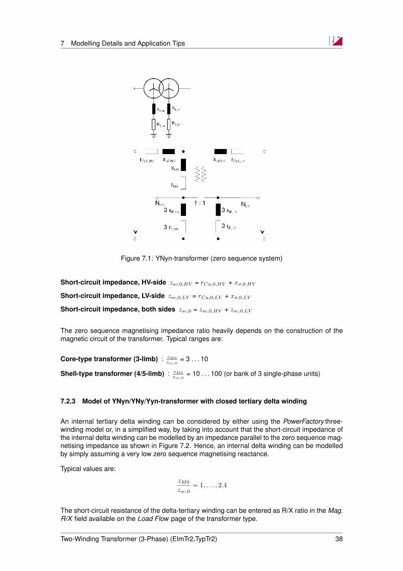
Figure 7.1: YNyn-transformer (zero sequence system)
Short-circuit impedance, HV-side zsc,0,HV = rCu,0,HV + xσ,0,HV
Short-circuit impedance, LV-side zsc,0,LV = rCu,0,LV + xσ,0,LV
Short-circuit impedance, both sides zsc,0 = zsc,0,HV + zsc,0,LV
The zero sequence magnetising impedance ratio heavily depends on the construction of themagnetic circuit of the transformer. Typical ranges are:
Core-type transformer (3-limb) : zM0
zsc,0= 3 . . . 10
Shell-type transformer (4/5-limb) : zM0
zsc,0= 10 . . . 100 (or bank of 3 single-phase units)
7.2.3 Model of YNyn/YNy/Yyn-transformer with closed tertiary delta winding
An internal tertiary delta winding can be considered by either using the PowerFactory three-winding model or, in a simplified way, by taking into account that the short-circuit impedance ofthe internal delta winding can be modelled by an impedance parallel to the zero sequence mag-netising impedance as shown in Figure 7.2. Hence, an internal delta winding can be modelledby simply assuming a very low zero sequence magnetising reactance.
Typical values are:
zM0
zsc,0= 1, . . . , 2.4
The short-circuit resistance of the delta-tertiary winding can be entered as R/X ratio in the Mag.R/X field available on the Load Flow page of the transformer type.
Two-Winding Transformer (3-Phase) (ElmTr2,TypTr2) 38

7 Modelling Details and Application Tips
Figure 7.2: Zero sequence model of YNYnd-transformer
7.2.4 Model of YNzn/YNz/Zyn-transformer
A zig-zag winding completely decouples the primary and secondary sides of the zero sequencesystem, as shown in Figure 7.3.
Figure 7.3: YNzn-transformer (zero sequence system) with HV side tap changer (detailed rep-resentation)
7.3 Auto transformer model
The PowerFactory model for the auto transformer is a special case of the 2-winding star/star(Yy)-transformer. The option Auto Transformer can be ticked on the Basic Data page of theelement, however this option is only visible when the transformer has no assigned type, or
Two-Winding Transformer (3-Phase) (ElmTr2,TypTr2) 39
7 Modelling Details and Application Tips
when the assigned type has its vector group set to YY.
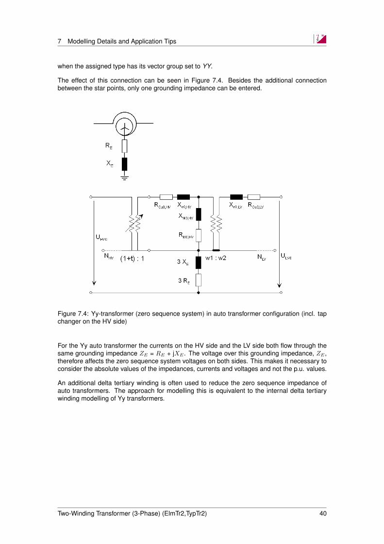
The effect of this connection can be seen in Figure 7.4. Besides the additional connectionbetween the star points, only one grounding impedance can be entered.
Figure 7.4: Yy-transformer (zero sequence system) in auto transformer configuration (incl. tapchanger on the HV side)
For the Yy auto transformer the currents on the HV side and the LV side both flow through thesame grounding impedance ZE = RE + jXE . The voltage over this grounding impedance, ZE ,therefore affects the zero sequence system voltages on both sides. This makes it necessary toconsider the absolute values of the impedances, currents and voltages and not the p.u. values.
An additional delta tertiary winding is often used to reduce the zero sequence impedance ofauto transformers. The approach for modelling this is equivalent to the internal delta tertiarywinding modelling of Yy transformers.
Two-Winding Transformer (3-Phase) (ElmTr2,TypTr2) 40

7 Modelling Details and Application Tips
Figure 7.5: YYd-transformer (zero sequence system) in auto transformer configuration
Two-Winding Transformer (3-Phase) (ElmTr2,TypTr2) 41
8 Input/Output Definitions of Dynamic Models
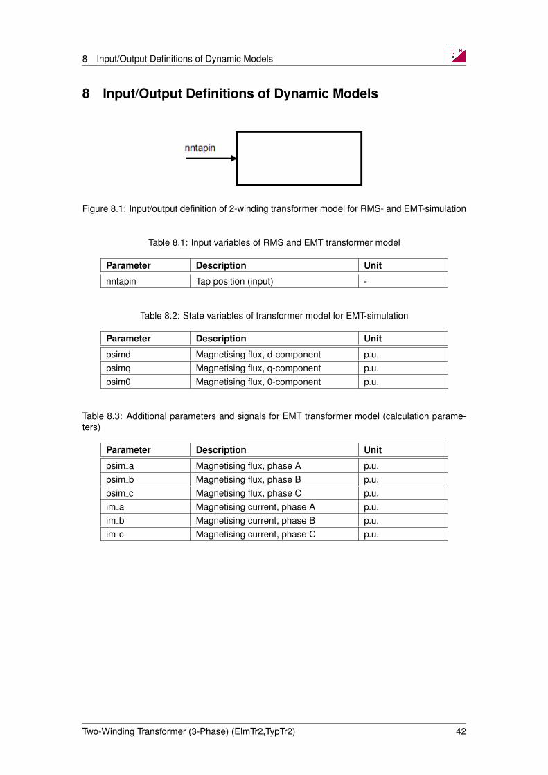
8 Input/Output Definitions of Dynamic Models
Figure 8.1: Input/output definition of 2-winding transformer model for RMS- and EMT-simulation
Table 8.1: Input variables of RMS and EMT transformer model
Parameter Description Unit
nntapin Tap position (input) -
Table 8.2: State variables of transformer model for EMT-simulation
Parameter Description Unit
psimd Magnetising flux, d-component p.u.psimq Magnetising flux, q-component p.u.psim0 Magnetising flux, 0-component p.u.
Table 8.3: Additional parameters and signals for EMT transformer model (calculation parame-ters)
Parameter Description Unit
psim a Magnetising flux, phase A p.u.psim b Magnetising flux, phase B p.u.psim c Magnetising flux, phase C p.u.im a Magnetising current, phase A p.u.im b Magnetising current, phase B p.u.im c Magnetising current, phase C p.u.
Two-Winding Transformer (3-Phase) (ElmTr2,TypTr2) 42
9 Input Parameter Definitions
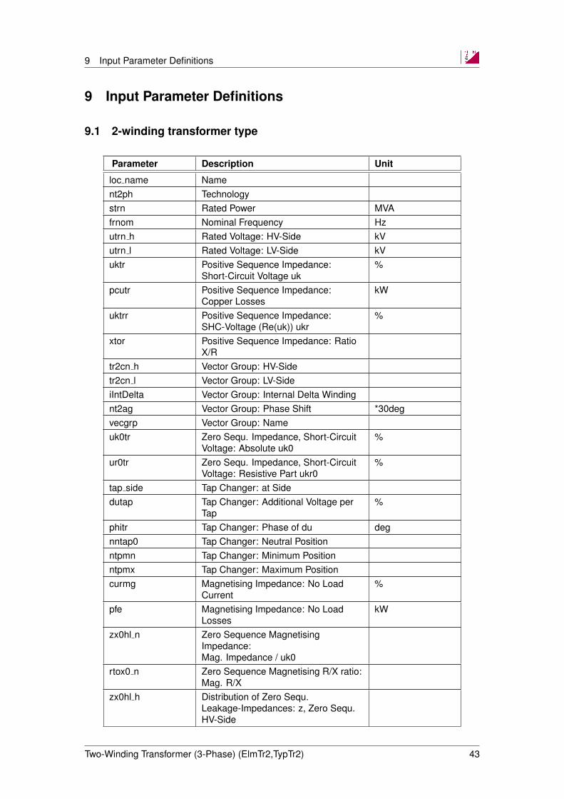
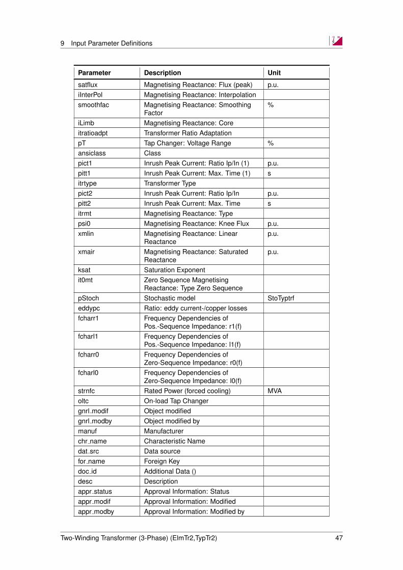
9 Input Parameter Definitions
9.1 2-winding transformer type
Parameter Description Unit
loc name Nament2ph Technologystrn Rated Power MVAfrnom Nominal Frequency Hzutrn h Rated Voltage: HV-Side kVutrn l Rated Voltage: LV-Side kVuktr Positive Sequence Impedance:
Short-Circuit Voltage uk%
pcutr Positive Sequence Impedance:Copper Losses
kW
uktrr Positive Sequence Impedance:SHC-Voltage (Re(uk)) ukr
%
xtor Positive Sequence Impedance: RatioX/R
tr2cn h Vector Group: HV-Sidetr2cn l Vector Group: LV-SideiIntDelta Vector Group: Internal Delta Windingnt2ag Vector Group: Phase Shift *30degvecgrp Vector Group: Nameuk0tr Zero Sequ. Impedance, Short-Circuit
Voltage: Absolute uk0%
ur0tr Zero Sequ. Impedance, Short-CircuitVoltage: Resistive Part ukr0
%
tap side Tap Changer: at Sidedutap Tap Changer: Additional Voltage per
Tap%
phitr Tap Changer: Phase of du degnntap0 Tap Changer: Neutral Positionntpmn Tap Changer: Minimum Positionntpmx Tap Changer: Maximum Positioncurmg Magnetising Impedance: No Load
Current%
pfe Magnetising Impedance: No LoadLosses
kW
zx0hl n Zero Sequence MagnetisingImpedance:Mag. Impedance / uk0
rtox0 n Zero Sequence Magnetising R/X ratio:Mag. R/X
zx0hl h Distribution of Zero Sequ.Leakage-Impedances: z, Zero Sequ.HV-Side
Two-Winding Transformer (3-Phase) (ElmTr2,TypTr2) 43

9 Input Parameter Definitions
Parameter Description Unit
zx0hl l Distribution of Zero Sequ.Leakage-Impedances: z, Zero Sequ.LV-Side
x0tor0 Zero Sequence Impedance: RatioX0/R0
x0pu Zero Sequence Impedance:Reactance x0
p.u.
r0pu Zero Sequence Impedance:Resistance r0
p.u.
uk0 hls Zero Sequence Impedance:HV-SHC-Voltage uk0 (LV short-circuit)
%
ur0 hls Zero Sequence Impedance:HV-SHC-Voltage Re(uk0) (LVshort-circuit)
%
uk0 hlo Zero Sequence Impedance:HV-SHC-Voltage uk0 (LV open)
%
ur0 hlo Zero Sequence Impedance:HV-SHC-Voltage Re(uk0) (LV open)
%
uk0 lho Zero Sequence Impedance:LV-SHC-Voltage uk0 (HV open)
%
ur0 lho Zero Sequence Impedance:LV-SHC-Voltage Re(uk0) (HV open)
%
x0pu hls Zero Sequence Impedance:HV-Reactance x0 (LV short-circuit)
p.u.
xtr0 hls Zero Sequence Impedance: HV-RatioX0/R0 (LV short-circuit)
r0pu hls Zero Sequence Impedance:HV-Resistance r0 (LV short-circuit)
p.u.
x0pu hlo Zero Sequence Impedance:HV-Reactance x0 (LV open)
p.u.
xtr0 hlo Zero Sequence Impedance: HV-RatioX0/R0 (LV open)
r0pu hlo Zero Sequence Impedance:HV-Resistance r0 (LV open)
p.u.
x0pu lho Zero Sequence Impedance:LV-Reactance x0 (HV open)
p.u.
xtr0 lho Zero Sequence Impedance: LV-RatioX0/R0 (HV open)
r0pu lho Zero Sequence Impedance:LV-Resistance r0 (HV open)
p.u.
uk0delta Delta Winding, uk0 %ur0delta Delta Winding, Re(uk0) %x0tor0delta Delta Winding, X0/R0x0delta Delta Winding, x0 p.u.r0delta Delta Winding, r0 p.u.itapch Tap Changer 1tapchtype Tap Changer 1: Type
Two-Winding Transformer (3-Phase) (ElmTr2,TypTr2) 44

9 Input Parameter Definitions
Parameter Description Unit
tap side Tap Changer 1: at Sidedutap Tap Changer 1: Additional Voltage per
Tap%
dphitap Tap Changer 1: Additional Angle perTap
deg
itapch2 Tap Changer 2tapchtype2 Tap Changer 2: Typetap side2 Tap Changer 2: at Sidedutap2 Tap Changer 2: Additional Voltage per
Tap%
dphitap2 Tap Changer 2: Additional Angle perTap
deg
phitr2 Tap Changer 2: Phase of du degnntap02 Tap Changer 2: Neutral Positionntpmn2 Tap Changer 2: Minimum Positionntpmx2 Tap Changer 2: Maximum Positionitapzdep Tap dependent impedanceuktr Positive Sequence Impedance:
Short-Circuit Voltage uk%
x1pu Positive Sequence Impedance:Reactance x1
p.u.
x1putmn Tap dependent impedance: x1 (min.tap)
p.u.
x1putmx Tap dependent impedance: x1 (max.tap)
p.u.
pcutr Positive Sequence Impedance:Copper Losses
kW
uktrr Positive Sequence Impedance:SHC-Voltage (Re(uk)) ukr
%
xtor Positive Sequence Impedance: RatioX/R
r1pu Positive Sequence Impedance:Resistance r1
p.u.
r1putmn Tap dependent impedance: r1 (min.tap)
p.u.
r1putmx Tap dependent impedance: r1 (max.tap)
p.u.
uk0tr Zero Sequence Impedance:Short-Circuit Voltage uk0
%
x0pu Zero Sequence Impedance:Reactance x0
p.u.
x0putmn Tap dependent impedance: x0 (min.tap)
p.u.
x0putmx Tap dependent impedance: x0 (max.tap)
p.u.
ur0tr Zero Sequence Impedance:SHC-Voltage (Re(uk0)) uk0r
%
Two-Winding Transformer (3-Phase) (ElmTr2,TypTr2) 45

9 Input Parameter Definitions
Parameter Description Unit
x0tor0 Zero Sequence Impedance: RatioX0/R0
r0pu Zero Sequence Impedance:Resistance r0
p.u.
x0tor0tmn Tap dependent impedance: X0/R0(min. tap)
r0putmn Tap dependent impedance: r0 (min.tap)
p.u.
x0tor0tmx Tap dependent impedance: X0/R0(max. tap)
r0putmx Tap dependent impedance: r0 (max.tap)
p.u.
itapzdep Tap dependent impedanceuktmn Tap dependent impedance: uk (min.
tap)%
uktmx Tap dependent impedance: uk (max.tap)
%
pcutmn Tap dependent impedance: Pcu (min.tap)
kW
ukrtmn Tap dependent impedance: Re(uk)(min. tap)
%
xtortmn Tap dependent impedance: X/R (min.tap)
pcutmx Tap dependent impedance: Pcu (max.tap)
kW
ukrtmx Tap dependent impedance: Re(uk)(max. tap)
%
xtortmx Tap dependent impedance: X/R (max.tap)
uk0tmn Tap dependent impedance: uk0 (min.tap)
%
uk0tmx Tap dependent impedance: uk0 (max.tap)
%
uk0rtmn Tap dependent impedance: Re(uk0)(min. tap)
%
uk0rtmx Tap dependent impedance: Re(uk0)(max. tap)
%
itrdl Distribution of Leakage Reactances(p.u.): x,Pos.Seq. HV-Side
itrdl lv Distribution of Leakage Reactances(p.u.): x,Pos.Seq. LV-Side
itrdr Distribution of Leakage Resistances(p.u.): r,Pos.Seq. HV-Side
itrdr lv Distribution of Leakage Resistances(p.u.): r,Pos.Seq. LV-Side
itrldf Magnetising Reactance: Typesatcue Magnetising Reactance: Current %satvol Magnetising Reactance: Voltage p.u.
Two-Winding Transformer (3-Phase) (ElmTr2,TypTr2) 46
9 Input Parameter Definitions
Parameter Description Unit
satflux Magnetising Reactance: Flux (peak) p.u.iInterPol Magnetising Reactance: Interpolationsmoothfac Magnetising Reactance: Smoothing
Factor%
iLimb Magnetising Reactance: Coreitratioadpt Transformer Ratio AdaptationpT Tap Changer: Voltage Range %ansiclass Classpict1 Inrush Peak Current: Ratio Ip/In (1) p.u.pitt1 Inrush Peak Current: Max. Time (1) sitrtype Transformer Typepict2 Inrush Peak Current: Ratio Ip/In p.u.pitt2 Inrush Peak Current: Max. Time sitrmt Magnetising Reactance: Typepsi0 Magnetising Reactance: Knee Flux p.u.xmlin Magnetising Reactance: Linear
Reactancep.u.
xmair Magnetising Reactance: SaturatedReactance
p.u.
ksat Saturation Exponentit0mt Zero Sequence Magnetising
Reactance: Type Zero SequencepStoch Stochastic model StoTyptrfeddypc Ratio: eddy current-/copper lossesfcharr1 Frequency Dependencies of
Pos.-Sequence Impedance: r1(f)fcharl1 Frequency Dependencies of
Pos.-Sequence Impedance: l1(f)fcharr0 Frequency Dependencies of
Zero-Sequence Impedance: r0(f)fcharl0 Frequency Dependencies of
Zero-Sequence Impedance: l0(f)strnfc Rated Power (forced cooling) MVAoltc On-load Tap Changergnrl modif Object modifiedgnrl modby Object modified bymanuf Manufacturerchr name Characteristic Namedat src Data sourcefor name Foreign Keydoc id Additional Data ()desc Descriptionappr status Approval Information: Statusappr modif Approval Information: Modifiedappr modby Approval Information: Modified by
Two-Winding Transformer (3-Phase) (ElmTr2,TypTr2) 47
9 Input Parameter Definitions
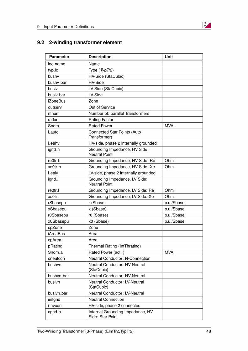
9.2 2-winding transformer element
Parameter Description Unit
loc name Nametyp id Type (TypTr2)bushv HV-Side (StaCubic)bushv bar HV-Sidebuslv LV-Side (StaCubic)buslv bar LV-SideiZoneBus Zoneoutserv Out of Servicentnum Number of: parallel Transformersratfac Rating FactorSnom Rated Power MVAi auto Connected Star Points (Auto
Transformer)i eahv HV-side, phase 2 internally groundedignd h Grounding Impedance, HV Side:
Neutral Pointre0tr h Grounding Impedance, HV Side: Re Ohmxe0tr h Grounding Impedance, HV Side: Xe Ohmi ealv LV-side, phase 2 internally groundedignd l Grounding Impedance, LV Side:
Neutral Pointre0tr l Grounding Impedance, LV Side: Re Ohmxe0tr l Grounding Impedance, LV Side: Xe OhmrSbasepu r (Sbase) p.u./SbasexSbasepu x (Sbase) p.u./Sbaser0Sbasepu r0 (Sbase) p.u./Sbasex0Sbasepu x0 (Sbase) p.u./SbasecpZone ZoneiAreaBus AreacpArea AreapRating Thermal Rating (IntThrating)Snom a Rated Power (act. ) MVAcneutcon Neutral Conductor: N-Connectionbushvn Neutral Conductor: HV-Neutral
(StaCubic)bushvn bar Neutral Conductor: HV-Neutralbuslvn Neutral Conductor: LV-Neutral
(StaCubic)buslvn bar Neutral Conductor: LV-Neutraliintgnd Neutral Connectioni hvcon HV-side, phase 2 connectedcgnd h Internal Grounding Impedance, HV
Side: Star Point
Two-Winding Transformer (3-Phase) (ElmTr2,TypTr2) 48
9 Input Parameter Definitions
Parameter Description Unit
cpeter h Internal Grounding Impedance, HVSide: Petersen Coil
i lvcon LV-side, phase 2 connectedcgnd l Internal Grounding Impedance, LV
Side: Starcpeter l Internal Grounding Impedance, LV
Side: Petersen CoilbSbasepu b (Sbase) p.u.cpCtrlNode Controller, Tap Changer 1: Target
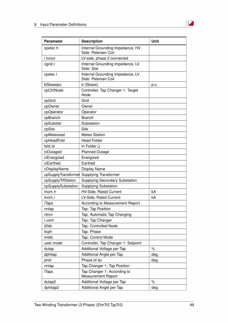
NodecpGrid GridcpOwner OwnercpOperator OperatorcpBranch BranchcpSubstat SubstationcpSite SitecpMeteostat Meteo StationcpHeadFold Head Folderfold id In Folder ()ciOutaged Planned OutageciEnergized EnergizedciEarthed EarthedcDisplayName Display NamecpSupplyTransformer Supplying TransformercpSupplyTrfStation Supplying Secondary SubstationcpSupplySubstation Supplying SubstationInom h HV-Side, Rated Current kAInom l LV-Side, Rated Current kAiTaps According to Measurement Reportnntap Tap: Tap Positionntrcn Tap: Automatic Tap Changingi cont Tap: Tap Changert2ldc Tap: Controlled Nodeilcph Tap: Phaseimldc Tap: Control Modeuset mode Controller, Tap Changer 1: Setpointdutap Additional Voltage per Tap %dphitap Additional Angle per Tap degphitr Phase of du degnntap Tap Changer 1: Tap PositioniTaps Tap Changer 1: According to
Measurement Reportdutap2 Additional Voltage per Tap %dphitap2 Additional Angle per Tap deg
Two-Winding Transformer (3-Phase) (ElmTr2,TypTr2) 49

9 Input Parameter Definitions
Parameter Description Unit
phitr2 Phase of du degnntap2 Tap Changer 2: Tap Positionc ptapc Controller, Tap Changer 1: External
Tap Controllerc pstac Controller, Tap Changer 1: External
Station Controlleri rem Tap: Remote Controlp rem Tap: Controlled Node
(StaBar,ElmTerm)p cub Tap: Controlled Branch (Cubicle)
(StaCubic)usetp Tap: Voltage Setpoint p.u.usp low Tap: Lower Voltage Bound p.u.usp up Tap: Upper Voltage Bound p.u.psetp Tap: Active Power Setpoint MWpsp low Tap: Lower Active Power Bound MWpsp up Tap: Upper Active Power Bound MWqsetp Tap: Reactive Power Setpoint Mvarqsp low Tap: Lower Reactive Power Bound Mvarqsp up Tap: Upper Reactive Power Bound MvarTctrl Tap: Controller Time Constant sKqctrl Controller, Tap Changer 1: Controller
Sensitivity dv/dQ%/Mvar
Kpctrl Controller, Tap Changer 1: ControllerSensitivity dv/dP
%/MW
ildc Tap: Line Drop Compensationldcct Tap: Current Transformer Rating Aldcpt Tap: Voltage Transformer Ratioldcrs Tap: Rset Vldcxs Tap: Xset Vtapctrl Tap Controller (ElmTr2)iMeasLoc Measured atmTaps Measurement Reportiblock Unit Transformerilt op Long-term operating condition before
short-circuit are knownUb lv Values for LV-Side: Highest Operating
VoltagekV
Ib lv Values for LV-Side: Highest OperatingCurrent
kA
cosphib lv Values for LV-Side: Power factorUbqmin hv Values for HV-Side (only for Unit
Transformer): Minimum OperatingVoltage
kV
ifrqft Frequent Fault ( >10(5)/lifetime,Category II(III) )
Two-Winding Transformer (3-Phase) (ElmTr2,TypTr2) 50
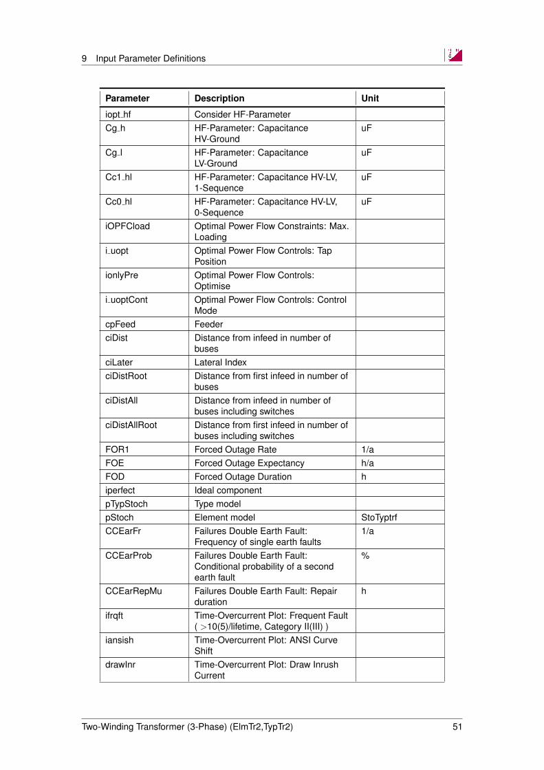
9 Input Parameter Definitions
Parameter Description Unit
iopt hf Consider HF-ParameterCg h HF-Parameter: Capacitance
HV-GrounduF
Cg l HF-Parameter: CapacitanceLV-Ground
uF
Cc1 hl HF-Parameter: Capacitance HV-LV,1-Sequence
uF
Cc0 hl HF-Parameter: Capacitance HV-LV,0-Sequence
uF
iOPFCload Optimal Power Flow Constraints: Max.Loading
i uopt Optimal Power Flow Controls: TapPosition
ionlyPre Optimal Power Flow Controls:Optimise
i uoptCont Optimal Power Flow Controls: ControlMode
cpFeed FeederciDist Distance from infeed in number of
busesciLater Lateral IndexciDistRoot Distance from first infeed in number of
busesciDistAll Distance from infeed in number of
buses including switchesciDistAllRoot Distance from first infeed in number of
buses including switchesFOR1 Forced Outage Rate 1/aFOE Forced Outage Expectancy h/aFOD Forced Outage Duration hiperfect Ideal componentpTypStoch Type modelpStoch Element model StoTyptrfCCEarFr Failures Double Earth Fault:
Frequency of single earth faults1/a
CCEarProb Failures Double Earth Fault:Conditional probability of a secondearth fault
%
CCEarRepMu Failures Double Earth Fault: Repairduration
h
ifrqft Time-Overcurrent Plot: Frequent Fault( >10(5)/lifetime, Category II(III) )
iansish Time-Overcurrent Plot: ANSI CurveShift
drawInr Time-Overcurrent Plot: Draw InrushCurrent
Two-Winding Transformer (3-Phase) (ElmTr2,TypTr2) 51
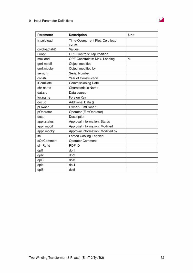
9 Input Parameter Definitions
Parameter Description Unit
fr coldload Time-Overcurrent Plot: Cold loadcurve
coldloadtab2 Valuesi uopt OPF-Controls: Tap Positionmaxload OPF-Constraints: Max. Loading %gnrl modif Object modifiedgnrl modby Object modified bysernum Serial Numberconstr Year of ConstructioniComDate Commissioning Datechr name Characteristic Namedat src Data sourcefor name Foreign Keydoc id Additional Data ()pOwner Owner (ElmOwner)pOperator Operator (ElmOperator)desc Descriptionappr status Approval Information: Statusappr modif Approval Information: Modifiedappr modby Approval Information: Modified byifc Forced Cooling EnabledsOpComment Operator CommentcimRdfId RDF IDdpl1 dpl1dpl2 dpl2dpl3 dpl3dpl4 dpl4dpl5 dpl5
Two-Winding Transformer (3-Phase) (ElmTr2,TypTr2) 52

10 References
10 References
[1] Guidelines for representation of network elements when calculating transients. Technicalreport, Cigre Working Group 33.02, 1990.
[2] Three phase oil-immersed distribution transformers, 50 hz, from 50 to 2500 kva with highestvoltage for equipment not exceeding 36 kv. Determination of the power rating of a trans-former loaded with non-sinusoidal currents, 1995.
[3] IEEE Std c57.110-1998 Recommended Practice for Establishing Transformer Capability,1999.
[4] Allan Greenwood. Electrical Transients in Power Systems. John Wiley & Sons, 1991.
Two-Winding Transformer (3-Phase) (ElmTr2,TypTr2) 53
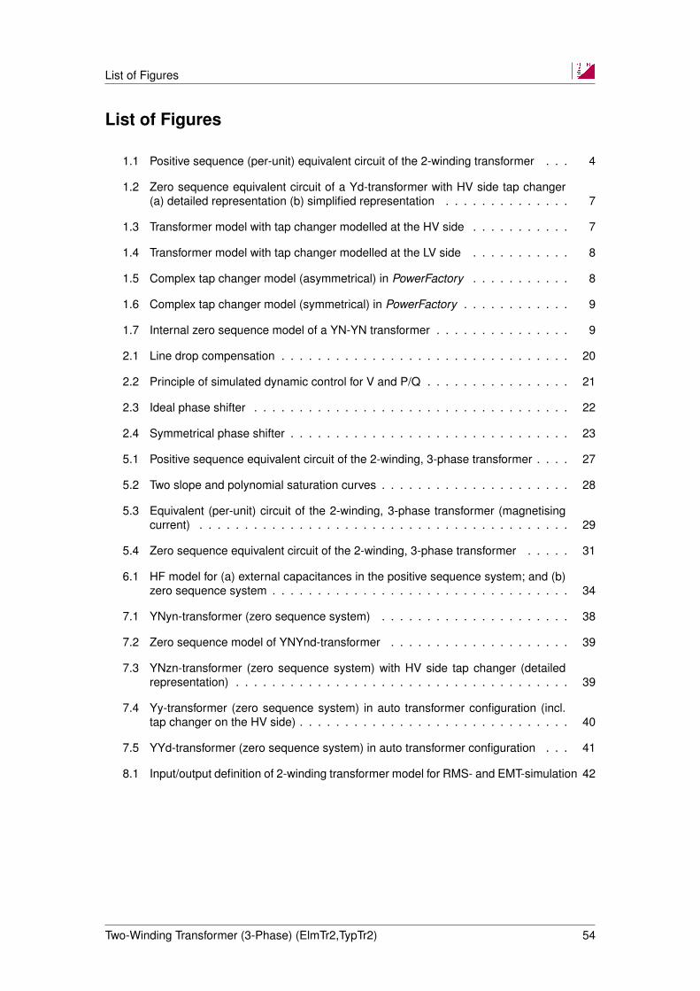
List of Figures
List of Figures
1.1 Positive sequence (per-unit) equivalent circuit of the 2-winding transformer . . . 4
1.2 Zero sequence equivalent circuit of a Yd-transformer with HV side tap changer(a) detailed representation (b) simplified representation . . . . . . . . . . . . . . 7
1.3 Transformer model with tap changer modelled at the HV side . . . . . . . . . . . 7
1.4 Transformer model with tap changer modelled at the LV side . . . . . . . . . . . 8
1.5 Complex tap changer model (asymmetrical) in PowerFactory . . . . . . . . . . . 8
1.6 Complex tap changer model (symmetrical) in PowerFactory . . . . . . . . . . . . 9
1.7 Internal zero sequence model of a YN-YN transformer . . . . . . . . . . . . . . . 9
2.1 Line drop compensation . . . . . . . . . . . . . . . . . . . . . . . . . . . . . . . . 20
2.2 Principle of simulated dynamic control for V and P/Q . . . . . . . . . . . . . . . . 21
2.3 Ideal phase shifter . . . . . . . . . . . . . . . . . . . . . . . . . . . . . . . . . . . 22
2.4 Symmetrical phase shifter . . . . . . . . . . . . . . . . . . . . . . . . . . . . . . . 23
5.1 Positive sequence equivalent circuit of the 2-winding, 3-phase transformer . . . . 27
5.2 Two slope and polynomial saturation curves . . . . . . . . . . . . . . . . . . . . . 28
5.3 Equivalent (per-unit) circuit of the 2-winding, 3-phase transformer (magnetisingcurrent) . . . . . . . . . . . . . . . . . . . . . . . . . . . . . . . . . . . . . . . . . 29
5.4 Zero sequence equivalent circuit of the 2-winding, 3-phase transformer . . . . . 31
6.1 HF model for (a) external capacitances in the positive sequence system; and (b)zero sequence system . . . . . . . . . . . . . . . . . . . . . . . . . . . . . . . . . 34
7.1 YNyn-transformer (zero sequence system) . . . . . . . . . . . . . . . . . . . . . 38
7.2 Zero sequence model of YNYnd-transformer . . . . . . . . . . . . . . . . . . . . 39
7.3 YNzn-transformer (zero sequence system) with HV side tap changer (detailedrepresentation) . . . . . . . . . . . . . . . . . . . . . . . . . . . . . . . . . . . . . 39
7.4 Yy-transformer (zero sequence system) in auto transformer configuration (incl.tap changer on the HV side) . . . . . . . . . . . . . . . . . . . . . . . . . . . . . . 40
7.5 YYd-transformer (zero sequence system) in auto transformer configuration . . . 41
8.1 Input/output definition of 2-winding transformer model for RMS- and EMT-simulation 42
Two-Winding Transformer (3-Phase) (ElmTr2,TypTr2) 54
List of Tables
List of Tables
1.1 Input- and calculation parameters . . . . . . . . . . . . . . . . . . . . . . . . . . . 6
1.2 Type Basic Data: Positive sequence impedance . . . . . . . . . . . . . . . . . . . 13
1.3 Type Basic Data: Zero sequence impedance (no internal delta winding) . . . . . 13
1.4 Type Basic Data: Zero sequence impedance: YN-YN; with internal delta winding 14
2.1 Measurement report data (transformer element) . . . . . . . . . . . . . . . . . . 17
2.2 Automatic tap changer control . . . . . . . . . . . . . . . . . . . . . . . . . . . . . 19
2.3 Line drop compensation (for voltage control) . . . . . . . . . . . . . . . . . . . . . 20
2.4 Dynamic and static control parameters . . . . . . . . . . . . . . . . . . . . . . . . 21
2.5 Load Flow tap changer data . . . . . . . . . . . . . . . . . . . . . . . . . . . . . . 21
2.6 Load Flow Tap dependent impedance data . . . . . . . . . . . . . . . . . . . . . 25
5.1 Two-slope and polynomial saturation characteristic input parameters . . . . . . . 28
8.1 Input variables of RMS and EMT transformer model . . . . . . . . . . . . . . . . 42
8.2 State variables of transformer model for EMT-simulation . . . . . . . . . . . . . . 42
8.3 Additional parameters and signals for EMT transformer model (calculation pa-rameters) . . . . . . . . . . . . . . . . . . . . . . . . . . . . . . . . . . . . . . . . 42
Two-Winding Transformer (3-Phase) (ElmTr2,TypTr2) 55


![TechRef Load[1]](https://static.documents.pub/doc/80x56/54005ab2dab5caaf758b4682/techref-load1.jpg)


