TECHNICAL DOCUMENT FOR DESIGN, ENGINEERING, PROCUREMENT, MANUFACTURE, INSPECTION, TESTING, PACKING & FORWARDING AND SUPPLY OF GAS FIRED INDIRECT WATER BATH HEATER ALONG WITH REQUIRED INSTRUMENTATIONS, CONTROL PANEL ETC. AND INSTALLATION & COMMISSIONING AT GAIL, HAZIRA
AND SUPPLY OF GAS FIRED INDIRECT WATER BATH HEATER ALONG WITH REQUIRED INSTRUMENTATIONS, CONTROL
PANEL ETC. AND
INSTALLATION & COMMISSIONING AT
GAIL, HAZIRA
CHAPTER – 1
INTRODUCTION
1. INTRODUCTION
M/s GAIL (India) Limited is a PSU (A Navratna Company) mainly in the
business of gas transmission to various consumers across India. Hazira
Compressor Station is the gateway station of GAIL’s HVJ Pipeline
Network. The compressor station is at Surat, Gujarat.
For operational requirement, GAIL intends to procure indirect water
bath natural gas fired heater (the details of which are given in the
Tender Document) to be installed at Hazira Compressor Station required
for heating of natural gas being supplied to M/s NTPC, Kawas.
NAME OF THE EQUIPMENT: Skid mounted horizontal and cylindrical gas fired indirect water bath heater with all instrumentations/accessories to complete the system. The indirect fired heater utilizes a water bath, heated by a 'U' tube type firebox, to supply heat to a process coil carrying natural gas, which is also submerged in the water bath. Combustion of natural gas, in the fire tube, heats the water bath. This hot water bath in turn transfers heat to the surface of the process coil, thereby transferring heat to the process gas flowing through the coil. The complete monitoring and control of IDBH is done by locally mounted PLC based Burner Management System.
CAPACITY: Natural Gas Flow of 2.50 MMSCMD/Equivalent Approximate
Heat Load 9 MMBtu per Hour (the heat load is only indicative as per
the process parameters with an assumed efficiency of 65%; however,
the vendor shall calculate the actual heat load while quoting against
the Tender Enquiry by using approved software like HYSIS based on the
gas data given in the Tender Document).
QUANTITY: 01 NUMBER
LOCATION/SITE: GAIL (INDIA) LIMITED, HAZIRA COMPRESSOR STATION, SURAT
AVAILABLE SPACE FOR INSTALLATION OF HEATER: 15 METRES X 4 METRES
CHAPTER – 2
MATERIAL REQUISITION
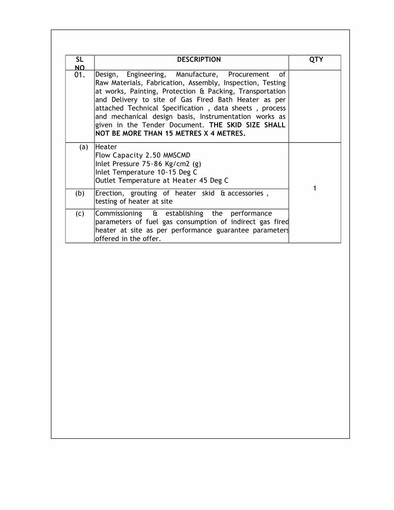
SL
NO DESCRIPTION QTY
01. Design, Engineering, Manufacture, Procurement of
Raw Materials, Fabrication, Assembly, Inspection, Testing
at works, Painting, Protection & Packing, Transportation
and Delivery to site of Gas Fired Bath Heater as per
attached Technical Specification , data sheets , process
and mechanical design basis, Instrumentation works as
given in the Tender Document. THE SKID SIZE SHALL
NOT BE MORE THAN 15 METRES X 4 METRES.
(a) Heater
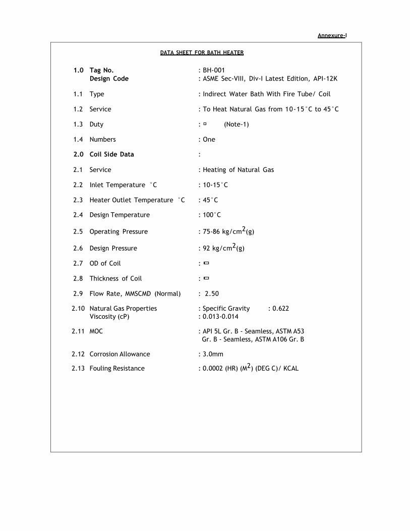
Flow Capacity 2.50 MMSCMD
Inlet Pressure 75-86 Kg/cm2 (g) Inlet Temperature 10-15 Deg C Outlet Temperature at Heater 45 Deg C
1
(b) Erection, grouting of heater skid & accessories , testing of heater at site
(c) Commissioning & establishing the performance
parameters of fuel gas consumption of indirect gas fired
heater at site as per performance guarantee parameters
offered in the offer.
B. REMARKS / COMMENTS
1. GENERAL NOTES
VENDOR's Compliance
Vendor shall submit his bid in full compliance with the requirements of this MR and attachments.
Vendor must include the following statement in his bid:
We certify that our bid is fully complying with your enquiry dated
___________________
Compliance with this material requisition in any instance shall not relieve the Vendor of his responsibility to meet the specified performance.
2. COMPLIANCE WITH SPECIFICATION
The VENDOR shall be completely responsible for the design, materials,
fabrication, testing, inspection, preparation for shipment and transport of the
above equipment strictly in accordance with the Material Requisition and all
attachments thereto.
3. VENDOR'S SCOPE OF SUPPLY & WORK
All items, internals and accessories including those which are not
mentioned but required for satisfactory operation and t esting except
those specifically indicated as outside Vendor's scope are included in their
scope of supply/work.
4. INSPECTION
Inspection shall be performed by a designated/approved Third Party
Inspection Agency and / GAIL, as set out and specified in the codes and
particular documents forming this Material Requisition.
5. APPLICABLE DOCUMENTS
General prescriptions, requirements and information are listed in Technical Specification of this Material Requisition.
6. VENDOR'S DOCUMENTS
Vendor shall supply the documentation as listed under Technical
Specification of this Material Requisition. All documents shall be supplied in
English language.
CHAPTER – 3
DESIGN BASIS – PROCESS
TABLE OF CONTENTS
1.0 SCOPE OF DOCUMENT
2.0 GLOSSARY
3.0 DESIGN CRITERIA
4.0 OPERATING & CONTROL PHILOSOPHY FOR HEATING SYSTEM
5.0 MATERIAL OF CONSTRUCTION
6.0 LIFE OF THE EQUIPMENT
7.0 HAZOP STUDY
8.0 REFERENCE DRAWINGS AND DOCUMENTS
1.0 SCOPE OF DOCUMENT
This design basis covers the process design data, information & criteria
for the design of heating system.
2.0 GLOSSARY
2.1 Shell
The shell is a horizontal vessel which contains the process gas coil, fire tube
and heater bath.
2.2 Process Coil
The fluid to be heated is passed through one or more removable coils
which may be arranged either as a single pass coil, split pass coil or spiral
coil.
2.3 Heater Bath
The indirect heating medium is referred to as the heater bath. Corrosion
inhibitors may be added to water bath. Ethylene glycol may be added to
water bath as anti-freezing agent, to avoid any freezing. Heater bath
transfers the heat supplied by the burner to the process fluid (natural gas)
which is flowing in the process coils.
2.4 Burner System
Firing the heater requires a burner system designed for the specific fuel to be
used and may be either natural or forced draft design. The burner system
includes the firing accessories. Intake flame arrestor and other optional
burner accessories as required.
2.5 Fire tube
Natural gas is normally used as fuel gas to fire the heater through a separate
furnace chamber called fire tube. The fire tube is submerged in the heating
medium / bath, kept in the shell of the heater. The fire tube generally
consists of one or more U-tubes fired at one end and exhausting through
a vertical stack for each U-tube. The fire tube transfer the heat released
by burner to the heating medium / bath which then transfer the heat to the
process fluid (natural gas) through the process coil.
2.6 Intake flame Arrestor
A device placed on the air intake of the fire tube to prevent propagation
of flame from inside the fire tube to the outside atmosphere. It normally
consists of a corrugated aluminium cell mounted in a metal housing, which
attaches to the firebox.
2.7 Stack flame Arrestor
A device placed on the exhaust of the stack to prevent propagation of
flame from inside the fire tube to the outside atmosphere. It normally
consists of a corrugated aluminium or stainless steel cell mounted in a metal
housing, which attaches to the top of the stack.
2.8 Stack Rain Shield
A device attached to the top of the stack to prevent rain from falling
directly into the stack. It may also serve as down draft diverter.
2.9 Expansion Drum
A chamber may be directly connected to the heater shell to permit the shell
to be completely filled with water. It reduces the evaporation loses. Its
capacity should be sufficient to contain the water expansion between
ambient and operating temperatures.
3.0 DESIGN CRITERIA
3.1. Process Design Data
3.1.1 System of Units
The international system of units (SI) also known as the Metric System will be
used. International Gas Union (IGU) has also recommended generalizing the
use of the SI system in all matters to gas and gas facilities.
The following gas compositions shall be considered for design of BATH
HEATER.
Gas Composition In Percent (%)
C1 : 89.9
C2 : 6.43
C3 : 2.2
i-C4 : 0.4
n-C4 : 0.6
i-C5 : 0.014
N2 : 0.46
Total sulphur content : 10 ppm
H2S : 4 ppm
3.1.4 Design Process Data for Gas Heating System
Type : Natural gas fired indirect water bath heater
Number of Gas Heater : 01 (ONE)
Heater Outlet Temperature : 45 degree centigrade
Water Bath Temperature : 85 degree centigrade
Temperature (After PRS downstream) : 25 degree Celsius
4.0 OPERATING & CONTROL PHILOSOPHY FOR HEATING SYSTEM
4.1 Temperature Control System
Temperature transmitters are to be installed at the following locations:
(a) Outlet of heater
(b) Water Bath
(c) Downstream of PRS
The inputs of the transmitters are to be directly fed to the PLC and high select
to be considered as process value for controlling burner management system.
The set point shall be user configurable.
4.2. Operating/Control Philosophy
The Control Philosophy describes function, interface and sequence of operation for each of the Control System Components. The Gas Conditioning Skid PLC and the Burner Management System (BMS) are the systems used to perform these functions. The PLC controls a Human Machine Interface Module (HMI). The HMI is used for control and monitoring the Process. All alarms, shutdowns and process variables transmitted are displayed on the monitor. A control description of each of the major components of the Fuel Gas Conditioning System is described as a part of this Control Philosophy. There are outputs from Process Monitoring. Devices that are hardwired directly to the PLC. These functions will be noted in the Control Philosophy. The Logic Programmed in the PLC is responsible for the safe and efficient operation of the Skid.
Fuel gas tap-off is considered from the natural gas out let from the heater. Before PRS, the gas pressure will be as indicated in MR. Thereafter the arrangement for reduction of pressure for burner gas supply as required for burner ignition shall be in Bidder’s scope .Two fuel gas lines (one pilot and main) have been considered for burners and accordingly fuel gas will be distributed in the burners front as shown in piping & instrumentation. The complete arrangement shall be skid mounted and the double safety factor shall be considered at each stage. Burner Arrangement shall consist of Isolation valves , strainer , Pressure regulators , slam shut valves , pressure safety valves , blow down valves, pressure and temperature gauges. Two individual lines also have self regulating valves of settings about 0.7 (for pilot line) and 1.0 bat g (for main line).The Instruments shall be pneumatically controlled. All the instruments shall be selected suitable for natural gas application as per applicable standards.
The PLC based burners management system has been considered and
accordingly before starting the burners, all pre start permissive are to be
satisfied. Few of the start permissions are stated below:
i) Fuel gas pressure not very low.
ii) Bath water temperature not very high.
iii) Bath water level not very low.
iv) Natural gas outlet temperature not very high.
v) Ignitor transformers available/ input voltage available etc.
If all above permissive are available, a "ready to start" indication will
appear in PLC panel. Then press start PB (push button). Purging of burners
will start and continue for desire time with an indication "system purging".
After purging the system, sequence signal will energise the ignitor
transformers to develop spark in front of the burners gun through spark plug.
Simultaneously, solenoid operated shut down valve (SDV) at pilot line will
open and allow to burn the pilot gas through pilot burners in gas heaters.
The flame scanner or thermocouple (at the burners head) will sense the pilot
flame and open the main valve at the inlet line of main burners with
repeat stop command to ignitor and allow fuel to burn through main burners.
After getting the confirmation of stabilization of main flame in burners
through flame scanner / thermocouple the auto sequence closed signal goes
to SDV of pilot line to stop the pilot burner / flame.
The flow of fuel through main burner is regulated through TCV (temperature
control valve) at the downstream of SDV by temperature controller
(PID control) of PLC as stated earlier.
In case of any maintenance or otherwise requirements the heater can be stopped immediately.
4.3. Interlocks / ESD
Burners will trip with alarms if any of the following condition occurs:
i) Fuel gas pressure very low.
ii) Bath water temperature very high.
iii) Bath water level very low.
iv) Outlet temperature of gas heater very high.
v) Burners flame failure / flame temperature very low (sensing
from thermocouple at the burners head).
vi) 230 V AC /24 V DC failures.
vii) Any other cause as per manufacture standard / recommendations etc.
viii) PLC shall have following features:
i) Trending
ii) Display of Alarm / control with touch screen facility.
ix) Burners will reset / restart manually after recovery of fault /
interlocks of burners / system.
nually by pressing the stop push button.
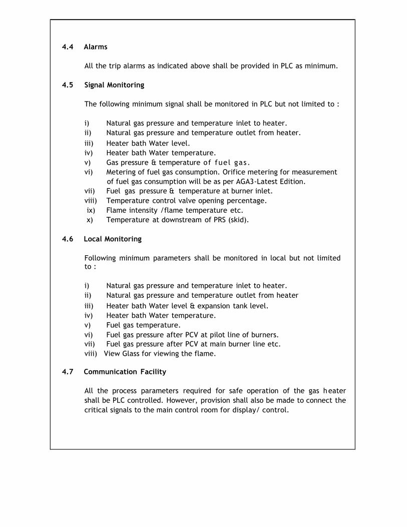
4.4 Alarms
All the trip alarms as indicated above shall be provided in PLC as minimum.
4.5 Signal Monitoring
The following minimum signal shall be monitored in PLC but not limited to :
i) Natural gas pressure and temperature inlet to heater.
ii) Natural gas pressure and temperature outlet from heater.
iii) Heater bath Water level.
iv) Heater bath Water temperature.
v) Gas pressure & temperature of fuel gas .
vi) Metering of fuel gas consumption. Orifice metering for measurement
of fuel gas consumption will be as per AGA3-Latest Edition.
vii) Fuel gas pressure & temperature at burner inlet.
viii) Temperature control valve opening percentage.
ix) Flame intensity /flame temperature etc.
x) Temperature at downstream of PRS (skid).
4.6 Local Monitoring
Following minimum parameters shall be monitored in local but not limited to :
i) Natural gas pressure and temperature inlet to heater.
ii) Natural gas pressure and temperature outlet from heater
iii) Heater bath Water level & expansion tank level.
iv) Heater bath Water temperature.
v) Fuel gas temperature.
vi) Fuel gas pressure after PCV at pilot line of burners.
vii) Fuel gas pressure after PCV at main burner line etc.
viii) View Glass for viewing the flame.
4.7 Communication Facility
All the process parameters required for safe operation of the gas heater
shall be PLC controlled. However, provision shall also be made to connect the
critical signals to the main control room for display/ control.
5.0 MATERIAL OF CONSTRUCTION
Shell Carbon steel conforming ASTM-A-516 GR 60/70
COIL / Pipe Carbon Steel Conforming ASTM A-106 GR B Seamless /
API 5L Gr. B Seamless / ASTM-A-333 GR. 6.
FLANGE ANSI FORGED CARBON STEEL FLANGE
CONFORMING TO ASTM A105/ASTM-A-234 OR WPB.
Fittings MATERIAL TO CONFORM ASTM —A-234 GR. WPB
(Bends. tees)
Bolts/NUTS ASTM-A-193 OR B7 / ASTM-A -194 GR2H.
Chimney / STACKIS-2062
Fire TUBE ASTM-515/516 GR 70 / IS-2002 GR 2.
Expansion TANK/DRUM IS-2062
Corrosion Allowance
Unless & otherwise specified minimum corrosion allowance of 3 mm will
be provided.
Insulation
Hot insulation will be provided on the heater as well as on the out let
gas piping from the heater up to the PRS inlet. (Refer P&ID)
6.0 LIFE OF THE EQUIPMENT
The minimum service life considered for the equipment is 25 years.
7.0 HAZOP STUDY
HAZOP study for the heating system to be carried out upon finalization of the Basic Engineering Package.
8.0 REFERENCE DRAWINGS AND DOCUMENTS P&ID
Refer the P&ID
CHAPTER – 4
DESIGN BASIS – MECHANICAL
TABLE OF CONTENTS
1.0 INTRODUCTION
2.0 PURPOSE
3.0 CODES/ STANDARDS AND DOCUMENTS
4.0 BASIC DATA
5.0 DESIGN OF STATION PIPING AND ASSOCIATED
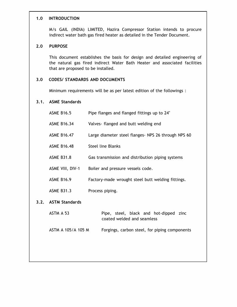
1.0 INTRODUCTION
M/s GAIL (INDIA) LIMITED, Hazira Compressor Station intends to procure
indirect water bath gas fired heater as detailed in the Tender Document.
2.0 PURPOSE
This document establishes the basis for design and detailed engineering of
the natural gas fired indirect Water Bath Heater and associated facilities
that are proposed to be installed.
3.0 CODES/ STANDARDS AND DOCUMENTS
Minimum requirements will be as per latest edition of the followings :
3.1. ASME Standards
ASME B16.5 Pipe flanges and flanged fittings up to 24"
ASME B16.34 Valves- flanged and butt welding end
ASME B16.47 Large diameter steel flanges- NPS 26 through NPS 60
ASME B16.48 Steel line Blanks
ASME B31.8 Gas transmission and distribution piping systems
ASME VIII, DIV-1 Boiler and pressure vessels code.
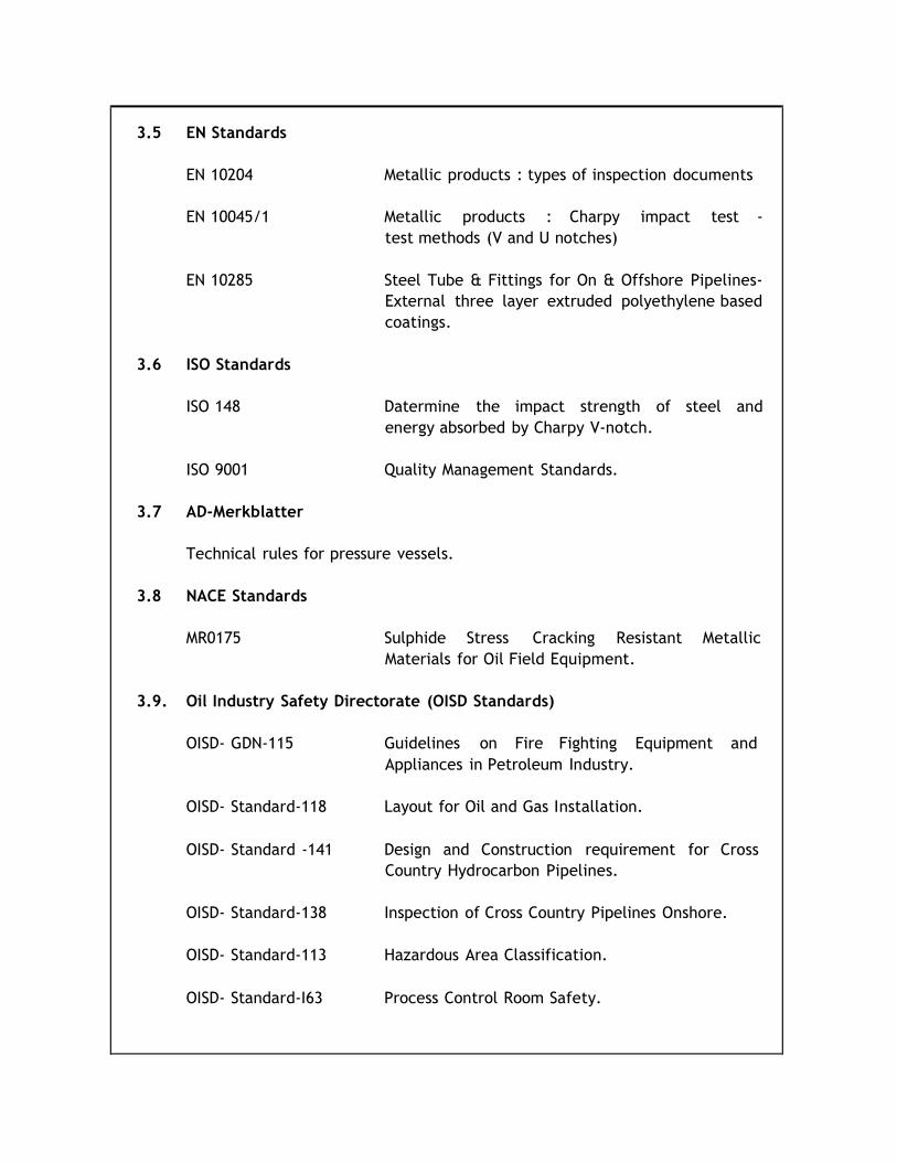
3.9. Oil Industry Safety Directorate (OISD Standards)
OISD- GDN-115 Guidelines on Fire Fighting Equipment and
Appliances in Petroleum Industry.
OISD- Standard-118 Layout for Oil and Gas Installation.
OISD- Standard -141 Design and Construction requirement for Cross
Country Hydrocarbon Pipelines.
OISD- Standard-138 Inspection of Cross Country Pipelines Onshore.
OISD- Standard-113 Hazardous Area Classification.
OISD- Standard-I63 Process Control Room Safety.
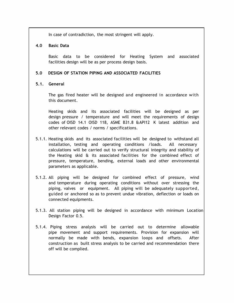
In case of contradiction, the most stringent will apply.
4.0 Basic Data
Basic data to be considered for Heating System and associated
facilities design will be as per process design basis.
5.0 DESIGN OF STATION PIPING AND ASSOCIATED FACILITIES
5.1. General
The gas fired heater will be designed and engineered in accordance with
this document.
Heating skids and its associated facilities will be designed as per
design pressure / temperature and will meet the requirements of design
codes of OISD 14.1 OISD 118, ASME B31.8 & API12 K latest addition and
other relevant codes / norms / specifications.
5.1.1. Heating skids and its associated facilities will be designed to withstand all
installation, testing and operating conditions / loads. All necessary
calculations will be carried out to verify structural integrity and stability of
the Heating skid & its associated facilities for the combined effect of
pressure, temperature, bending, external loads and other environmental
parameters as applicable.
5.1.2. All piping will be designed for combined effect of pressure, wind
and temperature during operating conditions without over stressing the
piping, valves or equipment. All piping will be adequately supported,
guided or anchored so as to prevent undue vibration, deflection or loads on
connected equipments.
5.1.3. All station piping will be designed in accordance with minimum Location
Design Factor 0.5.
5.1.4. Piping stress analysis will be carried out to determine allowable
pipe movement and support requirements. Provision for expansion will
normally be made with bends, expansion loops and offsets. After
construction as built stress analysis to be carried and recommendation there
off will be complied.
5.1.5. Equipment/valves requiring periodical maintenance will be supported in
such a way that the valves and equipment can he removed with a
minimum temporary pipe supports.
5.1.6. Platform crossovers will be provided for ease of operation and
maintenance such that operation could be managed between 0.9 and 1.2 m
height.
5.1.7. Venting facilities will b e p r o v i d e d for a n y e m e r g e n c y
evacuation. Vent line will be fitted with a flapper. Vent shall be 3 m high
from the height of the nearest operating platform.
5.1.8. Pipe leaving the outlet of Heater will be properly insulated in order to
minimize temperature drop of gas.
CHAPTER – 5
SCOPE OF WORK
1. SCOPE OF WORK
The scope of work of the Bidder broadly includes but not limited to the following : Design, engineering, procurement, fabrication, assembly, inspection, testing, painting, insulation, protection & packing, transportation, delivery, unloading at site, erection, performance test & commissioning of the Natural Gas Fired Indirect Water Bath Heater as per Technical Specification as described in this tender document. THE CIVIL FOUNDATION AND HOOK-UP WITH THE INLET & OUTLET 12‖ #600 FLANGES (BATTERY LIMIT) IS IN THE SCOPE OF GAIL.
GENERAL • Supply of Natural Gas Fired indirect water Bath heater which
includes mainly, Heater, Water bath, Process heating coils, Fire Tubes, Burner Management System, Expansion chamber, Vent Stacks, Flame arrestors etc. Supports, platforms & instrumentation and electrical works as necessary etc.
• Design and detailing of components such as Bath Heater,
Heating coils, Burner Management System, Expansion Chamber, Vent Stacks ,Heater assembly / skid, Control panels, instrumentation etc., All type of cables & explosion proof cable glands from the skid to control panel. Surface preparation and painting, Thermal insulation all over equipment, earthing bosses, Name plate and bracket etc.
• HAZOP to be carried out after approval of P&IDs and
recommendations to be incorporated.
• All documentation, drawings calculations and reports as mentioned in Technical Specification – Natural Gas Fired indirect water bath heater.
• Preparation of obtaining approval of GAIL /TPI for QAP of
supply of components & site work / jobs within 21 days of award of order.
• Special Lifting devices, if any for the installation /
commissioning of the heater.
• All consumables and Special maintenance tools & tackles, if applicable.
• Installation and commissioning spares.
• List of spares a long wi th un i t pr ice needed for two years
normal Operation & Maintenance and mandatory spares as recommended by supplier. The same shall not be considered for bid evaluation.
• Vendor to undertake guarantee against failure of
Design, material, performance and workmanship of heating system for 24 month from the date of supply or 12 month from date of commissioning of the equipment whichever is earlier.
• Providing O&M manuals (04 sets) & training to O&M Personnel of
GAIL.
• Obtaining approval of drawings, documents, work procedures
and Quality plan of piping materials, equipment and construction activities from GAIL / TPI.
• Obtaining all statutory permissions from concerned authorities
regarding vent stack height (as per the GPCB Guidelines) with GAIL assistance.
• Obtaining statutory approvals, if required, as per Gujarat Factory
Act.
• Ensuring adequate quality assurance and c o n t r o l including stage w i s e inspection, testing and certification by GAIL’s approved TPI (the TPI will be engaged by the successful bidder).
• Isometric Drawings including "As Built" drawing of entire equipment.
• Civil / Structural design & drawing work of equipment
foundation, pipe support for erection/construction.
• Specific consumption of Natural Gas as indicated by bidder for meeting the Performance.
• Parameters of the heating system as per tender document and
also the same to be guaranteed by the bidder.
• Supplier's representative shall be available at site for 10 days after successful commissioning of heating system.
• Providing suitable lifting arrangement for future ease of maintenance & material handling.
• Providing all access arrangements for case of operation &
maintenance as per the requirement of Owner/Owner's
MECHANICAL
• Procurement of all necessary pipes, valves, fittings & flanges,
gaskets, equipments, etc. required for temporary &
permanent installation and successful completion of above
mentioned job as per relevant technical specifications given in
Tender document. It has to be noted that Owner will not
supply any material.
• Delivery of material at site. Preservation / Protection of
material in good & safe condition. TC (test certificate) of
material supplied to be provided along with or prior to the
supply of material at site.
• Delivery of scaffolding material required for the job. The
supplied scaffolding material shall be inspected by the Owner /
Owner's Representative before using for erection. Contractor
shall use Aluminium ladders only. The erected scaffold shall
require to be approved by Owner/Owner’s representative before
using at site.
• Pre-commissioning (testing, cleaning, drying etc.) and
commissioning (ineritization of heater with N2 then charging of
natural gas in piping system). Procedure for Natural Gas
fired Indirect water Bath Heater and its accessories shall
be submitted by contractor for review of GAIL/TPI representative
prior to commencement of commissioning.
CIVIL
• On placement of LOA, the vendor shall submit the detail civil
foundation drawing for erection of the complete heater along
with its accessories within 30 days. The civil foundation will be in
the scope of GAIL.
INSTRUMENTATION
• For detailed Instrumentation Scope of work – Refer
detail scope under instrumentation head.
PROJECT MANAGEMENT
• Preparation of detailed project schedule.
• Material Management Plan. • QAP (Quality Assurance Plan) duly approved by the TPI.
GUARANTEED PARAMETERS
Bidders are requested to submit thermodynamic calculations to
substantiate the gas consumed for the heater in offer itself.
Price loading for fuel consumption
Bidder shall indicate the total fuel consumption in SCMH as
guaranteed value in the offer. Bidders are requested to indicate the
fuel consumption very carefully as technical loading on bid will be
carried out as per following parameters:
Fuel consumption of all the techno-commercially qualified Bidders
shall be compared with respect to the lowest SCMH quoted by any
Bidder. All other bidders shall be loaded as per differential cost
evaluated as per following formula.
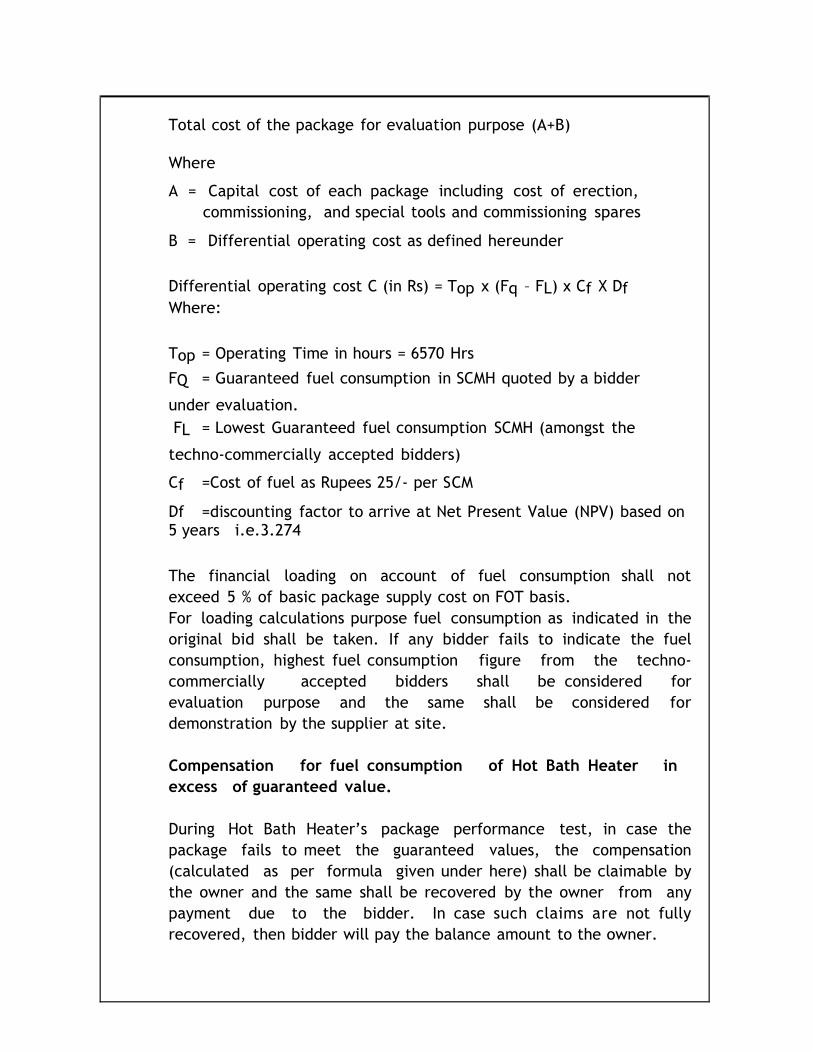
Total cost of the package for evaluation purpose (A+B)
Where
A = Capital cost of each package including cost of erection,
commissioning, and special tools and commissioning spares
B = Differential operating cost as defined hereunder
Differential operating cost C (in Rs) = Top x (Fq – FL) x Cf X Df
Where:
Top = Operating Time in hours = 6570 Hrs
FQ = Guaranteed fuel consumption in SCMH quoted by a bidder
under evaluation.
FL = Lowest Guaranteed fuel consumption SCMH (amongst the
techno-commercially accepted bidders)
Cf =Cost of fuel as Rupees 25/- per SCM
Df =discounting factor to arrive at Net Present Value (NPV) based on 5 years i.e.3.274
The financial loading on account of fuel consumption shall not
exceed 5 % of basic package supply cost on FOT basis.
For loading calculations purpose fuel consumption as indicated in the
original bid shall be taken. If any bidder fails to indicate the fuel
consumption, highest fuel consumption figure from the techno-
commercially accepted bidders shall be considered for
evaluation purpose and the same shall be considered for
demonstration by the supplier at site.
Compensation for fuel consumption of Hot Bath Heater in
excess of guaranteed value.
During Hot Bath Heater’s package performance test, in case the
package fails to meet the guaranteed values, the compensation
(calculated as per formula given under here) shall be claimable by
the owner and the same shall be recovered by the owner from any
payment due to the bidder. In case such claims are not fully
recovered, then bidder will pay the balance amount to the owner.
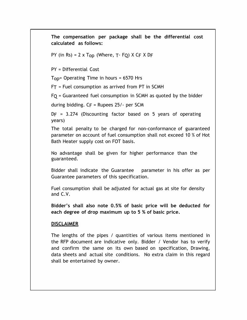
The compensation per package shall be the differential cost
calculated as follows:
PY (in Rs) = 2 x Top (Where, T- FQ) X CF X DF
PY = Differential Cost
Top= Operating Time in hours = 6570 Hrs
FT = Fuel consumption as arrived from PT in SCMH
FQ = Guaranteed fuel consumption in SCMH as quoted by the bidder
during bidding. CF = Rupees 25/- per SCM
DF = 3.274 (Discounting factor based on 5 years of operating
years)
The total penalty to be charged for non-conformance of guaranteed
parameter on account of fuel consumption shall not exceed 10 % of Hot
Bath Heater supply cost on FOT basis.
No advantage shall be given for higher performance than the guaranteed.
Bidder shall indicate the Guarantee parameter in his offer as per
Guarantee parameters of this specification.
Fuel consumption shall be adjusted for actual gas at site for density and C.V.
Bidder’s shall also note 0.5% of basic price will be deducted for
each degree of drop maximum up to 5 % of basic price.
DISCLAIMER
The lengths of the pipes / quantities of various items mentioned in
the RFP document are indicative only. Bidder / Vendor has to verify
and confirm the same on its own based on specification, Drawing,
data sheets and actual site conditions. No extra claim in this regard
shall be entertained by owner.
TECHNICAL SPECIFICATION
FOR
NATURAL GAS FIRED INDIRECT WATER
BATH HEATER
TABLE OF CONTENTS
1. INTRODUCTION
2. SCOPE OF THE DOCUMENT
3. CODES, STANDARDS & LEGAL REQUIREMENTS
3.1. ASME Standards
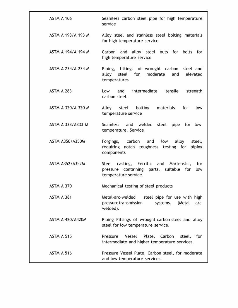
3.2 ASTM Standards
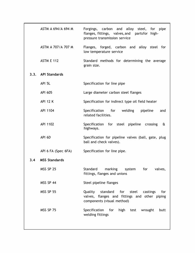
3.3 API Standards
3.4 MSS Standards
3.5 EN Standards
3.6 ISO Standards
3.7 AD-Merkblatter
3.8 NACE Standards
3.9 OIL Industry Safety Directorate (OISD Standards)
4.0 DESIGN DATA
4.1 GAS COMPOSITION
4. 2 INSTRUMENTATION
5.0 BATTERY LIMIT
6.0 BRIEF DESCRIPTION OF NATURAL GAS FIRED INDIRECT WATER BATH HEATERS
7.0 INSTRUMENTATION
8. 0 INSPECTION AND TESTING
9.0 MINIMUM START-UP CRITERIA (CHECKLIST)
10.0 SITE PERFORMANCE GUARANTEE & FUNCTIONAL TEST
11.0 WORKMANSHIP AND GUARANTEE
12.0 PAINTING
13.0 INSULATION
14.0 SPARES
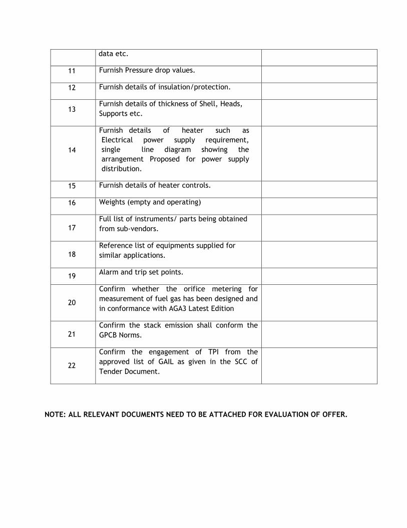
15.0 DATA/DRAWINGS TO BE FURNISHED BY VENDOR
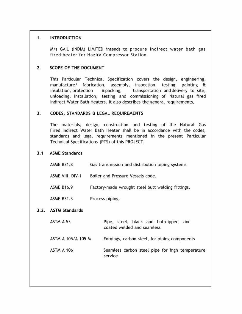
1. INTRODUCTION
M/s GAIL (INDIA) LIMITED intends to procure indirect water bath gas
fired heater for Hazira Compressor Station.
2. SCOPE OF THE DOCUMENT
This Particular Technical Specification covers the design, engineering,
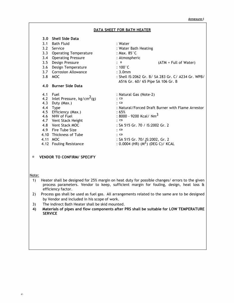
4.4 Type : Natural/Forced Draft Burner with Flame Arrestor 4.5 Efficiency (Max.) : 65% 4.6 NHV of Fuel : 8000 - 9200 Kcal/ Nm3
4.7 Vent Stack Height :
4.8 Vent Stack MOC : SA 515 Gr. 70 / IS:2002 Gr. 2
4.9 Fire Tube Size :
4.10 Thickness of Tube :
4.11 MOC : SA 515 Gr. 70/ IS:2002, Gr. 2 4.12 Fouling Resistance : 0.0004 (HR) (M2) (DEG C)/ KCAL
VENDOR TO CONFIRM/ SPECIFY
Note:
1) Heater shall be designed for 25% margin on heat duty for possible changes/ errors to the given process parameters. Vendor to keep, sufficient margin for fouling, design, heat loss & efficiency factor.
2) Process gas shall be used as fuel gas. All arrangements related to the same are to be designed
by Vendor and included in his scope of work.
3) The indirect Bath Heater shall be skid mounted.
4) Materials of pipes and flow components after PRS shall be suitable for LOW TEMPERATURE SERVICE
CHAPTER – 6
GUIDELINES / SPECIFICATIONS TO BE FOLLOWED FOR INSTRUMENTATION
ITEMS & JOBS
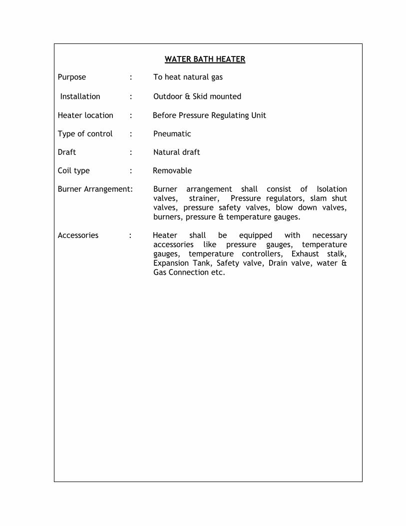
WATER BATH HEATER
Purpose : To heat natural gas
Installation : Outdoor & Skid mounted
Heater location : Before Pressure Regulating Unit
Type of control : Pneumatic
Draft : Natural draft
Coil type : Removable
Burner Arrangement: Burner arrangement shall consist of Isolation
valves, strainer, Pressure regulators, slam shut valves, pressure safety valves, blow down valves, burners, pressure & temperature gauges.
Accessories : Heater shall be equipped with necessary
accessories like pressure gauges, temperature gauges, temperature controllers, Exhaust stalk, Expansion Tank, Safety valve, Drain valve, water & Gas Connection etc.
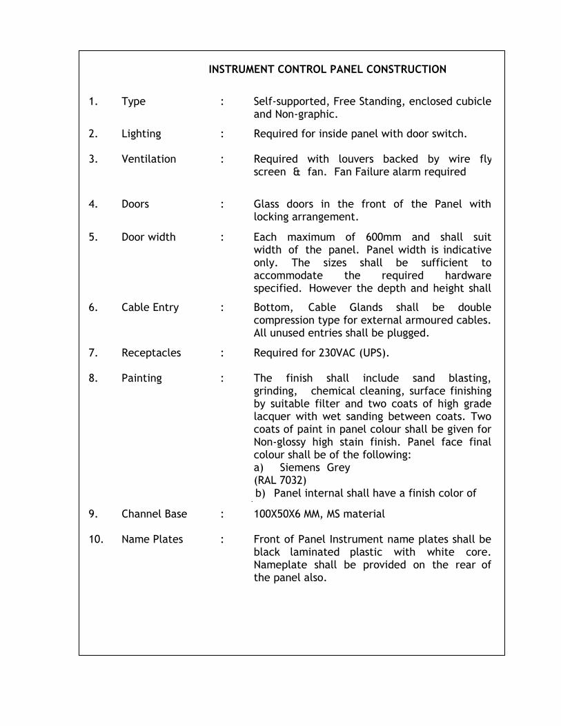
INSTRUMENT CONTROL PANEL CONSTRUCTION
1. Type : Self-supported, Free Standing, enclosed cubicle and Non-graphic.
2.
Lighting :
Required for inside panel with door switch.
3.
Ventilation :
Required with louvers backed by wire fly screen & fan. Fan Failure alarm required
4.
Doors :
Glass doors in the front of the Panel with locking arrangement.
5.
Door width :
Each maximum of 600mm and shall suit width of the panel. Panel width is indicative only. The sizes shall be sufficient to accommodate the required hardware specified. However the depth and height shall be 800 & 2200 respectively.
6.
Cable Entry :
Bottom, Cable Glands shall be double compression type for external armoured cables. All unused entries shall be plugged.
7.
Receptacles :
Required for 230VAC (UPS).
8.
Painting :
The finish shall include sand blasting, grinding, chemical cleaning, surface finishing by suitable filter and two coats of high grade lacquer with wet sanding between coats. Two coats of paint in panel colour shall be given for Non-glossy high stain finish. Panel face final colour shall be of the following: a) Siemens Grey (RAL 7032)
b) Panel internal shall have a finish color of pale cream – IS 352 c) Channel Base shall have a finish color of black
9.
Channel Base :
100X50X6 MM, MS material
10.
Name Plates :
Front of Panel Instrument name plates shall be black laminated plastic with white core. Nameplate shall be provided on the rear of the panel also.
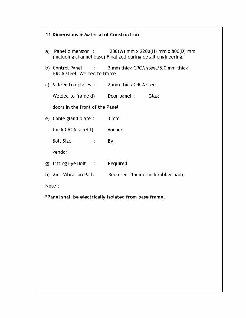
11 Dimensions & Material of Construction a) Panel dimension : 1200(W) mm x 2200(H) mm x 800(D) mm
(Including channel base) Finalized during detail engineering.
b) Control Panel : 3 mm thick CRCA steel/5.0 mm thick
HRCA steel, Welded to frame
c) Side & Top plates : 2 mm thick CRCA steel,
Welded to frame d) Door panel : Glass
doors in the front of the Panel
e) Cable gland plate : 3 mm
thick CRCA steel f) Anchor
Bolt Size : By
vendor
g) Lifting Eye Bolt : Required
h) Anti Vibration Pad : Required (15mm thick rubber pad).
Note :
*Panel shall be electrically isolated from base frame.
1
2
a
)
b
)
WIRING Type : Wiring details 230 VAC UPS Wiring
General purpose, Intrinsically safe
External to Cabinet : Min. 3x2.5 mm²/copper conductor PVC insulated armoured Inside the cabinet : Min. 19 Strands, 16 AWG copper conductor PVC insulated 230 VAC Wiring (Non
Inside the cabinet : Multi stranded min. 1.0 mm² copper conductor PVC insulated twin twisted and shielded.
d)
Terminal type :
Screw clamp type with Pressure Plate
Terminal size for signal :
Suitable for min. 2.5 mm² size conductor Terminal size for power
dist :
Suitable for min. 4.0 mm² size conductor and higher as per actual cable sizes.
Terminal block : Clip-on type
e)
Wiring colour code
Power Supply :
Hot – Red, Neutral - Black, Earth – Green
DC Wiring : Positive – Red, Negative – Black Alarm System : White Control & shutdown : Yellow Analog signals (IS) : Light blue Identification of Cable Termination : Criss – Crossing PVC tube ferruling.
f)
Power Indication Lamps :
230VAC UPS – Red color, 230VAC NUPS – Red Color 24VDC – Green Color
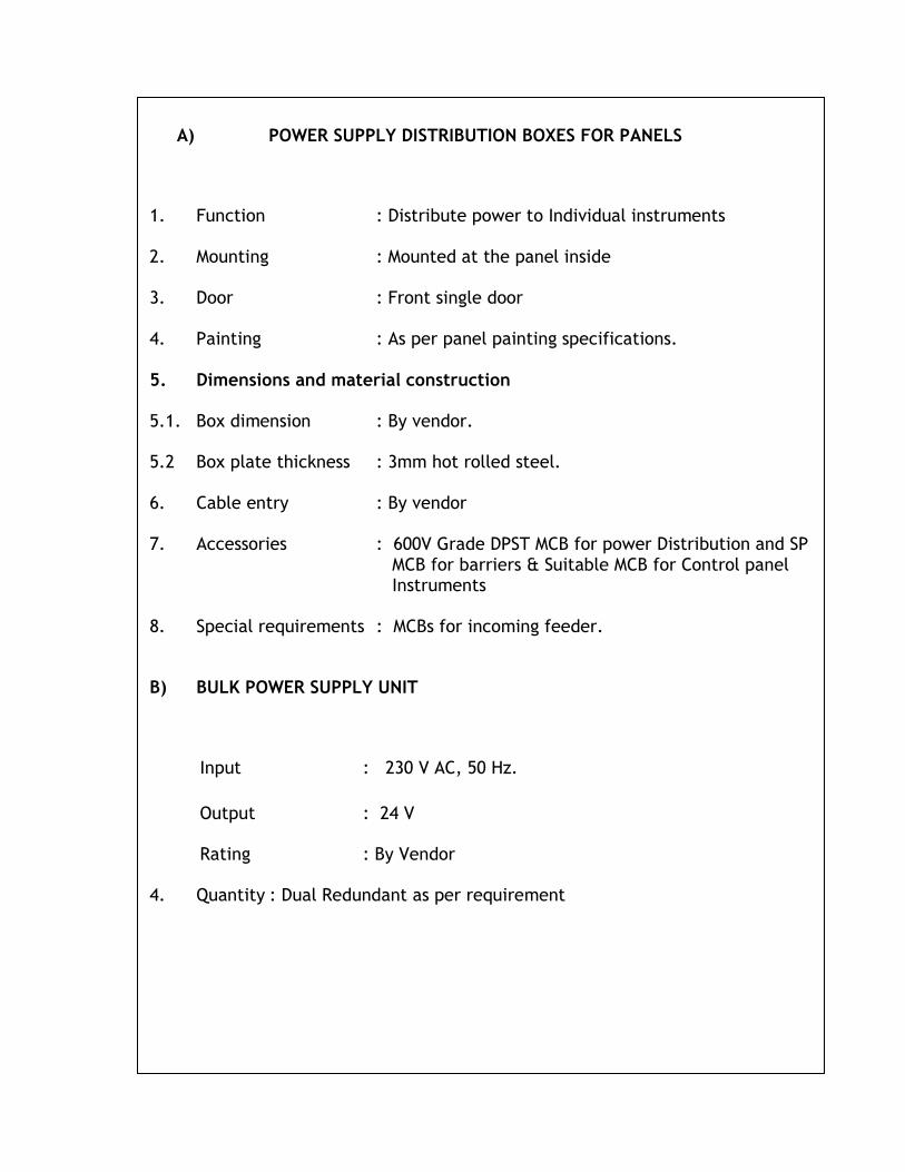
A) POWER SUPPLY DISTRIBUTION BOXES FOR PANELS 1. Function : Distribute power to Individual instruments
2. Mounting : Mounted at the panel inside
3. Door : Front single door
4. Painting : As per panel painting specifications.
5. Dimensions and material construction
5.1. Box dimension : By vendor.
5.2 Box plate thickness : 3mm hot rolled steel.
6. Cable entry : By vendor
7. Accessories : 600V Grade DPST MCB for power Distribution and SP MCB for barriers & Suitable MCB for Control panel Instruments
8. Special requirements : MCBs for incoming feeder. B) BULK POWER SUPPLY UNIT
1.
Input : 230 V AC, 50 Hz.
Output
: 24 V
3.
Rating
: By Vendor
4. Quantity : Dual Redundant as per requirement
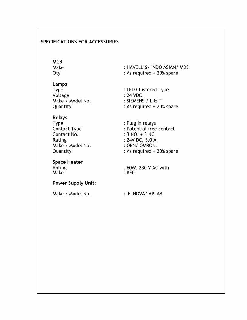
SPECIFICATIONS FOR ACCESSORIES
1.
MCB
Make
: HAVELL’S/ INDO ASIAN/ MDS
Qty : As required + 20% spare
2.
Lamps
Type
: LED Clustered Type
Voltage Make / Model No.
: 24 VDC : SIEMENS / L & T
Quantity : As required + 20% spare
3
Relays
Type
: Plug in relays
Contact Type : Potential free contact Contact No. : 3 NO. + 3 NC Rating : 24V DC, 5.0 A Make / Model No. : OEN/ OMRON. Quantity : As required + 20% spare
4.
Space Heater Rating
: 60W, 230 V AC with Thermostat. Make : KEC
5
Power Supply Unit:
Make / Model No.
: ELNOVA/ APLAB
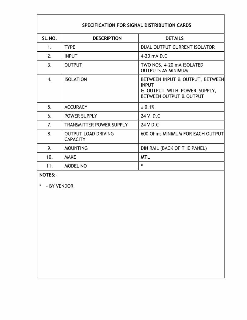
SPECIFICATION FOR SIGNAL DISTRIBUTION CARDS
SL.NO. DESCRIPTION DETAILS
1. TYPE DUAL OUTPUT CURRENT ISOLATOR
2. INPUT 4-20 mA D.C
3. OUTPUT TWO NOS. 4-20 mA ISOLATED OUTPUTS AS MINIMUM
4. ISOLATION BETWEEN INPUT & OUTPUT, BETWEEN INPUT & OUTPUT WITH POWER SUPPLY, BETWEEN OUTPUT & OUTPUT
5. ACCURACY ± 0.1%
6. POWER SUPPLY 24 V D.C
7. TRANSMITTER POWER SUPPLY 24 V D.C
8. OUTPUT LOAD DRIVING CAPACITY
600 Ohms MINIMUM FOR EACH OUTPUT
9. MOUNTING DIN RAIL (BACK OF THE PANEL)
10. MAKE MTL
11. MODEL NO *
NOTES:-
* - BY VENDOR
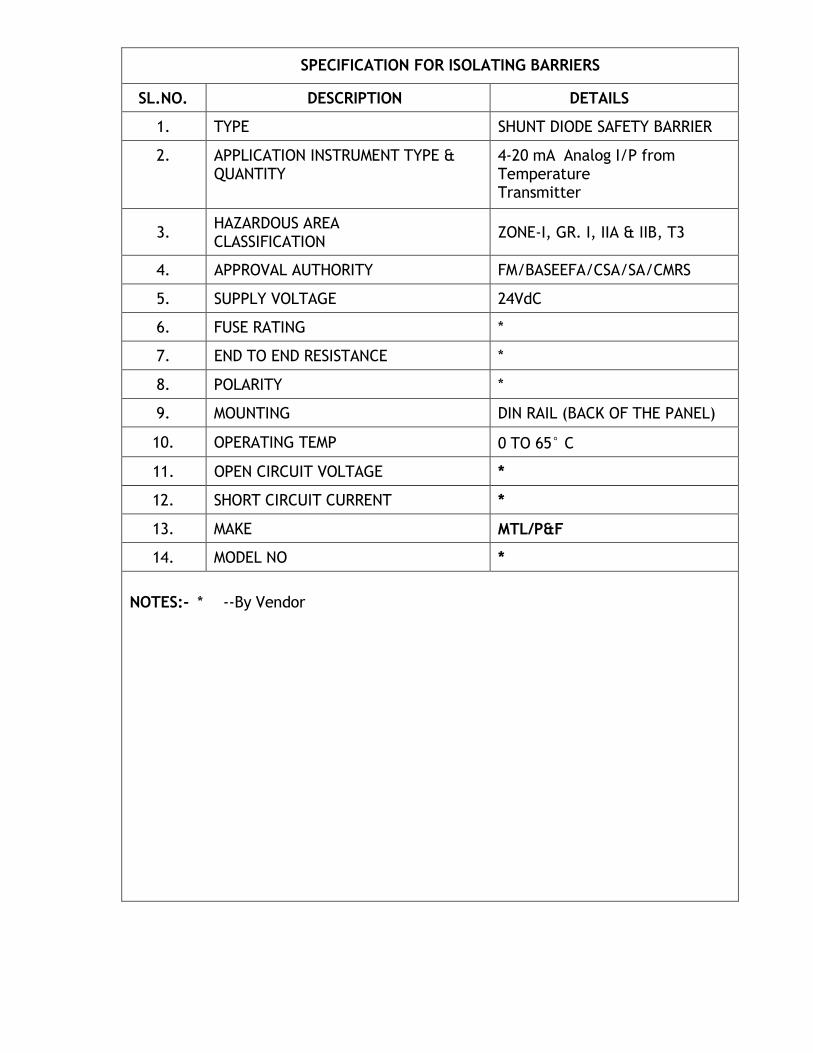
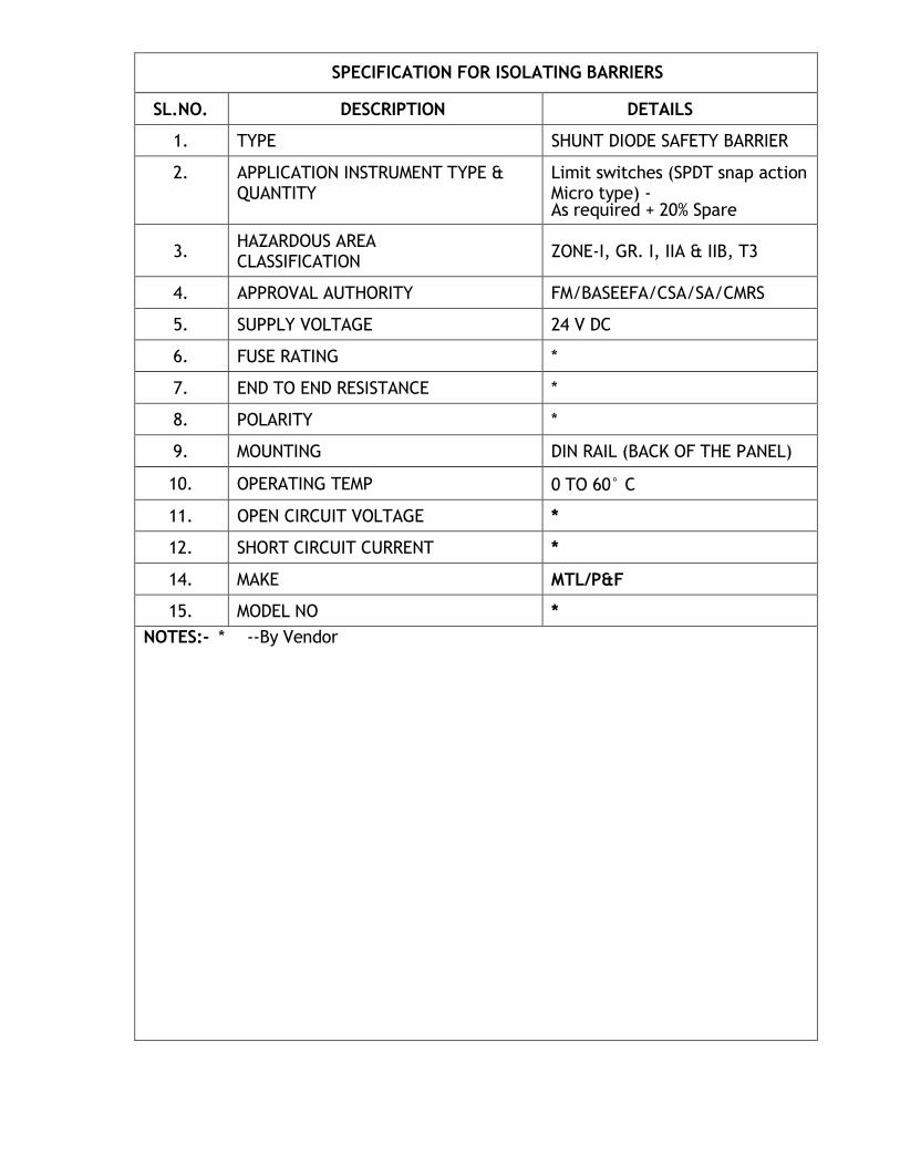
SPECIFICATION FOR ISOLATING BARRIERS
SL.NO. DESCRIPTION DETAILS
1. TYPE SHUNT DIODE SAFETY BARRIER
2. APPLICATION INSTRUMENT TYPE & QUANTITY
(i) 4-20 mA Analog I/P from 2 wire transmitter– As required + 20% Spare
(ii) 4-20 mA Analog O/P to I/P Converter – As required +20% Spare
All the process parameters of the skid shall be provided in the Human Machine Interface Station Computer. The operating system of HMI shall be window based. The computer system for the HMI shall be industrial type IBM compatible, suitable for continuous operation in the non-air-condition environment. It will be mounted in the control panel. The system shall be supplied complete with keyboard, Panel Mounted 17" industrial grade LCD monitor, pointing device, hub, signal converter (RS 485-232 or vice-versa), all accessories, cables, Connectors and laser Printer with 1000 A4 size plain white paper. Licensed version (in name of ―CLIENT‖) of all the required software to be installed and supplied with the HMI. The HMI shall be capable to provide read only data to consumer through serial communication and shall be web enabled. The computer shall be capable for generating Reports, Audit trail, current and historical trend for the process variables. It should have facility of Process data, Alarm manager, Diagnostic Manager (Automatic Verification), Configuration log, Audit trail etc.
Online validation software with license shall be supplied and shall be installed in HMI. Validation software shall be compatible with supplied front end software of HMI and shall be suitable for the application.
HMI shall be designed to work in non air conditioned environment and shall be panel mounted (supplied by bidder). It shall be suitable for environmental conditions mentioned elsewhere.
The computer of HMI shall have hardware with latest configuration and shall have minimum specification of 1GHZ Pentium IV Processor with high resolution SVGA Monitor with 17‖ LCD screen, 512 MB RAM, R/W CD ROM Drive. The monitor shall have high speed refresh rates, 1280 X 1024 pixels and 256 basic distinct colours. The monitor shall be anti-glare, anti-reflective and anti-static. No obsolete hardware shall be supplied.
The HMI software shall be a internationally renowned standard Softwares like wonderware, IFIX, Intellution, cimplicity, licensed in the name of CLIENT. The supplied software shall be Full version (not the run time version) so that it can be upgraded and future changes can be made, if required. All the hardware required to meet the functionality shall be installed in a Control panel.
HMI as a minimum shall contain the following:
a) Display of all the major equipments (indicated in P&ID) along with its Status
indication in dynamic body colour (depending on change in the status, body colour of equipments shall change).
b) Display of all analog parameter-values shall also be provided.
c) The screenshots shall also have feature of display of current/ historical
trends, History, Audit trail, Reports etc.
SPECIFICATION
FOR
JUNCTION BOXES AND CABLE GLANDS
C O N T E N T S
1.0 GENERAL
2.0 JUNCTION BOXES
3.0 CABLE GLANDS & PLUGS, REDUCERS/ ADAPTORS
4.0 NAME PLATE
5.0 SHIPPING
6.0 REJECTION
1.0 General
1.1 Scope
1.1.1 This standard specifications, together with the data sheets attached
herewith, covers the requirements for the design, materials,
nameplate marking, testing and shifting of junction boxes & cable
glands which include the following types:
a) Electrical junction boxes.
b) Pneumatic junction boxes
c) Cable glands (whenever specified)
1.1.2 The related standards referred to herein and mentioned below shall
be of the latest editions prior to the date of the purchaser's enquiry:
ANSI B 2.1 : Pipe threads
IS-5 : Colours for ready mixed paints and enamels
IS-2147 : Degrees of protection provided by enclosures for Low
voltage switchgear and control gear.
IS-2148 : Flame proof enclosure of electrical apparatus.
1.1.3 In the event of any conflict between specifications, data
sheets, related standards, codes etc., the vendor shall refer the
matter to the purchaser for clarifications and only after obtaining the
same should proceed with the manufacture of the items in questions.
1.2 Bids
1.2.1 Vendor's quotation shall include a detailed specification sheet for
each type of junction box and cable gland which shall provide the
following information:
a) All details regarding the t ype, construction, materials, housing,
entries, etc.
b) All dimensions in millimetre.
c) Sketch for each type of JB with dimensional details showing the
terminal and entries arrangement. d) Mounting details. e) Vendor shall furnish certificate from statutory body for
explosion proof enclosure, indicating the gas group and
temperature class.
1.2.2 All the material specifications for various parts in the vendor's
specification sheets shall be to the same standards as those in
purchaser's data sheets (e.g. BS IS, etc.)
1.2.3 Vendor shall attach a list of items, tag number wise, summing
up all the deviations from the purchaser's data sheets, if there are
any. Also vendor shall furnish reasons for these deviations.
and other information for each type of JB/cable glands and its
accessories covered in the bid.
1.2.5 Vendor's quotation, catalogues, drawings, etc. shall be in English language.
1.3 Drawings, Data and Certification
1.3.1 Detailed drawings, data, catalogues required from the vendor are
indicated in vendor data requirements sheets. The required number of
reproducible and prints shall be despatched to the address mentioned,
adhering to the time limits indicated.
1.3.2 After placement of purchaser order, vendor shall submit certified
drawings and specifications sheets for each type of JB/cable gland
which shall include the following:
a) Detailed dimensional drawings
b) Weight of each in grams/Kg.
c) Certificate from statutory body suitable for installation in
specified hazardous area.
2.1 Junction Boxes
2.0 Junction boxes shall be either of the following type as specified in data
sheets.
I. Weather proof junction boxes.
II. Weather proof & Explosion proof junction boxes.
2.2 The enclosure shall be as per IS-2147 for weather proof junction boxes
and for Explosion proof it shall be as per IS-2148 suitable for the area
classification specified.
2.3 Number of entries and locations shall be as per data sheets.
2.4 Junction boxes shall be provided with telephone sockets and
plugs for connection of hand powered telephone set.
2.5 Electrical Junction boxes
2.5.1 Material shall be die-cast aluminium of minimum 5 mm thick (LM-6 alloy)
2.5.2 Explosion proof junction boxes shall have detachable cover which is
fixed to the box by means of cadmium plated triangular
head/hexagonal head screws.
2.5.3 Weather proof junction boxes shall have doors which shall be hinged
type and these shall be fixed with cadmium plated countersunk screws.
2.5.4 Explosion proof junction boxes shall have a warning
engraved/integrally cast on the cover as given below:
"Isolate power supply elsewhere before opening"
2.5.5 Terminals shall be spring loaded, vibration proof, clip-on type, mounted
on nickel plated steel rails complete with end cover and clamps for
each row.
2.5.6 All terminals sha l l be suitable for accepting min imum 2.5 sq.
mm copper conductor, in general. However for power supply
distribution boxes, terminal detail shall be as per job specification/Data
sheets.
2.5.7 Sizing shall be done with due consideration for accessibility and
maintenance in accordance with the following guidelines.
i) 50 to 60 mm between terminals and sides of box parallel to
terminal strip for up to 50 terminals and additional 25mm for
each additional 25 terminals.
ii) 100 to 120mm between terminals for up to 50 terminals and additional 25mm for each additional 25 terminals.
iii) Bottom/top of terminal shall not be less than 100 mm from
bottom/top of the junction box.
2.5.8 Terminals shall be marked as per the various types indicated in data
sheets.
2.5.9 Shall be provided with external earthing lugs.
2.6 Pneumatic junction boxes
2.6.1 Pneumatic junction boxes shall be made of 3mm thick hot rolled
steel. They shall have necessary neoprene gasket between door and
body. Door shall be flush with the box and shall be hinged type and
provided with wing nuts.
2.6.2 Single tube entries shall be suitable for 6mm O.D. copper tube with
bulk head fittings. Multi tube bundle entry shall be suitable for the
data furnished in data sheets.
2.7 Painting
2.7.1 Surface shall be prepared for painting. It shall be smooth and devoid of
rust and scale.
2.7.2 Two coats of lead-free base primer and two final coats of lead free
epoxy based paint shall be applied both for interior and exterior
surfaces.
2.7.3 The colour shall be as specified in data sheets.
3.0 Cable glands & plugs, Reducers/Adaptors
3.1 Cable glands shall be supplied by vendor whenever specified.
3.2 Cable glands shall be double compression type for use with armoured
cables.
3.3 The cable glands shall be of Nickel plated brass.
3.4 The cable gland shall be weather proof. Whenever specified they
shall be explosion proof and certificate from statutory body shall be
furnished.
3.5 Cable glands shall be supplied to suit the cable dimensions indicated
along with tolerance indicated in data sheets. Various components like
rubber ring, metallic ring, metallic cone and the outer/inner nuts etc.
shall be capable of adjusting to the above tolerances of cable
dimensions.
3.6 Reducers/Adaptors shall be supplied as per details indicated in data
sheets. They shall be nickel plated brass. These shall be weather proof in general. These shall also be explosion proof wherever specified and certificate from statutory body for explosion shall be furnished.
3.7 Plugs shall be provided wherever specified. They shall be of Nickel
plated brass.
3.8 Plugs shall be certified explosion proof when used with explosion and
junction boxes.
4.0 Name Plate
4.1 Each junction box shall have an anodised aluminium name plate
permanently fixed to it at a visible place bearing the tag number &
enclosure. The name plate shall also bear the stamp of certifying
agency with certificate number.
5.0 Shipping
5.1 All threaded openings shall be suitably protected to prevent entry of
foreign material.
5.2 All threaded components shall be protected with plastic caps to
prevent damage of threads.
6.0 Rejection
Vendor shall furnish his offer in detail, with respect to every
item of the purchaser's specifications. Any offer not conforming to this
shall be summararily rejected.
SPECIFICATION
FOR SIGNAL CABLES
CO N T E N T S
1.0 GENERAL
2.0 CONSTRUCTION
3.0 ELECTRICAL CHARACTERISTICS
4.0 TESTING
1.0 GENERAL
1.1 Scope:
This specification together with the job Specifications attached
herewith forms the requirements for design, materials manufacturing,
testing and shipping of PVC insulated signal cables.
1.2 Standards:
The cables shall conform to the latest editions of the various
standards mentioned in the specification.
In case of any conflict between any standard and this - specifications
the matter shall be referred to the purchaser before proceeding with
the manufacture of the cables.
1.3 Bids:
1.3.1 Vendor's quotation shall include the following as a minimum.
Completed job spec. Pair identification method, type test certificates,
technical literatures, various testing methods and cross sectional
dimensional drawings. All information/data shall be in English language.
1.3.2 Vendor’s quotation shall include a list of deviations if any from
purchaser’s specifications and shall also indicate the reasons for such
deviations for consideration to arrive at mutually agreed deviations.
However vendor shall note that no deviation shall be accepted in
respect of the permissible limits of resistance capacitance and L/R ratio
of cables.
1.3.3 Vendor shall quote unit price per metre for each type of cable.
1.4 Instructions to Bidder:
1.4.1 The quantity indicated against each type of cable in the job
specification may vary by+_ 25% at the time of placement of order.
Vendor shall confirm that there shall be no price implication on this
account in unit prices type wise.
1.4.2 Drum length for each type of cable shall be 500 to 1000 metres.
Vendor shall indicate the maximum drum length possible for each
type of cable in his bid. Exact requirements of drum length will be
specified after purchase order during detailed engineering and vendor
shall confirm that the same shall not affect the price or delivery
schedule. The actual produced drum length shall not vary by more
than+_ 5% from the value indicated in the purchase order.
1.4.3 Tolerance over the total ordered length shall be as follows:
± 5% for total length less than 5 km
± 2% for total length 5 km or more
1.4.4 Cable dimensions furnished by vendor in his bid shall be firm.
Vendor shall comply with all the values during execution.
1.5 All cables shall be suitable for laying in open air, corrosive
hydrocarbon plant atmosphere, direct sun and in trenches. The cable
shall also be designed for prolonged use in tropical atmosphere.
1.6 On demand vendor shall furnish documents such as invoice and test
certificates to prove the quality and composition of the materials used
for manufacturing the cable to the satisfaction of client/ consultant or
authorised representative during various stages of expediting and
inspection.
2.0 Construction:
2.1 Type 1
(Single pair/triad shielded cable)
2.1.1 Each core shall be 1.5 sq. mm made of 7 stranded annealed electrolytic
copper conductors. Each strand shall be 0.53 mm dia.
2.1.2 Primary insulation shall be 85oC polyvinyl chloride (PVC) as per IS-5831 Type C. Thickness shall be 0.5 mm minimum.
2.1.3 Each wire shall have twisted cores and No. of twists shall be not less
than 10 per metre. Colour of cores insulation shall be black blue in a
pair and black, blue and brown in a triad.
2.1.4 Individual pair and triad shall be shielded. Shield shall be Aluminium
backed by Mylar/polyester tape bonded together with the metallic
side down helically applied with either side - 25% overlap and 100%
coverage. Minimum shielded thickness shall be 0.05mm. Drain wire
shall be 0.5 sq.mm multistrand bare tinned annealed copy conductor.
The drain wire shall be in continuous contact with Aluminium side of the
shield.
2.1.5 Inner and outer jacket shall be made of extruded flame retardant 90oC PVC to IS 5831-Type ST2 Oxygen index of PVC shall be 30. Temp. Index shall be over 250o C. Inner jacket colour shall be black. Outer jacket colour shall be black except for cable to be used in intrinsically safe systems it shall be light blue.
2.1.6 Armour over inner jacket shall be of galvanised steel wire/flat as per
IS-1554 part-I.
2.1.7 A pair or triad identification shall be with numbers at interval of not more than
250 mm as per vendor's standard.
2.1.8 Tolerance in overall diameter of cable shall be within +_ 2mm
over offered value for cables with OD less than 30mm and+3mm for
cables with OD more than 30mm.
2.2 Type-II
(Multipair / Multitraid cable with individual pair shield and overall shield)
The cable shall be same as single pair shielded cable except
conductor size shall be 0.5 sq.mm made of 16 strands of annealed
electrolytic copper conductor. Each strand shall be of 0.2mm dia.
Additional feature shall be as follows:
2.2.1 Overall shield shall be of Aluminium backed up by Mylar/polyester tape
helically applied with the metallic side down either side - 25%
overlap and 100% coverage. Minimum shield thickness shall be
0.075mm Drain wire shall be similar to individual pair drain wire and
shall be in continuous contact with the Aluminium side of the overall
shield.
2.2.2 Overall twist of all pair/triads shall be as per vendor's standard.
2.2.3 A pair of communication wire shall be provided for multipair/multitriad
cables.Each wire shall be 0.5 sq. mm of plain annealed single or multistrand copper conductor with 0.4 mm thick 85oC PVC insulation. Insulation shall be green and red colour coded.
2.3 Type-III
(Multipair/Multitriad cable with only overall shield)
These cables shall be same as type-II cables except that the individual
pair/triad shall not have shielding.
2.4 Type-IV
(Multipair/ multitriad cable with individual pair shield and overall shield)
The cable shall be same as Type II except conductor size shall be 1.5
sq.mm made of 7 stranded annealed electrolytic copper conductor.
Each strand shall be 0.53 mm dia.
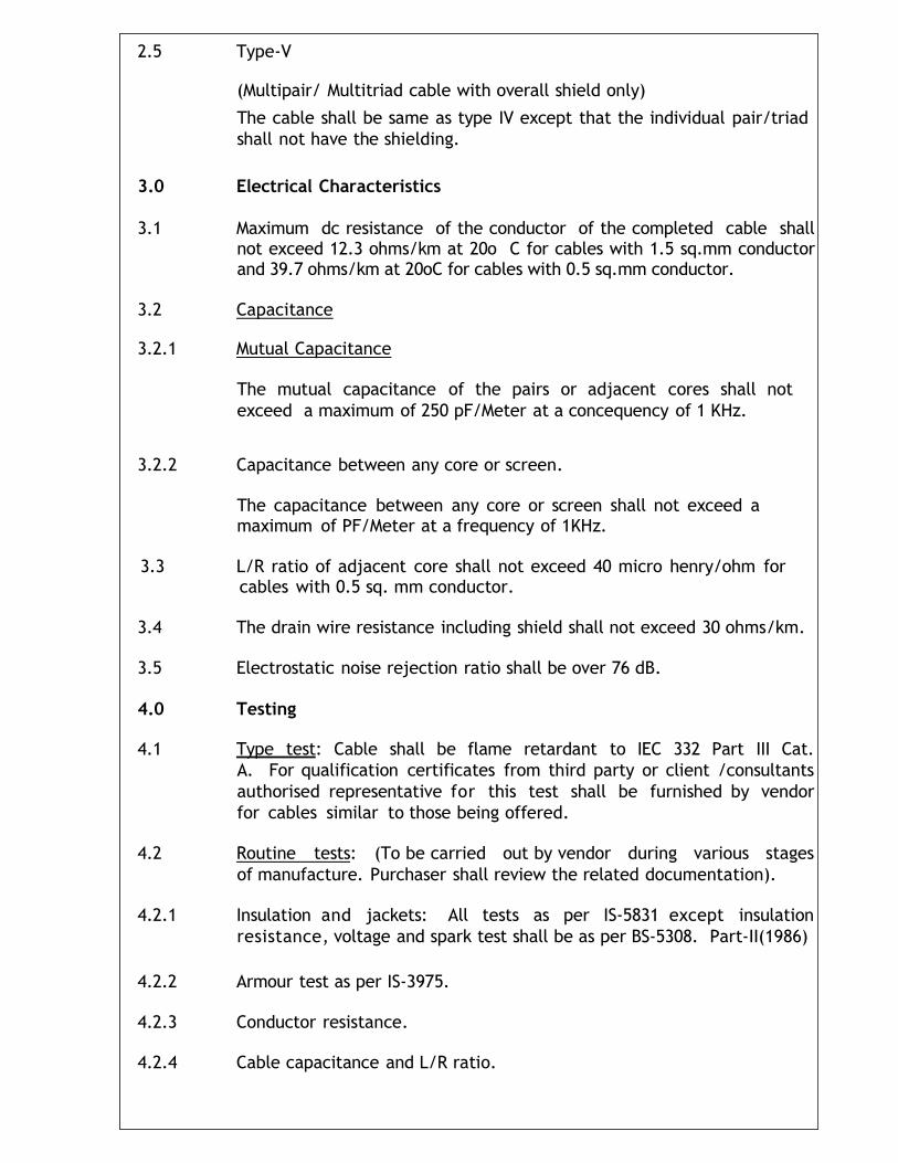
2.5 Type-V
(Multipair/ Multitriad cable with overall shield only)
The cable shall be same as type IV except that the individual pair/triad
shall not have the shielding.
3.0 Electrical Characteristics
3.1 Maximum dc resistance of the conductor of the completed cable shall
not exceed 12.3 ohms/km at 20o C for cables with 1.5 sq.mm conductor and 39.7 ohms/km at 20oC for cables with 0.5 sq.mm conductor.
3.2 Capacitance
3.2.1 Mutual Capacitance
The mutual capacitance of the pairs or adjacent cores shall not
exceed a maximum of 250 pF/Meter at a concequency of 1 KHz.
3.2.2 Capacitance between any core or screen.
The capacitance between any core or screen shall not exceed a maximum of PF/Meter at a frequency of 1KHz.
3.3 L/R ratio of adjacent core shall not exceed 40 micro henry/ohm for
cables with 0.5 sq. mm conductor.
3.4 The drain wire resistance including shield shall not exceed 30 ohms/km.
3.5 Electrostatic noise rejection ratio shall be over 76 dB.
4.0 Testing
4.1 Type test: Cable shall be flame retardant to IEC 332 Part III Cat.
A. For qualification certificates from third party or client /consultants
authorised representative for this test shall be furnished by vendor
for cables similar to those being offered.
4.2 Routine tests: (To be carried out by vendor during various stages
of manufacture. Purchaser shall review the related documentation).
4.2.1 Insulation and jackets: All tests as per IS-5831 except insulation
resistance, voltage and spark test shall be as per BS-5308. Part-II(1986)
4.2.2 Armour test as per IS-3975.
4.2.3 Conductor resistance.
4.2.4 Cable capacitance and L/R ratio.
STANDARD SPECIFICATION
FOR
CABLING
C O N T E N T S
1.0 SCOPE
2.0 STANDARD
3.0 CABLE SPECIFICATIONS
4.0 MISCELLANEOUS MATERIALS SPECIFICATIONS
5.0 CABLE LAYING
6.0 TERMINATION
7.0 TESTING
1.0 SCOPE
This is to define the requirements for supply, wherever applicable,
the installation, testing and commissioning of the cabling system.
2.0 STANDARDS
The work shall be carried out in the best workman like manner in
conformity with this specification, the relevant specifications, codes of
p r a c t i c e o f I n d i a n Standards Institution, approved drawings and
instructions of Engineer-in-Charge or his authorized representative
issued from time to time. In case of any conflict between the standards,
the instruction of Engineer-in-Charge shall be binding.
3.0 CABLE SPECIFICATIONS
3.1 Power Cables
Power cables for use on 415 V systems shall be of 1100 Volts grade,
and overall PVC sheathed. Power cables for 3.3 KV 6.6 KV and
11 KV system shall be aluminium conductor, XLPL insulated, screened,
PVC bedded galvanized steel flat armoured and PVC sheathed cable. All
L.T. Cables conform to standard specification and relevant sections of IS:
1554 Part-I and H.T. Cables shall conform to IS: 7098 (Part II).
Unarmoured cables will be used wherever specified on the cable schedule.
3.2 Control Cables:
Control cables shall be 1100 Volt Grade, 2.5 mm2 copper
conductor PVC insulated PVC sheathed, single wire armoured with an
overall PVC sheath, as per IS: 1554 Pt. Unarmoured cables shall be
used wherever specified on the cable schedule.
3.3 Communication cables:
Communication cables shall comprise 1 pair unarmoured, 2-pair, 5-
pair and multipair armoured cables of sizes as specified in the cable
schedule. Minimum conductor size shall be 0.5 mm telephone system
and 0.71 for plant communication system.
4.0 MISCELLANEOUS MATERIALS SPECIFICATIONS
4.1 Connectors:
Cable terminations shall be made with aluminium / tinned copper
crimped type solder less lugs of M/s. Dowell’s make or approved
equivalent for all aluminium conductors and stud type terminals.
4.2 Cable Identification
Cable tags shall be of 2 mm thick, 20 mm wide aluminium strap of
suitable length to contain cable number, equipment no., etc.
4.3 Ferrules
Ferrules shall be of approved type size to suit core size mentioned and
shall be employed to designate the various cores of control cable
by the terminal numbers to which the cores are connected for case in
identification and maintenance.
4.4 Cable Glands:
Cable glands to be supplied shall be nickel-plated Brass double
compression type of approved/ reputed make. Glands for classified
hazardous areas shall be certified by CMRS.
4.5 Cable Trays:
This shall be either prefabricated hot dip galvanized sheet steel trays or
site fabricated angle iron trays as specified elsewhere. Prefabricated
hot dip galvanized sheet steel cable trays shall be used for maximum
support span of 2000 mm unless design is approved for larger span. For
requirements of larger than 750 mm width two trays shall be run side by
side. Cable trays shall be suitable for a cable weight of 50 kg/meter
running length of tray. Minimum thickness of sheet steel/galvanizing shall
be 2mm/86 microns respectively.
Cable trays fabricated from standard rolled sections shall use 50x50x6 /ISMC 100 Sections for runners for supporting spans limited to 2000 mm/more than 2000 mm respectively. Cross support shall be 32 x 6 mm flat/ 25x25x6 angle for width up to 500 mm/ more than 500 mm respectively.
Vertical supports for both the above type of trays shall be
fabricated out of ISMC 100 and horizontal supports with 75 x 50 x 6
angle iron/ ISMC 75 as approved by Engineer-in-Charge. If unit rate is not included in schedule of rates, then cable trays if required, shall be fabricated and installed at site as per tone rate for electrical structural supports etc.
5.0 CABLE LAYING
5.1 Cable network shall include power, control, lighting and
communication cables, which shall be laid in trenches, cable trays or
conduits as detailed in the relevant drawings and cable schedules.
Erection of cable trays as required shall be checked after erection
and marked in as built drawings. Cable routing given on the layout
drawings shall be checked in the field to avoid interference with
structures, heat sources, drains, piping, air-conditioning duct etc. and
minor adjustments shall be done to suit the field conditions
wherever deemed necessary without any extra cost.
5.2 High voltage, medium voltage and other control cables shall be
separated from each other by adequate spacing or running through
independent pipes, trenches or cables trays, as applicable.
All communication cables (telephones, P.A.S.) RTD Cables shall run on
instrument trays/ducts/trenches. Wherever these are not available,
cables shall be taken in a separate trench with a minimum clearance of
300 mm away from electrical trench as per the direction of Engineer-in-
Charge and Communication cables shall cross power cables at right
angles.
All cable routes shall be carefully measured and cables cut to the
required lengths, leaving sufficient lengths for the final connection of
the cable to the terminal of the equipment. The various cable
lengths cut from the cable reels shall be carefully selected to prevent
undue wastage of cables. The quantity indicated in the cable
schedule is only approximate. The contractor shall ascertain the
exact requirement of cable for a particular feeder by measuring at site
and avoiding interference with structure, foundation, pipelines or any
other works. Before the start of cable lying, cable drum schedule;
shall be prepared be electrician contractor and get that approved by
Engineer-in-Charge to minimize/avoid straight through joints required.
Contractor shall work out the actual number of straight through joints
required.
5.4 Cables as far as possible shall be laid in complete, uncut lengths
from one termination to the other.
5.5 Cables shall be neatly arranged in the trenches/trays in such a manner so
that criss-crossing is avoided and final take off to the motor/switchgear is
facilitated. Arrangement of cables within the trenches/trays shall be the
responsibility of the Contractor. Cable routing between lined cable
trench and equipment/motors shall be taken through GI pipe sleeves of
adequate size. Pipe sleeves shall be laid at an angle of maximum 45o to
the trench wall. In case of larger dia cables, i.e., 50 mm and above,
adequately sized pipe with larger bend radius shall be provided for ease of
drawing of cable or for replacement. In places where it is not
possible, a smaller trench may be provided if approved by Engineer-
in-Charge.
5.6 All cables will be identified close to their termination point by cable
numbers as per cable schedule. Cable numbers will be punched on
aluminium straps (2 mm thick) securely fastened to the cable and
wrapped around it. Alternatively cable tags shall be circular in
construction to which cable numbers can be conveniently punched.
Each underground cable shall be provided with identity tags of lead
securely fastened every 30 m of its underground length with at least one
tag at each end before the cable enters the ground. In unpaved areas,
cable trenches shall be identified by means of markers as per standard
drawing. These posts shall be placed at location of changes in the
direction of cables and at intervals of not more than 30 M and at cable
joint locations.
5.7 All temporary ends of cables must be protected against dirt and
moisture to prevent damage to the insulation. For this purpose, ends
of all PVC insulated cables shall be taped with an approved PVC or
rubber insulating tape. Use of friction type or other fabric type tape
is not permitted. Lead sheathed cables shall be plumbed with lead
alloy.
5.8 RCC cable trenches shall be with removable covers. Cables shall be laid in 3 or 4 tiers in these trenches as indicated on the sectional drawings. Concrete cable trenches shall be filled with sand where specified to avoid accumulation of hazardous gases, RCC covers of trenches in process area shall be effectively sealed to avoid ingress of chemicals etc. The electrical Contractor at no extra cost shall do removal of concrete covers for purpose of cable laying and reinstating them in their proper positions after the cables are laid.
Cables shall be handled carefully during installation to prevent
mechanical injury to the cables. Ends of cables leaving trenches shall
be coiled and provided with a protective pipe or cover, until such times
the final termination to the equipment is connected.
5.9 Directly buried cables shall be laid underground in excavated cable
trenches where specified in layout drawings. Trenches shall be of
sufficient depth and width for accommodation of all cables correctly
spaced and arranged with a view of heat dissipation and economy of
design.
Minimum depth of buried cable trench shall be 750 mm for low voltage
and 900 mm for H.V. Cables, the depth and the width of the trench shall
vary depending upon the number of layers of cables.
Cables shall be laid in trenches at depth as shown in the drawing. Before
cables are placed, the trenches bottom shall be filled with a layer of
sand. This sand shall be levelled and cables laid over it. These cables
shall be covered with 150 mm of sand on top of the largest diameter
cable and sand shall be lightly pressed. A protective covering of 75 mm
thick second class red bricks shall then be laid flat. The remainder of
the trench shall then be back-filled with soil, rammed and levelled.
5.10 As each row of cables is laid in place and before covering with sand
every cable shall be given an insulation test in the presence of Engineer-
in-Charge / Owner. Any cable, which proves defective, shall be replaced
before the next group of cables is laid.
All wall openings / pipe sleeves shall be effectively sealed after
installation of cables to avoid seepage of water inside building/-lined
trench.
Where cables rise from trenches to motor, control station, lighting
panels etc., they shall be taken in G.I. Pipes for mechanical protection
upto a minimum of 300 mm above finished ground level.
Cable ends shall be carefully pulled through the conduits, to prevent
damage to the cable. Where required, approved cable lubricant
shall be used for this purpose. Where cable enters conduit the cable
should be bent in large radius. Radius shall not be less than the
recommended bending radius of the cables specified by the
manufacturer.
Following grade of the pipe fill shall be used for sizing the pipe size:
a) 1 cable in pipe - 53% full b) 2 cables in pipe - 31% full c) 3 or more cables - 43% full d) Multiple cables - 40% full
After the cables are installed and all testing is complete, conduit
ends above grade shall be plugged with a suitable weatherproof plastic
compound/ `PUTTI' for sealing purpose. Alternatively G.I. Lidsor PVC
bushes shall be employed for sealing purposes. The cost for the
same shall be deemed to have been included in the installation of
G.I. Pipe and no separate payment shall be allowed.
5.11 Where cables pass through foundation walls or other underground
structures, the necessary ducts or openings will be provided in
advance for the same. However, should it become necessary to cut
holes in existing foundations or structures, the electrical contractor shall
determine their location and obtain approval of the Engineer-in-Charge
before cutting is done.
5.12 At road crossing and other places where cables enter pipe sleeves
adequate bed of sand shall be given so that the cables do not slack and
get damaged by pipe ends.
5.13 Drum number of each cable from which it is taken shall be recorded
against the cable number in the cable schedule.
5.14 Cables installed above grade shall be run in trays, exposed on walls,
ceilings or structures and shall be run parallel or at right angles to
beams, walls or columns.
Cables shall be so routed that they will not be subjected to heat from
adjacent hot piping or vessels.
5.15 Individual cables or small groups which run along structures/walls
etc. will be clamped by means of 10 SWG GI saddles on 25x6 mm saddle
bars. The cost of saddle and saddle bars shall be deemed to have
been included in the installation of cables and no separate payment
shall be made on this account. Alternatively small group of cables can
be taken through 100 mm slotted channel/ISMC 100. They shall be
rightly supported on structural steel and masonry, individual or in groups
as required, if drilling of steel must be resorted to, approval must be
secured and steel must be drilled where the minimum weakening
of the structure will result.
Cables shall be supported so as to prevent unsightly sagging. In
general distance between supports shall be approximately 300 mm for
cables up to 25 mm diameter and maximum 450 mm for cables larger
than 25 mm dia.
5.16 All G.I. Pipes shall be laid as per layout drawings and site requirements.
Before fabrication of various profiles of pipe by hydraulically operated
bending machine (which is to be arranged by the contractor), all the
burrs from the pipes shall be removed. GI Pipes with bends shall be
buried in soil/concrete in such way that the bends shall be totally
concealed. For G.I. Pipes buried in soil, bitumen coating shall be
applied on the buried lengths. Installation of G.I. Pipes shall be
undertaken well before paving is completed and necessary co-ordination
with paving agency shall be the responsibility of Electrical Contractor.
The open ends of pipes shall be suitably plugged with G.I. Plugs after
they are laid in final position. The Contractor at no extra cost shall
supply G.I. Plugs.
5.17 Cable laid on supporting angle in cable trenches, structures,
columns and vertical run of cable trays shall be suitably clamped by
means of G.I. Saddles/Clamps, whereas cable in horizontal run of cable
trays shall be tied by means of nylon cords.
5.18 Supporting steel shall be painted before laying of cables. The painting
shall be done with one coat of red lead paint and two coats of approved
6.1 All PVC cables up to 1.1 KV grade shall be terminated at the equipments
by means of double compression type cable glands. They shall have a
screwed nipple with conduit electrical threads and check nut.
All Cable entries shall be through bottom only and top entry
terminations are made only after getting approval of Engineer-in-Charge.
6.2 Power cables wherever colour coding is not available shall be identified
with red, yellow and blue PVC tapes. Where copper to aluminium
connections is made, necessary bimetallic washers shall be used. For trip
circuit identification additional red ferrules shall be used only in the
particular cores of control cables at the termination points in the
Switchgear/Control panels and Control Switches.
6.3 In case of control cables all cables shall be identified at both ends
by their terminal numbers by means of PVC ferrules or Self-sticking
cable markers. Wire numbers shall be as per schematic/ wiring /inter-
connection diagram. Bidders shall have the samples of PVC
ferrules/cable markers approved before starting the work. All unused
spare cores of control cables shall be neatly bunched and ferruled with
cable tag at both ends.
6.4 Where threaded cable gland is screwed into threaded opening of
different size, suitable galvanized threaded reducing bushing shall be
used of approved type, at no extra cost. All switchgear and control
panels shall have undrilled gland plate.
Contractor shall drill holes for fixing glands wherever necessary at no
extra cost. Gland plate shall be of non-magnetic material/aluminium
sheet in case of single core cables.
6.5 The cable shall be taken through glands inside the panels or any other
electrical equipment such as motors. The individual cores shall then
be dressed and taken along the cable ways (if provided) or shall be
fixed to the panels with polyethylene straps. Only control cables of
single strand and lighting cables may be directly terminated on to the
terminals.
In case of termination of cables at the bottom of a panel over a cable
trench having no access from the bottom close fit hole should be drilled
in the bottom plate for all the cables in one line, then bottom plate
should be split in two parts along the centre line of holes. After
installation of bottom plate and cables it should be sealed with cold
setting compound. Cables shall be clamped over the open armouring to
connect it to earth bus.
6.6 Cable leads shall be terminated at the equipment terminals, by
means of crimped type solder less connector as manufactured by
M/s. Dowell Electro works or approved equivalent.
Crimping shall be done by hand crimping hydraulically operated tool and
conducting jelly shall be applied on the conductor. Insulation of the
leads should be removed immediately before the crimping. Conductor
surface shall be cleaned and shall not be left open.
6.7 Cable accessories for H.V. Systems
6.7.1 The 11, skilled and experienced jointers duly approved by the
Engineer-in-Charge shall do 6.6 and 3.3 KV cables terminations joints.
Termination including supplying of jointing kit shall be threaded in
Contractor scope unless specified otherwise.
6.7.2 The termination and straight thro' joint kit. For use on high voltage
system shall be suitable for the type of cables red by the contractor
or the type of cables issued by owner for installation. The materials
required for termination and straight through joints shall be supplied
in kit form. The kit shall include all insulating and sealing materials
apart from conductor fitting and consumables items. An installation
instruction shall be included in each sheet.
6.7.3 The termination kits shall be suitable for termination of the cables
to indoor switchgear or to a weatherproof cable box of an outdoor
mounted transformer motor. The terminating kits shall preferably be of
the following types:
a) TAPLEX’ of M-seal make using non-linear resistance material
fortress grading.
b) `PUSH-ON’ type of CCI make using factory - moulded silicone
rubber insulators.
c) `TROPOLINK' type of CCI makes.
d) Heat-shrinkable sleeve type of M/s. Raychem.
For outdoor installations, weather shields/sealing ends and
any other accessories required shall also form part of the kit.
6.7.4 The straight thro jointing kits shall be suitable for underground-buried
installation with uncontrolled backfill and possibility of flooding by
water. The jointing kit shall be one of the following types.
a) `TAPLEX' of M-seal make
b) `TROPOLINK' type of CCI make
c) Heat-shrinkable sleeve type of M/s. Raychem.
6.7.5 Makes of kits other than those specified in 6.7.3 and 6.7.4 may be
considered provided the Contractor furnishes type test certificates,
along with the offer.
6.7.6 Type tests are to be carried out at manufacturer's works to prove the
general qualities and design of a given type of termination/jointing
system. The type tests shall include the following tests conforming to
the latest IEC 502.2, 466 and VDE 0278 specifications. The Contractor
along with the offer for the jointing system considered shall submit the
type test certificates.
a) A.C. Voltage withstand dry test for 1 minute
b) Partial discharge test - Discharge magnitude small be less than 20
p.c. c) Impulse voltage withstand test with 10 impulses of each polarity.
d) A.C. high voltage test following load cycling test with conductor temperature at 95oC.
e) Thermal short circuit test of 250oC for 1 second.
f) DC Voltage withstand test for 30 minutes.
g) Humidity test.
h) Dynamic short circuit test.
i) Salt log test
j) Impact test
7.0 TESTING:
7.1 Before energizing, the insulation resistance of every circuit shall be
measured from phase to phase and from phase to ground.
7.2 Where splices or termination are required in circuits rated above 600
volts, measure insulation resistance of each length of cable before
splicing and or/ terminating. Repeat measurement after splices
and/or terminations is completed.
7.3 Measure the insulation resistance of directly buried cable circuits
before cable trenches are back-filled. Repeat measurement after back-
filling.
For cables up to 1.1 KV grade, 1KV Megger and for H.V. Cables 2.5 KV/5 KV, 2.4 KV/4.9 KV Megger shall be used
7.4 D.C. High Voltage Test shall be conducted after installation on the
following and test results are recorded.
a) All 1000volts grade cables in which straight through joints have
been made.
b) All cables above 1100 V grade.
For record purposes test data shall include the measure values of
leakage current versus time.
The D.C. High Voltage test shall be performed as detailed below in the
presence of the Engineer-in- Charge or his authorized representative
only.
Cables shall be installed in final position with the entire straight through
joints complete. Terminations shall be kept unfinished so that motors,
switchgears, transformers etc. are not subjected to test voltage.
The test voltage shall be as under: -
i) For cables 3.3 KV grade 5.4 KV DC
ii) For cables 6.6 KV grade 10.8 KV DC
iii) For cables 11 KV grade 18 KV DC
7.5 All cables shall be tested as per standard test Performa available
with site engineer.
7.6 Cable schedule and layout drawings must be marked for AS BUILT
conditions during the installation work and shall be approved by Site
Engineer.
SPECIFICATION FOR
EARTHING AND
LIGHTNING PROTECTION
(ELECTRICAL SECTION)
C O N T E N T S
1.0 SCOPE
2.0 STANDARDS
3.0 EARTHING CONDUCTOR/ELECTRODE
4.0 EARTHING NET WORK
5.0 INSTALLATION OF EARTH ELECTRODE
6.0 CONNECTION
7.0 TESTING
8.0 TEST PROFORMA
1.0 SCOPE:
The intent of this specification is to define the requirements for the supply,
installation, testing, and commissioning of the Earthing System.
2.0 STANDARDS:
The work shall be carried out in the best workmanlike manner in conformity
with this specification, the relevant specifications/codes of practice of Indian Standard Institution, approved drawings and instructions of the Engineer-in-
Charge or his authorized representative issued from time to time. In case of any conflict between the standards, the instructions of Engineer-in-
Charge shall be binding.
3.0 CONDUCTOR ELECTRODE:
The main grid conductor shall be hot dip galvanized G.I. Flat or PVC insulated
aluminum conductor/copper conductor. Sizes for main conductors shall be marked on the drawings. Thickness of hot dip galvanizing shall not be less
than 75 microns.
4.0 EARTHING NETWORK:
4.1 The earthing installation shall be done in accordance with the earthing
drawings, specifications and the standard drawings of reference attached with this document. The entire earthing system shall fully comply with the Indian
Electricity Act and Rules framed thereunder. The contractor shall carry out any
changes desired by the Electrical Inspector or the owner, in order to make the installation conform to the Indian Electricity Rules at no extra cost. The exact
location on the equipment shall be determined in field, in consultation with the Engineer-in-Charge or his authorized representative. Any changes in the
methods, routing, size of conductors etc. shall be subject to approval of the Owner/Engineer-in-Charge before execution.
Excavation and refilling of earth, necessary for laying underground earth bus loops shall be the responsibility of the contractor.
4.3 The earth loop impedance to any point in the electrical system shall have a
value which will ensure satisfactory operation of protective devices.
4.4 The main earth loop shall be laid at a depth of 500 mm below grade
level. Wherever cable trenches are available, the earth lead shall be laid in the trenches and shall be firmly cleared to the walls of concrete lined trenches. The earthing strip shall be protected against mechanical damage.
4.5 In process unit areas, the earthing cable shall be run along cable trays
wherever specified in the layout drawings. The earthing cable shall be suitably
cleated and electrically bonded to the cable tray at regular intervals.
4.6 Joints and tapping in the main earth loop shall be made in such a way
that reliable and good electrical connections are permanently ensured. All joints below grade shall be welded and suitably protected by giving two
coats of bitumen and covering with Hessian tape. All joints above ground shall be by means of connectors/lugs as far as practicable. Tee connectors
shall be used for tapping; earth leads from the main earth loop wherever it is installed above ground. Earthing plates shall be provided for earthing of two or
more equipment at a place from earth grid. Where aluminum cable risers are
to be connected to the underground GI earth bus, the aluminum cable riser shall be taken to the nearest earth pit and terminated through a bolted joint.
If this is not practicable, then G.I. risers shall be brought above grade and a bolted joint shall be made between this GI riser and the aluminum cable
termination. This G.I. Riser shall be protected applying two coats of bituminous paint/bitumen on the exposed portion.
4.7 Conduits in which cables have been installed, shall be effectively bonded
and earthed. Cable arm ours shall be earthed at both ends.
5.0 EARTH ELECTRODES:
5.1 Earth pipe electrodes shall be installed as shown in the earthing layout
drawings and in accordance with the standard drawings of reference and
IS:3043. Their location shall be marked to enable accurate location by permanent markers.
5.2 All earth electrodes shall preferably be driven to sufficient depth to
reach permanently moist soil. Electrodes shall preferably be situated in a soil which has a fine texture and which is packed by watering and ramming as
tightly as possible. Wherever practicable, the soil shall be dug up, all lumps
broken and stones removed from the immediate vicinity of the electrodes.
5.3 All earth electrodes shall be tested for earth resistance by means of
standard earth test meter. The tests shall take place in dry months, preferably after a protracted dry spell. If necessary, a number of electrodes
shall be connected in parallel to reduce the earth resistance. The distance between two electrodes shall not be less than twice the length of
electrode.
5.4 The electrodes shall have a clean surface, not covered by paint, enamel,
grease or other materials of poor conductivity.
5.5 The exact location and number of earth electrodes required at each location
shall be determined in the field in consultation with the owner/Engineer-in-
Charge, depending on the soil strata and resistively, to meet the ohmic values
prescribed in clause 5.3. Earth Electrodes shall be located avoiding interference with road, building foundation, column etc. Individual earth
electrode shall be provided for each lightning arrestor and lightning mast. The electrodes shall be so placed that all lightning protective earths may be
brought to earth electrode by a short and straight a path as possible to minimize surge impedance.
5.6 The disconnect facility shall be provided for the individual earth pits to check
their earth resistance periodically. All the earth electrodes shall be suitably
numbered and this should be indicated in as built drawings.
6.0 CONNECTION:
6.1 All electrical equipment is to be doubly earthed by connecting two points
on equipment to a main earthing ring. The earthing ring will be connected via links to several earth electrodes. The earth grid formed shall be a closed loop
as shown in the drawing with earth electrodes connected to the grid with double strip connection. The cable armour will be earthed through the cable
glands. 6.2 In hazardous areas all major process equipments shall be connected to
the earthing ring by means of anti- loosening connections and all pipelines will
be bonded and earthed on entering the battery limit of the process area.
6.3 The following shall be earthed.
1. Transformer neutrals, CT/PT neutrals.
2. Neutral Grounding Resistors.
3. Transformer Housing.
4. Lightning Arrestors.
5. All switchgear and their earth buses, bus duct.
6. Motor Frames.
7. Non-current carrying metallic parts of electrical equipment such as
switchgear, switch racks, panel boards, motor control centers, lighting,
power and instrument panels, push button stations, cable trays, pipes, conduits, terminal boxes, etc.
8. All fences, gates/enclosures, housing electrical equipment
9. All steel structures, rails etc. including bonding between sections.
10. Shield Wire
11. Structural steel and Columns.
12. Loading racks.
13. Lighting Mast, poles.
14. Lighting rods (Mast).
15. Tanks and vessels containing flammable materials.
16. Rotating parts of the agitators, pumps etc. through spring loaded
brushes of suitable grade.
17. Earth continuity conductor shall be provided for flanges.
Conductor size for connection to various equipments shall be as indicated on Earthing Layout Drawings.
6.4 Two distinct conductors directly connected to independent earth
electrodes, which in turn, shall be connected to the earth too, shall earth
system.
The earth connection shall be properly made. A small flexible aluminum cable
loops to bridge the top cover of the transformer and the tank shall be provided to avoid earth fault current passing through fastening bolts when there is a
lightning surge, high voltage surge or failure of the bushings.
6.5 Each Lightning Arrestor shall be connected to a separate electrode located
as close as possible to it and within the fenced area for each set of arrestors.
The three nos. electrodes for each set of arrestors shall be spaced about 5
meters apart so that they are all within the enclosing fence. Each of these electrodes shall be connected to the main earth grid.
6.6 The shield wire shall be connected with the main grid solidly and not
through supporting steel structures.
6.7 All paint, scale and enamel shall be removed from the contact surface before
the earthing connections are made.
6.8 All earthing connections for equipment earthing shall be preferably from the
earth plate mounted above ground. In case of G.I. Earth Loop all underground "T" connections shall be of the same size as main loop however in
case of PVC insulated aluminum conductor loops underground joints shall be completely avoided. Connections to motors from earth plate or main loop
conductor brought above ground shall not be less than following:
i) No.8 SWG G.I. Wire up to 3.7 KW motors.
ii) 3/8" DIA G.I. FINE WIRE ROPE for all motors above 3.7 KW up to 30 KW with tinned copper lug at both ends or 35 mm2 PVC insulated stranded aluminum conductor with crimped lug.
iii) 5/8" DIA G.I. FINE WIRE ROPE OR 70 mm2 PVC insulated aluminum
stranded conductor for motors above 30 KW up to 75 KW terminated as described above.
iv) For all motors above 75 KW conductor size shall be same as that of loop
conductor with equivalent size flexible, if required.
Anchor bolts or fixing bolts shall not be used for earthing connection.
6.9 All hardware used for earthing installations shall be hot dip galvanized or
zinc passivated. Spring washers shall be used for all earthing connections of equipment.
6.10 Lighting fixtures shall be earthed through the extra core provided in the
lighting cable for this purpose.
7.0 TESTING:
Earthing systems/connections shall be tested as follows:
7.1 Resistance of individual electrodes shall be measured after disconnecting it
from the grid.
7.2 Earthing resistance of the grid shall be measured after connecting all
the electrodes to the grid. The resistance between any point on the metallic earth grid and the general mass of earth shall not exceed 1 ohm.
7.3 The resistance to earth shall be measured at the following:
a) At each electrical system earth or system neutral earth.
b) At each earth provided for structure lightning protections.
c) At one point on each earthing system used to earth electrical
equipment enclosures.
d) At one point on each earthing system used to earth wiring
system enclosures such as metal conduits and cable sheaths or armor.
e) At one point on each fence enclosing electrical equipment.
Measurement shall be made before connection is made between the ground and the object to be grounded.
8.0 LIGHTNING PROTECTION
8.1 Lightning protection system shall generally comprise lightning finials (air
terminals), roof conductors, down conductors, test links, and earth
electrodes. the number, types, materials and sizes shall be in accordance with the drawings.
8.2 Air terminals shall be mounted on top of buildings or structure as
required. All air terminals shall be inter-connected with roof conductors, pipes, hands rails or any other metallic projection above the roofs shall also be bonded to the roof conductors.
8.3 Down conductors from air terminals or from roof conductors shall
be routed as directly as possible to the test links on earth buses, with minimum bends.
8.4 All provisions regarding connections of conductors for equipment
earthing system shall also apply to lightning protection system.
8.5 In corrosive atmospheres, plumbing metal for corrosion protection