Technical information TI 079R/09/en 510 03036 Temperature head transmitter iTEMP ® PA TMT 184 Head transmitter with PROFIBUS-PA ® interface. Supply and digital communication using PROFIBUS-PA ® , for installation in a Form B sensor head. Features and benefits • Universally programmable for various input signals using PROFIBUS-PA ® • DIP switch for address setting • High accuracy in the total ambient temperature range • EMC to NAMUR NE 21, CE • Certification: - ATEX Ex ia (FISCO-Model) and dust zone 22 in compliance with EN 50281-1 - FM IS - CSA IS • PROFIBUS-PA ® Profile V3.0 • Galvanic isolation • Customer specific address setting or expanded Setup (see Questionnaire, page 6) Application areas • Applied in a PROFIBUS-PA ® environment, the process industry fieldbus, an open standard to EN 50 170 and IEC 61158-2 • Temperature head transmitter with PROFIBUS-PA ® protocol for converting various input signals into a digital output signal • Input: Resistance thermometer (RTD) Thermocouple (TC) Resistance transmitter (Ω) Voltage transmitter (mV) • Swift and easy operation, visualisation and maintenance using a PC direct from the control panel, e.g. using the COMMUWIN II operating software, FieldCare, Simatic PDM or AMS.
Transcript
Technical informationTI 079R/09/en510 03036
Temperature head transmitteriTEMP® PA TMT 184
Head transmitter with PROFIBUS-PA® interface. Supply and digital communication using PROFIBUS-PA®, for installation in a Form B sensor head.
Features and benefits• Universally programmable for various
input signals using PROFIBUS-PA®
• DIP switch for address setting• High accuracy in the total ambient
temperature range• EMC to NAMUR NE 21, CE• Certification:
- ATEX Ex ia (FISCO-Model) and dust zone 22 in compliance with EN 50281-1 - FM IS- CSA IS
• PROFIBUS-PA® Profile V3.0• Galvanic isolation• Customer specific address setting or
expanded Setup(see Questionnaire, page 6)
Application areas• Applied in a PROFIBUS-PA®
environment, the process industry fieldbus, an open standard to EN 50 170 and IEC 61158-2
• Temperature head transmitter with PROFIBUS-PA® protocol for converting various input signals into a digital output signal
• Swift and easy operation, visualisation and maintenance using a PC direct from the control panel, e.g. using the COMMUWIN II operating software, FieldCare, Simatic PDM or AMS.
TMT 184
2 Endress+Hauser
Operation and system construction
Measurement principle Electronic measurement and conversion of input signals in industrial temperature measurement.
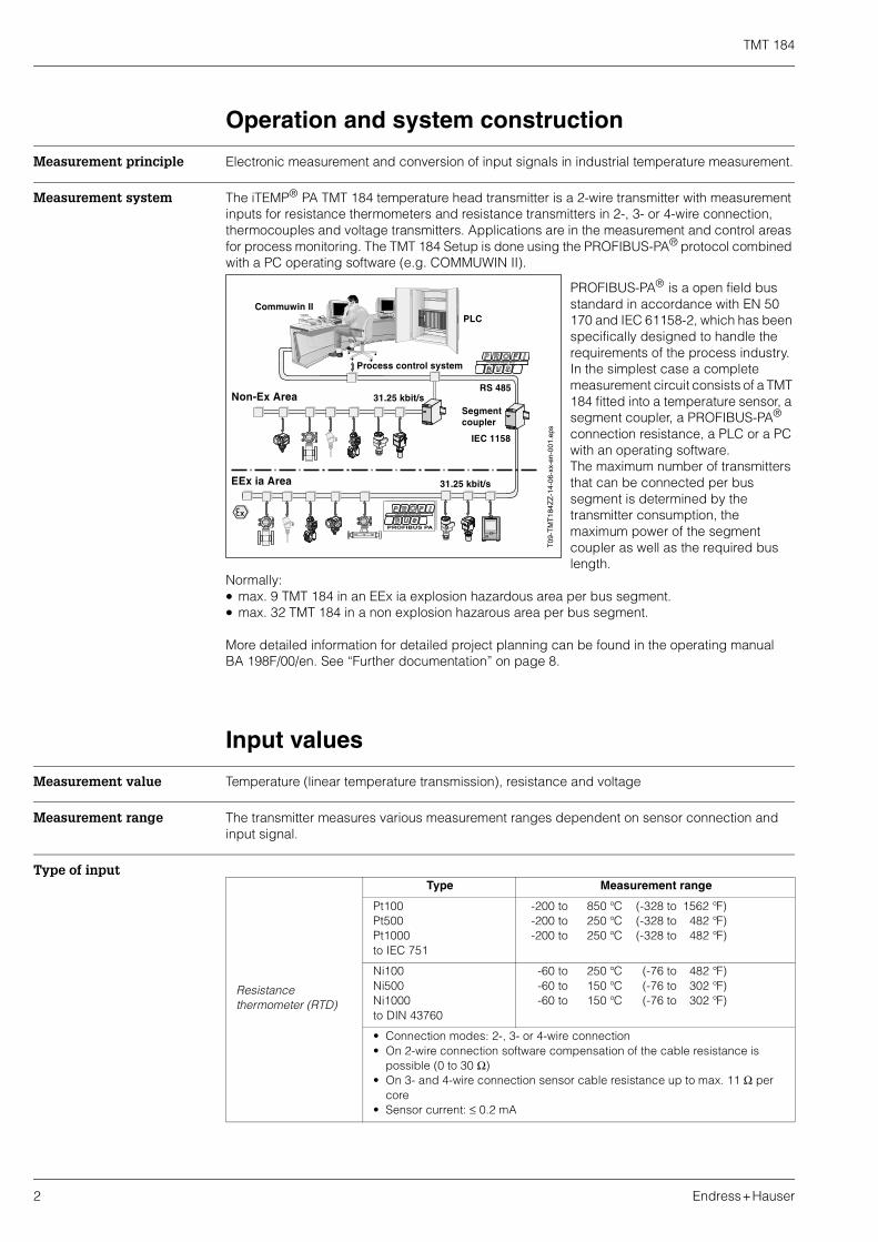
Measurement system The iTEMP® PA TMT 184 temperature head transmitter is a 2-wire transmitter with measurement inputs for resistance thermometers and resistance transmitters in 2-, 3- or 4-wire connection, thermocouples and voltage transmitters. Applications are in the measurement and control areas for process monitoring. The TMT 184 Setup is done using the PROFIBUS-PA® protocol combined with a PC operating software (e.g. COMMUWIN II).
PROFIBUS-PA® is a open field bus standard in accordance with EN 50 170 and IEC 61158-2, which has been specifically designed to handle the requirements of the process industry. In the simplest case a complete measurement circuit consists of a TMT 184 fitted into a temperature sensor, a segment coupler, a PROFIBUS-PA® connection resistance, a PLC or a PC with an operating software.The maximum number of transmitters that can be connected per bus segment is determined by the transmitter consumption, the maximum power of the segment coupler as well as the required bus length.
Normally:• max. 9 TMT 184 in an EEx ia explosion hazardous area per bus segment.• max. 32 TMT 184 in a non explosion hazarous area per bus segment.
More detailed information for detailed project planning can be found in the operating manual BA 198F/00/en. See “Further documentation” on page 8.
Input values
Measurement value Temperature (linear temperature transmission), resistance and voltage
Measurement range The transmitter measures various measurement ranges dependent on sensor connection and input signal.
Type of input
T09
-TM
T18
4ZZ
-14-
06-x
x-en
-00
1.ep
s
Resistance thermometer (RTD)
Type Measurement range
Pt100Pt500Pt1000to IEC 751
-200 to 850 °C (-328 to 1562 °F)-200 to 250 °C (-328 to 482 °F)-200 to 250 °C (-328 to 482 °F)
Ni100Ni500Ni1000to DIN 43760
-60 to 250 °C (-76 to 482 °F)-60 to 150 °C (-76 to 302 °F)-60 to 150 °C (-76 to 302 °F)
• Connection modes: 2-, 3- or 4-wire connection• On 2-wire connection software compensation of the cable resistance is
possible (0 to 30 Ω)• On 3- and 4-wire connection sensor cable resistance up to max. 11 Ω per
core• Sensor current: ≤ 0.2 mA
TMT 184
Endress+Hauser 3
Output values
Output signal Physical data transmission (Physical Layer Type):Fieldbus interface in accordance to IEC 61158-2
Failure signal Status message according to the PROFIBUS-PA® Profile V3.0 specification
Galvanic isolation 2 kV AC
Filter Digital filter 1st degree: 0 to 100 s
Current consumption 10 mA ± 1 mA
Error current 0 mA
Switch on delay ~ 10 s
Data transmission speed 31.25 kBit/s, voltage mode
Signal code Manchester II
Resistance transmitter Resistance (Ω)10 to 400 Ω10 to 2000 Ω
Thermocouple (TC)
B (PtRh30-PtRh6)C (W5Re-W26Re)I
D (W3Re-W25Re)I
E (NiCr-CuNi)J (Fe-CuNi)K (NiCr-Ni)L (Fe-CuNi)II
N (NiCrSi-NiSi)R (PtRh13-Pt)S (PtRh10-Pt)T (Cu-CuNi)U (Cu-CuNi)II
to IEC 584 Part 1
0 to +1820 °C (32 to 3308 °F)0 to +2320 °C (32 to 4208 °F)0 to +2495 °C (32 to 4523 °F)
-270 to +1000 °C (-454 to 1832 °F)-210 to +1200 °C (-346 to 2192 °F)-270 to +1372 °C (-454 to 2501 °F)-200 to +900 °C (-328 to 1652 °F)-270 to +1300 °C (-454 to 2372 °F)
-50 to +1768 °C (-58 to 3214 °F)-50 to +1768 °C (-58 to 3214 °F)
-270 to +400 °C (-454 to 752 °F)-200 to +600 °C (-328 to 1112 °F)
• Installation area:Connection head according to DIN 43 729 Form B; Field housing TAF 10
Application conditions (ambient conditions)
Ambient temperature −40 to +85 °C (for hazardous areas see Ex certification)
Storage temperature -40 to +100 °C
Climatic class according to EN 60 654-1, Class C
Condensation allowable
Ingress protection IP 00, IP 66 installed
Impact and vibration protection
4g / 2 to 150 Hz to IEC 60 068-2-6
Electromagnetic compatibility (EMC)
Interference immunity and emission according to EN 61 326-1 (IEC 1326) and NAMUR NE 21
Mechanical construction
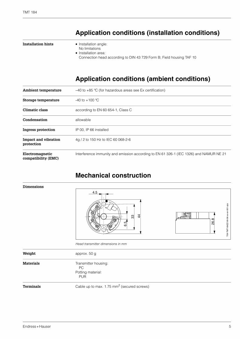
Dimensions
Head transmitter dimensions in mm
Weight approx. 50 g
Materials Transmitter housing:PC
Potting material:PUR
Terminals Cable up to max. 1.75 mm2 (secured screws)
T09
-TM
T1
84Z
Z-0
6-06
-xx-
en-0
01.e
ps
TMT 184
6 Endress+Hauser
Display and operating system
Remote operation Operation via PROFIBUS-PA® using a suitable configuration or operating software.
Certification
Ex-certification Details regarding the availability of the Ex versions (ATEX, FM, CSA, etc.) can be obtained from your local E+H sales organisation. All relevant data for hazardous area protection can be found inseparate Ex documentation, which can be requested separately.
CE mark The measurement system complies with the legal requirements laid out within the EU regulations. Endress+Hauser acknowledges successful testing of the unit by adding the CE mark.
How to order
Questionnaire
Standard setup / Standardeinstellung
Sensor TC ( ) B ( ) C ( ) D ( ) E ( ) J
( ) K ( ) L ( ) N ( ) R ( ) S
( ) T ( ) U
RTD ( ) Pt100 ( ) Pt500 ( ) Pt1000
( ) Ni100 ( ) Ni500 ( ) Ni1000
( ) 2 wire ( ) 3 wire ( ) 4 wire
Unit / Einheit ( ) °C ( ) °F
Range / Messbereich Low scale
(not / nicht PROFIBUS-PA) Anfang
Bitte beachten!:Messbereich und min. Spanne(s. Techn. Daten)
High scale
Ende
Note!:Range and min. span(s. Techn. data)
Bus address / Busadresse [0...126](only / nur PROFIBUS-PA)
Questionnaire Endress+Hauser iTEMP temperature transmitter
Customer specific setup / Kundenspezifische Einstellung
,
,
,
(only / nur PCP)
[0, 1, 2,..., 100s]
TMT 184
Endress+Hauser 7
Order structure
Accessories
Installation accessories are contained in the delivery contents.
Head transmitter iTEMP® PA TMT 184
Universally settable for resistance thermometer, thermocouple, resistance and voltage transmitter; power supply and communication using two wire technology according to IEC 61158-2. PROFIBUS-PA® Profile V3.0; current consumption
max. 11 mA; Output block for PROFIBUS-PA® display; for installation in Form B connection head according to DIN 43729.
CertificationA Version for non hazardous areas
B ATEX II 1G EEx ia IIC T4/T5/T6
C FM IS, Class I, Div. 1+2, Group A, B, C, D
D CSA IS, Class I, Div. 1+2, Group A, B, C, D
E ATEX II 3G EEx nA IIC T4/T5/T6
F ATEX II 3D
G ATEX II 1G EEx ia IIC T6, II3D
H ATEX II 3G EEx nA IIC T6, II3D
Configuration transmitter connectionA Standard factory configuration 3-wire
3 RTD (3-wire)
4 RTD (4-wire)
2 RTD (2-wire)
1 Thermocouple (TC)
Configuration temperature sensorA Standard factory configuration Pt100
1 Pt100
2 Ni100
3 Pt500
4 Ni500
5 Pt1000
6 Ni1000
7 Resistance transmitter 10 to 400 Ohm
8 Resistance transmitter 10 to 2000 Ohm
B Type B
C Type C
D Type D
E Type E
J Type J
K Type K
L Type L
N Type N
R Type R
S Type S
T Type T
U Type U
V Voltage transmitter -10 to 75 mV
ConfigurationA Standard factory setup [Pt100/3-wire/addr. 126]
B Customer specific sensor type and bus address
C Customer specific expanded settings TC (see questionnaire)
D Customer specific expanded settings RTD (see questionnaire)
ModelA DIP switch (bus address)
C DIP switch (bus address) + Works calibration certificate, 6 test points
System Information iTEMP® temperature transmitters (SI 008R/09/en)System Information PROFIBUS-PA® (SI 005S/04/en, SI 027F/09/en)Operating manual iTEMP® PA TMT 184 (BA 115R/09/a3)Ex additional documentation: ATEX II 1G: XA 008R/09/a3,ATEX II 3G: XA 012R/09/a3,ATEX II 3D: XA 028R/09/a3, FM, CSA, etc.Operating manual ’Field Communication PROFIBUS-DP / -PA’ (BA 198F/00/en)
On the Internet: www.endress.com ⇒ PRODUCTS ⇒ Product Portfolio ⇒ Process Solutions ⇒ PROFIBUS