24
Testing buildings for air leakage CIBSE Technical Memoranda TM23: 2000 The Chartered Institution of Building Services Engineers 222 Balham High Road, London SW12 9BS
Testing buildings for air leakage
CIBSE Technical Memoranda TM23: 2000
The Chartered Institution of Building Services Engineers 222 Balham High Road, London SW12 9BS
The rights of publication or translation are reserved.
No part of this public;ition m;:iy hP rPprorl11cPrl, ~tnr1>rl in a retrieval system or transmitted in any form or by any means without the prior permission of the Institution.
©October 2000 The Chartered Institution of Building Services Engineers London
Registered charity number 278104
ISBN 1 903287 10 3
This document is based on the best knowledge available at the time of publication. However no responsibility of any kind for any injury, death, loss, damage or delay however caused resulting from the use of these recommendations can be accepted by the Chartered lmlilulio11 of Buildiny Services Engineers, the authors or others involved in its publication . In adopting these recommendations for use each adopter uy doing so agrees to accept full responsibility for any personal injury, death, loss, damage or delay arising out of or in connection with their use by or on behalf of such adopter irrespective of the cause or reason therefore and agrees to defend, indemnify and hold harmless the Chartered Institution of Building Services Engineers, the authors and others involved in their publication from any and all liability ;:iri~ing out of or in connection with such use as aforesaid and irrespective of any negligence on the part of those indemnified .
Note from the publisher: This publication is primarily intended to provide guidance to those responsible for the design, installation, commissioning, operation and maintenance of building services. It is not intended to be exhaustive or definitive and it will be necessary for users of the guidance given to exercise their own rrofP"inn;il judQement when deciding whether to abide by or depart from it.
Typeset by CIBSE Editorial Department
Printed in Great Britain by Page Brothers Ltd, Norwich, Norfolk
Cover photograph: La Grande Arche de la Defense, Paris-designed by Johan von Spreckelsen in 1982, and for which air issues were critical to the success of the project.
Foreword
Pressure testing techniques have long been used in the laboratory on building components such as windows, for example, to ensure that rain will not penetrate them under windy conditions. Market leaders in low-energy buildings have been using pressure testing techniques for several years on the whole completed building to ensure a good build quality in terms of the provision of a well-sealed building in relation to air leakage. Although the emphasis was initially on domestic buildings, there has been increasing interest in non-domestic buildings, and in particular in industrial buildings and retail stores. In addition, research on buildings in the UK has resulted in an improved understanding of air leakage in relation to building design. It has provided a database on the range of air leakage rates that are currently generally achieved in practice - and on what improvements might be achieved with better-quality design.
Britain has now accepted the European test standard (prEN 13829) for pressure testing of buildings. This Technical Memorandum sets out to describe how users can comply with the standard, and provides some guidance on levels of airtightness to aim for and how these might be achieved.
Acknowledgements
The technical note has been produced by the CIBSE Task Group on Mechanical Ventilation. The Task Group members include:
I Andrews (Vent Axia Ltd) D Braham (Termodeck) G Brundrett (CIBSE) N Jones (Woods) P Jones (Chair) (Welsh School of Architecture) P Langford (Colt International Ltd) B Webb (BRE) M Duggan (FETA)
A focus group meeting was held to provide advice in preparing the document, and the following people contributed:
N Potter (BSRIA) R Stephen (BRE) S Borland (Building Sciences Ltd) D Lawson (Building Sciences Ltd) P Jackman (BSRIA)
R Harris of the Centre for Window and Cladding Technology, Bath, contributed to Appendix AZ on gasket sealing.

Contents
1 Introduction
2 Aim
3 Background
3.1 What is air leakage?
3.2 Why measure air leakage?
3.3 Air leakage parameters: air leakage index and air permeability
3.4 Design and construction for air tightness
4 Method
4.1 Air leakage test
4.2 Carrying out a pressure test
4.3 Interpretation of data: air leakage index and air permeability
4.4 Location of air leakage
4.5 Effective leakage area
5 Recommended air leakage standards
6 Air leakage tests and infiltration rate
References
Bibliography
Appendices
Appendix A 1: Fan pressurisation testing: data analysis to correct to standard conditions
Appendix A2: Design and construction guidance
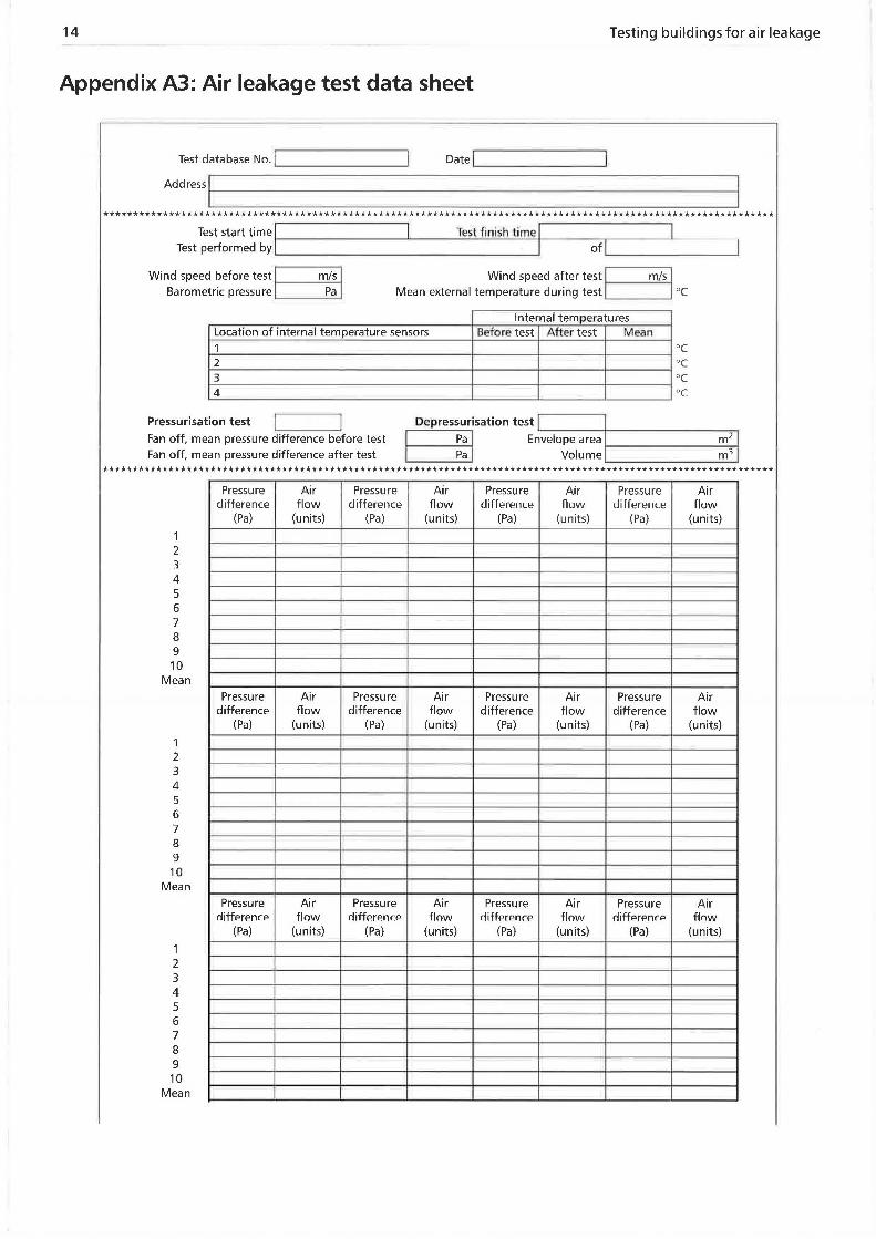
Appendix A3: Air leakage test data sheet
Index
1
1
1
2
3
5
5
5
7
8
8
9
9
10
10
10
11
11
12
14
15

Testing buildings for air leakage
1 Introduction
Ventilation is needed in buildings to provide fresh air for occupants, to dilute pollutants, and to exhaust heat gains. In the past buildings were, by their nature, leaky, and much of the required ventilation was provided by this fortuitous air leakage, usually referred to as air infiltration. In the design and construction of modern buildings the aim is to provide an airtight envelope and to introduce ventilation in a controllable way either naturally or mechanically, or by a combination of both. However, the reality is that few buildings are sufficiently airtight to allow this to happen. This is mainly due to the failure of the designers and builders fully to understand and appreciate the need for an airtight construction, and to be able to achieve this throughout the design, construction and lifetime of the building. This results in buildings that allow air leakage though the building envelope and, because this is uncontrollable-in both quantity and location-there are often excessive rates of ventilation. These can, in turn, incur:
a significant energy penalty
inability of the heating system to meet comfort levels
cold draughts
failure of the designed ventilation system, whether it be natural or mechanical
polluted air entering the building
reduced U-value of the construction.
There is an increasing demand from clients to reduce air leakage in non-domestic buildings, and many clients are specifying a pressurisation test at the time of completion of construction. The BRE Building Environmental Assessment Method (BREEAM) gives credit for a building design if it is to have an air leakage test on completion of construction. The majority of new dwellings are built on speculative developments, the absence of a purchaser's specification leading to little attention being given to airtightness in that sector of the industry.
However, when increasing the airtightness of the building envelope, designers must ensure that adequate ventilation is provided by the ventilation system. The requirements for non-domestic buildings and dwellings differ for reasons of occupation and use. Adequate means of ventilation for combustion appliances and for the removal of moisture from dwellings should always be considered.
2 Aim
This publication provides guidance for air leakage testing of non-domestic buildings and dwellings. It describes how to carry out a test with reference to an internal air pressure difference of 50 Pa, and the analysis required to determine the two building air leakage parameters currently being used, air permeability and air leakage index. It includes a description of these air leakage parameters and their use with regards to regulatory and air infiltration modelling, and describes how to interpret them to define an accepted measure of air leakage. It provides recommended air leakage indices and air permeability values for comparison. Guidance is also given on how to design to minimise air leakage in non-domestic buildings. At the time of writing, guidance on minimising air leakage in dwellings is still being developed. However, many of the methods and details developed for non-domestic buildings can also be applied in dwellings.
The guide provides recommended airtightness standards for offices, supermarkets, industrial buildings and dwellings. These are building types for which data exists. However, other comparable building types can be considered to have similar achievable air leakage rates depending on their construction type.
3 Background
3.1 What is air leakage?
Air leakage is the fortuitous infiltration and exfiltration of air through a building envelope or component due to imperfections in its construction. It takes place, for example, through:
cracks around doors, windows, panels, and cladding details
gaps where the structure penetrates the construction envelope
service entries: pipes, ducts, flues, ventilators
porous constructions: bricks, blocks, mortar joints
joist connections within intermediate floors.
It can also detract from the thermal performance of a construction, by providing a ventilation path within the construction for heat loss, therefore 'short-circuiting' the thermal insulation, and reducing the U-value of the construction.
2
3.2 Why measure air leakage?
There are four main reasons for measuring air le;ik;ige of buildings:
· ni CL
L/1 N
50
10 40 Qi
"7)
B ~
1. 30 ..c --1 Qi Cl">
"' ~ 20 Qi
I
10
0
To identify ways of reducing heat loss: The air leakage component of ventilation, usually referred to as infiltration, can be significant. Indeed, some buildings are ventilated just by infiltration, with no designed ventil~tion ::it ~11. Rf"rRuse infiltration is uncontrollable, the overall ventilation rate can be excessive in comparison with Lhe fn::sh air needs of the occupants. This may occur during times of high wind speed or large differences between the internal and external air temperature, resulting in a major increase in the heating or cooling load of the building.
To size heating, ventilation and air-conditioning (HVAC) systems accurately : The uncontrollable naLure uf air lt:akage can have an impacr on rhe sizing of HVAC systems. In some cases, the air
Dwellings
... (a)
Offices Industrial
, .. r-r----...:.
.. -(b)
Testing buildings for air leakage
leakage of a building may be so great that the HVAC
system cannot provide comfort conditions during extremes of seasonal weather conditions, sud1 as when it is cold or windy. Systems are often 'oversized' to offset uncertainties in air leakage.
To avoid draught discomfort: Air leakage can give rise to localised draught discomfort for people located near the area of leakage: for example, near poorly sealed windows or leaky roofs.
To control ventilation: Excessive air leakage makes it difficult to control ventilation systems. For example, in naturally ventilated buildings with trickle ventilators, excessive air leakage detracts from their performance. Problems also arise in relation to the control of the location of air intake to a building, say on polluted sites, where air leakage can provide an unplanned path for polluted air entering the building.
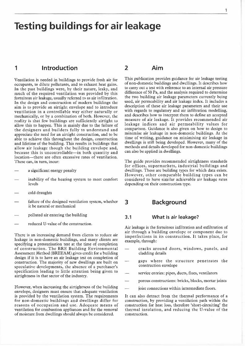
• Swedish Building Regulations
0 North America
United Kingdom
• lJnitPd Kingdom post 1990 Builrling Regulations
• United Kingdom post 1979 Building Regulations
rrior to United Kingdom Building Regulations
Figure 1 Comparison of air leakage standards for dwellings, offices and industrial buildings (Building Services J ournal, September 1997)
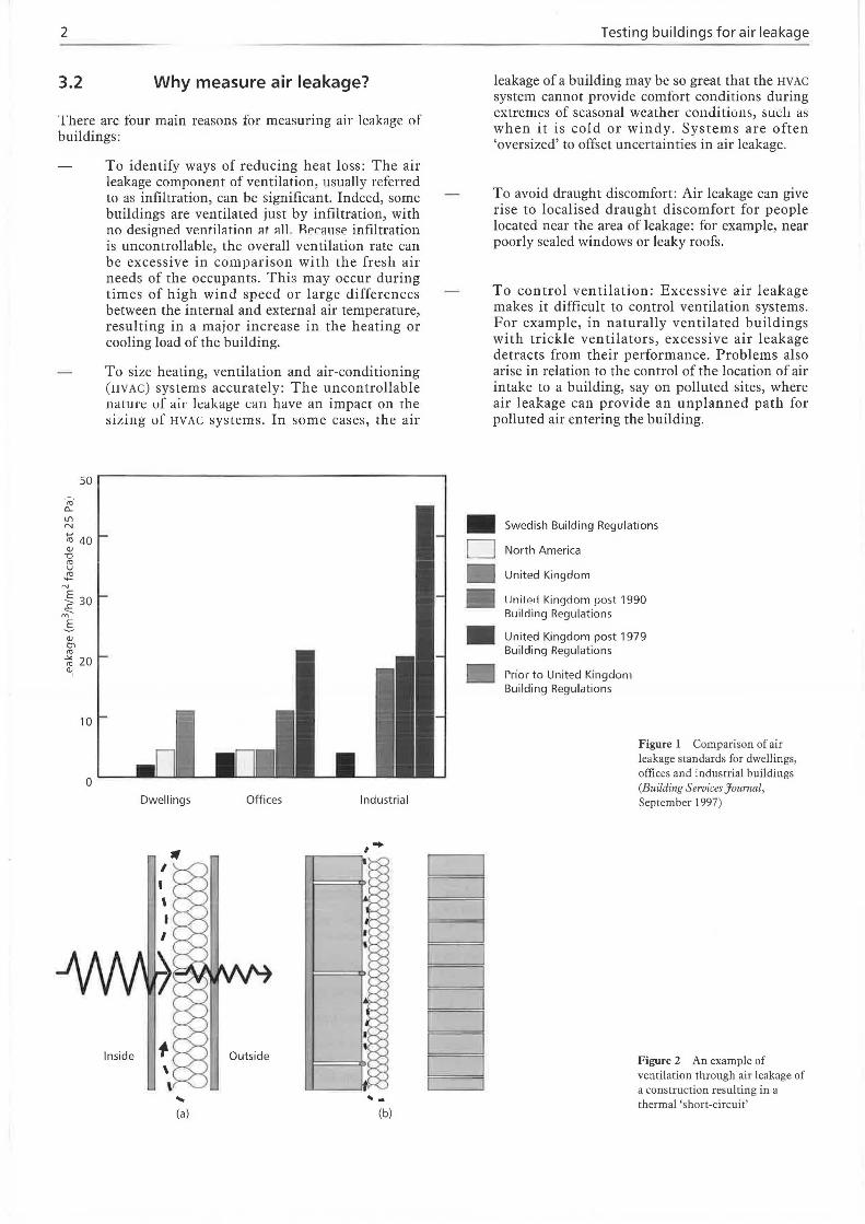
Figure 2 An example of ventilation through air leakage of a construction resulting in a thermal 'short-circuit'
Background
II
.... "
,.. ' ~
1 pout
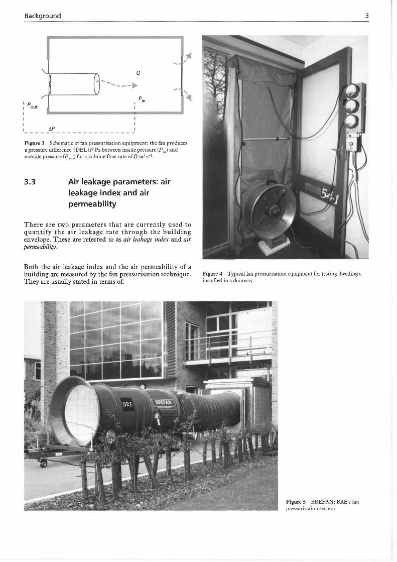
Figure 3 Schematic of fan pressurisation equipment: the fan produces a pressure difference {DEL}P Pa between inside pressure (P in) and outside pressure (Pout) for a volume flow rate of Q m3 s-1•
3.3 Air leakage parameters: air leakage index and air permeability
There are two parameters that are currently used to quantify the air leakage rate through the building envelope. These are referred to as air leakage index and air permeability.
Both the air leakage index and the air permeability of a building are measured by the fan pressurisation technique. They are usually stated in terms of:
Figure 4 Typical fan pressurisation equipment for testing dwellings, installed in a doorway
Figure 5 BREF AN: BRE's fan pressurisation system
3
4
Q 50
50 Pa
Figure 6 Air leakage characteristic curve: airflow rate plotted against pressure difference
the volume flow per hour (m3 h-1) of air supplied to the space by the air-moving equipment, per square metre (m2) of building envelope area for a specified internal to exLemal pressure difference of 50 Pa: for example, 10 m3 h-1 m-2 at 50 Pa.
The building envelope area is the boundary or barrier separating the interior volume of the building from the outside environment. It normally includes any surface that is a boundary between the conditioned internal space and the external environments.
The difference between the two air leakage parameters consists in the choice of building envelope area. The air leakage index does not include the solid ground floor area, while the air permeability does include the solid ground flour area. IL is not possible to standardise on one air leakage parameter at present because: (a) the proposed European Standard prEN 13829 and Part L of the Building Regulations use air permeability; (b) the historical database of air leakage rate values relates to air leakage index. The choice of which air leakage parameter to use is therefore dependent upon the context of its USC.
3.3.1 Air leakage index
For the parameter air leakage index the buiJdjng envelope area, S (m2), is defined as the internal surface area of the external fa<;:ade, and is calculated from the dimensions
Figure 7 A smoke pencil indicating air leakage through a leaky window frame
Testing buildings for air leakage
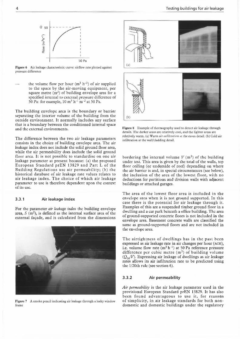
(a)
(b)
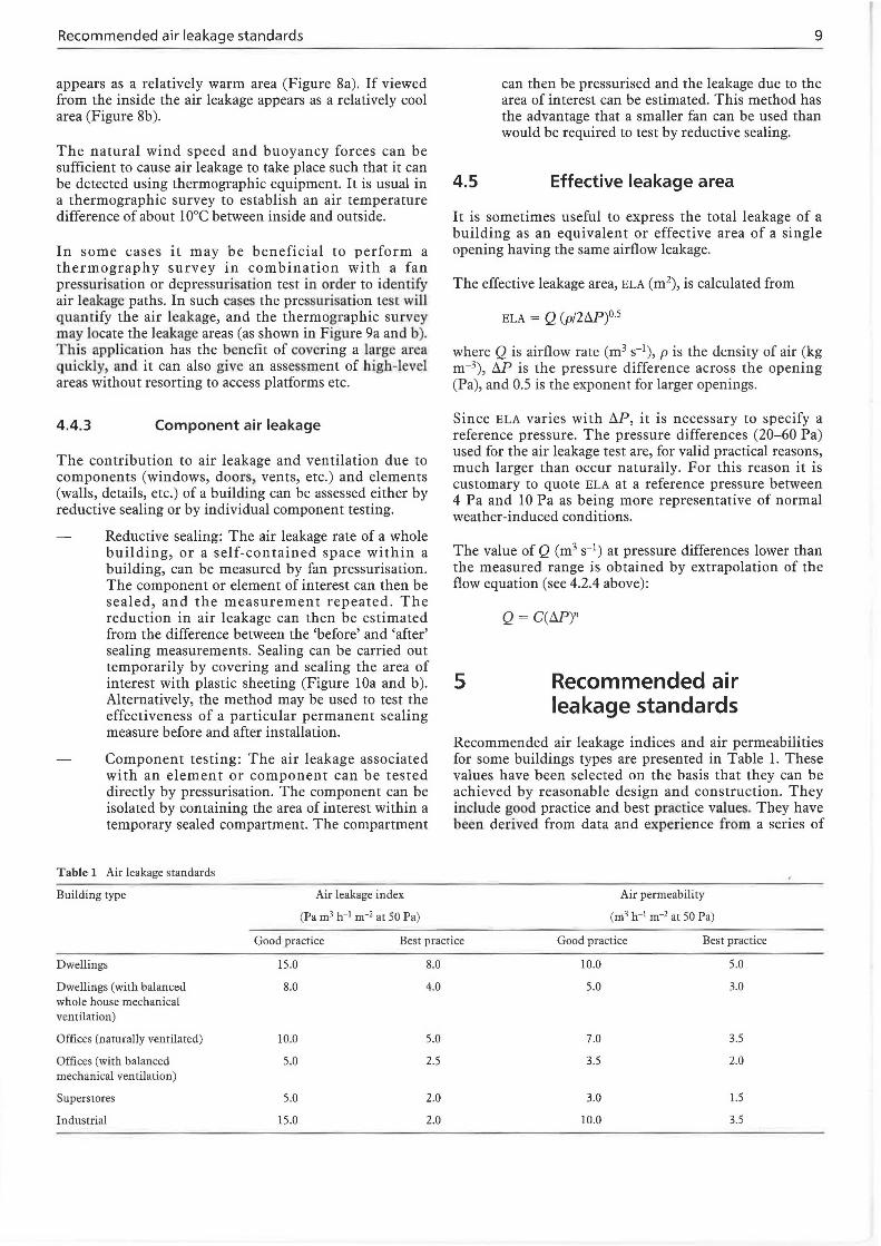
Figure 8 Example ofthermography used to detect air leakage through details. The darker areas are relatively cool, and the lighter areas are relatively warm. (a) Warm air exfiltrnrinn at the eaves detail. (b) Cold air infiltration at the wall/cladding detail.
bordering the internal volume V (m3) of the building under test. This area is given by the total of the walls, top floor ceiling (or underside of roof) depending on where the air barrier is and, in special circumstances (see below), the inclusion of the area of the lowest floor, with no deductions for partitions and division walls with adjacent buildings or attached garages.
The area of the lowest floor area is included in the envelope area when it is not ground supported. In this case there is the potential for air leakage through it. Examples of this are a suspended timber ground floor in a dwelling and a car park beneath a office building. The area of ground-supported concrete floors is not included in the envelope area. Basement concrete walls are classified the same as ground-supported floors and are not included in the envelope area.
The airtightness of dwellings has in the past been expre-Ssed as air leakage rate in air changes per hour (ACH), i.e. volume flow rate (m 3 h-1) at 50 Pa reference pre sure difference per cubic metre (m 3) of building volume (Q5of V). Expressing air leakage of dwellings as air leakage rates allows its air infiltration rate to be predicted using the l/20th rule (see section 6).
3.3.2 Air permeability
Air permeability is the air leakage parameter used in the provisional European Standard prEN 13829. It has also been found advantageous to use it, for reasons of simplicity, in air leakage standards for both nondomestic and domestic buildings under the regulatory
Method 5
(a) (b)
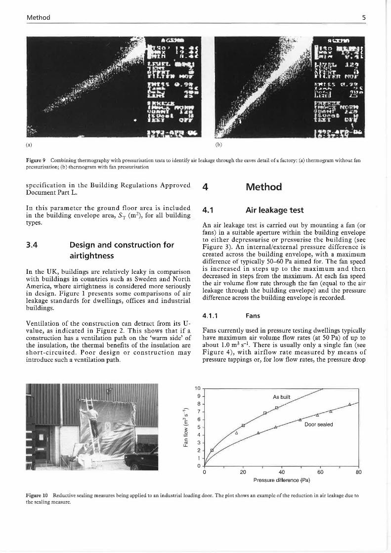
Figure 9 Combining thermography with pressurisation tests to identify air leakage through the eaves derail of a factory: (a) rhermogram without fan pressurisation; (b) rhermogram with fan pressurisation
specification in the Building Regulations Approved Document Part L.
In this parameter the ground floor area is included in the building envelope area, ST (m2), for all building types.
3.4 Design and construction for airtightness
In the UK, buildings are relatively leaky in comparison with buildings in countries such as Sweden and North America, where airtightness is considered more seriously in design. Figure 1 presents some comparisons of air leakage standards for dwellings, offices and industrial buildings.
Ventilation of the construction can detract from its Uvalue, as indicated in Figure 2. This shows that if a construction has a ventilation path on the 'warm side' of the insulation, the thermal benefits of the insulation are short-circuited. Poor design or construction may introduce such a ventilation path.
I (/)
"' .s 3: 0
:;:= c: ca u..
10
9
8
7
6
5
4
3 2
4 Method
4.1 Air leakage test
An air leakage test is carried out by mounting a fan (or fans) in a suitable aperture within the building envelope to either depressurise or pressurise the building (see Figure 3). An internal/external pressure difference is created across the building envelope, with a maximum difference of typically 50-60 Pa aimed for. The fan speed is increased in steps up to the maximum and then decreased in steps from the maximum. At each fan speed the air volume flow rate through the fan (equal to the air leakage through the building envelope) and the pressure difference across the building envelope is recorded.
4.1.1 Fans
Fans currently used in pressure testing dwellings typically have maximum air volume flow rates (at 50 Pa) of up to about 1.0 m3 s-1• There is usually only a single fan (see Figure 4), with airflow rate measured by means of pressure tappings or, for low flow rates, the pressure drop
20 40 60 80 Pressure difference (Pa)
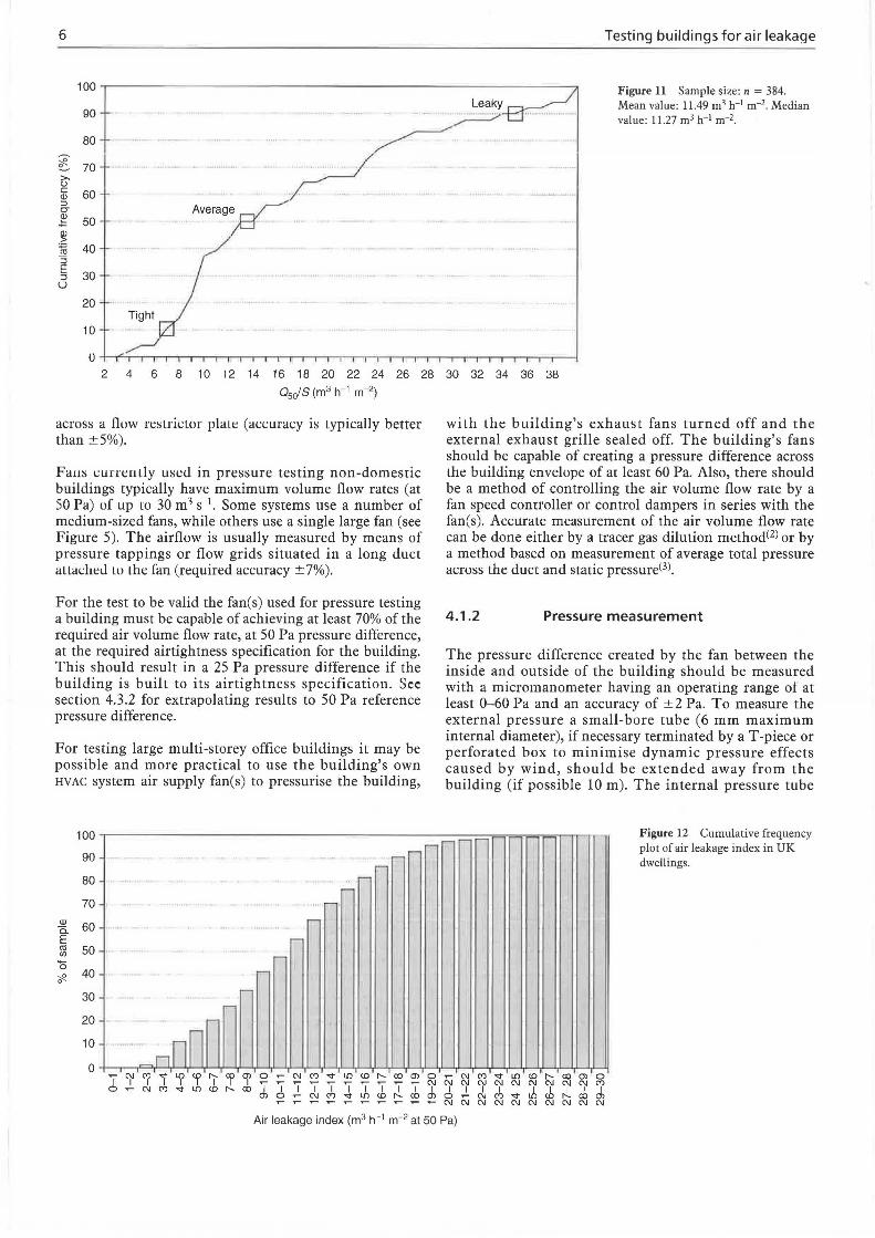
Figure 10 Reductive sealing measures being applied to an industrial loading door. The plot shows an example of the reduction in air leakage due to the sealing measure.
6
100
90
80
~ 70 >. u c 60 Q) :J CJ
~ 50
~ ~ 40 "5 E
30 :J u
20
10
Ave rag~
..... .............. w
Tight
Testing buildings for air leakage
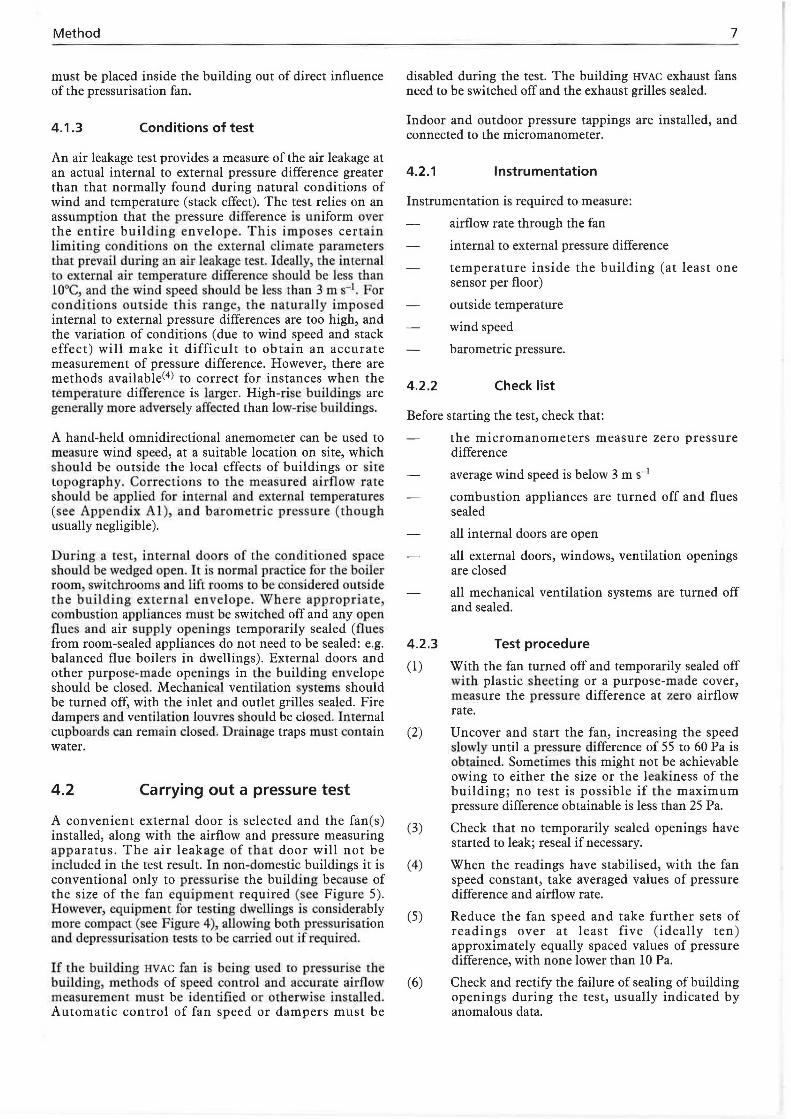
Figure 11 Sample size: n = 384. Mean value: 11.49 m 3 h-1 m-2. Median value : 11.27 m 3 h-1 m-2.
4 6 8 1 0 12 14 16 18 20 22 24 26 28 30 32 34 36 38 0 5ofS (m3 h-1 m-2)
across a flow restrictur plate (accuracy is typically better than ±5%).
Faus currently used in pressure testing non-domesdc buildings typically have maximum volume flow rates (at SO Pa) of up to 30 m3 s 1. Some sysrems use a number of medium-sized fans, while others use a single large fan (see Figure 5). The airflow is usually measured by means of pressure tappings or flow grids situated in a long duct attached Lu the fan (required accuracy ±7%).
For the test to be valid the fan(s) used for pressure testing a building must be capable of achieving at least 70% of the required air volume flow rate, at 50 Pa pressure difference, at the required airtightness specification for the building. This should result in a 25 Pa pressure difference if the building is built to its airtightness specification. See section 4.3.2 for extrapolating results to 50 Pa reference pressure difference.
For testing large multi-storey office buildings it may be possible and more practical to use the building's own HVAC system air supply fan(s) to pressurise the building,
100
90 - -r-
80 -70 - .
w -c. 60 E -C1l 50 .. (/) -a
40 -~ 0
30 ..-
20
10 nnn 0
I ~ M "<!' L!) "' I'- CXl Ol 0 N M "<!' L!) "' I'- CXl Ol I I I I I I I d: :!: I I I I I I I I 0 N M '<!' L!) "' I'- CXl
~ N M "<!' L!) "' I'- CXl ~
r-
0
with the building's exhaust fans turned off and the external exhaust grille sealed off. The building's fans should be capable of creating a pressure difference across the building envelope of ar leasr 60 Pa. Also, there should be a method of controlling the air volume flow rate by a fan speed comroller or control dampers in series with the fan(s). Accurate measurement of the air volume flow rate can be done either by a tracer gas dilution methodC2l or by a method based on measurement of average total pressure across the duct and static pressureC3l.
4.1.2 Pressure measurement
The pressure difference created by the fan between the inside and outside of the building should be measured with a micromanometer having an operating range ot at least 0-60 Pa and an accuracy of ±2 Pa. To measure the external pressure a small-bore tube (6 mm maximum internal diameter), if necessary terminated by a T-piece or perforated box to minimise dynamic pressure effects caused by wind, should be extended away from the building (if possible 10 m). The internal pressure tube
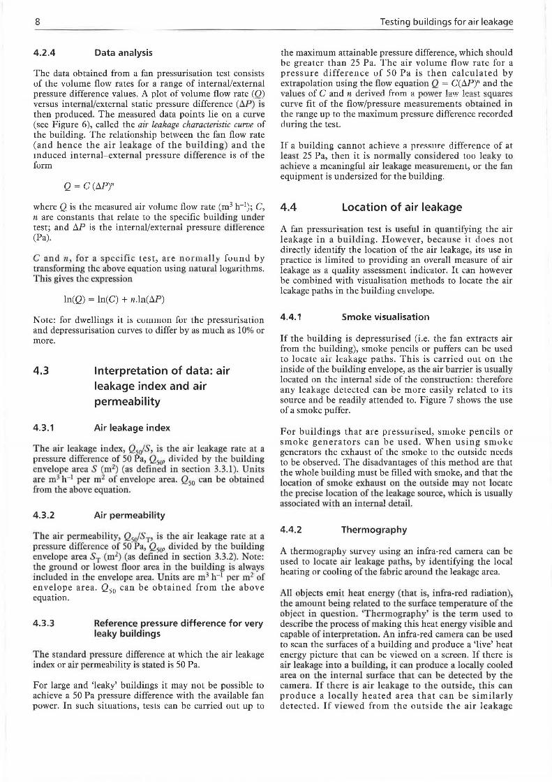
- Figure 12 Cumulative frequency r- r-
plot of air leakage index in UK dwellings.
N M "<!' L!) "' I'- CXl Ol 0
~ ~ N N N N N N ~ N M I I I I I I I d ~ N M "<!' L!) "' I'- CXl
~ N N N N N N N N N N
Air leakage index (m3 h-1 m-2 at 50 Pa)
Method
must be placed inside the building out of direct influence of the pressurisation fan.
4.1.3 Conditions of test
An air leakage test provides a measure of the air leakage at an actual internal to external pressure difference greater than that normally found during natural conditions of wind and temperature (stack effect). The test relies on an assumption that the pressure difference is uniform over the entire building envelope. This imposes certain limiting conditions on rhe external climate parameters that prevail during an air leakage test. Ideally, the internal to external air temperature difference should be less than 10°C, and the wind speed should be less than 3 m s- 1• For conditions outside this range, the naturally imposed internal to external pressure differences are too high, and the variation of conditions (due to wind speed and stack effect) will make it difficult to obtain an accurate measurement of pressure difference. However, there are methods available<4l to correct for instances when the temperature difference is larger. High-rise buildings are generally more adversely affected than low-ri e buildings.
A hand-held omnidirectional anemometer can be used to measure wind speed, at a suitable location on site, which should be outside the local effects of buildings or site topography. Corrections ro the measured airflow rare should be applied for internal and external temperatures (see Appendix Al), and barometric pressure (though usually negligible).
During a rest, internal doors of che conditioned space should be wedged open. It is normal practice for the boiler room, swirchrooms and lift rooms to be considered outside rhe building external envelope. Where appropriate, combustion appliances must be switched off and any open flues and air supply openings temporarily sealed (flues from room-sealed appliances do not need to be sealed: e.g. balanced flue boilers in dwellings). External doors and other purpose-made openings in the building envelope should be closed. Mechanical ventilation systems should be turned off, with the inlet and outlet grilles sealed. Fire dampers and ventilation louvres should be closed. Internal cupboards can remain closed. Drainage traps mu t conrain water.
4.2 Carrying out a pressure test
A convenient external door is selected and the fan(s) installed, along with the airflow and pressure measuring apparatus. The air leakage of that door will not be included in the test result. In non-domestic buildings it is conventional only to pressurise the building because of the size of the fan equipment required (see Figure 5). However, equipment for testing dwellings is considerably more compact (see Figure 4), allowing both pressurisation and depressurisation tests co be carried out if required.
If the building HVAC fan is being used to pressurise the building, methods of speed control and accurate airflow measuremenc must be identified or otherwise installed. Automatic control of fan speed or dampers must be
7
disabled during the test. The building HVAC exhaust fans need to be switched off and the exhaust grilles sealed.
Indoor and outdoor pressure tappings are installed, and connected to the micromanometer.
4.2.1 Instrumentation
Instrumentation is required to measure:
airflow rate through the fan
4.2.2
internal to external pressure difference
temperature inside the building (at least one sensor per floor)
outside temperature
wind speed
barometric pressure.
Check list
Before starting the test, check that:
the micromanometers measure zero pressure difference
average wind speed is below 3 m s-1
combustion appliances are turned off and flues sealed
all internal doors are open
all external doors, windows, ventilation openings are closed
all mechanical ventilation systems are turned off and sealed.
4.2.3 Test procedure
(1) With the fan turned off and temporarily sealed off with plastic sheeting or a purpose-made cover, measure the pressure difference at zero airflow rate.
(2) Uncover and start the fan, increasing the speed slowly until a pressure difference of 55 to 60 Pa is obtained. Sometimes this might not be achievable owing to either the size or the leakiness of the building; no test is possible if the maximum pressure difference obtainable is less than 25 Pa.
(3) Check that no temporarily sealed openings have started to leak; reseal if necessary.
(4) When the readings have stabilised, with the fan speed constant, take averaged values of pressure difference and airflow rate.
(5) Reduce the fan speed and take further sets of readings over at least five (ideally ten) approximately equally spaced values of pressure difference, with none lower than 10 Pa.
(6) Check and rectify the failure of sealing of building openings during the test, usually indicated by anomalous data.
8
4.2.4 Data analysis
The data obtained from a fan pressurisation test consists uf Lht: volume flow rates for a range of internal/external pressure difference values. A plot of volume flow rate (Q) versus internal/external static pressure difference (11P) is then produced. The measured data points lie on a curve (see Figure 6), called the air leakage characteristic curve of the building. The relationship between the fan flow rate (and hence the air leakage of the building) and the induced internal-external pressure difference is of the form
where Q is the measured air volume flow rate (m3 h-1); C, n are constants that relate to the specific building under test; and D.P is the internal/external pressure difkrence (Pa).
C and n, for a s pecific test, are normall y fuuu<l by transforming the above equation using natUl'al logarithms. This gives the expre ion
ln(Q) = ln(C) + n.ln(D.P)
Note: for dwellings it is curnrnun for the pressurisation and depressurisation curves to differ by as much as 10% or more.
4.3
4.3.1
Interpretation of data: air leakage index and air permeability
Air leakage index
The air leakage index, Q JS, is the air leakage rate at a pressure difference of 50 ~a, Q50, ci iviclecl by the building envelope area S (m2) (as defined in ection 3.3.1). Units are m3 h- 1 per m2 of envelope area. Q50 can be obtained from the above equation.
4.3.2 Air permeability
The air permeability, Q5rJS,. i the air leakage rare at a pressure difference of SO Pa, Qso• divided by rhe building envelope area T (m2) (as defined in section 3.3.2). Nore: the ground or lowest floor area in the building is always induded in the envelope area. Units are m3 11- 1 per m2 of envelope area. Q50 can be obtained from the above equation.
4.3.3 Reference pressure difference for very leaky buildings
The standard pressure difference at which the air leakage index or air permeability is stated is 50 Pa.
For large and 'leaky' buildings it may not be possible to
achieve a SO Pa pressure difference with the available fan power. In such situations, tests can be carried out up to
Testing buildings for air leakage
the maximum attainable pressure difference, which should be greater than 25 Pa. The air volume flow rate for a pressure difference uf 50 Pa is then calculated by extrapolation using the flow equation Q = C(D.P)n and the values of C and n derive(t from a power law least squares curve fit of the flow/pressure measurements obtained in the range up to the maximum pressure difference recorded during the test.
If a building cannot achieve a pressnrc:- difference of at least 25 Pa, then it is normally considered too leaky to achieve a meaningful air leakage measmemenL, ur Lhe fan equipment is undersized for the building.
4.4 Location of air leakage
A fan pressurisation rest is useful in quantifying the air leakage in a building. However, because it does not directly identify the location of the air leakage, its use in practice is limited to providing an overall measure of air leakage as a quality assessment indicator. It can however be combined with visualisation methods to locate the air leakage paths in the building en vdope.
4.4.1 Smoke visualisation
If the building is depressurised (i.e. the fan extracts air from the building), smoke pencils or puffers can be used to locate air leakage palhs . This is carried out on the insid of the builuing envelope, as the air barrier is usually located on the internal side of the construction: therefore any leakage detected can be more easily related to its source and be readily attended to. Figure 7 shows the use of a smoke puffer.
For buildings that are pressurised, smoke pencils or smoke generators can be used. When using smoke generators the exhaust of the smoke to the outside needs to be observed. The disadvantages of this method are that the whole building must be filled with smoke, and that the location of smoke exhaust on the outside may not locate the precise location of the leakage source, which is usually associated with an internal detail.
4.4.2 Thermography
A thermography survt:y using an infra-red camera can be used to locate air leakage paths, by identifying the local heating or cooling of the fabric around the leakage area.
All objects emit hear energy (that is, infra-red radiation), the amount being related to the surface temperature of the object in question. 'Thermograpby' is the term used to
describe the process of making this heat energy visible and capable of interpretation. An infra-red camera can be used to scan the surfaces of a building and produce a 'live' heat energy picture that can be viewed on a screen. If there is air leakage into a building, it can produce a locally cooled area on the internal surface that can be detected by the camera. If there is air leakage to the outside, this can produce a locally heated area that can be similarly detected. If viewed from the outside the air leakage
Recommended air leakage standards
appears as a relatively warm area (Figure 8a). If viewed from the inside the air leakage appears as a relatively cool area (Figure 8b ).
The natural wind speed and buoyancy forces can be sufficient to cause air leakage to take place such that it can be detected using thermographic equipment. It is usual in a thermographic survey to establish an air temperature difference of about l0°C between inside and outside.
In some cases it may be beneficial to perform a thermography survey in combination with a fan pressurisation or depressurisacion test in order to identify air leakage paths. In such cases the pressurisation test will quantify the air leakage, and the thermographic survey may locate the leakage areas (as shown in Figure 9a and b). This application has the benefit of covering a large area quickly, and it can also give an assessment of high-level areas without resorting to access platforms etc.
4.4.3 Component air leakage
The contribution to air leakage and ventilation due to components (windows, doors, vents, etc.) and elements (walls, details, etc.) of a building can be assessed either by reductive sealing or by individual component testing.
Reductive sealing: The air leakage rate of a whole building, or a self-contained space within a building, can be measured by fan pressurisation. The component or element of interest can then be sealed, and the measurement repeated . The reduction in air leakage can then be estimated from the difference between the 'before' and 'after' sealing measurements. Sealing can be carried out temporarily by covering and sealing the area of interest with plastic sheeting (Figure lOa and b ). Alternatively, the method may be used to test the effectiveness of a particular permanent sealing measure before and after installation.
Component testing: The air leakage associated with an element or component can be tested directly by pressurisation. The component can be isolated by containing the area of interest within a temporary sealed compartment. The compartment
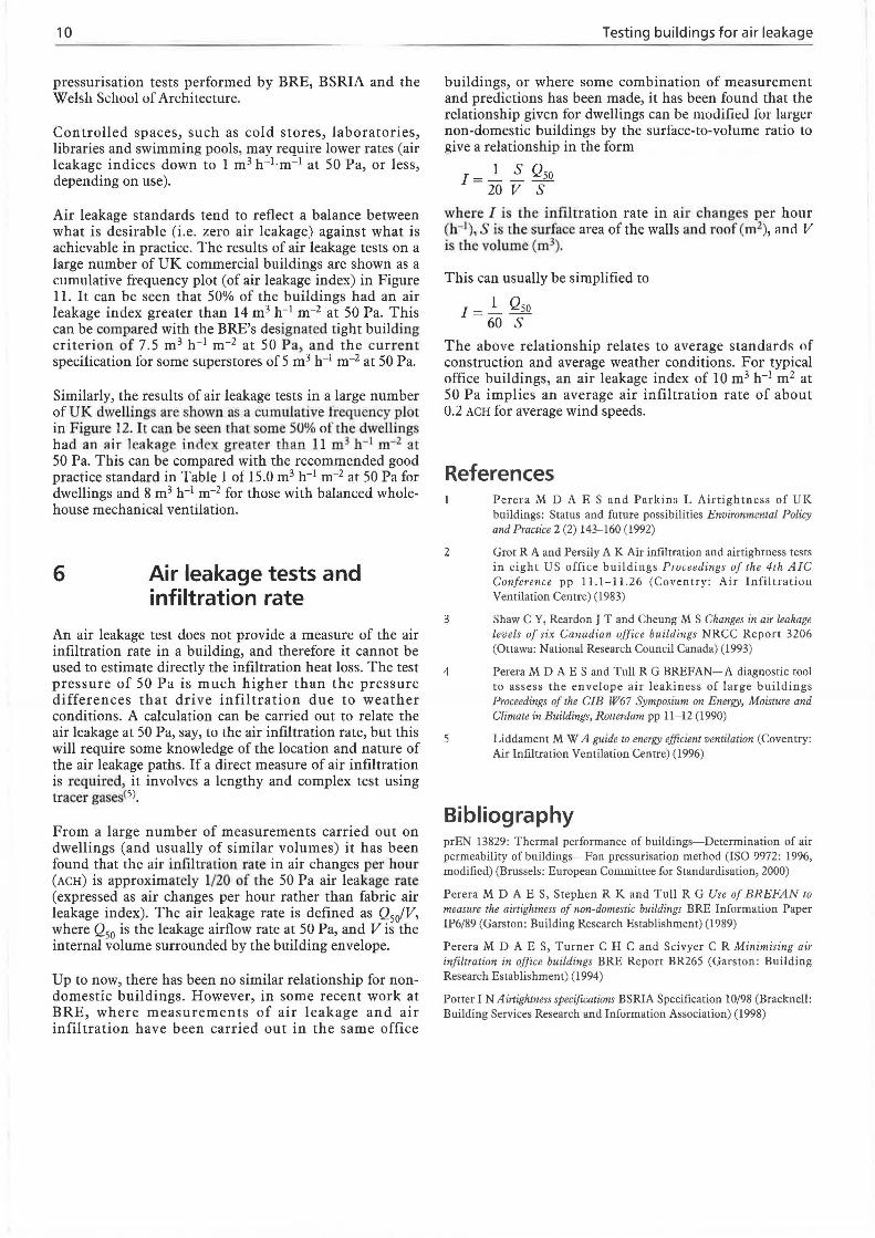
Table I Air leakage standards
Building type Air leakage index
(Pa m 3 h-1 m-2 at SO Pa)
4.5
9
can then be pressurised and the leakage due to the area of interest can be estimated. This method has the advantage that a smaller fan can be used than would be required to test by reductive sealing.
Effective leakage area
It is sometimes useful to express the total leakage of a building as an equivalent or effective area of a single opening having the same airflow leakage.
The effective leakage area, ELA (m2), is calculated from
ELA = Q (p/2!::.P)O.S
where Q is airflow rate (m3 s-1 ), p is the density of air (kg m-3), t::.P is the pressure difference across the opening (Pa), and 0.5 is the exponent for larger openings.
Since ELA varies with D.P, it is necessary to specify a reference pressure. The pressure differences (20-60 Pa) used for the air leakage test are, for valid practical reasons, much larger than occur naturally. For this reason it is customary to quote ELA at a reference pressure between 4 Pa and 10 Pa as being more representative of normal weather-induced conditions.
The value of Q (m3 s-1) at pressure differences lower than the measured range is obtained by extrapolation of the flow equation (see 4.2.4 above):
5
Q = C(!::.P)"
Recommended air leakage standards
Recommended air leakage indices and air permeabilities for some buildings types are presented in Table 1. These values have been selected on the basis that they can be achieved by reasonable design and construction. They include good practice and best practice values. They have been derived from data and experience from a series of
Air permeability
(m3 h-1 m-2 at SO Pa)
Good practice Best practice Good practice Best practice
Dwellings 15.0 8.0 10.0 s.o Dwellings (with balanced 8.0 4.0 s.o 3.0 whole house mechanical ventilation)
Offices (naturally ventilated) 10.0 5.0 7.0 3.S
Offices (with balanced s.o 2.S 3.5 2.0 mechanical ventilation)
Superstores s.o 2.0 3.0 1.5
Industrial lS .0 2.0 10.0 3.5
10
pressurisation tests performed by BRE, BSRIA and the Welsh School of Architecture.
Controlled spaces, such as cold stores, laboratories, libraries and swimming pools, mav reouire lower rates (air leakage indices down- to 1 m3 h-=-i.m:.1 at 50 Pa, or l~ss, depending on use).
Air leakage standards tend to reflect a balance between what is desirable (i.e. zero air leakage) against what is achievable in practice. The results of air leakage tests on a large number of UK commercial buildings arc shown as a rnmulative frequency plot (of air leakage index) in Figure 11. It can be seen that 50% of the buildings had an air leakage index greater than 14 m 3 h-1 m-2 at 50 Pa. This can be compared with the BRE's designated right building criterion of 7.5 m 3 h-1 m-2 at 50 Pa, and the current specification for some superstores of 5 m 3 h-1 m-2 at 50 Pa.
Similarly, the results of air leakage tests in a large number of UK dwellings are shown as a cumulative trequency plot in Figure 12. It can be een that some 50% of the dwellings had an air leakag index greater than 11 m3 h- 1 m- 2 at 50 Pa. This can be compared with the recommended good practice standard in Table l of 15.0 m3 h-1 m-2 at 50 Pa for dwellings and 8 m 3 h-1 m-2 for those with balanced wholehouse mechanical ventilation.
6 Air leakage tests and infiltration rate
An air leakage test does not provide a measure of the air infiltration rate in a building, and therefore it cannot be used to estimate directly the infiltration heat loss. The test pressure of 50 Pa is much higher than the pressure differences that drive infiltration due to weather conditions. A calculation can be carried out to relate the air leakage at 50 Pa, say, Lu Lhe air infiltration rate, but this will require some knowledge of the location and nature of the air leakage paths. If a direct measure of air infiltration is requil'ed, it involves a lengthy and complex test using tracer gases<5).
From a large number of measurements carried out on dwellings (and usually of similar volumes) it has been found that the air infiltration race in air changes per hour (ACH) is approximately 1/20 of the 50 Pa air leakage rate (expressed as air changes per hour rather than fabric air leakage index). The air leakage rate is defined as Q5JV, where Q50 is the leakage airflow rate at 50 Pa, and Vis the internal volume surrounded by the building envelope.
Up to now, there has been no similar relationship for nondomestic buildings. However, in some recent work at BRE, where measurements of air leakage and air infiltration have been carried out in the same office
Testing buildings for air leakage
buildings, or where some combination of measurement and predictions has been made, it has been found that the relationship given for dwellings can be modified fur larger non-domestic buildings by the surface-to-volume ratio to give a relationship in the form
I = _!_ !__ Qso 20 v s
where I is the infiltration rate in air changes per hour (h- 1), Sis rhe surface area of the walls and roof (rn2), :mcl V is the volume (m3).
This can usually be simplified to
1 = __!__ Qso 60 s
The above relationship relates to average standards of construction and average weather conditions. For typical office buildings, an air leakage index of 10 m 3 h-1 m 2 at 50 Pa implies an average air infiltration rate of about 0.2 ACH for average wind speeds.
References
2
3
4
5
Perera M D A E S and Parkins L Airtightness of UK buildings: Status and future possibilities Environmental Policy and Practice 2 (2) 143-160 (1992)
Grot R A and Persily A K Air infiltration and airtightness tests in eight US office buildings Prnceedings uf the 4th AIC Conference pp 11.1-11.26 (Coven try: Air Infiltration Ventilation Centre) (1983)
Shaw CY, Reardon J T and Cheung MS Changes in air leakage levels of six Canadian office buildings NRCC Report 3206 (Onawa: National Research Council Canada) (1993)
Perera MD AES and Tull R G BREFAN-A diagnostic tool to assess the envelope air leakiness of large buildings Proceedings of the GIB W67 Symposium on Energy, Moisture and Climate in Buildings, Rotterdam pp 11-12 (1990)
Liddament MW A guide to energy efficient ventilation (Coventry: Air Infiltration Ventilation Centre) (1996)
Bibliography prEN 13829: Thermal performance of buildings-Determination of air permeability of buildings-Fan pressurisation method (ISO 9972: 1996, modified) (Brussels: European Commiuee fur SLandardisation, 2000)
Perera M D A E S, Stephen R K and Tull R G Use of BREFAN to measure the airtightness of non-domestic buildings BRE Information Paper !P6/89 (Garston: Building Research Establishment) (1989)
Perera M D A E S, Turner C H C and Scivyer C R Minimising air infiltration in office buildings BRE Report BR265 (Garston: Building Research Establishment) (1994)
Potter IN Airtightness specifications BSRIA Specification 10/98 (Bracknell: Building Services Research and Information Association) (1998)

Appendices
Appendix A1: Fan pressurisation testing: data analysis to correct to standard conditions
When carrying out fan pressurisation tests, various corrections need to be applied to the data to take account of temperature/density variations in the test conditions. This also applies to calculated parameters, such as the air leakage index or air permeability, which need to be specified at a standard temperature and barometric pressure (i.e. 20°C and 101 325 Pa). Correcting the air leakage parameter to standard conditions enables tests carried out under different conditions to be properly compared.
There are three steps to the correction process:
(1)
(2)
(3)
Correct the readings from the airflow measuring device for differences between actual test conditions and those for which the device was calibrated.
Correct the measured airflow rates for differences in temperature between air passing through the airflow measuring device and air passing through the building envelope.
Correct the airflow rates through the building envelope to standard temperature and barometric pressure conditions (STP).
Step 1
Correction for the difference between actual conditions in the airflow measuring device and conditions when it was calibrated:
Q =Q ~ m c Pm
where Qm is the actual air volume flow rate in the measuring device, Q c is the air volume flow rate from calibration of the mea uring device> Pm is the air density in the measw·ing device (kg m-3), and Pc is the air density from calibration of the measuring device.
Note: the determination of the air density in the airflow measuring device will require measurements of both air temperature and barometric pressure.
Step 2
Correction for the indoor/outdoor temperature differences between air passing through the airflow measuring device and air passing through the building envelope.
Note: this correction should theoretically be carried out using differences in density. However, in the case below only air temperature is used, which gives a very similar result.
11
The correction to be applied depends on whether the building is being pressurised or depressurised.
(a) For pressurisation tests:
T1 + 273 Qenv(out) = Qm T + 273
0
where Q env(out) is the actual air volume flow rate out through the envelope, Ti is the mean indoor temperature during the test (°C), and T
0 is the mean temperature in the
measuremenc device during che rest (usually equals outdoor temperature) (°C).
(b) For depressurisation tests:
T0 + 273
Qenv(in) = Q,,, T. + 273 I
where Qcnv(in) is the actual air volume flow rate in through the envelope, T
0 is the mean outdoor temperature during
the test (°C), and T; is the mean temperature in the measurement device during rhe rest (usually equals indoor temperature) (°C).
Step 3
Correction of the airflow rates through the envelope to standard temperature and barometric pressure (STP), i.e. 20°C and 10 1325 Pa).
This correction is applied to the air leakage flow coefficient, C, as obtained from the data power law curve fit equation:
The correction to be applied is
( P
)
(1-n) C=C ~ s env
Ps
where Cs is rhe air leakage flow coefficient at srandard temperature and pressure, c cnv is the air leakage flow coefficient through the building envelope during the test, Pcnv is the density of air through the building envelope (this equals the density of indoor air for pressurisation tests or outdoor air for depressurisation tests), Ps is the air density at STP (i.e. 1.200 kg m-3), and n is the exponent from the power law curve.
The corrected value of the air leakage flow coefficient, C8,
can then be used to calculate Q50, the airflow rate at 50 Pa. This is then used to calculate the air leakage index, air permeability, equivalent leakage area, etc.
12
Appendix A2: Design and construction guidance
A2.1 Achieving an air barrier
To achieve good envelope airtightness an effective air barrier system must be incorporated that will:
be continuous around the envelope
comprise materials/components that are impervious to air, or virtually so
have acceptable mechanical strength to withstand the pressures from wind, stack effect and mechanical systems
be readily installed
provide continuous and long-lasting tightness performance.
The air barrier can be a dedicated air barrier system, such as polythene used in timber frame housing or perhaps a bituminous membrane, which, in some countries, is used on non-domestic buildings. Alternatively it can be a nondedicated air barrier system, which is, in essence, the identification of the air-impervious components that are a !ready fitted around the building envelope, and the objective is simply to position these correctly and make sure they are effectively tied together into a fairly continllolls airtight layer. Another expression for this nondedicated type of system is just a well-designed and constructed wall and roof system.
Having designed the 'non-dedicated' building air barrier system, the various components must then be effectively sealed together. As discussed, there is a tendency in the UK, owing to the manner of structuring the construction contracts, to have air sealing as part of the fire-stopping contractor's package. There can, therefore, be a tendency to simply use conventional fire-stopping materials, but some of these do not give appropriate 'air sealing' performance characteristics. The following definition relates to the performance requirements of sealants for air leakage control. They should:
be of an air-impervious material
be capable of adhering to the various substrates, many of which cannot be made properly clean or dustfree
provide a long-lasting seal, and not dry out or crack
be capable of accommodating the anticipated movements in components
be capable of being applied in some areas that are very difficult to access
be capable of being over-painted if necessary
have an acceptable post-application odour.
A2.2
Testing buildings for air leakage
Design guidance for gasket joints
The knowledge necessary to provide good, airtight gasketted joints already exists. Failures that do occur are generally as a result of poor specification, poor communication and poor installation.
The term 'gasket' is very loosr:, anrl may he applied to any pre-formed joint-sealing element. However, some types of gasket are identified according to some perct:i ved dominant function. Thus 11 glazing gasket is used between a glazing frame and the glazing, the term weather-strip applies to a gasket that is primarily intended to deter water from entering a joint, and the term draught-strip is applied where the primary purpose is to limit the gross passage of air through a joint. Whether the gasket is to hold glass in place, or to limit air and water penetration, the following should always be borne in mind.
The gasket has a range of duties, including controlling the passage of water, controlling the passage of air, allowing relative movement across the joint, accommodating manufacturing and fabrication tolerances, and retaining components. Airtightness is only a part of the performance requirement, and the specifier should understand the overall needs of each sealed joint.
Shape and material may affect Lhe performance of the gasket, but they should not be specified. When the specifier says 'EPDM rubber', it is rarely understood that this is a reference to a family of rubbers (a single synthetic rubber may contain ten or more chemical compounds, each improving various aspects of processing of performance). The specifier should therefore identify the performance requirements (duty) and leave the choice of gasket to the specialist. Factors that must be considered include temperature range (working and installation), exposure to UV or solar radiation, resistance to set, and required stiffness. A different material may be appropriate for gaskets exposed to the internal environment, external environment or completely protected within a cladding system.
The economics of production mean that gaskets are least expensive if produced in continuous linear pieces, by extrusion. However, most panels in cladding systems are rectangular, and this requires joins to be made between pieces of gasket meeting at corners of panels. Failed joins between pieces of gasket have been shown to be a primary cause of leakage (both of water and of air). The procedure for installing and joining gaskets is therefore critical. Joins can be made by a number of techniques:
butting together square-cut ends at corners
butting together mitre-cut ends at corners
folding or notching-and-folding around corners with a butt join formed at the mid-point of an edge
corners injection-moulded onto straight pieces to
form a continuous picture-frame gasket.
Appendices
Where a butt join is used, this may be dry, 'buttered over' with a mastic, adhesively bonded, or welded. However, joins with applied mastic or adhesive require careful preparation (rarely achieved on site), and the gasket must not be stretched during installation or premature failure of the join will occur as the gasket material recovers to its original length. Compatibility of materials and the required cure time must also be checked. Welded joins are limited to thermoplastic gasket materials, while notchingand-folding can lead to tearing of the material if it is overstretched. Stretching and tearing can be limited by using a gasket with a co-extruded rigid cord or strip, but it is still important to cut the gasket over-length and compress it into place. The use of one-piece picture-frame gaskets with moulded-on or welded corners is preferred, but there are cost implications.
There are some simple rules that could be followed which will improve the quality of the joint:
Formalise the correct method of installation of the gasket with the approval of the gasket producer and system company; this includes the use of detergents or other fluids to lubricate the gasket for faster installation.
Use properly trained operatives, under proper supervision.
Keep the working area clean and dry (and preferably indoors).
If the gasket is assembled from a set of linear pieces, then a piece of the gasket should be cut over-length and compressed into place; the gasket should always be unwound from the reel and allowed to relax before measuring and cutting.
If a piece of gasket shows visible imperfections such as cuts or abrasions, it should be discarded.
13
Cuts should be made with a sharp, clean, unchipped blade; where cut ends are to be butted together, they should be checked to ensure that they meet cleanly and at an acceptable angle.
All fluids and cleaning agents should be checked for compatibility with the gasket and substrate materials.
All bonds should be allowed to cure or cool for a period appropriate to the adhesive or welding method, before compressing the gasket into the joint.
For products such as windows, it is usual to measure the airtightness of a typical specimen. However, laboratory tests may be carried out on a specimen that has been carefully assembled, whereas the finished product is likely to be assembled on site by untrained fabricators.
If a building element has been tested to determine a gasket-related performance rating (such as airtightness), then the rating can only be assumed to apply for that particular combination of product and gasket. The substitution of a gasket by a third-party product should always be assumed to invalidate any quoted performance rating unless the whole system is rated anew. Gaskets should be substituted only with the written permission of the system supplier. The substituted gasket should be approved for use by the system supplier. Re-testing may be necessary, at the expense of the authority recommending substitution of the gaskets. Where the recommended or certified gaskets have been substituted by an alternative, this should always be drawn to the attention of the client, and the reasons stated.
14 Testing buildings for air leakage
Appendix A3: Air leakage test data sheet
Test database No. ---------~
****************************************************************************************************************
Test start time , _________ ..._ ___ Ti""est-'-f""in"'"'i"'""sh"--'-ti""m""'-e I Testpertormedby ...__ ________________ _._
Wind speed ~efore test l1-----mp_/as-tl Barometric pressure '-· -----'·
Wind speed after test I Mean external temperature during test
Internal temperatures
m/s I oc
Location of internal temperature sensors Before test After test Mean
1
2 3 4
Pressurisation test
Fan off, mean pressure difference before test
Fan off, mean pressure difference after test
oc oc oc oc
Depressurisation test _[ ___ -+--------~ ,__ ___ PP_aa .... 1 Envelope area ,__ ________ m_2 .... I
. Volume ...__ _______ m_3~1 **********************************************************++++++++++++++++++++++++++++++++++++++++++++++++++++++
1 2 3 4 5 6 7 8 9
10 Mean
1 2 3 4 5 6 7 8 9
10 Mean
1 2 3 4 5 6 7 8 9
10 Mean
Pressure difference
(Pa)
Pressure difference
(Pa)
Pressure difference
(Pa)
Air flow
(units)
Air flow
(units)
Air flow
(units)
Pressure Air difference flow
(Pa) (units)
Pressure Air difference flow
(Pa) (units)
Pressure Air difference flow
(Pa) (units)
Pressure Air Pressure Air difference flow dirrerence flow
(Pa) (units) (Pa) (units)
Pressure Air Pressure Air difference flow difference flow
(Pa) (units) (Pa) (units)
Pressure Air Pressure Air difference flow difference flow
(Pa) (units) (Pa) (units)
Index
Index
A Air barriers Air changes per hour (ACH) Air infiltration rate Air leakage, definition Air leakage characteristic curve Air leakage flow coefficient Air leakage index
correction to standard conditions interpretation of data office buildings standard pressure difference
Air leakage indices, recommended Air leakage location
pressurisation tests smoke thermography
Air leakage measurement Air leakage rate Air leakage standards Air leakage tests Air permeabilities, recommended Air permeability
correction to standard conditions interpretation of data standard pressure difference
Air supply openings Air temperature Air volume flow rate Airflow rates
measurement standard conditions
Airtightness Average total pressure, air volume
flow rate measurement
B Barometric pressure Boiler rooms, air leakage tests
12-13 4, 10 4, 10
1 4, 8
11 1, 3-4, 6
11 8
10 8 9 9 5
4, 8 4, 5, 8-9
2-8 4, 10
2, 9-10 5-8, 10
9 1, 3, 4-5
11 8 8 7
7, 9, 11 5, 6, 8
5-6, 7 11
1, 4, 5
6
6, 7, 11 7
BREEAM (BRE Building Environmental Assessment Method)
Building envelope air leakage index air leakage tests air permeability airtightness
Building Regulations Part L Butt joins, gasket joints
c
4 6
4, 5, 8 1
4, 5 12, 13
Climate parameters, air leakage tests 7 Cold stores, air leakage standards 10 Combustion appliances, air leakage tests 7 Commercial buildings, air leakage index 6, 9 Component air leakage, location 9 Con trolled spaces, air leakage standards 10 Cupboards, air leakage tests 7
D Data, interpretation and analysis Dedicated air barrier systems Doors, air leakage tests Drainage traps, air leakage tests
8-9, 11 12 7 7
Draught discomfort, and air leakage Draught-strips, non-dedicated
air barrier systems Dwellings
E
air infiltration rates air leakage index air leakage standards airtightness pressure difference measurement
Effective leakage area (ELA) External climate parameters,
air leakage tests External doors, air leakage tests
F Factories, air leakage standards Fan pressurisation testing
standard conditions test data sheet thermography
Fans
2
12
10 7, 9 2, 9 1, 4
7
9
7 7
2 3-4, 5-7
11 14
8-9 5-6
Fire dampers, air leakage tests 7 Fire-stopping materials, non-dedicated air
barrier systems 12 Floors
air leakage index air permeability
Flues, air leakage tests Folding, gasket joints
G Gasket joints, non-dedicated air barrier
4 5, 8
7 12, 13
systems 12-13 Glazing gaskets, non-dedicated air barrier
systems 12 Ground-supported floors, air leakage index 4
H Heat loss, and air leakage 1, 2, 10 HV AC system fans, fan pressurisation
testing 6, 7 HV AC system sizing, and air leakage 2
Industrial buildings, air leakage standards 2, 9
Infiltration rate, air 4, 10 Infra-red cameras, air leakage location 8-9 Instrumentation, air leakage tests 7 Internal cupboards, air leakage tests 7 Internal doors, air leakage tests 7 Interpretation of data 8
J Joint sealing, non-dedicated air barrier
systems 12-13
L Laboratories, air leakage standards 10 Leaky buildings, reference pressure
difference 8 Libraries, air leakage standards 10 Lift rooms, air leakage tests 7
M Mechanical ventilation systems,
air leakage tests 7
Multi-storey office buildings, air leakage tests
N Non-dedicated air barrier systems Notching-and-folding, gasket joints
0 Office buildings
p
air leakage and infiltration rates air leakage standards air leakage tests
Picture-frame gaskets PrEN 13829 Pressure difference
effective leakage area measurement very leaky buildings
Pressurisation testing standard conditions test data sheet thermography
R
15
6
12- 13 12, 13
10 2, 9
6
12, 13 4
9 6, 7
8 3-4,5-8
11 14
8-9
Reductive sealing, component air leakage location S, 9
Reference pressure difference effective leakage area 9 very leaky buildings 8
s Sealants, non-dedicated air barrier
systems 12 Sizing HV AC systems, and air leakage 2 Smoke, air leakage location 4, 8 Standard conditions, correcting for 11 Standard pressure difference 8 Standard temperature and barometric
pressure (STP) 11 Static pressure 6-7 Superstores, air leakage standards 9 Swimming pools, air leakage standards 10 Switchrooms, air leakage tests 7
T Temperature, standard conditions Temperature difference Test procedure, air leakage
11 7, 8, 11
7 Thermal 'short-circuit' 1, 2, 5 Thermography, air leakage location 4, 5, 8-9 Tracer gas dilution method, air volume
flow rate measurement 6 Tracer gases, air infiltration measurement 10
v Ventilation control, and air leakage 2 Ventilation openings, air leakage tests 7 Very leaky buildings, reference pressure
difference 8
w Weather-strips, non-dedicated air barrier
systems Welded joins, gasket joints Wind speed, air leakage tests Windows, air leakage tests
12 13 7 7