Chapter 10 THE FIRST LAW APPLIED TO STEADY FLOW PROCESSES It is not the sun to overtake the moon, nor doth the night outstrip the day. They float each in an orbit. − The Holy Qur-¯ an In many engineering applications, devices such as turbines, pumps, com- pressors, heat exchangers and boilers are operated under steady flow con- ditions for long periods of time. A steady flow process is a process in which matter and energy flow in and out of an open system at steady rates. More- over, an open system undergoing a steady flow process does not experience any change in the mass and energy of the system. Application of the first law of thermodynamics to steady flow processes is discussed in this chapter.
Transcript
Chapter 10
THE FIRST LAW
APPLIED TO
STEADY FLOW PROCESSES
It is not the sun to overtake the moon, nor doth the night outstrip
the day. They float each in an orbit.
− The Holy Qur-an
In many engineering applications, devices such as turbines, pumps, com-pressors, heat exchangers and boilers are operated under steady flow con-ditions for long periods of time. A steady flow process is a process in whichmatter and energy flow in and out of an open system at steady rates. More-over, an open system undergoing a steady flow process does not experienceany change in the mass and energy of the system. Application of the firstlaw of thermodynamics to steady flow processes is discussed in this chapter.
212 Chapter 10
10.1 What is Steady?
The term steady implies no change with time. We say that a personis running at a steady speed of 5 km per hour, as shown in Figure 10.1, ifthe speed does not change with time.
����� ���
�5 km per hour
Figure 10.1 A person running at a steady speed of 5 km per hour.
10.2 What is a Steady Flow Process?
A steady flow process is one in which matter and energy flow steadilyin and out of an open system. In a steady flow process, the properties ofthe flow remain unchanged with time, that is, the properties are frozen intime. But, the properties need not be the same in all points of the flow.
It is very common for a beginner to confuse the term steady with theterm equilibrium. But, they are not the same. When a system is at asteady state, the properties at any point in the system are steady in time,but may vary from one point to another point. The temperature at the inlet,for example, may differ from that at the outlet. But, each temperature,whatever its value, remains constant in time in a steady flow process.
When a system is at an equilibrium state, the properties are steady intime and uniform in space. By properties being uniform in space, we meanthat a property, such as pressure, has the same value at each and everypoint in the system.
An example of steady flow of water through a pipe is shown in Figure10.2. Pressure measurements taken along the pipe at two different times
The First Law applied to Steady Flow Processes 213
of a day, shown in the figure, remain the same since the flow is steady.But, observe that the values of pressure vary along the pipe illustrating thenonuniform nature of the steady flow.
� � �
2.3 bar 2.0 bar 1.7 bar
�water flows at a
(b) measurements taken at 2.00 pm
steady rate of 0.3 kg/s
Figure 10.2 An example of steady flow.
�
1.4 bar
�
1.1 bar
� � �
2.3 bar 2.0 bar 1.7 bar
�water flows at a
(a) measurements taken at 10.00 am
steady rate of 0.3 kg/s�
1.4 bar
�
1.1 bar
10.3 Characteristics of aSteady Flow Process
A steady flow is one that remains unchanged with time, and thereforea steady flow has the following characteristics:
• Characteristic 1:
No property at any given location within the system boundary changeswith time. That also means, during an entire steady flow process, thetotal volume Vs of the system remains a constant, the total mass ms
214 Chapter 10
of the system remains a constant, and that the total energy contentEs of the system remains a constant.
• Characteristic 2:
Since the system remains unchanged with time during a steady flowprocess, the system boundary also remains the same.
• Characteristic 3:
No property at an inlet or at an exit to the open system changeswith time. That means that during a steady flow process, the massflow rate, the energy flow rate, pressure, temperature, specific (ormolar) volume, specific (or molar) internal energy, specific (or molar)enthalpy, and the velocity of flow at an inlet or at an exit remainconstant.
• Characteristic 4:
Rates at which heat and work are transferred across the boundary ofthe system remain unchanged.
10.4 Mass Balance for aSteady Flow Process
Since a steady flow process can be considered as a special process expe-rienced by the open system discussed in Chapter 9, we may start from themass balance for open systems, which is given by (9.1). Characteristic 1 ofthe steady flow process is that the mass of the open system experiencinga steady flow process remains constant. This is achieved if the mass flowrate at the inlet equals the mass flow rate at the exit. Therefore, (9.1)reduces to
mi = me (10.1)
where the subscript i denotes the inlet and the subscript e denotes the exit.
The First Law applied to Steady Flow Processes 215
10.5 Energy Balance for aSteady Flow Process
Since a steady flow process can be considered as a special process ex-perienced by the open system discussed in Chapter 9, let us start with(9.8) which is the energy balance applicable to open systems. Accordingto Characteristic 1 of the steady flow process, the total energy content Es
of the system remains constant during the process. Therefore
dEs
dt= 0
According to Characteristic 2 of the steady flow process, the boundaryremains unchanged with time, so that no boundary work is done during asteady flow process, and therefore
(Wboundary)in = 0
According to Characteristic 3, all properties at the inlet and the exitof the system remain unchanged with time. Therefore, h, c and z areconstants.
Applying all the above characteristics of a steady flow process to (9.8),we get
Qin + (Wshaft)in +
(m h + m
c2
2+ m gz
)i
−(
m h + mc2
2+ m gz
)e
= 0
which may be organised as
Qin + (Ws)in = me
(he +
c2e
2+ gze
)︸ ︷︷ ︸
for exit
− mi
(hi +
c2i
2+ gzi
)︸ ︷︷ ︸
for inlet
(10.2)
where Ws is shaft work, and the subscripts i and e denotes the inlet andexit, respectively.
216 Chapter 10
It is important to note that each of the rates in (10.2) is a constant fora steady flow process as pointed out in Characteristics 3 and 4 of steadyflow processes.
Equation (10.1) states that mi is the same as me. Let us representthese two equal mass flow rates by the symbol m, which can be consideredas the constant mass flow rate through the steady flow process. Using theabove in (10.2), we get the energy balance, that is the first law of thermo-dynamics applied to a steady flow process with a single inlet and a singleexit, as
Qin + (Ws)in
= m
[he − hi +
c2e − c2
i
2+ g (ze − zi]
](10.3)
which is the steady flow energy equation (abbreviated to SFEE) ap-plicable to a single-stream steady flow process. The rate at which heatenters the system is constant at Qin. The rate at which shaft work entersthe system is constant at (Ws)in. The mass flow rates of the single streamentering and leaving the system are constant at m. The specific enthalpyof the stream at the inlet, the velocity of the stream at the inlet and theelevation of the inlet are constant at hi, ci, and zi, respectively, and thoseat the exit are constant at he, ce, and ze, respectively. The accelerationdue to gravity is denoted by g.
For a multiple-stream steady flow process, that is a system with severalinlets and exits for mass to flow, the steady flow energy equation (SFEE)becomes
Qin + (Ws)in =
[me1
(he1 +
c2e1
2+ gze1
)]
+
[me2
(he2 +
c2e2
2+ gze2
)]+ · · ·
−[mi1
(hi1 +
c2i1
2+ gzi1
)]
−[mi2
(hi2 +
c2i2
2+ gzi2
)]− · · ·(10.4)
The First Law applied to Steady Flow Processes 217
which is solved together with the mass balance for a multiple-stream steadyflow process,
me1 + me1 + · · · = mi1 + mi2 + · · · (10.5)
where the subscripts e1, e2, · · · denote exit 1, exit 2, and so on, respec-tively, and the subscripts i1, i2, · · · denote inlet 1, inlet 2, and so on,respectively.
10.6 Steady Flow Engineering Devices
Many engineering devices operate essentially under unchanged condi-tions for long periods. For example, the industrial appliances such as tur-bines, compressors, heat exchangers and pumps may operate nonstop atsteady state for months before they are shut down for maintenance. In thissection, we will deal with devices such as nozzles, turbines, compressors,heat exchangers, boilers, and condensers. The emphasis will, however, beon the overall functions of the devices, and the steady flow energy equationwill be applied to these devices treating them more or less like black boxes.
Nozzles & Diffusers
Nozzles and diffusers are properly shaped ducts which are used to in-crease or decrease the speed of the fluid flowing through it. Schematics ofa typical nozzle and a typical diffuser are shown in Figure 10.3. Nozzles areused for various applications such as to increase the speed of water througha garden hose, and to increase the speed of the gases leaving the jet engineor rocket. Diffusers are used to slow down a fluid flowing at high speeds,such as at the entrance of a jet engine.
Since no shaft work is involved in a nozzle or a diffuser, and since thepotential energy difference across a nozzle or a diffuser is usually negligible,the steady flow energy equation (10.3) for flow through a nozzle or a diffuserbecomes
Qin = m
(he − hi +
c2e − c2
i
2
)(10.6)
218 Chapter 10
� �
nozzle
Figure 10.3 Schematics of a nozzle and a diffuser.
i e � �
diffuser
i e
The flow through nozzles and diffusers are often considered adiabatic,so that the rate of heat transfer is neglected. Therefore (10.6) reduces to
c2e − c2
i
2= hi − he (10.7)
for adiabatic nozzles and diffusers. It can be clearly seen in (10.7) thatan increase in the speed of the flow is accompanied by a decrease in itsenthalpy, as in the case of flow through an adiabatic nozzle. And, a decreasein the speed of the flow is accompanied by an increase in its enthalpy, asin the case of flow through an adiabatic diffuser.
Turbines
A turbine is a device with rows of blades mounted on a shaft whichcould be rotated about its axis (see Figure 1.1). In some water turbinesused in hydroelectric power stations, water at high velocity is directed atthe blades of the turbine to set the turbine shaft in rotation. The workdelivered by the rotating shaft drives an electric generator to produce elec-trical energy. In steam turbines, steam at high pressure and temperatureenters a turbine, sets the turbine shaft in rotation, and leaves at low pres-sure and temperature. In gas turbines, gaseous products of combustionat high pressure and temperature set the turbine shaft in rotation. Therotating shaft of a turbine is not always used for electric power generation.It is also an essential part of a jet engine in an aircraft which generates thethrust required to propel the aircraft. The schematic of a turbine is shownin Figure 10.4.
The First Law applied to Steady Flow Processes 219
�
�
Figure 10.4 Schematic of a turbine.
i
e
Since the fluid flowing through a turbine usually experiences negligiblechange in elevation, the potential energy term is neglected. Work alwaysleaves the turbine, and therefore the (Ws)in term in (10.3) is negative. Thesteady flow energy equation for flow through a turbine may therefore bewritten as
Qin − (Ws)out = m
(he − hi +
c2e − c2
i
2
)(10.8)
The fluid velocities encountered in most turbines are large, and thefluid experiences a significant change in its kinetic energy. However, if thischange is small compared to the change in enthalpy then the change inkinetic energy may be neglected. If the fluid flowing through the turbineundergoes an adiabatic process, which is usually the case, then Qin = 0.
Under such conditions, (10.8) reduces to
(Ws)out = m (hi − he) (10.9)
which clearly shows that the shaft work delivered by an adiabatic turbine isderived from the enthalpy loss by the fluid flowing through the turbine.
Compressors
A compressor is a device used to increase the pressure of a gas flowingthrough it. The rotating type compressor functions in a manner oppositeto a turbine. To rotate the shaft of a compressor, work must be suppliedfrom an external source such as a rotating turbine shaft. The blades thatare mounted on the shaft of the compressor are so shaped that, whenthe compressor shaft rotates, the pressure of the fluid flowing through the
220 Chapter 10
compressor increases. The rotating type compressors are used to raise thepressure of the air flowing through it in the electricity generation plants andin the jet engines. In a reciprocating type compressor, a piston moves withinthe cylinder, and the work needed to move the piston is generally suppliedby the electricity obtained from a wall socket. Household refrigerators usethe reciprocating type of compressors to raise the pressure of the refrigerantflowing through them. A schematic of a compressor is shown in Figure 10.5.
�
�
Figure 10.5 Schematic of a compressor.
i
e
The potential energy difference across a compressor is usually neglected,and the steady flow energy equation for flow through it becomes
Qin + (Ws)in = m
(he − hi +
c2e − c2
i
2
)(10.10)
A pump works like a compressor except that it handles liquids insteadof gases. Fans and blowers are compressors which impart a very small risein the pressure of the fluid flowing through them, and are used mainly tocirculate air. Equation (10.10) may be used to describe the flows throughpumps, fans and blowers.
The velocities involved in these devices are usually small to cause asignificant change in kinetic energy, and often the change in kinetic energyterm is neglected. If the compressor, pump, fan or blower is operated underadiabatic conditions, then Qin = 0.
Under such conditions, (10.10) reduces to
(Ws)in = m (he − hi) (10.11)
which clearly shows that the shaft work provided to an adiabatic compressor,pump, fan or blower is used to increase the enthalpy of the fluid flowingthrough.
The First Law applied to Steady Flow Processes 221
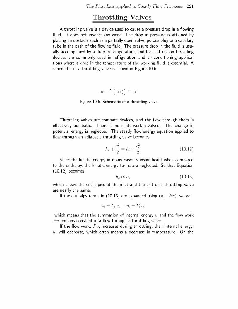
Throttling Valves
A throttling valve is a device used to cause a pressure drop in a flowingfluid. It does not involve any work. The drop in pressure is attained byplacing an obstacle such as a partially open valve, porous plug or a capillarytube in the path of the flowing fluid. The pressure drop in the fluid is usu-ally accompanied by a drop in temperature, and for that reason throttlingdevices are commonly used in refrigeration and air-conditioning applica-tions where a drop in the temperature of the working fluid is essential. Aschematic of a throttling valve is shown in Figure 10.6.
Figure 10.6 Schematic of a throttling valve.
i e
Throttling valves are compact devices, and the flow through them iseffectively adiabatic. There is no shaft work involved. The change inpotential energy is neglected. The steady flow energy equation applied toflow through an adiabatic throttling valve becomes
he +c2e
2= hi +
c2i
2(10.12)
Since the kinetic energy in many cases is insignificant when comparedto the enthalpy, the kinetic energy terms are neglected. So that Equation(10.12) becomes
he ≈ hi (10.13)
which shows the enthalpies at the inlet and the exit of a throttling valveare nearly the same.
If the enthalpy terms in (10.13) are expanded using (u + Pv), we get
ue + Pe ve = ui + Pi vi
which means that the summation of internal energy u and the flow workPv remains constant in a flow through a throttling valve.
If the flow work, Pv, increases during throttling, then internal energy,u, will decrease, which often means a decrease in temperature. On the
222 Chapter 10
contrary, if Pv decreases then u will increase, resulting in probable temper-ature increase. It means that the properties such as P , T and v of the fluidflowing through the throttling valve may change even though the enthalpyremains unchanged during throttling.
However, if the behaviour of the working fluid approximates that of anideal gas then no change in enthalpy means no change in temperature aswell.
Mixing Chambers
Mixing chamber refers to an arrangement where two or more fluidstreams are mixed to form one single fluid stream as shown in the schematicin Figure 10.7. Mixing chambers are very common engineering applicationsin process industries.
� �
Figure 10.7 Schematic of a mixing chamber.
�
i1
i2
e
Since a mixing chamber has more than one inlet, we use the steadyflow energy equation given by (10.4) to describe the flow through a mixingchamber. For the mixing chamber of Figure 10.7 with two inlets and oneexit, (10.4) becomes
Qin = mehe − (mi1hi1 + mi2hi2) (10.14)
Note that there is no shaft work in a mixing chamber, and the changesin kinetic and potential energies of the streams are usually neglected.
For the conservation of mass across the mixing chamber of Figure 10.7,we can write
me = mi1 + mi2
The First Law applied to Steady Flow Processes 223
which transforms (10.14) to
Qin = mi1(he − hi1) + mi2(he − hi2) (10.15)
Mixing chambers are usually well insulated, so that the process can betreated as adiabatic. For an adiabatic mixing chamber, (10.15) reduces to
mi1(he − hi1) = mi2(hi2 − he) (10.16)
Heat Exchangers
In the industries, there is often a need to cool a hot fluid stream beforeit is let out into the environment. The heat removed from cooling of a hotfluid can be used to heat another fluid that has to be heated up. This canbe achieved in a heat exchanger, which in general is a device where a hotfluid stream exchanges heat with a cold fluid stream without mixing witheach other. The simplest type is the double-pipe heat exchanger which hastwo concentric pipes of different diameters. One fluid flows in the inner pipeand the other in the annular space between the two pipes. The schematicof a double-pipe heat exchanger is shown in Figure 10.8.
Figure 10.8 Schematic of a double-pipe heat exchanger.
����
�
�
�
BiBe
Ai
Ae
Since a heat exchanger has two inlets and two exits, we use (10.4).There is no work transfer, and the changes in kinetic and potential energiesare neglected. Therefore, (10.4) reduces to
Since the mass flow rate of fluid A is the same at the inlet and at theexit, mAe = mAi, which may be represented by mA. Since the mass flow
224 Chapter 10
rate of fluid B is the same at the inlet and at the exit, mBe = mBi, whichmay be represented by mB Thus, (10.17) becomes
Qin = mA [hAe − hAi] + mB [hBe − hBi] (10.18)
Where a heat exchanger is insulated, it is adiabatic and the heat transferterm may be neglected. So that (10.18) reduces to
mfluid A
mfluid B
=(he − hi)fluid B
(hi − he)fluid A
(10.19)
Boilers and Condensers
A liquid is converted into vapour in a boiler by supplying heat to it.A boiler, for example, is used to heat water at room temperature to itsboiling temperature so that water may be converted into steam. Heat maybe supplied to the boiler by burning a fuel in the boiler. In a condenser, avapour is condensed to liquid by removing heat from it. Schematics of aboiler and a condenser are shown in Figure 10.9.
��
heat in
vapour out
liquid in
�
�
boiler
Figure 10.9 Schematics of a boiler and a condenser.
��
heat out
vapour in
liquid out ��
condenser
There is no shaft work involved in a boiler or a condenser. The potentialand kinetic changes across these devices are negligible in comparison to
The First Law applied to Steady Flow Processes 225
the change in enthalpy. So that the steady flow energy equation for flowthrough a boiler becomes
Qin = m (he − hi) (10.20)
and the steady flow energy equation for flow through a condenser be-comes
Qout = m (hi − he) (10.21)
10.7 Worked Examples
Example 10.1Gases produced during the combustion of a
fuel-air mixture, enter a nozzle at 200 kPa, 150◦C and 20 m/s and leavethe nozzle at 100 kPa and 100◦C. The exit area of the nozzle is 0.03 m2.Assume that these gases behave like an ideal gas with Cp = 1.15 kJ/kg ·Kand γ = 1.3, and that the flow of gases through the nozzle is steady andadiabatic. Determine (i) the exit velocity and (ii) the mass flow rate of thegases.
Solution to Example 10.1
(i) Determination of the exit velocity
The given flow may be satisfactorily described by (10.7). Since the behaviourof the gases is approximated to that of an ideal gas with constant Cp, (10.7)can be rewritten as
c2e − c2
i
2= Cp (Ti − Te) (10.22)
Substituting the values given in the problem statement in (10.22), we get
c2e
2=
202
2
(m
s
)2+
(1.15
kJ
kg ·K)
× (423 K − 373 K)
= 200(m
s
)2+ 57.5
(kJ
kg
).
226 Chapter 10
We cannot add a quantity in kJ/kg to a quantity in (m/s)2. But, we can adda quantity in J/kg to a quantity in (m/s)2 since they are equivalent as shownbelow:
J
kg=
N ·mkg
=kg ·m
s2m
kg=
(m
s
)2
Therefore,
ce =
√2 ×
[200
(m
s
)2+ 57.5 × 1000
(J
kg
)]= 339.7 m/s
Note that the speed of the gases flowing through the nozzle is increasedfrom 20 m/s to 339.7 m/s, which is achieved at the cost of the reduction in thegas pressure from 200 kPa to 100 kPa.
(ii) Determination of the mass flow rate of the gases
Assume that the gas flows perpendicular to a cross sectional area A at auniform speed c and at a uniform density ρ. The mass flow rate of the gasesthrough the given cross-section is then
m = A ρ c = A c/v (10.23)
where v is the specific volume.Since we assume ideal gas behaviour, the ideal gas equation of state may be
used to express v as
v =R T
P
Thus, the mass flow rate of an ideal gas through the cross-sectional area Acan be written as
m =A c P
R T(10.24)
As we know the exit area, exit pressure, exit velocity and exit temperature,and the gas constant R, calculated using R = (γ − 1)Cp/γ = 0.265 kJ/kg ·K,
m =(0.03 m2) × (339.7 m/s) × (100 kPa)
(0.265 kJ/kg ·K) × (373 K)= 10.31 kg/s
The First Law applied to Steady Flow Processes 227
Example 10.2Rework Example 10.1 assuming that the
expansion of the gases flowing through the nozzle from 200 kPa, 150◦Cand 20 m/s at the inlet to 100 kPa at the exit takes place quasistatically.
Solution to Example 10.2
(i) Determination of the exit velocity
Since the flow through the nozzle is assumed to be a quasistatic adiabaticflow of an ideal gas, P and T of the flow can be related using (7.31), whichgives
Te = Ti
(Pe
Pi
)(γ−1)/γ
= 423 K ×(
100200
)(1.3−1)/1.3
= 360.5 K
Substituting the values of ci, Ti and Te in (10.22), we get
ce =
√2 ×
[200
(m
s
)2+ 1.15 × (423 − 360.5) × 1000
(J
kg
)]= 379.7 m/s
Note that the speed of the gases flowing through the nozzle, expanding from200 kPa to 100 kPa, is increased from 20 m/s to 379.7 m/s when the flow isassumed to be quasistatic.
(ii) Determination of the mass flow rate of the gases
The mass flow rate of the gases through the nozzle is given by
m =(0.03 m2) × (379.7 m/s) × (100 kPa)
(0.265 kJ/kg ·K) × (360.5 K)= 11.92 kg/s
Student: Teacher, for an expansion or a compression process to be quasistatic,it must take place under fully restrained condition. Is that correct?
Teacher: Yes, that is correct.
228 Chapter 10
Student: It is stated in Example 10.2 that the expansion of the flow throughthe nozzle is assumed to be quasistatic. How could that be when there isnothing to restrain the expansion of the gases flowing through the nozzle?
Teacher: Yes, you are right about that. The flow through a nozzle is far fromquasistatic. However, we assume the flow to be quasistatic in order todetermine the maximum possible speed that could be attained by thegases flowing through the nozzle. Observe that the speed of the gasesat the exit is 379.7 m/s under quasistatic adiabatic condition, which setsthe maximum possible speed attainable by the gases flowing through thenozzle under the same inlet conditions and exit pressure.
Student: Oh... I see.
Teacher: It would be interesting to take look at the ratio between the actualkinetic energy change per kg of flow and the ideal kinetic energy changeper kg of flow achievable with quasistatic adiabatic flow under the samepressure difference between the inlet and the outlet of the nozzle and thesame inlet temperature.
The required ratio =[(c2
e − c2i )/2]actual
[(c2e − c2
i )/2]ideal
=(339.72 − 202)(379.72 − 202)
= 0.8
That is, the nozzle of Example 10.1 achieves only about 80% of the ki-netic energy increase per kg of flow achievable under ideal flow conditions.This way we determine the efficiency at which a nozzle operates.
Student: Okay, I see now why the flow is assumed to be quasistatic in Ex-ample 10.2. However, I have a question. How do you know that aquasistatic flow gives the maximum possible speed attainable by the gasflow through the nozzle?
Teacher: You are wrong. It is not the quasistatic flow, but the quasistaticadiabatic flow that gives the maximum possible speed attainable by thegas flow through the nozzle?
Student: Okay, Teacher. I still have a question. How do you know that aquasistatic adiabatic flow gives the maximum possible speed attainable bythe gas flow through the nozzle?
The First Law applied to Steady Flow Processes 229
Teacher: When learning the second law, you will see that it could be provedthat a quasistatic flow sets the limit for the best performance that couldbe expected of an engineering device operated under adiabatic conditions.
Example 10.3Rework Example 10.1 with steam flowing
through the nozzle.
Solution to Example 10.3
(i) The given flow can be described by (10.7), of which hi and he are the specificenthalpies of the steam at the inlet (2 bar and 150◦C) and at the exit (1 barand 100◦C). From a Steam Table, we find that hi = 2770 kJ/kg and he = 2676kJ/kg. Substituting these values in (10.7) along with ci = 20 m/s, we get
ce =
√2 ×
[200
(m
s
)2+ (2770 − 2676) × 1000
(J
kg
)]= 434 m/s
(ii) The mass flow rate of the steam may be calculated using (10.23) of whichthe specific volume v cannot be expressed as RT/P since the behaviour ofsteam may not be approximated by the ideal gas behaviour. However, it is nota problem because v for steam can be obtained from a Steam Table. We knowthe cross-sectional area and the speed of steam at the exit. We can get v at theexit at 1 bar and 100◦C from the Steam Table as 1.696 m3/kg. Substitutingthese values in (10.23), we get
m =(0.03 m2) × (434 m/s)
1.696 m3/kg= 7.68 kg/s
230 Chapter 10
Example 10.4Steam entering a nozzle at 7 bar and 250◦C
with a velocity of 10 m/s, leaves it at 3 bar 200◦C with a velocity of 262m/s. Determine the heat lost by the steam flowing through the nozzle.If the mass flow rate of the steam flowing through the nozzle is 2.5 kg/s,determine the inlet area of the nozzle.
Solution to Example 10.4
The given flow can be described by (10.6), of which hi and he are the specificenthalpies of the steam at the inlet (7 bar and 250◦C) and at the exit (3 barand 200◦C). From a Steam Table, we find that hi = 2955 kJ/kg and he = 2866kJ/kg. Substituting these values in (10.6) along with ci = 10 m/s and ce = 262m/s, we get
Qin = 2.5kg
s×
[(2866 − 2955) × 1000
(J
kg
)+
2622 − 102
2
(m
s
)2]
= −136.8 kJ
The heat lost by the steam flowing through the nozzle is 136.8 kJ.
The inlet area of the nozzle can be calculated using (10.23) as follows:
Ai =m vi
ci
where m = 2.5 kg/s, ci = 10 m/s and vi = v at 7 bar and 250◦C = 0.3364m3/kg. The inlet area of the nozzle is therefore 0.0841 m2.
an adiabatic diffuser at 85 kPa and 250 K at a steady speed of 265 m/s andleaves it at 15 m/s. Assuming ideal gas behaviour for air with constantspecific heats, determine the pressure and temperature of the air at thediffuser exit.
The First Law applied to Steady Flow Processes 231
Solution to Example 10.5
Equation (10.7) applied to the air flow through the adiabatic diffuser assum-ing ideal gas behaviour gives (10.22). Substituting the given numerical valuesknown from the problem statement in (10.22), we get
Te = 250 K −(
152 − 2652
2 × 1005
)(m/s)2
J/kg ·K = 284.8 K (10.25)
which gives the temperature of air at the diffuser exit.
To determine the pressure at the exit, there is not enough data provided.However, if we assume quasistatic flow through the diffuser then, since the flowis adiabatic and since ideal gas behaviour is assumed, P and T of the flow canbe related using (7.31), which gives
Pe = Pi
(Te
Ti
)γ/(γ−1)
= 85 kPa ×(
284.8250
)1.4/(1.4−1)
= 134 kPa
which gives the pressure of air at the diffuser exit under ideal conditions.
That is, under quasistatic adiabatic flow conditions, the air flowing throughthe diffuser is compressed from 85 kPa to 134 kPa, which is achieved at the costof the reduction in the air speed from 265 m/s to 15 m/s.
Example 10.6A mixture of gases enter a nozzle at 2.5 bar
and 237◦C with a speed of 20 m/s. The inlet diameter of the nozzle is0.45 m. We are required to achieve an exit velocity of 340 m/s. Assumingquasistatic flow conditions through the nozzle, determine (i) the pressurethat should be maintained at the nozzle exit and (ii) the exit diameter.Take Cp = 1.15 kJ/kg ·K and γ = 1.3 for the gases. Assume ideal gasbehaviour and steady adiabatic flow through the nozzle.
Solution to Example 10.6
(i) Since the flow is assumed to be a quasistatic adiabatic flow of an ideal gas
232 Chapter 10
(7.31) could be used to determine the pressure at the nozzle exit as follows:
Pe = 2.5 bar ×(
Te
510
)1.3/(1.3−1)
(10.26)
where the exit temperature Te is unknown.For the flow of gases, assumed to behave as an ideal gas, through an adiabatic
nozzle, (10.7) is applicable. Substituting the values known from the problemstatement in (10.7), we get
1.15(
kJ
kg ·K)
(Te − 510 K) +(
3402 − 202
2
)(m
s
)2= 0
which gives Te = 460 K.Substituting this value of Te in (10.26) we get Pe = 1.6 bar. That is, an
exit pressure of about 1.6 bar should be maintained for the combustion gases tobe able to reach the speed of 340 m/s2 at the exit.
(ii) To determine the exit area, we use (10.24) as follows:
m =(
A c P
R T
)inlet
=(
A c P
R T
)exit
which gives
Ae = Ai
(Pi
Pe
) (ci
ce
) (Te
Ti
)= Ai
(2.51.6
) (20340
) (460510
)= 0.083Ai
Since Ai = (π/4)(0.45 m)2 = 0.159 m2, the exit area of the nozzle is about
0.013 m2, and the exit diameter of the nozzle is about 0.13 m.
Example 10.7A gas turbine is operated with gases (Cp =
0.992 kJ/kg ·K and γ = 1.29) entering it at 10 bar and 1025◦C, andleaving it at 1 bar and 550◦C. Assuming adiabatic flow through the turbine,calculate the power output of the turbine (in MW) for each kg per secondof gases flowing through the turbine.
If 120 MW of power is to be produced by the turbine, determine themass flow rate of gases flowing through the turbine.
The First Law applied to Steady Flow Processes 233
Solution to Example 10.7
Equation (10.9) can be used to describe the behaviour of the gases flowingthrough the adiabatic turbine for which Qin = 0. Since ideal gas behaviour isassumed (10.9) becomes
(Ws)out = mCp (Ti − Te)
Substituting the known numerical values in the above equation, we get
(Ws)out = m × 0.992kJ
kg ·K × (1025 − 550) K = m × 471.2 kJ/kg
which gives
(Ws)out
m= 471.2
kJ
kg= 471.2
kJ/s
kg/s= 471.2
kW
kg/s= 0.4712
MW
kg/s
The power output of the turbine is therefore 0.4712 MW for each kg persecond of gases flowing through the turbine.
Mass flow rate of gases required to produce 120 MW of power is calculatedas follows:
m =120 MW
0.4712 MW/kg/s= 254.7 kg/s
Example 10.8Rework Example 10.7 under quasistatic
adiabatic conditions, where the gases are supplied to the turbine at 10bar and 1025◦C, and they leave it at 1 bar.
Solution to Example 10.8
Ideal gas flow through the turbine under quasistatic adiabatic condition canbe described by (7.31) so that
Te = (1025 + 273) K ×(
110
)(1.29−1)/1.29
= 773.5 K = 500.5◦C
234 Chapter 10
Therefore
(Ws)out
m= 0.992
kJ
kg ·K × (1025 − 500.5) K
= 520.3 kJ/kg
which gives that the power produced by the turbine under quasistatic adiabaticflow condition is 0.5203 MW for each kg per second of gases flowing throughthe turbine.
Mass flow rate of gases required to produce 120 MW of power is calculatedas follows:
m =120 MW
0.5203 MW/kg/s= 230.6 kg/s
Observe that the turbine operating under quasistatic adiabatic conditionproduces more power, as in Example 10.8, which is 0.5203 MW, than thepower produced by the turbine working under adiabatic but non-quasistaticcondition, as in Example 10.7, for the same inlet condition and the exitpressure. The efficiency of the turbine in Example 10.7, can thereforebe calculated as 0.4712/0.5203 = 90.6%.
Also, observe that the mass flow rate of the gas required to produce thesame power output from the turbine operating under the same inlet condi-tion and the exit pressure is less for the quasistatic adiabatic flow throughthe turbine, as in Example 10.8, than for the non-quasistatic adiabaticflow through the turbine, as in Example 10.7.
Example 10.9A steam turbine producing 55 MW power is
fed with steam at 70 bar and 500◦C. Steam leaves the turbine at 0.08 barwith a dryness fraction of 0.90. Determine the mass flow rate of steamthrough the adiabatic turbine.
The First Law applied to Steady Flow Processes 235
Solution to Example 10.9
Equation (10.9) can be used to describe the behaviour of steam flowingthrough the adiabatic turbine, where (Ws)out = 55 MW, and hi is the enthalpyat 70 bar and 500◦C and he is the enthalpy at 0.08 bar for a dryness fraction of0.90. From a Superheated Steam Table, we find that hi = 3410 kJ/kg. From aSaturated Water and Steam Table, we find that
Substituting the known numerical values in (10.9), we get
55 × 103 kJ
s= m × (3410 − 2336)
kJ
kg
which gives m, which is the mass flow rate of steam through the adiabatic
turbine, as 51.2 kg/s.
Example 10.10A steam turbine is fed with 53 kg/s of high
pressure steam at 70 bar and 500◦C and with 10 kg/s of low pressuresteam at 6 bar and 250◦C. The steam leaving the turbine is at 0.07 barwith the dryness fraction of 0.92. Determine the power produced by thesteam turbine considering the fact that the heat loses from the turbine isequivalent to 2% of the power production.
Solution to Example 10.10
The schematic of the steam turbine given is shown in Figure 10.10. Since theturbine has two inlets and one exit, we must use the steady flow energy equationapplied for a multiple-stream steady flow process given by (10.4). Neglectingthe changes in potential and kinetic energies reduces (10.4) applied to the givensystem to
(Q)in + (Ws)in = me he − mi1 hi1 − mi2 hi2
236 Chapter 10
Since the power output is positive for a turbine and since heat is lost to thesurroundings, the above equation can be rewritten as
(Q)out + (Ws)out = mi1 hi1 + mi2 hi2 − me he (10.27)
where (Q)out is given as 2% of (Ws)out.
�
Figure 10.10 Schematic of the turbine of Example 10.10.
e
�i2
i1
i2 is low pressure steam at 6 bar and 250◦Ci1 is high pressure steam at 70 bar and 500◦C
e is steam at 0.07 bar and x = 0.92
�
From a Superheated Steam Table, we can find that the enthalpy of the highpressure steam hi1 = 3410 kJ/kg and the enthalpy of the low pressure steamhi2 = 2958 kJ/kg. From a Saturated Water and Steam Table, we can find thatthe enthalpy of the steam leaving the turbine he = 163 kJ/kg + 0.92 × 2409kJ/kg = 2379 kJ/kg. The mass flow rates are given as mi1 = 53 kg/s and mi2
= 10 kg/s.The mass balance applied for a multiple-stream steady flow process is given
by (10.5), which for the given system becomes
me = mi1 + mi2 = (53 + 10) kg/s = 63 kg/s
Substituting the known numerical values in (10.27), we get
That is, the steam turbine power output is 59.25 MW, and the heat lost tothe surroundings is about 1.18 MJ/s.
The First Law applied to Steady Flow Processes 237
Example 10.11Air at 100 kPa and 300 K with a mass flow
rate of 0.05 kg/s is to be compressed to 800 kPa using any one of thefollowing methods:
Method 1: Quasistatic adiabatic compression from 100 kPa to 800 kPain a single compressor.
Method 2: Quasistatic adiabatic compression from 100 kPa to 250 kPain one compressor followed by quasistatic adiabatic compression from250 kPa to 800 kPa in a second compressor.
Method 3: Quasistatic adiabatic compression from 100 kPa to 250 kPain one compressor followed by constant pressure cooling to 300 K at250 kPa, and then quasistatic adiabatic compression from 250 kPato 800 kPa in a second compressor.
Determine the method in which the total power requirement is the lowest.
Solution to Example 10.11
Method 1:Applying (10.11) to the first compressor operated adiabatically, assuming
that air behaves as an ideal gas, we get
(Ws)in = mCp (Te − Ti) (10.28)
Substituting the numerical data in the problem and the properties of air fromTable 5.2 in (10.28), we get
(Ws)in =(
0.05kg
s
) (1.005
kJ
kg ·K)
(Te − 300) K
where Te is unknown. Since the flow is taken to be quasistatic adiabatic, wecan use (7.31) to determine Te as follows:
Te = Ti
(Pe
Pi
)(γ−1)/γ
= 300 K ×(
800100
)(1.4−1)/1.4
= 543.4 K
Therefore,(Ws)in = 12.23 kJ/s = 12.23 kW
That is, the power requirement of a single compressor to adiabatically andquasistatically compress air at 100 kPa and 300 K to 800 kPa is 12.23 kW.
238 Chapter 10
Method 2:Here, air is compressed to 250 kPa in one compressor, and the hot air
leaving it is compressed in a second compressor to 800 kPa. Both compressionsare quasistatic adiabatic. The power requirement of the first compressor can beworked out in a manner similar to that is described under Method 1, except forthe fact that the exit pressure is now 250 kPa, not 800 kPa. Therefore, we getthe exit temperature as
Te = Ti
(Pe
Pi
)(γ−1)/γ
= 300 K ×(
250100
)(1.4−1)/1.4
= 389.8 K
Substituting the numerical value of Te in (10.28), we get (Ws)in = 4.51 kW.The second compressor works in a way very similar to the first, except for
that the inlet pressure is 250 kPa, the inlet temperature is 389.8 K, and theexit pressure is 800 kPa. Therefore, we get the exit temperature of the secondcompressor as
Te = 389.8 K ×(
800250
)(1.4−1)/1.4
= 543.5 K
The power requirement of the second compressor, evaluated using (10.28),is (Ws)in = 7.72 kJ/s = 7.72 kW.
The total power requirement of the two compressors is obtained by adding4.51 kW to 7.72 kW, which is 12.23 kW.
Method 3:The first compressor here is similar to the first compressor in Method 2, and
it’s power requirement is 4.51 kW. The second compressor here has an inlettemperature of 300 K, and
Te = 300 K ×(
800250
)(1.4−1)/1.4
= 418.3 K
and the power consumption, evaluated using (10.28), is 5.94 kW.The total power requirement of the two compressors is obtained by adding
4.51 kW to 5.94 kW, which is therefore 10.45 kW.
The total power consumptions are the same for Method 1 and for Method
2. The total power consumption is the lowest for Method 3, in which the hot
air exiting the first compressor is cooled to 300 K before it is fed to the second
compressor. Method 3 uses the practice known as multi-stage compressionwith intercooling in order to decrease the work required to compress the gas
between two specified pressures.
The First Law applied to Steady Flow Processes 239
Example 10.12An ideal gas is compressed by an adiabatic
compressor in a steady-flow process, and cooled to its initial temperature.The potential and kinetic energy changes are negligible. Compare the heatremoved from the gas in the cooler with the work done on the gas by thecompressor.
Solution to Example 10.12
The schematic of the given system is shown in Figure 10.11.
cooler
T1
T2 T1
Figure 10.11 Schematic for Example 10.12.
����
(Ws)inQout
Equation (10.11) applied to the ideal gas flow through the adiabatic com-pressor becomes
(Ws)in = mCp (T2 − T1) (10.29)
where T1 and T2 are the respective inlet and exit temperatures of the gas flowingthrough the compressor, as shown in Figure 10.11.
The term (Ws)in is a positive quantity since work is always done on the gasby the compressor. Consequently, the gas temperature T2 at the compressorexit is always larger than the temperature T1 at the inlet. The gas leaving thecompressor at T2 is cooled to its initial temperature T1 in a cooler. The steadyflow energy equation (10.3), when applied to the cooler becomes
Qin = m (he − hi)
since there is no work exchange and since the potential and kinetic energychanges are neglected.
For an ideal gas, the above equation becomes Qin = mCp (T1 − T2). Sincethe cooler exit temperature T1 is less than the inlet temperature T2, the above
240 Chapter 10
equation can be rewritten as
Qout = mCp (T2 − T1) (10.30)
which is a positive quantity.
Combining (10.29) and (10.30), we get (Ws)in = Qout. That is, the work
done on the gas by the compressor equals the heat removed from the gas in the
cooler under the conditions stated in the problem.
Example 10.13A pump is used to increase the pressure of
25 kg/s of saturated water at 0.07 bar entering the pump to 100 bar and40◦C. Determine the power input to the pump assuming adiabatic flowthrough the pump.
Solution to Example 10.13
Neglecting the potential and kinetic energy changes, the power input to
the adiabatic pump can be determined using (10.11), where hi is the specific
enthalpy of saturated water at 0.07 bar and he is the specific enthalpy at 50
bar and 40◦C. From a Saturated Water and Steam Table, we find hi = 163
kJ/kg. The water leaving the pump is at compressed state at 100 bar. From a
Compressed Water Table∗, we find he = 176 kJ/kg. Substituting the numerical
values known in (10.11), the power input of the pump can be calculated as
Win = 25 × (176 − 163) kJ/s = 325 kW.
Example 10.14Wet steam at 7 bar is throttled adiabatically
to 1 bar and 110◦C. Determine the dryness fraction of the wet steam at 7bar.
∗Table A-7 of Cengel, Y.A. & Boles, M.A. 1998 Thermodynamics: an engineeringapproach, 3rd Edition, McGraw-Hill International Editions.
The First Law applied to Steady Flow Processes 241
Solution to Example 10.14
Steam flow through the adiabatic throttling valve can be expressed by (10.13)which states that the specific enthalpies at the inlet hi and at the exit he arenearly the same. The value of he at 1 bar and 110◦C can be obtained from aSuperheated Steam Table as 2696 kJ/kg. According to (10.13), the value of hi
at 7 bar is the same as 2696 kJ/kg. At 7 bar, a Saturated Water and SteamTable gives hf = 697 kJ/kg and hg = 2764 kJ/kg. Therefore, the drynessfraction of the wet steam at 7 bar can be calculated as
x =he − hf
hg − hf=
2696 − 6972764 − 697
= 0.967 = 96.7%
Example 10.15Water flowing at 5 bar and 120◦C is mixed
with superheated steam flowing at 10 bar and 200◦C in an adiabatic mixingchamber to produce saturated water at 8 bar. Determine the ratio of themass flow rates of water and the superheated steam, neglecting the changesin kinetic and potential energies.
Solution to Example 10.15
The steady flow energy equation applied to the adiabatic mixing chambershown in Figure 10.7, neglecting the changes in potential and kinetic energies, isgiven by (10.16), where i1 denotes the water entering the mixing chamber at 5bar and 120◦C, i2 denotes the superheated steam entering the mixing chamberat 10 bar and 200◦C, and e denotes the saturated steam leaving the mixingchamber at 8 bar.
The water at 5 bar and 120◦C is at compressed state. Since the pressure is5 bar, we use the approximate method discussed in the Solution to Example(6.8) to determine hi1. In this method, we approximate hi1 to the saturatedwater specific enthalpy at 120◦C, which is 504 kJ/kg as read from a SaturatedWater and Steam Table.
The superheated steam specific enthalpy hi2 is directly read from a Super-heated Steam Table as 2829 kJ/kg at 10 bar and 200◦C. The saturated water
242 Chapter 10
specific enthalpy he is directly read from a Saturated Water and Steam Table as721 kJ/kg at 8 bar.
Substituting the known numerical values in (10.16), we can determine theratio of the mass flow rate of water to the mass flow rate of superheated steamas
mi1
mi2=
hi2 − he
he − hi1=
2829 − 721721 − 504
= 9.7
Example 10.16A gas (γ = 1.3) fed to a turbine at 10
bar and 370◦C, is assumed to expand quasistatically and adiabatically to 4bar as it flows through the turbine. The gas stream exiting the turbine ismixed with a second stream of the same gas flowing at 4 bar and 38◦C, inan adiabatic mixing chamber. The mass flow rate of the gas through theturbine is 4 times the mass flow rate of the second gas stream. Determinethe temperature of the gas leaving the mixing chamber at 4 bar, neglectingthe changes in kinetic and potential energies and assuming that the gasconcerned behaves as an ideal gas.
Solution to Example 10.16
The schematic of the given system is shown in Figure 10.12. The tem-perature of the gas leaving the mixing chamber is to be found, which is thetemperature of the gas stream labeled 4 in Figure 10.12.
2 4
1����
���� ����
Figure 10.12 Schematic of the system given in Example 10.16.
��
� ��
��3gas at 10 bar & 643 K
gas at 4 bar & 311 K
The First Law applied to Steady Flow Processes 243
The steady flow energy equation applied to the gas flow through an adiabaticmixing chamber with negligible changes in the potential and kinetic energies,given by (10.16), becomes
m2 (h4 − h2) = m3 (h3 − h4)
which is written in accordance with the stream labels shown on Figure 10.12.Since the gas is assumed to behave as an ideal gas, the above equation
becomesm2 Cp (T4 − T2) = m3 Cp (T3 − T4)
which yields
T4 =m2 T2 + m3 T3
m2 + m3(10.31)
To find T4, we need the value of each and every term on the right-hand sideof (10.31).
First of all note that m2 is the mass flow rate through the turbine, and thatm3 is the mass flow rate of the second gas stream. It is given that the massflow rate of the gas stream through the turbine is 4 times the mass flow rate ofthe second gas stream. Therefore, m2 = 4 m3, which reduces (10.31) to
T4 =4 T2 + T3
5=
4 T2 + 311 K
5(10.32)
since T3 = 311 K.We need to find T2, which is the temperature of the exit gas stream from the
turbine. The flow through the turbine is assumed to be quasistatic adiabatic,and therefore (7.31) can be used to find T2 as follows:
T2 = T1
(P2
P1
)(γ−1)/γ
= 643 K ×(
410
)(1.3−1)/1.3
= 520.5 K = 247.5◦C
Substituting T2 = 520.5 K in (10.32), we get T4 = 478.6 K = 205.6◦C.
Note that the second gas stream is heated from 38◦C to 205.6◦C by mixing
it with the turbine exit at 247.5◦C.
Example 10.17Air (Cp = 1.005 kJ/kg ·K and γ = 1.4) is
heated as it flows steadily through a pipe of uniform cross-sectional area150 cm2. It enters at 300 kPa and 345 K with a velocity of 25 m/s and
244 Chapter 10
leaves at 200 kPa and 800 K, and may be assumed to behave as an idealgas. Determine the amount of heat added per kilogram of air.
If this amount of heat is supplied to 1 kg of air in a closed rigid containerat 300 kPa and 345 K, what will be the final temperature and pressure ofair in the container?
Solution to Example 10.17
The steady flow energy equation (10.3) applied to the pipe flow yields
Qin = m
(he − hi +
c2e − c2
i
2
)
since there is no work exchange or potential energy change.Substituting the given numerical values in the above equation with the as-
sumption that air behaves as an ideal gas, we get
Qin
m=
[1005
J
kg ·K × (800 − 345) K +c2e − 252
2
(m
s
)2]
(10.33)
where the exit velocity ce is unknown.To determine the exit velocity, let us use the fact that the flow is steady, and
therefore the mass flow rate is the same at the inlet and the exit. Thus (10.24)gives
ce =(
Ai
Ae
) (Pi
Pe
) (Te
Ti
)ci =
(150150
) (300200
) (800345
)25 m/s = 87 m/s
Substituting ce = 87 m/s in (10.33), we get Qin = 460.75 kJ per kg of airflowing through the pipe.
The second part of the problem states that 460.75 kJ/kg of heat is suppliedto air in a closed rigid container at 300 kPa and 345 K. Suppose the mass of airin the close container is m, then Qin = 460.75 m kJ. Therefore, the first lawapplied to the given closed system yields,
460.75 m = ΔU
since no work is supplied to the air in the closed rigid container. Since air istaken as an ideal gas, we get
ΔU = mCv (Tf − Ti)
The First Law applied to Steady Flow Processes 245
Therefore,460.75 m = m 0.718 (Tf − 345)
which gives Tf = 986.7 K.The pressure in the closed container can be obtained using the ideal gas
equation of state for the given closed system as follows:
m =Pf Vf
R Tf=
Pi Vi
R Ti
Since Vf = Vi for the closed rigid container, we get
Pf = Pi
(Tf
Ti
)= 300 kPa
(986.7345
)= 858 kPa
Note that when the same amount of heat is provided, the temperature and
pressure increases in the closed system are far greater than those in the open
system. You may try to figure out why it is so as an exercise.
Example 10.18Compressed air is preheated in a shell-and-
tube heat exchanger, shown in Figure 10.13, before it enters the combustionchamber.
Figure 10.13 Schematic of a heat exchanger of Example 10.18.
air at Te◦C
air at 200◦C
gases at 550◦C
gases at 250◦C
����
����
�
�
�
�
It enters the heat exchanger at 9 bar and 200◦C with a mass flow rate of16 kg/s. It gains heat from the exhaust gases leaving a turbine. Exhaust
246 Chapter 10
gases enter the heat exchanger at 1.4 bar and 550◦C and leave at 1.2 barand 250◦C at a mass flow rate of 17 kg/s. Assume that Cp for the exhaustgases are the same as that for air and that the heat exchanger operatesunder adiabatic conditions. Determine the exit temperature of the air andthe amount of heat transferred from the exhaust gases to the air.
Solution to Example 10.18
For an adiabatic heat exchanger with two fluid streams, (10.19) can be used.Taking the exhaust gases as A and the compressed air as B and assuming idealgas behaviour, (10.19) can be rewritten as
mexhaust gases
mair=
(he − hi)air
(hi − he)exhaust gases=
(Te − Ti)air
(Ti − Te)exhaust gases
since Cp for the exhaust gases is assumed to be the same as that for the air.Substituting the numerical values known in the above equation, we get
1716
=Te − 200550 − 250
(10.34)
which gives the exit temperature of air Te as 519◦C.To determine the heat transferred from the exhaust gases to the air, let us
apply the steady flow energy equation (10.3) to one of the streams. For air,
Example 10.19Rework Example 10.18 with a mass flow
rate of air taken as of 14 kg/s, and comment on your results.
Solution to Example 10.19
Replacing 16 in (10.34) by 14, we get
1714
=Te − 200550 − 250
(10.35)
The First Law applied to Steady Flow Processes 247
which gives the exit air temperature Te as 564◦C.
The exit air temperature of 564◦C is greater than the temperature of the
exhaust gases entering the heat exchanger, which is 550◦C. Since the air leaving
the heat exchanger is receiving heat from the exhaust gases entering the heat
exchanger, the exhaust gas temperature must always be greater than the air
temperature. Therefore, the answer we got is unrealistic. Thus, we conclude
that the mass flow rate of air should not be as low as 14 kg/s.
10.8 Summary
• A steady flow process with a single-stream flowing through the system isdescribed by
mi = me (10.1)
and by
Qin + (Ws)in = m
[he − hi +
c2e − c2
i
2+ g (ze − zi]
](10.3)
which is the steady flow energy equation (abbreviated to SFEE) for asingle-stream process.
• For a multiple-stream steady flow process, that is, a system with manyinlets and many exits for mass to flow in and out of the system, the steadyflow energy equation (SFEE) becomes
Qin + (Ws)in =[me1
(he1 +
c2e1
2+ gze1
)]
+[me2
(he2 +
c2e2
2+ gze2
)]+ · · ·
−[mi1
(hi1 +
c2i1
2+ gzi1
)]
−[mi2
(hi2 +
c2i2
2+ gzi2
)]− · · ·(10.4)
which is solved together with the mass balance for a multiple-streamsteady flow process,
me1 + me1 + · · · = mi1 + mi2 + · · · (10.5)
248 Chapter 10
where the subscripts e1, e2, · · · denote exit 1, exit 2, and so on, respec-tively, and the subscripts i1, i2, · · · denote inlet 1, inlet 2, and so on,respectively.
• We can add a quantity in J/kg to a quantity in (m/s)2 since they areequivalent as shown below:
J
kg=
N ·mkg
=kg ·m
s2m
kg=
(m
s
)2
• Assume that a fluid flows perpendicular to a cross section with a cross-sectional area A, at a uniform speed c and at a uniform density ρ. Themass flow rate of the fluid through the cross-sectional area A is then
m = A ρ c =Ac
v(10.23)
where v is the specific volume.
If the fluid were steam or a mixture of water and steam, v could be foundfrom the Steam Table.
If the fluid were assumed to behave as an ideal gas, then the ideal gasequation of state would give v = R T/P . Therefore, the mass flow rateof an ideal gas through the cross-sectional area A is