ACTIVITY REPORT 2017 088 electron microscope in biological investigations. As the location of functional proteins in a cell cannot be identified directly from SXT images, it is important to have a fluorescence microscope to complement SXT to image a cell in a region of interest. 4-6 Herein, we adopted a high-resolution fluorescence structured- il- lumination microscope (SIM) that is correlated online with the SXT to derive from a biological specimen the desired structural and functional information. The light path of the fluorescence SIM is 70º off the beam of the SXT. Figure 3 shows a photograph of a cor- relation of SXT and fluorescence SIM; that correlative system is inside the vacuum chamber. To prevent radi- ation damage, a sample and its environment should be kept under cryogenic conditions, for which reason samples must be prepared by quick freezing using either a plunge freezer or a high-pressure freezer to avoid the formation of ice crystals. Some biomedical subjects can be implemented, including an investi- gation of molecular events within cells, changes in cellular architecture, interaction or communication between cells, interaction between host and microor- ganisms, and structural changes of tissue. The con- struction of the beamline and end station in energy range 200–1,200 eV is complete; the commissioning began from the end of 2017. (Reported by Lee-Jene Lai ) References 1. C. A. Larabell, and K. A. Nugent, Curr Opin Struct Biol. 20, 623 (2010). 2. G. Schneider, P. Guttmann. S. Rehbein, S. Werner, and R. Follath, J. Struct. Biol. 177, 212 (2012). 3. E. Pereiro, J. Nicolás, S. Ferrer, and M. R. Howells, J. Synchrotron. Rad. 16, 505 (2009). 4. C. Hagen, P. Guttmann, B. Klupp, S.Werner, S. Rehbein, T.C. Mettenleiter, G. Schneider, and K. Grunewald, J. Struct. Biol. 177, 193 (2012). 5. E. M. H. Duke, M. Razi, A. Weston, P. Guttmann, S. Werner, K. Henzler, G. Schneider, S. A. Tooze, and L. M. Collinson, Ultramicroscopy 143, 77 (2014). 5. H. Y. Chen, D. M. L. Chiang, Z. J. Lin, C. C. Hsieh, G. C. Yin, I. C. Weng, P. Guttmann, S. Werner, K. Henzler, G. Schneider, L. J. Lai, and F. T. Liu, Sci Rep. 6, 34879 (2016). Fig. 3: Fluorescence SIM correlation with SXT inside the SXT chamber The Installation of the Instrument for Bragg Coher- ent Diffraction Imaging A real-space image is more interesting than a one-dimensional reduction scattering profile with a model fitting curve. However, the resolution of the image is subject to the optics for the traditional X-ray microscopies. The lensless imaging technique, coher- ent X-ray diffraction imaging (CXDI), can overcome the resolution limit affected by the optics, but its de- velopment is limited by the coherent X-ray beam qual- ity. The implementation of coherent X-ray scattering techniques has been initiated since high brightness synchrotron sources started producing highly coher- ent X-ray beams. The Coherent X-ray Scattering (CXS) Beamline, TPS 25A, is one of the dedicated beamlines designed for the coherent X-ray scattering experi- ments and it has been opened to users. In traditional microscopies, the optics is used to obtain the images.
Transcript
Facility Status
ACTIV
ITY REPO
RT 2017
088
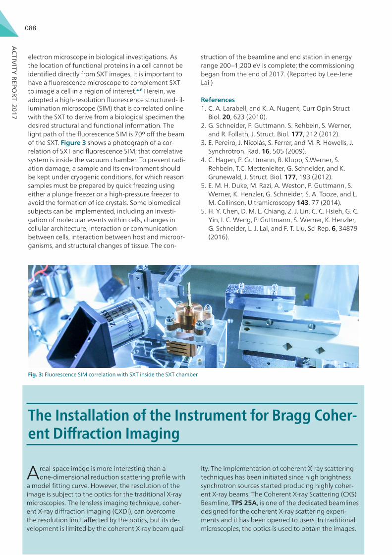
electron microscope in biological investigations. As the location of functional proteins in a cell cannot be identified directly from SXT images, it is important to have a fluorescence microscope to complement SXT to image a cell in a region of interest.4-6 Herein, we adopted a high-resolution fluorescence structured- il-lumination microscope (SIM) that is correlated online with the SXT to derive from a biological specimen the desired structural and functional information. The light path of the fluorescence SIM is 70º off the beam of the SXT. Figure 3 shows a photograph of a cor-relation of SXT and fluorescence SIM; that correlative system is inside the vacuum chamber. To prevent radi-ation damage, a sample and its environment should be kept under cryogenic conditions, for which reason samples must be prepared by quick freezing using either a plunge freezer or a high-pressure freezer to avoid the formation of ice crystals. Some biomedical subjects can be implemented, including an investi-gation of molecular events within cells, changes in cellular architecture, interaction or communication between cells, interaction between host and microor-ganisms, and structural changes of tissue. The con-
struction of the beamline and end station in energy range 200–1,200 eV is complete; the commissioning began from the end of 2017. (Reported by Lee-Jene Lai )
References 1. C. A. Larabell, and K. A. Nugent, Curr Opin Struct
Biol. 20, 623 (2010).2. G. Schneider, P. Guttmann. S. Rehbein, S. Werner,
and R. Follath, J. Struct. Biol. 177, 212 (2012).3. E. Pereiro, J. Nicolás, S. Ferrer, and M. R. Howells, J.
Synchrotron. Rad. 16, 505 (2009).4. C. Hagen, P. Guttmann, B. Klupp, S.Werner, S.
Rehbein, T.C. Mettenleiter, G. Schneider, and K. Grunewald, J. Struct. Biol. 177, 193 (2012).
5. E. M. H. Duke, M. Razi, A. Weston, P. Guttmann, S. Werner, K. Henzler, G. Schneider, S. A. Tooze, and L. M. Collinson, Ultramicroscopy 143, 77 (2014).
5. H. Y. Chen, D. M. L. Chiang, Z. J. Lin, C. C. Hsieh, G. C. Yin, I. C. Weng, P. Guttmann, S. Werner, K. Henzler, G. Schneider, L. J. Lai, and F. T. Liu, Sci Rep. 6, 34879 (2016).
Fig. 3: Fluorescence SIM correlation with SXT inside the SXT chamber
The Installation of the Instrument for Bragg Coher-ent Diffraction Imaging
A real-space image is more interesting than a one-dimensional reduction scattering profile with
a model fitting curve. However, the resolution of the image is subject to the optics for the traditional X-ray microscopies. The lensless imaging technique, coher-ent X-ray diffraction imaging (CXDI), can overcome the resolution limit affected by the optics, but its de-velopment is limited by the coherent X-ray beam qual-
ity. The implementation of coherent X-ray scattering techniques has been initiated since high brightness synchrotron sources started producing highly coher-ent X-ray beams. The Coherent X-ray Scattering (CXS) Beamline, TPS 25A, is one of the dedicated beamlines designed for the coherent X-ray scattering experi-ments and it has been opened to users. In traditional microscopies, the optics is used to obtain the images.
Facility Status
ACTIV
ITY REPO
RT 2017
089
Therefore the resolution corresponds to the quality of the optics. The high resolution imaging techniques to reveal the fine details of the microstructure are widely applied in physics, chemistry, or biology. Currently the spatial resolution achieved in the X-ray microscopies is around 10 nm,1 and there is room for improving the diffraction limit. Because of the technical limitation of optics manufacturing, CXDI is one of the alternative methods to extend the resolution beyond the dif-fraction limit. Different from the traditional imaging techniques, CXDI uses the phase retrieval algorithm to reconstruct the real-space image of an object from its coherent X-ray scattering pattern in the recipro-cal space.2 The resolution of the real-space image depends on the quality of the coherent scattering pattern collected from the experiments. To cope with different samples and experimental conditions, CXDI can also be performed in both transmission and reflection geometries. There are some other transfor-mations and extensions of CXDI such as Fresnel CXDI, Bragg CXDI, plane-wave CXDI and psychographic CXDI.3-5
Bragg CXDI is a promising tool for materials science studies. When the nanocrystals are illuminated by the coherent X-ray photon beam, the 2D profile of the Bragg diffraction peaks are recorded by an area detector. Due to the confinement effect the crystal could be highly strained in nanoscale. Conventionally X-ray diffraction is employed to analyze the strain. The result of the Bragg CXDI for the strain analysis can provide further information including the ions displaced from the reference lattice, which induces the phase shift of the diffraction beams. Consequent-ly the diffraction peak profiles would be varied. The coherent diffraction patterns of the strain crystals can be treated as a kind of interference pattern. Through the phase retrieval algorithm the image of the object can be reconstructed from the Bragg CXDI patterns. The phase of the reconstructed image implies the information of the strains or the ion displacements in the crystals. By collecting several Bragg reflections of the nanocrystal, the full strain tensor in the nano-crystal could also be determined.6 Based on the initial plan of the CXS beamline, the beamline design is for the experiments in the small q range; nevertheless the new demand for the Bragg geometry CXDI of the nanocrystal studies is increasing. The function of the Bragg CXDI was decided to be added on the CXS beamline and the installation has been accomplished.
The design concept of the instrument for the Bragg coherent diffraction imaging on the CXS beamline is to have a secondary detection system with a motor-ized stage for the angular movement. The rotation center of the stage is on the focal point of the X-ray
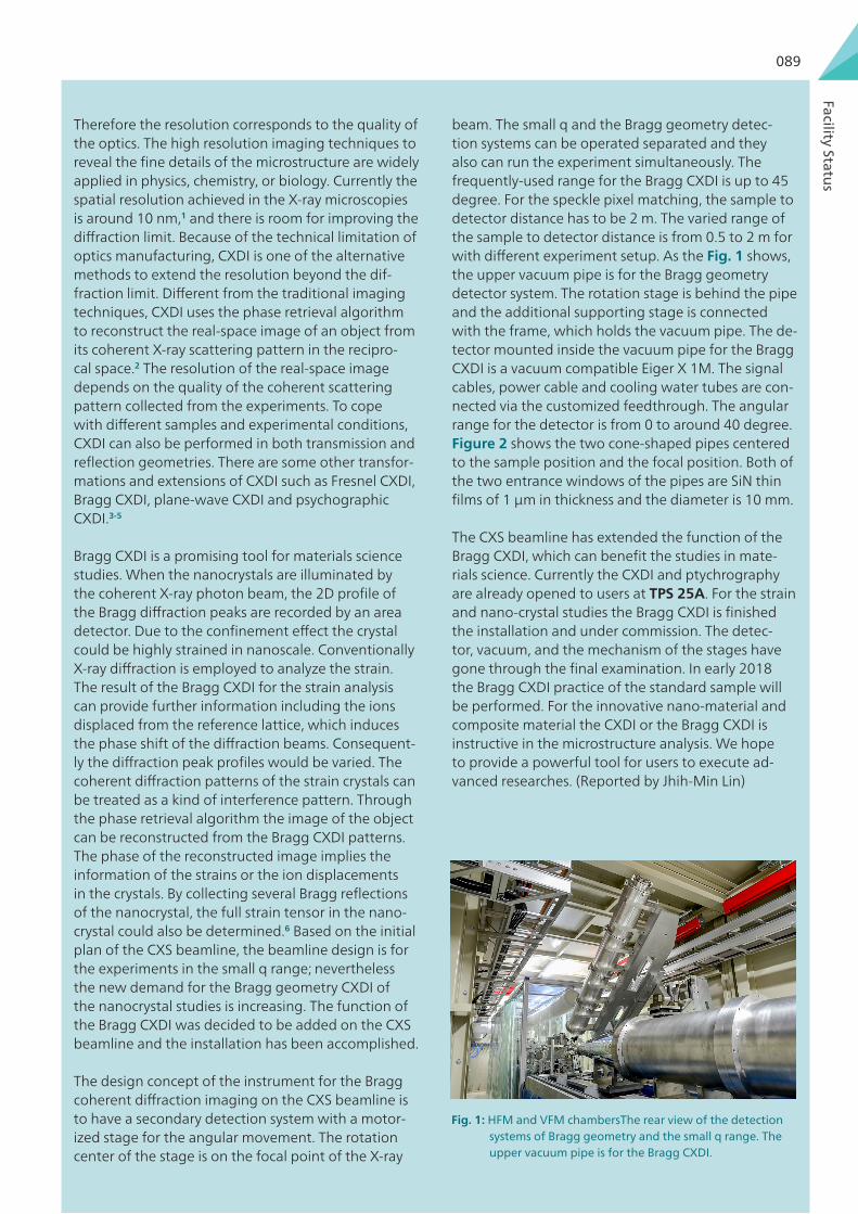
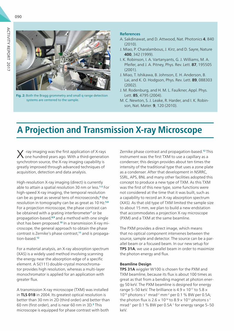
beam. The small q and the Bragg geometry detec-tion systems can be operated separated and they also can run the experiment simultaneously. The frequently-used range for the Bragg CXDI is up to 45 degree. For the speckle pixel matching, the sample to detector distance has to be 2 m. The varied range of the sample to detector distance is from 0.5 to 2 m for with different experiment setup. As the Fig. 1 shows, the upper vacuum pipe is for the Bragg geometry detector system. The rotation stage is behind the pipe and the additional supporting stage is connected with the frame, which holds the vacuum pipe. The de-tector mounted inside the vacuum pipe for the Bragg CXDI is a vacuum compatible Eiger X 1M. The signal cables, power cable and cooling water tubes are con-nected via the customized feedthrough. The angular range for the detector is from 0 to around 40 degree. Figure 2 shows the two cone-shaped pipes centered to the sample position and the focal position. Both of the two entrance windows of the pipes are SiN thin films of 1 µm in thickness and the diameter is 10 mm.
The CXS beamline has extended the function of the Bragg CXDI, which can benefit the studies in mate-rials science. Currently the CXDI and ptychrography are already opened to users at TPS 25A. For the strain and nano-crystal studies the Bragg CXDI is finished the installation and under commission. The detec-tor, vacuum, and the mechanism of the stages have gone through the final examination. In early 2018 the Bragg CXDI practice of the standard sample will be performed. For the innovative nano-material and composite material the CXDI or the Bragg CXDI is instructive in the microstructure analysis. We hope to provide a powerful tool for users to execute ad-vanced researches. (Reported by Jhih-Min Lin)
Fig. 1: HFM and VFM chambersThe rear view of the detection systems of Bragg geometry and the small q range. The upper vacuum pipe is for the Bragg CXDI.
Facility Status
ACTIV
ITY REPO
RT 2017
090
References A. Sakdinawat, and D. Attwood, Nat. Photonics 4, 840
(2010).J. Miao, P. Charalambous, J. Kirz, and D. Sayre, Nature
400, 342 (1999).I. K. Robinson, I. A. Vartanyants, G. J. Williams, M. A.
Pfeifer, and J. A. Pitney, Phys. Rev. Lett. 87, 195505 (2001).
J. Miao, T. Ishikawa, B. Johnson, E. H. Anderson, B. Lai, and K. O. Hodgson, Phys. Rev. Lett. 89, 088303 (2002).
J. M. Rodenburg, and H. M. L. Faulkner, Appl. Phys. Lett. 85, 4795 (2004).
M. C. Newton, S. J. Leake, R. Harder, and I. K. Robin-son, Nat. Mater. 9, 120 (2010).
Fig. 2: Both the Bragg grommetry and small q range detection systems are centered to the sample.
A Projection and Transmission X-ray Microscope
X -ray imaging was the first application of X-rays one hundred years ago. With a third-generation
synchrotron source, the X-ray imaging capability is greatly improved through advanced techniques of acquisition, detection and data analysis.
High-resolution X-ray imaging (direct) is currently able to attain a spatial resolution 30 nm or less.1-3 For high-speed X-ray imaging, the temporal resolution can be as great as several tens of microseconds;4 the resolution in tomography can be as great as 10 Hz.5,6 For a projection microscope, the phase contrast can be obtained with a grating interferometer7 or be propagation-based,8,9 and a method with one single shot has been proposed.10 In a transmission X-ray mi-croscope, the general approach to obtain the phase contrast is Zernike’s phase contrast,11 and is propaga-tion-based.12
For a material analysis, an X-ray absorption spectrum (XAS) is a widely used method involving scanning the energy near the absorption edge of a specific element. A Si(111) double-crystal monochroma-tor provides high resolution, whereas a multi-layer monochromator is applied for an application with greater flux.
A transmission X-ray microscope (TXM) was installed in TLS 01B in 2004. Its greatest optical resolution is better than 30 nm in 2D (third order) and better than 60 nm (first order), and is near 60 nm in 3D.2 This microscope is equipped for phase contrast with both
Zernike phase contrast and propagation-based.12 This instrument was the first TXM to use a capillary as a condenser; this design provides about ten times the intensity of the traditional type that uses a zone plate as a condenser. After that development in NSRRC, SSRL, APS, BNL and many other facilities adopted this concept to produce a new type of TXM. As this TXM was the first of this new type, some functions were not considered at the time that it was built, such as a capability to record an X-ray absorption spectrum (XAS). As that old type of TXM limited the sample size to about 15 mm, we plan to build a new endstation that accommodates a projection X-ray microscope (PXM) and a TXM at the same beamline.
The PXM provides a direct image, which means that no optical component intervenes between the source, sample and detector. The source can be a par-allel beam or a focused beam. In our new setup for TPS 31A, we use a parallel beam in order to maximize the photon energy and flux.
Beamline Design TPS 31A wiggler W100 is chosen for the PXM and TXM beamline, because its flux is about 100 times as great as that from a bending magnet at photon ener-gy 50 keV. The PXM beamline is designed for energy range 5–50 keV. The brilliance is 4.9 × 10¹⁷ to 5.8 × 10¹⁶ photons s-1 mrad-2 mm-2 per 0.1 % BW per 0.5A; the photon flux is 2.6 × 10¹⁴ to 8.9 × 10¹² photons s-1 mrad-1 per 0.1 % BW per 0.5A-1 for energy range 5–50 keV.


![A BRAGG LINE - Piedmont Historical Society Bragg Line.pdf · A Bragg Line by Dan W. Olds [6 July 2014] Page 1 A BRAGG LINE The purpose of this report is to collect, organize and share](https://static.documents.pub/doc/80x56/5aca87517f8b9a6b578dbd0d/a-bragg-line-piedmont-historical-bragg-linepdfa-bragg-line-by-dan-w-olds-6.jpg)


