111
The Study on Sulfur-Vanadium Pentoxide Composites as Cathode Materials for Magnesium Secondary Battery by Masashi INAMOTO Graduate School of Saitama Institute of Technology 2016
The Study on
Sulfur-Vanadium Pentoxide Composites as
Cathode Materials
for Magnesium Secondary Battery
by
Masashi INAMOTO
Graduate School of Saitama Institute of Technology
2016
PREFACE
Nowadays, secondary batteries that have high capacity and are intrinsically safe are
required due to the significant progress of electronic devices, especially portable devices
such as mobile phones, tablets and power sources for electric vehicles. The study on
magnesium secondary batteries is still in the early stages. There are some impediments
to the practical use of such devices: slower diffusion and intercalation of Mg2+
into
cathode materials.
This is the thesis for a doctorate of Saitama Institute of Technology and relates to a
vanadium pentoxide (V2O5) and sulfur composite as a magnesium secondary battery
cathode, with the aim of developing a cathode material that would allow the repeated
insertion/extraction of Mg2+
ions and would exhibit high capacity.
In Chapter 2 of the thesis, a V2O5 and sulfur composite synthesized by carbon
felt-assisted microwave plasma of water (CF-MWP) that is symbolized as S-V2O5
showed a capacity of 300 mAh/g. It was found that the S-V2O5 particles were composed
of two parts; an inner core of rigid V2O5 crystals covered by an approximately 10 nm
thick surface layer similar to a V2O5 xerogel and incorporating sulfur. X-ray
photoelectron spectroscopic analysis of the S-V2O5 electrode surface after charge and
discharge indicated the presence of an electrolyte layer, representing a so-called solid
electrolyte interphase (SEI), formed at the interface between the electrolyte and the
S-V2O5 electrode surface. This SEI plays an important role in promoting the solid-state
diffusion of Mg2+
ions. In Chapter 3, it was found the S-V2O5 achieved the higher
capacity when combined with a metal oxide. The highest recorded capacity (420
mAh/g) was obtained upon the addition of manganese(II) oxide (MnO2) to form the
composite SMn-V2O5. Structural assessments showed that the bulk of the SMn-V2O5
had an orthorhombic V2O5 structure, while the surface was composed of xerogel-like
V2O5 and a solid solution of MnO2 and sulfur. In Chapter 4, the author summarized
work to prepare a V2O5 xerogel by microwave irradiation and the results of structural
and electrochemical properties assessments. X-ray diffraction showed that the V2O5
xerogel prepared by microwave irradiation had a low degree of crystallinity, while
charge-discharge tests revealed a specific capacity of 463 mAh/g. In Chapter 5, the
preparation of a S-V2O5 gel using a new process and subsequent evaluation of the
structure and electrode performance is discussed. Structural analysis showed that the
bulk S-V2O5 gel adopted a V2O5 xerogel-like structure with a surface layer
incorporating the sulfur and in a stable planar orientation, and that the surface had a
reformed hard amorphous structure due to the CF-MWP treatment. Charge-discharge
tests determined a specific capacity of 450 mAh/g, and cyclic voltammetry found
almost perfect stability after the second cycle.
Through these Chapters, the S-V2O5 composite can be expected to function as a
cathode material via Mg2+
ion insertion/extraction based on its enhanced cycling ability
and structural stability. This study did not undertake a detailed analysis of the sulfur
states in the S-V2O5, although such states are believed to have a significant effect on ion
insertion/extraction. In future work, the effect of sulfur states on Mg2+
ion
insertion/extraction should be assessed. I believe the results herein demonstrate the
feasibility of using magnesium secondary batteries for practical applications based on
further advances in the anode and electrolyte.
February 2016
Masashi Inamoto
ACKNOWLEDGEMENT
I wish to express my deepest gratitude to Professor Tatsuhiko Yajima of Saitama
Institute of Technology for supervising and supporting this study. I would also like to
thank Professor Uchiyama Shunichi, Professor Osamu Niwa, Professor Yasushi Hasebe
and Associate Professor Hiroaki Matsuura for taking the time to review this thesis.
I also wish to sincerely thank Dr. Hideki Kurihara for his instruction in
electrochemistry and microwave theory and for providing the opportunity to perform
this study. Thanks are also extended to Mr. Teruyasu Mutaguchi of the Comprehensive
Open Innovation Center of Saitama University (formerly the President of the Saitama
Industrial Technology Center) and Mr. Yasuyuki Suzuki of the Saitama Industrial
Technology Center for their assistance in entering the doctoral course and for providing
guidance and encouragement. I am indebted to members of the Yajima Laboratory and
to related people of the Saitama Industrial Technology Center for their support and
advice during my research. Lastly, special thanks are due to my wife Sachiko Inamoto
for giving me moral support.
February 2016
Masashi Inamoto
LIST OF PUBLICATIONS
1. M. Inamoto, H. Kurihara, T. Yajima, Electrode Performance of S-doped Vanadium
Pentoxide as Cathode Active Material for Rechargeable Magnesium Battery,
Journal of the Surface Finishing Society of Japan, 62 (10), 516-520 (2011), In
Japanese.
2. M. Inamoto, H. Kurihara, T. Yajima, Electrode Performance of Vanadium Pentoxide
Xerogel Prepared by Microwave Irradiation as Active Cathode Material for
Rechargeable Magnesium batteries, Electrochemistry, 80 (6), 421-422 (2012).
3. M. Inamoto, H. Kurihara, T. Yajima, Vanadium pentoxide-based composite
synthesized using microwave water plasma for cathode material in rechargeable
magnesium batteries, Materials, 6 (10), 4514-4522 (2013).
4. M. Inamoto, H. Kurihara, T. Yajima, Electrode Performance of Sulfur-Doped
Vanadium Pentoxide Gel Prepared by Microwave Irradiation for Rechargeable
Magnesium Batteries, Current Physical Chemistry, 4 (3), 238-243 (2014).
- 1 -
CONTENTS
Chapter 1
General Introduction
1.1 Battery Introduction 6
1.2 Lithium Secondary Batteries 8
1.3 Magnesium Secondary Batteries 11
1.3.1 Cathode materials 14
1.4 Plasma Theory 17
1.4.1 Atmospheric Pressure Discharge Plasma 17
1.4.2 Atmosphere Pressure Discharge Plasma Using Carbon Felt 20
1.4.3 Carbon-felt Microwave Water Plasma (CF-MWP) 22
1.5 Background of this study 24
1.6 Purpose and significance of this research 26
1.7 Reference 28
Chapter 2
Electrode Performance of Sulfur-Vanadium Pentoxide Composite Cathode
Materials
2.1 Introduction 32
2.2 Experimental 34
2.2.1 Synthesis of sulfur-vanadium pentoxide composite (S-V2O5) 34
2.2.2 Electrochemical characteristics 36
2.2.3 Electrochemical behavior of the S-V2O5 electrode surface 37
- 2 -
2.3 Results and discussion 38
2.3.1 Electrochemical characteristics 38
2.3.2 Structural analysis 40
2.3.3 Electrochemical characteristic of S-V2O5 electrode 49
2.3.4 Electrochemical behavior of the S-V2O5 electrode surface 52
2.4 Conclusions 57
2.5 References 58
Chapter 3
Electrode Performance of Vanadium Pentoxide-based Composite Cathode
Materials
3.1 Introduction 62
3.2 Experimental 63
3.2.1 Preparation of cathode material by CF-MWP 63
3.2.2 Electrochemical characteristics 64
3.2.3 Structural analysis 65
3.3 Results and discussion 66
3.3.1 Electrochemical characteristics 66
3.3.2 Structural analysis 68
3.4 Conclusions 73
3.5 References 74
- 3 -
Chapter 4
Electrode Performance of Vanadium Pentoxide Xerogel Prepared by Microwave
Irradiation as an Active Cathode Material
4.1 Introduction 76
4.2 Experimental 77
4.3 Results and discussion 79
4.4 Conclusions 85
4.5 References 86
Chapter 5
Electrode Performance of Sulfur-Doped Vanadium Pentoxide Gel Composite
Cathode Materials
5.1 Introduction 88
5.2 Experimental 90
5.2.1 Preparation method for sulfur-containing V2O5 gel 90
5.2.2 Electrochemical analysis 92
5.3 Results and discussion 93
5.3.1 Structural analysis 93
5.3.2 Electrochemical analysis 98
5.4 Conclusions 102
5.5 References 103

- 4 -
Chapter 6
General Conclusions 104
- 5 -
Chapter 1
General Introduction
1.1 Battery Introduction
1.2 Lithium Secondary Batteries
1.3 Magnesium Secondary Batteries
1.3.1 Cathode materials
1.4 Plasma Theory
1.4.1 Atmospheric Pressure Discharge Plasma
1.4.2 Atmosphere Pressure Discharge Plasma Using Carbon Felt
1.4.3 Carbon-felt Microwave Water Plasma (CF-MWP)
1.5 Background of this study
1.6 Purpose and significance of this research
1.7 Reference
- 6 -
1.1 Battery Introduction
There are two main types of batteries in everyday usage; primary and secondary (or
rechargeable). Primary batteries are capable of one time use only and so are used until
they are depleted and then disposed of. The most common primary batteries are alkaline
manganese and zinc-air. In contrast, secondary batteries are constructed in a manner that
allows for the original electrode materials to be restored by applying an external voltage.
The first-generation secondary batteries, which are still in use, were lead-acid. More
modern secondary batteries are the nickel-cadmium, nickel-metal hydride and
lithium-ion types.
Circa 1980, secondary batteries appeared that incorporated so-called aqueous
electrolytes, such as the nickel-cadmium and nickel-metal hydride batteries. Aqueous
batteries such as these generate an electromotive force less than 1.5 V because of the
electrolysis of water, and their applications are limited based on their size and weight.
However, the demand for small rechargeable batteries has increased in association with
the development and diffusion of portable electronic devices such as mobile phones.
The lithium-ion battery, the first nonaqueous electrolyte device, was subsequently
developed by Yoshino et al.1)
in the late 1980s, and the Sony Corporation put
lithium-ion batteries into commercial use in the early 1990s.2)
Lithium-ion batteries are
now widely used in many practical applications.3)
In fact, these are now the standard
battery technology and have been optimized to a large extent. Recently, the use of
lithium-ion batteries as power sources for hybrid and electric vehicles has grown rapidly
as a means of reducing fossil fuel dependence.
As the smallest monovalent ion apart from H+, lithium is an ideal ionic guest for
- 7 -
transferring electronic charges into various insertion hosts. However, there are only a
limited number of countries that produce lithium (such as Chile, China and Argentina)
and the element is often found in inaccessible locations, such as in concentrations of
0.04-1.16% in brine ponds, thus requiring almost a year for the final production of
lithium carbonate. Notwithstanding this low accessibility, rechargeable lithium batteries
will, for the time being, play a pivotal role as the most advanced electrochemical power
sources.4)
In the meantime, many research institutions are developing non-lithium
battery systems, such as sodium-ion, magnesium-ion and metal-air batteries, in order to
ensure a sustainable supply of electrochemical energy storage devices.
- 8 -
1.2 Lithium Secondary Batteries
Even though the emphasis of this report is on magnesium batteries, the general
workings of a lithium-ion battery will first be given, because this introduction serves as
a good basis for the understanding of rechargeable ion transfer batteries. The main
elements of a battery are the cathode, anode and electrolyte. In most modern batteries, a
porous membrane is also present between the cathode and the anode to eliminate the
possibility of electronic short-circuits, to minimize electrolyte usage and to increase the
structural integrity of the device. The cathode and anode are the positive and negative
electrodes, respectively, meaning that, upon discharge, electrons and cations flow from
the anode to the cathode. Lithium secondary batteries have received significant attention
because of their higher energy densities compared to Ni-Cd, Ni-metal hydride (MH) and
Ni-H2 batteries.
- 9 -
Cathode Materials
A lithium-ion battery employs so-called intercalation cathodes based on crystalline
materials in which lithium is one of the major constituents. The key characteristics that
are important for cathode materials are high ionic conductivity, favorable volume
expansion upon discharge, high energy density and the ability to accommodate the extra
charge and tension left in the structure when lithium ions are removed. The chemical
equation summarizing the charge reaction at the cathode is as follows.
LiMO(s) → Li+(sol) + MO(s) + e- (1.1)
MO: metal oxide
Some typical cathode materials are presented in Table 1.1.
- 10 -
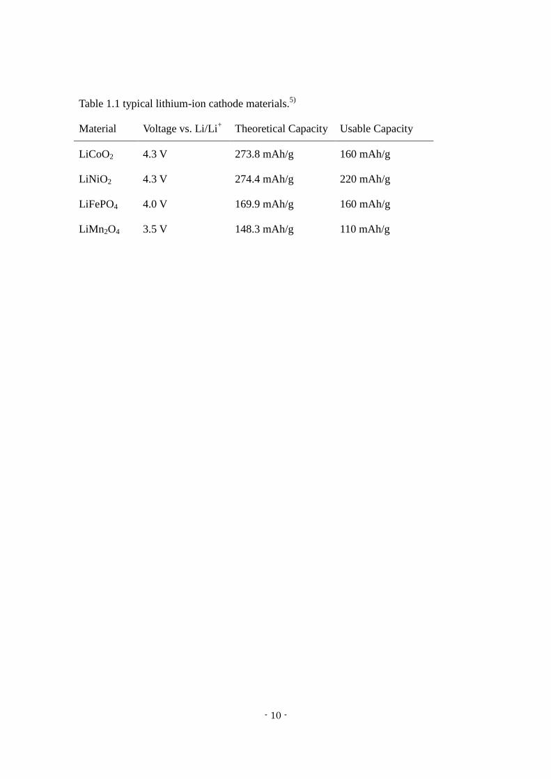
Table 1.1 typical lithium-ion cathode materials.5)
Material Voltage vs. Li/Li+ Theoretical Capacity Usable Capacity
LiCoO2 4.3 V 273.8 mAh/g 160 mAh/g
LiNiO2 4.3 V 274.4 mAh/g 220 mAh/g
LiFePO4 4.0 V 169.9 mAh/g 160 mAh/g
LiMn2O4 3.5 V 148.3 mAh/g 110 mAh/g
- 11 -
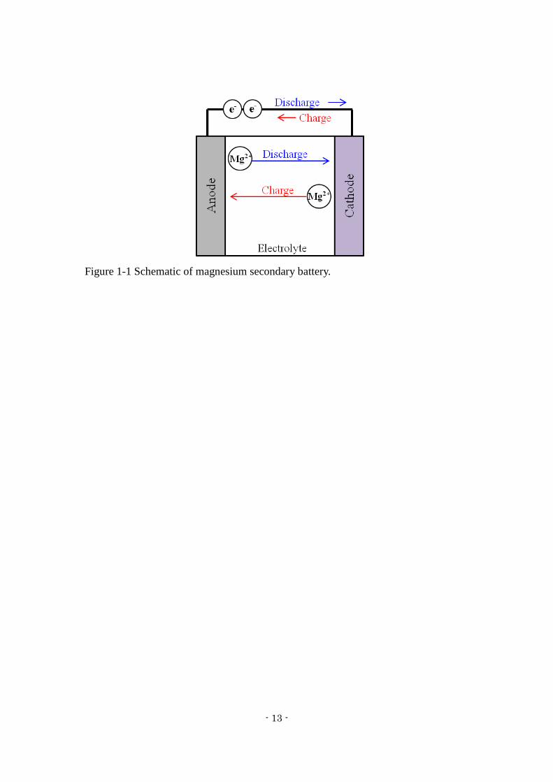
1.3 Magnesium Secondary Batteries
Figure 1-1 summarizes the operating principles of a magnesium secondary battery.
Magnesium offers benefits as a battery constituent because it is divalent, i.e., the Mg2+
ion carries twice the charge of a Li ion.
Magnesium secondary batteries are a promising candidate to meet the future
electrical energy storage needs of large-scale mobile and stationary devices, due to their
advantages in terms of low cost as well as the high environmental abundance of
magnesium metal and the divalent character of the Mg2+
ion. Among the possible
alternatives to lithium-ion devices, magnesium secondary batteries have been much
researched over the last two decades and magnesium is thought to represent the best
metal anode material for high energy density batteries. The standard electrode potential
of magnesium is -2.367 V. Although the theoretical gravimetric charge density of
magnesium is lower than that of pure lithium (2233 mAh/g for Mg vs. 3884 mAh/g for
Li), the divalent nature of magnesium ions presents a potential advantage in terms of
volumetric capacity (3833 mAh/cm3 for Mg vs. 2046 mAh/cm
3 for Li). Thus, while
magnesium batteries might be heavier, they will be smaller. Despite its potential
reactivity, magnesium is suitably stable in ambient air so as to allow handling and
electrode preparation processes. Magnesium is also relatively benign and is the fifth
most abundant element in the earth’s crust; at present, 700,000 tons of magnesium are
produced per year.
Despite these positive attributes, the development of magnesium ion technology has
not kept pace with that of lithium ion technology. One critical issue impeding progress
has been the development of a suitable electrolyte to enable the reversible release of
- 12 -
Mg2+
ions from a magnesium metal anode.6)
Unlike the Li+ ion conducting surface films
formed by polar aprotic electrolyte solutions on Li metal electrodes, the surface films
formed on magnesium metal often block the transport of Mg2+
ions. A second ongoing
challenge is the development of cathode materials with high reversible capacity and
adequate operating voltage under appropriate power output conditions. Due to the high
valency of Mg2+
ions, the kinetics of solid state diffusion through inorganic cathode
materials are slow, resulting in low reversible capacity and reduced power output.7)
Significant progress has been made since Aurbach et al.8)
first reported a magnesium
secondary battery prototype.4),9)
This has included new electrolytes10)
and recent
advances in cathode materials.11),12)
These advancements have led to the study of
magnesium secondary batteries all over the world.
- 13 -
Figure 1-1 Schematic of magnesium secondary battery.
- 14 -
1.3.1 Cathode materials
With the recent increase in reports involving cathode materials for rechargeable
magnesium batteries, it is important to assess the research in order to obtain new
concepts for future study. Specifically, there have been many Mg2+
ion studies involving
numerous cathode compositions and various phases. The choice of cathode materials for
magnesium secondary batteries is extremely limited because divalent Mg2+
insertion/extraction in a host compound is difficult, presumably due to the stronger ionic
interaction and differing charge redistribution of magnesium compared to the lithium
ion.13)
Various cathode materials have been reported, however, including molybdenum
sulfide (Mo3S4), vanadium pentoxide (V2O5), manganese oxide (MnO2) and sulfur.
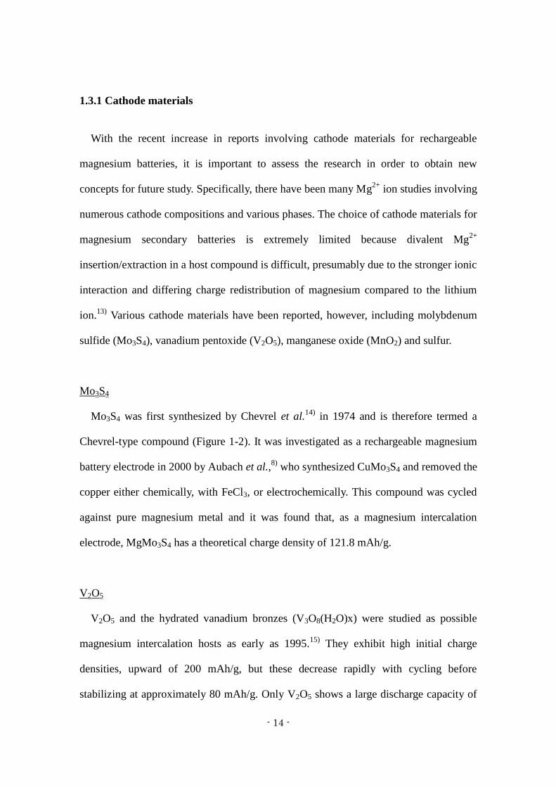
Mo3S4
Mo3S4 was first synthesized by Chevrel et al.14)
in 1974 and is therefore termed a
Chevrel-type compound (Figure 1-2). It was investigated as a rechargeable magnesium
battery electrode in 2000 by Aubach et al.,8)
who synthesized CuMo3S4 and removed the
copper either chemically, with FeCl3, or electrochemically. This compound was cycled
against pure magnesium metal and it was found that, as a magnesium intercalation
electrode, MgMo3S4 has a theoretical charge density of 121.8 mAh/g.
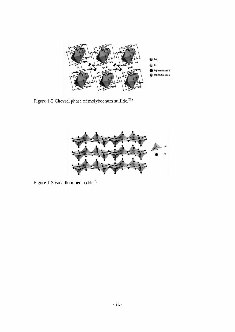
V2O5
V2O5 and the hydrated vanadium bronzes (V3O8(H2O)x) were studied as possible
magnesium intercalation hosts as early as 1995.15)
They exhibit high initial charge
densities, upward of 200 mAh/g, but these decrease rapidly with cycling before
stabilizing at approximately 80 mAh/g. Only V2O5 shows a large discharge capacity of

- 15 -
170 mAh/g, in an acetonitrile solution containing H2O.16)
MgXV2O5 prepared by a sol
gel method was shown to be quasi-reversible and had a delivered capacity above 250
mAh/g over several cycles.17)
Imamura et al. was able to fabricate a cathode in which
Mg2+
was inserted in a manner similar to the usual Li+ insertion.
18)
MnO2
Zhang et al. reported potassium-stabilized manganese dioxide as a candidate cathode
material.19)
The capacity of this cathode was 282 mAh/g on the initial discharge,
although this value quickly faded to 134 mAh/g on the second cycle and continued to
decrease with prolonged cycling. Spinel MnO2 has also been synthesized using a
microwave reactor20)
and the capacity of this material was found to be 80 mAh/g on the
first discharge.
Sulfur
Kim et al. demonstrated the crystallization of electrochemically active species from
the reaction between hexamethyldisilazide magnesium chloride and aluminum
trichloride as a means of synthesizing a non-nucleophilic electrolyte. They confirmed
that electrochemical conversion between sulfur and magnesium sulfide can be
successfully performed using this electrolyte.10)
- 16 -
Figure 1-2 Chevrel phase of molybdenum sulfide.21)
Figure 1-3 vanadium pentoxide.7)
- 17 -
1.4 Plasma Theory
1.4.1 Atmospheric Pressure Discharge Plasma
There are several methods of producing a plasma, but it is common to use
atmospheric pressure discharge. Atmospheric pressure discharge occurs when a certain
relationship holds true between two electrodes in a gas as a function of pressure and gap
length, termed Paschen's Law. This relationship is given below.
Vs = f (Pd) (1.2)
P: gas pressure [Torr]
d: gap length [m]
An atmospheric pressure discharge plasma is an industrially effective technology
because it requires no vacuum apparatus or exhaust system and is capable of high
throughput.
The discharge in this process is a sudden and momentary electric current that flows
between two objects at different electrical potentials. There are two types of discharge;
glow discharge and arc discharge. A glow discharge apparatus consists of two electrodes
in a cell held at low pressure, with an electrode potential of several hundred volts
applied between the two electrodes. A small population of atoms within the cell is
initially ionized and these ions are driven towards the cathode by the electric potential,
while electrons are driven towards the anode by the same potential. The initial
population of ions and electrons ionizes other atoms upon collision. As long as the
- 18 -
potential is maintained, a population of ions and electrons remains. The discharge
current in this apparatus is less than 1 A. In contrast, arc discharge achieves a
completely ionized state by thermal ionization. As the discharge current increases, the
gas temperature is raised and thermal ionization occurs. A discharge current is typically
more than 10 A.
Corona discharge is a continuous discharge that is caused by the unequal electric field
around a needle electrode. There are different types of corona, including a glow corona,
which regularly occurs in the region of the electrode, and a streamer corona, which
develops linearly and occurs intermittently and can inflict damage on electrodes. Corona
discharge is unsuitable for gaseous processing, since it is generated in a linear space.
Finally, barrier discharge devices consist of two electrodes with a dielectric layer set
between the two electrodes. Barrier discharge is generated by the application of an
alternating voltage. In this device, the dielectric layer prevents damage to the electrodes
by streamer coronas.
A plasma is a state in which electrons and cations coexist while maintaining micro
electrical neutrality, and is often referred to as the fourth state of matter. A plasma is
usually generated by applying energy to compounds in the vapor state, and combustion,
discharge, nuclear radiation and laser beams are used as energy sources for plasma
generation. Discharge is the most commonly used energy source. A glow discharge
plasma is a non-equilibrium plasma; the electron temperature is several eV, the electron
density ranges from 109 to 10
11 cm
-3, the ion temperature is several 0.1 eV and the gas
temperature is several 0.01 eV. An arc plasma, however, is a thermal plasma; the
electron temperature is several eV, the electron density ranges from 1015
to 1017
cm-3
and the ion and gas temperature are several eV, corresponding to 1000 °C. Therefore,

- 19 -
the apparatus for treatment using an arc plasma is difficult to manufacture.
Atmospheric pressure plasmas are used in a variety of materials processing
techniques.22)
Atmospheric pressure plasma devices can provide a crucial advantage
over low pressure plasmas because they eliminate complications introduced by the need
for vacuum. This technique therefore has a number of applications, such as high
temperature materials processing and ozone production for water purification.
- 20 -
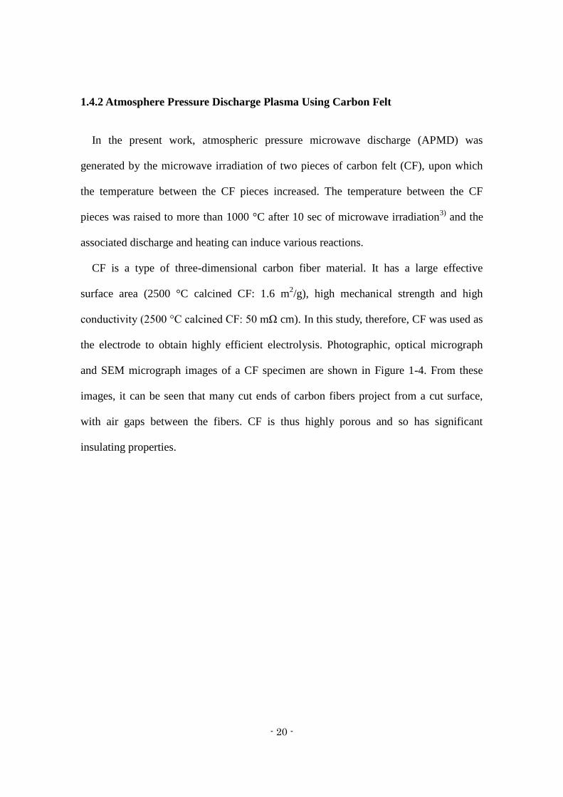
1.4.2 Atmosphere Pressure Discharge Plasma Using Carbon Felt
In the present work, atmospheric pressure microwave discharge (APMD) was
generated by the microwave irradiation of two pieces of carbon felt (CF), upon which
the temperature between the CF pieces increased. The temperature between the CF
pieces was raised to more than 1000 °C after 10 sec of microwave irradiation3)
and the
associated discharge and heating can induce various reactions.
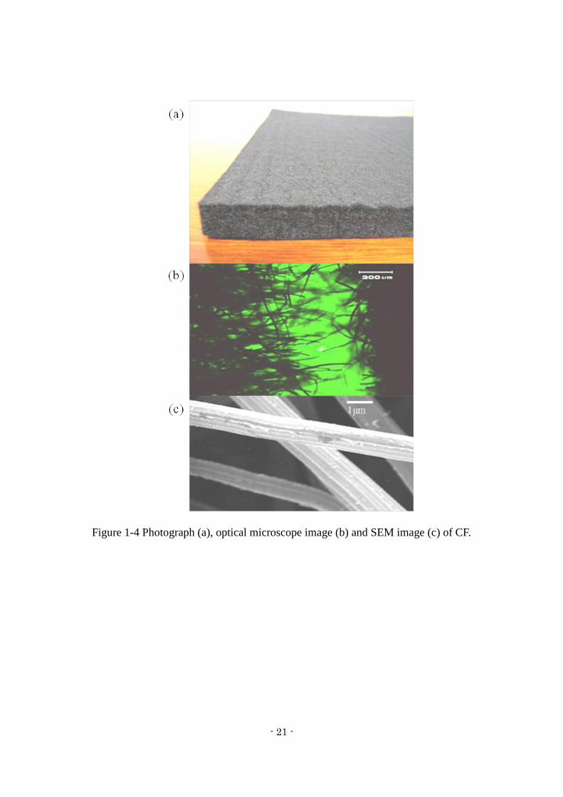
CF is a type of three-dimensional carbon fiber material. It has a large effective
surface area (2500 °C calcined CF: 1.6 m2/g), high mechanical strength and high
conductivity (2500 °C calcined CF: 50 mΩ cm). In this study, therefore, CF was used as
the electrode to obtain highly efficient electrolysis. Photographic, optical micrograph
and SEM micrograph images of a CF specimen are shown in Figure 1-4. From these
images, it can be seen that many cut ends of carbon fibers project from a cut surface,
with air gaps between the fibers. CF is thus highly porous and so has significant
insulating properties.
- 21 -
Figure 1-4 Photograph (a), optical microscope image (b) and SEM image (c) of CF.
- 22 -
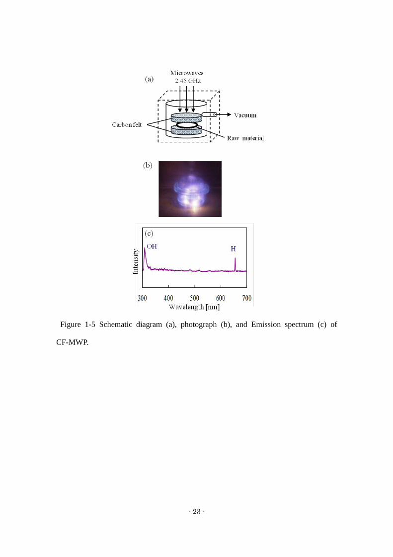
1.4.3 Carbon-felt Microwave Water Plasma (CF-MWP)
As noted, this work employed an atmospheric pressure discharge plasma using carbon
felt as a means of easily generating a plasma under reduced pressure. A schematic of the
carbon-felt microwave water plasma (CF-MWP) device is provided in Figure 1-5a. This
apparatus is constructed by first wetting a quantity of the raw material to be processed,
after which it is placed between two pieces of CF. The resulting construction is placed
in a glass vessel that can be placed under vacuum. The raw material in the vessel is
subsequently irradiated with 2.45 GHz microwaves under reduced pressure and a water
plasma is formed in response to the electric discharge between the two CF pieces
(Figures 1-5b, 5c). The water plasma uniformly treats the raw material because water is
homogeneously distributed throughout the material. Another characteristic of CF-MWP
is that the temperature rise is very rapid and arrives at a thermal equilibrium state.
Because of these characteristics, CF-MWP synthesis proceeds via inhibited oxidation
and/or reduction of the raw material.
- 23 -
Figure 1-5 Schematic diagram (a), photograph (b), and Emission spectrum (c) of
CF-MWP.
- 24 -
1.5 Background of this study
At present, secondary batteries that have high capacity and are intrinsically safe are
required due to the significant progress of electronic devices, especially portable devices
such as mobile phones and tablets, and as power source for electric vehicles.
Magnesium secondary, lithium-sulfur and lithium-air batteries are all being developed
as next-generation devices to satisfy these requirements. Of these, the magnesium
secondary battery is the most promising based on the anticipated safety advantage.
At the moment, the study of magnesium secondary batteries is in the early stages.
There are two main impediments to the practical use of such devices: (1) slower
diffusion and intercalation of Mg2+
into cathode materials and (2) incompatibility
between anodes and electrolytes due to the high polarizability of Mg2+
. Therefore, it is
essential to design an adequate cathode and compatible anode and electrolyte.24)
Cathode materials for magnesium secondary battery candidates are limited to those
employed in the lithium-ion batteries, and include Mo3S4, MnO2 and V2O5 as described
above. Levi et al. has suggested three main strategies to improve the kinetics of Mg
transport in relevant cathode materials, using nanoscale materials, hydrates or similar
intercalation compounds or cluster-containing compounds that readily attain local
electroneutrality.11)
A combination of the first and second strategies in a material, such
as a V2O5 gel and its derivatives, can generate relatively high voltage and capacity, but
the associated kinetics are insufficient for practical battery use because of the
incomplete charge screening upon cation insertion. Nevertheless, the development of
cathode materials using V2O5 has been studied for some time, and has even been
considered with regard to lithium secondary batteries.25)
For this reason, the present
work also focuses on V2O5.
- 25 -
Crystalline V2O5 consists of layers of V2O5-based polyhedra and this structure
provides pathways for ion insertion and extraction. The insertion of Mg2+
into V2O5 is a
slow process, possibly due to the concurrent chemical modification of the V2O5 crystal
surface. In recent studies, various groups have investigated hydrated V2O5 xerogels26)
and aerogels27)
in which water molecules are bound between the layers of V2O5. It is
reported that a V2O5 xerogel exhibits a high capacity.28)
However, some of the water
molecules in this gel remain bound to the magnesium and are extracted from the lattice
during charging, ultimately leading to structural failure of the crystal upon cycling and a
diminished capacity after the first cycle.
- 26 -
1.6 Purpose and significance of this research
Layered V2O5 represents a stable structure and Mg2+
ions inserted into V2O5 layers
are not readily extracted because of the chemical interactions between the Mg2+
ions
and the V2O5 oxygen. Sulfur is known to have a high theoretical capacity (1672 mAh/g)
but also has an unstable crystalline structure that may dissolve in the electrolyte upon
extraction of Mg2+
ions from the sulfur. V2O5 with added sulfur has been studied as a
cathode material for lithium batteries because of the unique charge-discharge properties
of this material.29)
However, the addition of sulfur requires a highly precise and well
controlled synthesis.29)
In the work reported herein, an attempt was made to apply sulfur-vanadium pentoxide
prepared by CF-MWP as a cathode material for used in magnesium secondary batteries.
The goal was to develop a unique cathode material allowing the insertion/extraction of
magnesium ions and exhibiting high capacity.
This thesis is presented in two parts. The first part (Chapters 2 to 3) explains the
crystal core structure of a proposed V2O5 cathode, while the second part (Chapters 4 and
5) focuses on the design of a V2O5 cathode with a xerogel core structure. Chapter 1
serves as a general introduction and Chapter 6 presents conclusions.
Chapter 1 describes the characteristic of plasma-based synthesis and the possibilities
suggested by previous studies of magnesium secondary batteries and V2O5 cathodes.
Chapter 2 (Electrode Performance of Sulfur-Vanadium Pentoxide Composite Cathode
Materials) discusses the treatment of V2O5 and sulfur using CF-MWP to inhibit the
reduction of V2O5 and the oxidation of sulfur, generating S-V2O5. The structure of
S-V2O5 and the electrochemical characteristics of a S-V2O5 electrode are described.
In Chapter 3 (Electrode Performance of Vanadium Pentoxide-based Composite
- 27 -
Cathode Materials), the synthesis of V2O5 with sulfur and metal oxides (MnO2, Mo2O3,
Fe2O3, ZrO2, NiO) using CF-MWP is detailed.
Chapter 4 (Electrode Performance of Vanadium Pentoxide Xerogel Prepared by
Microwave Irradiation as an Active Cathode Material) involves the desorption of
structural water from a V2O5 xerogel using microwave irradiation. The electrode
performance of a V2O5 xerogel formed by microwave irradiation is discussed based on
structural and electrochemical analyses.
In Chapter 5 (Electrode Performance of Sulfur-Doped Vanadium Pentoxide Gel
Composite Cathode Materials), investigations of the electrochemical performance and
structure of a S-V2O5 gel prepared by CF-MWP after mixing of a V2O5 xerogel and
sulfur are detailed.
Chapter 6 presents conclusions and a general overview of study results and future
prospects.
- 28 -
1.7 Reference for Chapter 1
1) A. Yoshino, K. Sanechika and T. Nakajima, US4668595 A (1987)
2) Y. Nishi, H. Azuma and A. Omaru, US4959281 A (1990)
3) S. Okamoto, T. Ichitsubo, T. Kawaguchi, Y. Kumagai, F. Oba, S. Yagi, K. Shimokawa,
N. Goto, T. Doi and E. Matsubara, Advanced Science, 2 (8), 1-9 (2015)
4) H. D. Yoo, I. Shterenberg, Y. Gofer, G. Gershinsky, N. Pour and D. Aurbach, Energy
& Environmental Science, 6 (8), 2265-2279 (2013)
5) M. Yoshio, R.J. Brodd and A. Kozawa, editors. Lithium-ion batteries Science and
Technologies (2009)
6) P. Novák, R. Imhof and O. Haas, Electrochim. Acta, 45 (1-2), 351-367 (1999)
7) M. M. Huie, D. C. Bock, E. S. Takeuchi, A. C. Marschilok and K. J. Takeuchi, Coord.
Chem. Rev., 287, 15-27 (2015)
8) D. Aurbach, Z. Lu, A. Schechter, Y. Gofer, H. Gizbar, R. Turgeman, Y. Cohen, M.
Moshkovich and E. Levi, Nature, 407 (6805), 724-727 (2000)
9) D. Aurbach, G. S. Suresh, E. Levi, A. Mitelman, O. Mizrahi, O. Chusid and M.
Brunelli, Adv. Mater., 19 (23), 4260-4267 (2007)
10) H. S. Kim, T. S. Arthur, G. D. Allred, J. Zajicek, J. G. Newman, A. E. Rodnyansky,
A. G. Oliver, W. C. Boggess and J. Muldoon, Nat Commun, 2, 427 (2011)
11) E. Levi, Y. Gofer and D. Aurbach, Chem. Mater., 22 (3), 860-868 (2010)
12) E. Lancry, E. Levi, Y. Gofer, M. D. Levi and D. Aurbach, J. Solid State
Electrochem., 9 (5), 259-266 (2005)
13) J. Muldoon, C. B. Bucur, A. G. Oliver, T. Sugimoto, M. Matsui, H. S. Kim, G. D.
Allred, J. Zajicek and Y. Kotani, Energy & Environmental Science, 5 (3), 5941-5950
- 29 -
(2012)
14) R. Chevrel, M. Sergent and J. Prigent, Mater. Res. Bull., 9 (11), 1487-1498 (1974)
15) P. Novák, W. Scheifele, F. Joho and O. Haas, J. Electrochem. Soc., 142 (8),
2544-2550 (1995)
16) P. Novák and J. Desilvestro, J. Electrochem. Soc., 140 (1), 140-144 (1993)
17) S. H. Lee, R. A. DiLeo, A. C. Marschilok, K. J. Takeuchi and E. S. Takeuchi, ECS
Electrochemistry Letters, 3 (8), A87-A90 (2014)
18) D. Imamura and M. Miyayama, Solid State Ionics, 161 (1-2), 173-180 (2003)
19) R. Zhang, X. Yu, K.-W. Nam, C. Ling, T. S. Arthur, W. Song, A. M. Knapp, S. N.
Ehrlich, X.-Q. Yang and M. Matsui, Electrochem. Commun., 23, 110-113 (2012)
20) H. Kurihara, T. Yajima and S. Suzuki, Chem. Lett., 37 (3), 376-377 (2008)
21) E. Levi, E. Lancry, A. Mitelman, D. Aurbach, O. Isnard and D. Djurado, Chem.
Mater., 18 (16), 3705-3714 (2006)
22) A. Schutze, J. Y. Jeong, S. E. Babayan, J. Park, G. S. Selwyn and R. F. Hicks,
Plasma Science, IEEE Transactions on, 26 (6), 1685-1694 (1998)
23) H. Kurihara, Saitama Institute of Technology, Ph.D., (2008)
24) Y. Liu, L. Jiao, Q. Wu, J. Du, Y. Zhao, Y. Si, Y. Wang and H. Yuan, Journal of
Materials Chemistry A, 1 (19), 5822-5826 (2013)
25) Y. Li, J. Yao, E. Uchaker, M. Zhang, J. Tian, X. Liu and G. Cao, The Journal of
Physical Chemistry C, 117 (45), 23507-23514 (2013)
26) C.-Y. Lee, A. C. Marschilok, A. Subramanian, K. J. Takeuchi and E. S. Takeuchi,
PCCP, 13 (40), 18047-18054 (2011)
27) D. B. Le, S. Passerini, F. Coustier, J. Guo, T. Soderstrom, B. B. Owens and W. H.
Smyrl, Chem. Mater., 10 (3), 682-684 (1998)

- 30 -
28) D. Imamura, M. Miyayama, M. Hibino and T. Kudo, J. Electrochem. Soc., 150 (6),
A753-A758 (2003)
29) V. Gorchkov, P. Novák and O. Volkov, US6916579 B2 (2005)
- 31 -
Chapter 2
Electrode Performance of Sulfur-Vanadium Pentoxide Composite Cathode
Materials
2.1 Introduction
2.2 Experimental
2.2.1 Synthesis of sulfur-vanadium pentoxide composite (S-V2O5)
2.2.2 Electrochemical characteristics
2.2.3 Electrochemical behavior of the S-V2O5 electrode surface
2.3 Results and discussion
2.3.1 Electrochemical characteristics
2.3.2 Structural analysis
2.3.3 Electrochemical characteristic of S-V2O5 electrode
2.3.4 Electrochemical behavior of the S-V2O5 electrode surface
2.4 Conclusions
2.5 References
- 32 -
2.1 Introduction
High-density secondary batteries are expected to be used as power sources for
electrical vehicles. Divalent cation secondary batteries are promising because they can
produce twice the current per atom of lithium batteries and have a higher energy density.
The beryllium ion, which has the largest theoretical capacity of divalent cations, is not a
good secondary battery cathode material because it forms covalent bonds. On the other
hand, the magnesium ion, which has the second largest theoretical capacity of divalent
cations, is expected to be applied for secondary battery cathode materials because of its
higher tendency to undergo ionic bonding compared with covalent bonding. Therefore,
magnesium secondary batteries, which have a long history of research, have begun to
draw attention for next-generation power storage applications. Magnesium is
inexpensive, safe to handle, environmentally friendly, and naturally abundant.1)
However, Mg2+
ions form strong electrostatic interactions with anions, undergo slow
diffusion into cathode materials, and are easily trapped at the cathode. In addition, the
crystal structure of cathode materials deteriorates or the electrolyte degrades during
cycles of insertion/desorption of Mg2+
ions on/from the cathode at high voltage. For
these reasons, magnesium secondary batteries do not have a high capacity or a long
cycle life.2-6)
Therefore, the commercial viability of magnesium secondary batteries requires
cathode materials that are stable for the insertion/desorption of Mg2+
ions. There have
been a limited number of materials available as cathodes for magnesium secondary
batteries: metal oxides7-11)
and sulfides12-13)
have mainly been reported as cathode
materials. Metal oxides have stable crystalline structures but easily trap Mg2+
ions. On
- 33 -
the other hand, metal sulfides do not easily trap Mg2+
ions; however, they tend to have
unstable crystalline structures that could possibly dissolve in the electrolyte.
Therefore, we have investigated ways to resolve such problems by changing the
crystalline structure of the surface through the addition of sulfur to a metal oxide. The
conduction properties of sulfur, which are low, could be improved by mixing it with
metal oxide and carrying out a heat treatment. Metal oxide such as vanadium pentoxide
(V2O5) with added sulfur has been previously examined as a cathode material for
lithium secondary batteries because it has promising charge-discharge depth
properties.14)
However, the addition of sulfur requires high-precision control of the
synthesis conditions.14)
In this chapter, we discuss the application of V2O5 with added
sulfur (S-V2O5), prepared by the carbon-felt microwave water plasma (CF-MWP)
technique, as a cathode material.15,16)
The electrode performance and structural analysis
of S-V2O5, and the electrochemical behavior of the S-V2O5 electrode surface are
reported.
- 34 -
2.2 Experimental
2.2.1 Synthesis of sulfur-vanadium pentoxide composite (S-V2O5)
V2O5 and sulfur were mixed in a molar ratio of 3:1 in a ball mill (P-6, Fritsch Co.,
Ltd.) under an air atmosphere. The composite was wetted down and then treated with
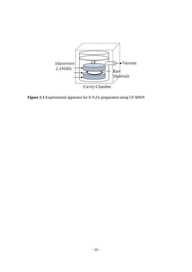
CF-MWP. Figure 2-1 shows the experimental setup for the CF-MWP process.
Specifically, 2.0 g of each raw material was placed between pieces of carbon felt (30
mm diameter) and a 500 W, 2.45 GHz microwave was used to irradiate the material
under reduced pressure (0.001 MPa) for 2 min to synthesize S-V2O5. The structure and
the binding state of S-V2O5 were measured using X-ray diffraction (XRD; RINT 2000,
Rigaku Corp.), X-ray photoelectron spectroscopy (XPS; ESCA Quantum 2000,
Ulvac-Phi, Inc.), Fourier transform infrared spectroscopy with an attached diffuse
reflection system (DRS-FTIR; IRPrestige-21, DRS-8000A, Shimadzu Corp.), Raman
spectroscopy (XploRA, Horiba, Ltd.), and transmission electron microscopy (TEM;
HF2000, Hitachi High-Technologies Corp.).
- 35 -
Figure 2-1 Experimental apparatus for S-V2O5 preparation using CF-MWP.
- 36 -
2.2.2 Electrochemical characteristics
The electrode performance was evaluated using three-electrode cells. The electrodes
were prepared from a mixture of the cathode material, acetylene black, and a
polyvinylidene fluoride binder with N-methyl-2-pyrrolidone with a weight ratio of
10:3:1. The resulting slurry was spread on carbon paper. The electrode was dried at
110 °C for 1.5 h. S-V2O5 was charged with magnesium ions and used as a counter
electrode. A magnesium ribbon was used as the reference electrode. This electrode
showed the same potential changes as a magnesium alloy plate. Namely, the S-V2O5
was had Mg2+
insertion at 30 mAh/g at 0.7 V versus Mg/Mg2+
. For the electrolyte
solution, 0.3 M Mg(ClO4)2 and 1.8 M H2O dissolved in propylene carbonate (PC) was
used. Charge-discharge tests were conducted at a constant current of 60 mA/g (0.2 C).
All trials were conducted at 20 °C.
- 37 -
2.2.3 Electrochemical behavior of the S-V2O5 electrode surface
Depth profiles of the electrode surface and chemical-bonding state after the first
charge-discharge cycle were analyzed using X-ray photoelectron spectroscopy (XPS;
ESCA Quantum 2000, Ulvac-Phi, Inc.). The discharged sample was prepared by
discharging to 0.9 V, and the charged sample was prepared by discharging to 0.9 V and
then charging to 2.4 V. For the electrolyte solution, 0.3 M Mg(ClO4)2 and 1.8 M H2O
dissolved in propylene carbonate was used. A magnesium ribbon was used as the
reference electrode, and S-V2O5 was charged with magnesium ions and used as a
counter electrode. XPS analysis was conducted using Ar+ ions, an accelerating voltage
of 4 kV, a pass energy of 23.50 eV, and a step size of 0.050 eV. All procedures from
removal of the electrode from the cell to placement in the XPS spectrometer were
conducted under a nitrogen atmosphere. All measurements were performed at room
temperature (25 °C).
- 38 -
2.3 Results and discussion
2.3.1 Charge-discharge characteristics
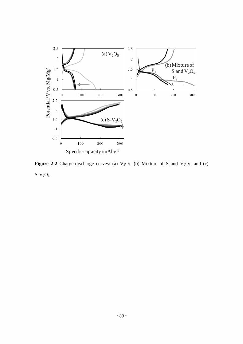
The charge-discharge test results are shown in Figure 2-2 for V2O5, mixed V2O5 and
sulfur, and S-V2O5. The capacity of the V2O5 electrode was 160 mAh g-1
at the first
cycle but decreased to 70 mAh g-1
from the second cycle. This result corresponds with a
previous report.14)
The discharge curve for the composite mixture of V2O5 and sulfur
showed two plateaus at 1.4 V (P1) and 1.0 V (P2) vs. Mg/Mg2+
, which are attributed to
V2O5 and sulfur, respectively. The P2 plateau was observed only at the first discharge,
and was not evident from the second discharge, which indicates that the sulfur is
dissolved in the electrolyte when Mg2+
is extracted from the electrode during the first
charge. The curve for S-V2O5 did not show a plateau but decreased linearly from 1.6 V
to 1.0 V, in contrast to the composite mixture of V2O5 and sulfur. S-V2O5 has a high
capacity (300 mAh g-1
) and good cycleability, which indicates that the surface of
S-V2O5 is amorphous. The bulk of S-V2O5 has a V2O5 crystalline structure and the
change in the S-V2O5 surface occurs not only due to the CF-MWP process, as discussed
later. Therefore, these results indicate a reduction in the cycle degradation because the
dissolution of sulfur is inhibited.
- 39 -
Figure 2-2 Charge-discharge curves: (a) V2O5, (b) Mixture of S and V2O5, and (c)
S-V2O5.
Po
ten
tial
/ V
vs.
Mg/M
g2
+
(a) V2O5
(b) Mixture of
S and V2O5P1
P2
(c) S-V2O5
Specific capacity /mAhg-1
- 40 -
2.3.2 Structural analysis
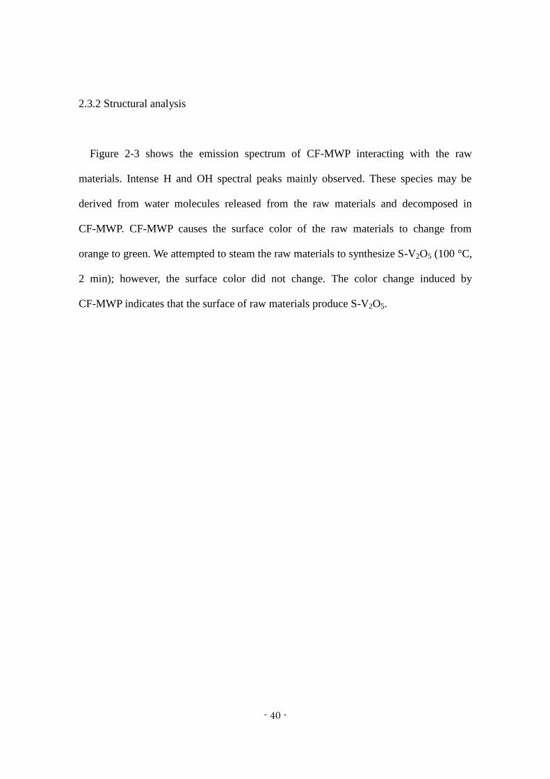
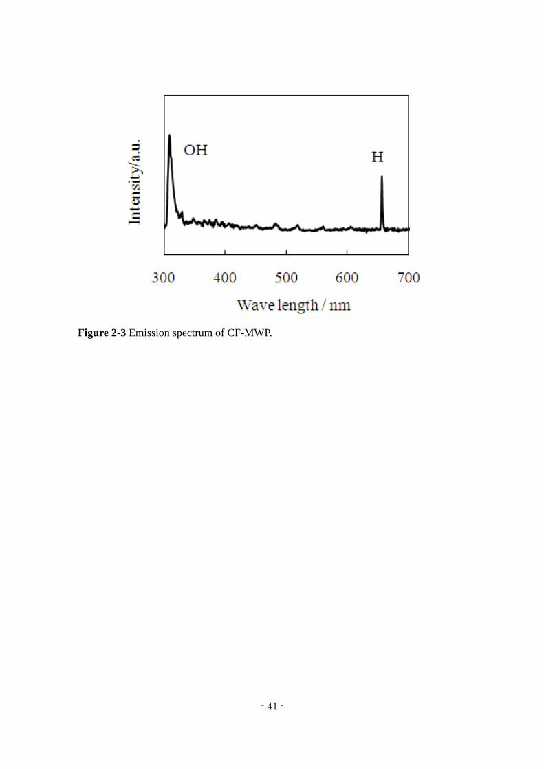
Figure 2-3 shows the emission spectrum of CF-MWP interacting with the raw
materials. Intense H and OH spectral peaks mainly observed. These species may be
derived from water molecules released from the raw materials and decomposed in
CF-MWP. CF-MWP causes the surface color of the raw materials to change from
orange to green. We attempted to steam the raw materials to synthesize S-V2O5 (100 °C,
2 min); however, the surface color did not change. The color change induced by
CF-MWP indicates that the surface of raw materials produce S-V2O5.
- 41 -
Figure 2-3 Emission spectrum of CF-MWP.
- 42 -
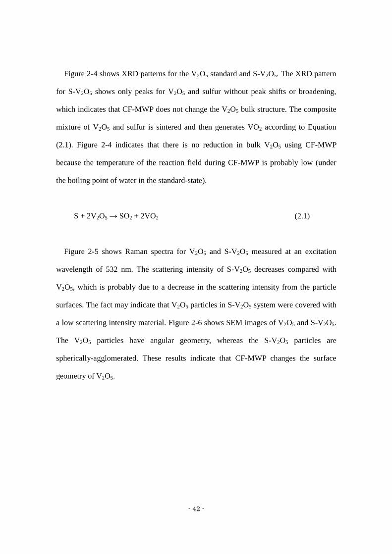
Figure 2-4 shows XRD patterns for the V2O5 standard and S-V2O5. The XRD pattern
for S-V2O5 shows only peaks for V2O5 and sulfur without peak shifts or broadening,
which indicates that CF-MWP does not change the V2O5 bulk structure. The composite
mixture of V2O5 and sulfur is sintered and then generates VO2 according to Equation
(2.1). Figure 2-4 indicates that there is no reduction in bulk V2O5 using CF-MWP
because the temperature of the reaction field during CF-MWP is probably low (under
the boiling point of water in the standard-state).
S + 2V2O5 → SO2 + 2VO2 (2.1)
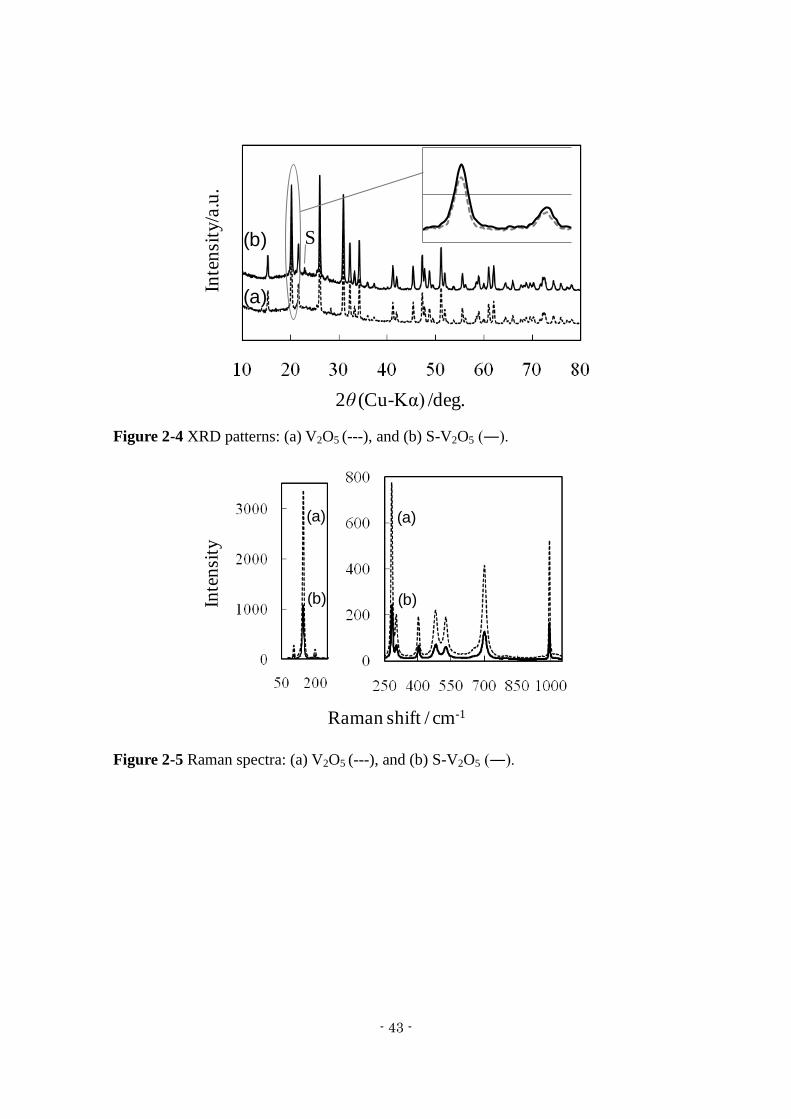
Figure 2-5 shows Raman spectra for V2O5 and S-V2O5 measured at an excitation
wavelength of 532 nm. The scattering intensity of S-V2O5 decreases compared with
V2O5, which is probably due to a decrease in the scattering intensity from the particle
surfaces. The fact may indicate that V2O5 particles in S-V2O5 system were covered with
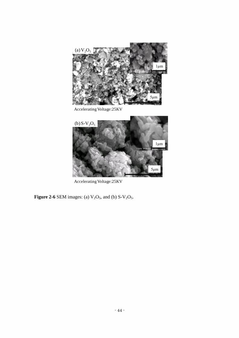
a low scattering intensity material. Figure 2-6 shows SEM images of V2O5 and S-V2O5.
The V2O5 particles have angular geometry, whereas the S-V2O5 particles are
spherically-agglomerated. These results indicate that CF-MWP changes the surface
geometry of V2O5.
- 43 -
Figure 2-4 XRD patterns: (a) V2O5 (---), and (b) S-V2O5 (―).
Figure 2-5 Raman spectra: (a) V2O5 (---), and (b) S-V2O5 (―).
Inte
nsi
ty/a
.u.
2θ (Cu-Kα) /deg.
S(b)
(a)
Raman shift / cm-1
Inte
nsi
ty
(b)
(a)
(b)
(a)
- 44 -
Figure 2-6 SEM images: (a) V2O5, and (b) S-V2O5.
(a) V2O5
(b) S-V2O5
Accelerating Voltage:25KV
5μm
1μm
Accelerating Voltage:25KV
5μm
1μm
- 45 -
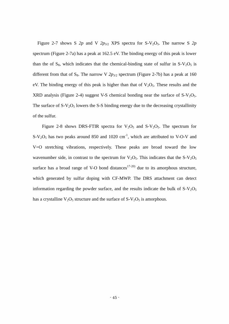
Figure 2-7 shows S 2p and V 2p3/2 XPS spectra for S-V2O5. The narrow S 2p
spectrum (Figure 2-7a) has a peak at 162.5 eV. The binding energy of this peak is lower
than the of S8, which indicates that the chemical-binding state of sulfur in S-V2O5 is
different from that of S8. The narrow V 2p3/2 spectrum (Figure 2-7b) has a peak at 160
eV. The binding energy of this peak is higher than that of V2O5. These results and the
XRD analysis (Figure 2-4) suggest V-S chemical bonding near the surface of S-V2O5.
The surface of S-V2O5 lowers the S-S binding energy due to the decreasing crystallinity
of the sulfur.
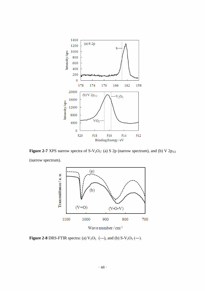
Figure 2-8 shows DRS-FTIR spectra for V2O5 and S-V2O5. The spectrum for
S-V2O5 has two peaks around 850 and 1020 cm-1
, which are attributed to V-O-V and
V=O stretching vibrations, respectively. These peaks are broad toward the low
wavenumber side, in contrast to the spectrum for V2O5. This indicates that the S-V2O5
surface has a broad range of V-O bond distances17-20)
due to its amorphous structure,
which generated by sulfur doping with CF-MWP. The DRS attachment can detect
information regarding the powder surface, and the results indicate the bulk of S-V2O5
has a crystalline V2O5 structure and the surface of S-V2O5 is amorphous.
- 46 -
Figure 2-7 XPS narrow spectra of S-V2O5: (a) S 2p (narrow spectrum), and (b) V 2p3/2
(narrow spectrum).
Figure 2-8 DRS-FTIR spectra: (a) V2O5 (---), and (b) S-V2O5 (―).
- 47 -
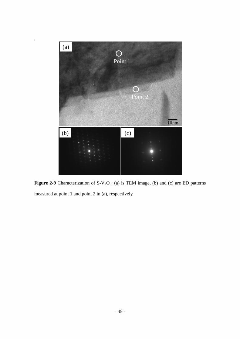
Figure 2-9 shows a TEM image and electron diffraction (ED) patterns of as-prepared
S-V2O5 at two different points in the sample. The surface of the sample is composed of
a thin 10-nm-thick layer (Figure 2-9a). The ED pattern of the S-V2O5 bulk indicates an
orthorhombic V2O5 structure (Figure 2-9b), while that of the thin surface layer had a
broader V-O band than that of orthorhombic V2O5 (Figure 2-9c).
V2O5 can easily absorb water from the atmosphere into the V2O5 layer, and this water
interferes with the insertion/extraction of Mg2+
ions. However, the S-V2O5 surface
accrues V-S bonds via the CF-MWP treatment, and the surface becomes amorphous
with a xerogel structure. Therefore, the high capacity and a good cycle life of S-V2O5
are due to the special structure consisting of a bulk of crystalline V2O5 and an
amorphous surface similar to V2O5 xerogel, which we call especially as the core-shell
structure. The characteristic core-shell structure may inhibit the dissolution of sulfur
into the electrolyte.
- 48 -
Figure 2-9 Characterization of S-V2O5; (a) is TEM image, (b) and (c) are ED patterns
measured at point 1 and point 2 in (a), respectively.
Point 2
Point 1
(a)
(b) (c)
10nm
- 49 -
2.3.3 Electrochemical characteristic of S-V2O5 electrode
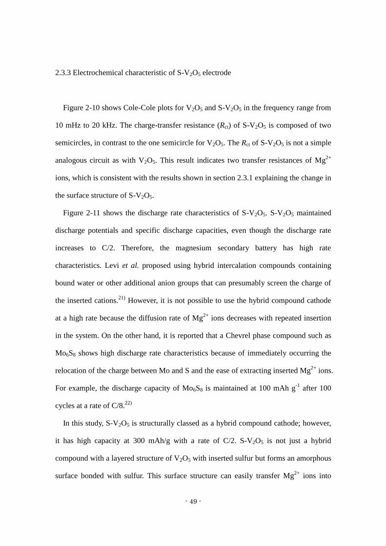
Figure 2-10 shows Cole-Cole plots for V2O5 and S-V2O5 in the frequency range from
10 mHz to 20 kHz. The charge-transfer resistance (Rct) of S-V2O5 is composed of two
semicircles, in contrast to the one semicircle for V2O5. The Rct of S-V2O5 is not a simple
analogous circuit as with V2O5. This result indicates two transfer resistances of Mg2+
ions, which is consistent with the results shown in section 2.3.1 explaining the change in
the surface structure of S-V2O5.
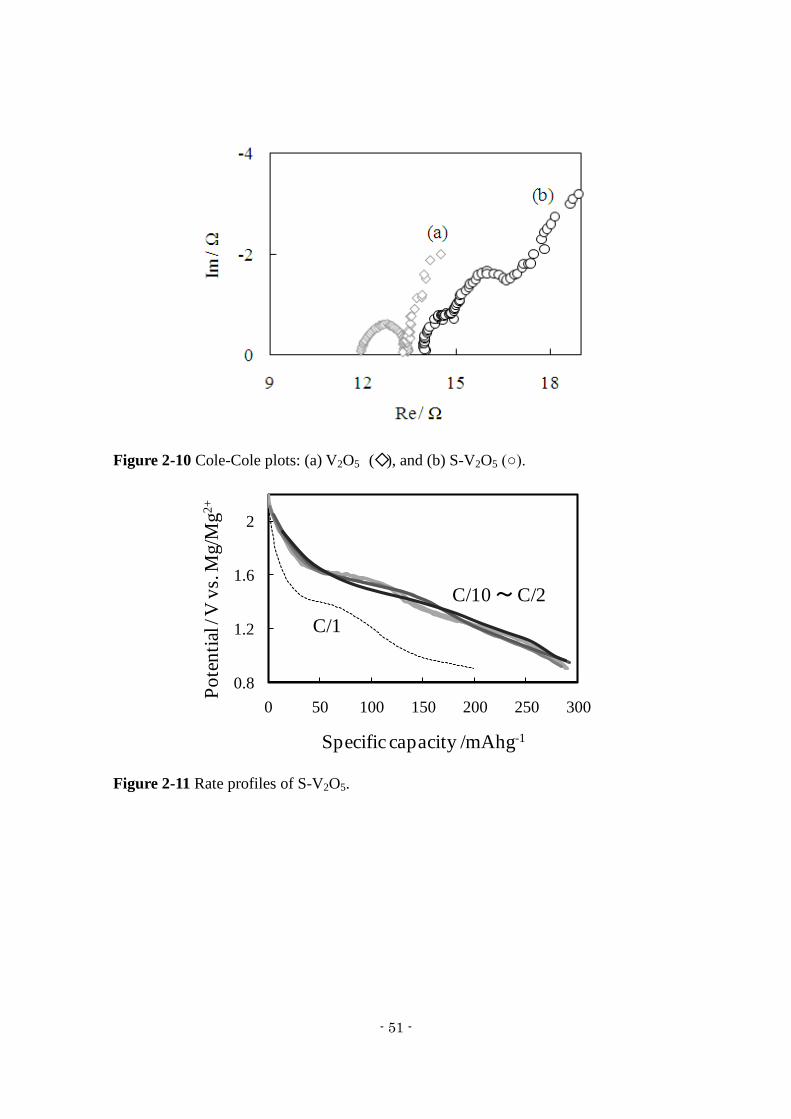
Figure 2-11 shows the discharge rate characteristics of S-V2O5. S-V2O5 maintained
discharge potentials and specific discharge capacities, even though the discharge rate
increases to C/2. Therefore, the magnesium secondary battery has high rate
characteristics. Levi et al. proposed using hybrid intercalation compounds containing
bound water or other additional anion groups that can presumably screen the charge of
the inserted cations.21)
However, it is not possible to use the hybrid compound cathode
at a high rate because the diffusion rate of Mg2+
ions decreases with repeated insertion
in the system. On the other hand, it is reported that a Chevrel phase compound such as
Mo6S8 shows high discharge rate characteristics because of immediately occurring the
relocation of the charge between Mo and S and the ease of extracting inserted Mg2+
ions.
For example, the discharge capacity of Mo6S8 is maintained at 100 mAh g-1
after 100
cycles at a rate of C/8.22)
In this study, S-V2O5 is structurally classed as a hybrid compound cathode; however,
it has high capacity at 300 mAh/g with a rate of C/2. S-V2O5 is not just a hybrid
compound with a layered structure of V2O5 with inserted sulfur but forms an amorphous
surface bonded with sulfur. This surface structure can easily transfer Mg2+
ions into

- 50 -
S-V2O5 because there is no passivated sulfur layer with low conductive properties but
instead charge transfer between V2O5 and sulfur can take place.
- 51 -
Figure 2-10 Cole-Cole plots: (a) V2O5 (◇), and (b) S-V2O5 (○).
Figure 2-11 Rate profiles of S-V2O5.
Specific capacity /mAhg-1
Po
ten
tial
/ V
vs.
Mg/M
g2
+
0.8
1.2
1.6
2
0 50 100 150 200 250 300
C/1
C/10 ~C/2
- 52 -
2.3.4 Electrochemical behavior of the S-V2O5 electrode surface
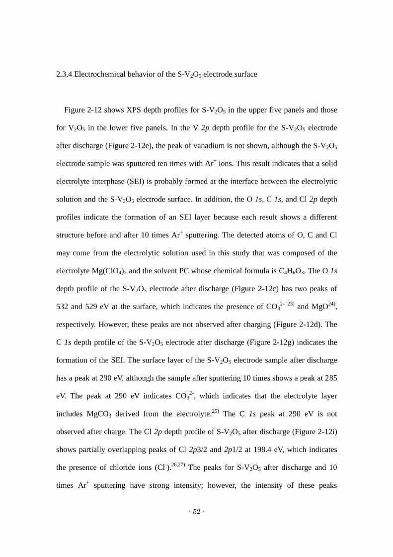
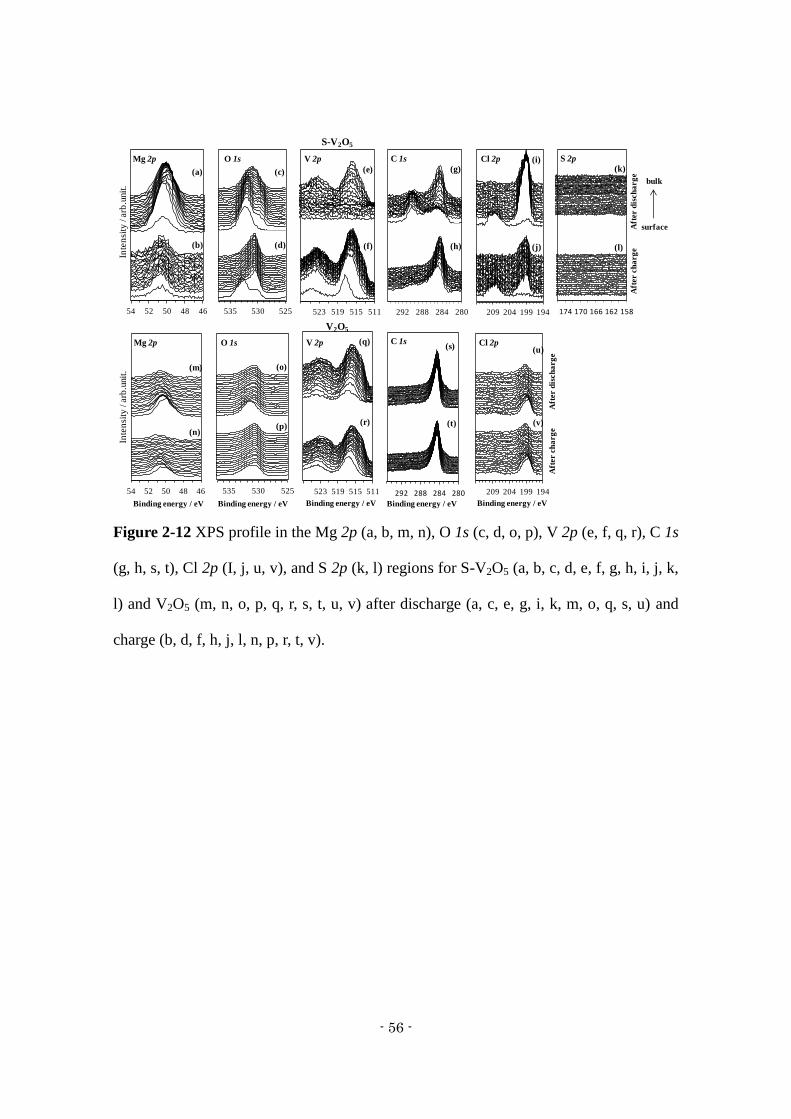
Figure 2-12 shows XPS depth profiles for S-V2O5 in the upper five panels and those
for V2O5 in the lower five panels. In the V 2p depth profile for the S-V2O5 electrode
after discharge (Figure 2-12e), the peak of vanadium is not shown, although the S-V2O5
electrode sample was sputtered ten times with Ar+ ions. This result indicates that a solid
electrolyte interphase (SEI) is probably formed at the interface between the electrolytic
solution and the S-V2O5 electrode surface. In addition, the O 1s, C 1s, and Cl 2p depth
profiles indicate the formation of an SEI layer because each result shows a different
structure before and after 10 times Ar+ sputtering. The detected atoms of O, C and Cl
may come from the electrolytic solution used in this study that was composed of the
electrolyte Mg(ClO4)2 and the solvent PC whose chemical formula is C4H6O3. The O 1s
depth profile of the S-V2O5 electrode after discharge (Figure 2-12c) has two peaks of
532 and 529 eV at the surface, which indicates the presence of CO32-
23)
and MgO24)
,
respectively. However, these peaks are not observed after charging (Figure 2-12d). The
C 1s depth profile of the S-V2O5 electrode after discharge (Figure 2-12g) indicates the
formation of the SEI. The surface layer of the S-V2O5 electrode sample after discharge
has a peak at 290 eV, although the sample after sputtering 10 times shows a peak at 285
eV. The peak at 290 eV indicates CO32-
, which indicates that the electrolyte layer
includes MgCO3 derived from the electrolyte.25)
The C 1s peak at 290 eV is not
observed after charge. The Cl 2p depth profile of S-V2O5 after discharge (Figure 2-12i)
shows partially overlapping peaks of Cl 2p3/2 and 2p1/2 at 198.4 eV, which indicates
the presence of chloride ions (Cl-).
26,27) The peaks for S-V2O5 after discharge and 10
times Ar+ sputtering have strong intensity; however, the intensity of these peaks
- 53 -
decreased after charging (Figure 2-12j), which indicates that the SEI layer incorporates
Cl- ions during the discharge process. The Mg 2p depth profile (Figure 2-12a) shows
high intensity and broad peaks at 50.2 eV, and MgCl2 (52.1 eV28)
) is not observed in the
electrolyte layer. These results demonstrate the formation of an SEI layer that is mainly
composed of MgCO3 and MgO and includes Cl- at the interface between the electrolyte
and the S-V2O5 surface after discharge. The S-V2O5 surface thus provides ease of Mg2+
insertion/extraction by the formation of the SEI layer.
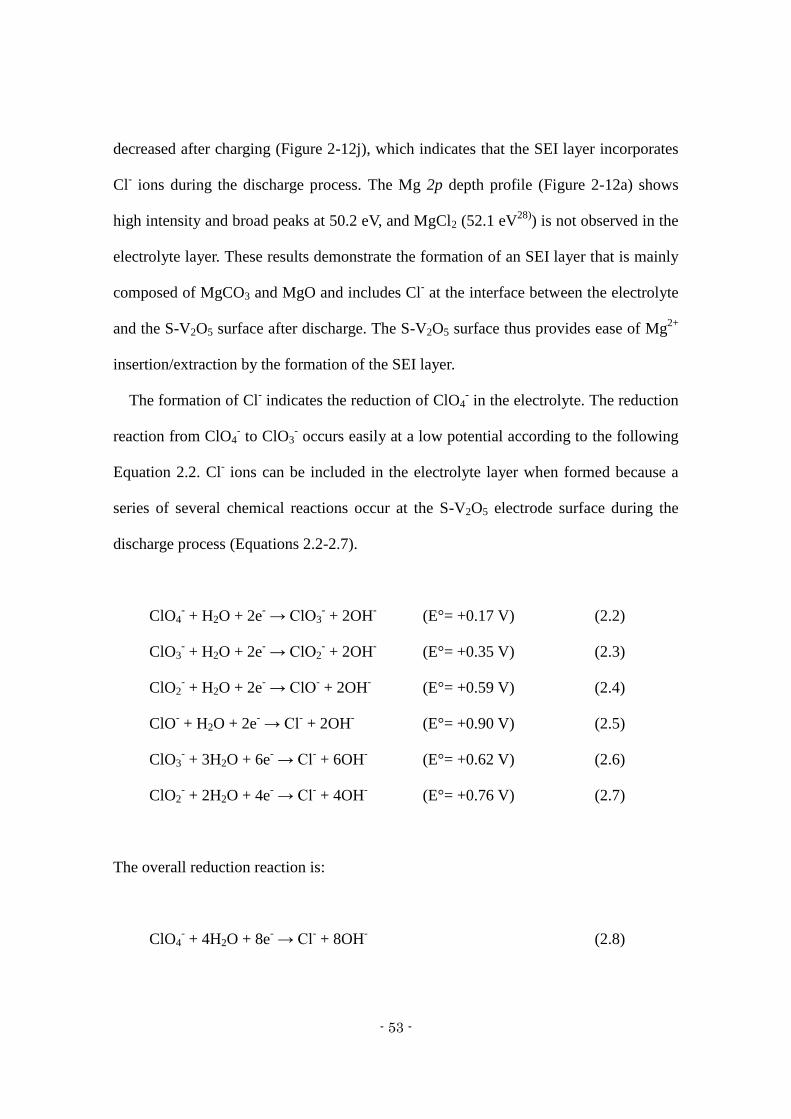
The formation of Cl- indicates the reduction of ClO4
- in the electrolyte. The reduction
reaction from ClO4- to ClO3
- occurs easily at a low potential according to the following
Equation 2.2. Cl- ions can be included in the electrolyte layer when formed because a
series of several chemical reactions occur at the S-V2O5 electrode surface during the
discharge process (Equations 2.2-2.7).
ClO4- + H2O + 2e
- → ClO3
- + 2OH
- (E°= +0.17 V) (2.2)
ClO3- + H2O + 2e
- → ClO2
- + 2OH
- (E°= +0.35 V) (2.3)
ClO2- + H2O + 2e
- → ClO
- + 2OH
- (E°= +0.59 V) (2.4)
ClO- + H2O + 2e
- → Cl
- + 2OH
- (E°= +0.90 V) (2.5)
ClO3- + 3H2O + 6e
- → Cl
- + 6OH
- (E°= +0.62 V) (2.6)
ClO2- + 2H2O + 4e
- → Cl
- + 4OH
- (E°= +0.76 V) (2.7)
The overall reduction reaction is:
ClO4- + 4H2O + 8e
- → Cl
- + 8OH
- (2.8)
- 54 -
Considering that Mg2+
transportation involves H2O molecules, the following scheme is
proposed:
ClO4- + [Mg(H2O)4]
2+ + 8e
- → Mg
2+ + Cl
- + 8OH
- (2.9)
The S 2p depth profiles shown in Figure 2-12(k, l) did not show the sulfur peak, and
the molar ratio of V:S in S-V2O5 was 100:7.824. Therefore, it is difficult to observe the
sulfur peak because the amount of sulfur involved in S-V2O5 was extremely small and
below the detection limit. It should be noted that sulfur probably sublimes during the
CF-MWP process. In addition, the raw material without added sulfur synthesized by
CF-MWP did not show a change in the surface structure. These results indicate that the
sulfur added to the raw material changes the surface structure of S-V2O5. Sulfur is
known in high capacity cathode materials.29)
However, the higher capacity of S-V2O5
than V2O5 is not due to the addition of sulfur but due to the change in the S-V2O5
surface structure to that similar to a V2O5 xerogel.
On the other hand, the Mg 2p XPS spectra of V2O5 after discharge (Figure 2-12m)
showed small peaks at 50.5 eV near the surface and 50.8 eV in the bulk. After charging
(Figure 2-12n), the peaks near the surface show a slight decrease in intensity. The O 1s
depth profile of V2O5 after discharge (Figure 2-12o) did not indicate MgCO3 (532 eV)
or MgO (529 eV), but the peak at 530.5 eV indicated the presence of V2O5 from the
surface to the bulk. This is different from that for the S-V2O5 electrode analysis. These
results indicate that the electrolyte layer formed at the S-V2O5 electrode surface is not
formed at the V2O5 electrode surface.

- 55 -
Each V 2p depth profile of S-V2O5 and V2O5 after discharge and charge (Figure 2-12e,
f, q, r) shows a wide spectrum of V 2p1/2 (523-524 eV) and V 2p3/2 (516-517 eV). The
wide spectrum indicates a mixture of different vanadium states: V5+
(V2O5, 517.6 eV),
V4+
(V2O4, 516.3 eV), and V3+
(V2O3, 515.7 eV). The V 2p3/2 spectrum for vanadium
metal shows a peak between 512.1 and 513.4 eV.30)
Therefore, it is difficult to recognize
the oxidation-reduction of vanadium due to Mg2+
insertion/extraction.
- 56 -
Figure 2-12 XPS profile in the Mg 2p (a, b, m, n), O 1s (c, d, o, p), V 2p (e, f, q, r), C 1s
(g, h, s, t), Cl 2p (I, j, u, v), and S 2p (k, l) regions for S-V2O5 (a, b, c, d, e, f, g, h, i, j, k,
l) and V2O5 (m, n, o, p, q, r, s, t, u, v) after discharge (a, c, e, g, i, k, m, o, q, s, u) and
charge (b, d, f, h, j, l, n, p, r, t, v).
158168
4648505254 525530535
(a)
(b) (d)
(c)
Mg 2p O 1s
S-V2O5
194199204209214
Cl 2pV 2p
(e)
(j)
(i)
bulk
surface
4648505254
(m)
(n)
525530535
(p)
(o)
Mg 2p O 1s
Inte
nsi
ty / a
rb.u
nit
.
Aft
er c
ha
rg
eA
fter d
isch
arg
e
511515519523527
Binding energy / eV
194199204209214
Binding energy / eV
Cl 2pV 2p (q)
(r)
Aft
er c
ha
rg
eA
fter d
isch
arg
e
511515519523527
V2O5
Binding energy / eV Binding energy / eV
(f)
280284288292
C 1s
(g)
(h)
C 1s
280284288292
Binding energy / eV
158162166170174
S 2p
(k)
(l)
(v)
(u)(s)
(t)
Inte
nsi
ty / a
rb.u
nit
.
- 57 -
2.4 Conclusion
Conclusions on the synthesis of S-V2O5 using CF-MWP and its electrode
characteristics are given in the following.
S-V2O5 has a characteristic structure which we call as the core-shell structure; a bulk
structure of crystalline V2O5 and an amorphous surface structure similar to V2O5
xerogel. A magnesium secondary battery with the S-V2O5 cathode has high capacity
(300 mAh/g) and increased cyclability. At a rate of C/2, the potential and specific
discharge capacity were not significantly degraded. Electrochemical analysis of the
discharge process indicated the presence of an SEI layer that is mainly composed of
MgCO3 and MgO, and includes Cl- ions, which is formed at interface between the
electrolyte and the S-V2O5 surface. The surface structure of S-V2O5 and the SEI layer
facilitate the Mg2+
insertion/extraction process at the S-V2O5 surface. However, the
sulfur added to the raw material did effect a significant change on the surface structure
of S-V2O5 during the CF-MWP process.
- 58 -
2.5 Reference of Chapter 2
1) H. D. Yoo, I. Shterenberg, Y. Gofer, G. Gershinsky, N. Pour and D. Aurbach,
Energy & Environmental Science, 6 (8), 2265-2279 (2013)
2) P. Novak, W. Scheifele and O. Haas, J. Power Sources, 54 (2), 479-482 (1995)
3) P. Novak and J. Desilvestro, J.Electrochem, Soc., 140 (1), 140-144 (1993)
4) D. Aurback, Z. Lu, A. Schemchter, Y. Goter, R. Tugeman, Y. Cohen, M.
Moshkovlch and E. Levl, Nature, 407 (6805), 724-727 (2000)
5) P. Novak, V. Shklover and R. Nesper, J. Phys. Chem., 185, 51-68 (1994)
6) P. Novak, W. Scheifele, F. Joho and O. Haas, J. Electrochem. Soc., 142 (8),
2544-2550 (1995)
7) L.Sanchez and J. P. Pereiraramos, J. Mater. Chem., 7 (3), 471-473 (1997)
8) Z. Feng, J. Yang, Y. NuLi and J. Wang, J. Power Sources, 184 (2), 604-607 (2008)
9) K. Makino, Y. Katayama, T. Miura and T. Kishi, J. Power Sources, 99 (1-2),
66-69 (2001)
10) N. Kumagai, S. Komaba, H. Sakai and N. Kumagai, J. Power Sources, 97-98,
515-517 (2001)
11) L. Yu and X. Zhang, Colloid Int. Sci., 278 (1), 160-165 (2004)
12) Z. L. Tao, L. N. Xu, X. L. Gou, J. Chen and H. T. Yuan, Chem. Commun., (18),
2080-2081 (2004)
13) A. Mitelman, M. D. Levi, E. Lancry, E. Levi and D. Aurbach, Chem. Commun.,
(41), 4212-4214 (2007)
14) V. Gorchkov, P. Novak and O. Volkov, US Patent 6916579 (2005)
15) H. Kurihara and T. yajima, Hyomen Gijutsu, 57 (12), 895-895 (2006)
- 59 -
16) H. Kurihara and T. yajima, Chem. Lett., 36 (4), 526-527 (2007)
17) M. Hibino, Y. Ikeda, Y. Noguchi, T. Kudo, Seisan Kenkyu, 52 (11), 516-522
(2000)
18) D. Imamura and M. Miyayama, Solid State Ionics, 161 (1-2), 173-180 (2003)
19) I. Stojkovića, N. Cvjetićanina, S. Markovićb, M. Mitrićc and S. Mentusa, Acta
Physica Pol. A, 117 (5), 837-840 (2010)
20) N. Koshiba, K. Takada, M. Nakanishi and Z. Takehara, Denki Kagaku, 62 (10),
332-338 (1994).
21) E. Levi, Y. Gofer, D. Aurbach, Chem. Mater., 22 (3), 860-868 (2010).
22) E. Lancry, E. Levi, Y. Gofer, M. Levi, D. Aurbach, J. Solid State Electrochem., 9
(5), 259-266 (2005).
23) S. Hwan Moon, T. Wook Heo, S. Young Park, J. Hyuk Kim and H. Joon Kim, J.
Electrochem. Soc., 154 (12), J408-J412 (2007)
24) O. Makita, S. Takagi and T. Gotoh, Shinku, 50 (3), 220-222 (2007)
25) K. Zhang, S. Wu, X. Wang, J. He, B. Sun, Y. Jia, T. Luo, F. Meng, Z. Jin, D. Lin,
W. Shen, L. Kong and J. Liu, J. Colloid Interface Sci., 446 (0), 194-202 (2015)
26) W. E. Morgan, J. R. Van Wazer and W. J. Stec, J. Am. Chem. Soc., 95 (3), 751-755
(1973)
27) J. P. Contour, A. Salesse, M. Froment, M. Garreau, J. Thevenin and D. Warin, J.
Microsc. Spectrosc. Electron, (4), 483-491 (1979)
28) S. Karakalos, A. Siokou and S. Ladas, Appl. Surf. Sci., 255 (21), 8941-8946
(2009)
29) H. Wang, Y. Yang, Y. Liang, J. T. Robinson, Y. Li, A. Jackson, Y. Cui and H. Dai,
Nano Letters, 11 (7), 2644-2647 (2011)

- 60 -
30) D. A. Shirley, R. L. Martin, S. P. Kowalczyk, F. R. MacFeely and L. Ley, Phys.
Rev. B, (15), 544-552 (1977)
- 61 -
Chapter 3
Electrode Performance of Vanadium Pentoxide-based Composite Cathode
Materials
3.1 Introduction
3.2 Experimental
3.2.1 Preparation of cathode material by CF-MWP
3.2.2 Electrochemical characteristics
3.2.3 Structural analysis
3.3 Results and discussion
3.3.1 Electrochemical characteristics
3.3.2 Structural analysis
3.4 Conclusions
3.5 References
- 62 -
3.1 Introduction
Recently, high-capacity secondary batteries have seen wide adoption as a power
source for electric vehicles. Magnesium secondary batteries, which have been studied
for a long time, have attracted attention for use in next-generation power storage
applications. Aurbach et al. reported an electrolyte solution that allowed magnesium to
dissolve and deposit reversibly.1,2)
However, there are a limited number of possible materials that can be used for the
cathode of magnesium secondary batteries. In one case, Mg2+
is easily trapped in the
cathode where it diffuses slowly, while in another, repetitive insertion/desorption of
Mg2+
at the cathode by the use of high voltage can induce structural failure of the
cathode or its dissolution into the electrolyte solution. Thus, one drawback of
rechargeable magnesium batteries is the difficulty of maintaining their cycle
characteristics due to diminishing capacity.3,4)
Therefore, there is high demand for cathode materials capable of stable
insertion/desorption of Mg2+
to produce a feasible magnesium secondary battery. The
most commonly studied cathode materials are metal oxides5,6)
and metal sulfides.7,8)
As
a rule, metal oxides possess stable crystal architecture but easily trap Mg2+
. On the other
hand, metal sulfides are less likely to trap Mg2+
because their structure is generally
unstable. Sulfides generally have rather lower bond-energies than oxides. Therefore,
they are considered to be unsuitable for use as the cathode material in lithium-ion
batteries. Current research is advancing toward a solution to these problems.
- 63 -
3.3 Experimental
3.2.1 Preparation of Cathode Material by CF-MWP
Three kinds of composites were prepared. The first composites containing vanadium
pentoxide (V2O5), sulfur, and a metal oxide (MnO2, MoO3, Fe2O3, NiO, or ZrO2) at a
molar ratio of 2:1:1 were prepared by mixing them in a ball mill (manufactured by
Fritsch Co., Ltd., type P-6). The second composite containing V2O5, sulfur, and MnO2 at
a molar ratio of 2:1:1 was prepared as the same way to investigate the effect of an
increased sulfur content. V2O5 and sulfur without metal oxide were also mixed in a ball
mill to prepare the reference composite containing them at a molar ratio of 2:1,
respectively (S-V2O5).
The composite materials were wetted down and left overnight, after which it was
treated by low-temperature carbon-felt microwave water plasma (CF-MWP) generated
using carbon felt and a 2.45 GHz microwave generator.9,10)
Specifically, 2.0 g of each
raw material were placed between pieces of carbon felt (30 mm in diameter) and a 500
W, 2.45 GHz microwave was used to irradiate the material under reduced pressure
(0.001 MPa) for 2 min to synthesize the hybrid cathode materials. In this process, raw
materials are treated by plasma formed from water in the raw materials as a result of
electric discharge between the pieces of carbon felt. It is assumed that the distribution of
water in the raw materials is sufficiently uniform that the composite is treated uniformly.
Furthermore, although the process was performed under reduced pressure and at the
evaporating temperature of water, the process did not induce reduction of V2O5 or the
oxidation of sulfur.
- 64 -
3.2.2 Electrochemical Characteristics
Electrodes were prepared from a slurry mixture consisting of the cathode material,
acetylene black, and a polyvinylidene fluoride binder in a weight ratio of 10:3:1 and
mixed with N-methyl-2-pyrrolidone. The resulting slurry was spread on carbon paper
and dried at 110 °C for 1.5 h to form an electrode. In the meanwhile, for preparing a
counter electrode, S-V2O5 was charged with magnesium ions and used as that. This
electrode showed the same potential changes as a magnesium alloy plate. A magnesium
alloy plate was used as the reference electrode. For the electrolyte solution, 0.3 M
Mg(ClO4)2 and 1.8 M H2O dissolved in PC was used, and the electrode performance
was evaluated using three-electrode cells. This electrolyte has been confirmed to allow
smooth charge and discharge with metal oxides as cathode active materials.4)
The
stability of the Mg pseudo reference electrode was preliminarily confirmed to be stable
by observation of the reproducibility of cyclic voltammograms with ferrocene using an
electrolyte solution containing 0.2 M ferrocene, 0.3 M Mg(ClO4)2, and 1.8 M H2O in
PC solvent, and an electrochemical system with a magnesium alloy plate as the
reference electrode, and platinum wires as working and counter electrodes.
Charge-discharge tests were conducted between cut-off potentials from 2.4 V to 0.9 V
vs. Mg/Mg2+
at a constant current of 60 mA/g (0.1 C). All trials were conducted at
25 °C.
- 65 -
3.2.3 Structural Analysis
The as-prepared samples were characterized using transmission electron microscopy
(TEM; HF2000, Hitachi, Japan), energy-dispersive X-ray spectroscopy (EDX; Noran
System SIX, Thermo Fisher Scientific, USA), micro-Raman spectroscopy (in Via
Reflex/StreamLine, Renishaw, UK), X-ray photoelectron spectroscopy (XPS; ESCA
Quantum 2000, Ulvac-Phi, Inc.), and inductively coupled plasma-mass spectrometry
(ICP-MS; Agilent7500cs, Agilent Technologies). Raman spectroscopy measurements
were conducted after the electrodes were prepared.
- 66 -
3.3 Results and Discussion
3.3.1 Electrochemical Characteristics
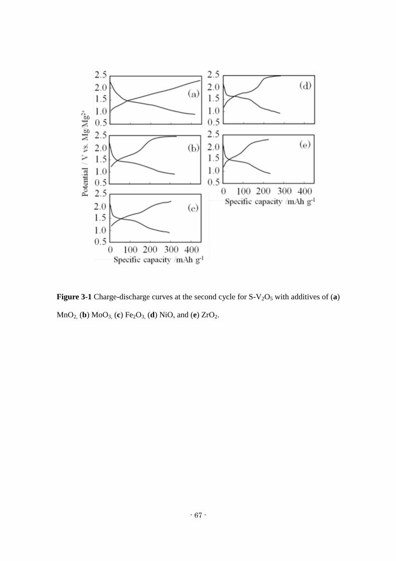
Figure 3-1 shows charge-discharge capacity curves for the batteries containing metal
oxides (MnO2, MoO3, Fe2O3, NiO, and ZrO2) as additives, which were 420, 320, 300,
290, and 230 mAh/g, respectively. The highest capacity was obtained for the electrode
with MnO2 (SMn-V2O5). The discharge curve for SMn-V2O5 decreased linearly from
1.5 V to 0.9 V vs. Mg/Mg2+
, which demonstrates that the surface of the SMn-V2O5 was
amorphous with a structure similar to a xerogel; in this regard, it is similar to S-V2O5.
Although the discharge curve obtained with added MoO3 (Figure 3-1 (b)) decreased
linearly from 1.5 V to 0.9 V vs. Mg/Mg2+
, the charge curve showed plateau potentials at
around 1.8 V and 2.4 V. For the other electrode materials (Figure 3-1 (a), (c), (d) and
(e)), a plateau potential appeared at 1.5 V, and each of the charge-discharge curves
descended abruptly after the plateau potential. The cathode formed by the addition of
NiO had the highest plateau potential at 1.65 V, different from the other electrode
materials. This result shows that the addition of NiO may improve the high-voltage
characteristics of the electrode material. Metal oxides other than MnO2 inhibited the
formation of an S-V2O5 amorphous structure and showed a plateau potential.
- 67 -
Figure 3-1 Charge-discharge curves at the second cycle for S-V2O5 with additives of (a)
MnO2, (b) MoO3, (c) Fe2O3, (d) NiO, and (e) ZrO2.
- 68 -
3.3.2 Structural Analysis
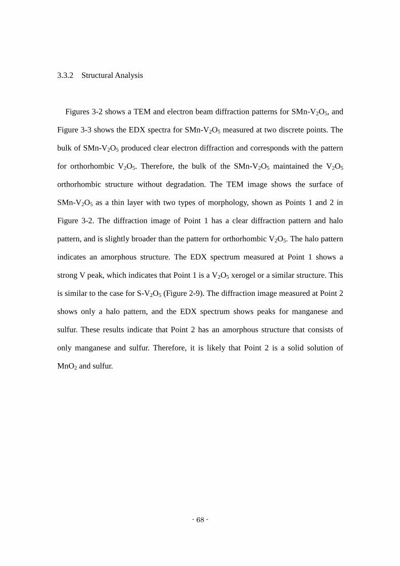
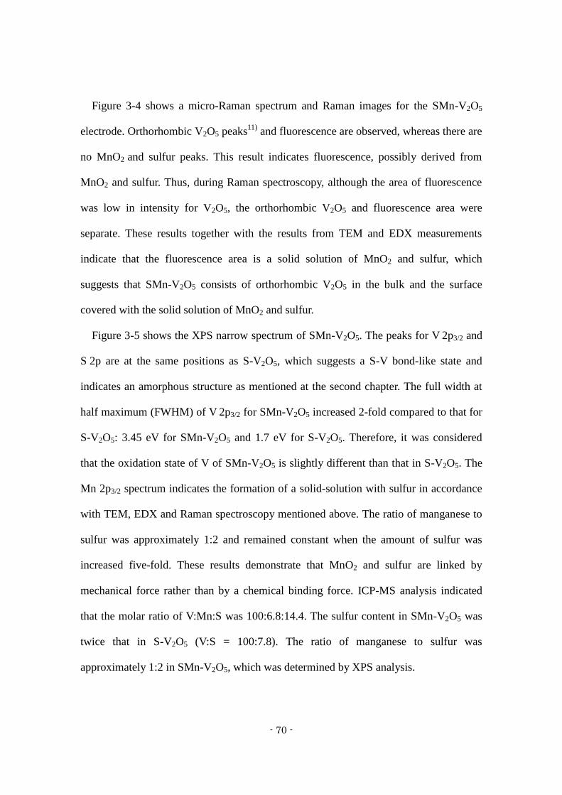
Figures 3-2 shows a TEM and electron beam diffraction patterns for SMn-V2O5, and
Figure 3-3 shows the EDX spectra for SMn-V2O5 measured at two discrete points. The
bulk of SMn-V2O5 produced clear electron diffraction and corresponds with the pattern
for orthorhombic V2O5. Therefore, the bulk of the SMn-V2O5 maintained the V2O5
orthorhombic structure without degradation. The TEM image shows the surface of
SMn-V2O5 as a thin layer with two types of morphology, shown as Points 1 and 2 in
Figure 3-2. The diffraction image of Point 1 has a clear diffraction pattern and halo
pattern, and is slightly broader than the pattern for orthorhombic V2O5. The halo pattern
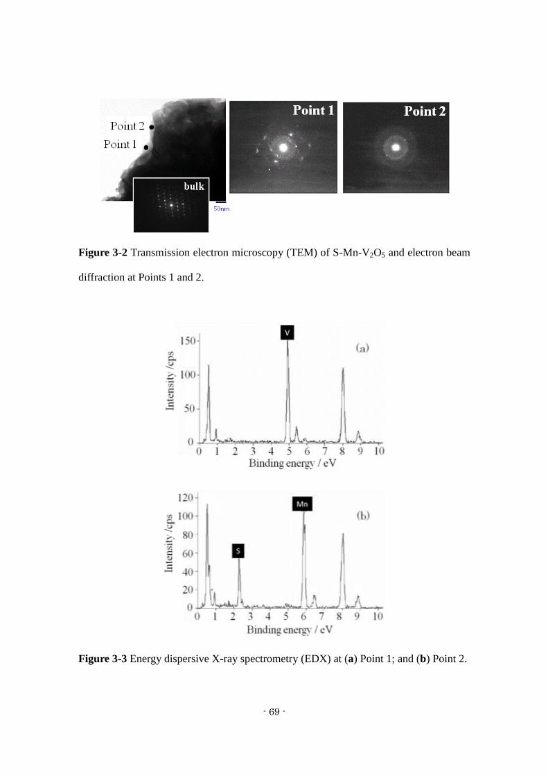
indicates an amorphous structure. The EDX spectrum measured at Point 1 shows a
strong V peak, which indicates that Point 1 is a V2O5 xerogel or a similar structure. This
is similar to the case for S-V2O5 (Figure 2-9). The diffraction image measured at Point 2
shows only a halo pattern, and the EDX spectrum shows peaks for manganese and
sulfur. These results indicate that Point 2 has an amorphous structure that consists of
only manganese and sulfur. Therefore, it is likely that Point 2 is a solid solution of
MnO2 and sulfur.
- 69 -
Figure 3-2 Transmission electron microscopy (TEM) of S-Mn-V2O5 and electron beam
diffraction at Points 1 and 2.
Figure 3-3 Energy dispersive X-ray spectrometry (EDX) at (a) Point 1; and (b) Point 2.
- 70 -
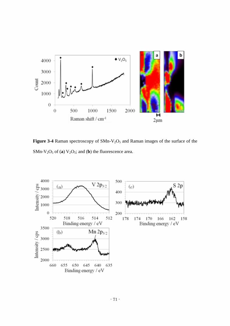
Figure 3-4 shows a micro-Raman spectrum and Raman images for the SMn-V2O5
electrode. Orthorhombic V2O5 peaks11)
and fluorescence are observed, whereas there are
no MnO2 and sulfur peaks. This result indicates fluorescence, possibly derived from
MnO2 and sulfur. Thus, during Raman spectroscopy, although the area of fluorescence
was low in intensity for V2O5, the orthorhombic V2O5 and fluorescence area were
separate. These results together with the results from TEM and EDX measurements
indicate that the fluorescence area is a solid solution of MnO2 and sulfur, which
suggests that SMn-V2O5 consists of orthorhombic V2O5 in the bulk and the surface
covered with the solid solution of MnO2 and sulfur.
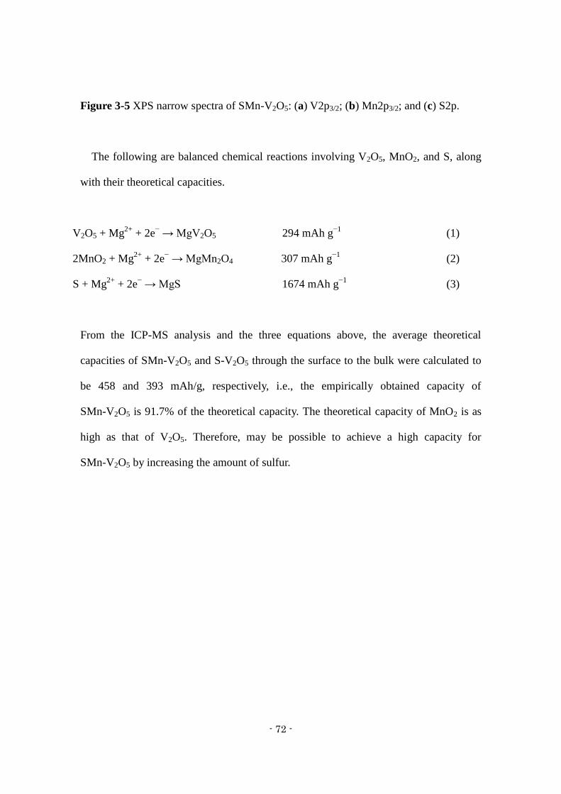
Figure 3-5 shows the XPS narrow spectrum of SMn-V2O5. The peaks for V 2p3/2 and
S 2p are at the same positions as S-V2O5, which suggests a S-V bond-like state and
indicates an amorphous structure as mentioned at the second chapter. The full width at
half maximum (FWHM) of V 2p3/2 for SMn-V2O5 increased 2-fold compared to that for
S-V2O5: 3.45 eV for SMn-V2O5 and 1.7 eV for S-V2O5. Therefore, it was considered
that the oxidation state of V of SMn-V2O5 is slightly different than that in S-V2O5. The
Mn 2p3/2 spectrum indicates the formation of a solid-solution with sulfur in accordance
with TEM, EDX and Raman spectroscopy mentioned above. The ratio of manganese to
sulfur was approximately 1:2 and remained constant when the amount of sulfur was
increased five-fold. These results demonstrate that MnO2 and sulfur are linked by
mechanical force rather than by a chemical binding force. ICP-MS analysis indicated
that the molar ratio of V:Mn:S was 100:6.8:14.4. The sulfur content in SMn-V2O5 was
twice that in S-V2O5 (V:S = 100:7.8). The ratio of manganese to sulfur was
approximately 1:2 in SMn-V2O5, which was determined by XPS analysis.
- 71 -
Figure 3-4 Raman spectroscopy of SMn-V2O5 and Raman images of the surface of the
SMn-V2O5 of (a) V2O5; and (b) the fluorescence area.
- 72 -
Figure 3-5 XPS narrow spectra of SMn-V2O5: (a) V2p3/2; (b) Mn2p3/2; and (c) S2p.
The following are balanced chemical reactions involving V2O5, MnO2, and S, along
with their theoretical capacities.
V2O5 + Mg2+
+ 2e− → MgV2O5 294 mAh g
−1 (1)
2MnO2 + Mg2+
+ 2e− → MgMn2O4 307 mAh g
−1 (2)
S + Mg2+
+ 2e− → MgS 1674 mAh g
−1 (3)
From the ICP-MS analysis and the three equations above, the average theoretical
capacities of SMn-V2O5 and S-V2O5 through the surface to the bulk were calculated to
be 458 and 393 mAh/g, respectively, i.e., the empirically obtained capacity of
SMn-V2O5 is 91.7% of the theoretical capacity. The theoretical capacity of MnO2 is as
high as that of V2O5. Therefore, may be possible to achieve a high capacity for
SMn-V2O5 by increasing the amount of sulfur.
- 73 -
3.4 Conclusions
As a cathode material for magnesium secondary batteries, S-V2O5 with an added
metal oxide was synthesized using CF-MWP and its crystal structure and electrode
characteristics were examined. The composite of V2O5, sulfur, and MnO2 (SMn-V2O5)
synthesized by CF-MWP demonstrated the highest capacity (420 mAh/g) of any of the
prepared samples. Charge-discharge curves showed that the SMn-V2O5 capacity
decreased linearly from 1.5 V to 0.9 V, whereas a plateau potential appeared at 1.5 V for
the other electrodes. This result was interpreted to indicate that only SMn-V2O5 had a
surface structure resembling a xerogel. The bulk of the SMn-V2O5 composite was
orthorhombic V2O5, while the surface showed a xerogel-like structure of V2O5 and a
solid solution of sulfur and MnO2.
- 74 -
3.5 References of Chapter 3
1) D. Aurbach, Z. Lu, A. Schechter, Y. Gofer, H. Gizbar, R. Turgeman, Y. Cohen, M.
Moshkovich and E. Levi, Nature, 407 (6805), 724–727 (2000)
2) D. Aurbach, Y. Cohen and M. Moshkovich, Electrochem. Solid State Lett., 4 (8),
A113–A116 (2001)
3) P. Novák, W. Scheifele and O. Haas, J. Power Sources, 54 (2), 479–482 (1995)
4) P. Novák, W. Scheifele, F. Joho and O. Haas, J. Electrochem. Soc., 142 (8),
2544–2550 (1995)
5) P. Novák and J. Desilvestro, J. Electrochem. Soc., 140 (1), 140–144 (1993)
6) Z. Feng, J. Yang, Y. NuLi and J. Wang, J. Power Sources, 184 (2), 604–609 (2008)
7) Z.L. Tao, L.N. Xu, X.L. Gou, J. Chen and H.T. Yuan, Chem. Commun., (18),
2080–2081 (2004)
8) A. Mitelman, M.D. Levi, E. Lancry, E. Levi and D. Aurbach, Chem. Commun., (41),
4212–4214 (2007)
9) M. Inamoto, H. Kurihara and T. Yajima, Hyomen Gijutsu, 62 (10), 516–520 (2011)
10) H. Kurihara and T. Yajima, Chem. Lett., 36 (4), 526–527 (2007)
11) R. Baddour-Hadjean, M.B. Smirnov, K.S. Smirnov, V.Y. Kazimirov, J.M.
Gallardo-Amores, U. Amador, M.E. Arroyo-de Dompablo and J.P. Pereira-Ramos,
Inorg. Chem., 51 (5), 3194–3201 (2012)
- 75 -
Chapter 4
Electrode Performance of Vanadium Pentoxide Xerogel Prepared
by Microwave Irradiation as an Active Cathode Material
4.1 Introduction
4.2 Experimental
4.3 Results and discussion
4.4 Conclusions
4.5 References
- 76 -
4.1 Introduction
Magnesium secondary batteries have been studied for a significant length of time,
and are currently being considered for next generation power storage applications. This
is partly because magnesium is low cost, safe to handle, environmentally friendly and
naturally abundant.
However, there are only a limited number of materials available for use as the
cathode in magnesium secondary batteries. Aurbach et al. reported an electrolyte
solution that allows magnesium to dissolve and deposit reversibly,1,2)
while Novak et al.
studied V2O5 as a potential cathode material.3,4)
Imamura et al. examined Mg2+
intercalation into a composite prepared from a V2O5 xerogel and carbon and determined
that the V2O5/carbon composite had a large interlayer distance and short diffusion
length compared to a V2O5 xerogel without carbon.5)
The present study focused on the
drying of this V2O5 xerogel, which is known to develop narrow interlayer distances
upon thermally-assisted drying above 50 °C.5)
Specifically, microwave (MW)
irradiation under vacuum was employed to dry the V2O5 xerogel in an attempt to
achieve greater interlayer distances than those that can be obtained by conventional heat
treatments.
- 77 -
4.2 Experimental
The V2O5 xerogel was prepared by a sol-gel process. V2O5 (1 g) was added to a 10
wt% aqueous H2O2 solution (100 mL) with electromagnetic stirring and the resulting
hydrogel was dried overnight at 70 °C in a dry oven until it became a dark brown
xerogel. Thus, the V2O5 xerogel dried just at the surface, however still wetted in the
bulk. This material was transferred to a glass vessel and subjected to MW irradiation
(500 W, 2.45 GHz) for 4 min under vacuum. For comparison purposes, V2O5 xerogels
were also dried at either 200 or 300 °C for 8 h. The structures of the dried xerogels were
examined by X-ray diffraction (XRD; Rigaku, RINT 2000).
Electrodes were prepared using a 7:2:1 (by mass) mixture of V2O5 xerogel with
acetylene black and polyvinylidene fluoride (PVdF) binder in the solvent
N-methyl-2-pyrrolidone, followed by spreading the resulting slurry (5 mg per cm2) on
carbon paper. The resulting electrodes were dried at 110 °C for 1.5 h. Cyclic
voltammetry (CV) data were obtained with three electrode cells using an
electrochemical measurement system (Hokuto Denko, HZ-3000) with Ag/AgCl as the
reference electrode and S-V2O5 prepared by our own method6)
and charged with Mg2+
ions as a counter electrode. This electrode was found to exhibit the same potential
changes as a magnesium alloy plate and thus a magnesium alloy plate was used as the
reference electrode. Electrode performance in the three electrode cell was assessed
using 0.3 M Mg(ClO4)2 dissolved in propylene carbonate (PC) as the electrolytic
solution. Charge-discharge tests were conducted between cut-off potentials of 0.9 and
2.4 V (vs. Mg/Mg2+
) at a constant current of 60 mA g-1
(0.1 C rate). All electrode cells

- 78 -
were set up under a nitrogen atmosphere in a closed container and all measurements
were conducted at room temperature (25 °C).
- 79 -
4.3 Results and Discussion
Figure 4-1 shows the XRD patterns of the V2O5 products. The pattern generated by
the xerogel dried at 300 °C for 8 h (Figure 4-1c) is generally equivalent to that of
crystalline V2O5. These results are similar to those reported by Hibino et al.7)
In contrast,
the XRD patterns of the V2O5 xerogel irradiated with MWs for 4 min (Figure 4-1a) and
the specimen dried at 200 °C for 8 h (Figure 4-1b) both exhibit a broad, intense
diffraction peak around 2θ = 7° and broad but weak peaks at approximately 23° and 31°,
indicating structurally-preserved xerogel.8)
These peaks represent the (00l), (003) and
(004) faces. The peak intensities of the MW-irradiated V2O5 are lower than those of the
heat-treated V2O5, and the diffraction peaks of the former are shifted to lower angles.
These results suggest that MW irradiation resulted in a lower degree of crystallinity and
longer interlayer distances than conventional heat treatment, because the MWs
selectively heat the water molecules in the xerogel. The interlayer distances as
calculated using the Bragg equation were 11.96 and 11.58 Å following MW irradiation
and heat treatment, respectively. Williamson-Hall plots of XRD peak data are provided
in Figure 4-2. The slope of the plot in the case of the V2O5 prepared by MW irradiation
is greater than that of the heat treatment sample, and so it appears that the crystal
structure of the V2O5 prepared by MW irradiation is characterized by distorted layers.
Therefore, it is believed that water of hydration is essentially instantaneously eliminated
by MW irradiation.
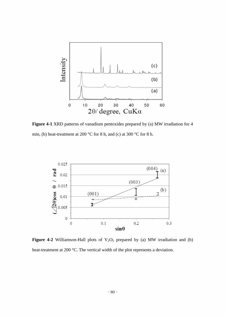
- 80 -
Figure 4-1 XRD patterns of vanadium pentoxides prepared by (a) MW irradiation for 4
min, (b) heat-treatment at 200 °C for 8 h, and (c) at 300 °C for 8 h.
Figure 4-2 Williamson-Hall plots of V2O5 prepared by (a) MW irradiation and (b)
heat-treatment at 200 °C. The vertical width of the plot represents a deviation.
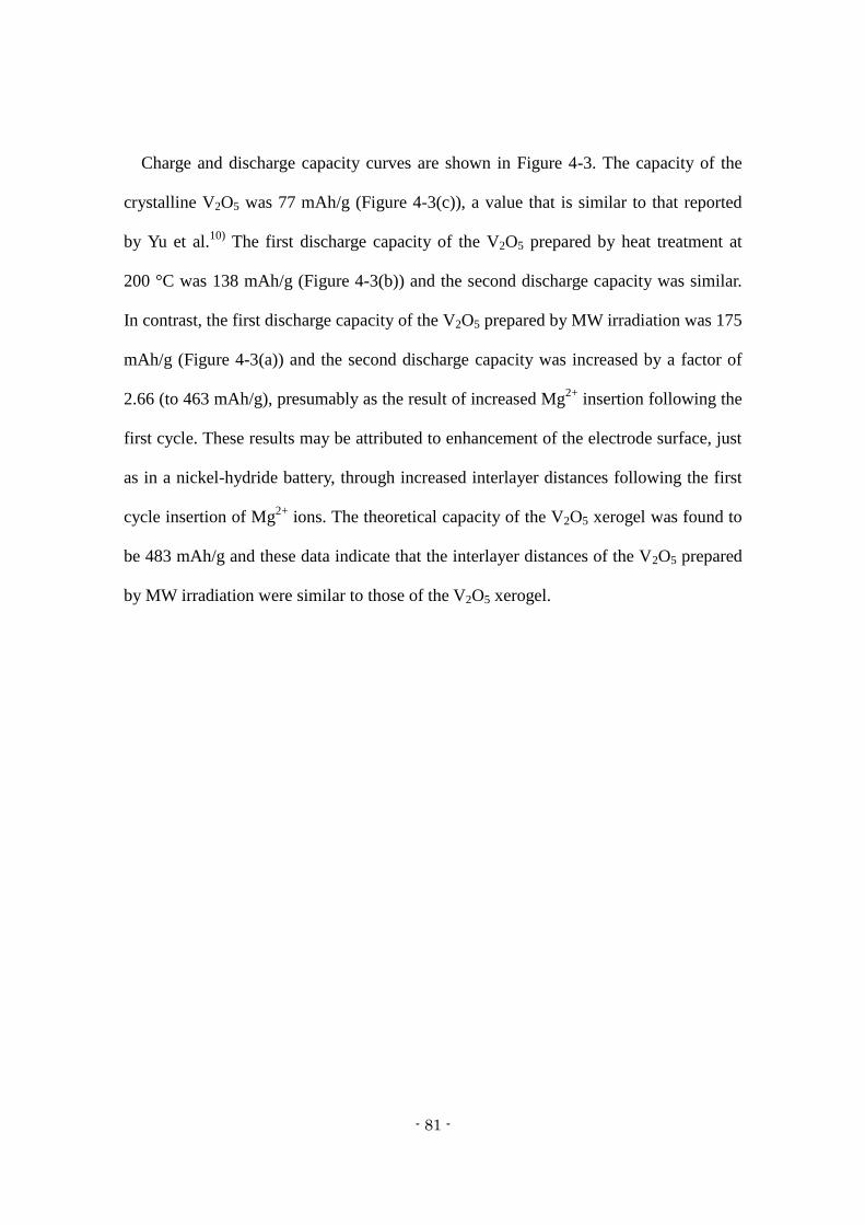
- 81 -
Charge and discharge capacity curves are shown in Figure 4-3. The capacity of the
crystalline V2O5 was 77 mAh/g (Figure 4-3(c)), a value that is similar to that reported
by Yu et al.10)
The first discharge capacity of the V2O5 prepared by heat treatment at
200 °C was 138 mAh/g (Figure 4-3(b)) and the second discharge capacity was similar.
In contrast, the first discharge capacity of the V2O5 prepared by MW irradiation was 175
mAh/g (Figure 4-3(a)) and the second discharge capacity was increased by a factor of
2.66 (to 463 mAh/g), presumably as the result of increased Mg2+
insertion following the
first cycle. These results may be attributed to enhancement of the electrode surface, just
as in a nickel-hydride battery, through increased interlayer distances following the first
cycle insertion of Mg2+
ions. The theoretical capacity of the V2O5 xerogel was found to
be 483 mAh/g and these data indicate that the interlayer distances of the V2O5 prepared
by MW irradiation were similar to those of the V2O5 xerogel.
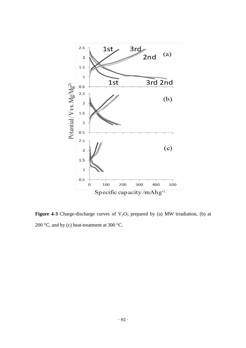
- 82 -
Figure 4-3 Charge-discharge curves of V2O5 prepared by (a) MW irradiation, (b) at
200 °C, and by (c) heat-treatment at 300 °C.
- 83 -
Figure 4-4 shows cyclic voltammograms obtained from the prepared xerogels. The
V2O5 prepared by MW irradiation generated a cathodic peak at approximately -0.15 V
vs. Ag/Ag+, and its cathodic response had an earlier onset compared with that of the
heat-treated V2O5. These results demonstrate that Mg2+
ions were inserted into the V2O5
interlayers and that MW irradiation increased the number of Mg2+
insertion sites. In
contrast, the V2O5 prepared by conventional heat treatment at 200 °C did not generate
the same type of cathodic peak, presumably because of the short interlayer distances in
this material, as previously reported by Hibino et al.9)
However, the V2O5 prepared at
300 °C produced a cathodic peak in the vicinity of -0.45 V, suggesting that Mg2+
ions
were inserted near apical oxygen atoms.6)
Therefore, the CV results are consistent with
the XRD and charge-discharge data.
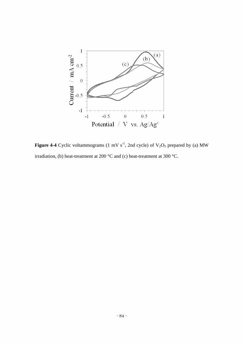
- 84 -
Figure 4-4 Cyclic voltammograms (1 mV s-1
, 2nd cycle) of V2O5 prepared by (a) MW
irradiation, (b) heat-treatment at 200 °C and (c) heat-treatment at 300 °C.
- 85 -
4.4 Conclusions
A V2O5 xerogel prepared by MW irradiation exhibited both a low degree of
crystallinity and distorted layers. Its first cycle capacity was 175 mAh/g, a value that
was almost equal to that of V2O5 prepared by conventional heat treatment. However, the
second discharge capacity of the former was 463 mAh/g, which is 2.66 times larger than
that of the latter.
- 86 -
4.5 References of Chapter 4
1) D. Aurbach, Z. Lu, A. Schechater, Y. Gofer, R. Turgeman, Y. Cohen, M.
Moshkovich and E. Levi, Nature, 407 (6805), 724-727 (2000)
2) D. Aurbach, Y. Cohen and M. Moshkovich, Electrochem. Solid State Letter, 4 (8),
A113-A116 (2001)
3) P. Novak and J. Desilvestro, J. Electrochem. Soc, 140 (1), 140-144 (1993)
4) P. Novak, W. Scheifele and O. Haas, J. Power Sources, 54 (2), 479-482 (1995)
5) D. Imamura and M. Miyayama, Solid State Ionics, 161 (1-2),173-180 (2003)
6) M. Inamoto, H. Kurihara and T. Yajima, Hyomen Gijutsu, 62 (10), 516-520 (2011)
7) M. Hibino, Y. Ikeda, Y. Noguchi and T. Kudo, Seisan Kenkyu, 52 (11), 516-522
(2000)
8) I. Stojkovic, N. Cvjeticanin, S. Markovic, M. Mitric and S. Mentus, Acta Physica
Polonica A, 117 (5), 837 (2010)
9) M. Hibino, Y. Ikeda and T. Kudo, Seisan Kenkyu, 53 (9), 432-438 (2001)
10) L. Yu and X. Zhang, Colloid Int. Sci. 278 (1), 160-165 (2004)
11) M. Hibino and T. Kudo, Hyomen Gijutsu, 36 (10), 45-53 (1998)
- 87 -
Chapter 5
Electrode Performance of Sulfur-Doped Vanadium Pentoxide Gel Composite
Cathode Materials
5.1 Introduction
5.2 Experimental
5.2.1 Preparation method for key cathode material: sulfur-containing V2O5 gel
5.2.2 Electrochemical analysis
5.3 Results and discussion
5.3.1 Structural analysis
5.3.2 Electrochemical analysis
5.4 Conclusions
5.5 References
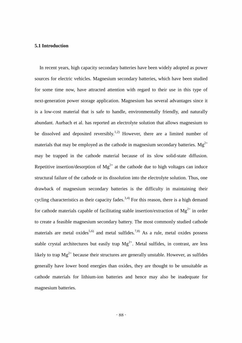
- 88 -
5.1 Introduction
In recent years, high capacity secondary batteries have been widely adopted as power
sources for electric vehicles. Magnesium secondary batteries, which have been studied
for some time now, have attracted attention with regard to their use in this type of
next-generation power storage application. Magnesium has several advantages since it
is a low-cost material that is safe to handle, environmentally friendly, and naturally
abundant. Aurbach et al. has reported an electrolyte solution that allows magnesium to
be dissolved and deposited reversibly.1,2)
However, there are a limited number of
materials that may be employed as the cathode in magnesium secondary batteries. Mg2+
may be trapped in the cathode material because of its slow solid-state diffusion.
Repetitive insertion/desorption of Mg2+
at the cathode due to high voltages can induce
structural failure of the cathode or its dissolution into the electrolyte solution. Thus, one
drawback of magnesium secondary batteries is the difficulty in maintaining their
cycling characteristics as their capacity fades.3,4)
For this reason, there is a high demand
for cathode materials capable of facilitating stable insertion/extraction of Mg2+
in order
to create a feasible magnesium secondary battery. The most commonly studied cathode
materials are metal oxides5,6)
and metal sulfides.7,8)
As a rule, metal oxides possess
stable crystal architectures but easily trap Mg2+
. Metal sulfides, in contrast, are less
likely to trap Mg2+
because their structures are generally unstable. However, as sulfides
generally have lower bond energies than oxides, they are thought to be unsuitable as
cathode materials for lithium-ion batteries and hence may also be inadequate for
magnesium batteries.
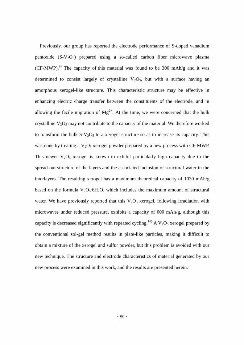
- 89 -
Previously, our group has reported the electrode performance of S-doped vanadium
pentoxide (S-V2O5) prepared using a so-called carbon fiber microwave plasma
(CF-MWP).9)
The capacity of this material was found to be 300 mAh/g and it was
determined to consist largely of crystalline V2O5, but with a surface having an
amorphous xerogel-like structure. This characteristic structure may be effective in
enhancing electric charge transfer between the constituents of the electrode, and in
allowing the facile migration of Mg2+
. At the time, we were concerned that the bulk
crystalline V2O5 may not contribute to the capacity of the material. We therefore worked
to transform the bulk S-V2O5 to a xerogel structure so as to increase its capacity. This
was done by treating a V2O5 xerogel powder prepared by a new process with CF-MWP.
This newer V2O5 xerogel is known to exhibit particularly high capacity due to the
spread-out structure of the layers and the associated inclusion of structural water in the
interlayers. The resulting xerogel has a maximum theoretical capacity of 1030 mAh/g
based on the formula V2O5∙6H2O, which includes the maximum amount of structural
water. We have previously reported that this V2O5 xerogel, following irradiation with
microwaves under reduced pressure, exhibits a capacity of 600 mAh/g, although this
capacity is decreased significantly with repeated cycling.10)
A V2O5 xerogel prepared by
the conventional sol-gel method results in plate-like particles, making it difficult to
obtain a mixture of the xerogel and sulfur powder, but this problem is avoided with our
new technique. The structure and electrode characteristics of material generated by our
new process were examined in this work, and the results are presented herein.
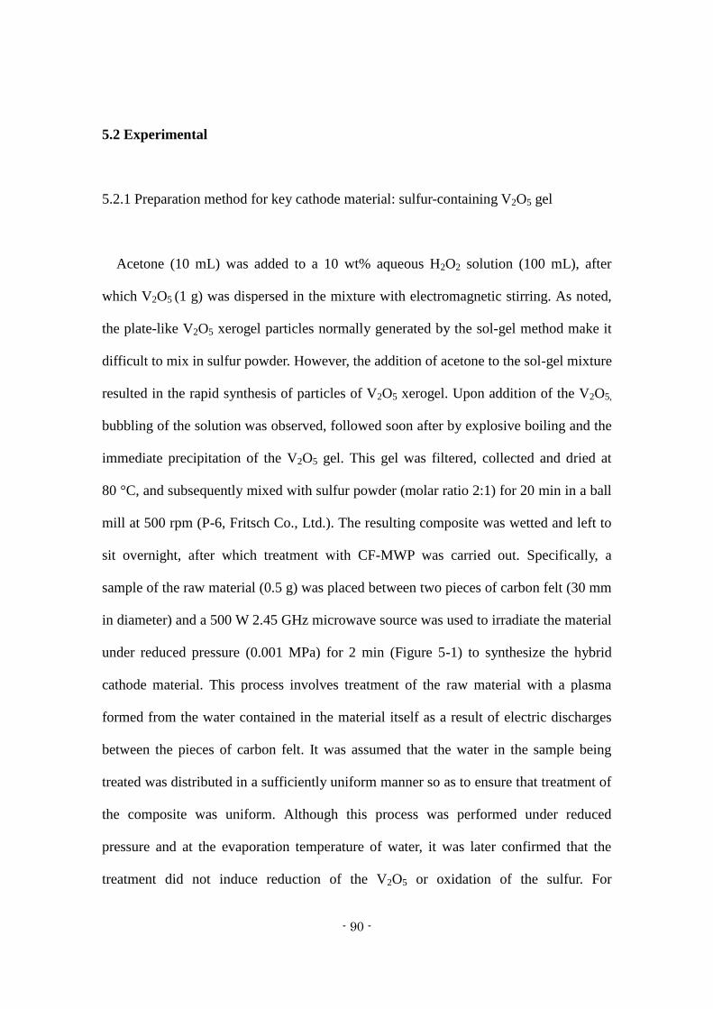
- 90 -
5.2 Experimental
5.2.1 Preparation method for key cathode material: sulfur-containing V2O5 gel
Acetone (10 mL) was added to a 10 wt% aqueous H2O2 solution (100 mL), after
which V2O5 (1 g) was dispersed in the mixture with electromagnetic stirring. As noted,
the plate-like V2O5 xerogel particles normally generated by the sol-gel method make it
difficult to mix in sulfur powder. However, the addition of acetone to the sol-gel mixture
resulted in the rapid synthesis of particles of V2O5 xerogel. Upon addition of the V2O5,
bubbling of the solution was observed, followed soon after by explosive boiling and the
immediate precipitation of the V2O5 gel. This gel was filtered, collected and dried at
80 °C, and subsequently mixed with sulfur powder (molar ratio 2:1) for 20 min in a ball
mill at 500 rpm (P-6, Fritsch Co., Ltd.). The resulting composite was wetted and left to
sit overnight, after which treatment with CF-MWP was carried out. Specifically, a
sample of the raw material (0.5 g) was placed between two pieces of carbon felt (30 mm
in diameter) and a 500 W 2.45 GHz microwave source was used to irradiate the material
under reduced pressure (0.001 MPa) for 2 min (Figure 5-1) to synthesize the hybrid
cathode material. This process involves treatment of the raw material with a plasma
formed from the water contained in the material itself as a result of electric discharges
between the pieces of carbon felt. It was assumed that the water in the sample being
treated was distributed in a sufficiently uniform manner so as to ensure that treatment of
the composite was uniform. Although this process was performed under reduced
pressure and at the evaporation temperature of water, it was later confirmed that the
treatment did not induce reduction of the V2O5 or oxidation of the sulfur. For

- 91 -
comparison purposes, a composite of V2O5 gel and sulfur was calcined at 250 °C. The
structure of the S-V2O5 gel was examined by X-ray diffraction (XRD; Rigaku,
SmartLab), scanning electron microscopy (SEM; Hitachi, SU3500) and
thermogravimetry-differential thermal analysis (TG-DTA; Rigaku, TG8120).
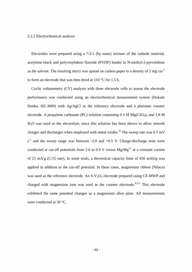
- 92 -
5.2.2 Electrochemical analysis
Electrodes were prepared using a 7:2:1 (by mass) mixture of the cathode material,
acetylene black and polyvinylidene fluoride (PVDF) binder in N-methyl-2-pyrrolidone
as the solvent. The resulting slurry was spread on carbon paper to a density of 2 mg cm-2
to form an electrode that was then dried at 110 °C for 1.5 h.
Cyclic voltammetry (CV) analysis with three electrode cells to assess the electrode
performance was conducted using an electrochemical measurement system (Hokuto
Denko, HZ-3000) with Ag/AgCl as the reference electrode and a platinum counter
electrode. A propylene carbonate (PC) solution containing 0.3 M Mg(ClO4)2 and 1.8 M
H2O was used as the electrolyte, since this solution has been shown to allow smooth
charges and discharges when employed with metal oxides.3)
The sweep rate was 0.5 mV
s-1
and the sweep range was between -2.0 and +0.5 V. Charge-discharge tests were
conducted at cut-off potentials from 2.6 to 0.9 V versus Mg/Mg2+
at a constant current
of 21 mA/g (C/15 rate). In some trials, a theoretical capacity limit of 450 mAh/g was
applied in addition to the cut-off potential. In these cases, magnesium ribbon (Nilaco)
was used as the reference electrode. An S-V2O5 electrode prepared using CF-MWP and
charged with magnesium ions was used as the counter electrode.9,11)
This electrode
exhibited the same potential changes as a magnesium alloy plate. All measurements
were conducted at 30 °C.
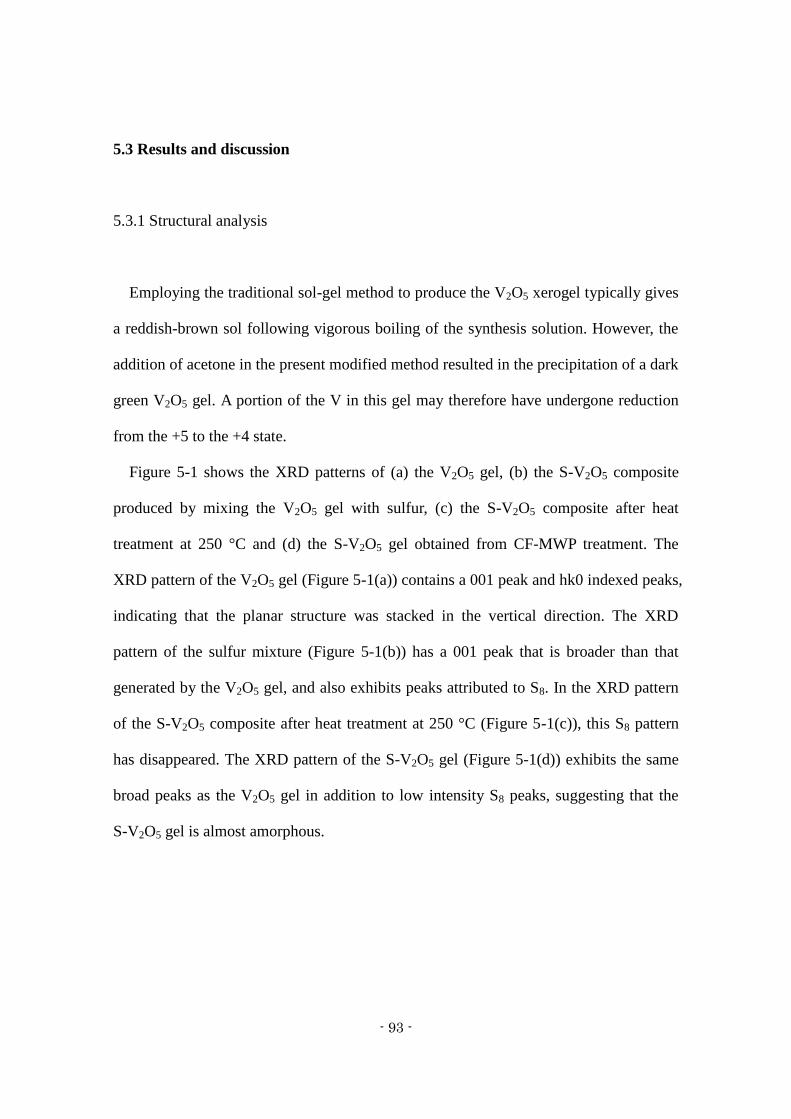
- 93 -
5.3 Results and discussion
5.3.1 Structural analysis
Employing the traditional sol-gel method to produce the V2O5 xerogel typically gives
a reddish-brown sol following vigorous boiling of the synthesis solution. However, the
addition of acetone in the present modified method resulted in the precipitation of a dark
green V2O5 gel. A portion of the V in this gel may therefore have undergone reduction
from the +5 to the +4 state.
Figure 5-1 shows the XRD patterns of (a) the V2O5 gel, (b) the S-V2O5 composite
produced by mixing the V2O5 gel with sulfur, (c) the S-V2O5 composite after heat
treatment at 250 °C and (d) the S-V2O5 gel obtained from CF-MWP treatment. The
XRD pattern of the V2O5 gel (Figure 5-1(a)) contains a 001 peak and hk0 indexed peaks,
indicating that the planar structure was stacked in the vertical direction. The XRD
pattern of the sulfur mixture (Figure 5-1(b)) has a 001 peak that is broader than that
generated by the V2O5 gel, and also exhibits peaks attributed to S8. In the XRD pattern
of the S-V2O5 composite after heat treatment at 250 °C (Figure 5-1(c)), this S8 pattern
has disappeared. The XRD pattern of the S-V2O5 gel (Figure 5-1(d)) exhibits the same
broad peaks as the V2O5 gel in addition to low intensity S8 peaks, suggesting that the
S-V2O5 gel is almost amorphous.
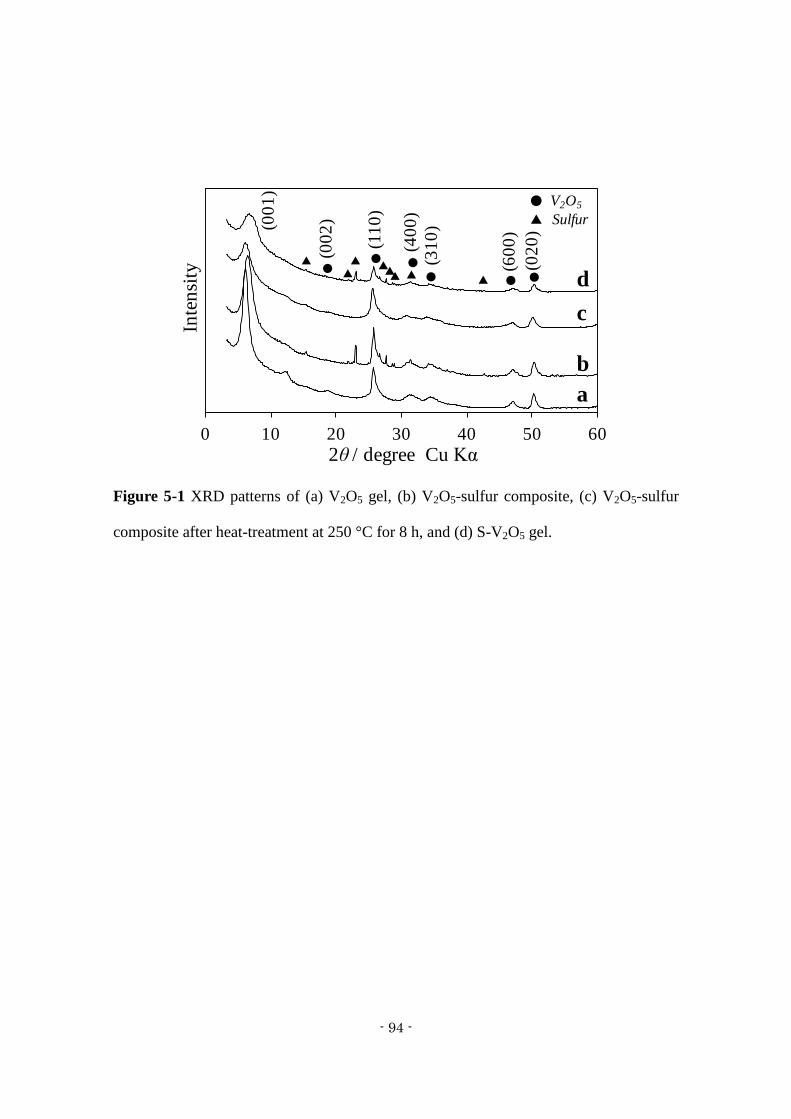
- 94 -
Figure 5-1 XRD patterns of (a) V2O5 gel, (b) V2O5-sulfur composite, (c) V2O5-sulfur
composite after heat-treatment at 250 °C for 8 h, and (d) S-V2O5 gel.
0 10 20 30 40 50 60
Inte
nsi
ty
2θ / degree Cu Kα
a
b
c
d●
● ●
● ● ●
● V2O5
▲ Sulfur
▲ ▲ ▲▲ ▲▲▲▲
(00
1)
(00
2)
(11
0)
(40
0)
(31
0)
(60
0)
(02
0)
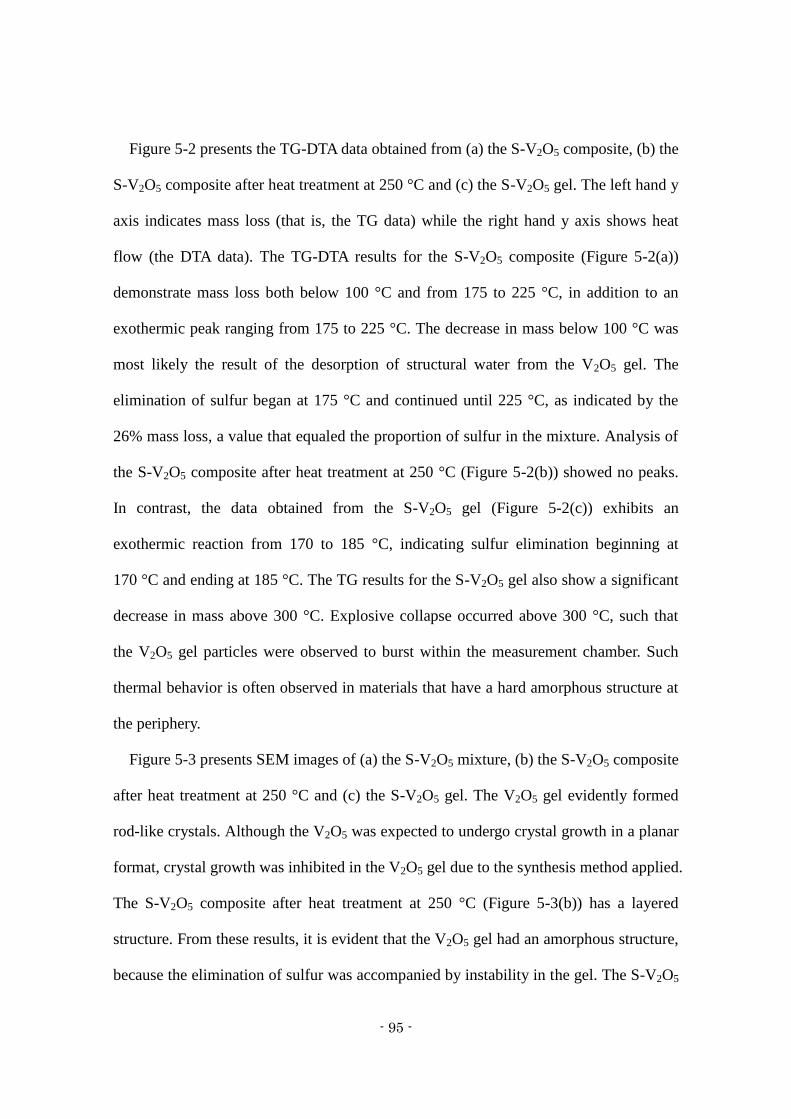
- 95 -
Figure 5-2 presents the TG-DTA data obtained from (a) the S-V2O5 composite, (b) the
S-V2O5 composite after heat treatment at 250 °C and (c) the S-V2O5 gel. The left hand y
axis indicates mass loss (that is, the TG data) while the right hand y axis shows heat
flow (the DTA data). The TG-DTA results for the S-V2O5 composite (Figure 5-2(a))
demonstrate mass loss both below 100 °C and from 175 to 225 °C, in addition to an
exothermic peak ranging from 175 to 225 °C. The decrease in mass below 100 °C was
most likely the result of the desorption of structural water from the V2O5 gel. The
elimination of sulfur began at 175 °C and continued until 225 °C, as indicated by the
26% mass loss, a value that equaled the proportion of sulfur in the mixture. Analysis of
the S-V2O5 composite after heat treatment at 250 °C (Figure 5-2(b)) showed no peaks.
In contrast, the data obtained from the S-V2O5 gel (Figure 5-2(c)) exhibits an
exothermic reaction from 170 to 185 °C, indicating sulfur elimination beginning at
170 °C and ending at 185 °C. The TG results for the S-V2O5 gel also show a significant
decrease in mass above 300 °C. Explosive collapse occurred above 300 °C, such that
the V2O5 gel particles were observed to burst within the measurement chamber. Such
thermal behavior is often observed in materials that have a hard amorphous structure at
the periphery.
Figure 5-3 presents SEM images of (a) the S-V2O5 mixture, (b) the S-V2O5 composite
after heat treatment at 250 °C and (c) the S-V2O5 gel. The V2O5 gel evidently formed
rod-like crystals. Although the V2O5 was expected to undergo crystal growth in a planar
format, crystal growth was inhibited in the V2O5 gel due to the synthesis method applied.
The S-V2O5 composite after heat treatment at 250 °C (Figure 5-3(b)) has a layered
structure. From these results, it is evident that the V2O5 gel had an amorphous structure,
because the elimination of sulfur was accompanied by instability in the gel. The S-V2O5

- 96 -
gel (Figure 5-3(c)) was found to contain angular particles. These data show that the
periphery of the S-V2O5 gel was made amorphous during treatment with the CF-MWP,
leading to explosive collapse of the gel, as observed by TG-DTA, with the formation of
an angular morphology at the surface.
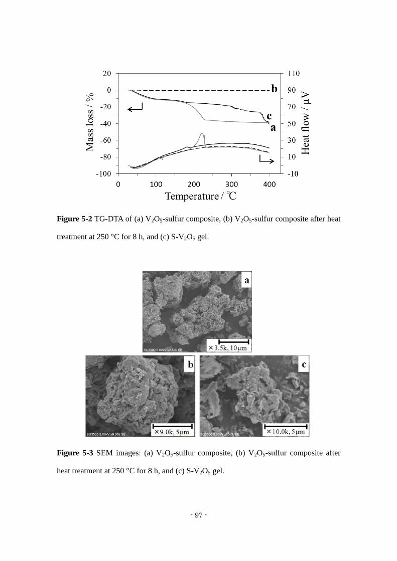
- 97 -
Figure 5-2 TG-DTA of (a) V2O5-sulfur composite, (b) V2O5-sulfur composite after heat
treatment at 250 °C for 8 h, and (c) S-V2O5 gel.
Figure 5-3 SEM images: (a) V2O5-sulfur composite, (b) V2O5-sulfur composite after
heat treatment at 250 °C for 8 h, and (c) S-V2O5 gel.
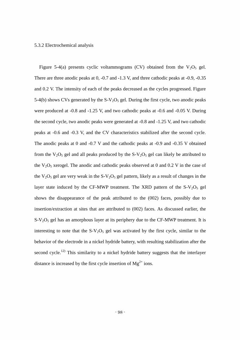
- 98 -
5.3.2 Electrochemical analysis
Figure 5-4(a) presents cyclic voltammograms (CV) obtained from the V2O5 gel.
There are three anodic peaks at 0, -0.7 and -1.3 V, and three cathodic peaks at -0.9, -0.35
and 0.2 V. The intensity of each of the peaks decreased as the cycles progressed. Figure
5-4(b) shows CVs generated by the S-V2O5 gel. During the first cycle, two anodic peaks
were produced at -0.8 and -1.25 V, and two cathodic peaks at -0.6 and -0.05 V. During
the second cycle, two anodic peaks were generated at -0.8 and -1.25 V, and two cathodic
peaks at -0.6 and -0.3 V, and the CV characteristics stabilized after the second cycle.
The anodic peaks at 0 and -0.7 V and the cathodic peaks at -0.9 and -0.35 V obtained
from the V2O5 gel and all peaks produced by the S-V2O5 gel can likely be attributed to
the V2O5 xerogel. The anodic and cathodic peaks observed at 0 and 0.2 V in the case of
the V2O5 gel are very weak in the S-V2O5 gel pattern, likely as a result of changes in the
layer state induced by the CF-MWP treatment. The XRD pattern of the S-V2O5 gel
shows the disappearance of the peak attributed to the (002) faces, possibly due to
insertion/extraction at sites that are attributed to (002) faces. As discussed earlier, the
S-V2O5 gel has an amorphous layer at its periphery due to the CF-MWP treatment. It is
interesting to note that the S-V2O5 gel was activated by the first cycle, similar to the
behavior of the electrode in a nickel hydride battery, with resulting stabilization after the
second cycle.12)
This similarity to a nickel hydride battery suggests that the interlayer
distance is increased by the first cycle insertion of Mg2+
ions.
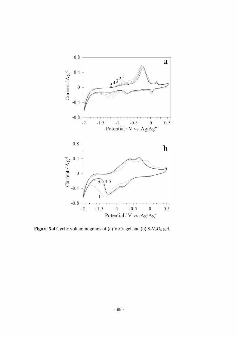
- 99 -
Figure 5-4 Cyclic voltammograms of (a) V2O5 gel and (b) S-V2O5 gel.
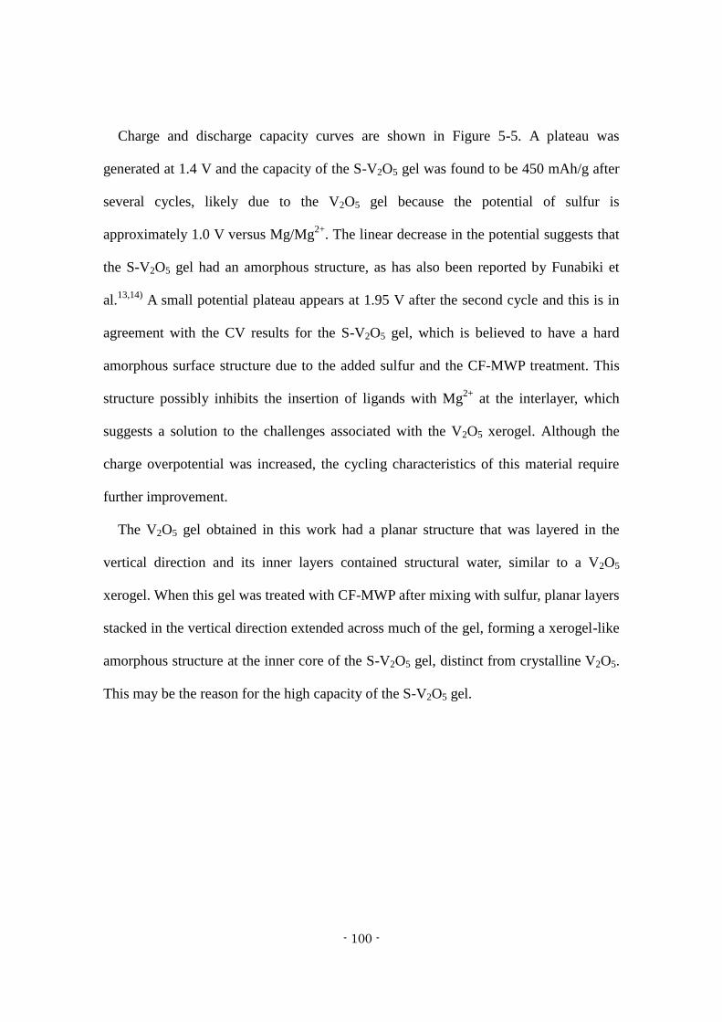
- 100 -
Charge and discharge capacity curves are shown in Figure 5-5. A plateau was
generated at 1.4 V and the capacity of the S-V2O5 gel was found to be 450 mAh/g after
several cycles, likely due to the V2O5 gel because the potential of sulfur is
approximately 1.0 V versus Mg/Mg2+
. The linear decrease in the potential suggests that
the S-V2O5 gel had an amorphous structure, as has also been reported by Funabiki et
al.13,14)
A small potential plateau appears at 1.95 V after the second cycle and this is in
agreement with the CV results for the S-V2O5 gel, which is believed to have a hard
amorphous surface structure due to the added sulfur and the CF-MWP treatment. This
structure possibly inhibits the insertion of ligands with Mg2+
at the interlayer, which
suggests a solution to the challenges associated with the V2O5 xerogel. Although the
charge overpotential was increased, the cycling characteristics of this material require
further improvement.
The V2O5 gel obtained in this work had a planar structure that was layered in the
vertical direction and its inner layers contained structural water, similar to a V2O5
xerogel. When this gel was treated with CF-MWP after mixing with sulfur, planar layers
stacked in the vertical direction extended across much of the gel, forming a xerogel-like
amorphous structure at the inner core of the S-V2O5 gel, distinct from crystalline V2O5.
This may be the reason for the high capacity of the S-V2O5 gel.
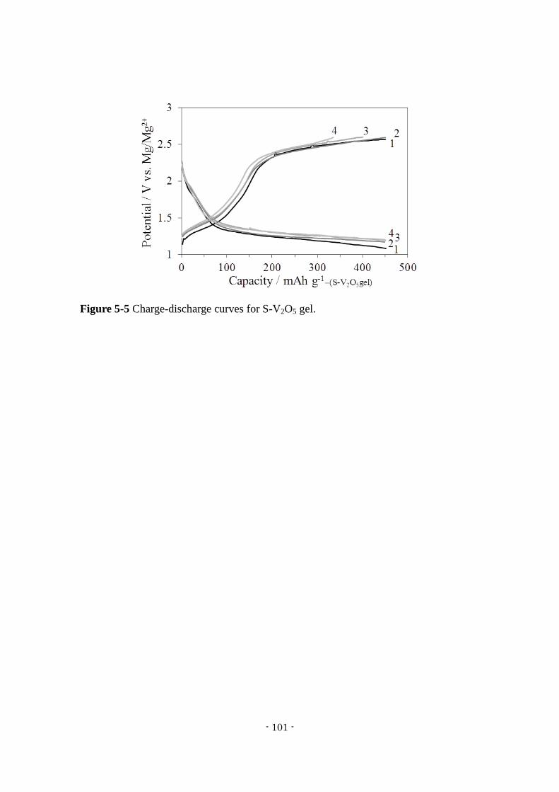
- 101 -
Figure 5-5 Charge-discharge curves for S-V2O5 gel.
- 102 -
5.4 Conclusions
This work successfully synthesized a V2O5 gel using a novel method in which
acetone and V2O5 were added to an aqueous H2O2 solution. The XRD pattern of the
V2O5 gel showed a 001 peak and hk0 indexed peaks, indicating a planar structure
stacked in the vertical direction. A S-V2O5 gel was subsequently obtained by treating a
composite of the V2O5 gel and sulfur with CF-MWP. The bulk of the S-V2O5 gel
consisted of V2O5 gel and sulfur, and the surface had an amorphous structure. The
capacity of the S-V2O5 gel was 450 mAh/g.
The effects of the addition of sulfur can be summarized as follows: (1) the transfer of
electric charge between sulfur and the V2O5 became smoother and faster and (2) the
transfer of Mg2+
was facilitated owing to the transformation of the periphery of the
S-V2O5 gel to an amorphous form after CF-MWP treatment. An extensive study of the
mechanism of the electrochemical behavior of the S-V2O5 electrode is now in progress.
Furthermore, the S-V2O5 gel is expected to show higher performance (that is, higher
capacity, higher potential and improved cycling characteristics) when doped with
magnesium or a transition metal such as nickel.
- 103 -
5.5 References of Chapter 5
1) D. Aurbach, Z. Lu, A. Schechter, Y. Gofer, H. Gizbar, R. Turgeman, Y. Cohen, M.
Moshkovich and E. Levi, Nature, 407 (6805), 724-727 (2000)
2) D. Aurbach, Y. Cohen and M. Moshkovich, Electrochem. Solid-State Lett., 4 (8),
A113-A116 (2001)
3) P. Novák, W. Scheifele, F. Joho and O. Haas, J. Electrochem. Soc., 142 (8),
2544-2550 (1995)
4) P. Novák, W. Scheifele and O. Haas, J. Power Sources, 54 (2), 479-482 (1995)
5) P. Novák and J. Desilvestro, J. Electrochem. Soc., 140 (1), 140-144 (1993)
6) Z. Feng, J. Yang, Y. NuLi and J. Wang, J. Power Sources, 184 (2), 604-609 (2008)
7) Z. L. Tao, L. N. Xu, X. L. Gou, J. Chen and H. T. Yuan, Chem. Commun. (Camb),
(18), 2080-2081 (2004)
8) A. Mitelman, M. D. Levi, E. Lancry, E. Levi and D. Aurbach, Chemical
Communications, (41), 4212-4214 (2007)
9) M. Inamoto, H. Kurihara and T. Yajima, Hyomen Gijutsu, 62 (10), 516-520 (2011)
10) M. Inamoto, H. Kurihara and T. Yajima, Electrochemistry, 80 (6), 421-422 (2012)
11) M. Inamoto, H. Kurihara and T. Yajima, Materials, 6 (10), 4514-4522 (2013)
12) F. C. Ruiz, H. A. Peretti, A. Visintin and W. E. Triaca, Int. J. Hydrogen Energy, 36
(1), 901-906 (2011)
13) A. Funabiki, H. Yasuda and M. Yamachi, Electrochemistry, 12 (71), 1081-1083
(2003)
14) H. Morimoto, D. Ikeda, A. Hayashi, M. Tatsumisago and T. Minami,
Electrochemistry, 12 (71), 1036-1038 (2003)
- 104 -
Chapter 6
General Conclusions
This work examined the feasibility of using a V2O5/sulfur composite as a magnesium
secondary battery cathode, with the aim of developing a cathode material that would
allow the repeated insertion/extraction of Mg2+
ions and would exhibit high capacity.
As reported in Chapter 2, a V2O5/sulfur synthesized by CF-MWP (S-V2O5) showed a
capacity of 300 mAh/g. It was found that the S-V2O5 particles were composed of two
parts; an inner core of rigid V2O5 crystals covered by an approximately 10 nm thick
surface layer similar to a V2O5 xerogel and incorporating sulfur. XPS analysis of the
S-V2O5 electrode surface after charge and discharge indicated the presence of an
electrolyte layer, representing a so-called solid electrolyte interphase (SEI), formed at
the interface between the electrolyte and the S-V2O5 electrode surface. This SEI plays
an important role in promoting the solid-state diffusion of Mg2+
ions.
Chapter 3 reported the ability of S-V2O5 to achieve high capacity when combined
with a metal oxide. The highest recorded capacity (420 mAh/g) was obtained upon the
addition of MnO2 to form the composite SMn-V2O5. Structural assessments showed that
- 105 -
the bulk of the SMn-V2O5 had an orthorhombic V2O5 structure, while the surface was
composed of xerogel-like V2O5 and a solid solution of MnO2 and sulfur.
Chapter 4 summarized work to prepare a V2O5 xerogel by microwave irradiation and
the results of structural and electrochemical properties assessments. X-ray diffraction
showed that the V2O5 xerogel prepared by microwave irradiation had a low degree of
crystallinity, while charge-discharge tests revealed a specific capacity of 463 mAh/g.
In Chapter 5, the preparation of a S-V2O5 gel using a new process and subsequent
evaluation of the structure and electrode performance is discussed. Structural analysis
showed that the bulk S-V2O5 gel adopted a V2O5 xerogel-like structure with a surface
layer incorporating the sulfur and in a stable planar orientation, and that the surface had
a reformed hard amorphous structure due to the CF-MWP treatment. Charge-discharge
tests determined a specific capacity of 450 mAh/g, and cyclic voltammetry found
almost perfect stability after the second cycle.
From these results, the S-V2O5 composite can be expected to function as a cathode
material via Mg2+
ion insertion/extraction based on its enhanced cycling ability and
structural stability. This study did not undertake a detailed analysis of the sulfur states in
the S-V2O5, although such states are believed to have a significant effect on ion
insertion/extraction. In future work, the effect of sulfur states on Mg2+
ion
insertion/extraction should be assessed. The results herein demonstrate the feasibility of
using magnesium secondary batteries for practical applications based on further
advances in the anode and electrolyte.
Future work should focus on enhancing the cycling characteristics of the cathode, by
inhibiting dissolution of the sulfur in the S-V2O5, and should analyze the sulfur states in

- 106 -
S-V2O5. Together with additional work regarding the electrolyte and anode, such studies
should allow the practical realization of magnesium secondary batteries.


