DEPOSITIONAL ENVIRONMENT OF THE MIDDLE PENNSYLVANIAN GRANITE WASH; LAMBERT 1, HRYHOR, AND SUNDANCE FIELDS, NORTHERN PALO DURO BASIN, OLDHAM COUNTY, TEXAS A Thesis by AMY LAURA WHARTON ' Submi'tted to the Graduate College of Texas A&M University in pyre'ia1 fulfillment of the requirement for the degree of MASTER OF SCIENCE August 1586 Major Subject: Geology
Transcript
DEPOSITIONAL ENVIRONMENT OF THE MIDDLE PENNSYLVANIAN GRANITE WASH;
LAMBERT 1, HRYHOR, AND SUNDANCE FIELDS, NORTHERN PALO DURO BASIN,
OLDHAM COUNTY, TEXAS
A Thesis
by
AMY LAURA WHARTON
' Submi'tted to the Graduate College of Texas A&M University
in pyre'ia1 fulfillment of the requirement for the degree of
MASTER OF SCIENCE
August 1586
Major Subject: Geology
DEPOSITIONAL ENVIRONMENT OF THE MIDDLE PENNSYLVANIAN GRANITE NASH;
LAMBERT 1, HRYHOR, AND SUNDANCE FIELDS, NORTHERN PALO DURO BASIN,
OLDHAM COUNTY, TEXAS
A Thesis
by
ANY LAURA NHARTON
Approved as to style and content by:
Robert R. Berg (Chairman of Committee)
James . Mazzullo (Member)
W. o glas Von Gonten (Member)
John H. pan ( ead of Department)
August 1986
ABSTRACT
Depositional Environment of the Niddle Pennsylvanian
Granite Mash; Lambert 1, Hryhor, and Sundance Fields,
Northern Palo Dura Basin, Oldham County, Texas (August 1986)
Amy Laura Mharton, B. S. . The University of Texas at Austin
Chairman of Advisory Committee: Dr. Robert R. Berg
The Lambert 1, Hryhor, and Sundance fields in Oldham County,
Texas produce oil from the Niddle Pennsylvanian Canyon granite wash.
Canyon granite wash conglomerates and sandstones have a total thick-
ness of about 450 feet (137 m) and were derived from granitic rocks
of the Bravo Dome. The sediment was transported across carbonate
platforms by streams and deposited in the Oldham Trough as fan-deltas.
The Oldham Trough is a structural depression east of the Bravo Dome
that connects the Palo Ouro and Dalhart basins. Granite wash deposits
consist primarily of imbricated gravels and cross-stratified sands
which are very poorly sorted and have a mean grain size of '1. 5 Ima.
The conglomerates and sandstones are arkoses and consist dominantly
of feldspar, granitic rock fragments, and quartz. Carbonate cement
averages 5l of the bulk composition, The association of primary
an'd secondary rock properties suggests rapid deposition and shallow
burial history.
Six depositional stages for the Middle Pennsylvanian are recog-
nized; 1) Strawn Limestone platform development and progradation,
2) Strawn granite wash progradation, 3) a second Strawn Limestone
development due to transgression and basin subsidence, 4) Canyon
Limestone platform development and progradation, 5) Canyon granite
wash progradation, and 6) a second Canyon Limestone development
due to transgression and basin subsidence, with mound-like
buildups�
:
occurring on structural highs, and shale filling the Oldham Trough.
The Cisco shales of the Middle and Late Pennsylvanian are the
probable source rocks for the Pennsylvanian oil. Temperatures and
burial depth were great enough for the shales to generate oil and
possibly wet gas. Oil accumulated in structural traps located on
upthrown blocks bounded by high-angle reverse and normal faults. The reservoir conglomerates and sandstones have an average
porosity of 18% and an average permeability of 75 md. Calculated
water resistivity is 0. 028 ohm-meter. Reasonable net pay cutoff .
values in these granite wash reservoirs are 9. 5% for porosity and
1. 5 md for permeability.
To my parents
Dr. and Mrs. James Taylor Wharton
and husband
James Burke Vanderhi11
ACKNOWLEDGEMENTS
I wish to thank all those people who have contributed to the
successful completion of this thesis. My special thanks go to Max
E. Banks, President of Baker and Taylor Drilling Co. , and Chester
Lambert, lice President who supplied all of the data examined in
this study. Mr. Banks and Mr. Lambert gave me four summers of invalu-
able idance, support and experience. Their patience and encourage-
ment have guided my career. They will always be greatly appreciated.
Dr. Robert Berg, whom I deeply respect and feel privi ledged
to have had as the chairman of my advisory committee, made this
study an enjoyable and rewarding experience. He devoted many hours
to helping me solve complicated problems. Dr. Jim Mazzullo willing'ly
shared his expertise in sedimentology and the use of his equipment.
Dr. Douglas Van Gonten contributed to the analysis of porosity and
permeability. Dr. Thomas Tieh always found time to discuss petro-
graphy and diagenesis. The support of these faculty members is
gratefully acknowledged.
I want to thank Mr. Foster Twell for his background discussions
at the initiation of this project. Thanks are also extended to
Mr. Dave Jewell , for his help in the interpretation of the seismic
data.
I am especially grateful to all of the graduate students at
ASM who made my years at the University a rewarding and fun
experience. Special thanks to Becky Lambert, Lynne Fahlquist and
Anne Linn for their friendship and support. Becky provided construc-
tive advice and ran many errands for me which helped bring this
thesis to a close. I thank Kathy Locke for identification of the
trace fossils.
Mrs. Myrna Armstrong's efficiency in typing this thesis is
greatly appreciated. Mrs. Sue Baer at Baker and Taylor will always
be remembered for her help in gathering data. Lili Lyddon and Robin
Connolly are responsible for the professional quality of the drafting.
Finally, I thank my mom and dad for their financial support
and encouragement throughout my entire education. My sisters, Tiffany
and Nanci always kept me laughing and made the stressful times a
little easier. Most of all I thank Jim, my husband, for many helpful
discussions and editing. His inspiration and love have made every-
thing worthwhile.
vi 1 1
TABLE OF CONTENTS
INTRODUCTION
Regional Structure. Regional Stratigraphy. Oil and Gas Fields of the Texas Panhandle. . . .
Granite Wash Oil Fields Lambert I, Hryhor, and Sundance Fields. .
Tectonic History. Stratigraphy. Drilling History.
Methods
CHARACTERISTICS OF THE GRANITE WASH CONGLOMERATE. . Introduction Sedimentary Structures. . Composition Texture.
INTERPRETATION.
Introduction. Alluvial Fan Deposits. Sediment Source. Depositional Environment of the Canyon Granite Wash. . Canyon Limestone. Structural Setting of the Fie'lds.
1 Structural elements of the Texas Panhandle. . Page
Regional structure map drawn on the top of the Precam- brian basement.
10
12
13
14
Structure map drawn on the top of the Canyon granite wash conglomerate
Generalized stratigraphic cross section A-A' showing the correlation of the Canyon granite wash conglom- erated from the Bravo Dome to the Oldham Trough. . . . . . . . . Gamna-ray and resistivity log response of the Granite Wash Conglomerate, Aurora 1 (H12), Hryhor field. . . . . . . . . Sedimentary structures in vertical sequence of the Canyon granite wash conglomerate in the Jay Taylor 8-1 (L2) core
Sedimentary structures in vertical sequence of the Canyon granite wash conglomerate in the Parker Creek 1 (S27) core
Sedimentary structures in vertical sequence continued from Figure 7, Parker Creek 1 (S27) core. . . , . . . . . . . , . . . . Logarithm of rock fragment (Rx)-to-feldspar (F) ratio versus logarithm of mean grain size. . . . . . . , . . . . . . . Naximum and mean grain size and generalized composi- tion plotted with gamma-ray and resistivity logs. . . . . . . , Naximum and mean grain size and generalized composi- tion plotted with gaama-ray and resistivity logs. . . . . . . , Photomicrographs of the Canyon granite wash conglomer- ate in the Jay Taylor 8-1 (L2) core taken at 25X power
Gross isopach of the Canyon granite wash interval in the Lambert I, Hryhor, and Sundance fields showing the trend and morphology of the granite wash lenses. . . , . Net isopach of the Canyon granite wash interval in the Lambert I, Hryhor, and Sundance fields showing the distribution of clean granite wash using a cutoff of 225 API units on the gramma-ray log, . . . . . . . , , . . . . . . . .
14
18
19
28
34
38
40
41
44
54
57
LIST OF FIGURES (continued)
Figure Page
16
Isopach of the Canyon Limestone interval in the Lambert I, Hryhor, and Sundance f i el d s showing the carbonate platform margin. . . . . . . Nigrated 12-fold seismic section showing the two high-angle reverse faults which form the boundaries of the Sundance and Hryhor fields. . . . . .
59
63
17 Stratigraphic cross-section B-B' showing the vertical and lateral variation of the Canyon granite wash in the Lambert 1 Field. 65
18 Stratigraphic cross-section C-C' showing the vertical and lateral variation of the Canyon granite wash across the study area. . . . . . . . . . . . . . . . . . . . . . . . . . . . . . , . . Stratigraphic cross-section D-D' showing the vertical and lateral variation of the Canyon granite wash fn the Sundance field. . . . .
68
71
20 Di agrammati c cross-section from the Bravo Dome to the Oldham Trough showing the depositional history of the Canyon and Strawn sediments in the study area. 73
21
22
23
24
25
Lopatin diagram illustrating the burial history of the Cisco Shale and its relation to hydrocarbon generation, Oldham Trough, Northern Palo Duro basin. . . . Core analysis showing porosity, permeability and fluid saturatfons in the Canyon granite wash interval, Jay Taylor 8-1 (LZ), Lambert I Field. . . . . . . . . Cross plot of porosity and bulk density from the Jay Taylor 8-1 (L2) showing estimated bulk density of the Canyon granite wash
Cross plot of permeability and porosity from the Jay Taylor 8-1 (L2) core (Figure 23) showing bimodal distribution of porosity.
Pickett plot for Jay Taylor 8 I (L2) well showing water resistivity (Rw) of 0. 0ZS ohm-m and variations in water saturation (Sw).
78
83
85
87
88
xii
LIST OF FIGURES (continued)
Figure
26
27
28
Pickett plot for Ful ton King A-2 (LS) well showing water resistivity (Rw) of 0. 028 ohm-m and variations in water saturation (Sw).
Classification of porosity data into ranges of 1 percent porosity for all samples from the Jay Taylor 8-1 (L2) core. . . . . . . . . . . . . . . . . . . . . . . . . . . . . . . . . . . Classification of porosity data into ranges of 1 percent porosity for all samples from the Parker Creek 1 (527) core.
Page
29
30
Calculation of porosity distribution from classified data for determination of cumulative capacity for the Jay Taylor B-l (L2) core.
Calculation of porosity distribution from classified data for determination of cumulative capacity for the Parker Creek 1 (S27) core.
97
99
31 Classification of permeability data into equal logrithmic intervals. 102
xi f i
LIST OF TABLES
Table
1 Stratigraphic section for the Paleozoic of the Oldham Trough, Oldham County, Texas Panhandle (modified from Handford and Dutton, 1980). . . . . . , . . . . . . .
Page
16
2 Cumulative production, April 1985, and average reservoir characteristics, Canyon Granite Wash, Oldham Trough, Northern Palo Duro Basin, Texas Panhandle. 21
3 Canyon Granite Wash completion records, Lambert I, Hryhor, and Sundance fields, Oldham County, Texas Panhandle.
4 Average compositional and textural properties of the Canyon granite wash from the Jay Taylor B-l (L2) and the Parker Creek 1 (S27) cores, Oldham County, Texas
5 Calculation of time-temperature index (TTI) for burial history of the Cisco Shale in Figure 21. . . . . . . . .
6 Average porosities and permeabilities for the Canyon granite wash, Lambert I and Sundance fields, Oldham County, Texas. Interval footage corresponds with core descriptions (Appendix III).
7 Calculation of Granite wash bulk density. . .
36
79
82
86
INTRODUCTION
The Middle Pennsylvanian granite wash is a substantial oil and
gas reservoir in the Texas Panhandle. The term "granite wash" refers
to sandstone derived from a nearby granitic source (Flawn, 1965). No surface exposures of Pennsylvanian granite wash occur in the study
area, and therefore its study depends on subsurface data: the primary
rock properties observed 0n cores, core analysis, electric logs, drill stem tests, dip logs, and seismic records.
Five granite wash fields have been discovered adjacent to the
Bravo Dome in Oldham County, Texas; the Lambert 'I, Hryhor, Sundance,
Pond, and Brandi. The section at Lambert 1, Hryhor, and Sundance
fields, which is the focus of this thesis, consists of granitic rock
fragments, feldspathic sandstones, and silty mudstones, interbedded
with limestones and shales.
The objectives of this study are interpretation of the deposi-
tional environment of the granite wash, and determination of reservoir
geometry and properties. This study is undertaken in order to explain
the origin of the reservoirs, to aid in log interpretation, and to
facilitate future prospecting for other granite wash reservoirs in
the Texas Panhandle.
This thesis fol'iows the style and format of the American Association of Petroleum Geolo fsts Bulletin.
Regional Structure
The major positive structural features of the Texas Panhandle
consist of the Amarillo Uplift, Bravo Dome, and Matador Arch
(Figure 1). The basins include the Anadarko, Dalhart and Palo Duro.
The Amarillo Uplift covers 4 counties and extends into 8 others.
It is dominated by a northwest-southeast granitic core that comes
to the surface in Oklahoma'to form the Wichita Mountains (Roth, 1949).
The Bravo Dome is an , eastern extension of the Sierra Grande Uplift
(Kluth and Coney, 1981) and occupies central and western Oldham county.
The Matador Arch separates the Palo Duro and Midland basins.
The Anadarko basin is bounded on the north by broad, flat cratonal
shelf areas, on the south by the Amarillo Uplift, and on the west
by the Cimarron Arch (Evans. 1979; Pippin, 1970; Adler et al. , 1971). The basin occupies 6 counties in the eastern Texas Panhandle and
extends into 5 other Texas counties. However, most of the basin
is in Oklahoma. The Anadarko is approximately 30, 000 feet (9150 m)
deep (Budnik and Smith, 1982), with a northwest-southeast trending
axis adjacent to the Amarillo Uplift (Nicholson, 1960). The boundary
between the Amarillo Uplift and the basin is a complicated zone of
folds and faults (Adler et al. , 1971).
The asymmetric Palo Duro basin is bounded on the northeast by
the Amarillo Uplift, on the northwest by the Bravo Dome, and on the
south by the Matador Arch. It occupies approximately 14 counties
in the southern Panhandle. It is a relatively shallow basin, approxi-
mately 11, 000 feet (3354 m) deep, and maximum Pennsylvanian deposition
occurred along a northwest trending axis (Dutton, 1980a).
I- IA
IL
DAL RT BA IN
HARTLEY
HUGOTON
GAS FIELD
OKLA ROM A
HERMAN
MOORE ANHAtDLE OIL AND GAS
FIELD I
0LDEEA
, Cl
e
DEAF SMITH
Y ce *" '-" 4 484(t(t
RANDALL
4 AI 4 D MOBEETIE FIELD 4 R+ 4 8 ( AI
»LIE F OH
AREA
. LP BASIN
A
Anticline
MATADORI ARCH Syncline
l — r—
0
0 80 KM
80 MILES
Figure l. Structural el ements of the Texas Panhandle. Ma jor struc- tural highs are shaded. The Panhandle Oil and Gas field and the Hugoton Gas field are striped. The study area and Mobeetie field are indicated by arrows (modified from Nicholson, 1960; Pippin, 1970).
The Dalhart basin is a northwestern extension of the Palo Duro
basin (Roth, 1949), and is bounded on the west by the Sierra Grande
UpIift and on the east by the Cimmarron Arch. It occupies 2 counties
in the northwest Panhandle and approximately half of Cimmarron county
in Oklahoma. The Dalhart basin is also relatively shallow, 10, 000
to 12, 000 feet (3050 to 3680 m) deep (Budni k and Smith, 1982) and
is less structurally comp1+githan the Anadarko basin (Adler et al. , 1971).
These structural features controlled the areas of erosion and
deposition from the early Pennsylvanian through the Permian. The
upi ifts eventually formed barriers to seaways that connected the
basins, and resulted fn the formation of barred and landlocked basins
(Rogatz, 1935). Restricted seaway circulation and dry climatic condi-
tions in the Permian produced the evaporite sequences which seal
the Pennsylvanian sediments.
Regional Stratigraphy
The Anadarko basin contains rocks representing most of the Paleo-
zoic Era (Evans, 1979). They are aproximately 20, 000 feet (6098 m)
thick in the Texas Panhandle and reach a maximum thickness of 40, 000
feet (12, 195 m) in Oklahoma (Adler et al. , 1971). The basin is a
significant oil and gas province. The most important reservoir rocks
for oil and gas accumulation, in order of importance, have been;
the Pennsylvanian sandstones and Iimestones; the Middle Ordovician
sandstones and carbonates; the Mississippian carbonates; the Lower
Ordovician Iimestones; and the Silurian carbonates. Both structural
and stratigraphic traps are important.
The Cambrian in the Anadarko basin consists of the Reagan
Sandstone. The Ordovician system comprises the Arbuckle Limestone
and Simpson Group sandstones, and the Viola Limestone and Sylvan
Shale. The Siluro-Devonian consists of the Hunton Group limestones.
The Mississippian contains the Kinderhookian, Osagian, Meramercian,
and Chesterian. The Pennsylvanian system comprises the Springerian
in the eastern part of the basin and also, the Morrowan, Atokan,
Des Moinesfan, Missourian, and Virgilian series occur throughout
the basin. The Permian contains the Wolfcampian, Leonardian and
Guadalupian series. Triassic, Tertiary, and Ouaternary strata uncon-
formably overlie the Permian. Other unconformities are recognized
at the base of the Silurian, Mississippian, Triassic, Tertiary, and
Ouaternary (Coasaittee of Panhandle Geological Soc. , 1955). The Palo Dura basin contains approximately 13, 700 feet (4177 m)
of Paleozoic age rocks (Birsa, 1977). The sequence has good reservoir
rocks, a high organic content, and abundant traps and seals. However,
the basin generally lacks production except around the margin. It has been suggested that the geothermal gradient may have been too
low for significant amounts of hydrocarbons to be generated (Dutton,
1980b; Fritz, 1986).
The Cambrian basa'I Hickory sandstone in the Palo Duro basin
is relatively thin and is restricted to the south centra'I and eastern
portion of the basin (Birsa, 1977). The Ordovician consists of approx-
imately 550 feet (168 m) of Ellenburger limestone. The Silurian and
Devonian are absent due to erosion and non-deposition (Dutton, 1980a). The Mississippian contains Osagian, Meramecian, and Chesterian rocks
which are simply referred to as the Mississippi lime. The Mississippi
lime is approximately 450 feet (137 m) of light-colored carbonates
(Bfrsa, 1977). All of the Pennsylvanian series are present and account
for approximately 4, 400 feet (1341 m) of the sequence. The lithologies
are highly variable and contain shale, limestone, red beds, sandstone,
and granite wash. The Permian is the thickest sequence of sediments
found in the Pa'lo Duro basin, and is approximately 7500 feet (2287 m)
thick. The Wolfcampian is primarily carbonate and shale. The
Leonardian and Guadalupian contain evaporite, red beds, and some
sandstone. Triassic, Tertiary, and quaternary strata unconformab'ly
overlie the Permian System. Other major unconformities are at the
base of the Cambrian, Ordovician. Mississippian, and Pennsylvanian
(Birsa, 1977).
The Dalhart basin is stratigraphically similar to the Palo Duro
because it was a northern extension of the basin (Dutton, 1980a). It contains the same sequence of rocks as the Palo Duro with the
following exceptions and different thicknesses (McCasland, 1980). The Ordovician also contains the Simpson sandstones and dolomites,
and the Viola limestone. The Mississippian also contains the Kinder-
hook sandstones with interbedded dolomite. The Wolfcampian sediments
reach a total thickness of more than 5000 feet (1524 m), and average
between 800 and 2100 feet (243 and 640 m) (McCasland, 1980). Triassic, Jurassic, Cretaceous, Tertiary and Ouaternary strata unconformably
overlie the Permian system. Other major unconformities are equivalent
to those in the Palo Duro basin.
Oil and Gas Fields in the Texas Panhandle
The Panhandle Oil and Gas Field is the major reservoir in the
Texas Panhandle (Figure 1). Gas was first discovered in 1918, in
Potter County at a depth of 2, 600 feet (793 m) (Rogatz, 1935), and
oil was discovered in 1921 at a depth of 2, 900 feet (884 m).
Lithologies of Wolfcampian age that produce oil and gas are dolomite,
limestone, sandstone, granite wash, and weathered granite. Local
names of the producing horizons are; Brown Dolomite, White Dolomite,
Moore County Lime, Arkosfc Dolomite, Arkosic Lime, and Granite Wash.
Uplift of the Amarillo mountains during the Atokan caused the
south edge of the Anadarko basin to shift northward producing a rever- sal of dip direction from west to southeast (Pippin, 1970). The
northwest-southeast trending granitic core was exposed and erosion resulted in the deposition of granite wash northeast into the Anadarko
basin and southwest into the Palo Duro basin (Rogatz, 1935). Granite
wash interbedded with marine muds and carbonate filled the Anadarko
basin and the uplift was covered by Wolfcampian time. Southeast
tilting of the Anadarko during the Cretaceous caused updip wedging
of Permian and Pennsylvanian sediments which formed the trap along
the west edge of the Panhandle and Hugoton fields (Pippin, 1970). The evaportic Wichita Formation formed a seal over the Wolfcampian
reservoir beds. The Panhandle field fs an anticlinal trap whose
southeastern part has a steep structural dip which gradually decreases to the northwest. The steep dip has caused the gas, oil and water
columns to cut across formation boundaries (Pippin, 1970). Progres-
sively older reservoi rs are found in the updip direction. Formation
water moves downdip and west to east causing a hydrodynamic tilt of the gas-water contact (Pippin, 1970).
The northern extension of the Panhandle field is often referred to as the Hugoton gas field (Figure 1), and is a large stratigraphic trap. The Herington and Krider formations produce gas and are equiva-
lent to the Brown Dolomite in the Texas Panhandle. Reservoir beds
thin updip and pinch-out westward. The updfp point where the reser-,
voirss
produce only water appears to be determined by an abrupt local change of porosity and permeability. However, the critical trapping mechanism is the southeastward, downdip dynamic flow of formation
water (Pippin, 1970).
Ofl production in the Texas Panhandle covers 300, 000 acres, extending approximately 125 miles (202 km) in parts of 5 Texas
counties, and gas production in the Panhandle and Hugoton fields covers 5, 000, 000 acres, extending approximately 50 miles (81 km)
in Texas and 110 miles (177 km) in Oklahoma and Kansas (Rogatz, 1935). The American Petroleum Institute's original oil-in-place estimates as of December 31, 1979 were 6, 060, 000, 000 barrels. Estimated cumula-
tive production was 1, 333, 374, 000 barrels. Ultimate recovery of natural gas for the Texas panhandle was 55, 835, 860 million cubic .
feet (American Petroleum Institute, 1980). The Pennsylvanian Morrow Sandstone is also a significant oil
reservoir in the Texas Panhandle. Oil is produced from more than
60 fields in Texas with many additional fields in Oklahoma, Kansas, and Colorado (Galloway et al. . 1983). The two most productive fie'lds in Texas are both in Ochiltree County. The Texas panhandle fields
have a cumulative production of more than 40 million barrels that
has been produced from deltaic and fluvial sandstones of the Morrow
(Galloway et al. , 1983).
Granite Wash Oil Fields
Granite wash reservoirs adjacent to the Amarillo Uplift have
been compared to modern al. 'iuvfal fans. Dutton (1982) interpreted
the granite wash reservoirs at Mobeetie field, Wheeler County
(Figure 1) as ancient fan deltas, or alluvial fans that prograded
into a body of water from an adjacent highland. Granite wash is found near the flanks of uplffts, with shales and sandstones a short
distance away and shales and thin limestones basinwards (Dutton,
1980a).
Lambert 1, Hryhor, and Sundance Fields
Granite wash reservoirs have also been discovered adjacent to the Bravo Dome in 0'ldham County. A narrow, northwest trending trough
connects the Dalhart and Palo Ouro basins in eastern Oldham and western
Potter counties, Texas (Dutton, 1980a) (Figure 2). The study area
is located within this trough, approximately 12-15 miles (19-24 km)
northeast of Vega. Texas. The trough is bounded on the west by the
Bravo Dome and on the east by the Amarillo Uplift. The intervening
low is referred to here as the Oldham trough.
10
Tectonic Histor , The crystalline basement in the Texas Panhandle
consists of Precambrian igneous rocks (Figure 2). Muehlberger et
al. , (1976) referred to the basement complex underlying the granite
wash in the study area as the "Panhandle Yolcanic Terrane" and gave
an age of 1100-1200 Ma. The Pennsylvanian granite wash was deposited
directly above weathered Precambrian basement in the Oldham trough.
The Palo Dura Basin contains Cambrian and Ordovician rocks whose
absence in the Oldham trough is probably due to pre-Pennsylvanian
erosion. Nid-Ordovician to early Mississippian rocks are also absent.
Adams (1954) postulated that a northwest trending extension of the
Transcontinental Arch, the Texas Peninsula, separated the West Texas
and Oklahoma embayments and prevented mid-Ordovician to Early Nissis-
sippian deposition on the crest of the low lying arch. By early
Mississippian time, the Peninsula ceased to be a positive element
and younger Paleozoic beds were deposited over it. The Dal hart basin and the Palo Duro basin were initiated fn
the Late Mississippian during development of the Amarillo Uplift
and associated folding, which began in the mid-Devonian (Nicholson,
1960). The Sierra Grande Uplift and Bravo Dome began to form in
Morrow-Atokan time (Bi rsa, 1977). Uplift of the Amarillo Mountains
was accomplished primarily by large-scale block faulting, which produc-
ed relatively high, rugged land masses, similar to those of the
Ancestral Rocky Nountains. Development of the intracratonic basement
uplifts may have been the result of the complex intraplate response
to the collision of North America with South America-Africa (Kiuth
and Coney, 1981). Both the Amarillo Uplift and Bravo Dome are consi-
+DALLAM
OKLAHOMA
TEXA~ ~
SHERMAN
00
DALHART
BASI »oo
HARTLEY 0 0
0 0
MOORE
0 I 4
NI 00 Bi I SS IN I
Z STUDY AREA 400 0 oo
RANDALL ' DEAF SMITH
TFS oo
PALO DURO BASIN
40 KM
40 MILES
Figure 2. Regional structure map drawn on the top of the Precambrian basement. Contour interval is 400 feet. Study area consists of three oil fields, designated by number; Lambert 1 (1), Hryhor (2), and Sundance (3) (modified from Dutton and others, 1979).
12
dered to be the major contributors of granite wash in the Texas
Panhandle during the Pennsylvanian.
Intense weathering of exposed granite highlands during the Early
and Middle Pennsylvanian resulted in granite wash accumulations on
adjacent slopes in many of the basins and troughs in Colorado.
Oklahoma, New Mexico. and Texas. . During the Pennsylvanian the study
area was located approximately 10-11' north of the equator (Schopf,
1975). The hot, humid climate contributed to the rapid weathering
of the granite highlands. The Mobeetie field of Wheeler County,
Texas (Dutton, 1982) produces oil from coarse-grained conglomerates
shed from the Amari1lo Up'fift. Erosion of the granite core of the
Pedernal Uplift in southeastern New Mexico provided coarse-grained
clastics to the Permian and Orogrande basins (Meyer, 1966). The Lambert I, Hryhor, and Sundance fields lie just east of
the Bravo Dome. High structural relief, produced by Precambrian
faulting, combined with an impermeable seal of shale or limestone,
resulted in the formation of the hydrocarbon reservoirs (Figure 3). Following deposition of the Pennsylvanian, Permian, Triassic,
and Jurassic, the Panhandle was possibly covered with Cretaceous
marine sediments. Erosion has eliminated most evidence (Eddleman,
1961), but remnants of Cretaceous rocks have been identified in the
Palo Dura Basin (Dutton and others, 1979). Movement along pre-existing faults was renewed by the Late Cretaceous Laramide orogeny. The
late Miocene-Pliocene Ogallala Formation was deposited across the
entire area .
Figure 3. Structure map drawn on the top of the Canyon granite wash conglomerate. Contour
interval is 100 feet. Cored wells are circled. The type log is from the H12 well
and indicated as a star.
+. F800
D U LGE 317
D U
3f gg
315 LGE 316 S27 ~ p'
4
+ U&
D
3QQ0
~4 4
82 ~
~O
Hq
81
80 04 03
0 0 4000 8000 ft
1000 2000 m
15
~Strati ra h . The Lambert i. Hryhor, and Sandance fields contain
Early and Nidd'le Pennsylvanian conglomerates and coarse-grained sand-
stones which were eroded from the exposed Bravo Dome and trapped
in the Oldham trough. The section unconformably overlies Precambrian
basement rock (Table 1). Carbonates were deposited intermittently,
interfingering with the clastic deposits (Figure 4). Canyon granite wash was transported across the carbonate bui'ldup and deposited on
the slope. A typical log response for the lower Pennsylvanian section is shown in Figure 5. Informal formation names used in the study
area do not necessarily correlate exactly to the Canyon and Strawn
groups.
Carbonate deposits developed around the margins of the Palo
Duro and Dalhart basins during the Pennsylvanian (Birsa, 1977). The ridge of the Amarillo Uplift was probably sufficiently high to resist marine inundation from Late Nississippian until Early Permian
time (Eddleman, 1961), while the Bravo Dome and stable shelf areas of the north and northwest Panhandle were covered earlier. Fine
clastics accumu'lated in the center of the basins. Subsidence and
renewed carbonate deposition followed in the Early Permian.
The Palo Duro and Dalhart basins were filled by the end of Wolfcampian, and the seas became landlocked (Eddleman, 1961). Evaporitic dolomite, anhydrite, and salt with interbedded red and
green shales were formed throughout the remainder of the Permian,
Triassic, and Ourassic. Due to the Laramide orogeny, at the end
of the Cretaceous, no marine deposits younger than Permian are known
in the Panhandle area (Nicholson, 1960). The Texas Panhandle has
Table 1. Stratigraphic section for the Paleozoic of the Oldham Trough, Oldham County, Texas Panhandle (modified from Handford and Button, 1980).
, Era System Series group Informal
formation name
6eneral Lithology and depositional setting
Permian
Leonardian
Clear Fork
Wichita
Tubb
Red Cave
Panhandle Limestone
red beds anhydrite and
peritidal dolomite
Paleozoic Nolfcampian Undifferentiated Brown Dolomite
Virgilian Cisco Limestone and shale Cisco shale
Pennsylvanian Missourian Canyon
OesMoinesian Strawn
Canyon Linmstone
Canyon 6ranite Nash
Strawn Limestone
Strawn 6ranite Mash
shelf and shelf-margin carbonate, basinal shale. and deltaic sandstone
Precambrian Complex of Intrusives Basement granite
Figure 4. Generalized stratigraphic granite wash conglomerate top of the Brown Dolomite. for simplicity. However, in Appendix II.
cross section A-A' showing the correlation of the Canyon
from the Bravo Dome to the Oldham Trough. The datum is the The Brown Dolomite Formation is denoted as a zone of dolomite
the zone contains several lithologies. Line of section shown
A SW A
HE
BRAVO DOME P45
AMY I 4
P55 TAYLOR E I
PSS SINQLEFOLD
OLDHAM TROUGH $40 H13
PARKER CREEK 14 AURORA 2 FEa
NEW ATLANTIS PEI
FULTON IRIS
4355 4460' 445a' 4450 4410 4403' 43a4'
SROWN DOLOMITE
'? TOP OF PENN LYANIAN '?
LIMESTONE 6 SHALE
CANYON LIMESTONE CISCO SHALE
STRAW?I
DOLOMITE
LlgggNE 6
Rl LNISSTONE
Rl SHALE
Qg GRANITE WASH
GRANITE
GAMNA
API
AURORA 1
RZD
LLS 4 J LLD
OHM M
20OO
CISCD SHALE
CANTON LIMESTONE
CANTON GRANITE WAIN
PERP: 2148-21SS IP: SS2 SOPD + NO WATER
STRAWN LIMESTONE
STRAWN GRANITE WASH
PRECAMSRIAN SASENENT
Figure 5. Gamma-ray and resistivity log response of the Granite Wash Conglomerate, Aurora 1 (H12), Hryhor field. Diagram shows the informal formation names used in mapping the fields. Location of well is shown in Figure 3.
20
been tectonically inactive since early Tertiary time.
oi I in the Canyon Granite Wash in Section 82, Block GM-5, State Capitol Lands Survey, Oldham County, Texas in Oecember, 1978. Evaluation
of electric logs led to the re-entry of a previously plugged well. The Jay Taylor A-I (Ll) was perforated at 6776-6786 feet (2066-2069 m)
and treated with 500 gallons of acid. The initial production was
477 barrels of oil/day with an API gravity of 42. 8'. Successful
completion initiated the development of the Lambert I field. Due to the success of the Lambert I field, numerous seismic
surveys were run from 1979 through 1983. Interpretation of structural highs, and normal and high-angle reverse faults led to the discovery of two additional fields, the Sundance (1981) and the Hryhor (1982). Many additional wildcat wells were drilled on fault bounded structures interpreted from seismic records. The Pond and Brandi fields were
discovered in 1983.
The Lambert I, Hryhor, and Sundance fields are structural traps (Figure 3). The depositional and tectonic history greatly influence reservoir quality (Table 2). As of August, 1985, the Lambert I field leads in cumulative production with 1. 8 million barrels of oil. The Hryhor and Sundance fields have produced 1. 2 million and 1. 0
mil'Ifon barrels of oil respectively (Table 3). Maximum thickness of the Canyon granite zone is 497 feet (151 m) and is encountered
at approximately 7250 feet (2210 m) in the Aurora 12 (H23) well. Estimated total reserves for the three fields is 6 million barrels of oil.
Table 2. Cumulative production, April 1985, and average reservoir characterisitics ~ Canyon Granite Wash, Oldham Trough, Northern Palo Ouro Basin, Texas Panhandle.
Pie 1 d
Average
Porosity 9
Average Water Oil Persmability Saturation Gravity
(Nd) (' API )
Average Oil Zone
Thickness (ft)
Number of producing
wells Area
(acres)
Cussaulative
production (Nbbl)
Estimated Total
Reserves (Mbbl)
Lambert 1 15 86
Hryhor 17 67
Sundance 19. 3 45 (includes Neptune 1 well)
48. 0
44. 5
45. 0
41. 5 87
35 12
175
259
211
1. 8
1. 2
1. 0
2. 5
2. 2
1. 3
Estimated total reserves figures from a study by Keplinger. Inc. , Apri'I 1985.
Table 3, csnyen Orant to Mash onplecton records. Lenhert I, Hryhor snd Sundanco fields, Oldhan County, Texas Panhandle.
Field Hell Csnpletian
Nell Sate Tep Can SN
Synhot (south-year) (ft) Subsea
(ft) Perforated Interest
Initial Production Sally Production February-1986
011 Mater 011 Naker bbls/day huis/day bhls/day hbls/day
Lanbert I
Hryhor
Jay Taylor 5-1 Jay Taylor O-l Jsy Taylor 0-1 Fulton-King A-I
7020-7058 7032-704I TSN-7034 7060-7105 7076-7134 7031-7NS 7NB-7050 706S-78/0 ID78-7112 7734-7740 7126-7140 I I D6-7164 7096-7162 7152-7156 7160-7176 7093-7119 7142-'7144 715$-7160
565 350 390 297
389 I
366 IN 160
9 163 572
6
0 0 0 0 0
27
0 75 23
299 24
17 225 Shut In 10-S4 Shut ln 7-83
31 125 38 78
Shut In 7-84 36
la 167 Shot Ie 7-85
23
Methods
Interpretation of the depositional environment at Lambert I and Sundance fields was based on the examination of full diameter
cores from two well s, the Jay Taylor B-I (L2) and the Parker Creek
I (527). The locations of these wells are circled in Figure 3. The slabbed cores were photographed and fully described to establish the vertical sequence' of sedimentary structures, texture, and gross
composition.
A petrographic analysis was conducted on thin sections taken
from representative intervals, normal to bedding. The analysis was '
made according to standard techniques. The grain size was determined
by long axis measurements of 100 detrital grains. The composition
was determined for each sample by a point count of 100 grains. Size influenced composition percentages; therefore, the gravels (& 2 mm)
'
were separated from the sands (& 2 ma). Results are presented as a percentage of the total composition. The detrital grains were
classified as monocrystalline quartz, feldspar, rock fragments (includ- ing polycrystalline quartz), other grains, and matrix (including clay and chlorite). Percentages were normalized after subtracting cement and thin section porosity. Coamerciai core analyses by Core
Laboratories. Inc. provided porosity and permeability measurements.
The reservoir was mapped using logs from 65 wells. The logs were interpreted to define formation boundaries, estimate shale content, and calculate porosi ties. Shale content was estimated from
the gamna-ray log. All beds within the Canyon granite wash interval with API units greater than 225 were counted as shale. Cross sections
24
were constructed across the study area, and structure and isopachous
maps were drawn to determine the morphology and structural configura- tion of the reservoir. Seismic data were interpreted to define faults.
Porosity and permeability data were classified and evaluated
in order to describe the average properties of the reservoir (Amyx,
et al. , 1960). Porosity versus bulk density was plotted from core analysis and log data to estimate grain density. True resistivity versus porosity plots were constructed to determine water saturation values (Pfckett, 1966).
25
CHARACTERISTICS OF THE CANYON GRANITE MASH CONGLONERATE
Introduction
The Canyon granite wash sediments at the Lambert 1 and Sundance
fie'Ids do not fall into any well-ordered pattern on a local scale. However, for descriptive purposes, the sediments can be divided
into four general facies; conglomerate, sandstone, mudstone, and
shale. In 140 feet (43 m) of core from the Jay Taylor B-1 (L2) '
well, approximately 23% is conglomerate, 75% sandstone, less than
1% mudstone, and 1% shale. The 42 feet (13 m) of core from the
Parker Creek 1 (S27) well contains approximately 5% conglomerate,
20% sandstone, 69% mudstone, and 6% shale. Facies are differentiated by their primary rock properties; sedimentary structures, composition,
and texture. These properties can be used to interpret the
environment of deposition and transport mechanisms.
The L2 and S27 cores contain a variety of sedimentary structures; pebble imbrication, cross-stratification, parallel lamination, convo-
luted lamination and soft-sediment deformation. The contacts between
the four facies and their associated sedimentary structures occur
apparently at random, and no ordered vertical sequence can be estab- lished for these cores. Bed set boundaries are difficult to identify. The most common sedimentary structure observed in the vertical sequence of the L2 core is cross-stratification of very coarse to fine-grained sandstone. The S27 core is dominated by mudstone,
in which the most corvaon structures are convoluted lamination and
other soft-sediment deformation features.
26
Trace fossils and fossils are scarce, but several types are
present in the silty mudstones and shales of both cores.
Composition is highly variable. Percentages of rock fragments,
fe'Idspar, and quartz are dependent on grain size. Beds containing
more gravel have a higher rock fragment percentage, and beds contain-
ing less gravel have a higher feldspar percentage.
The texture is also variable, but is dominated by very poorly-
sorted, angular and loosely-packed conglomerate and coarse-grained
sandstone.
Sedimentary Structures
The conglomerate facies contains the fewest sedimentary struc- tures. Conglomerates are of two types; structureless gravel beds
and imbricated gravel beds. The two types occur in variable vertical sequences 4 to 10 feet (1. 2 to 3. 1 m) thick. Internal lamination
is not discernable in the structure eless gravel beds (Figure 6-B). This may be the result of the grain size being too large to allow
sedimentary structures to be seen in the slabbed face of the 4-inch diameter core. Lack of fabric could also have been caused by rapid deposition (Blatt, et al. , 1980). Shale clasts are observed fn
the L2 core compressed between pebble grains (Figure 6-G). They
are identified as clasts because they are discontinuous lenses with
irregular thicknesses and outlines.
The imbricated gravel beds contain pebbles with their long
axes oriented in the same direction. Orientation of the pebble grains is produced by high flow intensities or mass emplacement
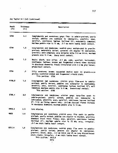
Figure 6. Sedimentary structures in vertical sequence of the Canyon granite wash
conglomerate in the Jay Taylor B-l (L2) core. The boldface letters in
the lower left corner of the photographs refer to the captions below.
6756 feet; sharp inclined contact between fine- to medium-grainded
sandstone below and pebbly sandstone above. Bedding in the fine- to
medium-grained sandstone is inclined 18'. The pebble in the structureless
cement, pebb'les are angular. fine-grained sand and silt matrix, lack
of stratification features.
6787 feet; fine- to medium-grained sandstone shows parallel, even, hori-
zontal laminae, which are in alternating 20-40 mn bands.
6794 feet; tightly cemented very coarse-grained to pebbly sandstone,
dolomite cemented fractures.
6796 feet; rock fragments and broken and fragmented crinoid stems,
suspended in silty mudstone. Coarse-grained sand shows wavy flow pattern.
6812. 5 feet; cross-stratified fine- to coarse-grained pebbly sandstone,
poorly-sorted, containing multidirectional trough or planar cress-bedding
with a truncation surface. Pebble in upper right corner is 11 sm in
long axis diameter.
6813 feet; structureless gravel, poorly-sorted. interbedded with compres-
sed shale clasts. Pebble at base of photo is 18 mn in long axis
diameter.
6823 feet; cross-stratified fine- to coarse-grained pebbly sandstone,
poorly-sorted. containing multidirectional trough or planar cross-bedding
with truncation surfaces.
J . 6839 feet; coarse-grained pebbly sandstone overlain by very fine- to
medium-grained sandstone, sharp irregular contact. Contact and bedding
in the overlying sandstone are inclined '12'.
6849 feet; black charcoal and shale flakes interlaminated with
fine-grained sandstone. Bedding in the coarse-grained sandstone above
the discontinuous shale laminae is inclined 18-20'. Pebbly sandstone
below is slightly inclined. Opposite inclination direction is probably
due to the core slab orientation.
L. 6852 feet; cross-stratified fine- to medium-grained sandstone, moderately-
sorted, containing smltidirectional trough or planar cross-bedding with
a truncation surface.
29
(Blatt, et al. , 1980). At flow depths of 1 meter, mean velocities '
of 40 to 100 cm/sec are required to transport the maximum grain
sizes of 2 to 13 mm observed in the L2 core (Hjulstrom, 1935). . '
Some of the imbricated gravel beds appear inclined 16-21'. However,
these beds contain more sand than the others and may be pebbly sand-
stone which is cross-stratified, and not inclined imbrication.
Contacts between the conglomerate facies and the mudstone and shale
facies are usual'ly sharp. The contact between the conglomerate
facies and the sandstone facies can be sharp, with the contact estab- lished by wavy, i rregu'lar shale lamination. However, the contact is usually gradational and the result of reverse or norma'1 grading. Internal contacts between the structureless gravel beds and imbricated
gravel beds are gradual.
Sandstone is the most prominent facies in the vertical sequence
of the L2 core, and the section contains the most recognizable sedi- mentary structures: cross-stratification, parallel lamination,
massive pebbly sandstone, and deformation features. Pebbles are scattered randomly throughout much of this facies. The stratified sandstone beds contain both low- and high-angle, multidirectional
cross-bedding with Ibad set thicknesses ranging from 2 to 14 feet (0. 6 to 4. 3 m). Low angle stratification is inclined 5-8' (Figure 6-L), and high angle stratification is inclined 18-20' (Figure 6A).
Nlultidirectional cross-stratification is observed at several intervals (Figure 6-F, H, and L), and was probably formed by current-transported
sediment deposited in bars containing planar and/or trough
cross-bedding. Parallel laminated sandstone occurs in 3-5 feet
30
(0. 91-1. 5 m) thick strata interbedded with the gravel beds. and
cross-stratified sandstone beds. 6rading is not apparent in the
horizontally stratified sandstones. However, lamination is observed
in 1 to 2 inch (2. 5 to 5. 0 cm) bands of alternating grain size (Figure 6-C). Pebbles as large as 25 mm are found fn medium to coarse-grained
sandstones (Figure 7-8). These sandstones which contain large pebbles
appear to lack fabric (Figure 6-A and Figure 7-8). As for the struc- tureless gravel beds in the conglomerate facies, this is probably
due to rapid deposition (Blatt. et al. . 1980). Soft sediment deforma-
tion features are mostly observed in the mudstones. However, small
displacements on synsedimentary faults also occur in the fine-grained sandstones (Figure 7-J). Contacts between the sandstone facies and mudstone facies are usually sharp (Figure 7-C, H, K, L, and
B-E).
The mudstone facies contains a substantial amount of silt and
fine-grained sandstone. Fine-grained sand lenses may be starved
ripples (Figure 7-E and K), and fine- to medium-grained sand lenses may also be starved ripples (Figure 8-A). Soft sediment deformation
is pervasive in the mudstones (Figure 7-D. E, and L). Displacements
on synsedimentary faIilts are small. probably 1 to 5 inches (2. 5
to 12. 7 cm), but difficult to measure on the face of a slabbed core. Rapid current deposition is suggested by fluid escape structures observed in the 527 core (Figure 8-D). There is little evidence of bioturbation in the sediment throughout the vertical sequence. However, a few trace fossi'ls were observed (Figure B-D), Contacts with other sedimentary facies are sharp.
Figure 7. Sedimentary structures in vertical sequence of the Canyon granite wash
conglomerate in the parka~ Creek 1 (527) core. The boldface letters in
the lower left corner of the photographs refer to the captions below.
7075. 5 feet; pebbles and coarse-grained sandstone suspended in silty mudstone, 8 mn displaceamnt on synsedimentary fault in upper portion
of photo.
7075. 7 feet; silty mudstone with suspended fine- to medium-grained sand.
Shale clast is 32 ssa long and 12 ma thick and is also suspended in the
madstone.
Figure 8. Sedimentary structures in vertical sequence continued from Figure 7, Parker Creek 1 (S27) core. The boldface letters in lower left corner of the photographs refer to the captions below.
A. 7D79 feet; silty mudstone with fine-grained sand. Sand laminae are wavy, uneven, and discontinuous, may
be starved rippled laminae. Medium-grained sand lenses interbedded with mudstone in upper portion of photo.
B. 7080 feet; medium-grained sandstone overlies fine-grained sandstone, which overlies silty mudstone. The mudstone
and fine-grained sandstone are separated by a sharp contact.
C. 7084 feet; coarse-grained sandstone grades upward into fine-grained sandstone with even, parallel, horizontal, continuous laminae. At very top of photo, faint contact is observed with coarse-grained sandstone repeated above.
D. 7085 feet; silty mudstone with very fine-grained sand
with convoluted laminae, may be a fluid-escape structure. Burrow at top left of photo.
E. 7087 feet; very fine-grained sandstone abruptly overlies black shale with sharp contact.
35
Trace fossils present in the black shales and silty mudstones
of the parker Creek 1 (S27) core include Asterosoma, Chondrites,
mint-~ero11thes(?). ~ohfomor ha(. ). ala notice s(7). ans ieichichnos. In the Jay Taylor B-1 (L2) core the only trace fossil observed is Chondrites. The known distribution of the trace fossil types seen
in the granite wash cores range from lagoonal to abysal plain; the only environment common to these fossil types is the near shore, shelf environment (Chamberlain, 1978; Locke, 1983). Other fossils observed in the L2 core were broken and fragmented crinoid stems
suspended in silty mudstone (Figure 6-E).
Composition
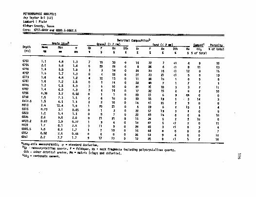
The conglomerate and sandstone compositions throughout the cored sequence are variable. Since the compositional percentages are influenced by the grain size, gravel size grains () 2 mm) are analyzed separately from sand grains (( 2 mm) (Appendix III-A and
III-B). The analyses show that the gravel population has a majority of granitic rock fragments, the sand population a majority of feld- spars, and the very fine-grained sand and coarse-silt a majority of quartz. Average detrital compositions are summarized in Table 4.
The compositions from the L2 and S27 core samples plot within the arkose field ( Folk, 1980). High granitic rock fragment and
feldspar content characterize arkoses. The L2 core has an average of 68K granitic rock fragments plus feldspar and the S27 core has
an average of 60%. The logarithmic rock fragment-to-feldspar ratio plot of the samples from the two cores shows that as grain size
Table 4. Average compositional and textural properties of the Canyon granite wash from the Jay Taylor B-l (L2) and the Parker Creek 1 (S27) cores, Oldham County, Texas.
We)1 Detrital C sition
Grain izea Gravel & 2 mn Sand & 2 nm Mean Max a Oz F Rx 0th Oz F Rx 0th C t ~Pit
Qz n monocrystailine quartz, F feldspar. Rx = rock fragsmnts including polycrystalline quartz, 0th = other detrital grains, (clays and chlorite). cC03 = csarbonate cement.
37
increases, the rock fragment-to-feldspar ratio also increases (Figure 9) (Appendix IV). Since many of. the larger gravel grains were exluded
from the thin section analyses, the actual rock fragment-to-feldspar
ratio is greater for some samples than the percentages ca 1 cul ated
from the petrology.
Monocrystalline quartz content in the L2 core varies little and averages 21% (Figure 10). Composition of the very fine-grained sand and coarse-silt in the S27 core is primarily quartz, and there- fore the core has an overall higher quartz content, averaging 25K
(Figure 11), than the L2 core, which lacks fine-grained sediment.
Monocrystalline quartz was recognized as having simple or wavy extinc- tion, no cleavage, and a uniaxial interference figure.
Feldspar composition is primarily potassium feldspar, which
is the host for the perthitic grains. The sands have very minor
percentages of plagioclase. Potassium feldspar was identified by
its gray to yellow interference colors, biaxial interference figure, and alteration features.
Rock fragments are primarily igneous rock fragments, but include small percentages of sedimentary rock fragments and polycrystalline quartz. Igneous rock fragments were recognized by the presence of quartz and feldspar combined in one grain. Most of the sedimentary
rock fragments are clay clasts which are compressed between other grains.
Accessory minerals inc] pde' muscovite, biotite, and zircon. Zircon was identified, bj, f/&: very high relief, and third or fourth-order interferehce cgi's. Oxides include anatase (Figure
Fig~re 9. Logarithm of rock fragment (Rx)-to-feldspar (F) ratio versus logarithm of mean grain size. Least squares regression line has a correlation coefficient (r) of O. B4. Oata is tabulated in Appendix IY.
Figure 10. Iiazimum and mean grain size and generalized composition plotted with gamaa-ray and res'fstivity logs. Center lithology column shows the vertical sequence of the Canyon granite wash in the Jay Taylor B-1 (L2) core.
JAY TAYLOR
75 AP I 150 GRAIN SIZE mm
16. 0 8. 0 4. 0 2. 0 1. 0 0. 5 I
MAX M EAN CORE
FT O
4 0 'o. 'o o'O'
t 0.
B-I (L2) Qrn
I IO 100 COMPOSITION 'Yo CEMENT 'Yo
0 50 100 0 40 I I I I I I I
0
GAMMA
CORE
'0 0 It (j 0', 0
O'4 . . m AO 0' ~N . , 0'. 4
Ooo. ' 00, 'O ', 0
0 'Q Qo 4
OEI o — O. G- — e-' — 3', Om
004 0 0'
'i:4
OUARTZ
ILMgl
ILP ':. SFLU ~( I I' I '; OIL
jl, WATER ~
I:
/'
TR I X MA DSPAR
/
ROCK FRAG AND
PERF 6706-6760 IPF 55580+66 MCFGPD
OMIT E DOL
GRAIN SIZE mm
8. 0 60 2. 0 I. O 0. 5 0. 25 0125
PARKER CREEK
%0 FT
I (S27) nm IO 100
0 50 IOO 0 30 ~MEAN
GAMMA
CORE
CORE
8 ILD
SFLU
ROCK FRAG AND OTHER
r
QUARTZ
MATRIX
) FELDSPAR
DOLOMITE
BIOTURBATION
KI DEFORMATION
Q MLID CLASTS PERF 7020-7058
IPF 666 80PD
Figure 11. Maximum and mean grain size and generalized composition plotted with gaImaa-ray and resistivity logs. Center lithology column shows the vertical sequence of the Canyon granite wash in the Parker Creek 1 (S27) core.
42
'l2-G) and possibly also hematite or magnetite (Figure 12-C and 12-A). The oxides were opaque and recognized by reflected light.
The matrix content of the conglomerate and coarse-grained sand-
stone beds is very low, averaging BX and 13% in the L2 and S27 cores, respectively. However, it can range as high as 29K in the
finer-grained sandstones. The matrix is the result of both detrital and authigenic processes. Detrital matrix is minor and is primarily the result of contemporaneous deposition of clay with the silt and
sand. Authigenic matrix is mainly due to the alteration of feldspars to chlorite. The chlorite is green, yellow, and brown in plain polarized light, and occurs as fibrous and blocky particles. Some
feldspars are almost completely obscured by chlorite alteration, and seri citization (Figure 12-F). Sericitization of the feldspar grain produces a di rty appearance in thin section, and renders the
feldspars easily distinguishable from quartz grains.
Evidence of feldspar dissolution is common (Figure 12-A, 8, D, and E). However. original pore space is much more abundant than
dissolved pore space. Dissolution may have been caused by the migra-
tion of formation waters. The dissolution occurs randomly, and
relatively unaltered grains exist in close proximity to dissolved
grains (Figure 12-A, B, and F). Arkoses coasnonly contain feldspars, in all stages of alteration (Blatt, et al. , 1980),
quartz overgrowths are only seen on a few very fine-grained sand particles. No overgrowths are observed on larger grains. The sand particles with quartz overgrowths were probably transported from another sour ce area and did not form in place.
Figure 12. Photomicrographs of the Canyon granite wash conglomerate in the Jay Taylor 8-1 (L2) core taken at 25x power. Blue color is epoxy and represents porosity. The bar scale represents 0. 8 millimeter. The boldface letters in the lower left corner of the photographs refer to the caption below.
A. 6751 feet; dissolved feldspar grain (Fd) in plain-polar- ized light, arrow indicates outline of the original grain. Opaque oxides may be hematite or magnetite. Some surrounding feldspar grains appear unaltered. Other feldspar grains are heavily sericitized, and
appear dirty, brownish in color.
B. 6784 feet; dissolved feldspars in cross-polarized light, dissolution occurs along selective plains of perthite. Dolomite rhombs (Dol) have replaced feldspar and have
grown into the dissolved pore space. Surrounded feldspar grains appear unaltered, or sericitized.
C. 6787 feet; opaque oxide (Ox) coats and penetrates grains along fractures. Other oxides are opaque rounded
particles. The oxides may be hematite or magnetite.
D. 6784 feet; dissolved feldspar in plain-polarized light. Feldspar grain is sericitized and partially dissolved. Corresponding photo E, in crossed-polarized light, shows dolomite rhombs that have replaced feldspar and
have grown into dissolved pore space.
E. 6784 feet; photomicrograph D in crossed-polarized light, dissolved feldspar grain, arrow indicates dolomite rhombs (Dol) replacing feldspar and growing into dissolv- ed pore space.
F. 6826 feet; dissolved feldspar in plain-polarized light, chlorite has replaced feldspar. Surrounding feldspar grains are unaltered or sericitized, but not dissolved.
G. 6826 feet; opaque oxide, anatase (A). titanium oxide (Ti02), forms in clusters in original and dissolved pore space. Surrounding feldspar grains are serici tized.
H. Bar scale represents 0. 8 millimeter.
44
45
Do'lomi te rhombs al so repl ace feldspar grains. However, only
small portions of the grains are replaced, and the rhombs seem to be found only in dissolved pore space ( Figure 12-B, E). Chlorite also occurs as alterations of the dolomite rhombs.
Pyrite fs seen in thin section with reflected light. It also occurs as nodules in the mudstones of the Parker Creek 1 (S27) core.
The amount of carbonate cement is low, averaging 4X in the L2 core and 6% in the S27 core. The cementation occurs in random
patches. There is no evidence of silica cement. Fibrous dolomite
cement is found between individual grains and in fractures in the pebbly sandstone and mudstone. Where cementation occurs, dissolution and chlorite alteration are apparently absent and grains are relative- ly unaltered. Oxides are also not present in these cemented zones. This suggests that cementation occurred before chlorite alteration. There is some evidence for several stages of cementation but the low cement percentage prevents a detailed analysis.
The Canyon granite wash characteristics suggest a relatively shallow and uncomplicated diagenetic history. The following mineralo- gical relationships recognized by Blatt et al. (1980) support this statement, 1) no formation of quartz overgrowths, 2) serici tization of K-feldspars. 3) dissolution of feldspars, and 4) precipitation of cement into pores. Other relationships which characterize deep buria'1 such as pressure solution were not seen in the two cores.
46
Texture
The textural characteristics of the Canyon granite wash are
highly variable (Figures 10, 11). The sediment is classified as
immature (Folk, 1980). The L2 and 527 cores exhibit bimodal grain size distributions with a population of gravel, and a population
of coarse to very-fine grained sand. Mean quartz sizes range from
medium-grained sand to gravel in the L2 core and very-fine grained
sand to gravel in the S27 core. The sediment is generally very
poorly-sorted. Gravel and very-coarse grained sand are mostly angular in shape. Individual beds that coarsen upward, fine upward, and
appear ungraded are present in both cores. This is probably the result of large fluctuations in discharge and other flow character- istics. The cores exhibit abrupt vertical and lateral changes in
sorting and maximum and mean grain size. The Canyon granite wash from the L2 core has average mean and
maximum grain sizes of 1. 5 mm and 6. 0 ava, respectively (Table 4). The standard deviation ranges from 0. 44 phi (well-sorted) to 2. 6
phi (very poorly-sorted). The granite wash from the S27 core is finer grained, with average mean grain size of 0. 83 xsn and average
maximum grain size of 4. 2 ma. However, the long-axis measurement
of the largest pebble observed in the core is 54 ass (Figure 7-8). The standard deviation ranges from . 05 phi (very well-sorted) to 2. 3 phi (very poorly-sorted).
The variability of grain size and composition suggests that the sediment was derived from a nearby source. The presence of fluid-escape structures, syndepositional faulting, and debris flow
47
deposits probably indicates rapid deposition and burial.
48
INTERPRETATION
Introduction
The Canyon granite wash conglomerate and sandstone consists ':
of coarse-grained debris eroded from the Bravo Dome. The sediment
was current transported across a carbonate shelf and deposited into the Oldham trough. The association of sedimentary structures, compo- .
sitions and textures suggests short transport distance from a
high-relief source area and is interpreted to be the result of fan-delta deposition. A fan-delta is an alluvial fan that progrades
into a standing body of water from an adjacent highland (McGowen,
1970; Nestcott and Ethridge, 1980). Imbricated gravel and cross- stratified bed sets are dominant and probably represent braided
stream deposits. During the transgression which followed Canyon
granite wash sedimentation, carbonate mounds developed on high-relief structures and shale filled the 0'ldham trough, eventually covering the carbonate mounds.
Alluvial Fan Deposits
Alluvial fan deposits can be divided into three depositional facies: proximal, medial, and distal. Braided stream processes are primarily responsible for transporting and depositing the sediment. Mean particle size and surface slope decrease from the head to the toe of alluvial fans (Friedman and Sanders, 1978).
The . proximal facies is located at the apex of the fan complex
where slope angles are highest. It is characterized by debris flows,
49
pebble imbrication and lack of stratification features (Klein, 1982). The sediment is poorly-sorted and shows a broad range of particle size. Particle shape is angular. Debris flow deposits are supported
by a muddy matrix, and most of the sands are grain supported. In
humid regions, stream flow dominates with less debris and mud flows
(Frledman and Sanders, 1978).
The medial facies is characterized by cross-stratification, ,
pebble imbrication, parallel lamination, and debris flows. The
cross-stratification is developed by longitudinal and transverse bars. The medial facies is better sorted than the proximal facies because of the increase in sand content, but is generally still poorly-sorted. The grave'I clasts are imbricated and the interbedded .
sandstone is parallel laminated.
The distal facies is located at the toe of the fan, and has
the lowest slope. The sands are better sorted than the medial fan. However, some sands may contain gravel. The facies is characterized by cut and fill cross-stratification, convoluted lamination, low-angle
forset beds. rip-up clasts and concretions. Pebbles are imbricated in the gravelly sand. The toe of a fan that builds out into a lake or shallow sea may be unstable and yield to sediment slumping
(Neilson, 1982).
A normal vertical sequence shows the proximal facies prograding over the medial facies, and the medial prograding over the distal facies. Coals can form on abandoned fan segments where sediment
is deposited in a lake or marsh (Klein, 1982).
50
Sediment Source
The Canyon granite wash is separated laterally from the granitic basement rocks of the Bravo Dome by platform carbonates (Figure 4). The granite wash was most likely transported across the carbonate; platform by stream channels. However, only one such channel has
been discovered, in the Nanarte Field which lies just west of the
study area on the carbonate platform. The channels may be related to the underlying Precambrian basement structure. Basement block faulting probably controlled the positions of the channels. The
'
channels would have preferentially flowed in the low areas, and
more channels have probably not been found because the grabens have
not been dri'lied.
Erosive channels of granite wash are found in several wells above the Canyon Limestone. This granite wash has been informally named here as the Nanarte granite wash (Appendix V). These channels
may have been the conduits for granite wash found farther out in the basin and may have supplied the sediment to alluvial fans recog- nized by Dutton (1980a).
Depositional Environment of the Canyon Granite Mash
The morpho'logy of the Canyon granite wash interval was determined
by constructing isopachous maps and cross sections. Cross section A-A' trends southwest-northeast and shows the characteristic geometry
of alluvial fans (Figure 4). The Strawn and Canyon granite wash
are lens-shaped bodies that thin both toward and away from the sedi- ment source. This probably reflects the continued uplift of the
51
adjacent highland during fan sedimentation (Bull, 1972). The internal
geometry of the Canyon granite wash is very complex and is probably '
due to alternating intervals of transgression and progradation during '
the uplift of the Bravo Dome. The Lambert 1, Kryhor, and Sundance
field area consists of a complex network of braided stream deposits. The interval of Canyon granite wash examined in the Jay Taylor
B-1 (L2) well represents the medial facies of an alluvial fan. Sedimentary structures. composition, and texture indicate rapid deposition from a nearby source and rapid burial. The dominant
sedimentary structures are low-angle cross-stratification of fine- 'to very coarse-grained gravelly sandstone beds. The gravel grains are imbricated and some of the interbedded sandstone beds are parallel laminated.
' Structureless gravel beds and debris-flow deposits are
also present. The cross-stratified sandstones probably represent channel and 'fongitudinal or transverse bar deposits. The interval is generally very poorly-sorted. Kowever, some beds are better sorted. Syndepositional faults indicate unstable slopes which also suggests rapid deposition and burial.
The Parker Creek 1 (S27) core represents the medial to distal fan facies. The core is dominated by marine mudstone. The most
common sedimentary structures are convo'luted lamination and other soft sediment deformation features. Conglomerate and sandstone
beds are interbedded with the mudstone . These beds are primarily cross-stratified . This interval probably represents the transition between alluvial fan and marine sedimentation. The conglomerate and sandstone is better sorted than the L2 core but is generally
52
still poorly-sorted.
The sediment distribution of the Canyon granite wash in the
Lambert I, Hr yhor, and Sundance field area illustrates the complex
nature of this deposit (Figure 13). The highly variable gross thick- ness is probably due to two factors; 1) the complex sediment distribu- tion of alluvial fan deposits, and 2) the complex structure of the area . Alluvial fan sediments consist primarily of braided stream
deposits which diverge and overlap at random. This produces highly variable thicknesses of channel fill on a local scale. Nevertheless, the entire study area has a minimum thickness of at least 200 feet (61 m) of Canyon granite wash. The interval thickness in the Lambert
I Field ranges from 236 to 378 feet (72 to 115 m); in the Hryhor
Field from 237 to 497 feet (72 to 151 m); and in the Sundance Field from 288 to greater than 401 feet (88 to &122 m) (Appendix VI).
The gross isopachous map shows the position of the carbonate platform margin and Canyon granite wash lenses extending into the Oldham Trough. The lenses reach a maximum thickness of 450 feet (137 m) and average 350 feet (106 m). The Canyon granite wash prob- ably does not extend far to the east of the Ware Jupiter 1 (P70) well. Several wells have abnormal thicknesses due to faulting, and the hatchured areas on the gross and net isopachous maps contain wells affected by faulting. These thicknesses were not used in
constructing the isopachs. A section of the Canyon granite wash
interval is repeated in the Aurora 11 (H22) well, Hryhor Field, by a high angle reverse fault. In the Lambert 1 Field, the Fulton King A-1 (L4) well is missing 125 feet of section because of a normal
Figure 13. Gross isopach of the Canyon granite wash interval in the Lambert 1, Hryhor, and Sundance
fields showing the trend and morphology of the granite wash lenses. Hachured areas contain wells whose granite wash thickness is effected by faulting and therefore not
used in mapping the trends. Contour interval is 50 feet.
LGE 31/. j-'
I I
/ j 315 LGE 316
0
zg/ /
/
\
~4 +
82 ~ L2
r ' r ~ ™~
0
88 85 l + ~83
0 4000 8000 0 5
0 4000 2000 m
55
fault.
The net isopachous map shows the same general features (Figure
14). Beds which have values on the gaama-ray log over 225 API units
were counted as shale. Shale intervals range from 18 to 85 feet (5. 5 to 26 m) in the Lambert I Field; 40 to 168 feet (12 to 51 m)
'
in the Hryhor Field; and 28 to 93 feet (8. 5 to 28 m) in the Sundance
Field (Appendix VI). Most of the shale beds are found near the
top of the granite wash section. The increase in marine shales
toward the top of the section may be the result of transgression due to decreased subsidence and decreased sediment supply. The
alternation of alluvial fan deposits and marine shale is probably
the result of lateral shifting of braided stream channels, rather than basinwide sea-level fluctuations.
Canyon Limestone
The Canyon granite wash is closely associated with the Canyon
Limestone that forms the carbonate platform across which granite wash was transported. This platform extends around the margins
of the Palo Duro and Dalhart basins (Dutton, 1980a; Birsa . 1977), as well as the Oldham Trough. Maximum thickness of Canyon platform
limestone is 712 feet (217 m) in the Amy 1 (P45) well (Figure 15). Here the Canyon Limestone rests directly on granitic basement.
In addition to forming platform areas, the Canyon Limestone
also occurs as mound-like buildups on structural highs seaward of the platform edge. Carbonate mounds are thus closely associated with producing fields. The Lambert I and Hryhor fields are both
Figure 14. Net isopach of the Canyon granite wash interval in the Lambert I, Hryhor, and Sundance
fields showing the distribution of clean granite wash using a cutoff of 225 API units
on the gamaa-ray log. Hachured areas contain wells whose granite wash thickness is effected by faulting and therefore not used in mapping the trends. Contour interval
is 50 feet.
/ J' g
gCP LGE 317' ':::. ", :.
315 LGE 316 I O
3
01
ISo
86 85 3
0 4000 0000 ft
0 1000 2000 m
Figure 15. Isopach of the Canyon Limestone interval in the Lambert I, Hryhor, and Sundance fields showing the carbonate platform margin. Mound-like buildups occur basinward of and
along the margin. The carbonate mounds generally correlate with high relief structures, and therefore correlate with the fields. Contour interval is variable.
LGE 317'
315 LGE 316 Qe
+ Q
H12
I
I I
O O
0
~ 4-
01
4 3
4000
1000
8000 ft
2000 m
60
capped by carbonate buildups with maximum thicknesses of 38 feet (1 1. 5 m) and 46 feet (14 . m) respectively. The Sundance Fie1d occurs
on the platform margin but is associated with contour irregularities that may represent buildups along the edge of the platform.
Another carbonate buildup occurs in the Exotic 1 (P50) and
New Atlantis (P59) wells. However, the Canyon granite wash is approx-
imately 150 feet (46 m) structurally lower than in the Hryhor Field and does not produce in these wells (Figure 3).
The platform is shown to trend east-west near the Lambert 1
Field. However, it may continue to trend north-south, and the 20
feet (6 m) of carbonate buildup in the Mitchell Creek 1 (P58) well
may represent another structural high.
The association of carbonate buildups with structural highs
and productive reservoirs is potentially a very powerful tool for further exploration.
Structural Setting of the Fields
The study area is structurally complex, and the interpretation of seismic sections shows the presence of numerous faults. Most
of the major faults are high-angle reverse faults, but a few normal
faults also occur. In addition, an isolith was constructed on the interval thickness form the top of the Brown Dolomite to the top of the Canyon granite wash. The map showed abrupt changes in interval thickness which were explained by fau'Iting. Major fau'its in the
study area strike north-south and may curve slightly (Figure 3).
61
A typical seismic section shows two hi gh-angle reverse faults which form the boundaries of the Hryhor and Sundance fields (Figure 16). The three fields in the study area occur on structural highs
formed by high-angle reverse and normal faults. The Lambert I Field is structurally highest with maximum elevation of -3100 feet (-945 m). The Sundance Field has a maximum elevation of -3400 feet (-1037 m)
and the Hryhor -3500 feet (-1067 m) (Figure 3).
Lambert I Field
The Lambert I Field is located on the up-thrown block of a
normal fault. Compressional forces probably produced the two succes- sive high-angle reverse faults which bound the Hryhor and Sundance
fields. The normal faulting in the Lambert I Fie'ld is probably the result of extension produced when the Sundance block bent over. Other small faults are also thought to break the continuity of the field also.
Cross-section B-B' trends north-south and shows the variability in thickness through the field due to sedimentation and faulting (Figure 17). The Canyon granite wash interval thickens across the fault from 236 feet (72 m) in the Fulton King A-1 (L4) well to 373 feet (114 m) in the Fulton King A-6 (Lg) well (Appendix VI). Increased thickness on the down-thrown side indicates movement of the fault during Niddle Pennsylvanian deposition.
Lateral and vertical correlation is difficult due to the rapid shifting of the channels and bars. The fault cuts the Fulton King A-1 (L4) well at -3054 feet (-93'l m) and shortens the section by
Figure 16. Higrated 12-fold seismic section showing the two high-angle reverse faults which form
the boundaries of the Sundance and Hryhor fields. Several minor faults cut the section but only a few are indicated. Yertical scale is two-way travel time, measured in
seconds. Line of the seismic line 4-123 is shown in Appendix II.
LINE 4-I23 W
0. 5
SUNDANCE FIELD
4 P68 638
SPRING PARKER CREEK l2 CREEK (25P NPRTHI
HRYHOR FIELD
~ ~
HI4 AURORA 3 AURORA IO
(200 SOUTH) (175 SOUTH)
0. 5
BROWN DOLOMITE
I. O
CANYON LIMESTONE I. O
PRECAMBRIAN GRANITE y.
j. I)
I;; IU'l~'~ . -- . lLIII
1. 5— ls
I& ), IMARI' I. 5
Figure 17. Stratigraphic cross-section B-B' showing the vertical and lateral variation of the Canyon granite wash in the Lambert I Field. A normal fault cuts the Fulton King A-2
(L5) well. Datum is the top of the Strawn Limestone. Location of the cross-section is shown in Appendix II. No horizontal scale.
N LAMBERT I FIELD
B 4 L II
FULTON RANCH LB LID L4 L5
FULTON KING A-5 FULTON KING A-7 FULTON KING A-I FULTON KING A-2
B'
Le FULTON KING A-G
CANYON LIMESTONE
GAMMA RESISTIVITY 0~ 0. 2 1000
CANYON GRANITE
WASH
DEEP IND
SHALLOW
STRAWN LIMESTONE
STRAWN GRANITE
~ASH (U
DATUM
PRECAMBRIAN GRANITE PERF: 6655-6730
6740-6'750 IP: 576 BOPD
+OBW
PERF' 6635-6660 6670 -6720
IP: 556 BOPD + 0 BW
66
approximately 125 feet (38 m). Restoration of the lost section results in a gross thickness of approximately 360 feet (110 m). This is in close accordance with the thickness predicted by the gross i sopachous map, which was drawn excluding the Fulton King
A-2 (L4) well (Figure '13).
The datum for cross-section B-B' is the Strawn Limestone. On the assumption that the Strawn Limestone was originally horizontal, the cross-section indicates that the surface of the Precambrian
basement has 50 to 75 feet (15 to 23 m) of relief.
Hryhor Field
The Hryhor Field is located on the upthrown side of a high-angle reverse fault. Cross-section C-C' trends northwest-southeast and
shows the high-angle reverse fault cutting the Aurora 12 (H23) well
(Figure 18). The Canyon granite wash interval thickness is 333 feet (101 m) in the Aurora 6 (H17) well. The fault cuts the Aurora
12 (H23) well at -3909 feet (-1192 m) and approximately 175 feet (54 m) of the Canyon granite wash interval is repeated. The total interval thickness is 477 feet (145 m). Removal of the repeated section leaves a gross thickness of approximately 300 feet (90 m), which correlates well with the thicknesses of nearby wells not affect- ed by faulting. The Aurora 2 (H13) may also be cut by the fault, repeating part of the Strawn granite wash interval.
Figure 18. Stratigraphic cross-section C-C' showing the vertical and lateral variation of the
Canyon granite wash across the study area. A high-angle reverse fault cuts the Aurora
12 (H23) well. The datum is the top of the Canyon Limestone. Location of the cross- section is shown in Appendix II. No horizontal scale.
NlN SUNDANCE FIELD HRYHOR FIELD LAMBERT I FIELD SE
C
Pso PARKER CAMP I
S33 PARKER CREEK 7
827 PARKER CREEK
S30 PaRKER CREEK 4
H23 AURORA 12
HI 7 AURORA 6
C L2 L5
BAY TAYLOR 8 I FULTDN KING 4 2
j MMANARTE CMEYON GRANITE WASH LIMESTONE
DATUM
OAMMA RESISTIVITY
8 i DEEP IND
R
SHALLOW
CANYON GRANITE
WASH
7- STRAWN
7 MNIESTONE
? PRE
CAIRBRIAN GRANITE
PERF 703I 7042 7048 7D58 PD F 7065 - 7070
IP 7 BDPO + 2'7 BW
SHUNWN GRAHI
PERF 7050 7I06 IP 287 BOPD
7020 — 7058 660 BOPD + 0 BW +Oew
PERF PERF: '7124 -7152 IP
IP: S64 BOPO +oew
8 N
PERF
IP 6707-6760 555 GOPD + 0 BW
6635-6660 6670-6720 sse eopo t 0 BW
69
Sundance Field
The Sundance Field also occurs on the upthrown side of a high
(Figure 19). The datum is the Canyon Limestone. The fault bounding
the west side of the Sundance Field is not evident on the
cross-section but probably occurs between the Parker Camp 1 (P60) and Parker Creek 9 (S35) wells. The cross-section shows the eastward
thickening of the Canyon granite wash interval. The fault between
the Sundance and Kryhor fields may cut the Aurora 2 (H13) well, repeating part of the Strawn granite wash interval.
Depositional History
The granite wash sediments in the Oldham Trough form thick sequences of alluvial fan deposits basinward of the carbonate
platform. Their position can be explained by a multiple sequence
of transgressions and regressions during the Middle Pennsylvanian.
A contributing factor to the depositional setting is the Bravo Dome,
which was periodically active and supplied sediment to the adjacent basins.
The depositional sequence is illustrated by a diagrammatic
cross-section which extends from the Bravo Dome to the Oldham Trough
and represents a distance of approximately 40 miles (65 km) (Figure 20). Major depositional stages are numbered from 1 (oldest) to 6 (youngest).
During high stands of sea level, the carbonate platform built upward and outward. The Strawn Limestone platform prograded across
Figure 19. Stratigraphic cross-section D-D' showing the vertical and lateral variation of the
Canyon granite wash in the Sundance field. A high-angle reverse fault cuts the section between the Parker Creek 11 (S37) and the Aurora 2 (H13) wells. The datum is the
top of the Canyon Limestone. Location of the cross-section is shown in Appendix II. No horizontal scale.
NW SUNDANCE FIELD SE
D 4 PBO
P4RKER CAMP S35
P4RKER CREEK 9 S29
PARKER CREEK 3 928
P4RKER CREEK 2 S37
PARKER CREEK 0
~ p'
H13 4URORA 2
MANARTE GRANITE WASH CANYON
LIMESTONE DATUM
GAMMA RESISTIVITY D 300 0. 2 1000
CANTON GRANITE WASH
DEEP IRD 8
SHALLOW
I
!
7
STRAWN LIMESTONE
STRAWN ~o GRANITE WASH
PRE CAMBRIAN GRANITE
PERF: 7008-7034 IP: 390 BOPD
+ 0SW
PERF: 7032-7048 IP 358 BOPD
+ 0BW
%7
PERF. 7126-7140 IP 166 BOPD
+ 238W
I
L
PERF 7168-7176 IP 454 BORD i 388W
Figure 20. Diagrammatic cross-section from the Bravo Dome to the Oldham Trough showing the deposi- tional history of the Canyon and Str'awn sediments in the study area . The circled numbers represent six depositional stages during the Middle Pennsylvanian. The
cross-section represents a distance of approximately 40 miles (65 km).
BRAVO DOME OLDHAM TROUGH
I
CANYON LIMESTONE CANYON LIMESTONE a MOUNDS I
CISCO SHALE
CANYON LIMESTONE @ ';, A
" CANYON GRANITE WASH
Q SHALE Q~. ':: GRANITE WASH
LIMESTONE Q'' GRANITE ~ GRANITE WASH CHANNELS
74
the uneven Precambrian granitic rocks (Stage 1). The cross-section, however, depicts the basement surface as horizontal for simplicity. Vertical uplift of the Bravo Dome provided a new source of coarse- clastic sediments which were carried across the platform and deposited as great fan-like sheets extending basinward from the platform slope (Stage 2).
A subsequent transgression a'llowed a second Strawn Limestone
to buildup and back over the platform (Stage 3). This three stage sequence was repeated with a Canyon platform building up and out across the underlying Strawn Limestone (Stage 4). The Canyon
Limestone probably did not prograde as far into the Oldham Trough
as the Strawn Limestone because of continuing subsidence which may
have increased water depths. Renewed uplift of the Bravo Dome provid- ed new coarse-grained debris that was carried into the basin (Stage 5). The Canyon granite wash was then transgressed by a second Canyon
Limestone and mound-like buildups formed on structural highs (Stage 6). The Canyon Limestone continued buildup of the carbonate platform and the trough was filled with shale.
This hypothesis requires great quantities of clastic sediment
transported across the broad carbonate platform. There is evidence that the transport was through channels cut on the surface of the carbonate platform. One of these may have been preserved in the Nanarte Field. The stream gradients were probably high enough to transport sediment entirely across the platform, 'leaving little evidence of channel fill. Also, the sediment that was left behind
may have accumulated in low areas which have not been drilled.
75
Additional evidence for the channeling may exist in the variable thickness of the Canyon granite wash seen on the isopachous maps,
but some thickness variation may be due to minor faulting. The
entire area was a dynamic system with uplift and erosion of the
Bravo Dome, subsidence of the basins, and small displacements on
minor faults occurring simultaneously.
Finally, faulting died out during the Late pennsylvanian as shown by the apparent decrease in the throw of the faults (Figure 16).
76
OIL ACCUNlLATION
Oil Source
Source rocks for the Pennsylvanian oil are probably the black
Cisco shales which lie directly over the Canyon Limestone and fi 1 1
the adjacent Dalhart and Palo Duro basins. Based on geochemical
evidence, Dutton (1980b) concluded that the Palo Duro Basin was
not an area of major hydrocarbon generation. However, total organic carbon (TOC) data show that higher values are associated with
Pennsylvanian and lower Permian basinal shales near the study area
(Dutton, 1980b). Maximum TOC of 2. 13% occurs at the Stanolind Herring
1 well which is 2000 feet (610 m) southeast of the Parker Camp
(P60) well. Clastic rocks that contain greater than 1. 0% TOC are considered to be good source rocks (Tfssot and Welte, 1978). In
the Stanolind Herring 1 well, the kerogen color is orange and the vitrinite reflectance is 0. 52% (Button et al. , 1982). Basinal shales of the Pennsylvanian and Wolfcampian with relatively high values of TOC that coincide with abundant lipid-rich kerogen may have gener- ated hydrocarbons. Thermal-maturity indicators studied by Dutton
et al. , (1982) show that source beds in the Pa'Io Duro Basin have
reached the threshold of the oil generation window.
Time and temperature are important in oil generation and destruc- tion. A long exposure time for a source rock at low temperatures
has the same effect as short exposure time at high temperatures. Waples (1980) applied N. V. Lopatin's method for timing of hydrocarbon
generation to the burial history of the source rock. The burial
77
history of the Cisco shale in the study area is illustrated in a
Lopatin diagram (Figure 21). A geothermal gradient of 1. 0'F/100
feet (18'C/km) was calculated from a bottom hole temperature of 149'F (65'C) in the Fulton Iris (P51) well at 8150 feet (2485 m).
The geothermal gradient in the Palo Duro Basin is 1. 1'F/100 feet (20'C/km) (Dutton, 1980b).
Lopatin's method assumes that the relationship of maturity
to time is linear, and therefore the relationship of maturity to temperature will be exponential (Waples, 1980). Time and temperature
calcuations were made from Figure 21 by estimating the time the
Ci sco shale spent in each temperature interval of 10'C (Table 5). The time was then multiplied by a temperature factor, defined by
Lopatin, to obtain a time-temperature index (TTI). Total TTI was
calculated by summing the TTI values for each interval.
Waples (1980) assigned total TTI values to different stages of hydrocarbon generation. A value of 15 total TTI marks the onset of oil generation. Peak oil generation correlates with 75 total TTI and 160 marks the end of oil generation. The upper limit for the occurrence of wet gas is about 1, 500 total TTI.
The onset of oil generation in the Cisco shale occurred approxi- mately 250 million years ago in the Late Permian, with oil being
generated until the Late Triassic when the Cisco reached a depth
in excess of 6000 feet (1830 m). Wet gas may also have been generated until the Late Cretaceous when burial was greater than 7000 feet (2134 m). Oil is produced in the Lambert 1. Hryhor, and Sundance
fields. Gas is produced in the Hebe 1 (P53) well from the Canyon
78
AGE millions of years
300 200 100
20 Cl SCO SHALE
BURIEO BY 'WOLFCAMPIAN
40 0
60
80 I-
IOO
120 I-
l40
160
O O
LL D
O
JC
O 4 Cl
EAR LY GUADALUPIAN
EROSION
BURIED BY LEONARDIAN
BURIED BY GUADALUPIAN
BURIEO BY DOCKUM OIL ~
WET GAS~
EARLY JURASSIC TO LATE MIOCENE EROSION
4 e
Z I—
6 O
180 IO
Figure 21. Lopatin diagram il'lustrating the burial history of the Cisco Shale and its relation to hydrocarbon generation, Oldham Trough, Northern Palo Duro basin. Format after Naples (1980).
79
Table 5. Calculation of time-temperature index (TTI) for burial history of the Cisco Shale in Figure 21.
Temperature Interval
Temperature Time Factor (m. y. )
Interval TTI
Total TTI
20-30'C
30-40
40-50
50-60
60-70
70-80
80-90
90-100
100-110
110-120
120-130
130-140
140-150
2-8
2-6
2-5
2-4
2-3
2-2
2-1
16
14
25
88
128
0. 02
0. 04
0. 02
0. 16
0. 50
0. 75
0. 75
7. 0
3. 0
22. 0
100. 0
704. 0
2048. 0
0. 02 '
0. 06
0. 08
0. 25
0. 75
1. 5
2. 2
12. 2
34. 2
'l 34. 2
838. 2
2886. 2
80
granite wash, and the Rodger 1 well, 3 miles (5 km) north of the
study area, has produced gas also.
Oil could have been generated ear Iier in the equivalent shales
deeper in the Dalhart and Palo Duro basins. However, Dutton's (1980b)
geochemical data suggest that these shales may not have had TOC
values, kerogen compositions, and vitrinite reflectances sufficient for hydrocarbon generation.
Trapping Mechanisms
The Cisco shales probably generated the oil produced from the
Lambert I, Hryhor, and Sundance fields. A deep down-dropped fault block that trends east-west is located approximately 1 mile (1. 6 km)
north of the study area. It contains shale that is buried about
1600 feet (488 m) deeper than the Cisco shale in the study area. This fault may have provided a migration route along with other minor faults for the oil found in the granite wash reservoirs.
The oil migrated into structurally high areas produced by fault- ing, and the faults prevented further migration. The Sundance Field is bounded by a high-angle reverse fault. The Parker Creek 9 (535), Spring Creek (P68), Connie (P47), and the Single Fold (P66) are located on the down-dropped block and do not produce.
The Hryhor Field is a'tso bounded by a high-angle reverse fault. The Aurora 12 (H23) is located on the down-dropped block and does
not produce. The Lambert I and the Hryhor fields are separated
by a structural low (Figure 3). The Lambert I is approximately
400 feet (122 m) structurally higher than the Hryhor field and
81
produces from the upthrown block of a normal fault. It is possible . '
that before movement on the normal fault began, the Hryhor and Lambert
I field were a single continuous reservoir. Subsequent deformation
may have produced the trough that now separates the fields.
Log Interpretation
Determination of porosity from well logs fs dependent upon
assumed values for matrix density and fluid density. Analyses of the L2 and S27 cores provide the opportunity to compare porosity values measured from the cores with those calculated from Formation
Density Logs. Core porosity values generally approximate true poro-
sityy
and in any case are likely to represent maximum values.
Average porosities and permeabilities measured for stratigraphic intervals form the L2 and 527 cores are presented in Table 6. The
intervals correspond to those described in Appendix III. Porosity values range from 3 to 'l6. 7 percent. Permeability ranges from 0. 1
to 613 md. Porosity and permeability are highest in gravelly sand- :
stones and conglomerates.
Porosity and permeability values for the L2 core are presented in graphic form in Figure 22. Between 6800 and 6750 feet (2073 and 2058 m) porosity and permeability generally increase upward.
Below 6800 feet, they are variable and show no discernable pattern. Oil saturation decreases from about 10% at the top of the core to 0% at the bottom. Water saturation shows a corresponding downward
increase from about 50% to 90K.
82
Table 6. Average porosities and permeabilities for the Canyon granite wash. Lambert 1 and Sundance fields, Oldham County, Texas. Interval footage correlates with core descriptions (Appendix III).
Wel I Interval (ft)
Footage (ft)
Number ~porosl t ~Pb11i tv
of Mean Range Geometric Mean Range Samples (5) (5) (md) (md)
L2
327
6751-6765
6765-6770
6770-6774
6774-6777
6777-6788
6788-6794
6794-6796
6796-6799
6799-6802
6802-6809
6809-6812
6812-6814
6814-6816. 5
6816. 5-6822
6822-6833
6833-6839. 5
6839. 5-6852
6852-6862
7032-7036
7036-7038
7038-7039
7039-7042
7042-7043
7043-7044
7044-7050
7050-7064
7064-7065. 5
7065. 5-7066
7066-7073
7073-7074
7074-7076
7076-7088
14
5
4
3
ll 6
2
3
3
7
3
2
2. 5
5. 5
11
6. 5
12. 5
10
2
1
3
1
1
6
14 1. 5
. 5
7
1
2
12
14
5
4
3 ll 6
shale
3
3
core missing
3
2
3
5
ll 7
12
10
4
shale
1
shale
1
shale
core missing
shale
shale
1
shale
4
13. 5
ll 13 13
12
9
6
12. 3
'14. 5
10. 6
12. 3 13. 5
13. 3
12 ' 2
12. 5
15. 3
12
9. 4
10. 2
'15. 2
8. 0
10. 1
8. 2-16. 1
8. 8-13 12-13. 8
11. 8-13. 9
8. 6-14. 1
3. 5-12. 6
3-9
9. 9-15. 7
13. 8-15. 2
8. 7-12. 5
6. 8-15. 6
11. 4-15. 6
8. 9-16 4-15. 9
4. 6-16. 1
14. 7-16. 7
10. 9-'I 3. 1
4. 8-6. 7
91 18-613 18. 5 4. 6-34 25 15-37
16 13-26
15 5. 8-65
3 0. 2-13
0. 6 0. 1-1. 6
24 5. 6-112
23 22-24
3. 5 1-12 14 4. 4-26
27. 5 17-53
26. 5 8-290
9 5. '1-15
7 0. 6-23 36 11-123
22 13-34
0. 3
&0. 1
0. 4
0. 2
2. 9
0. 2 0. 1-0. 3 md Millidarcy
83
PERM 1000 1
EASILITY 00 10 1
(jpd) FEET 0. 1 So
6750 «os ov(pp N jopto pop
'. 8~4$ , p', 0 apl iIo'pipe p
'oa'P jjopjj a&ppip p ~ o D jji D &0
':q' O.
— 6800'::
JAY TAYLOR B-1 (L2)
POROSITY %
20 10
WATER SATURATION % 100 80 80 40 20 0
OIL SATURATION % 0 0 20 40 80 80 100
OIL
WATER
op oop,
. 0 ' 4 ~
~w . ;Op p~;; 0
Po'. 4 A
''o, op ij0, ji .
a Opp 0'
6eSO". Osis
ii v 0 jO~i'
6900
Figure 22. Core analysis showing porosity, permeability and fluid saturations in the Canyon granite wash interval, Jay Taylor B-l (L2), Lambert 1 Field.
84
Porosities calculated from density 'logs are consistently higher than core analysis porosi ties. A cross plot of bul k density and
porosity values from both core analyses and density logs illustrates the higher log porosities, which are represented by solid squares on Figure 23. The distribution of core porosities indicates a matrix density value of about 2. 60 gm/cm3 for the granite wash. This contrasts with the matrix density value of 2. 71 gm/cm3 used in density log porosity calculations. If matrix density is calculated theoreti- cally based on the average mineralogical composition as determined in thin-section, the resulting value is approximately 2. 59 gm/cm3
(Table 7). This suggests that the matrix density of 2. 60 gm/cm3
determined from Figure 23 is close to the actual value. In addition, grain densities from the granite wash intervals in the L2 core are also in the 2. 59 to 2. 64 gm/cm3 range.
A cross plot of permeability and porosity from the Jay Taylor 8-1 (L2) core shows an abrupt change in the relationship of these two values (Figure 24). This change occurs at a porosity value of 9. 5X and a permeability value of 1. 5 md.
Formation water resistivity was determined by a cross plot method used to interpret well log data (Pickett, 1 966). Resistivity and well log porosity are plotted on logarithmic scales. The plot for the Jay Taylor 8-1 (L2) well indicates a water resistivity (Rw)
of 0. 025 ohm-meter (Figure 25). Water resistivity for the Fulton King A-2 (L5) well is 0. 028 ohm-meter (Figure 26).
Figure 23. Cross plot of porosity and bulk density from the Jay Taylor B-1 (L2) showing estimated bulk density of the Canyon granite wash. Squares indicate log data, open and closed triangles indicate porosity data from the core analysis, and bulk density data from the density log.
86
Table 7. Calculation of Granite Wash bulk density.
Composition Percentage Density g/cm3
Constituent Densi )y
g/cm
Quartz
Orthoclase
Rock Fragments
Matrix
Total
20
45
25
10
100%
2. 65
2. 56
2. 60
2. 55a
0. 53
1. 152
0. 65
0. 255
2. 59 g/cm3
aShale density from density log
87
2. 0
c I. Q
ee g+ 4 ~
'J'm+ ~ em ~ 4 ~
/
0. 3 0. 5 m 0. Q. 9 I . I 95%
I. 3
-I Q e
'g ~core
Figure 24. Cross plot of permeability and porosity from the Jay Taylor B-'l (L2) core (Figure 23) showing bimodal distribution of porosity. An apparent porosity cutoff is 9. 5%' and permeability cutoff is 1. 5 md.
88
IOO
E E O
I- IO
I- Ch
M UJ
S . 50 ~
S 0
POROSITY
IO
Ri= IO
Ro= 2. 5
e e
15 20
I
0. 6 0. 8 I. O
log qb
l. 2 l. 4
Figure 25. Pickett p1ot for Jay Tay1or 8-1 (L2) wel1 showing water resistivity (Rw) of 0. 025 ohm-m and variations in water saturation (Sw).
89
5 IOO
POROSITV /o
10 15 20
E E 0
10
I— V) CA LIJ
S bp 4g
Oo
8 00'
Ro= 2. 8
Ri = 11. 2
0. 8 1. 0 log $
1. 2 1. 4
Figure 26. Pickett plot for Fu)ton King A-2 (L5) well showing water resistivity (Rw) of 0. 028 ohm-m and variations in water saturation (Sw).
90
Ninimum water resistivity values measured from drill stem tests range from 0. 027 to 0, 029 ohm-meter at 135'F bottom hole temperature.
Based on these values, all perforated intervals which produced oil or oil and water lie above the line of 50% water saturation. From
this plot it can be concluded that for water saturation calculations, the density log values for porosity are correct. The cementation
exponent (m) is equa'1 to 2 for log-derived values of porosity. However, the log-derived porosities do not agree with core
porosities (Figure 23). This means that for true porosities the
cementation exponent has a value different from 2. In summary, the log-derived values are satisfactory for calcula-
tion of water saturation, and for selection of zones for oi'1 produc-
tion. However, for economic evaluation of the reservoir, log-derived values of porosity should be corrected in order to calculate more
realistic estimates of oil in place.
Reservoir Properties
Porosity and permeability data from the Jay Taylor B-1 (L2) and Parker Creek 1 (S27) core analyses were classified in an effort to describe the average properties of the reservoir, and evaluate porosity distributions, net pay sand, and permeability distributions. The data were classified into ranges of 1% porosity (Figures 27
and 28). The number of occurrences in a particular range is referred to as the frequency and expressed as a percentage. The cumulative
frequency is the sum of the frequency percentages of each range. Nost porosity distributions are relatively symmetrical (bell-shaped
Figure 27. Classification of porosity data into ranges of 1 per cent porosity for all samples from the Jay Taylor 8-1 (L2) core. The data are shown on the;
A) frequency histogram and cumulative frequency curve, and 8) cumulative
frequency curve plotted on an arithmetic probability scale.
Fraction capacity pi pi Cumulative Capacity = 2 6 iFi
ga &a
99
o IOO
80 O CL'
60 C3
) 40 I-
20 X o 0
I4. S IZ. 5 IO. S e. S 6. 5 POROSITY ('Y0)
100
include at least 97K of the producible hydrocarbons. Using a cutoff value of 9. 5X porosity, as suggested in the previous section, would
include more than 93. 5 percent of the producible hydrocarbons.
The storage capacity of the granite wash in the 527 core, Sundance field. is greater than the L2 core in the lower porosity ranges (Figure 30). A cutoff of 6. 5% porosity includes only 96K
of the producible hydrocarbons, and an 9. 5% porosity cutoff value
would include less than 90%.
Permeabi'lity data from the L2 core were a'iso classified in
order to estimate an average value (Figure 31). Data were ana'lyzed
in the same manner as the porosity data except in the selection of the ranges. The permeability ranges are selected on equal
intervals of the logarithm of permeability (Amyx et al. , 1960). Permeability ranges from 0. 1 to 613 md with a mean of 17. 5 md (Figure 31A). Since permeabi Iity is classified on a logarithmic scale the
mean is calculated geometrically. The data are not normally
distributed and, like the porosity distribution, are skewed. The
data when plotted on arithmetic probability paper produce a segmented
line (Figure 318). This indicates that more than one normal
distribution exists. The presence of two permeability distributions could be due to vertical variations in the granite wash beds or 'lateral variations. In this case they are probably vertical variations. As illustrated in Figure 22, the permeability decreases from 613 to an average of 20 md in the upper section of the core, possibly due to a subtle decrease in grain-size and/or increase in matrix content of the granite wash downward.
Figure 31. Classification of permeability data into equal logarithmic intervals. The data are shown on the; 4) frequency histogram and cumulative frequency
curve. and 8) cumulative frequency curve plotted on an arithmetic probability scale.
Canyon and Strawn granite wash conglomerates and sandstones
were derived from granitic rocks of the Bravo Dome. Two carbonate
platforms developed and prograded across the Precambrian basement.
The granite wash was transported across the carbonate platforms
by streams and deposited in the Oldham Trough in fan-deltas. The
granite wash sediments are generally very poorly-sorted and are
primarily composed of granitic rock fragments and feldspar. The
sedimentary structures are dominately imbricated gravels and cross-
stratified sandstones. The association of primary and secondary
rock properties suggests rapid deposition and shallow burial history. The sandstones are concentrated in narrow channel-like bodies that extend northeastward across the area from the base of the carbonate
pl atf orms.
Six depositional stages for the Middle Pennsylvanian are recog-
nized; 1) Strawn Limestone platform development and progradation,
2) Strawn granite wash progradation, 3) a second Strawn Limestone
development due to transgression and basin subsidence, 4) Canyon
Limestone platform development and progradatfon, 5) Canyon granite wash progradation, and 6) a second Canyon Limestone development
due to transgression and basin subsidence, with mound-'like buildups
occurring on structural highs, and shale filling the Oldham Trough.
The Cisco shales of the Middle and Late Pennsy'Ivanian are the
probab'le source rocks for the Pennsylvanian oil. Temperatures and
burial depth were great enough for the shales to generate oi'I and
possibly wet gas. Oil accumulated in structural traps located on
104
upthrown blocks bounded by high-angle reverse and normal faults. Interpretation of reservoir properties from well logs presents
some problems. Grain density of the granite wash is approximately
2. 60 gm/cm3, and porosities calculated at 2. 71 gm/cm3 (limestone
density) produce values approximately SX too high. Water resistivi- ties of 0. 028 ohm-meter are calculated from resistivity-porosity
plots. Reasonable net pay cutoff values in these granite wash reser-
voirss
are 9. 55 for porosity and 1. 5 md for permeability.
Future exploration for granite wash reservoirs should concentrate
on finding structurally high areas located along or slightly basinward
of the carbonate margin which rims the Oldham Trough and the Dalhart
and Palo Duro basins. The regional distribution of Pennsylvanian
granite wash indicates that the channels cut across the platforms
and produced fan-like sheets on the slopes of the platform and out
into the basins.
105
REFERENCES CITED
Adams, J. E. , 1954, Nid-Paleozoic paleogeography of Central Texas, in Guidebook, Cambrian fie'ld trip-Llano area: San Angelo Geol. Yoc. , p. 70-73.
Adler, F. J. , W. M. Caplan. M. P. Carlson, E. D. Goebel, H. T. Henslee, I. C. Hicks, T. G. Larson, N. H. NcCracken, M. C. Parker, B. Rascoe, Jr. , N. W. Schramn, Jr. , and J. S. Wells, 1971, Future petroleum provinces of the mid-continent, Region 7, in I. H. Cram, ed. , Future petroleum provinces of the United States - Their geology and potential: AAPG Nemoir 15, v. 2, p. 985-'1120.
American Petroleum Institute, American Gas Association, and Canadian Petroleum Association. 1980, Reserves of crude oil, natural gas liquids, and natural gas in the United States and Canada as of December 1979: API. AGA. and CPA, v. 34, p. 78.
Amyx, J. W. , D. N. Bass, Jr. , and R. L. Whiting, 1960, Petroleum reser- voir engineering-Physical properties: New York, NcGraw-Hill Book Company, p. 536-559.
Birsa, D. S. , 1977, Subsurface geology of the Palo Duro Basin, Texas Panhand'le: Master's thesis, University of Texas at Austin, Austin, Texas, 360 p.
Blatt, H. , G. Middleton, and R. Murray, 1980, Origin of sedimentary rocks: New Jersey, Prentice-Hall Inc. , p. 121-123, 136, 631, 640.
Budnik, R. , and D. Smith. 1982, Regional stratigraphic framework of the Texas Panhandle, fn T. C. Gustavson and others, eds. , Geology and geohydrology of the Palo Duro Basin, Texas Panhandle, a report on the progress of nuclear waste isolation feasibility studies (1981): The University of Texas at Austin, Bureau of Economic Geology, Geological Circular 82-7, p. 38-86.
Bull . W. B. . 1 972. Recognition of alluvial fan deposits in the strati- graphic record, in J. K. Rigby and W. K. Hamblin, eds. , Recognition of ancient sedimentary environments: SEPM Special Pub. 16, p. 63-83.
Chamberlain, C. K. , 1978, Recognition of trace fossils in cores, in P. B. Basan, ed. , Trace fossil concepts: SEPM Short Course 5, p. 119-179.
Committee of Panhandle Geological Soc. , 1955, Stratigraphic correla- tion chart of Texas Panhandle and surrounding region: Panhandle Geologic Soc. , Box 2473, Amarillo, Texas.
106
Dutton, S. P. , 1980a, Depositional systems and hydrocarbon resource potential of the Pennsylvanian System, Palo Duro and Dalhart basins, Texas Panhandle: University of Texas at Austin, Bureau of Economic Geology Geological Circular 80-8, 49 p.
1980b, Petroleum source rock potential and thermal maturity, Palo Duro Basin, Texas: University of Texas at Austin, Bureau of Economic Geology Geological Circular 80-10. 48 p.
1982, Pennsylvanian fan-delta and carbonate deposition, Mobeeti e field, Texas Panhandle: AAPG Bulletin, v. 66, p. 389-407.
R. J. Finley, W. E. Galloway, T. C. Gustavson, C. R. Handford, and M. W. Presley, 1979, Geology and geohydrology of the Palo Dura Basin, Texas Panhandle: University of Texas at Austin, Bureau of Economic Geology Geological Circular 79-1, 99 p.
A. G. Goldstein, and S. C. Ruppel, 1982, Petroleum potential of the Palo Duro Basin, Texas Panhandle: University of Texas at Austin, Bureau of Economic Geology Report of Investigations No. 123, 87 p.
Eddleman, M, W. , 1961, Tectonics and geologic history of the Texas and Oklahoma Panhandles, in Oil and Gas fields of the Texas and Oklahoma Panhandles: Panhandle Geol. Soc. , p. 61-68.
Evans, J. L. , 1979, Major structural and stratigraphic features of the Anadarko basin, in N. J. Hyne, ed. , Pennsylvanian sandstones of the mid-continent: Tulsa Geol. Soc. , Tulsa, Oklahoma, p. 97-113.
Friedman, G. M. and J. E. Sanders, 1978, Principles of sedimentology: New York, John Wiley and Sons, p. 303-305.
Flawn, P. T. , 1965, Basement-not the bottom of the beginning: AAPG Bu'lletin, v. 49, p. 883-886.
Folk, R. L. , 1980, Petrology of sedimentary rocks: Austin, Hemphill Publishing Co. , p. 127.
Fritz, M. , 1986, DOE releasing Palo Dura study, in V. Stefanic, ed. , AAPG Explorer, Tulsa, Oklahoma, March, p. 1, 20-21. Galloway, W. E. , T. E. Ewing, C. M. Garrett, N. Tyler, and D. G. Bebout,
1 983, Atlas of major Texas oil reservoirs, W. L. Fisher, Director: The University of Texas at Austin, Bureau of Economic Geology, Texas, 78712.
Handford, C. R. , and S. P. Dutton, 1980, Pennsylvanian-Lower Permian depositional systems and shelf margin evolution, Palo Dura Basin, Texas: AAPG Bulletin, v. 64, p. 88-106.
107
Hjulstrom. Filip, 1935, Studies of morphological activity of rivers as 111ustrated by the River Fyri s: Upsala Univ. Mineralogisk- Geologiska Institute Bulletin, v. 25, p. 221-527.
Klein, G. , 1982, Sandstone depositional models for exploration for fossil fuels: Boston, International Human Resources Development Corporation, p. 8-20.
Kluth, C. F. , and P. J. Coney, 1981, Plate tectonics of the Ancestral Rocky Nountains: Geology, v. 9, p. 10-15.
Locke, K. A. , 1983, Trace fossil assemblages in selected shelf sand- stones: Master's thesis, Texas ASM University, College Station, Texas, 136 p.
McCasland, R. D. , '1980, Subsurface geology of the Dalhart Basin, Texas Panhandle: Master' s thesis, Texas Tech University, Lubbock, Texas. 147 p.
McGowen, J. H. , 1970, Gum Hollow fan delta, Nueces Bay, Texas: University of Texas at Austin, Bureau of Economic Geology Report of Investigations No. 69, 91 p.
Meyer, R. F. , 1966, Geology of Pennsylvanian and Wolfcampian rocks in Southeast New Mexico: New Mexico Bureau of Mines and Mineral Resources, Mem. 17, 123 p.
Muehlberger, W. R. , R. E. Denison, and E. G. Lidfak, 1967, Basement rocks in continental interior of United States: AAPG Bulletin, v. 51, p. 2351-2380.
Nicholson, J. H. , 1960, Geology of the Texas Panhandle, in Aspects of the geology of Texas, a symposium: University of Texas at Austin, Bureau of Economic Geology Publication 6017, p. 51-64.
Neilson, T. H. , 1982, Alluvial fan deposits, in P. A. Scholle and D. Spearing, eds. , Sandstone depositional environments: AAPG Memoir 31, p. 49-86.
Pickett. G. R. , 1966, A review of current techniques for determination of water saturation from 'logs: Journal of Petroleum Technology, v. 17, p. 1425-1433.
Pippin, L. . 1970, Panhandle-Hugoton Field, Texas, Oklahoma, and Kansas, The first fifty years: AAPG Memoir 14, p. 204-222.
Rogatz, H. , 1935, Geology of the Texas Panhandle oil and gas field: AAPG Bulletin, v. 19, p. 1089-1109.
108
Roth, R. , 1949, Paleogeology of the Panhandle of Texas: Geol. Soc. America Bulletin, v. 60, p. 1671-1688.
Schopf, J. N. , 1975, Pennsylvanian climate in the United States, in WcKee, E. D. , and Crosby, E. J. . coord. , Paleotectonic Investiga- tions of the Pennsylvanian System, Part II: Interpretive Summary and Special Features of the Pennsylvanian System: U. S. Geol. Survey Prof. Paper 853, p. 23-31.
Tissot, B. P. and D. H. Welte, 1978. Petroleum formation and occurrence: New York, Springer-Verlag, 539 p.
Waples. D. W. , 1980. Time and temperature in petroleum exploration: Application of Lopatin's method to petroleum exploration: AAPG Bulletin, v. 64, p. 916-926.
Wescott, W. A. , and F. G. Ethridge, 1980, Fan-delta sedimentology and tectonic setting-Yallahs fan delta, Southeast Jamaica: AAPG Bulletin, v. 64, p. 374-399.
109
APPENDICES
The following pages include:
I) Mell symbol identification.
II) Index map of study area showing well control and locations of cross sections.
III) Petrographic analysis and core descriptions of: A) Jay Taylor B-1 (L-2) B) Parker Creek 1 (S27)
IV) Rock fragment/feldspar ratio vs. grain size data. V) Structure map data.
VI) Isopach map data.
VII) Jay Taylor B-1 (L-2) core analysis.
APPENDIX I
MELL SVHBOL IDENTIFICATION
Symbol Well Name Field League/Sectfon Spud Date (month-year)
Grain sizea - Long axis measurements; Nax = Maximum Size, a = standard deviation
Detrital Compositionb; Oz = monocrystalline quartz, F = feldspar, Rx = rock fragments including polycrystalline quartz, 0th = other detrital grains, Mx = matrix (clays and chlorite).
Cementc; C03 carbonate cement.
PETROGRAPHIC ANALYSIS
Jay Taylor 8-1 (L2) Lambert 1 Field Oldham County. Texas Core: 6751-6802 and 6809. 5-6862. 5
aLong-axis measurements; o = standard deviation. Oz = monocrystalline quartz, F = feldspar, Rx = rock fragments 0th - other detrital
grained'
Nx matrix (clays and chlorite). C03 = carbonate cement.
including polycrystalline quartz,
116
CORE DESCRIPTION
Jay Taylor 8-1 (L2) Lambert 1 Field Oldham County, Texas Canyon granite Mash Conglomerate Core: 6750. 8-6802. 1 and 6809. 5-6862 feet (6752. 8-6804. 1 and 6811. 5-6864 feet corrected
to electric log).
Depth Thickness (tt) (rt)
Descrfptfon
6750. 8
6751 14. 3
Shale; black; very silty; thin, even ~ parallel, horizontal, continuous lmsinae; ffneiy bioturbated with 2 ms gray lenses; apparent high organic content; sharp basal contact. -
i.
Conglomerate and sandstone: gray; fine sand- to pebble-grained; poorly-sorted, pebbles are subangular to subrounded. granitic ~
even, parallel, continuous lamfnae fnclfned 18-21', patchy cement; abundant charcoal flakes; nmxfmum pebble size fs 18 ms. Interbedded with . 5-1 am shale laminae at 6756. 7. Wavy, irregular, . 5-1 sm shale lamina basal contact.
Silty mudstone; brown; suspended medium sand- to granule-sfze grains; scattered broken and fragsmnted crfnoid stems.
Thin section: 6796
6796. 9 1. 6 Conglonmrate and sandstone; pinkish gray: fine-sand to pebble- grafned; poorly sorted; pebbles are subangular to subrounded, granitfci even, parallel, continuous lamfnae inclined 19'; well cemented; nmxfmum pebble size is 8 nm. Gradational contact.
Thin section: 6798
6798. 5 3. 6 Conglomerate and sandstone; pinkish gray; very-Ane sand- to pebble-grained; poorly sorted; pebbles are subangular to subrounded, granitic; even, parallel, continuous laminae fnclfned 6'1 7-15 cm ffnfng upward sets; . 5-2 nm charcoal flakes increase fn abundance downward; maximum pebble size fs 18 nm.
6802. 1 6. 9 Core missing.
6809 3. 5 Conglomerate and sandstone; pinkish gray; fine sand- to pebble- grafned; poorly sorted: pebbles are angular to rounded, granitic; abundant black shale f1akes; even, parallel, continuous laminae inclined 21', maxfnmm pebble size fs 12 ms; wavy. irregular, . 5-1 nm shale lamina basal contact.
6812. 5 1. 0 Conglomerate and sandstone; reddish gray; fine sand- to pebble- grained; poorly sorted; pebbles are angular to subrounded, granitic; black. wavy, . 5-2 mn thick and 25 sm long discontinuous shale clasts; irregular, . 5 sss shale lamina basal contact.
Thin sectfon: 6812. 5 6813
1)8
Jay Taylor 8-1 (L2) (continued
Depth Thickness (vt) (vt)
Descriptfon
6813. 5 3. 0 Conglomerate and sandstone; gray; very-fine sand- to pebble-grained; very poorly sorted; pebbles are subangular to rounded, granitic; even. parallel, continuous laminae inclined 21'. black, . 5 sss, wavy shale laminae at 6814; maximum pebble sfze fs 16 ms; irregular, . 5 ms shale lamina basal contact.
Thin section: 6816. 5
6816. 5 5. 7 Conglomerate and sandstone; orangish gray; fine sand- to pebble- grained; very poorly sorted: pebbles are angular, granftfc; even ~ parallel. continuous laminae inclined 5-6 ', black, wavy, 2 mm wide and 16 mm long shale clasts at 6821. 6; abundant black crystallfne charcoal flakes; smxfmum pebble size fs 9 sss; wavy, frregular, . 5 sm shale lamina basal contact.
6822. 2 10. 8 Conglomerate and sandstone; gray; fine sand- to pebble-grained; poorly sorted: pebbles are angular to subrounded. granitic; even, parallel. continuous laminae fnclfned 16', 2. 3-4. 2 cm Tfnfng upward sets; abundant . 5-3 sss long and . 5 ms thick black charcoal flakes; rsaxfmum pebble size fs 19 sss; . 5 shale lamina at 6829. 3, 6822. 4. and 6833. Mavy, frregular, 2 mu black shale lamina basal contact.
Thin section: 6823 6826
6833 6. 4 Conglcnmrate and sandstone; gray; fine sand- to pebble-grainedl poorly sorted; pebbles are angular to subangular, granitic; even, parallel, continuous laminae inclined 15'1 even, parallel, horizontal, continuous laminae at 5833-5834. 3, and 6835. 2-6836. 4; abundant black charcoal flakes; black shale lamina at 6835. 2. 6837. 3, 6837. 6. 6838, 6838. 8, and 6839l maximum pebble size fs 8 ms. At 6838. 2-6839 fina to medium grained, no pebbles. Irregular, . 5-1 ssa shale lamina basal contact.
Thin section: 6833. 2 6839
6839. 4 12. 6 Conglomerate and sandstone; gray; fine sand- to pebble-grained; poorly sorted; pebbles are subangular to rounded, granitic: even, parallel. horizontal' contfnuous lamfnae to even, parallel, continuous laminae fnclfned 9', 21 ms long and 1 sm thick charcoal clasts; shale lamina at 6845. 2, 6846, 6848. 1 ~ 6849, 6849. 5; sharp coarse grain basal contact.
Thin sectfon: 6845. 5
)19
Jay Taylor 8-1 (LZ) (continued)
Depth Thfckness (ft) (fi)
Descriptfon
6852 10. 0 Conglomerate and sandstone; gray; ffne- to pebble-grained; poorly sorted: pebbles are subround to rounded; even, parallel, discontinuous laminae inclined 3'f discontfnuous shale laminae at top; coarsening downward to 6852. 81 6852. 8-6862 has 25-60 cm fining upward sets, maximum pebble size fs 9 ms. Generally finer grained than above section.
Thin section: 6852 6861
PETR06RAPHIC ANALYSIS
Parker Creek 1 (S27) Sundance Field Oldham County. Texas Core: 7032-7050 and 7064-7088
Dz = monocrystalline quartz, F = feldspar. Rx = rock fragments including polycrystalline quartz; 0th = other detrital grains, Nx matrix (clays and chlorite). C03 = carbonate cement.
) 21
CORE DESCRIPTION Parker Creek 1 (527) Sundance Field Oldham County. Texas Canyon Granite Mash Conglomerate Core: 7032. 3-7050 and 7074-7088 feet (7933. 8-7051. 5 and 7065. 5-7089. 5 feet corrected
to electric log).
Depth Thickness (ft) (ft)
Description
7032. 3 4. 2 Conglomerate and sandstone; reddish gray; medium sand- to pebble- grafned; pebbles are angular to subrounded: even, parallel, horizontal. contfnuous laminae at the top, grades downward to even. parallel, conttnuous laminae inclfned 18-20', 6-12 cm ffn1ng upward sets; maximum pebble s1ze fs 56 mn; no shale lamtna; sharp, wavy basal contact.
Thin section: 7032
7036. 5 4. 5 Silty mudstone; black to dark gray; uneven, nonparallel, discon- tinuous, wavy. truncated lamfnae; 4 mn shale clast at 7038; very ffne grained sand increases downward to 7039 ' then decreases to black s1ltstone at base. Gradational contact, abundant soft sediment deformation; pyrite nodules at 7040. 1.
Thin section: 7038
7041 2. 0 Silty mudstone; black to gray; uneven, nonparallel, d1scontfnuous, wavy tamfnae; amtrix supported pebbles and medfum grained sand 1ncrease downward to gradationally become a ffne sand to pebble grained. wall cemented conglomerate. Sharp basal contact.
Thin section: 7042
7043 Silty mudstone; blacks 15 mn mass composed of medfum sand- to granule- sfzed grains suspended fn sflt: coarsens downward to medium grained sandstone; sharp basal contact.
7044. 5 5, 5 Stlty mudstone; black to dark gray; interbedded with very fine to coarse grained sand; uneven, nonparallel. wavy. dtscont1nuous. truncated sand lenses; abundant soft sedfment deformation; granule size grains are matrfx supported at 7048-7049. 8.
Thin sectfon: 7045 7046
7050 13. 8 Core mfssing.
122
Parker Creek 1 (527) (continued)
Depth Thickness (rt) (Tt)
Description
7063. 8 Sflty mudstone; black; even, parallel. slightly wavy, continuous laminae overlfe ffne to coarse grained sand, separated by a sharp contact.
7064 1. 5 Shale; black; very sflty; . 5-1 ms, even. parallel. horizontal continuous laminae; finely bfoturbated with 2 ms gray lenses; sharp basal contact.
7065. 5 Conglomerate and sandstone; gray; ffne sand to granule grained; poorly sorted, granules are subangular to subrounded. granftfc: massive; sharp basal contact.
Thin section: 7065. 5
7066 7. 0 Silty mudstone; gray to black; uneven, parallel, wavy. horizontal. contfnuous lasrlnae; fine to medium grained sand increases downward from 7065-7067, 7071-7071. 8, 7072. 8-7073 (all fining upward sets); sharp, wavy basal contact.
Thin section: 7068
7073 3. 1 Sflty mudstone; gray to black; occasfonally sandy; even, parallel. wavy, contfnuous laminae; ffne to pebble grained sand increases downward from 7073. 4-7073. 8; 4 mn wide and 11 ms long pebble lenses at 7074. 5: coarsening upward set at 7075. 6 with 20 mn shale clast; sharp, wavy basal contact.
Parker Creek 5 Parker Creek 6 Parker Creek 7 Parker Creek 8 Parker Creek 9 Parker Creek 10 Parker Creek 11 Parker Creek 12 Parker Creek 13 Parker Creek 14 Parker Creek 15 Neptune 1
Parker Creek 2 Parker Creek 3 Parker Creek 4 Parker Creek 5
Parker Creek 6 Parker Creek 7 Parker Creek 8 Parker Creek 9 Parker Creek 10 Parker Creek 11 Parker Creek 12 Parker Creek 13 Parker Creek 14 Parker Creek '15