Thermal Hydraulics Design and Analysis 1 Methodology for a Solid-Core Nuclear Thermal 2 Rocket Engine Thrust Chamber 3 Ten-See Wang and Francisco Canabal 4 NASA Marshall Space Flight Center, Huntsville, Alabama, USA 5 Yen-Sen Chen 6 Engineering Sciences Incorporated, Huntsville, Alabama, USA 7 and 8 Gary Cheng and Yasushi Ito 9 University of Alabama at Birmingham, Birmingham, Alabama, USA 10 Nuclear thermal propulsion is a leading candidate for in-space 11 propulsion for human Mars missions. This chapter describes a thermal 12 hydraulics design and analysis methodology developed at the NASA 13 Marshall Space Flight Center, in support of the nuclear thermal propulsion 14 development effort. The objective of this campaign is to bridge the design 15 methods in the Rover/NERVA era, with a modern computational fluid 16 dynamics and heat transfer methodology, to predict thermal, fluid, and 17 hydrogen environments of a hypothetical solid-core, nuclear thermal engine 18 – the Small Engine, designed in the 1960s. The computational methodology 19 is based on an unstructured-grid, pressure-based, all speeds, chemically 20 reacting, computational fluid dynamics and heat transfer platform, while 21 formulations of flow and heat transfer through porous and solid media were 22 implemented to describe those of hydrogen flow channels inside the solid- 23 core. Design analyses of a single flow element and the entire solid-core thrust 24 chamber of the Small Engine were performed and the results are presented 25 herein. 26 Keywords: solid-core concept, nuclear thermal propulsion, Small Engine, flow element, mid-section 27 corrosion, thrust performance, hydrogen decomposition 28 29 1. Introduction 30 31 Nuclear thermal propulsion [1] can carry far larger payloads and reduce travel time for astronauts 32 going to Mars than is now possible with chemical propulsion. The most feasible concept, extensively 33 https://ntrs.nasa.gov/search.jsp?R=20130001802 2018-06-17T14:55:55+00:00Z
Transcript
Thermal Hydraulics Design and Analysis 1
Methodology for a Solid-Core Nuclear Thermal 2
Rocket Engine Thrust Chamber 3
Ten-See Wang and Francisco Canabal 4 NASA Marshall Space Flight Center, Huntsville, Alabama, USA 5
Yen-Sen Chen 6 Engineering Sciences Incorporated, Huntsville, Alabama, USA 7
and 8
Gary Cheng and Yasushi Ito 9 University of Alabama at Birmingham, Birmingham, Alabama, USA 10
Nuclear thermal propulsion is a leading candidate for in-space 11 propulsion for human Mars missions. This chapter describes a thermal 12 hydraulics design and analysis methodology developed at the NASA 13 Marshall Space Flight Center, in support of the nuclear thermal propulsion 14 development effort. The objective of this campaign is to bridge the design 15 methods in the Rover/NERVA era, with a modern computational fluid 16 dynamics and heat transfer methodology, to predict thermal, fluid, and 17 hydrogen environments of a hypothetical solid-core, nuclear thermal engine 18 – the Small Engine, designed in the 1960s. The computational methodology 19 is based on an unstructured-grid, pressure-based, all speeds, chemically 20 reacting, computational fluid dynamics and heat transfer platform, while 21 formulations of flow and heat transfer through porous and solid media were 22 implemented to describe those of hydrogen flow channels inside the solid-23 core. Design analyses of a single flow element and the entire solid-core thrust 24 chamber of the Small Engine were performed and the results are presented 25 herein. 26
1. Introduction 30 31 Nuclear thermal propulsion [1] can carry far larger payloads and reduce travel time for astronauts 32 going to Mars than is now possible with chemical propulsion. The most feasible concept, extensively 33
tested during the Rover/NERVA (Nuclear Engine for Rocket Vehicle Application) era, is the solid-1 core concept [2]. It features a solid-core nuclear reactor consisting of hundreds of heat generating 2 prismatic flow elements. Each flow element contains tens of tubular flow channels through which the 3 working fluid, hydrogen, acquires energy and expands in a high expansion nozzle to generate thrust. 4 Approximately twenty nuclear thermal engines with different sizes and designs were tested during 5 that era. Using hydrogen as propellant, a solid-core design typically delivers specific impulses (ISP) 6 on the order of 850 to 1000 s, about twice that of a chemical rocket such as the Space Shuttle Main 7 Engine (SSME). 8 9 With the announcement of the Vision for Space Exploration on January 14, 2004, NASA 10 Marshall Space Flight Center started a two-year solid-core nuclear rocket development effort in 2006. 11 The tasks included, but not limited to, nuclear systems development, design methodology 12 development, and materials development. In 2011, with the retirement of Space Shuttle fleets, and 13 NASA’s shifting focus to further out places such as Mars and asteroids, nuclear thermal propulsion is 14 likely to garner substantial interest again. It is therefore timely to discuss the design methodology 15 development effort from 2006 to 2007, entitled “Multiphysics Thrust Chamber Modeling”, which 16 developed an advanced thermal hydraulics computational methodology and studied a solid-core, 17 nuclear thermal engine designed in the Rover/NREVA era. 18 19
One of the impacts made by this thermal hydraulics design methodology is the consideration of 20 chemical reacting flow that addresses the effect of hydrogen decomposition and recombination. The 21 advantage of using hydrogen as a propellant is well known in the chemical rocket due to its low 22 molecular weight. However, molecular hydrogen decomposes to atomic hydrogen during high-23 temperature heating in the thermal nuclear reactor. Since atomic hydrogen has half the weight of that 24 of molecular hydrogen, it was speculated by some that the total thrust could be doubled if all of the 25 hydrogen is dissociated at very high temperatures, therefore leaning to the high power density reactor 26 design. In actuality, the hydrogen conversion is often not uniform across the solid-core since the 27 reactor temperature depends on the hydrogen flow distribution and the actual power profile generated 28 by the nuclear fuel. In addition, the hydrogen atoms recombine in the nozzle since temperature 29 decreases rapidly during the gas expansion, thereby negating the thrust gain. To the best of our 30 knowledge, however, the effect of hydrogen decomposition in a thermal nuclear thrust chamber on 31 the thrust performance has never been studied. 32
33 On the other hand, it is always desirable to decrease the reactor weight while one of the ideas is to 34
reduce the reactor size, which increases the power density. One of the impacts of operating at the 35 combination of high temperature and high power density is a phenomenon known as the mid-section 36 corrosion [3], as reported during the legacy engine tests. It is the cracking of the coating layer 37 deposited on the inner wall of the flow channel, coupled with an excessive mass loss of the material 38 near the mid-section of a flow element. The purpose of the coating layer was to isolate the 39 carbonaceous compound in the flow element matrix from the attack by hydrogen. The causes of mid-40 section corrosion were speculated as a mismatch in the thermal expansion of flow element and its 41 coating material, high flow element web internal temperature gradients, and change of solid thermal 42 property due to irradiation [3, 4]. Those are all possibilities related to the materials. We, however, 43 wanted to trace the cause from a thermal-hydraulics design view point. That is, with the long, narrow 44 flow channel design that is used to heat the hydrogen, the possibility of flow choking in the channel 45 was never studied. One of the efforts in this task was therefore to investigate the possibility of 46 chocked flow occurring in the long, narrow flow channel, and its implication on heat accumulation in 47 the flow element and mid-section corrosion. 48
Thermal Hydraulics Design and Analysis Methodology for a Solid-Core Nuclear Thermal Rocket Engine Thrust Chamber
3
1 The objective of this study was to bridge the 2
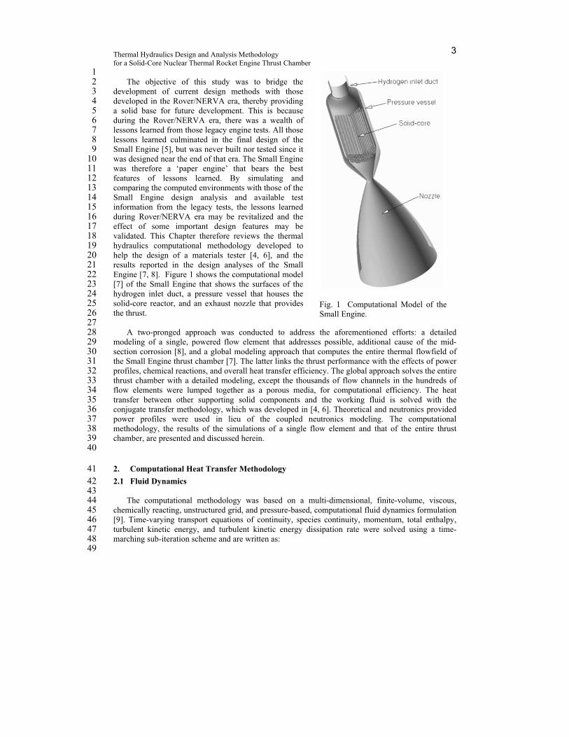
development of current design methods with those 3 developed in the Rover/NERVA era, thereby providing 4 a solid base for future development. This is because 5 during the Rover/NERVA era, there was a wealth of 6 lessons learned from those legacy engine tests. All those 7 lessons learned culminated in the final design of the 8 Small Engine [5], but was never built nor tested since it 9 was designed near the end of that era. The Small Engine 10 was therefore a ‘paper engine’ that bears the best 11 features of lessons learned. By simulating and 12 comparing the computed environments with those of the 13 Small Engine design analysis and available test 14 information from the legacy tests, the lessons learned 15 during Rover/NERVA era may be revitalized and the 16 effect of some important design features may be 17 validated. This Chapter therefore reviews the thermal 18 hydraulics computational methodology developed to 19 help the design of a materials tester [4, 6], and the 20 results reported in the design analyses of the Small 21 Engine [7, 8]. Figure 1 shows the computational model 22 [7] of the Small Engine that shows the surfaces of the 23 hydrogen inlet duct, a pressure vessel that houses the 24 solid-core reactor, and an exhaust nozzle that provides 25 the thrust. 26
27 A two-pronged approach was conducted to address the aforementioned efforts: a detailed 28
modeling of a single, powered flow element that addresses possible, additional cause of the mid-29 section corrosion [8], and a global modeling approach that computes the entire thermal flowfield of 30 the Small Engine thrust chamber [7]. The latter links the thrust performance with the effects of power 31 profiles, chemical reactions, and overall heat transfer efficiency. The global approach solves the entire 32 thrust chamber with a detailed modeling, except the thousands of flow channels in the hundreds of 33 flow elements were lumped together as a porous media, for computational efficiency. The heat 34 transfer between other supporting solid components and the working fluid is solved with the 35 conjugate transfer methodology, which was developed in [4, 6]. Theoretical and neutronics provided 36 power profiles were used in lieu of the coupled neutronics modeling. The computational 37 methodology, the results of the simulations of a single flow element and that of the entire thrust 38 chamber, are presented and discussed herein. 39
40
2. Computational Heat Transfer Methodology 41 2.1 Fluid Dynamics 42
43 The computational methodology was based on a multi-dimensional, finite-volume, viscous, 44
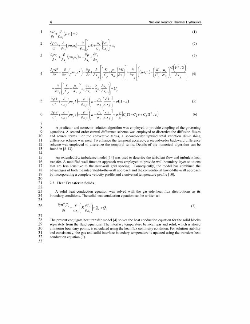
chemically reacting, unstructured grid, and pressure-based, computational fluid dynamics formulation 45 [9]. Time-varying transport equations of continuity, species continuity, momentum, total enthalpy, 46 turbulent kinetic energy, and turbulent kinetic energy dissipation rate were solved using a time-47 marching sub-iteration scheme and are written as: 48
49
Fig. 1 Computational Model of the Small Engine.
Nuclear Reactor Thermal Hydraulics 4
t
x j
uj 0 (1) 1
i
t x j
uji x j
D t
i
x j
i
(2) 2
j
ij
iij
j
i
xx
puu
xt
u
(3) 3
rQ
x
uu
x
uu
C
K
x
jx
V
C
K
jx
jx
H
C
K
jxt
pH
ju
jxt
H
k
kj
k
jk
H
t
pj
H
t
pt
H
t
p
3
2
2/2
(4) 4
jk
t
jj
j x
k
xku
xt
k (5) 5
/2
321
CCCkxx
uxt j
t
jj
j
(6) 6
7 A predictor and corrector solution algorithm was employed to provide coupling of the governing 8
equations. A second-order central-difference scheme was employed to discretize the diffusion fluxes 9 and source terms. For the convective terms, a second-order upwind total variation diminishing 10 difference scheme was used. To enhance the temporal accuracy, a second-order backward difference 11 scheme was employed to discretize the temporal terms. Details of the numerical algorithm can be 12 found in [8-13]. 13
14 An extended k- turbulence model [14] was used to describe the turbulent flow and turbulent heat 15
transfer. A modified wall function approach was employed to provide wall boundary layer solutions 16 that are less sensitive to the near-wall grid spacing. Consequently, the model has combined the 17 advantages of both the integrated-to-the-wall approach and the conventional law-of-the-wall approach 18 by incorporating a complete velocity profile and a universal temperature profile [10]. 19 20 2.2 Heat Transfer in Solids 21 22
A solid heat conduction equation was solved with the gas-side heat flux distributions as its 23 boundary conditions. The solid heat conduction equation can be written as: 24 25
spi
s
j
sp QQx
TK
xt
TC
(7) 26
27 The present conjugate heat transfer model [4] solves the heat conduction equation for the solid blocks 28 separately from the fluid equations. The interface temperature between gas and solid, which is stored 29 at interior boundary points, is calculated using the heat flux continuity condition. For solution stability 30 and consistency, the gas and solid interface boundary temperature is updated using the transient heat 31 conduction equation (7). 32 33
Thermal Hydraulics Design and Analysis Methodology for a Solid-Core Nuclear Thermal Rocket Engine Thrust Chamber
5
2.3 Flow and Heat Transfer in Porous Media 1 2
A two-temperature porosity model was formulated with separate thermal conductivities for the 3 flow and the solid parts. The heat transfer between the flow and solid was modeled by using the 4 empirical correlation of the heat transfer coefficient for circular pipes as a function of flow Reynolds 5 numbers. Empirical multipliers for both the heat transfer and drag loss were determined by comparing 6 solutions of flow passing through a porous flow element with those of a Small Engine 19-channel 7 flow element using detailed conjugate heat transfer modeling [8]. The only affected fluid governing 8 equations are Navier-Stokes and energy equations and can be rewritten as: 9
10 ui
t xj
uj ui p
xi
ij
x j
L
(8) 11
H
t x
ju
jH p
t x
j
K
Cp
t
H
H
xj
x
jt K
Cp
t
H
V 2 / 2 x
j
xj
K
Cp
t
H
uk
uj
xk
2
3uj
uk
xk
Q
r 1
Qs
(9) 12
13 For the solid heat conduction in porous media, 14 15
sCpsTs
t x j
Ks
Ts
xi
1
1Qp Qs (10) 16
17 For the Small Engine 19-channel flow element heat-exchanger configuration, drag loss for flow in 18 circular pipes can be used as a point of departure. That is, 19 20
L 1
2 fL c f U ui / d (11) 21
22 where cf 0.0791Re0.25 is the Blasius formula for turbulent pipe flow [15]. Typical Reynolds 23
numbers in a flow channel range from 10,000 to 40,000. 24 25 For the heat exchange source term, 26 27
Qs 1
2 fq
c f
pr2/3
U Cp Ts T / d (12) 28
29 For the purpose of this study, the conjugate heat transfer module for solids was benchmarked with 30
the analysis of a cylindrical specimen heated by an impinging hot hydrogen jet [4]. The computed 31 solid temperature profiles agreed well with those of a standard solid heat transfer code SINDA [16]. 32 The methodology for flow through porous media was verified through a particle-bed nuclear flow 33 element [17] and the Space Shuttle Main Engine (SSME) main injector assembly [18]. The numerical 34 and physical models for predicting the thrust and wall heat transfer were benchmarked with an 35 analysis of the SSME thrust chamber flowfield, in which the computed axial-thrust performance, flow 36 features, and wall heat fluxes compared well with those of the test data [12]. 37
Nuclear Reactor Thermal Hydraulics 6
1
3. Small Engine 2
3 The goals of this study were achieved by computing the thermal hydraulics of a flow element and 4
the entire thrust chamber of an engine designed near the end of the Rover/NERVA era – the Small 5 Engine. The thrust chamber of Small Engine composes of an inlet plenum, the solid-core nuclear 6 reactor or heat exchanger, and an exhaust nozzle, as shown in Fig. 1. There are 564 flow elements and 7 241 support elements or tie-tubes designed for the thermal nuclear reactor. The flow element is 8 shaped like a hexagonal prism, with a length of about 890 mm and a width of about 19 mm from flat 9 to flat [5, 8]. The prismatic flow element contains 19 tubular coolant channels. Three coolant channel 10 diameters were designed for the Small Engine. Each flow element is held in position by three tie-11 tubes and the corresponding hot-end support system (not modeled). General geometry and operating 12 conditions were obtained from [5], while certain specific operating conditions and nozzle geometry 13 were calculated and provided by the Systems Engineering group. 14
3.1 Power profiles 15 16
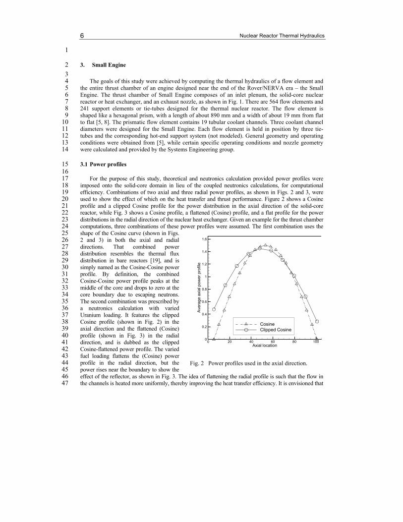
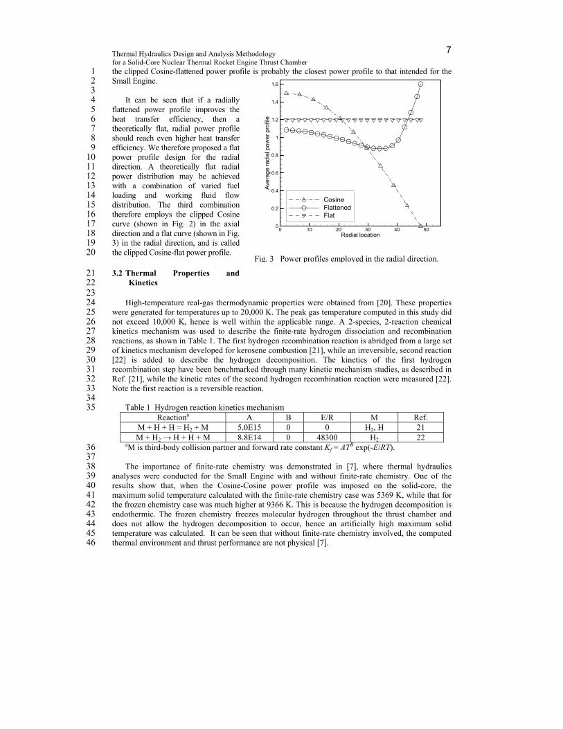
For the purpose of this study, theoretical and neutronics calculation provided power profiles were 17 imposed onto the solid-core domain in lieu of the coupled neutronics calculations, for computational 18 efficiency. Combinations of two axial and three radial power profiles, as shown in Figs. 2 and 3, were 19 used to show the effect of which on the heat transfer and thrust performance. Figure 2 shows a Cosine 20 profile and a clipped Cosine profile for the power distribution in the axial direction of the solid-core 21 reactor, while Fig. 3 shows a Cosine profile, a flattened (Cosine) profile, and a flat profile for the power 22 distributions in the radial direction of the nuclear heat exchanger. Given an example for the thrust chamber 23 computations, three combinations of these power profiles were assumed. The first combination uses the 24 shape of the Cosine curve (shown in Figs. 25 2 and 3) in both the axial and radial 26 directions. That combined power 27 distribution resembles the thermal flux 28 distribution in bare reactors [19], and is 29 simply named as the Cosine-Cosine power 30 profile. By definition, the combined 31 Cosine-Cosine power profile peaks at the 32 middle of the core and drops to zero at the 33 core boundary due to escaping neutrons. 34 The second combination was prescribed by 35 a neutronics calculation with varied 36 Uranium loading. It features the clipped 37 Cosine profile (shown in Fig. 2) in the 38 axial direction and the flattened (Cosine) 39 profile (shown in Fig. 3) in the radial 40 direction, and is dubbed as the clipped 41 Cosine-flattened power profile. The varied 42 fuel loading flattens the (Cosine) power 43 profile in the radial direction, but the 44 power rises near the boundary to show the 45 effect of the reflector, as shown in Fig. 3. The idea of flattening the radial profile is such that the flow in 46 the channels is heated more uniformly, thereby improving the heat transfer efficiency. It is envisioned that 47
Fig. 2 Power profiles used in the axial direction.
Axial location
Ave
rag
eax
ialp
ow
erp
rofil
e
0 20 40 60 80 1000
0.2
0.4
0.6
0.8
1
1.2
1.4
1.6
CosineClipped Cosine
Thermal Hydraulics Design and Analysis Methodology for a Solid-Core Nuclear Thermal Rocket Engine Thrust Chamber
7
the clipped Cosine-flattened power profile is probably the closest power profile to that intended for the 1 Small Engine. 2
3 It can be seen that if a radially 4
flattened power profile improves the 5 heat transfer efficiency, then a 6 theoretically flat, radial power profile 7 should reach even higher heat transfer 8 efficiency. We therefore proposed a flat 9 power profile design for the radial 10 direction. A theoretically flat radial 11 power distribution may be achieved 12 with a combination of varied fuel 13 loading and working fluid flow 14 distribution. The third combination 15 therefore employs the clipped Cosine 16 curve (shown in Fig. 2) in the axial 17 direction and a flat curve (shown in Fig. 18 3) in the radial direction, and is called 19 the clipped Cosine-flat power profile. 20
3.2 Thermal Properties and 21 Kinetics 22
23 High-temperature real-gas thermodynamic properties were obtained from [20]. These properties 24
were generated for temperatures up to 20,000 K. The peak gas temperature computed in this study did 25 not exceed 10,000 K, hence is well within the applicable range. A 2-species, 2-reaction chemical 26 kinetics mechanism was used to describe the finite-rate hydrogen dissociation and recombination 27 reactions, as shown in Table 1. The first hydrogen recombination reaction is abridged from a large set 28 of kinetics mechanism developed for kerosene combustion [21], while an irreversible, second reaction 29 [22] is added to describe the hydrogen decomposition. The kinetics of the first hydrogen 30 recombination step have been benchmarked through many kinetic mechanism studies, as described in 31 Ref. [21], while the kinetic rates of the second hydrogen recombination reaction were measured [22]. 32 Note the first reaction is a reversible reaction. 33
Reactiona A B E/R M Ref. M + H + H = H2 + M 5.0E15 0 0 H2, H 21 M + H2 → H + H + M 8.8E14 0 48300 H2 22
aM is third-body collision partner and forward rate constant Kf = ATB exp(-E/RT). 36 37 The importance of finite-rate chemistry was demonstrated in [7], where thermal hydraulics 38
analyses were conducted for the Small Engine with and without finite-rate chemistry. One of the 39 results show that, when the Cosine-Cosine power profile was imposed on the solid-core, the 40 maximum solid temperature calculated with the finite-rate chemistry case was 5369 K, while that for 41 the frozen chemistry case was much higher at 9366 K. This is because the hydrogen decomposition is 42 endothermic. The frozen chemistry freezes molecular hydrogen throughout the thrust chamber and 43 does not allow the hydrogen decomposition to occur, hence an artificially high maximum solid 44 temperature was calculated. It can be seen that without finite-rate chemistry involved, the computed 45 thermal environment and thrust performance are not physical [7]. 46
Fig. 3 Power profiles employed in the radial direction.
Radial location
Ave
rag
era
dia
lpo
wer
pro
file
0 10 20 30 40 500
0.2
0.4
0.6
0.8
1
1.2
1.4
1.6
CosineFlattenedFlat
Nuclear Reactor Thermal Hydraulics 8
1 The solid-core flow element material is assumed to be the (U, Zr)C-graphite composite A, which 2
was tested as flow element material in a legacy reactor [23]. Properties of thermal conductivity, 3 density, and heat capacity as a function of temperature were obtained for (U, Zr)C-graphite composite 4 A from Ref. [23]. Those properties of Beryllium [19] were used for the reflector and slat in the thrust 5 chamber computation. Slat acts as a buffer between the solid-core and the reflector. The thermal 6 properties for the coating layer deposited on the inner wall of flow channels were also obtained from 7 [23]. 8
4. Small Engine Single Flow Element Modeling 9
10 From the material properties point of view, the main cause of mid-section corrosion was 11
speculated as a mismatch in the thermal expansion of flow element and its coating material [3, 4]. The 12 solution is therefore to improve the material properties through materials development [4, 6]. In 13 addition to the materials development, however, we feel further study through the thermal hydraulics 14 analysis of the fundamental reactor design is also important. That is, reduction of the reactor size 15 often started with reducing the diameter of the flow channels, which results in higher aspect ratio, or 16 longer flow channels. According to the Rayleigh line theory, flow with continuous heat addition in a 17 long tube could choke. When that happens, any further heat addition can only serve to reduce the 18 mass flow rate in the tube or, in other words, to jump to another Rayleigh line of lower mass flow 19 [24]. This phenomenon could cause unintended mass flow mal-distribution in the solid-core reactor, 20 resulting in uneven and high local thermal load in the flow element matrix, thereby cracking the 21 coating material. The goal is therefore to compute if choking could occur in one of the flow channels 22 in the Small Engine. To achieve this goal, the worst case was pursued. That is, the Cosine-Cosine 23 power profile which generates peak thermal load in the center of the reactor was assumed. As a result, the 24 flow element located at the center of the solid-core reactor was selected for the computation. In addition, 25 among the three diameters considered for the flow channel of the Small Engine [5], the smallest flow 26 channel diameter was selected, for its highest aspect ratio. These choices were made such that the 27 computed hot hydrogen flow inside one of the flow channels had the best chance to choke. 28
4.1 Computational Grid Generation 29 30
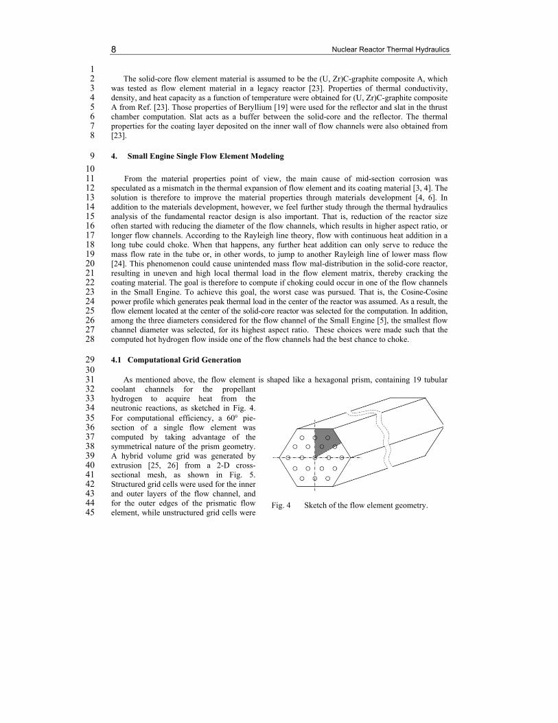
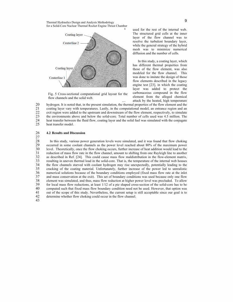
As mentioned above, the flow element is shaped like a hexagonal prism, containing 19 tubular 31 coolant channels for the propellant 32 hydrogen to acquire heat from the 33 neutronic reactions, as sketched in Fig. 4. 34 For computational efficiency, a 60 pie-35 section of a single flow element was 36 computed by taking advantage of the 37 symmetrical nature of the prism geometry. 38 A hybrid volume grid was generated by 39 extrusion [25, 26] from a 2-D cross-40 sectional mesh, as shown in Fig. 5. 41 Structured grid cells were used for the inner 42 and outer layers of the flow channel, and 43 for the outer edges of the prismatic flow 44 element, while unstructured grid cells were 45
Fig. 4 Sketch of the flow element geometry.
Thermal Hydraulics Design and Analysis Methodology for a Solid-Core Nuclear Thermal Rocket Engine Thrust Chamber
9
used for the rest of the internal web. 1 The structured grid cells at the inner 2 layer of the flow channel was to 3 resolve the turbulent boundary layer, 4 while the general strategy of the hybrid 5 mesh was to minimize numerical 6 diffusion and the number of cells. 7 8
In this study, a coating layer, which 9 has different thermal properties from 10 those of the flow element, was also 11 modeled for the flow channel. This 12 was done to imitate the design of those 13 flow elements described in the legacy 14 engine test [23], in which the coating 15 layer was added to protect the 16 carbonaceous compound in the flow 17 element from the alleged chemical 18 attack by the heated, high temperature 19
hydrogen. It is noted that, in the present simulation, the thermal properties of the flow element and the 20 coating layer vary with temperatures. Lastly, in the computational model, an entrance region and an 21 exit region were added to the upstream and downstream of the flow element, respectively, to simulate 22 the environments above and below the solid-core. Total number of cells used was 4.5 million. The 23 heat transfer between the fluid flow, coating layer and the solid fuel was simulated with the conjugate 24 heat transfer model. 25
4.2 Results and Discussion 26 27
In this study, various power generation levels were simulated, and it was found that flow choking 28 occurred in some coolant channels as the power level reached about 80% of the maximum power 29 level. Theoretically, once the flow choking occurs, further increase of heat addition would lead to the 30 reduction of mass flow rate in the flow channel, amount to shifting from one Rayleigh line to another 31 as described in Ref. [24]. This could cause mass flow maldistribution in the flow-element matrix, 32 resulting in uneven thermal load in the solid-core. That is, the temperature of the internal web houses 33 the flow channels starved with coolant hydrogen may rise unexpectedly, potentially leading to the 34 cracking of the coating material. Unfortunately, further increase of the power led to unrealistic 35 numerical solutions because of the boundary conditions employed (fixed mass flow rate at the inlet 36 and mass conservation at the exit). This set of boundary conditions was used because only one flow 37 element was simulated, and thus, mass flow reduction at higher power level was precluded. To allow 38 for local mass flow reductions, at least 1/12 of a pie shaped cross-section of the solid-core has to be 39 computed such that fixed mass flow boundary condition need not be used. However, that option was 40 out of the scope of this study. Nevertheless, the current setup is still acceptable since our goal is to 41 determine whether flow choking could occur in the flow channel. 42 43
Fig. 5 Cross-sectional computational grid layout for the flow channels and the solid web.
Nuclear Reactor Thermal Hydraulics 10
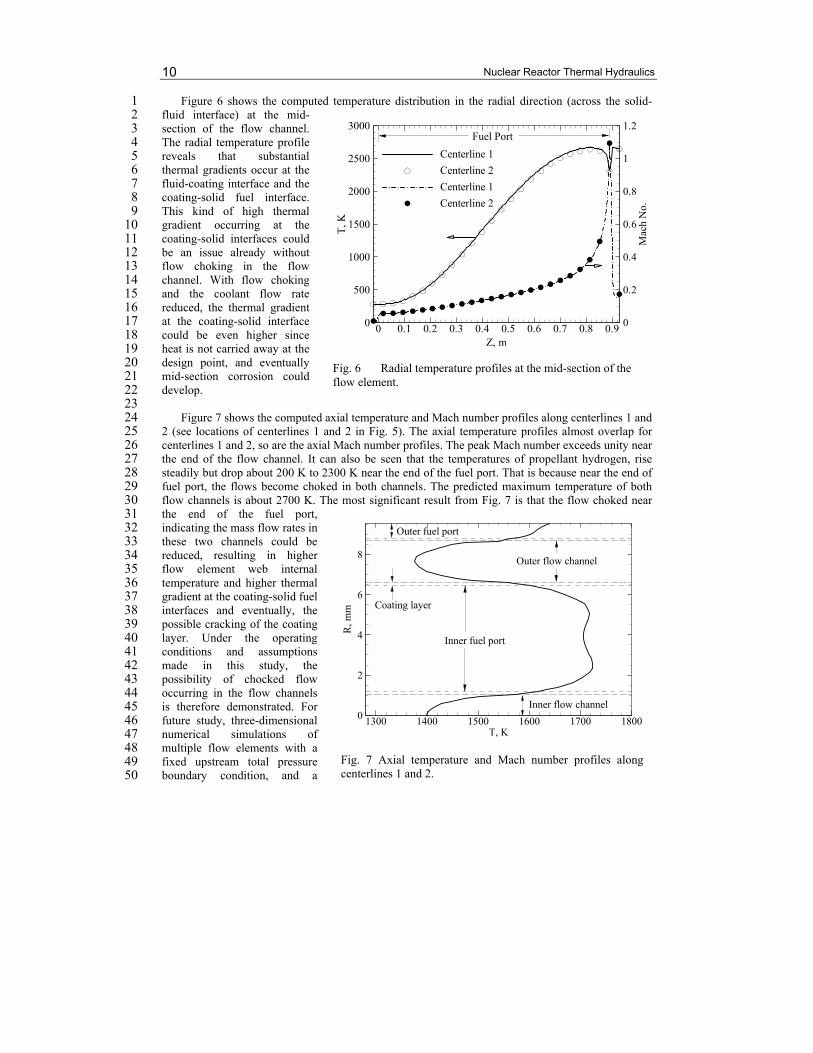
Figure 6 shows the computed temperature distribution in the radial direction (across the solid-1 fluid interface) at the mid-2 section of the flow channel. 3 The radial temperature profile 4 reveals that substantial 5 thermal gradients occur at the 6 fluid-coating interface and the 7 coating-solid fuel interface. 8 This kind of high thermal 9 gradient occurring at the 10 coating-solid interfaces could 11 be an issue already without 12 flow choking in the flow 13 channel. With flow choking 14 and the coolant flow rate 15 reduced, the thermal gradient 16 at the coating-solid interface 17 could be even higher since 18 heat is not carried away at the 19 design point, and eventually 20 mid-section corrosion could 21 develop. 22
23 Figure 7 shows the computed axial temperature and Mach number profiles along centerlines 1 and 24
2 (see locations of centerlines 1 and 2 in Fig. 5). The axial temperature profiles almost overlap for 25 centerlines 1 and 2, so are the axial Mach number profiles. The peak Mach number exceeds unity near 26 the end of the flow channel. It can also be seen that the temperatures of propellant hydrogen, rise 27 steadily but drop about 200 K to 2300 K near the end of the fuel port. That is because near the end of 28 fuel port, the flows become choked in both channels. The predicted maximum temperature of both 29 flow channels is about 2700 K. The most significant result from Fig. 7 is that the flow choked near 30 the end of the fuel port, 31 indicating the mass flow rates in 32 these two channels could be 33 reduced, resulting in higher 34 flow element web internal 35 temperature and higher thermal 36 gradient at the coating-solid fuel 37 interfaces and eventually, the 38 possible cracking of the coating 39 layer. Under the operating 40 conditions and assumptions 41 made in this study, the 42 possibility of chocked flow 43 occurring in the flow channels 44 is therefore demonstrated. For 45 future study, three-dimensional 46 numerical simulations of 47 multiple flow elements with a 48 fixed upstream total pressure 49 boundary condition, and a 50
Fig. 6 Radial temperature profiles at the mid-section of the flow element.
Z, mT
,K
Mac
hN
o.
0 0.1 0.2 0.3 0.4 0.5 0.6 0.7 0.8 0.90
500
1000
1500
2000
2500
3000
0
0.2
0.4
0.6
0.8
1
1.2
Centerline 1
Centerline 2
Centerline 1
Centerline 2
Fuel Port
Fig. 7 Axial temperature and Mach number profiles along centerlines 1 and 2.
T, K
R,m
m
1300 1400 1500 1600 1700 18000
2
4
6
8
Outer fuel port
Coating layer
Inner flow channel
Outer flow channel
Inner fuel port
Thermal Hydraulics Design and Analysis Methodology for a Solid-Core Nuclear Thermal Rocket Engine Thrust Chamber
11
downstream nozzle to remove the fixed exit mass flow boundary condition are necessary to include 1 the inter-element effect. 2
3
5. Small Engine Thrust Chamber Modeling 4
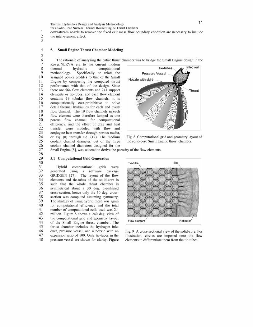
5 The rationale of analyzing the entire thrust chamber was to bridge the Small Engine design in the 6
Rover/NERVA era to the current modern 7 thermal hydraulic computational 8 methodology. Specifically, to relate the 9 assigned power profiles to that of the Small 10 Engine by comparing the computed thrust 11 performance with that of the design. Since 12 there are 564 flow elements and 241 support 13 elements or tie-tubes, and each flow element 14 contains 19 tubular flow channels, it is 15 computationally cost-prohibitive to solve 16 detail thermal hydraulics for each and every 17 flow channel. The 19 flow channels in each 18 flow element were therefore lumped as one 19 porous flow channel for computational 20 efficiency, and the effect of drag and heat 21 transfer were modeled with flow and 22 conjugate heat transfer through porous media, 23 or Eq. (8) through Eq. (12). The medium 24 coolant channel diameter, out of the three 25 coolant channel diameters designed for the 26 Small Engine [5], was selected to derive the porosity of the flow elements. 27
28 5.1 Computational Grid Generation 29
30 Hybrid computational grids were 31
generated using a software package 32 GRIDGEN [27]. The layout of the flow 33 elements and tie-tubes of the solid-core is 34 such that the whole thrust chamber is 35 symmetrical about a 30 deg. pie-shaped 36 cross-section, hence only the 30 deg. cross-37 section was computed assuming symmetry. 38 The strategy of using hybrid mesh was again 39 for computational efficiency and the total 40 number of computational cells used was 2.4 41 million. Figure 8 shows a 240 deg. view of 42 the computational grid and geometry layout 43 of the Small Engine thrust chamber. The 44 thrust chamber includes the hydrogen inlet 45 duct, pressure vessel, and a nozzle with an 46 expansion ratio of 100. Only tie-tubes in the 47 pressure vessel are shown for clarity. Figure 48
Fig. 8 Computational grid and geometry layout of the solid-core Small Engine thrust chamber.
Inlet wallTie-tubes
Pressure Vessel
Nozzle with skirt
Throat
Fig. 9 A cross-sectional view of the solid-core. For illustration, circles are imposed onto the flow elements to differentiate them from the tie-tubes.
Nuclear Reactor Thermal Hydraulics 12
9 shows a cross-sectional view of the solid-core computational grid, depicting flow elements, tie-1 tubes, slat, and reflector. 2 3
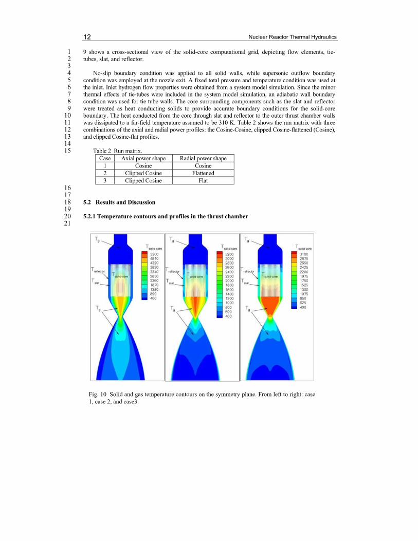
No-slip boundary condition was applied to all solid walls, while supersonic outflow boundary 4 condition was employed at the nozzle exit. A fixed total pressure and temperature condition was used at 5 the inlet. Inlet hydrogen flow properties were obtained from a system model simulation. Since the minor 6 thermal effects of tie-tubes were included in the system model simulation, an adiabatic wall boundary 7 condition was used for tie-tube walls. The core surrounding components such as the slat and reflector 8 were treated as heat conducting solids to provide accurate boundary conditions for the solid-core 9 boundary. The heat conducted from the core through slat and reflector to the outer thrust chamber walls 10 was dissipated to a far-field temperature assumed to be 310 K. Table 2 shows the run matrix with three 11 combinations of the axial and radial power profiles: the Cosine-Cosine, clipped Cosine-flattened (Cosine), 12 and clipped Cosine-flat profiles. 13
14 Table 2 Run matrix. 15
Case Axial power shape Radial power shape 1 Cosine Cosine 2 Clipped Cosine Flattened 3 Clipped Cosine Flat
16 17
5.2 Results and Discussion 18 19
5.2.1 Temperature contours and profiles in the thrust chamber 20 21
Fig. 10 Solid and gas temperature contours on the symmetry plane. From left to right: case 1, case 2, and case3.
Thermal Hydraulics Design and Analysis Methodology for a Solid-Core Nuclear Thermal Rocket Engine Thrust Chamber
13
Figure 10 shows the computed thrust chamber temperature contours with three different power 1 profiles: the Cosine-Cosine, clipped Cosine-flattened, and clipped Cosine-flat profiles. In the plotted 2 temperature contours, those in the solid-core represent the solid temperatures in the flow elements; 3 the portions surrounding the solid-core depict the temperatures in the slat and reflector, while the rest 4 are the gas temperature contours. It can be seen that the solid-core temperature contours on the left 5 (case 1) reflect the effect of Cosine-Cosine power distribution, since the peak temperature is located 6 near the middle of the reactor, except it is shifted downstream of the geometrical center in the axial 7 direction. The hydrogen gas temperature contours in the solid core (not shown) take the same shape 8 as those of the solid temperature, except lower. The heat transfer delay in the axial direction is a result 9 of the energy balance between the cooling from the incoming cold hydrogen in the flow channels and 10 the heating from the nuclear material in the web of the flow elements. It is apparent that the effect of 11 cold hydrogen won the fight between the two counter-acting phenomena, and pushes the peak flow 12 element temperature downstream that shows up as a delay in heat transfer. 13 14
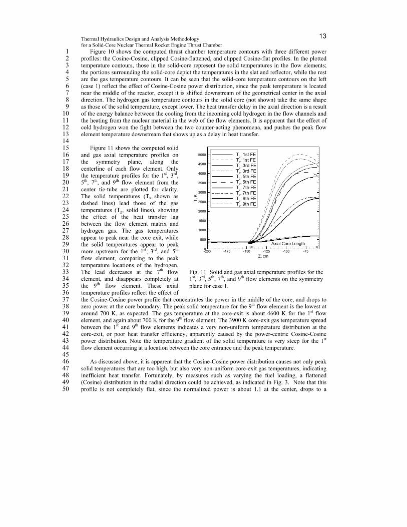
Figure 11 shows the computed solid 15 and gas axial temperature profiles on 16 the symmetry plane, along the 17 centerline of each flow element. Only 18 the temperature profiles for the 1st, 3rd, 19 5th, 7th, and 9th flow element from the 20 center tie-tube are plotted for clarity. 21 The solid temperatures (Ts shown as 22 dashed lines) lead those of the gas 23 temperatures (Tg, solid lines), showing 24 the effect of the heat transfer lag 25 between the flow element matrix and 26 hydrogen gas. The gas temperatures 27 appear to peak near the core exit, while 28 the solid temperatures appear to peak 29 more upstream for the 1st, 3rd, and 5th 30 flow element, comparing to the peak 31 temperature locations of the hydrogen. 32 The lead decreases at the 7th flow 33 element, and disappears completely at 34 the 9th flow element. These axial 35 temperature profiles reflect the effect of 36 the Cosine-Cosine power profile that concentrates the power in the middle of the core, and drops to 37 zero power at the core boundary. The peak solid temperature for the 9th flow element is the lowest at 38 around 700 K, as expected. The gas temperature at the core-exit is about 4600 K for the 1st flow 39 element, and again about 700 K for the 9th flow element. The 3900 K core-exit gas temperature spread 40 between the 1st and 9th flow elements indicates a very non-uniform temperature distribution at the 41 core-exit, or poor heat transfer efficiency, apparently caused by the power-centric Cosine-Cosine 42 power distribution. Note the temperature gradient of the solid temperature is very steep for the 1st 43 flow element occurring at a location between the core entrance and the peak temperature. 44
45 As discussed above, it is apparent that the Cosine-Cosine power distribution causes not only peak 46
solid temperatures that are too high, but also very non-uniform core-exit gas temperatures, indicating 47 inefficient heat transfer. Fortunately, by measures such as varying the fuel loading, a flattened 48 (Cosine) distribution in the radial direction could be achieved, as indicated in Fig. 3. Note that this 49 profile is not completely flat, since the normalized power is about 1.1 at the center, drops to a 50
Fig. 11 Solid and gas axial temperature profiles for the 1st, 3rd, 5th, 7th, and 9th flow elements on the symmetry plane for case 1.
minimum of about 0.9 at two-thirds of the radius outward, then rise to a maximum power of 1.6 at the 1 boundary. But comparing it to the Cosine-Cosine power profile, it is relatively flat. In fact, by our 2 estimation, this clipped Cosine–flattened 3 power profile is the most representative 4 of that intended for the Small Engine. 5 The middle picture of Fig. 10 shows the 6 computed solid and gas temperatures, 7 for this clipped Cosine-flattened power 8 profile. It can be seen that the solid and 9 gas temperature contours, reflect the 10 effect of the clipped Cosine-flattened 11 power distribution. Comparing to the 12 temperature contours in the left of Fig. 13 10, those in the middle are more 14 uniform. The peak solid and gas 15 temperatures in the middle of Fig. 10 at 16 about 3149 and 3081 K., respectively, 17 are much lower than those in the left of 18 Fig. 10, or 5369 and 4596 K., 19 respectively. 20
21 Figure 12 shows the computed solid 22
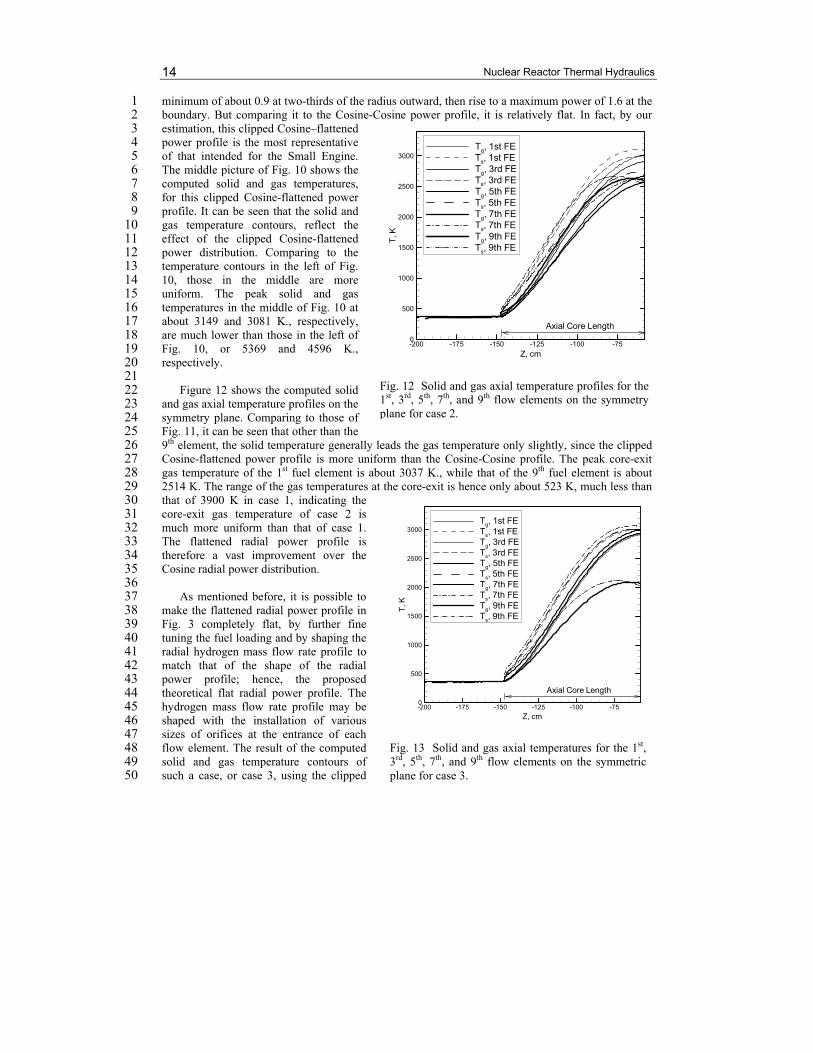
and gas axial temperature profiles on the 23 symmetry plane. Comparing to those of 24 Fig. 11, it can be seen that other than the 25 9th element, the solid temperature generally leads the gas temperature only slightly, since the clipped 26 Cosine-flattened power profile is more uniform than the Cosine-Cosine profile. The peak core-exit 27 gas temperature of the 1st fuel element is about 3037 K., while that of the 9th fuel element is about 28 2514 K. The range of the gas temperatures at the core-exit is hence only about 523 K, much less than 29 that of 3900 K in case 1, indicating the 30 core-exit gas temperature of case 2 is 31 much more uniform than that of case 1. 32 The flattened radial power profile is 33 therefore a vast improvement over the 34 Cosine radial power distribution. 35 36
As mentioned before, it is possible to 37 make the flattened radial power profile in 38 Fig. 3 completely flat, by further fine 39 tuning the fuel loading and by shaping the 40 radial hydrogen mass flow rate profile to 41 match that of the shape of the radial 42 power profile; hence, the proposed 43 theoretical flat radial power profile. The 44 hydrogen mass flow rate profile may be 45 shaped with the installation of various 46 sizes of orifices at the entrance of each 47 flow element. The result of the computed 48 solid and gas temperature contours of 49 such a case, or case 3, using the clipped 50
Fig. 12 Solid and gas axial temperature profiles for the 1st, 3rd, 5th, 7th, and 9th flow elements on the symmetry plane for case 2.
Thermal Hydraulics Design and Analysis Methodology for a Solid-Core Nuclear Thermal Rocket Engine Thrust Chamber
15
Cosine-flat power profile, is shown in the right of Fig. 10. It can be seen in terms of the solid-core 1 radial temperature distribution and the uniformity of the gas temperature beneath the solid core, this 2 result is the most uniform. Figure 13 shows the solid and gas axial temperature profiles for the 1st, 3rd, 3 5th, 7th, and 9th flow elements in the solid-core for case 3. It can be seen that the temperature spread 4 among the 1st, 3rd, 5th and 7th flow elements are much smaller than those of earlier cases, except those 5 of the 9th flow element due to the heat loss to the slat and reflector. From the right picture of Fig. 10 6 and from Fig. 13, it can be seen this flat radial power profile is a very good power profile in terms of 7 general uniformity of the temperatures for both solid and gas temperatures inside the core and for gas 8 exit temperatures. 9 10 5.2.2 Hydrogen atom mass fraction contours in the thrust chamber 11
12 Figure 14 shows the computed thrust chamber hydrogen mass fraction contours with three 13
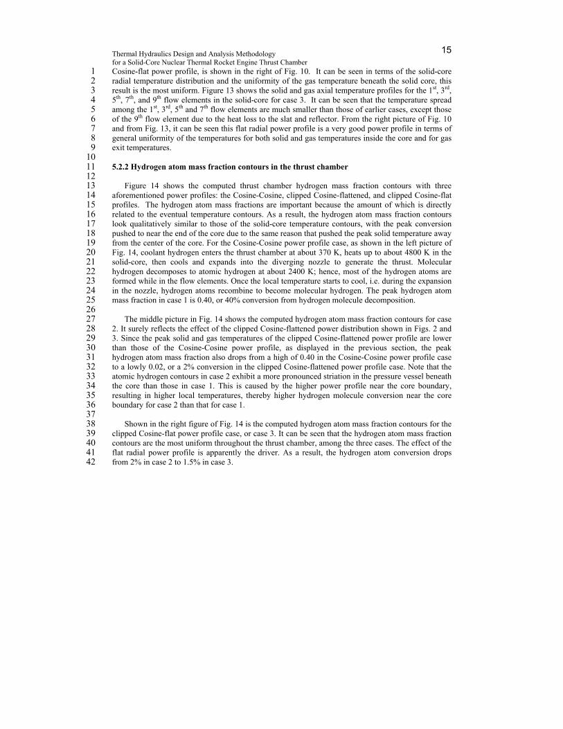
aforementioned power profiles: the Cosine-Cosine, clipped Cosine-flattened, and clipped Cosine-flat 14 profiles. The hydrogen atom mass fractions are important because the amount of which is directly 15 related to the eventual temperature contours. As a result, the hydrogen atom mass fraction contours 16 look qualitatively similar to those of the solid-core temperature contours, with the peak conversion 17 pushed to near the end of the core due to the same reason that pushed the peak solid temperature away 18 from the center of the core. For the Cosine-Cosine power profile case, as shown in the left picture of 19 Fig. 14, coolant hydrogen enters the thrust chamber at about 370 K, heats up to about 4800 K in the 20 solid-core, then cools and expands into the diverging nozzle to generate the thrust. Molecular 21 hydrogen decomposes to atomic hydrogen at about 2400 K; hence, most of the hydrogen atoms are 22 formed while in the flow elements. Once the local temperature starts to cool, i.e. during the expansion 23 in the nozzle, hydrogen atoms recombine to become molecular hydrogen. The peak hydrogen atom 24 mass fraction in case 1 is 0.40, or 40% conversion from hydrogen molecule decomposition. 25
26 The middle picture in Fig. 14 shows the computed hydrogen atom mass fraction contours for case 27
2. It surely reflects the effect of the clipped Cosine-flattened power distribution shown in Figs. 2 and 28 3. Since the peak solid and gas temperatures of the clipped Cosine-flattened power profile are lower 29 than those of the Cosine-Cosine power profile, as displayed in the previous section, the peak 30 hydrogen atom mass fraction also drops from a high of 0.40 in the Cosine-Cosine power profile case 31 to a lowly 0.02, or a 2% conversion in the clipped Cosine-flattened power profile case. Note that the 32 atomic hydrogen contours in case 2 exhibit a more pronounced striation in the pressure vessel beneath 33 the core than those in case 1. This is caused by the higher power profile near the core boundary, 34 resulting in higher local temperatures, thereby higher hydrogen molecule conversion near the core 35 boundary for case 2 than that for case 1. 36
37 Shown in the right figure of Fig. 14 is the computed hydrogen atom mass fraction contours for the 38
clipped Cosine-flat power profile case, or case 3. It can be seen that the hydrogen atom mass fraction 39 contours are the most uniform throughout the thrust chamber, among the three cases. The effect of the 40 flat radial power profile is apparently the driver. As a result, the hydrogen atom conversion drops 41 from 2% in case 2 to 1.5% in case 3. 42
Nuclear Reactor Thermal Hydraulics 16
1 5.2.3 Summary 2
3 The computed heat transfer and thrust performance design parameters for all three cases are 4
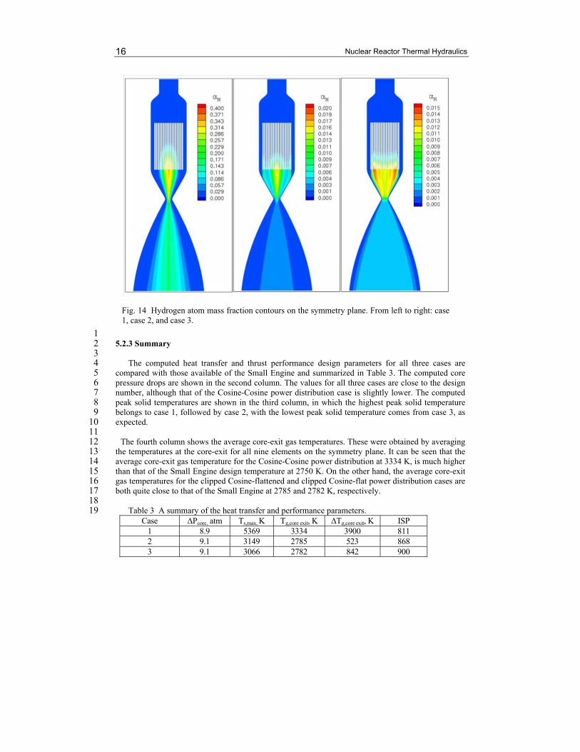
compared with those available of the Small Engine and summarized in Table 3. The computed core 5 pressure drops are shown in the second column. The values for all three cases are close to the design 6 number, although that of the Cosine-Cosine power distribution case is slightly lower. The computed 7 peak solid temperatures are shown in the third column, in which the highest peak solid temperature 8 belongs to case 1, followed by case 2, with the lowest peak solid temperature comes from case 3, as 9 expected. 10 11
The fourth column shows the average core-exit gas temperatures. These were obtained by averaging 12 the temperatures at the core-exit for all nine elements on the symmetry plane. It can be seen that the 13 average core-exit gas temperature for the Cosine-Cosine power distribution at 3334 K, is much higher 14 than that of the Small Engine design temperature at 2750 K. On the other hand, the average core-exit 15 gas temperatures for the clipped Cosine-flattened and clipped Cosine-flat power distribution cases are 16 both quite close to that of the Small Engine at 2785 and 2782 K, respectively. 17 18 Table 3 A summary of the heat transfer and performance parameters. 19
Case ΔPcore, atm Ts,max, K Tg,core exit, K ΔTg,core exit, K ISP 1 8.9 5369 3334 3900 811 2 9.1 3149 2785 523 868 3 9.1 3066 2782 842 900
Fig. 14 Hydrogen atom mass fraction contours on the symmetry plane. From left to right: case 1, case 2, and case 3.
Thermal Hydraulics Design and Analysis Methodology for a Solid-Core Nuclear Thermal Rocket Engine Thrust Chamber
17
Small Engine 9.0 - 2750 - 860~875 1
The computed temperature spread, or the difference of the core-exit gas temperature between the 2 first and the 9th flow elements, is shown in the fifth column. Lower temperature spread represents 3 more uniform temperature distribution amongst the flow elements, or better heat transfer efficiency. It 4 can be seen that the clipped Cosine-flattened power profile produces best heat transfer efficiency, the 5 clipped Cosine-flat power profile ranks the second, while the Cosine-Cosine power profile has the 6 worst heat transfer efficiency. Note that if without the outlier of the temperature profile at the 9th fuel 7 element for case 3, its temperature spread from the rest is more uniform than that of case 2, as 8 indicated in Figs. 12 and 13. 9
10 From the last column comes with the comparison of the specific impulses. The best thrust 11
performance belongs to case 3 that is much higher than the design value, followed by case2 which is 12 within the design range, while case 1 has the lowest ISP. Yet the maximum atomic hydrogen 13 conversions are 40%, 2% and 1.5%, for cases 1, 2, and 3, respectively. These results demonstrate that 14 the notion of higher temperature, more atomic hydrogen, therefore higher thrust is not valid. Rather, it 15 is the most uniform radial power profile that produces the highest thrust. 16
17 In summary, the computed core pressure drop, core-exit gas temperature, and specific impulse, 18
from the clipped Cosine-flattened power distribution agree well with those of the Small Engine. The 19 result indicates the fluid, thermal, and hydrogen environments computed with the present 20 computational thermal hydraulics methodology closely emulate what was intended for the original 21 Small Engine design. In addition, examining the results of our proposed clipped Cosine-flat power 22 distribution, not only the computed core-exit gas temperature and core pressure drop agree equally 23 well with those of the Small Engine, the computed specific impulse is 25 to 40 seconds higher than 24 those of the Small Engine, demonstrating the present computational methodology can be used to 25 guide the future design. 26
27
6. Conclusion 28 Thermal hydraulics computational design analyses were performed to investigate the mid-section 29
corrosion issue occurred during the legacy engine tests, and to predict the heat transfer efficiency and 30 thrust performance for a virtual solid-core, nuclear thermal engine thrust chamber – the Small Engine. 31 Multiphysics invoked include the turbulent flow and heat transfer, finite-rate chemistry, power 32 generation, and conjugate heat transfer for solids and porous media. The results of a detailed single 33 flow element modeling show that under the assumption of the worst design condition, the hot 34 hydrogen flow could choke near the end of the narrow, long flow channels, which could lead to 35 hydrogen flow reduction and local hot spots in the solid-core; hence, originating the mid-section 36 corrosion. In addition, a unified Small Engine thrust chamber thermal flow field constituting those of 37 the inlet plenum, the pressure vessel, and the nozzle, was analyzed with three power profiles. It was 38 found that the computed core pressure drop, core-exit gas temperature, and specific impulse for the 39 clipped Cosine-flattened power profile closely agreed with those of the Small Engine design values. It 40 was also found that with our proposed clipped Cosine-flat power profile, not only the computed core-41 ext gas temperature and core pressure drop closely agreed with those of the Small Engine, the 42 corresponding specific impulse was much higher than those of the original Small Engine numbers. 43 The design lesson learned from this effort is that high hydrogen molecule dissociation to hydrogen 44 atoms neither improves the heat transfer efficiency, nor increases the thrust performance. Rather, it is 45 the more uniform radial power profile that produces lower peak solid temperature, higher heat 46 transfer efficiency, and higher thrust performance. 47
Nuclear Reactor Thermal Hydraulics 18
7. Nomenclature 1 2 A = pre-exponential rate constant 3 B = temperature power dependence 4 C1,C2,C3,C= turbulence modeling constants, 1.15, 1.9, 0.25, and 0.09 5 Cp = heat capacity 6 D = diffusivity 7 d = flow channel diameter 8 E = activation energy 9 fL, fq = empirical multipliers 10 H = total enthalpy 11 K = thermal conductivity 12 k = turbulent kinetic energy 13 L = drag loss due to porous media 14 P = pressure 15 pr = Prandtl number 16 Q = volumetric heat source 17 R = radial distance 18 R = gas constant 19 Re = Reynolds number 20 T = temperature 21 t = time, s 22 U = flow speed 23 ui = mean velocities in three directions 24 x = Cartesian coordinates 25 Z = axial distance 26 = species mass fraction 27 = porosity or void of fraction 28 ε = turbulent kinetic energy dissipation rate 29 μ = viscosity 30 μt = turbulent eddy viscosity (= C k
2/) 31 Π = turbulent kinetic energy production 32 ρ = density 33 = turbulence modeling constants 34 τ = shear stress 35 ω = chemical species production rate 36 37 Subscripts and superscripts 38 cl = centerline 39 p = nuclear power source 40 r = radiation 41 s = surface, solid, or porous media 42 t = turbulent flow 43 44
8. Acknowledgments 45 46
This study was partially supported by a Nuclear Systems Office task entitled “Multiphysics 47 Thrust Chamber Modeling” with funding from the Prometheus Power and Propulsion Office, NASA 48
Thermal Hydraulics Design and Analysis Methodology for a Solid-Core Nuclear Thermal Rocket Engine Thrust Chamber
19
Headquarter. Ron Porter was the Marshall Space Flight Center Nuclear Systems Office Manager. 1 Wayne Bordelon was the Nuclear Thermal Propulsion manager. Michael Houts was the Nuclear 2 Research Manager. Steve Simpson and Karl Nelson provided the clipped Cosine-flattened power 3 profile, nozzle geometry and system modeling results. Bill Emrich suggested the Cosine-Cosine 4 power profile. Solid material thermal properties provided by Panda Binayak, Robert Hickman, and 5 Bill Emrich are also acknowledged. 6
9. References 7 8 [1] Bordelon, W.J., Ballard, R.O., and Gerrish, Jr., H.P., “A Programmatic and Engineering Approach 9 to the Development of a Nuclear Thermal Rocket for Space Exploration,” AIAA Paper 2006-5082, 10 July 2006. 11 [2] Howe, S.D., “Identification of Archived Design Information for Small Class Nuclear Rockets,” 12 AIAA Paper 2005-3762, 41st AIAA/ASME/SAE/ASEE Joint Propulsion Conference, Tucson, 13 Arizona, 2005.. 14 [3] Emrich, W.J., Jr., “Non-Nuclear NTR Environment Simulator,” Space Technology and 15 Applications International Forum (STAIF-2006), Albuquerque, NM, Feb. 12-16, 2006, American 16 Institute of Physics Proceedings, edited by El-Genk, M.S., Melville, N.Y., Vol. 813, 2006, pp. 531-17 536. 18 [4] Wang, T.-S., Luong, V., Foote, J., Litchford, R., and Chen, Y.-S., “Analysis of a Cylindrical 19 Specimen Heated by an Impinging Hot Hydrogen Jet,” Journal of Thermophysics and Heat Transfer, 20 Vol. 24, No. 2, April-June, 2010, pp. 381~387. doi: 10.2514/1.47737. 21 [5] Durham, F.P., “Nuclear Engine Definition Study”, Preliminary Report, Vol. 1 – Engine 22 Description, LA-5044-MS, Los Alamos Scientific Laboratory, Los Alamos, New Mexico, September 23 1972. 24 [6] Wang, T.-S., Foote, J., and Litchford, R., “Multiphysics Thermal-Fluid Design Analysis of a Non-25 Nuclear Tester for Hot-Hydrogen Material Development,” Space Technology and Applications 26 International Forum (STAIF-2006), Albuquerque, NM, Fe. 12-16, 2006, American Institute of 27 Physics Proceedings, edited by El-Genk, M.S., Melville, N.Y., Vol. 813, 2006, pp. 537-544. 28 [7] Wang, T.-S., Canabal, F., Chen, Y.-S., Cheng, Gary, “Multiphysics Computational Analysis of a 29 Solid-Core Nuclear Thermal Engine Thrust Chamber,” Journal of Propulsion and Power, Vol. 26, 30 No. 3, May-June, 2010, pp. 407~414. doi: 10.2514/1.47759. 31 [8] Cheng, G., Ito, Y., Ross, D., Chen, Y.-S., and Wang, T.-S., “Numerical Simulations of Single 32 Flow Element in a Nuclear Thermal Thrust Chamber,” AIAA Paper 2007-4143, 39th AIAA 33 Thermophysics Conference, Miami, FL, 2007. 34 [9] Shang, H.M., and Chen, Y.-S., “Unstructured Adaptive Grid method for Reacting Flow 35 Computation,” AIAA Paper 1997-3183, Seattle, WA (1997). 36 [10] Wang, T.-S., Droege, A., D’Agostino, M., Lee, Y.-C., and Williams, R., “Asymmetric Base-37 Bleed Effect on Aerospike Plume-Induced Base-Heating Environment,” Journal of Propulsion and 38 Power, Vol. 20, No. 3, 2004, pp. 385-393. 39 [11] Wang, T.-S., Chen, Y.-S., Liu, J., Myrabo, L.N., and Mead, F.B. Jr., “Advanced Performance 40 Modeling of Experimental Laser Lightcraft,” Journal of Propulsion and Power, Vol. 18, No. 6, 2002, 41 pp. 1129-1138. 42 [12] Wang, T.-S., “Multidimensional Unstructured-Grid Liquid Rocket Engine Nozzle Performance 43 and Heat Transfer Analysis,” Journal of Propulsion and Power, Vol. 22, No. 1, 2006, pp. 78-84. 44 [13] Wang, T.-S., “Transient Three-Dimensional Startup Side Load Analysis of a Regeneratively 45 Cooled Nozzle,” Shock Waves – An International Journal on Shock Waves, Detonations and 46 Explosions. Vol. 19, Issue 3, 2009, pp. 251~264. DOI: 10.1007/s00193-009-0201-2. 47
Nuclear Reactor Thermal Hydraulics 20
[14] Chen, Y.-S., and Kim, S. W., “Computation of Turbulent Flows Using an Extended k- 1 Turbulence Closure Model,” NASA CR-179204, 1987. 2 [15] Bird, R.B., Stewart, W.E., Lightfoot, E.N., “Transport Phenomena,” 1960. 3 [16] Gaski, J., “The Systems Improved Numerical Differencing Analyzer (SINDA) Code – a User’s 4 Manual,” Aerospace Corp., El Segundo, CA, Feb. 1986. 5 [17] Wang, T.-S. and Schutzenhofer, L. A., "Numerical Analysis of a Nuclear Fuel Element for 6 Nuclear Thermal Propulsion," AIAA Paper 91-3576, September, 1991. 7 [18] Cheng, G.-C., Chen, Y.-S., and Wang, T.-S., "Flow Distribution Around the SSME Main 8 Injector Assembly Using Porosity Formulation," AIAA Paper 95-0350, January, 1995. 9 [19] Glasstone, S., and Edlund, M.C., “The Elements of Nuclear Reactor Theory,” D. Van Nostrand 10 Company, Inc., Tornoto, Canada, 1958. 11 [20] McBride, B.J., Zehe, M.J., and Gordon, S., “NASA Glenn Coefficients for Calculating 12 Thermodynamic Properties of Individual Species,” NASA TP-2002-211556, Glenn Research Center, 13 Cleveland, Ohio. September, 2002. 14 [21] Wang, T.-S., “Thermophysics Characterization of Kerosene Combustion,” Journal of 15 Thermophysics and Heat Transfer, Vol. 15, No. 2, 2001, pp. 140-147. 16 [22] Baulch, D.L., Drysdale, D.D., Horne, D.G., and LLoyd, A.C., "Evaluated Kinetic Data for High 17 temperature Reactions", Vol. 1, The Chemical Rubber Company, Cleveland, Ohio, 1972. 18 [23] Lyon, L. L., “Performance of (U, Zr)C-Graphite (Composite) and of (U, Zr)C (Carbide) Fuel 19 Elements in the Nuclear Furnace 1 Test Reactor,” LA-5398-MS, Los Alamos Scientific Laboratory, 20 Los Alamos, New Mexico, 1973. 21 [24] James, E.A., J., “Gas Dynamics”, Allyn and Bacon, Inc., Boston, Mass., 1969. 22 [25] Ito, Y., and Nakahashi, K., “Direct Surface Triangulation Using Stereolithography Data,” AIAA 23 Journal, Vol. 40, No. 3, 2002, pp. 490-496. DOI: 10.2514/2.1672. 24 [26] Ito, Y., and Nakahashi, K., “Surface Triangulation for Polygonal Models Based on CAD Data,” 25 International Journal for Numerical Methods in Fluids, Vol. 39, Issue 1, 2002, pp. 75-96. DOI: 26 10.1002/fld.281. 27 [27] Steinbrenner, J.P., Chawner, J.R., and Fouts, C., “Multiple Block Grid Generation in the 28 interactive Environment,” AIAA Paper 90-1602, June 1990. 29