Vapor-water two phase flow separation in pressure vessel of nuclear power plants is accomplished with swirl motion using vanes. In order to reduce separation pressure loss and to make it economic, a new type of low cost simplified in- novative separator using lattice core configuration is proposed where swirling is caused by the orthogonal driving flow. The performance of the separator has been assessed numerically with the commercial CFD code FLUENT 14.0. The numerical analysis is compared with the experiment. The geometry and flow conditions are chosen according to the experiment. In the analysis, standard k − and realizable k − turbulence models are implemented. The prediction of maximum air void fraction with realizable k − model was almost the same as input air void fraction but the void frac- tion computed by standard k − model was compared better with the experimental results than the realizable k − model. Some discrepancies in flow pattern between the experimental and simulation results are observed which might be due to the difference of nozzle shape. However, a more detailed model is necessary to arrive at the final conclusion. Keywords: Two Phase Flow; Separation; Nuclear Power Plants; Swirling; CFD
1. Introduction
Boiling water reactors (BWRs) are equipped with steam separators for splitting a two-phase mixture into steam and water before feeding the steam to dryers and turbines [1]. Steam separators are used to remove water from steam in a BWR. In the separator, a two phase flow of steam-water mixture rises through the stand pipes to strike vanes which give the mixture a swirl, forming a vortex where centrifugal forces form a vortex and where centrifugal forces separate the water from the steam in the barrel. An annular two phase dispersed flow is oc- curred there. The steam including the water droplets, leave the separator at the top and goes into the dryers. The separated water rises long the inside wall of the bar- rels, flows through pick-off rings, and exits from the discharge passages through the pick off rings. When up- grading the power density of BWR core, one of the tech- nical issues we have to deal with is the improvement of the steam separators. Since the upgrading causes the in-
crease in the steam quality and the flow velocity at the entrance of the steam separator. In the two phase flow regions pressure drop may increase what results in the deterioration of flow stability which is often seen in the conventional separator. Therefore, the steam separator should be improved so as to decrease the pressure drop at high steam qualities without degrading the separator performance.
Hirai and Yokobori have proposed a new two phase flow separation system using swirling fluidics [2]. Util- izing square arrangement of BWR fuel assemblies, two- phase separation is achieved by adding the artificial ra- dial flow divided partially from total axial core flow. The most important characteristic feature is the removal of stationary vane, which is replaced by the fluidics. This concept is applied in the degassing machine in the smoking room. They clarified the thermal-hydraulic be- haviors of this swirl motion using small mock-up appa- ratus. Both water and air were used as atmospheric two- phase flow and experiment small-scale test facility was fabricated [3]. They confirmed through the visualizing *Corresponding author.
experiments that the two-phase flow separation was well confirmed along the flow distribution. From the laser sheet plane normal to the main flow direction, four mini scale jets were well mixed and large-scale swirling flow motion was found to be successfully created. Throughout the tests, important parameters such as flow rate, angle, the sub and main flow ratio, void fraction and sub flow axial position were varied. According to these parameter sensitivities, separated behaviors were so stable that two-phase flow was well separated in every test case.
Control rod
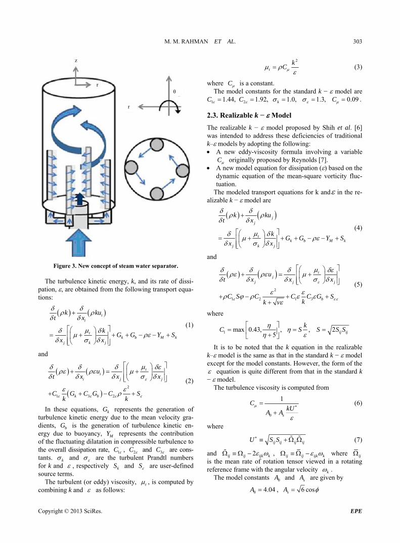
These performances have been estimated in such mock-up tests, however, such tests are of long duration and costly. Therefore, it would be better to develop a numerical method to estimate separator performances so as to develop an innovative separator. In the present study, an idea of low cost simplified innovative separator using lattice core configuration is proposed where swirl- ing is caused by the orthogonal driving flow. The four fuel assemblies around the control rod of BWR, the con- ventional separator with swirler and the proposed con- cept of the separator are shown in Figures 1-3, respec- tively. But the performance of the separator is still needed to be assed. Hence, the objective of the present study is to develop a numerical model to estimate the performance of the proposed separator and to validate the developed model with the experimental results. A three dimensional analysis of steam-water separation has been performed with the commercial numerical analysis code ANSYS FLUENT 14.0 which consists of a three-dimen- sional two-fluid model [4]. In the analysis, the geometry and flow conditions are chosen according to the experi- mental study of Hirai [3] who studied experimentally the performance of the vapor-water separation of the pro- posed model.
Fuel
2. Steam Water Separation by ANSYS FLUENT 14.0
2.1. Numerical Models
The computational fluid dynamic code, FLUENT 14.0 was used to investigate the 3-D turbulent flow in the cylinder using the standard k − and the realizable k − turbulence models. In the calculation a phase–coupled SIMPLE (Semi-Implicit Method for Pressure Linked Equations) algorithm for the pressure-velocity coupling is adopted. The second order upwind schemes were used for the momentum while first order upwind schemes were used for the turbulence kinetic energy, turbulence dissipation rate, and volume fraction. Convergence was assumed when the residual of the equations dropped more than three orders of magnitude. The under relaxa- tion parameters for pressure, momentum, volume frac- tion, turbulence kinetic energy and turbulence dissipa- tionrate were selected as 0.3, 0.7, 0.5, 0.8 and 0.8,
Reactor pressure vessel Rod assembly
Figure 1. Four fuel assemblies around the control rod of BWR.
Figure 2. Conventional separator with swirler. respecttively. Since the flow simulation involved the combined effects of turbulence and two phase flow, the standard k − and realizable k − turbulence models are implemented in this study.
2.2. Standard k − Model
The standard k − model [5] is a semi-empirical model based on model transport equations for the turbulence kinetic energy (k) and its dissipation rate ().
The turbulence kinetic energy, k, and its rate of dissi- pation, , are obtained from the following transport equa- tions:
ii
tk b
j k j
k kut x
kG G
x x
M kY S
(1)
and
2
1 3 2
ii j
k b
ut x x
C G C G Ck k
t
jx
S
G
(2)
In these equations, k represents the generation of turbulence kinetic energy due to the mean velocity gra- dients, b is the generation of turbulence kinetic en- ergy due to buoyancy,
G
MY represents the contribution of the fluctuating dilatation in compressible turbulence to the overall dissipation rate, 1C , 2C and 3C are cons- tants. k and are the turbulent Prandtl numbers for k and , respectively and kS S are user-defined source terms.
The turbulent (or eddy) viscosity, t , is computed by combining k and as follows:
2
t
kC (3)
C
where is a constant. The model constants for the standard k − model are
,1 1.44C ,2 1.92C 1.0,k 1.3, 0.09C .
2.3. Realizable k − Model
The realizable k − model proposed by Shih et al. [6] was intended to address these deficiencies of traditional k– models by adopting the following: A new eddy-viscosity formula involving a variable
C originally proposed by Reynolds [7]. A new model equation for dissipation () based on the
dynamic equation of the mean-square vorticity fluc- tuation.
The modeled transport equations for k and in the re-alizable k − model are
jj
tk b M k
j k j
k kut x
kG G Y S
x x
(4)
and
2
1 2 1 3
tj
j j j
b
ut x x x
C S C C C G Skk
(5)
where
1 max 0.43, ,5
C
,
kS 2 ij ijS S S
It is to be noted that the k equation in the realizable k– model is the same as that in the standard k − model except for the model constants. However, the form of the equation is quite different from that in the standard k − model.
The turbulence viscosity is computed from
0
1
s
CkU
A A (6)
where
ij ij ij ijU S S
2
(7)
and ij ij ijk k , ij ij ijk k where ij is the mean rate of rotation tensor viewed in a rotating reference frame with the angular velocity k .
The model constants for the realizable k − model are 2 1.9,C 1 1.44C , k 1.2
2.4. Geometrical Consideration
Figure 4 shows the geometry of the present simulation. The separator has a cylindrical configuration with the diameter of 70 mm and the length of the separator is 300 mm. The fluid is passed from the bottom of the cylinder through the main inlet (inlet1) and the four side inlets. The side inlet is the inlet of the swirling pipe (swirler). Four vertical swirler of polygon in shape has been considered in this analysis. The diameter of the main flow inlet is 10 mm and the diameter of the swirling flow inlet is 2 mm. The length of the swirler is 80 mm.
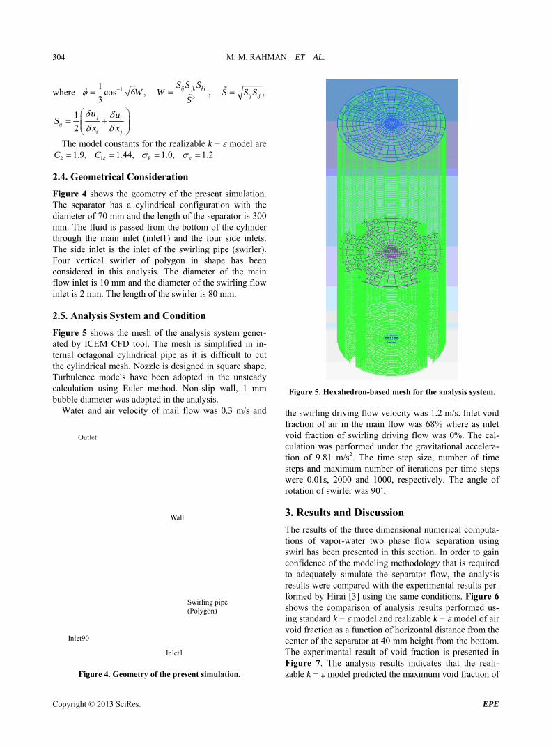
2.5. Analysis System and Condition
Figure 5 shows the mesh of the analysis system gener- ated by ICEM CFD tool. The mesh is simplified in in- ternal octagonal cylindrical pipe as it is difficult to cut the cylindrical mesh. Nozzle is designed in square shape. Turbulence models have been adopted in the unsteady calculation using Euler method. Non-slip wall, 1 mm bubble diameter was adopted in the analysis.
Water and air velocity of mail flow was 0.3 m/s and
Wall
Outlet
Inlet90
Inlet1
Swirling(Polygon
pipe )
Figure 4. Geometry of the present simulation.
Figure 5. Hexahedron-based mesh for the analysis system. the swirling driving flow velocity was 1.2 m/s. Inlet void fraction of air in the main flow was 68% where as inlet void fraction of swirling driving flow was 0%. The cal- culation was performed under the gravitational accelera- tion of 9.81 m/s2. The time step size, number of time steps and maximum number of iterations per time steps were 0.01s, 2000 and 1000, respectively. The angle of rotation of swirler was 90˚.
3. Results and Discussion
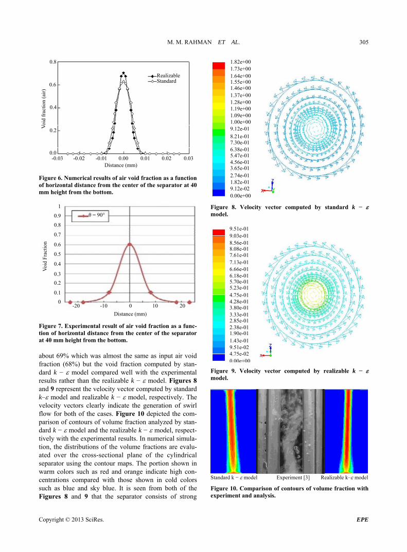
The results of the three dimensional numerical computa- tions of vapor-water two phase flow separation using swirl has been presented in this section. In order to gain confidence of the modeling methodology that is required to adequately simulate the separator flow, the analysis results were compared with the experimental results per- formed by Hirai [3] using the same conditions. Figure 6 shows the comparison of analysis results performed us- ing standard k − model and realizable k − model of air void fraction as a function of horizontal distance from the center of the separator at 40 mm height from the bottom. The experimental result of void fraction is presented in Figure 7. The analysis results indicates that the reali- zable k − model predicted the maximum void fraction of
8.21e-017.30e-016.38e-015.47e-014.56e-013.65e-012.74e-01Figure 6. Numerical results of air void fraction as a function
of horizontal distance from the center of the separator at 40 mm height from the bottom.
1.82e-019.12e-02
Distance (mm)
θ = 90°
0.8
0 10 20-10 -20
0.9
1
0.7
0.6
0.5
0.4
0.3
0.2
0.1
0
Voi
d Fr
actio
n
Figure 7. Experimental result of air void fraction as a func- tion of horizontal distance from the center of the separator at 40 mm height from the bottom. about 69% which was almost the same as input air void fraction (68%) but the void fraction computed by stan- dard k − model compared well with the experimental results rather than the realizable k − model. Figures 8 and 9 represent the velocity vector computed by standard k– model and realizable k − model, respectively. The velocity vectors clearly indicate the generation of swirl flow for both of the cases. Figure 10 depicted the com- parison of contours of volume fraction analyzed by stan- dard k − model and the realizable k − model, respect- tively with the experimental results. In numerical simula- tion, the distributions of the volume fractions are evalu- ated over the cross-sectional plane of the cylindrical separator using the contour maps. The portion shown in warm colors such as red and orange indicate high con- centrations compared with those shown in cold colors such as blue and sky blue. It is seen from both of the Figures 8 and 9 that the separator consists of strong
0.00e+00
Figure 8. Velocity vector computed by standard k − model.
swirling flow of high velocity around the center and weak swirling flow of low velocity near the wall. The strong swirling flow in the center results in centrifugal forces that propel the liquid phase (water) to the outer free vortex region, where water is collected and reside in the weak swirling intensity region (Figure 9). Thus, pure vapor phase will flow through the exit region (outlet). The higher volume fraction computed by realizable k − model than the standard k − model (in Figure 6) is due to the higher centrifugal forces generated at the center of the separator in case of realizable k − model than that of standard k − model. The reason is because the real- izable k − model underestimates the turbulence viscos- ity and overestimates the swirling velocity (Figures 8 and 9). In Figure 10, some discrepancies in flow pattern between the experimental and simulation results are ob- served which might be due to the turbulence modeling. In the k– models, the governing equations are averaged in time, thus the detailed bubble behaviors are homoge- nized. In order to calculate such a detailed behavior of bubbles, more elaborate turbulence model such as large eddy simulation (LES), which does not use time-aver- aging approach, is needed.
4. Conclusion
The numerical methodology presented herein establishes that the proposed innovative separator has the potentially significant value in effectively separating the vapor-wa- ter two phase flow in BWR. The standard k − turbu- lence model and realizable k − turbulence models are able to predict the flow features inside the separator such as void fraction and velocity distribution. The velocity vectors clearly indicate the generation of swirl flow for both of the cases. The results of the numerical simulation were compared with the experimental data and were found in reasonable agreement. The analysis revels that
the maximum air void fraction with realizable k − model was almost the same as input air void fraction but the void fraction computed by standard k − model compared better with the experimental results than the realizable k − model. Some discrepancies in flow pat- tern between the experimental and simulation results are observed which might be due to the difference of nozzle shape. However, a more detailed model is necessary to reach in the final conclusion.
REFERENCES [1] Y. Saito, G. Aoyama, H. Souma and T. Nakao, “Analysis
of Droplet Behavior in BWR Separator,” Journal of Nu- clear Science and Technology, Vol. 31, No. 4, 1994, pp. 349-335. doi:10.1080/18811248.1994.9735160
[2] S. Hirai and S. Yokobori, “Innovative Two Phase Flow Separation Using Swirling Fluidics,” Proceedings of the Annual Meeting of Japan Society of Fluid Mechanics, Kochi, September 2012 (in Japanese).
[3] S. Hirai, “Innovative Two Phase Flow Separation Using Swirling Fluidics,” Master Thesis, Tokyo City University, Tokyo, 2012 (in Japanese).
[5] B. E. Launder and D. B. Spalding, “Lectures in Mathe- matical Models of Turbulence,” Academic Press, London, 1972.
[6] T. H. Shih, W. W. Liou, A. Shabbir, Z. Yang and J. Zhu, “A New k – Eddy-Viscosity Model for High Reynolds Number Turbulent Flows—Model Development and Vali- dation,” Computers Fluids, Vol. 24, No. 3, 1995, pp. 227- 238. doi:10.1016/0045-7930(94)00032-T
[7] W. C. Reynolds, “Fundamentals of Turbulence for Tur- bulence Modeling and Simulation,” Lecture Notes for Von Karman Institute, Agard Report No. 755, 1987.


![A Parallel Compact Multi-dimensional Numerical … PARALLEL COMPACT MULTI-DIMENSIONAL NUMERICAL ALGORITHM WITH AEROACOUSTICS APPLICATIONS ALEX POVITSKY* AND PHILIP .]. MORRIS ¢ Abstract.](https://static.documents.pub/doc/80x56/5aeb54fa7f8b9ae5318d9568/a-parallel-compact-multi-dimensional-numerical-parallel-compact-multi-dimensional.jpg)


