TM 9-1265-370-10-1 Supersedes copy dated 22 January 1982 OPERATOR’S MANUAL MULTIPLE INTEGRATED LASER ENGAGEMENT SYSTEM (MILES) SIMULATOR SYSTEM, FIRING LASER: M60 (NSN 1265-01-085-1583) FOR M16A1 AND M16A2 RIFLE ( Not for use with Small Arms Transmitter (SAT) NSN 1265-01-236-6725 ) DISTRIBUTION STATEMENT A. Approved for public release; distribution is unlimited. HEADQUARTERS, DEPARTMENT OF THE ARMY JULY 1988
Transcript
TM 9-1265-370-10-1Supersedes copy dated 22 January 1982
OPERATOR’S MANUAL
MULTIPLE INTEGRATED LASER
ENGAGEMENT SYSTEM(MILES)
SIMULATOR SYSTEM, FIRING LASER: M60
(NSN 1265-01-085-1583)
FOR
M16A1 AND M16A2 RIFLE
( Not for use with Small Arms Transmitter (SAT) NSN 1265-01-236-6725 )
DISTRIBUTION STATEMENT A. Approved for public release; distribution is unlimited.
HEADQUARTERS, DEPARTMENT OF THE ARMY
JULY 1988
ALTHOUGH THE LASER LIGHT EMITTED BY MILES EQUIPMENT TRANSMITTERS ISCONSIDERED EYE SAFE BY THE BUREAU OF RADIOLOGICAL HEALTH, SUITABLEPRECAUTIONS MUST BE TAKEN TO AVOID POSSIBLE DAMAGE TO THE EYE FROMOVEREXPOSURE TO THIS RADIATED ENERGY. PRECAUTIONARY MEASURES INCLUDE THEFOLLOWING:
AVOID VIEWING LASER EMITTER AT CLOSE RANGE (LESS THAN 12 METERS).INCREASING THE DISTANCE FROM THE EYE TO THE LASER SOURCE GREATLYREDUCES THE RISKS OF OVEREXPOSURE.
AVOID VIEWING THE EMITTER DIRECTLY ALONG THE OPTICAL AXIS OFRADIATED BEAM.
ESPECIALLY AVOID VIEWING THE EMITTER DIRECTLY ALONG THE OPTICALAXIS OF THE BEAM THROUGH STABILIZED OPTICS SUCH AS BINOCULARS,TELESCOPES, OR PERISCOPES AT RANGES OF LESS THAN 75 METERS.
DO NOT LOAD MILES-EQUIPPED WEAPONS WITH LIVE OR THE WRONG BLANK AMMUNITION.USE ONLY M200 BLANK ROUNDS. IMPROPER AMMUNITION MAY CAUSE FATAL INJURIESTO PERSONNEL. REFER TO THE M16A1 OPERATOR'S MANUAL, TM 9-1005-249-10 FORADDITIONAL INFORMATION ON THE USE OF AMMUNITION.
PRIMER IS HIGHLY FLAMMABLE. DO NOT SPRAY NEAR HEAT, SPARKS, OR OPEN FLAME.NO SMOKING. USE ONLY IN WELL-VENTILATED AREA.
FOR INFORMATION ON FIRST AID, SEE FM21-11.
TECHNICAL MANUALTM 9-1265-370-10-1*
HEADQUARTERSDEPARTMENT OF THE ARMYWASHINGTON D.C., 15 JULY 1988
OPERATOR'S MANUALFOR
MULTIPLE INTEGRATED LASER ENGAGEMENT SYSTEM (MILES)SIMULATOR SYSTEM, FIRING, LASER: M60
(NSN 1265-01-085-1583)FOR
M16A1 AND M16A2 RIFLE
REPORTING ERRORS AND RECOMMENDING IMPROVEMENTS
You can help improve this manual. If you find any mistakes or if you know of a way toimprove the procedures, please let us know. Mail your letter, DA Form 2028(Recommended Changes to Publications and Blank Forms), or DA Form 2028-2 locatedin back of this manual direct to: Commander U.S. Army Simulation, Training, andInstrumentation Command (STRICOM), ATTN: AMSTI-LSM, 12350 Research Parkway,Orlando, FL 32826-3276. A reply will be furnished to you.
DISTRIBUTION STATEMENT A. Approved for publ ic release; distr ibut ion is unl imited.
The MILES equipment for the M16A1 or M16A2 is shown in Task 1 of thisTechnical Manual (TM). Use the picture with Task 1 as a guide for equipmentd i s t r i b u t i o n . B e s u r e t o i s s u e a c o p y o f t h i s T M a l o n g w i t h t h e M I L E Sequipment.
Equipment Return and Storage:
CAUTION
MAKE CERTAIN THAT THE MWLD TORSO ANDHELMET HARNESSES ARE COMPLETELY DRYBEFORE STORAGE IN TRANSIT CASE.
When receiving equipment for storage, always inspect the returned equipmentusing Task 14 in this TM for guidance.
Return all MILES equipment and the TMs to their transit cases.
Special Instruct ions for Infrequently Used Equipment:
If M16A1 or M16A2/MILES equipment is unused for 60 days, remove from transitcases and perform Tasks 1, 2, 3, 8, and 14.
1
Skills NeededTo Use This Manual
To use this manual, you should be able to:
3. Zero the M16A1 or M16A2r i f l e s i g h t s .(See TM 9-1005-249-10).
1.
2.
Put a blank-f ire attachment onthe M16A1 or M16A2 rifle.
Load and fire blankamun i t i on .
4. Complete DA Form 2402.
If you can not do all of the abovetasks, ask your NCO or ins t ructorto show you how. When you can doal l these tasks, go on to the nextpage.
3
How to Use This ManualBefore you use any M161A1 or M16A2/MILES equipment, read this manual.
T h e f i r s t p a r t o f t h e m a n u a l b r i e f l y e x p l a i n s t h e p u r p o s e o f t h eequipment and how it is used.
Then comes step-by-step guidance for every task you need to do withthe M16A1 or M16A2/MILES equipment.
In the remainder of this manual, general reference to both the M16A1and M16A2 will be made simply as "M16"; information that applies to apart icular type weapon wil l specify which type.
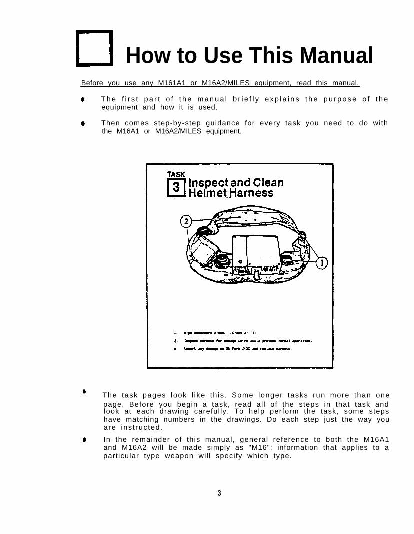
The task pages look l ike th is . Some longer tasks run more than onepage. Before you begin a task, read al l of the steps in that task andlook at each drawing careful ly. To help perform the task, some stepshave matching numbers in the drawings. Do each step just the way youare ins t ruc ted.
3
HOW TO USE THIS MANUAL (CONTINUED).
and the completed DA Form-2402 to your NCOIC.
Do each task in the order it occurs in the manual.
DON’T JUMP AHEAD - DON’T SKIP ANY STEPS -
I f your equipment has a prob lem you can ' t f ix us ing th is manual , repor ti t on DA Form 2401. To get a replacement, turn in the faulty equipment
In the back o f th is manual is a l is t o f abbrev ia t ions and an exp lanat iono f t e rms (g lossa ry ) used i n t h i s manua l . I f you read a wo rd you don ' tunderstand, check the abbreviat ions or glossary for an explanation.
General InformationThis manual shows you how to ope ra te and ma in ta in t he M16 /MILES l ase rs i m u l a t o r e q u i p m e n t . T h e o p e r a t o r a n d m a i n t e n a n c e t a s k s a r el isted in the Table of Contents on i and i i .
Purpose of Equipment:
The M16/MILES simulator is a battery-powered laser transmitter and detectorsystem. The simulator al lows real ist ic combat training without the hazards ofusing live ammunition.
Forms and Records:
a. Reports of Maintenance or Equipment Replacement.
Department of the Army forms and procedures used for equipment maintenancewill be those prescribed by DA PAM 738-750, The Army Maintenance ManagementSystem (TAMMS).
b. Reporting Equipment Improvement Recommendations (EIRs).
EIRs can and must be submitted by anyone who is aware of an unsatisfactorycondition with the equipment design or use. It is not necessary to show a newdesign or l is t a bet ter way to per form a procedure, jus t s imply te l l why thedesign is unfavorable or why a procedure is dif f icult . EIRs may be submittedon SF 368. Mai l d i rec t to :
Commander, U.S. Army Armament, Munitions and Chemical CommandATTN: AMSMC-QADRock Island, IL 61299-6000
A reply wil l be furnished to you.
4
C. Hand Receipts Manual
Hand receipts for Components of End Item (COEI), Basic Issue Items (BII), andAdd i t i ona l Au tho r i za t i on L i s t (AAL) i t ems a re pub l i shed i n a Hand Rece ip tmanual, TM 9-1265-370-10-1-HR. This manual is publ ished to aid in propertyaccountab i l i ty and is ava i lab le through: Commander , The U.S. Army Adju tantGeneral Publications Center, 2800 Eastern Boulevard, Baltimore, MD 21220.
Equipment DescriptionCapabilities and Features:
Major features of the M16/MILES include an eye-safe Laser transmitter mountedo n t h e b a r r e l o f t h e r i f l e . T h i s t r a n s m i t t e r i s a c t i v a t e d b y t h e s o u n d o fblank cartr idges being f ired.
The M16/MILES system can be operated in temperatures from -35° C (-31° F) to62° C (144° F).
I t permi ts tac t ica l sk i l l s to be pract iced under rea l is t ic cond i t ions.
The laser t ransmi t ter sends inv is ib le laser ( l igh t ) beams toward the target .I f the laser beam hits the target, detector assemblies on the target sense thebeam, and cause an alarm to sound.
Battery Information:
The M16/MILES system uses a BA-3090/U, 9 volt alkaline battery which providesapproximately 100 hours of power.
5
Location of Components:
1.2.
Helmet harness)Torso harness )-MWLD
3.4.
Weapon key receptacleYellow Weapon Key
5.6 .
TransmitterTransmitter (rear view)
7.8.
AlarmBlank fire attachment
6
How it Works:
The M16/MILES works much l ike a rea l M16. However , ins tead of f i r ing l iveammunition, the M16/MILES fires blank ammunition and a laser (light) beam attargets .
The targets wear MWLDs equipped with laser detector assemblies and alarms.When a laser beam from a transmitter str ikes a soldier 's MWLD, an alarmsounds. To shut off the alarm, the soldier must remove the yellow key fromhis weapon transmitter and put i t into a receptacle on his MWLD. With thek e y r e m o v e d f r o m t h e t r a n s m i t t e r , i t w i l l n o t o p e r a t e . R e m o v i n g t h eweapon's capabi l i ty to f i re a laser beam simulates a combat "ki l l ."
The M16/MILES operator also wears an MWLD. His alarm may be triggered bylaser fire from other MILES-equipped weapons.
How the M16/MILES is Used:
After the M16/MILES transmitter and MWLD have been instal led and tested,you wil l be ready to begin the training exercise.
To begin , p lace a b lank- f i re a t tachment on your r i f le and load i t w i thblank ammnunition.
Turn the transmitter yellow weapon key to the ON position.
Aim and f ire. The laser t ransmi t ter w i l l operate unt i l you run out o fblank ammnunition.
Limitations of Equipment:
The M16/MILES laser transmitter has the same range and operational capabilitiesa s t h e M 1 6 r i f l e , b u t a d i r t y l a s e r t r a n s m i t t e r l e n s m a y r e d u c e t h ee f f ec t i ve r ange o f t he t r ansm i t t e r . The l ase r i s on l y e f f ec t i ve aga ins texposed personnel wearing MWLDs. Automat ic f i re in the b lank- f i re mode foran ex tended pe r i od o f t ime cou ld resu l t i n l ase r t r ansm i t t e r f a i l u re . I ft h e t r a n s m i t t e r b e c o m e s t o o h o t t o t o u c h , s t o p f i r i n g . W a i t u n t i lt ransmitter has cooled off before f i r ing again.
7
1
TASK 1 Get This EquipmentFrom Your NCOIC
8
2TASK 2
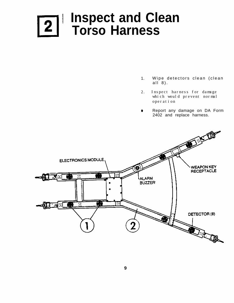
Inspect and CleanTorso Harness
1. W i p e d e t e c t o r s c l e a n ( c l e a na l l 8 ) .
2. Inspect harness for damage which would prevent normal operation
Report any damage on DA Form2402 and replace harness.
9
3
TASK 3 Inspect and CleanHelmet Harness
1. Wipe detectors clean. (Clean al l 5).
2. Inspect harness for damage which would prevent normal operation.
Report any damage on DA Form 2402 and replace harness.
10
4TASK 4 Put on Torso Harness
If you are wearing them,remove t he suspende rs f r omyour web gear.
Remove your web belt and layit next to the harness asshown.
1.
2.
3.
NOTE
The ha rness shou ld l ook l i keth is w i th the a larm above theelectronic module.
Fasten both clips to the belt.
With your web belt at thebottom, raise the harness andthen lower it over your head.
NOTE
I f you are carry ing a PRC-77rad io , place harness over ther a d i o s o t h a t r e a r d e t e c t o r sa re no t cove red by t he rad ioor i ts harness.
4. Fasten your web belt. Connecth a r n e s s t o t h e b e l t . A d j u s tharness so electronics moduleis a t the back of your co l lar ,a t the co l la r l ine .
11
TASK 5 Put Helmet Harnesson Helmet
NOTE
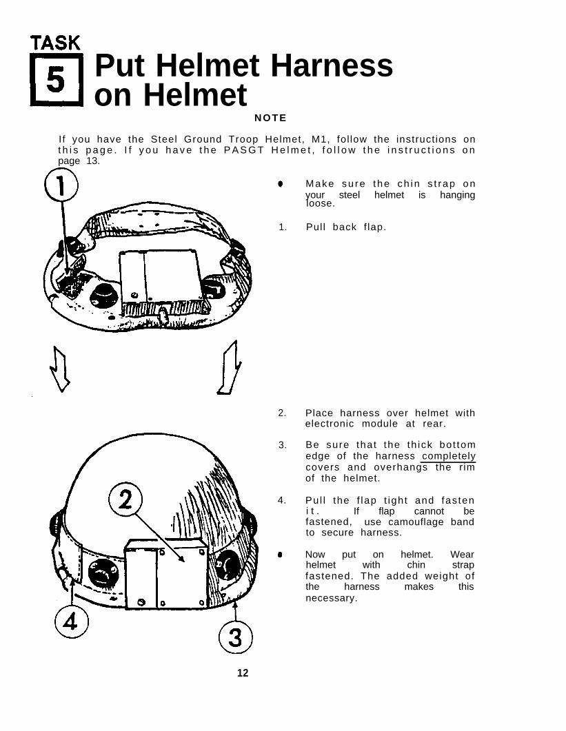
I f you have the Steel Ground Troop Helmet, M1, fol low the instruct ions ont h i s p a g e . I f y o u h a v e t h e P A S G T H e l m e t , f o l l o w t h e i n s t r u c t i o n s o npage 13.
1.
2.
3.
4.
Make su re t he ch in s t rap onyour steel helmet is hangingloose.
Pull back f lap.
Place harness over helmet withelectronic module at rear.
Be sure that the th ick bot tomedge of the harness completelycovers and overhangs the r imof the helmet.
Pu l l the f lap t ight and fas teni t . If flap cannot befastened, use camouflage bandto secure harness.
Now put on helmet. Wearhelmet with chin strapfastened. The added weight ofthe harness makes thisnecessary.
12
5
TASK 5
VELCRO MOUNTING INSTRUCTIONS FOR PASGT HELMETS
NOTE
These instructions pertain only to the PASGTHelmet. If you have the Steel Ground TroopHelmet, M1, follow the instructions on page 12.If your PASGT Helmet already has five patchesof Ve lcro ins ta l led, sk ip to the ins t ruc t ionson page 14.
PASGT Helmets require three to five patches of Velcro glued to the outside tohold the MWLD helmet harness in place. The Velcro patches must be attached inthe proper posit ion on the helmet so that they wi l l mate with the patches ofVelcro which are attached to the harness.
1. Slip the MWLD helmet harness over the PASGT helmet so that electronicsbox is at the rear.
2. Make sure the th ick bot tom edge of the harness complete ly covers andoverhangs rim of the helmet in front.
3. Pul l the harness t ight and mark the helmet areas where the f ive Velcropatches on the harness touch the helmet. Remove the harness.
4. Cut five patches of Velcro (approximately 2 inches square).
WARNING
TAPE MOUNTING PRIMER IS HIGHLY FLAMMABLE. DONOT SPRAY NEAR HEAT, SPARKS, OR OPEN FLAME.NO SMOKING. USE ONLY IN WELL-VENTILATED AREAS.
5. Spray tape mounting primer over the marked areas where the Velcro will beattached. Al low primer spray to dry for at least 5 minutes.
6. Remove backing paper from patches of Velcro and firmly press the patchesonto the helmet.
13
5
TASK 5
PASGT HELMET HARNESS MOUNTING
1. Sl ip harness over helmet so that the electronic box is at the rear.
2. Make sure the heavy cable overhangs the lip of the helmet in front.
3. Ad jus t harness so that the f ive p ieces o f Ve lcro on the ins ide o f theha rness l i ne up w i t h Ve l c ro p i eces a t t ached t o t he ou t s i de o f you rhelmet.
4. Pul l harness ends in the direct ion of the arrows to t ighten harness.
5. Fasten Velcro f laps t ight ly .
When you wear your helmet, fasten the chinstrap. The added weight ofthe harness makes this necessary.
14
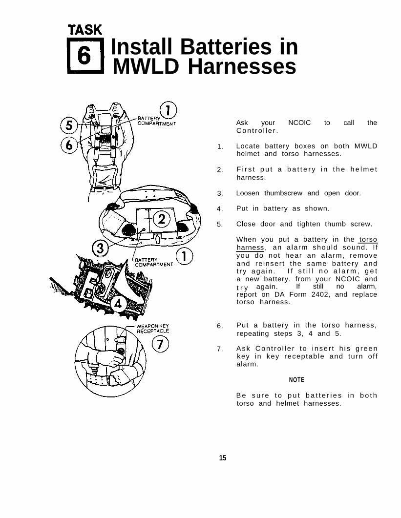
TASK 6 Install Batteries inMWLD Harnesses
1.
2.
3.
4.
5.
6.
7.
Ask your NCOIC to call theCon t ro l l e r .
Locate battery boxes on both MWLDhelmet and torso harnesses.
F i r s t p u t a b a t t e r y i n t h e h e l m e tharness.
Loosen thumbscrew and open door.
Put in battery as shown.
Close door and tighten thumb screw.
When you put a battery in the torsoharness, an a larm should sound. I fyou do not hear an a larm, removeand re inser t the same bat tery andt r y aga in . I f s t i l l n o a l a r m , g e ta new battery. from your NCOIC andt r y again. If still no alarm,report on DA Form 2402, and replacetorso harness.
Put a battery in the torso harness,repeating steps 3, 4 and 5.
Ask Con t ro l l e r t o i nse r t h i s g reenkey in key receptable and turn of falarm.
NOTE
B e s u r e t o p u t b a t t e r i e s i n b o t htorso and helmet harnesses.
15
TASK 7
Test Operation of MWLD
1. Ask Controller to test your torso harness using "Near Miss" mode.
2. When he fires, your a larm should sound br ie f ly . If you do not hear analarm, remove and reinsert the same battery in the torso harness and testagain. I f s t i l l n o a l a r m ,Task 6) and test again.
replace the battery in the torso harness (seeI f s t i l l n o a l a r m , report on DA Form 2402, and
replace the torso harness.
3. Ask Control ler to test helmet harness for an alarm. You must be wearingyour he lmet dur ing th is tes t . I f you do not hear an alarm, make surethat the bottom of the harness overhangs the entire rim of the helmet andtes t aga in . I f s t i l l n o a l a r m , remove and reinsert the same battery andtes t aga in . I f s t i l l n o a l a r m ,(see Task 6) and test again.
replace the battery in the helmet harnessIf still no alarm, ask a soldier whose MWLD
has already been checked and is operating properly to put on your helmetand test again. I f s t i l l n o a l a r m ,the helmet harness.
report on DA Form 2402 and replaceI f a f ter a re tes t the a larm sounds, repor t on DA
Form 2402 and replace your torso harness.
16
TASK 8 Inspect and CleanTransmitter
1. Remove any dirt or oil from thelens with a lens paper or a softcloth. Wet cloth to removestubborn d i r t .
2. Make sure foam microphone cover isdry and not caked with dirt orb lank- f i re res idue.
Check for damage which wouldp r e v e n t n o r m a l o p e r a t i o n o f t h et ransmi t te r .
Report any damage on DA form 2402.Replace transmitter.
17
9TASK 9
Put Battery in Transmitter
1. Flip latch and open door.
2.
3.
4.
I n s e r t a B A - 3 0 9 0 / U b a t t e r y a sshown.
Press door closed. Hold doorc l osed w i t h one hand , and f as tenclamp with other hand.
Press latch closed.
18
10
TASK 10 Place Transmitteron Barrel
I f y o u r w e a p o n i s e q u i p p e dwith an M203 Grenade Launcher,remove grenade launcher barrelbefore ins ta l l ing t ransmi t ter .
1. Open both spring clamps.
2. Flip the diamond-shaped piecesto the outside.
3. Ho ld t r ansm i t t e r w i t h c l ampsfacing and the lenspoint ing forward.
4.
5.
W i t h t h e r i f l e h e l d u p s i d edown, put transmitter onbarre l so gu ides s t radd le thef r o n t s i g h t . Close diamond-s h a p e d p i e c e s o v e r b a r r e l .Then close the locking pieces.Lock both clamps.
R e i n s t a l l g r e n a d e l a u n c h e rbarre l .
19
11
TASK 11
Blank-Fire Operation
1.
2.
3.
4.
5.
A t t a c h b l a n k - f i r e a t t a c h m e n t . P u tt o p c o v e r e d s i d e o f b l a n k - f i r eat tachment a t an ang le , as shown,t o p r o t e c t t h e t r a n s m i t t e r l e n sfrom muzzle blast.
Insert magazines loaded with blankcartridges into weapon.
I n s e r t y e l l o w k e y i n t r a n s m i t t e r .Turn to WEAPON ON position.
Chamber first round.
While watching t h e F I R I N G l i g h t ,f i r e one round . The lamp shouldl i g h t b r i e f l y .
If you do not see a light, firea g a i n . I f s t i l l n o l i g h t , r e m o v ea n d r e i n s e r t t h e s a m e b a t t e r y i nt r a n s m i t t e r a n d t e s t a g a i n . I fs t i l l n o l i g h t , replace battery andt e s t a g a i n . I f s t i l l n o l i g h t ,report on DA Form 2402. Replacethe t ransmi t te r .
I f lamp goes out or does not l ightwhi le you are f i r ing the M16 in ane x e r c i s e , r e p l a c e t r a n s m i t t e rbat tery .
20
TASK 12
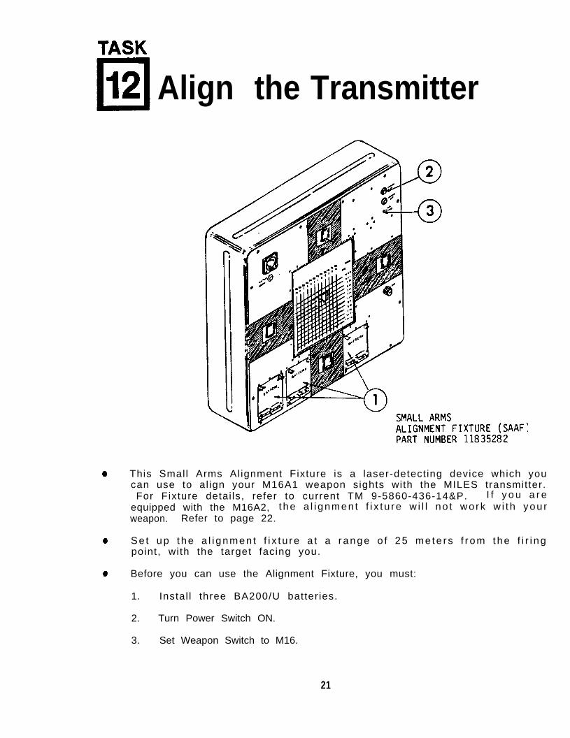
Align the Transmitter
This Small Arms Al ignment Fixture is a laser-detect ing device which youcan use to al ign your M16A1 weapon sights with the MILES transmitter.For Fixture detai ls, refer to current TM 9-5860-436-14&P. I f y o u a r e
equipped with the M16A2, the a l i gnmen t f i x t u re w i l l no t wo rk w i t h you rweapon. Refer to page 22.
Se t up t he a l i gnmen t f i x t u re a t a r ange o f 25 me te rs f r om the f i r i ngpoint, with the target facing you.
Before you can use the Alignment Fixture, you must:
1. Instal l three BA200/U batteries.
2. Turn Power Switch ON.
3. Set Weapon Switch to M16.
21
TASK 12
Th i s Sma l l A rms A l i gnmen t F i x tu re , pa r t number 9353020 , i s a l ase rdetecting device which you can use to align your M16A2 weapon sights withthe MILES transmitter. (For f ix ture deta i ls re fer to cur rent TM 9-5860-436-14&P).
Se t up t he a l i gnmen t f i x t u re a t a r ange o f 25 me te rs f r om the f i r i ngpoint, with the target facing you.
Before you can use the Alignment Fixture, you must:
1. Instal l three BA-200/U batteries.
2. Turn Power Switch ON.
3. Ensure that the M16A1, M16A2, M60 target face is installed.
4. Set WEAPON SIGHT SELECT Switches to the posit ions l isted in theupper left corner of the target face; use the numbers for the weaponbeing aligned (M16A1 or M16A2).
22
TASK 12
The M16A1 and M16A2 transmitters can be al igned in either blank-f ire ordry-f ire mode.
NOTE
To put your weapon in dry-fire mode see page 24.
I f you r weapon i s i n b l ank - f i r e mode , be su re i t i s l oaded w i t h b lankammunition.
Adjust the sights:
Turn the f ront s ight unt i l base o f s ight is f lush wi th i ts we l l .Center the windage on the rear sight.Set rear sight to use unmarked (short range) aperture.
Assume the prone supported firing position.
1. Aim and f ire one round at the target 's bul l 's-eye.
2. The target d isp lays te l l you what to do next . For example, i f ther ight d isp lay shows 8, move t he rea r s i gh t 8 c l i c ks t o t he r i gh t .I f the lower d isp lay shows 4, move the f ront s ight 4 c l icks down,e tc .
3. When the displays show four "zeros" (plus or minus one count) thet ransmi t ter is a l igned.
4. If no display shows, see instructions on page 25.
23
12
TASK 12
To align the sights of your weapon when in the dry-fire mode, you must performthe fol lowing steps:
1.
2.
Obtain a dry-fire cable from the accessory bag in the SAAF.
Remove and secure p ro tec t i ve cap from J-1 connector on rear oft ransmi t te r .
3.
4.
5.
6.
7.
8.
9.
Attach plug on dry-f ire cable to J-1 connector ensuring that slot on pluga l i gns w i t h " tooth" on connector . Screw lock ing s leeve down secure ly( f inger t igh t , use no too ls) .
Attach clips on cable to vent holes on upper hand guards of rifle.
Wrap Velcro tie loop around upper hand guard slip ring.
Cock rifle and open trigger guard.
Rou te cab le unde r dus t cove r and gen t l y push t r i gge r bu t t on up ove rt r i g g e r .
Have a Contro l ler inser t a green key in to your r i f le t ransmi t ter . TurnKey. P ress t r i gge r bu t t on and l i gh t shou ld i l l um ina te i n t he w indowabove J-1 connector. When it does, have the controller remove green key.
Insert your yel low weapons key into transmitter. Turn to ON posit ion.
10. P lace togg le swi tch (on the rear o f the t ransmi t ter ) to pos i t ion markedSEMI.
11. Adjust your sights according to the display on the SAAF (see steps 1 thru4, page 23).
24
TASK 12
Verify alignment of your weapon sight:
I f no d i sp lay appea rs on A l i gnmen t F i x tu re a t c l ose range , f i r e a t anearby soldier who is wearing an operable MWLD. Whi le f i r ing , observet h e f i r i n g l i g h t . I t shou ld l i gh t when t he t r ansm i t t e r f i r es . I f n oMWLD alarm sounds or no f ir ing l ight appears, replace the battery in thet ransmi t te r . I f s t i l l n o r e s p o n s e , report on DA Form 2402. Replacet ransmi t te r .
1. From a distance of 100 meters, fire at a soldier wearing an operableMWLD. The alarm should sound continuously indicating a "kill".
2. I f alarm does not sound or sounds brief ly, indicating a "near miss,"your t ransmi t ter may not be proper ly a l igned. Real ign us ing theAlignment Target.
25
13TASK 13
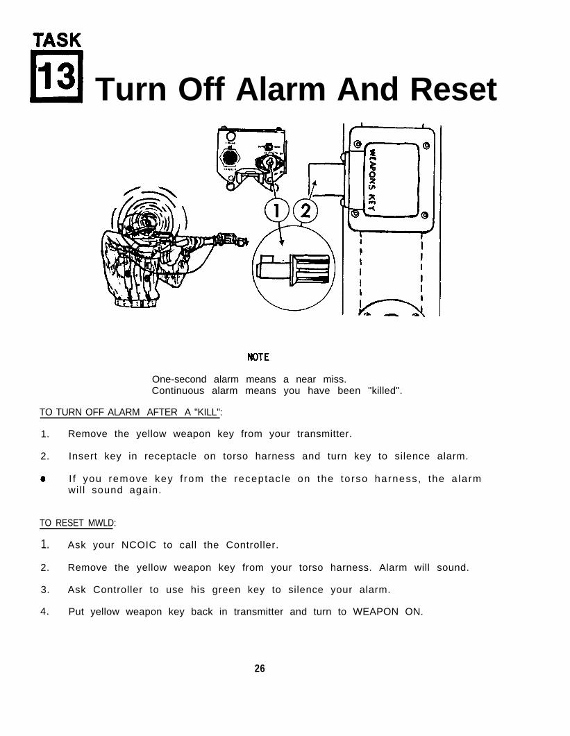
Turn Off Alarm And Reset
One-second alarm means a near miss.Continuous alarm means you have been "killed".
TO TURN OFF ALARM AFTER A "KILL":
1. Remove the yellow weapon key from your transmitter.
2. Insert key in receptacle on torso harness and turn key to silence alarm.
I f you remove key f rom the receptac le on the torso harness, the a larmwil l sound again.
TO RESET MWLD:
1. Ask your NCOIC to call the Controller.
2. Remove the yellow weapon key from your torso harness. Alarm will sound.
3. Ask Controller to use his green key to silence your alarm.
4. Put yellow weapon key back in transmitter and turn to WEAPON ON.
26
14
TASK 14 Inspect, Clean, andReturn MILES Equipment
Unload your weapon
1.
2.
3.
4.
5.
6.
7.
8.
9.
10.
Remove MWLD torso and helmet harnesses.
Remove both batteries from MWLD and close doors (see Task 6).
Do Tasks 2 and 3: Inspect and clean harness assemblies.
Remove M16 transmitter from barrel (see Task 10).
Make sure that yellow weapon key is in transmitter.
Remove transmitter battery and close door (see Task 9).
Do Task 8: Inspect and clean transmitter.
Remove blank-fire attachment from M16A1.
Make sure that you have all your equipment (see Task 1).
Return a l l MILES equipment , M16, b lank- f i re a t tachment , and anyunused blank ammunition to your NCOIC. You may be asked to returny o u r M I L E S e q u i p m e n t t o i t s t r a n s i t c a s e . I f s o , f o l l o w t h einstructions on the next page.
27
TASK 14
Transit Case Loading Instruct ions
The transit case holds 20 complete M16A1 or M16A2 MILES systems.
1. Remove yellow weapon keys from each transmitter. P lace keys inspaces provided.
2. Insert 20 transmitters, lens down, into spaces provided.
3. Fold torso harnesses and place them in space provided.
4. Fold helmet harnesses and place them on top of torso harnesses.
5. Two spaces are provided for holding Operator's Manuals. Place 10copies of the manual in each space.
28
APPENDIX A
REFERENCES
A-1. SCOPE
This appendix l ists al l forms, f ield manuals, and technical manuals referencedin this manual.
A-2 FORMS
SF 368
DA Form 2028-2
DA Form 2062
DA Form 2402
DA Form 2404
A-3. FIELD MANUALS
FM 21-11
A-4. TECHNICAL MANUALS
Operator's Manual:M16A1 Rifle
Hand Receipt for SimulatorSystem, Firing Laser:M60 for M16A1 Rifle
Al ignment Fixture, Laser:M1 for MILES Small Arms
A-5 MISCELLANEOUS PUBLICATIONS
AR 310-2
SB 11-6
DA PAM 738-750
Quality Deficiency Report
Recommended Changes to Equipment TechnicalPubl icat ions
Hand Receipt
Exchange Tag
Equipment Inspection and MaintenanceWork Sheet
Field Manual: F i rs t A id for So ld iers
TM 9-1005-249-10
TM 9-1265-370-10-1-HR
TM 9-5860-436-14&P
Ident i f ica t ion and Dis t r ibut ion o f DAPublicat ions
Dry Battery Supply Data
The Army Maintenance Management System(TAMMS)
29
APPENDIX B
COMPONENTS OF END lTEM AND BASIC ISSUE ITEMS LISTS
SECTION I. INTRODUCTION
This appendix lists integral components of the M16A1 and M16A2/MILES system.A l l o f t h e s e i t e m s m u s t b e r e t u r n e d t o y o u r N C O I C f o l l o w i n g a t r a i n i n gexercise.
Explanation of columns:
National Stock Number: Stock requisition number
Descript ion: Lines 1 and 2 give a brief i tem descript ion.Line 3 lists the Federal Supply Code forManufacturer (FSCM) and the reference number.
U/M: Unit of Measure
Qty: Quanti ty of i tem furnished.
Illustration Number: Number of i l lustrat ion that shows i tem.
SECTION II. COMPONENTS OF END ITEM
NationalStock Number
1265-079-5264
None Assigned
1 1
1 1
1 21265-01-075-4893
Descript ionFSCM & Part Number
I l l u s t r a t i o n U/M Qty Number
M16A1 Laser Transmitter e a .Assembly(19200), 11748801
M16A2 Laser Transmitter e a .Assembly (alternate item)(19200), 9353050
Man Worn Laser Detector ea.Assembly(19200), 11748808
Th is append i x l i s t s add i t i ona l i t ems you w i l l need to operate the M16/MILESsystem.
Explanation of Columns:
Na t i ona l s t ock numbers , desc r i p t i on , un i t o f measu re , and quan t i t i es a reprov ided to he lp you ident i fy and request the addi t ional i tems you wi l l needto operate the M16/MILES system.
National Descript ion I l l u s t r a t i o nStock Number FSCM & Part Number U/M Qty
6135-01-063-1978 *Ba t te r y , 9 vo l t ea. 3 Task 1(80058) BA-3090/U
*Dry bat tery l is ted is used wi th theequipment. I t w i l l not bep resh ipped au toma t i ca l l y bu t i s t ob e r e q u i s i t i o n e d i nn e c e s s a r y f o r t h e p a r t i c u l a r
quant i t ies
organization in accordance with SB11-6.
31
APPENDIX D
EXPENDABLE SUPPLIES AND MATERIALS LIST
This appendix l ists the expendable supplies and materials which you wil l needto operate and maintain the M16/MILES system.
Explanation of Columns:
National stock numbers, descript ions and unit of measure are provided to helpyou identi fy and request the expendable supplies and materials used with theM16/MILES system.
National Descript ionStock Number FSCM & Part Number U/M
6640-00-240-5851
8010-01-040-0947
8315-01-111-7170
Paper, Lens(81349), NNN-P-40
Primer, Tape(19200), 11749034
Fastener Tape, Hook(19200), 11749428
pk.
cn
ea.
32
REFERENCE INFORMATION
T h i s s e c t i o n i n c l u d e s t h e n o m e n c l a t u r e c r o s s r e f e r e n c e l i s t , l i s t o fabbreviat ions, and explanations of terms (glossary) used in this manual.
A. NOMENCLATURE CROSS REFERENCE LIST
Common Name Off icial Nomenclature
Alignment Target Small Arms Alignment Fixture
Controller Gun
Helmet Harness
Controller's Gun, Simulator System, Laser
Detector Assembly, Simulator System,Laser: Man Worn
M16A1 TransmitterM16A2 Transmitter
Transmitter Assembly, Simulator System,Laser: For M16A1 (or M16A2) Rifle
Torso Harness Detector Assembly, Simulator System,Laser: Man Worn
B. LIST OF ABBREVIATIONS
MILES
MWLD
C. GLOSSARY
Contro l ler
Controller Gun
Control ler Key
Helmet Harness
K i l l
Multiple Integrated Laser EngagementSystem
Man Worn Laser Detector
The umpire or referee in a MILES trainingexercise.
The device used to test MILES detectorsystems. May also be used to disqualifysoldiers or vehicles from the exercise.
The green key used by the Controller toreset MILES transmitters. Also used toreset the MWLD.
The part of the laser detector assemblyworn on a combat helmet.
In a MILES training exercise, acontinuous alarm sounds indicating thedetector assembly was hit by a laserbeam. The yellow weapon key is removedfrom the transmitter and put in thedetector assembly to si lence alarm. TheM16A1 transmitter wi l l not operate withweapon key removed.
33
Laser Beam
Laser Detector Assembly
Laser Transmitter
Man Worn Laser Detector
Near Miss
Simulator
Torso Harness
Trigger Cable Assembly
Weapon Key
Weapon Key Receptacle
In MILES, a harmless invisible beam oflight which simulates weapon fire.
A device which senses the laser beamd i r e c t e d a t i t . When the assembly senses alaser beam, i t t r iggers an a larm.
A device that sends the laser beam.
T h e h e l m e t a n d t o r s o a s s e m b l y w o r n b ypersonnel which senses a laser beamd i rec ted a t i t .
A one-second alarm from the MWLD indicateslaser f i re directed towards you.
A t ra in ing dev ice which takes the p lace o frea l equ ipment and which has many of i tscha rac te r i s t i c s .
T h e p a r t o f t h e l a s e r d e t e c t o r a s s e m b l yworn on the upper body.
A MILES device used with Dry-Fire.
This yellow key has two uses:1. To turn on the M16 transmitter.2. To silence alarm when it sounds, remove
key from transmitter and insert in MWLDweapon.
A small device on the MWLD which receivesthe yellow weapon key to shut off alarm.
34
By Order of the Secretary of the Army:
CARL E. VUONOGeneral. United States Army
Chief of Staff
Official:
R. L DILWORTHBrigadier General. United States Army
The Adjutant General
DISTRIBUTION:
To be distributed in accordance with DA Form 12-40, Operator's Maintenancerequirements for MILES Simulator Sys, Firing, Laser, M60 (for M16A1 Rifle).
U . S . G O V E R N M E N T P R I N T I N G O F F I C E : 1 9 9 3 - 3 4 2 - 4 2 1 ( 8 0 1 0 4 )
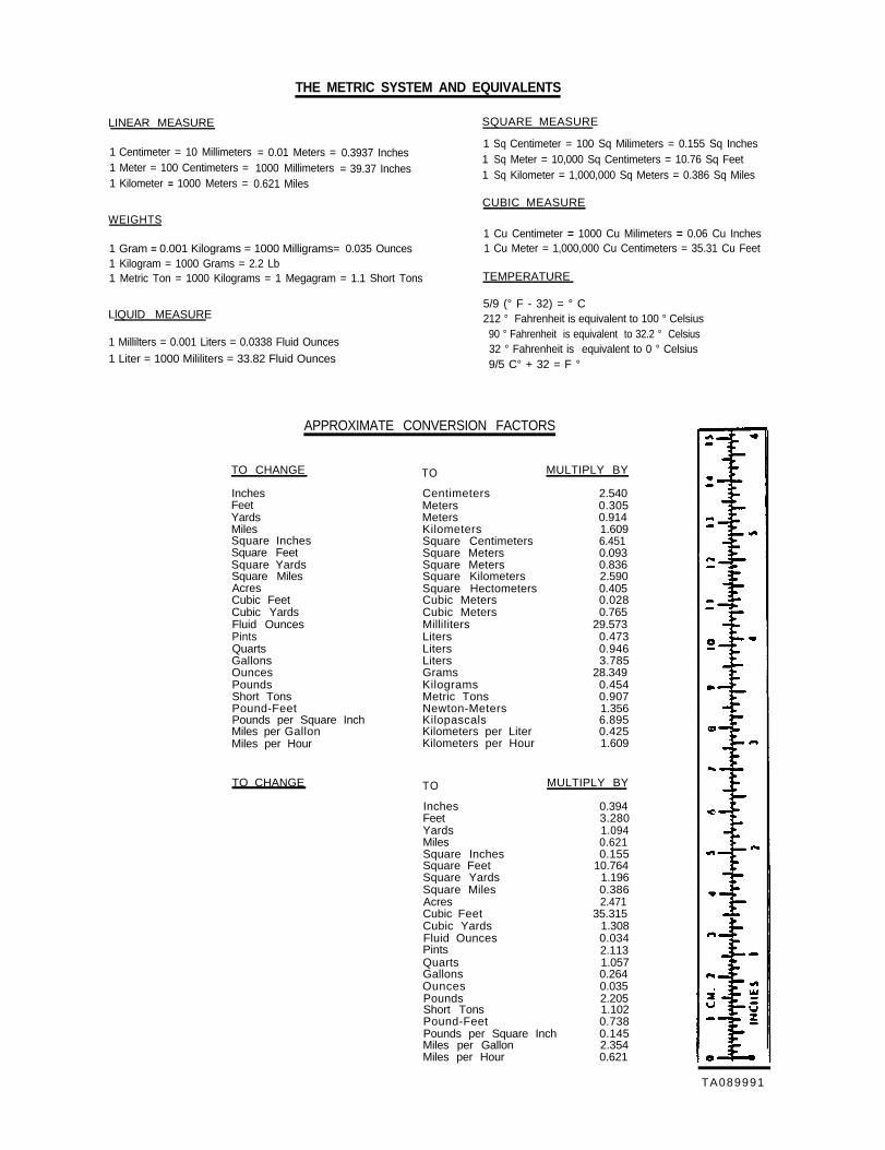
THE METRIC SYSTEM AND EQUIVALENTS
LINEAR MEASURE
1 Centimeter = 10 Millimeters = 0.01 Meters = 0.3937 Inches1 Meter = 100 Centimeters = 1000 Millimeters = 39.37 Inches1 Kilometer = 1000 Meters = 0.621 Miles
Inches 0.394Feet 3.280Yards 1.094Miles 0.621Square Inches 0.155Square Feet 10.764Square Yards 1.196Square Miles 0.386Acres 2.471Cubic Feet 35.315Cubic Yards 1.308Fluid Ounces 0.034Pints 2.113Quarts 1.057Gallons 0.264Ounces 0.035Pounds 2.205Short Tons 1.102Pound-Feet 0.738Pounds per Square Inch 0.145Miles per Gallon 2.354Miles per Hour 0.621
TA089991
PIN: 050402-000
This fine document...
Was brought to you by me:
Liberated Manuals -- free army and government manuals
Why do I do it? I am tired of sleazy CD-ROM sellers, who take publicly available information, slap “watermarks” and other junk on it, and sell it. Those masters of search engine manipulation make sure that their sites that sell free information, come up first in search engines. They did not create it... They did not even scan it... Why should they get your money? Why are not letting you give those free manuals to your friends?
I am setting this document FREE. This document was made by the US Government and is NOT protected by Copyright. Feel free to share, republish, sell and so on.
I am not asking you for donations, fees or handouts. If you can, please provide a link to liberatedmanuals.com, so that free manuals come up first in search engines:
<A HREF=http://www.liberatedmanuals.com/>Free Military and Government Manuals</A>


![b]quinolines via L-proline Facile construction of densely ... · Facile construction of densely functionalized thiopyrano ... TM 3b TM 3b 1-19 ... 9 370 380 440 450](https://static.documents.pub/doc/80x56/5adddb4a7f8b9aa5088d62ef/bquinolines-via-l-proline-facile-construction-of-densely-construction-of-densely.jpg)