39
Topology Optimization – Driven Design Development for Automotive Components Ronald J. Banchak FE-DESIGN Optimization Inc., USA Markus Stephan and Michael Böhm FE-DESIGN GmbH Germany
Topology Optimization – Driven Design Development for Automotive Components
Ronald J. BanchakFE-DESIGN Optimization Inc., USA
Markus Stephan and Michael Böhm
FE-DESIGN GmbH Germany
Overview
• Short Introduction into Topology Optimization for CFD
– Basic Concepts
– Optimization Workflow
• Automotive Application Examples
– Automotive HVAC Flow Splitter
– Intercooler Intake Hose
– Exhaust Gas Recirculation Cooler
• Summary
Support
and
Coaching
Software-
Development
Engineering,
Services,
Customization
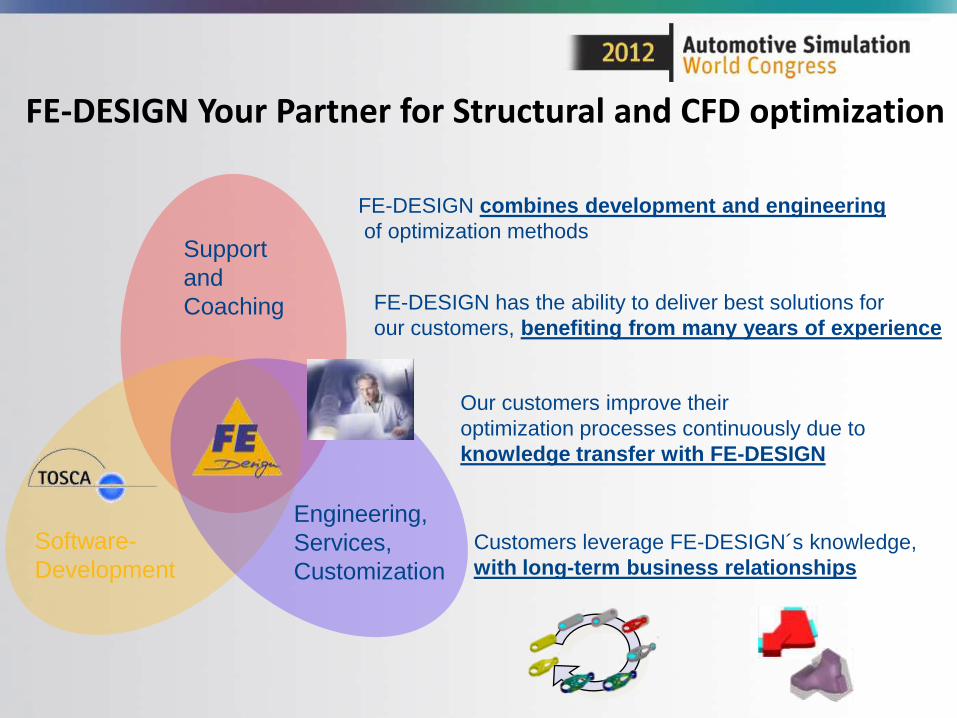
FE-DESIGN Your Partner for Structural and CFD optimization
FE-DESIGN combines development and engineering
of optimization methods
FE-DESIGN has the ability to deliver best solutions for
our customers, benefiting from many years of experience
Our customers improve their
optimization processes continuously due to
knowledge transfer with FE-DESIGN
Customers leverage FE-DESIGN´s knowledge,
with long-term business relationships
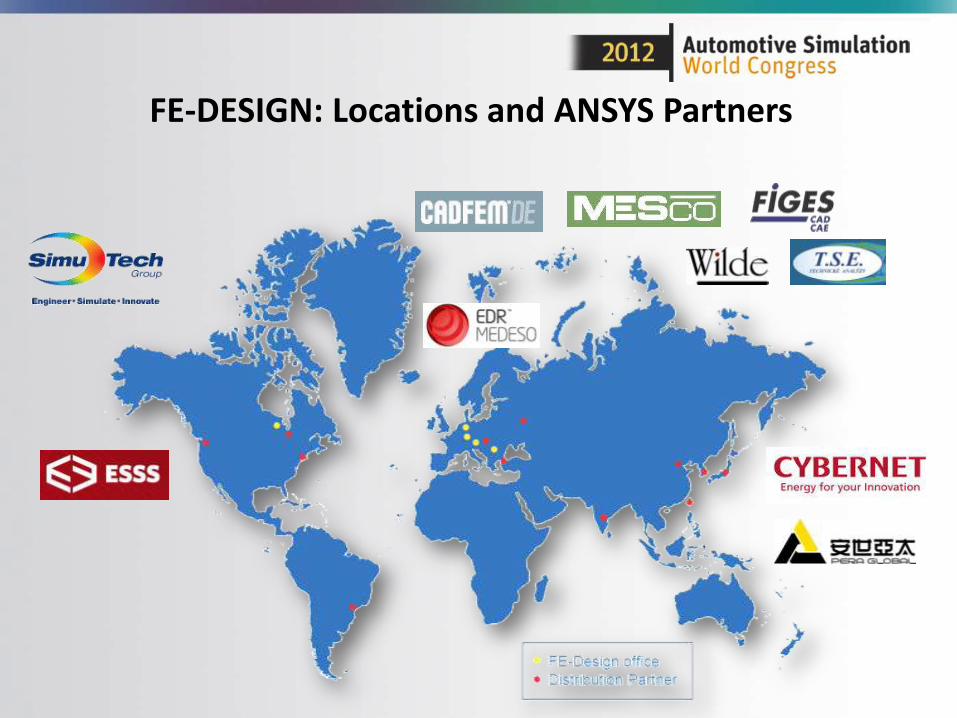
FE-DESIGN: Locations and ANSYS Partners
FE-DESIGN Optimization Inc
• Located in Des Plaines, IL (Chicago)
• An Affiliate of FE-DESIGN GmbH, Germany
• Dedicated to supporting our US customers
• Ron Banchak (General Manager), Mark Miller (Senior Technical Consultant)
FE-DESIGN Optimization Inc.
2700 South River Road, Suite 302
Des Plaines, IL 60018
FE-DESIGN: Customers (extract)
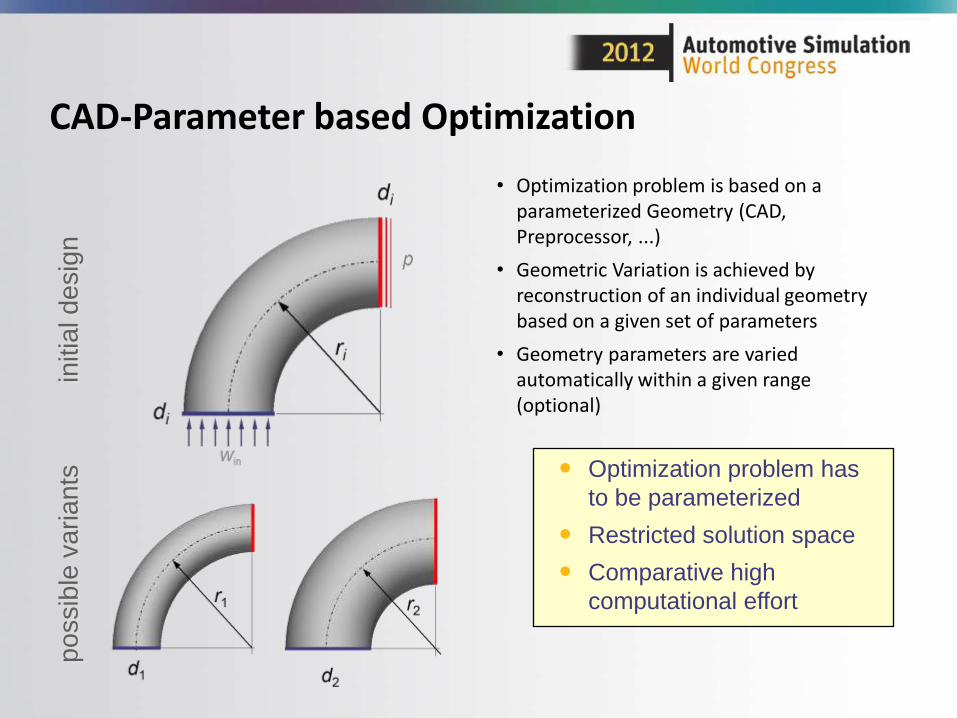
CAD-Parameter based Optimization
• Optimization problem is based on a parameterized Geometry (CAD, Preprocessor, ...)
• Geometric Variation is achieved by reconstruction of an individual geometry based on a given set of parameters
• Geometry parameters are varied automatically within a given range (optional)
po
ssib
le v
aria
nts
initia
l d
esig
n
Optimization problem has
to be parameterized
Restricted solution space
Comparative high
computational effort
8
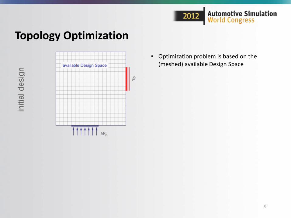
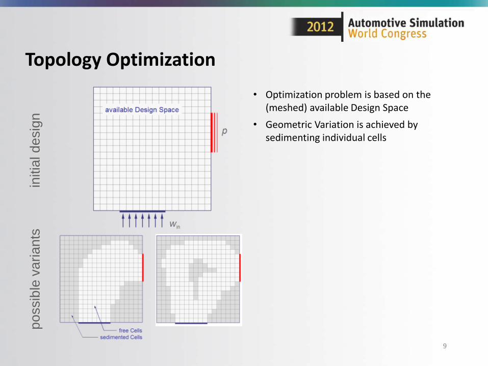
Topology Optimization
initia
l d
esig
n
• Optimization problem is based on the (meshed) available Design Space
9
Topology Optimization
po
ssib
le v
aria
nts
• Optimization problem is based on the (meshed) available Design Space
• Geometric Variation is achieved by sedimenting individual cells
initia
l d
esig
n
10
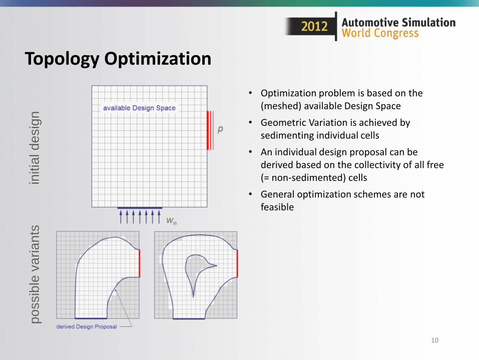
Topology Optimization
po
ssib
le v
aria
nts
• Optimization problem is based on the (meshed) available Design Space
• Geometric Variation is achieved by sedimenting individual cells
• An individual design proposal can be derived based on the collectivity of all free (= non-sedimented) cells
• General optimization schemes are not feasible
initia
l d
esig
n
11
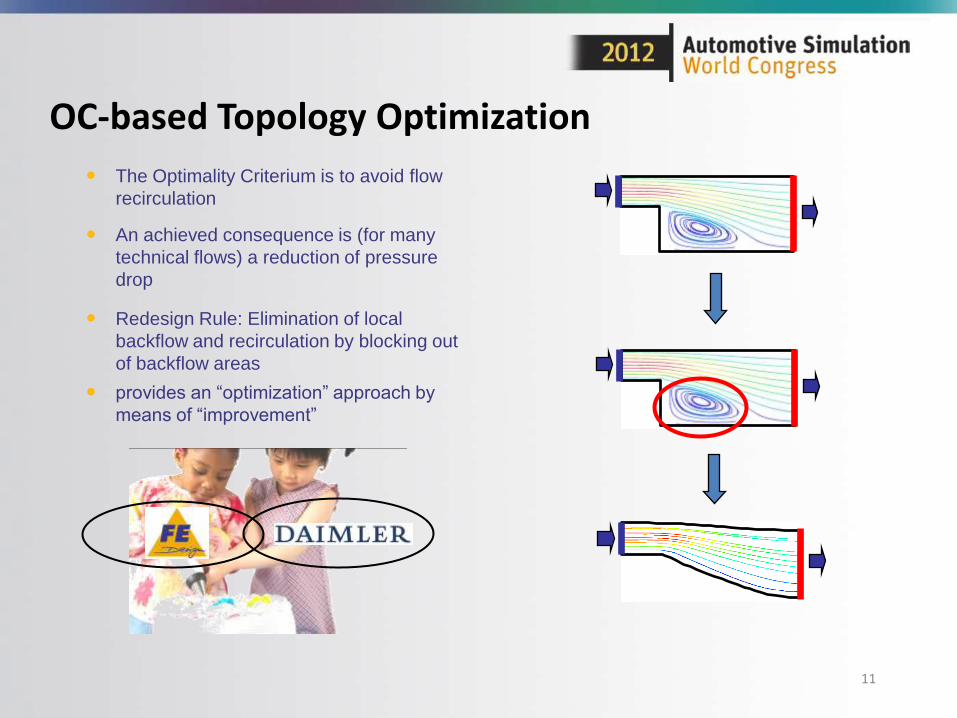
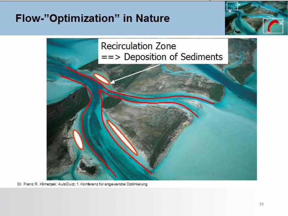
Redesign Rule: Elimination of local
backflow and recirculation by blocking out
of backflow areas
provides an “optimization” approach by
means of “improvement”
The Optimality Criterium is to avoid flow
recirculation
OC-based Topology Optimization
An achieved consequence is (for many
technical flows) a reduction of pressure
drop
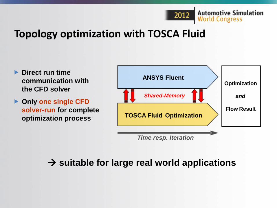
Direct run time
communication with
the CFD solver
Only one single CFD
solver-run for complete
optimization process
suitable for large real world applications
Topology optimization with TOSCA Fluid
ANSYS Fluent
TOSCA Fluid Optimization
Time resp. Iteration
Optimization
and
Flow Result
Shared-Memory
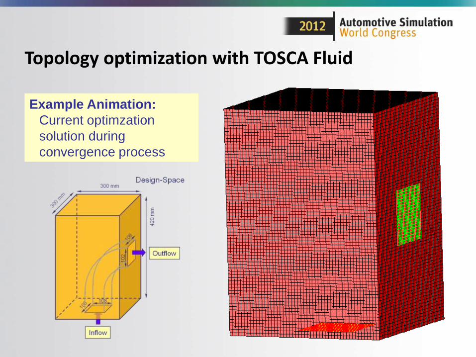
Example Animation:
Current optimzation
solution during
convergence process
Topology optimization with TOSCA Fluid
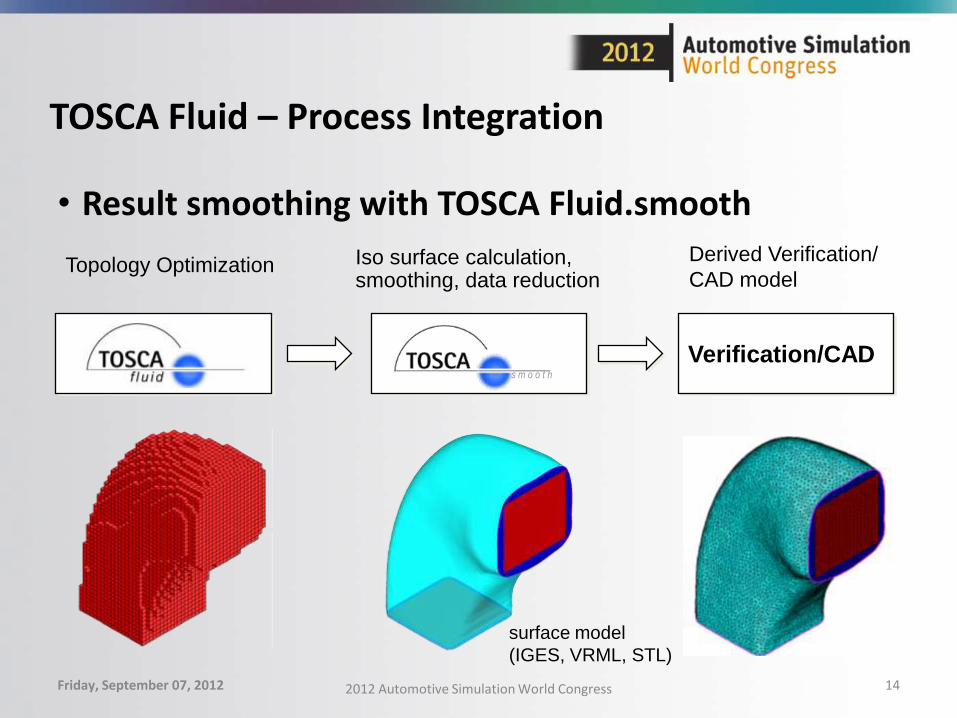
TOSCA Fluid – Process Integration
• Result smoothing with TOSCA Fluid.smooth
Friday, September 07, 2012 2012 Automotive Simulation World Congress 14
Topology OptimizationDerived Verification/
CAD model
Verification/CAD
Iso surface calculation, smoothing, data reduction
s m o o t h
surface model
(IGES, VRML, STL)
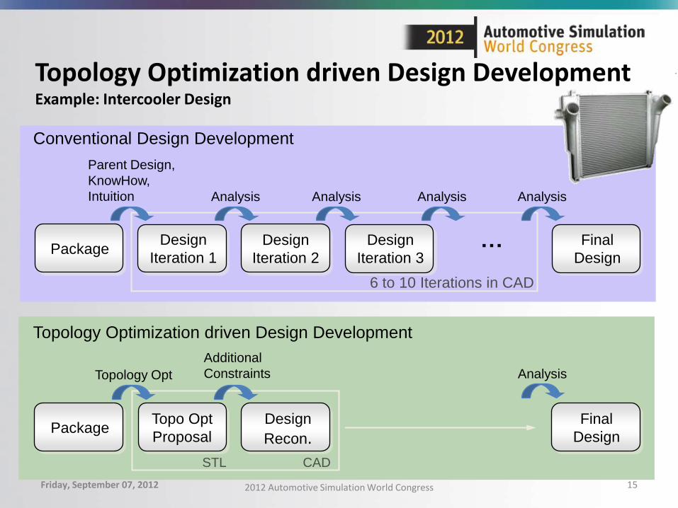
Topology Optimization driven Design DevelopmentExample: Intercooler Design
Friday, September 07, 2012 2012 Automotive Simulation World Congress 15
Conventional Design Development
Package
Topology Optimization driven Design Development
Design
Iteration 2
Design
Iteration 1
Design
Iteration 3
Final
Design
Topo Opt
Proposal
Design
Recon.
Final
DesignPackage
Topology Opt
Additional
Constraints
6 to 10 Iterations in CAD
Parent Design,
KnowHow,
Intuition Analysis
…
Analysis Analysis
Analysis
Analysis
CADSTL
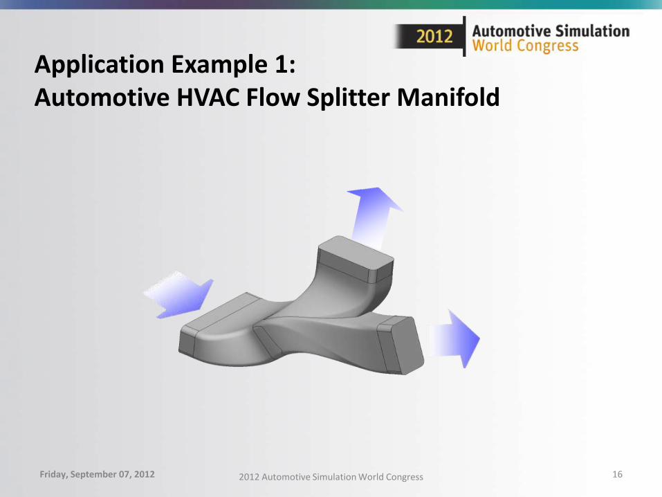
Application Example 1:Automotive HVAC Flow Splitter Manifold
Friday, September 07, 2012 2012 Automotive Simulation World Congress 16
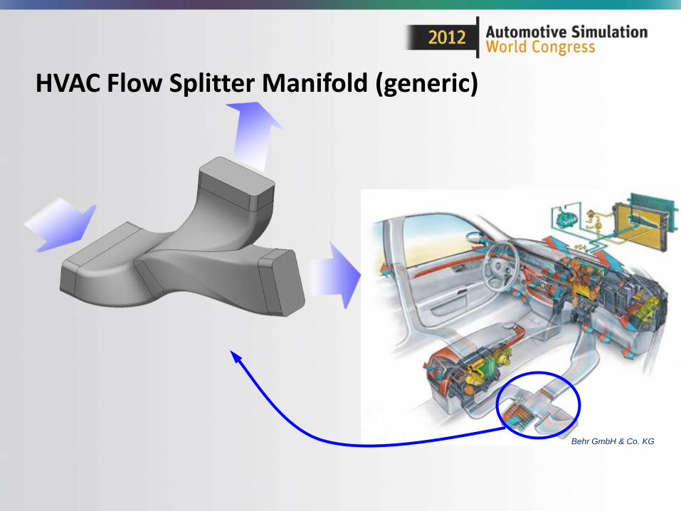
HVAC Flow Splitter Manifold (generic)
Behr GmbH & Co. KG
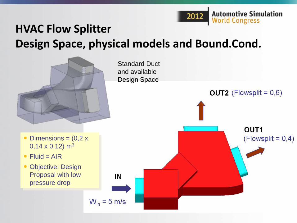
HVAC Flow SplitterDesign Space, physical models and Bound.Cond.
Dimensions = (0,2 x
0,14 x 0,12) m3
Fluid = AIR
Objective: Design
Proposal with low
pressure drop
Standard Duct
and available
Design Space
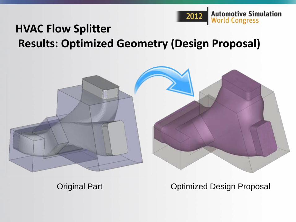
HVAC Flow SplitterResults: Optimized Geometry (Design Proposal)
Original Part Optimized Design Proposal
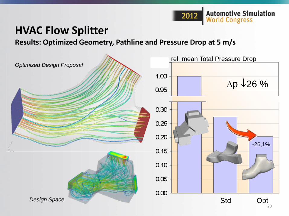
HVAC Flow SplitterResults: Optimized Geometry, Pathline and Pressure Drop at 5 m/s
20
Design Space
Optimized Design Proposalrel. mean Total Pressure Drop
Std Opt
-26,1%
p 26 %
Application Example 2:CFD Topology Optimization of an existing Intercooler Intake Hose
Friday, September 07, 2012 2012 Automotive Simulation World Congress 21
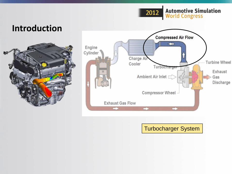
Introduction
Turbocharger System
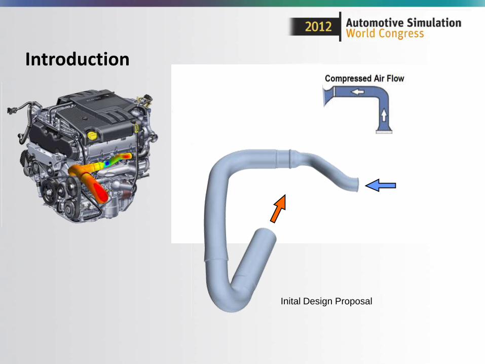
Introduction
Inital Design Proposal
Pathlines (colored with velocity magnitude)
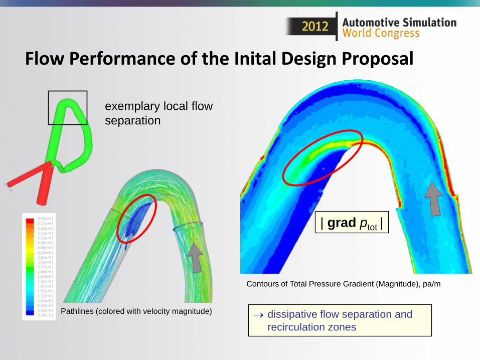
Flow Performance of the Inital Design Proposal
Contours of Total Pressure Gradient (Magnitude), pa/m
dissipative flow separation and
recirculation zones
| grad ptot |
exemplary local flow
separation
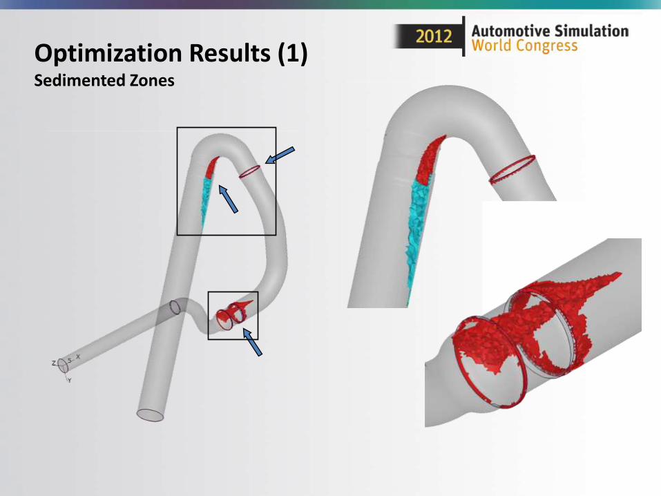
Optimization Results (1)Sedimented Zones
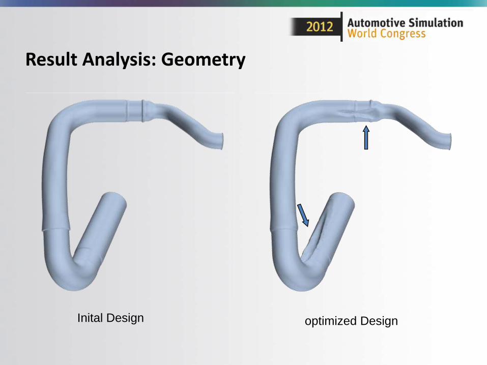
Result Analysis: Geometry
Inital Design optimized Design
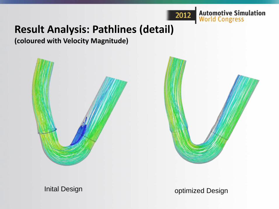
Result Analysis: Pathlines (detail) (coloured with Velocity Magnitude)
Inital Design optimized Design
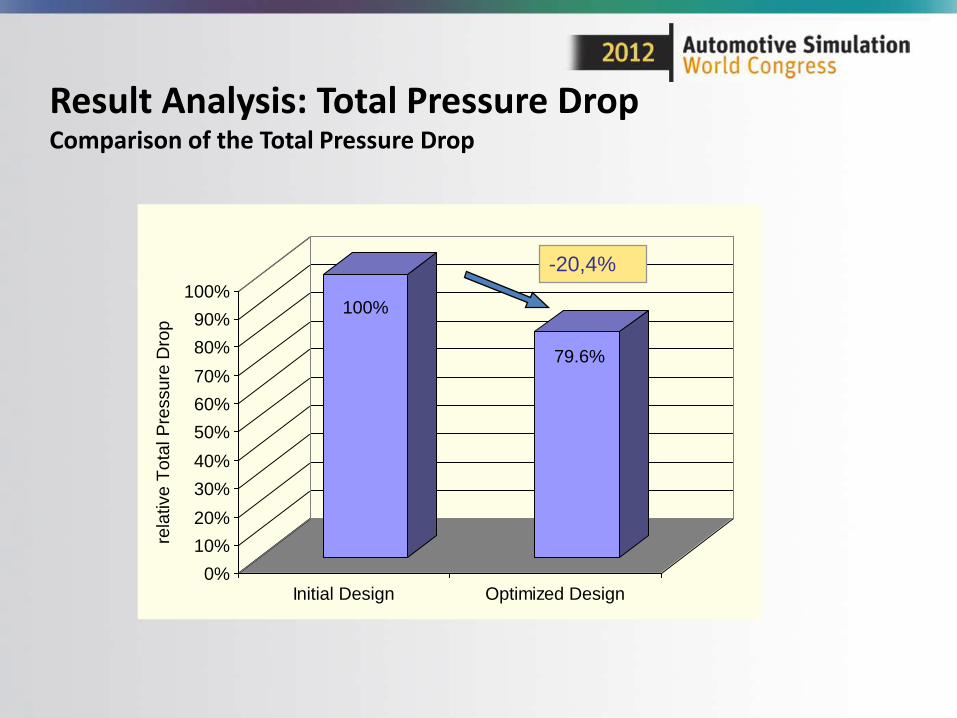
Result Analysis: Total Pressure DropComparison of the Total Pressure Drop
100%
79.6%
0%
10%
20%
30%
40%
50%
60%
70%
80%
90%
100%
rela
tive T
ota
l P
ressure
Dro
p
Initial Design Optimized Design
-20,4%
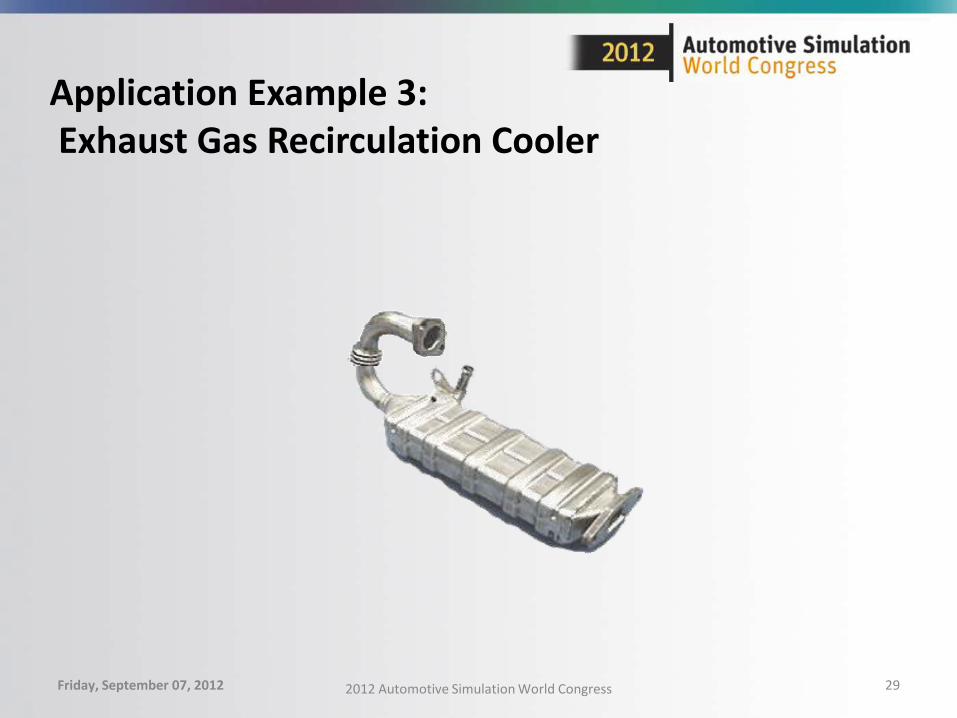
Application Example 3:Exhaust Gas Recirculation Cooler
Friday, September 07, 2012 2012 Automotive Simulation World Congress 29
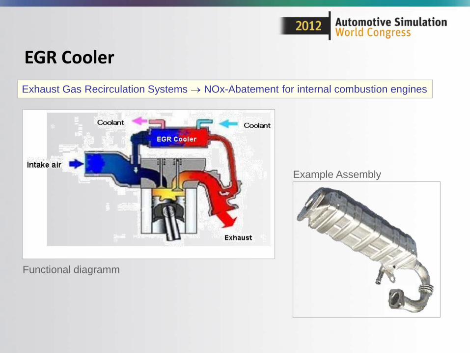
EGR Cooler
Exhaust Gas Recirculation Systems NOx-Abatement for internal combustion engines
Functional diagramm
Example Assembly
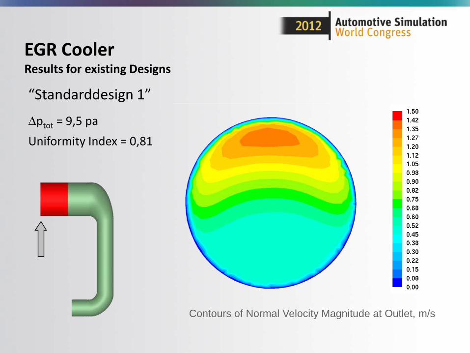
EGR CoolerResults for existing Designs
“Standarddesign 1”
ptot = 9,5 pa
Uniformity Index = 0,81
Contours of Normal Velocity Magnitude at Outlet, m/s
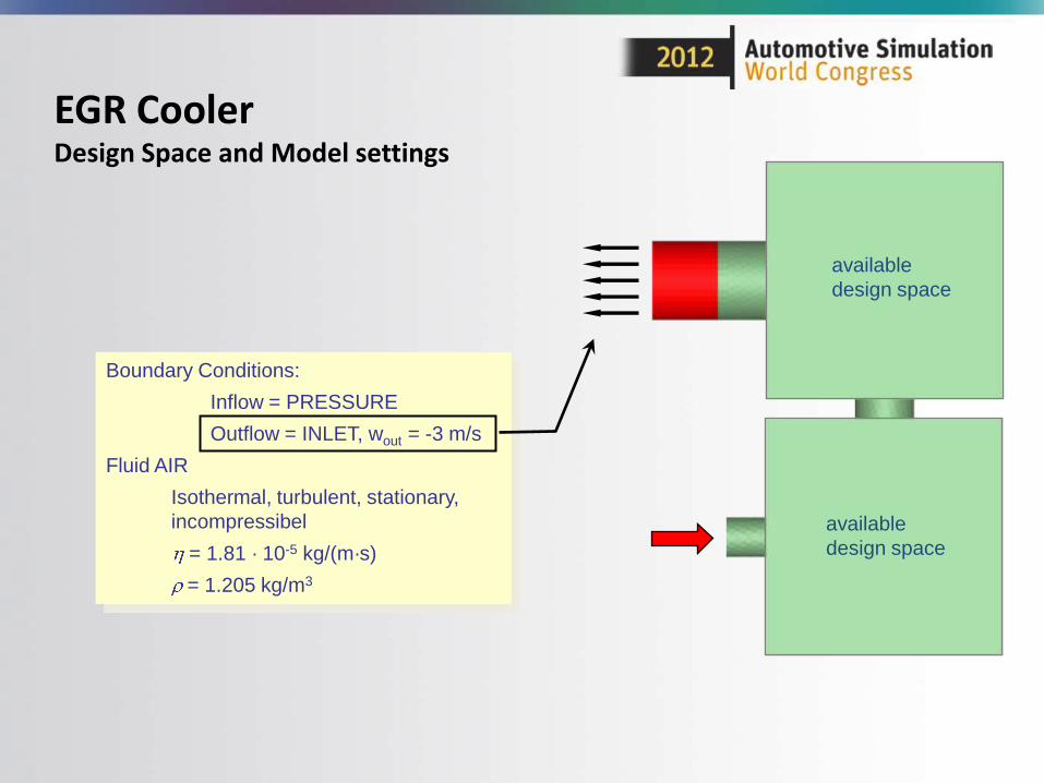
EGR CoolerDesign Space and Model settings
Boundary Conditions:
Inflow = PRESSURE
Outflow = INLET, wout = -3 m/s
Fluid AIR
Isothermal, turbulent, stationary,
incompressibel
= 1.81 · 10-5 kg/(m·s)
= 1.205 kg/m3
available
design space
available
design space
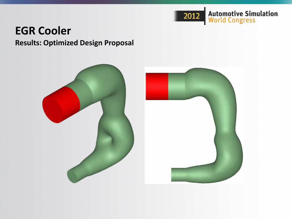
EGR CoolerResults: Optimized Design Proposal
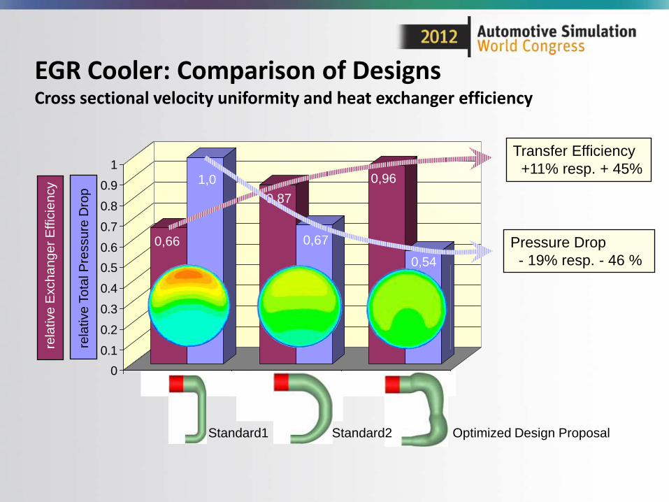
EGR Cooler: Comparison of DesignsCross sectional velocity uniformity and heat exchanger efficiency
0
0.1
0.2
0.3
0.4
0.5
0.6
0.7
0.8
0.9
1
Std 1 Std 2 Ver 1
Designvariante
0,54
rela
tive
To
tal P
ressu
re D
rop
rela
tive
Exch
an
ge
r E
ffic
ien
cy
0,67
1,0
0,66
0,87
0,96
Transfer Efficiency
+11% resp. + 45%
Pressure Drop
- 19% resp. - 46 %
Optimized Design ProposalStandard2Standard1
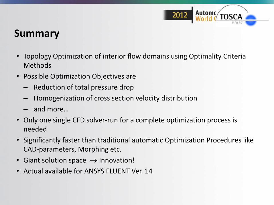
Summary
• Topology Optimization of interior flow domains using Optimality Criteria Methods
• Possible Optimization Objectives are
– Reduction of total pressure drop
– Homogenization of cross section velocity distribution
– and more…
• Only one single CFD solver-run for a complete optimization process is needed
• Significantly faster than traditional automatic Optimization Procedures like CAD-parameters, Morphing etc.
• Giant solution space Innovation!
• Actual available for ANSYS FLUENT Ver. 14
Appendix
39
40
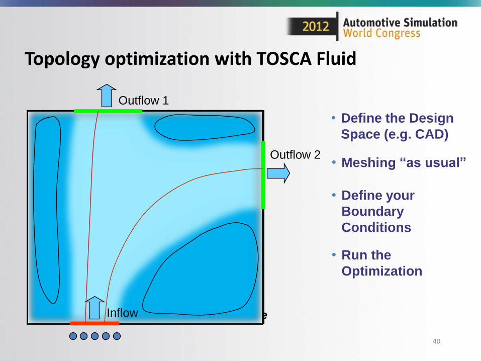
Design Space
Topology optimization with TOSCA Fluid
• Define the Design
Space (e.g. CAD)
Outflow 1
Outflow 2
Inflow
• Define your
Boundary
Conditions
• Run the
Optimization
• Meshing “as usual”
41
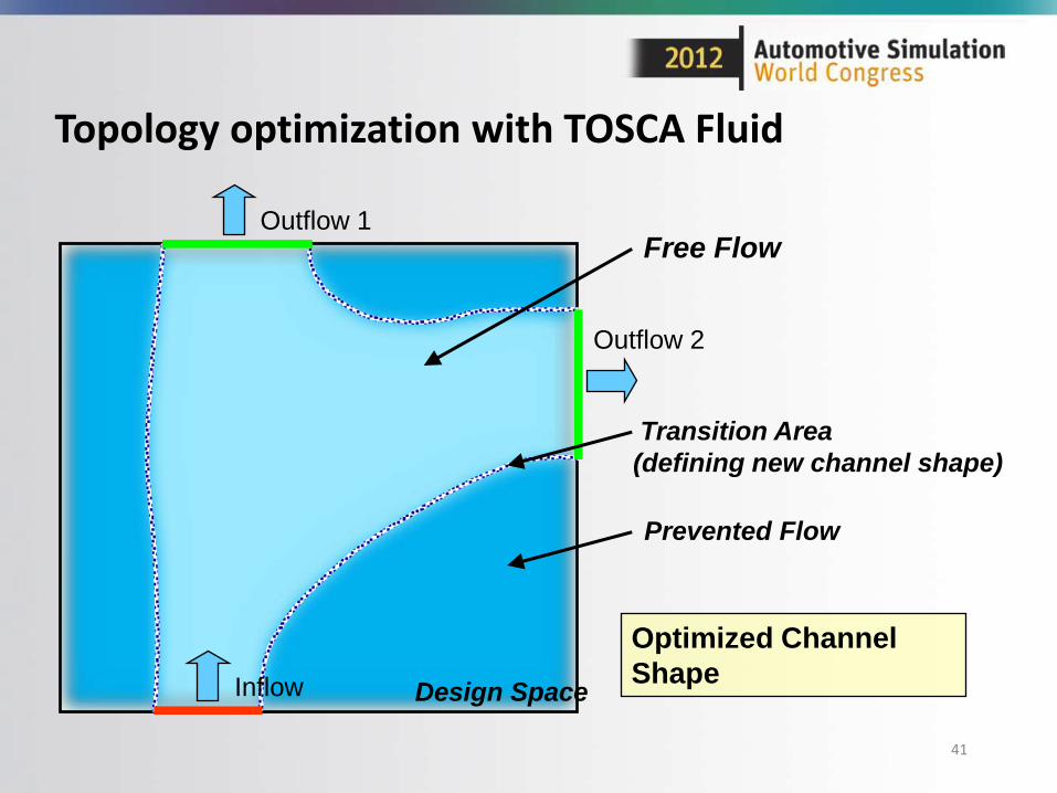
Topology optimization with TOSCA Fluid
Design Space
Outflow 1
Outflow 2
Inflow
Optimized Channel
Shape
Prevented Flow
Free Flow
Transition Area
(defining new channel shape)


