TR 101 202 V1.1.1 (1999-02) Technical Report Digital Video Broadcasting (DVB); Implementation guidelines for Data Broadcasting EBU UER European Broadcasting Union Union Européenne de Radio-Télévision
Transcript
TR 101 202 V1.1.1 (1999-02)Technical Report
Digital Video Broadcasting (DVB);Implementation guidelines for Data Broadcasting
EBUUER
European Broadcasting Union Union Européenne de Radio-Télévision
ETSI
TR 101 202 V1.1.1 (1999-02)2
ReferenceDTR/JTC-DVB-70 (b4o00ics.PDF)
KeywordsDVB, digital, video, data, broadcasting, TV
ETSI
Postal addressF-06921 Sophia Antipolis Cedex - FRANCE
Office address650 Route des Lucioles - Sophia Antipolis
3 Definitions and abbreviations ..................................................................................................................73.1 Definitions ......................................................................................................................................................... 73.2 Abbreviations..................................................................................................................................................... 7
4 Rules of operation ....................................................................................................................................94.1 Introduction........................................................................................................................................................ 94.2 Selection of the Appropriate Profile ................................................................................................................ 104.2.1 Fragmentation of Datagrams ...................................................................................................................... 114.3 Data Pipe.......................................................................................................................................................... 114.3.1 Usage of the Adaptation Field.................................................................................................................... 114.4 Asynchronous/Synchronized/Synchronous Data Streaming ............................................................................ 114.4.1 Usage of the Adaptation Field.................................................................................................................... 114.4.2 Asynchronous Data Streaming ................................................................................................................... 124.4.3 Synchronous/Synchronized Data Streaming............................................................................................... 124.4.4 Synchronous Data Streaming ..................................................................................................................... 124.4.5 Synchronized Data Streaming .................................................................................................................... 134.5 Multiprotocol encapsulation ............................................................................................................................ 134.5.1 Overview.................................................................................................................................................... 134.5.2 Data transport ............................................................................................................................................. 134.5.3 Information in the SI .................................................................................................................................. 144.6 Data Carousel................................................................................................................................................... 154.6.1 Introduction................................................................................................................................................ 154.6.2 Data Carousel Groups and SuperGroups.................................................................................................... 164.6.3 Use of the One-layer Data Carousel ........................................................................................................... 164.6.4 Use of the Two-layer Data Carousel .......................................................................................................... 164.6.4.1 The Data Carousel consists of a single Group the description of which is too large for a single
DownloadInfoIndication message......................................................................................................... 174.6.4.2 The Data Carousel delivers a single version of an application but supports a number of different
receiver profiles .................................................................................................................................... 174.6.4.3 The Data Carousel simultaneously delivers more than one version of an application for a single
receiver profile...................................................................................................................................... 174.6.5 Assignment and use of transactionId values............................................................................................... 174.6.6 Use of Descriptors Specific to the DVB Data Carousel ............................................................................. 184.6.6.1 Type descriptor..................................................................................................................................... 194.6.6.2 Name descriptor.................................................................................................................................... 194.6.6.3 Info descriptor ...................................................................................................................................... 194.6.6.4 Module link descriptor.......................................................................................................................... 194.6.6.5 CRC-32 descriptor................................................................................................................................ 194.6.6.6 Location descriptor............................................................................................................................... 194.6.6.7 Estimated download time descriptor..................................................................................................... 194.6.6.8 Group link descriptor............................................................................................................................ 194.6.6.9 Private descriptor.................................................................................................................................. 204.6.6.10 Compressed module descriptor............................................................................................................. 204.6.7 Information in the SI and PSI..................................................................................................................... 204.6.7.1 Descriptor in SI..................................................................................................................................... 204.6.7.2 Descriptors in PSI................................................................................................................................. 214.7 Object Carousel ............................................................................................................................................... 214.7.1 Introduction................................................................................................................................................ 214.7.2 Platform independence............................................................................................................................... 234.7.2.1 Overview .............................................................................................................................................. 23
ETSI
TR 101 202 V1.1.1 (1999-02)4
4.7.2.2 Supported U-U Objects ........................................................................................................................ 244.7.2.3 Transmission of objects ........................................................................................................................ 254.7.2.4 Object References................................................................................................................................. 264.7.2.5 Taps and associations ........................................................................................................................... 284.7.3 BIOP Control Structures ............................................................................................................................ 304.7.3.1 Interoperable Object Reference (IOR).................................................................................................. 304.7.3.2 BIOP Profile Body ............................................................................................................................... 314.7.3.3 Lite Options Profile Body..................................................................................................................... 334.7.3.4 Carousel NSAP address........................................................................................................................ 344.7.4 BIOP Messages .......................................................................................................................................... 354.7.4.1 Directory............................................................................................................................................... 354.7.4.2 File........................................................................................................................................................ 374.7.4.3 Stream................................................................................................................................................... 384.7.4.4 Service Gateway ................................................................................................................................... 404.7.4.5 StreamEvent.......................................................................................................................................... 414.7.5 Download Data Carousel Messages ........................................................................................................... 424.7.5.1 DownloadInfoIndication....................................................................................................................... 424.7.5.2 DownloadServerInitate ......................................................................................................................... 434.7.5.3 DownloadDataBlock ............................................................................................................................ 444.7.6 MPEG2 Sections ........................................................................................................................................ 444.7.7 Use of PSI descriptors................................................................................................................................ 444.7.7.1 Carousel identifier descriptor ............................................................................................................... 454.7.7.2 Association tag descriptor..................................................................................................................... 464.7.7.3 Stream identifier descriptor .................................................................................................................. 474.7.7.4 Deferred association tags descriptor ..................................................................................................... 474.7.8 Information in the SI and PSI..................................................................................................................... 484.7.8.1 SI Descriptor......................................................................................................................................... 484.7.8.2 Descriptors in PSI................................................................................................................................. 484.7.9 Assignment and use of transactionId values............................................................................................... 48
Annex A (informative): DSM-CC messages for Data Carousel.........................................................50
Intellectual Property RightsIPRs essential or potentially essential to the present document may have been declared to ETSI. The informationpertaining to these essential IPRs, if any, is publicly available for ETSI members and non-members, and can be foundin SR 000 314: "Intellectual Property Rights (IPRs); Essential, or potentially Essential, IPRs notified to ETSI in respectof ETSI standards", which is available free of charge from the ETSI Secretariat. Latest updates are available on theETSI Web server (http://www.etsi.org/ipr).
Pursuant to the ETSI IPR Policy, no investigation, including IPR searches, has been carried out by ETSI. No guaranteecan be given as to the existence of other IPRs not referenced in SR 000 314 (or the updates on the ETSI Web server)which are, or may be, or may become, essential to the present document.
ForewordThis Technical Report (TR) has been produced by the Joint Technical Committee (JTC) Broadcast of the EuropeanBroadcasting Union (EBU), Comité Européen de Normalisation ELECtrotechnique (CENELEC) and the EuropeanTelecommunications Standards Institute (ETSI).
NOTE: The EBU/ETSI JTC Broadcast was established in 1990 to co-ordinate the drafting of standards in thespecific field of broadcasting and related fields. Since 1995 the JTC Broadcast became a tripartite bodyby including in the Memorandum of Understanding also CENELEC, which is responsible for thestandardization of radio and television receivers. The EBU is a professional association of broadcastingorganizations whose work includes the co-ordination of its members' activities in the technical, legal,programme-making and programme-exchange domains. The EBU has active members in about 60countries in the European broadcasting area; its headquarters is in Geneva.
European Broadcasting UnionCH-1218 GRAND SACONNEX (Geneva)SwitzerlandTel: +41 22 717 21 11Fax: +41 22 717 24 81
Digital Video Broadcasting (DVB) Project
Founded in September 1993, the DVB Project is a market-led consortium of public and private sector organizations inthe television industry. Its aim is to establish the framework for the introduction of MPEG2 based digital televisionservices. Now comprising over 200 organizations from more than 25 countries around the world, DVB fostersmarket-led systems, which meet the real needs, and economic circumstances, of the consumer electronics and thebroadcast industry.
ETSI
TR 101 202 V1.1.1 (1999-02)6
1 ScopeThe present document provides implementation guidelines for the use and implementation of the Digital VideoBroadcasting (DVB) data broadcast service (see EN 301 192 [1]) in a DVB digital broadcast environment includingsatellite networks cable networks MMDS networks and terrestrial networks.
The present document gives highly recommended rules for the usage of EN 301 192 [1]. As such, it facilitates theefficient and reliable implementation of data broadcast services. The rules apply to broadcasters, network operators aswell as manufacturers.
The rules are specified in the form of constraints on the data broadcast implementation.
The specification of these functions in no way prohibits end consumer device manufacturers from including additionalfeatures, and should not be interpreted as stipulating any form of upper limit to the performance.
The present document uses the terminology defined in EN 301 192 [1] and should be read in conjunction with thatdocument.
NOTE: It is highly recommended that the end consumer device should be designed to allow for future compatibleextensions to the DVB data broadcast specification EN 301 192 [1]. All the fields "reserved" (for ISO),"reserved_future_use" (for ETSI), and "user defined" in EN 301 192 [1] should be ignored by endconsumer devices not to make use of them. The "reserved" and "reserved_future_use" field may bespecified in the future by the respective bodies, whereas the "user defined" field will not be standardized.
2 ReferencesThe following documents contain provisions which, through reference in this text, constitute provisions of the presentdocument.
• References are either specific (identified by date of publication, edition number, version number, etc.) ornon-specific.
• For a specific reference, subsequent revisions do not apply.
• For a non-specific reference, the latest version applies.
• A non-specific reference to an ETS shall also be taken to refer to later versions published as an EN with the samenumber.
[1] EN 301 192: "Digital Video Broadcasting (DVB); DVB specification for data broadcasting".
[2] ETS 300 802: "Digital Video Broadcasting (DVB); Network-independent protocols for DVBinteractive services".
[3] ISO/IEC 13818-1: "Information technology - Generic coding of moving pictures and associatedaudio information -- Part 1: Systems".
[4] ISO/IEC 13818-6: "Information technology -- Generic coding of moving pictures and associatedaudio information -- Part 6: Extensions for DSM-CC".
[5] RFC 791 (IP) (1981): "Internet Protocol", J. Postel.
[6] EN 300 468: "Digital Video Broadcasting (DVB); Specification for Service Information (SI) inDVB systems".
[7] EN 300 472: "Digital Video Broadcasting (DVB); Specification for conveying ITU-R System BTeletext in DVB bitstreams".
[8] ETS 300 743: "Digital Video Broadcasting (DVB); Subtitling systems".
[9] Common Object Request Broker (1995): "Architecture and Specification OMG", Revision 2.0.
ETSI
TR 101 202 V1.1.1 (1999-02)7
[10] RFC 1521 (1993): "MIME (Multipurpose Internet Mail Extensions) Part One: Mechanisms forSpecifying and Describing the Format of Internet Message Bodies", N. Borenstein, N. Freed.
[11] RFC 1590 (1994): "Media Type Registration Procedure", (Updates RFC 1521), J. Postel.
[12] OMT (1995): "The Object Model, JOOP", James Rumbaugh.
[13] ISO/IEC 8802: "Information technology - Telecommunications and information exchange betweensystems - Local and metropolitan area networks - Specific requirements".
[14] RFC 1951
[15] RFC 1112 (1989): "Host extensions for IP multicasting", S.E. Deering.
3 Definitions and abbreviations
3.1 DefinitionsFor the purposes of the present document, the following terms and definitions apply:
Broadcaster (SERVICE Provider): an organization which assembles a sequence of events or programmes to bedelivered to the viewer based upon a schedule.
Component (ELEMENTARY Stream): one or more entities which together make up an event, for example video,audio, teletext, data.
DSM-CC: refers to ISO/IEC 13818-6 [4]. Digital Storage Media - Command & Control is defined in part 6.
LLC/SNAP: refers to ISO/IEC 8802 [13] Logical Link Control (part 2) and SubNetwork Attachment Point (part 1a).
MPEG2: refers to ISO/IEC 13818-1 [3]. Systems coding is defined in part 1. Video coding is defined in part 2. Audiocoding is defined in part 3.
multiplex: a stream of all the digital data carrying one or more services within a single physical channel.
section: a section is a syntactic structure used for mapping all service information into ISO/IEC 13818-1 [3] TransportStream packets.
Service Information (SI): digital data describing the delivery system, content and scheduling/timing of broadcast datastreams etc. It includes MPEG2 Program Specific Information (PSI) together with independently defined extensions.
sub-table: a sub-table is comprised of a number of sections with the same value of table_id, table_id_extension andversion_number. The table_id_extension field is equivalent to the fourth and fifth byte of a section when thesection_syntax_indicator is set to a value of "1".
table: a table is comprised of a number of sections with the same value of table_id.
Transport Stream (TS): a data structure defined in ISO 13818-1 [3]. It is the basis of the DVB standards.
3.2 AbbreviationsFor the purposes of the present document, the following abbreviations apply:
API Application Portability InterfaceBIOP Broadcast Inter ORB Protocolbslbf bit string, left bit firstCDR Common Data RepresentationCRC Cyclic Redundancy CheckCORBA Common Object Request Broker ArchitectureDDB DownloadDataBlock message of DSM-CC
ETSI
TR 101 202 V1.1.1 (1999-02)8
DII DownloadInfoIndication message of DSM-CCDSI DownloadServerInitiate message of DSM-CCDSM-CC Digital Storage Media - Command & ControlDSM-CC U-N DSM-CC User to NetworkDSM-CC U-U DSM-CC User to UserDVB Digital Video BroadcastingEIT Event Information TableGIF Graphics Interchange FormatHTML HyperText Mark-up LanguageIDL Interface Definition LanguageIETF Internet Engineering Task ForceIIOP Internet Inter ORB ProtocolIOR Interoperable Object ReferenceIP Internet ProtocolJPEG Joint Photographic Experts GroupLLC Logical Link ControlMAC Medium Access ControlMPEG Moving Pictures Expert GroupMTU Maximum Transport UnitNPT Normal Play TimeNSAP Network Service Access PointOMG Object Management GroupOMT Object Modelling TechniqueORB Object Request BrokerPAT Program Association TablePCR Program Clock ReferencePES Packetized Elementary StreamPID Packet IdentifierPLL Phase Locked LoopPMT Program Map TablePPP Point to Point Protocolppm parts per millionPSI Program Specific InformationPTS Presentation Time StampRFC Request For CommentsSDT Service Description TableSI Service InformationSIS Systems for Interactive ServicesSNAP SubNetwork Attachment PointTCP Transport Control ProtocolTS Transport Streamuimsbf unsigned integer, most significant bit first
ETSI
TR 101 202 V1.1.1 (1999-02)9
4 Rules of operationThis Clause contains recommendations on the usage of the DVB data broadcasting specification EN 301 192 [1].
4.1 IntroductionFigure 4.1 gives an overview of the data broadcast specification EN 301 192 [1].
MPEG-2 Transport Stream
PES Section
DVBdata
piping
servicespecific
Applicationlevel interface
: Service specific
: DVB defined
: Other standards (IETF,ISO)
: DSM-CC defined
DVBdata
streaming
servicespecific
DVB multiprotocolencaps.
servicespecific
datagramspec. (egIP/IPX)
DSM-CCdata
carousel
servicespecific
DSM-CCdata
carousel
servicespecific
DSM-CCobject
carousel
DVBobject
carouselDVBdata
carousel
servicespecific
Applications
DataPiping
Application area:
data_broadcast_id:0x0001
DataStreaming
0x00020x00030x0004
Multi-protocolencapsulation
0x0005
DataCarousel
0x0006
ObjectCarousel
0x0007
Registeredservice
t.b.d
DSM-CCpriv. data
Figure 4.1: Graphical overview and relation to other standards
The basis of the complete specification EN 301 192 [1] is formed by the MPEG2 Transport Stream (TS) as defined inISO/IEC 13818-1 [3] (MPEG2 Systems). Data information can be transported within this MPEG2 TS by means ofapplication areas. The application areas are:
• Data piping;
• Data streaming;
• Multiprotocol encapsulation;
• Data Carousel.
Furthermore in Figure 4.1 the object carousel is depicted. This carousel is used by the specification for NetworkIndependent Protocols for Interactive Services ETS 300 802 [2].
A registered service is shown on the right hand side of the figure. DVB allows to register private implementations fordata broadcast services, as described in EN 301 192 [1] annex A.
ETSI
TR 101 202 V1.1.1 (1999-02)10
Figure 4.1 shows what is standardized by which body. ISO has standardized the MPEG2 TS in ISO/IEC 13818-1 [3]and the DSM-CC framework in ISO/IEC 13818-6 [4]. IETF has standardized the Internet Protocol (IP) in RFC 791 [5].DVB has specified within the data broadcast specification EN 301 192 [1] the DVB data piping, DVB data streaming,DVB multiprotocol encapsulation, DVB Data Carousel and DVB object carousel parts. Within Figure 4.1 theencapsulation of the Internet Protocol (IP) is just an example. Other protocols can also be encapsulated.
As shown in Figure 4.1, the specification for data broadcast EN 301 192 [1] specifies different service levels for allapplication areas. The data piping specification does not give much information on how to get the data out of theMPEG2 TS. It more or less only specifies how to put data into MPEG2 Transport Stream packets. In comparison withthe other application areas a lot of service specific hard - and/or software has to be built to get a service running.
The data streaming specification gives some more functionality, especially for timing. It is possible to do asynchronousdata broadcast, synchronized broadcast or synchronous broadcast. The specification EN 301 192 [1] is based on PESpackets as defined in MPEG2 ISO/IEC 13818-1 [3].
The multiprotocol encapsulation, Data Carousel and object carousel application areas specifications are all built usingthe DSM-CC framework of MPEG2 (ISO/IEC 13818-6 [4]). It is based on MPEG2 private sections as defined inMPEG2 ISO/IEC 13818-1 [3]. DVB has added specific information to get the framework working in the DVBenvironment, especially in conjunction with the Service Information specification EN 300 468 [6].
In the specification for data broadcasting EN 301 192 [1], every application area is defined by two parts as shown inFigure 4.2.
Transport
Control
Application Areas
MPEG 2 TS
#a #b #c #d
Control: SI and PSITransport: Databroadcast transport specification
Figure 4.2: Transport and Control specification parts
The control specification is part of the Service Information specification EN 300 468 [6], the transport part of thespecification is part of the data broadcast specification EN 301 192 [1].
The following subclauses give implementation guidelines how to use the different application areas.
4.2 Selection of the Appropriate Profile As shown in Figure 4.1 there are different ways to transmit data via MPEG2 DVB Transport Streams. The mechanismshave different characteristics concerning filtering, overhead, size etc. The selection of the appropriate mechanism has tobe based on the specific requirements of the target application.
The level of detail of the specification varies for the different profiles. In case of Multiprotocol Encapsulation(see EN 301 192 [1] Clause 6) and Data Carousels (see EN 301 192 [1] Clause 6) the specification is very detailed,which only requires very few application specific definitions, in case of the other profiles there is much freedom.
Furthermore, it is possible to use application areas for other purposes than the recommended ones; for example a DataCarousel like application can be based on top of Data piping and an IP broadcast one on top of Data streaming. Sucharrangements are of course part of service specific choices.
ETSI
TR 101 202 V1.1.1 (1999-02)11
4.2.1 Fragmentation of Datagrams
Generally data of any kind of protocols are transmitted in packetized form ("datagrams"). These datagrams may havedifferent length. If the data are not packetized or the packetization method is irrelevant or hidden to the DVBtransmission chain the most appropriate way of transmission is the Data Pipe (see EN 301 192 [1] Clause 3).
On the layer of MPEG2 Transport Stream data are transmitted within packets with a fixed length of 188 bytes (184 bytespayload), therefore datagrams of higher layers have to be fragmented at the transmission side and be re-assembled at thereception. For fragmentation of the datagrams there are three possible ways (see also Figure 4.1):
• private mechanisms based on the Data Pipe;
• MPEG2 Packetized Elementary Streams (PES);
• MPEG2 Sections.
MPEG2 PES provides a mechanism to transmit datagrams of variable size with a maximum length of 64 Kbytes.Additionally it provides the facility to synchronize different data streams accurately (as used in MPEG forsynchronization of Video and Audio), therefore it was chosen by DVB for the transmission of synchronous andsynchronized but also asynchronous data streams (see EN 301 192 [1], Clause 4 and Clause 5).
MPEG2 Sections can be used to transmit datagrams of variable size with a maximum length of 4 Kbytes. Thetransmission is asynchronous. MPEG2 Sections are built in a way that MPEG2 demultiplexers available on the marketcan filter out single sections in hardware which may reduce the required software processing power of the receiver. Thisis the main reason why the MPEG2 Sections have been chosen as the mechanism for the transmission of encapsulatedprotocols and Data Carousels.
For data broadcasting services in the DVB framework the data_broadcast_id_descriptor EN 300 468 [6] can be presentin the PMT, i.e. use of this descriptor is optional.
4.3 Data Pipe The Data Pipe is an asynchronous transportation mechanism for data. The data are inserted directly in the payload ofMPEG2 Transport Packets.
There is no mechanism for fragmentation and reassembly of datagrams defined. This, if required, is part of theapplication definition. For instance, the payload_unit_start_indicator could be used to signal the start of a datagram in apacket while the transport_priority field could signal the end of a datagram.
The continuity_counter shall be used as defined by MPEG (ISO/IEC 13818-1 [3], Subclause 2.4.3).
4.3.1 Usage of the Adaptation Field
The main use of the Adaptation Field is stuffing. However, it is possible to use it for other purposes, for example thetransmission of PCR.
4.4 Asynchronous/Synchronized/Synchronous Data Streaming
4.4.1 Usage of the Adaptation Field
According to ISO/IEC 13818-1 [3], Subclause 2.4.3 a PES packet always has to start at the first payload byte of anMPEG2 Transport Packet. This means that for PES packets which are not aligned with the MPEG2 Transport Packetthere is stuffing necessary. Since MPEG only allows stuffing bytes at the end of the packet for sections and not for PES(see ISO/IEC 13818-1 [3], Subclause 2.4.3.3) stuffing can only be achieved by using Adaptation fields. This is no realconstraint for the performance of a decoder since most demultiplexer implementations provide the automatic extractionof Adaptation Fields and therefore no additional processing power is required.
ETSI
TR 101 202 V1.1.1 (1999-02)12
An Adaptation Field that is only used for stuffing can be created by setting all adaptation field flags(discontinuity_indicator, random_access_indicator, elementary_stream_priority_indicator, PCR_flag, OPCR_flag,splicing_point_flag, transport_private_data_flag, adaptation_field_extension_flag) to "0" and inserting the number ofrequired stuffing bytes.
The elementary_stream_priority_indicator and the adaptation_field_extension_flag shall be set to zero, since theaffiliated features have no meaning for Data Streaming.
4.4.2 Asynchronous Data Streaming
Asynchronous Data Streaming is used in the case that the PES mechanism is of advantage for applications that need theasynchronous transmission of datagrams.
Since no synchronization is necessary for this kind of transmission the stream_id "private_stream_2" (see ISO/IEC13818-1 [3]) has been chosen which implicitly excludes the usage of the PES packet header fields. Therefore thePES_packet_length field is immediately followed by the datagram.
The definition of the datagram format is part of the private implementation ant therefore not subject of the DVBspecification.
4.4.3 Synchronous/Synchronized Data Streaming
In order to meet the requirements of the Synchronous and Synchronized Data Streaming an additional header, specific tothis DVB application profile has been defined (see EN 301 192 [1], Table 5.1).
The field stream_id shall be set to "private_stream_1", allowing for the usage of the PES header fields, especially thePTS. Usage of the time stamps requires the definition of Access Units. Since this is application dependant it has notbeen defined within the DVB data broadcasting specification.
The first byte of this header (which is from MPEG2 PES point of view the first payload byte) contains thedata_identifier. It is defined in accordance with the specifications for embedding of EBU-data (EN 300 472 [7]) andDVB-subtitling (ETS 300 743 [8]) and indicates the type of Data Streaming (synchronous /synchronized).
A combination of Synchronized and Synchronous Data Streaming in the same PES packet is not allowed. However, bothtypes of streaming data can be carried as part of a same program in separate PIDs.
The field sub_stream_id may be used for private definition.
The two flags PTS_extension_flag and output_data_rate_flag indicate the existence of an output data rate field and of afield for PTS extension. The usage of these fields is explained below.
The PES_data_packet_header_length indicates the length of the header and allows the addition of private bytes in theheader.
The DTS field in PES header is of no use while the PTS shall be coded in the same way as defined by MPEG ISO/IEC13818-1 [3].
4.4.4 Synchronous Data Streaming
Synchronous data streaming may be used if the output data rate at the receiver side needs to be very accurate. Thereceiver clock is synchronized by the PCR. The 9-bit PTS_extension is needed to position data access units (a bit, a byteor few bytes depending on how one defines access units) very accurately over a large range of data rates (kbit/sec toMbit/s). The 9 bits extends the accuracy of the PTS clock from 11 microseconds to the same accuracy as a 27 MHzclock (37 nanoseconds). Precise positioning of the data is required if multiple data decoders receiving the same dataservices (and knowing the latency through the process) have to output the data at the same time in an aligned way, or ifit is required to maintain synchronization in the data output stream following a temporary loss of signal.
ETSI
TR 101 202 V1.1.1 (1999-02)13
The field output_data_rate is used in order to specify the output data rate for the synchronous data stream. With the28-bit accuracy (instead of the 400 bit/s resolution of 22-bit ES_rate in PES header) it is possible to implement PLL(with clock down conversion) with a ratio of data output rate to 27 MHz (± 30 ppm) covering a wide range of data rates.The output_data_rate field conveys the bit rate of the regenerated signal for a synchronous data stream. The encoding ofthe bit rate of the data stream into the output_data_rate field depends on the application. Applications which require bitrates which are a multiple of 1 bit/s may encode the data streams bit rate into the output_data_rate field directly with theunits of output_data_rate as bits/second. Applications which require a continuous range of bit rates to be regeneratedwithin the 30 ppm tolerance specified by MPEG for the 27 MHz system_clock_frequency may encode the bit rate of thedata stream into the output_data_rate field as:
output_data_rate = bit rate × M/system_clock_frequency
where M is chosen to be a number sufficiently large to express the range of bit rates required for the application with thedesired bit rate accuracy. The practical range of bit rates for synchronous data streaming with a system_clock_frequencyof 27 MHz is 1 bit/s to 27 Mbit/s.
NOTE: The decoder model described in Clause 10 of EN 301 192 [1] is not necessarily applicable if the outputdata rate field is used.
ES_rate in the PES header can be used without the output_data_rate field in the PES data_packet for applications wherethe 400 bit/s accuracy of ES_rate is adequate (for example T1 and E1). If both ES_rate and output_data_rate are presentin an encoded stream, the decoder can use either of the rates.
The recommended buffer size for synchronous data streaming is 4 800 byte. This gives sufficient capacity for a typicalmaximum multiplexing jitter of 4 ms and a bit rate up to 9 Mbit/s.
4.4.5 Synchronized Data Streaming
Synchronized Data Streaming is used when the data stream shall be synchronized with another MPEG2 PES stream.
4.5 Multiprotocol encapsulation
4.5.1 Overview
The multiprotocol encapsulation provides a mechanism for transporting data network protocols on top of the MPEG2Transport Streams in DVB networks. It has been optimized for carriage of the Internet Protocol (IP) (RFC 791 [5]), butcan be used for transportation of any other network protocol by using the LLC/SNAP encapsulation. It covers unicast(datagrams targeted to a single receiver), multicast (datagrams targeted to a group of receivers) and broadcast(datagrams targeted to all receivers). 48 bit MAC addresses are used for addressing receivers. However, DVB does notspecify how the MAC addresses are allocated to the receivers.
Due to the broadcast nature of DVB networks, security of the data is very important. The encapsulation allows securetransmission of data by supporting encryption of the packets and dynamically changing MAC addresses.
4.5.2 Data transport
The datagrams are transported in datagram_sections which are compliant to the DSMCC_section format for privatedata. The section format provides an efficient format for mapping the datagrams to the MPEG2 Transport Streampackets and support filtering of datagrams based on the MAC address using existing hardware or softwaredemultiplexers.
The section format permits fragmenting datagrams into multiple sections. If the length of the datagram is less or equalthan 4 080 bytes (including the possible LLC/SNAP header), the datagram shall be sent in one section. In case of IP andthe LLC/SNAP header being omitted, the MTU shall be set to 4 080 bytes or less, so that the datagrams will never befragmented. In case of IP and the LLC/SNAP header being present the MTU shall be set to 4 074 or less.
The MAC address has been divided into 6 bytes that are located in two groups. The reason for this is that the bytes 5 and6 are in place of the table_id_extension field of the DSMCC_section while bytes 1,2,3 and 4 are in the payload area of theDSMCC_section.
ETSI
TR 101 202 V1.1.1 (1999-02)14
1 2 3 4 5 648-bit MAC address byte:
tableid
.... sectionlength
MACaddress
6reserved
lastsectionnumber
MACaddress
5
MACaddress
4
MACaddress
3
MACaddress
2
MACaddress
1
.... ....section :
MSB LSB
Figure 4.2a
Some demultiplexers are able to filter bytes 5 and 6 with hardware while filtering bytes 1,2,3 and 4 is done in software.It is recommended that the two bytes of the MAC address which most probably differentiate the receivers are put to thebytes 5 and 6. This is normally the case with IEEE MAC addresses and it is recommended that all MAC addresses areconstructed in this way.
Payload scrambling is controlled by a 2-bit field payload_scrambling_control. If the value of these bits is "00", thepayload is not scrambled. If the payload is scrambled, the scrambling algorithm is private to the service. The mechanismhow the scrambling method is signalled to the receiver is not defined by DVB.
MAC address scrambling provides further security by dynamically changing MAC addresses. By changing the controlword that is used for scrambling the MAC addresses periodically, monitoring of the stream can be prevented as thedestination of a particular datagram can not be determined by observing the MAC addresses. It also strengthens thesecurity as collecting datagrams destined to a single receiver is difficult. The delivery mechanism of control words usedfor scrambling the MAC addresses is not defined by DVB.
Address scrambling is controlled in the section header by a 2-bit field address_scrambling_control. If the value is thesebits is ‘00’, the MAC address is not scrambled. It should be noted that using MAC address scrambling without payloadscrambling is of no use, since the protocol address that is part of the datagram is visible in the clear.
The LLC/SNAP encapsulation provides a multiprotocol encapsulation that can be used for carrying any networkprotocol, including IP. There is an optimization for carrying IP that allows transmitting IP datagrams without theLLC/SNAP header. This is controlled by the LLC_SNAP_flag bit in the section header. If the value of the bit is "0", thepayload contains a bare IP datagram. If the value of the bit is "1", the payload contains an LLC/SNAP encapsulationwhich consists of the LLC/SNAP structure LLC_SNAP() followed by the datagram bytes. The optimized way ofcarrying IP can be used for both IPv4 and Ipv6. The section_number and last_section_number fields have to both be "0"when carrying the IP protocol.
The section may contain stuffing after the datagram. The stuffing bytes may be used, for example, for making thepayload of the section to be multiple of a block size when a block encryption code is used. The value of these bytes isnot specified and in case of payload encryption they should not be assigned a fixed value as it would help breaking theencryption.
The datagram_section has a checksum or a CRC_32 in the end depending on the value of the section_syntax_indicator.It is recommended to use the CRC_32 as it provides a slightly better protection against bit errors as it can be checked byhardware in most hardware demultiplexers while the checksum has to be normally checked by software.
4.5.3 Information in the SI
For services using multiprotocol encapsulation, the data_broadcast_descriptor shall be present in the SDT or the EIT.The multiprotocol_encapsulation_info structure EN 301 192 [1] is carried in the selector_byte field.
MAC_address_range field is used for signalling to the receiver which bytes of the MAC_address are significant forfiltering. The significant bytes of the MAC address are at the least significant end of the MAC address.
The MAC_IP_mapping_flag signals if mapping multicast IP addresses to MAC addresses are done according to theRFC 1112 [15]. It should be noted that as DVB does not define that the MAC addresses are used as defined by IEEE,alternative, possibly more optimized, mappings are allowed.
ETSI
TR 101 202 V1.1.1 (1999-02)15
Alignment indicator indicates if the datagram_section is 8-bit aligned or 32-bit aligned to the Transport Stream packets.An 8-bit alignment essentially means that it is not aligned. Alignment is useful in implementations which input TransportStream packets and rely on the beginning of the section being on a 32-bit boundary for enabling efficient comparisonoperations in filtering. The alignment is performed using the adaptation field of the Transport Stream packet and/orstuffing bytes at the end of the sections.
The max_sections_per_datagram field defines the maximum number of section that are used for carrying a singledatagram (for IP this is restricted to be 1). This defines the maximum length of the datagram. Typically a receiver has tocombine the fragments of the datagram before passing it on, so this field defines the size of the buffer that the receiverhas to have for combining a datagram of the maximum length.
4.6 Data Carousel
4.6.1 Introduction
The Data Carousel is a transport mechanism that allows a server (the broadcast component of an application) to presenta set of distinct data modules to a decoder (a program that is run by a receiver) by cyclically repeating the contents ofthe carousel, one or more times. If an application decoder wants to access a particular module from the Data Carousel, itmay simply wait for the next time that the data for the requested module is broadcast.
A good example of the Data Carousel concept that is widely understood is the Teletext system. In this system, acomplete set of Teletext pages is cyclically broadcast in some of the lines of an analogue video signal that are not part ofthe active picture. When users requests a page, they have to usually wait for the next time the page is broadcast. Themaximum length of time the user has to wait can be determined by the time it takes for a complete cycle of the carousel,which in turn can be deduced from the size of the carousel and the rate at which data can be broadcast.
M3-1
M3-2
M8-3M8-0M8-1
block_sizecycle_timeM2: “file1”
M3: “file2”
M8-7
M8-5
M8-6
M8-4
M2-0
M3-0
M8-8
M8-2
download data message (MX-Y):DownloadDataBlock ()X = module_idY = block_number
download control message:DownloadServerInitiate () orDownloadInfoIndication ()M8: “file3”
M2_size
M3_size
M8_size
Figure 4.3: Cyclic transmission of information in a Data Carousel
ETSI
TR 101 202 V1.1.1 (1999-02)16
Within a Data Carousel the data is structured into Modules, depicted in Figure 4.3 as M2, M3 and M8. This couldsimply be the contents of a number of files, say "file1", "file2" and "file3" as in this example. Each Module is divided upto form the payload of one or more download data messages each defined using the DSM-CC DownloadDataBlocksyntax. The number of such messages depends on the size of the Module and the maximum payload of each downloaddata message. Information describing each Module and any logical grouping is provided by download controlmessages, defined using either the DSM-CC DownloadServerInitiate or DownloadInfoIndication syntaxes asappropriate.
In this example each download message has been inserted only once and DownloadDataBlocks from the same Modulehave been inserted adjacent to one another and in order. There are however, no restrictions on how often a particularmessage is inserted into a single loop of the carousel and the order and relative position of messages. This allows theData Carousel to be created in whatever way best suits a particular use. In addition the frequency and order of insertionof messages into the Data Carousel do not need to be fixed and can change dynamically as required.
4.6.2 Data Carousel Groups and SuperGroups
A logically consistent set of Modules within the Data Carousel may be clustered together to form a Group as defined inEN 301 192 [1]. The description of the Modules in the Group is provided by a DownloadInfoIndication message. Thereare no restrictions on how Modules are associated into Groups and, in particular, one Module may be a member of morethan one Group.
Groups may be clustered together to form a SuperGroup as defined in EN 301 192 [1]. The description of the Groups inthe SuperGroup is provided by a DownloadServerInitiate message.
NOTE: A SuperGroup may contain any number of Groups, even only one.
The structure of the Data Carousel (in Groups and SuperGroups) does not necessarily reflect the structure of the content.
For purpose of clarification the exact DSM-CC messages are depicted in Annex A. Annex B gives information about theinclusion of DSM-CC messages in MPEG2 sections.
4.6.3 Use of the One-layer Data Carousel
If the Data Carousel consists only of a single Group and the complete description of the Group can be contained within asingle DownloadInfoIndication message (i.e. one-layer of control information) then a one-layer Data Carousel can beused. In all other cases a two-layer Data Carousel should be used.
The DownloadInfoIndication message is the only download control message in the Data Carousel and is referred to asthe top-level control message.
NOTE: Although there is only one defined download control message there may be multiple insertions of thesame message in a single loop of the Data Carousel.
An example where a one-layer Data Carousel would be appropriate would be the delivery of a small HTML basedapplication (say 10 to 20 Modules) authored to support HTML V1.0 only.
4.6.4 Use of the Two-layer Data Carousel
A two-layer Data Carousel has one or more DownloadInfoIndication messages and a single DownloadServerInitiatemessage (i.e. two-layers of control information). The DownloadServerInitiate message is referred to as the top-levelcontrol message.
A two-layer Data Carousel should be used in the situations described below. These are the Guidelines for specificcircumstances and can be mixed together as necessary.
ETSI
TR 101 202 V1.1.1 (1999-02)17
4.6.4.1 The Data Carousel consists of a single Group the description of which is toolarge for a single DownloadInfoIndication message
In this situation as many DownloadInfoIndication messages as necessary should be used to describe all the Modules inthe large Group. This effectively divides the large Group up into a number of smaller Groups each defined by its ownDownloadInfoIndication message. Since a Data Carousel can only have a single top-level control message this imposesthe use of a two-layer carousel. To be able to recreate the original large Group the new smaller Groups need to be linkedtogether. This is achieved by including group_link_descriptor() in the description of each of the new small Groups in theDownloadServerInitiate message.
An example would be the delivery of a large HTML based application (say 500 + Modules) authored to support HTMLV1.0 only.
4.6.4.2 The Data Carousel delivers a single version of an application but supports anumber of different receiver profiles
In this situation the Data Carousel should consist of a Group for each different receiver profile that is to be supported,with common Modules shared amongst more than one Group.
An example would be the delivery of a small HTML based application (say 10 - 20 Modules) authored to supportHTML V1.0, V2.0 and V3.0. The Data Carousel would be structured as a SuperGroup containing three Groups. Manyof the Modules would be common to all three Groups, for example GIFs and JPEGs, but some would be specific to onlyone Group, for example a particular HTML version of a page.
The groupCompatability structure associated with each Group would be used to determine which Group should beused for a given receiver profile.
4.6.4.3 The Data Carousel simultaneously delivers more than one version of anapplication for a single receiver profile
In this situation the Data Carousel should consist of a Group for each version of the application being delivered. Sincethere is no Group versioning mechanism available, the DownloadServerInitiate message should only reference theGroup that describes the most recent version. This means that new viewers who access the Data Carousel via the top-level control message will automatically use this version.
If a new version of the application is to be added to the Data Carousel whilst still delivering existing versions then a newGroup should be created. The DownloadServerInitiate message should be updated to remove any reference to theprevious "most recent" Group and now reference the new "most recent" Group. This imposes the restriction that thereceiver has to store locally the relevant top-level (DownloadServerInitiate) control message if it wishes to continue toaccess an older version still being broadcast.
NOTE: The transactionId field in the data_broadcast_descriptor could be used to point directly at theDownloadInfoIndication message that describes an older version of the Group still in the Data Carousel.
An example would be using the receiver as a software download interface to a mass storage device where it is desirableto continue to broadcast a large file to completion even though a more recent version of the same file is also beingbroadcast.
4.6.5 Assignment and use of transactionId values
The use of the transactionId in the DVB Data Carousel is inherited from its use as defined by the DSM-CCspecification, and as such it can appear somewhat complex. The transactionId has a dual role, providing bothidentification and versioning mechanisms for download control messages, i.e. DownloadInfoIndication andDownloadServerInitiate messages. The transactionId should uniquely identify a download control message within a DataCarousel, however it should be "incremented" whenever any field of the message is modified.
NOTE: The term "incremented" is used in the DSM-CC specification. Within the scope of the DVB DataCarousel this should be interpreted as "changed".
ETSI
TR 101 202 V1.1.1 (1999-02)18
The transactionId has been split up into a number of sub-fields defined in Table 4.1. This reflects the due role of thetransactionId (outlined above) and constraints imposed by DVB to reduce the minimum level of filtering required byreceivers. However, to increase interoperability the assignment of the transactionId has been designed to be independentof the expected filtering in target receivers.
Table 4.1: Sub-fields of the transactionId
Bits Value Sub-field Description0 User-defined Updated flag This shall be toggled every time the control message is
updated.1 to 15 User-defined Identification This shall and can only be all zeros for the top-level
control message. All non-top-level control messages shallhave one or more non-zero bit(s).
16 to 29 User-defined Version This shall be incremented/changed every time the controlmessage is updated.
30 to 31 Bit 30 - zeroBit 31 - non-zero
Originator This is defined in the DSM-CC specification ISO/IEC13818-6 [4] as 0x02 if the transactionId has been
assigned by the network - in a broadcast scenario this isimplicit.
Due to the role of the transactionId as a versioning mechanism any change to any message in the Data Carousel willcause the transactionId of the top-level control message to be incremented. The change propagates up through thestructure of the Data Carousel as follows. Any change to a Module will necessitate incrementing its moduleVersionfield. This change shall be reflected in the corresponding field in the description of the Module in theDownloadInfoIndication message(s) that describes any Group(s) that includes it. Since a field in theDownloadInfoIndication message is changed its transactionId shall be incremented to indicate a new version of themessage. Again (in the case of a two-layer Data Carousel) this change shall be reflected in the corresponding field in thedescription of the Group in the DownloadServerInitiate message that describes the SuperGroup. Since fields in theDownloadServerInitiate message have changed its transactionId shall also be incremented. This is useful since just bylooking at the transactionId of the top-level control message a change to any message in the Data Carousel can bedetected.
If the transactionId of any control message is referenced in the corresponding field of a data_broadcast_descriptor in SI(see EN 300 468 [6], Subclause 6.2.6) then this will need to be updated to reflect any changes. One consequence of thisis that changes to the content of the Data Carousel may necessitate re-aquisition of the modified SI tables. Due to therepetition rate of SI which can be up to 2 seconds, this may be an undesired side-effect that reduces the speed ofresponse of dynamic data services. To avoid this behaviour the value of 0xFFFFFFFF for the contents of thetransactionId field in the data_broadcast_descriptor can be used to indicate any top-level control message is valid.
The encapsulation of download control messages within MPEG2 Transport Streams is defined in the DSM-CCspecification. It specifies that the 2 least significant bytes of the transactionId field are copied into thetable_id_extension field of the DSMCC_section header. This means that if the PID on which the DVB Data Carousel isbeing broadcast is known the top-level control message can be located without knowing its transactionId by setting upthe section filters for table_id = 0x3B (download control messages) and table_id_extension = 0x0000 or 0x0001.
Table 4.1a reflects the encoding of the section header fields for the different message type.
Table 4.1a: Encoding of DSM-CC section_fields
Message table_id
table_id_extension version_number
section_number
last_section_number
Download-ServerInitiate (DSI)
0x3B two LSB bytes oftransaction_id of DSI
0x00 0x00 0x00
Download-InfoIndication (DII)
0x3B two LSB bytes oftransaction_id of DII
0x00 0x00 0x00
Download-DataBlock (DDB)
0x3C moduleId moduleVersion % 32
blockNumber %256
Max(section_number)
4.6.6 Use of Descriptors Specific to the DVB Data Carousel
All descriptors described in this subclause are optional.
ETSI
TR 101 202 V1.1.1 (1999-02)19
4.6.6.1 Type descriptor
With this descriptor the type of the Module or Group of the Data Carousel is transmitted. Its use is proprietary to theservice provider. A string of ‘char’ fields specifies the type of the module following the Media Type specificationsRFC 1521 [10] and RFC 1590 [11].
4.6.6.2 Name descriptor
With this descriptor the name of the Module or Group in the Data Carousel is transmitted. Its use is proprietary to theservice provider.
4.6.6.3 Info descriptor
With this descriptor information about the Module or Group in the Data Carousel is transmitted. Its use is proprietary tothe service provider.
4.6.6.4 Module link descriptor
The module_link_descriptor provides information about which Modules of one group are to be linked to get a completepiece of data out of the carousel. Within this descriptor two fields, the position field and the module_id field togetherindicate what is the first module in the list (position = 0x00, module_id = next module number), what is the nextmodule (position = 0x01, module_id = next module number) and what is the last module (position = 0x02) in the list incase of a multi-module linkage.
4.6.6.5 CRC-32 descriptor
With this descriptor CRC-32 calculation over a complete Module is indicated. The CRC-32 bits of the Module are partof the descriptor.
4.6.6.6 Location descriptor
The location descriptor in a DownloadServerInitiate message indicates on which PID a Group of the Data Carousel canbe found. The DownloadInfoIndication message of the Group to be found has to be on that PID. The same mechanismcan be used in the DownloadInfoIndication message to find all the Modules on different PIDs.
This is a very powerful means to operate with Groups and Modules for different kinds of users.
4.6.6.7 Estimated download time descriptor
The descriptor for estimated download time has been introduced in order to provide an indication to the receiver of thetime it will take to download a Module or Group.
Some care is needed in how it is used. The download time will obviously be sensitive to the bitrate available to deliverthe Data Carousel. This may be a problem where the Data Carousel is produced separately from playout of that carousel.If playout of the same Data Carousel is at one bitrate on one day (for example 1 Mbit/s) and at another bitrate on thenext day (for example 2 Mbit/s) then the estimated download time can not be correct for both (or even either!).
NOTE: One approach would be to calculate the value for estimated download time based on the minimum playoutbitrate. Obviously it may be more practical in some cases for the receiver to simply indicate how much ofthe data has been received based on received messages.
4.6.6.8 Group link descriptor
The description of the Modules in a Group is provided by a DownloadInfoIndication message. The number of Modulesthat may be described is determined by the maximum size of such a message and the size of the description of eachModule. The encapsulation of such download control messages within MPEG2 sections limits the maximum size to justunder 4 Kbytes. The size of a simple Module description (say basic information and a name descriptor of 30 bytes) isabout 40 bytes. This means that the DownloadInfoIndication message can describe about 100 Modules which will besufficient in most cases but not all.
ETSI
TR 101 202 V1.1.1 (1999-02)20
In the later situation as many DownloadInfoIndication messages as necessary should be used to describe all the Modulesin the large Group. This effectively divides the large Group up into a number of smaller Groups each defined by its ownDownloadInfoIndication message. To be able to recreate the original large Group the new smaller Groups need to belinked together. This is achieved by including group_link_descriptor() in the description of each of the new smallGroups in the DownloadServerInitiate message.
4.6.6.9 Private descriptor
If a service provider has a need for a private descriptor the syntax of the private descriptor in (EN 301 192 [1],Subclause 7.2.10) shall be used.
4.6.6.10 Compressed module descriptor
Presence of the compressed_module_descriptor indicates that the data in the module has the "zlib" structure as definedin RFC 1951 [14]. The ZLIB structure is defined as:
Table 4.1b
zlib structure(){ Number of bytescompression_method 1
flags_check 1compressed_data n
check value 4}
4.6.7 Information in the SI and PSI
Access to the Data Carousel can be achieved via descriptors in either SI or PSI. This provides some flexibility in howthe service is identified.
4.6.7.1 Descriptor in SI
For services using Data Carousel(s), the data_broadcast_descriptor shall be present in the SDT or the EIT, i.e. use ofthis descriptor is mandatory.
The data_broadcast_id field shall be set to 0x0006 to indicate the use of the DVB Data Carousel.
The component_tag will identify the PID on which the Data Carousel is broadcast by association with a similar tag inthe stream_identifier_descriptor() for the particular stream in the PMT.
The data_carousel_info structure EN 301 192 [1] is carried in the selector_byte field.
The carousel_type_id indicates which kind of Data Carousel is used (Figure 7.1 EN 301 192 [1]).
The use of the transaction_id is depicted in Subclause 4.6.4.
The time_out_value_DSI and time_out_value_DII gives some indication to the receiver of how long it shall waitbefore assuming an error condition.
The leak_rate is included for optimization of the receiving device. By giving the leak_rate a decoder is able tocompute whether a service can be decoded. The leak rate may also be given in a smoothing_buffer_descriptor or amaximum_bitrate_descriptor in which case the values given in both descriptors shall be consistent. However, the usageof a maximum bitrate descriptor is not recommended.
The advantages of using an SI based access to the carousel instead of the PSI one are:
• The transactionId can be used to explicitly identify the top-level control message in the Data Carousel.
ETSI
TR 101 202 V1.1.1 (1999-02)21
• By including the transactionId field in this descriptor, updates to the Data Carousel (which will cause a change intransactionId) can be detected by filtering on just the SI.
NOTE: This behaviour can be avoided by using the special value of transactionId, 0xFFFFFFFF, as described inSubclause 4.6.4.
• The descriptor does not consume any space in the PSI tables (which may be a scarce resource).
The disadvantage of using an SI based access to the carousel instead of the PSI one is:
• The repetition period of SI can be up to 2 seconds which can introduce delay to the initial access of the service.
4.6.7.2 Descriptors in PSI
For services using Data Carousel(s), the data_broadcast_id_descriptor can be present in the PMT, i.e. use of thisdescriptor is optional.
The data_broadcast_id field shall be set to 0x0006 to indicate the use of the DVB Data Carousel.
The advantage of using this mechanism is that:
• The maximum repetition period of PSI is only 0,1 seconds which allows fast initial access to the service.
The disadvantages of this mechanism are that:
• There is no transactionId field so explicitly identify the top-level control message. As such only download controlmessages from a single Data Carousel may be transported on the identified elementary stream.
• The descriptor does not provide any information about the time-out period for download control messages. Thisinformation shall still be obtained from the descriptor in SI.
• The descriptor consumes some space (albeit small) in the PSI tables.
• The descriptor in SI shall still be included as well.
4.7 Object Carousel
4.7.1 Introduction
A DSM-CC Object Carousel facilitates the transmission of a structured group of objects from a broadcast Server tobroadcast Receivers (Clients) using directory objects, file objects and stream objects. The actual directory and content(object implementations) are located at the Server. The Server repeatedly inserts the mentioned objects in the DVBcompliant MPEG2 Transport Stream using the Object Carousel protocol. The Object Carousel is part of a DVB Serviceas shown in Figure 4.4. The transmitted directory and file objects contain the content of the objects, while thetransmitted stream objects are references to other streams in the broadcast. The stream objects may also containinformation about the DSM-CC events that are broadcast within a particular stream. DSM-CC events can be broadcastwith regular stream data and can be used to trigger DSM-CC applications.
ETSI
TR 101 202 V1.1.1 (1999-02)22
Directory
FileStream
(reference)
Stream(reference)
File
File
File
Directory
Directory
Stream+Events(references)
Directory
AV Program
Object Carousel
StreamEvents
AV Program
DVB Service
DVB Service
Figure 4.4: Example of including Object Carousel specification in DVB Services
Multiple Clients can recover the object implementations by reading the repeatedly transmitted carousel data, hencemimicking the Server’s objects in a local object implementation. The Objects in the carousel offer Clients a way toaccess applications and content used by these applications, more or less as if there was an interactive connection withthe Server.
The following sections provide guidelines regarding the implementation and use of DSM-CC U-U Object Carousels inDVB-compliant broadcast networks and in interactive systems compliant to ETS 300 802 [2]. This Clause focuses onthe following subjects:
• Platform independence;
• Encoding of BIOP control structures used in U-U Object Carousels;
• Encoding of BIOP data messages used in U-U Object Carousels;
• Encoding of Download Data Carousel messages;
• Encoding of DSM-CC sections;
• Use of PSI descriptors for Object Carousels; and
• Use of SI descriptors for Object Carousels.
The scope is illustrated in Figure 4.5 by the area surrounded by thick lines. Figure 4.5 shows the protocol stacks definedby DVB-SIS for both Broadcast and Interactive Networks.
ETSI
TR 101 202 V1.1.1 (1999-02)23
Broadcast Network Interactive Network
U-U API
MPEG-2 TS
DSM-CC Sections
DownloadData Carousel
Object Carousel(BIOP)
DSM-CC U-U
Application(s)
PPP-MP
IP
TCP
UNO-CDR / RPC(IIOP)
Figure 4.5: Place of object carousel protocols in the DVB-SIS framework
4.7.2 Platform independence
4.7.2.1 Overview
The Object Carousel specification is platform-independent and compatible with the DSM-CC User-to-User specificationof ISO/IEC 13818-6 [4] and with the Object Request Broker (ORB) framework as defined by CORBA [9]. Within theDSM-CC User-to-User (U-U) system environment, a structured group of objects is referred to as a Service Domain. TheService Domain has a Service Gateway which can be seen as the top-level directory of the structured group of objects.As such the Service Gateway provides a context for the graph of service names (i.e. object names) that is published tothe Clients. A Service Domain can be located at a Server in an interactive network as well as on a Server in a broadcastNetwork. In the latter case the objects within the Service Domain are broadcast by means of an Object Carousel.
NOTE: For naming of objects please refer to Annex C of the present document.
The data and attributes of a single Object within an Object Carousel are transmitted in a single message. The messageformat is specified by the Object Carousel specification and is referred to as the BIOP message format (Broadcast InterORB Protocol). BIOP messages are broadcast in a single Module of a DSM-CC Data Carousel (ISO/IEC 13818-6 [4]).One Module may contain one or more BIOP messages. According to the DSM-CC Data Carousel specification eachModule is fragmented into one or more Blocks which are carried in a DownloadDataBlock message. EachDownloadDataBlock message is of the same size (except for the last block of the Module which may be of a smallersize) and is transmitted in turn in an MPEG2 section as specified in ISO/IEC 13818-6 [4]. The encapsulation rules forDownloadDataBlock messages in MPEG2 sections are such that Blocks can be acquired directly from the TransportStream using hardware filters found generally on demultiplexers.
Objects within Service Domains are identified using object references. DSM-CC U-U uses the Interoperable ObjectReference (IOR) structure as defined by CORBA. The object reference contains all the information that is necessary toretrieve the object from one or more Servers in the network. The structure in the IOR that contains the locationinformation of a single instance of a stored Object is called a profile body. An IOR may contain multiple Profile Bodiesto indicate multiple (network) locations of the object.
The Object Carousel specification uses two Profile Bodies. These two Profile Bodies: BIOPProfileBody andLiteOptionsProfileBody, are used to refer to objects that are located either in the same Object Carousel or in anotherObject Carousel, respectively.
ETSI
TR 101 202 V1.1.1 (1999-02)24
The first Profile Body is called the Broadcast Inter ORB Protocol (BIOP) Profile Body and is solely used to refer toobjects within the same Object Carousel (i.e. Service Domain). It facilitates the unique identification of the Object usingthe identifier of the Object Carousel, the identifier of the Module in which the object is broadcast, and an unique keythat identifies the object within the Module. The identifier of the Object Carousel is linked to a DVB-service via adescriptor in the PMT of the MPEG program.
The second Profile Body is called the Lite Options Profile Body and is used to refer to objects in another ServiceDomain (either Interactive or Broadcast). It facilitates applications to connect to another Service Domain using aglobally unique NSAP address format. For Service Domains in DVB-compliant networks the NSAP address is linked toa particular DVB-service.
4.7.2.2 Supported U-U Objects
The Object Carousel specification is designed to support a number of the interfaces defined in the ApplicationPortability Interface (API) of DSM-CC U-U (User-to-User). This subclause provides guidelines regarding the objectsand interfaces supported within Object Carousels (see for interface definitions ISO/IEC 13818-6 [4]):
Table 4.2: Objects with supported READER interfaces
It should be noted that the semantics of the API for broadcast networks will differ slightly from the semantics of the APIfor interactive networks. The cause for this lies in the broadcast nature of the network. A typical example is with theStream interface where a pause ("now") API call for streams delivered via the broadcast network may freeze the imageon screen but not pause the delivery of the (broadcast) stream.
DVB Guideline: The present document does not provide any guidelines regarding the precise operation of theDSM-CC U-U interface in Broadcast networks.
The DSM-CC interface Access will return attributes (i.e. object properties like read permission and access times) whichare set to default values because the broadcast of these attributes is not defined in BIOP (ISO/IEC 13818-6 [4], ISO/IEC13818-1 [3]).
DVB Guideline: The present document does not provide any guidelines regarding the broadcasting of Access attributesin Object Carousel.
Figure 4.6 shows the relationships between the U-U Objects using OMT notation [12].
ETSI
TR 101 202 V1.1.1 (1999-02)25
StrEventTapStrStatusTap
EventList NameContent
BiopProgramTapBiopEsTap
ServiceGateway
Binding
DirectoryStream
BIOP::StreamEvent1+
Tap
1+
File
IOR
Object
refers to
StrNptTap
Figure 4.6: Supported Objects within Object Carousel
In an Object Carousel the following information is transmitted for each object:
Directory object data: List of Bindings, where each Binding binds a Name to an objectreference (IOR). In addition, each Binding may also contain someadditional attributes of the bound object to support the fast browsingthrough directories. In the current Object Carousel specifications this isonly used for the contentSize attribute for file objects.
File object data: File content data and the contentSize attribute.
Stream object data: A list of identifiers (called Taps) referring to one or more streams in theBroadcast network. Each Tap refers to either an Elementary Stream(BiopEsTap) or to a complete MPEG program (BiopProgramTap).Additionally other identifiers may be present that point to broadcastchannels that contain control information for the stream (such as Tapsthat refer to StreamDescriptors for NPT, status/mode and events). Thestream object data also includes the StreamInfo attribute.
ServiceGateway object data: Identical to Directory object because ServiceGateway inherits fromDirectory. Special for the ServiceGateway object is that it contains theRoot directory of the Service Domain.
StreamEvent object data: Similar to the Stream object data, but extended with the EventListattribute and a list of eventIds. These attributes contain a list ofDSM-CC event names and a mapping of those to eventIds.
4.7.2.3 Transmission of objects
The data and attributes of one U-U Object in an Object Carousel are transmitted in one message. The message format isspecified by the Broadcast Inter ORB Protocol (BIOP) and is referred to as the BIOP Generic Object Message format(or BIOP message for short). A BIOP Message consists of a MessageHeader, a MessageSubHeader and a messageBody.The MessageHeader provides information about the version of the BIOP protocol and the length of the BIOP message.The MessageSubHeader contains information about the conveyed Object such as objectType (File, Stream, Directory)and objectKey (the unique identifier within a Module). The messageBody depends on the objectType and contains theactual U-U Object’s data. The size of a BIOP message is variable.
ETSI
TR 101 202 V1.1.1 (1999-02)26
BIOP messages are broadcast in Modules of Data Carousels (ISO/IEC 13818-6 [4]). A Module is formed by the one ormore concatenated BIOP Messages (see Figure 4.7) and are thus of variable length. Within the Module each Object isidentified by the objectKey. An Object can easily be found by parsing subsequently the objectKey field of the BIOPmessage and the length of the BIOP message.
According to the DSM-CC Data Carousel specification each module is fragmented into one or more Blocks which arecarried in a DownloadDataBlock message. Each DownloadDataBlock message is of the same size (except for the lastblock of the Module which may be of a smaller size) and is transmitted in turn in an MPEG2 private section as specifiedin ISO/IEC 13818-6 [4]. The encapsulation rules for DownloadDataBlock messages in MPEG2 private sections are suchthat Blocks can be acquired directly from the Transport Stream using hardware filters found generally ondemultiplexers.
DownloadData Carousel :
Modules
and
Blocks
Object Carousel:
BIOP messages Obj-1 (Directory)
Module-1
Obj-3 (File)Obj-2 (Stream)
Block-1 Block-2 Block-3 Block-4 Block-5
Download DataBlock Headers
Message Headers and SubHeaders
DSM-CCSections
Section-2Section-1 Section-4Section-3 Section-5
Section Headers
Figure 4.7: Encapsulation and fragmentation of BIOP Messages in Modules, Blocks, and MPEG2sections
The acquisition of an object from the broadcast network requires the complete acquisition of the module in which theobject is contained. This requires knowledge of the delivery parameters of the Module such as module version, modulesize, block size, timing and broadcast channel. These delivery parameters are transmitted in a DownloadInfoIndicationmessage which has to be acquired from the network before acquiring the module ISO/IEC 13818-6 [4]. OneDownloadInfoIndication message can describe the delivery parameters of multiple modules. The retrieval of an objectfrom the Broadcast network is therefore a two-step process.
Within BIOP the object reference of the Service Gateway of a Service Domain is transmitted in aDownloadServerInitiate message (ISO/IEC 13818-6 [4]). This message can be found using information from either thePSI or the PSI and SI.
4.7.2.4 Object References
BIOP uses CORBA’s Interoperable Object Reference (see also ISO/IEC 13818-6 [4] and [9]). An object referencecontains for each network location one Profile Body. The type of Profile Body depends on the protocols that arenecessary to acquire the Object from the Server.
For an IOR that refers to an Object within the same broadcast Service Domain (i.e. within the same Object Carousel),the BIOP Profile Body identifies the location of the BIOP message that conveys the Object data and attributes. TheBIOP Profile Body consists therefore of an ObjectLocation component and a ConnBinder component (See Figure 4.8).
Figure 4.8 illustrates how the object reference (IOR) with BIOP Profile Body can be resolved into the Object that itrefers to. The ObjectLocation identifies the object in the U-U Object Carousel by means of the triple carouselId,moduleId and objectKey. The ConnBinder consists of a sequence of Taps. The Taps identify via the PMT the streams onwhich the DownloadInfoIndication message is broadcast that contains the Module Delivery Parameters of the object.
Figure 4.8: How an IOR with BIOP profile body can be resolved into an Object
The ConnBinder shall contain at least one Tap that "points" via the PMT to the DownloadInfoIndication message. ThemoduleId in the IOR is used to determine the appropriate delivery parameters in the DownloadInfoIndication message.The delivery parameters shall in turn contain at least one Tap that "points" (also via the PMT) to theDownloadDataBlock messages that convey the Module. Finally the objectKey from the IOR is used to identify theObject message in the Module.
NOTE: Both the ConnBinder and the module delivery parameters may contain more than one Tap. AdditionalTaps may identify alternative streams where the same Module (with possible other delivery parameters) istransmitted.
For an IOR that refers to an object in another Service Domain the Lite Options Profile Body is used. The Lite OptionsProfile Body uses a globally unique NSAP address to identify the Service Domain which may be either Interactive orBroadcast. For Service Domains in DVB-compliant broadcast networks the NSAP address identifies a particularDVB-service as specified in EN 301 192 [1] (See Figure 4.9).
Figure 4.9 illustrates how the object reference (IOR) with a Lite Options Profile Body can be resolved into the ServiceGateway of a broadcast Service Domain. The Profile Body contains a Service Location component that contains in turnthe NSAP address. The NSAP address identifies the broadcast Service Domain using the triple transport_stream_id,service_id, and orginal_network_id of the DVB service in which the Object Carousel is broadcast. Using the PAT andthe PMT of the service the IOR of the Service Gateway is found in a DownloadServerInitiate message. This IORcontains in turn an BIOP Profile Body that points to the Service Gateway Object of the broadcast Service Domain. Theresolve operation of the BIOP Profile Body is identical as in Figure 4.8.
ETSI
TR 101 202 V1.1.1 (1999-02)28
ServiceLocation
service_id
org_network_id
LiteOptions.Pr.Body
NSAP
Transport_id
carousel_id
IOR
DownloadServerInitiate
SeepreviousFigure
PMT
path_name()
PATObjectLocation
OptionalMore Taps
objectKey
Tap
carouselId
moduleId
IOR
BIOPProfileBody
ConnBinder
Figure 4.9: How an IOR with Lite Options Profile Body can be resolved into a Service Gateway
4.7.2.5 Taps and associations
IORs do not refer to streams directly by means of a PID, because PIDs can be changed by re-multiplexers. DSM-CC hasdefined therefore Taps (ISO/IEC 13818-6 [4]) which are used in a similar way as component tags in DVB SI(EN 300 468 [6]).
A Tap consists of:
• id: this field is for private use (shall be set to zero if not used);
• use: field indicating the usage of the Tap;
• association_tag: (association tag) field to associate the Tap with a particular (Elementary) Stream;
• selector: optional selector, to select the associated data from the associated (Elementary) Stream. The presence of theselector depends on the use field.
The following use values are used within Object Carousels:
1. BIOP_DELIVERY_PARA_USE: The ConnBinder component of an BIOP Profile Body shall include such Taps toindicate the connections at which the DownloadInfoIndication() messages are broadcast that describe the moduledelivery parameters of the Module in which the object is conveyed (See Figure 4.10). The selector field of such Tapscontains a transactionId field and a timeout field. The value of the transactionId field shall be set to the transactionIdof the DownloadInfoIndication() message that contains the module delivery parameters. The timeout field shall beset to the time-out period in microseconds to be used to time out the acquisition of the DownloadInfoIndicationmessage.
2. BIOP_OBJECT_USE: Used in the DownloadInfoIndication() messages which convey the module deliveryparameters of the Modules to indicate the elementary stream on which the Modules are broadcast. The selector fieldis empty.
3. BIOP_ES_USE, BIOP_PROGRAM_USE: The Stream object contains such Taps to indicate the stream(s) that areassociated with the object. Where a BIOP_ES_USE refers to a single Elementary Stream andBIOP_PROGRAM_USE refers to a complete MPEG2 Program (DVB Service). The selector field of both Tap typesis empty.
4. STR_STATUS_AND_EVENT_USE, STR_EVENT_USE, STR_STATUS_USE, STR_NPT_USE: The Streamobject and StreamEvent object may contain these Taps to indicate the various sub-streams that are associated withthe object. The selector field of all such Taps is empty.
ETSI
TR 101 202 V1.1.1 (1999-02)29
use
Tap
id
association_tag
selector
transactionId
time-out
PMT1st descriptor loop
carousel_id_descr
ES loop
PID
carouselId
2nd descriptor loop
association_tag_descr
association_tag
use
selector
module deliveryparams of othermodules
module delivery parammoduleId
DownloadInfoIndication
OptionalMore Taps
Tap 2
transactionId
Figure 4.10: Use of association_tag descriptor to indicate elementary streams(TapUse = BIOP_DELIVERY_PARA_USE)
In the course of resolving an object, Clients have to associate the Taps to the connections of the broadcast network.Clients need, therefore, an association table that makes the association between the Taps and the connections of thebroadcast network. To support the implementation of U-U Object Carousels in Broadcast Networks based on MPEG2Transport Streams, ISO/IEC 13818-6 [4] defines three descriptors that can be inserted into MPEG2 PMTs:
1. The carousel_identifier_descriptor labels a PMT with a carousel_id, identifying that all association_tags present inthe PMT belong to that U-U Object Carousel (providing a scope for the association tags (See Figure 4.10).
2. The association_tag_descriptor labels an Elementary Stream with an association_tag, associating all Tapscontaining this tag with this Elementary Stream (See Figure 4.10). Like a Tap, an association_tag_descriptor alsocontains a use field and an optional selector field. Setting this use field to 0x0000, labels the Elementary Stream thata DownloadServerInitiate message (DSI) is transmitted at this stream. This DSI contains the IOR of theServiceGateway.
3. The deferred_association_tags_descriptor contains a list of association_tags that are associated with (ElementaryStreams in) another MPEG2 program (PMT) or that refer to another program (for use with BIOP_PROGRAM_USETaps). Figure 4.11 illustrates the use of the deferred_association_tags_descriptor to point to another program.
id
Tap
use
association_tag
PMT1st descriptor loop
carousel_id_descr
ES loop
PID
carouselId
2nd descriptor loop
deferred_assoc_tag_descr
association_tag
descriptors
transport_stream_id
program_numberPAT
PMT1st descriptor loop
ES loop
PID
2nd descriptor lp.
descriptors
descriptors
PID
2nd descriptor lp.
descriptors
audio
video
org_network_id
Figure 4.11: Use of deferred_association_tag descriptor to indicate an MPEG2 program(TapUse = PROGRAM_USE)
ETSI
TR 101 202 V1.1.1 (1999-02)30
4.7.3 BIOP Control Structures
BIOP control and data structures are defined in ISO/IEC 13818-6 [4] using the platform-independent specificationlanguage OMG IDL (Interface Definition Language) as defined in [9]. The "bits-on-the-wire" encoding is defined by theCDR (Common Data Representation, [9]) encoding rules that converts IDL grammar to bits on the wire. BIOP uses theCDR Lite encoding rules (ISO/IEC 13818-6 [4]) which uses maximum length numbers in sequences and byte alignment.Consequently, CDR Lite achieve a much more compact packing of data, compared to CDR.
NOTE: That this also implies that all strings are terminated by a null character and that this character forms part ofthe string length (For an example see in Table 4.9 the fields objectKind_length and objectKind_data).
In this section the BIOP control structures are shown using an MPEG2 syntax and guidelines are provided concerningthe encoding of the fields. Fields that are affected by the guidelines are shaded. In Section 0 the BIOP messages areshown using an MPEG2 syntax. In the case of any differences between the IDL structures defined inISO/IEC 13818-6 [4] and the structures defined in the following sections, the defined structures in ISO/IEC 13818-6 [4]will be correct.
4.7.3.1 Interoperable Object Reference (IOR)
DSM-CC uses the Interoperable Object Reference (IOR) format defined by OMG for object references at theClient-Server Inter-operability Interface. Table 4.3 shows the syntax of the IOP::IOR (See ISO/IEC 13818-6 [4]).
Table 4.3: IOP::IOR syntax
Syntax bits Type Value CommentIOP::IOR {
type_id_length 32 uimsbf N1 for (i = 0; i < N1; i++) {
type_id_byte 8 uimsbf + see Table 4.4 }
if (N1 % 4 ≠ 0) { + CDR alignment rule for ( i= 0; i < (4 - (N1 % 4)); i++) {
alignment_gap 8 uimsbf 0xFF } }
taggedProfiles_count 32 uimsbf N2 Profile bodies for (n = 0; n < N2; n++) { IOP::taggedProfile() {
profileId_tag 32 uimsbf + For example TAG_BIOPFor example
TAG_LITE_OPTIONS profile_data_length 32 uimsbf N3
for (i = 0; i < N3; i++) { profile_data_byte 8 uimsbf For example BIOPProfileBody
For exampleLiteOptionsProfileBody
} } }}
The type_id_byte fields of the IOR form a string representing the type of the object. For object identification in [9]mechanisms, string ids are used in the form "<Module>::<Interface>". In order to reduce the size of IORs, DSM-CCdefines aliases of 3 characters. The type_ids for Objects used in a DVB Object Carousels are shown in Table 4.4.
DVB Guideline: Only the alias type_id fields shall be used with DVB compliant systems. This implies that noalignment stuffing bytes have to be inserted by the Server when using these aliases.
An IOR that refers to an object transmitted in the same U-U Object Carousel contains a BIOP Profile Body in thetaggedProfileList. ISO/IEC 13818-6 [4] allows an IOR to contain more than one profile body.
DVB Guideline: DVB compliant receivers shall be able to process at least the first of these profile bodies, while theother profile bodies may be ignored.
There shall be at least 1 taggedProfile included in an IOR. For objects carried in a broadcast object carousel, the firsttaggedProfile shall be either a TAG_BIOP profile or a TAG_LITE_OPTIONS.
4.7.3.2 BIOP Profile Body
The BIOP Profile Body has a LiteComponentProfile structure which follows the MultipleComponentProfile structure.Table 4.5 shows the syntax of the BIOP Profile Body including the mandatory ObjectLocation component andConnBinder Component.
for (i = 0; i < N4; i++) { selector_data_byte 8 uimsbf
} } } }
for (n = 0; n < N5;n++) { N5 = N1 - 2 BIOP::LiteComponent {
componentId_tag 32 uimsbf + component_data_length 8 uimsbf N6 for (i = 0; i < N6; i++) {
component_data_byte 8 uimsbf } } }}
DVB Guideline: The byte_order field shall have the value of 0x00 meaning that following data is encoded usingbig-endian byte ordering.
The carouselId field provides a context for the moduleId field. It uniquely identifies the carousel within the BroadcastNetwork and allows the distributed implementation of the carousel.
ETSI
TR 101 202 V1.1.1 (1999-02)33
DVB Guideline: The BIOP Profile Body shall only be used to refer to Objects within the same carousel. I.e. the valueof the carouselId is equal to the carouselId of the Object Carousel in which the IOR is transmitted. To refer to Objects inanother carousel use the Lite Options Profile Body.
DVB Guideline: The list of LiteOptionComponents shall contain exactly 1 BiopObjectLocation and exactly 1DsmConnectionBinder as the first two components in that order.
The moduleId identifies the module in which the object is conveyed within the carousel.
The objectKey identifies the object within the module in which it is broadcast. This field is a series of bytes that issupplied by the server and which is only meaningful to the server.
DVB Guideline: The value of the objectKey length field shall be less than or equal to 0x04.
Multiple Taps may share the same association tag, enabling one Elementary Stream to be used for more than onepurpose. Table 4.6 shows the defined Tap uses.
Table 4.6: Allowed Tap use definitions for Taps in a BIOP Profile Body
TapUse field Value Broadcast on PIDBIOP_DELIVERY_PARA_USE 0x16 Module delivery parameters
BIOP_OBJECT_USE 0x17 BIOP objects in Modules
DVB Guideline: If the BIOP_DELIVERY_PARA_USE tap is present in the ConnBinder component then it will be thefirst tap in the ConnBinder.
DVB Guideline: DVB compliant receivers may skip over the BIOP_OBJECT_USE taps in BIOP Profile Bodies inIORs.
DVB Guideline: The id field shall be set to zero if not used.
The semantics of the fields of a Tap with a TapUse value of BIOP_DELIVERY_PARA_USE are described below:
The use field indicates the use of the Tap. The value of this field shall be BIOP_DELIVERY_PARA_USE.
The association_tag identifies the broadcast channel (i.e. the Elementary Stream) on which theDownloadInfoIndication() message is broadcast.
The selector field shall contain a selectorType of value MESSAGE ( = 0x0001) and the transactionId and timeout fields.The value of the transactionId field shall be set to the transactionId of the DownloadInfoIndication() message thatcontains the module delivery parameters. The timeout field shall indicate the time-out period in microseconds to be usedto time out the acquisition of the DownloadInfoIndication() message.
The semantics of the fields of a Tap with a TapUse value of BIOP_OBJECT_USE are described below:
• The use field indicates the use of the Tap. The value of this field shall be BIOP_OBJECT_USE.
• The association_tag identifies the broadcast channel (i.e. Elementary Stream) on which the Modules are broadcast.
• The selector field shall be of 0 length.
NOTE: Taps with a TapUse value of BIOP_OBJECT_USE should, however, in DVB compliant systems be usedonly in the DownloadInfoIndication messages and not in the IORs.
4.7.3.3 Lite Options Profile Body
To refer to an Object in another Service Domain, an IOR is present that contains a ServiceLocation component in anLite Options Profile Body. When a DSM-CC U-U API user attempts to resolve a Name(Directory::resolve, see ISO/IEC 13818-6 [4], Clause 5]), that results in the encounter of such an IOR, aSERVICE_XFR exception is raised. A SERVICE_XFR exception carries the ServiceLocation structure found in theLite Options Profile Body of the IOR. The API user may use the serviceDomain from the ServiceLocation structure fora subsequent attach to the new ServiceGateway. The optional pathName contains the path within that ServiceGateway tofind the Object.
ETSI
TR 101 202 V1.1.1 (1999-02)34
A Lite Options Profile Body has a LiteComponentProfile structure which follows the MultipleComponentProfilestructure. Table 4.7 shows the syntax of an Options Profile Body, that conveys a ServiceLocation component.
Table 4.7: Syntax of Options Profile Body with ServiceLocation component
Syntax bits Type Value CommentLiteOptionsProfileBody {
kind_data_byte 8 uimsbf + as type_id (see Table 4.4) } }
initialContext_length 32 uimsbf N5 for (n = 0; n < N5 n++) {
InitialContext_data_byte 8 uimsbf } } }
for (n = 0; n < N6; n++) { N6 = N1 - 1 BIOP::LiteOptionComponent{
componentId_tag 32 uimsbf + component_data_length 8 uimsbf N7 for (i = 0; i < N7; i++) {
component_data_byte 8 uimsbf } } }}
DVB Guideline: The ServiceLocation component shall be the first component in the profile body.
4.7.3.4 Carousel NSAP address
Each instance of a U-U Object Carousel represents a Service Domain. Each Service Domain has a globally uniqueidentifier that identifies a particular instance of a carousel, called the Carousel NSAP address (Network Service AccessPoint).
ETSI
TR 101 202 V1.1.1 (1999-02)35
Table 4.8: DVB Carousel NSAP Address syntax
Syntax bits Type Value CommentDVBcarouselNSAPaddress()
AFI 8 uimsbf 0x00 NSAP for private use Type 8 uimsbf 0x00 Object carousel NSAP Address.
The semantics of the AFI, type, carouselId, specifierData, transport_stream_id, original_network_id, and service_id, andfields are as defined in EN 301 192 [1].
4.7.4 BIOP Messages
4.7.4.1 Directory
The BIOP::DirectoryMessageBody structure consists of a loop of Bindings. A binding correlates an object name(i.e. bindingName) to an IOR and provides additional information about the object. The IOR has to include the BIOPProfile Body when the referenced object belongs to the Carousel.
Strings shall be terminated by the character "0x0"
The BIOP Directory message is an instantiation of the generic object message format.
ETSI
TR 101 202 V1.1.1 (1999-02)36
Table 4.9: BIOP::DirectoryMessage syntax
Syntax bits Type Value CommentBIOP::DirectoryMessage() {
magic 4x8 uimsbf 0x42494F50 ”BIOP” biop_version.major 8 uimsbf 0x01 BIOP major version 1 biop_version.minor 8 uimsbf 0x00 BIOP minor version 0
The semantics of the fields of the BIOP::DirectoryMessageBody are defined below:
The byte_order field indicates the byte ordering used for the following subsequent elements of the message (includingmessage_size). A value of FALSE (0) indicates big-endian byte ordering, and TRUE (1) indicates little endian ordering.
DVB Guideline: The byte_order field shall have the value of 0x00 meaning that following data is encoded usingbig-endian byte ordering.
The objectKey field identifies the object that is conveyed in this message. It is identical to the objectKey that is presentin the BIOP::ObjectLocation component of the IOR of the object. The value of the objectKey is only meaningful to theBroadcast Server and is not interpreted by the Client. It will however be used by the Client for a byte by bytecomparison to compare this objectKey with the objectKey from an IOR.
DVB Guideline: The value of the objectKey length field shall be less than or equal to 0x04.
ETSI
TR 101 202 V1.1.1 (1999-02)37
The objectKind field identifies the kind of the object that is conveyed in this message. It is identical to the type_idstring that is present in the IOR of the object (see Table 4.4). The value of the objectKind defines the syntax andsemantics of the objectInfo field and the messageBody field.
DVB Guideline: The objectKind of a Directory message shall be "dir".
The objectInfo field contains some or all of the attributes of this object. The syntax and semantics of this field aredependent of the value of the objectKind field.
The serviceContextList may be used to pass user private data related to the object interfaces. Its use will not be definedby the present document.
DVB Guideline: DVB compliant receivers shall be able to skip over the ServiceContextList field.
The bindingName field (i.e. id and kind) contains the path specification of the object (as defined by CosNaming).
DVB Guideline: The BIOP::Name the name shall contain exactly one NameComponent thus nameComponents_countshall be set to 1.
The bindingType field indicates the type of the object binding. Binding can either be of type "ncontext" when the nameis bound to a Directory or ServiceGateway object or "nobject" when the name is bound to an object other than Directoryor ServiceGateway.
BindingType "composite" is not supported for U-U Object Carousels.
The objectRef field contains the IOR of the object.
The objectInfo field may contain some of the attributes of the bound object as well as user private information about theobject. If attributes of the bound object are carried in this field they shall be the first structures that are encapsulated inthis field.
DVB Guideline: DVB compliant receivers shall be able to skip over information in the objectInfo field.
4.7.4.2 File
The FileMessageBody contains the file data as an octet stream.
for (i = 0; i < N4; i++) { content_data_byte 8 uimsbf + actual file content
}}
The semantics of the fields of the BIOP::File message are identical as for the BIOP::Directory message except thefollowing rules:
The objectKind field identifies the kind of the object that is conveyed in this message. It is identical to the type_idstring that is present in the IOR of the object (see Table 4.4). The value of the objectKind defines the syntax andsemantics of the objectInfo field and the messageBody field.
DVB Guideline: The objectKind of a File message shall be "fil".
4.7.4.3 Stream
DVB Guideline: The objectKind of a Stream message shall be "str".
The BIOP::StreamMessageBody consists a sequence of Taps that are associated with the stream object.
id 16 uimsbf 0x0000 undefined use 16 uimsbf + see Table 4.12
association_tag 16 uimsbf + selector_length 8 uimsbf 0x00 no selector
}}
The stream field contains one or more Taps that are associated with this stream object. Regarding the content of thestream either one or more Taps are present with a TapUse value of BIOP_ES_USE or one Tap is present with a TapUsevalue of BIOP_PROGRAM_USE. In the first case, the stream consists of a number of elementary streams, eachelementary stream is identified by a BIOP_ES_USE Tap. In the second case the stream consists of an MPEG2 Program,identified by a BIOP_PROGRAM_USE Tap.
The semantics of the fields of a Tap that points to an elementary stream are described below:
• The use field indicates the use of the Tap. The value of this field shall be BIOP_ES_USE.
• The association_tag identifies the broadcast Elementary Stream.
• The selector field shall be empty.
ETSI
TR 101 202 V1.1.1 (1999-02)40
The semantics of the fields of a Tap that points to an MPEG2 Program are described below:
• The use field indicates the use of the Tap. The value of this field shall be BIOP_PROGRAM_USE.
• The association_tag identifies the MPEG2 Program Map Table (PMT) that describes the broadcast program. Theassociation_tag value will correspond with an association_tag value in a deferred_association_tags_descriptor, thatpoints to the PMT (see Subclause 4.7.7.4 Deferred association tags descriptor).
• The selector field shall be empty.
NOTE: The Taps in a stream may also refer to NPT (Normal Play Time), status and event elementary streams.
Table 4.12: Allowed Tap use definitions for Taps in a BIOP::StreamMessage
TapUse field Value Broadcast on PIDSTR_NPT_USE 0x000B Stream NPT Descriptors
STR_STATUS_AND_EVENT_USE 0x000C Both Stream Mode and Stream EventDescriptors
for (i = 0; i < N2; i++) { aDescription_bytes 8 uimsbf + see BIOP::StreamMessage()
} duration.aSeconds 32 simsbf + see BIOP::StreamMessage()
duration.aMicroSeconds 16 uimsbf + see BIOP::StreamMessage() audio 8 uimsbf + see BIOP::StreamMessage() video 8 uimsbf + see BIOP::StreamMessage() data 8 uimsbf + see BIOP::StreamMessage()
} DSM::Event::EventList_T {
eventNames_count 16 uimsbf N3 for (i = 0; i < N3; i++) { eventName_length 8 uimsbf N4
for (j = 0; j < N4; j++) { eventName_data_byte 8 uimsbf + (including zero terminator)
} } }
for (i = 0; i = N6 - (N2 + 10) -(2 + N3 + sum(N4)); i++) {
8 uimsbf +
objectInfo_byte}
serviceContextList_count 8 uimsbf 0x00 Empty serviceContextList for (i = 0; i < N3; i++) {
DVB Guideline: The objectKind of a StreamEvent message shall be "ste".
The eventIdList contains the eventIds that are correlated to the event names published in the EvenList_T attribute. Thesequence count of the eventIds shall be equal to the sequence count of the EventNames.
NOTE: DSM-CC events do not correspond to DVB-SI events.
4.7.5 Download Data Carousel Messages
4.7.5.1 DownloadInfoIndication
The delivery parameters of the module in the broadcast network are conveyed in a DownloadInfoIndication() message(ISO/IEC 13818-6 [4]). One DownloadInfoIndication() message can convey the module delivery parameters of multipleModules of the same U-U Object Carousel. The following semantics apply to the fields of the DownloadInfoIndication()message:
The transactionId field shall have the same value as the transactionId value encapsulated in the selector of theBIOP_DELIVERY_PARA_USE Taps of the IORs of the objects that are carried in Modules described in this message.
DVB Guideline: If any field of the DownloadInfoIndication message changes, its transaction_id shall be incrementedby a positive integer value to a new unique value.
The downloadId field shall have the same value as the downloadId field of the DownloadDataBlock() messages whichcarry the Blocks of the Modules described in this message. Consequently, the value of this field shall be equal to thecarouselId of the U-U Object Carousel.
The blockSize field contains the block size of all the DownloadDataBlock() messages which convey the Blocks of theModules described in this message.
The windowSize, ackPeriod, tCDownloadWindow, and tCDownloadScenario fields are not used and are set to zero.
The compatibilityDescriptor() field is not used and has a zero length.
The moduleId, moduleSize, and moduleVersion fields semantics are in ISO/IEC 13818-6 [4], Subclause 7.3.2.
The moduleInfoLength field defines the length in bytes of the moduleInfo field for the described module.
The moduleInfoBytes field shall contain the BIOP::ModuleInfo structure. The BIOP::ModuleInfo structure providesadditional delivery parameters and the Taps that are used to broadcast the Modules in the network. The syntax andsemantics of the BIOP::ModuleInfo structure are shown below.
Table 4.14: BiOP:: ModuleinfoMessage syntax
Syntax bits Type Value CommentBIOP::ModuleInfo() {
for (j = 0; j < N2; j++) { userInfo_data_byte 8 uimsbf + (including zero terminator)
}}
ETSI
TR 101 202 V1.1.1 (1999-02)43
The moduleTimeOut field gives the time out value in microseconds that may be used to time out the acquisition of allBlocks of the Module.
The blockTimeOut field gives the time out value in microseconds that may be used to time out the reception of the nextBlock after a Block has been acquired.
The minBlockTime field indicates the minimum time period that exists between the delivery of two subsequent Blocksof the described Module. Clients may use this value to adjust their acquisition procedures for optimization purposes.
The Taps field of BIOP::ModuleInfo shall contain at least one Tap with the TapUse value of BIOP_OBJECT_USE.This Tap shall point to the network connection on which the Modules are broadcast. The semantics of the fields of thisTap are described in Subclause 4.7.2.5.
The userInfo field of BIOP::ModuleInfo shall be structured as a loop of descriptors which enables the use of Moduledescriptors as defined in DVB Data Carousels.
DVB Guideline: The receiver shall support especially the compressed_module_descriptor (tag 0x09) used to signal thatthe module is transmitted in compressed form.
The use of the privateDataLength and privateDataByte fields is not defined by the present document.
DVB Guideline: DVB compliant receivers shall be able to skip over the private data field.
4.7.5.2 DownloadServerInitate
The IOR of the Service Gateway is broadcast by means of DownloadServerInitiate() messages.
The following semantics apply on the fields of the DownloadServerInitiate() message:
The serverId field shall be set to 20 bytes with the value 0xFF. The Carousel Specifier is defined below.
The compatibilityDescriptor() field is not used and has a zero length.
The privateDataLength field of the DownloadServerInitiate() message defines the length in bytes of theprivateDataByte fields that follow this field.
The data in the privateDataByte field of the DownloadServerInitiate() message shall contain theBIOP::ServiceGatewayInfo structure. The syntax and semantics of the BIOP::ServiceGatewayInfo structure are definedbelow:
Table 4.15: ServiceGatewayInfo() syntax
Syntax bits Type Value CommentServiceGatewayInfo () {
IOP::IOR() + see Table 4.3 downloadTaps_count 8 uimsbf N1 software download Taps for (i = 0; i < N1; i++) {
Tap() 8 uimsbf + }
serviceContextList_count 8 uimsbf N2 serviceContextList for (i = 0; i < N2; i++) {
serviceContextList_data_byte 8 uimsbf + }
userInfoLength 16 uimsbf N3 user info for (i = 0; i < N3; i++) { userInfo_data_byte 8 uimsbf +
}}
The objectRef field contains the IOR of the ServiceGateway.
The semantics of the Taps field and serviceContextList is not defined in the present document.
ETSI
TR 101 202 V1.1.1 (1999-02)44
The user info field shall be structured as a descriptor loop. The descriptors in this loop shall be either descriptors asdefined in the DVB Data Broadcasting Specification or private descriptors.
4.7.5.3 DownloadDataBlock
The DownloadData Message is defined in ISO/IEC 13818-6 [4]. The use of the fields is defined in the DSM-CCspecification ISO/IEC 13818-6 [4].
4.7.6 MPEG2 Sections
ETS 300 802 [2] defines a private_section structure which DSM-CC uses to provide re-assembly of Transport StreamPackets into DSM-CC messages. DSM-CC defines additional semantics on private_sections to support additionalDSM-CC requirements. Called DSMCC_section, the structure is compatible with the private_section syntax so thatcompliant MPEG2 Systems decoders may be used. The DSM-CC_section syntax is defined in ISO/IEC 13818-6 [4].
DVB Guideline: The encoding of the table_id_extension, version_number, section_number, and last_section_numberare defined in Table 4.16.
Table 4.16: Encoding of DSMCC_section fields
Message table_id
table_id_extension version_number
section_number
last_section_number
Download-ServerInitiate (DSI)
0x3B two LSB bytes oftransaction_id of DSI
0x00 0x00 0x00
Download-InfoIndication (DII)
0x3B two LSB bytes oftransaction_id of DII
0x00 0x00 0x00
Download-DataBlock (DDB)
0x3C moduleId moduleVersion % 32
blockNumber %256
Max(section_number)
DVB Guideline: For DownloadServerInitiate messages the 2 least significant bytes of the transaction_id shall be in therange 0x0000 - 0x0001.
DVB Guideline: DownloadInfoIndication messages the 2 least significant bytes of the transaction_id shall be in therange 0x0002 - 0xFFFF.
DVB Guideline: DVB has put some limitations to the basic DSM-CC specification regarding the transaction_id field toallow for easy filtering options to customer decoders. In particular, DSI messages have a value of 0x0000 or0x0001 for the two LSB bytes. This enables receivers to bootstrap the carousel by setting up the section filtersfor table_id = 0x3B (DownloadControlMessages) and table_id_extension = 0x0000 or 0x0001. Once the DSImessage has been acquired the receiver can set up the section filter to listen to the other value of the two LSBbytes of the transaction_id. This shall trigger the receiver immediately once the carousel content is beingupdated.
4.7.7 Use of PSI descriptors
The Object Carousel specification in ISO/IEC 13818-6 [4] is network independent and is applicable for any type ofBroadcast Network. Network independence is achieved by using the Tap concept. A Tap facilitates a reference to aparticular network connection by means of an association tag. In the course of resolving an object, Clients have toassociate the Taps to broadcast connections of the network. Clients need therefore an association table that makes theassociations between the Taps and the connections of the broadcast network.
For the implementation of U-U Object Carousels on top of Broadcast Networks that are based on MPEG2 TransportStreams, the PSI mechanisms facilitate:
1. the association of a MPEG2 Program (i.e. PMT) with an Object Carousel;
2. the association of a Tap with a PID or a MPEG2 Program;
ETSI
TR 101 202 V1.1.1 (1999-02)45
3. the localization of the PID on which the IOR of the Service Gateway is broadcast; and
4. the distributed implementation of an Object Carousel on top of multiple MPEG2 Programs.
This subclause explains the use of three MPEG2 descriptors (ISO/IEC 13818-6 [4]) that provide this functionality (Seealso ISO/IEC 13818-6 [4]).
4.7.7.1 Carousel identifier descriptor
The carousel identifier descriptor facilitates the association between a MPEG2 Program and an Object Carousel. Thesyntax and semantics of the carousel_identifier_descriptor() are described below (see ISO/IEC 13818-6 [4]).
This optional mechanism allows to to acquire the ServiceGateWay of a ServiceDomain without first loading theDownload Server Initiate and Download Indication Information messages.
Table 4.17: carousel_identifier_descriptor
Syntax bits Type Value Commentcarousel_identifier_descriptor () {
carousel_id 32 uimsbf + FormatId 8 uimsbf Registered Identifier of the
FormatSpecifier
FormatSpecifier(){ FormatSpecifier_byte 8 uimsbf see Table 4.17a
N2 bytes }
for ( i = 0;i < N1;i++){ private_data_byte 8 uimsbf
}}
DVB Guideline: The carousel_identifier_descriptor() shall be inserted in the second descriptor loop of the PMT(ES_info) corresponding to the elementary stream carrying the DSI of the object carousel. This allows more than oneobject carousel per MPEG-program and implicitly identifies the PID on which each carousel should be booted from.
The insertion of a carousel_identifier_descriptor() is also necessary to support the use of theDVBcarouselNSAPaddress, such as in the resolution of a LiteOptionsProfileBody reference.
The FormatId identifies the format of a FormatSpecifier carried in the private data field of the descriptor. The syntaxand semantics of this structure are defined below:
ETSI
TR 101 202 V1.1.1 (1999-02)46
Table 4.17a: FormatSpecifier in the carousel_identifier_descriptor
FormatIdValue
Format Specifier Definition length[bits]
Comment
0x00 no FormatSpecifier A value of 0x00 indicates the absence of aFormatSpecifier. Thus the location of the
ServiceGateway is only possible through the"standard" way interpreting the DSI and DII
messages.0x01 FormatSpecifier{
ModuleVersion ModuleId BlockSize
ModuleSize CompressionMethod
OriginalSize TimeOut
ObjectKeyLength for (i = 0;i < N1;i++{
ObjectKeyData }}
81616328
3288
8
This FormatSpecifier is an aggregation of the fieldsnecessary to locate the ServiceGateway, also found
in the DSI and DII messages.
NOTE: All field types are "uimsbf".
Timeout in seconds.
Object key of the service gateway object.
0x02...0x7F reserved for future use The format Id values from 0x02 to 0x7F arereserved for future use of DVB.
0x80...0xFF reserved for private use The format Id values from 0x80 to 0xFF arereserved for private use.
FormatId 0x01 identifies that the FormatSpecifier contains information (also found in the DSI and DII messages) thatcan be used to locate the ServiceGateway of the object carousel. Supporting this FormatID may have consequences forthe broadcast server since this information has to be kept consistent with changes to the ServiceGateway object and themodule in which it is delivered.
DVB Guideline: The presence of the FormatSpecifier with FormatId 0x01 implies that the DSI message and the modulecontaining the ServiceGateway are carried on the same PID.
4.7.7.2 Association tag descriptor
The association_tag_descriptor (ISO/IEC 13818-6 [4]) facilitates the association between an association_tag and a PIDand is therefore similar as the stream_identifier descriptor of DVB SI (EN 300 468 [6]). The assocation_tag descriptoruses however 16-bit assocation_tag (as opposed to the 8-bit component_tag of the stream_identifer_descriptor) andfacilitates the identification of the PID on which the ServiceGateway is broadcast. The latter function allows receivers tobootstrap the Object Carousel efficiently from a PMT with a large number of PIDs. To label a PID with a particularassociation_tag value, the Server shall insert the association_tag descriptor in the descriptor loop of that PID.
The syntax and semantics of the association_tag_descriptor are described below:
Table 4.18: association_tag_descriptor
Syntax bits Type Value Commentassociation_tag_descriptor () {
use 16 uimsbf 0x00000x0100 - 0x1FFF0x2000 - 0xFFFF
DSI with IOR of SGWDVB reserveduser private
if (use == 0x0000) { selector_length 8 uimsbf 0x08 transaction_id 32 uimsbf + transaction_id of DSI
timeout 32 uimsbf + timeout for DSI } else if (use == 0x0001) {
selector_length 8 uimsbf 0x00 } else {
selector_length 8 uimsbf N1
ETSI
TR 101 202 V1.1.1 (1999-02)47
Syntax bits Type Value Comment for (i = 0; i < N1; i++) {
selector_byte 8 uimsbf } }
for (i = 0; i < N2; i++) { private_data_byte 8 uimsbf private data
}}
The use field may indicate the usage of the PID and shall specify the syntax and semantics of the selector field. If theuse value equals 0x0000 then the DownloadServerInitiate message that carries the IOR of the Service Gateway isbroadcast on this PID. In this case the data in the selector_byte fields shall contain the transaction_id and a timeoutvalue.
The semantics of the transaction_id and timeout fields are as follows.
The value of the transaction_id field shall correspond to the transaction_id of the DownloadServerInitiate() messagethat conveys the IOR of the Service Gateway of the U-U Object Carousel. Except when the transaction_id in theassociation_tag_descriptor has the value of 0xFFFFFFFF. This value indicates that the transaction_id of theDownloadServerInitiate() message is not known at this point, but all DownloadServerInitiate() messages broadcast onthe identified PID are valid. A transaction_id value of 0xFFFFFFFF may be used when the content of theDownloadServerInitiate() message is allowed to change (and thus the transaction_id in the message changes), withoutthe need to update the PMT that contains the association_tag_descriptor.
The timeout field shall indicate the time-out period in microseconds that may be used to time out the acquisition of theDownloadServerInitiate() message. A special value of the timeout (0xFFFFFFFF) indicates that no timeout value isknown at this point. Allowing a "static" PMT as described above.
DVB Guideline: The default value for the use field shall be 0x0100. This means that the associated PID may or maynot broadcast a DSI message.
DVB Guideline: DVB reserves the range of 0x0101 to 0x01FF for the use field for future use.
4.7.7.3 Stream identifier descriptor
The stream_identifier_descriptor [DVB-SI] facilitates the association between a component_tag and a PID in anefficient way and may be used instead of (or in combination with) the association_tag descriptors. However since thecomponent_tag field of a stream_identifier_descriptor is only an 8-bit field a mapping is necessary betweencomponent_tags and assocation_tags.
DVB Guideline: A stream_identifier_descriptor in the descriptor loop of a PID shall be equivalent with anassociation_tag_descriptor for that PID with an association_tag value of LSB = <component_tag> and a use value of0x0100.
NOTE: This matching provides the flexibility to distribute the object carousel over multiple elementary streamsand still use the same component_tag value in the different PMTs to refer to this particular data broadcastservice.
4.7.7.4 Deferred association tags descriptor
An Object Carousel may use multiple PIDs, Services, and Transport Streams to broadcast the objects and associatedcontrol information. To facilitate Clients with the localization of all association_tags that are used in the differentMPEG2 Programs for the Object Carousel, a descriptor is defined that may be inserted in the first descriptor loop of thePMTs of the MPEG2 Programs that implement the Object Carousel. The deferred_assocation_tags_descriptor containsassociation_tags that are used within the Object Carousel but that are not associated with a PID in the PMT in which thedescriptor resides. The deferred_association_tags_descriptor contains therefore a forward reference to an MPEG2Program that does contain the PID to which the association tag is linked. Multiple deferred association tags descriptorsmay be inserted in a PMT if necessary.
ETSI
TR 101 202 V1.1.1 (1999-02)48
In addition a deferred_association_tag_descriptor may be used to refer to another DVB service (MPEG2 program) as aresult of a BIOP_PROGRAM_USE Tap.
Deferred_association_tags should be used whenever an object carrousel is broadcast using multiple services. For everyservice that carries a part of the carrousel, the list of deferred association_tags must be complete to avoid failing or falsemapping of association_tags.
The syntax and semantics of the deferred_association_tags_descriptor() are described below:
Table 4.19: deferred_association_tags_descriptor
Syntax bits Type Value Commentdeferred_association_tags_descriptor () {
for (n = 0; n < N ; n++) { Private_data_byte 8 uimsbf +
}}
4.7.8 Information in the SI and PSI
For signalling just the use of the DVB object carousel the data_broadcast id shall be set to 0x0007.
NOTE: If the use of the object carousel forms part of a specification which has registered a data_broadcast id, thisalternative value (with the appropriate syntax for the selector fields) may be used instead.
4.7.8.1 SI Descriptor
The data_broadcast_descriptor in the SI can be used with the above value to indicate the presence of an DVB objectcarousel within a Service.
In this case the selector field of the data_broadcast_descriptor contains a loop of object names that allows thebootstrapping of applications within the object carousel. The loop contains an ISO_639_language_code field which canbe used (for example) to start an application based on preferred language.
DVB Guideline: The object names used in the data_broadcast_descriptor shall exist in the Object Carousel.
4.7.8.2 Descriptors in PSI
The data broadcast_id descriptor can be used in a similar way as for Data Carousels (see Subclause 4.6.7.1)
4.7.9 Assignment and use of transactionId values
The use of the transactionId in the object carousel is inherited from its use as defined by the DSM-CC specification, andas such it can appear somewhat complex. The transactionId has a dual role, providing both identification and versioningmechanisms for control messages, i.e. DownloadInfoIndication and DownloadServerInitiate messages. The transactionIdshould uniquely identify a download control message within a Data Carousel, however it should be "incremented"whenever any field of the message is modified.
NOTE: The term "incremented" is used in the DSM-CC specification. Within the scope of the UK DTT objectcarousel this should be interpreted as "changed".
ETSI
TR 101 202 V1.1.1 (1999-02)49
An object carousel are carried on top the Data Carousels and may be distributed over multiple Data Carousels. By aData Carousel used below the object carousel, we mean in this specification a set of DownloadInfoIndication messagetransmitted on a single PID and the DownloadDataBlock messages carrying the modules described in theDownloadInfoIndication messages. The DownloadDataBlock messages may be spread on other elementary streams thanthe DownloadInfoIndication messages. The DownloadServerInitiate message in the context of object carousels isconsidered to be part of the top level of the object carousel and not associated with any Data Carousel.
When a module is changed, the version number of the module needs to be changed. This implies that theDownloadInfoIndication message that references the module needs to be also updated. Since theDownloadInfoIndication is updated, the transactionId needs to be also changed. However, the transactionId of theDownloadInfoIndication message is used in other messages also, but the need to change the other messages shouldspecifically be avoided and the implications of updating a module should be limited to the module itself and theDownloadInfoIndication that references the module. Therefore, additional rules on the usage of the transactionId havebeen specified as follows.
The transactionId has been split up into a number of sub-fields defined in Table 26. This reflects the dual role of thetransactionId (outlined above) and constraints imposed to reduce the effects of updating a module. However, to increaseinteroperability the assignment of the transactionId has been designed to be independent of the expected filtering intarget receivers.
Table 4.20: Sub-fields of the transactionId
Bits Value Sub-field Description0 User-defined Updated flag This shall be toggled every time the control message is
updated1 to 15 User-defined Identification This shall and can only be all zeros for the
DownloadServerInitiate message. All other controlmessages shall have one or more non-zero bit(s).
16 to 29 User-defined Version This shall be incremented/changed every time thecontrol message is updated.
30 to 31 Bit 30 - zeroBit 31 - non-zero
Originator This is defined in the DSM-CC specification ISO/IEC13818-6 [4] as 0x02 if the transactionId has been
assigned by the network - in a broadcast scenario this isimplicit.
Due to the role of the transactionId as a versioning mechanism, any change to a control message will cause thetransactionId of that control message to be incremented. Any change to a Module will necessitate incrementing itsmoduleVersion field. This change shall be reflected in the corresponding field in the description of the Module in theDownloadInfoIndication message(s) that describes it. Since a field in the DownloadInfoIndication message is changedits transactionId shall be incremented to indicate a new version of the message.
Also, any change in the DownloadServerInitiate message implies that its transactionId shall also be incremented.However, when the transactionId is divided into subfields as specified above, updating a message will change only theVersion part of the transactionId while the Identification part remains the same.
Since the transactionId is used also for identifying the messages when referencing the messages in other structures, it isvery desirable that these referenced would not need to be updated every time the control message is update. Thereforethe following rule shall be applied when locating the messages based on the references:
When locating a message based on the transactionId value used for referencing the message, only the Identificationpart (bits 1...15) shall be matched.
Using this rule, the implications of updating a module can be limited to the module itself and theDownloadInfoIndication message describing the module. Also, this implies that if a receiver wants to find out if aparticular module that it has retrieved earlier has changed, it needs to filter the DownloadInfoIndication message thatdescribed that module and check if it has been changed.
ETSI
TR 101 202 V1.1.1 (1999-02)50
Annex A (informative):DSM-CC messages for Data CarouselThis informative Annex contains the syntax of the DSM-CC Download messages as defined per July 12 1996. Thesemantic description of each field indicates where possible the value to use when implementing a DVB Data Carouselusing this protocol.
A.1 dsmccMessageHeaderTable A.1: MPEG2 DSM-CC Message Header Format
Syntax Number of BytesdsmccMessageHeader() {protocolDiscriminator 1
dsmccType 1messageId 2
transactionId 4reserved 1
adaptationLength 1messageLength 2
if(adaptationLength > 0) {dsmccAdaptationHeader()
}}
The protocolDiscriminator field is used to indicate that the message is a MPEG2 DSM-CC message. The value of thisfield shall be 0x11.
[The use of protocolDiscriminator 0x11 is dependent upon the response of ITU-T SG11 and ISO/IEC JTC1 to a liaisionletter requesting that this value be assigned to DSM-CC.]
The dsmccType field is used to indicate the type of MPEG2 DSM-CC message. The value of this field shall be 0x03 toindicate that the message is a U-N Download message.
The messageId field indicates the type of message which is being passed. The values of the messageId are definedwithin the scope of the dsmccType.
The transactionId field is used for session integrity and error processing and shall remain unique for a period of timesuch that there will be little chance that command sequences collide. The transactionId is of local significance - i.e. thevalue should be chosen by the broadcast server.
The reserved field is ISO/IEC 13818-6 [4] reserved. This field shall be set to 0xFF.
The adaptationLength field indicates the total length in bytes of the adaptation header.
The messageLength field is used to indicate the total length in bytes of the message following this field. This lengthincludes any adaptation headers indicated in the adaptationLength and the message payload indicated by the messageIdfield.
ETSI
TR 101 202 V1.1.1 (1999-02)51
A.2 dsmccDownloadDataHeaderTable A.2: DSM-CC Download Data Header Format
The protocolDiscriminator field is used to indicate that the message is a MPEG2 DSM-CC message. The value of thisfield shall be 0x11.
[The use of protocolDiscriminator 0x11 is dependent upon the response of ITU-T SG11 and ISO/IEC JTC1 to a liaisionletter requesting that this value be assigned to DSM-CC.]
The dsmccType field is used to indicate the type of MPEG2 DSM-CC message. The value of this field shall be 0x03 toindicate that the message is a U-N Download message.
The messageId field indicates the type of message which is being passed. The values of the messageId are definedwithin the scope of the dsmccType.
The downloadId field is used to associate the download data messages and the download control messages of a singleinstance of a download scenario.
The reserved field is ISO/IEC 13818-6 [4] reserved. This field shall be set to 0xFF.
The adaptationLength indicates the total length in bytes of the adaptation header.
The messageLength field is used to indicate the total length in bytes of the message following this field. This lengthincludes any adaptation headers indicated in the adaptationLength and the message payload indicated by the messageIdfield.
The serverId: field shall be set to 20 bytes with the value 0xFF (i.e. the field is not used).
The compatibilityDescriptor() structure shall only contain the compatibilityDescriptorLength field of thecompatibilityDescriptor as defined in DSM-CC (ISO/IEC 13818-6 [4]). It shall be set to the value 0x0000 (i.e. the fieldis not used).
The privateDataLength field defines the length in bytes of the following structure.
The privateDataByte fields shall convey the GroupInfoIndication structure defined in the DVB Specification for DataBroadcasting EN 301 192 [1].
The downloadId field is the identifier of the download scenario in progress. The downloadId shall be uniquely definedwithin the Network for Data Carousel scenario and unique within the connection for the flow-controlled andnon-flow-controlled scenarios. This identifier shall be used in all of the subsequent DownloadDataBlock,DownloadDataRequest, and DownloadCancel messages used by the download scenario in progress.
The blockSize field is the length in bytes of the data in every block carried in the DownloadDataBlock messages, exceptfor the last block of each module which may be smaller than blockSize.
The windowSize is unused for broadcast Data Carousel scenarios and shall be set to 0.
The ackPeriod is unused for broadcast Data Carousel scenarios and shall be set to 0.
The tCDownloadWindow is unused for broadcast Data Carousel scenarios and shall be set to 0.
The tCDownloadScenario field indicates the time out period in microseconds for the entire download scenario inprogress.
The compatibilityDescriptor() structure shall only contain the compatibilityDescriptorLength field of thecompatibilityDescriptor as defined in DSM-CC, (ISO/IEC 13818-6 [4]). It shall be set to the value 0x0000 (i.e. the fieldis not used).
ETSI
TR 101 202 V1.1.1 (1999-02)53
The numberOfModules field is the number of modules described in the loop following this field. For flow-controlledand non-flow controlled download scenarios, the loop describes all the modules that have to be downloaded by theClient. For the Data Carousel scenario, the loop describes a subset of all the modules associated with this Data Carousel,although it may describes all of them.
The moduleId field is an identifier for the module that is described by the moduleSize, moduleVersion, andmoduleInfoByte fields. The moduleId is unique within the scope of the downloadId.
The moduleSize field is the length in bytes of the described module.
The moduleVersion field is the version of the described module.
The moduleInfoLength field defines the length in bytes of the moduleInfo field for the described module.
The moduleInfoByte fields shall convey a list of descriptors. Each list will define one or more attributes of theassociated module.
NOTE: That the interpretation of these fields is different when the moduleId is in the range 0xFFF0 to 0xFFFF. Inthis case, these fields carry the ModuleInfo structure as defined by DAVIC.
The privateDataLength field defines the length in bytes of the following privateDataByte field.
The privateDataByte field is user defined.
A.5 DownloadDataBlockTable A.5: DownloadDataBlock
Syntax Number of Bytes DownloadDataBlock() {
dsmccDownloadDataHeader()moduleId 2
moduleVersion 1reserved 1
blockNumber 2for(i = 0;i < N;i++) {
blockDataByte}
1
}
The moduleId field identifies to which module this block belongs.
The moduleVersion field identifies the version of the module to which this block belongs.
The reserved field is reserved by ISO/IEC 13818-6 [4] and shall be set to 0xFF.
The blockNumber field identifies the position of the block within the module. Block number 0 shall be the first block ofa module.
The downloadId field is the identifier of the instance of the download scenario in progress. It shall be used this toassociate the DownloadCancel message to a particular download scenario in progress or Data Carousel.
The moduleId and blockNumber fields indicate the last processed DownloadDataBlock message at the time of thecancel. If no data blocks have been processed, these fields shall be set to 0.
The downloadCancelReason field contains a reason code that explains the reason for the cancellation.
The reserved field is reserved by ISO/IEC 13818-6 [4] and shall be set to 0xFF.
The privateDataLength field defines the length in bytes of the following privateDataByte fields.
The use of the privateDataByte field is not specified by the DVB Data Carousel and may be used for proprietaryinformation.
ETSI
TR 101 202 V1.1.1 (1999-02)55
Annex B (informative):Encapsulation of DSM-CC messages in MPEG2 sectionsThis informative Annex illustrates how DSM-CC messages are encapsulated in MPEG2 sections. Please refer to theDSM-CC specification for the precise semantics.
When DSM-CC Download messages are encapsulated in MPEG2 Transport Streams, the DSMCC_section syntax shallbe used. This structure inherits all of the Private_section syntax as defined in ISO/IEC 13818-1 [3]. Special semanticsapply to the encoding of particular fields in the DSMCC_section header. The mapping of the DSMCC_section intoMPEG2 Transport Stream Packets and the maximum length of a DSMCC_section are governed by the semantics forPrivate_sections defined in ISO/IEC 13818-1 [3].
In some implementations, it is desirable to use the CRC_32 available in Private_sections. Because some systems mayhave difficulty calculating a CRC_32, the DSMCC_section syntax defines an alternative to using CRC_32. To beconsistent with ISO/IEC 13818-1 [3], if the section_syntax_indicator is set to "1", then the CRC_32 shall be present andcorrect. In the case where the section_syntax_indicator is "0", the syntax of the section is the same as when thesection_syntax_indicator is "1", except that the CRC_32 field is replaced with the checksum field. The resultant syntaxis still compliant to ISO/IEC 13818-1 [3], since the payload following the section_length field shall be treated as privatedata.
Since the section_syntax_indicator bit itself may be subject to a bit error, the private_indicator field shall be set to thecomplement of the section_syntax_indicator value. If the section_syntax_indicator is "0", then the private_indicatorshall be verified to be "1", and if it is not, the section has suffered an error. Similarly, if the section_syntax_indicator is"1" then private_indicator shall be "0".
When section_syntax_indicator is "0" (CRC is not used) and the checksum field has been set to 0, another form of errordetection shall be provided at a different layer. This requirement is imposed to ensure the DSMCC_section maintains theminimal requirements the present document imposes on its transport protocol.
For syntax and semantics related to the carriage of private_sections (and therefore DSMCC_sections) within the MPEGTransport Stream, see ISO/IEC 13818-1 [3] Subclause 2.4.4 Program specific information. This includes the setting ofthe payload_unit_start_indicator, the presence of the pointer_field in the Transport Stream packet payload, and the useof packet stuffing bytes.
Unless otherwise restricted, DSM-CC tables (i.e., one or more DSMCC_sections with the same table_id) may becontained in Transport Stream packets with the same value PID as other private_section formatted tables(for example, in ISO/IEC 13818-1 [3] stream_type 0x05), if table_id parsing is done.
When DownloadDataBlock messages are carried in MPEG2 Transport Streams, only DownloadDataBlock messageswith the same value of downloadId shall be contained in Transport Stream packets with the same value PID. Thismeans that each PID can only deliver download data messages from a single Data Carousel. There is no such restrictionspecified for downloadcontrol messages, allowing such messages from any number of Data Carousels to be transportedin the same elementary stream. In these cases the transactionId of a particular top-level control message has to beexplicitly identified using the data_broadcast_descriptor in SI to achieve predictable behaviour.
NOTE 1: The DownloadServerInitiate message, the DownloadInfoIndication message, and the DownloadCancelmessage are in the userNetworkMessage class.
NOTE 2: The DownloadDataBlock message is within the downloadMessage class.
ETSI
TR 101 202 V1.1.1 (1999-02)57
Annex C (informative):Naming of objects in directoriesIn DSM-CC, the Directory objects provide a hierarchical tree-like directory structure (actually, the directory structurecan be even more general graph than a tree). Each Directory object may contain references to other Directories(i.e. subdirectories) and other objects. When a Object is bound to a Directory, a name string is assigned to it thatuniquely identifies the object within that directory. The ServiceGateway object is the root directory of the directoryhierarchy. The path that includes the names starting from the ServiceGateway via possible subdirectories to an objectidentifies that object uniquely within the object carousel. An object can possibly be bound to multiple directories andthus have many paths all pointing to the same object.
The following conventions for delimiting names and directories are the following:
a) The forward slash "/" shall be used as a delimiter between directory names and object names.
b) The forward slash is not allowed as part of a name.
Relative path names are not required therefore no other convention is necessary.
For various reasons, DSM-CC and the object carousels use many slightly different data structures for storing the path indifferent contexts. Thus, in different contexts the data structures that are used for storing the path may be different whilethey are still referring to the same path, i.e. name strings in the data structures are the same.
C.1 Data structures used for names in DSM-CCUser-to-User API
The User-to-User API uses two different data structures for the path in different contexts. The reason for this is that theDirectory object of DSM-CC inherits from the CosNaming::NamingContext object of CORBA. DSM-CC however addssome functionality to that and for this additional functionality it has been necessary to define a separate data structure forpassing the path information.
The CosNaming::NameComponent is the basis for all name data structures. It represents one part of the whole pathname to the object, i.e. the name within one subdirectory. The NameComponent structure contains two fields: id andkind. The id field contains the actual name string and the kind field contains the type of the object.
The CosNaming::Name is a sequence of NameComponets and represents the whole path. However, this structurenormally identifies the relative path starting from the directory where it is used in. When the Name is used in theServiceGateway, it naturally represents the full absolute path.
In some functions, the Name is carried inside a structure called CosNaming::Binding. In addition to the Name, theBinding contains a field that identifies the BindingType. The purpose of the BindingType is to identify a classificationof the object that the Name points to.
DSM-CC has defined another data structure for the path, the DSM::PathSpec. The PathSpec consists of a sequence ofDSM::Step structures. The Step contains the same NameComponent as is used in the CosNaming::Name and also anadditional process flag that is used in some functions to inform if the operation should be applied to this part of the pathor not. When the PathSpec is used in DSM-CC, there is usually another parameter also: a PathType. The PathTypeidentifies the way how the PathSpec should be interpreted. It differentiates between the two different ways how thePathSpec is used. When the PathType is DEPTH, the meaning of the PathSpec is equivalent to the Name, i.e. it is arelative path down the directory hierarchy starting from the current directory. However, when the PathType isBREADTH, the NameComponents in the PathSpec are used to identify multiple different objects within the samedirectory.
ETSI
TR 101 202 V1.1.1 (1999-02)58
C.2 Data structures used for names in Object CarouselsFor optimizing the transportation, the Object Carousels use slightly different data structures than the U-U API. Thesedata structures are however intended to be equivalent with the ones that are used in the API.
The BIOP::NameComponent is equivalent to the CosNaming::NameComponent, but the maximum lengths for thestrings have been added to optimize the encoding.
The BIOP::Name is equivalent to the CosNaming::Name, but it defines an upper bound for the number ofNameComponents in it to optimize the encoding.
The DirectoryMessage of the Object Carousels provides the necessary information for implementing the Directoryobject. The Directory message contains BIOP::Bindings that include the Name that identifies the path to the objectstarting from this directory and the Interoperable Object Reference that contains the necessary information to locate theactual object. The BIOP::Binding is different from the CosNaming::Binding so that the BIOP::Binding contains theobject reference while the CosNaming::Binding does not. This is because in the object carousels, it is used to carry thelocation of the object, while in the API the location of the object is not visible to the application but internal to theDirectory object.
C.3 CORBA strings in Object CarouselsIn a number of places Object Carousel messages include text strings. These are all formatted in accordance withSubclause 12.3.2 of CORBA V2.0. I.e. the text is preceeded by a 32-bit integer specifying the length of the string andfollowed by a null terminator. In general this is can be seen clearly in the syntax tables that follow. However, for clarityCORBA format strings are used in the the following places:
id_data, kind_data Syntax of Options Profile Body withServiceLocation component
ETSI
TR 101 202 V1.1.1 (1999-02)59
Annex D (informative):Example of an Object CarouselFigure D.1 illustrates an object carousel that is distributed over three elementary streams belonging to the same service.
The DownloadServerInitiate (DSI) message is carried on the first elementary stream. It contains the object reference thatpoints to the service gateway. The tap with the BIOP_ DELIVERY_PARA_USE points to a DownloadInfoIndication(DII) message that provides the information about the module and the location where the module is being broadcasted.In the example, the service gateway object is in the module number 1 that is carried on the sec-ond elementary stream(indicated by a BIOP_OBJECT_USE tap structure in the DII message).
The Service Gateway object is a root directory that, in this example, references three subdirectories. Taps withBIOP_DELIVERY_PARA_USE are used in the object references of the subdirectories to provide links to the modulesvia the DownloadInfoIndication (DII) message. The two first subdirectories "dir1" and "dir2" are referenced in the DIImessage that is carried in the first elementary stream. The third subdirectory is referenced in the DII message carried inthe third elementary stream.
In this example, the two first elementary streams carry the messages of one logical Data Carousel while the thirdelementary stream carries the messages of another logical Data Carousel.
All these belong to the same object carousel. In the example, the third elementary stream contains the objects in the"dir3" subdirectory and the objects in the "dir1" and "dir2" subdi-rectories are distributed over the first and secondelementary stream.
It is important to note that the third elementary stream may originate from a completely separate source than the first twoelementary streams. The directory hierarchy and objects contained in the third elementary stream are "mounted" in theroot directory by providing the "dir3" directory entry with the appropriate location information.
Figure D.1: Object Carousel example
ETSI
TR 101 202 V1.1.1 (1999-02)60
This type of structure could be used, for example, in a national information service that contains some regional parts.The common national parts could be carried in this example case on the two first elementary streams that are distributedunmodified in the whole country. The regional parts are carried in the third elementary stream that is locally inserted ateach region. From the application’s point of view, the common national parts are in the "dir1" and "dir2" subdirectorieswhile the regional parts are in the "dir3" subdirectory.
Another example where this type of structure could be used is if the service contains multiple independent applications.In this case, each application could be placed in its own subdirectory and these subdirectories might be carried asseparate Data Carousels on different elementary streams.


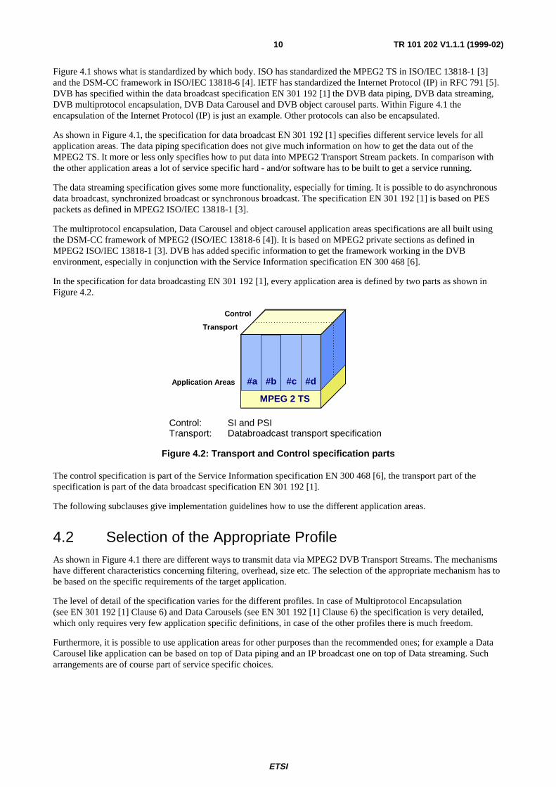

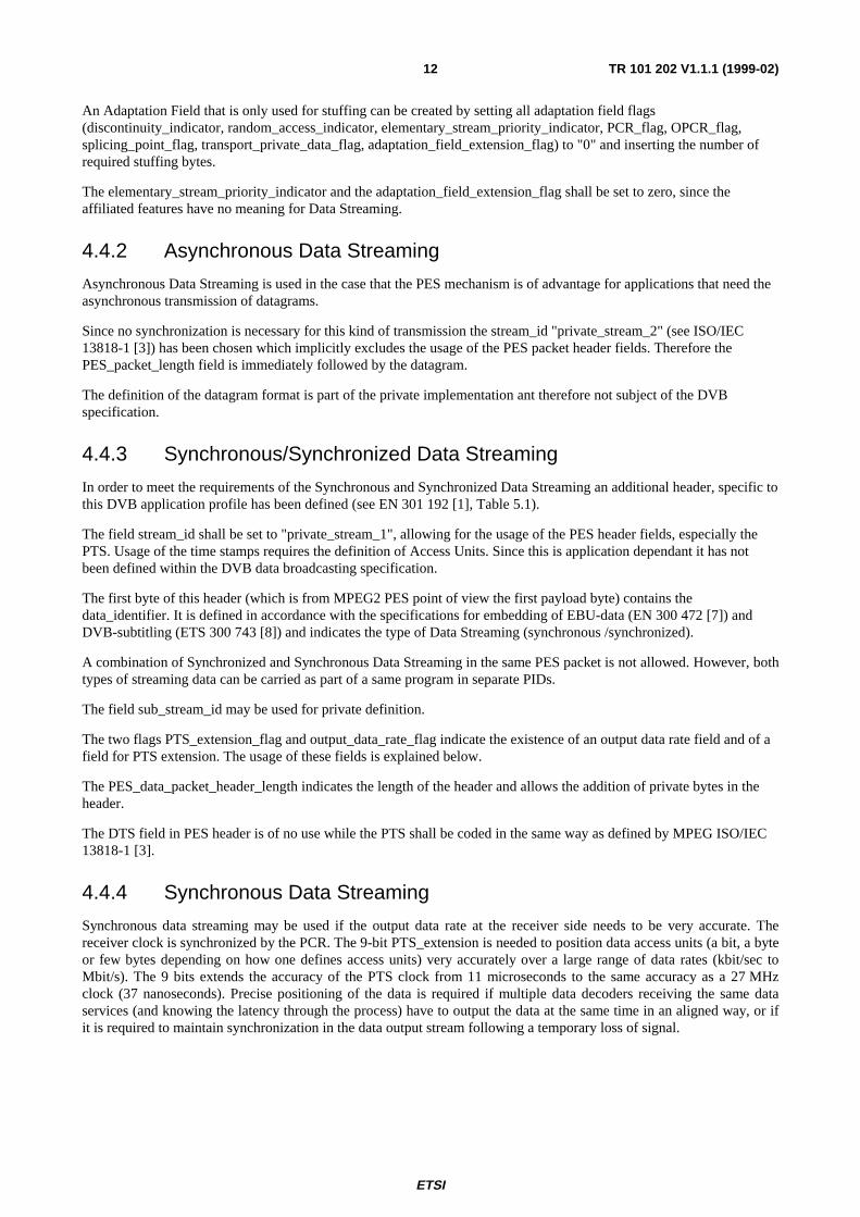

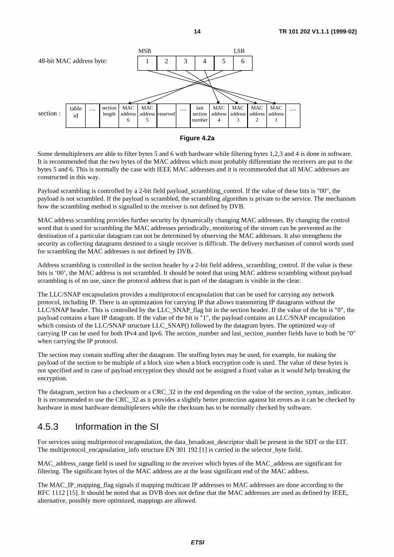


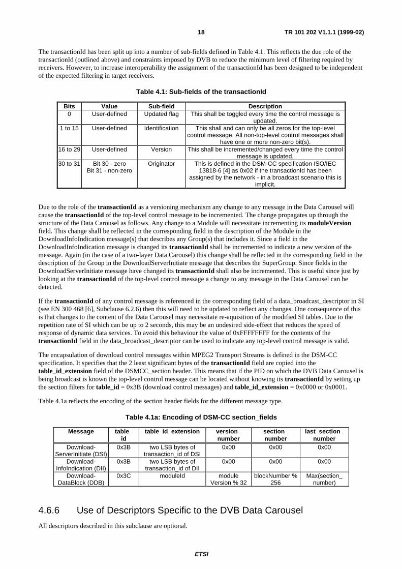


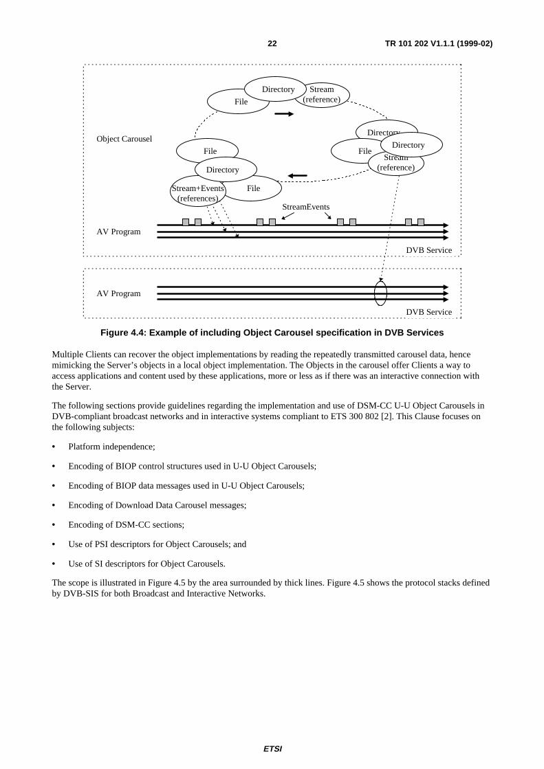
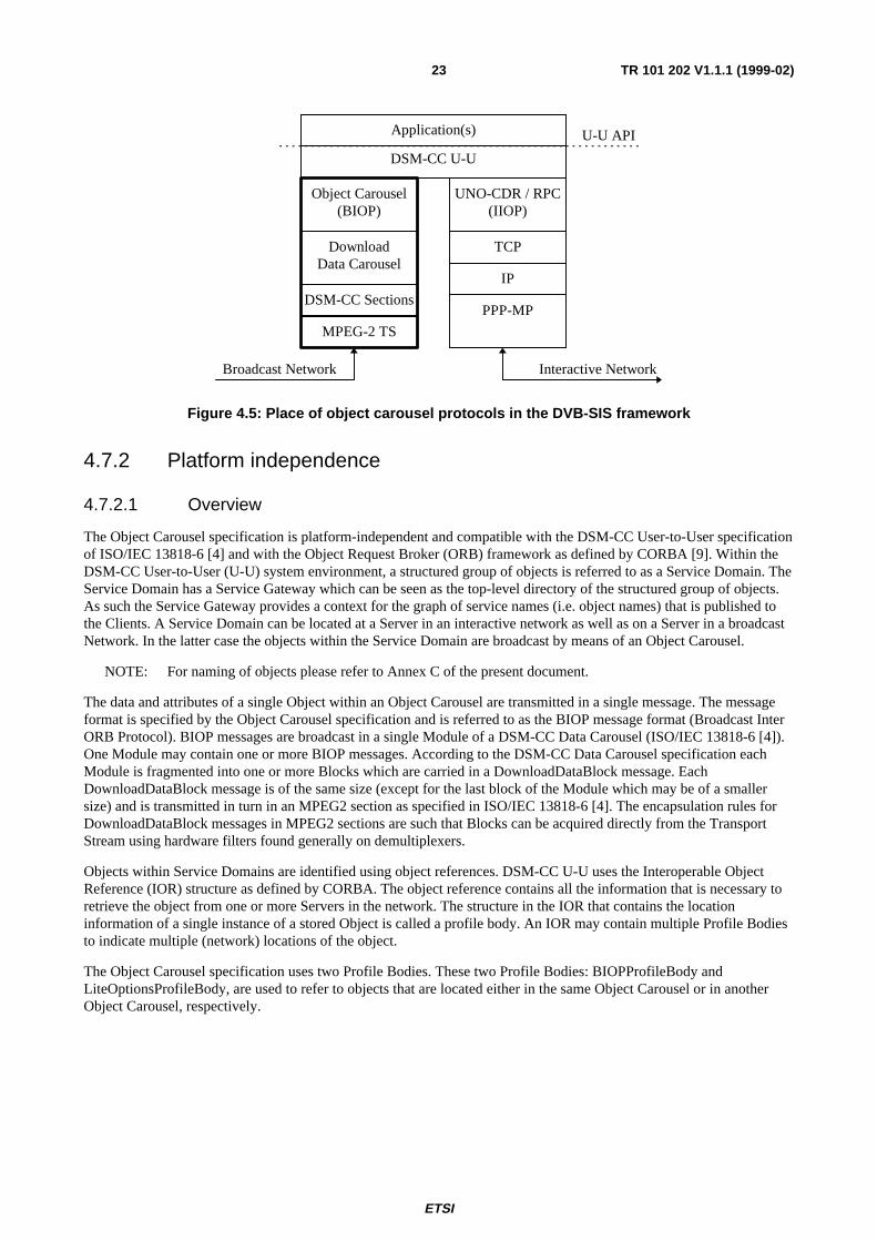


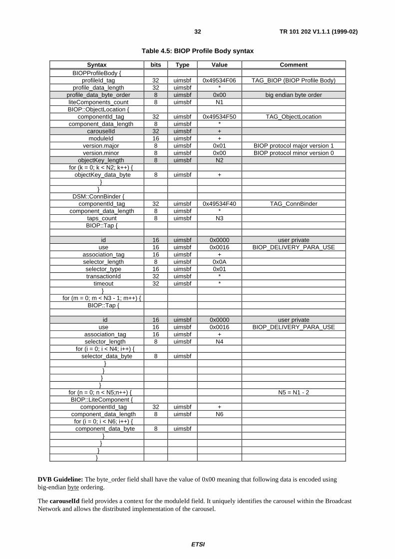


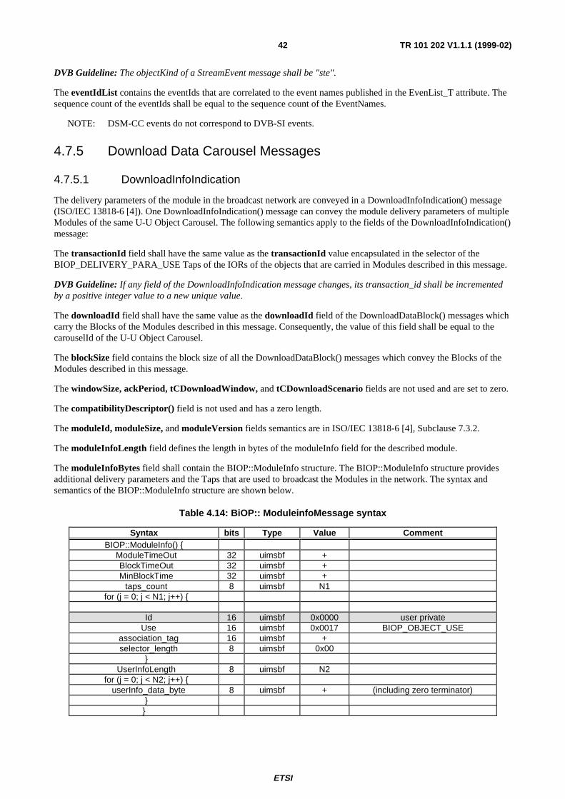

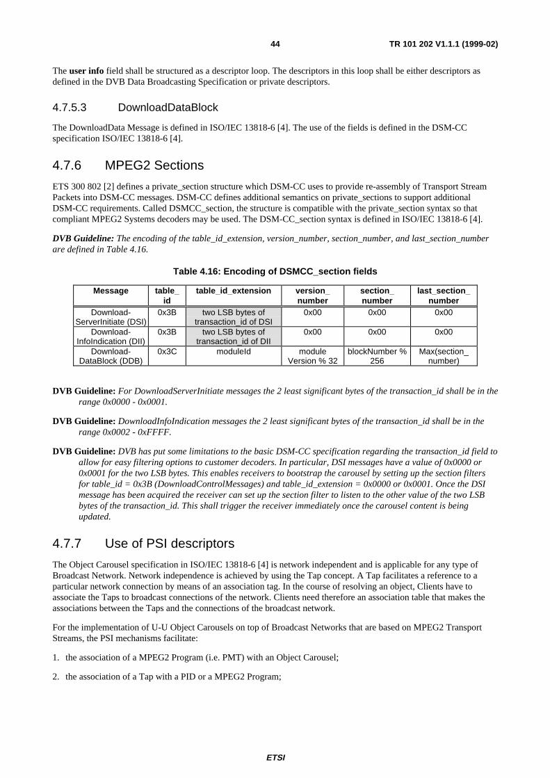


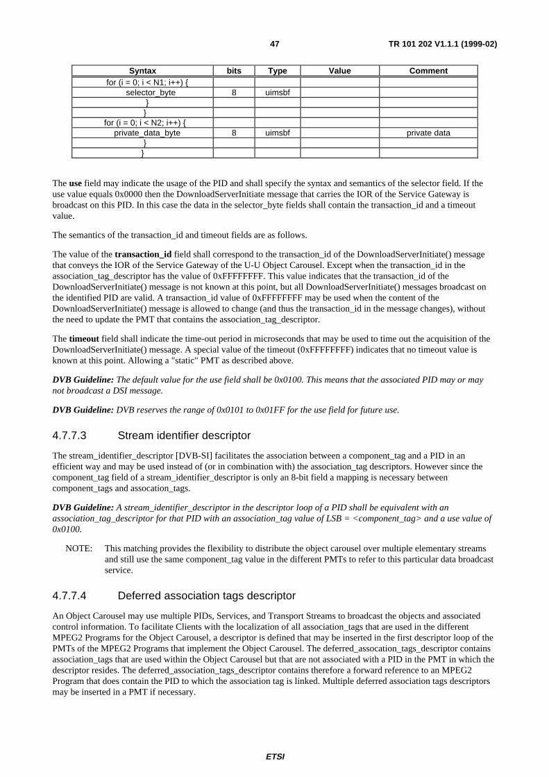

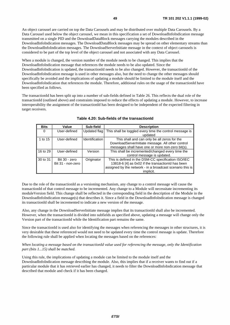


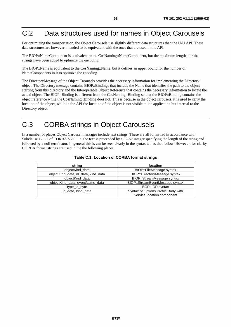


![Digital Video Broadcasting (DVB); Implementation …digitus.itk.ppke.hu/~takacsgy/a147_DVB-C2_Imp-Guide[1].pdfDigital Video Broadcasting (DVB); Implementation Guidelines for a second](https://static.documents.pub/doc/80x56/5fd9ac210e2d412ea673fdfd/digital-video-broadcasting-dvb-implementation-takacsgya147dvb-c2imp-guide1pdf.jpg)


