TR 101 291 V1.1.1 (1998-06) Technical Report Digital Video Broadcasting (DVB); Usage of the DVB test and measurement signalling channel (PID 0x001D) embedded in an MPEG-2 Transport Stream (TS)
Transcript
TR 101 291 V1.1.1 (1998-06)Technical Report
Digital Video Broadcasting (DVB);Usage of the DVB test and measurement signalling channel
(PID 0x001D) embedded in an MPEG-2 Transport Stream (TS)
2 TR 101 291 V1.1.1 (1998-06)
ReferenceDTR/JTC-DVB-81 (byc00ics.PDF)
Keywordsbroadcasting, digital, DVB, TV, video
ETSI
Postal addressF-06921 Sophia Antipolis Cedex - FRANCE
Office address650 Route des Lucioles - Sophia Antipolis
3 Definitions and abbreviations ..................................................................................................................73.1 Definitions ......................................................................................................................................................... 73.2 Abbreviations..................................................................................................................................................... 7
4 Introduction..............................................................................................................................................84.1 Background........................................................................................................................................................ 84.2 Summary of technical requirements................................................................................................................... 8
5 Syntax of PID 0x001D applications.........................................................................................................95.1 Testdata section ................................................................................................................................................. 95.2 Semantic definition of fields in testdata section............................................................................................... 105.3 Definition of subtables..................................................................................................................................... 115.4 Descriptors....................................................................................................................................................... 115.4.1 Descriptor coding....................................................................................................................................... 115.4.2 Elementary id descriptor ............................................................................................................................ 125.4.3 Content information descriptor................................................................................................................... 135.4.4 Source identifier descriptor ........................................................................................................................ 145.4.5 Test signal descriptor ................................................................................................................................. 145.4.6 Time reference descriptor........................................................................................................................... 165.4.7 GPS_descriptor .......................................................................................................................................... 185.4.8 "reduced PCR" descriptor .......................................................................................................................... 185.4.9 program_descriptor .................................................................................................................................... 195.5 Usage of adaptation fields within packets with PID 0x1D............................................................................... 19
Annex A (informative): Detailed description of table content (testdata_byte).................................20
A.1 Network Status Table (NST) .................................................................................................................20A.1.1 Introduction...................................................................................................................................................... 20A.1.2 Functionality .................................................................................................................................................... 20A.1.3 Syntax of the Network Status Table (NST) ..................................................................................................... 20
Annex B (informative): Examples of use for the test packets ............................................................27
B.1 Example of Testdata structure for a measurement table........................................................................27
B.2 Example of Testdata structure for a Testsignal table.............................................................................29
B.3 Example of Testdata structure for a Network Status Table (NST)........................................................31
B.4 Example of Testdata structure for a Reception Status Table (RST)......................................................31
B.5 Example of test data structure for a Remote Control Table (RCT) .......................................................32
Annex C (informative): Examples for data rates ................................................................................36
Intellectual Property RightsIPRs essential or potentially essential to the present document may have been declared to ETSI. The informationpertaining to these essential IPRs, if any, is publicly available for ETSI members and non-members, and can be foundin SR 000 314: "Intellectual Property Rights (IPRs); Essential, or potentially Essential, IPRs notified to ETSI in respectof ETSI standards", which is available free of charge from the ETSI Secretariat. Latest updates are available on theETSI Web server (http://www.etsi.fr/ipr or http://www.etsi.org/ipr).
Pursuant to the ETSI IPR Policy, no investigation, including IPR searches, has been carried out by ETSI. No guaranteecan be given as to the existence of other IPRs not referenced in SR 000 314 (or the updates on the ETSI Web server)which are, or may be, or may become, essential to the present document.
5 TR 101 291 V1.1.1 (1998-06)
ForewordThis Technical Report (TR) has been produced by the Joint Technical Committee (JTC) Broadcast of the EuropeanBroadcasting Union (EBU), Comité Européen de Normalisation ELECtrotechnique (CENELEC) and the EuropeanTelecommunications Standards Institute (ETSI).
NOTE: The EBU/ETSI JTC Broadcast was established in 1990 to co-ordinate the drafting of standards in thespecific field of broadcasting and related fields. Since 1995 the JTC Broadcast became a tripartite bodyby including in the Memorandum of Understanding also CENELEC, which is responsible for thestandardization of radio and television receivers. The EBU is a professional association of broadcastingorganizations whose work includes the co-ordination of its members' activities in the technical, legal,programme-making and programme-exchange domains. The EBU has active members in about 60countries in the European broadcasting area; its headquarters is in Geneva.
European Broadcasting UnionCH-1218 GRAND SACONNEX (Geneva)SwitzerlandTel: +41 22 717 21 11Fax: +41 22 717 24 81
Digital Video Broadcasting (DVB) Project
Founded in September 1993, the DVB Project is a market-led consortium of public and private sector organizations inthe television industry. Its aim is to establish the framework for the introduction of MPEG-2 based digital televisionservices. Now comprising over 200 organizations from more than 25 countries around the world, DVB fostersmarket-led systems, which meet the real needs, and economic circumstances, of the consumer electronics and thebroadcast industry.
6 TR 101 291 V1.1.1 (1998-06)
1 ScopeThe present document proposes a syntax for the test and measurement Packet Identifier PID 0x1D.
2 ReferencesThe following documents contain provisions which, through reference in this text, constitute provisions of the presentdocument.
• References are either specific (identified by date of publication, edition number, version number, etc.) ornon-specific.
• For a specific reference, subsequent revisions do not apply.
• For a non-specific reference, subsequent revisions do apply.
• A non-specific reference to an ETS shall also be taken to refer to later versions published as an EN with the samenumber.
[1] ISO/IEC 13818-1: "Information technology - Generic coding of moving pictures and associatedaudio information: Systems".
[2] EN 300 468: "Digital Video Broadcasting (DVB); Specification for Service Information (SI) inDVB systems".
[3] ETR 290: "Digital Video Broadcasting (DVB); Measurement guidelines for DVB systems".
[4] EN 300 429: "Digital Video Broadcasting (DVB); Framing structure, channel coding andmodulation for cable systems".
[5] EN 300 421: "Digital Video Broadcasting (DVB); Framing structure, channel coding andmodulation for 11/12 GHz satellite services".
[6] EN 300 744: "Digital Video Broadcasting (DVB); Framing structure, channel coding andmodulation for digital terrestrial television".
[7] ISO/IEC 639-2: "Codes for the representation of names of languages -- Part 2: Alpha-3 code".
[8] ISO/IEC 8859-1: "Information processing - 8-bit single-byte coded graphic character sets - Part 1:Latin alphabet No. 1".
7 TR 101 291 V1.1.1 (1998-06)
The syntax of the Testdata contained in PID 0x001D is based on the structure of the Private section as defined inISO/IEC 13818-1 [1].
A testdata table may be made of several testdata sections. Different testdata tables (for different applications) arespecified by their table_id and table_id_extension values.
One testdata table shall have only one priority level, so only complete tables may be replaced or removed.
The values for structure elements "table_id" and "descriptor_tag" may be user defined as specified in ISO/IEC 13818-1[1].
In the PSI PMT table, the use of a specific descriptor would allow to precise if, for a given elementary stream, there iscorresponding test data in the PID 0x1D stream.
3 Definitions and abbreviations
3.1 DefinitionsFor the purposes of the present document, the following definitions apply:
MPEG-2: refers to the standard ISO/IEC 13818 [1]. Systems coding is defined in part 1. Video coding is defined inpart 2. Audio coding is defined in part 3.
multiplex: a stream of all the digital data carrying one or more services within a single physical channel.
Service Information (SI): digital data describing the delivery system, content and scheduling/timing of broadcast datastreams etc. It includes MPEG-2 PSI together with independently defined extensions.
Transport Stream (TS): a TS is a data structure defined in ISO/IEC 13818-1 [1]. It is the basis of the ETSI DigitalVideo Broadcasting (DVB) standards.
3.2 AbbreviationsFor the purposes of the present document, the following abbreviations apply:
BER Bit Error Ratebslbf bit string, left bit firstCRC Cyclic Redundancy CheckCW Continuous WaveDVB Digital Video BroadcastingDVB-C Digital Video Broadcasting baseline system for digital cable television (EN 300 429)DVB-S Digital Video Broadcasting baseline system for digital satellite television (EN 300 421)DVB-T Digital Video Broadcasting baseline system for digital terrestrial television (EN 300 744)EB Errored BlockES Errored SecondEIT Encoded Information TypeETR ETSI Technical ReportETS European Telecommunication StandardIEC International Electrotechnical CommissionIRD Integrated Receiver DecoderISO International Organisation for StandardisationMMDS Microwave Multi-point Distribution Systems (or Multichannel Multi-point Distribution Systems)MPEG Moving Picture Experts GroupMPTS Multiple Presentation Time StampsMVDS Multi-point Video Distribution SystemsNIT Network Information TableNST Network Status TablePCR Program Clock ReferencePID Packet Identifier
8 TR 101 291 V1.1.1 (1998-06)
PTS Presentation Time StampsQEF Quasi Error Freer.m.s root mean squareRS Reed SolomonSDP Severely Disturbed PeriodSDT Service Description TableSES Seriously Errored SecondSFN Single Frequency NetworkSPTS Multiple Presentation Time StampsTDT Target Designation TransmitterTS Transport StreamTV TelevisionUI Unit Intervaluimsbf unsigned integer, most significant bit firstUTC Universal Time Co-ordinated
4 Introduction
4.1 BackgroundThe Digital Video Broadcasting (DVB) set of digital TV standards specify baseline systems for various transmissionmedia: satellite, cable, terrestrial, etc. Each baseline system standard defines the channel coding and modulationschemes for that transmission medium. The source coding adopted was from the MPEG-2 standard.
The design of these new systems has created a demand for a common understanding of measurement techniques and theinterpretation of measurement results, this led to the introduction of the "DVB Measurement Guidelines" ETR 290 [3].
The deployment of complex digital broadcasting network architectures raised the following requirements:
• In order to make the test data independent of any PSI / SI table within a TS and to allow the packets to be freelydefined without disturbing any current equipment, a specific PID from the DVB reserved range has been assigned.The number assigned was 0x1D.
• Test data may be inserted into an existing TS by replacing null packets with packets containing the test data with theassignment PID 0x1D. Alternatively test data may be introduced via a multiplexer in which case it is at the discretionof the multiplex operator to assign sufficient bandwidth to PID 0x1D. Annex A provides an indication of the likelybandwidth requirements for various applications.
4.2 Summary of technical requirementsThe chosen solution allows for the following requirements:
- technical compatibility with MPEG / DVB standards to ensure that existing equipment will continue to work withtransport streams containing PID 0x1D. This will also enable potential reduction of development effort to enablefull support of PID 0x1D applications in future equipment implementations;
- support for all currently identified application areas;
- the provision should be made for user defined solutions to meet the private needs of network operators;
- simplification of the test data inserter and test data removal equipment;
- prioritization of test data to allow end-to-end communication across a network or the re-use of test data capacitywithin a network as appropriate to the application. The prioritization of test data packets shall allow theirtransmission within a network or across network operator borders.
9 TR 101 291 V1.1.1 (1998-06)
5 Syntax of PID 0x001D applicationsAll table_ids and descriptor_tags defined in the present document are only valid in the context of packets with PID0x1D.
5.1 Testdata sectionTable 1 defines the structure for testdata sections, transmitted in transport streams with PID 0x001D.
Table 1: Testdata section
Syntax No. of bits Mnemonictestdata_section() {
table_id 6 uimsbf
priority_level 2 uimsbf
section_syntax_indicator 1 bslbf
reserved 3 bslbf
testdata_section_length 12 uimsbf
if (section_syntax_indicator == 0) {for (i=0; i< test_data_section_length; i++){
5.2 Semantic definition of fields in testdata sectiontable_id: This is a 6-bit field, the value of which identifies the type of testdata table this section belongs to (see alsotable 3).
NOTE: When using the PID 0x1D, the table_id can be chosen from the whole range except the values reserved byMPEG. If the concept is implemented under another PID, further constraints for the choice of table_idhave to be considered.
priority_level: This 2-bit field will be used for priority handling as specified in table 2.
Table 2: Priority levels and description
Priority Level Description0x00 low_priority, single hop testing, either transport or distribution
0x01 medium_priority, multiple hop testing, either transport or distribution
0x02 high_priority, transport path tests only, no distribution paths
0x03 super_priority, end-to-end testing, including both
section_syntax_indicator: When set to 1, it indicates that the testdata section follows the generic section syntax beyondthe testdata_section_length field. When set to "0", it indicates that the testdata_bytes immediately follow thetestdata_section_length field.
reserved: This 3 bits shall all be set to 1.
testdata_section_length: A 12-bit field. It specifies the number of remaining bytes in the testdata section immediatelyfollowing the testdata_section_length field up to the end of the testdata_section. The value in this field shall not exceed4 093.
user_defined: This 8-bit field is user defined and may be used for any purpose.
table_id_extension: This 8-bit field is used for the table_id_extension. Use and values are defined as specified intable 3. The values 0x00 and 0xFF are reserved for future use.
version_number: This 5-bit field is the version number of the testdata_section. The version_number shall beincremented by 1 modulo 32 when a change in the information carried within the testdata_section occurs.
current_next_indicator: A 1-bit field, which shall be set to 1.
section_number: This 8-bit field gives the number of the testdata_section. The section_number of the first section in atestdata table shall be 0x00. The section_number shall be incremented by 1 modulo 256 with each additional section inthis testdata table.
last_section_number: This 8-bit field specifies the number of the last section (that is, the section with the highestsection_number) of the testdata table of which this section is a part.
reserved: 4 bits which shall be set to "0".
descriptors_length: A 12-bit field. It specifies the number of bytes in the descriptors immediately following thedescriptors_length field up to the start of Testdata bytes. The value in this field shall not exceed 4 082. The number ofdescriptors is user definable and can be zero or more.
descriptor: See table 4 for list of predefined descriptors. Users may add their own descriptors, where descriptor_tagsshall not be used twice.
testdata_byte: One or more testdata bytes, to be defined. Informative examples for structures of testdata bytes are givenin clause 5 at the end of the present document.
11 TR 101 291 V1.1.1 (1998-06)
CRC_32: This is a 32-bit field that contains the CRC value that gives a zero output of the registers in the decoderdefined in annex B of ISO/IEC 13818-1 [1] after processing the entire testdata section.
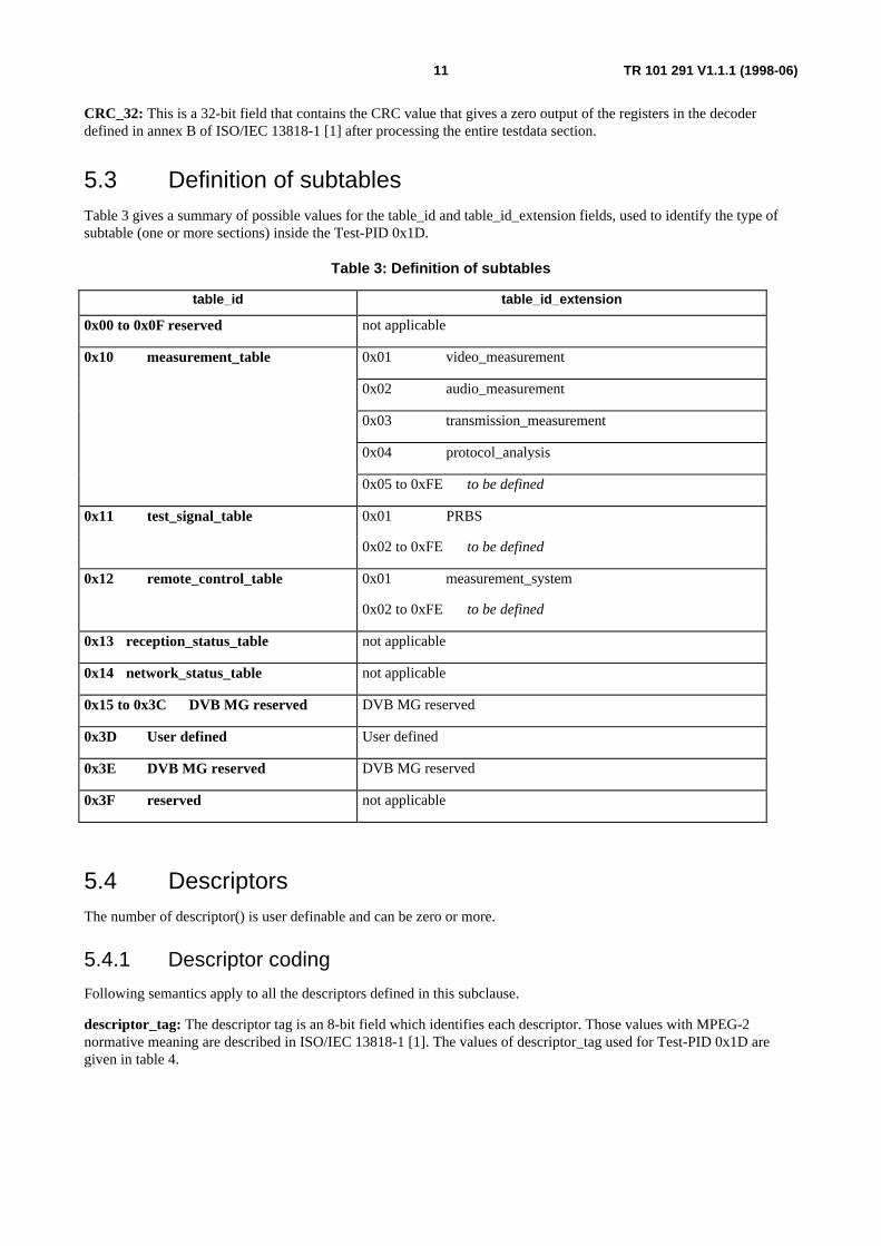
5.3 Definition of subtablesTable 3 gives a summary of possible values for the table_id and table_id_extension fields, used to identify the type ofsubtable (one or more sections) inside the Test-PID 0x1D.
Table 3: Definition of subtables
table_id table_id_extension
0x00 to 0x0F reserved not applicable
0x10 measurement_table 0x01 video_measurement
0x02 audio_measurement
0x03 transmission_measurement
0x04 protocol_analysis
0x05 to 0xFE to be defined
0x11 test_signal_table 0x01 PRBS
0x02 to 0xFE to be defined
0x12 remote_control_table 0x01 measurement_system
0x02 to 0xFE to be defined
0x13 reception_status_table not applicable
0x14 network_status_table not applicable
0x15 to 0x3C DVB MG reserved DVB MG reserved
0x3D User defined User defined
0x3E DVB MG reserved DVB MG reserved
0x3F reserved not applicable
5.4 DescriptorsThe number of descriptor() is user definable and can be zero or more.
5.4.1 Descriptor coding
Following semantics apply to all the descriptors defined in this subclause.
descriptor_tag: The descriptor tag is an 8-bit field which identifies each descriptor. Those values with MPEG-2normative meaning are described in ISO/IEC 13818-1 [1]. The values of descriptor_tag used for Test-PID 0x1D aregiven in table 4.
12 TR 101 291 V1.1.1 (1998-06)
Table 4: Descriptor identification
Descriptor Tag Valueelementary_id_descriptor 0x40
content_information_descriptor 0x41
source_identifier_descriptor 0x42
test_signal_descriptor 0x43
time_reference_descriptor 0x44
GPS_descriptor 0x45
reduced_PCR_descriptor 0x46
program_descriptor 0x47
to be defined 0x48 to 0xFE
descriptor_length: The descriptor length is an 8-bit field specifying the total number of data bytes of the descriptorimmediately following the descriptor_length field.
5.4.2 Elementary id descriptor
Table 5: elementary_id_descriptor
Syntax No. of bits Mnemonicelementary_id_descriptor() {
descriptor_tag 8 uimsbf
descriptor_length 8 uimsbf
id_type 3 uimsbf
if (id_type <= 3) {
elementary_stream_PID 13 uimsbf
}
else {
reserved_for_future_use 13 uimsbf
}
}
13 TR 101 291 V1.1.1 (1998-06)
id_type: A 3-bit field. A value of lower than or equal to 3 indicates that the following datafield contains the PID of anelementary stream, for which measurement values (Video or Audio) are available (see table 5A). Values 0x4 to 0x7 arereserved for future use.
Table 5A
id_type Value
0x0 user defined
0x1 for video stream
0x2 for audio stream
0x3 for data stream
0x4 to 0x7 reserved for future use
elementary_stream_PID: A 13-bit field, which contains the PID of an elementary stream, for which measurementvalues (Video or Audio) are available. The value 0x1FFF is forbidden (PID of null packets).
reserved_for_future_use: A 13-bit field, which shall be set to 0x1FFF.
5.4.3 Content information descriptor
Table 6: content_information_descriptor
Syntax No. of bits Mnemoniccontent_information_descriptor() {
descriptor_tag 8 uimsbf
descriptor_length 8 uimsbf
ISO_639_language_code 24 uimsbf
for (i=0; i<N; i++) {
text_char 8 uimsbf
}
}
ISO_639_language_code: This 24-bit field contains the ISO/IEC 639-2 [7] three character language code of thelanguage of the following content information. Both ISO 639-2/B or ISO 639-2/T may be used. Each character is codedinto 8 bits according to ISO/IEC 8859-1 [8] and inserted into the 24-bit field.
EXAMPLE: French has 3 character code "fre", which is coded as "0110 0110 0111 0010 0110 0101"
text_char: This is an 8-bit field. The string of character fields is user definable and has to be coded using character setsand methods described in annex A of EN 300 468 [2].
14 TR 101 291 V1.1.1 (1998-06)
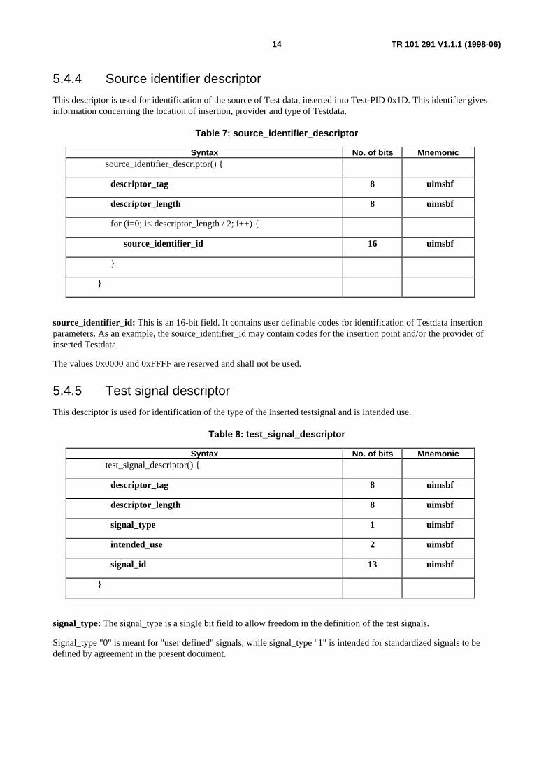
5.4.4 Source identifier descriptor
This descriptor is used for identification of the source of Test data, inserted into Test-PID 0x1D. This identifier givesinformation concerning the location of insertion, provider and type of Testdata.
Table 7: source_identifier_descriptor
Syntax No. of bits Mnemonicsource_identifier_descriptor() {
descriptor_tag 8 uimsbf
descriptor_length 8 uimsbf
for (i=0; i< descriptor_length / 2; i++) {
source_identifier_id 16 uimsbf
}
}
source_identifier_id: This is an 16-bit field. It contains user definable codes for identification of Testdata insertionparameters. As an example, the source_identifier_id may contain codes for the insertion point and/or the provider ofinserted Testdata.
The values 0x0000 and 0xFFFF are reserved and shall not be used.
5.4.5 Test signal descriptor
This descriptor is used for identification of the type of the inserted testsignal and is intended use.
Table 8: test_signal_descriptor
Syntax No. of bits Mnemonictest_signal_descriptor() {
descriptor_tag 8 uimsbf
descriptor_length 8 uimsbf
signal_type 1 uimsbf
intended_use 2 uimsbf
signal_id 13 uimsbf
}
signal_type: The signal_type is a single bit field to allow freedom in the definition of the test signals.
Signal_type "0" is meant for "user defined" signals, while signal_type "1" is intended for standardized signals to bedefined by agreement in the present document.
15 TR 101 291 V1.1.1 (1998-06)
Table 9: Test signal_id table (for signal_type=0)
Value Description0x0000 reserved
0x0001 to 0x1FFE User defined
0x1FFF reserved
Table 10: Test signal_id table (for signal_type=1)
Value Description0x000 reserved
0x001 Time Reference
0x002 PRBS #1
0x003 Pathological 1, Reverse of the energy dispersal for all "ones"
0x004 Pathological 2, Reverse of the energy dispersal for all "zeroes"
0x005 Pathological 3, Reverse of the energy dispersal for 8 pakets of all "ones" followed by8 packets of all "zeroes".
··· Future use
0x3FF reserved
signal_id: The signal_id is a fixed 13 bit field indicating the type of test signal. Up to 8 192 different test signals can bedefined in each of the two types of signals.
Table 11: Intended use table
Value Description00 Undefined
01 In-service measurements
10 Out-of-service measurements
11 Both
intended_use: The intended_use is a two bit field used as an indicator of the appropriate use of the signal.
16 TR 101 291 V1.1.1 (1998-06)
5.4.6 Time reference descriptor
This descriptor can be used as a reference for all test equipment to measure delays in the signal path.
Table 12: time_reference_descriptor
Syntax No. of bits Mnemonictime_reference_descriptor() {
descriptor_tag 8 uimsbf
descriptor_length 8 uimsbf
reference_type 6 uimsbf
precision_range 2 uimsbf
UTC_time 40 uimsbf
if (precision_range ==1) {
reserved 6 uimsbf
millisecond_extension 10 uimsbf
}
if (precision_range ==2) {
reserved 4 uimsbf
millisecond_extension 10 uimsbf
microsecond_extension 10 uimsbf
}
if (precision_range ==3) {
reserved 2 uimsbf
millisecond_extension 10 uimsbf
microsecond_extension 10 uimsbf
nanosecond_extension 10 uimsbf
}
reference_type: This 6-bit field indicates the nature of the reference clock, so the receiver can contrast what is the bestfit for the measurement. The use of a XCO (value 0), could not provide a good enough absolute time reference, howeverstill can be an option of the test generator for measurements of delay in close loop systems, such as a terrestrialtransmitter and a terrestrial reference receiver measured by a test generator-analyzer equipment used for transmitterdelay measurements.
17 TR 101 291 V1.1.1 (1998-06)
Table 13: Reference_type table
Value Description0 Internal XCO of the test generator
1 GPS grade 1
2 GPS grade 2
3 Timing Reference Radio Station
4 Future use
5 Future use
6 1x10⁻⁶
7 1x10⁻⁷
8 1x10⁻⁸
9 1x10⁻⁹
10 1x10⁻¹⁰
11 1x10-11
12 1x10-12
... Future use
63 Future use
precision_range: A 2-bit field indicating the precision of the time reference used.
UTC_time: This 40-bit field contains the current time and date in UTC and MJD (see annex C of EN 300 468 [2]). Thisfield is coded as 16 bits giving the 16 LSBs of MJD followed by 24 bits coded as 6 digits in 4-bit BCD.
millisecond_extension: This 10-bit field should contain a binary number indicating the number of milliseconds.
microsecond_extension: This 10-bit field should contain a binary number indicating the number of microseconds.
nanosecond_extension: This 10-bit field should contain a binary number indicating the number of nanoseconds.
NOTE: In GPS applications, the 10 MHz reference signal can be used for the generation of the time extension.The resolution of the extension should be given up to the nanosecond, however the increment can be madeto tens of nanosecond or hundreds of nanosecond, depending on the reference accuracy.
18 TR 101 291 V1.1.1 (1998-06)
5.4.7 GPS_descriptor
Table 14: GPS_descriptor
Syntax No. of bits MnemonicGPS_descriptor() {
descriptor_tag 8 uimsbf
descriptor_length 8 uimsbf
north_south 1 uimsbf
geo_latitude 23 uimsbf
east_west 1
geo_longitude 23 uimsbf
geo_elevation 16 uimsbf
}
NOTE: This table may have to be reviewed.
5.4.8 "reduced PCR" descriptor
When the "reduced PCR" descriptor is inserted in a table which contains a "time_reference_descriptor", the followingassumption is made.
The "reduced PCR" field conveys the 32 most significant bits of the PCR_base, referring to the TS packet arriving at theinstant at which the time_reference field is derived from the timing reference.
Table 15: reduced_PCR descriptor
Syntax No. of bits Mnemonicreduced_PCR_descriptor() {
descriptor_tag 8 uimsbf
descriptor_length 8 uimsbf
reduced_PCR_base 32 uimsbf
}
19 TR 101 291 V1.1.1 (1998-06)
5.4.9 program_descriptor
The program number and the PID number of the PMT can be indicated before "elementary_id_descriptor". Thus, theapplication can find easily complementary information in PSI/SI if needed.
Table 16: program_descriptor
Syntax No. of bits Mnemonicprogram_descriptor() {
descriptor_tag 8 uimsbf
descriptor_length 8 uimsbf
program_number 16 uimsbf
reserved 3 uimsbf
program_map_pid 13 uimsbf
}
5.5 Usage of adaptation fields within packets with PID 0x1DMany applications using the packets with PID 0x1D will use no adaptation_field, payload only(adaptation_field_control = "01"). Some applications however will use adaptation_field only, no payload(adaptation_field_control = "10"). In this case, the first 4 bytes of the adaptation field should follow the syntax of theTransport Stream adaptation field (table 2-7 of ISO/IEC 13818-1 [1]) but with all indicators and flags set to "zero" withthe exception of the transport_private_data_flag which shall be set to "one".
The first private_data_byte of the adaptation field of each packet shall be an exact copy of the table_id (6 bits) followedby the priority level (2 bits) as defined above in table 1 (test data section). The remaining 180 bytes, fromsection_syntax_indicator to CRC32, constitute the data bytes for all the table_id defined in table 3 with the exception oftable_id = 0x3E which may be defined by DVB MG for future use.
By using this adaptation field, the type of application, as well as the priority level will be present in each test packet andwill allow for individual processing of each packet reducing delays and memory buffers.
When adaptation_field_control = "10", Packet Unit Start Indicator shall be "1" if the transport packet carries thebeginning of a test_data_section which can be distinguished by the following sequence: byte "table_id / priority_level",followed by 2 bytes "section_syntax_indicator / reserved / test_data_section_length".
20 TR 101 291 V1.1.1 (1998-06)
Annex A (informative):Detailed description of table content (testdata_byte)
A.1 Network Status Table (NST)
A.1.1 IntroductionIn a digital broadcast environment with a multitude of services there is a need for highly automated means to monitorand subsequently to provide information (e.g. failure messages) about the availability of equipment and services as wellas of service components such as video, audio and subtitling and of Service Information (SI) tables.
In order to support the detection of service and equipment failures, to provide information for remedial measures and toefficiently log such events, a transport mechanism, the Network Status Table (NST) has been defined. This system willserve for conveying diagnostic information about the consistency of all DVB/MPEG-2 multiplexes within a network.
A.1.2 FunctionalityNSTs can be generated at any point in the transmission chain to signal missing streams (e.g. video, audio, subtitle oraccompanied data) or Service Information components (e.g. NIT, SDT, EIT or TDT) within a multiplex. As theunderlying concept of the NST system is to detect and signal failures at the point where they are generated, the systemsupervisor of the DVB/MPEG-2 encoding, multiplexing and modulation equipment should monitor the correctfunctioning of all equipment modules and should generate an NST in the case a service failure occurs for longer than10 seconds.
NSTs shall then be periodically transmitted every 10 seconds until the failure is fixed. In addition to faulty equipmentmodules also missing input streams can be identified by subsequent modules in the transmission chain which thengenerate corresponding NSTs.
A.1.3 Syntax of the Network Status Table (NST)The syntax of the NST is conforming to the one defined in the standard ISO/IEC 13818-1 [1] for the definition ofprivate sections.
The Network Status Table shall be carried on PID 0x001D using the normal payload_unit_start_indicator/pointer fieldmechanism described in the standard ISO/IEC 13818-1 [1]. A NST shall be inserted in maximum one Transport Streampacket resulting in a maximum table size of 183 bytes.
21 TR 101 291 V1.1.1 (1998-06)
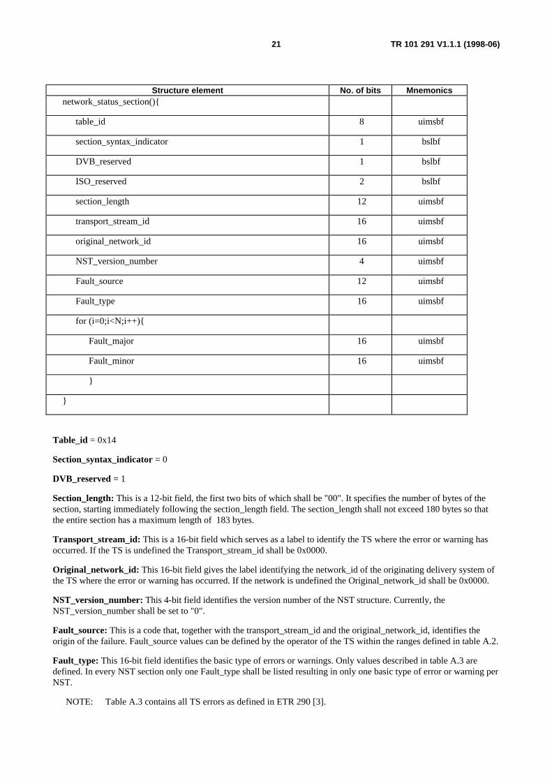
Structure element No. of bits Mnemonicsnetwork_status_section(){
table_id 8 uimsbf
section_syntax_indicator 1 bslbf
DVB_reserved 1 bslbf
ISO_reserved 2 bslbf
section_length 12 uimsbf
transport_stream_id 16 uimsbf
original_network_id 16 uimsbf
NST_version_number 4 uimsbf
Fault_source 12 uimsbf
Fault_type 16 uimsbf
for (i=0;i<N;i++){
Fault_major 16 uimsbf
Fault_minor 16 uimsbf
}
}
Table_id = 0x14
Section_syntax_indicator = 0
DVB_reserved = 1
Section_length: This is a 12-bit field, the first two bits of which shall be "00". It specifies the number of bytes of thesection, starting immediately following the section_length field. The section_length shall not exceed 180 bytes so thatthe entire section has a maximum length of 183 bytes.
Transport_stream_id: This is a 16-bit field which serves as a label to identify the TS where the error or warning hasoccurred. If the TS is undefined the Transport_stream_id shall be 0x0000.
Original_network_id: This 16-bit field gives the label identifying the network_id of the originating delivery system ofthe TS where the error or warning has occurred. If the network is undefined the Original_network_id shall be 0x0000.
NST_version_number: This 4-bit field identifies the version number of the NST structure. Currently, theNST_version_number shall be set to "0".
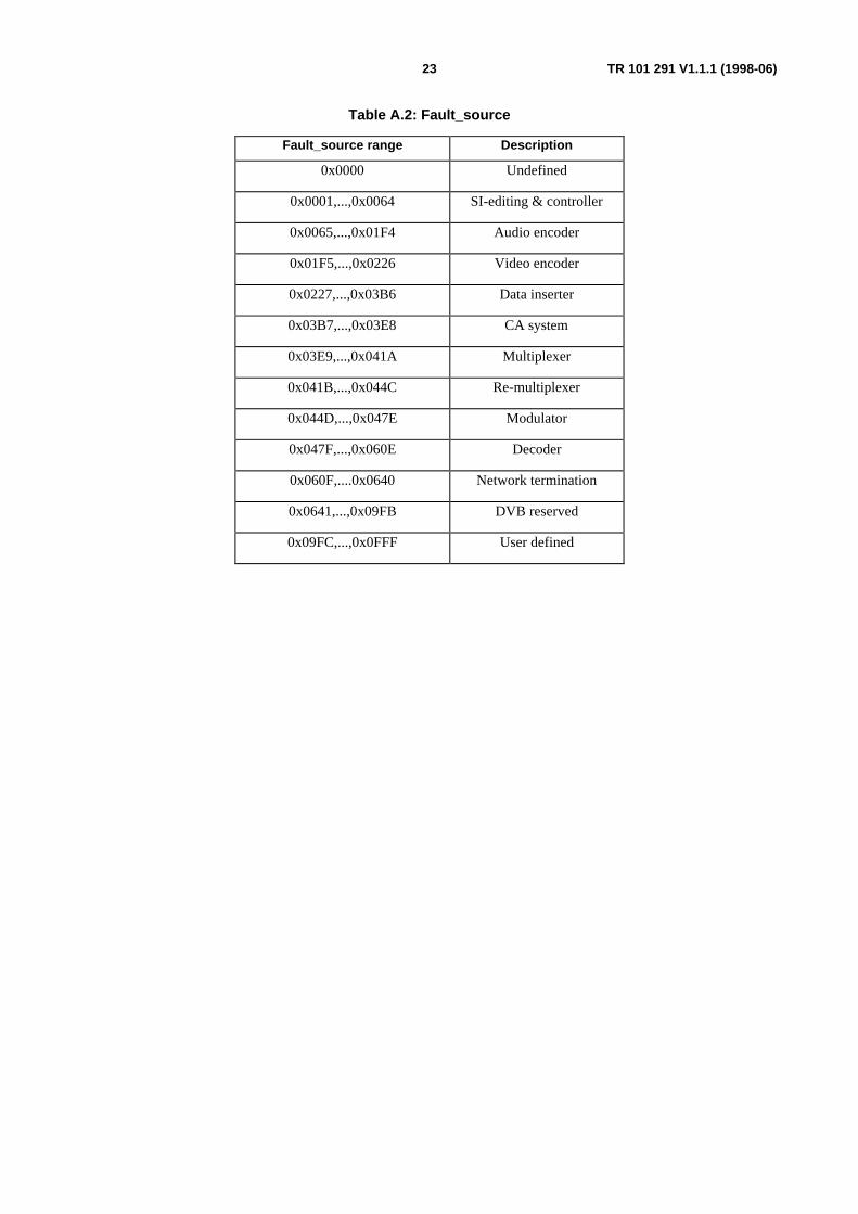
Fault_source: This is a code that, together with the transport_stream_id and the original_network_id, identifies theorigin of the failure. Fault_source values can be defined by the operator of the TS within the ranges defined in table A.2.
Fault_type: This 16-bit field identifies the basic type of errors or warnings. Only values described in table A.3 aredefined. In every NST section only one Fault_type shall be listed resulting in only one basic type of error or warning perNST.
NOTE: Table A.3 contains all TS errors as defined in ETR 290 [3].
22 TR 101 291 V1.1.1 (1998-06)
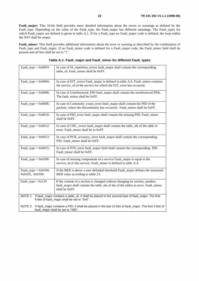
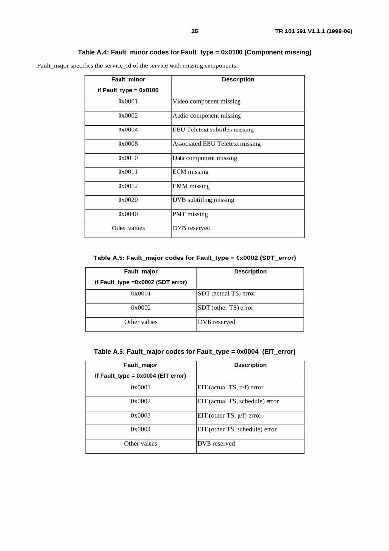
Fault_major: This 16-bit field provides more detailed information about the errors or warnings as defined by theFault_type. Depending on the value of the Fault_type, the Fault_major has different meanings. The Fault_types forwhich Fault_major are defined is given in table A.1. If for a Fault_type no Fault_major code is defined, the loop withinthe NST shall be empty.
Fault_minor: This field provides additional information about the error or warning as described by the combination ofFault_type and Fault_major. If no Fault_minor code is defined for a Fault_major code, the Fault_minor field shall bepresent and all bits shall be set to "1".
Table A.1: Fault_major and Fault_minor for different Fault_types
Fault_type = 0x0003: In case of SI_repetition_errors fault_major shall contain the correspondingtable_id. Fault_minor shall be 0xFF.
Fault_type = 0x0004: In case of EIT_errors Fault_major is defined in table A.6. Fault_minor containsthe service_id of the service for which the EIT_error has occurred.
Fault_type = 0x0006: In case of Unreferenced_PID fault_major shall contain the unreferenced PIDs.The fault_minor shall be 0xFF.
Fault_type = 0x000E: In case of Continuity_count_error fault_major shall contain the PID of thepackets, where the discontinuity has occurred. Fault_minor shall be 0xFF.
Fault_type = 0x0010: In case of PID_error fault_major shall contain the missing PID. Fault_minorshall be 0xFF.
Fault_type = 0x0012: In case of CRC_errors fault_major shall contain the table_ids of the table inerror. Fault_minor shall be to 0xFF
Fault_type = 0x0013: In case of PCR_accuracy_error fault_major shall contain the correspondingPID. Fault_minor shall be 0xFF.
Fault_type = 0x0015: In case of PTS_error fault_major field shall contain the corresponding PID.Fault_minor shall be 0xFF.
Fault_type = 0x0100: In case of missing components of a service Fault_major is equal to theservice_id of this service. Fault_minor is defined in table A.4.
Fault_type = 0x0104,0x0105, 0x0106:
If the BER is above a user definded threshold Fault_major defines the measuredBER value according to table 23.
Fault_type = 0x110 If the content of a section is changed without changing its version_number,fault_major shall contain the table_ids of the of the tables in error. Fault_minorshall be 0xFF.
NOTE 1: If fault_major contains a table_id, it shall be placed in the second byte of fault_major. The first8 bits of fault_major shall be set to "0x0".
NOTE 2: If fault_major contains a PID, it shall be placed in the last 13 bits of fault_major. The first 3 bits offault_major shall be set to "000".
23 TR 101 291 V1.1.1 (1998-06)
Table A.2: Fault_source
Fault_source range Description
0x0000 Undefined
0x0001,...,0x0064 SI-editing & controller
0x0065,...,0x01F4 Audio encoder
0x01F5,...,0x0226 Video encoder
0x0227,...,0x03B6 Data inserter
0x03B7,...,0x03E8 CA system
0x03E9,...,0x041A Multiplexer
0x041B,...,0x044C Re-multiplexer
0x044D,...,0x047E Modulator
0x047F,...,0x060E Decoder
0x060F,....0x0640 Network termination
0x0641,...,0x09FB DVB reserved
0x09FC,...,0x0FFF User defined
24 TR 101 291 V1.1.1 (1998-06)
Table A.3: Fault_type
Fault_type Description
0x0000 Undefined
0x0001 NIT_error (No. 3.1)
0x0002 SDT_error (No. 3.5)
0x0003 SI_repetition_error (No. 3.2)
0x0004 EIT_error (No. 3.6)
0x0005 Buffer_error (No. 3.3)
0x0006 Unreferenced_PID (No. 3.4)
0x0007 Empty_buffer_error (No. 3.9)
0x0008 TDT_error (No. 3.8)
0x0009 PAT_error (No. 1.3)
0x000A CAT_error (No. 2.6)
0x000B Data_delay_error (No. 3.10)
0x000C TS_sync_loss (No. 1.1)
0x000D Sync_byte_error (No. 1.2)
0x000E Continuity_count_error (No. 1.4)
0x000F PMT_error (No. 1.5)
0x0010 PID_error (No. 1.6)
0x0011 Transport_error (No. 2.1)
0x0012 CRC_error (No. 2.2)
0x0013 PCR_error (No. 2.3)
0x0014 PCR_accuracy_error (No. 2.4)
0x0015 PTS_error (No. 2.5)
0x0016 RST_error (No. 3.7)
0x0020 TSDT_error (for DSNG)
0x0060 Input signal missing
0x0080 Transport Stream missing
0x0100 Component of service missing
0x0104 BER before Viterbi above threshold
0x0105 BER before RS above threshold
0x0106 BER after RS above threshold
0x0110 PSI/SI section modified without changing the version_number
Other fault_type <= 0x0800 DVB reserved
Fault_type > 0x0800 User defined
NOTE: The numbers in bracket specify the corresponding TS error as defined in ETR 290 [3].
25 TR 101 291 V1.1.1 (1998-06)
Table A.4: Fault_minor codes for Fault_type = 0x0100 (Component missing)
Fault_major specifies the service_id of the service with missing components.
Fault_minor
if Fault_type = 0x0100
Description
0x0001 Video component missing
0x0002 Audio component missing
0x0004 EBU Teletext subtitles missing
0x0008 Associated EBU Teletext missing
0x0010 Data component missing
0x0011 ECM missing
0x0012 EMM missing
0x0020 DVB subtitling missing
0x0040 PMT missing
Other values DVB reserved
Table A.5: Fault_major codes for Fault_type = 0x0002 (SDT_error)
Fault_major
if Fault_type =0x0002 (SDT error)
Description
0x0001 SDT (actual TS) error
0x0002 SDT (other TS) error
Other values DVB reserved
Table A.6: Fault_major codes for Fault_type = 0x0004 (EIT_error)
Fault_major if Fault_type = 0x0104, 0x0105, 0x0106 (BER Measurement)
Description
0x0000 BER > 10E-2
0x0001 10E-2 > BER > 10E-3
0x0002 10E-3 > BER > 10E-4
0x0003 10E-4 > BER > 10E-5
0x0004 10E-5 > BER > 10E-6
0x0005 10E-6 > BER > 10E-7
0x0006 10E-7 > BER > 10E-8
0x0007 10E-8 > BER > 10E-9
0x0008 10E-9 > BER > 10E-10
0x0009 10E-10 > BER > 10E-11
0x000A 10E-11 > BER > 10E-12
Other values DVB reserved
27 TR 101 291 V1.1.1 (1998-06)
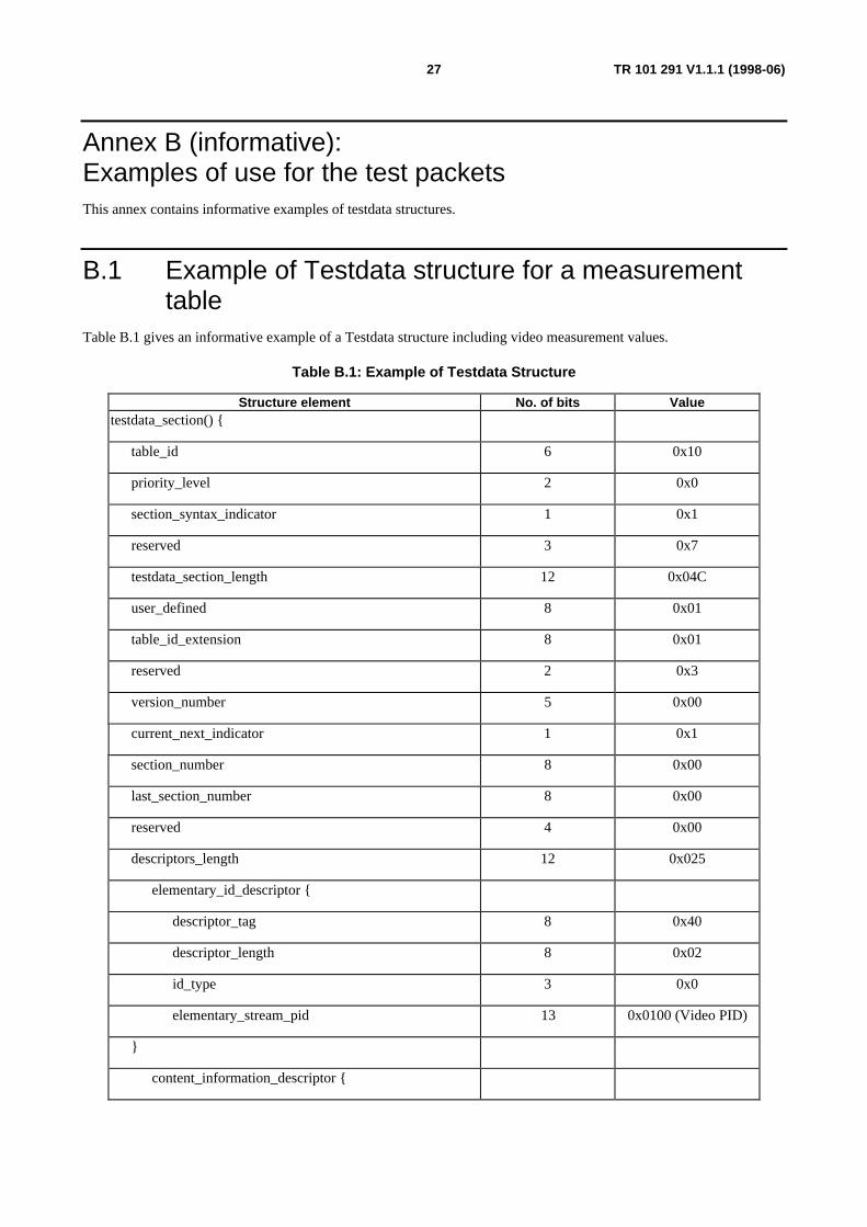
Annex B (informative):Examples of use for the test packetsThis annex contains informative examples of testdata structures.
B.1 Example of Testdata structure for a measurementtable
Table B.1 gives an informative example of a Testdata structure including video measurement values.
Table B.1: Example of Testdata Structure
Structure element No. of bits Valuetestdata_section() {
table_id 6 0x10
priority_level 2 0x0
section_syntax_indicator 1 0x1
reserved 3 0x7
testdata_section_length 12 0x04C
user_defined 8 0x01
table_id_extension 8 0x01
reserved 2 0x3
version_number 5 0x00
current_next_indicator 1 0x1
section_number 8 0x00
last_section_number 8 0x00
reserved 4 0x00
descriptors_length 12 0x025
elementary_id_descriptor {
descriptor_tag 8 0x40
descriptor_length 8 0x02
id_type 3 0x0
elementary_stream_pid 13 0x0100 (Video PID)
}
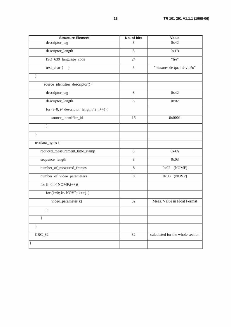
content_information_descriptor {
28 TR 101 291 V1.1.1 (1998-06)
Structure Element No. of bits Valuedescriptor_tag 8 0x42
descriptor_length 8 0x1B
ISO_639_language_code 24 "fre"
text_char { } 8 "mesures de qualité vidéo"
}
source_identifier_descriptor() {
descriptor_tag 8 0x42
descriptor_length 8 0x02
for (i=0; i< descriptor_length / 2; i++) {
source_identifier_id 16 0x0001
}
}
testdata_bytes {
reduced_measurement_time_stamp 8 0x4A
sequence_length 8 0x03
number_of_measured_frames 8 0x02 (NOMF)
number_of_video_parameters 8 0x03 (NOVP)
for (i=0;i< NOMF;i++){
for (k=0; k< NOVP; k++) {
video_parameter(k) 32 Meas. Value in Float Format
}
}
}
CRC_32 32 calculated for the whole section
}
29 TR 101 291 V1.1.1 (1998-06)
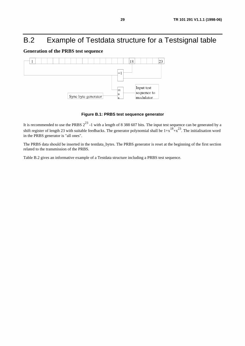
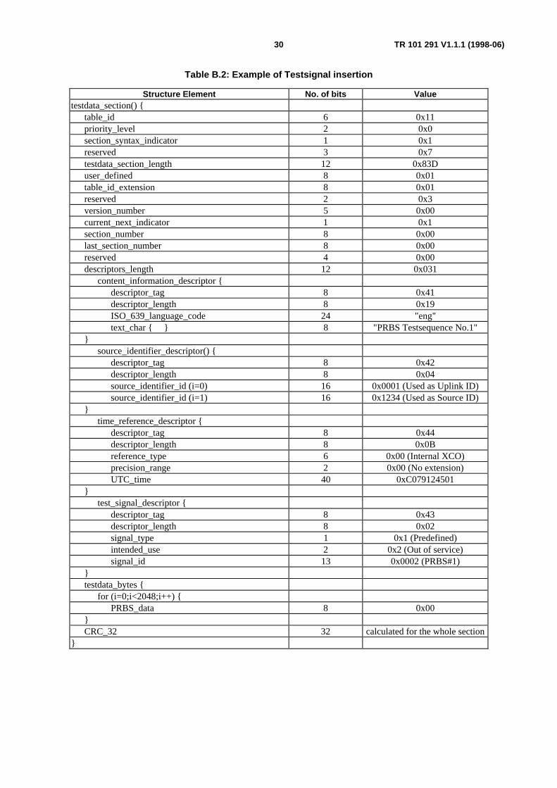
B.2 Example of Testdata structure for a Testsignal tableGeneration of the PRBS test sequence
Figure B.1: PRBS test sequence generator
It is recommended to use the PRBS 223 -1 with a length of 8 388 607 bits. The input test sequence can be generated by a
shift register of length 23 with suitable feedbacks. The generator polynomial shall be 1+x18+x23. The initialisation wordin the PRBS generator is "all ones".
The PRBS data should be inserted in the testdata_bytes. The PRBS generator is reset at the beginning of the first sectionrelated to the transmission of the PRBS.
Table B.2 gives an informative example of a Testdata structure including a PRBS test sequence.
30 TR 101 291 V1.1.1 (1998-06)
Table B.2: Example of Testsignal insertion
Structure Element No. of bits Valuetestdata_section() {
B.3 Example of Testdata structure for a Network StatusTable (NST)
Table B.3 gives an informative example of a Testdata structure, including a Network Status Table for transmission ofinformation (e.g. failure messages) about the availability of services as well as of service components such as video,audio and subtitling and of Service Information (SI) tables.
Table B.3: Example of Network Management Table
Structure Element No. of bits Valuetestdata_section() {
table_id 6 0x14
priority_level 2 0x0
section_syntax_indicator 1 0x0
reserved 3 0x7
testdata_section_length 12 0x00C
testdata_bytes {
transport_stream_id 16 0x0001
original_network_id 16 0x0002
NST_version_number 4 0x0
fault_source 12 0x03E9 (Multiplexer)
fault_type 16 0x0100 (Component of service missing)
fault_major 16 0x0300 (Service ID of missing service)
fault_minor 16 0x0002 (Audio component missing)
}
}
B.4 Example of Testdata structure for a Reception StatusTable (RST)
Table B.4 gives an informative example of a Test data structure including telemetry data tables generated by a satelliteon-board multiplexer. This type of multiplexer takes TSs as inputs and outputs a single TS or several TSs containingmultiple programmes. The input TSs come from different DVB-S demodulators.
Table B.4 gives information about the quality of the DVB-S signals received by the satellite, such as carrier level,frequency drift, lock status, decoding capacity overflow, etc. This information is formatted into blocks and passed intoan auxiliary input of the multiplexer. The multiplexer inserts the telemetry data into the output TS two times per second.
32 TR 101 291 V1.1.1 (1998-06)
Table B.4: Example of Multiplex Diagnostic Table
Structure element No. of bits Valuetestdata_section() {
table_id 6 0x13
priority_level 2 0x0
section_syntax_indicator 1 0x0
reserved 3 0x7
testdata_section_length 12 N × 8
testdata_bytes { N × 64 N blocks of 4 words of 16 bits
}
B.5 Example of test data structure for a Remote ControlTable (RCT)
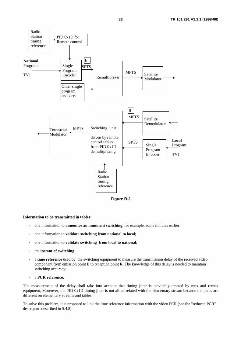
The need for remote control application is appearing in the terrestrial broadcasting environment.
It consists in controlling, from the emission site, the equipment in charge of switching from national programs to localprograms, or to advertising programs.
Figure B.2 illustrates an example of a transmission chain.
33 TR 101 291 V1.1.1 (1998-06)
Satellite Modulator
Single Program Encoder Remultiplexer
Satellite Demodulator
Switching unit
driven by remotecontrol tablesfrom PID 0x1Ddemultiplexing
Other singleprogramendoders
MPTS
MPTS
NationalProgram
TV1
SingleProgramEncoder
LocalProgram
TV1
SPTS
MPTSTerrestrialModulator
SPTS
PID 0x1D for Remote controlt bl
E
R
Radio Station timing reference
Radio Station timing reference
Figure B.2
Information to be transmitted in tables:
- one information to announce an imminent switching, for example, some minutes earlier;
- one information to validate switching from national to local;
- one information to validate switching from local to national;
- the instant of switching.
- a time reference used by the switching equipment to measure the transmission delay of the received videocomponent from emission point E to reception point R. The knowledge of this delay is needed to maintainswitching accuracy;
- a PCR reference.
The measurement of the delay shall take into account that timing jitter is inevitably created by mux and remuxequipment, Moreover, the PID 0x1D timing jitter is not all correlated with the elementary stream because the paths aredifferent on elementary streams and tables.
To solve this problem, it is proposed to link the time reference information with the video PCR (see the "reduced PCR"descriptor described in 5.4.8).
34 TR 101 291 V1.1.1 (1998-06)
The time_reference descriptor and the reduced PCR descriptor are sent together, for example, some minutes beforeswitching.
In this example, the switching equipment shall know the exact type of the elementary stream (audio, video, data -> seestream_type in PMT) for adjusting the switching criteria. Of course, the program number can be known by othersmeans, but direct indication is a more simple and rapid way. Moreover, this is a convenient link with other signalisation.
- Program number and the PID number of the PMT are conveyed in the program_descriptor (see 5.4.9).
- The "time reference descriptor" is used for coding the instant of switching. The precision shall be about themillisecond to be able to switch at a better accuracy than a picture duration (40 ms).
The type of the timing reference is a radio station.
Example:
On 93/10/13 at 12 h 45 mn 01 sec. 234 millisec.
Switching program number 5000 (0x1388) from national to local for the video (PID = 0x100) and the audio(PID=0x101) components. The PID of the PMT is 0x900.
table_id = 0x12 for remote_control_table
userdefined
8 lower bits are user defined: 0x01 = announcement of imminent switching
0x02 = switching to local
0x03 = switching to national
table_id_extension = 0x02 for switching_system
35 TR 101 291 V1.1.1 (1998-06)
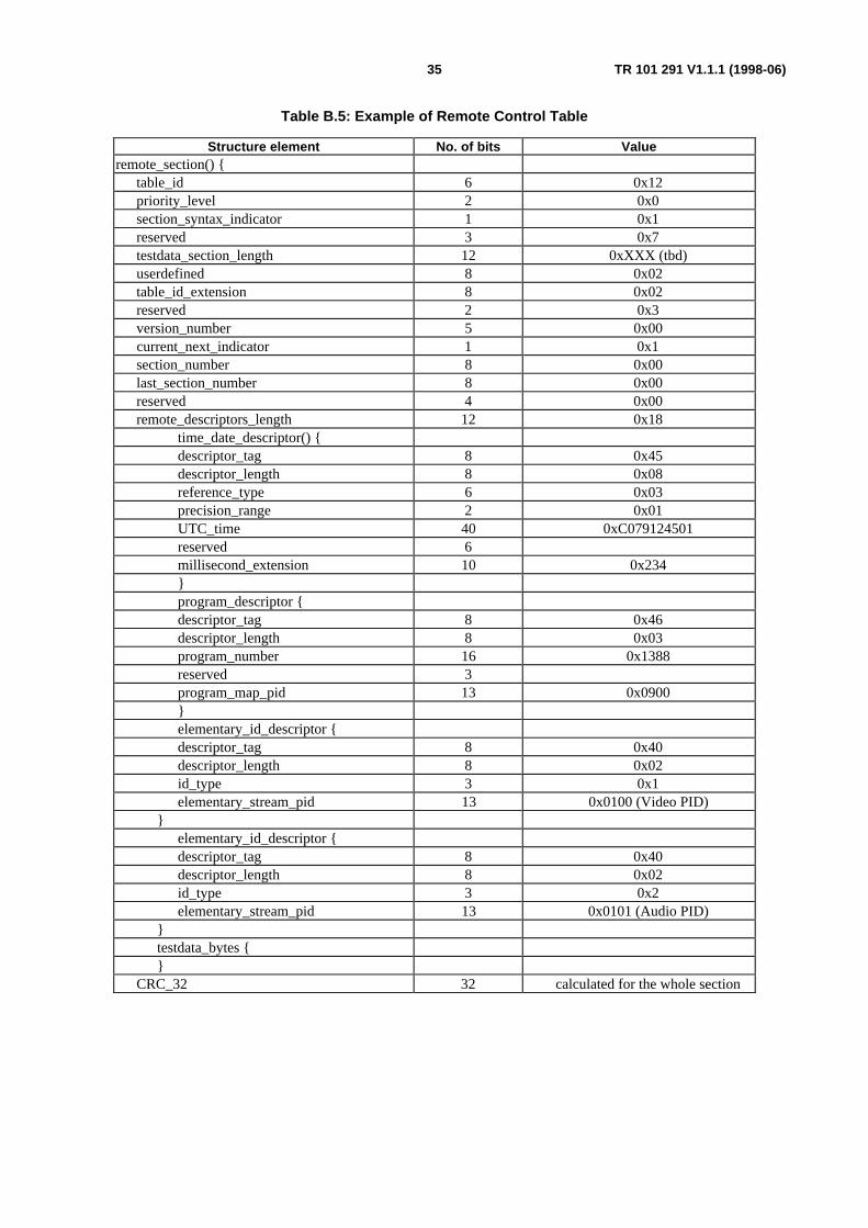
Table B.5: Example of Remote Control Table
Structure element No. of bits Valueremote_section() {
Annex C (informative):Examples for data ratesIn this annex C several examples are given for estimates of the data rate which needs to be reserved for certainapplications of the PID 0x1D.
Error messages signalling: Approx. 200 bit/s to 2 kbit/s.
This estimate is based on the assumption that the error messages are normally contained in one TS packet and that sucha packet is inserted periodically once every ten seconds up to once per second.
Test signals distribution (e.g. PRBS): 223-1: 8 Mbyte, over 30 seconds approx. 270 kbit/s.
Off-line measurements: Short time 100 % of transmission capacity.
Distribution of GPS information: Around 60 kbit/s.
Distribution of measurement values: 20 to 40 kbit/s for 1 video and 1 audio stream quality analysis, for other parametersdepending on repetition rate 1 to 10 kbit/s.
Control of remote equipment: Around 1 kbit/s.
Summary: For the above listed applications the range of 200 bit/s to > 270 kbit/s is sufficient while the upperlimit may only be required for comparably short periods of time.