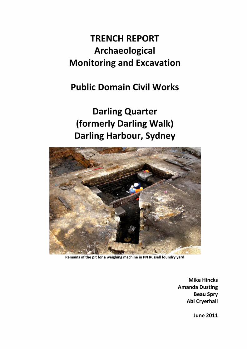
TRENCH REPORT Archaeological Monitoring and Excavation Public Domain Civil Works Darling Quarter (formerly Darling Walk) Darling Harbour, Sydney Remains of the pit for a weighing machine in PN Russell foundry yard Mike Hincks Amanda Dusting Beau Spry Abi Cryerhall June 2011
Transcript
TRENCH REPORT Archaeological
Monitoring and Excavation
Public Domain Civil Works
Darling Quarter (formerly Darling Walk) Darling Harbour, Sydney
Remains of the pit for a weighing machine in PN Russell foundry yard
Mike Hincks Amanda Dusting
Beau Spry Abi Cryerhall
June 2011
_________________________________________________________________________________Casey & Lowe Area 4 and 6, Public Domain Trench Report
Darling Quarter, Darling Harbour
EXECUTIVE SUMMARY Project The Darling (Walk) Quarter development was subject to an extensive archaeological investigation. The main phase of this work was undertaken between October 2008 and April 2009 and concentrated on the archaeological excavation of the basement footprint. Outside the basement extensive landscaping and other civil works within the public domain was also subject to a program of archaeological excavation. The archaeological areas impacted on by the public domain works were Area 4 – PN Russell Foundry, and Area 6 – Miller & Harrison’s Steam Sawmill. The archaeological work for the public domain began in February and ended in August 2010, and was conducted in phases linked to the civil works program. Report Methodologies This report combines four separate trench reports written by the trench supervisors for the public domain archaeological investigation:
Test Trench 35 – Area 4
Kiosk Excavation – Area 4
Balance Tanks Excavation – Area 4
Rain Water Tank Excavation – Area 6 Main Archaeological Findings Archaeological remains associated with the State significant PN Russell Foundry (Area 4) dating from the 1860s and with Miller & Harrison’s Steam Sawmill (Area 6) dating from the 1870s were recorded during the program. The main archaeological findings are as follows:
Kiosk PN Russell foundry footings Weighing machine pit structure Rail tracks for foundry wagons Yard surfaces
Balance Tanks Remains of Traver’s Wharf (1850s, pre-Russell foundry) 1850s/1860s reclamation evidence PN Russell rail tracks and wagon turntable
Rain Water Tank 1840s reclamation by Thomas Barker Brick structure from Dent’s timber yard (pre-1860s) Timber wharf c.1870s Engine and boiler base, Miller & Harrison Sawmill 1870s
_________________________________________________________________________________ Casey & Lowe Area 4 and 6, Public Domain Trench Report
Darling Quarter, Darling Harbour
CONTENTS
1.0 Introduction .................................................................................................................... 1 1.1 Background ............................................................................................................................ 1 1.2 Study Area ............................................................................................................................. 1 1.3 Archaeological Areas ............................................................................................................. 3 1.4 Archaeological Phases ........................................................................................................... 3 1.5 Limitations ............................................................................................................................. 3 1.6 Authorship ............................................................................................................................. 3 1.7 Common Abbreviations ......................................................................................................... 4
2.0 Public Domain Archaeological Investigation ..................................................................... 5 2.1 Overview ............................................................................................................................... 5 2.2 Site Prior to Excavation ......................................................................................................... 5 2.3 Public Domain Impacts .......................................................................................................... 5 2.4 Excavation Methodology ....................................................................................................... 6 2.5 Excavation Team ................................................................................................................... 6 2.6 Reporting Methodology ........................................................................................................ 6
3.0 Test Trench 35 – Area 4 ................................................................................................... 7 3.1 Introduction ........................................................................................................................... 7 3.2 Test Trench 35 ....................................................................................................................... 8
4.4.1 Reclamation and Levelling Fills .................................................................................... 14 4.5 Phase 6.1: 1840s to 1859 Development under Brodie & Craig ........................................... 15
5.0 Balance Tanks (BT1 and BT2) Excavation – Area 4 ............................................................39 5.1 Introduction ......................................................................................................................... 39
5.1.1 Study Area ................................................................................................................... 39 5.1.2 Archaeological Phases ................................................................................................. 40 5.1.3 Excavation Program ..................................................................................................... 40
5.2 Historical Background to Area 4 Balance Tanks .................................................................. 40 5.3 Excavation Results Overview ............................................................................................... 46 5.4 Phase 6.1: 1853 to 1856 Development – Travers’ Wharf ................................................... 47
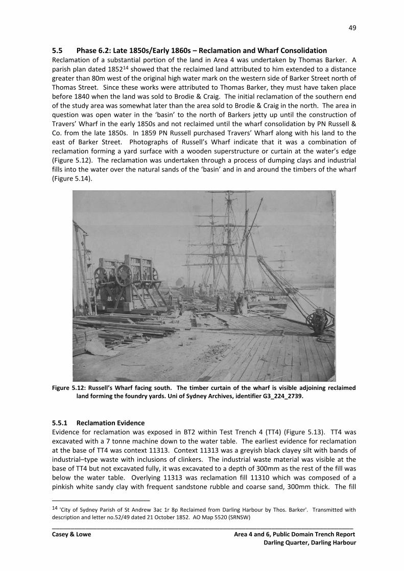
5.4.1 Timber Wharfage......................................................................................................... 47 5.5 Phase 6.2: Late 1850s/Early 1860s – Reclamation and Wharf Consolidation ..................... 49
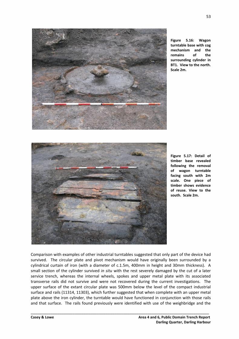
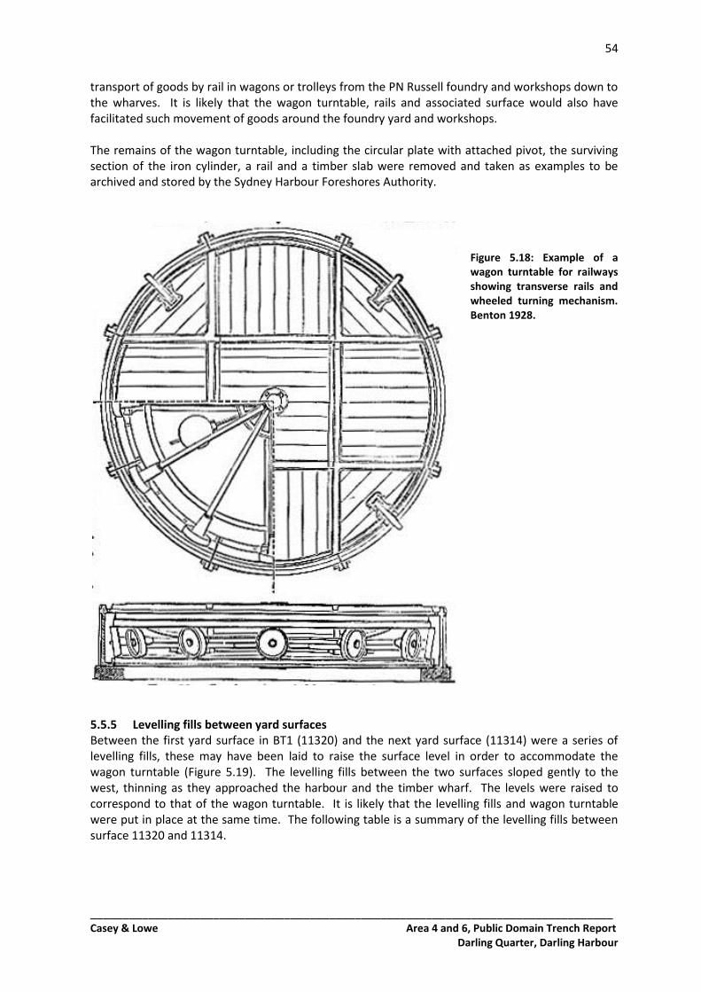
5.5.1 Reclamation Evidence ................................................................................................. 49 Wharf Consolidation.................................................................................................................... 51 5.5.2 First Yard Surfaces and Levelling Fill............................................................................ 51 5.5.3 Tramway - Railway ...................................................................................................... 52 5.5.4 Wagon turntable and timber base plate ..................................................................... 52 5.5.5 Levelling fills between yard surfaces ........................................................................... 54 5.5.6 Second Yard surface .................................................................................................... 56 5.5.7 Rails and timbers ......................................................................................................... 56 5.5.8 First phase of rails ....................................................................................................... 58 5.5.9 Second phase of rails- robbed-out track ..................................................................... 59 5.5.10 Third phase of rails and yard surface .......................................................................... 59 5.5.11 Levelling fill .................................................................................................................. 60
5.6 Phase 7.1: 1865-1875 PN Russell Foundry .......................................................................... 60 5.6.1 Forge Building .............................................................................................................. 60 5.6.2 Industrial Accumulation .............................................................................................. 62
5.7 Phase 7.2: 1875-1900 Abandonment and Demolition ........................................................ 63 5.7.1 Abandonment and Demolition .................................................................................... 63
5.8 Phases 8, 9, 10: Post-1900 Resumptions and Development ............................................... 63 5.8.1 Levelling Fills and Services ........................................................................................... 63
5.9 Summary of Results from the Balance Tanks Excavation ................................................... 64 6.0 Rain Water Tank Excavation – Area 6 ..............................................................................65
6.1 Introduction ......................................................................................................................... 65 6.1.1 Study Area ................................................................................................................... 65 6.1.2 Archaeological Phases ................................................................................................. 66 6.1.3 Excavation Program ..................................................................................................... 67
6.2 Historical Background for Area 6 Rain Water Tank Excavation .......................................... 67 6.3 Rain Water Tank Excavation Results Overview ................................................................... 73 6.4 Phase 5: Late 1830s/Early 1840s Reclamation .................................................................... 75
6.4.1 Machine Test Trench 1 ................................................................................................ 75 6.4.2 Machine Test Trench 2 ................................................................................................ 75 6.4.3 Machine Test Trench 3 ................................................................................................ 75 6.4.4 Machine Test Trench 4 ................................................................................................ 76
6.5 Phase 6.1: Post-Reclamation Development - 1840s ........................................................... 77 6.5.1 Levelling and Working Surfaces................................................................................... 77 6.5.2 Levelling Fills above reclamation on southern limit of excavation ............................. 79
6.6 Phase 6.2: 1850s-1860s Development ................................................................................ 80 6.6.1 Pre-1870s Building and Timber Surface ...................................................................... 80 6.6.2 Wharf Remains – 1850s? ............................................................................................. 83
6.7 Phase 7.1: 1860s-1870s Development ................................................................................ 85 6.7.1 Levelling Fills and Surfaces .......................................................................................... 85
_________________________________________________________________________________ Casey & Lowe Area 4 and 6, Public Domain Trench Report
6.8.1 Steam Engines and Sawmills ....................................................................................... 91 6.8.2 Archaeological Evidence from the Rain Water Tank Excavation ................................. 96 6.8.3 Engine base, retaining wall and fly-wheel housing ..................................................... 96 6.8.4 Boiler bases ................................................................................................................. 99 6.8.5 Construction Cut ........................................................................................................ 102 6.8.6 Buildings .................................................................................................................... 104 6.8.7 Associated surfaces and fills ...................................................................................... 106 6.8.8 Drain and sump ......................................................................................................... 108
6.9 Phases 8, 9, 10: Resumption and Twentieth-Century Development ................................ 109 6.9.1 Post-Steam Mill Levelling Fills ................................................................................... 109 6.9.2 Post-Resumption Fills and Services ........................................................................... 110 6.9.3 1980s Lakebed ........................................................................................................... 111
6.10 Summary of Results from the Rain Water Tank Excavation .............................................. 111 7.0 Summary of Results ...................................................................................................... 113
7.1 Archaeology of the Public Domain .................................................................................... 113 8.0 Bibliography ................................................................................................................. 115
1
_________________________________________________________________________________ Casey & Lowe Area 4 and 6, Public Domain Trench Report
Darling Quarter, Darling Harbour
1.0 Introduction
1.1 Background The Darling Walk development site was subject to extensive archaeological investigation, undertaken by Casey & Lowe Pty Ltd between 2008 and 2010. The archaeological assessment for the site identified potential for local and State significant archaeological remains and also outlined the development impacts. Based on this assessment an archaeological management strategy was developed. Recommendations included archaeological excavation within the basement footprint, while in areas of impact on the archaeological resource that were outside the basement, a program of testing and monitoring was recommended (with excavation if required). Casey & Lowe undertook the archaeological excavation within the basement footprint between October 2008 and April 2009. Areas outside the basement were also investigated as part of this program. To the northwest of the basement an area of dense piling was tested and found no archaeological remains (Section 3 this report). The footprint of the ‘Children’s Theatre’ was archaeologically excavated (See Trench Report: Area 8 CT, Vol 2, Section 7.5) as it contained remains of nineteenth-century Barker Street houses. Another phase of archaeological work was undertaken in 2010 in conjunction with the civil works for the public domain. The public domain area of Darling Walk was located to the west and northwest of the basement (Figure 1.1). This area contains the State significant remains of PN Russell foundry, dating to the 1860s. Development impacts in this area included excavation for a kiosk building, balance and rain water tanks (Figure 1.2). Overlays of the development on historic maps suggested that the areas of impacts were within the yard area of the foundry, therefore limiting the impact on the significant remains. Significant remains were to be retained in situ where redesign was possible. These areas were archaeologically investigated between February and July 2010. This report details the archaeological findings from:
Testing the pile-dense area (Area 4)
Kiosk footing excavation (Area 4)
Balance tanks excavation (Area 4)
Rain water tank excavation (Area 6)
1.2 Study Area The Darling Walk development site is located within the Darling Harbour precinct, on the western edge of Sydney Central Business District. It is located on the eastern side of the harbour and is bound by Harbour Street to the east, Bathurst Street to the north, Liverpool Street/Chinese Gardens to the south and Tumbalong Park to the west. The public domain is located to the west and northwest of the development site. It is located entirely on mid to late nineteenth-century reclaimed land.
2
_________________________________________________________________________________ Casey & Lowe Area 4 and 6, Public Domain Trench Report
Darling Quarter, Darling Harbour
Figure 1.1: The Darling walk site outlined in red with the public domain shaded green, on the 1865 plan of
the area. 1865 Trigonometric Survey of Sydney Section E2 Sheet 1, Historical Atlas of Sydney, City of Sydney Archives.
Figure 1.2: The public domain details overlaid on the 1865 plan of the site. The locations of deep
excavation are indicated (purple arrows). The kiosk footings are top, the balance tanks bottom left and the rain water tank bottom right. 1865 Trigonometric Survey of Sydney Section E2 Sheet 1, Historical Atlas of Sydney, City of Sydney Archives.
3
_________________________________________________________________________________ Casey & Lowe Area 4 and 6, Public Domain Trench Report
Darling Quarter, Darling Harbour
1.3 Archaeological Areas The site was divided into nine areas based on historical information and property boundaries (Figure 1.1). The following is a list of the main associations with each area in the nineteenth century:
• Area 1 = Wearne’s Wharf • Area 2 = William Orr Engineering • Area 3 = Anchor Flour Mill, Sawmill, Sugarworks • Area 4 = PN Russell Foundry • Area 5 = PN Russell Carriage Works and Boiler House • Area 6 = Miller & Harrison Timber Yards and Sawmill • Area 7 = Captain Brooks’ Slaughter House, Soap and Candle Factory • Area 8 = Workers’ Housing • Area 9 = Barker’s Mill
Parts of Areas 5 to 9 were within the basement footprint. Parts of Area 4, 6 and 7 were within the public domain (Figure 1.1). The pile-dense area testing, the kiosk and the balance tanks are within Area 4 and the rain water tank is within Area 6. Site plan locations, the site grid and excavated areas are represented on Plan 10.1 in Volume 4, Section 10 of the Excavation Report, while Plans 10.45 to 10.59 contain plans and sections relevant to this trench report.
1.4 Archaeological Phases The study area has been divided into 10 main archaeological phases that relate to all Areas:
Phase 1 Natural Landscape
Phase 2 Aboriginal Occupation
Phase 3 1788 to 1820s Early Foreshore Activity and Property Boundaries
Phase 4 1820s to late 1830s Barker’s Mill and Lands
Phase 5 Late 1830s/Early 1840s Reclamation
Phase 6 1840s to 1860s Residential, Industrial Development and Reclamation
Phase 7 1860s to 1900 Residential and Industrial Development
Phase 8 1900s to 1920 Resumption and Railways
Phase 9 1920s to 1980s Railways and Commercial Development
Phase 10 1980s Demolition and Re-Development Each area may have sub-phases specific to that area’s development. The archaeological evidence from the public domain mainly belongs to Phases 5, 6 and 7.
1.5 Limitations The archaeological work within the public domain was not limited in anyway.
1.6 Authorship This report has been written by Abi Cryerhall (Section 1, 2 and 7), Nick Harrop (Section 3), Mike Hincks (Section 4), Amanda Dusting (Sections 5 and 6) and Beau Spry (Section 6.8.1, contributions to Section 6 throughout). The main body of the report (Sections 3 to 6), containing the archaeological descriptions and phasing written by Harrop, Hincks, Dusting and Spry has been reviewed and amended by Cryerhall. This report has been reviewed and edited by Mike Hincks.
4
_________________________________________________________________________________ Casey & Lowe Area 4 and 6, Public Domain Trench Report
Darling Quarter, Darling Harbour
1.7 Common Abbreviations AHD Australian Height Datum MTT Machine Test Trench NLA National Library of Australia RL Reduced level (in metres according to Australian Height Datum) SLNSW State Library of NSW SRNSW State Records of NSW TT Test Trench
5
_________________________________________________________________________________ Casey & Lowe Area 4 and 6, Public Domain Trench Report
Darling Quarter, Darling Harbour
2.0 Public Domain Archaeological Investigation
2.1 Overview The program of archaeological investigations within the public domain of the Darling Walk development site began in February 2010 and was completed by August 2010. The Kiosk excavation was undertaken in February and March; the Balance Tanks were excavated in June and July; the Rain Water Tank in July and August. Previous testing outside the basement footprint was undertaken in January 2009.
2.2 Site Prior to Excavation The public domain area is located in the former ‘lake bed’ associated with SegaWorld. The base of the concrete-lined lake was located at RL 2.1m, about 2m below the ground level of the Darling Harbour pavement and play ground to the west. The archaeological remains in the Darling Walk site start at around RL 1.8m.
2.3 Public Domain Impacts For the most part, landscaping for the public domain consisted of filling-in and raising the ground level of the former lake bed. Other civil works with minor impacts included drainage channels, services, playground equipment footings and tree plantings. However several areas within the public domain were subject to deeper excavation below RL 1.8m. These were the footings for a Kiosk building, deep excavations for the installation of balance tanks for a water feature, and a deep excavation for a rain water collection tank (Figure 2.1). Figure 2.1: The location of the Kiosk, Balance Tanks and Rain Water Tank excavation areas on the 1880
plan. H Percy Dove, Plans of Sydney, block 91, 1880, Historical Atlas of Sydney, City of Sydney Archives.
Kiosk
Balance Tanks
Rain Water Tank
6
_________________________________________________________________________________ Casey & Lowe Area 4 and 6, Public Domain Trench Report
Darling Quarter, Darling Harbour
2.4 Excavation Methodology The three areas of identified impacts (Kiosk, Balance Tanks and Rain Water Tank) were excavated archaeologically in advance of the construction work. The archaeological work was undertaken in conjunction with the civil works for the public domain. The excavation footprints were marked out by a surveyor. The concrete lake-bed, in the case of the Kiosk and Rain Water Tank, was removed by a 20 tonne excavator. A combination of a 7 tonne and 12 tonne machine was used to remove the modern fills to the top of archaeological surfaces, structures and fills. This was done under archaeological supervision. The trenches were cleaned-up by hand, archaeological features were excavated, recorded (context sheet and photography) and planned to scale by the team of archaeologists. Mechanical assistance was used where necessary. The trenches and main structural remains were surveyed and located within the development and archaeological grid. This excavation methodology was established for the main excavation program and is outlined in the Archaeological Management Strategy.1 Archaeological monitoring was also undertaken throughout the public domain works. As most of the impacts were within Area 4, the site of the State significant PN Russell foundry, significant remains were to be retained in situ if redesign was possible. Within the Kiosk excavation, the footings of the foundry building were exposed. Redesign was possible and the footings were retained in situ.
2.5 Excavation Team The archaeological work for the Public Domain of the Darling Walk development was undertaken by Casey & Lowe Pty Ltd. The Excavation Director for the project was Dr Mary Casey; the Site Director was Abi Cryerhall; Supervisors were Mike Hincks and Amanda Dusting; Archaeologists were Beau Spry, Nick Harrop, Sandra Kuiters and Dr Bernadette McCall.
2.6 Reporting Methodology This report provides the background to the archaeological work in the public domain of the Darling Walk site. Sections 3 to 6 provide the detailed stratigraphic descriptions of the archaeological remains uncovered during the project. These have been written by the supervising archaeologist for each trench. This report also contains the results of testing undertaken during the main phase of archaeological work associated with the basement (See Trench Reports for Areas 5 to 9). This area is located northwest of the basement and was to be densely piled. This area is not within the public domain, but below the northern end of the new building. Also outside the basement was the Children’s Theatre, and this is subject to a separate report (Area 8 CT Trench Report).
1 Casey & Lowe 2008b.
7
_________________________________________________________________________________ Casey & Lowe Area 4 and 6, Public Domain Trench Report
Darling Quarter, Darling Harbour
3.0 Test Trench 35 – Area 4
3.1 Introduction Archaeological testing within Area 4 of the Darling Walk development was undertaken from 28-30 January 2009. The test area was outside the main basement footprint, to the northwest and located within an area of dense piling associated with the new building (Figure 3.1). A single test trench was excavated in the general location of 1840s brick terrace houses and backyards associated with the PN Russell foundry. The purpose of the testing was to ascertain the degree of survival of archaeological remains in this area. The trench was located between 2 of the 3 proposed new piles associated with the current development. Figure 3.1: The location of TT35 is indicated by the arrow. The outline of the new buildings is in blue, and
the basement has been overlaid within this (black detail). 1865 Trigonometric Survey of Sydney Section E2 Sheet 1, Historical Atlas of Sydney, City of Sydney Archives.
The trench was excavated mechanically using a 20 tonne excavator, using both a tooth and straight edged bucket where appropriate. Post-1980 fills were removed in bulk, after which the trench was reduced in 200 mm spits. The trench was benched after the removal of each metre of fill to allow safe access for archaeological recording. A test pit was manually excavated at the level of reclamation to confirm this interpretation of the fill. Testing was supervised by Nick Harrop with the assistance of Rhian Jones (Archaeologists, Casey & Lowe), under the direction of Abi Cryerhall (Archaeologist, Casey and Lowe).
8
_________________________________________________________________________________ Casey & Lowe Area 4 and 6, Public Domain Trench Report
Darling Quarter, Darling Harbour
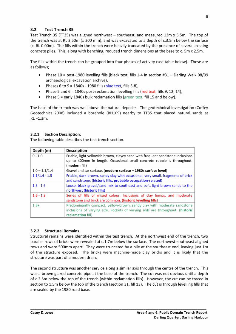
3.2 Test Trench 35 Test Trench 35 (TT35) was aligned northwest – southeast, and measured 13m x 5.5m. The top of the trench was at RL 3.50m (± 200 mm), and was excavated to a depth of c.3.5m below the surface (c. RL 0.00m). The fills within the trench were heavily truncated by the presence of several existing concrete piles. This, along with benching, reduced trench dimensions at the base to c. 5m x 2.5m. The fills within the trench can be grouped into four phases of activity (see table below). These are as follows;
Phase 10 = post-1980 levelling fills (black text, fills 1-4 in section #31 – Darling Walk 08/09 archaeological excavation archive),
Phase 5 = early 1840s bulk reclamation fills (green text, fill 15 and below). The base of the trench was well above the natural deposits. The geotechnical investigation (Coffey Geotechnics 2008) included a borehole (BH109) nearby to TT35 that placed natural sands at RL −1.3m. 3.2.1 Section Description: The following table describes the test trench section.
up to 400mm in length. Occasional small concrete rubble is throughout. (modern fill)
1.0 – 1.1/1.4 Gravel and tar surface. (modern surface – 1980s surface level)
1.1/1.4 - 1.5
Friable, dark brown, sandy clay with occasional, very small, fragments of brick and sandstone. (historic fills, probable occupation-related)
1.5 - 1.6 Loose, black gravel/sand mix to southeast and soft, light brown sands to the northwest (historic fills)
1.6 - 1.8 Series of fills of mixed colour. Inclusions of clay lumps, and moderate sandstone and brick are common. (historic levelling fills)
1.8+ Predominantly compact, yellow-brown, sandy clay with moderate sandstone inclusions of varying size. Pockets of varying soils are throughout. (historic reclamation fill)
3.2.2 Structural Remains Structural remains were identified within the test trench. At the northwest end of the trench, two parallel rows of bricks were revealed at c.1.7m below the surface. The northwest-southeast aligned rows and were 500mm apart. They were truncated by a pile at the southeast end, leaving just 1m of the structure exposed. The bricks were machine-made clay bricks and it is likely that the structure was part of a modern drain. The second structure was another service along a similar axis through the centre of the trench. This was a brown glazed concrete pipe at the base of the trench. The cut was not obvious until a depth of c.2.5m below the top of the trench (within reclamation fills). However, the cut can be traced in section to 1.5m below the top of the trench (section 31, fill 13). The cut is through levelling fills that are sealed by the 1980 road base.
9
_________________________________________________________________________________ Casey & Lowe Area 4 and 6, Public Domain Trench Report
Darling Quarter, Darling Harbour
Location of TT35 to NW SW facing section
Test pit location facing NW Limit of excavation facing NW
3.2.3 Test Trench RL Summary
Phase Description RL Top - Base
10 Modern Fill/ Surface RL 3.5 m - RL 2.5 - 2.2 m
6 to 9 Earlier Fills (possibly historic) RL 2.5 m - RL 2.1 m
5 to 6 Post-Reclamation Levelling Fills RL 2.1 m - RL 1.8 m
5 Reclamation Fill RL 1.8 m - ?
3.3 Conclusions The test trench revealed that there are quite a number of unidentified modern disturbances in the area, such as modern drains and large concrete piles. These were located throughout but apparently concentrated in the southern portion of the trench. While difficult to interpret, the historic fills and probable yard deposits (1840s to 1900s+) do demonstrate some stratigraphic integrity in the northern half of the trench and therefore there appears to be some degree of archaeological survival to the north and northeast. However, the two proposed piles do not impact significantly on archaeological remains associated with the PN Russell foundry as they are located in previously impacted areas and within pre-foundry (c.1840s) reclamation fills, as demonstrated by this test trench (TT 35).
10
_________________________________________________________________________________ Casey & Lowe Area 4 and 6, Public Domain Trench Report
Darling Quarter, Darling Harbour
4.0 Kiosk Excavation – Area 4
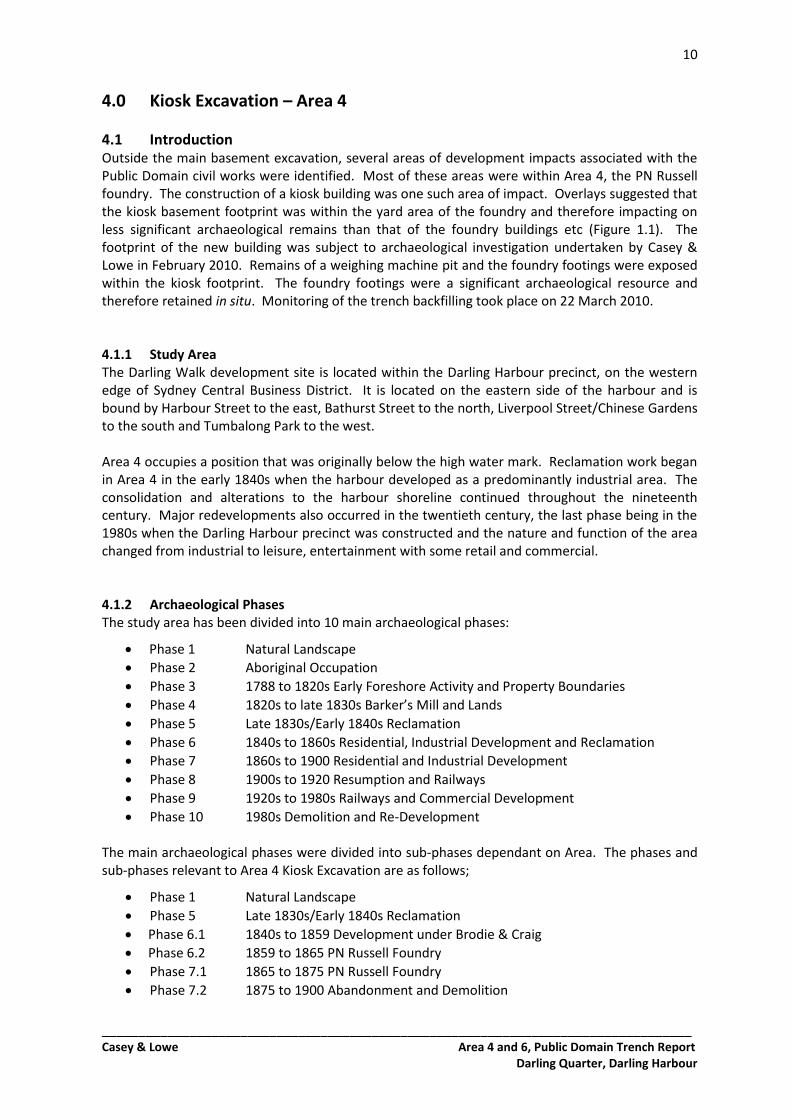
4.1 Introduction Outside the main basement excavation, several areas of development impacts associated with the Public Domain civil works were identified. Most of these areas were within Area 4, the PN Russell foundry. The construction of a kiosk building was one such area of impact. Overlays suggested that the kiosk basement footprint was within the yard area of the foundry and therefore impacting on less significant archaeological remains than that of the foundry buildings etc (Figure 1.1). The footprint of the new building was subject to archaeological investigation undertaken by Casey & Lowe in February 2010. Remains of a weighing machine pit and the foundry footings were exposed within the kiosk footprint. The foundry footings were a significant archaeological resource and therefore retained in situ. Monitoring of the trench backfilling took place on 22 March 2010. 4.1.1 Study Area The Darling Walk development site is located within the Darling Harbour precinct, on the western edge of Sydney Central Business District. It is located on the eastern side of the harbour and is bound by Harbour Street to the east, Bathurst Street to the north, Liverpool Street/Chinese Gardens to the south and Tumbalong Park to the west. Area 4 occupies a position that was originally below the high water mark. Reclamation work began in Area 4 in the early 1840s when the harbour developed as a predominantly industrial area. The consolidation and alterations to the harbour shoreline continued throughout the nineteenth century. Major redevelopments also occurred in the twentieth century, the last phase being in the 1980s when the Darling Harbour precinct was constructed and the nature and function of the area changed from industrial to leisure, entertainment with some retail and commercial. 4.1.2 Archaeological Phases The study area has been divided into 10 main archaeological phases:
Phase 1 Natural Landscape
Phase 2 Aboriginal Occupation
Phase 3 1788 to 1820s Early Foreshore Activity and Property Boundaries
Phase 4 1820s to late 1830s Barker’s Mill and Lands
Phase 5 Late 1830s/Early 1840s Reclamation
Phase 6 1840s to 1860s Residential, Industrial Development and Reclamation
Phase 7 1860s to 1900 Residential and Industrial Development
Phase 8 1900s to 1920 Resumption and Railways
Phase 9 1920s to 1980s Railways and Commercial Development
Phase 10 1980s Demolition and Re-Development The main archaeological phases were divided into sub-phases dependant on Area. The phases and sub-phases relevant to Area 4 Kiosk Excavation are as follows;
Phase 1 Natural Landscape
Phase 5 Late 1830s/Early 1840s Reclamation
Phase 6.1 1840s to 1859 Development under Brodie & Craig
Phase 6.2 1859 to 1865 PN Russell Foundry
Phase 7.1 1865 to 1875 PN Russell Foundry
Phase 7.2 1875 to 1900 Abandonment and Demolition
11
_________________________________________________________________________________ Casey & Lowe Area 4 and 6, Public Domain Trench Report
Darling Quarter, Darling Harbour
4.1.3 Excavation Program A program of excavation was undertaken between 15 and 26 February, 2010. Excavation was confined to the area to be impacted upon by the kiosk and plant room which corresponded to a section of the yard area of the PN Russell foundry. The trench was roughly rectangular in plan and measured 18m north-south by 15m. Excavation started from the base of the former lake-bed at RL 2.1m. The maximum depth of the Kiosk excavation was at RL 0.7m within a small test trench. Excavation was initiated with a 20 tonne excavator to remove the late twentieth-century concrete surface and the upper fills of the site. Further excavation was by hand. The site was planned and recorded with reference to a site grid that was used in all areas of the wider Darling Walk project. The backfilling of the trench was monitored on 22 March to ensure the remains to be retained in situ were not damaged in the process. The excavation director was Dr Mary Casey and the site director was Abi Cryerhall. The site was planned by Amanda Dusting and supervised by Mike Hincks. Assistants were Beau Spry and Nicholas Harrop. Machine excavation was by Theos Bros.
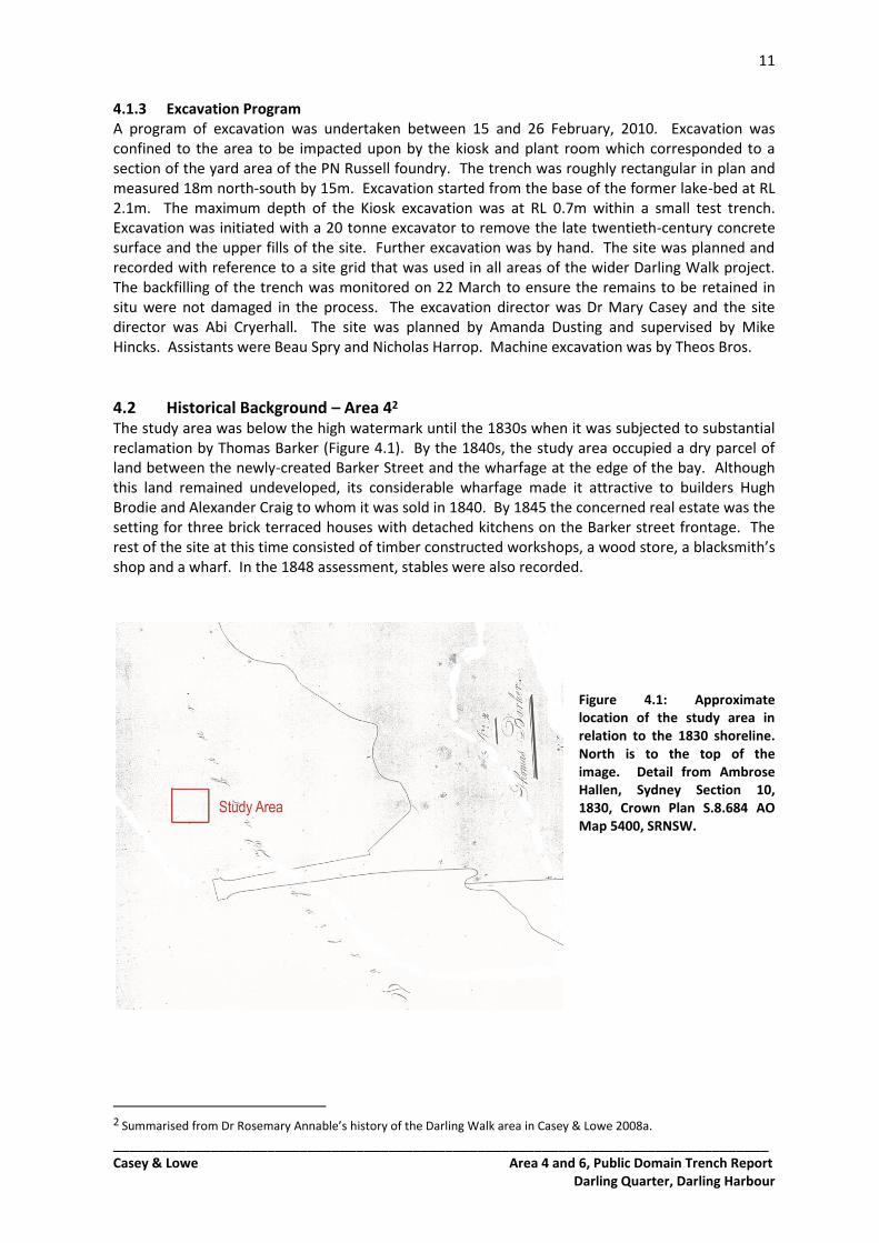
4.2 Historical Background – Area 42 The study area was below the high watermark until the 1830s when it was subjected to substantial reclamation by Thomas Barker (Figure 4.1). By the 1840s, the study area occupied a dry parcel of land between the newly-created Barker Street and the wharfage at the edge of the bay. Although this land remained undeveloped, its considerable wharfage made it attractive to builders Hugh Brodie and Alexander Craig to whom it was sold in 1840. By 1845 the concerned real estate was the setting for three brick terraced houses with detached kitchens on the Barker street frontage. The rest of the site at this time consisted of timber constructed workshops, a wood store, a blacksmith’s shop and a wharf. In the 1848 assessment, stables were also recorded.
Figure 4.1: Approximate location of the study area in relation to the 1830 shoreline. North is to the top of the image. Detail from Ambrose Hallen, Sydney Section 10, 1830, Crown Plan S.8.684 AO Map 5400, SRNSW.
2 Summarised from Dr Rosemary Annable’s history of the Darling Walk area in Casey & Lowe 2008a.
12
_________________________________________________________________________________ Casey & Lowe Area 4 and 6, Public Domain Trench Report
Darling Quarter, Darling Harbour
The 1855 survey showed the excavation area as an empty yard to the south of several large sheds and the Barker Street houses (Figure 4.2). In 1859 PN Russell Engineering acquired the land and proceeded to develop their major foundry works on the site. By 1864, extensive building had taken place on the site, with a moulding shed and workshop constructed onto the back of the houses that were then used as offices. A large smith's shop was constructed on the previously empty yard area on the Barker Street frontage. Smaller stores and workshops littered the yard area along with cranes and tracks for wagons.
Figure 4.2: Detail from the 1855 Trigonometric Survey of Sydney showing the approximate location of the excavated area (unbroken red line) and the Darling Walk site boundary (broken red line). North is to the top of the image. 1855 Trigonometric Survey of Sydney CRS 502/19, Sheet 19. Historical Atlas of Sydney, City of Sydney Archives.
Figure 4.3: Approximate location of the excavated area (unbroken red line) in relation to the foundry buildings. The greater Darling Walk site boundary appears as a broken red line. North is to the top of the image. Detail from H. Percy Dove Plan, block 91, 1880.
Although the foundry closed in 1875, the large workshops were still shown on the 1880 Percy Dove plan (Figure 4.3). The site appears to have been used for access to its wharf and stores during this period. In 1900 the site was purchased by the Adelaide Steamship Co., and shortly after, the land was annexed by the NSW Government as part of the Darling Harbour Resumptions.
13
_________________________________________________________________________________ Casey & Lowe Area 4 and 6, Public Domain Trench Report
Darling Quarter, Darling Harbour
The foundry buildings were demolished and the wharf rebuilt as part of the cleansing process after the outbreak of plague. Because the site had seen little in the way of upkeep since the closure in 1875, it may have been seen as a significant harbourer of unhealthy elements. In 1910 the northern half of the site was largely vacant with the exception of a stable in the north-east corner. The southern half was being utilised by the fuel merchants Warburton & Son. By 1920 the site was levelled, infilled, and became an extension of the Darling Harbour Goods Yards.
4.3 Phase 1 – Natural Landscape The landscape prior to reclamation was formed during the late stages of the Holocene marine transgression. This period witnessed the sea invasion of the Parramatta river valley mouth, creating the ria of Port Jackson. Marine sediments accumulated at the fringes of the dendritically shaped harbour, creating tidal mudflats at the southern edge of Cockle Bay and other locations in the drowned valley mouth. The underlying geology of Hawkesbury sandstone and the remnants of the Wianamatta shales framed the mudflats of the study area in a steeply undulating landscape that was likely vegetated by coastal sandstone gully forest including Angophora costata, Eucalyptus punctata and Eucalyptus tereticornis. Saltmarsh communities of sedges and halophytic succulent shrubs such as Sporobolus virginicus and Sarcocornia quinqueflora likely fringed the bay at its southern periphery. Area 4 was largely below the high water mark prior to reclamation efforts in the early 1840s. The natural environment of the Kiosk excavation area had little potential for pre-1840s archaeological remains. The excavated area represented a position some distance west of the mudflats associated with the original shoreline, and was well within the deeper waters of the harbour.
4.4 Phase 5 – Late 1830s/Early 1840s Reclamation Reclamation of a substantial portion of the land in the study area was undertaken by Thomas Barker. A parish plan dated 18523 showed that the reclaimed land attributed to him extended to a distance greater than 80m west of the original high water mark on the western side of Barker Street north of Thomas Street. Since these works were attributed to Thomas Barker, they must have taken place before 1840 when the land was sold to Brodie & Craig. The western extent of the reclaimed land was to remain fixed in this position until 1900. Evidence of reclamation was exposed in Test Trench 2 (TT2) where several levelling fills and bulk reclamation fill were exposed to a depth of RL 0.65m (Figure 4.4; Section #55 Plan 10.47, Vol 4 Section 10). TT2 was a rectangular trench that extended 5.20m south from the foundry wall at a width of 2.10m.
3 'City of Sydney Parish of St Andrew 3ac 1r 8p Reclaimed from Darling Harbour by Thos. Barker'. Transmitted with description and letter no.52/49 dated 21 October 1852. AO Map 5520 (SRNSW).
14
_________________________________________________________________________________ Casey & Lowe Area 4 and 6, Public Domain Trench Report
Darling Quarter, Darling Harbour
Figure 4.4: West-facing section of TT2 showing the levelling fills beneath the exposed yard surface (11138)
associated with Brodie & Craig (top of image). An early service trench can be seen at the right. View to the east. Scale 1m.
4.4.1 Reclamation and Levelling Fills At RL 0.65m, a thin and loosely horizontal band of coarse, black industrial waste (11147) was the earliest fill to be exposed in the test trench. It was composed of 3-5mm gravels, a fine grained and skin-staining soot-like material, and a coarse-grained sandy component. Occasional patches of unconsolidated iron oxide particles appeared in the mix. The largely horizontal surface that was produced suggested that this may have been a levelling fill or one-time exposed area during the reclamation process. In the southern part of the trench, with a tip line suggesting it was dumped from the south, a small quantity of coarse-grained crushed sandstone and fine clay particles (11146) was present to a depth of 150mm above 11147. A service trench (11109) had cut the fill, denying any further knowledge of its southern extent. Pockets of red and yellow clays were poorly mixed throughout the fill. A large quantity of tightly compacted, coarse-grained crushed sandstone and fine clay particles (11144) covered 11147 and 11146 to a depth of 240mm and produced a flat surface at its upper limit. It was predominantly yellow-brown with small pockets of white clay and occasional red sandstone fragments of up to 20mm GL. A gently sloping tip line (although these can be deceptive in section) suggested that the fill could not have been dumped from the north. In the cavity created by the tip line of 11144 and the gentle upward slope of 11147 was a sticky and coarse mix of tightly compacted crushed pink and white sandstone with a substantial but fine clay component (11143). It was its deepest in the cavity at 320mm, and capped the fill 11144 to a depth of 40mm in most of the trench. Capping the bulk of 11143 to a depth of 300mm, with a moderately sloping tip line to the south was a combination of coarsely crushed pink sandstone and larger fragments (11142). It was tightly compacted and only appeared in the north of the trench. At the base of the tip line, and capping 11143 where it was not covered by 11142, was a thin layer of dark grey fine clay particles and sands (11145) that may have represented an accumulation on the
15
_________________________________________________________________________________ Casey & Lowe Area 4 and 6, Public Domain Trench Report
Darling Quarter, Darling Harbour
surface of exposed reclamation fills. The black skin-staining properties if this mix suggested a soot or ash component. Covering 11145 and producing a flat surface consistent with the upper limit of 11142, was a 190mm-deep fill of yellow-brown coarse-grained sands with a significant component of yellow fine clay particles (11141). Included in the mix were large pieces of broken sandstone and smaller, semi crushed fragments.
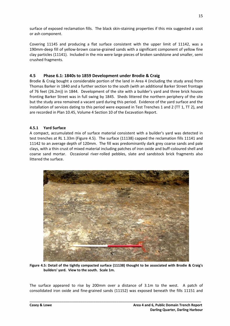
4.5 Phase 6.1: 1840s to 1859 Development under Brodie & Craig Brodie & Craig bought a considerable portion of the land in Area 4 (including the study area) from Thomas Barker in 1840 and a further section to the south (with an additional Barker Street frontage of 76 feet (26.2m)) in 1844. Development of the site with a builder’s yard and three brick houses fronting Barker Street was in full swing by 1845. Sheds littered the northern periphery of the site but the study area remained a vacant yard during this period. Evidence of the yard surface and the installation of services dating to this period were exposed in Test Trenches 1 and 2 (TT 1, TT 2), and are recorded in Plan 10.45, Volume 4 Section 10 of the Excavation Report. 4.5.1 Yard Surface A compact, accumulated mix of surface material consistent with a builder's yard was detected in test trenches at RL 1.33m (Figure 4.5). The surface (11138) capped the reclamation fills 11141 and 11142 to an average depth of 120mm. The fill was predominantly dark grey coarse sands and pale clays, with a thin crust of mixed material including patches of iron oxide and buff-coloured shell and coarse sand mortar. Occasional river-rolled pebbles, slate and sandstock brick fragments also littered the surface. Figure 4.5: Detail of the tightly compacted surface (11138) thought to be associated with Brodie & Craig's
builders' yard. View to the south. Scale 1m.
The surface appeared to rise by 200mm over a distance of 3.1m to the west. A patch of consolidated iron oxide and fine-grained sands (11152) was exposed beneath the fills 11151 and
16
_________________________________________________________________________________ Casey & Lowe Area 4 and 6, Public Domain Trench Report
Darling Quarter, Darling Harbour
11153 in an area of 400mm x 900mm. In compaction and composition it appeared identical to iron oxide stained parts of 11138. The uneven nature of the surface may have necessitated the introduction of further levelling fills before the construction of the foundry in Phase 6.2 (see below). 4.5.2 Services The surface was cut by a service trench that accommodated a salt glazed earthenware pipe of 200mm diameter (Figure 4.6). The cut was 480mm wide with tapered sides and a concave base at a depth of 650mm. The pipe contained a build-up of dark grey to black silty material. It contained fine sands and had suggestions of an organic component. The pipe was packed with a mixture of pink plastic clays and coarse brown sands. The service was oriented east-west and may have been associated with the residential development on the eastern side of Barker Street, as pipes there appeared to run west to the harbour.
Figure 4.6: The service trench exposed in TT2 (immediately left of the 1m scale). View to the east.
4.6 Phase 6.2: 1859-1865 PN Russell Foundry PN Russell further developed the site in the years after 1859 when they took over Brodie & Craig's yard and set up an engine works. The site would remain characterised by the foundry buildings until 1900 when the site was cleared and the structural fabric demolished. By 1864, the houses fronting Barker Street had been incorporated into the foundry and were being used as offices. There were two large workshops on the site and at least two smaller storehouses. By 1864 the study area had been impacted on by construction of the foundry and at least one set of tracks to facilitate the movement of wagons in and out of the workshops. Stratigraphic evidence suggested that a second set of tracks and a weighbridge 6.2m south of the foundry wall are also likely to have been constructed in this phase, although they were not shown on plan until 1869. This sub-phase of activity was recorded in Plan 10.45, Volume 4 Section 10 of the Excavation Report. 4.6.1 Levelling Fills and Pre-Construction Surface The pre-construction surface was produced by levelling the upper limits of four fills in the study area. The fills were imported above the Brodie & Craig yard surface, raising it by up to 300mm. The fills appeared to be introduced to the site from the north.
17
_________________________________________________________________________________ Casey & Lowe Area 4 and 6, Public Domain Trench Report
Darling Quarter, Darling Harbour
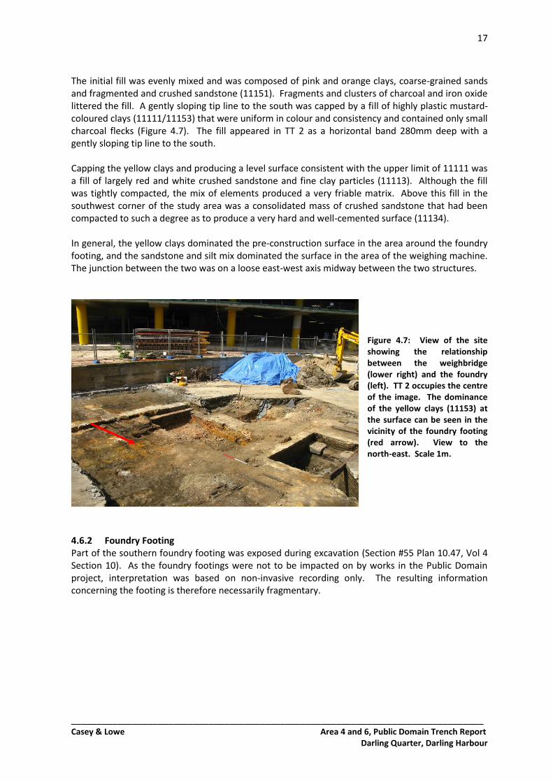
The initial fill was evenly mixed and was composed of pink and orange clays, coarse-grained sands and fragmented and crushed sandstone (11151). Fragments and clusters of charcoal and iron oxide littered the fill. A gently sloping tip line to the south was capped by a fill of highly plastic mustard-coloured clays (11111/11153) that were uniform in colour and consistency and contained only small charcoal flecks (Figure 4.7). The fill appeared in TT 2 as a horizontal band 280mm deep with a gently sloping tip line to the south. Capping the yellow clays and producing a level surface consistent with the upper limit of 11111 was a fill of largely red and white crushed sandstone and fine clay particles (11113). Although the fill was tightly compacted, the mix of elements produced a very friable matrix. Above this fill in the southwest corner of the study area was a consolidated mass of crushed sandstone that had been compacted to such a degree as to produce a very hard and well-cemented surface (11134). In general, the yellow clays dominated the pre-construction surface in the area around the foundry footing, and the sandstone and silt mix dominated the surface in the area of the weighing machine. The junction between the two was on a loose east-west axis midway between the two structures.
Figure 4.7: View of the site showing the relationship between the weighbridge (lower right) and the foundry (left). TT 2 occupies the centre of the image. The dominance of the yellow clays (11153) at the surface can be seen in the vicinity of the foundry footing (red arrow). View to the north-east. Scale 1m.
4.6.2 Foundry Footing Part of the southern foundry footing was exposed during excavation (Section #55 Plan 10.47, Vol 4 Section 10). As the foundry footings were not to be impacted on by works in the Public Domain project, interpretation was based on non-invasive recording only. The resulting information concerning the footing is therefore necessarily fragmentary.
18
_________________________________________________________________________________ Casey & Lowe Area 4 and 6, Public Domain Trench Report
Darling Quarter, Darling Harbour
Figure 4.8: Foundation stones of the foundry (11149) exposed at the south-facing section of TT2. View to the north. Scale 1m.
The cut that accommodated the footing was detected in TT 2 only, on the exterior side of the foundation. The cut was vertical on the southern side and the rectangular foundation blocks were built up against it. The cut (11148) was 440mm deep with a sharp break of slope to a seemingly flat base. A small amount of packing fill (up to 40mm) had been introduced to the base of the cut to produce a level surface on which the footing could be laid. This material was also used to pack the footing within the cut. It was a mixed fill of yellow-red clays and coarse-grained sands (70% sand), crushed sandstone and charcoal (11150). The mixed deposit was pale pink-brown in colour. In the area of TT 2, the cut was initiated in the surface 11151. The footing (11149) was constructed with large rectangular and neatly cut sandstone blocks (Figure 4.8). The foundation was stepped so that the top course was 340mm narrower than the lower course on the southern side. Blocks in the top course were of varying length. They were laid head-to-head in a single row. Excepting those at intersections with dividing walls, the blocks in the top course were uniformly 700mm wide and 280mm deep. The greatest block in the top course was 1.14m long. At intersections with dividing walls, the corner blocks projected 60mm on the interior side. The lower course contained larger blocks that were 330mm deep and up to 900mm long. The blocks in the lower course were at least 340mm wide and may have been laid in two rows to support the upper course adequately. Two dividing walls extended to the north at an interval of 2.17m. They each consisted of a single row of neatly cut rectangular sandstone blocks laid head-to-head. Average block size was 570mm x 1.06m (depth unknown). 4.6.3 Industrial Railway An industrial railway was set up to facilitate movement of fuel and product in and around the foundry and to the wharf in the west. Two sets of narrow-gauge tracks and a weighbridge were installed in the study area (Figure 4.9). Weighbridge A weighbridge (11103) was installed to weigh wagons on the industrial railway. The weighbridge consisted of a rectangular pit in which a platform was supported by four knife-edge fulcrums linked to a compound lever system (Section #56 Plan 10.47, Vol 4 Section 10). The compound-lever mechanism was supported by four sandstone plinths at each corner. The mechanism consisted of second order levers connected to a transfer lever that led to the steelyard or measuring instrument.
19
_________________________________________________________________________________ Casey & Lowe Area 4 and 6, Public Domain Trench Report
Darling Quarter, Darling Harbour
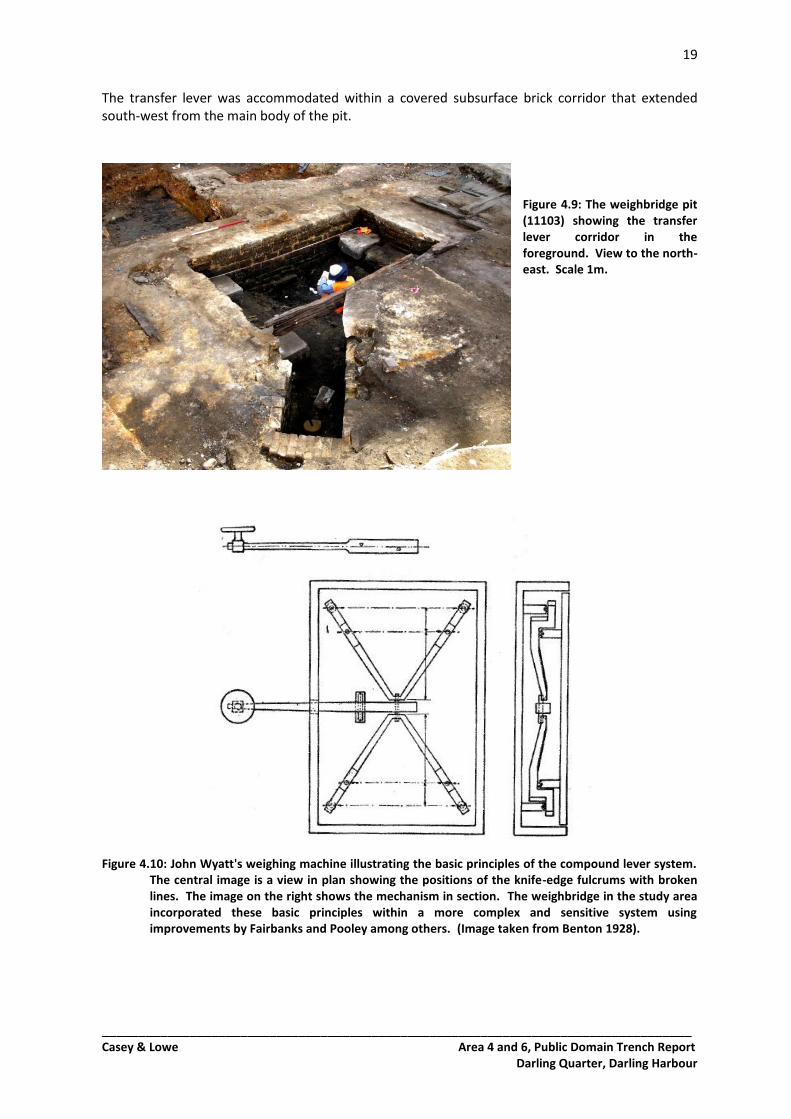
The transfer lever was accommodated within a covered subsurface brick corridor that extended south-west from the main body of the pit.
Figure 4.9: The weighbridge pit (11103) showing the transfer lever corridor in the foreground. View to the north-east. Scale 1m.
Figure 4.10: John Wyatt's weighing machine illustrating the basic principles of the compound lever system.
The central image is a view in plan showing the positions of the knife-edge fulcrums with broken lines. The image on the right shows the mechanism in section. The weighbridge in the study area incorporated these basic principles within a more complex and sensitive system using improvements by Fairbanks and Pooley among others. (Image taken from Benton 1928).
20
_________________________________________________________________________________ Casey & Lowe Area 4 and 6, Public Domain Trench Report
Darling Quarter, Darling Harbour
The weighbridge retained basic characteristics of John Wyatt's early machine from the 1740s4 (Figure 4.10) as well as improvements patented by E. & T. Fairbanks in 18375 and Henry Pooley in 18476. Undoubtedly, further adjustments had been added to the design by the time it was constructed in the 1860s, but these were not represented in the archaeological record. The angled corridor for the transfer lever appears to be related to the specific compound lever mechanism described by Fairbanks in the 1837 patent. The cut for the weighbridge was initiated in the fills 11113 and 11134. With only negligible variations, the cut had vertical sides and mimicked the shape of the structure. The cut for the main body of the weighbridge (11114) was rectangular in plan, measuring 4.6m x 2.92m. An amorphous deviation from the rectangular shape at the north-east corner created a sub-circular arc extending 200mm east. The cut was shallowest on the shortest sides, with a consistent depth of 980mm. On the longest sides the cut sloped from 980mm at the corners to at least 1.08m in the centre. Damage to the base of the cut after demolition disguised the original nature of the gradient. It may have originally been stepped. The deepest point of the cut described a north-south oriented channel that bisected the base of the cut and fed a drain in the north wall of the structure. Figure 4.11: The southern wall (11115) of the weighbridge pit showing the variety in block size and
coursing. View to the south. Scale 1m.
4 Dickinson 1944. See also Benton, 1928. 5 Fairbanks & Fairbanks 1837, US Patent No. 123. 6 Pooley 1847.
21
_________________________________________________________________________________ Casey & Lowe Area 4 and 6, Public Domain Trench Report
Darling Quarter, Darling Harbour
The cut for the corridor that accommodated the central transfer lever was also a vertical sided, rectangular cut that mimicked the shape of the structure. The cut (11140) described an elongated rectangle 910mm wide. Its eastern side was 2.16m long; its western was shorter at 1m, reflecting the angle at which the lever extended from the weighbridge. The cut was 1.23m deep with a flat base. The base of the cut exposed a reclamation fill of clay and crushed sandstone similar to 11113. The fill (11124) was a mix of white and yellow fine clay particles and red and white evenly crushed sandstone. It was present across the base of cuts 11140 and 11114. The main body of the weighbridge was constructed from neatly cut, rectangular sandstone blocks laid in up to seven courses (11115) (Figure 4.11). It described a rectangular subsurface space with sandstone lining 340mm wide. A top-to-base aperture of 1.40m width in the south-west corner was where the corridor for the transfer lever was connected. The sandstone blocks were laid against the walls of the cut and on the reclamation fill exposed at the base. Blocks of varying size were utilised in the structure, ranging from 320mm x 250mm x 50mm to 410mm x 340mm x 190mm. The blocks lined the cut in a single row with uneven coursing to accommodate the disparate sizes. At the top of the structure purpose cut blocks evened out the anomalies in the coursing to produce a horizontal surface at ground level. The sandstone was bonded with a coarse sand and shell mortar. It was buff-yellow in colour with rare charcoal flecks, fragments of shell of varying size and medium-grained sands. This mortar mix was also used to accommodate spaces between the blocks and the walls of the cut.
Figure 4.12: Sandstone pedestal (11116) viewed from above showing bolt-holes and corrosion symptoms.
This pedestal is in the south-east corner. The timber capping the southern wall can be seen at the left of the image. View to the west. Scale 500mm.
22
_________________________________________________________________________________ Casey & Lowe Area 4 and 6, Public Domain Trench Report
Darling Quarter, Darling Harbour
In each corner, a large rectangular-cut stone (11116) was keyed into the sandstone wall at the base (Figure 4.12). Each stone was a pedestal for a receiving block. Two corroded pins or bolts set into the stone and a blue-white flaky symptom of corrosion on the upper surface of the pedestals are likely to represent the base of cast iron receiving props. These props appeared to have first been used in a weighbridge by Henry Pooley in 1847.7 They took the weight of the platform when the weighbridge was not in use for extended periods and protected the knife-edges from unnecessary damage. The bolts that secured the receiving props were set at an interval of 410mm. It is also likely that these pedestals would have supported the device that would allow movement of the knife-edge for the rockers and ultimately the second order levers in each corner. The rockers were horizontal beams running north-south that the levers were fixed to. The operation of the weighbridge required that they were capable of describing an arc of movement as if on a hinge attached to the east or west wall. This was done with knife-edge fulcrums that in early weighbridges were fixed to the pedestals. Fairbanks' improvements patented a device that allowed movement of the fulcrums or suspended them from a fixed point at the end of the weighbridge. It is likely that such a device was incorporated into the receiving props, as no direct evidence was found on the sandstone pedestals. The stones were of different dimensions but had flat upper surfaces that were all within 50mm of each other.
Location Length Width Depth
NW corner 690mm 460mm 110mm
NE corner 720mm 530mm 210mm
SE corner 820mm 590mm 240mm
SW corner 900mm 560mm 170mm Figure 4.13: Dimensions of pedestals.
In the south-west corner, the pedestal had been modified to allow for movement of the transfer lever near the corridor entrance. This resulted in a clumsy-looking cut that removed the upper south-east corner of the rectangular stone. The stone was likely to have been modified after installation. The subsurface corridor (11137) for the transfer lever was largely constructed from re-used or surplus brick, excepting the area near the junction of the corridor and the main space (Figure 4.14). Sandstone blocks may have been employed at this location to maintain the integrity of the structure at the aperture. The bricks were laid in twelve courses in a stretcher bond. As with the main structure, the bricks lined the cut in a single row. They were bonded with the same sand/shell mortar as the sandstone blocks. The mortar was also used to accommodate discrepancies between the shape of the cut and the row of bricks. The bricks appeared to be predominantly sandstock (dark red with large iron inclusions) but the structure also contained extruded cut bricks with a single curved edge. These bricks were not purpose-made for the structure as the curved edge was turned inward to the face of the cut. However they exhibited no sign of previous use and may have been from surplus stock. They were yellow in colour and had similar characteristics to a London stock brick or marl. Dimensions of the sandstock bricks were 240mm x 110mm x 70mm. The extruded bricks measured 243mm x 110mm x 65-75mm. At the surface level, a single row of bricks laid stretch-to stretch created a flared lip on the walls at the far end of the corridor. This location was likely never covered and represented the connection point between the transfer lever and the above-ground measuring instrument.
7 Pooley 1847.
23
_________________________________________________________________________________ Casey & Lowe Area 4 and 6, Public Domain Trench Report
Darling Quarter, Darling Harbour
Figure 4.14: The entrance to the transfer lever corridor (11137) showing the purpose-cut blocks that direct
the angle of the structure. View to the south-east. Scale 1m.
Figure 4.15: The south-west end of the corridor (11137) showing shaped bricks that are likely to have been modified in situ to cancel interference with the steelyard. View to the west. Scale 1m.
Although subjected to demolition damage, there was evidence that the greater part of the corridor had been capped with large sandstone blocks (11136) to protect the transfer lever. An elongated and straight-cut rectangular block measuring 1.37m x 400mm x 250mm was still present above the eastern wall of the corridor with evidence that surface accumulations had built up around it. It was overhanging the corridor by 70mm. Other large pieces of sandstone had been broken and pushed into the corridor upon demolition (see below).
24
_________________________________________________________________________________ Casey & Lowe Area 4 and 6, Public Domain Trench Report
Darling Quarter, Darling Harbour
At the base of the weighbridge pit, a compact surface (11120) developed above the exposed reclamation clays 11124 (Figure 4.16). It consisted of iron oxide-rich sands and silt. It had the characteristics of an accumulation rather than a fill. Iron oxide precipitating through the above deposits became consolidated in small clusters throughout this accumulation.
Figure 4.16: Western end of the weighbridge pit showing the compact surface (11120) exposed between the pedestals. View to the west. Scale 1m.
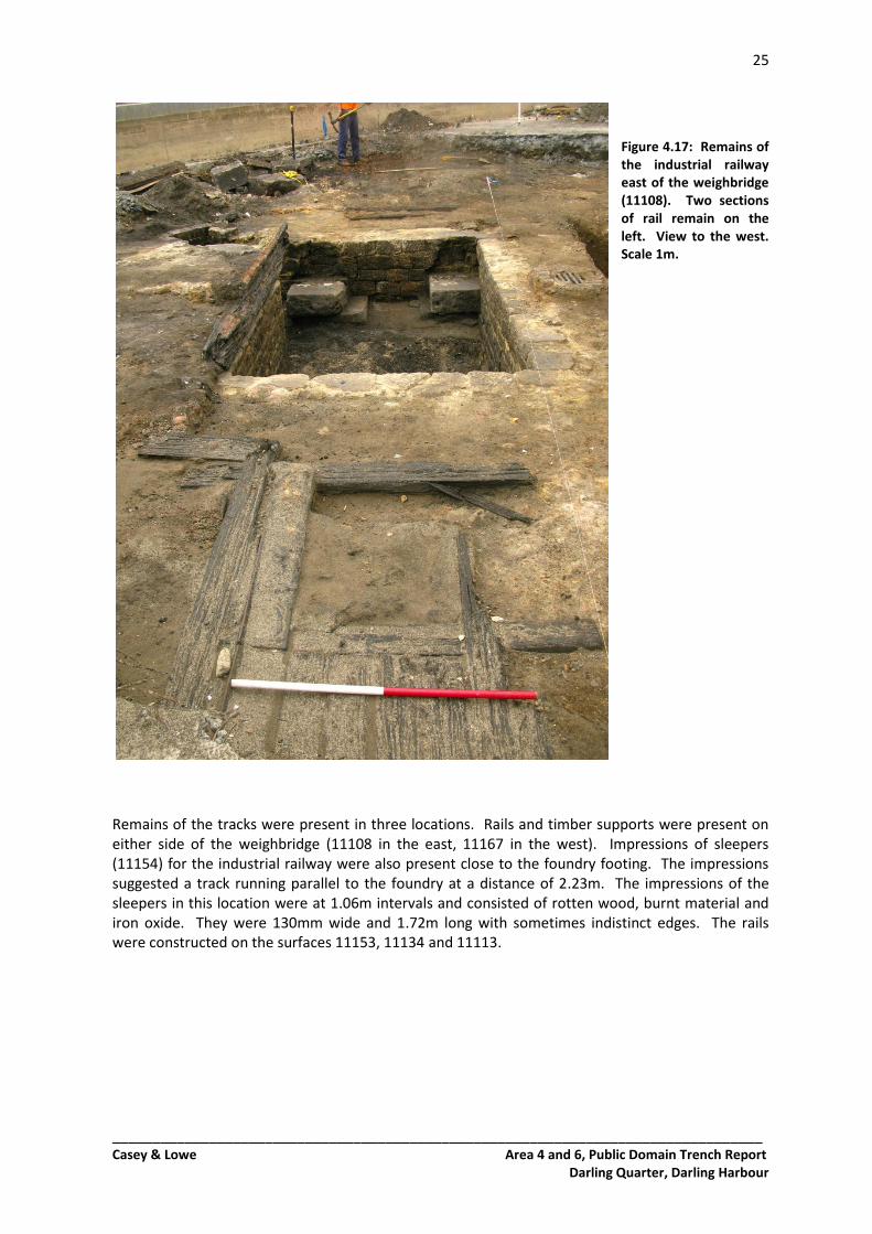
Rail-Tracks Cast iron rails facilitated the movement of wagons throughout the foundry and yard and west to the wharf. The rails were in 1.2m lengths and attached to long parallel timbers 250mm wide and 40mm thick that rested on perpendicular sleepers at 400mm intervals (Figures 4.17, 4.18). The rails were short and narrow at 50mm wide and 30mm high and cast with a baseplate 170mm wide and 50mm thick. The baseplate was attached to the timber with a single pin at each end. The rails were at an interval of 650mm and the intermediate space was covered with narrow timber boards 140m wide and 60mm thick. The resulting appearance was that of a narrow floating timber floor with parallel rails on each side.
25
_________________________________________________________________________________ Casey & Lowe Area 4 and 6, Public Domain Trench Report
Darling Quarter, Darling Harbour
Figure 4.17: Remains of the industrial railway east of the weighbridge (11108). Two sections of rail remain on the left. View to the west. Scale 1m.
Remains of the tracks were present in three locations. Rails and timber supports were present on either side of the weighbridge (11108 in the east, 11167 in the west). Impressions of sleepers (11154) for the industrial railway were also present close to the foundry footing. The impressions suggested a track running parallel to the foundry at a distance of 2.23m. The impressions of the sleepers in this location were at 1.06m intervals and consisted of rotten wood, burnt material and iron oxide. They were 130mm wide and 1.72m long with sometimes indistinct edges. The rails were constructed on the surfaces 11153, 11134 and 11113.
26
_________________________________________________________________________________ Casey & Lowe Area 4 and 6, Public Domain Trench Report
Darling Quarter, Darling Harbour
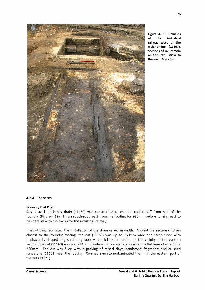
Figure 4.18: Remains of the industrial railway west of the weighbridge (11167). Sections of rail remain on the left. View to the east. Scale 1m.
4.6.4 Services Foundry Exit Drain A sandstock brick box drain (11160) was constructed to channel roof runoff from part of the foundry (Figure 4.19). It ran south-southeast from the footing for 980mm before turning east to run parallel with the tracks for the industrial railway. The cut that facilitated the installation of the drain varied in width. Around the section of drain closest to the foundry footing, the cut (11159) was up to 750mm wide and steep-sided with haphazardly shaped edges running loosely parallel to the drain. In the vicinity of the eastern section, the cut (11169) was up to 440mm wide with near-vertical sides and a flat base at a depth of 300mm. The cut was filled with a packing of mixed clays, sandstone fragments and crushed sandstone (11161) near the footing. Crushed sandstone dominated the fill in the eastern part of the cut (11171).
27
_________________________________________________________________________________ Casey & Lowe Area 4 and 6, Public Domain Trench Report
Darling Quarter, Darling Harbour
Figure 4.19: The run-off drain (11160) south of the foundry footing (right of image). The later addition of an iron pipe and the associated truncation of the drain can be seen in the left of the image. View to the west. Scale 1m.
At the junction of the drain and the footing a semi-cylindrical cut in the sandstone 160mm wide and 250mm deep may have accommodated a downpipe from the roof. The brick drain was constructed with a baseplate of cast iron. The sides were two courses of brick deep. The bricks were 240mm x 110mm x 70mm and cemented with a hard lime mortar that was coarse-grained and crumbled easily with applied force. The drain was 160mm deep and 160mm wide and was capped with a rectangular purpose-built iron plate that covered the drain along its 980mm journey south. The junction at the turn to the east had been damaged by later modifications and only a 900mm section of this part of the drain remained (11170). In this part of the drain the sides were only a single course high, although mortar on the upper side of some bricks suggested that a second course was once present. The base of the drain was a heavily corroded iron plate 300mm wide with an iron oxide crust that inflated its thickness to 90mm. The drain was filled with a dense but soft black silty material (11172). Inclusions were unsorted and consisted of fragments of brick, crushed sandstone and pockets of cream/pink clay. None of the inclusions amounted to any more than 3% of the material. It was 150mm deep and was present throughout the eastern extension of the drain. Other Services Ceramic pipes crossed the study area on north-south and east-west axes. Both pipes appeared to have been installed before the construction of the industrial railway but cut the early iron oxide-dominated yard surface 11102 (see below). The cuts were recorded under a single context number (11109) as were the fills (11110). Although the fills used in the cuts for the services were very similar, differences were detected that allowed the cuts to be distinguished at their intersection and their sequence established. The north-south pipe was installed first. It was detected at a depth of 483mm in TT1 but not further excavated. It ran parallel to the east wall of the weighbridge at a distance of 450mm. It was within a vertical-sided cut 350mm wide that had clear, straight edges and a sharp break of slope and sliced through several reclamation/levelling fills including 11111 and 11113 at the surface. The cut was
28
_________________________________________________________________________________ Casey & Lowe Area 4 and 6, Public Domain Trench Report
Darling Quarter, Darling Harbour
filled with a mixture of sand and clay that was red-brown in colour and tightly compacted. Sands were medium- to coarse-grained and occupied up to 30% of the fill. The east-west pipe ran parallel to the foundry footing at a distance of 4.25m. The cut for its installation was 750mm wide with clear, straight edges and vertical sides. The salt-glazed, earthenware pipe was detected in TT2 at a depth of 3.75m but not further excavated, and the base of the cut was not reached (Figure 4.20). The cut was filled with large pieces of sandstone rubble, orange-red clays and mid-brown medium- to coarse-grained sands.
Figure 4.20: West-facing section of TT2 showing the east-west service cut and fill (11109/11110) at the right of the image. View to the east. Scale 1m.
Weighbridge Drain Water accumulations within weighbridge pits were problematic and resulting corrosion and sediment interfered with the accuracy of the machine8. Any water that accumulated in the weighbridge pit was drained through an aperture at the base of the northern wall that fed into the east-west pipe described above. At the base of the pit, a depression along the central, north-south axis of the weighbridge formed the lowest part of the structure (Figure 4.21). This channelled any groundwater into the drain. The aperture (11123) described a rectangular space between two sandstone blocks at the base of the wall. It was 280mm wide and capped with a sandstone lintel 540mm long and 90mm thick that protruded 80mm from the wall. The drain was at least 180mm deep. The nature of the connection between it and the east-west pipe was not fully investigated.
8 Pooley 1847.
29
_________________________________________________________________________________ Casey & Lowe Area 4 and 6, Public Domain Trench Report
Darling Quarter, Darling Harbour
Figure 4.21: The north wall of the weighbridge pit showing the lintel for the drain (11123) protruding at the base of the wall. The pedestals are present in the upper left and lower right of the image. View to the north-west. Scale 1m.
Iron Water Pipe An iron pipe (11156) exited the foundry footing through an angled, cylindrical cut in the stone. The pipe had a diameter of 50mm and was at least 5m long. The cut that facilitated its installation (11155) was 140mm wide and filled with yellow clays and agglomerations of iron oxide (11157). It was not excavated. It cut the levelling fills 11153 and 11151. 4.6.5 Fills and Surface Accumulations Truncation of the site in the late twentieth century meant that yard surfaces within the study area were preserved in patchy islands that often evaded attempts to establish meaningful stratigraphic relationships. The earliest surface appeared to be a red-brown tightly compacted accumulation of coarse sands and iron oxide (11102). It was present in a skin of 5-20mm thickness in the vicinity of the weighbridge and covered the levelling fills in patches across the site. A light and dry crust concealed a blacker deposit beneath. Patches of industrial waste and broken river cobbles (11112) capped this accumulation in several isolated areas. The cobble fragments were up to 120mm long and tightly compacted within a matrix of soot and black industrial waste. The fill had been compacted to such a degree that cobbles were pressed into the levelling fill and iron oxide surface below. This surface covered the cuts for the service trenches and was also pressed into the fills. An additional sooty deposit (11158) was present in a small area abutting the foundry footing. It was located between and over cuts 11159 and 11155 and scattered to the area immediately south. It was a coarse-grained mixture of sand, soot and other very small industrial gravels. It may have once been part of the surface 11112, although no larger elements were visible.
30
_________________________________________________________________________________ Casey & Lowe Area 4 and 6, Public Domain Trench Report
Darling Quarter, Darling Harbour
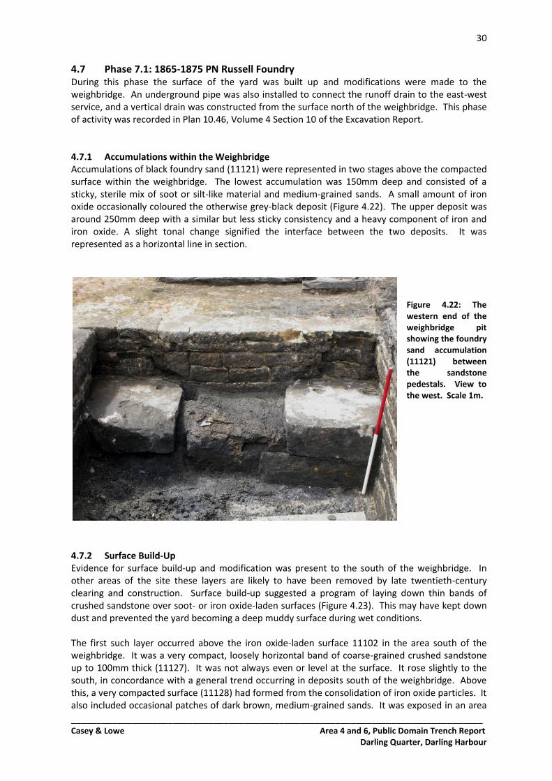
4.7 Phase 7.1: 1865-1875 PN Russell Foundry During this phase the surface of the yard was built up and modifications were made to the weighbridge. An underground pipe was also installed to connect the runoff drain to the east-west service, and a vertical drain was constructed from the surface north of the weighbridge. This phase of activity was recorded in Plan 10.46, Volume 4 Section 10 of the Excavation Report. 4.7.1 Accumulations within the Weighbridge Accumulations of black foundry sand (11121) were represented in two stages above the compacted surface within the weighbridge. The lowest accumulation was 150mm deep and consisted of a sticky, sterile mix of soot or silt-like material and medium-grained sands. A small amount of iron oxide occasionally coloured the otherwise grey-black deposit (Figure 4.22). The upper deposit was around 250mm deep with a similar but less sticky consistency and a heavy component of iron and iron oxide. A slight tonal change signified the interface between the two deposits. It was represented as a horizontal line in section.
Figure 4.22: The western end of the weighbridge pit showing the foundry sand accumulation (11121) between the sandstone pedestals. View to the west. Scale 1m.
4.7.2 Surface Build-Up Evidence for surface build-up and modification was present to the south of the weighbridge. In other areas of the site these layers are likely to have been removed by late twentieth-century clearing and construction. Surface build-up suggested a program of laying down thin bands of crushed sandstone over soot- or iron oxide-laden surfaces (Figure 4.23). This may have kept down dust and prevented the yard becoming a deep muddy surface during wet conditions. The first such layer occurred above the iron oxide-laden surface 11102 in the area south of the weighbridge. It was a very compact, loosely horizontal band of coarse-grained crushed sandstone up to 100mm thick (11127). It was not always even or level at the surface. It rose slightly to the south, in concordance with a general trend occurring in deposits south of the weighbridge. Above this, a very compacted surface (11128) had formed from the consolidation of iron oxide particles. It also included occasional patches of dark brown, medium-grained sands. It was exposed in an area
31
_________________________________________________________________________________ Casey & Lowe Area 4 and 6, Public Domain Trench Report
Darling Quarter, Darling Harbour
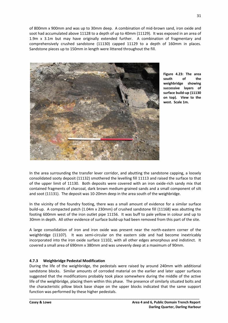
of 800mm x 900mm and was up to 30mm deep. A combination of mid-brown sand, iron oxide and soot had accumulated above 11128 to a depth of up to 40mm (11129). It was exposed in an area of 1.9m x 3.1m but may have originally extended further. A combination of fragmentary and comprehensively crushed sandstone (11130) capped 11129 to a depth of 160mm in places. Sandstone pieces up to 150mm in length were littered throughout the fill.
Figure 4.23: The area south of the weighbridge showing successive layers of surface build-up (11130 on top). View to the west. Scale 1m.
In the area surrounding the transfer lever corridor, and abutting the sandstone capping, a loosely consolidated sooty deposit (11132) smothered the levelling fill 11113 and raised the surface to that of the upper limit of 11130. Both deposits were covered with an iron oxide-rich sandy mix that contained fragments of charcoal, dark brown medium-grained sands and a small component of silt and soot (11131). The deposit was 10-20mm deep in the area south of the weighbridge. In the vicinity of the foundry footing, there was a small amount of evidence for a similar surface build-up. A compacted patch (1.04m x 230mm) of crushed sandstone fill (11168) was abutting the footing 600mm west of the iron outlet pipe 11156. It was buff to pale yellow in colour and up to 30mm in depth. All other evidence of surface build-up had been removed from this part of the site. A large consolidation of iron and iron oxide was present near the north-eastern corner of the weighbridge (11107). It was semi-circular on the eastern side and had become inextricably incorporated into the iron oxide surface 11102, with all other edges amorphous and indistinct. It covered a small area of 690mm x 380mm and was unevenly deep at a maximum of 90mm. 4.7.3 Weighbridge Pedestal Modification During the life of the weighbridge, the pedestals were raised by around 240mm with additional sandstone blocks. Similar amounts of corroded material on the earlier and later upper surfaces suggested that the modifications probably took place somewhere during the middle of the active life of the weighbridge, placing them within this phase. The presence of similarly situated bolts and the characteristic pillow block base shape on the upper blocks indicated that the same support function was performed by these higher pedestals.
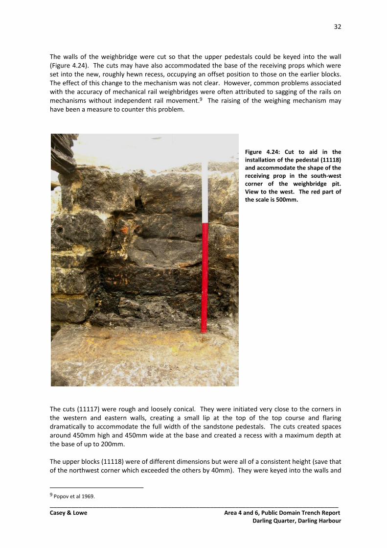
32
_________________________________________________________________________________ Casey & Lowe Area 4 and 6, Public Domain Trench Report
Darling Quarter, Darling Harbour
The walls of the weighbridge were cut so that the upper pedestals could be keyed into the wall (Figure 4.24). The cuts may have also accommodated the base of the receiving props which were set into the new, roughly hewn recess, occupying an offset position to those on the earlier blocks. The effect of this change to the mechanism was not clear. However, common problems associated with the accuracy of mechanical rail weighbridges were often attributed to sagging of the rails on mechanisms without independent rail movement.9 The raising of the weighing mechanism may have been a measure to counter this problem.
Figure 4.24: Cut to aid in the installation of the pedestal (11118) and accommodate the shape of the receiving prop in the south-west corner of the weighbridge pit. View to the west. The red part of the scale is 500mm.
The cuts (11117) were rough and loosely conical. They were initiated very close to the corners in the western and eastern walls, creating a small lip at the top of the top course and flaring dramatically to accommodate the full width of the sandstone pedestals. The cuts created spaces around 450mm high and 450mm wide at the base and created a recess with a maximum depth at the base of up to 200mm. The upper blocks (11118) were of different dimensions but were all of a consistent height (save that of the northwest corner which exceeded the others by 40mm). They were keyed into the walls and
9 Popov et al 1969.
33
_________________________________________________________________________________ Casey & Lowe Area 4 and 6, Public Domain Trench Report
Darling Quarter, Darling Harbour
were laid directly onto the lower pedestals (11116) with a coarse, low-grade sand mortar. The mortar crumbled easily, betraying only a minor cement quality with no visible lime. The mortar was also used to fill any cavities between the upper sandstone blocks and the crude edges of the accommodating cut.
The upper block in the north-east corner contained a rough, shallow and sloping cut (400mm x 190mm x 60mm) on its upper surface that was directed towards the transfer lever corridor. This depression would have accommodated exaggerated movement of the longest lever in the compound lever mechanism. The positioning of the lever indicated by the cut corresponds to Fairbanks' 1837 design. Figure 4.26: The pedestal stone (11118) in the north-east corner showing the bolt-holes and corrosion
associated with the receiving prop (left) and the diagonal, sloping cut (upper right).
4.7.4 Weighbridge Timber Retainer A large timber (11119) capped the southern wall of the weighbridge, preventing the surface build-up from encroaching on the structure (Figure 4.27). It may have been a replacement for an earlier timber, as it cut several of the surface fills south of the weighbridge.
34
_________________________________________________________________________________ Casey & Lowe Area 4 and 6, Public Domain Trench Report
Darling Quarter, Darling Harbour
Figure 4.27: The south wall of the weighbridge pit showing the timber capping (11119) acting as a retainer
against the fills beyond. View to the south. Scale 1m.
The cut (11135) had concave sides and was initiated in the surface 11130. It had a sharp break of slope at the surface. It was 350mm wide and 300mm deep. The cut was elongated and followed the shape and length of the timber. The cut may have been left exposed after the timber was secured, as it was filled with the surface accumulation 11131. The timber was 3.8m long, 270mm wide and 140mm deep and stood on its narrowest edge to maximise its height. It covered the length of the weighbridge including the transfer lever corridor. A large cut with rough, steep edges was located 710mm from the eastern end of the timber. It was trapezoidal in shape, cutting the timber to a depth of 170mm. It was 530mm long at the top and 470mm at the base. Its function was not clear and may have been inherited from a previous use. 4.7.5 Services During this phase the runoff drain from the foundry was connected to the large east-west pipe. A vertical brick drain leading from the surface to the same pipe was also installed north of the weighbridge. Both reduced the amount of water on the soot, clay and iron oxide-laden yard surface. This level of water management may have been necessary to prevent the sinking of the wagon tracks as there was no use of broken stone to aid the drainage process beneath the sleepers. Pipe for Run-off An underground cast iron pipe was used to connect the existing run-off drain to the large east-west pipe. The cast iron pipe had an interior diameter of 165mm. It ran from the point where the brick drain turned east, disturbing the bricks in that location. It was installed within a 750mm-wide cut that sloped down towards the large ceramic pipe. The cut was filled with a mixture of sandstone fragments and mid-brown, fine-grained sands. It is likely that the rails would have had to be partially removed to facilitate this. The short rail lengths (see above) would have made this operation relatively easy.
35
_________________________________________________________________________________ Casey & Lowe Area 4 and 6, Public Domain Trench Report
Darling Quarter, Darling Harbour
Surface Drain A vertical brick drain cut the exterior of the northern wall of the weighbridge and fed the large east-west service below (Figure 4.28). The drain was capped with a heavy iron grille and a hinged iron lid. The cut (11105) for the drain was loosely circular in plan, with maximum dimensions of 930mm x 900mm. It had vertical sides that partially cut the northern wall of the weighbridge, the fill of the service trench 11110 and the iron oxide surface 11102. The drain within was constructed from machine-made clay bricks heavy with ironstone inclusions (Figure 4.29). They measured 230mm x 110mm x 70mm and were laid in a stretcher bond to create a 280mm x 100mm narrow rectangular chamber leading down to the service below. A coarse, buff-coloured sand/shell mortar was used to bond the bricks. The aperture was widened at the top by stepping the bricks outward from the central column to create a 450mm x 400mm setting for the somewhat oversized, re-used grate. The grate was 630mm x 630mm and 100mm deep. The spaces between the grilles were 300mm long and 25mm wide. Capping the grille, a circular iron plate (11106) with evidence of hinging on the southern side had become fused with iron oxide to the grate itself. The plate had a diameter of 620mm and was 10mm thick. Within the cut, the drain was packed with red-orange clays and sandstone fragments (11126). Iron oxide was present within the fill near the surface. Patches of mid-brown, coarse-grained sands and crushed sandstone were in small quantities.
Figure 4.28: The grille of the drain (11106) after removal of the iron plate cap. The top of the north wall of the weighbridge pit can be seen at the top of the image. View to the south.
Figure 4.29: Machine removal of the large grate revealed the cut for the drain (11105) and its brick construction. The sandstone beyond is the cut north wall of the weighbridge pit. View to the south. Scale 1m.
36
_________________________________________________________________________________ Casey & Lowe Area 4 and 6, Public Domain Trench Report
Darling Quarter, Darling Harbour
4.8 Phase 7.2: 1875-1900 Abandonment and Demolition The closure of the foundry in 1875 meant that this sub-phase was a period of relative inactivity on the site as it remained vacant until the buildings were demolished in 1900. 4.8.1 Demolition Evidence of demolition was restricted to the weighbridge. In other areas, subsequent construction and reduction may have removed debris associated with the destruction of the foundry. 4.8.2 Weighbridge Fills Within the weighbridge, a large cut had removed the base surface and foundry sand accumulations from the centre of the structure. The cut (11122) was sub-ovoid in shape with loosely semi-circular and concave sides. It was initiated in the upper accumulation of 11121. It was 1.60m wide at the base and 1.95m wide at the top with a sharp break of slope. It was at least 950mm deep. Within the cut and covering the remaining areas of the weighbridge interior was a demolition fill of yellow-red clays, coarse buff coloured sands, sandstock brick, broken sandstone blocks, timber, iron fittings and small machine parts (11104) (Figure 4.30). The demolition fill was confined to the weighbridge interior. The corridor for the transfer lever had been filled with large and broken sandstone blocks that had likely once capped the corridor. Mid-brown sands and sandstock bricks also littered the fill.
Figure 4.30: Examples of bricks retrieved from the demolition material (11104) within the weighbridge pit. Scale 500mm.
37
_________________________________________________________________________________ Casey & Lowe Area 4 and 6, Public Domain Trench Report
Darling Quarter, Darling Harbour
4.9 Phases 8, 9, 10: Post-1900 4.9.1 Posthole An isolated posthole (11163) containing a large, rectangular post-pipe was present in the previous location of the wagon rails (near the foundry footing). The cut was sub-rectangular in plan, with dimensions of 400mm x 400mm. It was 310mm deep with concave sides and base and a sharp break of slope at the surface, cutting fills 11151 and 11111. It contained a rectangular post-pipe (11164) that was 110mm wide and 300mm long with vertical sides and a flat base at 310mm depth. The post was packed with a brown-black mix of coarse-grained sand, iron oxide and industrial waste (11165). As the post was substantially sized and in the location of the wagon tracks it is unlikely that it existed while the foundry was in use. While it is possible that the post may have belonged to an earlier phase, the presence of blue metal (11166) in the post-pipe suggested that the post was in situ until well after the life of the foundry and so the post has been attributed to the period after 1900. 4.9.2 Levelling Fills A process of reduction and levelling of the study area took place in the late twentieth century in association with bicentennial redevelopment of the area. Fills of clay, blue metal, dark sandy loam and sandstone (11101) were machine removed. These fills were sealed beneath the cement lining of the artificial lake created for the SegaWorld development.
4.10 Summary of Results Archaeological evidence corresponding to four phases of development at the Darling Walk site was present within the study area. Phase 5
Reclamation fills above the marine sands of Cockle Bay Reclamation and levelling fills were excavated and recorded to a depth of RL 0.65m within the study area. Largely horizontal banding coupled with contradicting tip lines suggested that the fills in this part of the site were spread to maximise coverage rather than dumped to maintain a pre-established height from the shoreline. These methods were different from those observed at similar RLs in Areas 6 and 8.
Phase 6
Brodie & Craig’s builders yard A surface corresponding to the yard area of Brodie & Craig was exposed in TT1. Although no structural features were present, the compact surface was littered with construction debris. An underground service dating to this phase of development cut the yard surface.
Resurfacing Evidence that the surface had been raised and levelled before the construction of the foundry was present across the site.
PN Russell Foundry Several surfaces associated with the foundry, a weighbridge and the remains of an industrial railway were present within the study area. Evidence of a more complex network of services was also found. Surfaces showed evidence of industrial use.
Phase 7
PN Russell Foundry Evidence of groundwater management on the site was present in the form of more complex drainage. Surfaces appeared to build up rapidly during this phase. Structural
38
_________________________________________________________________________________ Casey & Lowe Area 4 and 6, Public Domain Trench Report
Darling Quarter, Darling Harbour
evidence within the weighbridge suggested that modifications to the mechanism had occurred.
Demolition Evidence of demolition was found in the area of the weighbridge. The weighbridge mechanism had been removed and fill pushed into the vacant space. Demolition of the site occurred in 1900 after the land had been vacant for twenty five years.
Phase 10
Reduction, levelling and construction Modern fills associated with bicentennial developments capped the archaeological evidence of earlier phases. This material was removed by machine.
39
_________________________________________________________________________________ Casey & Lowe Area 4 and 6, Public Domain Trench Report
Darling Quarter, Darling Harbour
5.0 Balance Tanks (BT1 and BT2) Excavation – Area 4
5.1 Introduction Several areas of development impacts associated with the Public Domain civil works were identified outside the basement area. Most of these areas were within Area 4, the historical location of the PN Russell foundry. The construction of two balance tanks in the southern part of Area 4 was such area of impact. Overlays suggested that the tanks were within the yard area of the foundry and therefore likely impacting on less significant archaeological remains than that of the foundry buildings etc. The earliest archaeological evidence found in the Balance Tanks excavation area was comprised of wharf timbers and piers from the early 1850s and associated with Travers’ Wharf. Later phases were represented by reclamation fills and wharf consolidation of the early 1860s by PN Russell, including rails, a wagon turntable and associated yard surfaces, industrial deposits and evidence for a wooden structure of the 1870s. The excavation for the balance tanks was subject to archaeological investigation undertaken by Casey & Lowe in June and July 2010. 5.1.1 Study Area The Darling Walk development site is located within the Darling Harbour precinct, on the western edge of Sydney Central Business District. It is located on the eastern side of the harbour and is bound by Harbour Street to the east, Bathurst Street to the north, and Liverpool Street/Chinese Gardens to the south and Tumbalong Park to the west. The public domain area within the Darling Walk precinct is located to the west of the main structure and is adjacent to Tumbalong Park. The Public Domain area has been designated as a public open space which will be landscaped. Area 4 occupies a position that was originally below the high water mark. Reclamation work began in Area 4 in the early 1840s when the harbour developed as a predominantly industrial area. The consolidation and alterations to the harbour shoreline continued throughout the nineteenth century (Figure 5.1). Major redevelopments also occurred in the twentieth century, the last phase being in the 1980s when the Darling Harbour precinct was constructed and the nature and function of the area changed from industrial to leisure, entertainment with some retail and commercial.
Figure 5.1: Archaeological areas located on the 1886 MSW&D plan. The location of the balance tanks excavation area is indicated in blue. ‘Section 10, Metropolitan Detail Survey, City of Sydney’, 1886. Z/M Ser 4 811.17/1, Mitchell Library, SLNSW.
40
_________________________________________________________________________________ Casey & Lowe Area 4 and 6, Public Domain Trench Report
Darling Quarter, Darling Harbour
5.1.2 Archaeological Phases The Darling Walk study area has been divided into 10 main archaeological phases:
Phase 1 Natural Landscape
Phase 2 Aboriginal Occupation
Phase 3 1788 to 1820s Early Foreshore Activity and Property Boundaries
Phase 4 1820s to late 1830s Barker’s Mill and Lands
Phase 5 Late 1830s/Early 1840s Reclamation
Phase 6 1840s to 1860s Residential, Industrial Development and Reclamation
Phase 7 1860s to 1900 Residential and Industrial Development
Phase 8 1900s to 1920 Resumption and Railways
Phase 9 1920s to 1980s Railways and Commercial Development
Phase 10 1980s Demolition and Re-Development The phases and sub-phases relevant to the Public Domain Study area within Area 4 are as follows:
Phase 6.1 1840s to 1859 Industrial/ commercial development of Travers’ Wharf
Phase 6.2 1859 to 1865 Reclamation and wharf consolidation
Phase 7.1 1865 to 1875 PN Russell Foundry Forge workshop
Phase 7.2 1875 to 1900 Abandonment and Demolition 5.1.3 Excavation Program A program of archaeological investigation for the Balance Tanks (referred to as BT1 and BT2 throughout this report) excavation area was undertaken in June and July 2010. Excavation was confined to the area of impact associated with the construction of the two Balance Tanks. This corresponded to a section of Travers’ Wharf and the yard area of the PN Russell Foundry. Excavation was initiated with a 7 tonne excavator to remove the late twentieth-century concrete surface and the upper fills of the site. Further excavation was undertaken manually. The site was planned and recorded with reference to a site grid that was used in all areas of the wider Darling Walk project. The directors were Dr Mary Casey and Abi Cryerhall. The site was supervised and planned by Amanda Dusting. Site Assistants were Beau Spry, Mike Hincks and Nick Harrop. Machine excavation was by Christie Civil Contractors.
5.2 Historical Background to Area 4 Balance Tanks10 The study area lies to the west of the original high water mark of Thomas Barkers allotment of 6 acres 1 rood 32 perches (2.61ha), which he acquired in the 1820s. By the late 1820s Barker had his own wharf towards the southern boundary of his land and the shape of the shoreline was already changing. The area surrounding the study area was below the high water mark until the 1830s when the area was subjected to substantial reclamation by Barker. Within 20 years of its original acquisition, the shoreline of Barker’s Darling Harbour property including Area 4 was completely transformed with the reclamation of 3 acres 1 rood 8 perches (1.34ha) and the construction of extensive wharfage. The study area itself had not been included in the reclamation of the 1830s, and remained below the high water mark as part of a semicircular ‘basin’ to the north of Barkers jetty (Figure 5.2). By the 1840s, the area surrounding the study area occupied a dry parcel of land between the newly-created Barker Street and the wharfage at the edge of the bay. Although this land remained undeveloped, its potential for wharfage made it attractive to builders Hugh Brodie and Alexander
10 Summarised from Dr Rosemary Annable’s history of the Darling Walk area in Casey & Lowe 2008a.
41
_________________________________________________________________________________ Casey & Lowe Area 4 and 6, Public Domain Trench Report
Darling Quarter, Darling Harbour
Craig to whom it was sold in 1840. In 1844 Brodie & Craig then increased their holding, purchasing a second parcel of land from Barker located adjacent and to the south of the first allotment. In 1844, Brodie & Craig and Barker, agreed to rationalise their wharfage needs and built two new wharves. Barker’s original long jetty had disappeared (as the area around it became dry land), and was superseded by a curved, more substantial pier (incorporating parts of the old jetty) to the south and a new wharf was constructed for Brodie & Craig at the southern end of their property to the north of the ‘basin’. During the course of their ownership much land along the waterfront was reclaimed by Brodie & Craig including part of the ‘basin’ that was used as a slipway.
Figure 5.2: The area dashed in blue indicates the two allotments of Brodie & Craig and shows that the land
Brodie & Craig had purchased in 1840 did not include the study area, as the study area was located within the ‘basin’ (arrowed in blue ) which remained below the high water mark. E. J. H. Knapp ‘108 allotments the property of T. Barker Esquire to be sold by auction by M. Blackman 1842’ Subdivision Plans ZSP 811.1733/94, Mitchell Library, SLNSW.
42
_________________________________________________________________________________ Casey & Lowe Area 4 and 6, Public Domain Trench Report
Darling Quarter, Darling Harbour
Figure 5.3: Map shows the study area (arrowed in blue) as part of the ‘basin’ to the north of Barkers wharf with proposed additions marked to the north and south. ‘City of Sydney parish of St Andrew 3ac 1r 8p reclaimed from Darling Harbour by Thos’ Barker. Transmitted with description and letter No. 52/49dated 21
st October 1852. AO Map 5520, SRNSW.
By 1845 three brick terraced houses with detached kitchens had been built on the Barker Street frontage of Brodie & Craig’s land. The rest of the site at this time consisted of timber constructed workshops, a wood store, a blacksmith’s shop and a wharf. In the 1848 assessment, stables were also recorded.11 In 1853 Barker sold Area 5 (to the east of the study area) to J. L. Travers but retained ownership of the wharfage. Included in the sale to Travers was also a small portion of land at the south end of Barker Street that gave access to the waterfront in the ‘basin’ between the wharfage used by Brodie & Craig and Barker’s own wharf. Between 1853 and 1856 Travers constructed a wharf immediately to the north of Barkers wharf with a tramway/railway connecting it to his block of land to the north east on which there were a few small buildings. Presumably the land was being used for the storage of goods being shipped from the wharf. It is likely that the study area lies within the location of Travers’ Wharf. The 1855 survey showed the bulk of Area 4 as an empty yard to the south of several large sheds and the Barker Street houses (Figure 5.4).
11 Assessment Books Phillip Ward 1848 p 5 Nos. 465-468 (City of Sydney Archives)
43
_________________________________________________________________________________ Casey & Lowe Area 4 and 6, Public Domain Trench Report
Darling Quarter, Darling Harbour
Figure 5.4: Map showing the tramway extending from Travers property to the east (Area 5) indicated by dashed line, down to the newly constructed wharf to the north of Barkers wharf (arrowed). Detail from the 1855 Trigonometric Survey of Sydney CRS 502/19, Sheet 19. Historical Atlas of Sydney, City of Sydney Archives.
By March 1856 Travers’ holding was up for auction (it is not clear whether the property was sold at this time). In 1859 PN Russell Engineering acquired Brodie & Craig’s timber yard and wharfage and proceeded to develop their major foundry works on the site. By 1864, extensive building had taken place on the site, with a moulding shed and workshop constructed onto the back of the houses that were then used as offices. A large smith's shop was constructed on the previously empty yard area on the Barker Street frontage. Smaller stores and workshops littered the yard area along with cranes and tracks for wagons. By 1861 Travers land and wharf had been acquired by PN Russell & Co who were increasing their holdings in the area, having already begun construction on the west side of Barker Street (Figure 5.5). At first Travers’ old site was used by PN Russell & Co. as an office and yard but by 1865 quite substantial buildings had been constructed. By 1862 Travers’ Wharf had been incorporated into new wharfage on the main PN Russell site. It is during this period of consolidation that reclamation fills were put into the basin to start the process of infilling.
44
_________________________________________________________________________________ Casey & Lowe Area 4 and 6, Public Domain Trench Report
Darling Quarter, Darling Harbour
Figure 5.5: Plan showing Barkers pier and PN Russell & Co. Yard and wharf. By this time Travers’ Wharf had been incorporated into the PN Russell foundry (area dashed in blue). Plan for office use of Darling Harbour taken from plan of Chief Engineer, WG Bennett, September 1863, Crown Plan D.2 1628. AO Map 2630, SRNSW.
The 1865 survey shows the erecting shop, Smith shop and some sheds but does not include a large iron built workshop on the southern boundary of the PN Russell holding shown on both the 1875 Darling Harbour Frontage plan or the Percy Dove plan of 1880 (Figures 5.6, 5.7, 5.8). By 1869 PN Russell & Co. had constructed a railway carriage works on Travers land having won a five-year contract with NSW Railways. Further reclamation and changes to wharfage arrangements provided more land on the south side of the site. It was here that a large forge was built along the southern boundary on reclaimed land over what had once been Travers’ Wharf. A covered slip was installed to the north of the forge. During this time the study area and its surrounds became known as Russell’s Wharf. Following a series of labour disputes the PN Russell & Co. Foundry closed in 1875.
Figure 5.6: Map showing the incorporation of Travers’ Wharf and Barkers wharf into the main PN Russell Foundry wharfage. Also shown is the large smith shop (dashed) fronting Barker Street and the slipway (arrowed). 1865 Trigonometric Survey of Sydney Section E2 Sheet 1 Historical Atlas of Sydney, City of Sydney Archives.
45
_________________________________________________________________________________ Casey & Lowe Area 4 and 6, Public Domain Trench Report
Darling Quarter, Darling Harbour
Figure 5.7: Map showing the workshops and forge (arrowed) built as part of the PN Russell Foundry over
Russell’s Wharf - the study area (circled). Detail of ‘Darling Harbour Frontage Section No. 4’, dated 25 September 1875. Crown Plan P.26.574, sheet 1 of 11, AO Map 4708, SRNSW.
Figure 5.8: Map showing the timber wharf and iron workshop of the PN Russell Foundry with the
approximate location of the excavation area circled. Detail from H Percy Dove, Plans of Sydney, block 91, 1880, Historical Atlas of Sydney, City of Sydney Archives.
46
_________________________________________________________________________________ Casey & Lowe Area 4 and 6, Public Domain Trench Report
Darling Quarter, Darling Harbour
Although the foundry closed in 1875, the large workshops were still shown on the 1880 Percy Dove plan, including a workshop/forge constructed of iron which is located within the study area and was built on the consolidated wharfage. Following the company’s closure the premises appear to have been used as for wharfage and as stores. In 1891 John Findley was listed as the occupant, together with the NSW Government stores and the land was owned by the Darling Harbour Wharf & Investment Co.12 In 1900 the site was purchased by the Adelaide Steamship Co., and shortly after, the land was annexed by the NSW Government as part of the Darling Harbour Resumptions (Figure 5.9). The foundry buildings were demolished and the wharf was rebuilt, as part of the cleansing process, after the outbreak of plague. Because the site had seen little in the way of upkeep since the closure in 1875, it may have been seen as a significant harbourer of unhealthy elements. Figure 5.9: Resumption plan showing the study area. Plan L, Darling Harbour Resumptions, 1900, Historical
Atlas of Sydney, City of Sydney Archives.
In 1910 the northern half of the site was largely vacant with the exception of a stable in the northeast corner. The southern half was being utilised by the fuel merchants Warburton & Son. In 1918 the land was vested in the NSW Railway Commissioners and in the early 1920s the site was levelled, in-filled, and became an extension of the Darling Harbour Goods Yards. In 1982 the Darling Harbour Goods Yard was removed and the next incarnation of the area was to make way for the Darling Harbour development.
5.3 Excavation Results Overview The bulk excavation required for the installation of the two Balance Tanks had the potential to impact upon the archaeological resource. The Balance Tank trenches were numbered BT1 for the eastern-most trench and BT2 for the trench adjacent and to the west. A total of 28 context numbers were assigned to features and deposits within the study area during the archaeological testing phase; 14 in BT1 and 14 in BT2. Archaeological testing was carried out in two stages from 16 June to July 8 2010. Within the footprint of BT2 the remains of an early timber wharf were found
12 Assessment Books Denison Ward 1891 (City of Sydney Archives)
47
_________________________________________________________________________________ Casey & Lowe Area 4 and 6, Public Domain Trench Report
Darling Quarter, Darling Harbour
within a series of clay reclamation fills. Both BT1 and BT2 had a sequence of yard surfaces and levelling fills overlying reclamation fills as was evidence for a rail/tramway with associated tracks, and the footings for a late nineteenth-century building. These features and deposits were recorded on Plans 10.48 to 10.51 in Volume 4 Section 10 of the Excavation Report. Plan 10.51 provides an overview of Phases 6 and 7 in both Balance Tank areas, whereas Plans 10.48, 10.49 and 10.50 detail these phases within the individual areas. Overall site plan locations, the site grid and excavated areas are represented on Plan 10.1.
5.4 Phase 6.1: 1853 to 1856 Development – Travers’ Wharf JL Travers purchased much of Area 4 in 1853 when he bought the large portion of land to the east of Barker Street. Included in the purchase was a small holding on the waterfront at the end of Barker Street to the north of Barker’s Jetty where Travers constructed a wharf of his own between 1853 and 1856. Travers built his timber wharf in the ‘basin’ between Barker’s Jetty in the south and Brodie & Craig’s wharfage to the north. Travers’ Wharf originally included a tramway running from his property to the northeast of the study area down the length of the wharf to the harbour. Evidence for Travers’ timber wharf was found within BT2 and was recorded on Plan 10.50 (Vol 4 Section 10). Rails and a wagon turntable were discovered in BT1 and BT2; however, it is highly unlikely that they constitute part of Travers’ tramway unless they were removed during the reclamation process and reused in the later incarnation of the wharfage, as the rails were not found in conjunction with the remains of the timber wharf. 5.4.1 Timber Wharfage The earliest archaeological evidence found in the study area was located in BT2, where timber piles and crossbeams were revealed within reclamation clays and were assigned the context number 11328 (Figure 5.10). These timbers may relate to Travers’ Wharf, as it is likely that the early timbers and piers revealed were part of the wharf described in an advertisement in the Sydney Morning Herald in 1856 listing the impending auction of Travers’ Wharf and land:
That valuable City Property known as Travers Wharf, Darling Harbour. It is just near the foot of Bathurst Street and lies between Brodie and Craig’s Wharf and Barkers Jetty and has about 60 feet to Barker Street, 60 feet to Darling Harbour and there is a good Counting-house upon it. The wharf or jetty is most substantially constructed of the best Colonial Hardwood, the piles being Iron bark, and the flooring 3 inch gum planking. It extends 120 feet into the water with permission to carry it out to the line of Brodie and Craig’s Wharf.
There is about 9 feet of water off it at high tide.13
The remains of the wharfage (11328) consisted of a series of four piers on an east-west alignment with cross-beams on a north-south alignment. The piers, in the form of neatly sawn cylindrical logs, were placed at intervals of between 1.6m and 2m with an average diameter of 250mm. The crossbeams, with flat sawn upper and lower surfaces (averaging 310mm in diameter), were attached to the piers with mortise and tenon joints (Figure 5.11). The pier and cross beam located at the most easterly end of the trench also showed evidence of repair in the form of a large iron stake with a rectangular head (50 x 20mm) holding the damaged crossbeam in place. A rotted plank measuring 950mm x 90mm x 60mm appeared to be in situ within the fill to the south of the trench and may be a surviving upper timber of ‘3 inch gum planking’ (76.2mm). The upper timbers of the wharf appear to have been largely removed. This process of removal is likely to have occurred during the subsequent consolidation of the wharf when sold to the PN Russell foundry. The consolidation of the wharfage meant that the whole of the ‘basin’ was reclaimed through the dumping of reclamation fills around and under the extant piers and cross beams of the wharf.
13 Sydney Morning Herald, 11 March 1856 p.7.
48
_________________________________________________________________________________ Casey & Lowe Area 4 and 6, Public Domain Trench Report
Darling Quarter, Darling Harbour
Figure 5.10: View to the east showing wharf piers and timbers (arrows) within reclamation clays in BT2.
View to the east. Scale 1m.
Figure 5.11: Detail of wharf timber cross beam and mortise and tenon joint and remnant planking arrowed.
View to the south. Scale 500mm.
49
_________________________________________________________________________________ Casey & Lowe Area 4 and 6, Public Domain Trench Report
Darling Quarter, Darling Harbour
5.5 Phase 6.2: Late 1850s/Early 1860s – Reclamation and Wharf Consolidation Reclamation of a substantial portion of the land in Area 4 was undertaken by Thomas Barker. A parish plan dated 185214 showed that the reclaimed land attributed to him extended to a distance greater than 80m west of the original high water mark on the western side of Barker Street north of Thomas Street. Since these works were attributed to Thomas Barker, they must have taken place before 1840 when the land was sold to Brodie & Craig. The initial reclamation of the southern end of the study area was somewhat later than the area sold to Brodie & Craig in the north. The area in question was open water in the ‘basin’ to the north of Barkers jetty up until the construction of Travers’ Wharf in the early 1850s and not reclaimed until the wharf consolidation by PN Russell & Co. from the late 1850s. In 1859 PN Russell purchased Travers’ Wharf along with his land to the east of Barker Street. Photographs of Russell’s Wharf indicate that it was a combination of reclamation forming a yard surface with a wooden superstructure or curtain at the water’s edge (Figure 5.12). The reclamation was undertaken through a process of dumping clays and industrial fills into the water over the natural sands of the ‘basin’ and in and around the timbers of the wharf (Figure 5.14). Figure 5.12: Russell’s Wharf facing south. The timber curtain of the wharf is visible adjoining reclaimed
land forming the foundry yards. Uni of Sydney Archives, identifier G3_224_2739.
5.5.1 Reclamation Evidence Evidence for reclamation was exposed in BT2 within Test Trench 4 (TT4) (Figure 5.13). TT4 was excavated with a 7 tonne machine down to the water table. The earliest evidence for reclamation at the base of TT4 was context 11313. Context 11313 was a greyish black clayey silt with bands of industrial–type waste with inclusions of clinkers. The industrial waste material was visible at the base of TT4 but not excavated fully, it was excavated to a depth of 300mm as the rest of the fill was below the water table. Overlying 11313 was reclamation fill 11310 which was composed of a pinkish white sandy clay with frequent sandstone rubble and coarse sand, 300mm thick. The fill
14 'City of Sydney Parish of St Andrew 3ac 1r 8p Reclaimed from Darling Harbour by Thos. Barker'. Transmitted with description and letter no.52/49 dated 21 October 1852. AO Map 5520 (SRNSW)
50
_________________________________________________________________________________ Casey & Lowe Area 4 and 6, Public Domain Trench Report
Darling Quarter, Darling Harbour
was water logged and was sitting just above the water table. Above fill 11310 was 11309, a whitish orange clay with degrading iron stone inclusions, which caused orange staining within the clay. The fill had a maximum thickness of 120mm, was located at c. RL 1.2m and showed signs of having been water logged. The reclamation fills were also exposed surrounding Travers timber wharf as shown below (Figure 5.14).
Figure 5.13: South facing section of TT4 showing reclamation fills (11309 & 11310) above the water table (arrowed) and evidence for the first industrial working surface 11301/11320 (dashed line) directly overlying the reclamation fills. View to the north. Scale 2.6m.
Figure 5.14: Reclamation fills (arrowed) surrounding wharf timbers with surface 11301/11320 directly overlying. View to the east. Scale 1m.
51
_________________________________________________________________________________ Casey & Lowe Area 4 and 6, Public Domain Trench Report
Darling Quarter, Darling Harbour
Wharf Consolidation The study area had been transformed by the reclamation within the ‘basin’ which had resulted in the incorporation of Travers’ Wharf into Russell’s Wharf. As shown on the 1865 plan, Travers’ Wharf had been subsumed by the extension of Russell’s Wharf to the south, although the plan does not show any evidence of development at this stage. During the process of wharf consolidation the first yard surface of industrial soots and waste was formed over the reclamation, effectively sealing the wharf timbers beneath. At this time Travers’ tramway, which had been visible on the plan of 1855, seems to have been removed. It is possible that the tramway was removed then reinstated on the newly reclaimed wharfage, as evidence for a tramway or railway was found on top of reclamation fills and the first yard surface of Russell’s Wharf. 5.5.2 First Yard Surfaces and Levelling Fill Context (11320) located within BT1 was similar to yard surface (11113) near the weighbridge in the kiosk area to the north. Context 11320 was comprised of tightly compacted buff-coloured coarse grained sands containing small (5-7mm) fragments of sandstone, ironstone nodules (3-5 mm), and flecks of red and white clay (Figure 5.15). A shallow crust (30mm) of grey silts and small industrial gravels capped this layer. Gravels were pressed into the upper surface and silts had penetrated the first few millimetres of the fill. This surface material is most likely a shallow accumulation of the yard surface. Its shallowness may indicate that the surface was not exposed for an extended period. As this was the earliest surface found in the area, and was directly over reclamation fills, it is likely that this represents the first surface of the newly consolidated PN Russell foundry wharf. The wagon turntable (11316), part of the tramway, was on top of this surface (11320). Given that the tramway construction may have been undertaken quickly following the institution of the wharf, this may be why the surface appeared to have had little exposure. The surface was also found within BT2 and appeared as (11301) a compact surface c.50mm in depth. In BT2 the surface was comprised of black crushed industrial-type material likely to be coke or coal. Surface 11320 and 11301 sit directly over reclamation fills. Overlying surface 11320 and infilling irregularities was deposit 11329, a mostly black /grey consolidation of industrial gravels and black, burnt industrial waste with areas of fine grey silt and areas of firm agglomeration s of materials from above. Deposit 11329 represents a levelling fill for the timbers associated with the wagon turntable 11316 that sits directly on top of this deposit (Figure 5.15). Fill 11329 was only located directly below 11316 and is likely to have been a levelling fill to even out the surface below. It created a flat area on which to lay the timbers supporting the wagon turntable. The fill was thicker in the northeast at 30mm and thin in the southwest and filled a dip in the underlying surface 11320. The fill also shared characteristics with overlying fills (11325 and 11326). It is likely that the overlying levelling fills were put in place at the same time or close to the installation of the wagon turntable.
52
_________________________________________________________________________________ Casey & Lowe Area 4 and 6, Public Domain Trench Report
Darling Quarter, Darling Harbour
Figure 5.15: Yard surface 11320 with timbers of the wagon turntable 11316 to the right arrowed. View to
the west. Scale 2m.
5.5.3 Tramway - Railway15 In BT1 and BT2 a compact industrial surface (11314, 11303) was revealed at RL 1.40m in association with iron rails, timber sleepers and rail bearers, and the remains of an iron wagon turntable. It is possible that these rail/tramway remains were either newly installed by the PN Russell Foundry & Co. or were reused elements from Travers’ tramway. Travers’ tramway was only in existence from c.1853 and the sale of the property c.1856–1861 and it is likely that similar technologies and equipment were in use during this time as in the 1860s when the railway/tramway was constructed to the north in association with the PN Russell foundry complex. It is possible that the railway tracks were repaired or replaced as three phases of tracks were found in BT2. 5.5.4 Wagon turntable and timber base plate The remains of an industrial wagon turntable (11316) were uncovered in BT1 (Figures 5.16, 5.17). The wagon turntable mechanism 11316 consisted of a corroded circular iron plate (1.45m in diameter and 40-50mm thickness) with an iron pivot mechanism in the centre of the upper surface of the plate (Figure 5.16). The central pivot mechanism included five truncated radiating spurs with a central domed capping. The pivot mechanism was found to be fixed on the underside of the plate by a large bolt. The plate was found to directly overly a platform or levelling base comprised of a series of seven laid milled timbers (Figure 5.17). The platform timbers were c.50mm thick and 250mm wide and varied in length, graded to form a circle, with a minimum length of 500mm and maximum length of 1.55m in the middle. One timber showed evidence of reuse as it had two square holes (70mm x 60mm) cut through it. The timbers were found sitting directly on the levelling fill 11329.
15 Analysis for the main report in 2013 has resulted in the railway tracks being interpreted as part of Russell’s foundry as the location of the balance tanks excavation puts the track remains further north than the ones represented for Travers’ wharf on the 1855 plan. Also the phasing of the reclamation has put the tracks as post 1860. A. Cryerhall 2013.
53
_________________________________________________________________________________ Casey & Lowe Area 4 and 6, Public Domain Trench Report
Darling Quarter, Darling Harbour
Figure 5.16: Wagon turntable base with cog mechanism and the remains of the surrounding cylinder in BT1. View to the north. Scale 2m.
Figure 5.17: Detail of timber base revealed following the removal of wagon turntable facing south with 2m scale. One piece of timber shows evidence of reuse. View to the south. Scale 2m.
Comparison with examples of other industrial turntables suggested that only part of the device had survived. The circular plate and pivot mechanism would have originally been surrounded by a cylindrical curtain of iron (with a diameter of c.1.5m, 400mm in height and 30mm thickness). A small section of the cylinder survived in situ with the rest severely damaged by the cut of a later service trench, whereas the internal wheels, spokes and upper metal plate with its associated transverse rails did not survive and were not recovered during the current investigations. The upper surface of the extant circular plate was 500mm below the level of the compact industrial surface and rails (11314, 11303), which further suggested that when complete with an upper metal plate above the iron cylinder, the turntable would have functioned in conjunction with those rails and that surface. The rails found previously were identified with use of the weighbridge and the
54
_________________________________________________________________________________ Casey & Lowe Area 4 and 6, Public Domain Trench Report
Darling Quarter, Darling Harbour
transport of goods by rail in wagons or trolleys from the PN Russell foundry and workshops down to the wharves. It is likely that the wagon turntable, rails and associated surface would also have facilitated such movement of goods around the foundry yard and workshops. The remains of the wagon turntable, including the circular plate with attached pivot, the surviving section of the iron cylinder, a rail and a timber slab were removed and taken as examples to be archived and stored by the Sydney Harbour Foreshores Authority.
Figure 5.18: Example of a wagon turntable for railways showing transverse rails and wheeled turning mechanism. Benton 1928.
5.5.5 Levelling fills between yard surfaces Between the first yard surface in BT1 (11320) and the next yard surface (11314) were a series of levelling fills, these may have been laid to raise the surface level in order to accommodate the wagon turntable (Figure 5.19). The levelling fills between the two surfaces sloped gently to the west, thinning as they approached the harbour and the timber wharf. The levels were raised to correspond to that of the wagon turntable. It is likely that the levelling fills and wagon turntable were put in place at the same time. The following table is a summary of the levelling fills between surface 11320 and 11314.
55
_________________________________________________________________________________ Casey & Lowe Area 4 and 6, Public Domain Trench Report
Darling Quarter, Darling Harbour
Context Description Thickness
11321 The fill was comprised of poorly mixed orange and pink clays containing large fragments (100-150mm) of soft and degraded sandstone and iron nodules in a gently sloping tip line from south to north. The fill was recorded in the north facing section. The fill extended from the southern limit of excavation across the trench to the north gently sloping to the north west. The fill was laid directly over surface 11320 and peeled off easily.
Max 210mm
11322 The fill was comprised of mustard coloured homogeneous clays, with a small sand component, containing small ironstone nodules. Gently sloping tip line to the west, the fill appears only in the east half of BT1 in the north facing section.
Max 800mm
11323 The fill was comprised of a mix of white and pink clays, grey and brown medium grained sands with fragments of soft (degraded sandstone throughout). Appears in the western half of the north facing section with a gently sloping tip line to the north.
Max 160mm
11325 The fill was comprised of a loosely consolidated mix of pinkish brown industrial gravels and black, burnt industrial waste. The fill appeared in the northern part of the east-facing section and in large patches across the trench. The fill sloped gently down to the north.
Max 110mm
11326 The fill was comprised of non-stratigraphic agglomerations of iron and iron oxide that appeared throughout layer 11325 adhering to the base of 11314. These were large agglomerations of iron and iron oxide which appear to have leached from above and consolidated within the loosely compacted 11325 which was overlying the tightly compacted 11320. The fill was prominent surrounding the wagon turntable.
Table 1: Summary of levelling fills between surfaces
Figure 5.19: View of north facing section showing levelling fills between surface 11320 and11314 (arrowed).