22

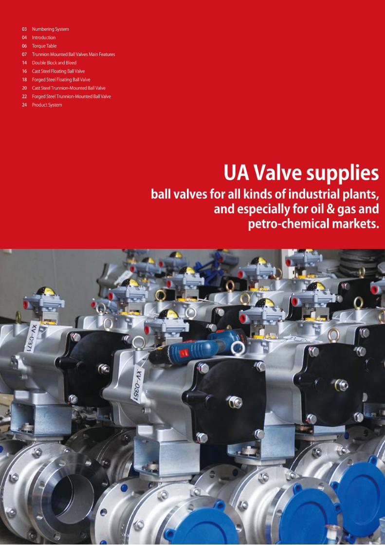
UA Valve suppliesball valves for all kinds of industrial plants,
and especially for oil & gas and petro-chemical markets.
Numbering System
Introduction
Torque Table
Trunnion Mounted Ball Valves Main Features
Double Block and Bleed
Cast Steel Floating Ball Valve
Forged Steel Floating Ball Valve
Cast Steel Trunnion-Mounted Ball Valve
Forged Steel Trunnion-Mounted Ball Valve
Product System
03
04
06
07
14
16
18
20
22
24

Numbering System
- -
Construction Bore Connections Operating BonnetDesign Body Material Pressure RatingTrim Material
Construction : Side Entry Pressure Rating : 1500 LBS
Bonnet : Standard
Bore : Full Trim Material : Inconel
Connections : Ring Joint Body Material : Inconel
Operating : Bare Stem Design : Trunnion
- -S TF 8RJ HB 5 S
Bonnet
S
E
Standard
Extension
Construction
T
S
Top Entry
Side Entry
Bore
F
R
Full
Reduced
Connections
RF
SW
TH
RJ
BW
SP
Raised Face
Ring Joint
Socket Weld
Butt Weld
Threaded
Special
Operating
P
G
B
M
L
X
Pneumatic Actuator
Motor Actuator
Gear Operating
Lever Handle
Bare Stem
Special
Design
F
T
Floating
Trunnion
Body Material
1
3
5
7
2
4
6
8
9
A105 / WCB
LF2 / LCC
CF8
CF8M
Duplex
Al-Bronze
Alloy 20
Hastelloy
Inconel
Trim Material
A
C
E
G
B
D
F
H
I
S
CS + ENP
304 SS
316 SS
Duplex
Al-Bronze
316 SS + TC
Alloy 20
Hastelloy
Inconel
Special
Pressure Rating
1
3
5
7
2
4
6
150 LBS
300 LBS
600 LBS
900 LBS
1500 LBS
2500 LBS
4500 LBS
fluid control solution
03
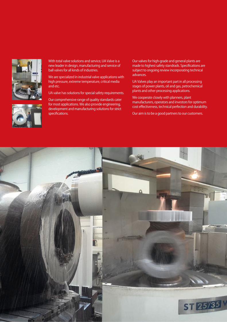
With total valve solutions and service, UA Valve is a new leader in design, manufacturing and service of ball valves for all kinds of industries.
We are specialized in industrial valve applications with high pressure, extreme temperature, critical media and etc.
UA valve has solutions for special safety requirements.
Our comprehensive range of quality standards cater for most applications. We also provide engineering, development and manufacturing solutions for strict specifications.
Our valves for high-grade and general plants are made to highest safety standrads. Specifications are subject to ongoing review incorporating technical advances.
UA Valves play an important part in all processing stages of power plants, oil and gas, petrochemical plants and other processing applications.
We cooperate closely with planners, plant manufacturers, operators and investors for optimum cost effectiveness, technical perfection and durability.
Our aim is to be a good partners to our customers.
fluid control solution
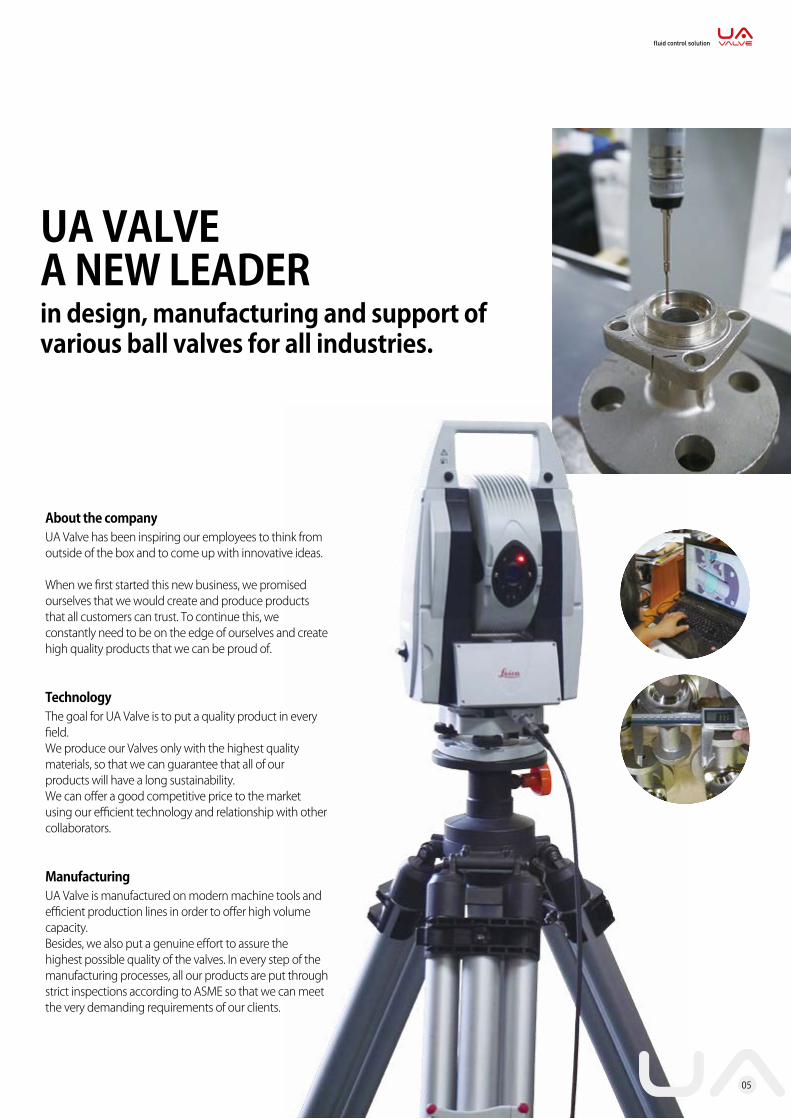
About the companyUA Valve has been inspiring our employees to think from outside of the box and to come up with innovative ideas.
When we first started this new business, we promised ourselves that we would create and produce products that all customers can trust. To continue this, we constantly need to be on the edge of ourselves and create high quality products that we can be proud of.
Technology The goal for UA Valve is to put a quality product in every field.We produce our Valves only with the highest quality materials, so that we can guarantee that all of our products will have a long sustainability.We can offer a good competitive price to the market using our efficient technology and relationship with other collaborators.
ManufacturingUA Valve is manufactured on modern machine tools and efficient production lines in order to offer high volume capacity.Besides, we also put a genuine effort to assure the highest possible quality of the valves. In every step of the manufacturing processes, all our products are put through strict inspections according to ASME so that we can meet the very demanding requirements of our clients.
UA VALVEA NEW LEADERin design, manufacturing and support of various ball valves for all industries.
05

Valve Rating 150 300 600 900 1500 2500
Valve Max. W.P. 275 psi 19bar 720 psi 50bar 1440 psi 100bar 2160 psi 150bar1 ½” 40 40 50 80 140 240 420
2” 50 50 72 119 202 322 590
3” 80 60 93 185 349 466 1,130
4” 100 226 298 466 781 1,116 1,800
6” 150 640 789 1,046 1,479 2,456
8” 200 1,021 1,388 2,309 3,293 5,462
10” 250 1,458 2,027 3,057 4,699 8,847
12” 300 2,004 2,788 4,483 7,193 12,698
14” 350 2,218 3,795 6,826 9,124 16,103
16” 400 3,095 5,300 8,686 13,023 20,546
18” 450 4,166 6,956 13,012 19,207 31,062
20” 500 5,320 9,442 17,562 26,008 40,282
22” 550 8,036 11,020 19,411 32,002 46,074
24” 600 8,795 14,792 26,238 40,151 66,290
26” 650 11,950 20,341 33,987 47,634
28” 700 14,513 25,609 42,238 59,407
30” 750 16,671 24,918 44,105 51,708
Torque Table (Cast Steel Floating & Trunnion-Mounted Ball Valve)
Method of Calculation FlowThe flow coefficient Cv of a valve is the flow rate of water(gallons/minute) through a fully opened valve with a pressure drop of 1 psi across the valve.To find the flow of liquid through the valve from the valve from the Cv, use the following formulas.
Liquid FlowQL = Cv(P/G)1/2
△P=Differential pressure across the valve (psig)QL = Flow rate of liquid(gal./min)G = Specific gravity of liquid (for water, G=1)
Gas FlowQg = 61Cv(P2P/g)1/2 (For non-critical flow, P2/P<1.0)P2 = Outlet pressure(psia)QL = Flow rate of gas (CFH at STP)G = Specific gravity of gas (for air, g=1.0)
Trunnion-Mounted Ball ValveBall Valve Flow Coefficient Cv Specification Table
Size Pressure Grade
mm in 150 300 600 900 1500 250015 1/2 25 25 22 20 20 24
20 3/4 55 55 47 44 44 53
25 1 94 94 78 74 74 92
40 1 1/2 260 260 260 188 188 211
50 2 441 406 376 351 351 283
80 3 1,103 973 933 883 833 600
100 4 2,012 1,762 1,687 1,642 1,562 1,160
150 6 3,721 3,719 3,396 3,841 3,635 2,590
200 8 7,061 6,876 6,381 7,253 6,759 4,795
250 10 11,476 11,266 10,281 11,801 10,860 7,410
300 12 17,027 16,722 15,527 17,407 15,512 10,433
350 14 20,836 20,196 19,316 21,032 19,490
400 16 28,060 27,258 25,950 28,591 26,164
450 18 36,253 35,638 33,798 37,718 34,973
500 20 46,330 45,188 42,723 48,672 45,658
550 22 56,388 56,378 55,788 40,184 35,860600 24 69,399 67,919 63,874 47,884 41,733650 26 59,012 59,012 59,012 56,076700 28 94,436 92,111 88,191 65,110750 30 110,672 108,047 102,562 74,610800 32 124,879 120,734 115,084 84,977850 34 101,307 101,307 101,307 96,020900 36 158,878 152,651 144,018 107,487
1000 40 194,341 194,341 189,5711050 42 275,260 275,260 275,2601200 48 364,180 364,180 347,0801400 55 529,430 529,430 520,500
Notes 1. All the sizes are in full port2. Pressure ratings are according to API 6D
06
UNIT(N/m)
Trunnion Mounted Ball Valves Main Features
WhyTrunnionMounted ball?
07
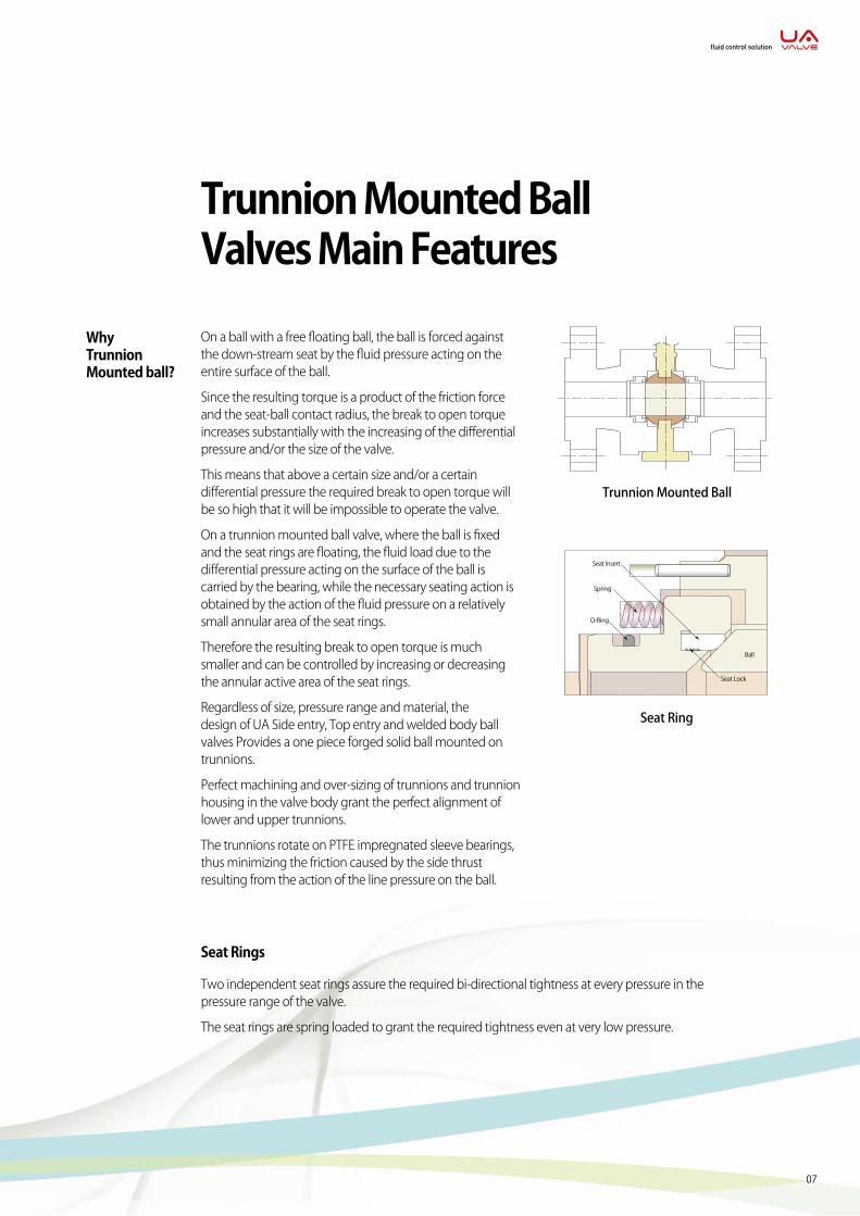
On a ball with a free floating ball, the ball is forced against the down-stream seat by the fluid pressure acting on the entire surface of the ball.
Since the resulting torque is a product of the friction force and the seat-ball contact radius, the break to open torque increases substantially with the increasing of the differential pressure and/or the size of the valve.
This means that above a certain size and/or a certain differential pressure the required break to open torque will be so high that it will be impossible to operate the valve.
On a trunnion mounted ball valve, where the ball is fixed and the seat rings are floating, the fluid load due to the differential pressure acting on the surface of the ball is carried by the bearing, while the necessary seating action is obtained by the action of the fluid pressure on a relatively small annular area of the seat rings.
Therefore the resulting break to open torque is much smaller and can be controlled by increasing or decreasing the annular active area of the seat rings.
Regardless of size, pressure range and material, the design of UA Side entry, Top entry and welded body ball valves Provides a one piece forged solid ball mounted on trunnions.
Perfect machining and over-sizing of trunnions and trunnion housing in the valve body grant the perfect alignment of lower and upper trunnions.
The trunnions rotate on PTFE impregnated sleeve bearings, thus minimizing the friction caused by the side thrust resulting from the action of the line pressure on the ball.
Trunnion Mounted Ball
Seat Ring
Seat Insert
Spring
O-Ring
Ball
Seat Lock
Seat Rings
Two independent seat rings assure the required bi-directional tightness at every pressure in the pressure range of the valve.
The seat rings are spring loaded to grant the required tightness even at very low pressure.
fluid control solution
08
Emergency sealant injection
The design and the built-in quality of UA Trunnion Mounted ball valves do not require the use of a sealant injection to grant the perfect tightness, and therefore the provision for emergency grease injection in the seat sealing area is considered as an option available on customer request only.
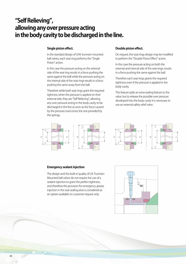
Double piston effect.
On request, the seat rings design may be modified to perform the “Double Piston Effect” action.
In this case the pressure acting on both the external and internal side of the seat rings, results in a force pushing the same against the ball.
Therefore each seat rings grants the required tightness even if the pressure is applied in the body cavity.
This feature adds an extra sealing feature to the valve, but to release the possible over pressure developed into the body cavity it is necessary to use an external safety relief valve.
Single piston effect.
In the standard design of UAV trunnion mounted ball valves, each seat ring performs the “Single Piston” action.
In this case the pressure acting on the external side of the seat ring results in a force pushing the same against the ball while the pressure acting on the internal side of the seat rings results in a force pushing the same away from the ball.
Therefore while both seat rings grant the required tightness when the pressure is applied on their external side, they are “Self Relieving”, allowing any over pressure acting in the body cavity to be discharged in the line as soon as the force caused by the pressure overcomes the one provided by the springs.
A C B D E F A C B D E F
“Self Relieving”, allowing any over pressure acting in the body cavity to be discharged in the line.
09
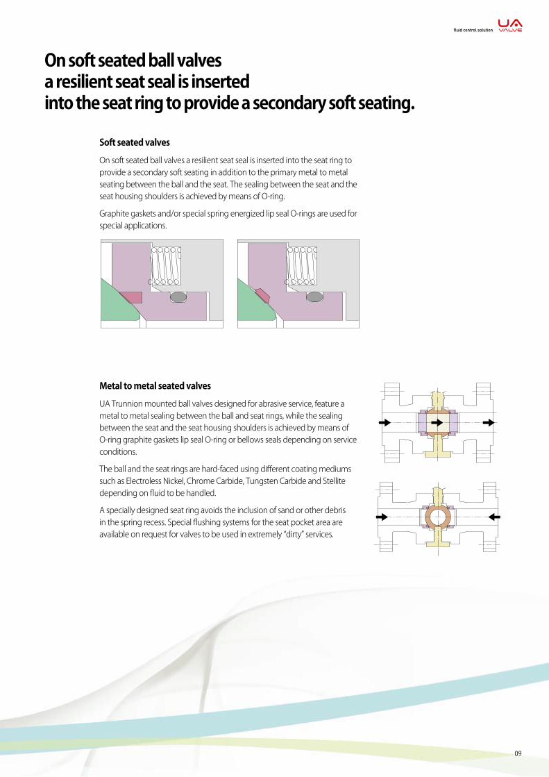
Soft seated valves
On soft seated ball valves a resilient seat seal is inserted into the seat ring to provide a secondary soft seating in addition to the primary metal to metal seating between the ball and the seat. The sealing between the seat and the seat housing shoulders is achieved by means of O-ring.
Graphite gaskets and/or special spring energized lip seal O-rings are used for special applications.
Metal to metal seated valves
UA Trunnion mounted ball valves designed for abrasive service, feature a metal to metal sealing between the ball and seat rings, while the sealing between the seat and the seat housing shoulders is achieved by means of O-ring graphite gaskets lip seal O-ring or bellows seals depending on service conditions.
The ball and the seat rings are hard-faced using different coating mediums such as Electroless Nickel, Chrome Carbide, Tungsten Carbide and Stellite depending on fluid to be handled.
A specially designed seat ring avoids the inclusion of sand or other debris in the spring recess. Special flushing systems for the seat pocket area are available on request for valves to be used in extremely “dirty” services.
On soft seated ball valves a resilient seat seal is inserted into the seat ring to provide a secondary soft seating.
fluid control solution
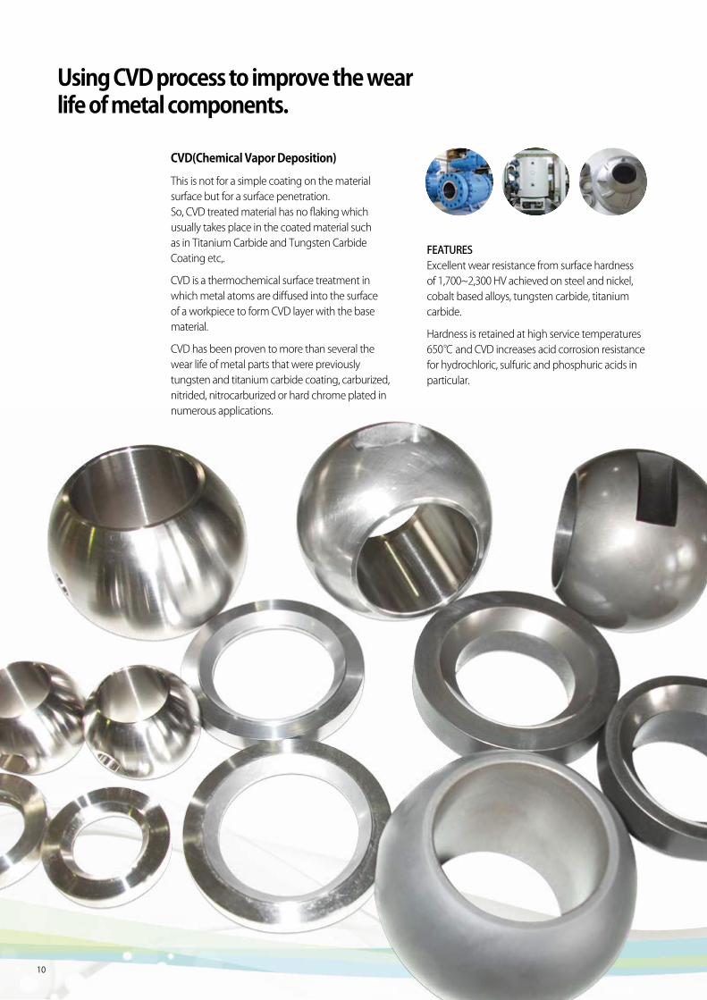
CVD(Chemical Vapor Deposition)
This is not for a simple coating on the material surface but for a surface penetration. So, CVD treated material has no flaking which usually takes place in the coated material such as in Titanium Carbide and Tungsten Carbide Coating etc,.
CVD is a thermochemical surface treatment in which metal atoms are diffused into the surface of a workpiece to form CVD layer with the base material.
CVD has been proven to more than several the wear life of metal parts that were previously tungsten and titanium carbide coating, carburized, nitrided, nitrocarburized or hard chrome plated in numerous applications.
FEATURESExcellent wear resistance from surface hardness of 1,700~2,300 HV achieved on steel and nickel, cobalt based alloys, tungsten carbide, titanium carbide.
Hardness is retained at high service temperatures 650℃ and CVD increases acid corrosion resistance for hydrochloric, sulfuric and phosphuric acids in particular.
Using CVD process to improve the wear life of metal components.
10
11
fluid control solution
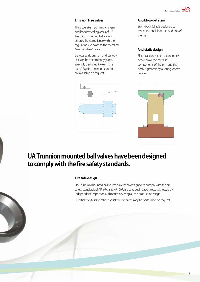
Emission free valves
The accurate machining of stem and bonnet sealing areas of UA Trunnion mounted ball valves assures the compliance with the regulations relevant to the so called “emission free” valve.
Bellows seals on stem and canopy seals on bonnet to body joints, specially designed to reach the “zero” fugitive emission condition are available on request.
Anti-static design
Electrical conductance continuity between all the metallic components of the trim and the body is granted by a spring loaded device.
Anti blow-out stem
Stem-body joint is designed to assure the antiblowout condition of the stem.
Fire safe design
UA Trunnion mounted ball valves have been designed to comply with the fire safety standards of API 6FA and API 607, fire safe qualification tests witnessed by independent inspection authorities covering all the production range.
Qualification tests to other fire safety standards may be performed on request.
UA Trunnion mounted ball valves have been designed to comply with the fire safety standards.
12
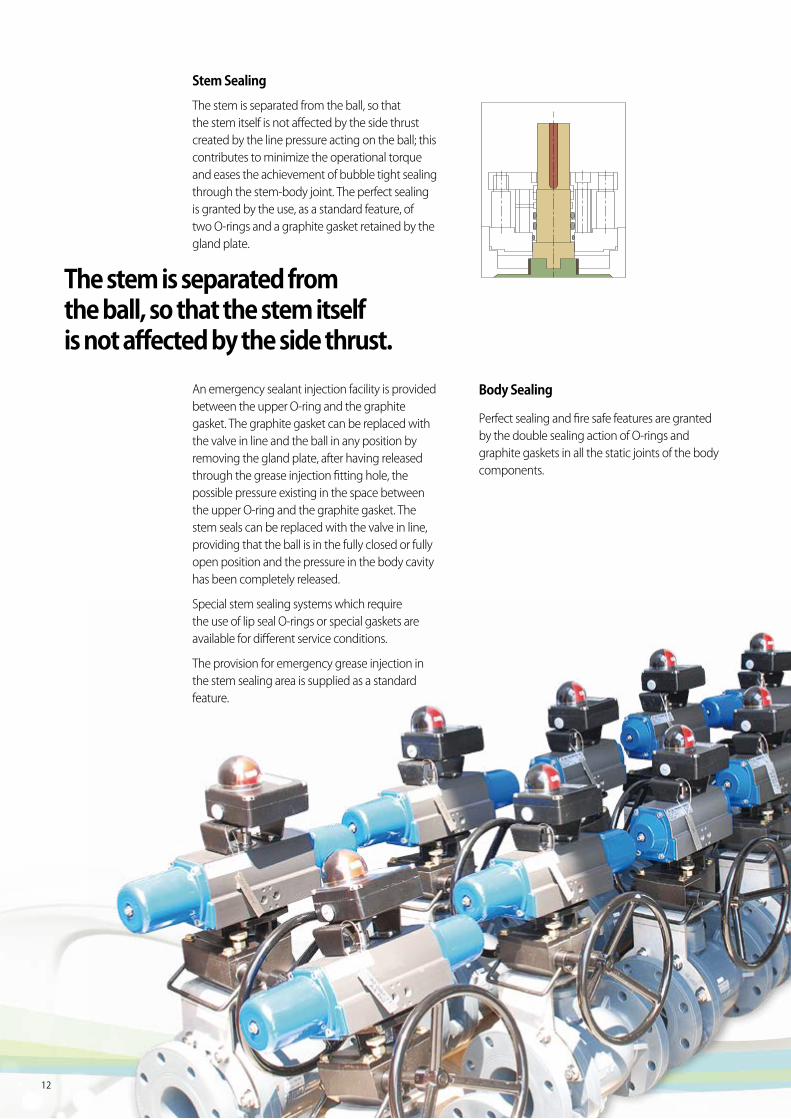
Stem Sealing
The stem is separated from the ball, so that the stem itself is not affected by the side thrust created by the line pressure acting on the ball; this contributes to minimize the operational torque and eases the achievement of bubble tight sealing through the stem-body joint. The perfect sealing is granted by the use, as a standard feature, of two O-rings and a graphite gasket retained by the gland plate.
An emergency sealant injection facility is provided between the upper O-ring and the graphite gasket. The graphite gasket can be replaced with the valve in line and the ball in any position by removing the gland plate, after having released through the grease injection fitting hole, the possible pressure existing in the space between the upper O-ring and the graphite gasket. The stem seals can be replaced with the valve in line, providing that the ball is in the fully closed or fully open position and the pressure in the body cavity has been completely released.
Special stem sealing systems which require the use of lip seal O-rings or special gaskets are available for different service conditions.
The provision for emergency grease injection in the stem sealing area is supplied as a standard feature.
Body Sealing
Perfect sealing and fire safe features are granted by the double sealing action of O-rings and graphite gaskets in all the static joints of the body components.
The stem is separated from the ball, so that the stem itself is not affected by the side thrust.
13
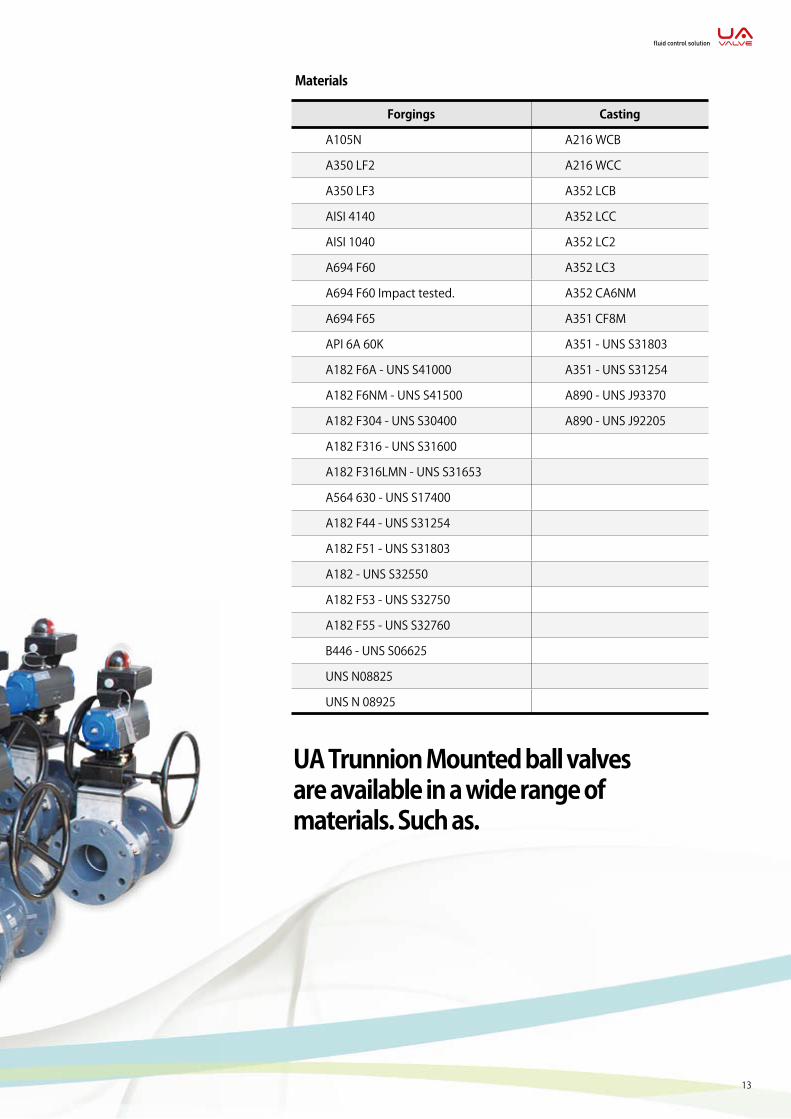
Materials
Forgings Casting
A105N A216 WCB
A350 LF2 A216 WCC
A350 LF3 A352 LCB
AISI 4140 A352 LCC
AISI 1040 A352 LC2
A694 F60 A352 LC3
A694 F60 Impact tested. A352 CA6NM
A694 F65 A351 CF8M
API 6A 60K A351 - UNS S31803
A182 F6A - UNS S41000 A351 - UNS S31254
A182 F6NM - UNS S41500 A890 - UNS J93370
A182 F304 - UNS S30400 A890 - UNS J92205
A182 F316 - UNS S31600
A182 F316LMN - UNS S31653
A564 630 - UNS S17400
A182 F44 - UNS S31254
A182 F51 - UNS S31803
A182 - UNS S32550
A182 F53 - UNS S32750
A182 F55 - UNS S32760
B446 - UNS S06625
UNS N08825
UNS N 08925
UA Trunnion Mounted ball valves are available in a wide range of materials. Such as.
fluid control solution
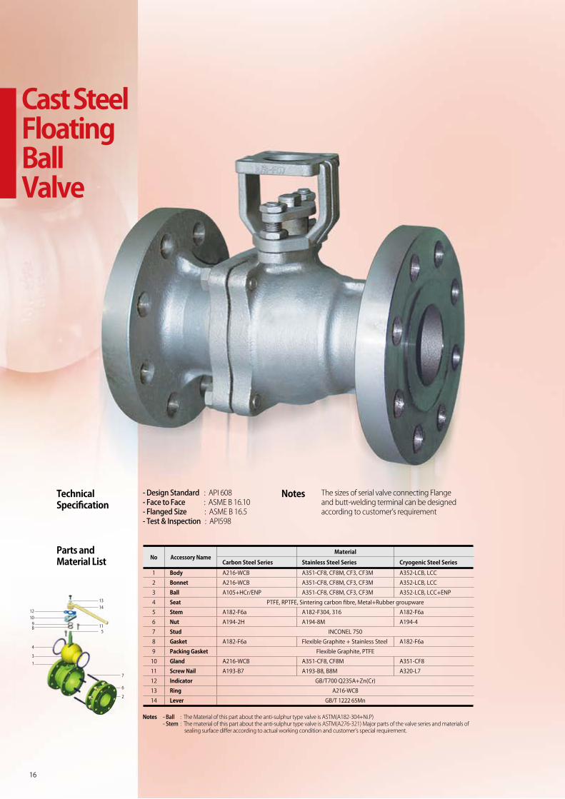
Cast Steel Floating Ball Valve
Notes
Technical Specification
Notes
Parts and Material List
16
- Design Standard : API 608- Face to Face : ASME B 16.10- Flanged Size : ASME B 16.5- Test & Inspection : API598
The sizes of serial valve connecting Flange and butt-welding terminal can be designed according to customer’s requirement
No Accessory NameMaterial
Carbon Steel Series Stainless Steel Series Cryogenic Steel Series
1 Body A216-WCB A351-CF8, CF8M, CF3, CF3M A352-LCB, LCC
2 Bonnet A216-WCB A351-CF8, CF8M, CF3, CF3M A352-LCB, LCC
3 Ball A105+HCr/ENP A351-CF8, CF8M, CF3, CF3M A352-LCB, LCC+ENP
4 Seat PTFE, RPTFE, Sintering carbon fibre, Metal+Rubber groupware
5 Stem A182-F6a A182-F304, 316 A182-F6a
6 Nut A194-2H A194-8M A194-4
7 Stud INCONEL 750
8 Gasket A182-F6a Flexible Graphite + Stainless Steel A182-F6a
9 Packing Gasket Flexible Graphite, PTFE
10 Gland A216-WCB A351-CF8, CF8M A351-CF8
11 Screw Nail A193-B7 A193-B8, B8M A320-L7
12 Indicator GB/T700 Q235A+Zn(Cr)
13 Ring A216-WCB
14 Lever GB/T 1222 65Mn
- Ball : The Material of this part about the anti-sulphur type valve is ASTM(A182-304+Ni.P)- Stem : The material of this part about the anti-sulphur type valve is ASTM(A276-321) Major parts of the valve series and materials of sealing surface differ according to actual working condition and customer’s special requirement.
12
1314
115
7
6
2
1098
4
3
1
17
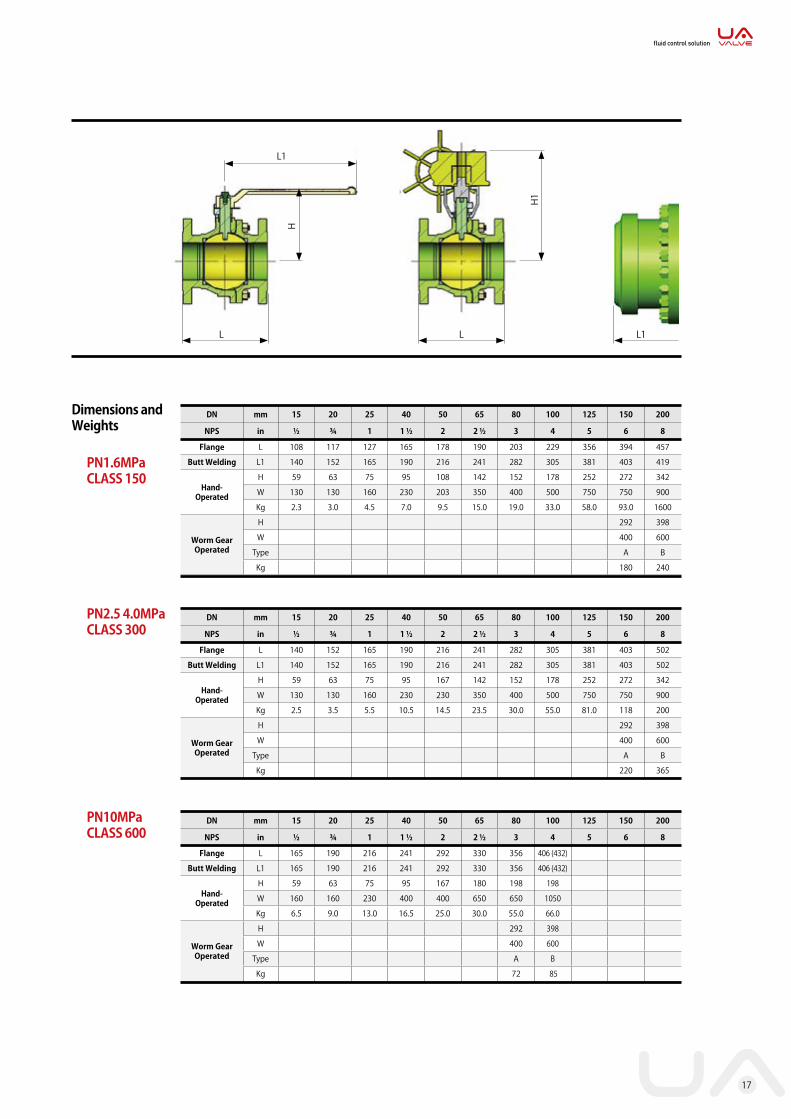
Dimensions and Weights
PN1.6MPa CLASS 150
DN mm 15 20 25 40 50 65 80 100 125 150 200
NPS in ½ ¾ 1 1 ½ 2 2 ½ 3 4 5 6 8
Flange L 108 117 127 165 178 190 203 229 356 394 457
Butt Welding L1 140 152 165 190 216 241 282 305 381 403 419
Hand-Operated
H 59 63 75 95 108 142 152 178 252 272 342
W 130 130 160 230 203 350 400 500 750 750 900
Kg 2.3 3.0 4.5 7.0 9.5 15.0 19.0 33.0 58.0 93.0 1600
Worm Gear Operated
H 292 398
W 400 600
Type A B
Kg 180 240
PN10MPa CLASS 600
DN mm 15 20 25 40 50 65 80 100 125 150 200
NPS in ½ ¾ 1 1 ½ 2 2 ½ 3 4 5 6 8
Flange L 165 190 216 241 292 330 356 406 (432)
Butt Welding L1 165 190 216 241 292 330 356 406 (432)
Hand-Operated
H 59 63 75 95 167 180 198 198
W 160 160 230 400 400 650 650 1050
Kg 6.5 9.0 13.0 16.5 25.0 30.0 55.0 66.0
Worm Gear Operated
H 292 398
W 400 600
Type A B
Kg 72 85
DN mm 15 20 25 40 50 65 80 100 125 150 200
NPS in ½ ¾ 1 1 ½ 2 2 ½ 3 4 5 6 8
Flange L 140 152 165 190 216 241 282 305 381 403 502
Butt Welding L1 140 152 165 190 216 241 282 305 381 403 502
Hand-Operated
H 59 63 75 95 167 142 152 178 252 272 342
W 130 130 160 230 230 350 400 500 750 750 900
Kg 2.5 3.5 5.5 10.5 14.5 23.5 30.0 55.0 81.0 118 200
Worm Gear Operated
H 292 398
W 400 600
Type A B
Kg 220 365
PN2.5 4.0MPa CLASS 300
L1
L
H
H1
L L1
fluid control solution
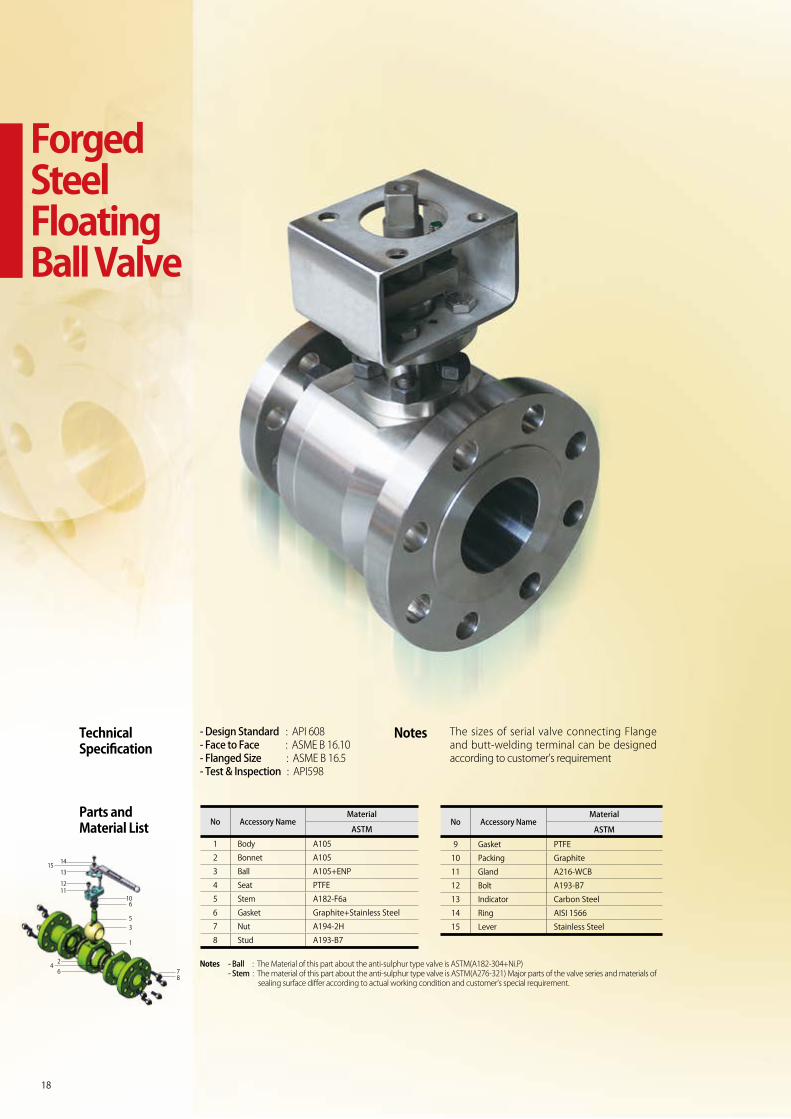
Forged Steel Floating Ball Valve
18
No Accessory NameMaterial
ASTM
1 Body A105
2 Bonnet A105
3 Ball A105+ENP
4 Seat PTFE
5 Stem A182-F6a
6 Gasket Graphite+Stainless Steel
7 Nut A194-2H
8 Stud A193-B7
No Accessory NameMaterial
ASTM
9 Gasket PTFE
10 Packing Graphite
11 Gland A216-WCB
12 Bolt A193-B7
13 Indicator Carbon Steel
14 Ring AISI 1566
15 Lever Stainless Steel
Technical Specification
Notes
Parts and Material List
Notes - Ball : The Material of this part about the anti-sulphur type valve is ASTM(A182-304+Ni.P)- Stem : The material of this part about the anti-sulphur type valve is ASTM(A276-321) Major parts of the valve series and materials of sealing surface differ according to actual working condition and customer’s special requirement.
- Design Standard : API 608- Face to Face : ASME B 16.10- Flanged Size : ASME B 16.5- Test & Inspection : API598
The sizes of serial valve connecting Flange and butt-welding terminal can be designed according to customer’s requirement
14
24
6
15
106
53
1
78
13
1211
19
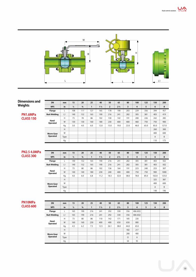
Dimensions and Weights
PN1.6MPa CLASS 150
DN mm 15 20 25 40 50 65 80 100 125 150 200
NPS in ½ ¾ 1 1 ½ 2 2 ½ 3 4 5 6 8
Flange L 108 117 127 165 178 190 203 229 356 394 457
Butt Welding L1 140 152 165 190 216 241 282 305 381 403 419
Hand-Operated
H 73 78 86 102 130 142 191 200 226 242 285
W 130 130 160 180 230 400 400 460 750 750 900
Kg 3.0 4.0 6.0 12.0 15.0 19.0 22.0 46.0 65.0 85.0 127.0
Worm Gear Operated
H 260 300
W 400 600
Type A B
Kg 110 175
PN10MPa CLASS 600
DN mm 15 20 25 40 50 65 80 100 125 150 200
NPS in ½ ¾ 1 1 ½ 2 2 ½ 3 4 5 6 8
Flange L 165 190 216 241 292 330 356 406 (432)
Butt Welding L1 165 190 216 241 292 330 356 406 (432)
Hand-Operated
H 73 80 86 110 142 171 185 220
W 160 160 230 400 400 650 650 800
Kg 4.5 6.2 7.5 12.5 26.1 38.0 44.0 65.0
Worm Gear Operated
H 182 217
W 280 400
Type O A
Kg 50 95
DN mm 15 20 25 40 50 65 80 100 125 150 200
NPS in ½ ¾ 1 1 ½ 2 2 ½ 3 4 5 6 8
Flange L 140 152 165 190 216 241 282 305 381 403 502
Butt Welding L1 140 152 165 190 216 241 282 305 381 403 502
Hand-Operated
H 73 80 86 102 136 164 191 223 240 253 307
W 140 140 180 230 240 400 400 750 750 900 1000
Kg 4.0 6.0 6.8 11.2 18.3 32.0 38.0 78.0 85.0 102.0 125.0
Worm Gear Operated
H 325 387
W 400 600
Type A B
Kg 148 196
PN2.5 4.0MPa CLASS 300
H
L L1
W
L
M
fluid control solution
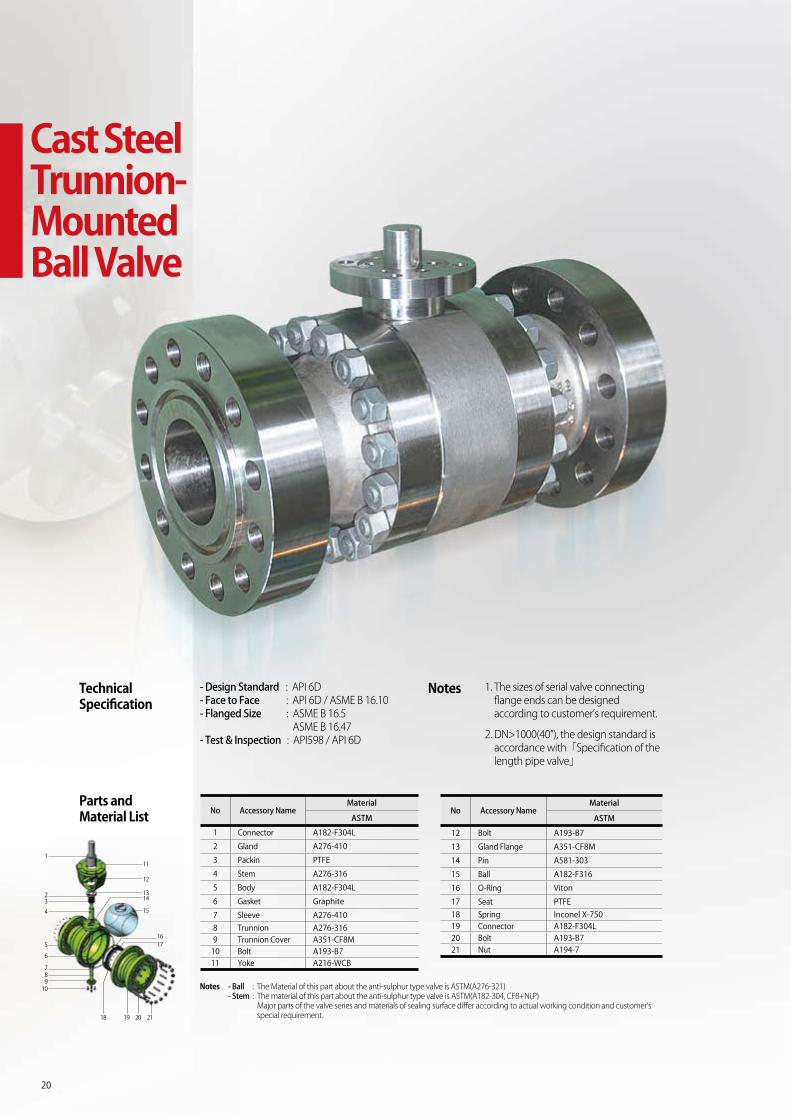
Cast Steel Trunnion-Mounted Ball Valve
20
Technical Specification
Notes- Design Standard : API 6D- Face to Face : API 6D / ASME B 16.10- Flanged Size : ASME B 16.5 ASME B 16.47- Test & Inspection : API598 / API 6D
1. The sizes of serial valve connecting flange ends can be designed according to customer’s requirement.
2. DN>1000(40”), the design standard is accordance with「Specification of the length pipe valve」
No Accessory NameMaterial
ASTM
1 Connector A182-F304L
2 Gland A276-410
3 Packin PTFE
4 Stem A276-316
5 Body A182-F304L
6 Gasket Graphite
7 Sleeve A276-4108 Trunnion A276-3169 Trunnion Cover A351-CF8M
10 Bolt A193-B711 Yoke A216-WCB
No Accessory NameMaterial
ASTM
12 Bolt A193-B7
13 Gland Flange A351-CF8M
14 Pin A581-303
15 Ball A182-F316
16 O-Ring Viton
17 Seat PTFE18 Spring Inconel X-75019 Connector A182-F304L20 Bolt A193-B721 Nut A194-7
Parts and Material List
Notes - Ball : The Material of this part about the anti-sulphur type valve is ASTM(A276-321)- Stem : The material of this part about the anti-sulphur type valve is ASTM(A182-304, CF8+Ni,P) Major parts of the valve series and materials of sealing surface differ according to actual working condition and customer’s special requirement.
111
13
12
14
15
1617
18 19 20 21
23
4
5
6
789
10
21
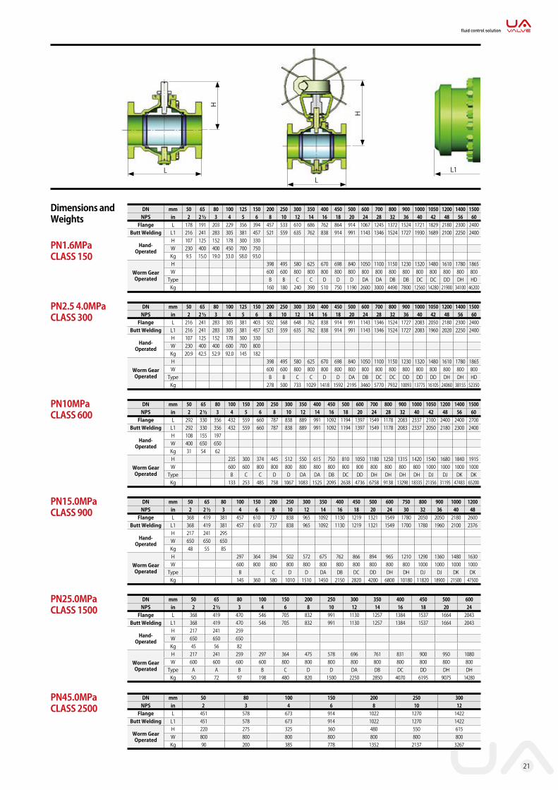
Dimensions and Weights
PN1.6MPa CLASS 150
DN mm 50 65 80 100 125 150 200 250 300 350 400 450 500 600 700 800 900 1000 1050 1200 1400 1500NPS in 2 2 ½ 3 4 5 6 8 10 12 14 16 18 20 24 28 32 36 40 42 48 56 60
Flange L 178 191 203 229 356 394 457 533 610 686 762 864 914 1067 1245 1372 1524 1721 1829 2180 2300 2400Butt Welding L1 216 241 283 305 381 457 521 559 635 762 838 914 991 1143 1346 1524 1727 1930 1689 2100 2250 2400
Hand-Operated
H 107 125 152 178 300 330W 230 400 400 450 700 750Kg 9.5 15.0 19.0 33.0 58.0 93.0
Worm Gear Operated
H 398 495 580 625 670 698 840 1050 1100 1150 1230 1320 1480 1610 1780 1865W 600 600 800 800 800 800 800 800 800 800 800 800 800 800 800 800
Type B B C C D D D DA DA DB DB DC DC DD DH HDKg 160 180 240 390 510 750 1190 2600 3000 4490 7800 12560 14280 21900 34100 46200
DN mm 50 65 80 100 125 150 200 250 300 350 400 450 500 600 700 800 900 1000 1050 1200 1400 1500NPS in 2 2 ½ 3 4 5 6 8 10 12 14 16 18 20 24 28 32 36 40 42 48 56 60
Flange L 216 241 283 305 381 403 502 568 648 762 838 914 991 1143 1346 1524 1727 2083 2050 2180 2300 2400Butt Welding L1 216 241 283 305 381 457 521 559 635 762 838 914 991 1143 1346 1524 1727 2083 1960 2020 2250 2400
Hand-Operated
H 107 125 152 178 300 330W 230 400 400 600 700 800Kg 20.9 42.5 52.9 92.0 145 182
Worm Gear Operated
H 398 495 580 625 670 698 840 1050 1100 1150 1230 1320 1480 1610 1780 1865W 600 600 800 800 800 800 800 800 800 800 800 800 800 800 800 800
Type B B C C D D DA DB DC DC DD DD DD DH DH HDKg 278 500 733 1029 1418 1592 2195 3460 5770 7932 10093 13775 16105 24060 38155 52350
DN mm 50 65 80 100 150 200 250 300 350 400 450 500 600 700 800 900 1000 1050 1200 1400 1500NPS in 2 2 ½ 3 4 5 6 8 10 12 14 16 18 20 24 28 32 40 42 48 56 60
Flange L 292 330 356 432 559 660 787 838 889 991 1092 1194 1397 1549 1178 2083 2337 2100 2400 2400 2700Butt Welding L1 292 330 356 432 559 660 787 838 889 991 1092 1194 1397 1549 1178 2083 2337 2050 2180 2300 2400
Hand-Operated
H 108 155 197W 400 650 650Kg 31 54 62
Worm Gear Operated
H 235 300 374 445 512 550 615 750 810 1050 1180 1250 1315 1420 1540 1680 1840 1915W 600 600 800 800 800 800 800 800 800 800 800 800 800 800 1000 1000 1000 1000
Type B C C D D DA DA DB DC DD DH DH DH DH DJ DJ DK DKKg 133 253 485 758 1067 1083 1525 2095 2638 4736 6758 9138 13298 18335 21356 31195 47483 65200
DN mm 50 65 80 100 150 200 250 300 350 400 450 500 600 750 800 900 1000 1200NPS in 2 2 ½ 3 4 6 8 10 12 14 16 18 20 24 30 32 36 40 48
Flange L 368 419 381 457 610 737 838 965 1092 1130 1219 1321 1549 1780 2050 2050 2180 2600Butt Welding L1 368 419 381 457 610 737 838 965 1092 1130 1219 1321 1549 1700 1780 1960 2100 2376
Hand-Operated
H 217 241 295W 650 650 650Kg 48 55 85
Worm Gear Operated
H 297 364 394 502 572 675 762 866 894 965 1210 1290 1360 1480 1630W 600 800 800 800 800 800 800 800 800 800 800 1000 1000 1000 1000
Type B C D D DA DB DC DD DH DH DJ DJ DK DKKg 145 360 580 1010 1510 1450 2150 2820 4200 6800 10180 11820 18900 21500 47500
DN mm 50 65 80 100 150 200 250 300 350 400 450 500 600NPS in 2 2 ½ 3 4 6 8 10 12 14 16 18 20 24
Flange L 368 419 470 546 705 832 991 1130 1257 1384 1537 1664 2043Butt Welding L1 368 419 470 546 705 832 991 1130 1257 1384 1537 1664 2043
Hand-Operated
H 217 241 259W 650 650 650Kg 45 56 82
Worm Gear Operated
H 217 241 259 297 364 475 578 696 761 831 900 950 1080W 600 600 600 600 800 800 800 800 800 800 800 800 800
Type A A B B C D D DA DB DC DD DH DHKg 50 72 97 198 480 820 1500 2250 2850 4070 6195 9075 14280
PN10MPa CLASS 600
PN15.0MPa CLASS 900
PN25.0MPa CLASS 1500
DN mm 50 80 100 150 200 250 300NPS in 2 3 4 6 8 10 12
Flange L 451 578 673 914 1022 1270 1422Butt Welding L1 451 578 673 914 1022 1270 1422
Worm Gear Operated
H 220 275 325 360 480 550 615W 800 800 800 800 800 800 800Kg 90 200 385 778 1352 2137 3267
PN45.0MPa CLASS 2500
PN2.5 4.0MPa CLASS 300
L1
H
LL
H
fluid control solution

Forged Steel Trunnion-Mounted Ball Valve
22
Notes - Ball : The Material of this part about the anti-sulphur type valve is ASTM(A182-304+Ni.P)- Stem : The material of this part about the anti-sulphur type valve is ASTM(A276-321) Major parts of the valve series and materials of sealing surface differ according to actual working condition and customer’s special requirement.
Technical Specification
Notes- Design Standard : API 6D- Face to Face : API 6D / ASME B 16.10- Flanged Size : ASME B 16.5 ASME B 16.47- Test & Inspection : API598 / API 6D
1. The sizes of serial valve connecting flange ends can be designed according to customer’s requirement.
2. DN>1000(40”), the design standard is accordance with「Specification of the length pipe valve」
No Accessory NameMaterial
ASTM
1 Mount Flange A182-F304
2 Gland A276-304
3 Gland Flange A276-304
4 Connector A182-F304L
5 Body A182-F304L
6 Spring Inconel X-750
7 Trunnion A276-3168 Gasket Graphite9 Trunnion Cover A276-316
No Accessory NameMaterial
ASTM
10 Stem A276-316
11 Packing Graphite
12 Gland Flange A276-304
13 Ball A276-316
14 Gasket Graphite
15 Seat A182-F304L + TC16 Bolt A193-B717 Nut A194-7
Parts and Material List
34
56789
14 15 16 17
2 1
1012
11
13

23
Dimensions and Weights
PN1.6MPa CLASS 150
PN10MPa CLASS 600
PN15.0MPa CLASS 900
PN25.0MPa CLASS 1500
PN2.5 4.0MPa CLASS 300
H
L L1L
H
No mm 50 65 80 100 125 150 200 250 300 350 400 450 500 600 700 800 900 1000 1050 1200 1400 1500NPS in 2 2 ½ 3 4 5 6 8 10 12 14 16 18 20 24 28 32 36 40 42 48 56 60
Flange L 178 191 283 329 356 394 457 553 610 686 762 864 914 1067 1245 1372 1524 1721 1829 2180 2300 2400Butt Welding L1 216 241 283 305 381 457 521 559 635 762 838 914 991 1143 1346 1524 1727 1930 1689 2100 2250 2400
Hand-Operated
H 130 142 191 200 226 242W 230 350 400 450 750 750Kg 12 28 33 50 78 93
Worm Gear Operated
H 337 385 414 447 545 545 585 663 723 923 986 1061 1420 1530 1640 1710W 600 600 800 800 800 800 800 800 800 800 800 800 800 800 800 800
Type B B C C D D D DA DA DB DB DC DC DD DH HDKg 250 390 578 770 1100 1250 1800 2400 4500 6900 9700 13000 15000 23000 37000 39500
No mm 50 65 80 100 125 150 200 250 300 350 400 450 500 600 700 800 900 1000 1050 1200 1400 1500NPS in 2 2 ½ 3 4 5 6 8 10 12 14 16 18 20 24 28 32 36 40 42 48 56 60
Flange L 216 241 283 305 381 403 502 568 648 762 838 914 991 1143 1346 1524 1727 2083 2050 2180 2300 2400Butt Welding L1 216 241 283 305 381 457 521 559 635 762 838 914 991 1143 1346 1524 1727 2083 1960 2020 2250 2400
Hand-Operated
H 136 164 191 223 240 253W 240 400 400 600 750 800Kg 32 37 58 110 157 180
Worm Gear Operated
H 337 385 414 447 545 545 585 663 723 923 986 1061 1420 1530 1640 1710W 600 600 800 800 800 800 800 800 800 800 800 800 800 800 800 800
Type B B C C D D DA DB DC DC DD DD DD DH DH HDKg 280 410 760 1100 1600 1700 2300 3500 6000 8000 11000 14000 17000 25000 39500 45300
No mm 50 65 80 100 150 200 250 300 350 400 450 500 600 700 800 900 1000 1050 1200 1400 1500NPS in 2 2 ½ 3 4 5 6 8 10 12 14 16 18 20 24 28 32 40 42 48 56 60
Flange L 292 330 356 432 559 660 787 838 889 991 1092 1194 1397 1549 1178 2083 2337 2100 2400 2400 2700Butt Welding L1 292 330 356 432 559 660 787 838 889 991 1092 1194 1397 1549 1178 2083 2337 2050 2180 2300 2400
Hand-Operated
H 136 164 191W 500 650 650Kg 35 42 66
Worm Gear Operated
H 244 309 361 412 475 502 533 636 675 759 836 915 987 1212 1460 1600 1760 1845W 600 600 800 800 800 800 800 800 800 800 800 800 800 800 1000 1000 1000 1000
Type B C C D D DA DA DB DC DD DH DH DH DH DJ DJ DK DKKg 180 270 500 780 1100 1200 1600 2160 2700 5000 7000 9800 14000 19000 22000 32000 49000 56000
No mm 50 65 80 100 150 200 250 300 350 400 450 500 600 750 800 900 1000 1200NPS in 2 2 ½ 3 4 6 8 10 12 14 16 18 20 24 30 32 36 40 48
Flange L 368 419 381 457 610 737 838 965 1092 1130 1219 1321 1549 1780 2050 2050 2180 2600Butt Welding L1 368 419 381 457 610 737 838 965 1092 1130 1219 1321 1549 1700 1780 1960 2100 2376
Hand-Operated
H 148 191 216W 650 650 650Kg 50 55 80
Worm Gear Operated
H 270 384 435 518 657 693 762 866 894 965 1160 1240 1310 1450 1530W 600 800 800 800 800 800 800 800 800 800 800 1000 1000 1000 1000
Type B C D D DA DB DC DD DH DH DJ DJ DK DKKg 150 360 620 1100 1600 1850 2200 2800 4250 7000 12500 14500 18000 22000 32000
No mm 50 65 80 100 150 200 250 300 350 400 450 500 600NPS in 2 2 ½ 3 4 6 8 10 12 14 16 18 20 24
Flange L 368 419 470 546 705 832 991 1130 1257 1384 1537 1664 2043Butt Welding L1 368 419 470 546 705 832 991 1130 1257 1384 1537 1664 2043
Hand-Operated
H 175 191 216W 650 650 750Kg 60 70 85
Worm Gear Operated
H 175 91 216 247 329 492 428 640 670 700 755 830 952W 400 400 600 600 800 800 800 800 800 800 800 800 800
Type A A B B C D D DA DB DC DD DH DHKg 65 82 100 210 500 850 1600 2300 2950 4200 5000 5600 2200
fluid control solution
DN mm 50 80 100 150 200 250 300NPS in 2 3 4 6 8 10 12
Flange L 451 578 673 914 1022 1270 1422Butt Welding L1 451 578 673 914 1022 1270 1422
Worm Gear Operated
H 220 275 325 360 480 550 615W 800 800 800 800 800 800 800Kg 90 200 385 778 1352 2137 3267
PN45.0MPa CLASS 2500
1506-3 Seosam-Ro Chukdong-Myen Sacheon-Si Gyungsangnam-Do, Koreawww.uavalve.co.kr
Tel. 82-55-852-5456~7 Fax. 82-55-852-9911
Copyright ⓒ 2013. 07. UA VALVE All Rights Reserved. / Designed by TABS communication Co.,Ltd.
Product System
• Chemical Plants• Fats, Oils, Fatty Acid and Detergent Plants• Power Plants-Fossil Fuel• Breweries & Distilleries• Electrical Component Plants• Foundries• Power Plant-Nuclear• Coke By-Products Plants• Food Processing Plants• Paint & Paint Product Plants• Textile Industry• Steel & Other Metal Processing Plants• Rubber & Synthetic Rubber Products Plants• Petroleum Products & Handling Systems• Pulp & Paper Plants• Pharmaceutical Plants• Water Treatment-Purification
※ The product is subject to change for technical development and quality improvement without prior notice.


