25
UNIVERSITI PUTRA MALAYSIA DEVELOPMENT OF AN ELECTRIC VEHICLE DASHBOARD MONITORING SYSTEM USING MICROCONTROLLER MOHAMMED E. SALEM ABOZAED FK 2000 12
UNIVERSITI PUTRA MALAYSIA
DEVELOPMENT OF AN ELECTRIC VEHICLE DASHBOARD MONITORING SYSTEM USING MICROCONTROLLER
MOHAMMED E. SALEM ABOZAED
FK 2000 12
DEVELOPMENT OF AN ELECTRIC VEHICLE DASHBOARD MONITORING SYSTEM USING MICROCONTROLLER
By
MOHAMMED E. SALEM ABOZAED
Thesis Submitted in Partial Fulfilment of the Requirements for the Degree of Master of Science in the Faculty of Engineering
Universiti Putra Malaysia
January 2000

I Dedicate This Work to
My Parents and My Wife
2

Abstract of thesis presented to the Senate ofUniversiti Putra Malaysia in partial fulfilment of the requirements for the degree of Master of Science.
DEVELOPMENT OF AN ELECTRIC VEHICLE DASHBOARD MONITORING SYSTEM USING MICROCONTROLLER
By
MOHAMMED E. SALEM ABOZAED
Chairman: Ishak Aris, Ph.D
Faculty: Engineering
January 2000
A microcontroller is a complete microcomputer on a chip that integrates a
CPU with memory and various peripherals such as anal og-to-di gital converters
(AID), serial communication units etc. Microcontrollers are designed to be
embedded within event-driven control applications and generally have all necessary
peripherals integrated onto the same piece of silicon. An Intelligent Energy
Management System (IEMS) is a microcontroller based system which is used in an
electric vehicle to monitor and control the various parts of the vehicle such as the
motor and motor drives, the current and voltage of the battery packs, dashboard,
pedals and other subsystems. This aids the driver to achieve optimal driving
conditions from the vehicle.
In tropical countries the temperature is very high especially during the day.
As a result, when the vehicles are parked in an open space the temperature in the
vehicle rises and this could lead to many problems. The objective of this project
was to develop an Automatic Fan Controlling System (AFCS), which may be used to
control the temperature of the electrical vehicle cabin to counter any potential
3
problems. This new proposed system is one of the many systems that may be made
available to the user via the IEMS. This proj ect also looked into the development of
the battery pack voltage level monitoring system for electric vehicles.
The MC68HC 11 evaluation board (EVB) NMIX-0020, which uses a
Motorola F68HC l l microcontroller for its CPU, is used to monitor and control both
of the systems mentioned above. The development work carried out for the
automatic fan controlling system and the battery pack voltage level monitoring
system include the design, construct and testing of the system.
The automatic fan controlling system consists of a temperature sensor
(AD590), a current-to-voltage converter, digital relay and a microcontroller. The
battery pack voltage level monitoring system comprises of a voltage divider, a digital
display and a microcontroller.
Simulation and experimental results are also included and discussed in detail.
Based on these results, the systems mentioned above have been successfully
developed. The systems can be extended for high temperature controlling and high
voltage monitoring by changing some parameters in both systems.
4
Abstrak tesis yang dikemukakan kepada Senat Universiti Putra Malaysia sebagai memenuhi sebahagian dari keperluan untuk ijazah Master Sains.
PEMBANGUNAN SEBUAB SISTEM PENGA WASAN PANEL KA W AL KENDERAAN ELEKTRIK MENGGUNAKAN PENGA WAL-MIKRO
Oleh
MOHAMMED E. SALEM ABOZAED
Pengerusi: Ishak Aris, Ph.D
Faculti: Kejuruteraan
Januari 2000
Pengawal-mikro adalah komputer-mikro lengkap di dalam sebuah chip di
mana unit pemprosesan pusat (CPU) beserta dengan ingatan digabungkan dengan
berbagai peralatan seperti pengubah analog-kepada-digital, unit komunikasi siri dan
lain-lain. Pengawal-mikro direka untuk dimuatkan ke dalam aplikasi pemacu-
keadaan terkawal (event-driven), dan selalunya mempungai alat-alat yang di
integrasikan bersama di dalam unit silikon yang sarna. Sistem pengurusan tenaga
pintar [Intelligent Energy Management System (IEMS)] adalah sistem berasaskan
pengawal-mikro yang digunakan di dalam kenderaan elektrik bagi mengawasi dan
mengawal berbagai bahagian kenderaan seperti motor dan pemacu motor, arus dan
voltan untuk pak bateri, papan kawai, pengayuh dan juga lain-lain sub-sistem. Sistem
ini akan dapat membantu pengendalian kenderaan dalam keadaan yang optimum.
Bagi negara tropikal, cuaca biasanya adalah panas terutamanya pada waktu
siang. Jika kenderaan diletakkan ditempat lapang, suhu di dalam kenderaan akan naik
pada tahap yang tinggi. Ini boleh membawa kepada berbagai masalah. Objektif
projek ini adalah untuk membina sistem pengawalan kipas otomatik [Automatic Fan
5
Controlling System (AFCS)] yang boleh digunakan untuk mengawal suhu ruang
kenderaan elektrik bagi mengelakkan masalah yang disebabkan oleh suhu yang
tinggi. Sistem barn yang dicadangkan ini adalah di antara sistem yang boleh
dibekalkan kepada pengguna-pengguna melalui teknologi IEMS. Projek ini juga
akan melibatkan pembangunan satu sistem pengawasan tahap voltan pak bateri bagi
kenderaan elektrik.
Papan penilaian MC68HC 11 NMIX-0020 (EVB) yang menggunakan
pengawal-mikro Motorola F68HCll sebagai unit pemprosesan pusat (central
processing unit) digunakan untuk mengawasi dan mengawal kedua-dua sistem yang
dicadangkan di atas. Kerja-kerja pembangunan yang telah dijalankan termasuklah
rekabentuk, pembinaan dan ujian ke atas sistem-sistem tersebut.
Sistem pengawalan kipas otomatik terdiri dari pengesan suhu (AD590),
penukar arus kepada voltan, penyampai digital dan pengawal mikro. Sistem
pengawasan tahap voltan pak bateri terdiri dari pembahagi voltan, layar digital dan
pengawal mikro.
Hasil-hasil keputusan simulasi dan ujikaji juga disertakan dan dibincangkan
secara mendalam. Berdasarkan dari keputusan tersebut, sistem-sistem yang
disebutkan di atas telah berjaya dibangunkan. Sistem ini boleh diubahsuai dan
digunakan untuk mengawal suhu tinggi dan memantau voltan tinggi dengan
mengubah parameter yang berkaitan dengan kedua-dua sistem tersebut.
6

ACKNOWLEDGEMENTS
First of all, I would like to thank my Lord Allah the most gracious and merciful,
who gave me the ability to carry out this project. Selawat and Salaam to his Righteous
Messenger, Prophet Muhammad S.A.W.
I wish to express my profound appreciation and gratitude to the Chairman of the
Supervisory Committee, Dr. Ishak bin Aris, for his supervision, guidance and
constructive suggestions and comments throughout the duration of this project.
I am also grateful to the members of the Supervisory Committee, Dr. Norman
Mariun and Dr. Samsul Bahari Mohd. Noor, for their kind guidance, prompt decisions
and valuable assistance throughout this project.
Great appreciation is also due to Mr. Yasin M. and the other technicians of
Electrical and Electronics Engineering Department for their technical support. I wish also
to thank the Faculty of Engineering for providing the facilities and the components
required for undertaking this project.
Last but not least, I would like to thank my friends, especially En. Azzadden
Mohammed Salah, for their encouragement and support.
7

I certify that Examination Committee met on 24 January, 2000 to conduct the final examination of Mohammed E. Salem Abozaed on his Master of Science thesis entitled "Development of an Electric Vehicle Dashboard Monitoring System Using Microcontroller" in accordance with Universiti Pertanian Malaysia (Higher Degree) Act 1980 and Universiti Pertanian Malaysia (Higher Degree) Regulation 1981. The Committee recommends that the candidate be awarded the relevant degree. Members of the Examination Committee are as follows:
Nasrullah Khan, PhD. Faculty of Engineering Universiti Putra Malaysia (Chairman)
Ishak Aris, PhD. Faculty of Engineering Universiti Putra Malaysia (Member)
Norman Mariun, PhD. Faculty of Engineering Universiti Putra Malaysia (Member)
S. B. M. Noor, PhD. Faculty of Engineering Universiti Putra Malaysia (Member)
. GHAZALI MOHA YIDIN, Ph.D. ProfessorlDeputy Dean of Graduate School
Date: - 2 FEB 2000 -
8

This thesis was submitted to the Senate of Universiti Putra Malaysia and was accepted as Partial Fulfillment of the requirements for the degree of Master of Science.
KAMIS A WANG, Ph.D. Associate ProfessorlDean of Graduate school Universiti Putra Malaysia
1 a FEB 2000
9
DECLARA nON
I hereby declare that the thesis is based on my original work except for the quotations and citations, which have been duly acknowledged. I also declare that it has not previously or concurrently submitted for any other degree at UPM or other institutions.
Signed
(� Candidate. Name: Mohammed E. Salem Abozaed Date: 2/2/2000
1 0

TABLE OF CONTENTS
Page
DEDICATION . . . . . . . . . . . . . . . . . . . . . . . . . . . . . . . . . . . . . . . . . . . . . . . . . . . . . . . . . . . . . . . . . . . . . . . 2 ABSTRACT . . . . . . . . . . . . . . . . . . . . . . . . . . . . . . . . . . . . . . . . . . . . . . . . . . . . . . . . . . . . . . . . . . . . . . . . . . 3 ABSTRAK . . . . . . . . . . . . . . . . . . . . . . . . . . . . . . . . . . . . . . . . . . . . . . . . . . . . . . . . . . . . . . . . . . . . . . . . . . . 5 ACKNOWLEDGEMENTS . . . . . . . . . . . . . . . . . . . . . . , . . . . . . . . . . . . . . . . . . . . . . . . . . . . . . . . 7 APPROVAL SHEETS . . . . . . . . . . . . . . . . . . . . . . . . . . . . . . . . . . . . . . . . . . . . . . . . . . . . . . . . . . . . . 8 DECLERATION FORM . . . . . . . . . . . . . . . . . . . . . . . . . . . . . . . . . . . . . . . . . . . . . . . . . . . . . . . . . . 10 LIST OF TABLES . . . . . . . . . . . . . . . . . . . . . . . . . . . . . . . . . . . . . . . . . . . . . . . . . . . . . . . . . . . . . . . . . . 1 4 LIST OF FIGURES . . . . . . . . . . . . . . . . . . . . . . . . . . . . . . . . . . . . . . . . . . . . . . . . . . . . . . . . . . . . . . . . 1 5 LIST OF PLATES . . . . . . . . . . . . . . . . . . . . . . . . . . . . . . . . . . . . . . . . . . . . . . . . . . . . . . . . . . . . . . . . . . 17 LIST OF SYMBOLS AND ABBREVIATIONS . . . . . . . . . . . . . . . . . . . . . . . . . . . . . . 1 8
CHAPTER
I
II
INTRODUCTION Temperature Control in Passenger Cabins . . . . . . . . . . . . . . . . . . . . . . . . .
Battery Pack Voltage Level Monitoring System . . . . . . . . . . . . . . . . .
Objective ofthe Project . . . . . . . . . . . . . . . . . . . . . . . . . . . . . . . . . . . . . . . . . . . . . .
Layout of the Thesis . . . . . . . . . . . . . . . . . . . . . . . . . . . . . . . . . . . . . . . . . . . . . . . . .
LITERATURE REVIEW History of Electric Vehicles . . . . . . . . . . . . . . . . . . . . . . . . . . . . . . . . . . . . . . . . .
The Electric Vehicle Controller . . . . . . . . . . . . . . . . . . . . . . . . . . . . . . . . . . . . . . .
Electric Vehicle Power Systems (Motors and Controllers) . . .
Motors . . . . . . . . . . . . . . . . . . . . . . . . . . . . . . . . . . . . . . . . . . . . . . . . . . . . . . . . . . .
Controllers What is a Microcontroller? . . . . . . . . . . . . . . . . . . . . . . . . . . . . . . . . . . . . . . . . . .
Historical Background of Micro controllers . . . . . . . . . . . . . . . . . . . . . .
Central Processing Unit . . . . . . . . . . . . . . . . . . . . . . . . . . . . . . . . . . . . . . . . . . . . .
The Difference Between Microcontrollers and Microprocessors. The Advantages of Using the 68HCl1 Microcontroller For Controlling . . . . . . . . . . . . . . . . . . . . . . . . . . . . . . . . . . . . . . . . . . . . . . . . . . . . . . . . . . . .
Intelligent Energy Management (Microcontroller) . . . . . . . . . . . . . .
Temperature control using Microcontroller . . . . . . . . . . . . . . . . . . . . . .
Temperature Control of Hot-Tub Using the F68HC 1 1 . . . . . . . . . . .
Batteries in Electric Vehicles . . . . . . . . . . . . . . . . . . . . . . . . . . . . . . . . . . . . . .
Types of Batteries . . . . . . . . . . . . . . . . . . . . . . . . . . . . . . . . . . . . . . . . . . . . . . . . . . . . .
Electric Vehicle Battery Chargers . . . . . . . . . . . . . . . . . . . . . . . . . . . . . . . . . .
Battery Voltage Level Monitoring system . . . . . . . . . . . . . . . . . . . . . . .
Summary . . . . . . . . . . . . . . . . . . . . . . . . . . . . . . . . . . . . . . . . . . . . . . . . . . . . . . . . . . . . .
1 1
20 21 21 22 23
24 24 25 26 27 28 3 1 33 34 35
36 36 37 38 39 40 41 42 42
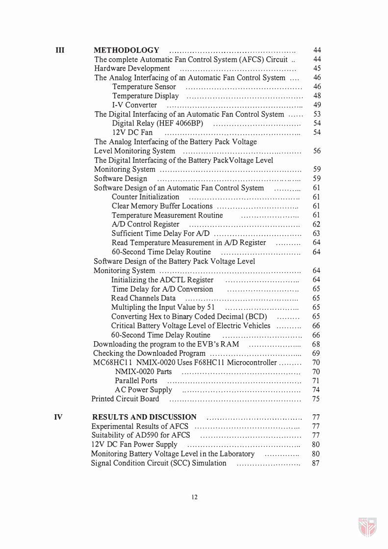
III
IV
METHODOLOGY The complete Automatic Fan Control System (AFCS) Circuit . . Hardware Development .. ... .. .... ....... ..... .. . ............. .... . .
The Analog Interfacing of an Automatic Fan Control System ... . Temperature Sensor ........... ... . ... . ....................... .. .
Temperature Display .. . .. .. . .. . . . . . .. . . ... . . . . . . . . . . . . . . .. . .. . . . . I-V Converter . ... . . . . .. .. . . . ... . . . . . . . ............ . . . . . . . . . . . .. . . .
The Digital Interfacing of an Automatic Fan Control System . . ... .
Digital Relay (HEF 4066BP) . . .. . . . . . . ... . .. .... . . .. . .. . . . . . . .
1 2V DC Fan ............. .......... . .... .......... .. ......... .. . .
The Analog Interfacing of the Battery Pack Voltage
44 44 45 46 46 48 49 53 54 54
Level Monitoring System .. . .... . . ..... .. ... . . . . . . .. ... . . . . . . . . . .. ..... 56 The Digital Interfacing of the Battery PackVoltage Level Monitoring System . . . . . . . . . . . . . . . . . . . . . . . . . . . . . . . . . . . . . . . . . . . . . . . . . . . . . . . 59 Software Design . . .. . .... ........ .. . . .. . . . .. . .. . .. . .. . .. . . . . . . . . . . . . . . . . 59 Software Design of an Automatic Fan Control System .. . . . .... .. 6 1
Counter Initialization . . . . . . . . . . . . . . . . . . . . . . . . . . . . . . . . . . . . . . . . . . . 6 1 Clear Memory Buffer Locations .... . .. . . .. . . ................. .. 6 1 Temperature Measurement Routine . . .. .. .... ... . . . .. . .. . . 6 1 NO Control Register . . . . . . . . . . . . . . . . . . . . . . . . . . . . . . . . . . . . . . . . . . . 62 Sufficient Time Delay For NO .. . . . . . . . . . . . . . . . . . . . . . . . . . . . . . . . . 63 Read Temperature Measurement in NO Register . ... . . . .. . 64 60-Second Time Delay Routine . . . . . . . . . . . . . . . . . . . . . . . . . . . . . . . 64
Software Design of the Battery Pack Voltage Level Monitoring System .. .. .... . . . .. . . . . . . . . . . . . . . . . . . . . . . . . . . . . . .. . . . .. .. . . . . 64
Initializing the ADCTL Register . . . . . . . . . . . . . . . . . . . . . . . . . . .. . 64 Time Delay for ND Conversion . . . . . . . . . . . . . . . . . . . . . . . . . . .. 65 Read Channels Data . . . . . . . . . . . . . . . . . . . . . . . . . . . . . . . . . . . . . . . . . ... 65 Multipling the Input Value by 5 1 . . .. .. .. . . .. .. . . .. . . . . . . .. .. . 65 Converting Hex to Binary Coded Decimal (BCD) . . .. ..... 65 Critical Battery Voltage Level of Electric Vehicles . . . . . . . . . . 66 60-Second Time Delay Routine . . . . . . . . . . . . . . . . . . . . . . . . . . . . . . . 66
Downloading the program to the EVB' s RAM . . . . . . . . . . . . . . . . . . . . . 68 Checking the Downloaded Program . . . . .. .... .... ..... .. .. .. . . ..... .... 69 MC68HCll NMIX-0020 Uses F68HC l l Microcontroller. . ... .... 70
NMIX-0020 Parts .. .. ...... ... . ... . . . . . . .. . . . . ..... ... ... .... . . 70 Parallel Ports . . .. . . .. . . ... . .. . ....... . . . . . . . . .. . . . . . . . .. . ... ... .. 7 1 AC Power Supply . . ..... . .. ... .. .... . .............. . .. .. . . . . . . . 74
Printed Circuit Board . . . . . . . . . . . . . . . . . . . . . . . . . . . . . . . . . . . . . . . . . . . . . . . . . . . 75
RESUL TS AND DISCUSSION Experimental Results of AFCS . . . . . . . .. . . ... . . . . . . . . . . . . . . . . . .. . . .. . . . .
Suitability of AD590 for AFCS . .. . . ...... ... ... ......... .. . . . ... .... .
1 2V DC Fan Power Supply . .. . .. .... . . . .. ... . .. . . . .. .. .. ...... . .. . . . . .
Monitoring Battery Voltage Level in the Laboratory ............. . Signal Condition Circuit (SCC) Simulation ............... ......... .
1 2
77 77 77 80 80 87

The Simulation of Voltage Dividers For Battery Voltage Monitoring 90 The Common Problems of Operating Microcontroller Encountered in this Project and Solutions . . . . . . . . . . . . . . . . . . . . . . . . . . . . . . . . . . . . . . . . . . . 9 1
V CONCLUSIONS AND FURTHER RECOMMENDED STUDIES 93
REFERENCES . . . . . . . . . . . . . . . . . . . . . . . . . . . . . . . . . . . . . . . . . . . . . . . . . . . . . . . . . . . . . . . . . . . . . . . . 95
APPENDIX
A Controlling Program for Monitoring Battery and Temperature
97
Controlling . . . . . . . . . . . . . . . . . . . . . . . . . . . . . . . . . . . . . . . . . . . . . . . . . . . . . . . . . . . . . . . . 99
B Temperature Sensor (AD590) Data Sheet . . . . . . . . . . . . . . . . . . . . . . . . . . . 1 04
C I-V Converter (OP07) Data Sheet . . . . . . . . . . . . . . . . . . . . . . . . . . . . . . . . . . . . . . . 1 1 5
D
E
F
VITA
Digital Relay (HEF4066BP) Data Sheet . . . . . . . . . . . . . . . . . . . . . . . . . . . . .
AID Converter (ICL7 1 07) Data Sheet . . . . . . . . . . . . . . . . . . . . . . . . . . . . . . .
Microcontroller Data Sheet . . . . . . . . . . . . . . . . . . . . . . . . . . . .. . . . . . . . . . . . . . . . .
13
1 20
129
1 46
1 49

LIST OF TABLES
Table Page
1 The input battery voltage value, the voltage divider output of input voltage, the hex value of voltage divider and the battery voltage display . . . . . . . . . . 82
14
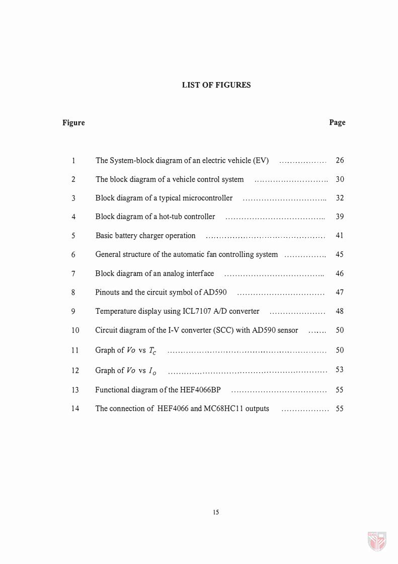
LIST OF FIGURES
Figure Page
1 The System-block diagram of an electric vehicle (EV) 26
2 The block diagram of a vehicle control system . . . . . . . . . . . . . . . . . . . . . . . . . . . . 3 0
3
4
5
6
7
8
9
1 0
1 1
Block diagram of a typical microcontroller . . . . . . . . . . . . . . . . . . . . . . . . . . . . . . . .
Block diagram of a hot-tub controller . . . . . . . . . . . . . . . . . . . . . . . . . . . . . . . . . . . . . .
Basic battery charger operation
General structure of the automatic fan controlling system . . . . . . . . . . . . . . . .
Block diagram of an analog interface . . . . . . . . . . . . . . . . . . . . . . . . . . . . . . . . . . . . . .
Pinouts and the circuit symbol of AD590 . . . . . . . . . . . . . . . . . . . . . . . . . . . . . . . . .
Temperature display using ICL7 1 07 AID converter . . . . . . . . . . . . . . . . . . . . .
Circuit diagram of the I-V converter (SCC) with AD590 sensor
Graph of Vo vs Tc
32
39
41
45
46
47
48
50
50
1 2 Graph of Vo vs 10 . . . . . . . . . . . . . . . . . . . . . . . . . . . . . . . . . . . . . . . . . . . . . . . . . . . . . . . . . . . . 53
13 Functional diagram of the HEF4066BP . . . . . . . . . . . . . . . . . . . . . . . . . . . . . . . . . . . . 55
1 4 The connection of HEF4066 and MC68HC 1 1 outputs . . . . . . . . . . . . . . . . . . 55
1 5

1 5
1 6
Block diagram o f the battery pack voltage level monitoring system . . . . . .
The voltage divider circuit
56
57
1 7 Complete circuit diagram o f the battery pack voltage
level monitoring system . . . . . . . . . . . . . . . . . . . . . . . . . . . . '" . . . . . . . . . . . . . . . . . . . . . . . . . . 59
1 8 Flowchart of the main program of the temperature controlling system
and the battery voltage level monitoring system 60
1 9 Flowchart of the microcontroller control program for APCS . . . . . . . . . . . . . . . . . 62
20 Flowchart of the microcontroller-monitoring program for
the battery pack voltage level monitoring system . . . . . . . . . . . . . . .. . . . . . .. . 67
2 1 Schematic PCB diagram of the control circuit for APCS . . . . . . . . . . . . . . . . . . . 76
22 The output DC voltage of the current-to-voltage converter at 260 c 78
23 The output DC voltage of the current-to-voltage converter at 28 a C 79
24 Capacitor filter operation . . . . . . . . . . . . . . . . . . . . . . . . . . . . . . . . . . . . . . . . . . . . . . . . . . . . 8 1
25 Graph of battery voltage input vs voltage divider . . . . . . . . . . . . . . . . . . . . . . . . . 83
26 Graph of battery voltage display vs voltage divider .. ... . ... . . . . . . .. . . . . . . 84
27 Graph comparing the battery voltage display to the battery voltage input 85
28 First simulation of the signal condition circuit (SCC) . . . . . . . . . . . . . . . . . . . .. 87
29 Second simulation of the signal condition circuit (SCC) . . . . . . . . . . .. . . . ... 88
30
3 1
Third simulation of the signal condition circuit (SCC)
Voltage divider simulation at battery voltage 1 30V
. . . . . . . . . . . . . . . . . . . . 89
. . . . . . . . . . . . . . . . . . . . . . . . 90
32 Voltage divider simulation at battery voltage 65V . .. . . . . . . . . . . . . . .. . . . . . . . . 9 1
1 6

LIST OF PLATES
Plate Page
1 Temperature display using lCL 7 1 07 AID converter . . . . . . . . . . . . . . . . . . . . . . . . 49
2 The complete circuit for the AFCS . . . . . . . . . . . . . . . . . . . . . . . . . . . . . . . . . . . . . . . . . . . . . . 56
3 Photograph of the battery pack voltage level monitoring system . . . . . . . . . . . . 58
4 NMlX-0020 evaluation board . . . . . . . . . . . . . . . . . . . . . . . . . . . . . . . . . . . . . . . . . . . . . . . . . . . . 71
5 The prototype of the APCS . . . . . . . . . . . . . . . . . . . . . . . . . . . . . . . . . . . . . . . . . . . . . . . . . . . . . . 86
6 The prototype of the AFCS and the battery voltage monitoring system . . . . . . 86
1 7
AFCS
ADCTL
AS 1 1
ADC
ABS
BUFFALO
CPU
DDR
EMS
EV
EVB
EROM
ECU
HCMOS
IEMS
10
ICEV
LCD
LED
MCU
LIST OF SYMBOLS AND ABBREVIATIONS
Automatic Fan Control System
Control-Status Register
Assembler Program
Analog-to-Digital Converter
Antilock Braking System
Bit User Fast Friendly Aid to Logical Operation
Central Processing Unit
Data Direction Registers.
Energy Management System
Electric Vehicle
Evaluation Board
Erasable Read-Only Memory
Electronic Control Unit
High-Density Complementary Metal-oxide Semiconductor
Intelligent Energy Management System
Output Current of the Temperature Transducer
Internal Combustion Engine Vehicle
Liquid Crystal Display
Light Emitting Diode
Microcontroller Unit
18
RAM Random-Access Memory
ROM Read-Only Memory
Rf Feedback Resistor
R Current Limiting Resistor
SI9 Assembling File
SCC Signal Conditioning Circuit
SCI Serial Communications Interface
SPI Serial Peripheral Interface
Vo Output Voltage of the Converter
VI DC Voltage
Vc Capacitor Voltage
Vm Peak Rectifier Voltage
19
CHAPTER I
INTRODUCTION
A microcontroller performs various functions in automobiles and it can be found in
the heart of almost any Electronic Control Unit (ECU) in use today. At least one
microcontroller within the ECU is used to control the antilock braking system (ABS),
engine performance, navigation, temperature, and vehicle dynamics. Understanding the
various features and offerings of microcontrollers that are available in the market today
is important when making a selection for an application (Derato, 1994).
The electric vehicle is one automobile, which uses microcontrollers to monitor and
control all its subsystems. Variables like temperature, speed, current, and voltage which
are basic to the vehicles operation are measured with transducers that convert operating
condition measurements to analog signals. These signals are then digitized and relayed
to the microcontroller. It evaluates the subsystem signals and accordingly sends out
control signals.
20
Temperature Control in Passenger Cabins
The microcontroller in electric vehicles is an intelligent system, which can monitor
various operations at a high speed obtaining optimum results, and can also perform
multifunction simultaneously. The controlling of temperature in passenger cabins is a
new area that can be added to the microcontroller's previous uses. This temperature
control will protect the windscreen from damage and prevent deformation of plastic
based instrumentation in the vehicle, in addition to prevent poor ventilation when the
vehicle is parked in open space during the day
Temperature control can also be used in Gasoline Vehicles, but its primary use
will be for electric vehicles, the vehicle of the next millenium. Most advanced electric
vehicles use microcontrollers and advantages include eliminating emissions from the car
thus protecting the environment, eradicating oil stains that run off and pollute
watersheds, removing the necessity of having tune-ups, no more requiring messy oil
changes, or need for coolants (Suggs, 1994).
Battery Pack Voltage Level Monitoring System
The battery is the heart of the electric vehicle and the monitoring of the battery
pack voltage level in the dashboard is the key to the operation of the vehicle. The driver
can monitor the status of the battery voltage level by observing the voltage indicator in
the dashboard and thus knows when it is time to charge the battery again.
2 1
Objective of the Project
Objective of this project is to design, construct and test the microcontroller-based
temperature control and battery pack voltage level monitoring systems in electric
vehicles.
Temperature control system is used as mentioned before to protect the windscreen
from damage and prevent deformation of plastic-based instrumentation used in the
vehicle, in addition to preventing poor ventilation when the vehicle is parked in open
space during the day. The monitoring of the battery pack voltage level in the dashboard
is essential to prevent the battery from being totally discharged.
The temperature controller and the battery voltage monitor consist of both hardware
and software. The hardware of the temperature controller includes analog interfacing
(temperature sensor and signal conditioning circuit) and digital interfacing. The
hardware of the battery voltage monitor includes the analog interfacing (voltage divider)
and output display using LEDs.
With respect to software, Assembly language is used for controlling temperature
and monitoring battery voltage.
22

Layout of the Thesis
The thesis is divided into five chapters. Chapter I outlines the introduction and the
objectives of the project. The second chapter summarizes the literature review. Whilst
Chapter III presents the methodology. The results and discussions are presented in
Chapter N. Finally, Chapter V, general conclusions of the research work are drawn
and recommendations on areas for future study are also made.
23
CHAPTER II
LITERATURE REVIEW
History of Electric Vehicles
Early electric vehicles may have appeared as early as 1830. Historians generally
credit lK. Starley, an English inventor, and Fred M. Kimball of Boston, Massachusetts,
for building the fIrst practical electric car in 1888. In 1896, the Woods Motor Vehicle
Company of Chicago became the fIrst American manufacturer.
By 1904, about one-third of all the cars in the cities of New York, Chicago, and
Boston were electrically powered. By 1912, there were 20,000 electric cars and 10,000
electric trucks and buses in the United States. A handful of manufacturers, notably
Baker and Detroit Electric, lingered into the 1930s. A few devotees continued to drive
electric cars well into the 1940s. A handful of small manufacturers reappeared fIrst in
the 1960s in response to environmental concerns and then again in the 1970s, in the
aftermath of the oil shortages that had been faced. More recently, in 1996, General
Motors Corporation announced the fIrst modem, mass-produced car designed
specifIcally as an electric car.
24


