U.S. GEOLOGICAL SURVEY PROTOCOL FOR THE COLLECTION AND PROCESSING OF SURFACE-WATER SAMPLES FOR THE SUBSEQUENT DETERMINATION OF INORGANIC CONSTITUENTS IN FILTERED WATER By Arthur J. Horowitz, Charles R. Demas, Kathleen K. Fitzgerald, Timothy L. Miller, and David A. Rickert U.S. Geological Survey Open-File Report 94-539 Reston, Virginia 1994
Transcript
U.S. GEOLOGICAL SURVEY PROTOCOL FOR THE COLLECTION
AND PROCESSING OF SURFACE-WATER SAMPLES FOR THE
SUBSEQUENT DETERMINATION OF INORGANIC
CONSTITUENTS IN FILTERED WATER
By Arthur J. Horowitz, Charles R. Demas, Kathleen K. Fitzgerald,
Timothy L. Miller, and David A. Rickert
U.S. Geological Survey
Open-File Report 94-539
Reston, Virginia
1994
U.S. DEPARTMENT OF THE INTERIOR
BRUCE BABBITT, Secretary
U.S. GEOLOGICAL SURVEY
Gordon P. Eaton, Director
Any use of trade, product, or firm names is for descriptive purposes only and does not imply endorsement by the U.S. Government.
For additional information write to:
Chief, Office of Water Quality U.S. Geological Survey 412 National Center Reston, Virginia 22092
Copies of this report can be purchased from:
U.S. Geological SurveyEarth Science and Information CenterOpen-File Reports SectionBox 25286, MS 517Denver Federal CenterDenver, Colorado 80225
CONTENTSPage
Abstract.............................................................................................................................. 1Introduction........................................................................................................................ 1Purposes, overview, and organization of this protocol....................................................... 4
Quality assurance............................................................................................................... 6Acquisition of materials, supplies, and equipment............................................................. 6Field vehicles..................................................................................................................... 6Selection of sampling devices............................................................................................ 7Personnel............................................................................................................................ 8Modification/construction of equipment............................................................................. 9
Deionized water.................................................................................................................. 11Choice of acid for the various cleaning procedures............................................................ 11Disposal of cleaning solutions............................................................................................ 12Selection of filtration media............................................................................................... 13Filter and filtration equipment conditioning methods......................................................... 14Sample bottles.................................................................................................................... 16Pump tubing....................................................................................................................... 17Sample preservation........................................................................................................... 17Sample shipment................................................................................................................ 20Quality-control procedures................................................................................................. 20
Equipment blanks......................................................................................................... 22Evaluation of equipment blank data and options .......................................................... 24Field-collected quality-control samples........................................................................ 26
Field blanks ............................................................................................................ 26Split field samples................................................................................................... 27Concurrent field samples......................................................................................... 27Standards and reference samples ............................................................................ 31
Quality-control sample requirements............................................................................ 31Evaluation of quality-control data................................................................................. 32
Field blanks ............................................................................................................ 32Supplemental information and suggestions to users........................................................... 37
Reagents - field requirements........................................................................................ 37Precleaned, preloaded, and preconditioned filtration equipment................................... 37Use of disposable gloves............................................................................................... 37Bridge and cableway sampling - special precautions.................................................... 37Obtaining whole-water samples prior to sample processing......................................... 39
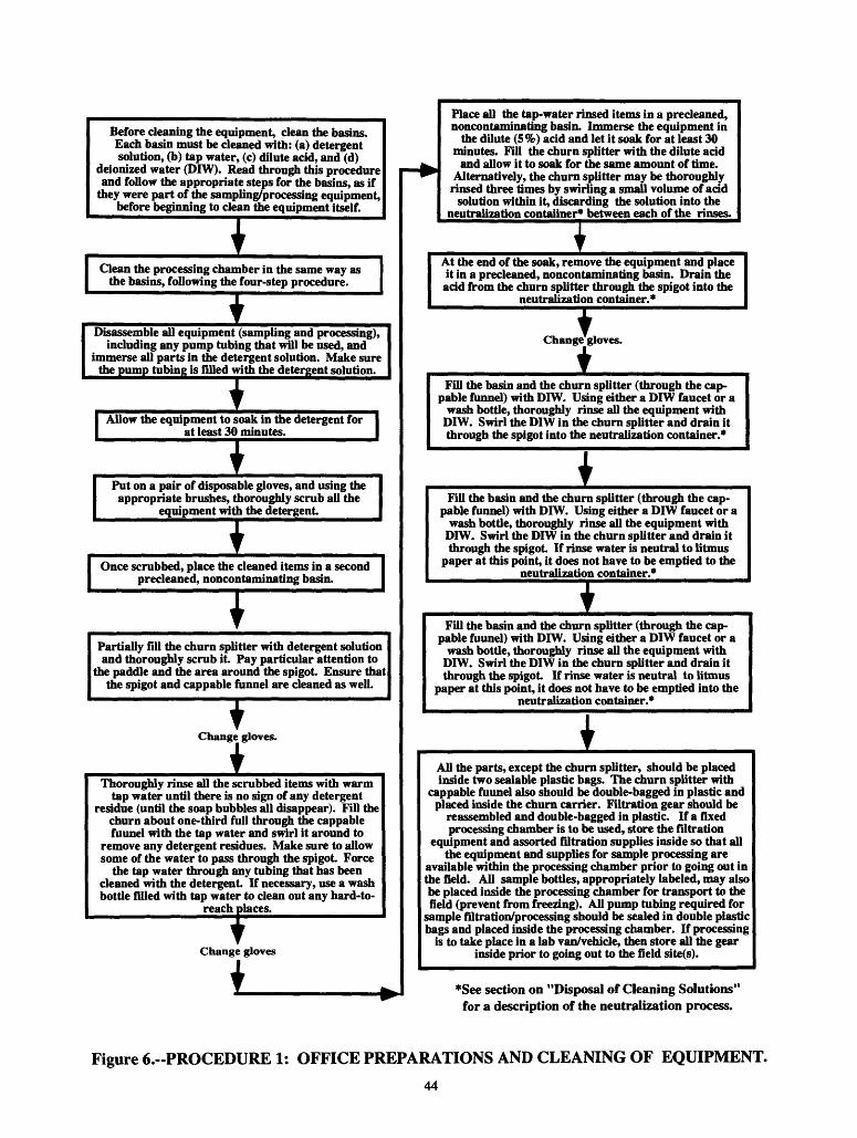
Procedure 1: Office preparations and cleaning of equipment............................................. 41Rationale....................................................................................................................... 41Requisite supplies......................................................................................................... 41Procedure...................................................................................................................... 41
Procedure 2: Field rinsing of equipment prior to sampling ................................................ 45Rationale....................................................................................................................... 45Requisite supplies......................................................................................................... 45Procedure...................................................................................................................... 45
Procedure 4: Field cleaning to prevent cross contamination between sites........................ 52Rationale....................................................................................................................... 52Requisite supplies......................................................................................................... 52Procedure...................................................................................................................... 52
Equipment list for the inorganic protocol........................................................................... 57
ILLUSTRATIONSPage
Figures 1-9. Flow diagrams for:1. Order of sample preservation................................................................. 192. Procedures for processing equipment blanks......................................... 233. Procedures for processing field blanks.................................................. 284. Procedures for splitting field samples.................................................... 295. Procedures for collecting and processing concurrent field samples....... 306. Procedure 1: Office preparations and cleaning of equipment................ 447. Procedure 2: Field rinsing of equipment prior to sampling ................... 468. Procedure 3: Sample processing and preservation-
Table 1. Target trace elements and concentrations used during evaluative testingof equipment, and sampling, processing, and cleaning procedures................ 3
2. Listing of acceptable samplers for the collection of inorganic samples ............ 8
3. List of chemical constituents evaluated during development of the protocoland the required/recommended filtration media............................................. 15
4. List and definitions of quality-control terms used in this protocol.................... 21
5. Method detection limits (MDL's) and reporting limits (RL's) for the variousconstituents covered by this protocol............................................................. 25
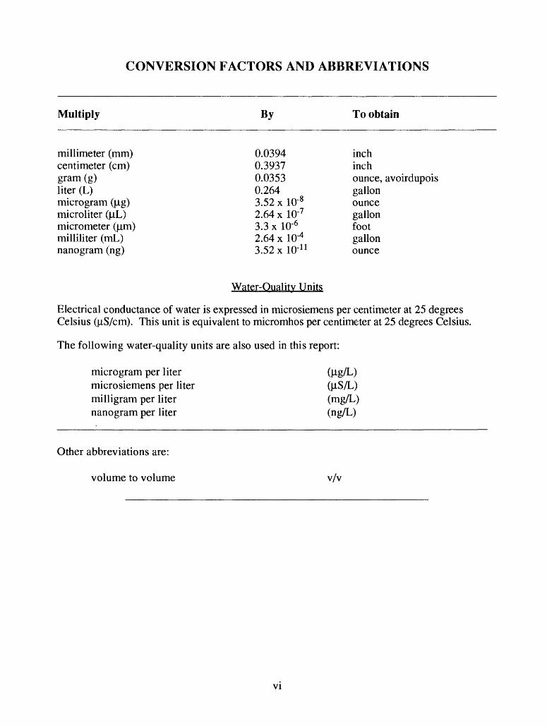
Electrical conductance of water is expressed in microsiemens per centimeter at 25 degrees Celsius (jiiS/cm). This unit is equivalent to micromhos per centimeter at 25 degrees Celsius.
The following water-quality units are also used in this report:
microgram per liter microsiemens per liter (fiS/L) milligram per liter (mg/L) nanogram per liter (ng/L)
Other abbreviations are:
volume to volume v/v
VI
U.S. GEOLOGICAL SURVEY PROTOCOL FOR THE COLLECTIONAND PROCESSING OF SURFACE-WATER SAMPLES FOR THE
SUBSEQUENT DETERMINATION OF INORGANIC CONSTITUENTSIN FILTERED WATER
By Arthur J. Horowitz, Charles R. Demas, Kathleen K. Fitzgerald, Timothy L. Miller, and David A. Rickert
ABSTRACT
Since 1987, the U.S. Geological Survey has sponsored numerous studies to evaluate its programmatic sampling, processing, and analytical equipment and procedures used for deter mining trace-element concentrations in surface water. The major finding of these evaluations was that, in many cases, the sampling and processing procedures used have resulted in trace- element concentrations which, for a number of constituents, appear to be biased by systematic and (or) erratic contamination.
A new set of guidelines and procedures was developed that would permit the production of contaminant-free (at specific reporting limits) trace-element data from filtered surface-water samples. These guidelines and procedures have been incorporated into a new trace-element pro tocol. Concurrently, these procedures also were evaluated for their utility in collecting and processing water samples for the subsequent determination of other inorganic constituents (for example, nutrients and major ions) to determine if a single method for all inorganic constituents could be developed. Such a protocol was developed and is presented in this report.
The new protocol represents a significant change in U.S. Geological Survey guidelines for the collection and processing of water samples for subsequent chemical analysis. It is intended to lead to the production of filtered inorganic-constituent data that are both defensible and inter- pretable at the microgram-per-liter level. The protocol contains detailed minimum, as well as recommended, quality-control requirements.
INTRODUCTION
Since 1987, the U.S. Geological Survey (USGS) has sponsored a number of studies to eval uate its sampling, processing, and analytical procedures for filtered water samples. The major findings of all these studies were that existing USGS sampling and processing procedures and equipment were inadequate to produce contaminant-free trace-element data on a consistent basis (unpublished Office of Water Quality (OWQ) Technical Memorandums 91.10 and 92.12 located in the USGS Office of Water Quality, MS 412, Reston, VA 22092). This has led to the devel opment of an entirely new set of guidelines and procedures that permits the production of con taminant-free (at specific reporting limits) trace-element data. These guidelines and procedures were incorporated into a new protocol for collecting and processing filtered surface-water sam ples for trace-element analysis. Concurrently, these procedures were found to be applicable to other inorganic constituents (nutrients and major ions).
The new protocol has been evaluated for its applicability to trace elements, nutrients, and major ions; it has not been tested for radiochemical constituents. However, there is nothing in the current protocol that appears to be inconsistent with the collection and processing of water samples for the subsequent determination of radiochemical constituents. However, users intend ing to follow these procedures for radiochemical samples should, at least initially, perform more than the minimum number of quality-control checks to ensure the applicability of these methods for radiochemical sampling.
Currently, it appears as if the ambient concentrations of many dissolved trace elements, at least in large rivers, are in the nanogram-per-liter (ng/L) range (unpublished OWQ Technical Memorandum 91.10 located in the USGS Office of Water Quality). However, the USGS oper ational program currently lacks the sampling, processing, and analytical capabilities to work at these ultra-low levels. Therefore, initially, the new protocol is intended to permit accurate quan tification of trace elements in filtered water at the microgram-per-liter (fig/L) level, which is the concentration level at which analytical work is routinely reported and at which most Federal drinking-water regulations for trace elements have been established. Once the new protocol is in place and as experience and capabilities improve in standard use, plans are to develop a com panion nanogram-per-liter protocol which will include mercury as well as the constituents cov ered by this protocol. Field and laboratory tests carried out during the course of the development of this protocol show that it probably is usable, in its current form, down to levels as low, or low er than 200 ng/L.
This protocol was not specifically evaluated for use in collecting samples for either mercury or radiochemical analyses. For a few mercury blanks that have been processed using the protocol, concentrations have been as low as less than 30 ng/L, and routine values below 100 ng/L have been achieved. It is believed that radiochemical constituent blanks should also be within acceptable ranges.
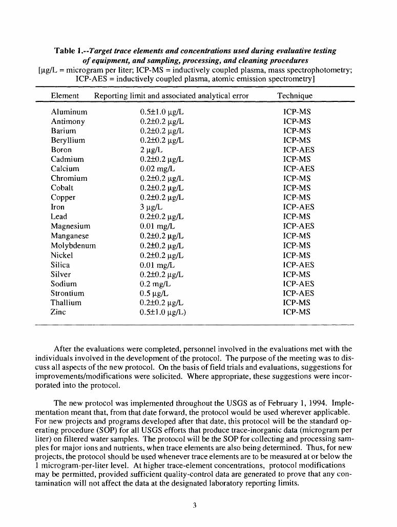
The tests and evaluations for the new protocol entailed the examination of sampling and processing equipment and sampling and processing procedures. In addition, a series of cleaning techniques for sampling and processing equipment were designed and evaluated. Finally, a series of limited field tests, including side-by-side comparisons with non-USGS personnel, were conducted and evaluated. The list of trace elements evaluated in these tests is given in table 1. Note that the target concentrations are substantially below the microgram-per-liter reporting level that the protocol was intended to meet and wherever feasible were set at levels at least 50 percent below the proposed reporting limits (table 1). This was done intentionally to ensure that, even when summed, the potential contamination from the equipment, sampling and processing procedures, and cleaning techniques would be negligible compared to the designated reporting limit.
Prior to release for general use, the new protocol was field-tested and evaluated in a limited number of USGS offices in different parts of the Nation for a period of several months. The pur poses of these evaluations were (1) to determine if the protocol could be used in a wide variety of environmental settings and to identify any problems likely to be encountered with its use, (2) to establish a group of individuals who could act as local sources of expertise with the protocol to facilitate the subsequent training of additional personnel, and (3) to carry out a side-by-side comparison of processing techniques employing both disposable-capsule and plate-type filters. Further, the offices where the evaluations were held would become the sites for training other personnel.
Table 1. Target trace elements and concentrations used during evaluative testing of equipment, and sampling, processing, and cleaning procedures
[{ig/L = microgram per liter; ICP-MS = inductively coupled plasma, mass spectrophotometry; ICP-AES = inductively coupled plasma, atomic emission spectrometry]
Element Reporting limit and associated analytical error Technique
After the evaluations were completed, personnel involved in the evaluations met with the individuals involved in the development of the protocol. The purpose of the meeting was to dis cuss all aspects of the new protocol. On the basis of field trials and evaluations, suggestions for improvements/modifications were solicited. Where appropriate, these suggestions were incor porated into the protocol.
The new protocol was implemented throughout the USGS as of February 1, 1994. Imple mentation meant that, from that date forward, the protocol would be used wherever applicable. For new projects and programs developed after that date, this protocol will be the standard op erating procedure (SOP) for all USGS efforts that produce trace-inorganic data (microgram per liter) on filtered water samples. The protocol will be the SOP for collecting and processing sam ples for major ions and nutrients, when trace elements are also being determined. Thus, for new projects, the protocol should be used whenever trace elements are to be measured at or below the 1 microgram-per-liter level. At higher trace-element concentrations, protocol modifications may be permitted, provided sufficient quality-control data are generated to prove that any con tamination will not affect the data at the designated laboratory reporting limits.
For existing projects and programs that collect samples for inorganic analyses, the protocol should be applied as the SOP as soon as possible. This may take a year or more to implement in all programs and projects. Investigations in the National Water-Quality Assessment (NAWQA) Program began using the protocol, as modified for ground water, in a pilot manner during the summer of 1993. For the National Stream Quality Accounting Network (NASQAN) and the Hydrologic Benchmark Network, the protocol will become SOP sometime after April 1995. This timing will coincide with the implementation of a redesigned NASQAN program, in which the protocol will be used for major ions and nutrients. However, depending on the redefined objectives, the program may not routinely include trace elements in filtered samples.
Throughout this protocol, the terms "required" and "recommended" will appear. If the term "required" is used, no other alternatives are considered acceptable, and the user must follow the procedure or use the piece of equipment exactly as it is described. If the term "recommend ed" is used, one or several alternatives are considered acceptable and the user has an option(s) about which procedure, or which type of equipment can be used. In most cases where recom mendations are made in this protocol, a preference also will be stated. Where a preference is given, if the user opts for selecting a procedure, or type of equipment which is not the preferred choice, it is incumbent upon the user to perform more than the minimum number of quality- assurance (QA)/quality-control (QC) checks to determine the quality of the results.
PURPOSES, OVERVIEW, AND ORGANIZATION OF THIS PROTOCOL
Purposes
The purposes of this document are to:
1. Provide a detailed description and explanation of a protocol for the preparation and use of sample collection and processing equipment to obtain contaminant-free samples for analysis of inorganic constituents at current reporting limits in filtered surface-water samples.
2. Describe minimum and recommended QA/QC procedures.
3. Describe adequate procedures for the field cleaning of equipment.
Overview
Whenever possible, explanations are provided so that the user is made aware of why certain steps have been included in the protocol, and what problems they are designed to address. These explanations are included with the intent of raising the user's awareness of the multiplicity of potential sources of contamination. Users should realize that two of the most important factors in avoiding/reducing sample contamination are:
1. An awareness of potential contaminant sources, and
2. Strict attention to the work being done.
These two factors should be viewed as being equally as important as actually following the protocol itself.
Other than carelessness itself, the two biggest sources of contamination of samples for inorganic analysis are:
1. Improperly cleaned and maintained equipment, and
2. A variety of atmospheric inputs (dust and debris from the field vehicle, from the sampling platform, and from the local environment).
Only those devices that contain no metal parts that might come in contact with the sample will be used to collect samples. All the parts of samplers to be used for the collection of materials for subsequent inorganic analysis, and actually come in contact with the sample, must be composed of uncolored or white polypropylene, polyethylene, Teflon, or other suit able nonmetallic material.
A number of the procedures and precautions described in this protocol are intended to en sure that all requisite sampling and processing equipment are adequately cleaned prior to taking them into the field. Precautions also are detailed to maintain the cleanliness of the equipment prior to actual use. Because cross contamination is always a possibility, and many sampling trips entail the collection of more than one sample at more that one site, detailed procedures are pro vided for cleaning and preparing equipment between sites. Finally, because atmospheric inputs appear to be a major source of potential contamination, some existing equipment will be modi fied (most notably the churn splitters) and all sample processing and preservation will be carried out within a controlled environment designed to reduce atmospheric inputs and (or) cross con tamination (for example, the introduction of processing and preservation chambers).
Organization
This protocol is divided into a number of specific procedures, which will be selected depending on:
1. The inorganic constituents for which the water samples are being collected, and
2. The phase of the sampling effort:A. Cleaning of equipment in District and field offices,B. Presampling field rinsing,C. Sample processing and preservation, andD. Field cleaning to prevent cross contamination between sampling sites.
The procedures include:
Procedure 1. Office Preparations and Cleaning of EquipmentProcedure 2. Field Rinsing of Equipment Prior to SamplingProcedure 3. Sample Processing and PreservationProcedure 4. Field Cleaning to Prevent Cross Contamination Between Sites
QUALITY ASSURANCE
Users of this protocol should always bear in mind a number of general considerations. Trace-element, as well as other inorganic constituent, contamination can be separated into two broad components: (1) systematic, and (2) unpredictable/erratic. The purpose of this protocol, and the selection of certain samplers and the exclusion of others, is to minimize the systematic component. The unpredictable/erratic component will remain; therefore, the use of this pro tocol does not guarantee that all samples collected and processed following these proce dures will automatically be contaminant-free at the stated method detection limits (MDL) or laboratory reporting levels. Additionally, individuals engaged in water-quality sampling and processing activities need to pay constant attention to their surroundings and to what they are actually doing so that they are always aware of, and attempt to avoid/eliminate, potential sources of sample contamination. Even then, no protocol is likely to be so detailed, nor each user so skilled, that the potential for contamination is nonexistent. Thus, even strict adherence to this protocol does not justify or exempt users from carrying out adequate QC sampling; QC samples blanks, split samples, concurrent samples, reference samples-are needed in every USGS program and project to define the quality of the collected environmental data. Guidelines for use of QC samples for inorganic constituents in filtered samples are includ ed in this protocol. Finally, individuals engaged in the collection and processing of water- quality samples require sufficient training to collect samples and to follow this protocol adequately. These types of activities are not for the inexperienced, and such personnel should not be expected nor required to perform them.
In summary:
1. All filtered inorganic water-quality samples, including those for analysis of trace elements at the microgram-per-liter level, must use this protocol.
2. Adequate use of QC measures-blanks, replicates, and so forth-must accompany all filtered inorganic samples, the extent of which will depend on the specific objective(s) of the sampling program.
3. Individuals who use the protocol must first be trained in its proper use.
ACQUISITION OF MATERIALS, SUPPLIES, AND EQUIPMENT
The type and quality of equipment used in this protocol can markedly affect the quality of the chemical results. Therefore, the USGS has arranged for its Quality of Water Service Unit (QWSU) in Ocala, Florida, to purchase, quality assure (the required chemical analyses will be performed in the USGS National Water Quality Laboratory (NWQL), and supply offices with most materials, supplies, and equipment identified for use in this protocol. These items, and no substitutes, must be used by the USGS in microgram-per-liter trace-element, as well as other inorganic, work effective February 1, 1994. The "Equipment List for the Inorganic Protocol" describes the materials, supplies, and equipment needed for this protocol and their sources.
FIELD VEHICLES
The USGS uses a variety of field vehicles during the course of its activities. Many of these vehicles are used for more than one purpose, including water-quality sampling and processing operations. Experience using current sampling and processing procedures has shown that sam-
pie contamination is much more likely to occur when multiuse vehicles are employed for water- quality sampling and processing (for example, problems associated with mercury contamination from elemental mercury used in some stream gaging operations). Therefore, it is recommended that all water-quality sampling and processing be restricted to vehicles designated for that pur pose. If, in spite of this recommendation, multiuse vehicles still are employed for water- quality sampling and processing, the user must employ portable processing and preserva tion chambers rather than a permanently installed processing chamber (see "Modification/ Construction of Equipment"). Further, it is incumbent upon the user to perform more than the minimum number of QA/QC checks (especially field blanks) to determine the quality of the results.
Even when a designated water-quality field vehicle is employed during the collection and processing of water samples for the subsequent determination of dissolved inorganic constitu ents, every effort must be made to keep the area designated for sample processing and preserva tion free of dirt and dust as well as any metallic objects. Metallic objects, such as sounding weights and bridge cranes, should not be stored in the same area where sample processing/ preservation occurs. Further, if no dust-proof barrier is between the vehicle's cab and the working (processing) area, it is strongly recommended that such a barrier be installed. The purpose of the barrier is to eliminate the potential entry of a variety of contaminants associated with the personnel riding in the front of the vehicle, as well as contaminants that may enter through open windows. Finally, if metal cabinets or shelving currently are in the vehicle and cannot be replaced, at a minimum, they should be covered with plastic sheeting.
SELECTION OF SAMPLING DEVICES
On the basis of comparisons done on the Mississippi River (unpublished OWQ Technical Memorandums 91.10, 92.12, and 92.13 located in the USGS Office of Water Quality), as well as other experiments, it has been shown that a number of samplers in current use can contaminate water samples at the microgram-per-liter level. Data have shown that, although some samplers are cleaner than others, no sampling devices currently in use can be cleaned sufficiently with either native water or deionized water (DIW) alone to completely eliminate contamination at the microgram-per-liter level. The following samplers, DH48, DH59, DH76, D74, P61, P63, and P72 produce unacceptably high levels of trace-element contamination and their use for col lecting trace-element samples is to discontinued (unpublished OWQ Technical Memorandum 92.12 located in the USGS Office of Water Quality). Some of these samplers may be acceptable for other inorganic constituents such as major ions and nutrients. If they are used for non-trace- element sampling, it is incumbent on the user, employing appropriate quality-control samples and procedures, to prove that they do not add contaminants for the constituent(s) of interest and to document this information.
The D77 sampler with a standard plastic bottle, the D77 with a Teflon sampler bottle, the D77 with a collapsible bag, and the frame-type (3- and 8-liter) sampler with either a rigid bottle or a collapsible bag appear to be the least contaminating samplers currently in use for trace- element samples. Extended experiments using the cleaning procedures (Procedure 1) document ed in this protocol were done to evaluate the samplers listed above. The evaluations showed that all the listed samplers were acceptable for use, at the microgram-per-liter level, after they had been cleaned following the procedures outlined in this protocol. By inference, since the same sampling bottles, caps, and nozzles are used in the DH 81 as in the D77 sampler, the DH81 is also an acceptable sampler at the microgram-per-liter level provided that the metal rod is covered
with plastic shrink-wrap. AH acceptable trace-element samplers for use at the microgram- per-Iiter level are listed in table 2; the use of one or more of these types of samplers is required for the collection of samples for the subsequent determination of dissolved trace elements and is recommended for other inorganic constituents.
Table 2.--Listing of acceptable samplers for the collection of inorganic (trace-element,nutrient, and major ion) samples
D77 with plastic bottle, cap, and nozzle D77 with Teflon bottle, cap, and nozzle
Frame-type sampler with plastic or Teflon bottle, cap, and nozzle D77 or frame-type sampler with Teflon or Reynolds Oven collapsible bag, Teflon or plastic
cap and nozzle DH 81 (with "shrink-wrapped" rod) with Teflon or plastic bottle, cap and nozzle
All samplers listed in table 2 have produced acceptable blank concentrations after using the office cleaning procedures detailed in this protocol (Procedure 1). Subsequent contamination of these samplers, using a laboratory-prepared "trace-element soup," followed by the application of a field-cleaning procedure (Procedure 4) also tended to produce acceptable blank concentra tions. However, the data supporting this latter contention are not as unambiguous as for the more rigorous office-cleaning procedures. Therefore, it is recommended that, if at all feasible, separate sets of sampler bottles, caps, nozzles, and processing equipment for each sampling site, for a given field collection trip, be prepared and used at each field site. If separate sampler bottles and processing equipment for each field site cannot be arranged, users should be prepared to process more than the minimum number of field blanks, per field trip, to evaluate the cleanliness of field-cleaned equipment (see section on "Quality- Control Procedures").
PERSONNEL
As noted earlier, the sampling and processing of whole-water samples for the subsequent determination of filtered inorganic constituents must be carried out by individuals with sufficient training to follow this protocol adequately. Although, in the past, water-quality sampling has been performed by one person, extended experience with the sampling and processing pro cedures described in this protocol has shown that, at a minimum, this is a two-person op eration. This two-person requirement is to be followed regardless of the type of sampling site, or the weather conditions at the time of sampling. Therefore, even if the sampling site is a small wadeable stream and the weather is warm and sunny, two individuals still will be re quired to collect and process water samples for subsequent inorganic constituent determinations.
Upon arrival at a sampling site, one individual is designated as "dirty hands" whereas the second is designated as "clean hands." All operations involving contact with the sampler bottle itself, the transfer of sample from the sampler bottle or bag to the churn splitter, and all actual sample processing are handled by the individual designated "clean hands." All operations in volving preparation of the sampler (except the sampler bottle itself), including operation of the bridge crane, contact with the metallic parts of the sampler, collection of the sample itself, are handled by the individual designated "dirty hands." Initially, this appears to be a fairly clear-cut
and separate division of responsibilities. In fact, the completion of the entire protocol requires a good deal of coordination and practice (for example "dirty hands" will have to open the outer plastic bag housing the churn splitter while "clean hands" will have to open the inner plastic bag and cappable funnel and transfer the sample from the sample bottle to the churn). Therefore, even after individuals have undergone the appropriate training necessary to follow this protocol, it is strongly recommended that sampling and processing teams practice the procedures before employing them at actual field sites.
MODIFICATION/CONSTRUCTION OF EQUIPMENT
Churn Splitters
As noted in the Overview, one of the major sources of contamination is atmospheric inputs. When the lid of a churn splitter is removed to fill it with whole water, the large open area, even for the small 8-liter version, represents a major potential entry point for atmospheric inputs that could contaminate a sample. This may happen each time the lid is opened and could occur as many as 20 or more times at a single site, depending on the type and (or) volume of sample being obtained. To reduce the open space, churn splitters should be modified by placing a cappable, polyethylene or polypropylene funnel in the lid of the churn splitter (the funnel can be made by cutting the bottom section off of a 1-liter sample bottle and inserting it into a 1-inch hole drilled into the lid of the churn splitter; the bottom two-thirds of a 1-liter Nalgene sampler bottle can be used for the funnel cap). Whole water then can be fed into the churn splitter through the funnel without opening the large lid. When the churn is being filled, the cap on the funnel should only be opened far enough to allow sample entry into the churn. As a further precaution against potential contamination either entering the churn splitter, or contaminating the exterior of the churn, the splitter should be placed inside two pliable, clear polypropylene or polyethylene bags. The bags should be sufficiently large that they completely contain the churn splitter, with enough material left over such that the bags can be gathered together and kept closed. The bags are opened only enough to reach the cappable funnel each time the contents of a sampler are to be added to the churn splitter.
A further modification will be required when using the churn splitter which differs from current procedures. This entails the use of an exterior churn splitter carrier/container. The car rier is a large, covered plastic container in which the churn splitter, inside its plastic bags, will sit. The reason for the carrier is to eliminate the potential for carrying contaminants from the sampling site into the area where samples will be processed. Additionally, in exposed areas such as on bridges, the carrier will provide extra protection against atmospheric inputs, particularly material thrown up by vehicular traffic. Normally, the churn splitter is left on the road surface, or on the ground, while sampling and compositing occurs. This provides ample opportunity for soil and other assorted debris to adhere to the bottom and sides of the splitter. By placing the splitter inside a carrier, the splitter is one step removed from picking up this material. Also, the lid of the churn carrier serves a dual purpose: (1) it seals the churn splitter, inside its protective bags, from potential atmospheric contamination, and (2) it can be used as an additional wind break when the churn splitter is exposed during the transfer of sample from the sampler. Once the sample is completely collected, the churn, inside the sealed carrier, is moved to the field vehicle. At that point, the churn, inside the interior plastic bag, is removed from the carrier and brought inside the field vehicle. The carrier and the outer plastic bag, with any adhering debris, are left outside the vehicle.
The spigot on currently available, as well as existing, churn splitters is spring loaded (the system contains a metal spring inside a plastic housing) to keep it closed when not in actual use. That is, unless pressure is applied to the spigot, the spigot is kept closed by the metallic spring. The presence of the spring represents a potential source of contamination for filtered samples and especially for whole-water samples. Work continues on replacement spigots for all District churn splitters. These spigots twist open and closed and do not contain a spring.
During the course of developing this protocol, only the churn splitter was evaluated for potential contamination. Further, all the office- and field-cleaning procedures, as well as actual field trials for the protocol, were carried out using the churn splitter. The cone splitter has never been evaluated. Therefore, at least at present, users of this protocol are restricted to using the churn splitter for compositing samples and for obtaining representative whole-water samples. Until it is adequately tested, the cone splitter is not an acceptable piece of equip ment.
Processing Chambers
Processing chambers are intended to reduce/eliminate potential atmospherically-derived contaminant inputs. In dedicated water-quality vehicles, the chamber can be either a permanent ly installed nonmetallic structure or a portable unit composed of a nonmetallic frame (wood, PVC pipe) and a disposable plastic cover (also see "Preservation Chambers" below). In the case of multiuse vehicles, or for use in areas inaccessible to water-quality vehicles, a portable cham ber appears to be the only viable option. Either type of processing chamber must be amenable to normal whole-water processing procedures. For example, permanently-installed chambers must have a small access hole in their sides to permit the passage of an appropriate diameter pump tubing which will be attached to the filtration equipment. A second hole has to be made in the bottom of the chamber to permit disposal of cleaning solutions and filtered water. In the case of a portable chamber, an access hole for pump tubing will still be required. However, the siting of a second opening, for fluid disposal, may be awkward. The requirement for the disposal of unwanted fluids can be met through the use of a "toss" bottle inside the chamber. Obviously, this will have to be emptied periodically; ideally, this should be done between samples (for ex ample, when the disposable cover is changed, pour the unwanted liquids into a scalable container for later, and appropriate, disposal).
There is no set design for either fixed or portable processing chambers, but all the materials used in their construction must either be nonmetallic, or, when metal parts are used, they must be completely embedded in nonmetallic material.
Preservation Chambers
Sample preservation should not be carried out in the same chamber as sample processing. (NOTE: If nitric acid is the only preservative being used, it can be added in the processing cham ber AFTER all other samples have been processed and removed from the chamber.) This is to prevent possible sample contamination from the spillage or residues of the chemicals used in sample preservation. At the same time, it is inadvisable to open sample bottles to add various chemical preservatives in the open (1) because of the potential for sample contamination from atmospheric inputs, and (2) to limit the amount of possible cross contamination from the preser vatives themselves. Therefore, a chamber in which sample preservatives are added is required. A chamber of this type should be as simple as possible. The frame should be made from a non- metallic material (wood, PVC pipe) and the frame cover can be a thin-walled, transparent,
10
disposable plastic bag. As field personnel follow the order of sample preservation procedure described later in this protocol, the preservation chamber cover must be changed every time the procedure calls for a change in gloves.
Where space inside the field vehicle is extremely limited, it may not be feasible to have both a processing chamber and a preservation chamber set up at the same time. Under such circumstances, the processing chamber may also function as a preservation chamber. All that would be required is a change of disposable plastic cover after all processing is complete, but prior to the beginning of any sample preservation, so long as the cover used during preservation is fitted interior to the chamber frame rather than surrounding the frame. On the other hand, if sufficient space is available, multiple preservation chambers can be employed so that all required preservation steps can be carried out without having to change the disposable covers. The use of multiple preservation chambers can save a substantial amount of time when a number of different preservatives are required.
DEIONIZED WATER
A careful reading of this protocol, and familiarity with the various cleaning procedures outlined in it, will show that copious amounts of deionized water (DIW) will be required in the office as well as in the field. This water must be quality controlled by occasionally submitting samples for analysis and, at least monthly, checking the specific conductance to make sure that it is less than 1 microsiemens per centimeter (unpublished OWQ Technical Memorandum 92.01 located in the USGS Office of Water Quality). Many DIW units come without a final, in-line filter after the DIW passes through the deionizing columns. It has been shown that many of the systems lacking a post-column, in-line filter have a tendency to permit some of the deionizing resins to pass out with the DIW. Initially (with a new set of columns), DIW residues containing these resins may contribute to the major ion content of a sample. After some use, the beads may also contribute other cations (trace elements) which were removed from the water during pas sage through the columns. Therefore, it is strongly recommended that a 0.45-|im post- column filter be added to all deionizer systems to prevent the inclusion of these resins with the DIW. Finally, locally-produced DIW is NOT to be used for either annual equipment or field blanks (see section on "Quality-Control Procedures").
CHOICE OF ACID FOR THE VARIOUS CLEANING PROCEDURES
Most individuals working with low-level inorganic water-quality determinations take spe cial care in precleaning their equipment before going out in the field; additional care and clean ing are used at the sampling site and between sampling sites. Invariably, at least some of the various cleaning procedures entail the use of mineral acids. Typically, the acids are dilute (5 to 10 percent volume to volume (v/v). The choice of acid(s) varies from one individual to another, but typically is either nitric (HNO3) or hydrochloric (HC1) acid. Shiller and Boyle (1987) and Windom and others (1991) use HC1, while many other researchers use HNO3. In protracted cleaning procedures that go beyond the needs addressed in this protocol, both acids are used. Most trace-element geochemists tend to prefer HNO3 because it is a strong oxidizer and tends to be more contaminant free than HC1; as such, it is usually the acid of choice for cleaning proce dures. However, if the filtered samples are to be analyzed for nutrients, HNO3 may represent a potential contaminant (nitrate, total nitrogen) and should be avoided.
11
To eliminate potential confusion, as well as a potential source of contamination for deter minations other than trace elements, HCI will be used exclusively throughout this protocol as the mineral acid employed for any acid cleaning solution. Appropriate volumes of dilute HCI shall be made up as needed from concentrated HCI (12N, specific gravity 1.19, trace element- free grade) which, because of Department of Transportation shipping requirements, cannot be supplied by the QWSU. It will have to be purchased directly from an appropriate vendor. Work ing with acid will require proper ventilation and similar safety precautions to those used with acid preservation ampoules (such as gloves and safety glasses). Dilute acid solutions used to clean equipment should not be stored and reused. Although this may appear wasteful, and may create certain disposal problems, reuse of acid is not acceptable because of potential cross- contamination problems associated with storage and subsequent reuse. Used and (or) excess acid must be properly disposed of (unpublished Water Resources Division Memorandum No. 94.06 located in the USGS Office of Water Quality).
DISPOSAL OF CLEANING SOLUTIONS
One of the cleaning solutions that is used in this protocol is dilute HCI. Because the clean ing solution can only be used once, and may not be recycled, appropriate disposal is required. Typically, acidic cleaning solutions are neutralized prior to disposal. Although regulations vary from State to State, and even within States, the basic procedures for neutralizing the solution are simple, easy to perform, and do not require any safety procedures beyond those already required for dealing with acid preservative ampoules.
The neutralization process can be accomplished with a variety of materials including agricultural limestone (available from garden supply centers), soda ash (used to control the pH in swimming pools), baking soda (available in supermarkets), crushed shells, or landscape mar ble chips (available in garden supply centers). The recommended procedure entails the use of landscape marble chips that normally come in 1- to 2-centimeter pieces and are sold in 25 to 50 pound bags. Neutralization should be carried out in 25- to 30-liter white or clear polyethylene containers (carboys or jerricans). Cover the bottom of the container with a layer of closely- packed marble chips. Making sure that proper safety procedures are taken, SLOWLY pour the dilute acid cleaning solution into the container; the reaction should be fairly mild since the sur face area of the chips is relatively small. Do not fill the container more than one-half to three- fourths full. This procedure should be performed in a well-ventilated room, under a fume hood, or outside of a building, as the neutralization reaction leads to the evolution of carbon dioxide (CO2). When the solution is neutral to litmus paper, it can be poured down a drain using copious amounts of tap water to wash it down. As more and more of the dilute acid solution is neutral ized, the marble chips will dissolve. When a small number of chips remain, a new layer of ma terial should be added before any more neutralization is done.
Although agricultural limestone, soda ash, baking soda, and (or) crushed shells can be used to neutralize acidic cleaning solutions, they are not recommended. The reason is the generally fine-grained nature of these materials. Fine-grained materials have large surface areas which provide a larger number of reaction sites than the courser marble chips. This results in a more rapid reaction with the fine-grained materials, which could cause solutions to overheat and (or) overflow the neutralization container.
12
SELECTION OF FILTRATION MEDIA
The almost universally accepted, as well as the traditional USGS operational definition of a dissolved constituent is what is contained in a water sample after it has passed through a 0.45-um membrane filter. Recent evidence indicates that this definition does not ensure that the conditions for a consistent operational definition are met. The definition is too nonspecific. Filtered sample concentrations (especially for such constituents as iron, aluminum, manganese, copper, zinc, and lead) may be affected by many other factors such as filter type, filter diameter, filtration method, volume of sample processed, suspended-sediment concentration, suspended- sediment grain-size distribution, concentration of colloids and colloidally-associated trace ele ments, and concentration of organic matter (Horowitz and others, 1992). These factors may be as important as the filter pore size itself because during the course of sample processing they act to continuously reduce the nominal pore size of the membrane. Some of the factors cited above are beyond the control of field personnel, whereas others can be controlled. In addition, exper iments were conducted to evaluate the contamination potential of various membrane filters (un published OWQ Technical Memorandums 92.13 and 93.05 located in the USGS Office of Water Quality). For these reasons, and to reduce between-sample variability as much as practicable, this protocol will specify particular items of equipment and procedures (filter brand, filter diam eter, volume of sample to be processed). USGS personnel are required to follow these specifi cations.
Traditionally, the USGS has used plate filters to process whole-water samples to obtain filtrates for the determination of dissolved inorganic constituents. This usually means the use of a 142-mm, 0.45-um pore size, tortuous path filter in a nonmetallic backflushing system using a peristaltic pump. For purposes of a "clean" protocol, these systems are usable. However, the use of plate filters involves a good deal of handling (to seat the filters, process the samples, clean the system between samples). As a result, they need to be opened and closed frequently. Fur ther, the exposed (open to the air) position of the sample bottles during filtration has led to the need for processing chambers (see above). Due to the widespread use of these plate filters, a series of procedures for collecting and processing water samples for the subsequent determina tion of some inorganic constituents was developed and is presented in the following pages. Users are advised to preclean, preload, and precondition as many plate filter units as possible prior to going out in the field to collect and process samples. If at all possible, users should try to obtain a sufficient number of filtration units to eliminate the need for cleaning them in the field.
As a consequence of the increased handling and cleaning requirements associated with the use of large plate filters and the difficulties of contaminant-free field cleaning between uses, users are advised that plate filters only may be used to obtain filtered sam ples for the subsequent determination of nutrients, some major ions (see table 3), and (or) radiochemicals, but not for trace elements.
A number of years ago, the USGS recommended the use of 0.45-um pore size capsule fil ters to eliminate the clogging problems associated with filtering samples containing large con centrations of suspended sediment because the filters have a surface area roughly three times larger than a 142-mm plate filter (unpublished OWQ Technical Memorandum 80.22 located in the USGS Office of Water Quality). This type of filter was used by Windom and others (1991) to produce low-level (nanogram per liter) dissolved trace-element data on a number of east coast rivers. Testing by the USGS has shown that certain capsule filters can be used for processing
13
samples for the subsequent determination of microgram-per-liter level trace elements, nutrients, and major ions (unpublished OWQ Technical Memorandum 93.05 located in the USGS Office of Water Quality). They also may be used for radiochemical samples. Capsule filters have a number of advantages relative to the more traditional plate filters: (1) they require minimum pre- cleaning (at the microgram-per-liter level, a 1-liter DIW rinse), (2) because they are sealed units, their use will entail much less handling; hence there is much less likelihood for contamination, (3) because they have a large surface area, they are much less subject to clogging than plate fil ters, (4) they will not require post-cleaning prior to processing additional samples because they are disposable units, only intended for a single use, and (5) by altering the preconditioning pro cedures (precleaning with HC1 and DIW instead of just DIW), they may be readily usable for nanogram-per-liter procedures. The only major disadvantage associated with capsule filters is that they are about six to eight times more expensive than membrane filters. This higher cost should be offset by the savings associated with the labor savings attributable to reduced field handling, no need for between-sample cleaning procedures potentially required for plate filters, and the need to process fewer field blanks because of the decreased potential for contamination. Obviously, capsule filters are not restricted to use in processing trace-element and certain major cation samples, and can be used to process samples for the subsequent determination of nutri ents, certain major ions, and (or) radiochemicals. The decision to use traditional plate filters or the new capsule filters, for non-trace-element and certain major cation determinations, is left up to individual projects; both types of filters will be provided by the QWSU.
In summary, all the various constituents listed in tables 1 and 3 can be determined on whole-water samples filtered with capsule filters. A much more limited number of constituents can be determined on samples filtered using traditional plate filters. Table 3 lists those constit uents that must be filtered with the capsule filter, as well as those that can be determined on sam ples that have been filtered with either type of filter. Bear in mind that the capsule filter is required for those constituents only listed under the capsule filter category; where a con stituent is listed under both filter categories, the user has the option of using either type. However, even in those cases where the user has the option of using either filter type, the capsule filter is recommended.
FILTER AND FILTRATION EQUIPMENT CONDITIONING METHODS
Previous protocols have required that plate filtration systems and filters be conditioned prior to use. Typically, this has entailed the initial processing of up to 500 mL of native water. The filtrate from this aliquot is used to rinse sample bottles and is then discarded prior to col lecting the actual sample. Most experienced field personnel have encountered situations where water samples have contained algae or suspended sediment at such levels that the filters will almost or completely clog during this conditioning step.
Experiments were carried out to see if this problem could be eliminated by substituting DIW for native water to condition the filters and filtration systems prior to processing actual samples. The studies have shown that when DIW is used, it may adversely affect constituent concentrations, by dilution, through the incomplete removal of entrained DIW. The dilution ef fect is about 10 percent. Due to the limited nature of the tests, the only affected concentrations observed were above 200 jo,g/L (noted for iron and possibly strontium) (unpublished OWQ Tech nical Memorandum 92.13 located in the USGS Office of Water Quality). That is, if DIW is used instead of native water to condition the filtration system, constituent concentrations above 200 |ig/L may be negatively biased by as much as 10 percent. Because the analytical precision and
14
Table 3. List of chemical constituents evaluated during the development of the protocol andthe required/recommended filtration media
Constituent Capsule filter Plate filter
Aluminum X
Antimony X
Barium X
Beryllium X
Boron X
Cadmium X
Calcium X
Chromium X
Cobalt X
Copper X
Iron X
Lead X
Lithium X
Manganese X
Magnesium X
Molybdenum X
Nickel X
Silica X
Silver X
Sodium X
Strontium X
Thallium X
Uranium X
Zinc X
Nutrients (Nitrogen, Phosphorus) X
Anions (Chloride, Sulfate) X
Radiochemicals X
X
X
X
X
X
X
X
The effect of filter choice on radiochemicals has not been evaluated; therefore, it is incum bent upon the user who opts for the plate filter or the capsule filter to ensure that these constitu ents are not adversely impacted.
15
accuracy of microgram-per-liter determinations is very low for low analyte concentrations, this effect could become significant at concentrations of 50 \ig/L or higher. This is viewed as a secondary problem, relative to the potential difficulties associated with preclogging during con ditioning with native water. Therefore, the procedure for plate and capsule filters described in Procedure 3 calls for conditioning with DIW.
Even though the capsule filters are highly resistant to clogging because of their large sur face areas, experiments have shown that processing as little as 250 mL of native water for pur poses of preconditioning the filters can produce a significant reduction in the concentration of a variety of trace elements (for example, iron, aluminum, copper, zinc, lead), but not nutrients or some major ions, in the filtrate. Therefore, the disposable capsule filters should be pre conditioned with DIW.
The use of DIW in lieu of native water to precondition the filtration equipment prior to fil tering samples creates one additional problem. It has always been considered good field practice to rinse sample bottles with small amounts of filtrate prior to filling them with actual samples. To maintain this practice, without adversely affecting trace-element and certain major cation concentrations (the only inorganic constituents which appear to be affected by filter clogging) on the one hand, yet limiting the possibility that the filters will be too clogged with material to permit collection of adequate volumes of filtrate without having to change filters on the other, a special set of procedures have been designed. Different procedures are required depending on whether a plate filter or a capsule filter are used to filter the samples.
The sample-processing procedure when using capsule filters is to begin to filter water for the trace-element sample (FA bottle) and collect the first 25 to 50 mL of the filtrate (the 250-mL bottle is filled to the top of the lower lip); cap and shake bottle to rinse; discard water. Then, fill the bottle to the top of the upper lip. This volume will constitute the trace-element sample (the final volume will be about 200 to 225 mL, slightly less than current requirements). If a mercury sample is to be collected, it is processed following the trace-element (FA) sample using the same bottle rinsing and filling procedure and the appropriate glass sample bottle (FAM). Next, rinse all the other sample bottles, with the total volume of rinse water being no more than 100 mL. Finally, filter sufficient water to meet the volume requirements for all the other samples.
The procedure for plate filters is to filter sufficient water to rinse all the sample bottles (no more than 100-mL total). Then filter sufficient water to meet the volume requirements for all sample bottles.
SAMPLE BOTTLES
Appropriate sample bottles can be ordered from the QWSU or the NWQL. All sample bot tles used for inorganic samples must be obtained from one of these sources to ensure that they have been adequately prepared and have undergone appropriate quality-control checks.
In the past, all sample bottles, particularly acid-rinsed (FA and RA) bottles which are sub jected to quality-control checks, have been presumed to be clean. However, experience has shown that exceptions occur. If any acid-rinsed bottles become uncapped during shipment or storage, they must be immediately discarded as their integrity has been compromised. In addi tion, as a precaution against potential sample contamination, all sample bottles are to be cleaned prior to use. Cleaning should be done contemporaneously with the Office Preparations and Cleaning of Equipment Procedures (Procedure 1). Cleaning simply entails rinsing each sample
16
bottle three times with DIW. After the last rinse, the bottle is half-filled with DIW and capped. Place all bottles for trace-element samples in scalable plastic bags. The bottles remain filled un til just prior to use during actual field sampling and processing. Cleaned bottles must be protect ed from freezing.
PUMP TUBING
During the course of various equipment and cleaning procedure evaluations, as well as dur ing actual field trials, two different types of pump tubing (silicon and C-flex) were used and test ed. The silicon tubing was found to be suitable after it had been appropriately cleaned; however, there were some instances for which detectable, but low-level concentrations of silica were quantitated. The levels ranged from 0.09 to 0.24 mg/L. In the case of the vast majority of envi ronmental samples, these concentrations are sufficiently low that they are unlikely to have a significant impact. However, in low ionic strength waters, these silica concentrations (up to 0.24 mg/L) could be significant. Therefore, users are cautioned to keep this in mind when selecting pump tubing for the processing of whole-water samples.
C-flex tubing is made from an organic copolymer. During field trials this tubing was used extensively because it is more resistant to acid than silicon tubing. Acid resistance is a factor because dilute HC1 is used in both the Office Cleaning Procedure and in the Field Cleaning Procedure (Procedures 1 and 4, respectively). Based on the field trials, C-flex tubing is appropriate for all the constituents listed in tables 1 and 3.
Although never actually employed during any of the evaluations or field trials, other stud ies have clearly shown that Teflon tubing, provided it has undergone the appropriate cleaning procedures, also would be usable with this protocol. However, Teflon tubing is not flexible and it cannot be used on its own with peristaltic pumps. Therefore, a small section of flexible tubing, to fit in the pump head, must be connected to the Teflon tubing. The only flexible tubing which should be used in this type of application is either silicon or C-flex.
Because of its relatively narrow bore, and the length required, pump tubing can be difficult to either clean initially (Procedure 1), or to clean after use between sampling sites (Procedure 4). As a result, it may be more efficient to use pump tubing only once, and then discard it. This is particularly true if the tubing has been used to process sediment-laden water and has been allowed to dry out before it has been cleaned prior to re-use. Users of this protocol should bear this in mind when selecting pump tubing as a result of the variations in the cost of procuring it (for example, Teflon tubing is by far the most expensive, as well as the most difficult to clean relative to either silicon or C-flex tubing).
SAMPLE PRESERVATION
Many of the constituents found in natural waters may not remain in a water sample long enough after sampling and processing to be determined at a later date in the NWQL. These loss es occur because of a variety of physical and (or) chemical reactions (oxidation, reduction, pre cipitation, adsorption). In some cases, the problem of loss can be addressed by determining the constituent(s) of interest in the field. However, a number of constituents simply cannot, at least currently, be determined conveniently or with acceptable precision and accuracy in the field. Therefore, various sample treatments have been developed to stabilize constituent concentra-
17
tions until the samples can be analyzed in a laboratory. The various treatments used to stabilize the composition of water samples are called preservation techniques.
Preservation may involve either a physical (for example, chilling) or a chemical (for exam ple, addition of nitric acid) treatment, or both. Unfortunately, some of the chemical treatments used to preserve certain constituents represent potential sources of contamination for other con stituents. For example, nitric acid preservation for trace-element samples can be a potential con taminant for nutrient determinations, mercuric chloride preservation for nutrient samples can be a potential contaminant for mercury determinations, sulfuric acid preservation for nutrient or chemical oxygen demand (COD) can be a potential contaminant for major anions. Therefore, care must be taken during the various preservation steps to prevent potential contamination. The prevention of contamination during preservation can be facilitated by using appropriate tech niques and by following a prescribed order in carrying out the various preservation steps (un published OWQ Technical Memorandums 90.01 and 92.08 located in the USGS Office of Water Quality).
Since many preservatives can be personally harmful, users should wear appropriate protec tive equipment (eye protection and disposable gloves). Further, the gloves should be changed after the use of certain preservatives to further limit potential cross-sample contamination. The order of preservation should be as shown in figure 1.
Traditionally, the USGS has provided preservatives in individual glass ampoules. Preser vation is carried out by breaking open the ampoules and adding their contents to processed or unprocessed water samples. These ampoules are procured under contract by the NWQL and have undergone prescribed quality-control evaluations to ensure that they are contaminant free. During some of the field trials, other methods of adding various preser/atives also were used/ evaluated. These included dropper bottles and automatic pipettes, used in conjunction with a variety of preservative reservoirs.
None of the three procedures cited above (ampoules, dropper bottles, automatic pipettes) are completely free of problems. Tests carried out by the USGS have shown that glass ampoules, even those containing Ultrex grade acid, can contaminate samples with unacceptably high con centrations of boron, aluminum, and barium, as well as potentially significant levels of silica, chromium and zinc. Thus far, the only ampoules that do not add detectable concentrations of contamination are made from Teflon. Dropper bottles may be free of contamination, but if the initial source of the preservative, or the dropper reservoir becomes contaminated during the course of their use, a number of samples may be contaminated before the user becomes aware that a problem exists. Automatic pipettes can suffer from the same problem. In addition, auto matic pipettes also require experience to be used properly. Many of them contain metal parts which can come in contact with the preservative if the pipette is not used correctly. If the pipette is used properly, this does not happen; however, if they are used inappropriately, they can con taminate the preservative and thus, the sample. Therefore, all sample preservatives required under this protocol will be provided in ampoules. If the user is not interested in the con centration of aluminum, barium, boron, silica, chromium, and zinc in a sample, then nitric acid in glass ampoules is acceptable for trace element (FA or RA) or mercury (FAM) sam ples. Obviously, glass ampoules are not a problem for nutrients (FC and RC) or other in organic samples. However, for all trace-element samples (FA or RA) for which aluminum, barium, boron, silica, chromium, and zinc are to be determined, preservatives in individual Teflon ampoules will be required and will be supplied by the QWSU.
18
Put on a fresh pair of disposable glovesand preserve all samples that require the
addition of acids such as nitric, sufluric, orhydrochloric. For example, trace elementsamples, with the exception of samples for
the determination of mercury, require nitric acid.
Using the same gloves used to add any acidpreservatives, preserve any samples for
mercury determinations with nitricacid/potassium dichromate.
Change gloves and preserve the nutrientsamples with sulfuric acid if it is a U.S.
Environmental Protection Agency type project,after which samples should be chilled.
Unpreserved nutrient samples must be chilledimmediately after the bottles are filled.
Change gloves again and complete any otherpreservation procedures, such as the additionof sodium hydroxide, zinc acetate, or copper
sulfate, that are required.
NOTE: Remember, change the preservation chamber cover every time you change gloves.
Always store your preservatives in separate sealed containers, preferably away from each other and away from any samples.
Preservative containers, once used, should be stored in separate sealed containers, such as screw-cap bottles, until proper disposal can be arranged.
Used gloves should also be stored in sealed containers, such as a lidded pail, until proper disposal can be arranged.
Figure l.--Order of sample preservation.
19
SAMPLE SHIPMENT
The issue of sample shipment is fully discussed in OWQ Technical Memorandum 92.06 (unpublished memorandum in the USGS Office of Water Quality). Suggestions dealing with this subject follow.
All sample bottles must be clearly labeled with a waterproof marker so that the NWQL can sort them for appropriate analysis. The minimum information required for each bottle is the site identification number, the date, the time, and the sample designation code (RA, FA, RC, FC, FAM, and so forth). It is also useful, but not mandatory, to write the appropriate schedule num- ber(s) on the bottles. Many field personnel find it more convenient to prelabel their bottles with preprinted labels prior to going into the field. Such labels need to be protected from water, pre servatives, or water and preservative spillage to prevent smearing. Remember, a bottle with an unreadable label means a wasted sample. Further, inorganic sample bottles should be stored in scalable plastic bags before going to the field. This will help limit potential contami nation during transit and prior to filling.
Remember to include a NWQL Analytical Services Request Form (Log-In Sheet) for each sample sent to the laboratory. Fill in the appropriate sections of the form; remember to retain the carbon copy. The Request Forms must be shipped together with the appropriate samples. To prevent damage to the forms (soaking due to sample spillage or melting ice), place them inside a scalable plastic bag before placing them in an appropriate shipping container. For coolers, tape the bag containing the forms to the inside of the lid.
QUALITY-CONTROL PROCEDURES
The intent of this section is to provide users of this protocol with a few simple guidelines regarding the why and how of quality-control samples relative to the collection, processing, and analysis of filtered water samples for the subsequent determination of inorganic constituents. This section is not intended to be an exhaustive discussion of quality-control principles and (or) techniques, nor of how quality-control data should be used to interpret environmental data. The terms used in this section are consistent with definitions issued by the USGS Branch of Quality Assurance (BQA) (unpublished Water Resources Division Memorandum 91.09 located in the USGS Office of Water Quality); however, some of the terms have been refocused and additional terms included to address the needs of this protocol (table 4).
The purpose of obtaining QC samples is to (1) assess the adequacy of the cleaning proce dures and the level of contamination in the environment in which samples are collected and pro cessed, and (2) to assess the quality, reliability, and precision (reproducibility) of the data generated. Quality-control data also can be used to determine if the difference between chemical concentrations measured for different samples are statistically significant. Quality-assurance procedures and quality-control samples are not a luxury, nor should they be viewed as an option, to be included or omitted at the discretion of the operator. QC samples are a requisite for any sampling and analysis program because without quality-control information, the quality of collected environmental data can neither be evaluated nor qualified. If data quality can not be evaluated, then the data must be viewed as uninterpretable, or at best only margin ally interpretable, because the user has no means of knowing the associated errors. Thus, what appear to be differences between samples obtained at the same location over a period of
20
Table 4.--List and definitions of quality-control terms used in this protocol
Equipment blank (sampler + splitter + pump + filter) - a blank solution subjected to the same aspects of sample collection, processing, preservation, transportation, and laboratory handling as an environmental sample, but is processed and shipped from the relatively controlled environment of an office or laboratory.
Sequential equipment blanks - a series of blank samples (sampler blank, followed by splitter blank, followed by pump blank) collected in order after each step in the generation of an equipment blank.
Field blank - a blank solution that is generated under actual field conditions and is subjected to the same aspects of sample collection, field processing, preservation, transportation, and laboratory handling as the environmental samples.
Sequential field blanks - a series of blank samples (sampler blank, followed by splitter blank, followed by pump blank see above) collected in order after each step in the generation of a field blank.
Source-solution blank - solution that is considered free of analyte(s) of interest and is stock solution used to develop other blank samples; source-solution blank is collected in a relatively protected area and used to verify the composition of the stock solution.
Sampler blank - a blank solution that is poured through the same sampler to be used for collecting environmental samples.
Splitter blank (sampler + splitter) - a blank solution that is poured into the same sampler and then processed through the same splitter to be used for environmental samples.
Pump blank (sampler + splitter + pump) - a blank solution that is poured through the same sampler, then processed through the same field splitter, and then is pumped by a peristaltic system through the same tubing to be used for environmental samples.
Replicate (duplicate/triplicate/split) samples - a set of environmental samples collected in a manner such that the samples are thought to be essentially identical in composition. Replicate is the general case for which a duplicate is the special case consisting of two sequentially-collected samples and for which a split is the special case in which two or more samples are generated from one. Different types of replicate samples may yield somewhat different results because they are collected in dynamic hydrologic settings.
Split field sample - a type of replicate sample in which one sample is split into two or more subsamples contemporaneous in time and space.
Concurrent field sample - a set of replicate samples which are composed of alternating subsamples composited contemporaneously in two or more collection containers.
Standard/Reference material sample - a solution or material prepared by a laboratory whose composition is certified for one or more properties so that it can be used to assess a measurement method or for assigning concentration values of specific analytes.
21
time, or differences between samples collected at about the same time but from different loca tions, may actually represent errors introduced by the method and the application of the methods for sampling, sample processing, or laboratory analysis.
The types of errors associated with chemical data produced from environmental samples come from a number of sources. For simplicity, these errors can be divided into three general categories: (1) contamination (field or laboratory), (2) sampling error, and (3) analytical error. The various types of quality-control samples discussed in the following sections are designed to measure the magnitude of these various sources of error.
Equipment Blanks
An equipment blank is intended to assess the potential contamination levels associated with sampling and processing equipment, and should be produced for all sample-collection and processing equipment used in this protocol, as well as other protocols. When the cleaning pro cedure is followed for the first time, or when new items of equipment are going to be used for the first time, and prior to the collection of any actual environmental samples, an equipment blank must be run in the office. This blank should be run after all the equipment has been cleaned and prepared for field use. An equipment blank is required at least once a year. No samples should be collected and processed until the annual equipment blank data have been received and reviewed by the project chief or the District Water-Quality Specialist, and show that the equipment is either free of contamination or the levels are low enough as to be insignificant at current analytical limits. Equipment blanks must be run with Inorganic-Free Blank Water (IBW) obtained for that purpose from the QWSU. The procedure entails several steps and involves the collection of a group of sequential equipment blanks while producing the actual equipment blanks (fig. 2).
1. Collect, store in an appropriate bottle labeled "Source Solution Blank," and ade quately preserve an aliquot (at least 250 mL) of the IBW water. Record and keep on file, in the field notes, the date and lot number of the blank water and the preser vative obtained from the NWQL. Always use preservative from the same lot num ber for an entire sampling trip for both the actual and the quality-control samples.
2. Fill the sampler bottle with IBW; attach sampler cap and nozzle; pour an aliquot (at least 250 mL) through the nozzle into the bottle labeled "Sampler Blank." Preserve the sample.
3. Pour the remainder of the IBW from the sampler into the churn splitter (through the nozzle); repeat until churn contains 3-5 L of water; collect an aliquot (at least 250 mL) through the spigot in bottle(s) labeled "Splitter Blank." Preserve the sample.
4. Pump an aliquot of the IBW (at least 250 mL) from the churn, by whatever means will be used in the field (vacuum, peristaltic), into the bottle(s) labeled "Pump Blank." Preserve the sample.
5. Pump an aliquot of the IBW (at least 250 mL) from the churn through a pre conditioned filtration system (plate filter, capsule filter) into the bottle(s) labeled "Equipment Blank." Preserve the sample.
22
Collect, store in an appropriate bottlelabeled "Source Solution Blank," and
adequately preserve an aliquot (atleast 250 milliliters (mL)) of the
inorganic-free blank water (IBW).Record and keep on file, in your fieldnotes, the date and lot number of theIBW and the preservative obtainedfrom the National Water QualityLaboratory (NWQL). Always use
preservative from the same lot numberfor an entire sampling trip for both theactual and the quality-control samples.
IFill the sampler bottle with IBW;
attach sampler cap and nozzle; pouran aliquot (at least 250 mL) throughthe nozzle into the bottle(s) labeled
"Sampler Blank." Preserve thesample.
Pour the remainder of the IBW fromthe sampler into the churn splitter
(through the nozzle); repeat until churncontains 3-5 L of water; collect an
aliquot (at least 250 mL) through thespigot into the bottle(s) labeled
"Splitter Blank." Preserve the sample.
iPump an aliquot of the IBW (at least250 mL) from the churn, by whatever
means will be used in the field(vacuum, peristaltic), into the
bottle(s) labeled "Pump Blank."Preserve the sample.
I
Pump an aliquot of the IBW (at least 250 mL) from the churn through the
preconditioned filtration system (plate filter, capsule filter) into the bottle(s)
labeled "Equipment Blank." Preserve the sample.
IInitially, only send the "Equipment Blank"
bottle(s) to the laboratory and have the water analyzed for all the constituents to be determined on the environmental samples.
If the data come back from thelaboratory at acceptable levels, the
equipment blank is acceptable and nofurther work is required. The
sequential samples can be discarded.
If all or some of the data come backhigher than at acceptable levels, the
previously collected sequential blanks(the bottles labeled "Source SolutionBlank," "Sampler Blank," "SplitterBlank," "Pump Blank") should be
submitted to the laboratory for analysis.The data from these sequential samplesshould be used to identify the source of
the contamination detected in the"Equipment Blank" and remedial
measures taken to eliminate it. Thisprocess must continue until the
"Equipment Blank" is at acceptable levels and before any field samples are
collected.
Note: Remember that prior to adding any sample aliquot to the appropriately labeled sample bottle, rinse the bottle with a small quantity of the sample solution and discard.
Figure 2.--Procedures for processing equipment blanks.
23
6. Initially, only send only the "Equipment Blank" bottle to the laboratory and have the water analyzed for all the constituents to be determined on the environmental samples.
7. If the data come back from the laboratory at acceptable levels, the equipment blank is acceptable and no further work is required. The sequential samples can be discarded.
8. If all or some of the data come back higher than at acceptable levels, refer to the section below on "Evaluation of Equipment Blank Data and Options."
9. Equipment blanks should be run in the middle of September, just after the end of the previous water year, so that sampling for the new water year can proceed with out interruption.
Evaluation of Equipment Blank Data and Options
Equipment blanks will be run using NWQL Schedule 172, which has method detection limits (MDL's) lower than the reporting limits (RL's) that will be used for actual environmental samples (table 5). MDL's are not synonymous with reporting limits, and are defined as the con centration at which precision is ±100 percent for a deionized water matrix at the 99 percent con fidence limit. The purpose of the lower MDL's for the equipment blank is to ensure that the effect of any contamination from the equipment remains relatively insignificant when compared to the concentration levels found in actual environmental samples.
If all the concentrations reported for the equipment blank are either less than or no higher than the MDL's ±100 percent for the blank (table 5), then nothing further has to be done. For example, if the MDL for zinc (Zn) is 0.5 u.g/L±0.5, and the equipment blank is reported to con tain 0.9 |tig/L Zn, then nothing further has to be done and the equipment blank is acceptable.
If all or some of the concentrations reported for the equipment blank are higher than the MDL and outside the analytical precision of the methodology (±100 percent), then compare the reported blank concentration relative to the appropriate reporting limit for actual environmental samples (table 5). If the reported concentration is less than or equal to half the reporting limit for actual environmental samples, it is higher than it should be. In this case, additional care should be employed during future cleaning operations, but the equipment can still be used to col lect field samples. For example, if the MDL for Zn is 0.5 |Hg/L ±0.5, and the equipment blank is reported to contain 1.5 |U,g/L Zn, and the reporting limit for actual field samples is 3.0 |Hg/L, then the equipment can still be used for collecting field samples.
If all or some of the concentrations reported for the equipment blank are higher than the MDL, outside the analytical precision of the methodology (±100 percent), and are more than half the reporting limit for actual environmental samples (table 5), they are too high and the equip ment cannot be used to collect environmental samples. For example, if the MDL for Zn is 0.5 (Hg/L ±0.5, and the equipment blank is reported to contain 2.0 (Hg/L Zn, and the reporting limit for actual field samples is 3.0 |Hg/L, then the equipment cannot be used for collecting field sam ples. When such a case occurs, ask the NWQL to re-run the analysis. If the new concentration is now less than or equal to half the reporting limit for actual environmental samples, additional care should be employed during future cleaning operations, but the equipment can still be used
24
Table 5.--Method detection limits (MDL's) and reporting limits (RL's)for the variousconstituents covered by this protocol
[jxg/L = microgram per liter; ICP-MS = inductively coupled plasma, mass spectrophotometry;N = nitrogen; mg/L = milligram per liter; ICP-AES = inductively coupled plasma, atomic
Beryllium also can be determined by ICP-MS but the reporting limit will be 1 ug/L.
25
to collect field samples. If the new concentration is still higher than 50 percent of the reporting limit for actual field samples, then the equipment cannot be used for collecting field samples.
At this point the user has two options: (1) submit the sequential blank samples collected during the processing of the initial equipment blank and identify the source(s) of the problem so that special care can be taken during the office cleaning procedure (Procedure 1) when another equipment blank is processed, or (2) instead of having the sequential blanks analyzed, reclean the equipment and process a second equipment blank in the hope that the problem can be elim inated by paying more attention to the cleaning procedure (Procedure 1). In the short run, option 2 will be cheaper than option 1 because fewer samples will have to be analyzed. On the other hand, if a second equipment blank is processed and the contamination is still too high, a good deal of time and money (including the costs of the analyses) will have been lost, and the source(s) of the contamination will still not have been identified. In the long run, option 1 may be the better choice because it will identify the source(s) of the problem. However, such an iden tification does not relieve the user of the responsibility for producing an acceptable equipment blank. This must be done, even if the source(s) of the problem(s) in the initial equipment blank has been determined.
Field-Collected Quality-Control Samples
Field-collected quality-control samples are generated during the course of collecting and processing actual environmental samples. The data generated from these quality-control sam ples are a requisite for evaluating the quality of the sampling and processing techniques, as well as for the data from the actual samples themselves. Without quality-control data, sample data cannot be adequately interpreted because the errors associated with the sample data are un known. The various types of field-collected quality-control samples and methods for obtaining them are described in the following sections. These sections are followed by an additional sec tion on how to interpret and use the quality-control data in conjunction with actual sample data.
In the case of long-term projects that entail multiple sampling sites, an attempt should be made, during the life of the project, to collect at least one set of field quality-control samples at every sampling site used for that project. If seasonal variations are suspected either in the water body itself, or in the conditions extant at the sampling site during collection and process ing, an attempt also should be made to collect field quality-control samples under various seasonal conditions.
Field Blanks
A field blank is designed to assess potential sample contamination levels that could occur during field sampling and sample processing. For this protocol, at least one field blank must be processed every time a sampling run is made. IBW must be obtained from the QWSU prior to commencing the sampling run.
If the same sampler is used several times during the course of a field trip, the blank should be processed after the last sample has been collected, and after all the appropriate equipment has undergone the prescribed field-cleaning procedures required between sample sites (Procedure 4). This holds regardless of what type of filtration system is used. If multiple office-cleaned samplers and (or) containers are used during the course of a field trip, then a field blank can be obtained at any time and at any site during the course of the trip. However, the blank must be
26
processed before a sample is taken to avoid contaminating the blank with any residues from an actual sample. After processing the blank, the same equipment is used to collect and process the environmental sample.
The results produced by field blanks could vary during the life of a project. This can occur even if the same field crew does all the sampling and processing. The procedure for collecting/ processing a field blank (fig. 3) is exactly the same as for collecting/processing an annual equip ment blank. The only difference is that it occurs in the field. Each step of the field blank is to be carried out in the appropriate location (for example, fill the sampler and churn at the actual sampling site; process and preserve the blank in the field vehicle).
Split Field Samples
Split field samples are designed to determine the analytical precision (reproducibility) for various constituents in a "real-world" sample matrix. For this protocol, at least once during each sampling run, a split sample should be collected. This may entail more than one bottle and pre servative, depending on the constituents being determined. A split sample is simply an aliquot of an already collected, processed, and preserved sample. Ordinarily, sample splitting would take place after collection and processing, but prior to preservation. However, since current individual sample preservation containers of the appropriate volume are lacking (half the usual amount) the split is made after the preservation step has been completed. Labeling for split sam ples is left up to the individual; it may indicate that the bottle contains a split sample, or it may be labeled to appear to be a separate sample. If the latter choice is selected, field notes should clearly record the bottle label to facilitate later identification. Split samples are prepared by partitioning a larger volume of preserved sample from one bottle into equal subsamples. This is done as shown in figure 4.
Concurrent Field Samples
Concurrent field samples are two samples taken as closely together, in time and space, as possible. Concurrent field sample data is intended to provide the user with a measure of sam pling precision or reproducibility and (or) is intended to indicate inhomogeneities (spatial or temporal) in the system being sampled. These samples are used to determine whether or not data from different samples are significantly different. Ideally, a concurrent field sample should be collected on at least every other sampling run. On those runs when concurrent field samples are collected, it will be unnecessary to collect a split field sample. Due to the nature of how the con current sample is collected, processed, and analyzed, the differences between the data from these samples will incorporate differences due to both analytical as well as sampling imprecision. As such, concurrent sample data could be viewed as being representative of a "worst-case scenario." Thus, data from the concurrent samples probably will provide the best information on the maximum imprecision of the actual data because they will be affected by both sampling and analytical errors.
On those sampling runs when a concurrent sample is scheduled to be collected, two churn splitters will be required. The procedure is shown in figure 5.
27
Collect, store in an appropriate bottlelabeled "Source Solution Blank," and
adequately preserve an aliquot (atleast 250 milliliters (mL)) of the
inorganic-free blank water (IBW).Record and keep on file, in your fieldnotes, the date and lot number of theIBW and the preservative obtainedfrom the National Water QualityLaboratory (NWQL). Always use
preservative from the same lot numberfor an entire sampling trip for both theactual and the quality control samples.
Fill the sampler bottle with IBW;attach sampler cap and nozzle; pour an
aliquot (at least 250 mL) through thenozzle into the bottle(s) labeled
"Sampler Blank." Preserve the sample.
Pour the remainder of the IBW fromthe sampler into the churn splitter
(through the nozzle); collect an aliquot(at least 250 mL) through the spigotinto the bottle(s) labeled "Splitter
Blank." Preserve the sample.
IPump an aliquot of the IBW (at least250 mL) from the churn, by whatever
means will be used in the field (vacuum,peristaltic), into the bottle(s) labeled
"Pump Blank." Preserve the sample.
Pump an aliquot of the IBW (at least250 mL) from the churn through the
preconditioned filtration system (platefilter, capsule filter), into the bottle(s)labeled "Equipment Blank." Preserve
the sample.
Initially, only send the "Field Blank"bottle(s) to the laboratory and have thewater analyzed for all the constituentsto be determined on the environmental
samples.
1If the data come back from the
laboratory at acceptable levels, the fieldblank is acceptable and no furtherwork is required. The sequential
samples can be discarded.
If all or some of the data come backhigher than at acceptable levels, the
previously collected sequential blanks(the bottles labeled "Source SolutionBlank, " "Sampler Blank," "SplitterBlank," "Pump Blank") should be
submitted to the laboratory foranalysis. The data from these
sequential samples should be used toidentify the source of the
contamination detected in the "FieldBlank" and remedial measures taken
to eliminate it on future sampling trips.
Note: Remember that prior to adding any sample aliquot to the appropriately labeled sample bottle, rinse the bottle with a small quantity of the sample solution and discard.
Figure 3,-Procedures for processing field blanks.
28
Start with a full bottle containing a filtered/processed/preserved sample.
Rinse a second bottle with a small volume of filtered/processed/preserved sample.
Transfer the entire contents of the first bottle to the second bottle, cap the second bottle, and thoroughly shake the bottle to mix its contents.
Pour the entire contents of the second bottle back into the first bottle.
Pour one half of the sample from the first bottle back into the second bottle.
Figure 4.--Procedures for splitting field samples.
29
Starting with the first vertical, collect a sample for compositing and place it in the first rinsed churn splitter.
IReoccupy the first vertical, collect a second sample,
and place it in the second rinsed churn splitter.
Go to the second vertical, collect a sample for compositing, and place it in the second churn splitter.
1Reoccupy the second vertical, collect a second sample, and place it in the first churn splitter.
1Continue sampling the remaining verticals, and
continue to alternate the placement of the samplesin the churn splitters.
iAfter all the verticals have been occupied, there will be two
churn splitters that contain representative samples from thecross section.
iProcess and preserve the first sample, and then split it (as
described in the section on split samples) into two appropriatebottles, with one labeled "Site x, Sample 1, Split A" and the other
labeled "Site x, Sample 1, Split B."
IGo through the field cleaning procedure for the entire filtration system, orclean the pump tubing and use a new capsule filter, process and preserve
the second sample, and then split it (as described in the section on splitsamples) into the apropriate sample bottles, with one labeled "Site x,Sample 2, Split A" and the other labeled "Site x, Sample 2, Split B."
Figure 5.--Procedures for collecting and processing concurrent field samples.
30
Standards and Reference Samples
The bias and accuracy associated with the analytical procedures used to analyze actual samples can only be evaluated through the use of standards or reference samples. The NWQL currently analyzes such materials when they analyze field samples. Eventually, these data will be available to users through the National Water Information System II (NWIS II) and will be reported along with the results for field samples. Currently, there is no electronic means of re porting these data to users. If additional information on bias and accuracy are wanted, and the collection of such information is highly recommended, then a limited number of standards or ref erence samples should be submitted to the NWQL along with actual field samples. Standards or reference samples should be submitted in normal sample containers and should be labeled to appear as if they are actual field samples. Make sure that accurate field note records are main tained of the proper standard or reference identifier, along with the information on the false bottle label to permit adequate identification when the analytical results are obtained. Standard Reference Water Samples (SRWS) can be obtained from the QWSU or from other sources such as the National Institute of Science and Technology (formerly the National Bureau of Standards).
Additional bias and accuracy information is generated through the Blind Sample Program, which is administered by the BQA. These data are available through the QADATA program on the QVARSA computer at the USGS National Center in Reston, Virginia. Additional infor mation can be obtained from the BQA.
Quality-Control Sample Requirements
Quality-control procedures will entail the use of blanks, split samples, concurrent samples, and standards or reference samples. In small studies, where resources are limited, it may not be possible to collect a sufficient number of QC samples to produce statistically meaningful evalu ations. In such cases, QC resources should be focused on demonstrating that the project is in control with respect to contamination; therefore, emphasis should be placed on collecting blank samples (both equipment and field).
Based on the requirements/recommendations in this protocol, there are six possible options regarding field sampling and processing:
1. Multiple, precleaned sampler components that are used once per site and per field trip and in conjunction with disposable capsule filters.
2. Multiple, precleaned sampler components that are used once per site and per field trip, in conjunction with multiple, precleaned plate filters used once per site and per field trip.
3. Single, reused sampler components that are field cleaned between sites, used in conjunction with a plate filter that also is field cleaned between sites.
4. Multiple, precleaned sampler components that are used once per site and per field trip, used in conjunction with a plate filter that is field cleaned between sites.
31
5. Single, reused sampler components that are field cleaned between sites, used in conjunction with multiple, precleaned plate filters used once per site and per field trip.
6. Single, reused sampler components that are field cleaned between sites, used in conjunction with disposable capsule filters.
Option 1, and possibly option 2, are preferable to the others because they represent those cases where the chances for sample contamination are lowest due to the fact that han dling is at a minimum and field-cleaning procedures will not be required. These are the only cases where the minimum number of field blanks will be considered acceptable. For all the other options, additional field blanks are recommended because of the increased chances for contamination.
An absolute and required minimum total for all field-collected quality-control sam ples is 10 percent of the total number of samples collected per year, plus one annual equip ment blank. Thus, for example, if the total number of samples to be collected is 30, then the total number of quality-control samples collected/processed and analyzed must be no less than four (three quality-control samples-from among field blanks, split samples, and concurrent samples and an equipment blank). If 30 or fewer samples are scheduled to be collected over the course of a year, then a minimum of at least one of each type of field quality-control sample should be collected during the same time period, bearing in mind that an equipment blank must be run at least once a year.
The recommended minimum number of field-collected quality-control samples is three times higher, but is still based on 10 percent of the total number of samples. Forexample, if the total number of samples is 50, then there should be 5 field blanks, 5 split samples, 5 concurrent samples, and an annual equipment blank.
The minimum and recommended requirements were developed from the perspective of a sampling program in which a number of samples are collected during a single sampling trip. In the case of a group of sampling trips in which only one sample is collected per trip, and a pro gram that is likely to continue for a number of years (for example, the NASQAN program), a somewhat different method of determining the total number of quality-control samples should be used. At the start of each water year, an estimate of the total number of samples to be col lected should be made. This figure is then used to determine the number of each type of quality- control sample to be collected, plus an annual equipment blank. As such, the specific quality- control requirements listed previously may not have to be followed. National programs will pro vide guidelines for the collection of quality-control samples for the entire network of stations.
Evaluation of Quality-Control Data
Field Blanks
Field blanks are designed to evaluate the level of sample contamination through the course of collection, processing, preservation, and transportation. Detectable contamination in the blank samples can be either systematic or random. Field blanks, like equipment blanks, will be run using Schedule 172 for trace elements and some major ions. If all the constituent concen trations reported for the field blanks are either less than or no higher than the method detection limit ±100 percent (MDL, which is defined as the concentration at which precision is ±100 per-
32
cent for a deionized water matrix, see table 5), then nothing further has to be done. For example, if the MDL for Zn is 0.2 |ig/L ±0.2, and the field blank is reported to contain 0.3 |ig/L Zn, then nothing further has to be done and the field blank is acceptable.
If any of the constituent concentrations in the blanks exceed the MDL ±100 percent, but are equal to or less than one half the reporting limit (see table 5), there is a possibility that all or some of the samples may have been affected by contamination. Further, this is an indication that more care needs to be taken during future sampling trips to reduce or eliminate contamination.
If any of the constituent concentrations in the blanks exceed the MDL ±100 percent, and are more than one half the reporting limit (see table 5) there is a very strong probability that all or some of the samples may have been affected by contamination. When concentrations in field blanks are this high, the data from the environmental samples collected and processed during the same sampling trip require special scrutiny. At best, environmental sample data of this type are highly suspect, and ultimately, may have to be discarded. Remember, field blanks with constit uent concentrations that are too high are an indication that much more care needs to be taken during future sample collection and processing to reduce or eliminate contamination.
For data interpretation purposes, contamination in blanks needs to be evaluated in light of patterns (systematic/random), as well as constituent concentrations relative to the concentrations found in the environmental samples. If the concentrations in the field blanks are at or below the reporting limit for a particular constituent, they can be ignored. Remember, the MDL's for Schedule 172 are significantly lower than the reporting limits that are used for environmental samples (table 5).
However, if at a minimum, some contamination occurs, and is in a similar constituent con centration range to that of the environmental samples, the contamination falls into one of four categories (for purposes of this discussion, the appearance of contamination in 50 percent or more of the blanks will be used to define the cutoff for systematic, as opposed to random con tamination; analytical precision will be determined from the split samples):
1. Random contamination that is equal to or less than the analytical precision (reproducibility);
2. Random contamination that is greater than the analytical precision;3. Systematic contamination that is equal to or less than the analytical precision; and4. Systematic contamination that is greater than the analytical precision.
Both environmental sample and quality-control data must be reported and stored in the data base as actual analytical values. In other words, the analytical results for environmental samples have to be reported as received, as do the analytical results for the quality-control samples. Thus, for example, data for environmental samples should never be corrected for blank concentrations. However, blanks yield information that affects data evaluations and interpretation. Random contamination that is equal to or less than the analytical precision can probably be ignored, whereas random contamination that is greater than the analytical precision should be viewed as statistical "noise." In the latter case, the measures of precision provided by the split and concur rent samples are probably lower than they actually are. This should be kept in mind when the data are interpreted. Systematic contamination both above and below the analytical precision indicate that the data reflect a positive bias. As such, the blank concentrations can be defensibly subtracted from the sample concentrations for purposes of interpretation, but not for purposes of data reporting.
33
Standard deviation: A number that represents the dispersion of values around their mean calculated as the square root of the variance.
Relative standard deviation: The sample standard deviation expressed as a fraction of the sample mean.
Precision: Precision is defined as the degree of agreement of independent and repeated measurements of the same constituent on the same material. Precision is sometimes referred to as reproducibility. Measures of precision from the split samples (indicative of analytical preci sion) and (or) the concurrent samples (indicative of sampling and analytical precision) can be used to evaluate whether or not different samples and their associated chemistries are signifi cantly different. Precision can also be determined from standards and reference materials.
Precision is usually expressed as standard deviation or as relative standard deviation about the mean. It should be noted that overall data precision depends on a number of diverse factors such as the method, the instrument, the analyst, the sample matrix, and the concentration of the constituent being measured. In certain cases, it may be necessary to determine the effects of each of these factors; however, for most field personnel, overall data precision is all that is required. The first step in determining the precision of a data set is to calculate the mean of any replicate determinations. The mean of a set of replicate determinations is calculated from:
x=
where x - mean of all determinations,
Xj = determined value, and
n = number of determinations.
The standard deviation of a set of replicate determinations is calculated from:
12S = ' ~
where S = standard deviation,
Xj = an individual measurement,
x - mean of all determinations, and
n = number of determinations.
34
Relative standard deviation is normally reported in percent and is calculated from:
RSD= 1(100), x
where RSD = relative standard deviation, S = standard deviation, and
x = mean of determinations.
As an example, examine the data in the table below.
Iron concentrations for selected samples (in micro grams per literi
Determination number
123456Mean
Standard deviationRelative standard deviation
Sample 1
17192016182018±2±11.1%
Sample2
68636665676466±2±3.0%
Sample3
105103107109106105106±2±1.9%
The mean, standard deviation, and relative standard deviation cited in the table were cal culated using the formulas described above. Please note that the standard deviation for all three samples was the same (2 fig/L). However, also note that there are significant differences in the relative standard deviations for the samples. As the concentration decreases, the relative stan dard deviation increases. This is a typical pattern for most analytical results. At or near the MDL, precision is equal to the measured concentration ±100 percent. For example, in the case of a specific method, if tht * fPL is 1 fig/L, a set of three results might be 1, 2, and 2 fig/L. The mean and relative standard de> ic >n for these results would be 2 ± 50 percent. Obviously, this is a poor precision level; on the on er hand, it is not unexpected considering the MDL, and would not be grounds for dismissing the data. Bear in mind that precise data are not necessarily accurate.
If the relative standard deviations for a set of analyses are known, it is possible to deter mine, at the 95 percent confidence limit, if the determinations are statistically significantly different. This can be done by applying the following formula:
35
where: X is the first data point
Y is the second data point
Vx is (X)(relative standard deviation, in percent)
Vy is (Y)(relative standard deviation, in percent)
The absolute value of X - Y (IX - Yl) has to exceed the calculated value from this formula if the two concentrations are to be considered significantly different. The appropriate relative standard deviations can be determined from the split, or concurrent or standards and reference samples. Essentially, this is a t-Test and its sole purpose, in this context, is to show whether or not two analyses are significantly different, based on the analytical or sampling precision asso ciated with each one.
Bias (systematic error): This is the persistent positive or negative deviation of a deter mined concentration from the assumed or accepted true value. Bias may exist in a single batch of determinations, or may occur over a period of time. It should be noted that accurate and pre cise analytical data can be biased. However, this is only likely to occur if the systematic error is small. Bias is normally determined using standards and reference materials.
Accuracy: This is a function of precision and bias and measures the nearness of an analyt ical value to the assumed or accepted true value. The accuracy of analytical data can only be evaluated through the use of reference materials. Accurate data may not be precise and could be biased. Many analysts and end-users operationally define accuracy. Thus, when an analytical result for a reference material falls within the user's defined confidence limits, the analysis is said to be accurate.
Additional Considerations: At this point it should be apparent that any reported analytical result for a sample has a series of errors associated with it, and does not represent the exact value. Various analytical procedures have different detection limits, different levels of precision, and so forth. When a project is in the planning stages, analytical requirements (data-quality objec tives) should be assessed. There is seldom any rationale for selecting an analytical technique with an extremely low reporting limit or MDL if a higher reporting limit or MDL will meet project goals.
The selection of appropriate analytical procedures should be made in view of potential sampling errors. For example, highly precise analytical techniques are an expensive luxury when sampling precision is poor. It is important to note that sampling errors may be significant ly larger than analytical errors. Thus, the selection of analytical methodology by the user of the data should be made with potential sampling precision in mind.
36
SUPPLEMENTAL INFORMATION AND SUGGESTIONS TO USERS
Reagents - Field Requirements
Substantial quantities of both deionized water (DIW) and 5 percent (v/v) HC1 may be required for field cleaning procedures, especially if more than one site is to be visited during a single trip. As a starting point, field crews should expect to carry at least 50 liters of DIW and 10 liters of the 5 percent HC1 solution per field trip. Ultimately, experience will dictate the ap propriate amounts of DIW and dilute acid required for the number of sample sites to be visited. However, it is always better to have too much than to have too little. Concentrated HC1 should not be carried into the field; dilutions are to be made under a fume hood prior to leaving for the field.
Precleaned. Preloaded. and Preconditioned Filtration Equipment
As pointed out in various preceding sections of this protocol, it is preferable, for a variety of reasons (less chance of contamination, time savings in the field, need to run fewer field blanks), to use both a single sampler and a single filtration system at each site, for a given sam pling trip, rather than to reuse equipment which has to be field cleaned between sites. Further, and for many of the same reasons, it is also preferable to use disposable capsule filters. In the case of plate filters, sufficient numbers of preloaded systems (one per proposed field sam pling site) are preferable to fewer systems, in order to avoid field cleaning. The ideal time and place to preload a plate filter system, if it is used, is just after completion of the office cleaning procedures and in a processing chamber. Finally, if the sampling trip is to extend for several days, and if equipment is to be reused, consider delaying field cleaning and preloading until the evening in a hotel/motel room. This environment is not ideal, but it is likely to be clean er and less subject to atmospheric contaminants than the field. Remember, even if preload- ing of plate filters is carried out in a hotel/motel room, it still should be done inside a portable processing chamber.
Use of Disposable Gloves
Experience has shown that use of this protocol will lead to the use of large numbers of dis posable gloves. As time goes on, familiarity with the requirements of this protocol will reduce glove usage. Regardless, when in doubt about the cleanliness of the gloves, it is better to err on the side of caution, and change them. Changing gloves in the middle of a procedure, or out in the open during sampling, processing, or preservation can be a major trial or aggravation, espe cially with wet hands. If it is known ahead of time that a particular procedure will/may require several glove changes, it is more convenient to put on several pairs at once before beginning the procedure than to change them during the procedure. Then, if a glove change is necessary, all that is required is the removal of the outer pair. To facilitate the use of multiple glove sets, it may be necessary to purchase larger sizes than normal. Remember, both "clean" hands and "dirty" hands wear gloves. That way, if "clean" hands needs help, all "dirty" hands has to do is remove the outer pair of gloves and thus, at least temporarily, become a second pair of "clean" hands.
Bridge and Cablewav Sampling - Special Precautions
For obvious reasons, given the option, sampling from metal bridges and (or) cableways should be avoided, if at all possible. However desirable this might be, in many cases this is not feasible. Therefore, special precautions need to be taken when sampling from and (or) around
37
metallic structures. Some or all of the following suggestions may be useful; several are applica ble to bridge sampling in general:
1. Whether or not an individual is designated as "clean" hands or "dirty" hands, pay particular attention to where hands are placed; if a metallic object is touched, the gloves should be changed (or dispose of the outer pair; see above).
2. Lay a large plastic sheet over the bridge rail, or cableway side, to provide a barrier between the sampler and the metal structure; use of the sheeting may also limit the chances for touching metal, which will require a glove change. In the case of bridge sampling, move the sheet along the bridge rail as sampling proceeds along a cross section. In the case of cableway sampling, plastic sheeting may represent a poten tial hazard because of slipping. In such cases, a potential substitute for plastic sheeting is plastic strips held in place by tape.
3. The use of a churn carrier, along with the presence of two individuals, on a cable- way may not be feasible because of space limitations. Under such circumstances, the churn carrier may have to be eliminated; however, the churn should still be double-bagged in plastic. In any event, it is incumbent on the sampling crew to pay particular attention to potential atmospheric contamination from the cableway itself and (or) atmospheric sources.
4. As the sampler is raised or lowered at the start and completion of a vertical, try to control the ascent and descent to eliminate contact with the bridge; this is particu larly important in regard to the sampler cap and nozzle. To partially help deal with this problem (at least during sampler descent), as well as to prevent the possible entry of wind-blown contaminants (again, at least during sampler descent) consider placing a removable cap on the nozzle (for example, a disposable glove or a piece of heat-shrink tubing sealed at one end, with a string attached). Remove the cap after the sampler has aligned itself in the current, and just before it is actually submerged.
5. If the traffic patterns at a particular sampling site are known, try to arrive when the traffic is as light as possible. One of the biggest problems with bridge sampling is the potential contaminants from vehicular exhausts and dust that the vehicles throw up from the roadway.
6. Even if the number of vehicles using the bridge during sampling is limited, as the sampler is raised or lowered, pay attention to the traffic patterns on the bridge and try to time sampler recovery to lulls. This is especially important when emptying the sampler bottle into the churn splitter. Use the lid of the churn carrier as an additional windbreak and (or) as a barrier to material thrown up by vehicular traffic during the transfer of sample from the sample container to the churn splitter. Al ways open the lid so that its back faces the roadway, not the bridge rail.
7. Even though it can substantially increase the time it takes to obtain a sample, if traf fic is particularly heavy, consider sealing the sampler nozzle after recovery (with a disposable glove) and walking off the bridge to a more protected spot before pour ing the sample into the churn splitter.
38
Obtaining Whole-Water Samples Prior to Sample Processing
In many instances, both whole-water (unfiltered) and filtered-water sample aliquots are required. Whole-water sample aliquots must be removed from the churn splitter prior to obtaining any filtered aliquots. Whole-water sample bottles should be filled only inside the controlled environment of a field vehicle. Remember, the churn, even inside the field vehicle, is still inside the inner plastic bag. Therefore, to obtain a whole-water sample, the churn splitter spigot should be forced through the remaining inner bag. The churn paddle can be operated in one of two ways: (1) the inner bag is resealed and the paddle handle is forced through a hole in the bag, or (2) the inner bag is left open and the paddle handle operated inside the bag. The sec ond option should only be used if the inner bag is sufficiently large to permit hand insertion to operate the paddle handle without exposing the top of the churn. Once all of the whole-water samples have been collected, the spigot is pushed back inside the inner bag. The processing of any filtered samples can now proceed (Procedure 3).
REFERENCES CITED
Flegal, A., and Coale, K., 1989, Discussion Trends in lead concentration in major U.S. rivers and their relation to historical changes in gasoline-lead consumption by R. B. Alexander and R. R. Smith: Water Resources Bulletin, v. 25, p. 1275-1277.
Horowitz, A., Elrick, K., and Colberg, M, 1992, The effect of membrane filtration artifacts on dissolved trace element concentrations: Water Research, v. 26, p. 753-763.
Meybeck, M., and Helmer, R., 1989, The quality of rivers-from pristine stage to global pollu tion: Palaeogeography, Palaeoclimatology, Palaeoecology, (Global and Planetary Change Section), v. 75, p. 283-309.
Shiller, A., and Boyle, E., 1987, Variability of dissolved trace metals in the Mississippi River: Geochimica et Cosmochimica Acta, v. 51, p. 3273-3277.
Trefrey, J., Nelson, T., Trocine, R., Metz, S., and Vetter, T., 1986, Trace metal fluxes through the Mississippi River delta system, in Contaminant Fluxes Through the Coastal Zone (edited by Kullenberg, G.) p. 277-288, Rapports et Proces-Verbaux des Reunions Conseil Interna tional Pour L 1 Exploration de la Mer (Copenhagen), v. 186.
Trefrey, J., and Presley, B., 1976, Heavy metal transport from the Mississippi River to the Gulf of Mexico, in Marine Pollutant Transfer (edited by Windom H., and Duce R.) p. 39-76, Lexington Books, D.C. Heath & Co., Lexington, MA.
Windom, H., Byrd, H., Smith Jr., H., and Huan, F., 1991, Inadequacy of NASQAN data for assessing metal trends in the nation's rivers: Environmental Science & Technology, v. 25, p. 1137-1142.
39
PROTOCOL PROCEDURES
40
PROCEDURE 1: OFFICE PREPARATIONS AND CLEANING OF EQUIPMENT
Rationale
New and (or) previously used and stored equipment is likely to contain, or have adhering to it, a wide variety of potential contaminants. The purpose of the universal cleaning procedure is to ensure that these are removed prior to using the equipment. This procedure is applicable for samplers that will be used to obtain material for subsequent inorganic analysis. This is a four- step procedure using detergent, tap water, dilute acid, and deionized water. The detergent is basic, and is used in conjunction with brushes to remove any adhering material such as sediment or algae. Most of the detergent residue will be removed with tap water. Any remaining organic films and detergent residues will be removed with the acid. Finally, any acid residues will be removed with deionized water. This procedure must be used for all sampler bottles/containers with the exception of Reynolds oven bags. In this case, omit the detergent step as it is very dif ficult to scrub the bag with a brush without tearing it or to completely remove detergent residues.
Requisite Supplies
1. DIW (see section on "Deionized Water").
2. Concentrated, trace-element free hydrochloric acid (Baker Instra-Analyzed, or equivalent). Aliquots must be diluted with DIW to 5 percent (50 mL/L, v/v) and stored in a non- contaminating container.
3. Assorted safety-labeled wash bottles for DIW and dilute acid (do not use the ones with colored caps).
4. Liquid detergent (Liquinox) that does not contain either phosphates or NTA.
5. Disposable, nonpowdered vinyl gloves.
6. Noncontaminating, nonmetallic clear/uncolored polypropylene/high-density polyethylene basins (minimum of four) sufficiently large to immerse all parts of the sampling and processing equipment (sampler nozzles, sampler caps, sampler bottles, plate filters, pump tubing), with the exception of the churn splitter.
7. Various noncontaminating (nonmetallic, uncolored) brushes.
8. Assorted scalable plastic bags for storage and transport after cleaning.
9. White or clear polyethylene or polypropylene container (carboy or jerrican), 25 to 30 liter, for use as neutralization container.
10. Marble chips, 1 to 2 cm, 25 to 50 pound bag.
Procedure (see schematic for Procedure 1, figure 6)
1. Before cleaning the equipment, clean the basins and wash bottles; label each basin and bot tle with a waterproof marker. Each item must be cleaned with (a) detergent, (b) tap water, (c) dilute acid, and (d) DIW. Read through this procedure and follow the appropriate steps for the items, as if they were part of the sampling/processing equipment, before beginning to clean the equipment itself.
41
2. Clean the processing chamber in the same way as the basins, following the four-step proce dure. This step isn't necessary if the chamber covers are clipped to the inside of the chamber frame.
3. Disassemble all equipment (sampling and processing), including any pump tubing that will be used, and immerse all parts in the detergent solution. Make sure that the pump tubing is filled with the detergent solution.
4. Allow the equipment to soak in the detergent for at least 30 minutes.
5. Put on a pair of disposable gloves and, using the appropriate brushes, thoroughly scrub all the equipment with the detergent.
6. Once scrubbed, place the items in a second precleaned, noncontaminating basin.
7. Partially fill the churn splitter with detergent solution and thoroughly scrub it. Pay particu lar attention to the paddle and the area around the spigot. Make sure that the spigot and cappable funnel are cleaned as well.
8. Change gloves.
9. Thoroughly rinse the scrubbed items with warm tap water until there is no sign of any de tergent residue (until the soap bubbles all disappear). Fill the churn about one-third full through the cappable funnel with the tap water and swirl it around to remove any detergent residues. Make sure to allow some of the water to pass through the spigot. Force the tap water through any tubing that has been cleaned with the detergent. If necessary, use a wash bottle filled with tap water to clean out any hard-to-reach places.
10. Change gloves.
11. Place all the tap-water-rinsed items in a precleaned, noncontaminating basin. Immerse the equipment in the dilute (5 percent) acid and soak for at least 30 minutes. Fill the churn split ter with the dilute acid and allow it to soak for the same amount of time. Alternatively, the churn splitter may be thoroughly rinsed three times by swirling a small volume of acid so lution within it, discarding the solution into the neutralization container between each of the rinses. See section on "Disposal of Cleaning Solutions" for a description of the neutraliza tion process.
12. At the end of the soak, remove the equipment and place it in a precleaned, noncontaminating basin. Drain the acid from the churn splitter through the spigot into the neutralization con tainer. See section on "Disposal of Cleaning Solutions" for a description of the neutraliza tion process.
13. Change gloves.
14. Fill the basin and the churn splitter (through the cappable funnel) with DIW. Using either a DIW faucet or a wash bottle, thoroughly rinse all the equipment with DIW. Swirl the DIW in the churn splitter and drain it through the spigot into the neutralization container.
15. Repeat step 14 two more times. If rinse water is neutral to litmus paper at this point, it does not have to be emptied into the neutralization container.
42
16. All the parts, except the churn splitter, should be placed inside two scalable plastic bags. The churn splitter with cappable funnel should be double-bagged and placed inside the churn carrier. Filtration gear should be reassembled and double-bagged. If a fixed processing chamber is to be used, store all filtration equipment and assorted filtration supplies inside so that all the equipment and supplies for sample processing are available within the pro cessing chamber prior to going out in the field. All sample bottles, appropriately labeled, may also be placed inside the processing chamber for transport to the field (take precautions to prevent freezing). All pump tubing required for sample processing should be sealed in double plastic bags and may be placed inside the chamber.
43
Before cleaning the equipment, clean the basins.Each basin must be cleaned with: (a) detergentsolution, (b) tap water, (c) dilute acid, and (d)
deionized water (DIW). Read through this procedureand follow the appropriate steps for the basins, as if
they were part of the sampling/processing equipment,before beginning to clean the equipment itself.
iClean the processing chamber in the same way as
the basins, following the four-step procedure.
±Disassemble all equipment (sampling and processing),
including any pump tubing that will be used, andimmerse all parts in the detergent solution. Make sure
the pump tubing is filled with the detergent solution.
±Allow the equipment to soak in the detergent for
at least 30 minutes.
1Put on a pair of disposable gloves, and using the
appropriate brushes, thoroughly scrub all the_____equipment with the detergent_____
±Once scrubbed, place the cleaned items in a second
precleaned, noncontaminating basin.
Partially fill the churn splitter with detergent solutionand thoroughly scrub it. Pay particular attention to
the paddle and the area around the spigot Ensure thatthe spigot and cappable funnel are cleaned as well.
Change gloves.
Thoroughly rinse all the scrubbed items with warmtap water until there is no sign of any detergent
residue (until the soap bubbles all disappear). Fill thechurn about one-third full through the cappablefunnel with the tap water and swirl it around to
remove any detergent residues. Make sure to allowsome of the water to pass through the spigot Force
the tap water through any tubing that has been cleaned with the detergent If necessary, use a wash bottle filled with tap water to clean out any hard-to-
reach places.npu
Change gloves
Place all the tap-water rinsed items in a precleaned, noncontaminating basin. Immerse the equipment in
the dilute (5%) acid and let it soak for at least 30 minutes. Fill the churn splitter with the dilute acid
and allow it to soak for the same amount of time. Alternatively, the churn splitter may be thoroughly
rinsed three times by swirling a small volume of acidsolution within it, discarding the solution into the
neutralization container* between each of the rinses.
At the end of the soak, remove the equipment and placeit in a precleaned, noncontaminating basin. Drain theacid from the churn splitter through the spigot into the
neutralization container.*
Change gloves.
Fill the basin and the churn splitter (through the cap pable funnel) with DIW. Using either a DIW faucet or a
wash bottle, thoroughly rinse all the equipment with DIW. Swirl the DIW in the churn splitter and drain it through the spigot into the neutralization container.*
iFill the basin and the churn splitter (through the cap
pable funnel) with DIW. Using either a DIW faucet or a wash bottle, thoroughly rinse all the equipment with
DIW. Swirl the DIW in the churn splitter and drain it through the spigot If rinse water is neutral to litmus
paper at this point, it does not have to be emptied to the neutralization container.*
Fill the basin and the churn splitter (through the cap pable funnel) with DIW. Using either a DIW faucet or a
wash bottle, thoroughly rinse all the equipment with DIW. Swirl the DIW in the churn splitter and drain it through the spigot If rinse water is neutral to litmus
paper at this point, it does not have to be emptied into the neutralization container.*
All the parts, except the churn splitter, should be placedinside two scalable plastic bags. The churn splitter with
cappable funnel also should be double-bagged in plastic andplaced inside the churn carrier. Filtration gear should be
reassembled and double-bagged in plastic. If a fixedprocessing chamber is to be used, store the filtration
equipment and assorted filtration supplies inside so that allthe equipment and supplies for sample processing are
available within the processing chamber prior to going out inthe field. All sample bottles, appropriately labeled, may alsobe placed inside the processing chamber for transport to thefield (prevent from freezing). All pump tubing required for
sample filtration/processing should be sealed in double plasticbags and placed inside the processing chamber. If processing
is to take place in a lab van/vehicle, then store all the gearinside prior to going out to the field site(s).
*See section on "Disposal of Cleaning Solutions" for a description of the neutralization process.
Figure 6.--PROCEDURE 1: OFFICE PREPARATIONS AND CLEANING OF EQUIPMENT.
44
PROCEDURE 2: FIELD RINSING OF EQUIPMENT PRIOR TO SAMPLING
Rationale
Field rinsing is required to ensure that all cleaning solution residues are removed and to equilibrate the sampling equipment to the sampling environment. The procedure is shown in figure 7.
Requisite Supplies
1. Disposable, nonpowdered vinyl gloves.
Procedure (see schematic for Procedure 2, figure 7)
1. Put on a pair of disposable gloves.
2. Collect sufficient quantities of native water with the sampler to completely fill the sampler bottle; shake, then empty the bottle by pouring the water through the nozzle.
3. Collect aliquots of native water with the sampler and pour into the churn through the cappable funnel until the volume in the churn is 2 to 4 liters.
4. Remove the churn splitter, still contained within its inner plastic bag, from the churn carrier; leave the outer plastic bag inside the carrier. Move the churn paddle up and down several times to ensure that the inside is thoroughly wetted, and then swirl the water in the churn so that the entire system has been rinsed.
5. Force the churn spigot through the inner plastic bag and drain all of the rinse water through the spigot.
6. Once draining is complete, pull the inner plastic bag back over the spigot, rotate the churn so the spigot is no longer near the hole in the plastic bag, and replace the churn inside its inner plastic bag back inside the outer plastic bag and the churn carrier.
45
REMEMBER, IF BOTH A TRACE-ORGANIC AND A TRACE- ELEMENT SAMPLE ARE TO BE COLLECTED AT THE SAME SITE, THEN THE ORGANIC SAMPLE MUST BE OBTAINED
FIRST.
Put on a pair of disposable gloves.
Collect sufficient quantities of native waterwith the sampler to completely fill the
sampler bottle; then empty the bottle bypouring the water through the nozzle.
iCollect aliquots of native water with the
sampler and pour it into the churnthrough the cappable funnel until the
volume in the churn is 2 to 4 liters.
Remove the churn splitter, still contained within itsinner plastic bag, from the churn carrier; leave the
outer plastic bag inside the carrier. Move the churnpaddle up and down several times to ensure that it is
thoroughly wetted, and then swirl the water in thechurn so that the entire system has been rinsed.
Force the churn spigot through the inner plastic bag and drain all the rinse water through the spigot.
iOnce draining is complete, pull the inner plastic bag
back over the spigot, rotate the churn so the spigot is nolonger near the hole in the plastic bag, and replace the
churn and inner bag inside the outer bag and churncarrier.
Figure 7.--PROCEDURE 2: FIELD RINSING OF EQUIPMENT PRIOR TO SAMPLING.
46
PROCEDURE 3: SAMPLE PROCESSING AND PRESERVATION
Rationale
As pointed out in the section on choice of filtration media, the almost universally accepted, as well as the routine USGS operational definition of a dissolved constituent is what is contained in a water sample after it has been filtered through a 0.45-|J,m membrane filter. Trace-element samples will be processed with a capsule filter. Samples for other inorganic determinations may be processed either with a plate filter system or a capsule filter system. Remember, before start ing this procedure, designate one member of the sampling team as "clean" hands and the other member as "dirty" hands. Both individuals should wear gloves.
Requisite Supplies
1. DIW (see section on "Deionized Water").
2. Disposable, nonpowdered vinyl gloves.
3. 142-mm Micro-Filtration Systems (MFS) 0.45-|im filters, or capsule filters (from QWSU).
4. Nonmetallic, 142-mm plate-type filtration system (if capsule filters are not being used).
5. Appropriate peristaltic or vacuum pumps and pump tubing (silicon, C-flex, or Teflon) for field use.
6. Nonmetallic (ceramic, Teflon, plastic), uncolored tweezers for handling the 142-mm filters (coated metallic tweezers are unacceptable because it is too easy to abrade the coating).
7. Precleaned sampler bottle, cap, and nozzle or bottle for weighted bottle sampler.
8. Appropriate sampler and required suspension equipment.
9. Precleaned churn splitter with cappable funnel.
10. Processing chamber.
11. Preservation chamber.
Procedure (see schematic for Procedure 3, figure 8)
1. Park the field vehicle as far away from any nearby road(s) as possible and turn off the motor. Road dust and emissions from vehicles or the field van can contaminate trace-element sam ples for microgram-per-liter analysis. The door to the sample processing area should face away from the road.
2. Put on a pair of disposable gloves.
47
3. Collect the whole-water sample, using an appropriate sampler and following whatever ac ceptable procedure is appropriate to the site and the flow conditions. Even though one in dividual has been designated as "clean" hands and another as "dirty" hands it is still extremely important to pay attention while the sampling operation is in progress to avoid, as much as possible, contact with any potential source(s) of contamination (for example, don't touch metal bridge parts; try not to touch the sounding weights). When operating from metallic structures, it may be useful to spread a large plastic sheet over the area where sampling is to take place. If contact is made with a potential contami nant, dispose of the gloves and put on a new pair before transferring any sample water to the churn splitter.
4. Fill the churn splitter with each collected aliquot by opening the churn carrier lid and the plastic bags and pouring the water through the cappable funnel in the lid. Remember, only remove the cap when filling the churn splitter. After adding the sample aliquot to the churn splitter, re-seal the plastic bags. In a high traffic area, try to time the recovery of the sam pler, and the filling of the churn splitter to periods when there is little or no traffic on the bridge. Further, place the open-lidded side of the churn carrier in such a way that it can serve as a barrier to the prevailing wind and (or) to turbulence caused by moving vehicles.
5. When sampling is complete, move the churn splitter inside its carrier and plastic bags, and the sampling equipment back to the field vehicle.
6. Remove the churn splitter from the carrier leaving it in the inner plastic bag. Leave the Churn carrier and outer plastic bag outside the vehicle.
The following portion of the procedure is to be followed if processing entails the use of a plate filter system. Part of step 7, and all of step 8 can be ignored if processing is to be done using a precleaned, preloaded, and preconditioned system. Remember, remove any unfiltered samples from the churn splitter prior to doing any filtrations.
7. Set up the filtration system inside the processing chamber, place a filter in the holder, and attach the pump tubing through the hole in the side of the chamber. Keep the pump tubing as short as practical. Also, attach a short piece of tubing to the outlet of the filtration system and place it inside the disposal funnel or "toss" bottle in the bottom of the processing chamber.
8. Pass 500 mL of DIW through the pump tubing and the filtration system. After passage of the 500 mL, remove the tubing from the DIW reservoir, and continue to run the pump to drain as much of the DIW remaining in the system as possible. Discard all the DIW.
9. Transfer one end of the pump tubing to the churn splitter through the cappable funnel and reseal the plastic bag around the tubing.
10. Remove the pump tubing from the filtration system, start up the peristaltic pump, and pump sufficient sample to fill all the pump tubing; place the end of the tubing in the disposal fun nel or "toss" bottle to prevent spillage in the processing chamber.
11. Replace the pump tubing on the filtration system, remove the short piece of pump tubing from the outlet of the filtration system, replace it with an appropriate sample container, and process sufficient water to rinse all the sample bottles, but no more than 100 mL.
12. Filter the appropriate volumes of water into the appropriate sample bottles. As soon as the appropriate volume has been filtered, recap the bottle. The order of collection should be (a) nutrients, (b) major ions, and (c) radiochemicals.
48
13. Once all the filtrations are complete, remove each sample bottle from the processing diam- ber, one at a time, and place them in the preservation chamber. Removal should be, in the appropriate order (see section on "Preservation"); then add the correct preservative to each bottle. Once the preservative has been added, cap the bottle, place nutrient bottles in double scalable bags while still in the preservation chamber, and store as required (nutrient samples should be chilled on ice). Change preservation chamber covers whenever the preservation procedure requires a change of gloves. ^
The following portion of the procedure is used if processing is done with a capsule filter. Part of step 7, and all of step 8 can be ignored if processing is to be done with a pre conditioned capsule filter. Remember, remove any unfiltered samples from the churn splitter prior to doing any filtrations.
7. Attach the pump tubing through the hole in the side of the processing chamber. Keep the pump tubing as short as practical.
8. Pass 1 L of DIW through the pump tubing and through the capsule filter. After passage of the 1 L of DIW, remove the tubing from the DIW reservoir, and continue to run the pump to drain as much of the DIW remaining in the system as possible. Removal of entrained water can be facilitated by shaking the capsule filter. Discard all the DIW.
9. Transfer the pump tubing to the churn splitter through the cappable funnel and re seal the plastic bag around the tubing.
10. Remove the pump tubing from the filtration system, start the peristaltic pump, and pump suf ficient sample to fill all the pump tubing; place the end of the tubing in the disposal funnel or "toss" bottle to prevent spillage in the processing chamber.
r V «' J J
11. Open a bottle for a filtered trace-element sample (FA bottle), place the outlet of the Capsule filter over the opening, and filter 25 mL of water (fill the bottle to the top of the bottom lip).Cap the bottle, shake, and discard the water. , »
12. Process the filtered trace-element sample (FA bottle) by filling the rinsed sample bottle to the top of the upper lip of the bottle (about 200 mL). "
13. Follow the same procedure for a mercury sample (FAM bottle), if required.
14. Process sufficient water to permit adequate rinsing of any remaining sample bottles, but no more than 100 mL.
15. Complete any other requisite filtrations for any remaining water-quality determinations. If other inorganic constituents are to be determined, the order of collection must be (a) nutri ents, (b) major ions, and (c) radiochemicals.
16. Once all the filtrations are complete, remove each sample bottle from the processing cham ber, one at a time, and place in the preservation chamber. Removal should be in the appro priate order (see section on "Preservation"); then add the correct preservative to each bottle. Once the preservative has been added, tightly cap the bottle, place nutrient bottles in double scalable bags while still in the preservation chamber, and store as required (nutrient samples should be chilled on ice). Change preservation chamber covers whenever the preservation procedure requires a change of gloves.
49
Park the field vehicle as far away from anynearby road(s) as possible and turn off the
motor. Road dust and emissions from highwayvehicles and (or) the field van can contaminatetrace-element samples for microgram-per-literanalysis. The door to the sample processing
area should face away from the road.
I Put on a pair of disposable gloves. IrCollect the whole water sample, using an
appropri-ate sampler and following whateveracceptable pro-cedure is appropriate to the site
and the flow condit-ions. Even though oneindividual has been designated as "clean hands"and another as "dirty hands" it is still extremely
important to pay attention while the samplingoperation is in progress to avoid, as much as
possible, contact with any potential source(s) ofcontamination (don"t touch metal bridge parts,try not to touch the sounding weights). Whenoperating from metallic structures, it may be
useful to spread a large plastic sheet over the areawhere sampling is to take place. If contact ismade with a potential contaminant, dispose of
gloves and put on a new pair before transferingany sample to the churn splitter.
IFill the churn splitter with each collected aliquot
by opening the plastic bags and pouring the waterthrough the cappable funnel in the lid.
Remember, only remove the cap when filling the churn splitter, and to limit the opening as much as
possible. After adding the sample aliquot to the churn splitter, re-seal the plastic bags. In a high-
traffic area, try to time the recovery of the sampler, and the filling of the churn splitter, to periods when there is little or no traffic on the
bridge. Further, place the open-lidded side of the churn carrier in such a way that it serves as a
barrier to the prevailing wind and/or to turbulence caused by moving vehicles.
When sampling is complete, move the churnsplitter inside its carrier and plastic bags, and
the sampling equipment back to the field vehicle.
Remove the churn splitter from the carrierleaving it in the inner plastic bag. Leave the
churn carrier and outer plastic bag and carrieroutside the vehicle.
Set up the filtration system inside the processingchamber, place a filter in the holder, and attach the
pump tubing through the hole in the side of the chamber.Keep the pump tubing as short as practical. Also attach
a short piece of tubing to the outlet of the filtrationsystem and place it inside the disposal funnel or "toss"
bottle in the bottom of the processing chamber.
IPass 500 militers (mL) of deionized water (DIW) through
the pump tubing, through the filtration system, and through the filter. After passage of the 500 mL, remove the tubing from the DIW reservoir, and continue to run the pump to drain as much of the DIW remaining in the
____system as possible. Discard all the DIW._____
iTransfer one end of the pump tubing to the churn splitterthrough the cappable funnel and re-seal the plastic bags
___________around the tubing. _ __
iRemove the pump tubing from the filtration system, start the peristaltic pump, and pump sufficient sample to fill all
the pump tubing; place the end of the tubing in the disposal _____funnel or "toss" bottle to prevent spillage.___
Replace the pump tubing on the filtration system, removethe short piece of pump tubing from the outlet of the
filtration system, replace it with an appropriate samplecontainer, and process sufficient water to rinse all the
____sample bottles, but no more than 100 mL._____
Filter the appropriate volumes of whole water into theappropriate sample bottles. As soon as sufficient water has
been filtered, recap the bottle. The order of collection shouldbe (a) nutrients, (b) major ions, and (c) radiochemicals.
Once all the nitrations are complete, remove each sample bottle, one at a time, and place them in the preservation chamber. Removal should be in the appropriate order;
then add the correct preservative to each bottle. Changepreservation chamber covers whenever the preservation
procedure calls for a change in gloves.
*REMEMBER TO REMOVE ANY REQUISITEWHOLE WATER SAMPLES FROM THE CHURN
Park the field vehicle as far away from anynearby road(s) as possible and turn off the
motor. Road dust and emissions from highwayvehicles and/or the field van can contaminate
trace-element samples for microgram-per-literanalysis. The door to the sample processing
area should face away from the road.
iI Put on a pair of disposable gloves. I
iCollect the whole water sample, using an appropri ate sampler and following whatever acceptable pro cedure is appropriate to the site and the flow condit
ions. Even though one individual has been designated as "clean hands" and another as "dirty
hands" it is still extremely important to payattention while the sampling operation is in progress
to avoid, as much as possible, contact with anypotential source(s) of contamination (don't touchmetal bridge parts; try not to touch the sounding
weights). When operating from metallic structures,it may be useful to spread a large plastic sheet overthe area where sampling is to take place. If contact
is made with a potential contaminant, dispose ofgloves and put on a new pair before transfering any
sample to the churn splitter.
Fill the churn splitter with each collected aliquot byopening the plastic bags and pouring it through thecappable funnel in the lid. Remember, only removethe cap when filling the churn splitter, and to limitthe opening as much as possible. After adding the
sample aliquot to the churn splitter, reseal theplastic bags. In high-traffic areas, try to time the
recovery of the sampler, and the filling of the churnsplitter, to periods when there is little or no traffic onthe bridge. Further, place the open-lidded side of thechurn carrier in such a way that it serves as a barrierto the prevailing wind and/or to turbulence caused by___________moving vehicles___________
When sampling is complete, move the churnsplitter inside its carrier and plastic bags, and
the sampling equipment LsoV to the fieldvehicle.
Remove the churn splitter from the carrierleaving it in the inner plastic bag. Leave the
churn carrier and outer plastic bag and carrieroutside the vehicle.
Attach the pump tubing through the hole in the side of the processing chamber. Keep the pump tubing as _________short as practical.__________
1Pass 1 liter (L) of deionized water (DIW) through the pump tubing and through the capsule filter. After passage of the
1 L of DIW, remove the tubing from the DIW reservoir, andcontinue to run the pump to drain as much of the DIW
remaining in the system as possible. Removal of entrainedwater can be facilitated by shaking the capsule filter.
Discard all the DIW.
Transfer the pump tubing to the churn splitter through the cappable funnel and reseal the plastic bag around the ______________tubim
Remove the pump tubing from the filtration system, startthe peristaltic pump, and pump sufficient sample to fill all
the pump tubing; place the end of the tubing in thedisposal funnel or "toss" bottle to prevent spillage.
Open a bottle for a filtered trace-element sample (FAsample). Place the outlet of the capsule over the opening,
and filter 25 mililiters (mL) (fill the bottle to the top of thebottom lip). Cap the bottle; shake; discard the water.
Process the filtered trace-element sample (FA bottle) byfilling the rinsed sample bottle to the top of the upper
_______lip of the bottle (about 200 mL)._______(aD
Follow the same procedure for a mercury sample _______(FAM bottle), if required._______
Process sufficient water to permit adequate rinsing of any remaining sample bottles, but no more than 100 mL.
Complete any other requisite filtrations for any remaining water-quality determinations. If other inorganic constituents
are to be determined, the order of collection must be (a) ___nutrients, (b) major ions, and (c) radiochemicals.___
±Once all the filtrations are complete, remove each sample
bottle from the processing chamber, one at a time, and place them in the preservation chamber. Removal should be in the
appropriate order, add the correct preservative to eachbottle Change preservation chamber covers whenever the
preservation procedure calls for a change in gloves.
*REMEMBER TO REMOVE ANY REQUISITE WHOLEWATER SAMPLES FROM THE CHURN SPLITTERPRIOR TO CARRYING OUT ANY FILTRATIONS
PROCEDURE 4: FIELD CLEANING TO PREVENT CROSS CONTAMINATIONBETWEEN SITES
>'Rationale
Field experiments have shown that cross contamination between sites can occur if the sam pling and processing equipment are not adequately cleaned before they are reused (see unpub lished OWQ Technical Memorandum 92.13 located in the USGS Office of Water Quality). The field-cleaning procedures to eliminate between-site cross contamination are usually less rigor ous than the office cleaning procedures because the equipment has not had a chance to dry out; thus, material has not had a chance to strongly attach to the various components. The procedure described herein was used effectively to eliminate cross contamination between a highly pollut ed acid mine drainage site (iron = 50,000 |ig/L, manganese = 5,000 (ig/L, zinc = 5,000 (J.g/L, copper = 400 (Ig/L, cobalt = 125 (Ig/L) and a nearly pristine rural/agricultural site where the trace-element concentrations were at or near current (microgram per liter) reporting limits with no apparent cross contamination. In situations under which equipment shows signs of recalci trant contamination, spare, precleaned equipment or site-dedicated equipment needs to be used and the contaminated equipment returned to the office for rigorous cleaning. This procedure should be carried out at the first sampling site when the equipment is still wet, and before driving to the second site. The procedure involves two steps using a combination of dilute acid and DIW.
Requisite Supplies
1. DIW (see section on "Deionized Water").
2. 5 percent (v/v) HC1.
3. Assorted wash bottles for DIW and dilute acid, one filled DIW bottle should have been stored inside the processing chamber, whereas the others (acid, DIW) are kept outside.
4. 'Disposable, nonpowdered vinyl gloves.
5. Scalable plastic bags.
6. White or clear polyethylene or polypropylene container (carboy or jerrican), 25 to 30 liter, for use as neutralization container.
7. Marble chips, 1 to 2 cm, 25 to 50 pound bag.
Procedure (see schematic for Procedure 4, figure 9), t
1. Put on a fresh pair of disposable gloves.
2. Disassemble the sampler bottle, cap, and nozzle so that all of the pieces can be thoroughly wetted with the various rinses. Where appropriate, vigorously agitate the cleaning fluid in side the container (sampler bottle, churn splitter) to facilitate cleaning and rinsing.
3. Thoroughly rinse the sampler bottle, cap, and nozzle with DIW; use a stream of DIW from the appropriate wash bottle, if required.
52
4. Thoroughly rinse the sampler bottle, cap, and nozzle with dilute acid; use a stream of dilute acid from the appropriate wash bottle, if required. Discard rinse into neutralization contain er. See section on "Disposal of Cleaning Solutions" for a description of the neutralization process.
5. Thoroughly rerinse the sampler bottle, cap, and nozzle with DIW; use a stream of DIW from the appropriate wash bottle, if required. Discard rinse into neutralization container.
6. Repeat step 5 two times. If rinse water is neutral to litmus paper at this point, it does not have to be emptied into the neutralization container. Reassemble the sampler bottle, cap, and nozzle and place this unit in double plastic bags.
7. Remove the churn splitter from its plastic bags and discard the bags. Thoroughly rinse the churn splitter with DIW. Fill the churn through the cappable funnel; swirl the DIW in the churn splitter, and drain some of the rinse through the spigot prior to discarding the remain ing rinse water.
8. Thoroughly rinse the churn splitter with dilute acid (2 to 3 liters). Fill the churn through the cappable funnel; swirl the dilute acid in the churn splitter, and drain some of the acid rinse through the spigot into the neutralization container. Discard the remaining dilute acid rinse into the neutralization container.
9. Thoroughly rerinse the churn splitter with DIW. Fill the churn through the cappable funnel; swirl the DIW in the churn splitter and drain some of the rinse through the spigot prior to discarding the remaining rinse water into the neutralization container.
10. Repeat step 9 two times. If rinse water is neutral to litmus paper at this point, it does not have to be emptied into the neutralization container.
11. Repackage the churn splitter in two new plastic bags, seal, and place the entire unit back in side the churn carrier.
The following steps are required only if a plate filtration system is used to process samples.
12. Disassemble the filtration system inside the processing chamber and carefully remove the used membrane filter with its accompanying filter cake. Try to keep handling to a minimum so as not to dislodge any of the sediment and transfer the used filter to a scalable plastic bag. Remove the plastic bag containing the used filter from the processing chamber.
13. Place the filtration system over to the disposal funnel ("toss" bottle) in the bottom of the pro cessing chamber and using a wash bottle filled with DIW, thoroughly wash down all the var ious removable parts of the system. Pay particular attention to any grooves or crevices, any "O" rings, and any support structures for the filter, where sediment or organic matter might be trapped in the system.
14. Reassemble the system and attach the short piece of tubing to the filtration outlet and place the tubing inside the disposal funnel or "toss" bottle in the bottom of the processing chamber.
53
15. Pass 1 liter of dilute acid through the system using the same pump and pump tubing used to filter the sample. Force the acid solution to cover and rinse the entire filtration system by alternately squeezing and releasing the short piece of tubing attached to the system outlet. Discard rinse into neutralization container.
16. Pass 2 liters of DIW through the system using the same pump and pump tubing used to filter the sample. Force the DIW to cover and rinse the entire filtration system by alternately squeezing and releasing the short piece of tubing attached to the system outlet. Discard rinse into neutralization container.
17. Remove the pump tubing from the hole in the processing chamber and repackage it in double plastic bags.
18. If the processing chamber is nonportable, swab down the inside with DIW to remove any spilled native water, suspended solids, or wash solutions spilled during removal of the filter, etc. Remove the swab and discard. If the processing chamber is a portable unit, discard the chamber cover and replace it with a new one.
19. Discard the last preservation chamber cover. Do not replace it until ready to preserve addi tional samples at the next sampling site.
20. Proceed to the next sampling site and conduct Procedures 2 and 3.
The following steps are required only if a capsule filter was and will be used to process samples.
12. Place the end of the pump tubing, which normally connects to the capsule filter, inside the disposal funnel or "toss" bottle in the bottom of processing chamber.
13. Pass 1 liter of dilute acid through the system using the same pump and pump tubing used to filter the sample. Discard rinse into neutralization container. See section on "Disposal of Cleaning Solutions" for a description of the neutralization process.
14. Pass 2 liters of DIW through the system using the same pump and pump tubing used to filter the sample. Discard rinse into neutralization container.
15. Remove the pump tubing from the hole in the processing chamber and repackage it in double plastic bags.
16. Swab down the inside of the processing chamber with DIW (or discard and replace the dis posable cover if using a portable chamber) to remove any spilled native water, suspended solids, or wash solutions. Remove the swab and discard.
17. Discard the last preservation chamber cover. Do not replace it until ready to preserve addi tional samples at the next sampling site.
18. Proceed to the next sampling site and conduct Procedures 2 and 3.
54
THIS PROCEDURE SHOULD BE CARRIED OUT AT THE FIRST SAMPLING SITE WHEN THE EQUIPMENT IS STILL WET, AND BEFORE DRIVING TO THE SECOND SITE.
Sampler Churn SplitterPut on a fresh pair of
disposable gloves.
iDisassemble the sampler
into its component parts so that all of the pieces (nozzle,
head, bottle) can be thoroughly wetted with the
____various rinses._____mi£
Thoroughly rinse thesampler and parts with
DIW; use a stream of DIWfrom the appropriate wash
bottle, if required.
1Thoroughly rinse the samplerand parts with dilute acid; use
a stream of dilute acid fromthe appropiate wash bottle, ifrequired. Discard rinse intoneutralization container.*
iThoroughly rerinse the
sampler and parts with DIW;use a stream of DIW from the
appropriate wash bottle, ifrequired. Discard rinse into
neutralization container.*
1Thoroughly rerinse the
sampler and parts with DIW;use a stream of DIW from the
appropriate wash bottle, ifrequired. If rinse water is
neutral to litmus paper, it doesnot have to be emptied into the
neutralization container.*
Repeat the above rerinse. Reassemble the sampler and place in double plastic bags.
Processing/Preservation SystemRemove the churn splitter fromits plastic bags and discard the
bags. Thoroughly rinse thechurn splitter with DIW. Fill
the churn through the cappablefunnel; swirl the DIW in the
churn splitter, and drain some ofthe rinse through the spigot
prior to discarding the ___remaining rinse water.___
Disassemble the filtration system inside the pro cessing chamber and carefully remove the used
membrane filter with its filter cake. Try to keep handling to a minimum so as not to dislodge any of the sediment and transfer the used filter to a
scalable plastic bag. Remove the used filter, inside the plastic bag, from the processing
chamber.
Thoroughly rinse the churn splitter with dilute acid. Fill the
churn through the cappablefunnel; swirl the dilute acid in thechurn splitter, and drain some ofthe acid rinse through the spigotprior to discarding the remaining
dilute acid rinse into theneutralization container.*
Place the filtration system over the disposal funnel inthe processing chamber and, using a wash bottle filledwith DIW, thoroughly rinse all the various parts of thesystem. Pay particular attention to grooves or crevices,
O-rings, and support structures for the filter, wheresediment or organic matter might be trapped in the
system.
Thoroughly rerinse the churnsplitter with DIW. Fill the churn
through the cappable funnel;swirl the DIW in the churn
splitter, and drain some of therinse through the spigot prior todiscarding the remaining rinsewater into the neutralization
_______container.*________|jau
Reassemble the system and attach the short piece oftubing to the filtration outlet and place the tubing
inside the disposal funnel in the bottom of theprocessing chamber.
Pass 1 liter of dilute acid through the system using the same pump and pump tubing used to filter the sample. Force the acid solution to cover and rinse
the entire filtration system by alternately squeezing and releasing the short piece of tubing attached to
the system outlet Discard acid into the_________neutralization container.*_________
Thoroughly rerinse the churn splitter with DIW. Fill the churn
through the cappable funnel; swirl the DIW in the churn
splitter, and drain some of the rinse through the spigot prior to discarding the remaining rinse
water. If rinse water is neutral to litmus paper, it does not have to
be emptied into the neutralization container.*
Pass 2 liters of DIW through the system using the same pump and pump tubing used to filter the sample.
Force the DIW to cover and rinse the entire filtration system by alternately squeezing and releasing the short piece of tubing attached to the system outlet Discard
acid rinse into neutralization container.*
tRemove the pump tubing from the hole in the
processing chamber and repackage it in double plastic bags.
Repeat the above rerinse.Reassemble the churn splitter in2 plastic bags, seal them with aclip, and place the entire unitback inside the churn carrier.
If the processing chamber is non-portable, swab down the inside with DIW to remove any spilled native water, suspended solids, or wash solutions spilled during removal of the filter. Remove the swab and discard. If the processing chamber is a
portable unit discard the chamber cover and ______replace it with a new one._______
Proceed to the next sampling site and conduct Procedure 2.
±Discard the last preservation chamber cover.
Do not replace it until ready to preserve additional samples at the next sampling site.
*See section on "Disposal of Cleaning Solutions" for a description of the neutralization process.
Figure 9.--PROCEDURE 4: FIELD CLEANING TO PREVENT CROSS CONTAMINATIONBETWEEN SITES WHERE ONLY AN INORGANIC SAMPLE IS TO BE COLLECTED AT
THE SECOND SITE - (A) PLATE FILTER OPTION.55
THIS PROCEDURE SHOULD BE CARRIED OUT AT THE FIRST SAMPLING SITE WHEN THE EQUIPMENT IS STILL WET, AND BEFORE DRIVING TO THE SECOND SITE.
SamplerPut on a fresh pair of
disposable gloves.
1Disassemble the sampler bottle,cap, and nozzle so that all of thepieces can be thoroughly wetted
with the various rinses.
iThoroughly rinse the sampler
parts with DIW; use a stream of DIW from the appropriate wash ____bottle, if required.____
Thoroughly rinse the sampler bottle, cap, and nozzle with dilute acid; use
a stream of dilute acid from the appropiate wash bottle, if required.
Discard rinse into neutralization ______container.*_______
1Thoroughly rinse the sampler andparts with DIW; use a stream ofDIW from the appropriate washbottle, if required. Discard rinseinto neutralization container.*
IThoroughly rerinse the sampler and
parts with DIW, use a stream ofDIW from the appropriate wash
bottle, if required. If rinse water isneutral to litmus paper, it does not
have to be emptied into theneutralization container.*
Repeat the above rerinse.Reassemble the sampler and place
in double plastic bags.
Churn SplitterRemove the churn splitter from its plastic bags and discard the
bags. Thoroughly rinse thechurn splitter with DIW. Fill
the churn through the cappablefunnel; swirl the DIW in the
churn splitter, and drain someof the rinse through the spigot
prior to discarding theremaining rinse water.
IThoroughly rinse the churn
splitter with dilute acid. Fill thechurn through the cappable
funnel; swirl the dilute acid in the churn splitter, and drain some of the acid rinse through the spigot into the neutralization container. Discard the remaining dilute acid
rinse into neutralization ____ container.*________J£U
Thoroughly rinse the churn splitterwith DIW. Fill the churn throughthe cappable funnel; swirl the DIW
in the churn splitter, and drain someof the rinse through the spigot prior
to discarding the remaining rinsewater into the neutralization
container.*
1Thoroughly rerinse the churn splitter with DIW. Fill the churn through the cappable funnel; swirl the DIW in the churn splitter, and drain some of the
rinse through the spigot prior to discarding the remaining rinse water.
If rinse water is neutral to litmus paper, it does not have to be emptied
into the neutralization container.*
Repeat the above rerinse. If rinsewater is neutral at this point, it does
not have to be emptied into theneutralization container.
Repackage the churn sputter in twoplastic bags, seal, and place the entire
unit back inside the churn carrier.
1
Processing/Preservation System
Proceed to the next sampling site and conduct Procedure 2.
Place the end of the pump tubing, whichconnects to the filter, inside the disposalfunnel in the bottom of the processing
chamber.
Pass 1 liter (L) of dilute acid through thesystem using the same pump and pumptubing used to filter the sample. Discard
rinse into neutralization container.*
Pass 2 L of DIW through the system usingthe same pump and pump tubing used to
filter the sample. Discard rinse intoneutralization container.*
iRemove the pump tubing from the hole inthe processing chamber and repackage it
in double plastic bags.
iSwab down the inside with DIW (or discardand replace the disposable cover if using aportable chamber) to remove any spillednative water, suspended solids, or wash
solutions spilled/dropped during filtration.Remove the swab and discard.
IDiscard the last preservation chambercover. Do not replace it until ready topreserve additional samples at the next
sampling site.
*See section on "Disposal of Cleaning Solutions" for a discussion of the neutralization process.
Figure 9.--PROCEDURE 4: FIELD CLEANING TO PREVENT CROSS CONTAMINATIONBETWEEN SITES WHERE ONLY AN INORGANIC SAMPLE IS TO BE COLLECTED AT
THE SECOND SITE - (B) CAPSULE FILTER OPTION.
56
EQUIPMENT LIST FOR THE INORGANIC PROTOCOL
Churn splitter (8 or 14 L) ^Concentrated hydrochloric acid*Wash bottles for acid and DIWLiquinoxNonpowdered vinyl gloves*Clear or white plastic wash basins**Nonmetallic and noncolored brushes Scalable plastic bags without colored strips Capsule filters 142-mm 0.45-jim cellulose acetate filters*142-mm filtration system, preferably with white/clear plastic/Teflon inlet/outlet valves ^Peristaltic pump for filtration Pump tubing (C-Flex or silicon)*Nonmetallic (ceramic, plastic, or Kel-F) forceps ^^Processing/preservation chamber covers***Churn splitter carrierProcessing/preservation chamber frames (plans available from the
U.S. Geological Survey Office of Water Quality, MS 412, Reston, VA 22092)
* = Purchase from appropriate vendor.** = Purchased locally.*** = Purchase from Cole-Parmer Instrument Company: