86
manuale d’uso user manual universal infrared series

Interfaccia utente/ user interface
reverse direct PRGmute
SEL
12
3 4 56
78
PRGmute
reverse directSEL
12
3 4 5 6
78
IR32fig. 1
IRDRfig. 2
CAREL S.p.A.Via dell’Industria, 11 - 35020 Brugine - Padova (Italy)Tel. (+39) 049.9716611 Fax (+39) 049.9716600http://www.carel.com – e-mail: [email protected]
Cod
.:+0
5000
3015
rel
.3.0
- 04
/09/
2002
manuale d’uso
user manual
Indice . . . . . . 3Contents . . . . . . 33Diagrammi / Diagrams . . . . . 62Collegamenti / Connections . . . . 66Connessione sonde / Probe connections . . . 74Connessione sonde Carel / Carel probes connections . . 75Dimensioni / Dimensions . . . . 76
universal infrared series
1 - Display2 - Led decimale3 - Led reverse4 - Led direct5 - Tasto SEL: visualizza il Set Point. Se premuto insieme al tasto PRG-Mute per 5 s.
permette di accedere ai parametri di configurazione (con codice tipo ‘Cxx’).6 - Tasto PRG/Mute: premuto per 5 secondi da’ accesso al menu’ dei parametri di utilizzo più
frequente (codice tipo ‘Pxx’). In caso di allarme tacita il buzzer. Resetta le altre segnalazioni d’allarme se premuto al cessare della causa.
7 - Tasto “Freccia Sù”: incrementa il valore del parametro selezionato.8 - Tasto “Freccia Giù”: decrementa il valore del parametro selezionato. Nelle versioni NTC, se
premuto quando sul display e’ visualizzato il valore della sonda principale permette la visualizzazione della seconda sonda.
1 - Display 2 - Decimal Point3 - Led reverse4 - Led direct 5 - Key SEL: displays the Set-point. Hold it down for more than 5 seconds together
with the PRG-MUTE key to access the Configuration menu (code type ‘Cxx’ ).
6 - Key PRG/MUTE: Hold it down for 5 seconds to access the menu of the more frequently used parameters (code type ‘Pxx’). In the event of alarm condition, press it to silence the buzzer.
7 - Key UP: increases the value of the selected parameter.8 - Key DOWN: decreases the value of the selected parameter. For NTC input versions,
if pressed when the main probe value is displayed, it displays the second probe value.

1
Indice
Introduzione alla SERIE . . . . 2Descrizione del frontale degli strumenti . . . 3Messa in servizio del regolatore . . . . 4Consigli per una corretta installazione . . . 5Programmazione semplificata:
concetti di base . . . . . 7funzionamento previsto in fabbrica . . . 8descrizione dei parametri utili . . . 9modifica del Set Point e dei parametri utili. . . 11
Parametri speciali per termocoppie, sonde in tensione e sonde in corrente 12Programmazione avanzata:
descrizione e concetti di base . . 13descrizione dei Modi di Funzionamento . . . 14valori di default dei parametri . . . 19modifica del Modo di funzionamento . . . 20modifica dei Modi con 2 set-points . . . 21
Per i più esperti: lista completa dei parametri . . . 22Analisi guasti e Reset del controllo . . . 26Condizioni di Allarme, Cause e Rimedi . . . 27Caratteristiche tecniche . . . . 28Sistemi avanzati di programmazione e supervisione . . 31Diagrammi dei Modi di funzionamento . . . 63Schemi di collegamento . . . . 67Dimensioni . . . . . 78
+05-3015 • rel.3.0 interno ok 18-09-2002 14:31 Pagina 1

2
Il regolatore acquistato appartiene alla SERIE INFRARED UNIVERSALE composta da oltre40 modelli destinati al controllo delle principali grandezze fisiche (temperatura, pressione, umidità, ...) e sviluppati sfruttando la più che ventennale esperienza Carel nella regolazionedi unità di Condizionamento, Refrigerazione e Riscaldamento. Per comodità riportiamo lastruttura del codice della Serie Infrared. Si ricorda che tutti i modelli, tranne le eccezionisotto indicate, vengono forniti con cicalina di allarme, predisposizione per il seriale e sensore I.R. per la programmaz. dei parametri da telecomando (fornito come accessorio).
Introduzione alla serie
IR aa b c dsolo per i modelli IR32V d è diverso da 0:E, 12÷24 Vac-dc, priva di I.R. e buzzerL, 12÷24 Vac-dcU, 24÷240Vac-dc, priva di predisposizione serialeH, 110÷240Vac-dc, priva di predisposizione seriale
0 per sonde tipo NTC1 per sonde Pt1002 per sonde a termocoppia tipo J o K3 per sonde in corrente 0/20 mA o 4/20 mA4 per sonde in tensione -0,4 / +1 Vdc
D nelle versioni ad 1 uscita per SSRA nelle versioni a 4 uscite per SSRV nelle versioni ad 1 relèW nelle versioni a 2 relèZ nelle versioni a 4 relè
32 nelle versioni da pannelloDR nelle versioni per montaggio su Guida DIN
È inoltre disponibile il modello IRDRTE0000, per guida DIN, alim. 230 Vac, 1 uscita a relè,ingresso per sonde NTC, privo di buzzer e di predisposizione seriale.
+05-3015 • rel.3.0 interno ok 18-09-2002 14:31 Pagina 2

3
Si faccia riferimento alla Fig.1 per i modelli IR32 e alla Fig.2 per gli IRDR:
1 Display: visualizza il valore della sonda collegata. In caso di allarme il valore della sonda viene visualizzato alternativamente ai codici degli allarmi attivi. Durante la programmazione mostra i codici dei parametri ed il loro valore.
2 Led Decimale: viene acceso quando la grandezza controllata è visualizzata con la precisione del decimo.
3 Led Reverse: lampeggia quando è attivo almeno un relé con funzionamento “Reverse”. Il numero di lampeggi indica i relé attivi in Reverse. Tra una fase di lampeggio e la successiva il led rimane spento per 2 sec.
4 Led Direct: lampeggia quando è attivo almeno un relé in funzionamento ‘Direct’.Valgono le altre considerazioni viste per la funzione reverse. Nota: peril significato di Reverse e Direct si rimanda al prossimo paragrafo.
5 Tasto SEL: visualizza e/o imposta il set point. Se premuto insieme al tasto PRG-MUTE per 5 secondi permette di inserire la password e di accedere ai parametri di configurazione (parametri con codice tipo “Cxx”).
6 Tasto PRG/Mute: premuto per 5 secondi dà accesso al menù dei parametri di utilizzo più frequente (codice tipo “Pxx”). In caso di allarme tacita il buzzer.Resetta le altre segnalazioni d’allarme se premuto al cessare della causa.
7 Tasto FRECCIA SÙ: incrementa il valore del set-point o di ogni altro parametro selezionato.8 Tasto FRECCIA GIÙ:decrementa il valore del set-point o di ogni altro parametro
selezionato. Nelle versioni con ingresso NTC, se premuto quando sul display è visualizzato il valore della sonda principale, permette lavisualizzazione della seconda sonda per il tempo in cui il tasto resta premuto (vedi NTC1, NTC2 nel paragrafo “Collegamenti”).
Descrizione del frontale e degli strumenti
+05-3015 • rel.3.0 interno ok 18-09-2002 14:31 Pagina 3

Per la messa in servizio del regolatore seguire la seguenti fasi:
1) collegare sonde ed alimentazione seguendo le indicazioni contenute nel prossimo paragrafo “Consigli per una corretta installazione” e seguendo gli schemi di collegamento riportati alla fine del manuale. Si consiglia di collegare gli attuatori solo dopo aver programmato il controllo.
2) programmare lo strumento. I regolatore della Serie Infrared vengono forniti già programmati in modo da poter essere facilmente utilizzati nelle applicazioni più frequenti(vedi “Programmazione semplificata: funzionamento previsto in fabbrica”). È comunque possibile modificare in parte o completamente il funzionamento previsto in fabbrica per meglio adattare lo strumento alle proprie esigenze. Sono possibili 2 modalità di programmazione:
2a) programmazione semplificata. In tutte le applicazioni già previste in fabbrica è sufficiente verificare ed eventualmente modificare pochi parametri (Set Point e differenziale, ad esempio). Eventualmente è possibile modificare anche altri parametriper ottenere prestazioni aggiuntive (si veda la “Descrizione dei Parametri utili”).2b) programmazione avanzata. Permette di adattare lo strumento ad utilizzi diversi da quelli previsti in fabbrica. Come si vedrà anche in questo caso la programmazione è estremamente semplice grazie a tutta una serie di funzionamenti predefiniti (Modi), pronti per essere attivati.
3) per i modelli con ingresso in corrente, tensione o per termocoppia J si dovranno selezionare alcuni parametri speciali. Si veda il paragrafo “Parametri speciali per termocoppie, sonde in tensione e in corrente”.
4) collegare gli attuatori. Al riguardo si raccomanda di valutare attentamente le portate massime dei relé indicate nelle “Caratteristiche Tecniche”.
4
Messa in servizio del regolatore
+05-3015 • rel.3.0 interno ok 18-09-2002 14:31 Pagina 4

Per una corretta installazione si prega di seguire le note sottostanti.
- Si ricordi che l’utilizzo del regolatore elettronico non esime dal predisporre sull’unità tutte i dispositivi elettromeccanici necessarie per garantire la sicurezza dell’impianto.
- Evitare il montaggio dei controlli in ambienti con le seguenti caratteristiche:- Umidità relativa maggiore dell’ 90% o condensante- Forti vibrazioni o urti- Esposizioni a continui getti d’acqua- Esposizione ad atmosfere aggressive ed inquinanti (es: gas solforici e ammoniacali,
nebbie saline, fumi) per evitare corrosione e/o ossidazione.- Alte interferenze magnetiche e/o radiofrequenze (evitare quindi l’installazione delle
macchine vicino ad antenne trasmittententi).- Esposizioni dei controlli all’irraggiamento solare diretto e agli agenti atmosferici in
genere.
- Si ricordi che il non corretto allacciamento della tensione di alimentazione può danneggiare seriamente il sistema. Nel collegamento dei regolatori è necessario
rispettare le seguenti avvertenze:- Utilizzare capicorda adatti per i morsetti in uso.- Allentare ciascuna vite ed inserirvi i capicorda, quindi serrare le viti. Ad operazione
ultimata tirare leggermente i cavi per verificarne il corretto serraggio.- Separare quanto più possibile i cavi delle sonde e degli ingressi digitali dai cavi dei
carichi induttivi e di potenza per evitare possibili disturbi elettromagnetici.
5
Consigli per una corretta installazione
+05-3015 • rel.3.0 interno ok 18-09-2002 14:31 Pagina 5

- Non inserire mai nelle stesse canaline (comprese quelle dei quadri elettrici) cavi di potenza e cavi sonde.
- Evitare inoltre che i cavi delle sonde siano installati nelle immediate vicinanze di dispositivi di potenza (contattori, interruttori magnetotermici, ecc.)
- Le sonde possono essere remotate fino ad una distanza massima di 100 mt dal controllo purchè si usino cavi con sezione minima di 1mm2, e purchè si usino sonde con cavo schermato.
- Per migliorare l’immunità ai disturbi ed avere la migliore precisione si consiglia di usare sonde con cavo schermato; in questo caso deve essere collegato un solo estremo dello schermo alla terra del quadro elettrico, l’altro estremo non deve essere connesso.Quando si utilizzano termocoppie è obbligatorio usare cavo schermato per avere una corretta immunità ai disturbi; inoltre le sonde possono essere prolungate solo usando gli
appositi cavi e connettori compensati (per i codici vedi listino Carel).
- Se è previsto l’allacciamento alla rete di supervisione tramite le apposite schede seriali (IR32SER per i modelli IR32 e IRDRSER per i modelli IRDR) è necessario curare la messa a terra del sistema. In particolare non dovrà essere collegato a terra il secondario dei trasformatori che alimentano gli strumenti. Nel caso sia necessario collegarsi ad un trasformatore con secondario a terra, dovrà essere interposto un trasformatore di isolamento. È possibile collegare più strumenti allo stesso trasformatore di isolamento, tuttavia è consigliabile utilizzare un trasformatore di isolamento diverso per ogni strumento (vedi listino Carel per codici e caratteristiche dei trasformatori di isolamento).
6
Consigli per una corretta installazione
+05-3015 • rel.3.0 interno ok 18-09-2002 14:31 Pagina 6

Prima di descrivere come programmare lo strumento è necessario riprendere alcuni concetti di base:
- Azione Direct e azione Reverse: un regolatore agisce in Direct quando opera un’azionedi contenimento sulla grandezza che stà aumentando. Il funzionamento Direct è tipico, ades., degli impianti di refrigerazione: all’aumentare della temperatura misurata aumenta la potenza frigorifera prodotta e ciò al fine di far diminuire la temperatura stessa. Si parla invece di funzionamento Reverse se l’azione tende a contrastare la diminuzione della grandezza regolata. Ciò avviene ad esempio negli impianti di riscaldamento dove si deve contrastare la diminuzione di temperatura attivando la produzione di calore.
- Punto di lavoro o Set Point (o Set): si tratta del valore che deve essere mantenuto dalla grandezza fisica controllata, ad esempio il valore della temperatura a cui si vuole farlavorare un forno. Quando la grandezza regolata arriva al valore di Set, tutte le uscite sono disattivate.
- Differenziale o isteresi: permette di regolare l’inserimento delle uscite quando la grandezza regolata si scosta dal set. Senza Differenziale si passerebbe repentinamente da uscite tutte OFF (grandezza uguale al SET) a uscite tutte ON (grandezza diversa dal SET). Con il differenziale maggiore di 0 l’inserimento delle uscite è invece graduale e il regolatore inserisce completamente tutte le uscite solo quando la differenza tra grandezza regolata e il Set supera il valore del Differenziale. Un differenziale “stretto”normalmente mantiene la grandezza regolata molto vicino al Set ma può provocare frequenti accensioni/spegnimenti dei dispositivi controllati e pendolazioni. Nel caso sia richiesta una regolazione molto precisa, invece di selezionare un differenziale stretto si può attivare la regolazione P+I descritta nel manuale “Installazione ed Uso”.
7
Programmazione semplificata: concetti di base
+05-3015 • rel.3.0 interno ok 18-09-2002 14:31 Pagina 7

Lo strumento viene fornito già programmato per le seguenti applicazioni:Modelli con sonde di temperatura (NTC, Pt100, Termocoppie): controllo di forni, bruciatori, impianti di riscaldamento e in genere allarmi di bassa temperaturaModelli per sonde di umidità: controllo di umidificatori e in genere allarmi di bassa umiditàModelli per sonde di pressione: controllo evaporatori e in genere allarmi di bassa pressione.
Come evidenziato nella figura, i parametri fondamentali di questo tipo di funzionamentosono il set point (St1) e il differenziale (P1). Nel funzionamento standard, che corrispondeall’azione Reverse, il regolatore attiva le uscite solo se la grandezza regolata diminuiscesotto il valore di Set point. Fissato il punto di lavoro desiderato (St1), le uscite vengono attivate una alla volta man mano che la grandezza si scosta da St1. Come indicato in figura, nei modelli a più uscite l’attivazione dei relè è equamente distribuita all’interno deldifferenziale. Quando la grandezza controllata é uguale o inferiore a St1-P1 tutte le uscitesono attive. Viceversa, se la grandezza, partendo da valori inferiori a St1, inizia ad aumentare, eventuali relè attivi vengono spenti man mano che ci si avvicina a St1. Al valoreSt1 tutte le uscite sono spente. Il led REVERSE lampeggia con un numero di impulsi parialle uscite attive.
8
Programmazione semplificata: funzionamento previsto in fabbrica
mod. Z mod. V mod. W
RR RRRR
OUT 4 OUT 3 OUT 2 OUT 1
Diff.(P1)
Set (St 1)
Diff.(P1)
Set (St 1)
OUT 2 OUT 1OUT 1
R
Diff.(P1)
Set (St 1)
Fig. 4
+05-3015 • rel.3.0 interno ok 18-09-2002 14:31 Pagina 8

Per adattare il funzionamento del regolatore alle proprie esigenze sarà necessario modificare il Set (valore previsto in fabbrica= 20) ed il differenziale (valore previsto in fabbrica= 2). Ci sono però altri parametri, non programmati nella selezione di fabbrica, chepossono essere utilmente selezionati:
Parametri utili
Set allarme di alta e set allarme di bassa: è possibile selezionare un valore massimo edun valore minimo per la grandezza regolata. Quando lo strumento rileva un valore esternoai limiti impostati visualizza un codice di allarme e genera un allarme sonoro (nei modelliprovvisti di buzzer). I valori di alta e bassa sono considerati come valori assoluti e quindi,per evitare che i limiti di allarme intervengano durante il normale funzionamento dello strumento, essi devono essere esterni all’intervallo individuato dai due valori “Setpoint-differenziale” e “Set Point”. Nel caso si vari il punto di lavoro è necessario verificare che il nuovo intervallo di funzionamento non giunga oltre i limiti di allarme.
Differenziale allarme: è l’isteresi prevista per gli allarmi. Un differenziale anche minimo ènecessario per evitare pendolazioni, ovvero inserimenti e disinserimenti successivi degli allarmi dovuti a piccole variazioni della grandezza misurata. I regolatori della Serie Infraredescono di fabbrica con il differenziale allarmi impostato a “2”. Gli allarmi di alta e bassasono a reinserimento automatico, ovvero quando la grandezza misurata ritorna all’internodei limiti massimi previsti, l’allarme viene automaticamente annullato.È possibile impostare il set di allarme anche di tipo relativo assegnando valori con segnonegativo al parametro P27). In questo caso, prestare attenzione ai segni di P25 e P26:infatti il segno negativo indica l’intervento del rispettivo allarme prima del Set Point, mentreil segno positivo indica l’intervento dopo il Set Point.
9
Programmazione semplificata: descrizione dei parametri utili
+05-3015 • rel.3.0 interno ok 18-09-2002 14:31 Pagina 9

Tempo di ritardo attuazione allarme: permette di ritardare la segnalazione dell’allarme.Il regolatore attiva l’allarme solo se le condizioni di allarme permangono per il ritardoselezionato. Attenzione: se durante il ritardo la grandezza misurata rientra all’interno deilimiti previsti, il conteggio è annullato.
Calibrazione sonda: permette di variare l’indicazione visualizzata dallo strumento per compensare errori o differenze con altri strumenti.
10
Programmazione semplificata: descrizione dei parametri utili
+05-3015 • rel.3.0 interno ok 18-09-2002 14:31 Pagina 10

Per comodità si riportano i valori di fabbrica del Set e degli altri parametri utili:
Parametro Codice Valore di fabbrica Campo
Set Point St1 20 limiti sondaDifferenziale P1 2,0 0.1 / 99.9Calibrazione sonda P14 0,0 -99 / 99Allarme di Bassa P25 limite inferiore sonda -99 / P26Allarme di Alta P26 limite superiore sonda P25 / 999 Differenz.Allarme P27 2,0 0.1 / 99.9Ritardo Allarme P28 60 minuti 0 / 120 min.
Per modificare il Set point operare come di seguito indicato (Fig. 1 e 2):a) premere il tasto “5” per qualche secondo: a display compare St1;b) rilasciare il tasto “5”: a display lampeggia il valore attuale del Set Pointc) premere i tasti “7” o “8” fino a raggiungere il valore desiderato;d) premere “5” per confermare il nuovo valore di St1;
Per modificare il differenziale ed i param. utili operare nel seguente modo:a) premere il tasto “6” per 5 secondi: a display compare “P1”;b) premere il tasto “7” o ”8” fino a visualizzare il parametro da modificare;c) premere il tasto “5”: a display compare il valore attuale del parametro da modificare;d) premere “7” o “8” fino a raggiungere il valore desiderato;e) premere “5” per confermare il dato;f) a display compare il codice identificatore del parametro modificato;g) ripetere le operazioni dal punto b) al punto f) se si vogliono modificare altri parametri,
altrimenti passare al punto h);
11
Programmazione semplificata: modifica del Set Point e dei parametri utili
+05-3015 • rel.3.0 interno ok 18-09-2002 14:31 Pagina 11

h) premere “6” per memorizzare i dati modificati e ritornare al funzionamento normale.I modelli con ingresso in corrente hanno un parametro speciale, C13, che permette di scegliere il tipo di ingresso in corrente: C13=0 per sonde 4/20 mA, valore definito in fabbrica, e C13=1 per sonde 0/20 mA. Il valore é quindi da modificare solo se si usa unasonda in corrente con segnale 0/20 mA. Lo stesso parametro C13 è usato dagli strumenticon ingresso per termocoppia: il valore C13=0, predefinito in fabbrica, corrisponde alle termocoppie K, C13=1 alle termocoppia tipo J. Il valore di C13 è quindi da modificare solose si usano termocoppie tipo J. Gli strumenti con ingresso in corrente o in tensione hannodue parametri speciali, C15 e C16, che permettono di definire l’intervallo di lavoro dellasonda usata, ovvero i valori che corrispondono agli ingressi minimo (parametro C15) emassimo (parametro C16). I parametri C15 e/o C16 devono essere modificati solo se lasonda usata ha limiti diversi da quelli predefiniti in fabbrica: C15=0 e C16=100.
Per modificare i parametri C13, C15 e C16 operare nel seguente modo:a) premere i tasti “5” e “6” contemporaneamente per 5 secondi;b) a display compare 0;c) impostare la password, ovvero premendo il tasto “7” fino a visualizzare 22;d) premere il tasto “5” per confermare la password;e) se la password impostata e’ corretta, a display compare il codice “C0”, altrimenti
bisogna ripetere le operazioni dal punto a);f) premere i tasti “7” e/o “8” fino a visualizzare il parametro desiderato (C13, C15 o C16):
quando esso compare premere il tasto “5”;g) a display appare il valore associato al parametro: premere i tasti “7” o “8” fino a
visualizzare il valore desiderato; premere il tasto “5” per confermare;h) ripetere la procedura dal punto f) per modificare altri parametri oppure premere il tasto
“6” per terminare la modifica memorizzando i nuovi valori.
12
Parametri speciali per termocoppie, sonde in tensione e in corrente
+05-3015 • rel.3.0 interno ok 18-09-2002 14:31 Pagina 12

La programmazione avanzata permette di modificare il funzionamento dello strumento peradattarlo ad usi diversi da quelli previsti in fabbrica (pag. 8).Si tratta di un’operazione molto semplice grazie ai Modi di Funzionamento. In ogni regolatore sono infatti memorizzati ben 9 diversi programmi pensati per risolvere al meglioogni problema di controllo. La procedura da seguire é:
1) scelto il Modo di funzionamento adeguato alla propria applicazione si dovrà attivarlo modificando un parametro (C0)
2) si potrà poi eventualmente adeguare il Set point, il differenziale o ogni altro parametro ritenuto utile con le stesse modalità modalità viste in precedenza.
Prima di descrivere in dettaglio le caratteristiche dei 9 “Modi di funzionamento” è necessario introdurre altri due concetti base:
Set Points multipli. In precedenza si é descritto il funzionamento con Set unico. Esistonoperò applicazioni con 2 Set Point: è il caso, ad esempio, di un impianto di riscaldamentoche lavori con due diversi Set point, uno per il funzionamento diurno ed uno per quello notturno, oppure un impianto di condizionamento con un Set estivo ed uno invernale. Comesi vedrà nella descrizione dei Modi, i regolatori della serie Infrared possono gestire anche2 Set point.
Zona neutra o zona morta: indica un intervallo di valori attorno al Set point in cui la grandezza regolata può oscillare senza che sia necessario inserire alcuna uscita.Il concetto sarà ripreso nella descrizione dei Modi 3, 4 e 5.
Nota: per seguire più facilmente la descrizione dei Modi si raccomanda di fare riferimentoalle figure riportate alla fine del manuale. Nella descrizione si troverà sempre associato ai parametri il codice di programmazione corrispondente (ad es. al Set sarà associato il codice St1) e ciò per semplificare l’eventuale modifica dei parametri stessi.
13
Programmazione avanzata: descrizione e concetti di base
+05-3015 • rel.3.0 interno ok 18-09-2002 14:31 Pagina 13

14
Modo 1: funzionamento DIRECT (Fig. 5)I parametri fondamentali di questo tipo di funzionamento sono il Set Point (St1) e il differenziale (P1). Nel funzionamento Direct il regolatore opera un’azione di contenimentosolo se la grandezza regolata è superiore al valore di Set Point. Fissato il punto di lavorodesiderato (St1), le uscite sono attivate una alla volta man mano che la grandezza si scostada St1. Come indicato in fig. 5 i relè presenti nei modelli con più uscite sono distribuiti equamente all’interno dell’unico differenziale impostato. Quando la grandezza controllata èuguale o superiore a St1+P1 tutte le uscite sono attive. Viceversa, se la grandezza, partendo da valori superiori a St1, inizia a diminuire, eventuali relè attivi vengono spentiman mano che ci si avvicina a St1. Al valore St1 tutte le uscite sono spente. Il led DIRECTlampeggia solo se ci sono uscite attive ed il numero di impulsi è pari ai relè inseriti.
Modo 2: funzionamento REVERSE (Fig. 6)È il modo predefinito in fabbrica e già descritto in precedenza (vedi pag. 8).
Modo 3: funzionamento ZONA NEUTRA (Fig. 7)I parametri fondamentali di questo tipo di funzionamento sono il Set Point (St1), il differenziale dell’azione Reverse (P1), il differenziale dell’azione Direct (P2) e la zona neutra (P3). Lo scopo del regolatore è portare la grandezza misurata all’interno di un intervallo, detto zona morta, posto attorno al Set Point (St1). Come indicato in Fig.7 l’estensione della zona morta dipende dal valore del parametro P3. All’interno della zonamorta lo strumento non richiede l’intervento di alcun dispositivo. Al di fuori della zona mortalo strumento lavora in Modo DIRECT quando la grandezza controllata aumenta e in ModoREVERSE quando diminuisce. A seconda del modello usato, possono esserci uno o piùrelè nei funzionamenti Direct e Reverse. Tali uscite sono attivate o spente una alla voltasecondo le modalità già viste nei modi 1 e 2, in conformità ai valori assunti dalla grandezzacontrollata, dal valore St1, da P1 e da P2. Il LED DIRECT e il LED REVERSE lampeggiano
Programmazione avanzata: descrizione dei Modi di Funzionamento
+05-3015 • rel.3.0 interno ok 18-09-2002 14:31 Pagina 14

15
con le modalità già viste. Attenzione: quando lo strumento è fornito di un’unica uscita arelè, essa funziona solo in Modo REVERSE con zona neutra.
Modo 4: funzionamento PWM (Fig. 8)I parametri fondamentali di questo tipo di funzionamento sono il Set Point (St1), il differenziale dell’azione Reverse (P1), il differenziale dell’azione Direct (P2) e la zona neutra (P3). La logica di regolazione di questo tipo di funzionamento è la stessa già vistaper il Modo 3. Si tratta infatti di un funzionamento con zona neutra con la sola particolaritàche i relè vengono attivati in modo impulsivo in base alla procedura PWM (dall’inglesePulse Width Modulation, o modulazione della larghezza d’impulso). In termini pratici ognisingolo relè, anzichè essere attivato al superamento del differenziale (o di parte di esso), èattivato periodicamente (con periodo pari a 20 secondi, eventualmente modificabile) per untempo che va da 0,2 a 20 secondi. Il tempo di ON del relè è proporzionale alla posizioneoccupata dalla grandezza controllata all’interno del differenziale, così come indicato in fig. 8: per piccoli scostamenti il relè sarà inserito per un tempo “piccolo”, al superamento deldifferenziale sarà attivo 20 secondi su 20, ovvero sarà sempre inserito. Il funzionamentoPWM permette quindi di inserire in modo “proporzionale” attuatori con funzionam.tipicamente ON/OFF (ad esempio resistenze di riscaldamento) e ciò può migliorare il controllo della grandezza regolata. Da considerare però anche i limiti di questo funzionamento. Ad esempio è assolutamente sconsigliato l’utilizzo con compressori o altriattuatori la cui affidabilità può risentire di inserimenti/spegnimenti troppo ravvicinati. Si ricorda poi che l’attivazione troppo frequente dei relè può comprometterne la durata (calcolata in circa 1 milione di attivazioni). Nel funzionamento PWM i led DIRECT/ REVERSElampeggiano con un numero di impulsi pari al numero di uscite (impulsive) attive. Quandolo strumento è fornito di un solo relè, essa funziona in modo Reverse con zona neutra.
Programmazione avanzata: descrizione dei Modi di Funzionamento
+05-3015 • rel.3.0 interno ok 18-09-2002 14:31 Pagina 15
16
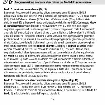
Modo 5: funzionamento allarme (Fig. 9)I parametri fondamentali di questo tipo di funzionamento sono il Set point (St1), il differenziale dell’azione Reverse (P1), il differenziale dell’azione Direct (P2), la zona neutra(P3), il Set dell’allarme di bassa (P25), il Set dell’allarme di alta (P26), il differenziale dell’allarme (P27) e il tempo di ritardo dell’attuazione dell’allarme (P28). Con questo Mododi Funzionamento viene dedicato 1 relè (versioni V e W) o 2 relè (versione Z) per segnalare la presenza di un allarme generico (sonda scollegata o in corto, funzionamentoanomalo dell’elettronica) o un allarme di alta o bassa. Nel caso delle versioni V e W il relèattivato è unico. Nel caso della versione Z viene attivato il relè 3 per gli allarmi generici eper l’allarme di bassa, mentre il relè 4 viene attivato per gli allarmi generici e per l’allarmedi alta. L’attivazione del relè di allarme si somma alle usuali segnalazioni attive con gli altrimodi di funzionamento ovvero codice di allarme sul display e segnale acustico (nelle versioni provviste di buzzer). Nel caso delle versioni W e Z, i relè non utilizzati per la segnalazione degli allarmi possono essere utilizzati con modalità analoghe a quelle vistenel Modo 3. L’uscita di allarme, una volta attivata per un allarme di alta o bassa, ritornanello stato OFF quando la causa di allarme cessa (funzionamento a “riarmo automatico”,ottenuto selezionando un valore “basso” per il differenziale di allarme P27) oppure quandoviene premuto il tasto MUTE (funzionamento con riarmo manuale ottenuto selezionandovalori alti per P27). Da evidenziare che, se si preme il tasto MUTE quando la causa di allarme è ancora persistente, viene tacitata la sirena ma il codice ed il relè di allarme resteranno attivi finchè la causa sarà attiva.
Modo 6: commutazione direct / reverse da ingresso digitale (Fig. 10)I parametri fondamentali di questo tipo di funzionamento sono il Set point (St1), il differenziale (P1) dell’azione Direct, il Set Point (St2) ed il differenziale (P2) dell’azioneReverse. Lo strumento commuta dal funzionamento Direct a quello Reverse (vedi Modo 1 eModo 2) in funzione dello stato dell’ingresso digitale 1.
Programmazione avanzata: descrizione dei Modi di Funzionamento
+05-3015 • rel.3.0 interno ok 18-09-2002 14:31 Pagina 16

Più precisamente si ha: funzionamento Direct quando l’ingresso digitale è aperto, funzionamento Reverse quando è chiuso.
Modo 7: funzionamento Direct con commutazione di Set e differenziale da ingressodigitale (Fig. 11)Con questo Modo la variazione di stato dell’ingresso digitale 1 (aperto/chiuso) non cambiail tipo di azione (sempre Direct) ma cambia il Set Point ed il Differenziale. I parametri fondamentali di questo tipo di funzionamento sono il Set (St1) e il differenziale (P1) attiviquando l’ingresso digitale è aperto ed il Set (St2) e il differenziale (P2) attivi quando l’ingresso digitale è chiuso.
Modo 8: funzionamento Reverse con commutazione di Set e differenziale da ingressodigitale (Fig. 12)Con questo Modo di Funzionamento la variazione di stato dell’ingresso digitale 1 (aperto/chiuso) non cambia il tipo di azione (sempre Reverse) ma cambia il Set ed ilDifferenziale. I parametri fondamentali di questo tipo di funzionamento sono il Set (St1) e ildifferenziale (P1) attivi quando l’ingresso digitale è aperto ed il Set (St2) e il differenziale(P2) attivi quando l’ingresso digitale è chiuso.
Modo 9: funzionamento con 2 Set Point, uno in Direct e uno in Reverse (Fig. 13)I parametri fondamentali di questo tipo di funzionamento sono il Set Point (St1), il differenziale (P1) dell’azione Reverse, il Set Point (St2) ed il differenziale (P2) dell’azioneDirect. Questo Modo di Funzionamento è operativo solo nelle versioni W e Z. È un Mododi Funzionamento simile al Modo 3 (funzionamento con zona neutra) in quanto metà uscite sono attive in Direct e metà in Reverse. La diversità è che non esiste nessun vincolonel posizionamento dei Set point delle due azioni per cui si può operare come se si avessero due strumenti indipendenti che lavorano con la stessa sonda.
17
Programmazione avanzata: descrizione dei Modi di Funzionamento
+05-3015 • rel.3.0 interno ok 18-09-2002 14:31 Pagina 17
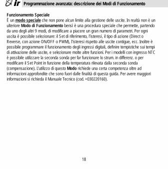
Funzionamento SpecialeÈ un modo speciale che non pone alcun limite alla gestione delle uscite. In realtà non è unulteriore Modo di Funzionamento bensì è una procedura speciale che permette, partendoda uno degli altri 9 modi, di modificare a piacere un gran numero di parametri. Per ogniuscita è possibile selezionare: il Set di riferimento, l’isteresi, il tipo di azione (Direct oReverse, con azione ON/OFF o PWM), l’isteresi rispetto alle uscite contigue, ecc. Inoltre èpossibile programmare il funzionamento degli ingressi digitali, definire tempistiche sui tempidi attivazione delle uscite, e selezionare molte altre funzioni. Per i modelli con ingresso NTCè possibile utilizzare la seconda sonda per far funzionare lo strum. in differenz. o per modificare il Set Point in funzione della temperatura rilevata dalla seconda sonda (compensazione). L’utilizzo di questo Modo richiede una certa competenza oltre ad informazioni approfondite che sono fuori dalle finalità di questa guida. Per avere maggioriinformazioni si richieda il Manuale Tecnico (cod. +030220160).
18
Programmazione avanzata: descrizione dei Modi di Funzionamento
+05-3015 • rel.3.0 interno ok 18-09-2002 14:31 Pagina 18

Modifica automatica dei parametri al variare del Modo di FunzionamentoAd ogni Modo di Funzionamento corrisponde un insieme predefinito di valori per i SetPoints e i principali parametri. Questo significa che quando si modifica il Modo diFunzionamento lo strumento carica automaticamente in memoria l’insieme di valori associati al Modo scelto (vedi tabella successiva). I valori associati al Modo 2 sono in evidenza perché sono i valori di fabbrica o valori di Default. Questi possono essere ripristinati automaticamente spegnendo lo strumento e poi riaccendendolo con il tasto ‘6’premuto (Reset del controllo, vedi pag. 26).
19
Programmazione avanzata: valori di default dei parametri
Par. Descriz. Modo Modo Modo Modo Modo Modo Modo Modo Modo1 2 3 4 5 6 7 8 9
St1 Set Point 20 20 20 20 20 20 20 20 20
St2 Set Point 2 assente assente assente assente assente 40 40 40 40
P1 Differenziale 2.0 2.0 2.0 2.0 2.0 2.0 2.0 2.0 2.0
P2 Differenziale assente assente 2.0 2.0 2.0 2.0 2.0 2.0 2.0
P3 Zona neutra assente assente 2.0 2.0 2.0 assente assente assente assente
P14 Cal.sonda 0.0 0.0 0.0 0.0 0.0 0.0 0.0 0.0 0.0
P25 All. bassa (1) 100 -100 -100 -100 -100 -100 -100 -100 -100
P26 All. alta (2) 999 999 999 999 999 999 999 999 999
P27 Diff. allarme 2 2 2 2 2 2 2 2 2
P28 Ritardo all. (3) 60 60 60 60 60 60 60 60 60
(1): -50 per ingresso NTC(2): 90 per ingresso NTC, +600 per ingresso Pt100.(3): minuti
+05-3015 • rel.3.0 interno ok 18-09-2002 14:31 Pagina 19
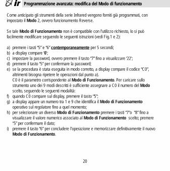
Come anticipato gli strumenti della serie Infrared vengono forniti già programmati, con impostato il Modo 2, ovvero funzionamento Reverse.
Se tale Modo di Funzionamento non è compatibile con l’utilizzo richiesto, lo si può facilmente modificare seguendo le seguenti istruzioni (vedi Fig.1 e 2):
a) premere i tasti “5” e “6” contemporaneamente per 5 secondi;b) a display compare ‘0’;c) impostare la password, ovvero premere il tasto “7” fino a visualizzare ‘22’;d) premere il tasto “5” per confermare la password;e) se la procedura è stata eseguita in modo corretto, a display compare il codice “C0”,
altrimenti bisogna ripetere le operazioni dal punto a).C0 è il parametro corrispondente al Modo di Funzionamento. Per caricare sullo strumento uno dei 9 modi descritti è sufficiente assegnare a C0 il numero del Modoscelto, seguendo le seguenti modalità:
f) quando C0 compare sul display, premere il tasto “5”;g) a display appare un numero tra 1 e 9 che identifica il Modo di Funzionamento
operativo sul regolatore fino a quel momento;h) per selezionare un diverso Modo di Funzionamento premere i tasti “7”o “8” fino a
visualizzare il valore numerico associato al Modo di Funzionamento scelto; premere “5” per confermare il dato;
i) premere il tasto “6” per concludere l’operazione e memorizzare definitivamente il nuovo Modo di Funzionamento.
20
Programmazione avanzata: modifica del Modo di funzionamento
+05-3015 • rel.3.0 interno ok 18-09-2002 14:31 Pagina 20
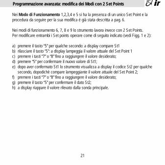
Nei Modo di Funzionamento 1,2,3,4 e 5 si ha la presenza di un unico Set Point e la procedura da seguire per la sua modifica é già stata descritta a pag. 6.
Nei modi di funzionamento 6, 7, 8 e 9 lo strumento lavora invece con 2 Set Points.Per modificare entrambi i Set points operare come di seguito indicato (vedi Figg. 1 e 2):
a) premere il tasto “5” per qualche secondo: a display compare St1b) rilasciare il tasto “5”: a display lampeggia il valore attuale del Set Point 1c) premere i tasti “7” o “8” fino a raggiungere il valore desiderato;d) premere “5” per confermare il nuovo valore di St1;e) dopo aver confermato St1 lo strumento visualizza a display il codice St2 per qualche
secondo, dopodichè compare lampeggiante il valore attuale del Set Point 2;f) premere i tasti “7” o “8” fino a raggiungere il valore desiderato;g) premere il tasto “5” per confermare il dato St2;h) a display riappare il valore rilevato dalla sonda principale.
21
Programmazione avanzata: modifica dei Modi con 2 Set Points
+05-3015 • rel.3.0 interno ok 18-09-2002 14:31 Pagina 21

22
Le possibilità della serie Infrared Universale non si esauriscono con le funzionalità descrittenel capitolo “Programmazione Avanzata”. Ci sono altri parametri speciali (tipo Cxx) che permettono di ottenere prestazioni ancora superiori a quelle sin qui viste. Per utilizzare inmodo corretto queste funzioni é però necessaria una certa competenza e soprattutto la lettura attenta del Manuale Tecnico della Serie Infrared Universale da richiedere alla Carel oal suo distributore.Per comodità si riporta di seguito la lista completa di tutti i parametri disponibili sulla serieInfrared (tipo Pxx e Cxx), esclusi quelli relativi al Modo Speciale (vedi pag. 20); il commentoai parametri è limitato all’essenziale visto che lo scopo dichiarato è fornire una comoda tab.riassuntiva a chi già conosce significato e modalità di funzionamento dei parametri riportati.Per accedere alla lista completa dei parametri seguire la procedura indicata a pag. 20, utilizzando come password il numero ‘77’. Se la procedura é stata eseguita correttamentea display comparirà il primo parametro della lista, ovvero C0.Per la visualizzazione del valore dei parametri e la sua eventuale modifica seguire le modalità già viste in precedenza. Analogamente per confermare le modifiche fatte, sarànecessario terminare la procedura premendo il tasto “6”.
Par. Descrizione Min. Max DefaultSt1 Set Point 1 min. sonda max. sonda 20St2 Set Point 2 (Modi di Funzionam. 6,7,8,9) min. sonda max. sonda 40C0 Modo di Funzionamento (vedi pag. 12) 1 9 2
Selezione dei Differenziali (vedi pagg. 7 e 12)P1 Differenziale Set Point 1 0.1 99.9 2.0P2 Differenziale Set Point 2 (Modi 3,4,5,7,8,9) 0.1 99.9 2.0P3 Differenziale zona neutra (Modi 3, 4, 5) 0.0 99.9 2.0
Per i più esperti: lista completa dei parametri
+05-3015 • rel.3.0 interno ok 18-09-2002 14:31 Pagina 22

Par. Descrizione Min. Max DefaultC4 Autorità. Attiva solo nei modelli NTC, con Modo 1 o 2 -2.0 2.0 0.5
e C19 = 2, 3 o 4. Posto D=NTC2 - SET2, si ha:se C19= 2 per D<=0 SET1=SET1
per D>0 SET1=SET1+D*C4se C19= 3 per D>=0 SET1=SET1
per D<0 SET1=SET1+D*C4se C19= 4 per NTC2 > SET2+P2, SET1=SET1+(D-P2)*C4
per NTC2 < SET2- P2, SET1=SET1+(D+P2)*C4C5 Tipo di regolaz.: 0=Proporzionale, 1= P+I 0 1 0
Parametri relativi alle usciteC6 Ritardo tra gli inserimenti di 2 relè diversi 0 999’’ 5’’C7 Tempo minimo tra le accensioni dello stesso relè 0 15’ 0C8 Tempo minimo di spegnimenti dello stesso relè 0 15’ 0C9 Tempo minimo di accensione dello stesso relè 0 15’ 0C10 Stato relé in caso di allarme sonda: 0 3 0
0= tutti i relè spenti1= tutti i relè accesi2= Accesi i relè in Direct, spenti gli altri3= Accesi i relè in Reverse, spenti gli altri
C11 Rotazione uscite (solo Modi 1, 2, 6, 7 e 8) 0 7 00 = rotazione non attiva1 = rotazione standard2 = rotazione 2+2 (compressori su relé 1 e 3)3 = rotazione 2+2 per valvole norm.aperte4÷7= vedere il manuale tecnico
23
Per i più esperti: lista completa dei parametri
+05-3015 • rel.3.0 interno ok 18-09-2002 14:31 Pagina 23

Par. Descrizione Min. Max DefaultC12 Tempo di ciclo funzionamento PWM 0,2’’ 999’’ 20’’
Parametri sonda (vedi anche pag. 9)C13 Tipo sonda: 0=4-20, 1=0-20; 0=tc K, 1=tc J 0 1 0
NTC: se C13=1 viene visualizzato NTC2 con regolazione su NTC1
P14 Calibrazione sonda o Offset -99 +99.9 0.0C15 Valore minimo per ingresso I e V -99 C16 0.0C16 Valore massimo per ingresso I e V C15 999 100C17 Velocità risposta sonda (filtro antidisturbi) 1 14 5C18 Selezione unità temperatura: 0=°C, 1=°F 0 1 0C19 Funz. 2° sonda: solo vers.NTC, Modo 1 o 2 0 4 0
0 = nessuna modifica al funz. Standard1 = funzionamento differenziale NTC1 - NTC22 = compensazione estiva3 = compensazione invernale4 = compensazione sempre attiva con zona morta
Parametri SetC21 Valore minimo Set Point 1 -99 C22 min.sondaC22 Valore massimo Set Point 1 C21 999 max.sonda C23 Valore minimo Set Point 2 -99 C24 min.sondaC24 Valore massimo Set Point 2 C23 999 max.sonda
24
Per i più esperti: lista completa dei parametri
+05-3015 • rel.3.0 interno ok 18-09-2002 14:31 Pagina 24

Par. Descrizione Min. Max DefaultParametri di allarme (vedi anche pagg. 9 e 10)P25 Set allarme di bassa (assoluto) -99 P26 min.sondaP26 Set allarme di alta (assoluto) P25 999 max.sondaP27 Differenziale allarme 0.1 99.0 2.0P28 Tempo ritardo attuazione allarme 0 120’ 60’C29 Ingresso dig.1 (attivo se C0 è diverso da 6, 7 e 8) 0 4 0
In caso di allarme, lo stato dei Relè dipende da C310= ingresso non attivo1= allarme esterno immediato, reset automatico2= allarme esterno immediato, reset manuale3= allarme esterno con ritardo (P28), reset manuale4= ON/OFF regolazione in relazione stato ingr.dig.
C30 Gestione ingresso digitale 2 (solo IRDR) 0 4 0Per le opzioni vedi C29
C31 Stato uscite in caso di allarme da ingresso digitale: 0 3 0stesse opzioni del parametro C10
Altre predisposizioniC32 Indirizzo per connessione seriale 1 16 1C33 Non modificare questo Parametro 0 1 0C50 abilitazione tastiera (TS) e telecomando (TC) 0 4 4
0= TS off, TC on (solo parametri Tipo P) (Def.=1 per1= TS on, TC on (solo parametri Tipo P) strumenti2= TS off, TC off con serial3= TS on, TC off number4= TS on, TC on (tutti i parametri) <10.000)
C51 Codice per l’abilitazione del telecomando 0 120 0
25
Per i più esperti: lista completa dei parametri
+05-3015 • rel.3.0 interno ok 18-09-2002 14:31 Pagina 25

26
- Problema: la tastiera e/o il telecomando non funzionanoVerifica: si veda parametro C50.
- Problema: la misura oscilla continuamenteVerifica: - la misura può essere influenzata da disturbi elettromagnetici. Si
veda il Paragrafo “ Consigli per un’installazione ottimale”- modificare il parametro C17 inserendo un valore minore.
- Problema: gli allarmi di alta e/o bassa non sono segnalatiVerifica: il ritardo allarme può essere eccessivo. Vedi param. P25, P26 e P27
- Problema: le uscite non vengono attivateVerifica: verificare le tempistiche di protezione delle uscite, par. C6, C7, C8.
- Problema: le uscite vengono attivate troppo frequentementeVerifica: il differenziale è troppo stretto. Aumentarlo e/o modificare le tempistiche di
protezione sulle uscite, parametri C6, C7 e C8.- Problema: la misura non raggiunge mai il valore di Set Point
Verifica: escludendo problemi di dimensionamento dell’impianto, il differenziale, P1 o P2, è troppo largo o la zona neutra P3 è eccessiva
- Problema: la misura visualizzata a display non corrisponde al valore realeVerifica: Può essere un problema di installazione del sensore (vedi pag. 7).
Nelle versioni con ingresso in corrente, in tensione o J/K Tc si veda il paragrafo “Parametri speciali per termocoppie, ...” a pag. 12.
Reset del controlloAvvertenza: può essere utile riportare lo strumento alla configurazione di fabbrica. Ciò può essere fatto con la seguente procedura di Reset:1 - togliere tensione allo strumento2 - ridare tensione tenendo premuto il tasto ‘6’
Analisi guasti e Reset del controllo
+05-3015 • rel.3.0 interno ok 18-09-2002 14:31 Pagina 26

27
Messaggio Descrizione Causa Verifiche / RimediEr0 errore sonda cavo sonda interrotto verifica dei collegamenti
o in corto circuito tra strumento e sondaerrore collegamento verifica del segnale sondasonda guasta (es.: NTC=10KΩ@ 25°C)
Er1(solo errore sonda come sopra, ma come sopra, mavers.NTC) NTC2 per sonda NTC2 per sonda NTC2Er2 errore caduta di tensione ripristinare i valori di fabbrica:
memoria durante la spegnere lo strumento e quindiprogrammazione accendenderlo con ‘6’ premuto.interferenze elettriche Se Er2 persiste sostituire lo strum
Er3 allarme é aperto il contatto funzionamento specialeesterno collegato (vedi param. C29 a pag. 24)attivo all’ingresso digitale verificare contatto esterno
Er4 allarme di l’ingresso ha superato verifica dei parametriALTA P26 per un tempo>P28 P26, P28
Er5 allarme di l’ingresso é sceso sotto verifica dei parametriBASSA P25 per un tempo >P28 P25, 28
Note importanti:- In caso di allarme, il buzzer e l’indicazione sul display devono essere resettati
manualmente premendo il tasto ‘6’ (vedi fig. 1 e 2). Per il codice di allarme il reset è attivo solo se la causa di allarme è scomparsa. Il relé di allarme (Modo 5) ha reset automatico, tranne che per valori particolari di P27 (Er4 e Er5) e C29 (Er3). Si veda il Manuale Tecnico.
- Per Er0, Er1 e Er2 il ripristino del funzionamento del regolatore è automatico al cessare della causa di allarme; Er4 e Er5 non influenzano il funzionamento.
- Per Er3 il ripristino del funzionamento può essere manuale o automatico (vedi C29).
Condizioni di Allarme, Cause e Rimedi
+05-3015 • rel.3.0 interno ok 18-09-2002 14:31 Pagina 27
28
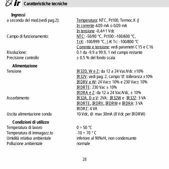
Ingressia seconda del mod.(vedi pag.2): Temperatura: NTC, Pt100, Termoc.K /J
In corrente 4/20 mA o 0/20 mAIn tensione -0,4/+1 Vdc
Campo di funzionamento: NTC: -50/90 °C, Pt100: -100/600 °C, TcK: -100/999 °C, J/K Tc: -100/800 °CCorrente e tensione: vedi parametri C15 e C16
Risoluzione: 0.1 da -9.9 a 99.9, 1 nel campo restantePrecisione controllo ± 0.5 % del fondo scala
AlimentazioneTensione IR32D, W e Z: da 12 a 24 Vac/Vdc ±10%
IR32V: vedi pag. 2, campo ‘d’: tolleranza ±10%IRDRV e W: 24 Vac± 10% e 230 Vac± 10%IRDRTE: 230 Vac ± 10%IRDRA e Z: da 12 a 24 Vac/Vdc, ± 10%
Assorbimento IR32A, D e V: 2VA; IR32W e IR32Z: 3 VAIRDRTE, IRDRV, IRDRW e IRDRA: 3 VAIRDRZ: 4 VA
Uscita alimentazione sonda 10 Vdc, @ max 30mA (8 Vdc per IRDRW)
Condizioni di utilizzoTemperatura di lavoro 0 ÷ 50 °CTemperatura di immagazz.to -10 ÷ 70 ° CUmidità relativa ambientale inferiore al 90%rH, non condensantePolluzione ambientale normale
Caratteristiche tecniche
+05-3015 • rel.3.0 interno ok 18-09-2002 14:31 Pagina 28

IsolamentiLe parti in bassa tensione presentano un isolamento principale rispetto alle parti in bassissima tensione e un doppio isolamento rispetto al frontale.
UsciteNumero relè(a seconda del mod.) IR32 per NTC: 1, 2 o 4 relè SPDT
altri IR32V: 1 relè SPSTIR32W: 1 relè SPST + 1 SPDTIR32Z: 1 relè SPST + 3 SPDTIRDRTE, IRDRV e W: 1o 2 relè SPDTIRDRZ: 1° e 2° relè SPDT, 3° e 4° relè SPST IR32D: 1 uscita per SSR (relè stato solido);IR32A e IRDRA: 4 uscite per SSR (relè stato solido)
Caratteristiche relè (tutti i mod.) max. tensione 250 Vac, max. potenza 2000 VA, max. corrente spunto 10A. Disconnessione di tipo 1C secondo norme ECC EN 60730-1
Caratteristiche segnale per SSR tensione uscita: 10 Vdc; resistenza uscita: 660 Ω(relè stato solido) max. corrente uscita: 15 mA
Caratteristiche meccanicheConnessioni strumento IR32: montaggio a pannello con staffa
IRDR: montaggio su guida DINContenitori plastici, autoestinguenza IR32 secondo UL94 - VOGrado di protezione IR32: IP 65 con strum. montato a pannello
IRDR: IP 40 con strum.montato a quadroCollegamenti tramite morsetti a vite sez.max.1.5 mm2
29
Caratteristiche tecniche
+05-3015 • rel.3.0 interno ok 18-09-2002 14:31 Pagina 29

Collegamento seriale IR32: tramite accessorio IR32SER (modelli indicati a pag.1) IRDR: tramite accessorio IRDRSER
Modifica parametri da tastiera, da seriale e da telecomando (per l’accessorio telecomando vedi listino)
Nota importante: i cavi usati devono resistere alla massima temperatura d’esercizio,ovvero alla massima temperatura ambiente prevista + l’autoriscaldamento del controllo pari a 20 °C con le uscite tutte alla max.portata.
30
Caratteristiche tecniche
+05-3015 • rel.3.0 interno ok 18-09-2002 14:31 Pagina 30

La serie Universale Infrared Carel ha funzionalità sofisticate e caratteristiche innovative,assolutamente superiori ad altri strumenti simili proposti dai concorrenti in questa classe diprezzo. Ma non è tutto!Carel propone per la serie Infrared una gamma di accessori in grado di permettere prestazioni ancora superiori. In particolare ricordiamo:
- Telecomando per la programmazione dei parametri di funzionamentoIl telecomando Carel per la serie Universale é disponibile nelle principali lingue. Con questoaccessorio modificare i parametri di funzionamento è semplice come cambiare il volume delvostro televisore! Contattate il vostro distributore per maggiori informazioni.
- Kit Modì per la modifica dei parametri di funzionamento da PCIl kit Modì per Personal Computer é la soluzione ideale per produzioni in piccola/mediaserie. Permette infatti di memorizzare su files eventuali configurazioni ‘standard’ che possono essere semplicemente e velocemente trasferite agli strumenti tramite un collegamento seriale. In questo modo si evita ogni possibile errore legato alla programmazione manuale dei controlli da parte di personale non esperto.
- Collegamento serialeTutti i controlli sono predisposti al collegamento in rete per la realizzazione di sistemi di supervisione e teleassistenza.
31
Sistemi avanzati di programmazione e supervisione
+05-3015 • rel.3.0 interno ok 18-09-2002 14:31 Pagina 31

- Sistema di supervisione e teleassistenzaCarel ha una vasta gamma di programmi software che consentono di risolvere ogni problema di supervisione e teleassistenza.Tra le principali prestazioni:
• monitoraggio di tutte le variabili con memorizzazione dei dati su hard-disk. È possibile visualizzare l’andamento degli ingressi con grafici su base oraria, giornaliera o mensile.I dati memorizzati ed i grafici possono essere stampati.
• rilevazione e registrazione di eventuali allarmi, con data e ora• modifica dei principali parametri direttamente da PC.
32
Sistemi avanzati di programmazione e supervisione
+05-3015 • rel.3.0 interno ok 18-09-2002 14:31 Pagina 32

Introduction to the IR Series . . . . 34Key features . . . . . 35How to install the regulator . . . . 36Hints for optimum installation . . . . 37Easy set-up:
basic concepts . . . . . 39factory-set functions . . . . 40parameters descriptions . . . . 41Set-point and useful parameter modifications . . 42
Special parameters for thermocouples, tension and current probes . 43Advanced set-up:
basic description and concepts . . . 44Function Modes description . . . . 45parameters default values . . . . 49Function Mode modification . . . . 50Function Mode modification with 2 Set Points . . 51
List of the parameters . . . . . 52Troubleshooting and Reset of the control. . . . 57Troubleshooting . . . . . 58 Technical specifications . . . . 59Advanced programming tools and Supervisory systems . . 62Function Mode Diagrams . . . . 63Connections . . . . . . 67Dimensions . . . . . 78
33
Contents
+05-3015 • rel.3.0 interno ok 18-09-2002 14:31 Pagina 33
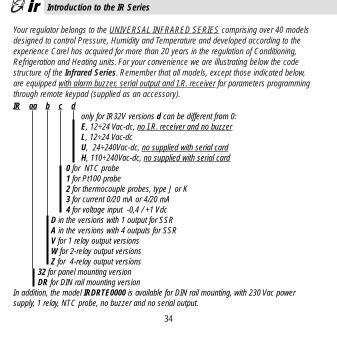
Your regulator belongs to the UNIVERSAL INFRARED SERIES comprising over 40 modelsdesigned to control Pressure, Humidity and Temperature and developed according to the experience Carel has acquired for more than 20 years in the regulation of Conditioning,Refrigeration and Heating units. For your convenience we are illustrating below the code structure of the Infrared Series. Remember that all models, except those indicated below, are equipped with alarm buzzer, serial output and I.R. receiver for parameters programmingthrough remote keypad (supplied as an accessory).
34
Introduction to the IR Series
IR aa b c donly for IR32V versions d can be different from 0:E, 12÷24 Vac-dc, no I.R. receiver and no buzzerL, 12÷24 Vac-dcU, 24÷240Vac-dc, no supplied with serial cardH, 110÷240Vac-dc, no supplied with serial card
0 for NTC probe1 for Pt100 probe2 for thermocouple probes, type J or K3 for current 0/20 mA or 4/20 mA4 for voltage input -0,4 / +1 Vdc
D in the versions with 1 output for SSRA in the versions with 4 outputs for SSRV for 1 relay output versionsW for 2-relay output versionsZ for 4-relay output versions
32 for panel mounting versionDR for DIN rail mounting version
In addition, the model IRDRTE0000 is available for DIN rail mounting, with 230 Vac power supply, 1 relay, NTC probe, no buzzer and no serial output.
+05-3015 • rel.3.0 interno ok 18-09-2002 14:31 Pagina 34

35
Refer to picture 1 for IR32 models and to picture 2 for IRDR:
1 - Display: shows the value measured by the connected probe. In the event of alarm condition the probe value will be shown alternately with the codes of activated alarms. During programming it shows the parameter codes and their values.
2 - Decimal Point: shows the number of decimal points in the controlled parameter.3 - Led reverse: flashes when at least one device with “Reverse” function is activated.
The number of flashes indicates the Reverse activated relays.A 2-second-pause occurs, between flashes.
4 - Led direct: flashes when at least one device with “Direct” function is activated.The other indications are the same as in “ Led reverse” .Note: for the meaning of Reverse and Direct see next paragraph.
5 - Key SEL: displays and/or selects the Set-point. If pressed for more than 5 seconds together with PRG-MUTE, it allows you to enter the password and the configuration parameters (code type ‘Cxx’).
6 - Key PRG/Mute: If pressed for 5 seconds it allows you to access the menu of the more frequently used parameters (code type ‘Pxx’). In the event of alarm condition, it silences the buzzer and it also resets any other alarm signal, if pressed after the event that caused the alarm has disappeared.
7 - Key Up: increases the value of the Set-point or of any other selected parameter.
8 - Key Down: decreases the value of the Set-point or of any other selected parameter. For NTC input versions, if pressed when the main probe value is shown, it displays the value of the second probe as long as the key is being pressed (see NTC1, NTC2, paragraph “Connections”).
Key features
+05-3015 • rel.3.0 interno ok 18-09-2002 14:31 Pagina 35

To install the regulator follow these instructions:
1) connect probes and power supply following the instructions in the paragraphs below “Hints for Installation” and “Connections”. It is advisable to connect actuators only after having programmed the controller.
2) setting the instrument. The Infrared Series regulators are supplied preprogrammed so as to be used in the more frequent applications (see page 38). However, it is always possible to modify in part or completely the factory-set function so as to customize the instrument to your requirements. There are two programming procedures:2a) simplified programming. In all factory-set applications, you only have to check andif necessary to modify a few parameters (Set-point and differential for example). It is alsopossible to modify other parameters to obtain better performance (see “Description of useful Parameters”).2b) advanced programming. It allows the instrument to be tailored to uses different from the factory-set ones. As you will see, programming is extremely simple thanks to a series of prearranged functions (Modes), which are ready to be activated.
3) for models with current, voltage or J thermocouple inputs, some special parameters should be selected. See paragraph “Special parameters for thermocouples and voltage/current probes”.
4) connecting the actuators. It is recommended to carefully evaluate the maximum switching power of relays (see “Technical specifications”).
36
How to install the regulator
+05-3015 • rel.3.0 interno ok 18-09-2002 14:31 Pagina 36

For optimun performance please follow the notes below.
- Remember that it is necessary to install all the electromechanical devices required to ensure a safety operation of the plant.
- Avoid installation in places with the following features:- Relative humidity higher than 90% or condensing- Heavy vibrations or shocks- Exposures to continuous jets of water- Exposure to aggressive and polluting environment (eg: sulphurous and ammoniacal
gases, saline mist, smoke) to avoid corrosion and/or oxidation- High magnetic and/or radio interferences (avoid therefore machine installation near
transmitter aerials)- Exposure of controllers to direct solar radiation and to atmospheric agents in general.
- It should be remembered that incorrect connection of power supply voltage can seriously damage the system. When connecting the regulators it is necessary to
follow these instructions:- Use wire suitable for the used terminals- Slacken each termination screw and insert the wire terminals, then tighten the screws- When the procedure has ended, pull the cables slightly to check the correct tightening- Separate as much as possible the probes and digital input cables from those of
inductive and power loads, to avoid any electromagnetic interferences.
- Never insert in the same channels power cables and probe cables.
37
Hints for optimum installation
+05-3015 • rel.3.0 interno ok 18-09-2002 14:31 Pagina 37

- Avoid installating probe cables near power devices (Magnetothermic contactors or others).
- Probes can be positioned up to a maximum distance of 100 meters from the controller, provided that their cables have a minimum section of 1mm2 and are shielded.
- To improve immunity against noise and to get a better precision, we advise using shielded cables; in this case, connect just one end of the shielding to the electrical panel ground; do not connect the other end of the cable.When usign thermocouples, it is necessary to use shielded cables to ensure protection against noise; moreover, the probes can be lengthened only by using the suitable compensated cables and connectors. (As for codes see Carel price-list).
- If a supervisory network connection is provided through suitable serial boards (IR32SER for IR32 models and IRDRSER for IRDR models), it is necessary to pay attention to the earthing of the system. In particular: the secondary of the transformers which feed the instruments should not be earthed. If it is necessary to connect to a transformer with a earthed secondary, an isolating transformer should be used. Even if it is possible to
connect more instruments to the same insulation transformer, we suggest you to use a different insulation transformer for each instrument (see Carel price list for the codes andspecifications of the insulation transformers).
38
Hints for optimum installation
+05-3015 • rel.3.0 interno ok 18-09-2002 14:31 Pagina 38

Before describing how to program the instrument, it is necessary to review some basic concepts:
- Direct Mode and Reverse Mode: a regulator works in Direct mode, when it tends to operate against the rise of the controlled variable. Direct function is typical, for example, of refrigeration: the more the measured temperature increases the more the capacity of the refrigeration circuit increases, so as to make temperature itself fall. We use the term Reverse if the regulation tends to operate against the decreasing of the controlled variable. This is used, for example, in heating systems where you have to oppose the decreasing temperature by increasing the heat production.
- Set-point (or Set): this is the value that the controlled parameter has to maintain, for example the value of the temperature at which an oven is to work. When the controlled parameter is at the Set-point value, all outputs are de-activated.
- Differential or hysteresis: regulates the outputs when the controlled parameter deviates from the Set. Without Differential the instrument could pass suddenly from all outputs OFF (parameter equal to SET) to all outputs ON (parameter different from SET).Instead, when differential > 0, the outputs insertion is gradual and the regulator will activate all outputs only when the difference between the controlled parameter and the Set Point exceeds the value of the Differential. A ‘narrow’ differential usually maintains thecontrolled parameter very near to the Set, but it can provoke frequent turning ON and OFF of the controlled devices i.e. hunting problems. If a very precise regulation is required, instead of selecting a narrow differential, the P+I regulation (described in the “Technial Manual”) can be activated.
39
Easy set-up: basic concepts
+05-3015 • rel.3.0 interno ok 18-09-2002 14:31 Pagina 39

The instrument is supplied ready for the following applications:
Models with temperature probes (NTC, Pt100,Thermocouples): control of ovens, burners, heating systems and in general low temperature alarms.
Models for humidity probes: control of humidifiers and in general low humidity alarms.
Models for pressure probes: control of evaporators and in general low pressure alarms.
As shown in the picture, the main parameters in this function mode are Set Point (St1) and differential (P1). For the standard function, which corresponds to Reverse action, the regulator energizes the outputs only if the controlled parameter decreases from the Set-point value. Once fixed at the desired Set Point (St1), the outputs will be energized oneby one as the parameter deviates from St1. As shown in the picture, in models with moreoutputs, the activation of relays is equally distributed within the differential. When the controlled parameter is equal to/lower than St1-P1, all outputs will energize. Viceversa, starting from values lower than St1, if the parameter starts to increase any active relay willbe de-activated as approaching St1. When the St1 value is reached, all outputs will be disenergized.The REVERSE led will flash with a number of pulses equal to the activated outputs.
40
Easy set-up: factory -set functioning
mod. Z mod. V mod. W
RR RRRR
OUT 4 OUT 3 OUT 2 OUT 1
Diff.(P1)
Set (St 1)
Diff.(P1)
Set (St 1)
OUT 2 OUT 1OUT 1
R
Diff.(P1)
Set (St 1)
Fig. 4
+05-3015 • rel.3.0 interno ok 18-09-2002 14:31 Pagina 40

To customize the regulator’s function to your requirements it will be necessary to modify theSet (factory-set value= 20) and the differential (factory-set value= 2). However, there areother parameters, not previously programmed, which can be usefully selected:
Useful Parameters
Higher/Lower limit alarm set: allows you to select a maximum and a minimum value forthe controlled param. When the instrument detects a value which is beyond the set thresholds,it displays an alarm code and gives off an acoustic signal (in models with buzzer). High andlow thresholds are absolute values and so, to avoid alarm intervention during normal function,they have to be beyond the “Set Point-differential” plus “Set Point”. If the Set Point has beenmodified, it is necessary to check that the new combined values do not exceed alarm limits.
Alarm differential: the hysteresis of the alarms. A minimum differential is necessary toavoid consecutive activating/deactivating of alarms due to small variations in the controlled parameter. Infrared Series regulators have a factory-set alarm differential value of “2”.Higher/lower limit alarms have an automatic reset, in fact when the controlled parameterreturns within the maximum allowed limits, the alarm is automatically deactivated.It is possible to set the alarm set, even if a relative alarm, assigning the values with anegative sign to the parameter P27). In this case, pay attention to the signs of P25 andP26: as a matter of fact the negative sign shows the event of its respective alarm before thePoint, whereas the positive sign shows the event after the Set Point.
Alarm delay: allows you to set a time-delay in the alarm signal. The regulator activates thealarm only after the selected time delay has elapsed. If during a delay the controlled parameter returns within the allowed limits, the timer will be zeroed.
Calibration offset: allows you to modify the value displayed by the instrument. This compensates for any errors or differences with other instruments.
41
Easy set-up: parameters descriptions
+05-3015 • rel.3.0 interno ok 18-09-2002 14:31 Pagina 41

42
For your convenience we have listed the factory-set values of the Set Point and of the otheruseful parameters as follows.
Parameter Code Factory-set value RangeSet Point St1 20 probe limitsDifferential P1 2,0 0.1 / 99.9Calibration offset P14 0,0 -99 / 99Lower limit alarm P25 depending on the probe -99 / P26Higher limit alarm P26 depending on the probe P25 / 999Alarm Differential P27 2,0 0.1 / 99.9Alarm Delay P28 60 minutes 0 / 120 min.
The Set-point can be modified as follows (pictures 1 and 2):a) press the “5” key for some seconds: the display shows St1;b) release the “5” key: the actual value of the Set-point will flash;c) press either “7” or “8” keys until you reach the desired value;d) press “5” to confirm the new St1 value;
The Differential and the Useful Parameters can be modified as follows:a) press the “6” key for 5 seconds: “P1” is displayed;b) press either “7” or ”8” keys until the parameter to be modified is shown;c) press the “5” key: the present value of the parameter to be modified is displayed;d) press either “7” or “8” keys until you reach the desired value;e) press “5” to confirm;f) the code identifying the modified parameter is displayed;g) repeat instructions from point b) to point f) if you want to modify other parameters,
otherwise go to point h);h) press the “6” key to store the modified data and go back to normal operation.
Easy set-up: set point and useful parameters modification
+05-3015 • rel.3.0 interno ok 18-09-2002 14:31 Pagina 42

Current input models have a special parameter, C13, which allows you to choose the typeof current input: C13=0 for 4/20 mA probes, factory-set value, and C13=1 for 0/20 mA probes. The value is therefore to be modified only if a 0/20 mA probe is being used.The same C13 parameter is used by thermocouple input instruments: The value C13=0, factory-set, corresponds to thermocouples type K, C13=1 to thermocouples type J. Thevalue of C13 is therefore to be modified only if you require thermocouples type J.Current/voltage inputs instruments have two special parameters, C15 and C16, which allowthe user to define the working range of the actual probe, and which are the values corresponding to minimum (C15 parameter) and maximum (C16 parameter) input. C15and/or C16 parameters must be modified only if the probe limits are different from the factory-set ones: C15=0 and C16=100.
C13, C15 and C16 parameters can be modified as follows:a) press the “5” and “6” keys simultaneously for 5 seconds;b) the display shows 0;c) select the password, by pressing the “7” key until 22 is displayed;d) press the “5” key to confirm the password;e) if the selected password is correct, code “C0” will be displayed, otherwise you will have
to repeat procedures from point a);f) press the “7” and/or “8” keys until the desired parameter is displayed (C13, C15 or C16):
then press the “5” key;g) the value associated to the parameter is displayed: press either “7” or “8” keys until the
desired value is displayed; press “5” to confirm;h) repeat procedures from point f) to modify other parameters or press the “6” key to exit
the procedure.
43
Special parameters for thermocouples, tension and current probes
+05-3015 • rel.3.0 interno ok 18-09-2002 14:31 Pagina 43

Advanced programming allows you to modify the functions of the instrument to adapt it touses different from the factory-set ones (pag. 38).This is an extremely simple procedure thanks to the Function Modes. In each regulator, infact, have been memorized as many as 9 different programs designed to optimally providethe best solution to any control problems. The procedure is as follows:
1) having chosen the Function Mode suitable to your application, you will have to activate itby modifying a parameter (C0)
2) then you will be able to modify Set-point, differential and any other parameter you consider useful by following the same procedures described above.
Before describing in detail the features of the 9 “Function Modes” it is necessary to introduce two other basic concepts:
Multiple Set-Points. We have previously described the function with only one Set. Thereare, however, applications with 2 Sets: this is the case, for example, of a heating systemworking with two different Sets, one for functioning by day and the other by night, or of aconditioning system with a winter Set and a summer Set. As you will see in the descriptionof Modes, the Infrared series regulators can also manage two set-points.
Neutral Zone or Dead Band: indicates an interval in the values around the Set Pointwhere the controlled parameter can fluctuate without having to activate any outputs. Theconcept will be resumed in the description of Modes 3, 4 and 5.
Note: to follow the description of Modes more easily it is advisable to refer to the pictures atthe end of the manual. In the description below, associated to parameters, you will alwaysfind the corresponding programming code (eg. Set will be associated with code St1) so asto simplify any modification of these parameters.
44
Advanced set-up: basic description and concepts
+05-3015 • rel.3.0 interno ok 18-09-2002 14:31 Pagina 44

Mode 1: DIRECT function (pict. 5).The main parameters in this kind of function are Set Point (St1) and differential (P1). In theDirect function mode the regulator opposes the controlled parameter only if it exceeds the Set Point value. Having once fixed the desired Set Point (St1), the outputs will be energizedone by one as the parameter deviates from St1. As shown in the picture, the relays in themodels with more outputs are equally distributed within each single set differential. Whenthe controlled parameter is equal to/higher than St1+P1, all outputs energize. Viceversa, ifthe parameter, starting from values higher than St1, starts to decrease, any active relay willbe deactivated as approaching St1. When the St1 value is reached, all outputs will be disenergized. The DIRECT led will flash periodically, once for each activated output.
Mode 2: REVERSE function mode (pict. 6).This is the previously described factory-set mode.
Mode 3: Dead-Band function mode (pict. 7).The main parameters in this kind of function mode are Set Point (St1), Reverse mode differential (P1), Direct mode differential (P2) and Dead-Band (P3). The aim of the regulatoris to bring the controlled parameter within a limited range, called dead zone, set around the Set Point (St1). As shown in the picture, the dead zone value depends on the P3 parametervalue. Within the dead zone the instrument does not require the intervention of any device.Outside the dead zone the instrument will work in DIRECT mode, when the controlled parameter increases and, in REVERSE mode, when it decreases. According to the usedmodel, there can be one or more relays in Direct and Reverse function. Said outputs are activated/deactivated according to the procedures already shown in modes 1 and 2, according to the values of the controlled parameter, of St1 value, of P1 and of P2. TheDIRECT led and REVERSE led indicators will flash as already described. Warning: whenthe instrument has only one relay output, it will work in REVERSE mode with Dead-Band.
45
Advanced set-up: Function Modes description
+05-3015 • rel.3.0 interno ok 18-09-2002 14:31 Pagina 45

Mode 4: PWM function mode (pict. 8).The main parameters in this kind of function mode are Set Point (St1), Reverse mode differential (P1), Direct mode differential (P2) and dead zone (P3). The logic of regulation inthis kind of function is the same as in Mode 3. It is, in fact, a function with Dead-Band withthe extra feature that relays are activated in an impulsive way according to the PWM procedure (Pulse Width Modulation). In practice, each single relay, instead of being activated when exceeding the differential (or part of it), is periodically activated (with aperiod of 20 seconds, modifiable if needed) for a time from 0,2 to 20 seconds, according tothe amount of power. The relay ON period is proportional to the position of the controlledparameter within the differential, as shown in the picture. The PWM functioning thereforeprovides a proportional control which can improve the regulation of the controlled parameter. However, the limits of this kind of functioning should be considered. For example,it is not advisable to use it with compressors or other actuators whose reliability can sufferthe effects of rapid switching. It should be remembered, then, that too rapid on/off routinesof the relays can compromise their life (calculated in about 1 million activations). In PWMfunction DIRECT/ REVERSE leds will flash with a number of flashes equal to the number ofactive outputs. When the instrument is equipped with only one relay, it will function inREVERSE mode with Dead-Band.
Mode 5: alarm function mode (pict. 9).The main parameters in this kind of function mode are Set Point (St1), Reverse mode differential (P1), Direct mode differential (P2), Dead-Band (P3), lower limit alarm Set (P25),higher limit alarm Set (P26), alarm differential (P27) and alarm time delays (P28). With thiskind of function 1 relay (V and W versions) or 2 relays (Z version) have been set to signalthe presence of a general alarm (disconnected or short circuit probe, anomalous function inelectronics) or a higher/lower limit alarm. In V and W versions the activated relay is always
46
Advanced set-up: Function Modes description
+05-3015 • rel.3.0 interno ok 18-09-2002 14:31 Pagina 46

the same. In Z version relay 3 is activated for general alarms and for lower limit alarm, whereas relay 4 is activated for general alarms and for higher limit alarm. The alarm relayactivation is added to the other alarm signals, active with other function modes that arealarm code on display and acoustic warning (in buzzer equipped versions). In W and Zversions, the relays which are not used for the alarm signal can be used as in Mode 3.Once activated, the alarm output will go back to the OFF position when the cause of thealarm ends (“automatic resetting”, is obtained with a “low” value selected for the alarm differential P27) or when the PRG-MUTE key is being pressed (with manual resetting, isobtained by selecting “high” values for P27). It is important to point out that if the MUTE keyis pressed when the cause of the alarm is still present, the buzzer will be silenced but thealarm code and the alarm relay will remain active.
Mode 6: Direct / Reverse selection from digital input (pict. 10).The main parameters in this kind of function are Set Point (St1), Direct mode differential(P1), Set Point (St2) and Reverse mode differential (P2). The instrument selects Direct orReverse function (see Mode 1 and Mode 2) according to the condition of the digital input 1.More precisely you will have: Direct function when digital input 1 is open and Reverse function when digital input 1 is closed.
Mode 7: Direct function mode with selection of Set and differential from digitalinput (pict. 11).With this kind of function the condition of the digital input (open/closed) does not changethe kind of action (always Direct), but changes Set Point and differential. The main parameters in this kind of function are active Set (St1) and differential (P1) with open digitalinput and active Set (St2) and differential (P2) with closed digital input.
47
Advanced set-up: Function Modes description
+05-3015 • rel.3.0 interno ok 18-09-2002 14:31 Pagina 47
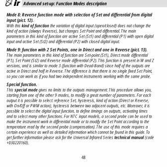
Mode 8: Reverse function mode with selection of Set and differential from digitalinput (pict. 12).With this kind of function the variation of digital input (open/closed) does not change thekind of action (always Reverse), but changes Set Point and differential. The main parameters in this kind of function are active Set (St1) and differential (P1) with open digitalinput and active Set (St2) and differential (P2) with closed digital input.
Mode 9: function with 2 Set Points, one in Direct and one in Reverse (pict. 13).The main parameters in this kind of function are Set-point (St1), Direct mode differential(P1), Set Point (St2) and Reverse mode differential (P2). This function is present in W and Zversions, and is similar to mode 3 (function with Dead-Band) since half of the outputs are active in Direct and half in Reverse. The difference is that there is no single fixed Set Point,so you can work as if you had two independent instruments working with the same probe.
Special function.This special mode gives no limits to the outputs management. This procedure allows you,starting from one of the other 9 modes, to modify a great number of parameters. For each output it is possible to select: reference Set, hysteresis, kind of action (Direct or Reverse,with On/Off or PWM action), hysteresis between two adjacent outputs, etc. Moreover, it ispossible to select the digital input function, to define timings on outputs, activating timesand to select many other functions. For NTC input models, a second probe can be used tomake the instrument work in differential mode or to modify the Set Point according to thetemperature read by the second probe (compensation). The use of this mode requires acertain experience as well as detailed information which cannot be found in this guide. Toget further information please ask for the Universal Infrared Series technical manual (code+030220160).
48
Advanced set-up: Function Modes description
+05-3015 • rel.3.0 interno ok 18-09-2002 14:31 Pagina 48

Value of the main parameters with the different Function Modes.Each Function Mode has a defined set of values for Set-points and main parameters. Thismeans that, when the Function Mode is modified, the instrument will automatically store theset of values associated to the selected Mode.The table below shows the values associated with the first 9 Modes. Mode 2 has been highlighted because it is the factory-set one (Default value). In any moment it is possible toreset the Default value using the ‘Reset procedure’ (see pag. 57).
49
Advanced set-up: Parameters default values
Par. Descript. Mode 1 Mode 2 Mode 3 Mode 4 Mode 5 Mode 6 Mode 7 Mode 8 Mode 9
St1 Set-point 1 20 20 20 20 20 20 20 20 20
St2 Set-point 2 absent absent absent absent absent 40 40 40 40
P1 Hysteresis 2.0 2.0 2.0 2.0 2.0 2.0 2.0 2.0 2.0
P2 Hysteresis absent absent 2.0 2.0 2.0 2.0 2.0 2.0 2.0
P3 Dead-Band absent absent 2.0 2.0 2.0 absent absent absent absent
P14 Probe Calibr. 0.0 0.0 0.0 0.0 0.0 0.0 0.0 0.0 0.0
P25 Lower al. (1) -100 -100 -100 -100 -100 -100 -100 -100 -100
P26 Higher al. (2) 999 999 999 999 999 999 999 999 999
P27 Alarm Hyster. 2 2 2 2 2 2 2 2 2
P28 Alarm del. (3) 60 60 60 60 60 60 60 60 60
(1): -50 NTC input(2): 90 for NTC input, +600 for Pt100 input.(3): minutes
+05-3015 • rel.3.0 interno ok 18-09-2002 14:31 Pagina 49

As previously explained, the Infrared series instruments are supplied ready to use, with pre-selected Mode 2 (Reverse function).
If this kind of function is not compatible with the required use, it can be easily modified by following these instructions (see pict.1 and 2):
a) press the “5” and “6” keys simultaneously for 5 seconds;b) the display shows 0;c) select the password by pressing the “7” key up to 22;d) press the “5” key to confirm the password;e) if the selected password is correct, the display will show the code “C0”, otherwise you
will have to repeat the instructions from point a).C0 is the parameter corresponding to the “Function Mode”. To load one of the 9 describedModes it is sufficient to give C0 the chosen Mode number, according to the following instructions:f) when C0 is displayed, press the “5” key;g) the display shows the present Function Mode;h) press either “7” or “8” keys until you reach the desired Function Mode; press “5” to
confirm;i) press the “6” key to end procedure and memorise the new function mode.
50
Advanced set-up: Function mode modification
+05-3015 • rel.3.0 interno ok 18-09-2002 14:31 Pagina 50

In Function Modes 1, 2, 3, 4 and 5 there is only one Set Point, the procedure to modify ithas already been described on page 40.
In Function Modes 6, 7, 8 and 9 the instrument works with 2 Set Points. To modify both SetPoints follow these instructions (see pictures 1 and 2):
a) press the “5” key for some seconds: the display will show St1;b) release “5”: the present value of St1 begins to flash;c) press either “7” or “8” keys until you reach the desired value;d) press “5” to confirm the newly set value of St1;e) after having confirmed St1, the display shows the St2 code for some seconds, and then
the present value of Set point 2 begins to flash;f) press either “7” or “8” until you reach the desired value;g) press “5” to confirm St2;h) the display shows again the value read by the main probe.
51
Advanced set-up: Function Mode modification with 2 Set Point
+05-3015 • rel.3.0 interno ok 18-09-2002 14:31 Pagina 51
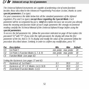
The Universal Infrared instruments are capable of performing a lot of extra functions besides those described in the Advanced Programming Procedure section, thanks to somespecial parameters (Cxx type).For your convenience the table below lists all the standard parameters of the Infrared regulators (Pxx and Cxx types) except those regarding the Special Mode. Each parameter will be accompanied by just a brief description because we assume you alreadyknow the meaning and function mode of each single parameter. We strongly recommendreading carefully the Technical Manual of the Universal Infrared Range before using thespecial parameters.To access the full parameter list, follow the procedure indicated on page 49 but replace thepassword “22” with “77”. If you enter the right password, the display will show the first parameter of the list, that is C0. To display and modify the value of the parameter follow theprocedure described above. Similarly, in order to confirm any modification, press “6”.
Par. Description Min. Max DefaultSt1 Set Point 1 min. probe max. probe 20St2 Set Point 2 (Function Modes 6, 7, 8, 9) min. probe max. probe 40C0 Function Mode (see page 42) 1 9 2
Setting the Hysteresis (see pages 37 and 42)P1 Hysteresis of Set Point 1 0.1 99.9 2.0P2 Hysteresis of SP 2 (F. Modes 3,4,5,7,8,9) 0.1 99.9 2.0P3 Dead-Band (Function Modes 3,4,5) 0 99.9 2.0
52
Advanced set-up: list of parameters
+05-3015 • rel.3.0 interno ok 18-09-2002 14:31 Pagina 52

53
Par. Description Min. Max DefaultC4 Compensation Coefficient. NTC only -2.0 2.0 0.5
and with Mode 1 or 2 & C19 = 2, 3 or 4.Consider D=NTC2 - SET2 :if C19 = 2when D<=0 SET1=SET1when D > 0 SET1=SET1+D*C4if C19 = 3when D>=0 SET1=SET1when D < 0 SET1=SET1+D*C4if C19 = 4when NTC2 > SET2+P2, SET1=SET1+(D-P2)*C4when NTC2 < SET2- P2, SET1=SET1+(D+P2)*C4
C5 Control action: 0=Prop(P), 1=Prop+Integ(P+I) 0 1 0
Parameters of the outputs C6 Delay between on routines of 2 different outs 0 999’’ 5’’C7 Minimum time between on routines
of the same output 0 5’ 0C8 Minimum off time of the same output 0 5’ 0C9 Minimum on time of the same output 0 15’ 0C10 Status of the outputs with probe alarm: 0 3 0
0 = All relay de-energized 1 = All relays energized 2 = Direct action relays energised, all others de-energised 3 = Reverse action relays energised, all others de-energ.
Advanced set-up: list of parameters
+05-3015 • rel.3.0 interno ok 18-09-2002 14:31 Pagina 53

Par. Description Min. Max DefaultC11 Output rotation: Modes 1, 2, 6,7,8 & models W&Z 0 7 0
0: no rotation1: standard rotation2: 2+2 rotation (compressor on outs 1 & 3)3: 2+2 rotation (valve normal open)4÷7: see technical manual
C12 time of PWM cycle 0,2’’ 999’’ 20’’
Probe parameters (see page 41)C13 Probe type: 0=4-20, 1=0-20; 0=K T/c, 1= J T/c 0 1 0
NTC input: if C13=1 the instrumentsdisplays NTC2 and controls on NTC1
P14 Probe calibration or offset -99 +99.9 0.0C15 Min.value for scaling of analogue inputs -99 C16 0.0C16 Max.value for scaling of analogue inputs C15 999 100C17 Probe response time (noise filter) 1 14 5C18 Temperature units: 0=°C, 1=°F 0 1 0C19 2nd probe: NTC only, Mode 1 or 2 0 4 0
0 = no modification of the Standard Mode1 = differential mode NTC1 - NTC22 = summer compensation 3 = winter compensation4 = active compensation with Dead-Band
54
Advanced set-up: list of parameters
+05-3015 • rel.3.0 interno ok 18-09-2002 14:31 Pagina 54
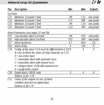
Par. Description Min. Max Default
Set-PointC21 Minimum Set-point 1 limit -99 C22 min. probeC22 Maximum Set-point 1 limit C21 999 max.probeC23 Minimum Set-point 2 limit -99 C24 min. probeC24 Maximum Set-point 2 limit C23 999 max.probe
Alarm Parameters (see pages 37 and 38)P25 Low absolute alarm Set-Point -99 P26 min.probeP26 High absolute alarm Set-Point P25 999 max.probeP27 Alarm hysteresis 0.1 99.0 2.0P28 Alarm Delay 0 120’ 0’C29 Config. of dig. input 1 (C0 must be different from 6,7,8) 0 4 0
In case of alarm the status of relays depends on C31)0 = non active input 1 = immediate alarm with automatic reset2 = immediate alarm with manual reset3 = delayed alarm (P28) with manual reset 4 = on/off of the control
C30 Digital Input 2 (IRDR only) 0 4 0Options as for C29
C31 Status of the outputs in case of alarm condition detected via digital input.Options as for C10
55
Advanced set-up: list of parameters
+05-3015 • rel.3.0 interno ok 18-09-2002 14:31 Pagina 55

Par. Description Min. Max Default
Other:C32 Address of unit for serial connection 1 16C33 Do NOT modify this parameter 0 1 0C50 Activation of Keypad (KP) and Remote Control(RC) 0 4 4
0 = KP off, RC ON (only type P parameters) (Def.=1 for1 = KP on, RC ON (only type P parameters) instr.with2 = KP off, RC OFF serial num.3 = KP on, RC OFF < 10.000)4 = KP on, RC ON (all parameters)
C51 Code to activate the IR remote control 0 120 0
56
Advanced set-up: list of parameters
+05-3015 • rel.3.0 interno ok 18-09-2002 14:31 Pagina 56

- Problem: keypad/remote control unit does not workCheck: see parameter C50.
- Problem: value changes repeatedlyCheck: - possible noise. See ‘Hints for Installation’ above.
- modify parameter C17 (decrease its value).- Problem: high/low alarms are not detected
Check: decrease alarm time delays. See parameters P25, P26 and P27- Problem: outputs not activated
Check: check time delays of the outputs; par. C6, C7, C8.- Problem: outputs are activated too often
Check: increase the value of the differential.See par. C6, C7 and C8.- Problem: the variable never reaches the set-point
Check: if the size of the entire system has been correctly calculated, the differential P1 or P2 should be decreased as well as the Dead-Band P3
- Problem: the value displayed does not correspond to the actual valueCheck: the position of the sensor (see page 35&36). For models with current,
voltage or J/K Tc input see the section “Special Parameters for Thermocouples” (see page 43).
Reset of the controlImportant: sometimes you may need to restore the factory-set configuration. To do so, follow these guidelines (Reset procedure):1 - cut off power 2 - supply the instrument while holding down ‘6’
57
Troubleshooting and Reset of the control
+05-3015 • rel.3.0 interno ok 18-09-2002 14:31 Pagina 57

Messages Description Cause SolutionEr0 probe error probe cable interrupted check connections
or short-circuited between instrum.&probeconnection error check probe signalfaulty probe (eg. NTC=10KΩ @25°C)
Er1 probe error see above but for see above but for (NTC only) NTC2 probe NTC2 NTC2 probeEr2 memory error supply cut off turn off then turn on
during programming he instrument again step holding down key “6”electrical noise if persists, replace the unit
Er3 external alarm digital input contact special function: seeopen parameter C29
check external contactEr4 HIGH alarm input has exceeded P26 check parameters
for more than P28 P26 and P28Er5 LOW alarm input is below P25 for check parameters
more than P28 P25 & P28
Warning: In case of alarm condition, the buzzer and the alarm code must be manuallyreset pressing the key ‘6’ (note: the alarm code will disappear only if the alarm is not stillpending). The alarm relay (Mode 5 only) is automatically reset when the alarm disappears;it can need a manual reset only for special value of P27 (Er4 & Er5) and of C29 (Er3) (seethe technical manual for details). In case of alarm type Er0, Er1, Er2 the normal functionof the unit restarts automatically when the alarm disappears; after a Er3 alarm the unitrestarts automatically or manually according to C29; Er4 & Er5 alarms do not affect thenormal function of the unit.
58
Troubleshooting
+05-3015 • rel.3.0 interno ok 18-09-2002 14:31 Pagina 58

59
Inputsaccording to model (see pag 32): Temperature: NTC, Pt100, K/J Thermoc.
Current 4/20 mA or 0/20 mAVoltage -0,4/+1 Vdc
Operating range: NTC: -50/90 °C, Pt100: -100/600 °C, ThcK: -100/999 °C, ThcJ: -100/800 °CCurrent/Voltage: see parameters C15 and C16
Resolution: 0.1or 1, according to decimal point selectionControler accuracy: ± 0.5 % of maximum range
Power supplyVoltage IR32D, W and Z: from 12 to 24 Vac-dc ±10%
IR32V: see pag.1 field ‘d’, tolerance±10%IRDRV and W: 24 Vac± 10% and 230 Vac ± 15%IRDRTE: 230 Vac ± 15%IRDRA and Z: from 12 to 24 Vac-dc, ± 10%
Power consumption: IR32A, D and V: 2VA; IR32W and IR32Z: 3VAIRDRTE, IRDRV, IRDRW and IRDRA: 3VAIRDRZ: 4VA
Probe power supply output: 10 Vdc, @ max 30mA (8Vdc for IRDRW)
Conditions of useWorking temperature: 0 ÷ 50 °CStorage temperature: -10 ÷ 70 °CRelative ambient humidity: lower than 90%rH, not condensingAmbient pollution: normal
Technical specifications
+05-3015 • rel.3.0 interno ok 18-09-2002 14:31 Pagina 59

60
InsulationThere is a basic insulation between the low voltage section and the very low voltage sectionand a double insulation between the low voltage section and the front panel.
OutputsNumber of relays: IR32 for NTC: 1, 2 or 4 SPDT relays (according to the mod.) others IR32V: 1 SPST relay;
IR32W: 1 SPST relay + 1 SPDT;IR32Z: 1 SPST relay+ 3 SPDTIRDRTE, IRDRV & W: 1 or 2 SPDT relaysIRDRZ: 1st and 2nd relays SPDT, 3rd & 4th SPSTIR32D: 1 output for SSR (solid status relay)IR32A and IRDRA: 4 outputs for SSR (solid status relay)
Relay features (all models): max.sw.voltage 250 Vac, max. sw.power 2000VA,max.inrush curr. 10A. Disconnection of type 1C according to ECC EN 60730-1
Signal caratcteristics for SSR output voltage: 10 Vdc; output resistance: 660 Ω(solid status relay) max. outputs voltage: 15 mA
Mechanical featuresConnections: IR32: panel mounting with hanger
IRDR: DIN rail mountingCases: plastic; IR32 autoextinguishing according to UL94-40Protection index: IR32: IP 65 with panel mounted instrument
IRDR: IP 40Connections: through screw terminals max. sect.1.5 mm2
Technical specifications
+05-3015 • rel.3.0 interno ok 18-09-2002 14:31 Pagina 60

Serial connection IR32: through accessory IR32SER (models indicated on pag.1) IRDR: through accessory IRDRSER
Parameters modification from keyboard, from serial and from remote control (for remote control accessory see price-list)
Important: cables should resist to maximum temperature, that is the maximum ambienttemper. allowed for the unit + controller (self heating is 20 °C max., with all outputs ON).
61
Technical specifications
+05-3015 • rel.3.0 interno ok 18-09-2002 14:31 Pagina 61

The range of the Carel Universal Infrared Instruments features absolutely innovative specifications and is certainly extremely competitive with any other regulator on the marketin this price bracket. And what’s more, the Infrared Series can be further enhanced with a complete range of accessories capable of making your instrument perform superbly.Here are some examples:
- Remote Control, for an easy programming procedureThe remote control unit for the Carel Universal Infrared regulators is available in the main languages. Modifying the working parameters is now as easy as to turn up or down thevolume of your TV set. For more information,contact your nearest dealer.
- Modi Kit for parameters modification via PCThe Modi Kit for Personal Computer is the best solution to the problem of centralized programming procedure. The Modi Kit allows you to store your standard configuration soas to tranfer it easily and quickly to all the Infrared instruments via serial connection.The Modi Kit makes your job easier since it prevents any error that may occur during themanual programming procedure by non-qualified personnel.
- Serial connectionAll IR instruments can be network connected to supervisory and telemaintenance systems.
- Package for Supervisory and Telemaintenance SystemsCarel has a wide range of software programmes available for any type of supervisory and telemaintenance requirement.Functions performed:
- variables monitoring and data storage on hard-disk (the trend of the variables can be displayed in a graph on a hourly, daily or monthly basis and printed whenever necessary);
- detection and storage of any off-normal condition (together with date and time of the alarm);- modification of the main parameters directly via PC.
62
Advanced programming tools and Supervisory systems
+05-3015 • rel.3.0 interno ok 18-09-2002 14:31 Pagina 62

63
Modi di funzionamento 1, 2 e 3 / Function Mode 1, 2 and 3
mod. Z mod. V mod. W
DD DDDD
OUT 1 OUT 2 OUT 3 OUT 4
Diff.(P1)
Set (St 1)
Diff.(P1)
Set (St 1)
OUT 1 OUT 2OUT 1
D
Diff.(P1)
Set (St 1)
mod. Z mod. V mod. W
RR RRRR
OUT 4 OUT 3 OUT 2 OUT 1
Diff.(P1)
Set (St 1)
Diff.(P1)
Set (St 1)
OUT 2 OUT 1OUT 1
R
Diff.(P1)
Set (St 1)
mod. Z
DD
Diff.(P2)
OUT 3 OUT 4
Neutral zone
(P3) (P3)
mod. W
OUT 1
R
Diff.(P1)
OUT 2
D
Diff.(P2)
Set (St 1)Neutral zone
(P3) (P3)
mod. V
OUT 1
R
Diff.(P1)
Set (St 1)
Neutral zone
(P3)
RR
Diff.(P1)
Set (St 1)
OUT 2 OUT 1
fig. 5: Mode 1
fig. 6: Mode 2
fig. 7: Mode 3
+05-3015 • rel.3.0 interno ok 18-09-2002 14:31 Pagina 63

64
Modi di funzionamento 4 e 5 / Function Mode 4 and 5
mod. Z
Diff.(P1)
Set (St 1)
OUT 2 OUT 1
Diff.(P2)
OUT 3 OUT 4
Neutral zone
(P3) (P3)R R D D
mod. V
OUT 1
R
Diff.(P1)
Set (St 1)
Neutral zone
(P3)
mod. W
OUT 1
Diff.(P1)
OUT 2
Diff.(P2)
Set (St 1)Neutral zone
(P3) (P3)
R D
mod. Z
OUT 1
R
Diff.(P1)
OUT 2
D
Diff.(P2)
Set (St 1)Neutral zone
(P3) (P3)
OUT 4
Diff.(P27)
(P26)
OUT 3
Diff.(P27)
Low Alarm (P25) High Alarm
mod. W
OUT 1
R
Diff.(P1)
Set (St 1)
Neutral zone
(P3)
OUT 2
Diff.(P27)
(P25/P26)
High/Low Alarm
OUT 1
Diff.(P27)
(P25/P26)
High/Low Alarm
mod. V
fig. 8: Mode 4
fig. 9: Mode 5
+05-3015 • rel.3.0 interno ok 18-09-2002 14:31 Pagina 64

65
Modi di funzionamento 6 e 7 / Function Mode 6 and 7
INGRESSO DIGITALE APERTO/ DIGITAL INPUT OPEN
INGRESSO DIGITALE CHIUSO/ DIGITAL INPUT CLOSED
RR RRRR
OUT 4 OUT 3 OUT 2 OUT 1
Diff.(P2)
Set (St 2)
Diff.(P2)
Set (St 2)
OUT 2 OUT 1OUT 1
R
Diff.(P2)
Set (St 2)
mod. Z mod. V mod. W
DD DDDD
OUT 1 OUT 2 OUT 3 OUT 4
Diff.(P1)
Set (St 1)
Diff.(P1)
Set (St 1)
OUT 1 OUT 2OUT 1
D
Diff.(P1)
Set (St 1)
INGRESSO DIGITALE APERTO/ DIGITAL INPUT OPEN
INGRESSO DIGITALE CHIUSO/ DIGITAL INPUT CLOSED
OUT 4 OUT 3 OUT 2 OUT 1
Diff.(P2)
Set (St 2)
Diff.(P2)
Set (St 2)
OUT 2 OUT 1OUT 1
Diff.(P2)
Set (St 2)
mod. Z mod. V mod. W
DD DDDD
OUT 1 OUT 2 OUT 3 OUT 4
Diff.(P1)
Set (St 1)
Diff.(P1)
Set (St 1)
OUT 1 OUT 2OUT 1
D
D D D D D D D
Diff.(P1)
Set (St 1)
fig. 11: Mode 7
fig. 10: Mode 6
+05-3015 • rel.3.0 interno ok 18-09-2002 14:31 Pagina 65

66
Modi di funzionamento 8 e 9 / Function Mode 8 and 9
INGRESSO DIGITALE APERTO/ DIGITAL INPUT OPEN
INGRESSO DIGITALE CHIUSO/ DIGITAL INPUT CLOSED
RR RRRR
OUT 4 OUT 3 OUT 2 OUT 1
Diff.(P2)
Set (St 2)
Diff.(P2)
Set (St 2)
OUT 2 OUT 1OUT 1
R
RR RRRRR
Diff.(P2)
Set (St 2)
mod. Z mod. V mod. W
OUT 1 OUT 2 OUT 3 OUT 4
Diff.(P1)
Set (St 1)
Diff.(P1)
Set (St 1)
OUT 1 OUT 2OUT 1
Diff.(P1)
Set (St 1)
mod. W
mod. Z
Diff.(P1)Set (St 1)
OUT 1
R
Diff.(P1)
Set (St 1)
OUT 2
D
Diff.(P2)
Set (St 2)
Diff.(P2)Set (St 2)
DD
OUT 3 OUT 4RR
OUT 2 OUT 1
fig. 12: Mode 8
fig. 13: Mode 9
+05-3015 • rel.3.0 interno ok 18-09-2002 14:31 Pagina 66

67
IR32 V vers. NTC: Collegamenti / Connections
c
1 2 3 654 7 8 9DIG.INPOWER NTC1 NTC2COM
OUT 1
SERIALLINK
12÷24 V2 VA
c
POWER
mod. H 110÷240
1 2 3
19 20
6 7 8 9DIG.IN NTC1 NTC2COM
_~
mod. U 24÷240_~
OUT 1
Versione V, alimentazione24÷240 o 110÷240Vac/Vdc, ingresso NTC
Version V, power supply24÷240 o110÷240Vac/Vdc, NTCinput
Versione V, alimentazione12÷24Va/Vdc e ingressoNTC
Version V, power supply12÷24 Vac/Vdc, NTC input
+05-3015 • rel.3.0 interno ok 18-09-2002 14:31 Pagina 67

68
IR32 A & D, vers. NTC: Collegamenti / Connections
OUT 1
POWER
1 2 5 6 7 8 9DIG.INCOM
+ -
3 4POWER
- +S
ER
IAL
LIN
K
12-24 V3 VA
NTC1 NTC2COM
OUT 1
POWER
1 2 5 6DIG.INCOM
+ -
3 4POWER
- +
SE
RIA
L L
INK
OUT 2OUT 3 OUT 4
10 11 12 13 14 15 16 17 18
+ + +
12-24 V3 VA
7 8 9NTC1 NTC2COM
Versione A, alimentazione12÷24 Vac/Vdc, ingressoNTC
Version A, power supply12÷24Vac/Vdc, NTC input
Versione D, alimentazione12÷24 Vac/Vdc, ingressoNTC
Version D, power supply12÷24Vac/Vdc, NTC input
+05-3015 • rel.3.0 interno ok 18-09-2002 14:31 Pagina 68
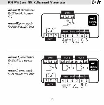
69
IR32 W & Z vers. NTC: Collegamenti / Connections
c
1 2 3 654 7 8 9DIG.INPOWER NTC1 NTC2COM
OUT 1
SERIALLINK
12÷24 V2 VA
OUT 2
13 14 15
c
OUT 3
10 11 12
c
OUT 4
16 17 18
c
c
1 2 3 654 7 8 9DIG.INPOWER NTC1 NTC2COM
OUT 1
SERIALLINK
12÷24 V2 VA
OUT 2
13 14 15
c
Versione W, alimentazione12÷24 Vac/Vdc, ingressoNTC
Version W, power supply12÷24Vac/Vdc, NTC input
Versione Z, alimentazione12÷24Va/Vdc e ingressoNTC
Version Z, power supply12÷24 Vac/Vdc, NTC input
+05-3015 • rel.3.0 interno ok 18-09-2002 14:31 Pagina 69

70
IR32 V not NTC: Collegamenti / Connections
c
OUT 1
1 2 3 4 5 6 7 8 9POWER DIG.INCOM
12-24 V2 VA
_~
SERIALLINK
- +(vedi/see fig. 14)
c
POWER
mod. H 110÷240
1 2
19 20
65 7 8 9DIG.INCOM
_~
mod. U 24÷240_~
OUT 1(vedi/see fig. 14)
Versione V, alimentazione24÷240 o 110÷240Vac/Vdc e ingresso Pt100o Tc J/K o V/I
Version V, power supply24÷240 o110÷240Vac/Vdc andPt100 or J/K Tc or V/Iinput
Versione V, alimentazione12÷24 Vac/Vdc e ingressoPt100 o Tc J/K o V/I
Version V, power supply12÷24Vac/Vdc and Pt100or J/K Tc or V/I input
+05-3015 • rel.3.0 interno ok 18-09-2002 14:31 Pagina 70

71
IR32 A & D, not NTC: Collegamenti / Connections
OUT 1
POWER
1 2 5 6 7 8 9DIG.INCOM
+ -
3 4POWER
- +
SE
RIA
L L
INK
12-24 V3 VA
(vedi/see fig. 14)
OUT 1
POWER
1 2 5 6 7 8 9DIG.INCOM
+ -
3 4POWER
- +
SE
RIA
L L
INK
OUT 2OUT 3 OUT 4
10 11 12 13 14 15 16 17 18
+ + +
12-24 V3 VA
(vedi/see fig. 14)
Versione A, alimentazione12÷24 Vac/Vdc
Version A, power supply12÷24Vac/Vdc
Versione D, alimentazione12÷24 Vac/Vdc
Version D, power supply12÷24Vac/Vdc
+05-3015 • rel.3.0 interno ok 18-09-2002 14:31 Pagina 71

72
IR32 W & Z not NTC: Collegamenti / Connections
SERIALLINK
OUT 2
13 14 15
c
OUT 3
10 11 12
c
OUT 4
16 17 18
c
c
OUT 112-24 V
3 VA
1 2 3 4 5 6 7 8 9POWER DIG.INCOM
_~- +(vedi/see fig. 14)
c
1 2 3 654 7 8 9DIG.IN NTC1 NTC2COM
OUT 1
SERIALLINK
POWER
12÷24 V2 VA
- +
OUT 2
13 14 15
c
(vedi/see fig. 14)
Versione W, alimentazione12÷24 Vac/Vdc e ingressoPt100 o Tc J/K o V/I
Version W, power supply12÷24Vac/Vdc and Pt100or J/K Tc or V/I input
Versione Z, alimentazione12÷24 Vac/Vdc e ingressoPt100 o Tc J/K o V/I
Version Z, power supply12÷24Vac/Vdc and Pt100 orJ/K Tc or V/I input
+05-3015 • rel.3.0 interno ok 18-09-2002 14:31 Pagina 72

73
IRDR TE & IRDR V: Collegamenti / Connections
OUT 1
PROBEDIG.2 COM. DIG.1
1 2 3
c
220240V 0
POWER
24V
SERIALLINK
~ ~
(vedi/see fig. 15)
220240VOUT 1
PROBEDIG.2 COM. DIG.1
0
POWER
NTCp2 p1
1 2 3
c
~Versione TE, alimentazione220÷240 Vac/Vdc, ingressoNTC
Version W, power supply220÷240Vac/Vdc, NTC input
Versione V, alimentazione24÷240 Vac/Vdc, ingressoNTC o Pt100 o Tc J/K o V/I
Version V, power supply24÷240Vac/Vdc, NTC orPt100 or J/K Tc or V/I input
+05-3015 • rel.3.0 interno ok 18-09-2002 14:31 Pagina 73

74
IRDR W & IRDR Z: Collegamenti / Connections
OUT 1
PROBEDIG.2 COM. DIG.1
1 2 3
c
OUT 2
c
220240V 0
POWER
24V
SERIALLINK
~ ~
(vedi/see fig. 15)
Versione W, alimentazione24÷230 Vac/Vdc, ingressoNTC o Pt100 o Tc J/K o V/I
Version W, power supply24÷230Vac/Vdc, NTC orPt100 or J/K Tc or V/I input
Versione Z, alimentazione12÷24 Vac/Vdc, ingressoNTC o Pt100 o Tc J/K oV/I
Version Z, power supply12÷24Vac/Vdc, NTC orPt100 or J/K Tc or V/Iinput PROBEDIG.2 COM. DIG.1
1 2 3SERIAL
LINK
OUT 1OUT 3 OUT 2 OUT 4
POWER
12-24 V3 VA
c c
- +(vedi/see fig. 15)
+05-3015 • rel.3.0 interno ok 18-09-2002 14:31 Pagina 74

75
IRDR A: Collegamenti / Connections
PROBEDIG.2 COM. DIG.1
1 2 3SERIAL
LINK
OUT 1OUT 3 OUT 2 OUT 4
POWER
12-24 V3 VA
- ++ - + - + -+ -
com.
(vedi/see fig. 15)
Versione A, alimentazione12÷24 Vac/Vdc, ingressoNTC o Pt100 o Tc J/K o V/I
Version A, power supply12÷24Vac/Vdc, NTC orPt100 or J/K Tc or V/I input
+05-3015 • rel.3.0 interno ok 18-09-2002 14:31 Pagina 75

76
Connessione sonde / Probe connections
Pt100 TcJ/K V/I
OUTM +10
1 2 37 8 9 7 8 9 7 8 9
(*)Probe Connections/ Connessione Sonde
1 2 3
Pt100 TcJ/K V/I
OUTM +10
NTC
p2 p1
1 2 31 2 3 1 2 3 1 2 3
(*)Probe Connections/ Connessione Sonde
fig. 14
fig. 15
IR32
IRDR
(*) ad ogni tipo di sonda corrisponde uno specifico modelloeach probe type requires its specific model
Note1) Nel caso di sonde Pt100 a 2 fili cortocircui-
tare i morsetti 8 e 9 (IR32) o 2 e 3 (IRDR)2) Collegare l’eventuale schermatura della
sonda alla terra del quadro elettrico. Nel caso di termocoppie, è necessario usare sonde con cavo schermato per avere una corretta immunità ai disturbi
3) Per le sonde in tensione e/o corrente considerare che la massima tensione fornita è 10 Vdc @ 30 mA (max 8Vdc per IRDRW).
Notes1) The use of Pt100 2 Wires requires you to
short circuit connectors 8 and 9 (IR32) or2 and 3 (IRDR)
2) Connect the probe braiding to the electrical panel ground. When using thermocouples, use screened probes to avoid noises.
3) When using voltage or current probes consider that the maximun voltage outputis 10 V dc @ 30mA (max 8 Vdc for IRDRW).
+05-3015 • rel.3.0 interno ok 18-09-2002 14:31 Pagina 76

77
Connessione sonde Carel / Carel probe connections
7 8 9
1 2 3
IR32IRDR
ponticello / bridge
Pt100Ecavi dello stesso colorewires with the same color
Pt100A1/A2
rosso / redblu/ blue
TcJ
rosso / redverde/ green
TcK
bianco / white
marrone/ brown
out Tor
out HM +
SpK
Sonde attiveActive probe
+05-3015 • rel.3.0 interno ok 18-09-2002 14:31 Pagina 77

78
Dimensioni / Dimensions
71 x 29 mm
6471,5
75
33
reverse direct PRGmute
SEL
PRGmute
reverse directSEL
88
70
59,1
+05-3015 • rel.3.0 interno ok 18-09-2002 14:31 Pagina 78

Note:
+05-3015 • rel.3.0 interno ok 18-09-2002 14:31 Pagina 79

Note:
+05-3015 • rel.3.0 interno ok 18-09-2002 14:31 Pagina 80

Interfaccia utente/ user interface
reverse direct PRGmute
SEL
12
3 4 56
78
PRGmute
reverse directSEL
12
3 4 5 6
78
IR32fig. 1
IRDRfig. 2
CAREL S.p.A.Via dell’Industria, 11 - 35020 Brugine - Padova (Italy)Tel. (+39) 049.9716611 Fax (+39) 049.9716600http://www.carel.com – e-mail: [email protected]
Cod
.:+0
5000
3015
rel
.3.0
- 04
/09/
2002
manuale d’uso
user manual
Indice . . . . . . 3Contents . . . . . . 33Diagrammi / Diagrams . . . . . 62Collegamenti / Connections . . . . 66Connessione sonde / Probe connections . . . 74Connessione sonde Carel / Carel probes connections . . 75Dimensioni / Dimensions . . . . 76
universal infrared series
1 - Display2 - Led decimale3 - Led reverse4 - Led direct5 - Tasto SEL: visualizza il Set Point. Se premuto insieme al tasto PRG-Mute per 5 s.
permette di accedere ai parametri di configurazione (con codice tipo ‘Cxx’).6 - Tasto PRG/Mute: premuto per 5 secondi da’ accesso al menu’ dei parametri di utilizzo più
frequente (codice tipo ‘Pxx’). In caso di allarme tacita il buzzer. Resetta le altre segnalazioni d’allarme se premuto al cessare della causa.
7 - Tasto “Freccia Sù”: incrementa il valore del parametro selezionato.8 - Tasto “Freccia Giù”: decrementa il valore del parametro selezionato. Nelle versioni NTC, se
premuto quando sul display e’ visualizzato il valore della sonda principale permette la visualizzazione della seconda sonda.
1 - Display 2 - Decimal Point3 - Led reverse4 - Led direct 5 - Key SEL: displays the Set-point. Hold it down for more than 5 seconds together
with the PRG-MUTE key to access the Configuration menu (code type ‘Cxx’ ).
6 - Key PRG/MUTE: Hold it down for 5 seconds to access the menu of the more frequently used parameters (code type ‘Pxx’). In the event of alarm condition, press it to silence the buzzer.
7 - Key UP: increases the value of the selected parameter.8 - Key DOWN: decreases the value of the selected parameter. For NTC input versions,
if pressed when the main probe value is displayed, it displays the second probe value.


