1 Using LED Lighting for Ubiquitous Indoor Wireless Networking T.D.C. Little, P. Dib, K. Shah, N. Barraford, and B. Gallagher June 1, 2008 MCL Technical Report No. TR-05-20-2008 Abstract—Wireless networking is currently dominated by radio frequency (RF) techniques. However, the soon-to-be ubiquity of LED-based lighting motivated by significant energy savings provides an opportunistic deployment of widespread free-space optical (FSO) communications. LED- based network transceivers have a variety of competitive advantages over RF including high bandwidth density, security, energy consumption, and aesthetics. They also use a highly reusable unregulated part of the spectrum (visible light). In this paper we describe results from a pilot project to demonstrate the viability of an optical free-space visible light transceiver as a basis for indoor wireless networking. Inexpensive, commercial, off-the shelf LEDs and photodiodes we used to construct two prototypes; a simplex channel as expected as a component of an asymmetric/hybrid RF- FSO system, and a full-duplex channel demonstrating the ability to isolate multiple channels. On— off keying (OOK) was applied without observable flicker in the target modulation ranges. Results indicate the viability of creating inexpensive FSO transceivers that might be embedded in commercial lighting products to support ceiling-to-floor distances of approximately 3m. Index Terms—Wireless networking, indoor communications, free-space optical communications, visible light LED, modulation, OOK, FSO.
Transcript
1
Using LED Lighting for Ubiquitous Indoor Wireless Networking
T.D.C. Little, P. Dib, K. Shah, N. Barraford, and B. Gallagher
June 1, 2008
MCL Technical Report No. TR-05-20-2008
Abstract—Wireless networking is currently dominated by radio frequency (RF) techniques. However, the soon-to-be ubiquity of LED-based lighting motivated by significant energy savings provides an opportunistic deployment of widespread free-space optical (FSO) communications. LED-based network transceivers have a variety of competitive advantages over RF including high bandwidth density, security, energy consumption, and aesthetics. They also use a highly reusable unregulated part of the spectrum (visible light). In this paper we describe results from a pilot project to demonstrate the viability of an optical free-space visible light transceiver as a basis for indoor wireless networking. Inexpensive, commercial, off-the shelf LEDs and photodiodes we used to construct two prototypes; a simplex channel as expected as a component of an asymmetric/hybrid RF-FSO system, and a full-duplex channel demonstrating the ability to isolate multiple channels. On—off keying (OOK) was applied without observable flicker in the target modulation ranges. Results indicate the viability of creating inexpensive FSO transceivers that might be embedded in commercial lighting products to support ceiling-to-floor distances of approximately 3m. Index Terms—Wireless networking, indoor communications, free-space optical communications, visible light LED, modulation, OOK, FSO.
2
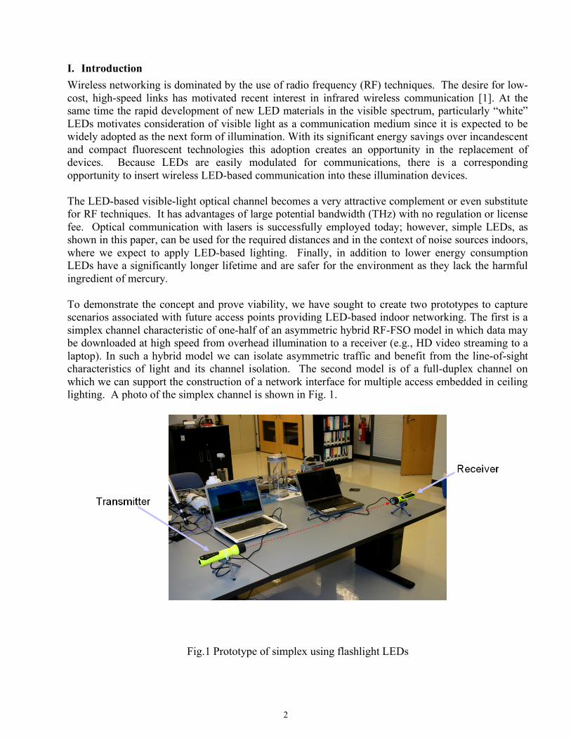
I. Introduction Wireless networking is dominated by the use of radio frequency (RF) techniques. The desire for low-cost, high-speed links has motivated recent interest in infrared wireless communication [1]. At the same time the rapid development of new LED materials in the visible spectrum, particularly “white” LEDs motivates consideration of visible light as a communication medium since it is expected to be widely adopted as the next form of illumination. With its significant energy savings over incandescent and compact fluorescent technologies this adoption creates an opportunity in the replacement of devices. Because LEDs are easily modulated for communications, there is a corresponding opportunity to insert wireless LED-based communication into these illumination devices. The LED-based visible-light optical channel becomes a very attractive complement or even substitute for RF techniques. It has advantages of large potential bandwidth (THz) with no regulation or license fee. Optical communication with lasers is successfully employed today; however, simple LEDs, as shown in this paper, can be used for the required distances and in the context of noise sources indoors, where we expect to apply LED-based lighting. Finally, in addition to lower energy consumption LEDs have a significantly longer lifetime and are safer for the environment as they lack the harmful ingredient of mercury. To demonstrate the concept and prove viability, we have sought to create two prototypes to capture scenarios associated with future access points providing LED-based indoor networking. The first is a simplex channel characteristic of one-half of an asymmetric hybrid RF-FSO model in which data may be downloaded at high speed from overhead illumination to a receiver (e.g., HD video streaming to a laptop). In such a hybrid model we can isolate asymmetric traffic and benefit from the line-of-sight characteristics of light and its channel isolation. The second model is of a full-duplex channel on which we can support the construction of a network interface for multiple access embedded in ceiling lighting. A photo of the simplex channel is shown in Fig. 1.
Fig.1 Prototype of simplex using flashlight LEDs
3
Using off the shelf components (hollow flashlights as packaging, low cost circuitry and LEDs), the prototype supports communication between two computers using a serial link (we used PuTTY [2] and USB/RS-232). The transmitter and receiver are powered by 9V batteries.
Fig.2 System Block Diagram of simplex channel The simplex channel permits transmission in one direction only. Fig. 2 shows the overall signal flow. By connecting computers at each end we can demonstrate the transmission of ASCII characters from on terminal to the next using the visible light channel. The signal chain uses visible light through an array of 10 LEDs. The receiver employs an array of 3 photodiodes and corresponding OOK decoding circuitry. In the remainder of the paper we describe related work in LED-based communications (Sec. II), modulation (Sec. III), frequency considerations (Sec. IV), performance (Sec. V), the duplex channel (Sec. VI). Section VII concludes the paper.
II. Preliminaries
A. LED vs. Laser
LEDs are constructed from direct band-gap semiconductor materials whose band-gap energies correspond to frequencies in the visible spectrum. In order to make LEDs efficiently emit light, this is typically accomplished through forward biasing a p-n junction. The current flowing through the junction allows for the rate of the radiative electron-hole recombination to be large. The light emitted from this radiative recombination is in the form of spontaneous emission and is radiated uniformly in all directions.
Laser diodes are made from similar materials as LEDs however they are generally more heavily doped to allow the materials to act as a semiconductor optical amplifier. As with all lasers feedback is required. In laser diodes it can take the simple form of cleaved surfaces which take advantage of internal reflections from the difference of indexes of refraction or engineered Distributed Bragg Reflectors [6]. The light emitted from laser diodes is in the form of stimulated emission.
Typical characteristics of LEDs and Laser diodes that can be used as a basis for comparison are their respective spectral intensities, efficiencies, and output optical powers. The spectral intensity of LEDs is very broad in comparison with that of the laser diode which is very narrow as a result of stimulated emission. Overall laser diodes are also more efficient with respect to power conversion efficiency and the output optical power is generally much greater. This arises from the fact that the laser light is
4
concentrated into particular modes, which are able to be extracted better than the spontaneous emission of the LED. Laser diodes can be characterized by high intensity, spatially confined beams of light. LEDs on the other hand produce light that is not spatially confined and diffuses readily. From a communications standpoint, using laser light as the medium allows for significantly greater distance separations and higher data rates. However, because laser light has higher intensities in a smaller area it can be harmful to the human eye and would prove difficult to simultaneously provide illumination. LEDs can provide illumination but because they produce diffuse light they are more sensitive to separation distances.
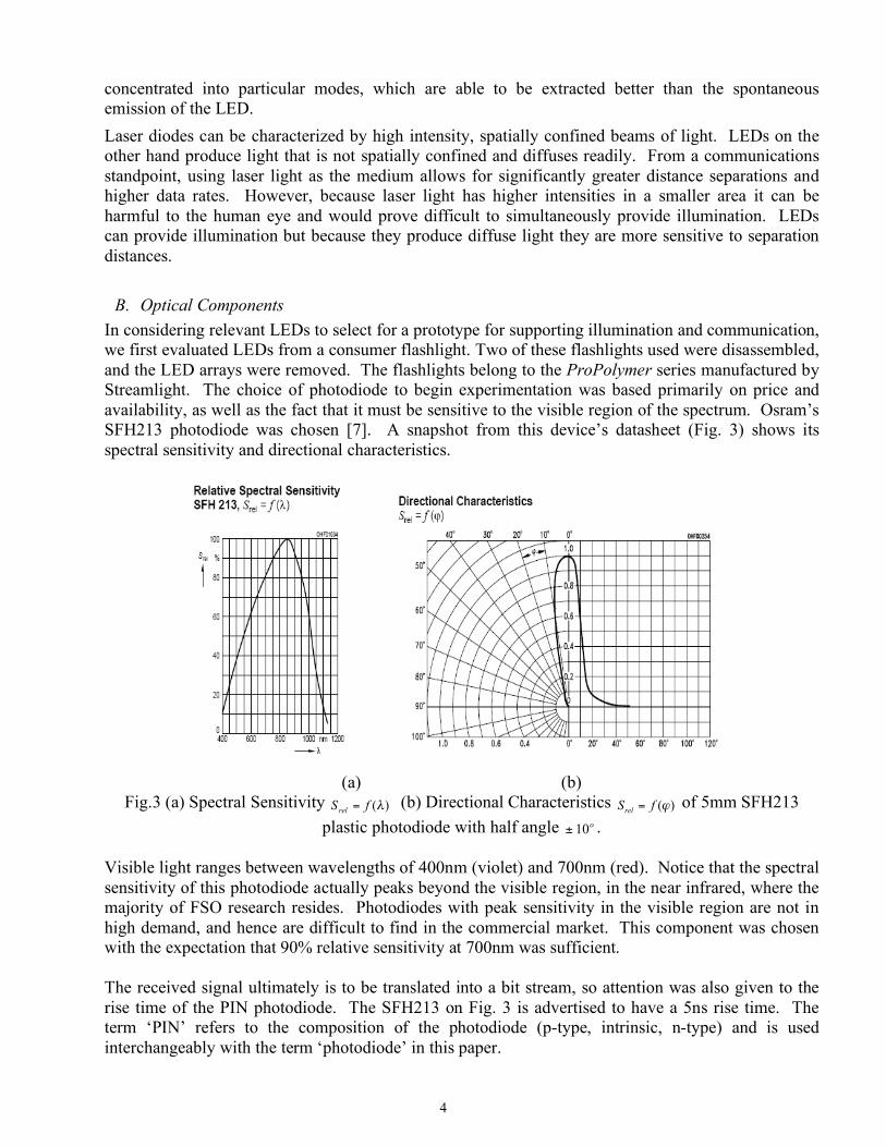
B. Optical Components In considering relevant LEDs to select for a prototype for supporting illumination and communication, we first evaluated LEDs from a consumer flashlight. Two of these flashlights used were disassembled, and the LED arrays were removed. The flashlights belong to the ProPolymer series manufactured by Streamlight. The choice of photodiode to begin experimentation was based primarily on price and availability, as well as the fact that it must be sensitive to the visible region of the spectrum. Osram’s SFH213 photodiode was chosen [7]. A snapshot from this device’s datasheet (Fig. 3) shows its spectral sensitivity and directional characteristics.
(a) (b)
Fig.3 (a) Spectral Sensitivity )(!fS rel = (b) Directional Characteristics )(!fSrel = of 5mm SFH213 plastic photodiode with half angle o
10± . Visible light ranges between wavelengths of 400nm (violet) and 700nm (red). Notice that the spectral sensitivity of this photodiode actually peaks beyond the visible region, in the near infrared, where the majority of FSO research resides. Photodiodes with peak sensitivity in the visible region are not in high demand, and hence are difficult to find in the commercial market. This component was chosen with the expectation that 90% relative sensitivity at 700nm was sufficient. The received signal ultimately is to be translated into a bit stream, so attention was also given to the rise time of the PIN photodiode. The SFH213 on Fig. 3 is advertised to have a 5ns rise time. The term ‘PIN’ refers to the composition of the photodiode (p-type, intrinsic, n-type) and is used interchangeably with the term ‘photodiode’ in this paper.
5
We assumed that purchasing a photodiode with a preamp would substantially increase the range of the received signal. Hamamatsu’s S6468 Silicon PIN was chosen based again on the spectral response and fast rise time. Unfortunately upon evaluation, we did not realize this improvement in signal range. Rather, there was a significant decline in performance. We suspect that the Hamamatsu PIN includes a filter that incorrectly identifies the LED signal as noise, as the distance increases and the light is diminished. The separation distance (distance between LED and photodetector) was measured by powering the LED array with a function generator (2V peak-peak square wave with a 1V offset) and by holding the photodiode under test some measurable distance away. Following these experiments (Fig. 4), we decided to use the SFH213 components for the prototype and incorporate an external amplifier in the design.
Fig.4 Received intensity with distance of SFH213 photodiode
We expected that the overhead lighting in the laboratory would interfere with the signals transmitted by the LEDs and preparations had been made to purchase optical filters and focusing components to alleviate this problem. During experimentation, a second advantage to using the SFH213 was discovered in the inherent directionality of the PIN. The operator needed to carefully align the photodiode with the LED array to obtain realistic signal readings, but with the photodiode pointed along the table (perpendicular to the overhead lights), there was minimal background noise. This constant level of inconsequential noise did not interfere with the signal. The directional characteristics of the PIN (shown in Fig. 3b) allow experiments to be conducted, and the prototype to be demonstrated, in a normally illuminated room. Furthermore, the size and shape of the SFH213 permitted reuse of the flashlight reflectors to contain the accepted light. The reflector on the flashlight functions to increase the forward intensity of the LEDs by redirecting the backward scattered light. Having a reflector at both the transmitting end of the prototype (around the LEDs) and the receiving end (around the photodiodes) inevitably increased the performance of the system.
6
III. Frequency Considerations We decided to use On-Off Keying (OOK) as a modulation scheme meaning that the frequency study is very important in the photonics components and in the circuit design of the communication interface.
A. Photodiode Response The frequency characteristics of the photodiodes purchased proved to be a limiting factor of the maximum achievable data rate of our system. The Osram SFH213 photodiodes advertised rise and fall times of 5 ns, which would directly translate to an upper bound frequency of 200 MHz. Initially we set up the photodiodes reverse biased, connecting in series to a 100 kΩ resistor going to ground. We found that when we applied a square wave with a frequency of 10 kHz that it became distorted and appeared as a saw-tooth function instead of the square wave. Initial suspicions were directed at the LEDs as the limiting component on bandwidth. However, when we set up the Hamamatsu photodiodes we found that in fact the limitation was caused by the photodiodes [8]. By readjusting the resistive component in both the sender and receiver we were able to increase the input frequency to the 50kHz range. (With the simple modulation scheme we were ultimately limited by the absence of a self-clocking receiver, not the limits of the devices on the physical channel.)
B. Voltage Reference Effect on Frequency Another factor that affected the maximum frequency of the system was the value of the voltage reference for the comparator to convert to TTL logic. Using the slope coupling trigger feature of the oscilloscope we were able to see the actual signal for a given ASCII character. Due to the saw-tooth behavior of our photodiodes at high frequencies, the photodiodes were not able to make full transitions in the short bit times required. Therefore, raising the voltage reference we were able to “catch” these incomplete transitions. However, the reference voltage also needs to be a low enough so as not to mistake noise as the signal and make false transitions. We found that by using a reference voltage of three volts we were able to achieve data rates above 56 kbps.
IV. COMMUNICATION INTERFACE The communication interface subsystem is the design of the hardware interface that will modulate and demodulate the signal using OOK modulation scheme. Several infrared research prototypes described in [3] and [4] used OOK with a successful implementation in the range of 5-20Mb/s. The block diagram circuit of the simplex channel that we designed is shown in Fig. 5.
7
Fig. 5 Simplex channel communication interface (transmitter & receiver)
A. Transmitter Circuit A link between the USB/RS-232 cable and the LEDs was necessary to convert the signal from serial to TTL. Our original design is based on a laser transceiver circuit. It consists of an opto-isolator (4N33) and a hex-inverter (open collector). The opto-isolator couples a standard RS-232 signal from the computer to the driver section of the circuit. The hex-inverter has all its output coupled together to provide enough drive current for the LEDs. This configuration was designed so that when no signal is present the LEDs are still ON. Once the transmitter circuit was successfully working, we switch the opto-isolator with the MAX232A chip (transceiver). This last component is explained in the Post-Receiver Circuit section.
B. Receiver Circuit The noisy low power signal received from the photodiodes was sent to the input of an LM741 operational amplifier. The amplifier had a non-inverting gain of 51. This amplified version of the signal was then sent to the AP393 comparator so as to clip the amplified signal between 0-5V making it TTL. As mentioned previously we used a reference voltage to set the transition point which was a critical value in determining the maximum frequency attainable. The output TTL voltage from the comparator was then sent to MAX232A transceiver chip so that it can be sent over the USB/RS232 cable to the laptop.
V. Analysis, Simulations, & Results To characterize the performance of the design we studied the distance versus intensity and also the link budget of a simplex channel. A link budget is the accounting of all the gains and losses from the transmitter, through the medium (free space, cable, waveguide, fiber, etc) to the receiver in the communication channel. It accounts for the attenuation of the transmitted signal due to propagation, as well as the antenna gains, feed-line and
8
miscellaneous losses. Randomly varying channel gains such as fading are taken into account by adding some margin depending on the anticipated severity of its effects. The amount of margin required can be deduced by the use of mitigating techniques such as antenna diversity or frequency hopping. A link budget is useful because it gives the theoretical bounds on data rate, bit error probability and distance between the transmitter and the receiver.
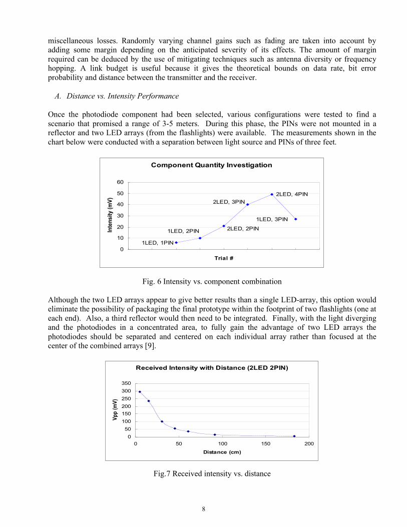
A. Distance vs. Intensity Performance Once the photodiode component had been selected, various configurations were tested to find a scenario that promised a range of 3-5 meters. During this phase, the PINs were not mounted in a reflector and two LED arrays (from the flashlights) were available. The measurements shown in the chart below were conducted with a separation between light source and PINs of three feet.
Component Quantity Investigation
1LED, 3PIN
2LED, 4PIN
2LED, 3PIN
2LED, 2PIN1LED, 2PIN
1LED, 1PIN
0
10
20
30
40
50
60
Trial #
Inte
nsit
y (
mV
)
Fig. 6 Intensity vs. component combination
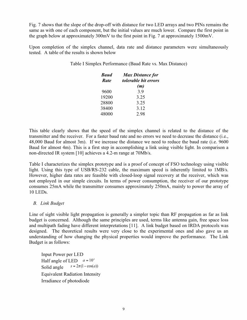
Although the two LED arrays appear to give better results than a single LED-array, this option would eliminate the possibility of packaging the final prototype within the footprint of two flashlights (one at each end). Also, a third reflector would then need to be integrated. Finally, with the light diverging and the photodiodes in a concentrated area, to fully gain the advantage of two LED arrays the photodiodes should be separated and centered on each individual array rather than focused at the center of the combined arrays [9].
Received Intensity with Distance (2LED 2PIN)
0
50
100
150
200
250
300
350
0 50 100 150 200
Distance (cm)
Vp
p (
mV
)
Fig.7 Received intensity vs. distance
9
Fig. 7 shows that the slope of the drop-off with distance for two LED arrays and two PINs remains the same as with one of each component, but the initial values are much lower. Compare the first point in the graph below at approximately 300mV to the first point in Fig. 7 at approximately 1500mV. Upon completion of the simplex channel, data rate and distance parameters were simultaneously tested. A table of the results is shown below
Table I Simplex Performance (Baud Rate vs. Max Distance)
Baud Rate
Max Distance for tolerable bit errors
(m) 9600 3.9
19200 3.25 28800 3.25 38400 3.12 48000 2.98
This table clearly shows that the speed of the simplex channel is related to the distance of the transmitter and the receiver. For a faster baud rate and no errors we need to decrease the distance (i.e., 48,000 Baud for almost 3m). If we increase the distance we need to reduce the baud rate (i.e. 9600 Baud for almost 4m). This is a first step in accomplishing a link using visible light. In comparison a non-directed IR system [10] achieves a 4.2-m range at 70Mb/s. Table I characterizes the simplex prototype and is a proof of concept of FSO technology using visible light. Using this type of USB/RS-232 cable, the maximum speed is inherently limited to 1MB/s. However, higher data rates are feasible with closed-loop signal recovery at the receiver, which was not employed in our simple circuits. In terms of power consumption, the receiver of our prototype consumes 25mA while the transmitter consumes approximately 250mA, mainly to power the array of 10 LEDs.
B. Link Budget Line of sight visible light propagation is generally a simpler topic than RF propagation as far as link budget is concerned. Although the same principles are used, terms like antenna gain, free space loss and multipath fading have different interpretations [11]. A link budget based on IRDA protocols was designed. The theoretical results were very close to the experimental ones and also gave us an understanding of how changing the physical properties would improve the performance. The Link Budget is as follows:
Input Power per LED Half angle of LED o
a 10= Solid angle ))cos(1(2 as != " Equivalent Radiation Intensity Irradiance of photodiode
10
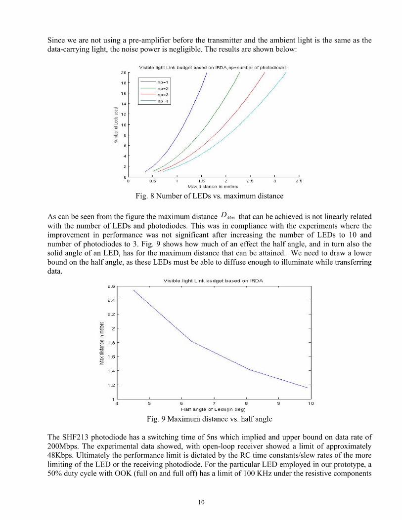
Since we are not using a pre-amplifier before the transmitter and the ambient light is the same as the data-carrying light, the noise power is negligible. The results are shown below:
Fig. 8 Number of LEDs vs. maximum distance
As can be seen from the figure the maximum distance Max
D that can be achieved is not linearly related with the number of LEDs and photodiodes. This was in compliance with the experiments where the improvement in performance was not significant after increasing the number of LEDs to 10 and number of photodiodes to 3. Fig. 9 shows how much of an effect the half angle, and in turn also the solid angle of an LED, has for the maximum distance that can be attained. We need to draw a lower bound on the half angle, as these LEDs must be able to diffuse enough to illuminate while transferring data.
Fig. 9 Maximum distance vs. half angle
The SHF213 photodiode has a switching time of 5ns which implied and upper bound on data rate of 200Mbps. The experimental data showed, with open-loop receiver showed a limit of approximately 48Kbps. Ultimately the performance limit is dictated by the RC time constants/slew rates of the more limiting of the LED or the receiving photodiode. For the particular LED employed in our prototype, a 50% duty cycle with OOK (full on and full off) has a limit of 100 KHz under the resistive components
11
of the driver. Clearly there is an opportunity for improving performance with more elaborate modulation (e.g. fractional off keying), drivers (reduction in RC limitations), and clocking circuits (closed-loop signal recovery).
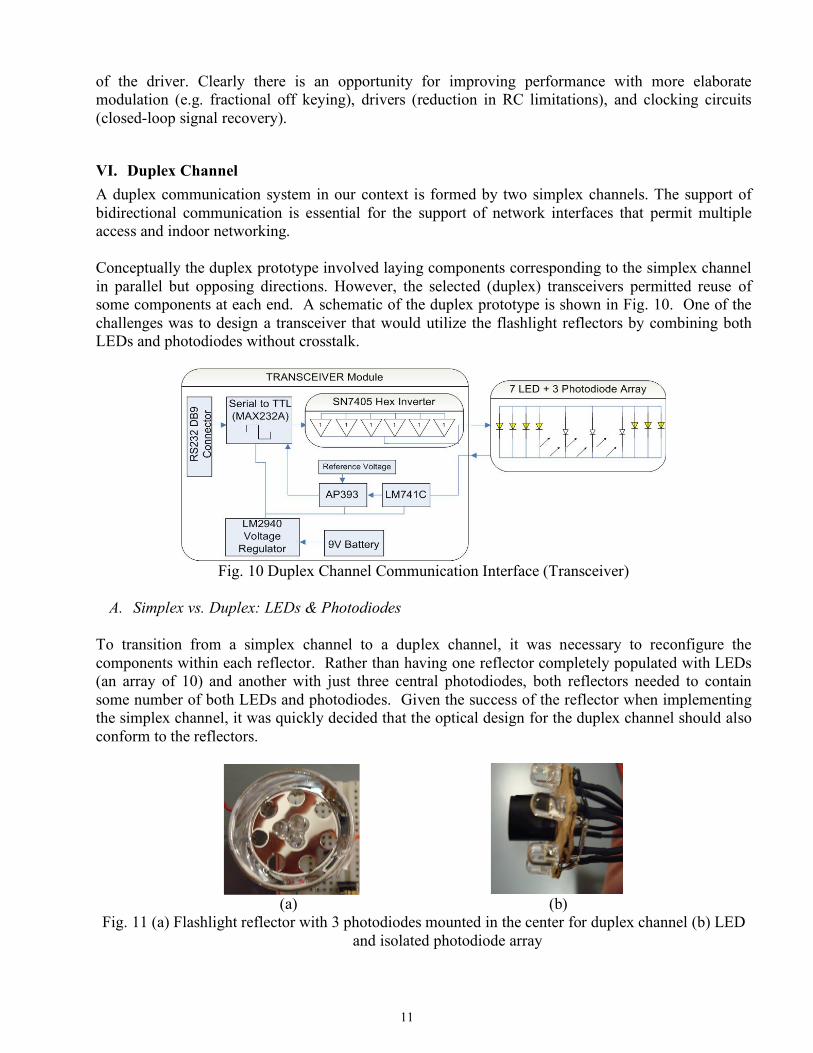
VI. Duplex Channel A duplex communication system in our context is formed by two simplex channels. The support of bidirectional communication is essential for the support of network interfaces that permit multiple access and indoor networking. Conceptually the duplex prototype involved laying components corresponding to the simplex channel in parallel but opposing directions. However, the selected (duplex) transceivers permitted reuse of some components at each end. A schematic of the duplex prototype is shown in Fig. 10. One of the challenges was to design a transceiver that would utilize the flashlight reflectors by combining both LEDs and photodiodes without crosstalk.
Fig. 10 Duplex Channel Communication Interface (Transceiver)
A. Simplex vs. Duplex: LEDs & Photodiodes
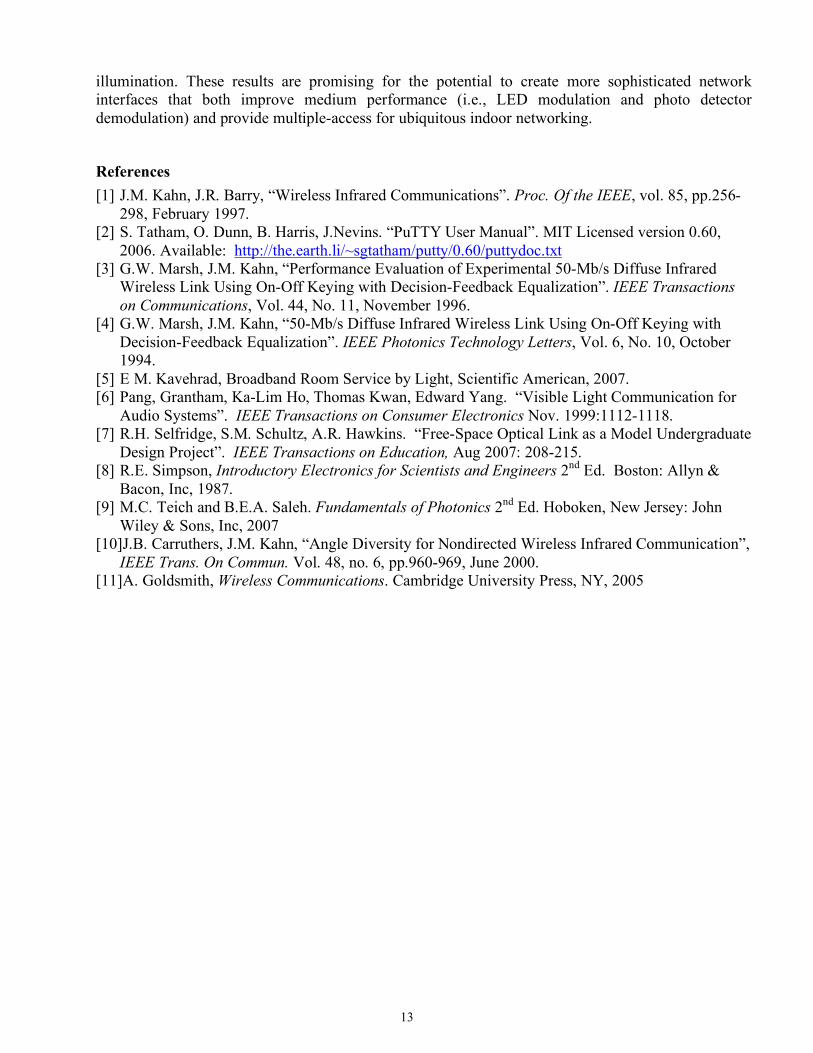
To transition from a simplex channel to a duplex channel, it was necessary to reconfigure the components within each reflector. Rather than having one reflector completely populated with LEDs (an array of 10) and another with just three central photodiodes, both reflectors needed to contain some number of both LEDs and photodiodes. Given the success of the reflector when implementing the simplex channel, it was quickly decided that the optical design for the duplex channel should also conform to the reflectors.
(a) (b)
Fig. 11 (a) Flashlight reflector with 3 photodiodes mounted in the center for duplex channel (b) LED and isolated photodiode array
12
Recall that the directionality of the photodiodes requires that they be aligned with the most intense portion of the incoming beam. Conversely, the light emanating from the LED’s diverges to create approximately uniform illumination. The circular arrangement of the LED’s within the reflector leads to the center of the beam having the highest intensity at some distance away from the source. These two physical considerations led to a duplex design where the two sides are identical, with 7 LED’s around the perimeter of the reflector and 3 photodiodes in the center. The LED’s could not easily be removed from the flashlight circuit, so independent LED’s were chosen and purchased.
B. Crosstalk In order to create a compact design we included both the transmit and the receive arrays on the same reflector that we used for the simplex channel. This led to the problem of crosstalk which affects our ability to receive data. In order, to reduce this problem we proceeded by wrapping the arrays of photodiodes with black electrical tape to reduce the effects of the local transmitter (Fig. 11 (b)). This setup was beneficial, however it did not completely isolate the photodiodes from crosstalk and the reflectors actually served to be detrimental. The oscilloscope plots are shown in Fig. 12.
(a) (b)
Fig. 12 (a) Crosstalk (b) No Crosstalk - Oscilloscope Outputs for duplex channel The first picture shows the effect of crosstalk with reflectors and the second image shows the received signal without the reflector. It can be seen on the crosstalk is more sever with the reflectors and this is because the reflected light by the local transmitter would also be recognized by the photodiodes at the small distances of separation that we were testing. Without the reflector the crosstalk is extremely diminished as shown in the figure on the left.
C. Results The full duplex circuits, based on their origin of the simplex design, were anticipated to have similar performance limitations. In practice, we observed lower data rates due to the limitations of the breadboard implementation. This configuration was inconclusive in terms of the noise introduced by the illumination component, the bidirectional crosstalk, and other potential effects.
VII. Summary This paper considers the opportunity provided by the replacement of existing illumination systems with LED-based lighting and the potential to introduce free-space optical networking with LED transceivers. We developed simplex and duplex transceiver prototypes as part our investigation and demonstrated their expected and achieved performance. In summary, using off-the-shelf LEDs and photodiodes we were able to demonstrate viable communication using visible light in the presence of normal room
13
illumination. These results are promising for the potential to create more sophisticated network interfaces that both improve medium performance (i.e., LED modulation and photo detector demodulation) and provide multiple-access for ubiquitous indoor networking.
References [1] J.M. Kahn, J.R. Barry, “Wireless Infrared Communications”. Proc. Of the IEEE, vol. 85, pp.256-
298, February 1997. [2] S. Tatham, O. Dunn, B. Harris, J.Nevins. “PuTTY User Manual”. MIT Licensed version 0.60,
Wireless Link Using On-Off Keying with Decision-Feedback Equalization”. IEEE Transactions on Communications, Vol. 44, No. 11, November 1996.
[4] G.W. Marsh, J.M. Kahn, “50-Mb/s Diffuse Infrared Wireless Link Using On-Off Keying with Decision-Feedback Equalization”. IEEE Photonics Technology Letters, Vol. 6, No. 10, October 1994.
[5] E M. Kavehrad, Broadband Room Service by Light, Scientific American, 2007. [6] Pang, Grantham, Ka-Lim Ho, Thomas Kwan, Edward Yang. “Visible Light Communication for
Audio Systems”. IEEE Transactions on Consumer Electronics Nov. 1999:1112-1118. [7] R.H. Selfridge, S.M. Schultz, A.R. Hawkins. “Free-Space Optical Link as a Model Undergraduate
Design Project”. IEEE Transactions on Education, Aug 2007: 208-215. [8] R.E. Simpson, Introductory Electronics for Scientists and Engineers 2nd Ed. Boston: Allyn &
Bacon, Inc, 1987. [9] M.C. Teich and B.E.A. Saleh. Fundamentals of Photonics 2nd Ed. Hoboken, New Jersey: John