International Academic Journal of Innovative Research International Academic Journal of Innovative Research Vol. 4, No. 3, 2017, pp. 10-21. ISSN 2454-390X 10 www.iaiest.com International Academic Institute for Science and Technology Using of the Vernier frequencies method to resolve problem of the ambiguity in range of the pulsed radars Reza Fatemi Mofradi a , Morteza Shahidi Nasab b a Department of Electrical and Electronic Engineering Malek Ashtar University of Technology, Tehran, Iran. b Master Student of electrical engineering malek ashtar University, Tehran, Iran. Abstract With the development of using of Doppler-pulse radars in the military and non-military industries, it is very important to increase accuracy and to eliminate annoying components in the process of data acquisition. Although various and useful methods have been provided by the forthcoming literatures in the world, a few studies have referred to increase accuracy in the decline and elimination of the nonconformity error between the range gate and the target-returned signal in the radar. By providing a modern and strong method, we are seeking to decline and eliminate this error. In the Vernier frequencies method, we will use three methods of using Vernier including the course size Vernier method, the average size Vernier method and the fine size Vernier method. With these three methods, we can suitably identify the amount of mentioned error and with the tracking gates, we can eliminate this error. In this paper, at first we will engage to introduce the Particle Filter method which eliminates the available ambiguities in the pulsed radars using of estimators and then in the following, we will analyze and investigate the Vernier frequencies method. Keywords: Vernier frequencies, Particle Filter, Pulse Doppler, High Pulse Repetition Frequency Introduction The main application of pulse Doppler radar to detect moving targets and find the range and speed as well. pulse Doppler radar are divided into three categories; Radar systems employ low, medium, and high PRF schemes. Low PRF waveforms can provide accurate, long, unambiguous range measurements, but exert severe Doppler ambiguities. Medium PRF waveforms must resolve both range and Doppler ambiguities; however, they provide adequate average transmitted power as compared to low PRFs. High PRF waveforms can provide superior average transmitted power and excellent clutter rejection capabilities [1-8]. Alternatively, high PRF waveforms are extremely ambiguous in range. When radar systems transmitted by Low pulse repetition frequency to detect and get the exact range is convenient but since the Nyquist
Transcript
International
Academic
Journal
of
Innovative Research International Academic Journal of Innovative Research
Vol. 4, No. 3, 2017, pp. 10-21.
ISSN 2454-390X
10
www.iaiest.com
International Academic Institute for Science and Technology
Using of the Vernier frequencies method to resolve problem
of the ambiguity in range of the pulsed radars
Reza Fatemi Mofradia, Morteza Shahidi Nasab
b
a Department of Electrical and Electronic Engineering Malek Ashtar University of Technology, Tehran, Iran.
b Master Student of electrical engineering malek ashtar University, Tehran, Iran.
Abstract
With the development of using of Doppler-pulse radars in the military and non-military industries, it is
very important to increase accuracy and to eliminate annoying components in the process of data
acquisition. Although various and useful methods have been provided by the forthcoming literatures in
the world, a few studies have referred to increase accuracy in the decline and elimination of the
nonconformity error between the range gate and the target-returned signal in the radar. By providing a
modern and strong method, we are seeking to decline and eliminate this error. In the Vernier frequencies
method, we will use three methods of using Vernier including the course size Vernier method, the
average size Vernier method and the fine size Vernier method. With these three methods, we can suitably
identify the amount of mentioned error and with the tracking gates, we can eliminate this error. In this
paper, at first we will engage to introduce the Particle Filter method which eliminates the available
ambiguities in the pulsed radars using of estimators and then in the following, we will analyze and
investigate the Vernier frequencies method.
Keywords: Vernier frequencies, Particle Filter, Pulse Doppler, High Pulse Repetition Frequency
Introduction
The main application of pulse Doppler radar to detect moving targets and find the range and speed as
well. pulse Doppler radar are divided into three categories; Radar systems employ low, medium, and high
PRF schemes. Low PRF waveforms can provide accurate, long, unambiguous range measurements, but
exert severe Doppler ambiguities. Medium PRF waveforms must resolve both range and Doppler
ambiguities; however, they provide adequate average transmitted power as compared to low PRFs. High
PRF waveforms can provide superior average transmitted power and excellent clutter rejection
capabilities [1-8].
Alternatively, high PRF waveforms are extremely ambiguous in range. When radar systems transmitted
by Low pulse repetition frequency to detect and get the exact range is convenient but since the Nyquist
International Academic Journal of Innovative Research,
Vol. 4, No. 3, pp. 10-21.
11
sampling rate when the repetition frequency is low, we do not observe it. Therefore, in determining the
speed targets will be ambiguous [9-13].
There are different methods to unambiguty the pulse Doppler radar, which is used in similar ways, but
the principles work in all manner of mathematical formulation of these methods is different.
The present methods to range ambiguity resolving mainly are signal processing methods and data
processing methods Data processing methods mainly are Chinese Remainder Theorem, permutation and
combination method, multiple hypothesis tracking (MHT) and so on [14-16].
The Chinese Remainder Theorem is simple and of low computation complexity, but it requires at least
three HPRFs and has the limitation that the numbers of range cells corresponding to HPRFs must be
coprime; the permutation and combination method and MHT method are of high computation
complexity; the hybrid filter and IMM methods perform well in range ambiguity resolving, but they do
not consider the clutter [12, 17].
Particle filer based method for target tracking with the HPRF radar in clutter. The method makes full use
of the particle filter (PF) that each particle represents a possible target state, updates target state with the
ambiguous measurement directly, and thus avoids the problem that each possible measurement must be
assigned a filter which may increase the computation complexity remarkably.
In the Vernier method, according to the condition of the target periphery, we seek to use one of the fine,
average and course methods. Using of these methods can help us to perceive larger the amount of error
between gate and the target-returned eco and to better resolve this error. this is like that we use a
magnifying glass to gather the pieces of glass. The stronger magnifying glass will cause to gather easier
the pieces of glass [8, 10, 15].
This paper proposed a Vernier frequency method for range unambiguty with the HPRF radar. The
proposed method makes full use of veriner frequency. Proposed method can solve range ambiguity and
target tracking in dense clutter simultaneously.
Particle Filter Method:
HPRF radar range ambiguity
Assume that maxR is the maximum range of interest, and , 1,2,...,r iF i L is the set of HPRFs
used for range ambiguity resolving. Without loss of generality, the i th HPRF , ,r iF is taken to formulate
the problem of HPRF radar range ambiguity. The maximum unambiguous range ,u iR corresponding
to ,r iF is given by
,
,
(1)2
u i
r i
CR
F
where C is the speed of light. As illustrated in Fig. 1, let , ( 1,2,..., )i kr i L denote the ambiguous
range measurement at time k. Then, all possible ranges are generated by
International Academic Journal of Innovative Research,
Vol. 4, No. 3, pp. 10-21.
12
, , ,( 1) , 1,2,..., ; 1,..., (2)
i k
ju i i k i
r R j r i L j P
with
max
,
, 1,2,..., (3)i
u i
RP floor i L
R
denoting the maximum unambiguous number. The function Floor(x) means to get the nearest integer less
than or equal to x. The value {1,2,..., }ij P is defined as the pulse interval number (PIN)
corresponding to HPRF ,r iF such that
,i k
jr reflects the true range of target at time k.
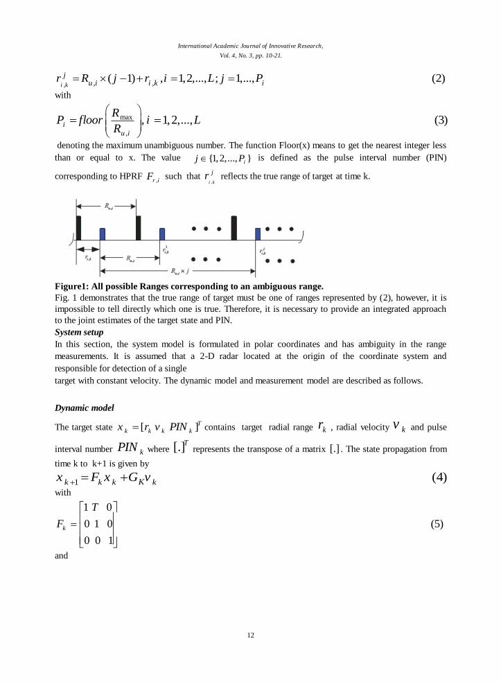
Figure1: All possible Ranges corresponding to an ambiguous range.
Fig. 1 demonstrates that the true range of target must be one of ranges represented by (2), however, it is
impossible to tell directly which one is true. Therefore, it is necessary to provide an integrated approach
to the joint estimates of the target state and PIN.
System setup In this section, the system model is formulated in polar coordinates and has ambiguity in the range
measurements. It is assumed that a 2-D radar located at the origin of the coordinate system and
responsible for detection of a single
target with constant velocity. The dynamic model and measurement model are described as follows.
Dynamic model
The target state [ ]Tk k k kx r v PIN contains target radial range kr , radial velocity kv and pulse
interval number kPIN where [.]T
represents the transpose of a matrix [.] . The state propagation from
time k to k+1 is given by
1(4)Kk k k k
x F x G v
with
1 0
0 1 0 (5)
0 0 1
k
T
F
and
International Academic Journal of Innovative Research,
Vol. 4, No. 3, pp. 10-21.
13
2
02
0 (6)
0 1
k
T
F T
respectively denoting the transition matrix and the distribution matrix of process noise, where T is the
sampling interval, and kv is a zero-mean white process noise with covariance
1
2
0(7)
0
qQ
q
Measurement Model
The measurement set is given by ,1 ,{ ,..., }
kk k k nZ z z , where kn is the number of measurements at
time k , and ( ) [ ( ) ( )]Tapp Dz k r k f k contains the apparent radial range and Doppler measurement.
The ambiguous measurement equation
at time k is given by
, ,, 1,..., (8)
k m k k i k kz H x W m n
Where
,1 0
(9)20 0
u i
k
R
H
is the measurement transitional matrix, is radar wavelength, , ,u iR is given by (1) and
kW is zero-
mean white Gaussian noise process of known covariance kR defined by
2
2
0(10)
0D
r
k
f
R
where 2
r and 2
Df are the range and Doppler measurement variance respectively.
Vernier frequency method
Using Vernier on the timing gates
The target range tracking systems operates based on range and then produce actual value of range for
tracked objectives, which should be calculated to launch and control missile on the scope of target.
Moreover, the target range tracking system operates the processing automatically to receive information
from external target and if it fails to operate and process this tracking, the automatic conduct of system
tracking is performed by using the range scan on the target.
International Academic Journal of Innovative Research,
Vol. 4, No. 3, pp. 10-21.
14
To perform tracking operation, the radar suggests three type of mode to us which include external target
allocation mode, local conduct mode and automatic tracking by the target-returned signal mode.
External target allocation mode and local conduct mode take priority over automatic tracking mode. The
external radar-allocated target range data which stored in the computer of system and then placed into the
integrator of tracking system is known the external target allocation mode.
Until the target allocation and determination data don’t perform operation of conduct with acceptable
accuracy, reformation on the target range determination system also will be performed by an operator.
Reformation will be done by a manual rotation or hand wheel.
Conduction must be done by observed image on the range- velocity monitor, when reformation is done
by an operator.
In case of accuracy of conduct on the target, the range tracking system should act in such a way that the
target is settled between the Range Mark domain and on the screen.
The local conduct mode engages to control the amount of range received from target allocation stage and
performs operation of conduct of range by a handwheel which can transfer range domain.
The range will be transferred regularly, until we change hand wheel. Amount of range is delivered to
semi-automatic tracking range device that when this system integrates from range coordinate, sends it to
automatic tracking range system.
This amount of range is delivered to the tracking system to implement the local conduct mode and the
speed of hand wheel rotation is main factor in the local conduct mode. Therefore, the measure of range
variations on the screen corresponds with the speed of variation and the handwheel rotation which be
entered to the tracking system.
The range sensor that is called manual wheel or hand wheel, can perform the range fine or course
reformation for tracking system.
In tracking mode, the target range error signal effects on the range determination system, which controls
and regulates the range- gate middle delay by ϕB, ϕH, Ʃ chanals.
basic principles of using Vernier
In first of this section, we will examine the basic principles and process of using Vernier with an example
and will verify finally our findings with a numerical example.
In the Vernier method, the pulse repetition frequency is selected in such a way that has smaller pulse
repetition periods compared with total time of signal emission and the target reception. Accordingly,
determination of range domain of target will arise ambiguity in range.
The ambiguity in range creates several problems for the target automatic tracking to choose a range
without ambiguity. Indeed, as soon as target moves, the pulses which returned by that are coincided and
corresponded with those signals observed in the periods corresponding to the ambiguous range and gated
pulses.
During emission, the receiver will be out of reach in order to prevent the returned signal.
The signals reflected from target do not receive at this time and the target tracking systems can't act
properly. In radar, advisable activities have been predicted to prevent this problem that its explanation
exceeds the topic of this section. To determine the amount of correct target range, the Vernier frequencies
method is implemented in radar. General principles of this method will be explained as follows.
International Academic Journal of Innovative Research,
Vol. 4, No. 3, pp. 10-21.
15
In this method, the pulses sent by radar, act periodically on two repetition frequencies. First is main
frequencies and another is selected among group is corresponded with modes that is multiples of main
frequency for having correct number of periodicity in Tunique period.
1 1 2 2 (11)uniqueT n PRI n PRI
Tunique is collective period in which the ambiguity in range will not to be existed.
In principles of tracking Vernier, we also will evaluate the average and course size Vernier method. We
will explain that the number of 1n and
2n periods, it is better to differ in unit size with each other in the
large size Vernier method that this causes to create the maximum amount of Tunique. This matter will be
verified by using of transactions as follows.
In this case, when the returned signals caused by main frequency are received with t1 delay, the pulses
caused through range gate are settled on the target-returned signals with t1 delay and will be corresponded
with returned signal too.
To explain the Vernier frequencies method which is to divide degrees by part, the timing diagram of
emitted pulses, the target-returned signals and gates of tracking will be examined and n values will be
selected to enhance understanding of this topic.
Figure 2 will describe this point by (n1=5, n2=4) values.
The a and b Figure 2 displays the received packets of pulses with repetition courses deals
1 2 1 21 2 1 2
1 1, ( , ) (12)u uT TT T T T
f f n n
In this figure, part c and part d will engage to represent the target-returned signals packages with t1 delay
in comparison to emitted pulses for both repetition frequencies.
Similarly, part e and part f engage to the range gate packages which is settled on the target-returned
signals with t1 delay in comparison to the emitted pulses and these parts lead to gate the signals returned
by target.
Also, h and g diagrams of this figure focus on packages of the same range gates with t1+T1 delay, that is,
they advance the returned range gate of the T1 size and is placed exactly on the gated signal. Then, the
gate order will be shifted of the T1 size, which caused by second signal, that is mean, gating of both is
done from same point and they are overlapped in the especial multiple; that point will be the unambiguity
range of our target.
Hence, it can be inferred that we should fix error and difference rate between the target-returned signals
through delaying the range gate.
If one error resulted from deviation between the actual range of target and the range is gained by gating,
take places during a frequency period, transferring to other frequencies will cause to mismatch between
gates and the target-returned signals the Δ dimension.
Δ is the time difference between the range gates adjusted in the repetition period of T1 and the target-
returned signals in the repetition period of T2.
1 2
2 1 1 2 1 2
(13)* *
u u u u uT T nT n T T
n n n n n n
That is, in equation (18) in direct dependency with the uT as well.
In cases where the error is the size of K period 1T , relation (14) will be established.
International Academic Journal of Innovative Research,
Vol. 4, No. 3, pp. 10-21.
16
1 2
* (14)uTK
n n
Therefore, determination of unambiguous range of target will be done when Δ= 0. In this case, two
returned signals will be overlapped in one space and that point will be position of unambiguous range.
To increase the sensitivity of the Vernier frequencies method and the mobility of the target marks on the
different repetition frequencies, in addition to large scale, an important scale also is employed by using
major and minor frequency to make a difference between n values of more than unity size which is equal
to a greater integer and (n1-n3)= N.
In this case, the existence of an error in the single range determination will enable us to decrease the
greatest amount of unambiguous range of the N size.
So, other measures are used to determine total of uniform range.
To facilitate the process, the measure which is corresponded to the middle single range (T'0) is considered
as average measure and the measure is used as the course measure which employed to determine all of
uniform ranges.
We have to establish the following conditions, if we tend to use the Vernier frequencies method:
0, , (15)2
o o
o
T T mm N
T T
Where T'0 is period of new unambiguous range and T0 indicates total unambiguous range and N is also an
integer.
In this equation, m indicates the tenth decimal which obtained after dividing and equals m< 1.
In the total of covered domain, if amount of unambiguous range be greater than amount of the average
single range in the 1
m quantity, then the adopted frequency period will be satisfaction based on the
following conditions:
Interval of new unambiguous range T'0 should include integer (N) of T periods and the remaining period
must be equal 2
m.
International Academic Journal of Innovative Research,
Vol. 4, No. 3, pp. 10-21.
17
a
b
c
d
e
f
g
h
unambT
1T
2T
1t
1t
1 1t T
unambT
unambT unambT unambT
T 2 3
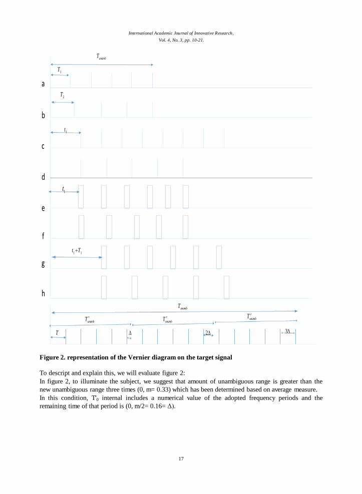
Figure 2. representation of the Vernier diagram on the target signal
To descript and explain this, we will evaluate figure 2:
In figure 2, to illuminate the subject, we suggest that amount of unambiguous range is greater than the
new unambiguous range three times (0, m= 0.33) which has been determined based on average measure.
In this condition, T'0 internal includes a numerical value of the adopted frequency periods and the
remaining time of that period is (0, m/2= 0.16= Δ).
International Academic Journal of Innovative Research,
Vol. 4, No. 3, pp. 10-21.
18
By this diagram, it can be concluded that the mismatch between gate and the returned signal is great and a
great error will be happened in determination of range based on average measure.
If an error is happened in a distance, then the mismatch between gate and signal is 0.16 of period
(m/2= 0.16) or (0.16* T) and maximum error will be (3×0.16≈0.5) due to repetition of three of 0T
intervals in T0 interval.
Accordingly, similar to fine and average Vernier methods it is necessary to create a mismatch (Δ=0) to
determine the general unambiguous range. In this case, the requested gate delay is regulated in the stairs
of multiples of the main frequency period.
The process of the target unambiguous range determination is operated in the controlled chanal and it can
be used for modes of conduct of systems and the target tracking.
In the Vernier method, we will study based on the average and coarse measures. In the coarse measure,
the difference between n values equals one but in the average measure, this difference is two.
When the difference between n values is more than unit, the unambiguous range is decreased according
the difference of n values and the error rate will be greater.
We apply the average method to increase accuracy in the operation of decline in the error of gate and the
returned signal.
Here, we will examine the Vernier method for small periods because this method should be analyzed in
the system tracking discussion and in this section, we will represent only one example of how the system
operates.
As mentioned in the previous section, we will have two periods as follows:
1
2
1 1 2 2
1 2
1
1
2
2
10
12
(16)
6, 5
6
5
(6)(10) (5)(12) 60
unique
u u
u u
unique
T
T
T n PRI n PRI
n n
T TT
n
T TT
n
T
Since the difference between n1 and n2 is of the unity size, so we have used the course Vernier which will
have the greatest unambiguous range in 60.
Equation (12) will show that if we have one error period, the difference between the range gates regulated
on the target in the repetition period T1 and the target-returned signals in the repetition period T2 will be
2.
1 2
2 1 1 2 1 2* *
60 60 6(60) 5(60) 602 (17)
5 6 (5)(6) 30
u u u u uT T nT n T T
n n n n n n
International Academic Journal of Innovative Research,
Vol. 4, No. 3, pp. 10-21.
19
But if we have the error in the several periods, the difference between the range gates regulated in the
repetition period T1 and the target-returned signals in the repetition period T2 will be equation (18):
1 2
60* * 2 (18)
* 30
uTK K k k
n n
We will use one example to finely illustrate this matter.
According to figure (2), we send two minor and major pulses and receive the signals returned by part a in
the part c and the pulses returned by part b in the part d.
In this case, the returned signals are received with t1 delay, which resulted from the minor and major
frequencies, therefore the pulses that created by the range gate with t1 delay will be settled on the target-
returned signals and corresponded to the returned signals.
This will be happened in the part e and part f. In the part g and part h, we engage to the pulse delay of the
range gate of the t1+T1 size, when the difference between n values is equal unit because when we shift the
pulse e of the T1 size, that is means we shift the range gate of the T1 size and this range gate is settled
exactly on the signal. Then, we advance the gate order that resulted from second signal of the T1 size and
this means that the gating of both is done from same point and they are overlapped on the especial and
common multiple and this point will be our unambiguous range of target.
This means that we must fix the error which resulted from mismatch of the target signal in the T1
frequency period with the range gate caused from the T2 frequency period.
1
2
10 0 10 20 30 40 50 70 80 90 100 110 120 140 150
12 0 12 24 36 48 72 84 96 108 120 130 ...
10 22 34 46 58 70 82 94 106 118 ...
12 10 2 1
60 130
60
130
first period
for T
for T
K first period
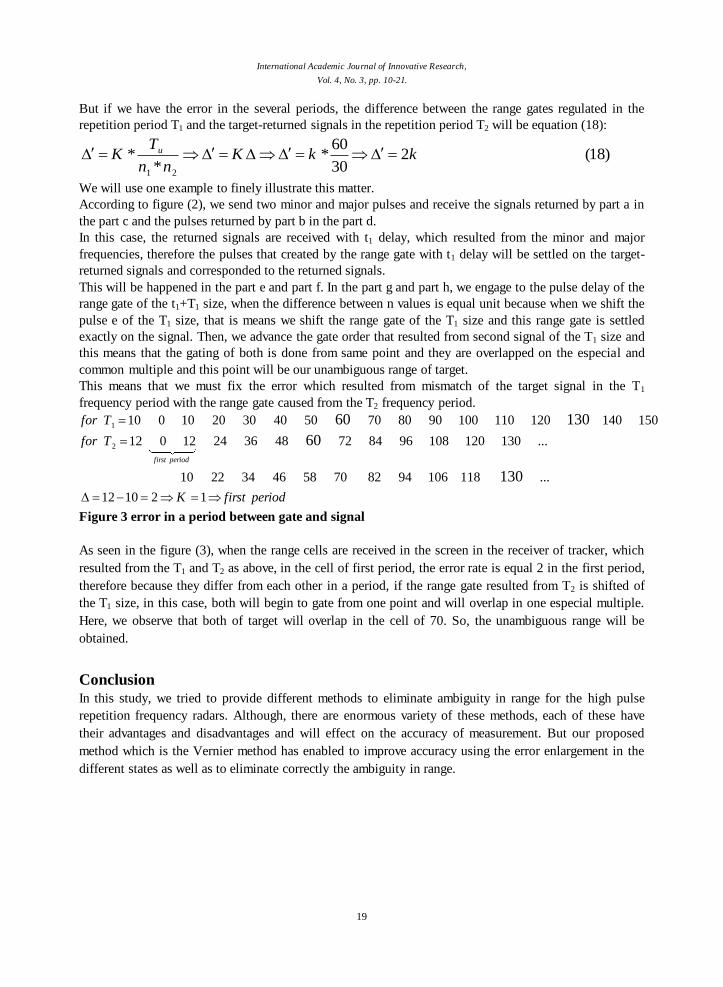
Figure 3 error in a period between gate and signal
As seen in the figure (3), when the range cells are received in the screen in the receiver of tracker, which
resulted from the T1 and T2 as above, in the cell of first period, the error rate is equal 2 in the first period,
therefore because they differ from each other in a period, if the range gate resulted from T2 is shifted of
the T1 size, in this case, both will begin to gate from one point and will overlap in one especial multiple.
Here, we observe that both of target will overlap in the cell of 70. So, the unambiguous range will be
obtained.
Conclusion
In this study, we tried to provide different methods to eliminate ambiguity in range for the high pulse
repetition frequency radars. Although, there are enormous variety of these methods, each of these have
their advantages and disadvantages and will effect on the accuracy of measurement. But our proposed
method which is the Vernier method has enabled to improve accuracy using the error enlargement in the
different states as well as to eliminate correctly the ambiguity in range.
International Academic Journal of Innovative Research,
Vol. 4, No. 3, pp. 10-21.
20
References
[1] D. C. Schlher,MTI and Pulsed Doppler Radar, Noorwood, MA: Artech House, 19913. m.staudaher,