27
| Date post: | 08-Apr-2018 |
| Category: |
Documents |
| Upload: | adam-ahmad |
| View: | 255 times |
| Download: | 3 times |

8/7/2019 Vehicle Starting System
http://slidepdf.com/reader/full/vehicle-starting-system 1/27

8/7/2019 Vehicle Starting System
http://slidepdf.com/reader/full/vehicle-starting-system 2/27
Vehicle Starting SystemVehicle Starting System
The "starting system", the heart of the electricalThe "starting system", the heart of the electricalsystem in the car, begins with the BATTERY.system in the car, begins with the BATTERY.
The key is inserted into the IGNITION SWITCHThe key is inserted into the IGNITION SWITCHand then turned to the start position.and then turned to the start position.
A small amount of current then passes through theA small amount of current then passes through theNEUTRAL SAFETY SWITCH NEUTRAL SAFETY SWITCH to ato a STARTER STARTER SOLENOIDSOLENOID which allows high current to flowwhich allows high current to flowthrough thethrough the BATTERY CABLESBATTERY CABLES to theto the STARTERSTARTERMOTORMOTOR..
The starter motor then cranks the engine so thatThe starter motor then cranks the engine so thatthe piston moving downward,the piston moving downward,
±± Create a suction or vacuum that will draw aCreate a suction or vacuum that will draw a
Fuel/Air Fuel/Air mixture into the cylinder, where amixture into the cylinder, where aspark created by the IGNITION SYSTEM willspark created by the IGNITION SYSTEM willignite this mixture.ignite this mixture.
If theIf the CompressionCompression in the engine is high enoughin the engine is high enoughand all this happens at the rightand all this happens at the right TimeTime, the engine, the enginewill start.will start.
8/7/2019 Vehicle Starting System
http://slidepdf.com/reader/full/vehicle-starting-system 3/27
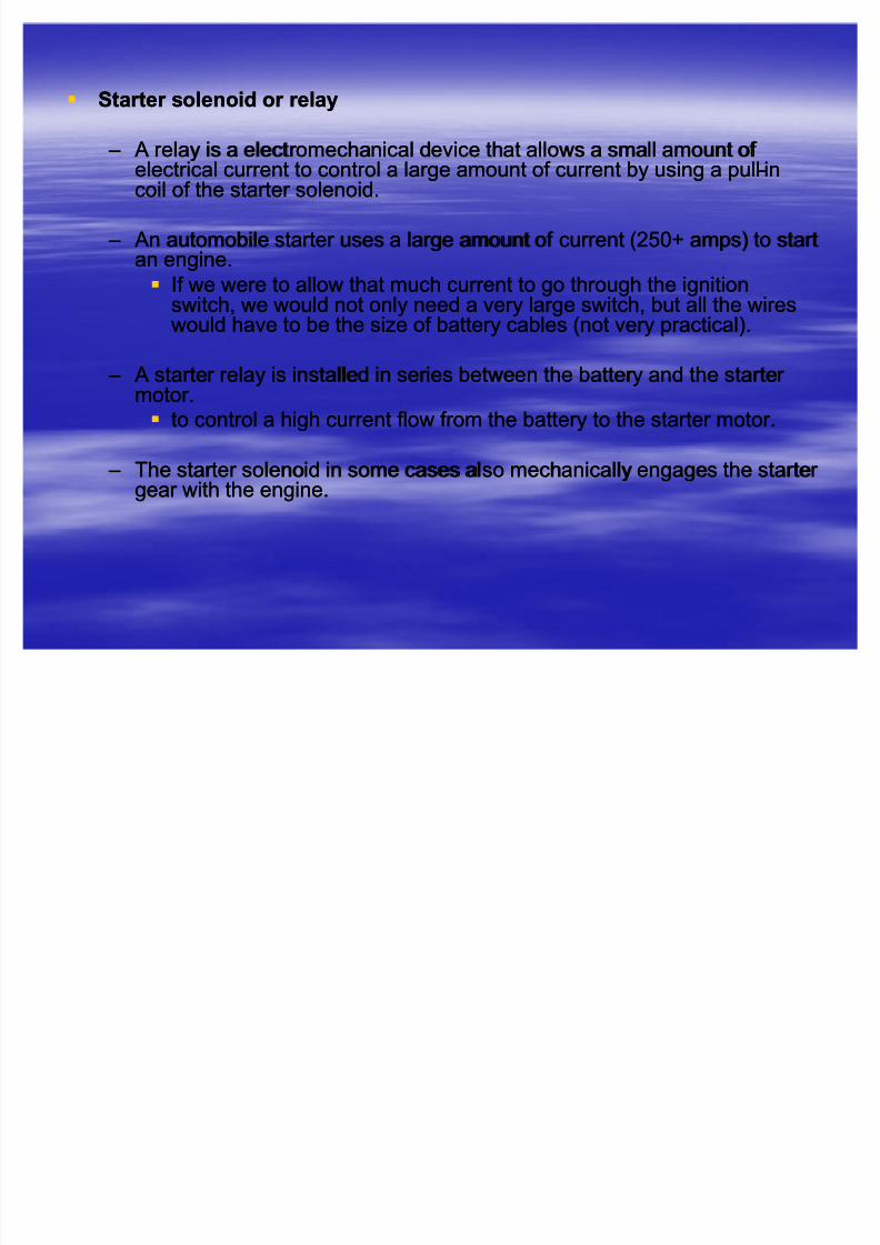
Star ter solenoid or relayStar ter solenoid or relay
±± A relay is a electromechanical device that allows a small amount of A relay is a electromechanical device that allows a small amount of electrical current to control a large amount of current by using a pullelectrical current to control a large amount of current by using a pull--inincoil of the starter solenoid.coil of the starter solenoid.
±± An automobile starter uses a large amount of current (250+ amps) to startAn automobile starter uses a large amount of current (250+ amps) to startan engine.an engine.
If we were to allow that much current to go through the ignitionIf we were to allow that much current to go through the ignition
switch, we would not only need a very large switch, but all the wiresswitch, we would not only need a very large switch, but all the wireswould have to be the size of battery cables (not very practical).would have to be the size of battery cables (not very practical).
±± A starter relay is installed in series between the battery and the starter A starter relay is installed in series between the battery and the starter motor.motor.
to control a high current flow from the battery to the starter motor.to control a high current flow from the battery to the starter motor.
±± The starter solenoid in some cases also mechanically engages the starter The starter solenoid in some cases also mechanically engages the starter gear with the engine.gear with the engine.

8/7/2019 Vehicle Starting System
http://slidepdf.com/reader/full/vehicle-starting-system 4/27
Control circuit
Magneticsolenoid
switch
Flywheel
S. gear

8/7/2019 Vehicle Starting System
http://slidepdf.com/reader/full/vehicle-starting-system 5/27
Star ter Motor Star ter Motor
±± The starter motor is a powerful electric motor, with a small gear (pinion)The starter motor is a powerful electric motor, with a small gear (pinion)
attached to the larger gear of the engine.attached to the larger gear of the engine.
±± When activated, the gear is meshed with a larger gear (ring), which isWhen activated, the gear is meshed with a larger gear (ring), which is
attached to the engine.attached to the engine.
±± The starter motor then spins the engine over so that the piston can draw inThe starter motor then spins the engine over so that the piston can draw in
a fuel/ air mixture, which is then ignited to start the engine.a fuel/ air mixture, which is then ignited to start the engine.
±± When the engine starts to spin faster than the starter, a device called anWhen the engine starts to spin faster than the starter, a device called an
overrunning clutch (bendix drive) automatically disengages the starter overrunning clutch (bendix drive) automatically disengages the starter
gear from the engine gear.gear from the engine gear.

8/7/2019 Vehicle Starting System
http://slidepdf.com/reader/full/vehicle-starting-system 6/27
Requirements of the Starting SystemRequirements of the Starting System
±± Engine starting requirementsEngine starting requirements
An internal combustion engine requires the following criteria to start andAn internal combustion engine requires the following criteria to start and
continue running:continue running:±± A/F mixture during intake strokeA/F mixture during intake stroke
±± Combustion stroke/power strokeCombustion stroke/power stroke
±± Form of ignitionForm of ignition
±± Starting speedStarting speed
It is noted that in order to produce the first three of the above conditions,It is noted that in order to produce the first three of the above conditions,
the enginethe engine minimum start ing speed minimum start ing speed of 100 rev/min must be achieved.of 100 rev/min must be achieved.
The ability to reach theThe ability to reach the minimum speed minimum speed is dependent on a number of is dependent on a number of following factors:following factors:
±± Rated voltage of the starting systemRated voltage of the starting system
±± Torque requirement of cr anking the engineTorque requirement of cr anking the engine
±± Voltage drop between the battery and the starter Voltage drop between the battery and the starter
±± Star ter Star ter--toto--ring gear r atioring gear r atio
±± Cranking speed of the engine, but if Cranking speed of the engine, but if
Intake stroke will be inIntake stroke will be in--completedcompleted
Lack of A/F mixture in the combustion chamber Lack of A/F mixture in the combustion chamber
The engine will not start.The engine will not start.

8/7/2019 Vehicle Starting System
http://slidepdf.com/reader/full/vehicle-starting-system 7/27
Vehicle Starting SystemVehicle Starting System--continuecontinue
Lighting andother system
Charging system
Starter motor
Ignition switch Starter Relay
Battery
Engine
Ignition system
Ignition module

8/7/2019 Vehicle Starting System
http://slidepdf.com/reader/full/vehicle-starting-system 8/27
Starting system circuitsStarting system circuits
±± Starting system draw a large amount of current from the batteryStarting system draw a large amount of current from the batteryto power the starter motor.to power the starter motor.
To handle this current safely and with a minimum voltage loss fromTo handle this current safely and with a minimum voltage loss fromresistanceresistance
±± The cable must be correct sizeThe cable must be correct size
±± If the heavy cables that carry current,If the heavy cables that carry current,
The starter would not get enough current to operate properly.The starter would not get enough current to operate properly.
To avoid such a voltage drop, two basic circuits are normallyTo avoid such a voltage drop, two basic circuits are normallyemployed for the starting system:employed for the starting system:
Starter circuitStarter circuit
Control circuitControl circuit
Control circuitControl circuit
±± It allows the driver to use a small amount of battery currentIt allows the driver to use a small amount of battery current
About 3 to 5 ampAbout 3 to 5 amp
To control the flow of large amount of battery current to the starter To control the flow of large amount of battery current to the starter motor.motor.
±± Control circuit usually consist of an ignition switch connected to theControl circuit usually consist of an ignition switch connected to the
Battery and magnetic switchBattery and magnetic switch

8/7/2019 Vehicle Starting System
http://slidepdf.com/reader/full/vehicle-starting-system 9/27
Control circuit
Magneticsolenoid
switch
Flywheel
S. gear
Starter circuit

8/7/2019 Vehicle Starting System
http://slidepdf.com/reader/full/vehicle-starting-system 10/27
±± When the ignition switch is in the startWhen the ignition switch is in the start
position,position, A small amount of current flows through the coil of A small amount of current flows through the coil of
the magnetic switchthe magnetic switch
This closes a set of large contact points within theThis closes a set of large contact points within themagnetic switch and allows battery current to flowmagnetic switch and allows battery current to flow
directly to the starter motor.directly to the starter motor.
±± Magnetic switchMagnetic switch Allows the control circuit to open and close theAllows the control circuit to open and close the
starter circuit.starter circuit.
±± A relay, which uses the electromagnetic field of a coil toA relay, which uses the electromagnetic field of a coil toattract an armature and close the contact points.attract an armature and close the contact points.
±± A solenoid, which uses the electromagnetic field of a coilA solenoid, which uses the electromagnetic field of a coilto pull in plunger into the coil and close the contactto pull in plunger into the coil and close the contactpoints.points.

8/7/2019 Vehicle Starting System
http://slidepdf.com/reader/full/vehicle-starting-system 11/27
Starter system designStarter system design
±± Starter system design requirements:Starter system design requirements:
Rated voltageRated voltage
±± Passenger car:12vPassenger car:12v
±± Truck and buses :24vTruck and buses :24v Voltage dropVoltage drop
±± Consider the wire size and lengthConsider the wire size and length
Limiting temperatureLimiting temperature
±± Passenger car:Passenger car: --18c to18c to --25c25c
±± Truck and buses:Truck and buses:--15c to 20c15c to 20c
Rated output power Rated output power
±± A battery maximum capacity for the starter 20% drop atA battery maximum capacity for the starter 20% drop at --20c temperature when it is20c temperature when it isconnected to a starter by a cable with a resistance of 1mohmconnected to a starter by a cable with a resistance of 1mohm
This criteria will ensure the starter is able to operate even under the mostThis criteria will ensure the starter is able to operate even under the mostadverse condition.adverse condition.
Therefore, a good conductor cable is the best choice to select for the starter Therefore, a good conductor cable is the best choice to select for the starter cable.cable.
Engine torque requirementEngine torque requirement
±± A greater torque is required for engines with a lower number of cylinders due to theA greater torque is required for engines with a lower number of cylinders due to the
greater piston displacement (as the volumetric efficiency,greater piston displacement (as the volumetric efficiency,±± Stalled torqueStalled torque
Under the worst condition (Under the worst condition (--20c), a four cylinder 220c), a four cylinder 2 litrelitre engine requires 480Nmengine requires 480Nmto overcome static friction and 160Nm to maintain the minimum cranking speedto overcome static friction and 160Nm to maintain the minimum cranking speedof 100 rev/min.of 100 rev/min.
Lowest possible size and weightLowest possible size and weight

8/7/2019 Vehicle Starting System
http://slidepdf.com/reader/full/vehicle-starting-system 12/27
Choosing a starter motor Choosing a starter motor
±± Starter motor torque could be determined from the typical starter torque and engine crankingStarter motor torque could be determined from the typical starter torque and engine crankingtorque curve.torque curve.
±± Power rating of the motor have to be quoted atPower rating of the motor have to be quoted at --20c temperature for the recommended20c temperature for the recommended
battery.battery.±± Greater torque is required for engines with lower number of cylinders due to the greater Greater torque is required for engines with lower number of cylinders due to the greater
piston displacement per cylinder piston displacement per cylinder
For example: A four cylinder 2 litre engine requires 480Nm to overcome the staticFor example: A four cylinder 2 litre engine requires 480Nm to overcome the staticfriction and 160Nm to maintain the minimum cranking speed of 100 rev/min.friction and 160Nm to maintain the minimum cranking speed of 100 rev/min.
±± If the motor torque is very low but engine torque requirement during starting is high, what typeIf the motor torque is very low but engine torque requirement during starting is high, what typeof mechanism should consider to develop the required torque.of mechanism should consider to develop the required torque.
±± A typical cranking current for a light weight vehicle engine is 150A. But, the peak crankingA typical cranking current for a light weight vehicle engine is 150A. But, the peak crankingcurrent for adverse condition could be 500 A.current for adverse condition could be 500 A.
±± Maximum voltage drop 0.5 V should be allowed between the battery and the starter whenMaximum voltage drop 0.5 V should be allowed between the battery and the starter whenoperating.operating.
±± Based on the voltage drop, the resistance of the cable must be 2.5 mBased on the voltage drop, the resistance of the cable must be 2.5 m--ohm when the supplyohm when the supplyvoltage 12 v is considered.voltage 12 v is considered.

8/7/2019 Vehicle Starting System
http://slidepdf.com/reader/full/vehicle-starting-system 13/27
How ??

8/7/2019 Vehicle Starting System
http://slidepdf.com/reader/full/vehicle-starting-system 14/27
Star ting motor and circuitsStar ting motor and circuits
±± The starter is usually operated by a spring loaded key switchThe starter is usually operated by a spring loaded key switch The supply from the key switch via a relay causes the starter solenoidThe supply from the key switch via a relay causes the starter solenoid
to operate by a set of contacts.to operate by a set of contacts. The problem of voltage drop in the main supply circuit is due to theThe problem of voltage drop in the main supply circuit is due to the
high current required by the starter high current required by the starter
±± Particularly under adverse starting conditions such as very lowParticularly under adverse starting conditions such as very lowtemperature.temperature.
±± It is generally accepted that a maximum volt drop of only 0.5vIt is generally accepted that a maximum volt drop of only 0.5vshould be allowed between the battery and starter whenshould be allowed between the battery and starter whenoperatingoperating
A typical cranking current for a light vehicle engine in continuousA typical cranking current for a light vehicle engine in continuousloading 150A.loading 150A.
±± But, this may peak in excess of 500A to provide the initial stalledBut, this may peak in excess of 500A to provide the initial stalledtorque.torque.
±± By using Ohm¶s law calculation indicates that the maximumBy using Ohm¶s law calculation indicates that the maximumallowed circuit resistance is 2.5mohm when using a 12V supply.allowed circuit resistance is 2.5mohm when using a 12V supply.
±± The choice of suitable conductor is therefore very important.The choice of suitable conductor is therefore very important.

8/7/2019 Vehicle Starting System
http://slidepdf.com/reader/full/vehicle-starting-system 15/27
Theory of the DC motor:Theory of the DC motor:
±± If the shaft of a DC motor is turned by an external force, the motor will actIf the shaft of a DC motor is turned by an external force, the motor will actlike a generator and produce an electric motive force (EMF).like a generator and produce an electric motive force (EMF).
±± Typically a motor takes power in the form of voltage and current andTypically a motor takes power in the form of voltage and current andconverts the energy into mechanical energy in the form of rotation.converts the energy into mechanical energy in the form of rotation.
Most motors can be generators by just spinning the motor and lookingMost motors can be generators by just spinning the motor and lookingfor a voltage/current on the motor windings.for a voltage/current on the motor windings.
The motor is run almost continually as a motor with current beingThe motor is run almost continually as a motor with current beingsupplied to the turn of the windings.supplied to the turn of the windings.

8/7/2019 Vehicle Starting System
http://slidepdf.com/reader/full/vehicle-starting-system 16/27
±± The spinning of the motor produces a voltage known as the backThe spinning of the motor produces a voltage known as the backEMF because it opposes the applied voltage on the motor.EMF because it opposes the applied voltage on the motor.
BackBack--EMF refers to using the voltage generated by a spinningEMF refers to using the voltage generated by a spinningmotor or the speed of the motor's rotation.motor or the speed of the motor's rotation.
In a motor using a rotating armature and, in the presence of aIn a motor using a rotating armature and, in the presence of amagnetic fluxmagnetic flux, the conductors cut the magnetic field lines as they, the conductors cut the magnetic field lines as theyrotate.rotate.
±± The changing field strength produces a voltage in the coil.The changing field strength produces a voltage in the coil.((Faraday's law of inductionFaraday's law of induction.).)
±± This voltage opposes the original applied voltage; therefore,This voltage opposes the original applied voltage; therefore,it is called "it is called "counter counter--elec tr omot iv eelec tr omot iv e f or c ef or c e³or ³or backback emf emf. (by. (byLenz's lawLenz's law.).)
±± Therefore, the voltage drop across a motor consists due to the backTherefore, the voltage drop across a motor consists due to the back
EMF and the parasitic voltage drop resulting from the internalEMF and the parasitic voltage drop resulting from the internalresistance of the motor windings. The current through a motor isresistance of the motor windings. The current through a motor isgiven by the equation:given by the equation:
R
eV I
!

8/7/2019 Vehicle Starting System
http://slidepdf.com/reader/full/vehicle-starting-system 17/27
±± Since the back EMF is proportional to motor speed,Since the back EMF is proportional to motor speed,
when an electric motor is first started or is completely stalled,when an electric motor is first started or is completely stalled,there is zero back EMF.there is zero back EMF.
±± QuestionQuestion --why?why?
Therefore the current through the apparatus is much higher.Therefore the current through the apparatus is much higher.
±± This high current will produce a strong electromagnetic fieldThis high current will produce a strong electromagnetic field
which will start the motor spinning.which will start the motor spinning.
±± As the motor spins, the back EMF increases until it is equalAs the motor spins, the back EMF increases until it is equal
to the applied voltage minus the parasitic voltage drop.to the applied voltage minus the parasitic voltage drop.
±± At this point there will be a smaller current flowing throughAt this point there will be a smaller current flowing through
the motor. Basically the following three equations can bethe motor. Basically the following three equations can be
used to find the speed, and back EMF of a motor under aused to find the speed, and back EMF of a motor under aload:load:

8/7/2019 Vehicle Starting System
http://slidepdf.com/reader/full/vehicle-starting-system 18/27
Difference between motor and generator:Difference between motor and generator:
±± A motor takes power in the form of voltage andA motor takes power in the form of voltage and
current and converts the energy into mechanicalcurrent and converts the energy into mechanicalenergy in the form of rotation.energy in the form of rotation.
±± A generator takes mechanical energy andA generator takes mechanical energy and
converts it into both electrical energy with aconverts it into both electrical energy with a
voltage and current.voltage and current.

8/7/2019 Vehicle Starting System
http://slidepdf.com/reader/full/vehicle-starting-system 19/27
For DC motor the back EMF is given by:For DC motor the back EMF is given by:
i,e., the µn¶ of the motor will be proportional to the ratio of flux to emf as thei,e., the µn¶ of the motor will be proportional to the ratio of flux to emf as the
parameters p,Z, c in the above equations are constant.parameters p,Z, c in the above equations are constant.
winding waveafor or winding lappc
conductor armatur eof NoZ
rpsnpair pol enumberof pwher e
cnZ pe
22
,.
,,,
2
!
!
!!
! J
waveper Fluxwher e
e
n
!
w
J
J
,

8/7/2019 Vehicle Starting System
http://slidepdf.com/reader/full/vehicle-starting-system 20/27
Star ter motor (DC motor) Oper ational principle

8/7/2019 Vehicle Starting System
http://slidepdf.com/reader/full/vehicle-starting-system 21/27
Starter motor (DC motor)Starter motor (DC motor)
±± Two basic circuits are in any DC motor: theTwo basic circuits are in any DC motor: the
armature (the device that rotates, sometimesarmature (the device that rotates, sometimesreferred to as areferred to as a r ot or r ot or ) and the field (the) and the field (the
stationary part, sometimes referred to as astationary part, sometimes referred to as a
stat or stat or ).).
The two components magnetically interact with oneThe two components magnetically interact with oneanother to produce rotation in the armature.another to produce rotation in the armature.

8/7/2019 Vehicle Starting System
http://slidepdf.com/reader/full/vehicle-starting-system 22/27
Electric motor Electric motor
±± AnAn electric motor electric motor convertsconverts electrical energyelectrical energy into kineticinto kineticenergy.energy.
±± Oper ationOper ation
Most electric motors work byMost electric motors work by electromagnetismelectromagnetism,,
The fundamental principle upon which electromagnetic motors are based isThe fundamental principle upon which electromagnetic motors are based is
that there is athat there is a mechanical forcemechanical force on any currenton any current--carrying wire containedcarrying wire contained
within a magnetic field.within a magnetic field.
The force is described by theThe force is described by the Lorentz force lawLorentz force law and is perpendicular to bothand is perpendicular to both
the wire and the magnetic field.the wire and the magnetic field.
±± Starter DC motor: the rotating part (usually on the inside) is called theStarter DC motor: the rotating part (usually on the inside) is called the
rotor rotor , and the stationary part is called the, and the stationary part is called the stator stator ..
±± The rotor rotates because the wires and magnetic field are arranged soThe rotor rotates because the wires and magnetic field are arranged sothat athat a torquetorque is developed about the rotor's axis.is developed about the rotor's axis.
±± The motor containsThe motor contains electromagnetselectromagnets that are wound on a armature.that are wound on a armature.
±± The armature is that part of the motor across which the inputThe armature is that part of the motor across which the input voltagevoltage isis
supplied.supplied.
±± Depending upon the design of the machine, either the rotor or the stator Depending upon the design of the machine, either the rotor or the stator
can serve as the armature.can serve as the armature.

8/7/2019 Vehicle Starting System
http://slidepdf.com/reader/full/vehicle-starting-system 23/27
The force on the conductor is developed due to the interaction of theThe force on the conductor is developed due to the interaction of the
main magnetic field and the field created around the conductor.main magnetic field and the field created around the conductor.
The strength of the magnetic field is determined by the value of theThe strength of the magnetic field is determined by the value of the
current flowing (eddy current).current flowing (eddy current).
Starter motor designs use a four Starter motor designs use a four--pole four brush.pole four brush.±± Using the four poles concentrates magnetic field the motor is operated.Using the four poles concentrates magnetic field the motor is operated.
Engine Not Starting? Need Help Now?

8/7/2019 Vehicle Starting System
http://slidepdf.com/reader/full/vehicle-starting-system 24/27
When the current flows through a conductor placed in a magneticWhen the current flows through a conductor placed in a magneticfieldfield
±± A force will be created acting on the conductor relative to the field.A force will be created acting on the conductor relative to the field.
±± The magnitude of this force is perpendicular to the field strength, theThe magnitude of this force is perpendicular to the field strength, thelength of the conductor in the field and the current flowing in thelength of the conductor in the field and the current flowing in theconductor conductor
In DC motor, the single conductor is of no practical useIn DC motor, the single conductor is of no practical use
±± The conductor is shaped into a loop or many loops to form the armatureThe conductor is shaped into a loop or many loops to form the armature
Answer : what will happen the output voltage if only a single loop is used as aAnswer : what will happen the output voltage if only a single loop is used as aconductor in the magnetic field of a DC motor.conductor in the magnetic field of a DC motor.
±± A many segment commutator allows contact via brushes to the supplyA many segment commutator allows contact via brushes to the supplycurrentcurrent

8/7/2019 Vehicle Starting System
http://slidepdf.com/reader/full/vehicle-starting-system 25/27
±± Figure 1 shows that when the coil is powered, a magnetic field isFigure 1 shows that when the coil is powered, a magnetic field isgenerated around the armature.generated around the armature.
The left side of the armature is pushed away from the left magnet andThe left side of the armature is pushed away from the left magnet anddrawn toward the right, causing rotation.drawn toward the right, causing rotation.
±± Figure 2 shows that the armature continues to rotate.Figure 2 shows that the armature continues to rotate.
±± Figure 3 shows that when the armature becomes horizontally aligned,Figure 3 shows that when the armature becomes horizontally aligned,thethe commutator commutator reverses the direction of current through the coil,reverses the direction of current through the coil,reversing the magnetic field. The process then repeats.reversing the magnetic field. The process then repeats.

8/7/2019 Vehicle Starting System
http://slidepdf.com/reader/full/vehicle-starting-system 26/27

8/7/2019 Vehicle Starting System
http://slidepdf.com/reader/full/vehicle-starting-system 27/27
Magnetic Inter actions with Moving Char ge


