1073
Version 7.2 SP2 Administrator’s Guide

Version 7.2 SP2 Administrator’s Guide
Contents
1
Table of Contents
Introduction ........................................................................................................................................................ 12
IBM Resiliency Orchestration 7.2 SP2 .............................................................................................................. 12 Purpose ............................................................................................................................................................. 12 Getting Started .................................................................................................................................................. 13
Using Online Help ......................................................................................................................................... 14 Navigation Bar ............................................................................................................................................... 15 Breadcrumbs .................................................................................................................................................. 15 Working Area ................................................................................................................................................. 16 Right Pane ...................................................................................................................................................... 16 Administration Overview ............................................................................................................................... 16 About IBM Resiliency Orchestration ............................................................................................................. 17 Log Out .......................................................................................................................................................... 17 Help ................................................................................................................................................................ 17 Quick Start ..................................................................................................................................................... 18 Changing Password ........................................................................................................................................ 19
Reset Password ................................................................................................................................................. 19 Architecture Overview ....................................................................................................................................... 21 Overview ........................................................................................................................................................... 21
Key Features .................................................................................................................................................. 22 Key Benefits ................................................................................................................................................... 26 How IBM Resiliency Orchestration Works? .................................................................................................. 28 Understanding Concepts ................................................................................................................................ 29
Status of a Group ............................................................................................................................................... 36 Execution Mode ............................................................................................................................................. 37 Execution Status ............................................................................................................................................. 38 Recovery Status .............................................................................................................................................. 39
Business Continuity Modes ............................................................................................................................... 42 Business Continuity States ................................................................................................................................. 44 RPO-RTO .......................................................................................................................................................... 47 About RPO, RTO ............................................................................................................................................... 47
Recovery Point Objective .............................................................................................................................. 47 Recovery Time Objective .............................................................................................................................. 47
Managing RPO and RTO .................................................................................................................................. 47 Compute Current App RPO ........................................................................................................................... 47 Compute current Data RPO............................................................................................................................ 48 Compute current RTO and display the desired RTO and estimated RTO values .......................................... 48
Pre- requisites ................................................................................................................................................... 53 Additional Support ............................................................................................................................................ 53 Starting and Stopping IBM Resiliency Orchestration Server Services .............................................................. 53
On Server Restart ........................................................................................................................................... 54 Starting and Stopping IBM Resiliency Orchestration Agents ........................................................................... 54 Starting IBM Resiliency Orchestration Agents ................................................................................................. 54
IBM Resiliency Orchestration Administrator’s Guide
© IBM Corporation 2017 2
Starting Agents on the UNIX Server ..............................................................................................................55 Stopping IBM Resiliency Orchestration Agents on Window Server ..................................................................56
Stopping Agents on the UNIX Server ............................................................................................................57 Verifying IBM Resiliency Orchestration Agents ................................................................................................58
Verifying Agents on Windows Server ...........................................................................................................58 Verifying Agents on UNIX Server .................................................................................................................59 Verifying the processes of Agents on UNIX Server ......................................................................................60
Refreshing Details .............................................................................................................................................61
Configuration ......................................................................................................................................................64
Configuring IBM Resiliency Orchestration .......................................................................................................64 Tomcat Configuration .......................................................................................................................................64
Tomcats logs rotation .....................................................................................................................................67 Agent Configuration ..........................................................................................................................................68
Configuring Agents ........................................................................................................................................68 Site Controller ................................................................................................................................................68 Agentless ........................................................................................................................................................71 Agent Listing ..................................................................................................................................................84 Configuring WAN Agent ...............................................................................................................................87
User Management .............................................................................................................................................89 Setting up Users .............................................................................................................................................89 Adding Users ..................................................................................................................................................90 Modifying Users .............................................................................................................................................94 Deleting Users ................................................................................................................................................95 Setting System Options for Users ..................................................................................................................95 Editing User Preferences ................................................................................................................................98 Configuring LDAP .........................................................................................................................................98 Configuring AD ...........................................................................................................................................103 Division of the User Management System ...................................................................................................108 Known Limitations .......................................................................................................................................112 Listing Configured Users .............................................................................................................................113 Appendix ......................................................................................................................................................116
Notifications ....................................................................................................................................................119 Configuring Notifications.............................................................................................................................119 Email Notification ........................................................................................................................................120 SMS Notification..........................................................................................................................................121 SNMP Notification .......................................................................................................................................121 Notification List ...........................................................................................................................................121 Configuring SNMP Trap Forwarder ............................................................................................................124 Configuring Email Server ............................................................................................................................126 Configuring Email Templates ......................................................................................................................127
Business Process Integration...........................................................................................................................128 Listing Business Process Schedules .............................................................................................................129 Adding Business Process .............................................................................................................................130 Configuring Business Process ......................................................................................................................131 Custom Event ...............................................................................................................................................131 Scheduling ....................................................................................................................................................133 Managing Business Process .........................................................................................................................134
Contents
3
Deleting Business Process ............................................................................................................................ 135 Continuity Workflows .................................................................................................................................. 136
Workflow Manager .......................................................................................................................................... 138 Working with Actions .................................................................................................................................. 139 Creating new workflow ................................................................................................................................ 153 Deleting Workflow....................................................................................................................................... 154 Importing or Exporting a Workflow ............................................................................................................ 155 Scheduling Business Process Workflow / Drills .......................................................................................... 157 Automatic Retry on Failure .......................................................................................................................... 160 Single Stepping Actions in Workflows ........................................................................................................ 161 Synchronizing Workflow with RPO/RTO ................................................................................................... 162 Publish/ Save as a Draft ............................................................................................................................... 163 Previewing Workflow .................................................................................................................................. 164 Workflow Version History/ Rollback .......................................................................................................... 164 Workflow Key Value List ............................................................................................................................ 165 Workflow Configuration Limitations ........................................................................................................... 169 Configuring Approver List ........................................................................................................................... 169
Recovery Automation Library (RAL) ............................................................................................................... 170 AWS ............................................................................................................................................................. 171 Description ................................................................................................................................................... 208 Inputs ............................................................................................................................................................ 208 Outputs ......................................................................................................................................................... 209 Description ................................................................................................................................................... 210 Inputs ............................................................................................................................................................ 210 Outputs ......................................................................................................................................................... 210 Description ................................................................................................................................................... 212 Inputs ............................................................................................................................................................ 212 Outputs ......................................................................................................................................................... 212 Description ................................................................................................................................................... 214 Inputs ............................................................................................................................................................ 214 Outputs ......................................................................................................................................................... 215 Description ................................................................................................................................................... 216 Inputs ............................................................................................................................................................ 216 Outputs ......................................................................................................................................................... 217 Database Level ............................................................................................................................................. 217 File ............................................................................................................................................................... 289 Process ......................................................................................................................................................... 306 Repeatable .................................................................................................................................................... 313 Replication Level ......................................................................................................................................... 313 Replication ................................................................................................................................................... 516 IBM Internal (This is not for field use.) ....................................................................................................... 518 Workflow ..................................................................................................................................................... 536
Trigger Site Level Drill ................................................................................................................................... 566 Trigger Site Level FO ...................................................................................................................................... 567 Zerto ................................................................................................................................................................ 568
Zerto Logon.................................................................................................................................................. 568 Zerto Logoff ................................................................................................................................................. 568 Zerto Change Recovery Host ....................................................................................................................... 568
IBM Resiliency Orchestration Administrator’s Guide
© IBM Corporation 2017 4
Zerto Delete VRA ........................................................................................................................................569 Zerto Failover ...............................................................................................................................................569 Zerto Failover Test .......................................................................................................................................569 Zerto Force Sync VPG .................................................................................................................................569 Zerto Launch New VRA ..............................................................................................................................570 Zerto Resume VPG ......................................................................................................................................571 Zerto Unprotect VPG ...................................................................................................................................571 Zerto Wait for Task Complete ......................................................................................................................572 Zerto Is VPG Exist .......................................................................................................................................572 Zerto Create VPG Settings ...........................................................................................................................572 Zerto Delete VPG .........................................................................................................................................573
Low Touch Oracle DG ....................................................................................................................................573 Supported Features .......................................................................................................................................573 Overview ......................................................................................................................................................574 Prerequisites .................................................................................................................................................574 Low Touch Wizard - Primary Server ...........................................................................................................575 Primary Database .........................................................................................................................................577 AWS Information .........................................................................................................................................579 Low Touch Execution workflow ..................................................................................................................582
Configuration ..................................................................................................................................................585 Configuring RPO/ RTO ...............................................................................................................................585 Configuring Notification Regarding Events .................................................................................................589 Configuring Event Policy .............................................................................................................................590 Adding Polar Event Script ............................................................................................................................592
Site Ticker ........................................................................................................................................................593 Show Expired Ticker ....................................................................................................................................594 Add Site Ticker ............................................................................................................................................594
Vault Framework .............................................................................................................................................595 Introduction ..................................................................................................................................................595 Configuring Vault ........................................................................................................................................597 Vault Agent ..................................................................................................................................................608 Vault Features ..............................................................................................................................................609 Subsystems IBM Supports ...........................................................................................................................612
Dashboards ........................................................................................................................................................613
DR Operational Dashboard ............................................................................................................................613 DR Manager Dashboard .................................................................................................................................616
Manage ..............................................................................................................................................................620
Filters ..............................................................................................................................................................620 Group Health ...................................................................................................................................................622 Sites .................................................................................................................................................................622 Application Group ...........................................................................................................................................624
Application Group ........................................................................................................................................624 AG Listing ....................................................................................................................................................628 AG Details ....................................................................................................................................................629 Relationship ..................................................................................................................................................629
Recovery Group ...............................................................................................................................................631
Contents
5
Recovery Group ........................................................................................................................................... 631 RG Listing .................................................................................................................................................... 632 RG Details .................................................................................................................................................... 633 Relationship in RG ....................................................................................................................................... 633
Continuity Workflows ...................................................................................................................................... 635 Executing Workflows ....................................................................................................................................... 636
Executing Workflow .................................................................................................................................... 636 Health Monitoring ........................................................................................................................................... 639
Viewing Group Relationship ........................................................................................................................ 639 RPO and RTO Monitoring .............................................................................................................................. 640 Monitoring Replication ................................................................................................................................... 641 Viewing Recovery Group Replication Details ................................................................................................. 642
Monitor .............................................................................................................................................................. 643
Filters .............................................................................................................................................................. 643 Group Health................................................................................................................................................... 645 Sites ................................................................................................................................................................. 645 Application Group ........................................................................................................................................... 647
Application Group ........................................................................................................................................ 647 AG Listing.................................................................................................................................................... 652 AG Details.................................................................................................................................................... 652 Relationship ................................................................................................................................................. 652
Recovery Group ............................................................................................................................................... 654 Recovery Group ........................................................................................................................................... 654 RG Listing .................................................................................................................................................... 655 RG Details .................................................................................................................................................... 656 Relationship in RG ....................................................................................................................................... 656
Continuity Workflows ...................................................................................................................................... 657 Executing Workflows ....................................................................................................................................... 659
Executing Workflow .................................................................................................................................... 659 Health Monitoring ........................................................................................................................................... 662
Viewing Group Relationship ........................................................................................................................ 662 RPO and RTO Monitoring .............................................................................................................................. 664 Continuity Monitoring Overview ..................................................................................................................... 665 Monitoring Replication ................................................................................................................................... 665 Viewing Recovery Group Replication Details ................................................................................................. 666
Events ................................................................................................................................................................ 667
Event Alarm ..................................................................................................................................................... 668 View Events ..................................................................................................................................................... 668 Viewing Group Events ..................................................................................................................................... 671 Filtering Events ............................................................................................................................................... 672 Complete Listing of Events .............................................................................................................................. 673 Viewing Sequence of Events ............................................................................................................................ 678 System Events .................................................................................................................................................. 679 Monitoring Events ........................................................................................................................................... 680 Monitoring Users and Passwords for raised Events ....................................................................................... 680
IBM Resiliency Orchestration Administrator’s Guide
© IBM Corporation 2017 6
Recovery Automation .......................................................................................................................................682
Managing Groups ............................................................................................................................................682 Group Maintenance - Working with Different Modes of Group ..................................................................682 Business Continuity Operations ...................................................................................................................687 Start and Stop Replication ............................................................................................................................702 Managing Events ..........................................................................................................................................706
Drills ..................................................................................................................................................................713
Configuring Drills ...........................................................................................................................................714 Switchover....................................................................................................................................................715 Switchback ...................................................................................................................................................716 Custom Drills ...............................................................................................................................................717 IntegrityCheck Test Place holder .................................................................................................................719 Listing Drill Schedules .................................................................................................................................719
Executing Drills ...............................................................................................................................................720 Drills State ....................................................................................................................................................722 Drill Listing ..................................................................................................................................................725 Tracking Drills .............................................................................................................................................725 Changing Drills Mode ..................................................................................................................................726 Drills Interfering with BCO .........................................................................................................................726 Identifying Group under Unrestricted Test Mode ........................................................................................726 Effect of Drills on Group Status ...................................................................................................................727 Viewing Drills ..............................................................................................................................................727 Viewing Drills for a Group ..........................................................................................................................727 Viewing automation status ...........................................................................................................................728 Viewing Drills History Report .....................................................................................................................729 Viewing Workflow Calendar .......................................................................................................................730 Viewing Recent Execution Drills Status ......................................................................................................731 Drills Management .......................................................................................................................................731
Scheduled.........................................................................................................................................................732 Viewing Scheduled ......................................................................................................................................732 Scheduling Workflows .................................................................................................................................733
Executing .........................................................................................................................................................734 Executing......................................................................................................................................................734
Summary ..........................................................................................................................................................736 Viewing Summary........................................................................................................................................736 Select Workflow ...........................................................................................................................................737 Viewing workflow details ............................................................................................................................737 Editing Workflows .......................................................................................................................................739
Viewing Published workflow by logged in user ...............................................................................................740 Viewing Published workflow by logged in user ..........................................................................................740
Working with Workflow Manager ..................................................................................................................741
Working with Workflow Manager ...................................................................................................................741 Workflow Execution Page ...............................................................................................................................742 Resuming workflow after IBM Server failure ..................................................................................................743 Dealing with Failures of Workflow Execution ................................................................................................744
Contents
7
Stopping Workflows ......................................................................................................................................... 745 Approving/Rejecting a workflow before execution .......................................................................................... 746
Approving a workflow ................................................................................................................................. 746 Rejecting a workflow ................................................................................................................................... 746
DryRun ............................................................................................................................................................ 747 Mode ............................................................................................................................................................ 747 Process ......................................................................................................................................................... 747
Workflow Enhancements ................................................................................................................................. 748 Confirmation of Workflow Execution ......................................................................................................... 748 Dryrun Execution ......................................................................................................................................... 748 Nested Workflow (Navigation to Workflow within a Workflow) ............................................................... 748 View Workflows .......................................................................................................................................... 749 Workflows Visual Distinction ...................................................................................................................... 749 Stopping/Aborting Parent Workflows .......................................................................................................... 749 Propagation of Nested Workflow Status ...................................................................................................... 749 Parent Workflow Summary Counts ............................................................................................................. 749 Glimpse of Nested Workflows ..................................................................................................................... 750 Validating and Fortifying Nested Workflows .............................................................................................. 750
Validation .......................................................................................................................................................... 751
View Rules ....................................................................................................................................................... 751 Listing Validation Rules .............................................................................................................................. 751
Tasks ................................................................................................................................................................ 752 Listing Tasks ................................................................................................................................................ 752 Creating Tasks .............................................................................................................................................. 753 Modifying Tasks .......................................................................................................................................... 755 Deleting Tasks .............................................................................................................................................. 755 Executing Tasks ........................................................................................................................................... 756 Viewing Execution History .......................................................................................................................... 756
Reports .............................................................................................................................................................. 759
Reports Overview ............................................................................................................................................ 759 You can generate the following reports: ...................................................................................................... 759
Viewing Reports .............................................................................................................................................. 761 Printing Reports .............................................................................................................................................. 772
Internet Explorer: ......................................................................................................................................... 772 Firefox: ......................................................................................................................................................... 772
Exporting a Report .......................................................................................................................................... 773 Customizing Reports ....................................................................................................................................... 773 Group Summary Report................................................................................................................................... 774 Test Summary Report ...................................................................................................................................... 777
To generate Test Summary Report:.............................................................................................................. 777 Custom Report Framework ............................................................................................................................. 780
Data Capturing Module to Generate Custom Reports .................................................................................. 781 Advanced Reports Module ........................................................................................................................... 790
Audit Logging .................................................................................................................................................. 798 Viewing Audit Log Report ........................................................................................................................... 800 Scheduling Audit Log Report ...................................................................................................................... 801
IBM Resiliency Orchestration Administrator’s Guide
© IBM Corporation 2017 8
Listing Scheduled Audit Log Reports ..........................................................................................................804 Modifying Audit Log Report Schedule ........................................................................................................804 Deleting Audit Log Report Schedule ...........................................................................................................806
Discovery ...........................................................................................................................................................808
Sites .................................................................................................................................................................808 Adding Organization ....................................................................................................................................808 Adding Sites .................................................................................................................................................809 Modifying Sites ............................................................................................................................................811 Deleting Site .................................................................................................................................................812 Site Listing ...................................................................................................................................................812
Subsystem ........................................................................................................................................................813 Auto Discovery ............................................................................................................................................814 Credentials....................................................................................................................................................814 Create New Credential Using SSH...............................................................................................................815 Agent Upgrade .............................................................................................................................................818
Prerequisites ....................................................................................................................................................818 Component & WAN .........................................................................................................................................822
Datasets ........................................................................................................................................................830 Protection Schemes ......................................................................................................................................854
Modifying Protection Schemes ........................................................................................................................892 Deleting Protection Schemes ...........................................................................................................................893 Agent Node Configuration ...............................................................................................................................893 Converged .......................................................................................................................................................894
UCS Directors ..............................................................................................................................................895 UCS Director vDC Map for DR ...................................................................................................................897
Management Service .......................................................................................................................................902 Adding Management Service .......................................................................................................................902 Modifying Management Service ..................................................................................................................906 Deleting Management Service .....................................................................................................................907 Management Service List .............................................................................................................................908
SRA ..................................................................................................................................................................909 SRA Discovery .............................................................................................................................................909 SRA Listing ..................................................................................................................................................910
ADC Profile .....................................................................................................................................................911 Adding ADC Profile .....................................................................................................................................912 Modifying ADC Profile ...............................................................................................................................915 Deleting ADC Profile ...................................................................................................................................915 Listing ADC Profile .....................................................................................................................................916
Group Creation ...............................................................................................................................................917 Groups ..........................................................................................................................................................917 Creating / Editing Groups.............................................................................................................................918 Creating Recovery Groups ..........................................................................................................................919 Viewing Recovery Group Details ................................................................................................................925 Editing Recovery Group ...............................................................................................................................926 Application Group Workflow Auto Generation ...........................................................................................929 Network Component ....................................................................................................................................930 Support for Cluster .......................................................................................................................................930
Contents
9
Creating an Application Group .................................................................................................................... 931 Viewing Application Group details .............................................................................................................. 934 Editing Application Group ........................................................................................................................... 934 Deleting a Group .......................................................................................................................................... 935
IBM Resiliency Orchestration Logs ................................................................................................................ 937
Working with Logger ....................................................................................................................................... 937 Logger Overview ............................................................................................................................................. 938 Setting Debug Level ........................................................................................................................................ 941 Retaining Log .................................................................................................................................................. 941 Operational History ........................................................................................................................................ 943
Purge Log Now ............................................................................................................................................ 943 Setting Log File Size ........................................................................................................................................ 945 Fetching Log Files .......................................................................................................................................... 946 System Capture ................................................................................................................................................ 947 Listing Log Files.............................................................................................................................................. 950 Filtering Log Files and Advanced Log Fetching ............................................................................................. 951 Fetching Log files using CLI tools .................................................................................................................. 953
Resiliency Orchestration Log Fetching / Extracting .................................................................................... 953 Resiliency Orchestration Log Admin ........................................................................................................... 957
Licensing ........................................................................................................................................................... 959
Licensing ......................................................................................................................................................... 959 Licensing Introduction .................................................................................................................................... 960 Procuring and Uploading License .................................................................................................................. 961
Viewing License information procured ........................................................................................................ 961 Uploading License ....................................................................................................................................... 962 Upgrading license ........................................................................................................................................ 963
View the Uploaded License ............................................................................................................................. 964 Enabling / Disabling for a Group ................................................................................................................... 965 License Usage ................................................................................................................................................. 965 Home Page Options ........................................................................................................................................ 971
High Availability of IBM Resiliency Orchestration Server .......................................................................... 973
High Availability (HA) of IBM Resiliency Orchestration Server ................................................................... 973 Continuity Operation Recovery ....................................................................................................................... 974 Continuity Recovery ........................................................................................................................................ 974 Event Management Recovery .......................................................................................................................... 976 Drills Recovery ................................................................................................................................................ 976 IBM Resiliency Orchestration Meta Data Recovery ....................................................................................... 976
1. Group Status Recovery ............................................................................................................................ 977 2. Continuity Mode Recovery ...................................................................................................................... 977 3. Event Policy Recovery ............................................................................................................................. 977
IBM Resiliency Orchestration Server Recovery .............................................................................................. 978 IBM Resiliency Orchestration Server Failover ............................................................................................ 978 IBM Resiliency Orchestration Server Failover configured for UCS Director ............................................. 980 Monitoring Server Recovery ........................................................................................................................ 981 Metadata Replication using Automated Script ............................................................................................. 985

IBM Resiliency Orchestration Administrator’s Guide
© IBM Corporation 2017 10
Metadata Replication with Manual Steps .....................................................................................................989 Script Design ................................................................................................................................................995 Backup .......................................................................................................................................................1000 Server Memory Management .....................................................................................................................1003
Interoperability Matrix ..................................................................................................................................1004
IBM Resiliency Orchestration Monitoring ....................................................................................................1004 Normal Monitoring ....................................................................................................................................1004 Reverse Monitoring ....................................................................................................................................1008
IBM Resiliency Orchestration Recovery Automation ....................................................................................1011 Normal Management ..................................................................................................................................1011 Reverse Management .................................................................................................................................1015
IBM Resiliency Orchestration Test Exercises ...............................................................................................1019 Switchover/Switchback ..............................................................................................................................1019
3rd Party Integration .....................................................................................................................................1022
3rd Party Integration .....................................................................................................................................1022 Email Notification ......................................................................................................................................1022 SMS Notification........................................................................................................................................1022 SNMP Notification .....................................................................................................................................1022 Web Service ...............................................................................................................................................1022
Web Service ...................................................................................................................................................1023 Resiliency Orchestration–Web Service ......................................................................................................1023 Subscriber Addition....................................................................................................................................1023 Subscriber Deletion ....................................................................................................................................1023 Asset Creation ............................................................................................................................................1023 Asset Deletion ............................................................................................................................................1023 CR Request.................................................................................................................................................1023 Usage API ..................................................................................................................................................1023
Glossary ...........................................................................................................................................................1024
Glossary ........................................................................................................................................................1027 Glossary ........................................................................................................................................................1029
Pop-Ups ...........................................................................................................................................................1031
AWS agent .....................................................................................................................................................1033 Base workflow configuration .........................................................................................................................1035 Listing Organizations ....................................................................................................................................1036 Flexi Functional Group .................................................................................................................................1038 Discovering AWS Component .......................................................................................................................1042 Group Level configuration ............................................................................................................................1047 Re-Discovering MySQL Dataset ...................................................................................................................1055 Re-Discovering SRDF Protection Scheme ....................................................................................................1056 Re-Discovering DB2 Dataset ........................................................................................................................1056 Re-Discovering MSSQL Dataset ...................................................................................................................1057 Re-Discovering Sybase Dataset .....................................................................................................................1057 Re-discovering Oracle Dataset .....................................................................................................................1058 Re-discovering PostgreSQL Dataset .............................................................................................................1059

Contents
11
Discovering HP 3PAR Protection Scheme .................................................................................................... 1059 Re-Discovering Netapp Protection Scheme .................................................................................................. 1061 Setting System Options for Users .................................................................................................................. 1065 Base workflow configuration ......................................................................................................................... 1071 Group Level configuration ............................................................................................................................ 1071

IBM Resiliency Orchestration Administrator’s Guide
© IBM Corporation 2017 12
Introduction
IBM Resiliency Orchestration 7.2 SP2
IBM Resiliency Orchestration 7.2 SP2 is an industry leading software product for
Business Continuity that addresses Disaster Recovery (DR) challenges. The IBM
Resiliency Orchestration automates DR workflows by inter-operating with several
industry leading Database, Replication, and Cluster Products and provides
comprehensive Disaster Recovery Solution Management.
Purpose
This manual is your guide for the operation and maintenance of the product. The
document gives a detailed description of:
▪ All menu commands, icons and links available in the product.
▪ The terminologies used.
▪ Procedures to create, modify and delete various entities.
▪ Procedure to maintain an interface with a variety of features in order to
accomplish a particular task.
Thus the manual helps you to use the product with ease and makes you familiar with
IBM Resiliency Orchestration.
Introduction
13
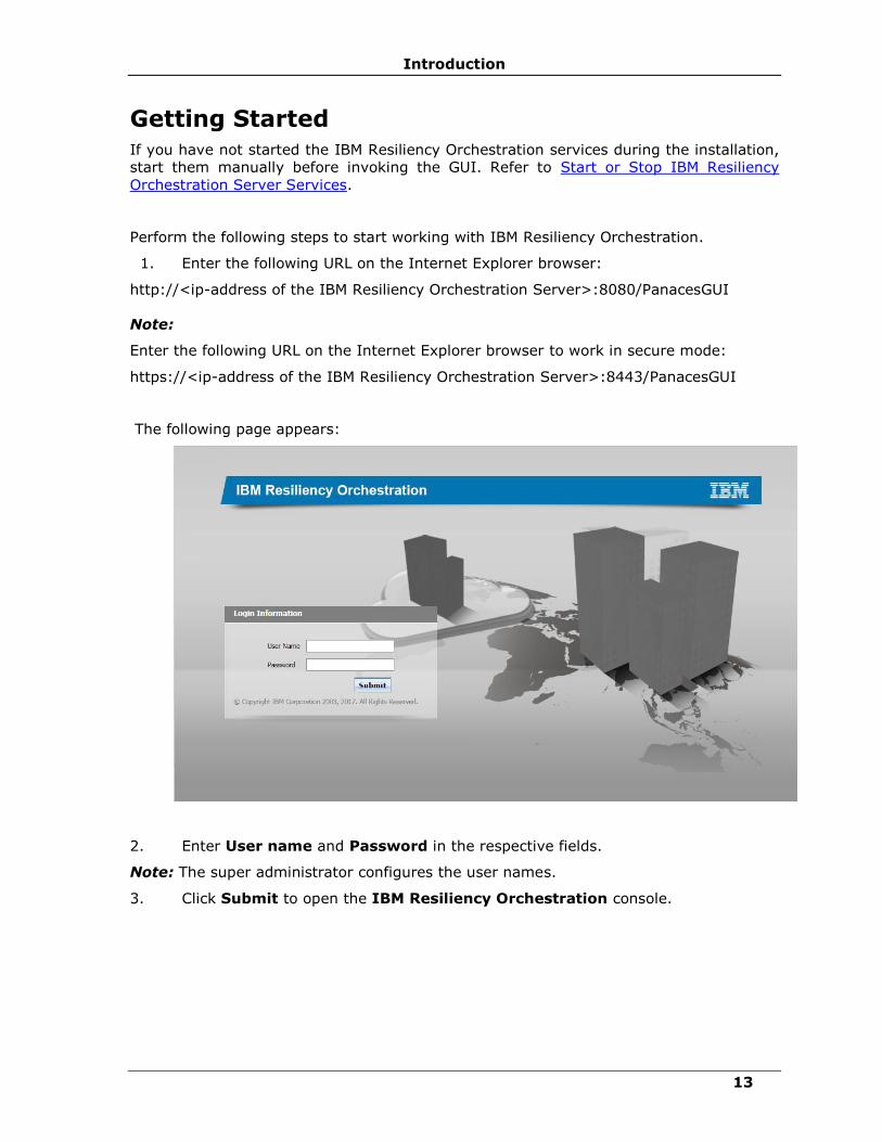
Getting Started
If you have not started the IBM Resiliency Orchestration services during the installation,
start them manually before invoking the GUI. Refer to Start or Stop IBM Resiliency
Orchestration Server Services.
Perform the following steps to start working with IBM Resiliency Orchestration.
1. Enter the following URL on the Internet Explorer browser:
http://<ip-address of the IBM Resiliency Orchestration Server>:8080/PanacesGUI
Note:
Enter the following URL on the Internet Explorer browser to work in secure mode:
https://<ip-address of the IBM Resiliency Orchestration Server>:8443/PanacesGUI
The following page appears:
2. Enter User name and Password in the respective fields.
Note: The super administrator configures the user names.
3. Click Submit to open the IBM Resiliency Orchestration console.

IBM Resiliency Orchestration Administrator’s Guide
© IBM Corporation 2017 14
Using Online Help
About Online Help
The console includes an HTML-based, cross-platform online help system. It provides
information about using IBM Resiliency Orchestration features and enables you to find
information about a specific task.
For best results, view the help in Internet Explorer version 5.0 or later and Mozilla.
Launching Online Help
You can launch the online help system by clicking Help > Help Contents.
The online help opens in your default Web browser. In the Web browser, the left pane
contains the Contents, Index, Search and Glossary tabs. Navigate to different topics
by clicking on them.
The Browser Environment
You can use the browser's navigation aids to navigate through the online help. You can
resize the browser window to the desired size.
Use the Back button of the browser to return to the previously viewed topic. Use the
Forward button to go to the topic that was displayed prior to going back.
Hiding/ Showing the Navigation Pane
If you want to hide the navigation pane in the online help system, which includes the
Contents, Index, Search, and Glossary tabs, click at the top left of the navigation
pane. If you have hidden the navigation pane and want to see it again, click the
Contents, Index, Search, or Glossary button.

Introduction
15
Navigation Bar
The Navigation Bar on the IBM Resiliency Orchestration window provides shortcut
options to navigate through the different features of the product.
The Navigation Bar provides the following tabs. Click any of these tabs to use the
relevant features of IBM Resiliency Orchestration.
• Monitor
• Manage
• Drills
• Reports
• Discover
• Admin
• Logout
NOTE:
At any point, if you want to go to Home page, click icon.
Breadcrumbs
The IBM Resiliency Orchestration windows display breadcrumbs, a type of secondary
navigation that enables users to identify their location in the application. Breadcrumbs
provide a trail of the pages visited by the users. Links to these pages help the user to
access the required page from the current location with a single click.
Breadcrumbs appear horizontally below the navigation and title bars.

IBM Resiliency Orchestration Administrator’s Guide
© IBM Corporation 2017 16
Working Area
This is the key functional area of the IBM Resiliency Orchestration window. This area
displays windows for different features depending on the tabs chosen on the navigation
bar. You can also view the current execution windows and perform different BCO
operations.
Right Pane
This pane displays the list of configured Groups along with a drop-down menu from
which you can select the criteria for displaying the Group information.
This information is displayed on the Right pane for any tab chosen on the navigation bar.
Additionally, you can perform certain configuration operations by clicking the link or by
selecting different options displayed in the pane. For example, on the Notifications
window, click Add Notification List in the right pane to set up a new notification list to
receive Event notifications.
Administration Overview
IBM Resiliency Orchestration Administration console allows you to perform various
administration activities like creating, modifying or deleting the users, configuring
notification lists, agents, and backup manager, managing logs and handling IBM Cloud
Continuity™ server failover.
Navigate to the IBM Resiliency Orchestration Administration console by clicking the
Admin link on the navigation bar.
It displays the following links.
Go to Users
Go to Notifications
GO to Agents
Go to Logs
Go to Backup
Go to Server Failover
Go to Directory Server Details (Applicable only for Advanced User Role Management)
Go to System Events
Go to License
Go to Operational History

Introduction
17
About IBM Resiliency Orchestration
You can view the product license information by clicking Help > About on the navigation
bar. This window displays the following information about IBM Resiliency Orchestration:
▪ Current Version details
▪ IBM Resiliency Orchestration Environments
▪ Server Details
▪ Acknowledgements
▪ Version History
Alternatively, you can view the version of IBM Resiliency Orchestration by entering the
following command at $EAMSROOT/bin location in the IBM Resiliency Orchestration
server
▪ ./panaces version
Log Out
Logs out the current user from IBM Resiliency Orchestration. You are then taken to the
IBM Resiliency Orchestration Login page to log on to the product again.
Help
Select Help to navigate through the following options in the secondary navigation bar.
▪ Contents & Index - Provides quick accessibility to the online information about
the product.
▪ About IBM Resiliency Orchestration - Displays the following information on
IBM Resiliency Orchestration:
▪ Product information
▪ Version details
▪ Copyright information
NOTE:
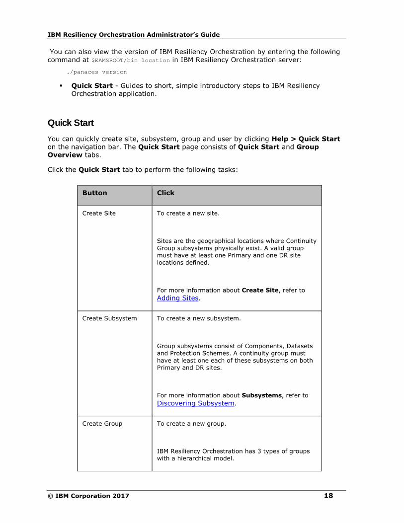
IBM Resiliency Orchestration Administrator’s Guide
© IBM Corporation 2017 18
You can also view the version of IBM Resiliency Orchestration by entering the following
command at $EAMSROOT/bin location in IBM Resiliency Orchestration server:
./panaces version
▪ Quick Start - Guides to short, simple introductory steps to IBM Resiliency
Orchestration application.
Quick Start
You can quickly create site, subsystem, group and user by clicking Help > Quick Start
on the navigation bar. The Quick Start page consists of Quick Start and Group
Overview tabs.
Click the Quick Start tab to perform the following tasks:
Button Click
Create Site To create a new site.
Sites are the geographical locations where Continuity Group subsystems physically exist. A valid group must have at least one Primary and one DR site locations defined.
For more information about Create Site, refer to
Adding Sites.
Create Subsystem To create a new subsystem.
Group subsystems consist of Components, Datasets and Protection Schemes. A continuity group must have at least one each of these subsystems on both Primary and DR sites.
For more information about Subsystems, refer to
Discovering Subsystem.
Create Group To create a new group.
IBM Resiliency Orchestration has 3 types of groups with a hierarchical model.

Introduction
19
Button Click
▪ An AG comprises of many RGs.
▪ 3 Site Group essentially comprises of 3 AGs [Primary, Secondary and Remote] and these AGs contain RGs.
For more information about Groups, refer to
Creating / Editing Groups.
Changing Password
The Resiliency Orchestration administrator creates the login credentials of the user, the
user needs to login to the Resiliency Orchestration system to change the password. If
the user has logged in for the first time, changing password is mandatory. The following
figure displays the Resiliency Orchestration Change Password screen, which prompts the
user to change the password.
Note
The Resiliency Orchestration administrator creates the first login credentials for a user.
Reset Password
The Super Administrator only can reset the password of a user. The Super Administrator
can initiate the change password option through the admin screen. Then the user
receives an email to the email id configured in the profile, as shown in the following
figure:

IBM Resiliency Orchestration Administrator’s Guide
© IBM Corporation 2017 20
The user needs to click the password reset link to reset the password. The Super
Administrator needs to use this procedure to unblock the user.

Introduction
21
Architecture Overview
Overview
IBM Resiliency Orchestration is the industry leading application, continuity management
software for open system applications and databases. It is a framework based continuity
management software that enables consistent operational interfaces, and reduces the
expertise required to configure and operate the application continuity and disaster
recovery solutions.
IBM Resiliency Orchestration encapsulates all the required intelligence – processes and
procedures required to interface with application, replication mechanism, servers,
storage, and networks to automate deployment and operation of the continuity solution.
IBM Resiliency Orchestration offers a single console view of enterprise IT continuity
health. It interfaces with the various layers of the continuity solutions and reports
deviation on Recovery Point Objective (RPO) and Recovery Time Objective (RTO) of the
application, in real time.
With its application aware framework, IBM Resiliency Orchestration significantly reduces
the operational costs associated with the management of continuity assets, increases
the productivity of the operations staff and provides continuity assurance for mission
critical applications.
IBM Resiliency Orchestration provides coherent and consistent binding of the state of
applications and status of data at the time of an outage, so that recovery is quick,
reliable and needs little or no expertise.
IBM Resiliency Orchestration Administrator’s Guide
© IBM Corporation 2017 22
Key Features
Key features of IBM Resiliency Orchestration include:
1. Disaster recovery management for multi-site DR environments with the following
capabilities:
• Continuity Monitoring
▪ Provides a dashboard view of the real time status of disaster recovery
environment including the health of the sites, applications, replication
mechanisms and readiness of the disaster recovery systems for recovery.
▪ Provides visual representation of the entire disaster recovery environment.
▪ Application aware Event Manager provides support for multiple severity
events.
▪ Supports multiple notification mechanisms, including EMS, emails and text
messages.
▪ Computes and tracks current recovery point for each application and reports
deviations against set RPO.
▪ Detects application environment and configuration changes and provides
alerts on impact.
▪ Provides real time reports on data lag between primary and DR systems.
▪ Provides events dashboard across all applications.
▪ Correlates various infrastructure failures and events and provides support for
root cause analysis.
▪ Monitors and provides real time information on WAN link utilization and
health.
▪ Estimates the recovery time for the various components of the solution –
server, application, data recovery, data consistency. Provides breakup of
recovery steps, and estimated recovery time for each of these steps.
▪ Performs real time monitoring of replication infrastructure and provides
replication details including replicated data sizes, failure and success events
and vendor specific replication object details.
▪ Provides database specific transaction information on primary and remote
systems.
▪ Provides uniform replication monitoring interface to all replicators.
▪ Continuity Management
▪ Provides best practice template based application provisioning into the
Continuity infrastructure.
Introduction
23
▪ Provides extensive customization capability of the templates using a visual
workflow editor.
▪ Provides automated failover and fallback management, integrating into
industry standard databases and applications.
▪ Provides automated switchover and switchback management.
▪ Provides interfaces to start and stop continuity and replication operations for
maintenance purpose.
▪ Provides RPO management to maintain the current data loss within the
continuity objectives. Replication can be prioritized for applications managed
by IBM Resiliency Orchestration.
▪ Provides unified replication management, integrating into third party
replication products.
▪ Provides template based policies and automated execution of policies for
Events.
▪ Provides control to perform operations at an individual application level as
well as group of applications.
▪ Test Exercise Management
▪ Provides intrusive and non-intrusive testing capability and test DR readiness
without impacting production services.
▪ Allows test suite customization to meet specific environments.
▪ Provides pre-packaged template based test exercises.
▪ Restores the replication state after performing testing.
▪ Displays real time status of the test execution.
▪ Facilitates testing on snapshot copy apart from the target copy on the DR
site.
▪ Displays “pre-test” checks to improve test success.
▪ Provides option to start, stop, abort, roll back and continue test.
▪ Provides per application test dashboard.
▪ Continuity Reports
▪ Graphical and tabular reports on various continuity management and
monitoring areas including RPO, RTO, Continuity operations, data replication
and WAN utilization.
▪ Provide daily, weekly, monthly, quarterly and yearly reports per the
configurable options.
▪ Provides comprehensive filters based on RPO, RTO (list of filters to provide).
IBM Resiliency Orchestration Administrator’s Guide
© IBM Corporation 2017 24
▪ Discovery
▪ Provides a complete inventory of DR infrastructure including servers,
replication software, database, network and applications.
▪ Provides auto discovery for replicators.
▪ Provides relationship and detailed configuration of discovered Subsystems and
binds them as groups.
▪ Provides pre-packaged templates to assist in modeling the DR infrastructure.
2. Support for Heterogeneous technologies:
▪ Support for Clusters
Clustering is the common term for distributing a service over a number of servers in
order to increase fault tolerance and to support loads larger than a single server is able
to handle. It is often used for large scale and mission critical applications where there
can be no downtime. A cluster contains servers which share state at some level.
IBM Resiliency Orchestration supports Hardware Clustering and Software Clustering:
▪ High availability cluster (also called Failover clusters, Hardware Clustering,
etc) are used to make sure no loss of service occurs when the primary server
fails. Usually, in this case, secondary hardware is present to take over.
▪ Software Clustering (also called Application Clusters) is a method of turning
multiple computer servers into a cluster (a group of servers that acts like a
single system). Clustering software is installed in each of the servers in the
group. Each of the servers maintains the same information and collectively
they perform administrative tasks such as load balancing, determining node
failures, and assigning Failover task.
Hence, IBM Resiliency Orchestration supports application clusters by monitoring the
application cluster nodes, and ensuring when the entire cluster is not available to enable
remote disaster recovery site take over.
▪ Support for Software and Hardware Data Protection Technologies
In real-time data protection, the data is protected on a real time basis wherein the data
from the host server is copied onto the remote location as soon as the data is changed,
over the network. IBM Resiliency Orchestration supports the following types of
protection technologies:
▪ Storage-based replication
Storage-based replication does not operate on the host computer. This kind of
replication occurs at the storage device level. The disk arrays manage the replication of
data between sites, relieving the hosts of the replication process.
▪ Switch-based replication
The replication is at the storage network level. The switch replicates the data from one
site to a switch that receives the data at another site.
▪ Host-based replication

Introduction
25
Host-based replication typically resides at the file system or logical volume level within
the operating system. Like storage-based offerings, it's usually transparent to the
application, but certainly not transparent to the host operating system or hardware.
Advantages of this method of replication include, ability to replicate to heterogeneous
storage and similar (not necessarily identical) systems and ability to reduce required
bandwidth.
▪ File based Replication Technologies
▪ Host based file replicator products
The modified data at the primary site is identified based on the file modification time
stamps and shipped over the network using the file replicator. This method combines
the best of the benefits of remote mirroring technologies and software protection
technologies.
▪ Database Replication Technology
Data replication is at the logical level by re-constructing the database transactions at the
remote server. This method has the advantage of minimizing the bandwidth required. It
also supports protection against rolling disasters and user errors.
▪ Support for Databases and Cluster Applications
▪ IBM Resiliency Orchestration monitors all the servers and applications assets
across the sites and ensures workflow co-ordination among them.
▪ IBM Resiliency Orchestration performs database setup on the near site with
an initial copy of the database from the production to deploy new applications
into DR.
▪ Support for Infrastructure
▪ IBM Resiliency Orchestration is configured into various devices like servers,
storage, network, and WAN to monitor the continuity health of the devices.

IBM Resiliency Orchestration Administrator’s Guide
© IBM Corporation 2017 26
Key Benefits
IBM Resiliency Orchestration enables organization to effectively manage the continuity
solutions and provide continuity assurance to the business with the following
advantages:
▪ Accurate state information on the health of continuity systems, help IT managers
resolve problems quickly.
▪ Automated monitoring significantly reduces the load on the operations staff and
increases their productivity.
▪ Automated continuity management assures application continuity and makes
recovery reliable and uniform across the enterprise.
▪ Deep application integration reduces the load on various IT administrator/
operations staff and increases their productivity.
▪ Provisioning of new applications into continuity assets is very fast and non-
intrusive to production.
▪ Disaster readiness verification becomes practical and achievable with test
automation.
▪ Cost avoidance in DR drills, as more tests can be performed within the same
period with less vendor support.
▪ Increased uptime for the production applications, as production systems are not
impacted during testing.
▪ CIOs get consolidated business view of all the systems covered under Continuity.
▪ Detailed historical reports enable department and business unit heads identify
deviations with internal processes and enable corrective measures.
▪ SLA management becomes easy with real-time information availability on various
elements of the continuity infrastructure.
▪ By automating several monitoring functions, IBM Resiliency Orchestration
increases the productivity of the skilled administrative staff.
▪ Assists in identifying problems through event correlation and helps fix the DR
systems timely.
▪ Automated template based solutions makes provisioning of new applications into
DR, quick and non-intrusive to IT operations.
▪ Automated continuity operations and RPO management assures continuity and
makes the recovery uniform across the enterprise.
▪ Pre-defined and automated execution of policies ensures uniform event response
across the enterprise, irrespective of the time of day and non-availability of
people and expertise.

Introduction
27
▪ Automated testing ensures zero errors.
▪ No production downtime - Test DR site readiness without impacting production
services.
▪ Comprehensive reports provide a high level test status, execution details and
differences with past testing result.

IBM Resiliency Orchestration Administrator’s Guide
© IBM Corporation 2017 28
How IBM Resiliency Orchestration Works?
IBM Resiliency Orchestration architecture is a distributed approach that ties together
business goals, DR workflow and solution infrastructure management to deliver an
enterprise class continuity manager product.
The Business Layer provides a way to specify business goals and monitor and manage
how well they are met. Specifically, the Business Layer:
▪ Translates application continuity goals to RPO metrics.
▪ Translates time of day based responses to coordinated action for each part of the
solution.
The Process Layer provides proven, industry tailored templates for automating DR
workflow involved in deploying and supporting IT continuity solution. Specifically, the
Process Layer:
▪ Standardize interactions and automates sequences of steps required for data
consistency and application continuity.
▪ Provides Policy engine to program and automate time of day based responses to
events.
▪ Automates tasks such as scheduled testing, report generation and configuration
change discovery.
The Operations Layer interfaces with the various components in the solution to
monitor and manage to meet the overall business continuity goals. Specifically, the
Operations Layer:
▪ Supports a distributed framework for component management.
▪ Supports an event bus and interfaces with other management packages.
IBM Resiliency Orchestration offers a single web based console and wizard based setup
and configuration. It inter-operates with leading vendor applications, replication
products and server, storage and network environment.
Introduction
29
Understanding Concepts
Discovery
Discovery Overview
Discovery provides information on Sites, Subsystems, and Groups associated with the
DR environment. Discovery allows you to configure Subsystems into the DR
infrastructure. This has to be performed immediately after creating sites.
The IBM Resiliency Orchestration supports the following Discovery types:
▪ Manual Discovery – You can manually discover Components, Datasets, and
Protection Schemes in a DR environment.
▪ Auto Discovery - IBM Resiliency Orchestration automatically discovers the
Components, Datasets, and Protection Schemes in a DR environment.
Note:
User with Super Administrator and Administrator privileges can discover Components,
Datasets, and Protection Schemes.
You can configure Sites, Subsystems and Groups by clicking the Discovery tab on the
navigation bar.
The Discovery tab provides the following links:
▪ Sites
▪ Subsystems
▪ Groups

IBM Resiliency Orchestration Administrator’s Guide
© IBM Corporation 2017 30
Sites Overview
A Site defines a location. It can be a PR site or a DR site or a Remote site. A site is the
location of Components, Datasets, and Protection Schemes in a DR environment.
IBM Resiliency Orchestration supports Disaster recovery management for two and three
sites DR environments.
The diagrammatic representation of two sites DR environment is as shown below:
The Sites area on the Home page window provides quick information on number of
configured sites.
The different status of a site is as follows:
Status Description
Active The site is Active when all the Groups of the site are Active.
Inactive The status refers to the non-working condition of site. The site is Inactive when none of the Groups belonging to the
site are Active.
Degraded A site is Degraded if there are few Groups that are Active and few other Groups that are Inactive or Degraded in this site.
N/A (Not Applicable)
Site status becomes Not Applicable when no Groups are available for the site.
Note:
When the group is in Maintenance mode, the site status might not get updated as site
status is computed based on the Group status.
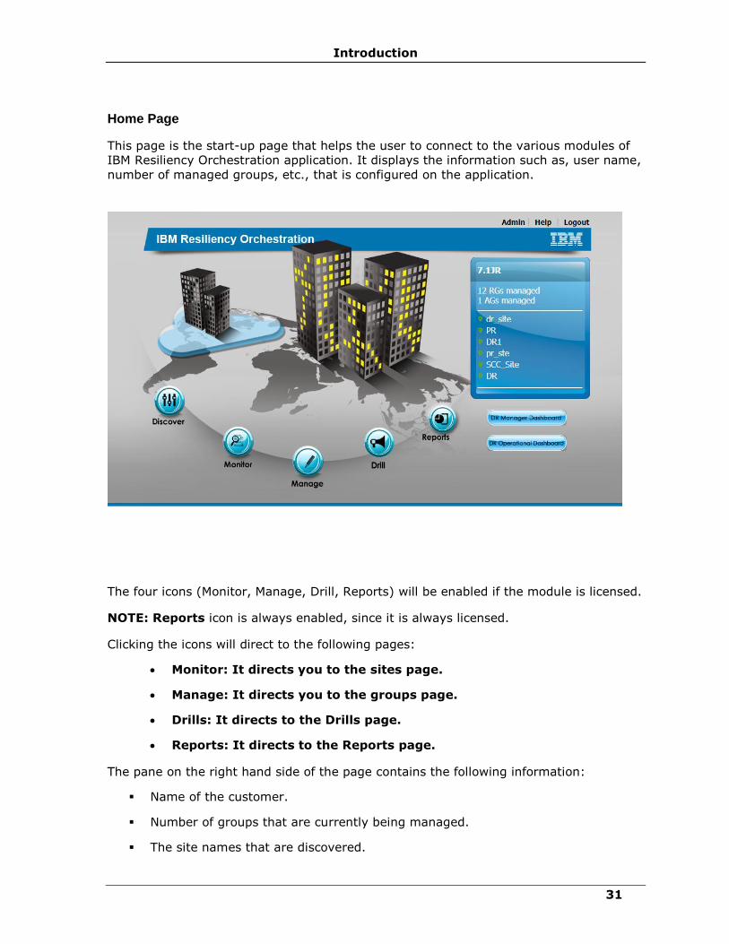
Introduction
31
Home Page
This page is the start-up page that helps the user to connect to the various modules of
IBM Resiliency Orchestration application. It displays the information such as, user name,
number of managed groups, etc., that is configured on the application.
The four icons (Monitor, Manage, Drill, Reports) will be enabled if the module is licensed.
NOTE: Reports icon is always enabled, since it is always licensed.
Clicking the icons will direct to the following pages:
• Monitor: It directs you to the sites page.
• Manage: It directs you to the groups page.
• Drills: It directs to the Drills page.
• Reports: It directs to the Reports page.
The pane on the right hand side of the page contains the following information:
▪ Name of the customer.
▪ Number of groups that are currently being managed.
▪ The site names that are discovered.

IBM Resiliency Orchestration Administrator’s Guide
© IBM Corporation 2017 32
▪ DR Manager Dashboard: It directs to the DR Manager Dashboard page.
▪ DR Operational Dashboard: It directs to the DR Operational Dashboard page.
The links on the top will direct to the following pages:
▪ Admin: It directs to the Agents page.
▪ Discover: It directs to the Groups page.
▪ Help: It pops-up the online help file of IBM Resiliency Orchestration.
▪ Logout: This logs out the user.
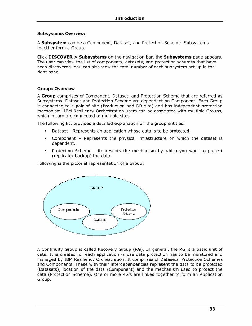
Introduction
33
Subsystems Overview
A Subsystem can be a Component, Dataset, and Protection Scheme. Subsystems
together form a Group.
Click DISCOVER > Subsystems on the navigation bar, the Subsystems page appears.
The user can view the list of components, datasets, and protection schemes that have
been discovered. You can also view the total number of each subsystem set up in the
right pane.
Groups Overview
A Group comprises of Component, Dataset, and Protection Scheme that are referred as
Subsystems. Dataset and Protection Scheme are dependent on Component. Each Group
is connected to a pair of site (Production and DR site) and has independent protection
mechanism. IBM Resiliency Orchestration users can be associated with multiple Groups,
which in turn are connected to multiple sites.
The following list provides a detailed explanation on the group entities:
▪ Dataset - Represents an application whose data is to be protected.
▪ Component – Represents the physical infrastructure on which the dataset is
dependent.
▪ Protection Scheme - Represents the mechanism by which you want to protect
(replicate/ backup) the data.
Following is the pictorial representation of a Group:
A Continuity Group is called Recovery Group (RG). In general, the RG is a basic unit of
data. It is created for each application whose data protection has to be monitored and
managed by IBM Resiliency Orchestration. It comprises of Datasets, Protection Schemes
and Components. These with their interdependencies represent the data to be protected
(Datasets), location of the data (Component) and the mechanism used to protect the
data (Protection Scheme). One or more RG's are linked together to form an Application
Group.
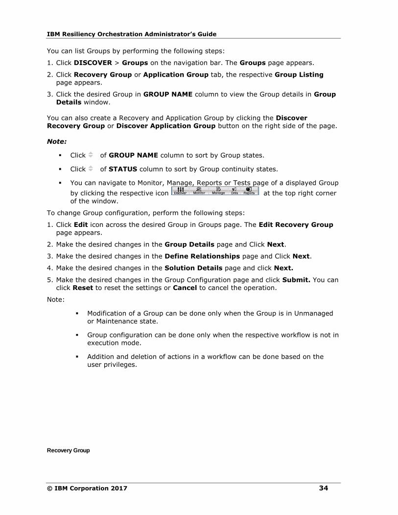
IBM Resiliency Orchestration Administrator’s Guide
© IBM Corporation 2017 34
You can list Groups by performing the following steps:
1. Click DISCOVER > Groups on the navigation bar. The Groups page appears.
2. Click Recovery Group or Application Group tab, the respective Group Listing
page appears.
3. Click the desired Group in GROUP NAME column to view the Group details in Group
Details window.
You can also create a Recovery and Application Group by clicking the Discover
Recovery Group or Discover Application Group button on the right side of the page.
Note:
▪ Click of GROUP NAME column to sort by Group states.
▪ Click of STATUS column to sort by Group continuity states.
▪ You can navigate to Monitor, Manage, Reports or Tests page of a displayed Group
by clicking the respective icon at the top right corner
of the window.
To change Group configuration, perform the following steps:
1. Click Edit icon across the desired Group in Groups page. The Edit Recovery Group
page appears.
2. Make the desired changes in the Group Details page and Click Next.
3. Make the desired changes in the Define Relationships page and Click Next.
4. Make the desired changes in the Solution Details page and click Next.
5. Make the desired changes in the Group Configuration page and click Submit. You can
click Reset to reset the settings or Cancel to cancel the operation.
Note:
▪ Modification of a Group can be done only when the Group is in Unmanaged
or Maintenance state.
▪ Group configuration can be done only when the respective workflow is not in
execution mode.
▪ Addition and deletion of actions in a workflow can be done based on the
user privileges.
Recovery Group

Introduction
35
A Recovery Group (RG) is a basic unit of data with associated protection and
infrastructure mappings that needs to be protected and managed by IBM Resiliency
Orchestration.
One or more RG's are associated together to form an Application Group (AG).
Application Group
An Application Group (AG) contains a set of RGs. A RG cannot be part of more than one
AG at a time. AGs can be considered as container of RGs.
RGs belonging to different solution signatures can be added into an AG. Any operation
which can be executed on an RG (if it is independent) can be executed even if it is a part
of an AG.
Example: A banking application requires three Oracle databases and one file system
directory on the Application server. There are four RG's created, one for each database
and another for the file system data. All these four RG's form a single AG.

IBM Resiliency Orchestration Administrator’s Guide
© IBM Corporation 2017 36
Status of a Group
Status of a Group
A Group (RG or AG) can undergo state change during its life cycle. The status of the
Group is shown along with its name in the Groups window of the DISCOVERY page.
The status value of a Group provides information such as:
▪ If any critical, serious or warning events are raised in the group.
▪ If the Group is being in Managed or Maintenance mode.
The Group status information is divided into two parts:
Execution Mode
Group Status
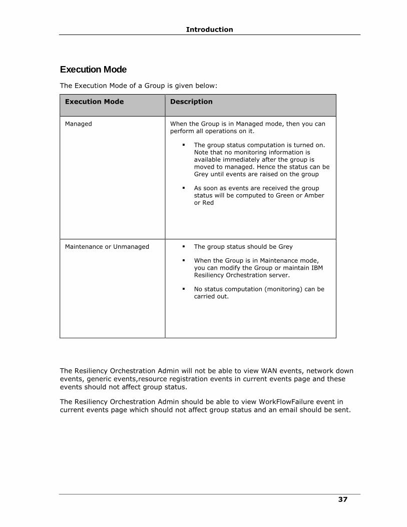
Introduction
37
Execution Mode
The Execution Mode of a Group is given below:
Execution Mode Description
Managed When the Group is in Managed mode, then you can perform all operations on it.
▪ The group status computation is turned on. Note that no monitoring information is available immediately after the group is
moved to managed. Hence the status can be Grey until events are raised on the group
▪ As soon as events are received the group status will be computed to Green or Amber or Red
Maintenance or Unmanaged ▪ The group status should be Grey
▪ When the Group is in Maintenance mode, you can modify the Group or maintain IBM Resiliency Orchestration server.
▪ No status computation (monitoring) can be carried out.
The Resiliency Orchestration Admin will not be able to view WAN events, network down
events, generic events,resource registration events in current events page and these
events should not affect group status.
The Resiliency Orchestration Admin should be able to view WorkFlowFailure event in
current events page which should not affect group status and an email should be sent.

IBM Resiliency Orchestration Administrator’s Guide
© IBM Corporation 2017 38
Execution Status
Execution state of a Group reflects health of the production data availability and also,
the status of all the dependent infrastructure components, protection and database
objects. This state information is valid only when the Group is in MANAGED mode.
This state information is ignored in other execution modes.
Following Execution State values are possible in MANAGED mode:
Execution Status Description
The production and DR data is available for the Group and all the dependent objects
are running.
Group status is green when there are no critical, serious and
warning events open and only info events are present.
Production or DR data is unavailable currently.
This may be due to the PR or DR server down condition. This state may also mean that
one or multiple (including all) dependent objects are down
currently.
Group status is changed to Red if there are any alertable critical events raised.
Production or DR data maybe in the database down condition.
However, one or multiple dependent objects of the Group are down either at the PR site or the DR site.
Group Status is changed to Amber if any alertable warning and serious events are raised.
Group Status is changed to Grey when no monitoring information is available.
When no monitoring information available( there are no
alertable events avialble).
When Monitoring license is not enabled for the group Eg: group status not applicable for Test only license.

Introduction
39
Group Health Status of a Group is computed automatically, whenever a change in the
state of any of the dependent objects is detected. During BCO execution, the Group will
have following change status for the described conditions:
Group Health Status
change during BCO
Description
Green to Amber This transition occurs, if any action associated with the Group fails or is awaiting input from you.
If the Group is already in Amber or Red state, the status will
not change.
Amber to Green If you have provided the required input and resumed the BCO
execution. If there are no further failures, the Group execution status will be changed from Amber to Green.
Amber to Green If you have aborted the action requiring the input, it will be taken as an input and the execution status will be changed to Active. However, the continuity status of the Group will
change to DR Impaired, as you have aborted the action.
For the above conditions, the change in RGs execution status will be immediate.
However,similar changes for AGs will take up to one minute.
Note:
Await for events to compute status when the group is in the maintenance mode.
After Switchover or Swichback, it takes time to display the group status.
Recovery Status
Recovery status reflects the current state of the Group with respect to either crash
recovery or backup/ recovery from IBM Resiliency Orchestration software metadata
(Internal Database).
Valid Recovery State values are:
Recovery status Description
NEED RECOVERY A Group will be put into this Recovery State, when the IBM Resiliency Orchestration server is started with a recovery option. In this state, no continuity operations are allowed to be executed. Events will
not be reported.
RECOVERING A Group, whose state information is being recovered by the Recovery Wizard, is put into this state. During
this state also, no new operations may be executed
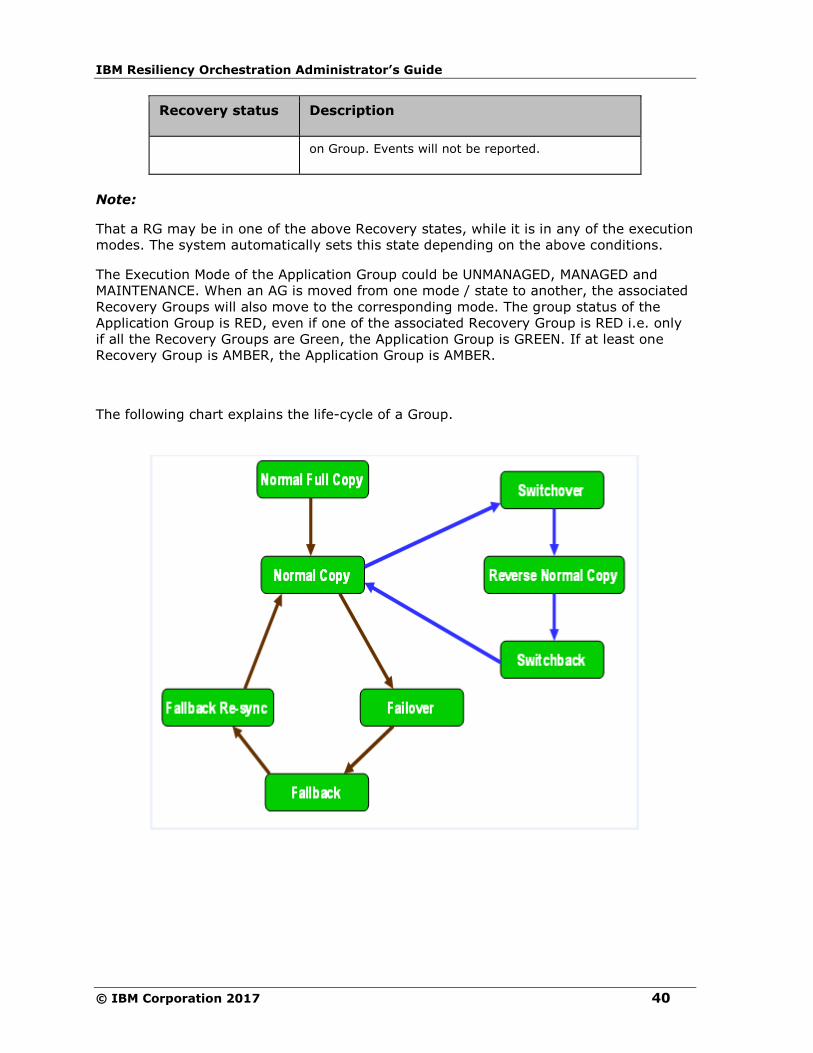
IBM Resiliency Orchestration Administrator’s Guide
© IBM Corporation 2017 40
Recovery status Description
on Group. Events will not be reported.
Note:
That a RG may be in one of the above Recovery states, while it is in any of the execution
modes. The system automatically sets this state depending on the above conditions.
The Execution Mode of the Application Group could be UNMANAGED, MANAGED and
MAINTENANCE. When an AG is moved from one mode / state to another, the associated
Recovery Groups will also move to the corresponding mode. The group status of the
Application Group is RED, even if one of the associated Recovery Group is RED i.e. only
if all the Recovery Groups are Green, the Application Group is GREEN. If at least one
Recovery Group is AMBER, the Application Group is AMBER.
The following chart explains the life-cycle of a Group.

Introduction
41
Continuity Operations on a Group
Points to remember while working with Continuity Operations:
1. If any BCO fails on a FG associated to an AG, then the BCO is considered to be failed
at AG level.
2. For a BCO on an AG to be successful, the same should be successful on all the FG's
associated to the AG.
3. Failover of an entire AG occurs when Failover on RG is triggered either manually or
because of any events.
4. Before Failover of AG, all the operations that are currently being performed on all
dependent RG's are stopped.
5. For RG's that are independent, Failover occurs at the respective RG level only.
6. Failover can happen at AG level and not at RG level. All the RG's are required to be
active for an AG to be active. There is an ordered dependency of RG's under an AG.
So, if a Failover or Fallback at AG should happen it happens on all RG's under it in
the order that is defined.
7. Every Group (AG and RG) has to be managed in the DR environment.
Note:
In all the list pages, the row is highlighted incase the group is in failover mode.
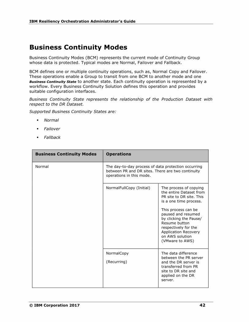
IBM Resiliency Orchestration Administrator’s Guide
© IBM Corporation 2017 42
Business Continuity Modes
Business Continuity Modes (BCM) represents the current mode of Continuity Group
whose data is protected. Typical modes are Normal, Failover and Fallback.
BCM defines one or multiple continuity operations, such as, Normal Copy and Failover.
These operations enable a Group to transit from one BCM to another mode and one
Business Continuity State to another state. Each continuity operation is represented by a
workflow. Every Business Continuity Solution defines this operation and provides
suitable configuration interfaces.
Business Continuity State represents the relationship of the Production Dataset with
respect to the DR Dataset.
Supported Business Continuity States are:
▪ Normal
▪ Failover
▪ Fallback
Business Continuity Modes Operations
Normal The day-to-day process of data protection occurring
between PR and DR sites. There are two continuity operations in this mode.
NormalFullCopy (Initial) The process of copying the entire Dataset from PR site to DR site. This is a one time process.
This process can be paused and resumed by clicking the Pause/ Resume button respectively for the Application Recovery
on AWS solution
(VMware to AWS)
NormalCopy
(Recurring)
The data difference between the PR server and the DR server is transferred from PR site to DR site and applied on the DR server.

Introduction
43
Business Continuity Modes Operations
Failover The process of transferring control or business continuity from Production site to DR site when the
Production site is down or inactive.
Fallback
A full dump of data is taken on the current PR server and applied on the configured PR server. The
business control is transferred from the current PR server (DR server) to the configured PR server.
In this operation the PR server is brought in to production. At the end of this operation, the PR server's data is ready for replication and the DR
server is made standby.
FallbackResync This operation brings the production server and DR server in sync. The PR and DR servers are made
ready for NormalCopy operation.
Change Continuity State This continuity operation allow you to move the BCM of a Group from the current BCM to a new BCM.
This operation is possible only when the Group is not executing any continuity operations currently.
A Group may be moved into only four target BCM's:
1. NORMAL RESET
2. NORMAL INACTIVE
3. FAILOVER ACTIVE
4. FALLBACK ACTIVE
Note:
This operation may be used only by an advanced
administrator to by-pass certain operations or recover from certain failures. Usage of this operation may significantly impact the Continuity Management of the Group, if not performed correctly.
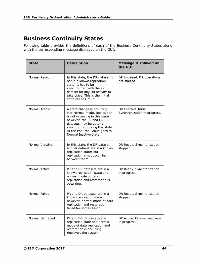
IBM Resiliency Orchestration Administrator’s Guide
© IBM Corporation 2017 44
Business Continuity States
Following table provides the definitions of each of the Business Continuity States along
with the corresponding message displayed on the GUI:
State Description Message Displayed on
the GUI
Normal Reset In this state, the DR dataset is not in a known replication
state. It has to be synchronized with the PR dataset for any DR activity to take place. This is the initial state of the Group.
DR impaired. DR operations not started.
Normal Transit A state change is occurring into Normal mode. Replication is not occurring in this state however, the PR and DR
datasets may be getting synchronized during this state. At the end, the Group goes to Normal Inactive state.
DR Enabled. Initial Synchronization in progress.
Normal Inactive In this state, the DR dataset and PR dataset are in a known replication state; but replication is not occurring between them.
DR Ready. Synchronization stopped.
Normal Active PR and DR datasets are in a known replication state and normal mode of data replication and restoration is occurring.
DR Ready. Synchronization in progress.
Normal Failed PR and DR datasets are in a known replication state however, normal mode of data
replication and restoration failed for some reason.
DR Ready. Synchronization stopped.
Normal Degraded PR and DR datasets are in replication state and normal mode of data replication and restoration is occurring. However, the system
DR Active. Failover recovery in progress.

Introduction
45
State Description Message Displayed on
the GUI
encountered intermittent errors in the normal mode of processing in the last ‘X’ minutes.
Failover Transit The PR is down and the system is transferred to DR site for production. Replication of log is suspended.
-
Failover Failed During the transit to Failover BCM, failures occurred. Functioning of PR is
down, replication is not occurring.
DR impaired.
Failover Active The control of business is switched to DR site. PR
dataset is down on PR site and replication does not occur in this site.
DR Active. Recovery complete.
Fallback Transit PR is transferred from DR site to the PR site. No replication
process is going on.
DR Ready. Fallback in progress.
Fallback Failed Transition to PR site failed. Resume Fallback again to recover. No process of replication is going on. PR is on DR site.
-
Fallback Active PR is switched to PR site. PR dataset may be up or down. But DR dataset and PR dataset are not ready for replication yet.
DR Ready. Fallback in progress.
Normal Shutdown If IBM Resiliency Orchestration software crashes or a forceful shutdown of the server is performed, Business
Continuity Operation at that time will be changed to Normal Shutdown state.
-
Normal Stopping This is a transient state operation. If Normal Copy is
-

IBM Resiliency Orchestration Administrator’s Guide
© IBM Corporation 2017 46
State Description Message Displayed on
the GUI
stopped manually (i.e, by clicking the Stop Normal Copy button), then the Group is moved in to this state until the operation is completely
stopped.
Normal Test If a test exercise is initiated on a Group, the Group is moved
in to this state. Test exercise can be initiated only when the
Group is in Normal Inactive state.
-

Introduction
47
RPO-RTO
About RPO, RTO
Recovery Point Objective
It is an acceptable amount of data loss from the last good backup prior to the point of
failure.
For example, if you consider overnight backup, the Recovery Point Objective will often
be the end of the previous day's activity.
▪ Data RPO – This is for the replication mechanism in your set-up. Data RPO of 10
minutes means data till 10 minutes ago is replicated into DR from PR.
▪ App RPO – App RPO is based on the database transaction timestamps. App RPO of
10 minutes means the last transaction applied on DR and last transaction applied
on PR is differed by 10 minutes.
Recovery Time Objective
The time taken for the business to be back online after a disaster i.e. the time taken to
get back to Business Continuity.
Example: Let us assume that the data replication is happening between PR and DR
site. A retailer determines that, in case of a system failure at the PR site, it is acceptable
to lose business data of last two hours (RPO). But after two hours the retailer cannot
afford to lose business and somehow the data must be made available to restart the
business. This is done by bringing up the DR site as PR site until the PR site is up again.
The required time taken by the retailer to start the business application at the DR site
and to move the business forward is one hour, which is known as RTO.
Managing RPO and RTO
IBM Resiliency Orchestration provides constant monitoring of Recovery Point Objective
(RPO) and Recovery Time Objective (RTO) values and provides alerts to indicate any
deviations to these goals based on the configured tolerance limits. It also provides
enough control to tune some replication parameters using which, one can alter the RPO
value, subject to the constraints of the available WAN bandwidth.
IBM Resiliency Orchestration provides the following key capabilities for RPO and RTO
management, for each database under protection:
Compute Current App RPO
Displays the desired and current RPO values and the supporting solution specific
information, such as, last log/file transaction id or name and the time when the File
System was most recently updated or modified on the PR server.
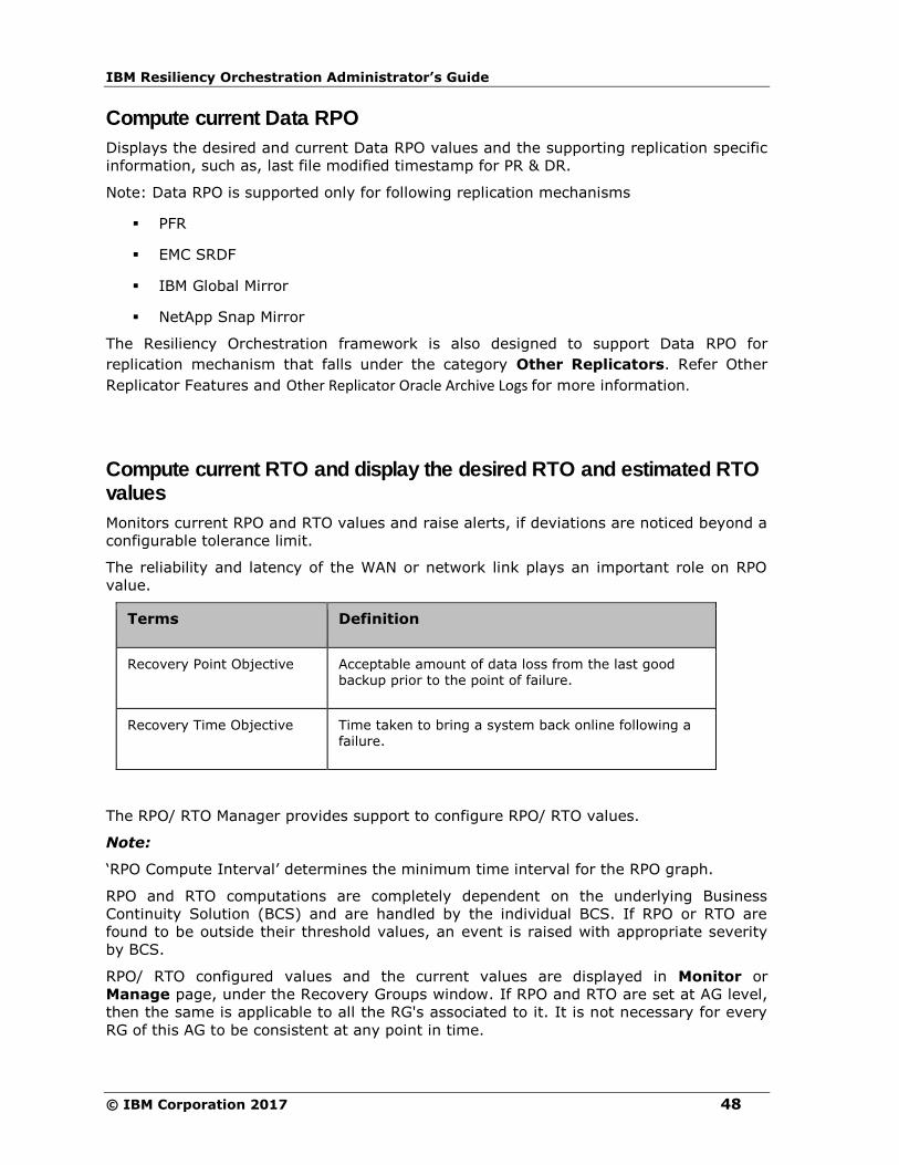
IBM Resiliency Orchestration Administrator’s Guide
© IBM Corporation 2017 48
Compute current Data RPO
Displays the desired and current Data RPO values and the supporting replication specific
information, such as, last file modified timestamp for PR & DR.
Note: Data RPO is supported only for following replication mechanisms
▪ PFR
▪ EMC SRDF
▪ IBM Global Mirror
▪ NetApp Snap Mirror
The Resiliency Orchestration framework is also designed to support Data RPO for
replication mechanism that falls under the category Other Replicators. Refer Other
Replicator Features and Other Replicator Oracle Archive Logs for more information.
Compute current RTO and display the desired RTO and estimated RTO values
Monitors current RPO and RTO values and raise alerts, if deviations are noticed beyond a
configurable tolerance limit.
The reliability and latency of the WAN or network link plays an important role on RPO
value.
Terms Definition
Recovery Point Objective Acceptable amount of data loss from the last good backup prior to the point of failure.
Recovery Time Objective Time taken to bring a system back online following a failure.
The RPO/ RTO Manager provides support to configure RPO/ RTO values.
Note:
‘RPO Compute Interval’ determines the minimum time interval for the RPO graph.
RPO and RTO computations are completely dependent on the underlying Business
Continuity Solution (BCS) and are handled by the individual BCS. If RPO or RTO are
found to be outside their threshold values, an event is raised with appropriate severity
by BCS.
RPO/ RTO configured values and the current values are displayed in Monitor or
Manage page, under the Recovery Groups window. If RPO and RTO are set at AG level,
then the same is applicable to all the RG's associated to it. It is not necessary for every
RG of this AG to be consistent at any point in time.

Introduction
49
This window lists RPO/ RTO details as given in the following table:
Field Description
Current App RPO Value Displays recently computed App RPO value for the RG.
Current App RPO Time Displays recently computed App RPO time stamp.
For example: The current App RPO time stamp is 12p.m, Monday, 4th June 2004.
Current time is 12.30 P.M., Monday, 4th June 2004.
Therefore, App RPO time-stamp indicates
30 min time lag on the date.
Configured App RPO Value These are user specified values for accomplishing recovery within stipulated time.
Time when RPO computed It is the time when the App RPO was computed.
App RPO deviation Displays the percentage deviation between the current App RPO and the configured App RPO. When the current value exceeds the configured value, it flashes in red color.
Additional RPO details Displays the dataset and the RG specific details.
The following table explains the terms associated to RTO:
Field Description
Current RTO Value Displays the recently computed RTO value for the RG.
Current RTO Time Displays the recently computed RTO time stamp.
Configured RTO value
These are user specified values for accomplishing recovery within stipulated time.
Time when RTO computed
Displays the time when RTO was computed.
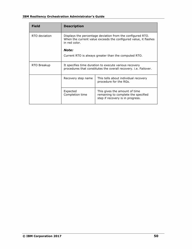
IBM Resiliency Orchestration Administrator’s Guide
© IBM Corporation 2017 50
Field Description
RTO deviation
Displays the percentage deviation from the configured RTO. When the current value exceeds the configured value, it flashes
in red color.
Note:
Current RTO is always greater than the computed RTO.
RTO Breakup It specifies time duration to execute various recovery procedures that constitutes the overall recovery. i.e. Failover.
Recovery step name This tells about individual recovery procedure for the RGs.
Expected Completion time
This gives the amount of time remaining to complete the specified
step if recovery is in progress.
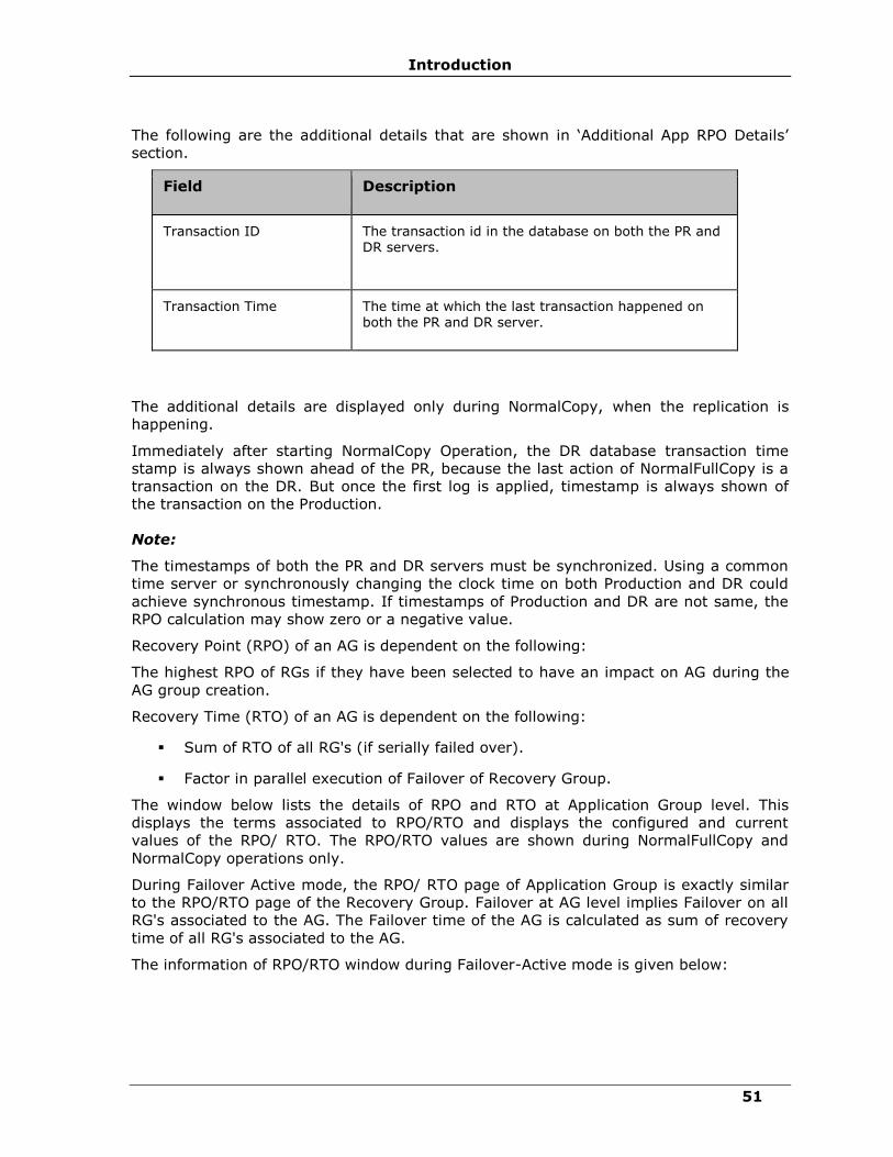
Introduction
51
The following are the additional details that are shown in ‘Additional App RPO Details’
section.
Field Description
Transaction ID
The transaction id in the database on both the PR and DR servers.
Transaction Time The time at which the last transaction happened on both the PR and DR server.
The additional details are displayed only during NormalCopy, when the replication is
happening.
Immediately after starting NormalCopy Operation, the DR database transaction time
stamp is always shown ahead of the PR, because the last action of NormalFullCopy is a
transaction on the DR. But once the first log is applied, timestamp is always shown of
the transaction on the Production.
Note:
The timestamps of both the PR and DR servers must be synchronized. Using a common
time server or synchronously changing the clock time on both Production and DR could
achieve synchronous timestamp. If timestamps of Production and DR are not same, the
RPO calculation may show zero or a negative value.
Recovery Point (RPO) of an AG is dependent on the following:
The highest RPO of RGs if they have been selected to have an impact on AG during the
AG group creation.
Recovery Time (RTO) of an AG is dependent on the following:
▪ Sum of RTO of all RG's (if serially failed over).
▪ Factor in parallel execution of Failover of Recovery Group.
The window below lists the details of RPO and RTO at Application Group level. This
displays the terms associated to RPO/RTO and displays the configured and current
values of the RPO/ RTO. The RPO/RTO values are shown during NormalFullCopy and
NormalCopy operations only.
During Failover Active mode, the RPO/ RTO page of Application Group is exactly similar
to the RPO/RTO page of the Recovery Group. Failover at AG level implies Failover on all
RG's associated to the AG. The Failover time of the AG is calculated as sum of recovery
time of all RG's associated to the AG.
The information of RPO/RTO window during Failover-Active mode is given below:

IBM Resiliency Orchestration Administrator’s Guide
© IBM Corporation 2017 52
Field Description
Current Continuity Mode Displays the mode of the continuity operation. The different modes could be NormalFullCopy, NormalCopy, Failover, Fallback and FallbackResync.
Current Continuity State Displays the current continuity state. The different continuity states are Active, Inactive and
Degraded.
Time of Failover Displays the time stamp when the Failover has complete.
The Data was recovered to Displays the time stamp when the data was recovered to the DR site.
Refer DR Solutions Supported by IBM Resiliency Orchestration for information on
solution specific RPO and RTO.
Introduction
53
Pre- requisites
▪ The network connection bandwidth must be sufficient to support replication from
primary to DR.
▪ Administrator/ root equivalent privileges are required for IBM agents.
▪ IBM requires remote console access to the servers.
▪ Disk space should be allocated on the database servers to hold transaction logs
for up to 3 business days and for full backup (equal to the size of the database
itself).
▪ There must be two sites (logical). First one termed the Production site, which
under normal operating conditions has the PR database/ application. The second
site is termed the DR site, which under normal conditions has the database/
application operating as a standby.
▪ The two sites are connected over an IP network connection. The network
connection bandwidth must be sufficient to support replication of log files from
the Production to the standby.
▪ IBM Resiliency Orchestration master server ideally resides on the DR site. There
is a IBM Resiliency Orchestration server on the Production site that is configured
as the standby IBM Resiliency Orchestration server.
▪ IBM Resiliency Orchestration master server has network access to the Production
and standby servers and all other components of the DR Solution.
Additional Support
In addition to providing documentation, IBM Technologies offers the following
services:
For assistance with IBM Resiliency Orchestration, contact technical support at
For customer support, contact our IBM help desk at
Phone: +91 80 40256811, +91 80 40256831
Toll Free: 1800 1027305
Starting and Stopping IBM Resiliency
Orchestration Server Services
To start and stop IBM Resiliency Orchestration server services manually, perform the
following steps:
1. Login to IBM Resiliency Orchestration server machine as root.
2. At the command prompt, enter one of the following commands to:
IBM Resiliency Orchestration Administrator’s Guide
© IBM Corporation 2017 54
▪ To start: $EAMSROOT/bin/panaces start
▪ To stop: $EAMSROOT/bin/panaces stop
NOTE:
When continuity operations are being executed, you should not stop IBM Resiliency
Orchestration server service.
If you are executing any BCO, perform the following steps to stop the executing BCO
before stopping the service:
1. Click Manage> Executing Workflows. The Executing workflows page is displayed.
2. Select Recovery Group filter from the drop-down list.
3. Click the Executing link in the Status column for the specific group name. The
workflow page appears.
4. Click Abort.
5. Log off from IBM Resiliency Orchestration GUI
On Server Restart
After restarting IBM Resiliency Orchestration server, continuing NormalCopy
automatically starts. If it does not start, you may need to increase the startup delay
settings for Agents.
To resume NormalCopy, open the panaces.properties file on IBM Resiliency
Orchestration server and set the below parameter to an appropriate value.
panaces.server.startupDelayForAgents
Starting and Stopping IBM Resiliency
Orchestration Agents
The scripts deployed at the time of agent installation, starts the agents when the server
is rebooted. However, the agents can be started manually without rebooting the server.
Similarly, they can be stopped using manual procedures. Moreover, the agent status can
be verified.
Starting IBM Resiliency Orchestration Agents
Starting of Agents on Windows Server
Note
Ensure that the clock setting on IBM Resiliency Orchestration server and the agent
server is in sync.
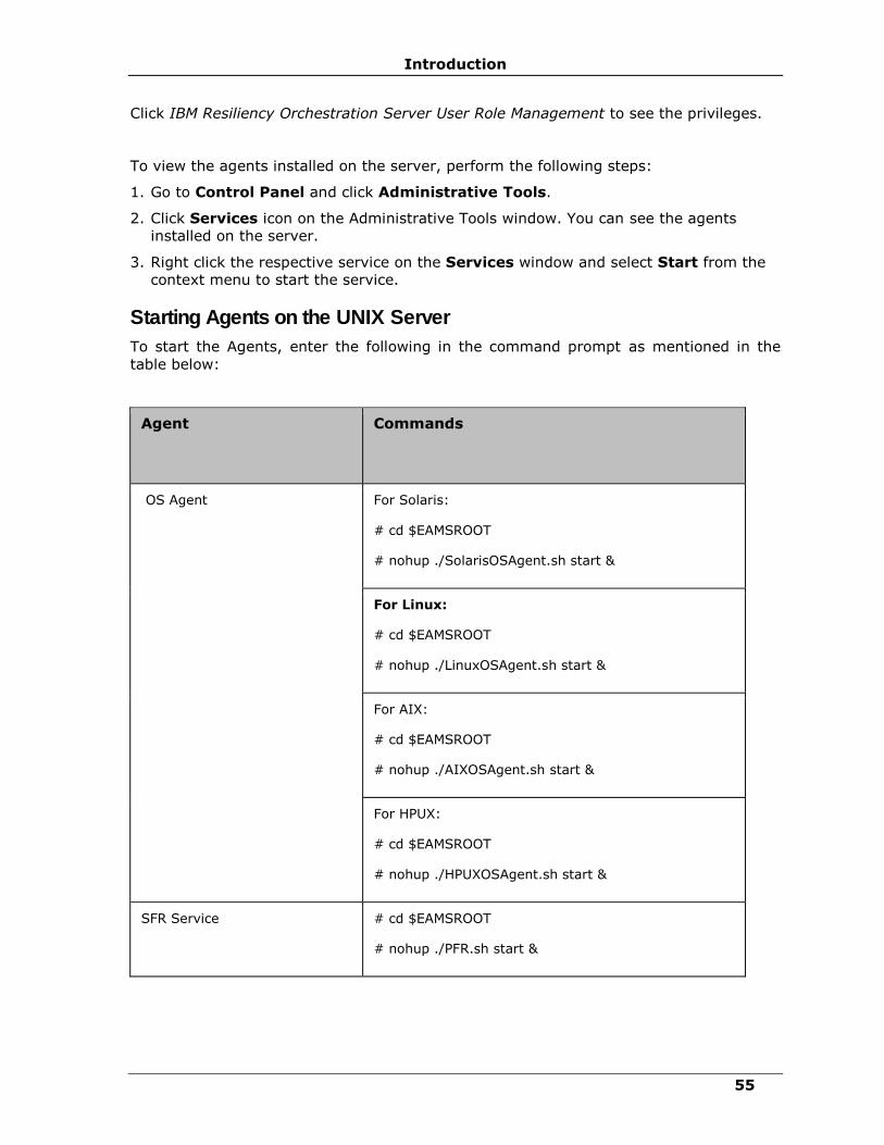
Introduction
55
Click IBM Resiliency Orchestration Server User Role Management to see the privileges.
To view the agents installed on the server, perform the following steps:
1. Go to Control Panel and click Administrative Tools.
2. Click Services icon on the Administrative Tools window. You can see the agents
installed on the server.
3. Right click the respective service on the Services window and select Start from the
context menu to start the service.
Starting Agents on the UNIX Server
To start the Agents, enter the following in the command prompt as mentioned in the
table below:
Agent
Commands
OS Agent For Solaris:
# cd $EAMSROOT
# nohup ./SolarisOSAgent.sh start &
For Linux:
# cd $EAMSROOT
# nohup ./LinuxOSAgent.sh start &
For AIX:
# cd $EAMSROOT
# nohup ./AIXOSAgent.sh start &
For HPUX:
# cd $EAMSROOT
# nohup ./HPUXOSAgent.sh start &
SFR Service # cd $EAMSROOT
# nohup ./PFR.sh start &
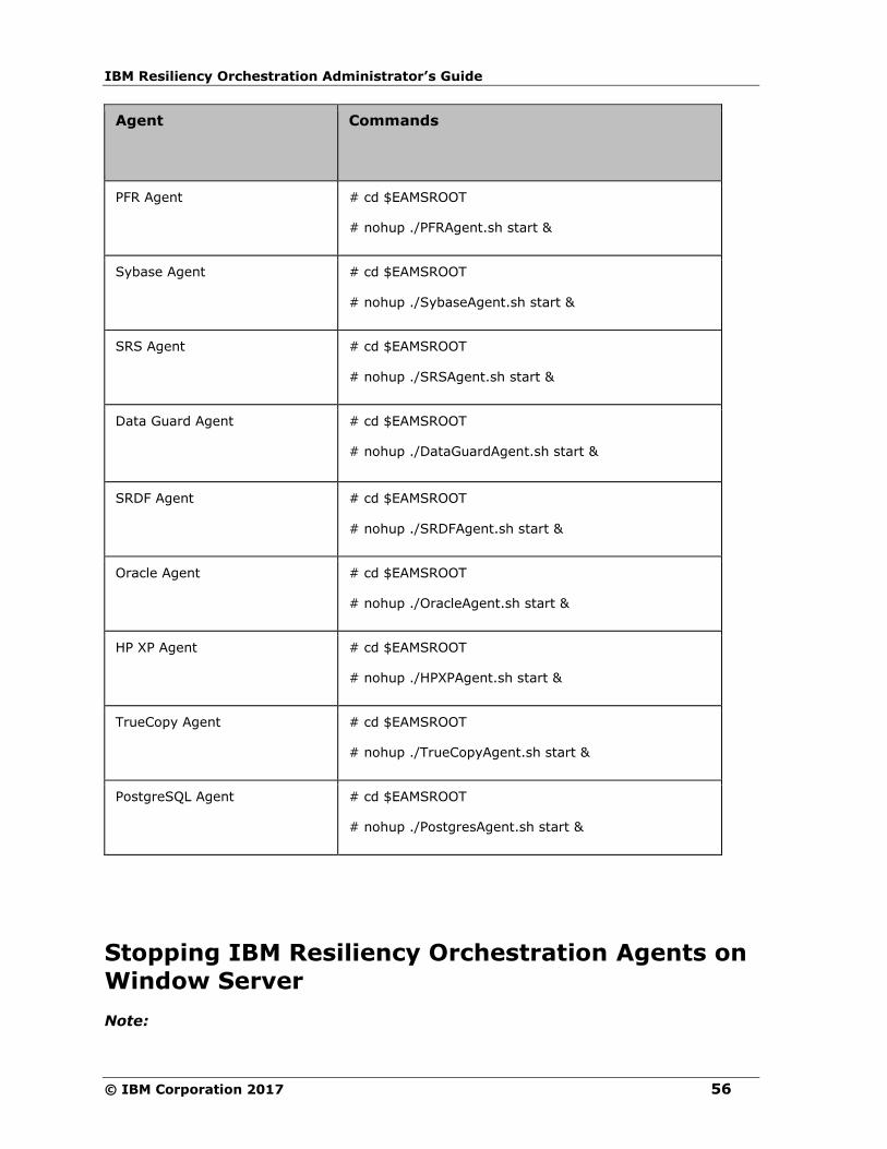
IBM Resiliency Orchestration Administrator’s Guide
© IBM Corporation 2017 56
Agent
Commands
PFR Agent
# cd $EAMSROOT
# nohup ./PFRAgent.sh start &
Sybase Agent
# cd $EAMSROOT
# nohup ./SybaseAgent.sh start &
SRS Agent # cd $EAMSROOT
# nohup ./SRSAgent.sh start &
Data Guard Agent # cd $EAMSROOT
# nohup ./DataGuardAgent.sh start &
SRDF Agent # cd $EAMSROOT
# nohup ./SRDFAgent.sh start &
Oracle Agent # cd $EAMSROOT
# nohup ./OracleAgent.sh start &
HP XP Agent # cd $EAMSROOT
# nohup ./HPXPAgent.sh start &
TrueCopy Agent # cd $EAMSROOT
# nohup ./TrueCopyAgent.sh start &
PostgreSQL Agent # cd $EAMSROOT
# nohup ./PostgresAgent.sh start &
Stopping IBM Resiliency Orchestration Agents on
Window Server
Note:

Introduction
57
Ensure that the clock setting on IBM Resiliency Orchestration server and the agent
server is in sync.
Click IBM Resiliency Orchestration Server User Role Management to see the privileges.
To view the Agents installed on the Windows server, perform the following steps:
1. Go to Control Panel > Administrative Tools.
2. Click Services icon on the Administrative Tools window. You can see the agents
installed on the server.
3. Right click the respective service on the Services window and select Stop from the
context menu to stop the service.
Stopping Agents on the UNIX Server
To stop the Agents, enter the following in the command prompt as mentioned in the
table below:
Agent
Commands
OS Agent For Solaris:
# cd $EAMSROOT
# nohup ./SolarisOSAgent.sh stop &
For Linux:
# cd $EAMSROOT
# nohup ./LinuxOSAgent.sh stop &
For AIX:
# nohup ./AIXOSAgent.sh stop &
For HPUX:
# nohup ./HPUXOSAgent.sh stop &
SFR Service # cd $EAMSROOT
# nohup ./PFR.sh stop &
PFR Agent # cd $EAMSROOT
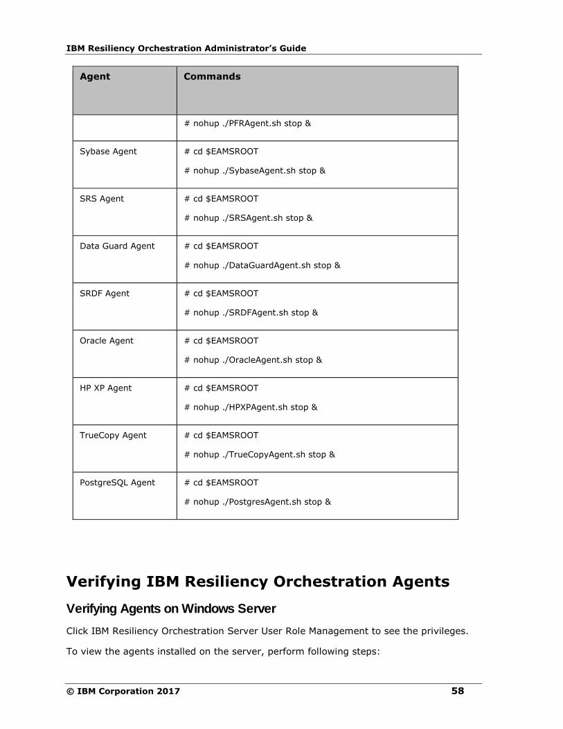
IBM Resiliency Orchestration Administrator’s Guide
© IBM Corporation 2017 58
Agent
Commands
# nohup ./PFRAgent.sh stop &
Sybase Agent
# cd $EAMSROOT
# nohup ./SybaseAgent.sh stop &
SRS Agent # cd $EAMSROOT
# nohup ./SRSAgent.sh stop &
Data Guard Agent # cd $EAMSROOT
# nohup ./DataGuardAgent.sh stop &
SRDF Agent # cd $EAMSROOT
# nohup ./SRDFAgent.sh stop &
Oracle Agent # cd $EAMSROOT
# nohup ./OracleAgent.sh stop &
HP XP Agent # cd $EAMSROOT
# nohup ./HPXPAgent.sh stop &
TrueCopy Agent # cd $EAMSROOT
# nohup ./TrueCopyAgent.sh stop &
PostgreSQL Agent # cd $EAMSROOT
# nohup ./PostgresAgent.sh stop &
Verifying IBM Resiliency Orchestration Agents
Verifying Agents on Windows Server
Click IBM Resiliency Orchestration Server User Role Management to see the privileges.
To view the agents installed on the server, perform following steps:
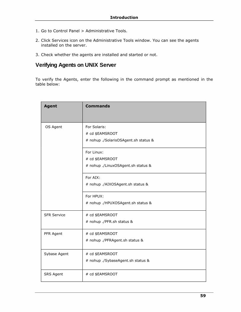
Introduction
59
1. Go to Control Panel > Administrative Tools.
2. Click Services icon on the Administrative Tools window. You can see the agents
installed on the server.
3. Check whether the agents are installed and started or not.
Verifying Agents on UNIX Server
To verify the Agents, enter the following in the command prompt as mentioned in the
table below:
Agent
Commands
OS Agent For Solaris:
# cd $EAMSROOT
# nohup ./SolarisOSAgent.sh status &
For Linux:
# cd $EAMSROOT
# nohup ./LinuxOSAgent.sh status &
For AIX:
# nohup ./AIXOSAgent.sh status &
For HPUX:
# nohup ./HPUXOSAgent.sh status &
SFR Service # cd $EAMSROOT
# nohup ./PFR.sh status &
PFR Agent
# cd $EAMSROOT
# nohup ./PFRAgent.sh status &
Sybase Agent
# cd $EAMSROOT
# nohup ./SybaseAgent.sh status &
SRS Agent # cd $EAMSROOT
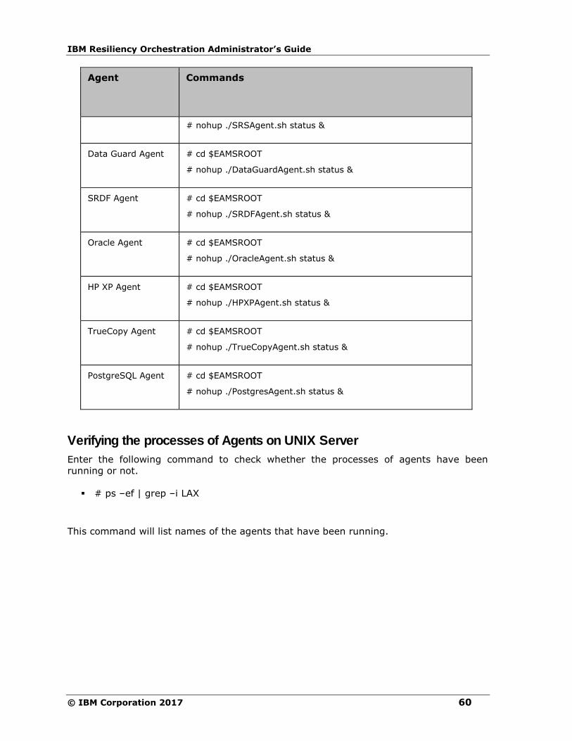
IBM Resiliency Orchestration Administrator’s Guide
© IBM Corporation 2017 60
Agent
Commands
# nohup ./SRSAgent.sh status &
Data Guard Agent # cd $EAMSROOT
# nohup ./DataGuardAgent.sh status &
SRDF Agent # cd $EAMSROOT
# nohup ./SRDFAgent.sh status &
Oracle Agent # cd $EAMSROOT
# nohup ./OracleAgent.sh status &
HP XP Agent # cd $EAMSROOT
# nohup ./HPXPAgent.sh status &
TrueCopy Agent # cd $EAMSROOT
# nohup ./TrueCopyAgent.sh status &
PostgreSQL Agent # cd $EAMSROOT
# nohup ./PostgresAgent.sh status &
Verifying the processes of Agents on UNIX Server
Enter the following command to check whether the processes of agents have been
running or not.
▪ # ps –ef | grep –i LAX
This command will list names of the agents that have been running.
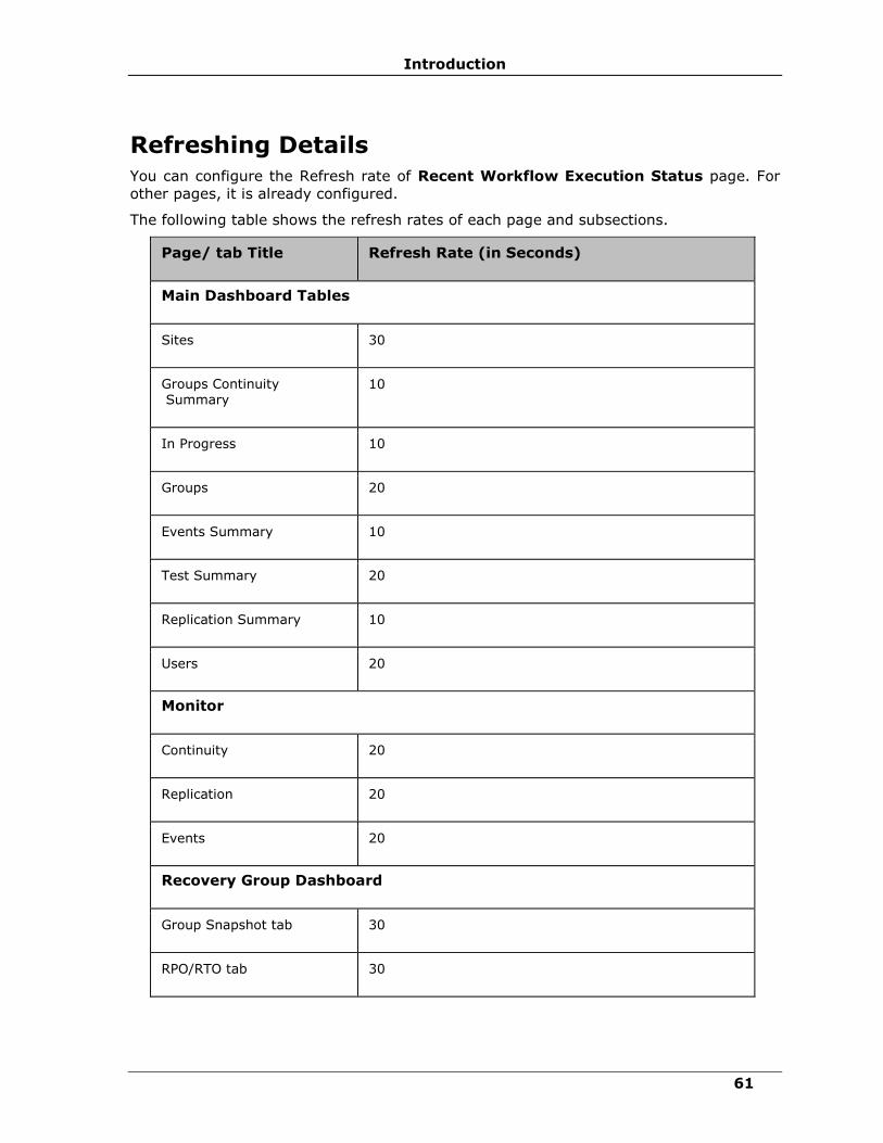
Introduction
61
Refreshing Details
You can configure the Refresh rate of Recent Workflow Execution Status page. For
other pages, it is already configured.
The following table shows the refresh rates of each page and subsections.
Page/ tab Title Refresh Rate (in Seconds)
Main Dashboard Tables
Sites 30
Groups Continuity Summary
10
In Progress 10
Groups 20
Events Summary 10
Test Summary 20
Replication Summary 10
Users 20
Monitor
Continuity 20
Replication 20
Events 20
Recovery Group Dashboard
Group Snapshot tab 30
RPO/RTO tab 30

IBM Resiliency Orchestration Administrator’s Guide
© IBM Corporation 2017 62
Page/ tab Title Refresh Rate (in Seconds)
Replication tab 30
Application Group Dashboard
Group Snapshot tab 8
Manage
Workflow List 10
Groups List 20
Manage Groups
Group Information tab 10
Normal Copy Advance Details section
4
Manage DR Solution tab 30
Manage Replication section 300
Recovery Workflows tab 300
Crash Recovery section 30
Drills
Drills 20
Group Workflow Listing 10
Test Exercise Dashboard 10
Reports
Reports Group List page 20
Discovery Sites
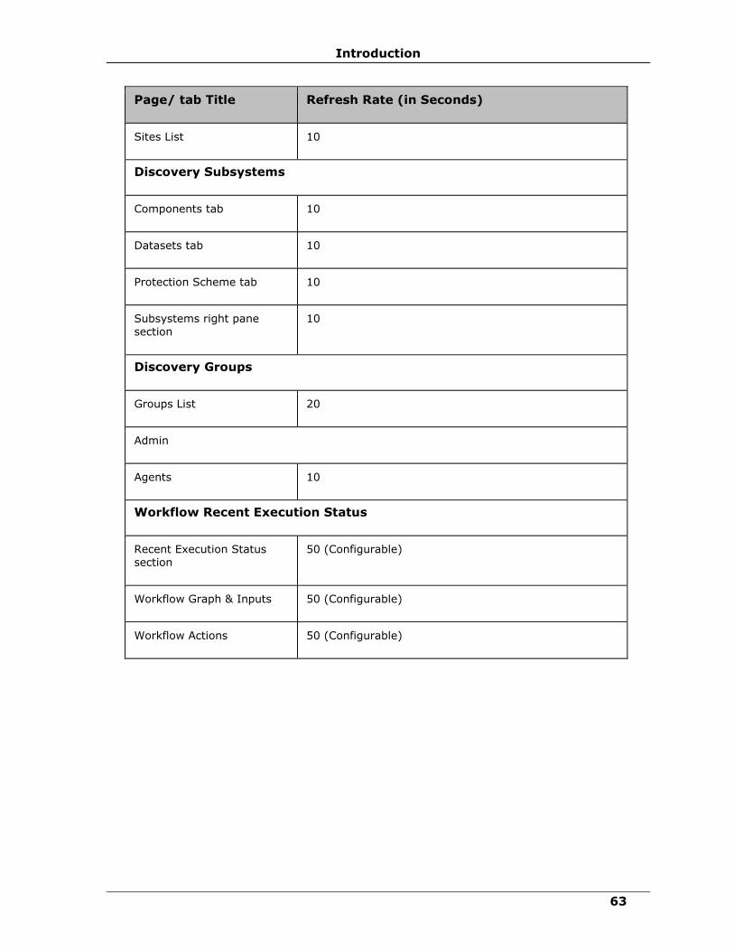
Introduction
63
Page/ tab Title Refresh Rate (in Seconds)
Sites List 10
Discovery Subsystems
Components tab 10
Datasets tab 10
Protection Scheme tab 10
Subsystems right pane section
10
Discovery Groups
Groups List 20
Admin
Agents 10
Workflow Recent Execution Status
Recent Execution Status section
50 (Configurable)
Workflow Graph & Inputs 50 (Configurable)
Workflow Actions 50 (Configurable)

IBM Resiliency Orchestration Administrator’s Guide
© IBM Corporation 2017 64
Configuration
Configuring IBM Resiliency Orchestration
On completing the installation, configure IBM Resiliency Orchestration in the following order:
Tomcat Configuration
Configuring Agents
Sites
User Management
Discover Subsystem
Notifications
Business Process Integration
Workflow Manager
Group Creation
Recovery Automation Library (RAL)
Agent Node Configuration
Vault Integration
Converged
ADC Profile
Tomcat Configuration
Steps to enable HTTPS in tomcat:
1. Go to the machine tomcat installation directory

Configuration
65
2. Default IBM ”keystoreFile/Password(Certificate)” is shipped with product.To use
Customer certificate, get keystore file and password from customer and modify
keystoreFile value with keystore file path and keystorePass value with password (check
yellow marks for place holders)
3. Open $TOMCAT_HOME/conf/server.xml
4. Search for below snippet of code if not available add the below
Connector port=“8443” protocol=“HTTP/1.1” maxHttpHeaderSize=“8192”
maxThreads=“150” minSpareThreads=“25” maxSpareThreads=“75”
enableLookups=“false” disableUploadTimeout=“true”
acceptCount=“100” scheme=“https” secure=“true”
clientAuth=“false” sslProtocol=“TLS”
keystoreFile="/$EAMSROOT/installconfig/keystore/sanovi.keystore”
keystorePass="^vMkT%678#4-06Gjue672Kwo95dzg” SSLEnabled=“true”/>
All panaces should be pointed to the Resiliency Orchestration installation directory.
If connecter is commented uncomment and restart tomcat server.
5. Restart the Tomcat.
Note
If the machine doesnot start, restart the panaces.
Steps to disable HTTP in tomcat
1. Open $TOMCAT_HOME/webapps/{webapp_to_diable_HTTP}/WEB-INF/web.xml Ex:
$EAMSROOT/tomcat/webapps/PanacesGUI/WEB-INF/web.xml
2. Make sure redirectPort is set to HTTPS port.For example see the below snippets on
server.xml
<Connector port="8080" maxHttpHeaderSize="8192"
maxThreads="150" minSpareThreads="25" maxSpareThreads="75"
enableLookups="false" redirectPort="8443" acceptCount="100"
connectionTimeout="20000" disableUploadTimeout="true" URIEncoding="utf-8"
/>
<Connector port="8443" maxHttpHeaderSize="8192"
maxThreads="150" minSpareThreads="25" maxSpareThreads="75"
enableLookups="false" disableUploadTimeout="true"
acceptCount="100" scheme="https" secure="true"

IBM Resiliency Orchestration Administrator’s Guide
© IBM Corporation 2017 66
clientAuth="false" sslProtocol="TLS"
keystoreFile="/opt/panaces/installconfig/keystore/IBM.keystore"
keystorePass="IBM"/>
3. Add below snippet of code after all Mappings
<security-constraint>
<web-resource-collection>
<web-resource-name>Entire Application</web-resource-name>
<url-pattern>/*</url-pattern>
</web-resource-collection>
<user-data-constraint>
<transport-guarantee>CONFIDENTIAL</transport-guarantee>
</user-data-constraint>
</security-constraint>
This code will automatically redirect all HTTP requests to HTTPS. This setting is per web
application.
Steps to change the port numbers 8080 or 8443 to different ones
1. Open $TOMCAT_HOME/conf/server.xml
2. Search for Connector and change port number. Port number should be in range of 1025
to 65535. For example see below snippet
<Connector port="8081" maxHttpHeaderSize="8192"
maxThreads="150" minSpareThreads="25" maxSpareThreads="75"
enableLookups="false" redirectPort="8443" acceptCount="100"
connectionTimeout="20000" disableUploadTimeout="true"
URIEncoding="utf-8" />
3. Before changing the port check/confirm is Firewall/IDS is not blocking the port and not
used by other application running on same server.
Steps to Enable Compression in Tomcat Server
Below tag in the server.xml enables compression.
Note:
Compression will be enabled if the file size is more than 2KB.

Configuration
67
Connector port=“8080” maxHttpHeaderSize=“8192”
maxThreads=“150” minSpareThreads=“25” maxSpareThreads=“75”
enableLookups=“false” redirectPort=“8443” acceptCount=“100”
compressionMinSize=“2048”
compression=“on”
compressableMimeType=“text/html,text/xml,text/plain,text/css, text/javascript,text/json,application/x-javascript,
application/javascript,application/json”
connectionTimeout=“20000” disableUploadTimeout=“true”
URIEncoding=“utf-8” />
<Connector port=“8443” maxHttpHeaderSize=“8192”
maxThreads=“150” minSpareThreads=“25” maxSpareThreads=“75”
enableLookups=“false” disableUploadTimeout=“true”
acceptCount=“100” scheme=“https” secure=“true”
compressionMinSize=“2048”
compression=“on”
compressableMimeType=“text/html,text/xml,text/plain,text/css,
text/javascript,text/json,application/x-javascript,
application/javascript,application/json”
clientAuth=“false” sslProtocol=“TLS”
keystoreFile="/opt/panaces/installconfig/keystore/IBM.keystore”
keystorePass=“IBM”/>
To start/ stop tomcat outside panaces script, follow the procedure below:
1. Change directory to $TOMCAT_HOME/bin
2. Run startup.sh/startup.bat depending on OS to start the server
3. Run shutdown.sh/shutdown.bat deepening on OS to stop the server
4. If tomcat is started using step 2, have to be stopped with step 3 only. Panaces script
can’t be used to stop tomcat.
Tomcats logs rotation
For Tomcat logs (catalina.out) rotation, follow the procedure below:
1. Create this file /etc/logrotate.d/tomcat
2. Copy the following contents into the above file.
$TOMCAT_HOME/logs/catalina.out {
copytruncate
daily
rotate 7
compress
missingok
size 10M
}
3. Run the following command to run the cron job manually
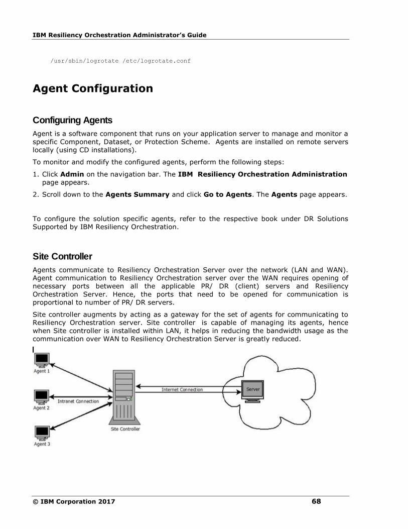
IBM Resiliency Orchestration Administrator’s Guide
© IBM Corporation 2017 68
/usr/sbin/logrotate /etc/logrotate.conf
Agent Configuration
Configuring Agents
Agent is a software component that runs on your application server to manage and monitor a
specific Component, Dataset, or Protection Scheme. Agents are installed on remote servers
locally (using CD installations).
To monitor and modify the configured agents, perform the following steps:
1. Click Admin on the navigation bar. The IBM Resiliency Orchestration Administration
page appears.
2. Scroll down to the Agents Summary and click Go to Agents. The Agents page appears.
To configure the solution specific agents, refer to the respective book under DR Solutions
Supported by IBM Resiliency Orchestration.
Site Controller
Agents communicate to Resiliency Orchestration Server over the network (LAN and WAN).
Agent communication to Resiliency Orchestration server over the WAN requires opening of
necessary ports between all the applicable PR/ DR (client) servers and Resiliency
Orchestration Server. Hence, the ports that need to be opened for communication is
proportional to number of PR/ DR servers.
Site controller augments by acting as a gateway for the set of agents for communicating to
Resiliency Orchestration server. Site controller is capable of managing its agents, hence
when Site controller is installed within LAN, it helps in reducing the bandwidth usage as the
communication over WAN to Resiliency Orchestration Server is greatly reduced.

Configuration
69
There are multiple supported configurations for site controller, they are:
1. Agents are configured to run locally – the agents are configured to communicate to a Site
controller and all the deployed site controller(s) are configured to communicate to
Resiliency Orchestration Server. Since Site controller acts as a gateway, ports for agent
communication needs to be opened between Site controller and Resiliency Orchestration
Server. Hence the ports that need to be opened is proportional to the number of SC
Server(s).
For Example: Site controller-PR is the Site controller on Primary and Resiliency Orchestration
is running on DR site. All the agents on primary are installed on PR Servers. The agents
leverage Site controller-PR for communication to Resiliency Orchestration, while Site
controller-PR will manage the health of the agents.
i. In the absence of Site controller, agent communication ports between every
PR/ DR server and Resiliency Orchestration Server needs to be opened over
WAN.
ii. With Site controller, only agent communication ports between Site controller-
PR and Resiliency Orchestration Server needs to be opened over WAN. The ports
for communication of agents and Site controller-PR needs to be opened but only
over LAN.
2. Agents Run remotely on Site Controller Server (s) – The Site controller augments
Agent Node functionality by acting as a gateway for all the agents running on that agent
node. This brings the advantages of remote agent, agent node and Site controller
together.
Example: Site controller-PR is the Site controller on Primary and Resiliency Orchestration is
running on DR site. All the agents on primary are installed on the same Site controller
Server. The agents leverage Site controller-PR for communication to Resiliency
Orchestration, while Site controller-PR will manage the health of the agents.
i. In the absence of Site controller, with dedicated Agent Node, agent communication
ports between the Agent Node and Resiliency Orchestration needs to be opened.
However, Resiliency Orchestration will manage the health of the agents over WAN.
ii. With Site controller, while only agent communication ports between Site controller-
PR and Resiliency Orchestration Server needs to be opened over WAN, the health of
agents is managed by Site controller and not by Resiliency Orchestration. Thus
reducing the network usage over WAN.
3. Some agents are local and some agents are remote (mixed) – this is combination of
above two deployment models.
Adding Site Controller to Resiliency Orchestration Server
CLI tool is introduced to add Site Controller details to Resiliency Orchestration Server. The
CLI tool used is: DRMSiteController.sh and is located in $EAMSROOT/cli.
Follow the commands to execute in the CLI:

IBM Resiliency Orchestration Administrator’s Guide
© IBM Corporation 2017 70
1. Login into IBM Resiliency Orchestration Server (Linux Server) and open a command
terminal.
2. Run $EAMSROOT/cli/>sh DRMSiteController.sh
OR
$EAMSROOT/cli/>./DRMSiteController.sh
1. Upon running the script, Sitecontroller prompt will be displayed: Sitecontroller>
2. Type the following syntax to add SiteController:
add sitecontroller -a <SiteController IPAddress> -n <Name of the Sitecontroller>
For example:
Sitecontroller>add sitecontroller -a 192.168.20.18 -n SC18
1. Press Enter.
Deleting SiteController from Resiliency Orchestration Server
CLI tool is used to delete Site Controller details to Resiliency Orchestration Server. The CLI
tool used is :DRMSiteController.sh and is located in $EAMSROOT/cli.
Follow the commands to execute in the CLI:
1. Login into IBM Resiliency Orchestration Server (Linux Server) and open a command
terminal.
2. Run $EAMSROOT/cli/>sh DRMSiteController.sh
OR
$EAMSROOT/cli/>./DRMSiteController.sh
3. Upon running the script, Sitecontroller prompt will be displayed: Sitecontroller>
4. Type the following syntax to add SiteController:
delete sitecontroller -a <SiteController IPAddress>
For example:
Sitecontroller>delete sitecontroller -a 192.168.20.18
5. Press Enter.

Configuration
71
Agentless
IBM Resiliency Orchestration software support Agentless model where user need not install
and run any Resiliency Orchestration specific software component on their data/ application
servers. Resiliency Orchestration software accesses the customer servers using Industry
standard remote access mechanism like SSH/ WMI/ JDBC.
Note:
▪ Agentless model is not supported for DB2, Sybase and SRS solutions.
▪ For remote agents: Create IBM Resiliency Orchestration node component as local.
▪ When we invoke a command from RAL into Resiliency Orchestration in the Agentless
model, we do not load the bash profile.
Example: If you set the Environmental variable, then the value of variable will not
appear.
▪ Command configuration in RAL with relative path will not work.
Pre- requisites
The target system should meet the following pre-requisites for IBM Resiliency Orchestration
to work in Agentless model:
Enabling SSH on Unix/Linux subsystem
1. Firewall setting: ssh port should be open for access from Resiliency Orchestration Server.
2. ssh server should be running on target server that allows connections from Resiliency
Orchestration Server for the configured user.
3. Sftp module should be enabled for ssh. Sftp module can be enabled by editing a file in
the operating system.
For example, in Linux edit /etc/ssh/sshd_config by un-commenting line 'Subsystem sftp
/usr/libexec/openssh/sftp-server, execute command service sshd reload.
Enabling WMI on Windows subsystem (High level)
1. Add permissions for Administrator (WMI user) at Component Services >
Computers > My Computer > COM Security (command: dcomcnfg)
2. Add permissions for Administrator (WMI User) at WMI Control > Security > Root >
CIMV2 > Security (command: wmimgmt.msc)
3. Modify Registry:
▪ For HKEY_CLASSES_ROOT > CLSID > {76A64158-CB41-11D1-8B02-
00600806D9B6}, create String AppID with value as {76A64158-CB41-11D1-
8B02-00600806D9B6}

IBM Resiliency Orchestration Administrator’s Guide
© IBM Corporation 2017 72
▪ For HKEY_CLASSES_ROOT > AppID Create Key {76A64158-CB41-11D1-8B02-
00600806D9B6}
▪ For the created Key, in the right hand pane - create empty String DllSurrogate.
4. Open Ports between Resiliency Orchestration Server and Windows Servers.
▪ Open Ports 135, 137, 138, 139, 445 and Port Range 49152-65535 [No reboot
required].
▪ If you don’t want to open Port Range 49152-65535, then you can also open
range say 50000-50200,as IBM may use 5-10 ports max in parallel, however
many Microsoft services (like Active Directory/ file sharing/ named pipes etc.)
uses RPC extensively and hence good range is required. And to configure this
custom range you need to change registry and server reboot is required.
Enabling WMI on Windows subsystem (Detailed information):
i. A user should have local administrative and domain account privileges for the
managed Server
ii.DCOM setting on managed Server should be configured for the given user list, having
remote access to WMI services. For Connecting to WMI on Remote Computer
details, follow link - http://msdn.microsoft.com/en-
us/library/aa389290%28v=VS.85%29.aspx
iii.Changes required for CIM namespaces.
▪ Add access for the given user to root/ CIMV2 namespace.
▪ Execute Method privilege should be enabled for the given user account.
i.Details of how to configure them are at Setting Namespace Security with the WMI
Control - http://msdn.microsoft.com/en-
us/library/aa393613%28v=VS.85%29.aspx
ii.Firewall setting
▪ Open port WMI port (default 135) in firewall, if the firewall is present.
▪ Details of how to do it are given at Connecting Through Windows Firewall -
http://msdn.microsoft.com/en-us/library/aa389286%28VS.85%29.aspx
iii. Windows - WMI Remote command execution:
▪ All setting as described in Windows WMI setting.
▪ Firewall Setting:
▪ Open port 135, 137,138,139,445 and range 49152-65535 (tcp/ udp) in firewall
configuration if firewall is present.
▪ The given user account should have Execute Method and Remote Enable
permissions for root\cimv2. [Setting Namespace Security with the WMI
Control – http://msdn.microsoft.com/en-
us/library/aa393613%28v=VS.85%29.aspx

Configuration
73
vi. Required Registry Changes: This step is applicable only for Windows 2008
onwards.
Note
Administrator user requires taking ownership to perform registry
operation for CLSID/AppID. Please refer procedure at Change/Replace
Ownership
1. Start > Run > regedit. The Registry Editor screen appears.
2. Perform below operations:
▪ At HKEY_CLASSES_ROOT , Select CLSID ,
▪ Select key {76A64158-CB41-11D1-8B02-00600806D9B6}
▪ In the right hand pane right click and select New > String Value. String name as
AppID with value as {76A64158-CB41-11D1-8B02-00600806D9B6}
▪ At HKEY_CLASSES_ROOT , Select AppID ,
▪ Create key as {76A64158-CB41-11D1-8B02-00600806D9B6} if it’s not present.
▪ Select created key {76A64158-CB41-11D1-8B02-00600806D9B6} then In the
right hand pane, right click and select New > String Value as DllSurrogate with
empty value (ie. Value Data should be empty.
i.This step is applicable only for Windows 2008 onwards. When the user is not a
domain or built-in Administrator user, the following steps has to done:
Note:
There is a difference between Administrator and users even in Administrators built-in group
for the UAC (User Account Control) feature in Windows Vista and Windows Server 2008.
Under UAC, accounts in the local Administrators group have two access tokens, standard
user and administrator privileges. Because of UAC access token filtering, a remote WMI
query is always run under the standard user token. So for a computer in workgroup, even if
the account is in the Administrators group, UAC filtering means that a script runs as a
standard user. A best practice is to create a dedicated local user account on the target
computer with explicit DCOM and WMI namespace access rights granted specifically for
remote connections (Microsoft Developer Network website).
To connect remotely to DCOM, follow the below steps:
1. Start > run > dcomcnfg. The Component Services page appears.
2. Expand Component Services > Computers.
3. Right click om My Computer > select Properties. The My Computer Properties
window appears.
4. Click the COM Security tab and in Launch and Activation Permissions section do
the following:
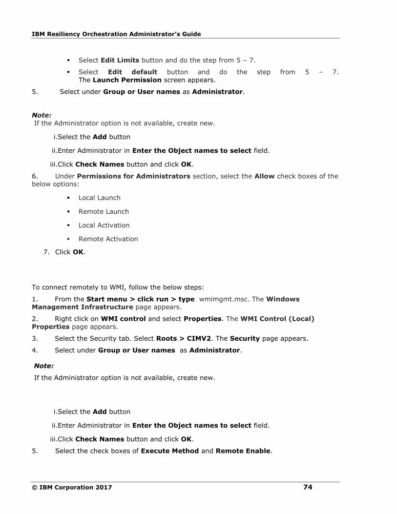
IBM Resiliency Orchestration Administrator’s Guide
© IBM Corporation 2017 74
▪ Select Edit Limits button and do the step from 5 – 7.
▪ Select Edit default button and do the step from 5 – 7.
The Launch Permission screen appears.
5. Select under Group or User names as Administrator.
Note:
If the Administrator option is not available, create new.
i.Select the Add button
ii.Enter Administrator in Enter the Object names to select field.
iii.Click Check Names button and click OK.
6. Under Permissions for Administrators section, select the Allow check boxes of the
below options:
▪ Local Launch
▪ Remote Launch
▪ Local Activation
▪ Remote Activation
7. Click OK.
To connect remotely to WMI, follow the below steps:
1. From the Start menu > click run > type wmimgmt.msc. The Windows
Management Infrastructure page appears.
2. Right click on WMI control and select Properties. The WMI Control (Local)
Properties page appears.
3. Select the Security tab. Select Roots > CIMV2. The Security page appears.
4. Select under Group or User names as Administrator.
Note:
If the Administrator option is not available, create new.
i.Select the Add button
ii.Enter Administrator in Enter the Object names to select field.
iii.Click Check Names button and click OK.
5. Select the check boxes of Execute Method and Remote Enable.

Configuration
75
6. Click OK.
Change/ Replace Ownership:
Administrator user requires taking ownership to perform registry operation for
CLSID/AppID. If user is unable to create Strings for CLSID keys, do the following( for
AppID follow same)
1. Start > run > regedit. The Registry Editor page appears.
2. HKEY_CLASSES_ROOT > CLSID > {76A64158-CB41-11D1-8B02-
00600806D9B6}.
3. In the right hand pane, right click New > String Value.
Note:
If you get an error message displaying “Error creating value”, do the following:
▪ Select the key value {76A64158-CB41-11D1-8B02-00600806D9B6} > Right
click > Permissions. The Permission screen appears.
▪ Under Security tab, select Administrator and select Advanced button.
Note:
If the Administrator option is not available, create new.
▪ Select the Add button
▪ Enter Administrator in Enter the Object names to select field.
▪ Click Check Names button and click OK.
▪ Double click on Administrator. The Advanced Security Settting window appears.
▪ Go to Owner tab, select the Administator in Change owner to section.
▪ Select Replace owners and subcontainers in objects checkbox and click OK.
1.
Open Custom Range of ports WMI/ RPC :
To enable WMI, we need to have open ports between 49152-65535. If you don’t want to
open the full range, then you can also configure in Registry Editor with specific range
example: 50000-50100 ( this will be used for any RPC ,WMI etc)
In Windows Server 2008 and later versions ,and in Windows Vista and later versions, the
default dynamic port range changed to the Start port: 49152 - End port: 65535
Note:
If your computer network environment uses only Windows Server 2012, Windows Server
2008 R2, Windows Server 2008, Windows 8, Windows 7 or Windows Vista, you must enable
connectivity over the high port range from 49152-65535.
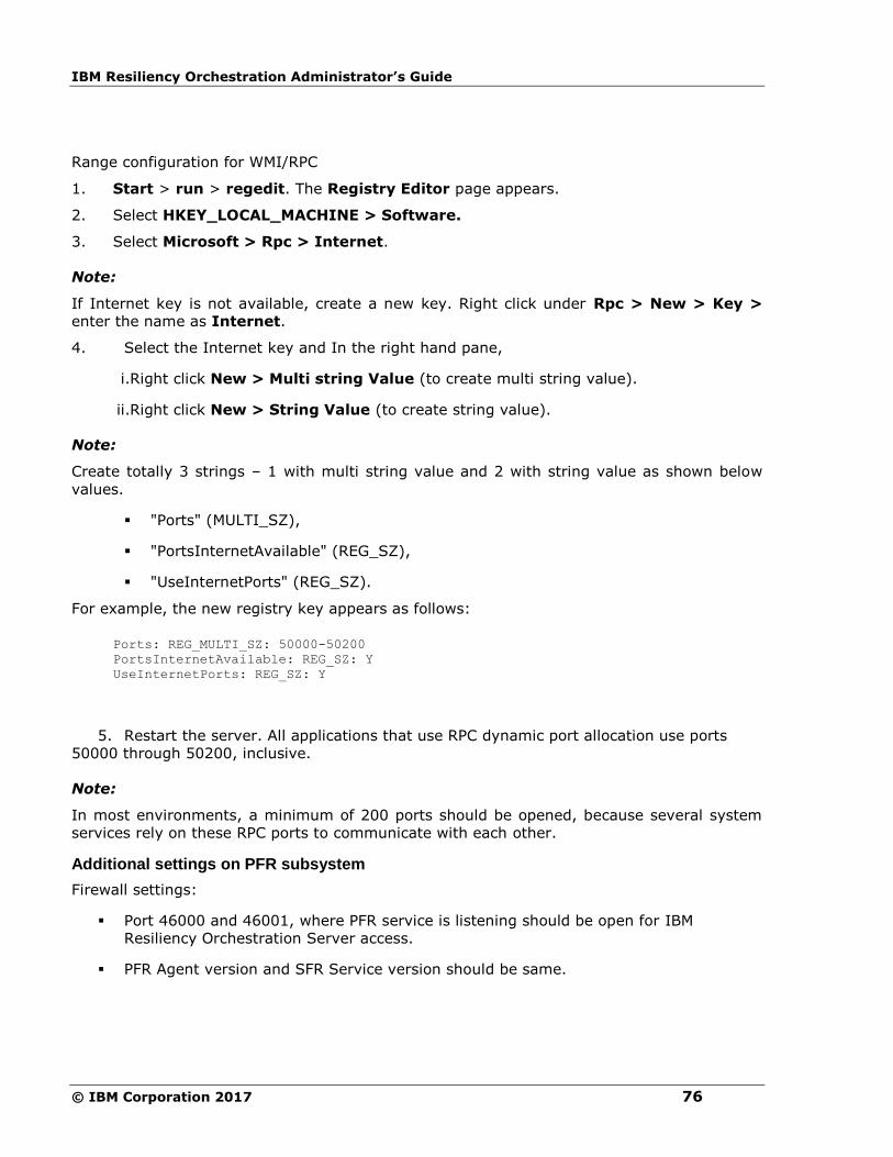
IBM Resiliency Orchestration Administrator’s Guide
© IBM Corporation 2017 76
Range configuration for WMI/RPC
1. Start > run > regedit. The Registry Editor page appears.
2. Select HKEY_LOCAL_MACHINE > Software.
3. Select Microsoft > Rpc > Internet.
Note:
If Internet key is not available, create a new key. Right click under Rpc > New > Key >
enter the name as Internet.
4. Select the Internet key and In the right hand pane,
i.Right click New > Multi string Value (to create multi string value).
ii.Right click New > String Value (to create string value).
Note:
Create totally 3 strings – 1 with multi string value and 2 with string value as shown below
values.
▪ "Ports" (MULTI_SZ),
▪ "PortsInternetAvailable" (REG_SZ),
▪ "UseInternetPorts" (REG_SZ).
For example, the new registry key appears as follows:
Ports: REG_MULTI_SZ: 50000-50200
PortsInternetAvailable: REG_SZ: Y
UseInternetPorts: REG_SZ: Y
5. Restart the server. All applications that use RPC dynamic port allocation use ports
50000 through 50200, inclusive.
Note:
In most environments, a minimum of 200 ports should be opened, because several system
services rely on these RPC ports to communicate with each other.
Additional settings on PFR subsystem
Firewall settings:
▪ Port 46000 and 46001, where PFR service is listening should be open for IBM
Resiliency Orchestration Server access.
▪ PFR Agent version and SFR Service version should be same.
Configuration
77
Configuration
When Agentless model is used,Resiliency Orchestration software needs additional
configuration.
As part of subsystem discovery, user needs to provide additional information which is used to
access customer servers remotely. This include credential information to access a customer
server. These are described in subsystem discovery page in detail.
If multiple servers can be accessed using same credential information, Resiliency
Orchestration provides option to enter the credentials once and then can be attached to any
number of subsystems. This is explained under Credentials.
To use IBM Resiliency Orchestration as an Agentless model, user needs to discover
Resiliency Orchestration server machine as a component and start an agent on the Resiliency
Orchestration server system.
Refer Management, to start agent and refer Configuration, to discover a component. Once
this step is done, user can go ahead with other subsystems and group discovery.

IBM Resiliency Orchestration Administrator’s Guide
© IBM Corporation 2017 78
Monitoring
When Agentless model is used, Resiliency Orchestration software provides additional
monitoring.
IBM Resiliency Orchestration software keeps monitoring the credential information and
inform user about failure by raising alerts and changing the status. Following events are
raised to indicate the change in credential status.
Event ID Event Description Event Impact
LoginFailedOnDRServer
Login failing on DR Server
Recovery and Monitoring may be impacted
LoginFailedOnPrimaryServer Login failing on Primary Server
Recovery and Monitoring may be impacted
LoginSuccessOnDRServer Login Success on DR Server
Recovery and Monitoring will work normally
LoginSuccessOnPrimaryServer Login Success on Primary Server
Recovery and Monitoring will work normally
PrimaryServerAccessible Primary Server is accessible
Recovery and Monitoring will work normally
PrimaryServerNotAccessible Unable to connect to Primary Server
Recovery and Monitoring may be impacted
DRServerAccessible DR Server is accessible Recovery and Monitoring will work normally
DRServerNotAccessible Unable to connect to DR Server
Recovery and Monitoring may be impacted
The status of the credentials are shown for each subsystem at subsystem listing page or
subsystem details page. Click Discover>Subsystems to view the credentials.
Following icons displays the credential status:
Configuration
79
- given credentials are good.
- given credentials are failing.
N.A - Not applicable – when agent run locally or credentials not required for technology.
Unknown – Initial status or when no credentials are provided.
Note:
If the target system is down or agent is down, the credential status will remain last known
status.
Management
When Agentless model is used, Resiliency Orchestration software provides additional Agent
management.
1. At any point of time or for maintenance, user can stop/start Agents as follows:
2. Click Admin on the navigation bar. The IBM Resiliency Orchestration
Administration page appears.
3. Scroll down to the Agents Summary and click Go to Agents. The Agents page
appears.
4. Click Stop/ Start button for the required Subsystem.
No further call will go to target server after stopping the Agent for the server. User will get
alert message saying "agent managing the subsystem is down/ up" depending on Stop/ Start
option.
Note:
Start / Stop all the Agents individually for a component.
User can also start and stop these processes using command line. Go to $EAMSROOT/bin
and enter the following command:
Servers
Commands
SOLARIS Go to $EAMSROOT/bin
> SolarisOSAgent.sh <start|stop> <ip address> SOLARISSERVER
LINUX # cd $EAMSROOT/bin
> LinuxOSAgent.sh <start|stop> <ip address> LINUXSERVER
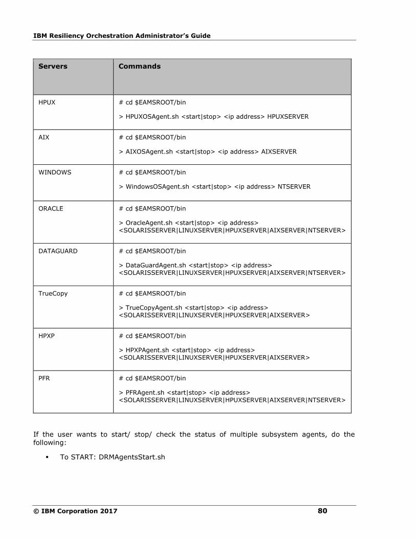
IBM Resiliency Orchestration Administrator’s Guide
© IBM Corporation 2017 80
Servers
Commands
HPUX
# cd $EAMSROOT/bin
> HPUXOSAgent.sh <start|stop> <ip address> HPUXSERVER
AIX # cd $EAMSROOT/bin
> AIXOSAgent.sh <start|stop> <ip address> AIXSERVER
WINDOWS # cd $EAMSROOT/bin
> WindowsOSAgent.sh <start|stop> <ip address> NTSERVER
ORACLE # cd $EAMSROOT/bin
> OracleAgent.sh <start|stop> <ip address>
<SOLARISSERVER|LINUXSERVER|HPUXSERVER|AIXSERVER|NTSERVER>
DATAGUARD # cd $EAMSROOT/bin
> DataGuardAgent.sh <start|stop> <ip address> <SOLARISSERVER|LINUXSERVER|HPUXSERVER|AIXSERVER|NTSERVER>
TrueCopy # cd $EAMSROOT/bin
> TrueCopyAgent.sh <start|stop> <ip address> <SOLARISSERVER|LINUXSERVER|HPUXSERVER|AIXSERVER>
HPXP # cd $EAMSROOT/bin
> HPXPAgent.sh <start|stop> <ip address> <SOLARISSERVER|LINUXSERVER|HPUXSERVER|AIXSERVER>
PFR # cd $EAMSROOT/bin
> PFRAgent.sh <start|stop> <ip address>
<SOLARISSERVER|LINUXSERVER|HPUXSERVER|AIXSERVER|NTSERVER>
If the user wants to start/ stop/ check the status of multiple subsystem agents, do the
following:
▪ To START: DRMAgentsStart.sh

Configuration
81
This can be used to start multiple agents as specified by options. The options arguments are
described in the table below. This is primarily used during patch process. This command start
agents that are currently not running and user has not specifically stopped it (User has
stopped the agent from GUI).
DRMAgentsStart.sh <option1> [option2 option3 ...]
example: > DRMAgentsStart.sh WINDOWSOS LINUXOS
▪ To STOP: DRMAgentsStop.sh
This can be used to stop multiple agents (remote agents) as specified by options. This is
primarily used during patch process.
DRMAgentsStop.sh <option1> [option2 option3 ...]
example: > DRMAgentsStop.sh WINDOWSOS LINUXOS
▪ To Check the Status: DRMAgentsStatus.sh
User can use this to see the current status of agents according to the options specified.
DRMAgentsStatus.sh <option1> [option2 option3 ...]
example:> DRMAgentsStatus.sh WINDOWSOS LINUXOS
The "options" arguments can be one or many. The full list of options are listed in the table.
Resiliency Orchestration Agents
option argument
Description
WINDOWSOS All Windows OS.
LINUXOS All Linux OS agents.
AIXOS All AIX OS agents.
HPUXOS All HPUX OS agents.
SOLARISOS All Solaris OS agents.
OSAGENTS All OS agents.
ORACLE All Oracle dataset agents.

IBM Resiliency Orchestration Administrator’s Guide
© IBM Corporation 2017 82
Resiliency Orchestration Agents
option argument
Description
MSSQL All MSSQL dataset agents.
DATASETAGENTS All dataset agents.
PFR All PFR protection agents.
TRUECOPY All TrueCopyprotection agents.
DATAGUARD All Data Guard protection agents.
HPXP All HPXP protection agents.
PROTECTIONAGENTS All protection agents.
NETAPPONTAPOS All NetAppOnTAP OS agents.
PostgreSQL All PostgreSQL dataset agents.
MSExch All MS Exchange dataset agents.
ALL All OS agents, All dataset agents, All protection agents, ALL Management Service Agents.
NETAPP All NetApp protection agents.
SybaseASE - All Sybase dataset agents.
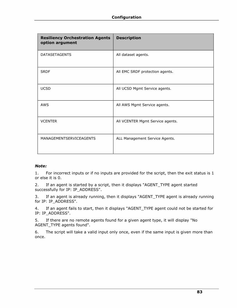
Configuration
83
Resiliency Orchestration Agents
option argument
Description
DATASETAGENTS All dataset agents.
SRDF All EMC SRDF protection agents.
UCSD All UCSD Mgmt Service agents.
AWS All AWS Mgmt Service agents.
VCENTER All VCENTER Mgmt Service agents.
MANAGEMENTSERVICEAGENTS ALL Management Service Agents.
Note:
1. For incorrect inputs or if no inputs are provided for the script, then the exit status is 1
or else it is 0.
2. If an agent is started by a script, then it displays "AGENT_TYPE agent started
successfully for IP: IP_ADDRESS".
3. If an agent is already running, then it displays "AGENT_TYPE agent is already running
for IP: IP_ADDRESS".
4. If an agent fails to start, then it displays "AGENT_TYPE agent could not be started for
IP: IP_ADDRESS".
5. If there are no remote agents found for a given agent type, it will display "No
AGENT_TYPE agents found".
6. The script will take a valid input only once, even if the same input is given more than
once.
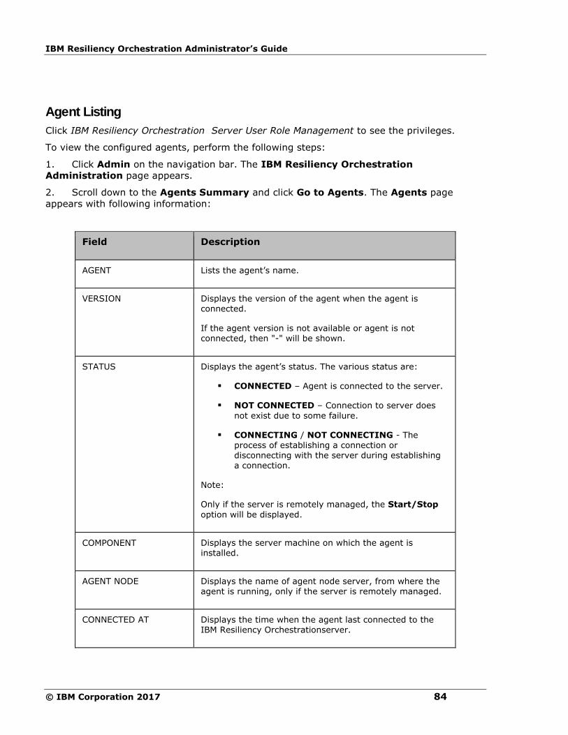
IBM Resiliency Orchestration Administrator’s Guide
© IBM Corporation 2017 84
Agent Listing
Click IBM Resiliency Orchestration Server User Role Management to see the privileges.
To view the configured agents, perform the following steps:
1. Click Admin on the navigation bar. The IBM Resiliency Orchestration
Administration page appears.
2. Scroll down to the Agents Summary and click Go to Agents. The Agents page
appears with following information:
Field Description
AGENT Lists the agent’s name.
VERSION Displays the version of the agent when the agent is connected.
If the agent version is not available or agent is not connected, then "-" will be shown.
STATUS
Displays the agent’s status. The various status are:
▪ CONNECTED – Agent is connected to the server.
▪ NOT CONNECTED – Connection to server does
not exist due to some failure.
▪ CONNECTING / NOT CONNECTING - The process of establishing a connection or disconnecting with the server during establishing a connection.
Note:
Only if the server is remotely managed, the Start/Stop
option will be displayed.
COMPONENT Displays the server machine on which the agent is installed.
AGENT NODE Displays the name of agent node server, from where the agent is running, only if the server is remotely managed.
CONNECTED AT Displays the time when the agent last connected to the IBM Resiliency Orchestrationserver.

Configuration
85
Field Description
The agent can be installed on more than one server machine. Click respective Agent link to
view agent details and statistics. In the right pane, you can view the Event Polling Interval
in seconds, configured for the respective agents.
The Agent Details page displays the following:
Agent Details
Agent Name Displays the Agent’s name.
Description Displays the description about the Agent.
Agent Version Displays the version of the agent when the agent is connected.
If the agent version is not available or agent is not connected, then "-" will be shown.
Status Displays the current status of the Agent.
Object Class
Displays whether the agent is related to a Component, Dataset, or Protection Scheme.
Object Type
Displays the type of the object that is being managed by the respective agent.
For example, if the Object class is ‘Component’, then this specifies whether the Components is of type ‘NT Server’ or ‘Solaris Server' etc.
IP Address
Displays the IP address of the server on which the agent is installed.
Time of Install
Displays the time of installation of the Agent on the server.
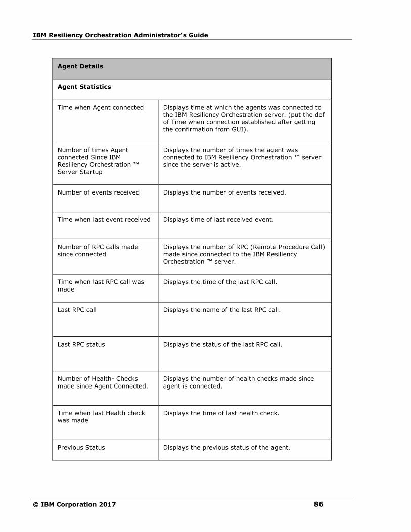
IBM Resiliency Orchestration Administrator’s Guide
© IBM Corporation 2017 86
Agent Details
Agent Statistics
Time when Agent connected Displays time at which the agents was connected to the IBM Resiliency Orchestration server. (put the def of Time when connection established after getting
the confirmation from GUI).
Number of times Agent connected Since IBM Resiliency Orchestration ™
Server Startup
Displays the number of times the agent was connected to IBM Resiliency Orchestration ™ server since the server is active.
Number of events received Displays the number of events received.
Time when last event received Displays time of last received event.
Number of RPC calls made since connected
Displays the number of RPC (Remote Procedure Call) made since connected to the IBM Resiliency
Orchestration ™ server.
Time when last RPC call was made
Displays the time of the last RPC call.
Last RPC call
Displays the name of the last RPC call.
Last RPC status
Displays the status of the last RPC call.
Number of Health- Checks made since Agent Connected.
Displays the number of health checks made since agent is connected.
Time when last Health check was made
Displays the time of last health check.
Previous Status Displays the previous status of the agent.
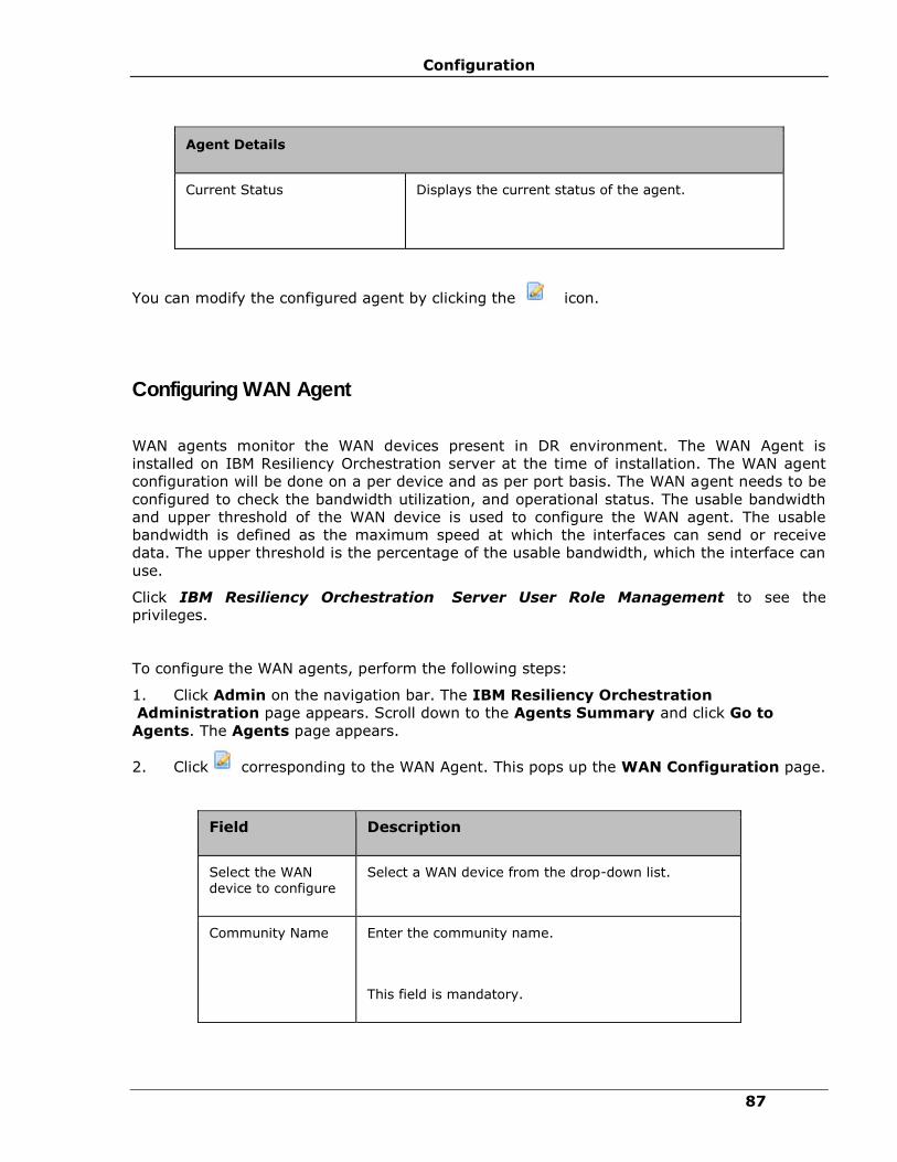
Configuration
87
Agent Details
Current Status
Displays the current status of the agent.
You can modify the configured agent by clicking the icon.
Configuring WAN Agent
WAN agents monitor the WAN devices present in DR environment. The WAN Agent is
installed on IBM Resiliency Orchestration server at the time of installation. The WAN agent
configuration will be done on a per device and as per port basis. The WAN agent needs to be
configured to check the bandwidth utilization, and operational status. The usable bandwidth
and upper threshold of the WAN device is used to configure the WAN agent. The usable
bandwidth is defined as the maximum speed at which the interfaces can send or receive
data. The upper threshold is the percentage of the usable bandwidth, which the interface can
use.
Click IBM Resiliency Orchestration Server User Role Management to see the
privileges.
To configure the WAN agents, perform the following steps:
1. Click Admin on the navigation bar. The IBM Resiliency Orchestration
Administration page appears. Scroll down to the Agents Summary and click Go to
Agents. The Agents page appears.
2. Click corresponding to the WAN Agent. This pops up the WAN Configuration page.
Field Description
Select the WAN device to configure
Select a WAN device from the drop-down list.
Community Name Enter the community name.
This field is mandatory.
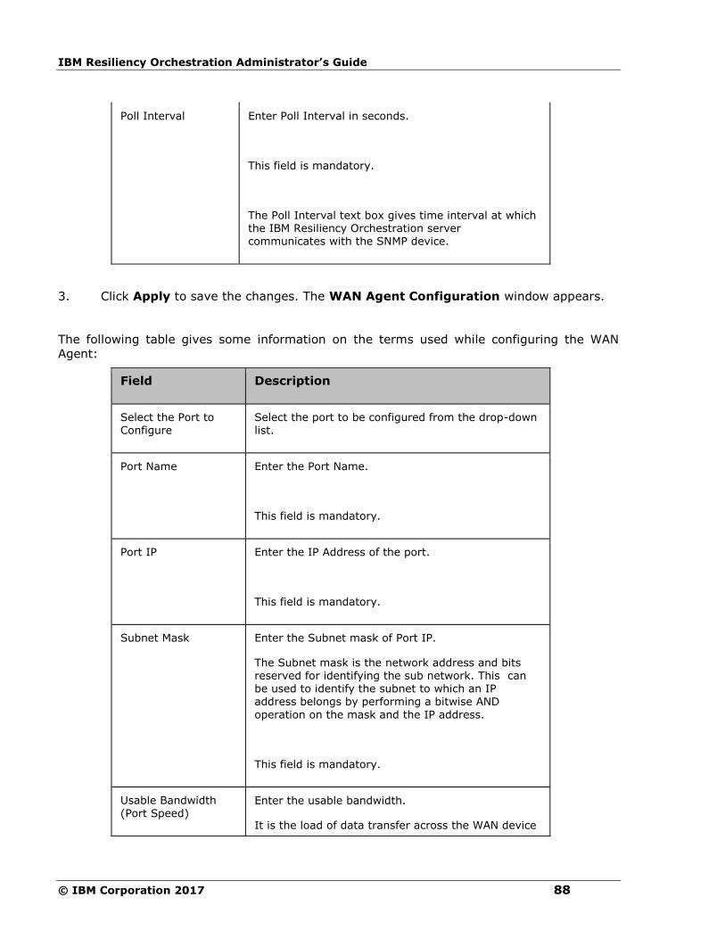
IBM Resiliency Orchestration Administrator’s Guide
© IBM Corporation 2017 88
Poll Interval Enter Poll Interval in seconds.
This field is mandatory.
The Poll Interval text box gives time interval at which the IBM Resiliency Orchestration server communicates with the SNMP device.
3. Click Apply to save the changes. The WAN Agent Configuration window appears.
The following table gives some information on the terms used while configuring the WAN
Agent:
Field Description
Select the Port to Configure
Select the port to be configured from the drop-down list.
Port Name Enter the Port Name.
This field is mandatory.
Port IP Enter the IP Address of the port.
This field is mandatory.
Subnet Mask Enter the Subnet mask of Port IP.
The Subnet mask is the network address and bits reserved for identifying the sub network. This can be used to identify the subnet to which an IP
address belongs by performing a bitwise AND
operation on the mask and the IP address.
This field is mandatory.
Usable Bandwidth (Port Speed)
Enter the usable bandwidth.
It is the load of data transfer across the WAN device
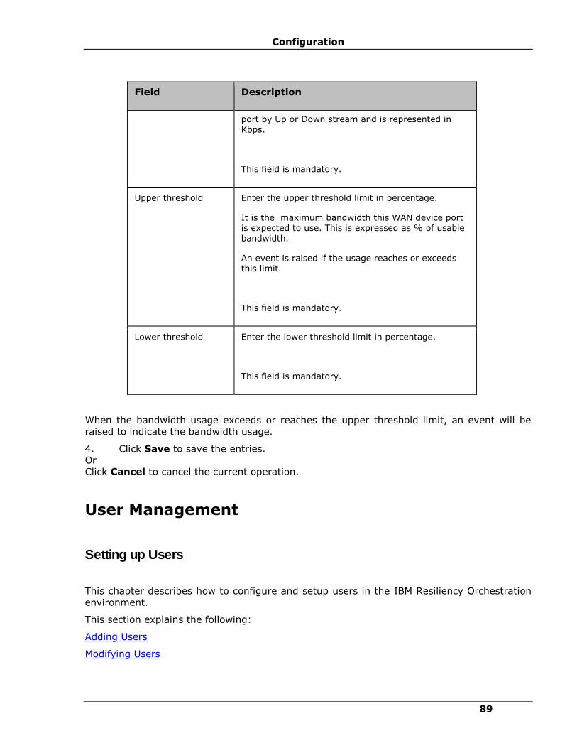
Configuration
89
Field Description
port by Up or Down stream and is represented in Kbps.
This field is mandatory.
Upper threshold
Enter the upper threshold limit in percentage.
It is the maximum bandwidth this WAN device port is expected to use. This is expressed as % of usable
bandwidth.
An event is raised if the usage reaches or exceeds this limit.
This field is mandatory.
Lower threshold Enter the lower threshold limit in percentage.
This field is mandatory.
When the bandwidth usage exceeds or reaches the upper threshold limit, an event will be
raised to indicate the bandwidth usage.
4. Click Save to save the entries.
Or
Click Cancel to cancel the current operation.
User Management
Setting up Users
This chapter describes how to configure and setup users in the IBM Resiliency Orchestration
environment.
This section explains the following:
Adding Users
Modifying Users

IBM Resiliency Orchestration Administrator’s Guide
© IBM Corporation 2017 90
Deleting Users
Setting System Options for Users
Basic User Role management
Adding Users
Click IBM Resiliency Orchestration Server User Role Management to see the privileges.
To add a new user, perform the following steps:
1. Click Admin on the navigation bar. The IBM Resiliency Orchestration
Administration page appears. Scroll down to the User Summary and click Go to Users.
The IBM Resiliency Orchestration Users page appears.
Note:
Only Super Administrator has the authority to add users.
2. Click Create New User at the top right corner of IBM Resiliency Orchestration
Users page. The Create New User page appears.
Create a user by providing following information. In this page the mandatory fields are
marked with a red asterisk. This window has details of the user along with their login
information (user name and password).
Field Description
Login Information
IBM Resiliency Orchestration ID
IBM Resiliency Orchestration ID is the IBM Resiliency Orchestration user name that you enter while logging into IBM Resiliency Orchestration.
▪ This field accepts up to 16 alphanumeric characters
and must begin with a letter.

Configuration
91
Field Description
Choose Password The password is used to authenticate the IBM Resiliency Orchestration user within IBM Resiliency Orchestration ™.
This field accepts up to 16 alphanumeric characters including at least one digit.
Note:
The password cannot contain the character patterns listed
below.
▪ <script>(.*?)</script>
▪ Src=*
▪ Eval
▪ Expression
▪ JavaScript
▪ VBScript
▪ Onload
▪ Iframe
▪ <*>
Password Strength When you type your password, the color of Password Strength changes.
This field displays any one of the following values - Weak/ Medium/ Good/ Strong.
Confirm Password Re-enter the password to confirm it.
User Details
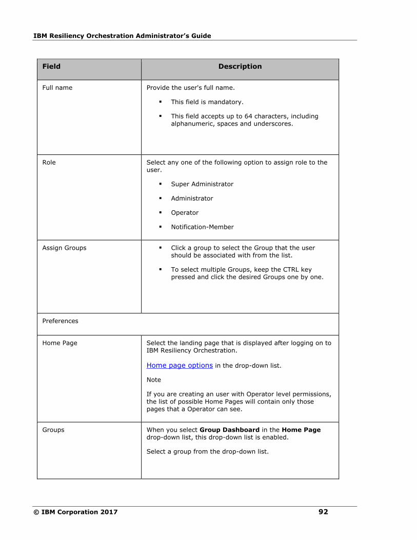
IBM Resiliency Orchestration Administrator’s Guide
© IBM Corporation 2017 92
Field Description
Full name Provide the user's full name.
▪ This field is mandatory.
▪ This field accepts up to 64 characters, including alphanumeric, spaces and underscores.
Role Select any one of the following option to assign role to the
user.
▪ Super Administrator
▪ Administrator
▪ Operator
▪ Notification-Member
Assign Groups
▪ Click a group to select the Group that the user should be associated with from the list.
▪ To select multiple Groups, keep the CTRL key pressed and click the desired Groups one by one.
Preferences
Home Page Select the landing page that is displayed after logging on to IBM Resiliency Orchestration.
Home page options in the drop-down list.
Note
If you are creating an user with Operator level permissions,
the list of possible Home Pages will contain only those pages that a Operator can see.
Groups When you select Group Dashboard in the Home Page drop-down list, this drop-down list is enabled.
Select a group from the drop-down list.

Configuration
93
Field Description
Professional Details
Company Name Enter the user company name.
This field accepts maximum of 255 characters.
Designation
Enter user designation.
This field accepts maximum of 255 characters.
Department
Enter user department.
This field accepts maximum of 255 characters.
Working hours, In Time Enter start time of the user working hours.
The time format is HH:MM:AM/ PM.
Working hours, Out Time Enter end time of the user working hours.
The time format is HH:MM:AM/ PM.
Contact Details
Address
Enter the contact address of the user.
This field accepts maximum of 255 characters.
Phone (1)
Enter the primary telephone number of the user.
This field accepts only numerals and allows up to 15 characters.
Phone (2) Enter the primary telephone number of the user.
This field accepts only numerals and allows up to 15 characters.
Mobile Enter the mobile number of the user.
This field accepts only numerals and allows up to 15 characters.

IBM Resiliency Orchestration Administrator’s Guide
© IBM Corporation 2017 94
Field Description
Pager Enter the pager number of the user.
This field accepts only numerals and allows up to 12 characters.
Enter the e-mail address of the user.
This accepts valid email addresses in the form of [email protected] (e.g., [email protected])
Mobile Email Enter the mobile e-mail address of the user.
This accepts alphanumeric characters, period mark and @ only.
Preferred Mode of Communication
Enter the mode of communication. The available choices are:
▪ Mobile
▪ Telephone
▪ Pager
Note
Based on your selection of above mentioned choices, make sure that appropriate values are specified in the associated fields.
3. Click Save to add the user.
OR
Click Cancel to quit current operation.
4. On successfully adding a user, a message box is displayed.
5. Click OK in the message box to return to the IBM Resiliency Orchestration Users
page.
Modifying Users
Click IBM Resiliency Orchestration Server User Role Management to see the privileges.

Configuration
95
To modify user details perform the following:
1. Click Admin on the navigation bar. The IBM Resiliency Orchestration Administration
page appears. Scroll down to the User Summary and click Go to Users. The IBM
Resiliency Orchestration Users page appears.
2. Click icon corresponding to the user whose details you want to modify. This opens Edit
User window. Change the required fields. Refer Adding Users for field description.
Note:
You cannot modify IBM Resiliency Orchestration ID.
3. Click Save to save the modifications.
OR
Click Cancel to quit current operation.
4. On successful modification, a message box indicating ‘User Modified Successfully’ is
displayed.
5. Click OK in the message box to return to the IBM Resiliency Orchestration Users
page.
Deleting Users
Click IBM Resiliency Orchestration Server User Role Management to see the privileges.
To delete a User perform the following steps:
1. Click Admin on the navigation bar. The IBM Resiliency Orchestration
Administration page appears. Scroll down to the User Summary and click Go to
Users. The IBM Resiliency Orchestration Users page appears.
2. Click icon corresponding to the user that you want to delete. A message box is
displayed confirming the deletion.
3. Click OK in the message box.
Note:
▪ You cannot delete a user with which you are currently logged in.
▪ Only Super Administrator has the authority to delete users.
Setting System Options for Users

IBM Resiliency Orchestration Administrator’s Guide
© IBM Corporation 2017 96
Super Administrator has the privileges to set default settings for users.
Click IBM Resiliency Orchestration Server User Role Management to see the privileges.
To establish settings for default users:
1. Click Admin on the navigation bar. The IBM Resiliency Orchestration
Administration page appears. Scroll down to the User Summary and click Go to
Users. The IBM Resiliency Orchestration Users page appears.
2. Click the Set System Options for Users link at the top right corner of the page. The
Set System Options for Users page appears.
Super Administrator can set the following privileges:
Field Description
Preferences
Home Page Select the landing page for all users that is displayed after logging on to IBM Resiliency
Orchestration.
Edit Options
User Details Select users who could be allowed to edit their own details.
Password
All User Passwords expire in Select the duration for the expiry of passwords.
a. Enter the numeral in the text box, and
b. Select the unit of time from the drop down. The available options are: Never, Days, Weeks,
and Months.
Note:
Select "Never" if you do not want the password to expire.
Notify User on Password expiry
(Days before)
Enter the number of days before expiry you want to notify the user regarding expiration of password.
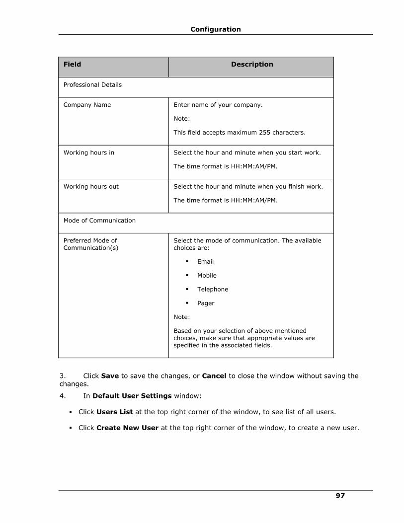
Configuration
97
Field Description
Professional Details
Company Name Enter name of your company.
Note:
This field accepts maximum 255 characters.
Working hours in Select the hour and minute when you start work.
The time format is HH:MM:AM/PM.
Working hours out Select the hour and minute when you finish work.
The time format is HH:MM:AM/PM.
Mode of Communication
Preferred Mode of Communication(s)
Select the mode of communication. The available choices are:
▪ Mobile
▪ Telephone
▪ Pager
Note:
Based on your selection of above mentioned choices, make sure that appropriate values are specified in the associated fields.
3. Click Save to save the changes, or Cancel to close the window without saving the
changes.
4. In Default User Settings window:
▪ Click Users List at the top right corner of the window, to see list of all users.
▪ Click Create New User at the top right corner of the window, to create a new user.

IBM Resiliency Orchestration Administrator’s Guide
© IBM Corporation 2017 98
Editing User Preferences
Click IBM Resiliency Orchestration Server User Role Management to see the privileges.
To edit user preferences:
1. Click Admin on the navigation bar. The IBM Resiliency Orchestration
Administration page appears. Scroll down to the User Summary and click Go to
Users. The IBM Resiliency Orchestration Users page appears.
2. Click User Preferences at the top right corner of the page. The Edit User
Preferences page appears.
3. Change the required fields.
Note:
You can change only your password and home page details.
4. Click Save to save the changes, or Cancel to close the window without saving the
changes.
Configuring LDAP
Note:
The steps provided below are regarding 389 Directory Structure on Fedora.
1. Install the LDAP Directory Server on the Linux machine.
2. Login to the Admin console of the Directory Server.
Creating custom Class and Attributes
A “Custom class” for holding IBM Resiliency Orchestration roles has to be created with
appropriate custom attributes. This custom class will be a child of the “groups” class.
1. Login to the LDAP server.
2. New custom attributes can be provided in the Schema tab.
The following attributes for IBM Resiliency Orchestration will have to be created with the type
Boolean:

Configuration
99
Attribute name Type
bp-edit Boolean
bp-execute Boolean
failover-edit Boolean
failover-execute Boolean
fallback-edit Boolean
fallback-execute Boolean
fallbackresync-edit Boolean
fallbackresync-execute Boolean
groups-edit Boolean
newdrill-edit Boolean
newdrill-execute Boolean
normalcopy-edit Boolean
normalcopy-execute Boolean
normalfullcopy-edit Boolean
normalfullcopy-execute
Boolean
policy-edit Boolean
policy-execute Boolean
reversenormalcopy-edit
Boolean
reversenormalcopy-execute
Boolean
switchback-edit Boolean
switchback-execute Boolean
switchover-edit Boolean
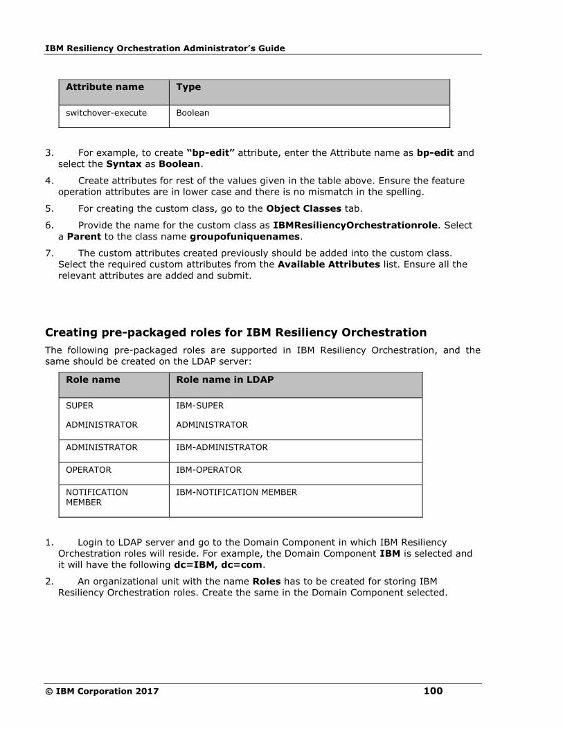
IBM Resiliency Orchestration Administrator’s Guide
© IBM Corporation 2017 100
Attribute name Type
switchover-execute Boolean
3. For example, to create “bp-edit” attribute, enter the Attribute name as bp-edit and
select the Syntax as Boolean.
4. Create attributes for rest of the values given in the table above. Ensure the feature
operation attributes are in lower case and there is no mismatch in the spelling.
5. For creating the custom class, go to the Object Classes tab.
6. Provide the name for the custom class as IBMResiliencyOrchestrationrole. Select
a Parent to the class name groupofuniquenames.
7. The custom attributes created previously should be added into the custom class.
Select the required custom attributes from the Available Attributes list. Ensure all the
relevant attributes are added and submit.
Creating pre-packaged roles for IBM Resiliency Orchestration
The following pre-packaged roles are supported in IBM Resiliency Orchestration, and the
same should be created on the LDAP server:
Role name Role name in LDAP
SUPER
ADMINISTRATOR
IBM-SUPER
ADMINISTRATOR
ADMINISTRATOR IBM-ADMINISTRATOR
OPERATOR IBM-OPERATOR
NOTIFICATION MEMBER
IBM-NOTIFICATION MEMBER
1. Login to LDAP server and go to the Domain Component in which IBM Resiliency
Orchestration roles will reside. For example, the Domain Component IBM is selected and
it will have the following dc=IBM, dc=com.
2. An organizational unit with the name Roles has to be created for storing IBM
Resiliency Orchestration roles. Create the same in the Domain Component selected.
Configuration
101
3. To create a new role, for example, a SUPER ADMINISTRATOR, go to the
organizational unit Roles created in the previous step and create a new object with the
type being IBMdrmrole. The role name should have the prefix “IBM-” to identify them
as roles created for IBM Resiliency Orchestration. For example, for a SUPER
ADMINISTRATOR role, enter group name as IBM-SUPER ADMINISTRATOR.
4. Users can be added to the newly created roles through the role properties.
5. Similarly add the other pre-packaged roles and the required users.
Note:
The role name format after the prefix should not contain hyphen. This is because the hyphen
is used as a delimiter to separate the role-prefix and the actual role name.
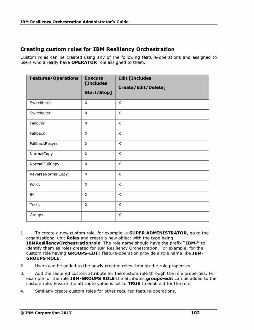
IBM Resiliency Orchestration Administrator’s Guide
© IBM Corporation 2017 102
Creating custom roles for IBM Resiliency Orchestration
Custom roles can be created using any of the following feature-operations and assigned to
users who already have OPERATOR role assigned to them.
Features/Operations Execute
[Includes
Start/Stop]
Edit [Includes
Create/Edit/Delete]
Switchback X X
Switchover X X
Failover X X
Fallback X X
FallbackResync X X
NormalCopy X X
NormalFullCopy X X
ReverseNormalCopy X X
Policy X X
BP X X
Tests X X
Groups X
1. To create a new custom role, for example, a SUPER ADMINISTRATOR, go to the
organisational unit Roles and create a new object with the type being
IBMResiliencyOrchestrationrole. The role name should have the prefix “IBM-” to
identify them as roles created for IBM Resiliency Orchestration. For example, for the
custom role having GROUPS-EDIT feature-operation provide a role name like IBM-
GROUPS ROLE.
2. Users can be added to the newly created roles through the role properties.
3. Add the required custom attribute for the custom role through the role properties. For
example for the role IBM-GROUPS ROLE the attributes groups-edit can be added to the
custom role. Ensure the attribute value is set to TRUE to enable it for the role.
4. Similarly create custom roles for other required feature-operations.
Configuration
103
Note:
The role name format after the prefix should not contain hyphen. This is because the hyphen
is used as a delimiter to separate the role-prefix and the actual role name.
External Directory Server Details
To view the External Directory Server Details for LDAP Server, perform the following steps:
1. Click Admin on the navigation bar. The IBM Resiliency Orchestration
Administration page appears. Scroll down to the Directory Server Details and click Go
to Directory Server Details. The External Directory Server Details page appears.
2. The LDAP Server can be selected and it has the following options:
i.Server URL
ii.Search Base for reading roles
User Account for reading directories
▪ User Name
▪ Password
Note:
If anonymous directory lookup is enabled, then the configured user for accessing the
directory server will be able to lookup the directory even if the credentials given are wrong.
LDAP Query
Roles are searched from the organizational unit ou=Roles
Users associated with the role are read by reading the attribute uniquemember from the
role.
Configuring AD
1. Login to the AD server.
2. An organizational unit with the name Roles has to be created for storing IBM
Resiliency Orchestration roles. Create the same in the required Domain Component.
3. Ensure the following tools are installed on the Advanced Directory server machine:
schmmgmt - Appendix A : Installation of schmmgmt tool on Active Directory machine.
ADSI Edit - Appendix B: Installation of ADSI Edit tool on Active Directory machine.

IBM Resiliency Orchestration Administrator’s Guide
© IBM Corporation 2017 104
Also the Unique X.500 Object Id for the machine running the AD server is required while
creating the
custom class and custom attributes.
Creating custom Class and Attributes
The schmmgmt tool will display the list of classes and attributes being loaded into the AD
server through the schema.
The following attributes for IBM Resiliency Orchestration will have to be created with the
type Boolean using the schmmgmt tool.
Attribute name Type
bp-edit Boolean
bp-execute Boolean
failover-edit Boolean
failover-execute Boolean
fallback-edit Boolean
fallback-execute Boolean
fallbackresync-edit Boolean
fallbackresync-execute Boolean
groups-edit Boolean
newdrill-edit Boolean
newdrill-execute Boolean
normalcopy-edit Boolean
normalcopy-execute Boolean
normalfullcopy-edit Boolean
normalfullcopy-execute
Boolean
policy-edit Boolean

Configuration
105
Attribute name Type
policy-execute Boolean
reversenormalcopy-edit
Boolean
reversenormalcopy-execute
Boolean
switchback-edit Boolean
switchback-execute Boolean
switchover-edit Boolean
switchover-execute Boolean
1. For example, to create bp-edit, the common name and LDAP Display name for
the attribute is bp-edit. Assign a Unique X500 Object ID for the attribute and ensure
syntax for the attribute is Boolean.
2. Similarly, create the custom attributes and ensure that each of these attributes use
a unique ending sequence number for the unique X500 Object ID.
3. Create a custom class in the schmmgmt window and provide common name and
LDAP Display name as IBM-role. Assign a Unique X500 Object ID for the class. Ensure
that cn is a Mandatory attribute in the custom class and all the IBM Resiliency
Orchestration relevant custom attributes as Optional attributes.
Creating pre-packaged roles for IBM Resiliency Orchestration
The following pre-packaged roles are supported in IBM Resiliency Orchestration, and the
same should be created on the AD server:
Role name Role name in AD
SUPER
ADMINISTRATOR
IBM-SUPER
ADMINISTRATOR
ADMINISTRATOR IBM-ADMINISTRATOR
OPERATOR IBM-OPERATOR
NOTIFICATION
MEMBER
IBM-NOTIFICATION
MEMBER

IBM Resiliency Orchestration Administrator’s Guide
© IBM Corporation 2017 106
1. The Adsiedit tool can be used to create pre-packaged roles.
All roles should have the prefix “IBM-” to identify them as roles created for IBM Resiliency
Orchestration.
2. To create a pre-packaged role, for example SUPER ADMINISTRATOR, create a new
object with type IBM-role. Provide cn and sAMAccountName as IBM-SUPER
ADMINISTRATOR
3. A user can be added to a role by adding it as a member of the role through its properties.
Similarly create the other pre-packaged roles.
Creating custom roles for IBM Resiliency Orchestration
Custom roles can be created using any of the following feature-operations and assigned to
users who already have OPERATOR role assigned to them.
Features/Operations Execute
[Includes
Start/Stop]
Edit [Includes
Create/Edit/Delete]
Switchback X X
Switchover X X
Failover X X
Fallback X X
FallbackResync X X
NormalCopy X X
NormalFullCopy X X
ReverseNormalCopy X X
Policy X X
BP X X
Tests X X
Groups X
1. The Adsiedit tool can be used to create custom roles.
2. All roles should have the prefix “IBM-” to identify them as roles created for IBM
Resiliency Orchestration.

Configuration
107
3. To create a custom role which will handle, for example the feature GROUPS-EDIT ,
create a new object with type IBM-role. Provide cn and sAMAccountName as say IBM-
GROUPS ROLE
4. Add the required custom attributes to the role. For example, add groups-edit to the role
and ensure it's value is set to TRUE to enable it for the role.
5. A user can be added to a role by adding it as a member of the role through its properties.
Similarly create the other required custom roles.
Note:
The role name format after the prefix should not contain hyphen. This is because the hyphen
is used as a delimiter to separate the role-prefix and the actual role name.
External Directory Server Details
To view the External Directory Server Details for AD Server, perform the following steps:
1. Click Admin on the navigation bar. The IBM Resiliency Orchestration
Administration page appears. Scroll down to the Directory Server Details and click Go
to Directory Server Details. The External Directory Server Details page appears.
2. The AD Server can be selected and it has the following options:
▪ Server URL
▪ Search Base for reading roles
▪ Server domain
User Account for reading directories
▪ User Name
▪ Password
Note
If anonymous directory lookup is enabled, then the configured user for accessing the
directory server will be able to lookup the directory even if the credentials given are wrong.
AD Query
Role names are read using the query (&(objectClass=IBM-role)) and searching for
attribute name and searching for roles in the organizational unit ou=Roles
Users associated with the role are read by reading the attribute member from the role.
User login name (used for authentication in IBM Resiliency Orchestration) is read using the
query (&(objectClass=user)(cn=<common name of user>)). The common name of
user is obtained from the role as mentioned previously.
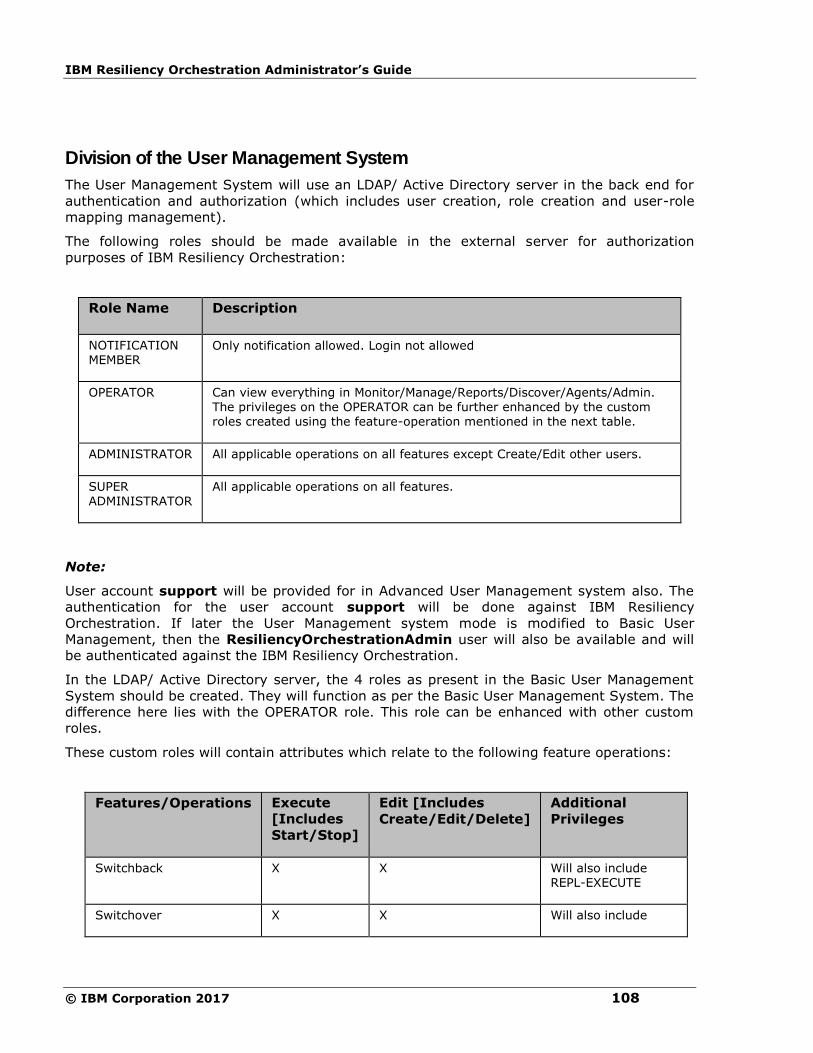
IBM Resiliency Orchestration Administrator’s Guide
© IBM Corporation 2017 108
Division of the User Management System
The User Management System will use an LDAP/ Active Directory server in the back end for
authentication and authorization (which includes user creation, role creation and user-role
mapping management).
The following roles should be made available in the external server for authorization
purposes of IBM Resiliency Orchestration:
Role Name Description
NOTIFICATION MEMBER
Only notification allowed. Login not allowed
OPERATOR Can view everything in Monitor/Manage/Reports/Discover/Agents/Admin. The privileges on the OPERATOR can be further enhanced by the custom roles created using the feature-operation mentioned in the next table.
ADMINISTRATOR All applicable operations on all features except Create/Edit other users.
SUPER ADMINISTRATOR
All applicable operations on all features.
Note:
User account support will be provided for in Advanced User Management system also. The
authentication for the user account support will be done against IBM Resiliency
Orchestration. If later the User Management system mode is modified to Basic User
Management, then the ResiliencyOrchestrationAdmin user will also be available and will
be authenticated against the IBM Resiliency Orchestration.
In the LDAP/ Active Directory server, the 4 roles as present in the Basic User Management
System should be created. They will function as per the Basic User Management System. The
difference here lies with the OPERATOR role. This role can be enhanced with other custom
roles.
These custom roles will contain attributes which relate to the following feature operations:
Features/Operations Execute
[Includes
Start/Stop]
Edit [Includes
Create/Edit/Delete]
Additional
Privileges
Switchback X X Will also include REPL-EXECUTE
Switchover X X Will also include
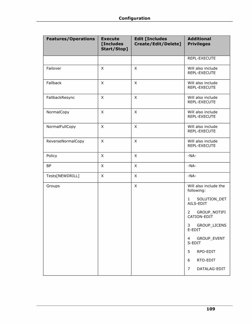
Configuration
109
Features/Operations Execute
[Includes
Start/Stop]
Edit [Includes
Create/Edit/Delete]
Additional
Privileges
REPL-EXECUTE
Failover X X Will also include REPL-EXECUTE
Fallback X X Will also include REPL-EXECUTE
FallbackResync X X Will also include REPL-EXECUTE
NormalCopy X X Will also include REPL-EXECUTE
NormalFullCopy X X Will also include REPL-EXECUTE
ReverseNormalCopy X X Will also include REPL-EXECUTE
Policy X X -NA-
BP X X -NA-
Tests[NEWDRILL] X X -NA-
Groups X Will also include the following:
1 SOLUTION_DETAILS-EDIT
2 GROUP_NOTIFICATION-EDIT
3 GROUP_LICENS
E-EDIT
4 GROUP_EVENT
S-EDIT
5 RPO-EDIT
6 RTO-EDIT
7 DATALAG-EDIT

IBM Resiliency Orchestration Administrator’s Guide
© IBM Corporation 2017 110
The custom roles will have a set of attributes which correspond to a combination of the
feature-operation mentioned in the table above. Assigning these attributes a value of
TRUE/FALSE will create a customized role. There will be no change in the GUI for supporting
role creation/customization and user management.
Note:
A user can also be assigned a custom role directly without being assigned an OPERATOR role.
By default the user will be assigned OPERATOR privileges internally and will be allowed to log
in and do operations pertaining to the custom role assigned.
For the User Management System, IBM Resiliency Orchestration will not ship with an
LDAP/ AD server. The server will have to configured/ provided by the customer at the site.
Testing of this module in Development and SQA environments will be done using OpenLDAP
[or 389 Directory Server in Fedora] on Linux and Active Directory on Windows.
On installation of IBM Resiliency Orchestration, a choice will be provided in the installer on
whether the Basic or Advanced User Management System has to be used.
The support user provided will function as in the previous releases.
Note:
▪ The ResiliencyOrchestrationAdmin user need not be created on the external
server in User Management mode. The product should function even without the
ResiliencyOrchestrationAdmin user account being created on the external server.
▪ Any of the internal processes (like executing policy workflows, scheduled workflows,
replication workflows etc) which are using the ResiliencyOrchestrationAdmin user
by default will be modified to take system as the user. So, in the audit log/ reports
the user who triggered the workflow will be shown as system [if audit log is
applicable] which gives a better understanding to the user since this will also avoid
the confusion of whether the workflow was triggered by somebody logging in as
ResiliencyOrchestrationAdmin or automatically started by the system.
▪ For any user that is created in the external server, a record is maintained for that
user for it's preferences with respect to the IBM Resiliency Orchestration. If the user
name is modified, the modified user name will be treated as a new user and the
record for the old user name will not be accessed on login. If the user is deleted in the
external system, the record for the deleted user in IBM Resiliency Orchestration will
still remain as there is no way to indicate back to the Resiliency Orchestration server
that the user is deleted.
Features and Relevant Operations To Be Handled
Features/
Operations
Create Read Update/
Edit
Delete Execut
e
Termi
nate
Advanced_Reports X X
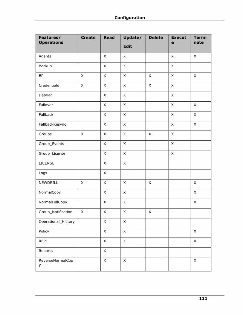
Configuration
111
Features/
Operations
Create Read Update/
Edit
Delete Execut
e
Termi
nate
Agents X X X X
Backup X X X
BP X X X X X X
Credentials X X X X X
Datalag X X X
Failover X X X X
Fallback X X X X
FallbackResync X X X X
Groups X X X X X
Group_Events X X X
Group_License X X X
LICENSE X X
Logs X
NEWDRILL X X X X X
NormalCopy X X X
NormalFullCopy X X X
Group_Notification X X X X
Operational_History X X
Policy X X X
REPL X X X
Reports X
ReverseNormalCopy
X X X
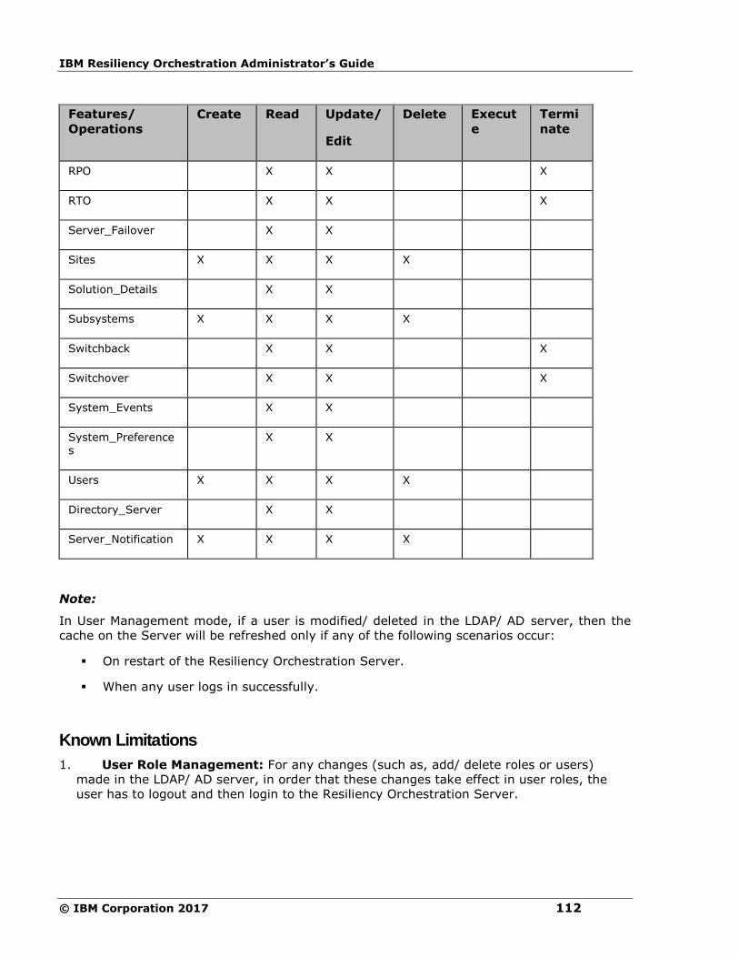
IBM Resiliency Orchestration Administrator’s Guide
© IBM Corporation 2017 112
Features/
Operations
Create Read Update/
Edit
Delete Execut
e
Termi
nate
RPO X X X
RTO X X X
Server_Failover X X
Sites X X X X
Solution_Details X X
Subsystems X X X X
Switchback X X X
Switchover X X X
System_Events X X
System_Preferences
X X
Users X X X X
Directory_Server X X
Server_Notification X X X X
Note:
In User Management mode, if a user is modified/ deleted in the LDAP/ AD server, then the
cache on the Server will be refreshed only if any of the following scenarios occur:
▪ On restart of the Resiliency Orchestration Server.
▪ When any user logs in successfully.
Known Limitations
1. User Role Management: For any changes (such as, add/ delete roles or users)
made in the LDAP/ AD server, in order that these changes take effect in user roles, the
user has to logout and then login to the Resiliency Orchestration Server.
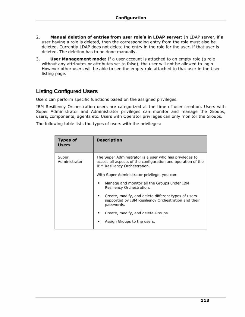
Configuration
113
2. Manual deletion of entries from user role’s in LDAP server: In LDAP server, if a
user having a role is deleted, then the corresponding entry from the role must also be
deleted. Currently LDAP does not delete the entry in the role for the user, if that user is
deleted. The deletion has to be done manually.
3. User Management mode: If a user account is attached to an empty role (a role
without any attributes or attributes set to false), the user will not be allowed to login.
However other users will be able to see the empty role attached to that user in the User
listing page.
Listing Configured Users
Users can perform specific functions based on the assigned privileges.
IBM Resiliency Orchestration users are categorized at the time of user creation. Users with
Super Administrator and Administrator privileges can monitor and manage the Groups,
users, components, agents etc. Users with Operator privileges can only monitor the Groups.
The following table lists the types of users with the privileges:
Types of
Users
Description
Super Administrator
The Super Administrator is a user who has privileges to access all aspects of the configuration and operation of the IBM Resiliency Orchestration.
With Super Administrator privilege, you can:
▪ Manage and monitor all the Groups under IBM Resiliency Orchestration.
▪ Create, modify, and delete different types of users supported by IBM Resiliency Orchestration and their passwords.
▪ Create, modify, and delete Groups.
▪ Assign Groups to the users.
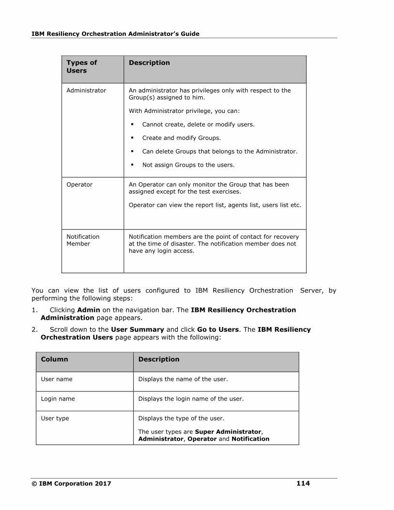
IBM Resiliency Orchestration Administrator’s Guide
© IBM Corporation 2017 114
Types of
Users
Description
Administrator An administrator has privileges only with respect to the Group(s) assigned to him.
With Administrator privilege, you can:
▪ Cannot create, delete or modify users.
▪ Create and modify Groups.
▪ Can delete Groups that belongs to the Administrator.
▪ Not assign Groups to the users.
Operator
An Operator can only monitor the Group that has been assigned except for the test exercises.
Operator can view the report list, agents list, users list etc.
Notification Member
Notification members are the point of contact for recovery at the time of disaster. The notification member does not have any login access.
You can view the list of users configured to IBM Resiliency Orchestration Server, by
performing the following steps:
1. Clicking Admin on the navigation bar. The IBM Resiliency Orchestration
Administration page appears.
2. Scroll down to the User Summary and click Go to Users. The IBM Resiliency
Orchestration Users page appears with the following:
Column Description
User name Displays the name of the user.
Login name Displays the login name of the user.
User type Displays the type of the user.
The user types are Super Administrator,
Administrator, Operator and Notification
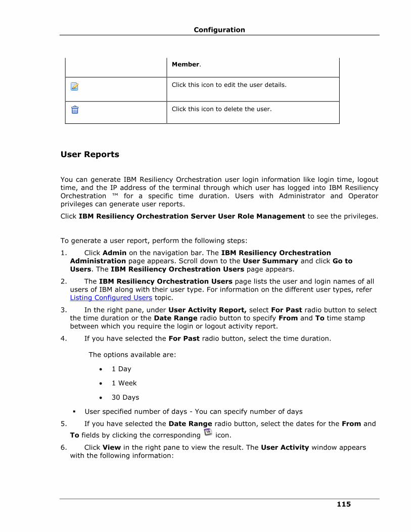
Configuration
115
Member.
Click this icon to edit the user details.
Click this icon to delete the user.
User Reports
You can generate IBM Resiliency Orchestration user login information like login time, logout
time, and the IP address of the terminal through which user has logged into IBM Resiliency
Orchestration ™ for a specific time duration. Users with Administrator and Operator
privileges can generate user reports.
Click IBM Resiliency Orchestration Server User Role Management to see the privileges.
To generate a user report, perform the following steps:
1. Click Admin on the navigation bar. The IBM Resiliency Orchestration
Administration page appears. Scroll down to the User Summary and click Go to
Users. The IBM Resiliency Orchestration Users page appears.
2. The IBM Resiliency Orchestration Users page lists the user and login names of all
users of IBM along with their user type. For information on the different user types, refer
Listing Configured Users topic.
3. In the right pane, under User Activity Report, select For Past radio button to select
the time duration or the Date Range radio button to specify From and To time stamp
between which you require the login or logout activity report.
4. If you have selected the For Past radio button, select the time duration.
The options available are:
• 1 Day
• 1 Week
• 30 Days
▪ User specified number of days - You can specify number of days
5. If you have selected the Date Range radio button, select the dates for the From and
To fields by clicking the corresponding icon.
6. Click View in the right pane to view the result. The User Activity window appears
with the following information:
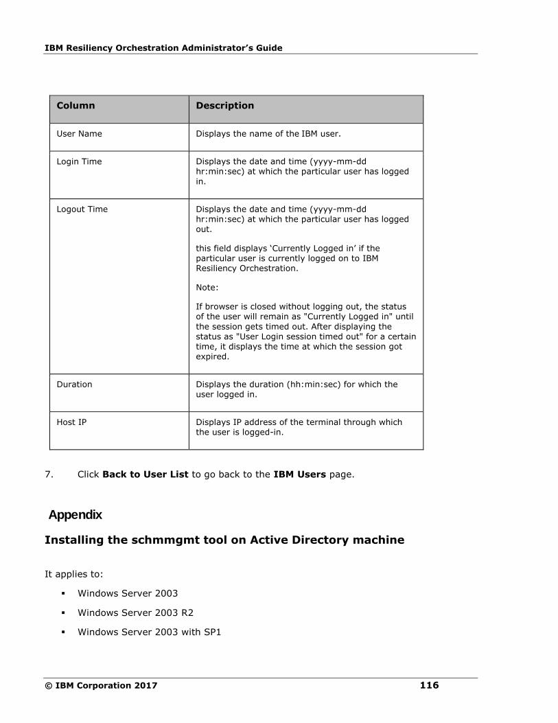
IBM Resiliency Orchestration Administrator’s Guide
© IBM Corporation 2017 116
Column Description
User Name Displays the name of the IBM user.
Login Time Displays the date and time (yyyy-mm-dd hr:min:sec) at which the particular user has logged
in.
Logout Time Displays the date and time (yyyy-mm-dd hr:min:sec) at which the particular user has logged
out.
this field displays ‘Currently Logged in’ if the particular user is currently logged on to IBM Resiliency Orchestration.
Note:
If browser is closed without logging out, the status of the user will remain as "Currently Logged in" until
the session gets timed out. After displaying the status as "User Login session timed out" for a certain time, it displays the time at which the session got expired.
Duration Displays the duration (hh:min:sec) for which the user logged in.
Host IP Displays IP address of the terminal through which the user is logged-in.
7. Click Back to User List to go back to the IBM Users page.
Appendix
Installing the schmmgmt tool on Active Directory machine
It applies to:
▪ Windows Server 2003
▪ Windows Server 2003 R2
▪ Windows Server 2003 with SP1
Configuration
117
▪ Windows Server 2003 with SP2
The steps followed to install the Active Directory Schema snap-in are:
1. Open Command Prompt.
2. Type regsvr32 schmmgmt.dll
This command will register Schmmgmt.dll on your computer. For more information on
using regsvr32, see Related Documents.
3. Click Start -> Run, type mmc /a, and click OK.
4. On the File menu, click Add/Remove Snap-in, and then click Add.
5. Under Available Standalone Snap-ins, double-click Active Directory Schema. Click
Close and click OK.
6. To save this console, on the File menu, click Save.
7. In Save in, point to the systemroot\system32 directory.
8. In File name, type schmmgmt.msc, and then click Save.
9. To create a shortcut on your Start menu:
▪ Right-click Start and click Open All Users. Double-click the programs folder and then
double-click the Administrative Tools folder.
▪ On the File menu, point to New, and then click Shortcut.
▪ In the Create Shortcut Wizard, in Type the location of the item, type schmmgmt.msc,
and then click Next.
▪ On the Select a Title for the program page, in Type a name for this shortcut, type
Active Directory Schema, and then click Finish.
Caution:
▪ Modifying the schema is an advanced operation best performed by experienced
programmers and system administrators. For detailed information about modifying
the schema, see the Active Directory programmer's Guide at the Microsoft Web site.
Note:
▪ To perform this procedure, you must be a member of the Domain Admins group or
the Enterprise Admins group in Active Directory, or you must have been delegated the
appropriate authority. As a security best practice, consider using Run as to perform
this procedure. For more information, see Default local groups, Default groups, and
Using Run as.
▪ You can also run the Active Directory Schema snap-in from a computer running
Windows XP Professional. Simply install the Windows Server 2003 Administration
Tools Pack on the computer, and then complete step 9 above.
▪ The Windows Server 2003 Administration Tools Pack cannot be installed on computers
running Windows 2000 Professional or Windows 2000 Server.
IBM Resiliency Orchestration Administrator’s Guide
© IBM Corporation 2017 118
Installing the ADSI Edit tool on Active Directory machine
It applies to:
▪ Windows SBS 2008
▪ Windows Server 2003
▪ Windows Server 2003 R2
▪ Windows Server 2003 with SP1
▪ Windows Server 2003 with SP2
▪ Windows Server 2008
▪ Windows Server 2008 R2
Active Directory® Service Interfaces Editor (ADSI Edit) is a Lightweight Directory Access
Protocol (LDAP) editor that you can use to manage objects and attributes in Active Directory.
ADSI Edit (adsiedit.msc) provides a view of every object and attribute in an Active Directory
forest. You can use ADSI Edit to query, view, and edit attributes that are not exposed
through other Active Directory Microsoft Management Console (MMC) snap-ins: Active
Directory Users and Computers, Active Directory Sites and Services, Active Directory
Domains and Trusts, and Active Directory Schema.
This topic includes the following sections:
▪ Installing ADSI Edit
▪ Using ADSI Edit
Installing ADSI Edit
To install ADSI Edit on computers running Windows Server® 2003 or Windows® XP
operating systems, install Windows Server 2003 Support Tools from the Windows Server
2003 product CD or from the Microsoft Download Center
(http://go.microsoft.com/fwlink/?LinkId=100114). For more information about how to install
Windows Support Tools from the product CD, see Install Windows Support Tools
(http://go.microsoft.com/fwlink/?LinkId=62270).
On servers running Windows Server 2008 or Windows Server 2008 R2, ADSI Edit is installed
when you install the Active Directory Domain Services (AD DS) role to make a server a
domain controller. You can also install Windows Server 2008 Remote Server Administration
Tools (RSAT) on domain member servers or stand-alone servers. For specific instructions,
see Installing or Removing the Remote Server Administration Tools Pack
(http://go.microsoft.com/fwlink/?LinkId=143345).
To install ADSI Edit on computers running Windows Vista® with Service Pack 1 (SP1) or
Windows 7, you must install RSAT. For more information and to download RSAT, see article
941314 in the Microsoft Knowledge Base (http://go.microsoft.com/fwlink/?LinkID=116179).
Configuration
119
Note:
▪ Adsiedit.msc will not run unless the Adsiedit.dll file is registered. This happens
automatically if the support tools are installed. However, if the support tool files are
copied instead of installed, you must run the regsvr32 command to register
Adsiedit.dll before you run the Adsiedit.msc snap-in. To register adsiedit.dll, type
the following command (you must navigate to the directory containing the
adsiedit.dll file): regsvr32 adsiedit.dll
▪ You can run ADSI Edit from a client computer or server. The computer does not have
to be a member of a domain. However, to see domain objects using Adsiedit.msc,
you must have the rights to view the Active Directory domain that you connect to. By
default, members of the Domain Users group have these rights. To modify objects
using ADSIEdit, you must have at least the Edit permission on the Active Directory
objects that you want to change. By default, members of the Domain Admins group
have this permission.
Using ADSI Edit
ADSI Edit (Adsiedit.msc) is an MMC snap-in. You can add the snap-in to any .msc file
through the Add/Remove Snap-in menu option in MMC, or just open the Adsiedit.msc file
from Windows Explorer. The following figure illustrates the ADSI Edit interface. In the
console tree on the left, you can see the major partitions Domain, Configuration, and
Schema. The figure shows the Builtin container of the Contoso.com domain selected. In the
details pane on the right, you can see the Builtin groups of Active Directory.
Note:
▪ Adsiedit.msc automatically attempts to load the current domain to which the user is
logged on. If the computer is installed in a workgroup or otherwise not logged on to a
domain, the message "The specified domain does not exist" displays repeatedly. To
resolve this issue, you may want to open an MMC, add the ADSI Edit snap-in, make
connections as appropriate, and then save the console file.
Notifications
Configuring Notifications
Notifications lists the users categorized under various notification names. You can configure
notifications to be sent to a selected set of users on occurrence of an event. These users can
only receive the notifications, but, cannot login into IBM Resiliency Orchestration.
The notifications are sent to the users through three modes of communications. They are:
▪ Email Notifications
▪ SMS Notifications
▪ SNMP Notifications
To view the list of members included in the notification list, perform the following steps:

IBM Resiliency Orchestration Administrator’s Guide
© IBM Corporation 2017 120
1. Click Admin on the navigation bar. The IBM Resiliency Orchestration
Administration page appears.
2. Scroll down to the Notification Summary and click Go to Notification. The
Notifications page appears.
Note: This page provides information on the following:
▪ E-mail Server details: Details of E-mail server configuration for sending and
receiving E-mails.
▪ Notification list: Provides information on configured list and its members with
options to edit or delete respective notification list.
▪ SNMP Trap Forwarder list: Provides information on configured SNMP Trap
Forwarder list with an option to delete respective SNMP Trap Forwarder list.
Email Notification
Each event is associated with a member or group of members. The notification regarding the
event is automatically sent to the email address of the user. Email notification is set up
through email server configuration.
When a BCO is initiated on an AG, notifications are sent to users in the notification list of the
AG. Following is a sample notification sent to the users configured to an AG and it’s
associated RG's.
Subject:
IBM Resiliency Orchestration: testAG1: Failover started at 2005-05-10 21:10:49.74
Notification:
Notification List: Test_NL1,
Group Details:
…Name: testAG1
Description: this is testAG1
Type: APPLICATION GROUP
Current Status: MANAGED, INACTIVE
Operational Details:
Continuity Operation: Failover
Status: Failover started
Configuration
121
Start Time: 2005-05-10 21:10:49.74
End Time: -
Actions to be performed by User: None
SMS Notification
SMS notification process is similar to the E-mail notification except for the notification
method. Here, you will be notified through SMS regarding an event. The SMS is sent to your
cell phone.
The information regarding the failure or success of Application Events, Infrastructure events
and Replication events is escalated to the respective users through Notifications.
SNMP Notification
SNMP notification provides the ability to receive notifications in the form of SNMP traps
through SNMP Trap forwarder.
Users with Administrator and Super Administrator privileges can use this type of notification.
Events of 'critical' and 'serious' types alone are notified through SNMP Trap Forwarder.
Note:
IBM Resiliency Orchestration supports SNMPV1 version for sending and receiving SNMP
traps. Ensure that third-party softwares installed on the client computers support SNMP
management.
The Management Information Base (MIB) file which is bundled along with IBM Resiliency
Orchestration software stores the details on how to read and interpret the Trap Forwarder
message. The notification list members can use this file for specific purposes like displaying
the events information in a particular format, etc. Contact IBM Resiliency Orchestration
support for loading the MIB file prior to using this feature.
Notification List
Configuring Notifications
This chapter describes how to setup and configure notifications.
In this section:
Adding Notification List
Modifying Notification List

IBM Resiliency Orchestration Administrator’s Guide
© IBM Corporation 2017 122
Deleting Notification List
Adding Notification List
A notification list can be created to group users based on notifications to be sent. A user with
administrator privilege only can create notification lists. While adding Notification List, the
existing users are categorized to escalate events in the form of notifications.
Refer IBM Resiliency Orchestration Server User Role Management to see the privileges.
To add a notification list perform following steps:
1. Click Admin on the navigation bar. The IBM Resiliency Orchestration
Administration page appears. Scroll down to the Notification Summary and click Go
to Notification. The Notifications page appears.
2. Click the Add Notification List link in the right pane.
3. Enter name for the notification list in the Notification List Name field.
4. Select the user name from the list. There are two boxes, one displaying all the users
of IBM Resiliency Orchestration (left side) and other (right side) displaying the selected
users for notification.
▪ Select a user of your choice from the available users list and click to add the user to
right side box. You can select more than one user by using the Ctrl key. The users
available in the right side box will be associated with the notification list being created.
The occurrences of event are escalated to the respective users belonging to notification
list.
▪ Deselect a user by selecting the user from the selected member list on the right side
list box (you can select more than one user by using the Ctrl key) and clicking . This
removes the user from being associated with the notification list.
Note:
The notification list name is mandatory and can accept alphanumeric characters,
spaces and underscores only. This field should start with an alphabet and accepts
only 30 characters. Select at least one user name from the list.
5. Click Save to save the changes and click OK in the pop-up message box to return to
the Notifications window.
OR
Click Cancel to quit the current window without saving changes.

Configuration
123
Modifying Notification List
Click IBM Resiliency Orchestration Server User Role Management to see the privileges.
To modify the properties of a notification list, perform the following steps:
1. Click Admin on the navigation bar. The IBM Resiliency Orchestration
Administration page appears. Scroll down to the Notification Summary and click Go
to Notification. The Notifications page appears.
2. Click icon corresponding to the notification list that you want to modify. The Edit
Notifications List section appears.
3. You can change the list of notification members. To do this:
▪ Select a user of your choice from the Users list and click >> to add the user to the right
side box. This associates the user with the notification list name.
OR
▪ Deselect users by highlighting a user from the selected member list on the right side
list box and clicking << button. This removes the user from being associated with the
notification list name
4. Click Save to save the changes and click OK in the pop-up message box to return to
the Notifications window.
OR
Click Cancel to quit the current window without saving changes.
Note:
The notification list name should have at least one user associated with it.
You can modify the Notification List in the Group Setup page also.

IBM Resiliency Orchestration Administrator’s Guide
© IBM Corporation 2017 124
Deleting Notification List
Refer IBM Resiliency Orchestration Server User Role Management to see the privileges.
To delete a notification list perform following steps:
1. Click Admin on the navigation bar. The IBM Resiliency Orchestration
Administration page appears. Scroll down to the Notification Summary and click Go
to Notification. The Notifications page appears.
2. Click corresponding to the notification list that you want to delete. A message box
is displayed confirming the deletion.
3. Click OK in the message box.
Configuring SNMP Trap Forwarder
Click IBM Resiliency Orchestration Server User Role Management to see the privileges.
To configure SNMP Trap Forwarder console to IBM Resiliency Orchestration server to receive
the notification in the form of a SNMP Trap, perform the following:
1. Click Admin on the navigation bar. The IBM Resiliency Orchestration
Administration page appears.
2. Scroll down to the Notification Summary and click Go to Notification. The
Notifications page appears.
3. Click the Add SNMP TRAP Forwarder link in the right pane. The SNMP Trap
Forwarder page appears.
Provide the necessary information in the following fields:
Field Description
SNMP Trap Name Enter a name for the SNMP Trap.
This field is mandatory.
SNMP Trap Destination IP
Enter the IP address of the trap destination.
This field is mandatory.

Configuration
125
Field Description
UDP Port Enter the UDP (User Datagram Protocol) port number of the trap destination.
The default is port 162.
This field is mandatory.
SNMP Version This is a non-editable field.
IBM Resiliency Orchestration supports SNMPV1 version for sending and receiving SNMP traps.
Community String
Enter the community string.
It is a password that allows access to a network device. It defines which category of people can access the SNMP information on the device.
The person responsible for the network device typically sets the community strings.
Enable SNMP Trap Select this check box to enable the SNMP Console to receive the notification.
Select Groups Select the groups for which you want to send the notification from the list box.
You can select more than one group by using the Ctrl key.
4. Click Save to save the changes and click OK in the pop-up message box to return to
the Notifications window.
OR
5. Click Cancel to quit the current window without saving changes.
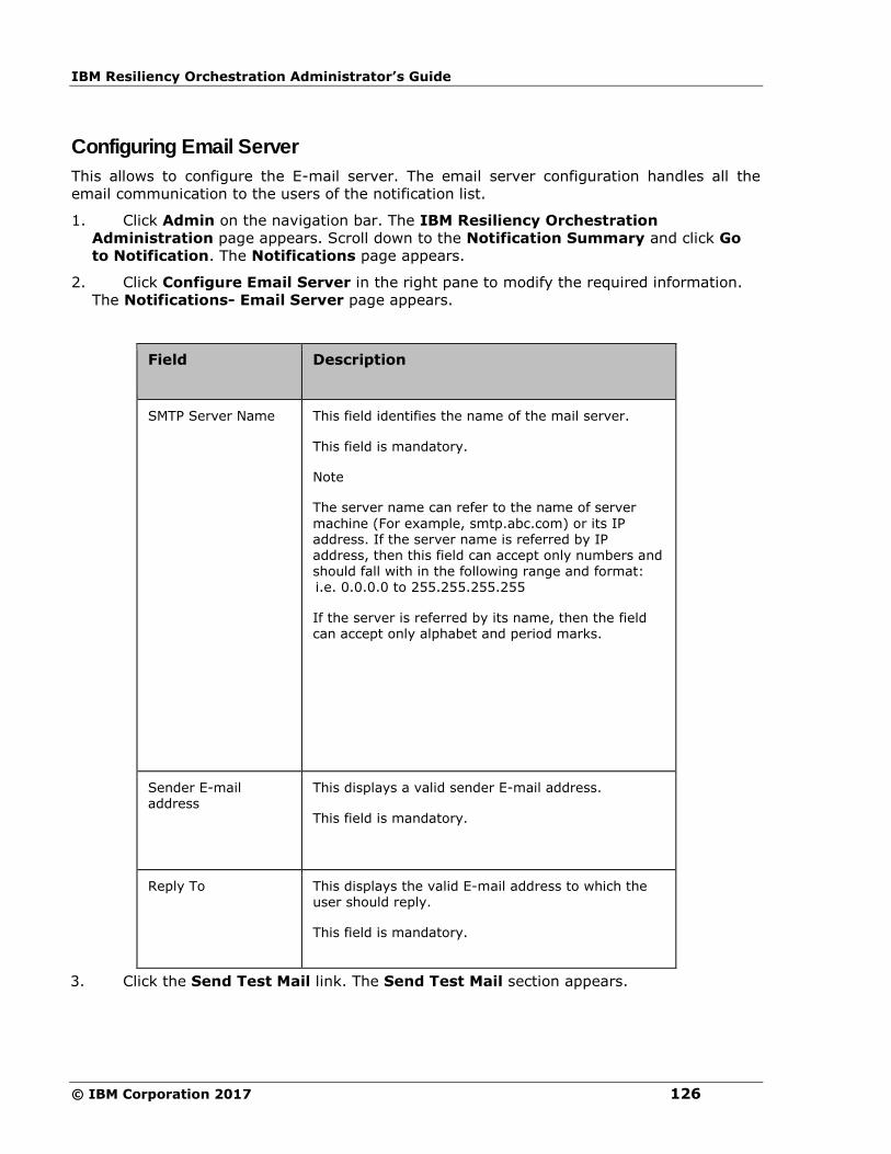
IBM Resiliency Orchestration Administrator’s Guide
© IBM Corporation 2017 126
Configuring Email Server
This allows to configure the E-mail server. The email server configuration handles all the
email communication to the users of the notification list.
1. Click Admin on the navigation bar. The IBM Resiliency Orchestration
Administration page appears. Scroll down to the Notification Summary and click Go
to Notification. The Notifications page appears.
2. Click Configure Email Server in the right pane to modify the required information.
The Notifications- Email Server page appears.
Field Description
SMTP Server Name This field identifies the name of the mail server.
This field is mandatory.
Note
The server name can refer to the name of server
machine (For example, smtp.abc.com) or its IP address. If the server name is referred by IP address, then this field can accept only numbers and should fall with in the following range and format: i.e. 0.0.0.0 to 255.255.255.255
If the server is referred by its name, then the field can accept only alphabet and period marks.
Sender E-mail address
This displays a valid sender E-mail address.
This field is mandatory.
Reply To
This displays the valid E-mail address to which the user should reply.
This field is mandatory.
3. Click the Send Test Mail link. The Send Test Mail section appears.
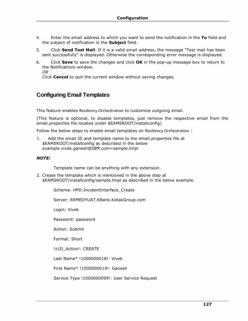
Configuration
127
4. Enter the email address to which you want to send the notification in the To field and
the subject of notification in the Subject field.
5. Click Send Test Mail. If it is a valid email address, the message "Test mail has been
sent successfully" is displayed. Otherwise the corresponding error message is displayed.
6. Click Save to save the changes and click OK in the pop-up message box to return to
the Notifications window.
OR
Click Cancel to quit the current window without saving changes.
Configuring Email Templates
This feature enables Resiliency Orchestration to customize outgoing email.
(This feature is optional, to disable templates, just remove the respective email from the
email.properties file located under $EAMSROOT/installconfig)
Follow the below steps to enable email templates on Resiliency Orchestration :
1. Add the email ID and template name to the email.properties file at
$EAMSROOT/installconfig as described in the below
[email protected]=sample.tmpl
NOTE:
Template name can be anything with any extension.
2. Create the template which is mentioned in the above step at
$EAMSROOT/installconfig/sample.tmpl as described in the below example.
Schema: HPD:IncidentInterface_Create
Server: REMEDYUAT.KBank.KotakGroup.com
Login: Vivek
Password: password
Action: Submit
Format: Short
!z1D_Action!: CREATE
Last Name* !1000000018!: Vivek
First Name* !1000000019!: Ganesh
Service Type !1000000099!: User Service Request

IBM Resiliency Orchestration Administrator’s Guide
© IBM Corporation 2017 128
Status ! 7!: New
Reported Source !1000000215!: Email
Service Categorization Tier 1 !1000000063!: Functionality
Product Categorization Tier 1 ! 200000003!: Applications
Product Categorization Tier 2 ! 200000004!: $occured on$
Impact* !1000000163!: 1-Extensive/Widespread
Urgency* !1000000162!: 1-Critical
Description !1000000000!: $description$
Details !1000000151!: $event$ - $event id$ - $time occurred$
NOTE:
The values specified within $ will be replaced with the actual values send by
Resiliency Orchestration . Text within $ should be in lower case (case sensitive), but
make sure the names are as it is from the original IBM Resiliency Orchestration
notification email.
3. Create Resiliency Orchestration user with the respective email used for templates and add to
the notification list. Make sure to have a separate notification list for these users and
attach the same to the group.
Business Process Integration
Some business processes that may or may not related to your DR environment need to co-
exist along with the processes monitored and managed by IBM Resiliency Orchestration.
Business Process Integration (BPI) allows you to incorporate such processes into IBM
Resiliency Orchestration workflow and therefore into DR environment.
Examples of such processes are daily back-ups of your database servers and the end of the
day operations that may impact BCOs.
Once configured, one or more such BPIs can run on Production or on the DR at the same
time. They can be configured to run only once or on periodic basis. These BPIs are associated
with the Functional Groups.

Configuration
129
BPIs are configured and incorporated into IBM Resiliency Orchestration using workflows
defined in XML files. These XML files are then imported to include a BPI. XML files are
validated before letting them integrated in IBM Resiliency Orchestration environment. Once
validated and imported, IBM Resiliency Orchestration system saves the timestamp of import,
name of the XML file, and the version. They can be exported for archiving or editing.
Exported workflow is also saved in XML format.
Listing Business Process Schedules
Click IBM Resiliency Orchestration Server User Role Management to see the privileges.
To list the schedules of all the business processes configured for a Recovery Group, perform
the steps given below:
1. Click DISCOVER > Groups on the navigation bar. The Groups page appears.
2. Click the Recovery Groups tab, the respective Group Listing page appears.
3. Click the required group from the GROUP NAME column. The Group Details Page
appears.
4. Click the Group Configuration tab.
5. Click the Business Processes tab to list the business processes of the Group.
This lists all the configured business processes, if any, for the Group with the following
details.
Field Description
Business Process Name Displays the name of the business process.
Business Process Description Displays the description for the business process.
Frequency Displays the frequency of business process schedule that is already configured.
Schedule Displays information about the schedule, if already configured. Otherwise the column displays as Not configured.
Status Displays the status of the business process.

IBM Resiliency Orchestration Administrator’s Guide
© IBM Corporation 2017 130
Field Description
The possible status are Enabled and N/A.
Adding Business Process
Refer IBM Resiliency Orchestration Server User Role Management to see the privileges.
You can add a business process to a Recovery Group or an Application Group.
To add a Business Process, follow the steps given below:
1. Click DISCOVER > Groups on the navigation bar. The Groups page appears.
2. Click Recovery Group or Application Group tab, the respective Group listing page
appears.
3. Click the required group from the GROUP NAME column for which you want to add
business process. The Group Details page appears.
4. Click the Group Configuration tab.
5. Click the Business Processes tab.
6. Under the Business Process Integration section, click the Add new Business
Process link. The Create Business Process dialog box appears.
Configure the following field elements:
Field Description
Group Name Displays the group name for which you want to add the business process.
Business Process Name Enter a unique name for the business process.
This field is mandatory.

Configuration
131
Field Description
Business Process Description Enter a description for the business process.
This field is mandatory.
7. Click Add.
or
Click Cancel to cancel the current operation.
Configuring Business Process
Click IBM Resiliency Orchestration Server User Role Management to see the privileges.
To configure the new business process:
1. Click DISCOVER > Groups on the navigation bar. The Groups page appears.
2. Click Recovery Group or Application Group tab, the respective Group Listing page
appears.
3. Click the required group from the GROUP NAME column for which you want to configure
the business process. The Group Details Page appears.
4. Click the Group Configuration tab.
5. Click the Business Processes tab.
6. Click corresponding to the business process of interest. The Workflow Details page
appears, where you can configure and schedule the business process.
Custom Event
Custom events are those events that are not already available in IBM Resiliency
Orchestration; but they are required in your DR related business processes. You can
configure to raise customized events in IBM Resiliency Orchestration. This is done using a
shell script that can be imported into IBM Resiliency Orchestration at command line. You
need to write this script to suit to your needs.
The script takes values such as event name, description, severity, and impact, policy window
name, policy workflow details, and Group name. This script sends configured events to the
IBM Resiliency Orchestration server. However, such scripts need to be validated before
importing or exporting for any possible errors.
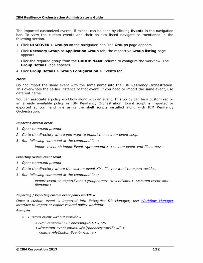
IBM Resiliency Orchestration Administrator’s Guide
© IBM Corporation 2017 132
The imported customized events, if raised, can be seen by clicking Events in the navigation
bar. To view the custom events and their policies listed navigate as mentioned in the
following section.
1. Click DISCOVER > Groups on the navigation bar. The Groups page appears.
2. Click Recovery Group or Application Group tab, the respective Group listing page
appears.
3. Click the required group from the GROUP NAME column to configure the workflow. The
Group Details Page appears.
4. Click Group Details > Group Configuration > Events tab.
Note:
Do not import the same event with the same name into the IBM Resiliency Orchestration.
This overwrites the earlier instance of that event. If you need to import the same event, use
different name.
You can associate a policy workflow along with an event. This policy can be a customized or
an already available policy in IBM Resiliency Orchestration. Event script is imported or
exported at command line using the shell scripts installed along with IBM Resiliency
Orchestration.
Importing custom event
1 Open command prompt.
2 Go to the directory where you want to import the custom event script.
3 Run following command at the command line:
import-event.sh importEvent <groupname> <custom event-xml-filename>
Exporting custom event script
1 Open command prompt.
2 Go to the directory where the custom event XML file you want to export resides.
3 Run following command at the command line:
export-event.sh exportEvent <groupname> <eventName> <custom event-xml-
filename>
Importing / Exporting custom event policy workflow
Once a custom event is imported into Enterprise DR Manager, use Workflow Manager
interface to import or export related policy workflow.
Examples
▪ Custom event without workflow
<?xml version="1.0" encoding="UTF-8"?>
<wf:custom-event xmlns:wf="/panaces/workflow/" >
<name>MyCustomEvent</name>
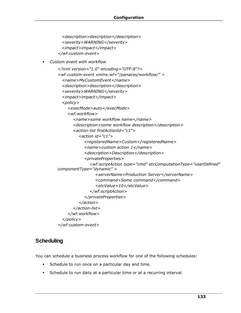
Configuration
133
<description>description</description>
<severity>WARNING</severity>
<impact>impact</impact>
</wf:custom-event>
▪ Custom event with workflow
<?xml version="1.0" encoding="UTF-8"?>
<wf:custom-event xmlns:wf="/panaces/workflow/" >
<name>MyCustomEvent</name>
<description>description</description>
<severity>WARNING</severity>
<impact>impact</impact>
<policy>
<execMode>auto</execMode>
<wf:workflow>
<name>some workflow name</name>
<description>some workflow description</description>
<action-list firstActionId="c1">
<action id="c1">
<registeredName>Custom</registeredName>
<name>custom action 1</name>
<description>Description</description>
<privateProperties>
<wf:scriptAction type="cmd" etcComputationType="userDefined"
componentType="dynamic" >
<serverName>Production Server</serverName>
<command>Some command</command>
<etcValue>10</etcValue>
</wf:scriptAction>
</privateProperties>
</action>
</action-list>
</wf:workflow>
</policy>
</wf:custom-event>
Scheduling
You can schedule a business process workflow for one of the following schedules:
▪ Schedule to run once on a particular day and time.
▪ Schedule to run daily at a particular time or at a recurring interval.
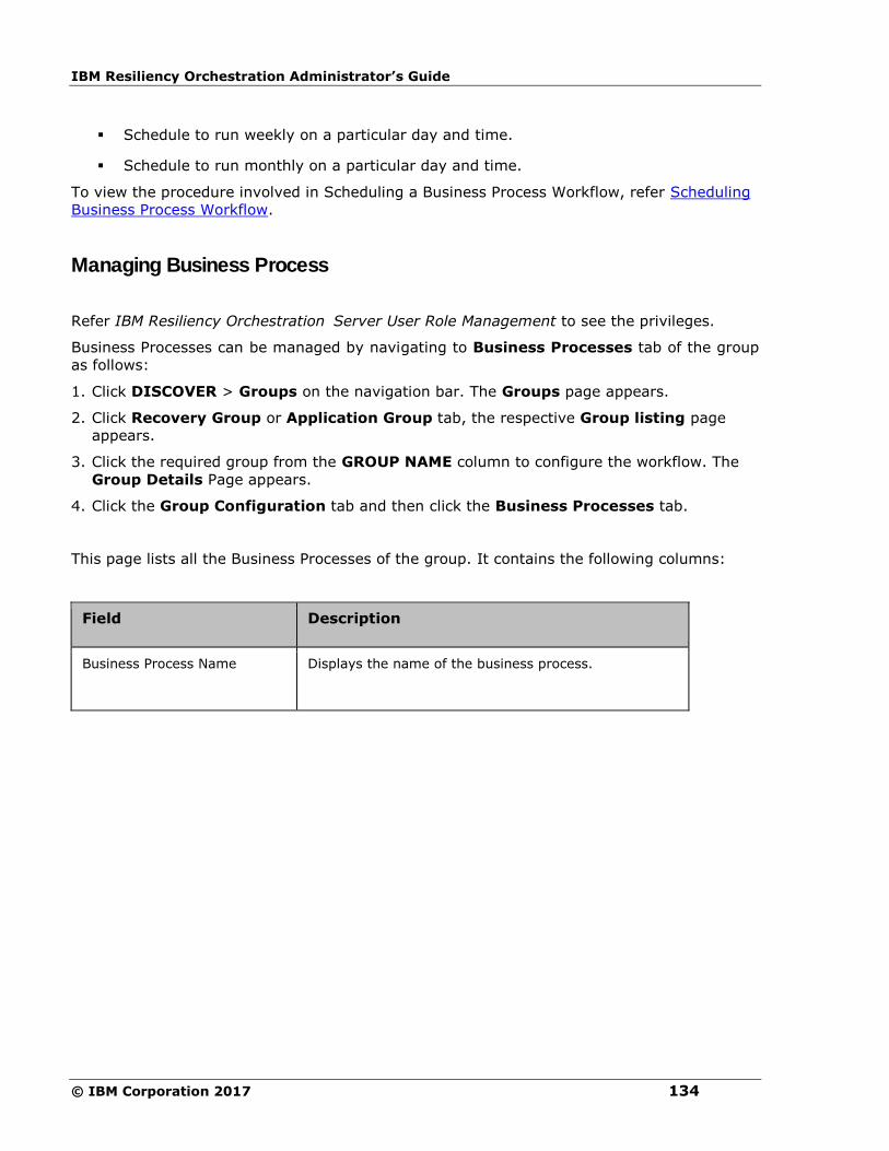
IBM Resiliency Orchestration Administrator’s Guide
© IBM Corporation 2017 134
▪ Schedule to run weekly on a particular day and time.
▪ Schedule to run monthly on a particular day and time.
To view the procedure involved in Scheduling a Business Process Workflow, refer Scheduling
Business Process Workflow.
Managing Business Process
Refer IBM Resiliency Orchestration Server User Role Management to see the privileges.
Business Processes can be managed by navigating to Business Processes tab of the group
as follows:
1. Click DISCOVER > Groups on the navigation bar. The Groups page appears.
2. Click Recovery Group or Application Group tab, the respective Group listing page
appears.
3. Click the required group from the GROUP NAME column to configure the workflow. The
Group Details Page appears.
4. Click the Group Configuration tab and then click the Business Processes tab.
This page lists all the Business Processes of the group. It contains the following columns:
Field Description
Business Process Name Displays the name of the business process.

Configuration
135
Field Description
Status Displays the current status of the business process. It can be one of the following:
▪ Never Executed -The status indicates that the Business Process is not executed.
▪ Executing - The status indicates that the
workflow is executing.
▪ Awaiting Input - The status indicates that the workflow requires user input to proceed.
▪ Success - The status indicates that the workflow is completed successfully.
▪ Failed - The status indicates that the workflow execution has failed.
▪ Aborted - The status indicates that the workflow has been aborted.
▪ Crashed - The status indicates that the IBM Resiliency Orchestration has shutdown during execution.
Last Execution Time Time when the business process was executed last time.
Action Actions can be one of the following:
▪ Start - To start the business process
▪ Stop - To stop the business process. This
option is available only when business process is in progress.
▪ Resume - To resume the business process. This option is available only when business process has crashed earlier.
Deleting Business Process
Click IBM Resiliency Orchestration Server User Role Management to see the privileges.
A business process can be deleted from the Group Details page of a Recovery Group.
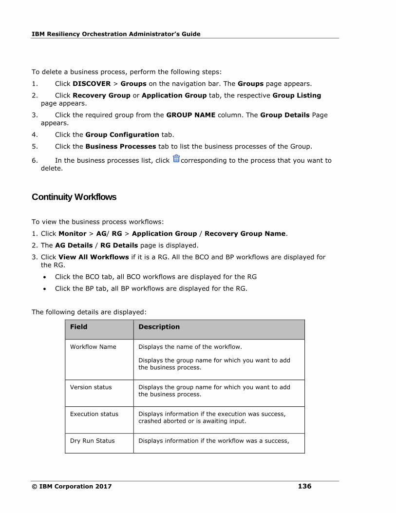
IBM Resiliency Orchestration Administrator’s Guide
© IBM Corporation 2017 136
To delete a business process, perform the following steps:
1. Click DISCOVER > Groups on the navigation bar. The Groups page appears.
2. Click Recovery Group or Application Group tab, the respective Group Listing
page appears.
3. Click the required group from the GROUP NAME column. The Group Details Page
appears.
4. Click the Group Configuration tab.
5. Click the Business Processes tab to list the business processes of the Group.
6. In the business processes list, click corresponding to the process that you want to
delete.
Continuity Workflows
To view the business process workflows:
1. Click Monitor > AG/ RG > Application Group / Recovery Group Name.
2. The AG Details / RG Details page is displayed.
3. Click View All Workflows if it is a RG. All the BCO and BP workflows are displayed for
the RG.
• Click the BCO tab, all BCO workflows are displayed for the RG
• Click the BP tab, all BP workflows are displayed for the RG.
The following details are displayed:
Field Description
Workflow Name Displays the name of the workflow.
Displays the group name for which you want to add the business process.
Version status Displays the group name for which you want to add the business process.
Execution status Displays information if the execution was success, crashed aborted or is awaiting input.
Dry Run Status Displays information if the workflow was a success,
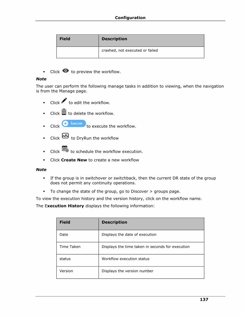
Configuration
137
Field Description
crashed, not executed or failed
▪ Click to preview the workflow.
Note
The user can perform the following manage tasks in addition to viewing, when the navigation
is from the Manage page.
▪ Click to edit the workflow.
▪ Click to delete the workflow.
▪ Click to execute the workflow.
▪ Click to DryRun the workflow
▪ Click to schedule the workflow execution.
▪ Click Create New to create a new workflow
Note
▪ If the group is in switchover or switchback, then the current DR state of the group
does not permit any continuity operations.
▪ To change the state of the group, go to Discover > groups page.
To view the execution history and the version history, click on the workflow name.
The Execution History displays the following information:
Field Description
Date Displays the date of execution
Time Taken Displays the time taken in seconds for execution
status Workflow execution status
Version Displays the version number

IBM Resiliency Orchestration Administrator’s Guide
© IBM Corporation 2017 138
The Version History displays the following information:
Field Description
Version Displays the version number
Created On Displays the workflow created time
Created By Displays the User name
Workflow Manager
Workflow is a sequence of steps/tasks performed to complete a business process. The
business process could be a Business Continuity Operation or DR Drill or EOD operation.
Actions and workflows are a set of procedures that are configured to act against an event in
the DR environment. You cannot add or delete an Action from a Workflow when it is being
executed.
Workflow manager enables you to design the workflow logic, execute and view the execution
status.
Configuring the workflow involves:
▪ Design the workflow logic.
- Insert/delete actions to be performed
- Provide/alter inputs to the actions
▪ Flow control
- Conditions to quit/abort workflow
- Handle failure conditions
- Recursion (execute an action periodically)
▪ Scheduling the workflow
Executing the workflow involves:
▪ Execute (start/stop) workflow
▪ Schedule workflow
Execution Status:
▪ Show execution status
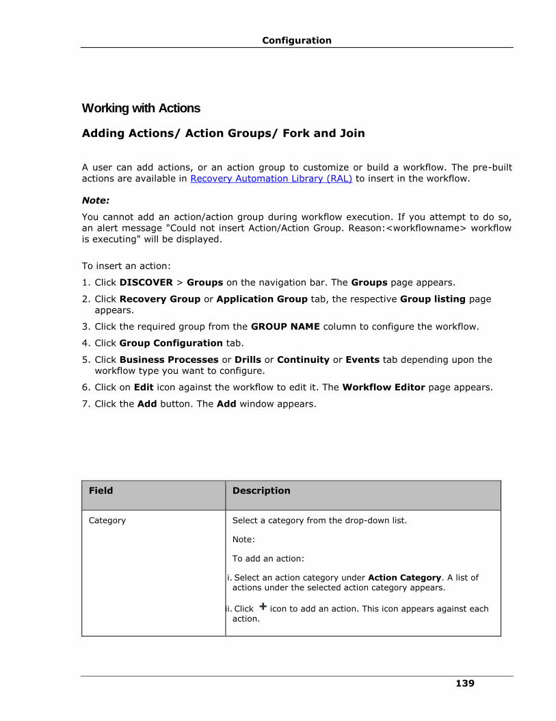
Configuration
139
Working with Actions
Adding Actions/ Action Groups/ Fork and Join
A user can add actions, or an action group to customize or build a workflow. The pre-built
actions are available in Recovery Automation Library (RAL) to insert in the workflow.
Note:
You cannot add an action/action group during workflow execution. If you attempt to do so,
an alert message "Could not insert Action/Action Group. Reason:<workflowname> workflow
is executing" will be displayed.
To insert an action:
1. Click DISCOVER > Groups on the navigation bar. The Groups page appears.
2. Click Recovery Group or Application Group tab, the respective Group listing page
appears.
3. Click the required group from the GROUP NAME column to configure the workflow.
4. Click Group Configuration tab.
5. Click Business Processes or Drills or Continuity or Events tab depending upon the
workflow type you want to configure.
6. Click on Edit icon against the workflow to edit it. The Workflow Editor page appears.
7. Click the Add button. The Add window appears.
Field Description
Category Select a category from the drop-down list.
Note:
To add an action:
i. Select an action category under Action Category. A list of actions under the selected action category appears.
ii. Click icon to add an action. This icon appears against each action.

IBM Resiliency Orchestration Administrator’s Guide
© IBM Corporation 2017 140
Field Description
To add an Action Group:
i. Click on to add an action group. It will add the default action group.
To add Workflows:
i. Select from the Select Signature Solution from the drop-down list.
ii. Click Import Workflow.
To add fork and join:
i. Click on icon to add a fork node. It is used to execute actions in parallel.
ii. Click on icon to add a join node. It is used to wait for executed forked actions.
Inserted Action Destinations
Success Path Drag the green bubble to the next destination action.
Failure Path Drag the red bubble to the next destination action.
8. Click Save now to add an action.
Configuring Actions
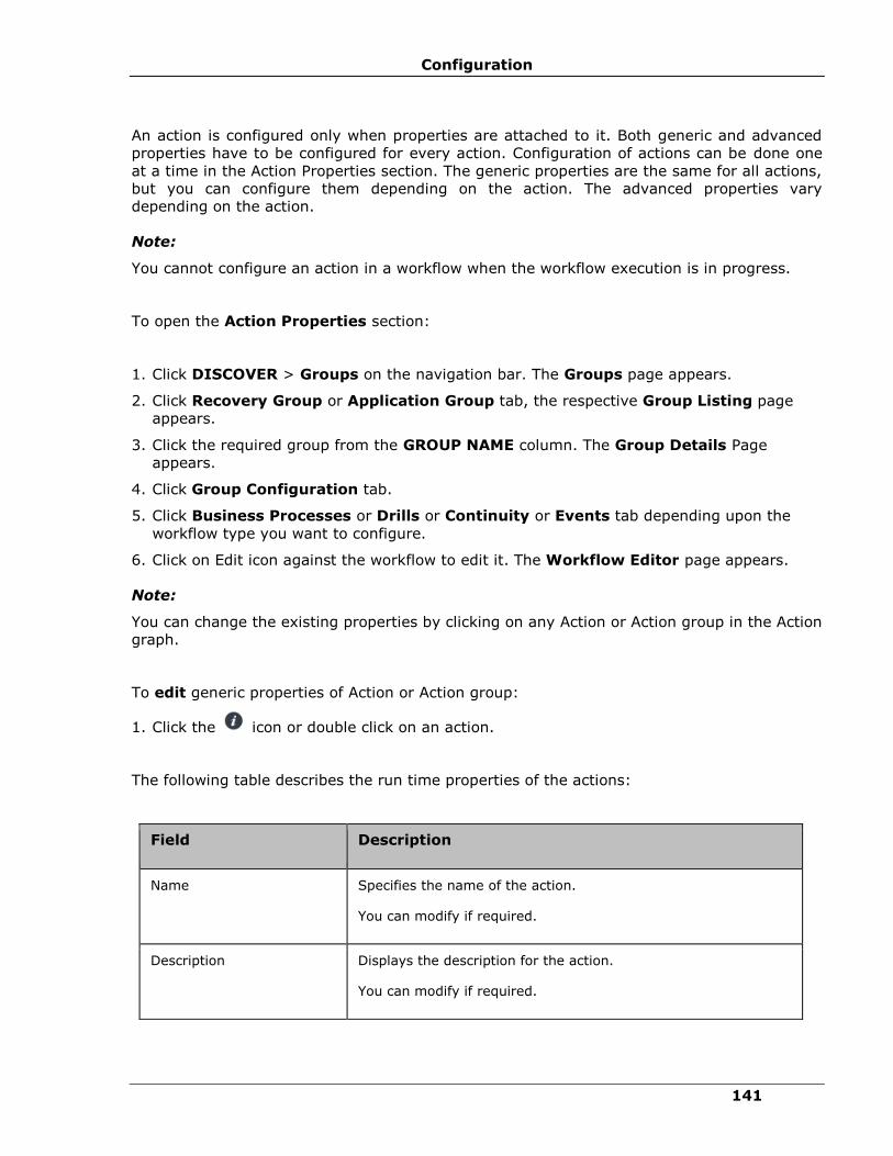
Configuration
141
An action is configured only when properties are attached to it. Both generic and advanced
properties have to be configured for every action. Configuration of actions can be done one
at a time in the Action Properties section. The generic properties are the same for all actions,
but you can configure them depending on the action. The advanced properties vary
depending on the action.
Note:
You cannot configure an action in a workflow when the workflow execution is in progress.
To open the Action Properties section:
1. Click DISCOVER > Groups on the navigation bar. The Groups page appears.
2. Click Recovery Group or Application Group tab, the respective Group Listing page
appears.
3. Click the required group from the GROUP NAME column. The Group Details Page
appears.
4. Click Group Configuration tab.
5. Click Business Processes or Drills or Continuity or Events tab depending upon the
workflow type you want to configure.
6. Click on Edit icon against the workflow to edit it. The Workflow Editor page appears.
Note:
You can change the existing properties by clicking on any Action or Action group in the Action
graph.
To edit generic properties of Action or Action group:
1. Click the icon or double click on an action.
The following table describes the run time properties of the actions:
Field Description
Name Specifies the name of the action.
You can modify if required.
Description Displays the description for the action.
You can modify if required.

IBM Resiliency Orchestration Administrator’s Guide
© IBM Corporation 2017 142
Field Description
Execution Mode This property indicates your intervention preference in action execution. It is either Manual or Auto. Default setting for each action is Auto.
▪ Manual specifies that there is some user intervention to execute the action. To enable the action to raise an Input Required event, set it to Manual execution mode.
▪ Auto specifies that no user intervention is required to execute the action.
In case the Retry on Failure checkbox is selected and the
Execution Mode is set as Manual, then action is executed without manual intervention.
Inform Upon This property indicates whether to notify after the Action execution completes. Notification is done based on the value of this property. The available options are:
▪ No Inform
▪ Inform on Success
▪ Inform on Failure
▪ Inform All
If the property is set to Inform on Success, notification is done
only after successful execution of the action.
If Inform Upon is set to Inform All or Inform on Failure and
Retry on Failure is also configured:
▪ Notification is done only once after the execution of the action
▪ In case, the action fails during first execution instance, then Retry on Failure will try to execute the action
again without notification.
▪ If the action fails on all attempts, the user is notified and has the control to continue/quit/retry etc.
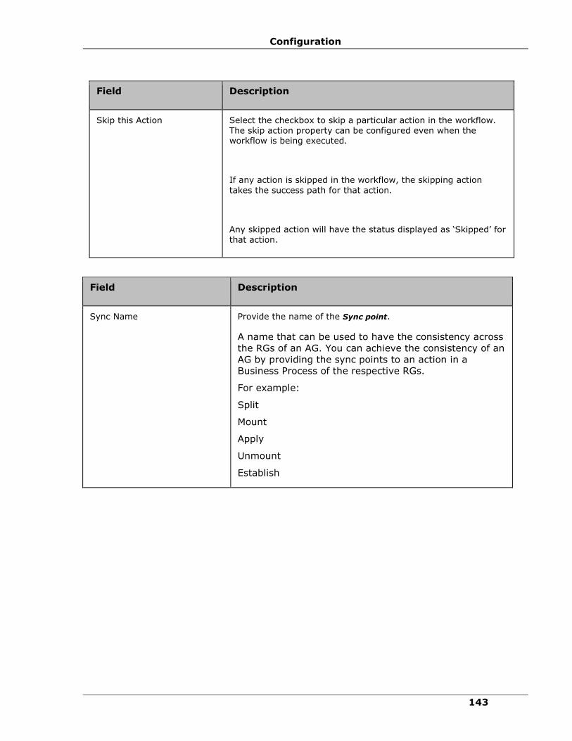
Configuration
143
Field Description
Skip this Action Select the checkbox to skip a particular action in the workflow. The skip action property can be configured even when the workflow is being executed.
If any action is skipped in the workflow, the skipping action
takes the success path for that action.
Any skipped action will have the status displayed as ‘Skipped’ for
that action.
Field Description
Sync Name Provide the name of the Sync point.
A name that can be used to have the consistency across
the RGs of an AG. You can achieve the consistency of an
AG by providing the sync points to an action in a
Business Process of the respective RGs.
For example:
Split
Mount
Apply
Unmount
Establish
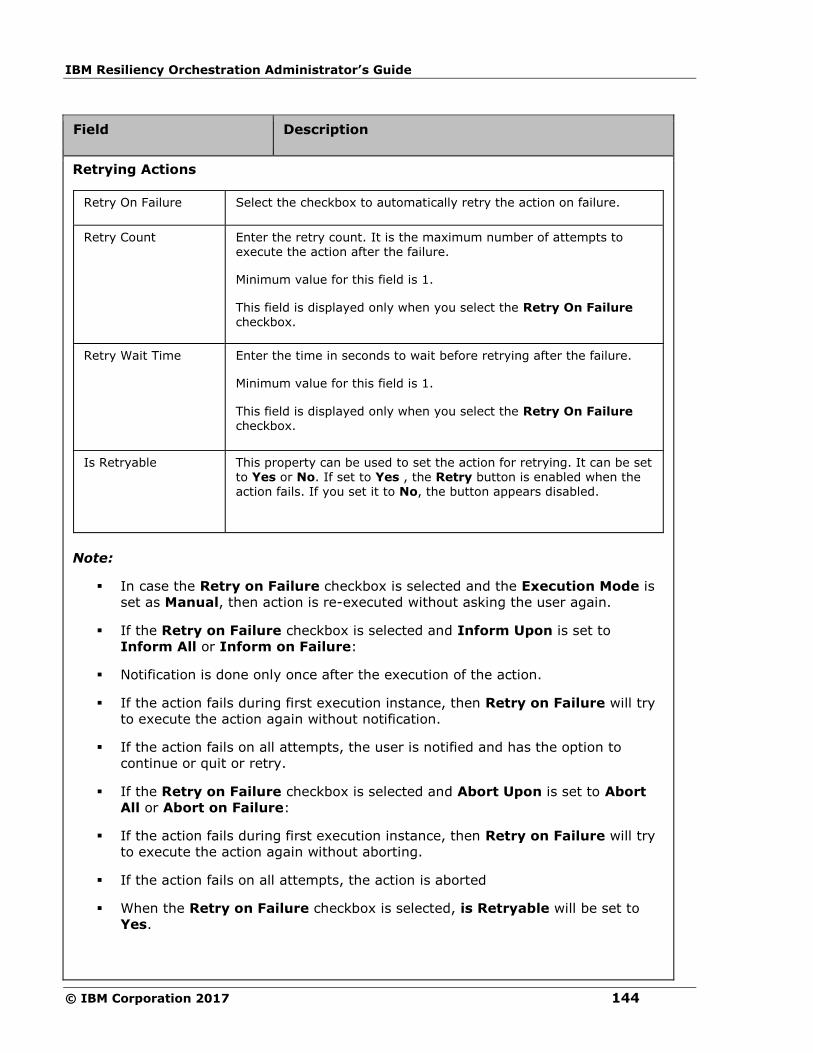
IBM Resiliency Orchestration Administrator’s Guide
© IBM Corporation 2017 144
Field Description
Retrying Actions
Retry On Failure Select the checkbox to automatically retry the action on failure.
Retry Count Enter the retry count. It is the maximum number of attempts to execute the action after the failure.
Minimum value for this field is 1.
This field is displayed only when you select the Retry On Failure checkbox.
Retry Wait Time Enter the time in seconds to wait before retrying after the failure.
Minimum value for this field is 1.
This field is displayed only when you select the Retry On Failure checkbox.
Is Retryable This property can be used to set the action for retrying. It can be set to Yes or No. If set to Yes , the Retry button is enabled when the action fails. If you set it to No, the button appears disabled.
Note:
▪ In case the Retry on Failure checkbox is selected and the Execution Mode is
set as Manual, then action is re-executed without asking the user again.
▪ If the Retry on Failure checkbox is selected and Inform Upon is set to
Inform All or Inform on Failure:
▪ Notification is done only once after the execution of the action.
▪ If the action fails during first execution instance, then Retry on Failure will try
to execute the action again without notification.
▪ If the action fails on all attempts, the user is notified and has the option to
continue or quit or retry.
▪ If the Retry on Failure checkbox is selected and Abort Upon is set to Abort
All or Abort on Failure:
▪ If the action fails during first execution instance, then Retry on Failure will try
to execute the action again without aborting.
▪ If the action fails on all attempts, the action is aborted
▪ When the Retry on Failure checkbox is selected, is Retryable will be set to
Yes.
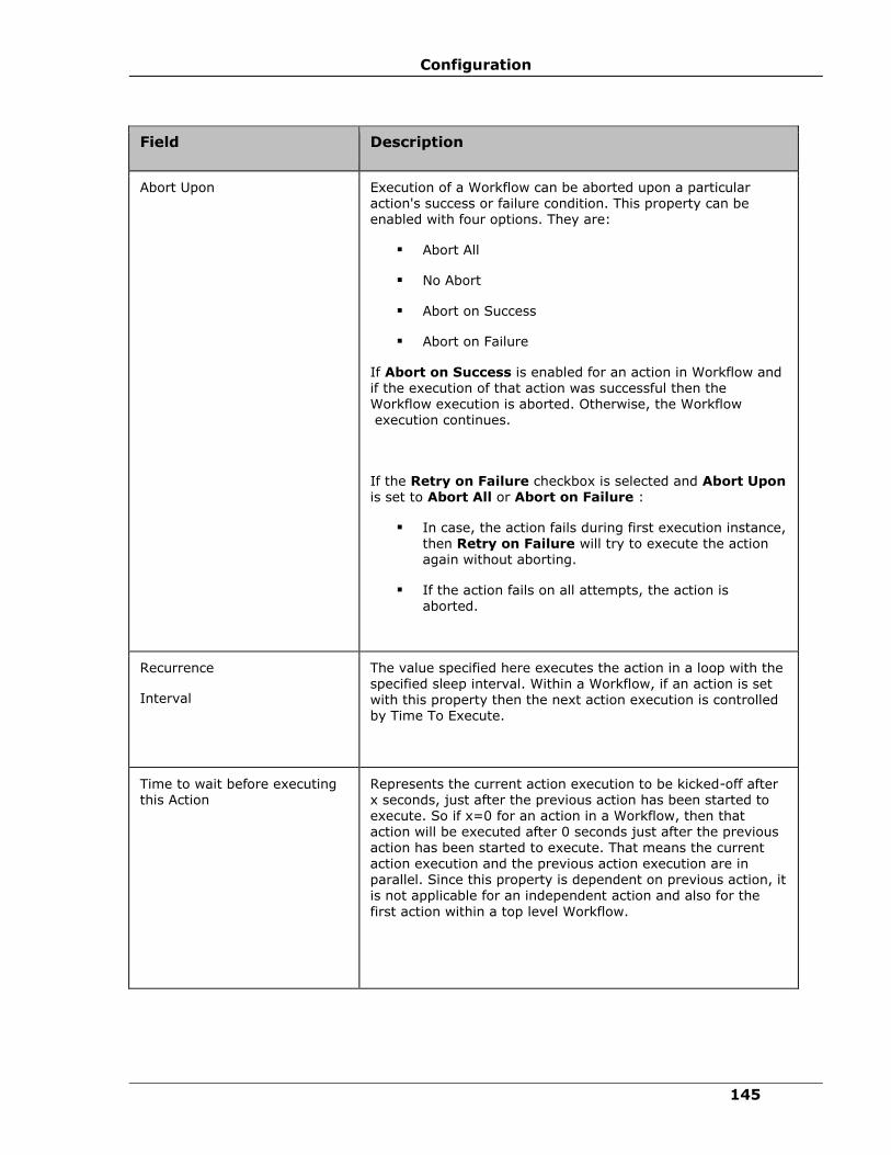
Configuration
145
Field Description
Abort Upon Execution of a Workflow can be aborted upon a particular action's success or failure condition. This property can be enabled with four options. They are:
▪ Abort All
▪ No Abort
▪ Abort on Success
▪ Abort on Failure
If Abort on Success is enabled for an action in Workflow and if the execution of that action was successful then the Workflow execution is aborted. Otherwise, the Workflow execution continues.
If the Retry on Failure checkbox is selected and Abort Upon is set to Abort All or Abort on Failure :
▪ In case, the action fails during first execution instance, then Retry on Failure will try to execute the action again without aborting.
▪ If the action fails on all attempts, the action is
aborted.
Recurrence
Interval
The value specified here executes the action in a loop with the specified sleep interval. Within a Workflow, if an action is set with this property then the next action execution is controlled by Time To Execute.
Time to wait before executing this Action
Represents the current action execution to be kicked-off after x seconds, just after the previous action has been started to execute. So if x=0 for an action in a Workflow, then that action will be executed after 0 seconds just after the previous action has been started to execute. That means the current
action execution and the previous action execution are in parallel. Since this property is dependent on previous action, it is not applicable for an independent action and also for the
first action within a top level Workflow.
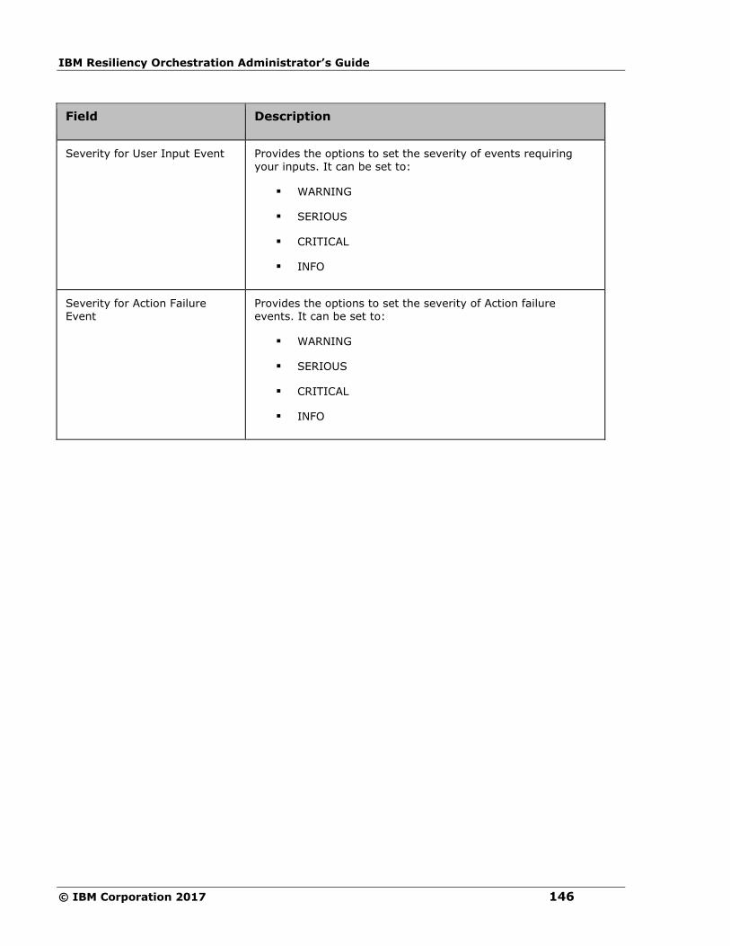
IBM Resiliency Orchestration Administrator’s Guide
© IBM Corporation 2017 146
Field Description
Severity for User Input Event Provides the options to set the severity of events requiring your inputs. It can be set to:
▪ WARNING
▪ SERIOUS
▪ CRITICAL
▪ INFO
Severity for Action Failure Event
Provides the options to set the severity of Action failure events. It can be set to:
▪ WARNING
▪ SERIOUS
▪ CRITICAL
▪ INFO
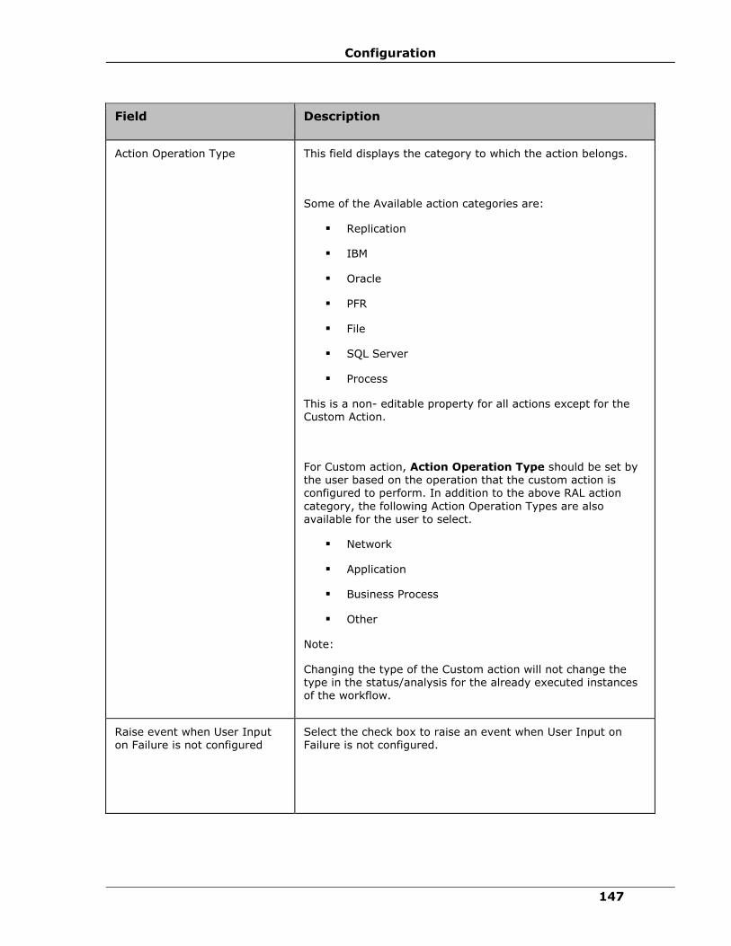
Configuration
147
Field Description
Action Operation Type This field displays the category to which the action belongs.
Some of the Available action categories are:
▪ Replication
▪ IBM
▪ Oracle
▪ PFR
▪ File
▪ SQL Server
▪ Process
This is a non- editable property for all actions except for the Custom Action.
For Custom action, Action Operation Type should be set by the user based on the operation that the custom action is configured to perform. In addition to the above RAL action
category, the following Action Operation Types are also available for the user to select.
▪ Network
▪ Application
▪ Business Process
▪ Other
Note:
Changing the type of the Custom action will not change the type in the status/analysis for the already executed instances of the workflow.
Raise event when User Input on Failure is not configured
Select the check box to raise an event when User Input on Failure is not configured.
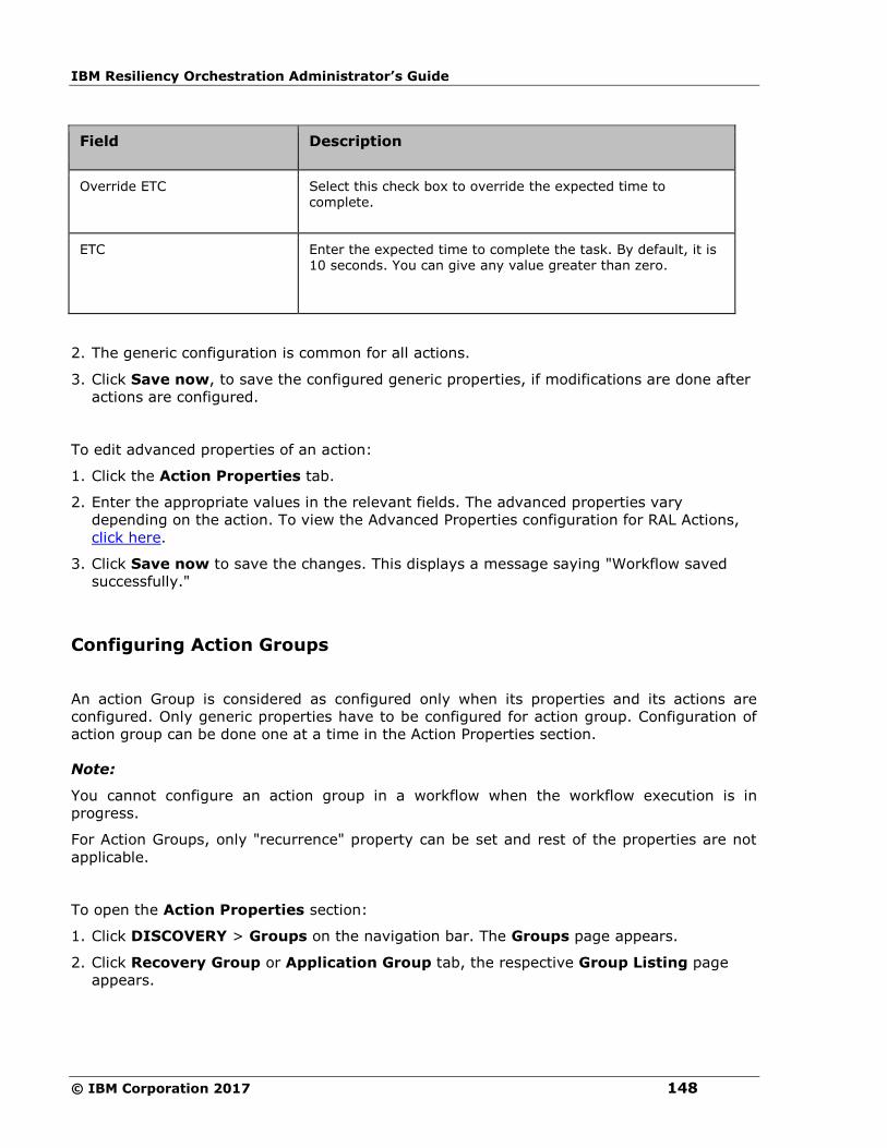
IBM Resiliency Orchestration Administrator’s Guide
© IBM Corporation 2017 148
Field Description
Override ETC Select this check box to override the expected time to complete.
ETC Enter the expected time to complete the task. By default, it is 10 seconds. You can give any value greater than zero.
2. The generic configuration is common for all actions.
3. Click Save now, to save the configured generic properties, if modifications are done after
actions are configured.
To edit advanced properties of an action:
1. Click the Action Properties tab.
2. Enter the appropriate values in the relevant fields. The advanced properties vary
depending on the action. To view the Advanced Properties configuration for RAL Actions,
click here.
3. Click Save now to save the changes. This displays a message saying "Workflow saved
successfully."
Configuring Action Groups
An action Group is considered as configured only when its properties and its actions are
configured. Only generic properties have to be configured for action group. Configuration of
action group can be done one at a time in the Action Properties section.
Note:
You cannot configure an action group in a workflow when the workflow execution is in
progress.
For Action Groups, only "recurrence" property can be set and rest of the properties are not
applicable.
To open the Action Properties section:
1. Click DISCOVERY > Groups on the navigation bar. The Groups page appears.
2. Click Recovery Group or Application Group tab, the respective Group Listing page
appears.
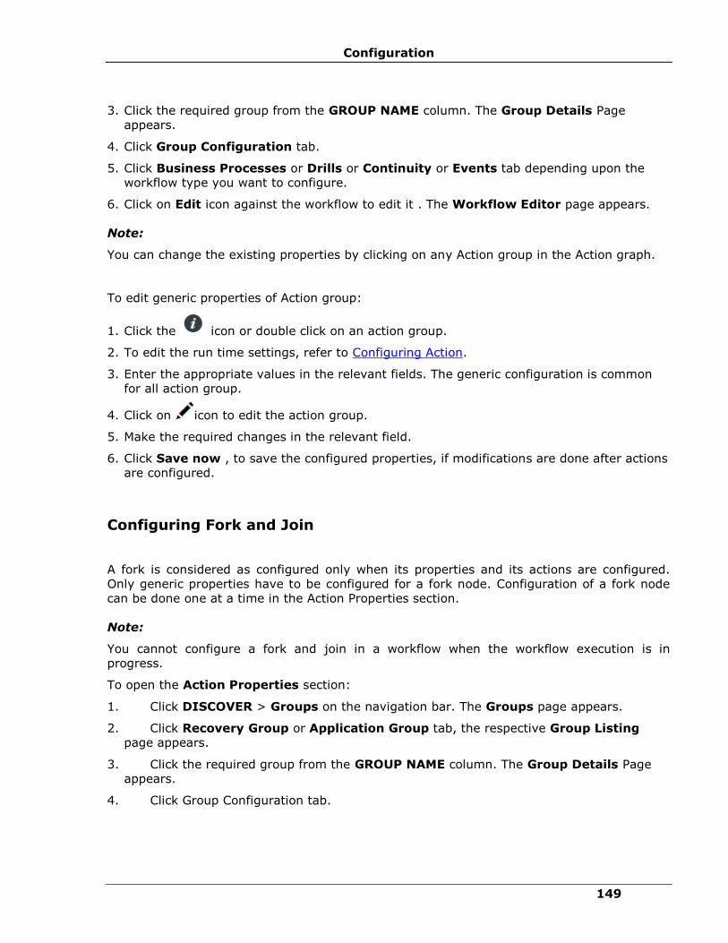
Configuration
149
3. Click the required group from the GROUP NAME column. The Group Details Page
appears.
4. Click Group Configuration tab.
5. Click Business Processes or Drills or Continuity or Events tab depending upon the
workflow type you want to configure.
6. Click on Edit icon against the workflow to edit it . The Workflow Editor page appears.
Note:
You can change the existing properties by clicking on any Action group in the Action graph.
To edit generic properties of Action group:
1. Click the icon or double click on an action group.
2. To edit the run time settings, refer to Configuring Action.
3. Enter the appropriate values in the relevant fields. The generic configuration is common
for all action group.
4. Click on icon to edit the action group.
5. Make the required changes in the relevant field.
6. Click Save now , to save the configured properties, if modifications are done after actions
are configured.
Configuring Fork and Join
A fork is considered as configured only when its properties and its actions are configured.
Only generic properties have to be configured for a fork node. Configuration of a fork node
can be done one at a time in the Action Properties section.
Note:
You cannot configure a fork and join in a workflow when the workflow execution is in
progress.
To open the Action Properties section:
1. Click DISCOVER > Groups on the navigation bar. The Groups page appears.
2. Click Recovery Group or Application Group tab, the respective Group Listing
page appears.
3. Click the required group from the GROUP NAME column. The Group Details Page
appears.
4. Click Group Configuration tab.
IBM Resiliency Orchestration Administrator’s Guide
© IBM Corporation 2017 150
5. Click Business Processes or Drills or Continuity or Events tab depending upon the
workflow type you want to configure.
6. Click on Edit icon against the workflow to edit it. The Workflow Editor page appears.
7. Click icon to add a fork, then add an action in between a fork and join.
Note
▪ Start of an action is connected to a fork and the end of an action is connected to a
join.
▪ You can change the existing properties by clicking on any Fork node in the workflow.
To edit generic properties of a fork node:
1. Click the icon or double click on a fork node.
2. To edit the run time settings, refer to Configuring Action.
3. Enter the appropriate values in the relevant fields. The generic configuration is common
for all action group.
4. Click on icon to edit the fork node.
5. Make the required changes in the relevant field.
6. Click Save now, to save the configured properties, if modifications are done after actions
are configured.
Deleting Actions/ Action Groups/Fork and Join
You can delete one or more actions, action groups and fork and a join from a workflow.
Some of the actions in a workflow are pre-defined. Such actions cannot be deleted and the
delete button will be disabled for them.
Note:
You cannot delete an action during a workflow execution. If you attempt to do so, a pop up
with message "PAN-SACM-4302: Could not configure Workflow as Workflow execution is in
progress" is displayed.
For a workflow, if you delete the last action in an Action Group, the Action Group also gets
deleted. However, the last action in a workflow cannot be deleted. If you want to delete the
last action, add a new action to the workflow and then delete the action.
To delete an action:
1. Click DISCOVER > Groups on the navigation bar. The Groups page appears.
2. Click Recovery Group or Application Group tab, the respective Group Listing page
appears.

Configuration
151
3. Click the required group from the GROUP NAME column. The Group Details Page
appears.
4. Click Group Configuration tab.
5. Click Business Processes or Drills or Continuity or Events tab depending upon the
workflow type you want to configure.
6. click on Edit icon against the workflow to edit it . The Workflow Editor page appears.
7. Click the Action/Action Group/Fork and join in the workflow editor that you want to
delete and click icon. A message box is displayed.
8. Click OK on the message box to delete the selected action/ action group/ fork and join.
Copy Workflow/ Copy Action
Copy Workflow
This a new feature added in Workflow manager to copy a workflow from any other group
with similar signature. This process is executed in series and will has a Wizard based
execution.
To copy a an existing workflow, perform the following steps:
1. Click Drills > Workflow list > Select Create New Workflow.
2. Select a group from the Group listing page.
Field Description
Name Provide the workflow name
Category Select one of the following category from the drop-down
list:
▪ Drills
▪ Business Process
3. Click Create new.
4. Click on Add to add the workflows.
5. Select the Workflow tab from the Add Window

IBM Resiliency Orchestration Administrator’s Guide
© IBM Corporation 2017 152
Field Description
Solution Signature Select one of the solution signature from the drop-down list.
Group Select a group from the list.
6. Select the workflow to be copied and click on icon from the list.
A message box is displayed confirming the copy action."Copying the workflow on canvas will
replace all the existing items on the canvas. Do you wish to continue?"
7. Click OK in the message box to replace the workflow with a new workflow.
Copy Action
This a new feature added in Workflow manager, which is used to copy an action from
Workflow.
1. Click Drills > Workflow list > Select Create New Workflow.
2. Select a group from the Group listing page.
Field Description
Name Provide the workflow name
Category Select one of the following category from the
drop-down list:
▪ Drills
▪ Business Process
3. Click Create new.
4. In Workflow Editor page, select an action.
5. Click on icon to copy the selected action.

Configuration
153
Zoom in and Zoom Out Workflow
To zoom in and out of the workflow, perform the following steps:
1. Click DISCOVER > Groups on the navigation bar. The Groups page appears.
2. Click Recovery Group or Application Group tab, the respective Group listing page
appears.
3. Click the required group from the GROUP NAME column to configure the workflow. The
Group Details Page appears.
4. Click Group Configuration tab.
5. Click Business Processes or Drills or Continuity or Events tab depending upon the
workflow type you want to configure.
6. Click on Edit icon against the workflow to edit it. The Workflow Editor page appears.
To Zoom in:
i. Click icon to Zoom in to the workflow.
To Zoom out:
i. Click icon to Zoom out of the workflow.
Creating new workflow
To create a workflow in a group, perform the following steps:
1. Click Drills>Summary tab.
2. Select a group from the Drills page.
3. Click on Create new button or Click Create new workflow. The user is directed to the
Select Workflow tab.
Field Description
Workflow Name Provide the workflow name
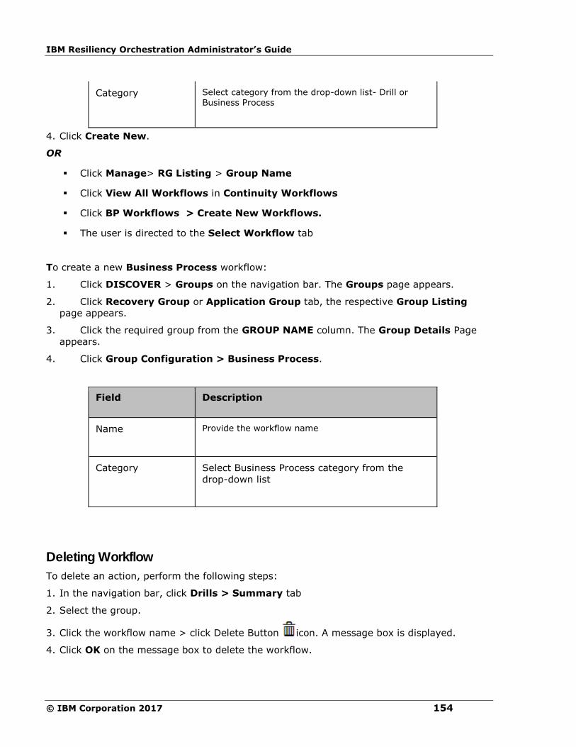
IBM Resiliency Orchestration Administrator’s Guide
© IBM Corporation 2017 154
Category Select category from the drop-down list- Drill or Business Process
4. Click Create New.
OR
▪ Click Manage> RG Listing > Group Name
▪ Click View All Workflows in Continuity Workflows
▪ Click BP Workflows > Create New Workflows.
▪ The user is directed to the Select Workflow tab
To create a new Business Process workflow:
1. Click DISCOVER > Groups on the navigation bar. The Groups page appears.
2. Click Recovery Group or Application Group tab, the respective Group Listing
page appears.
3. Click the required group from the GROUP NAME column. The Group Details Page
appears.
4. Click Group Configuration > Business Process.
Field Description
Name Provide the workflow name
Category Select Business Process category from the
drop-down list
Deleting Workflow
To delete an action, perform the following steps:
1. In the navigation bar, click Drills > Summary tab
2. Select the group.
3. Click the workflow name > click Delete Button icon. A message box is displayed.
4. Click OK on the message box to delete the workflow.

Configuration
155
Importing or Exporting a Workflow
You can import or export a workflow in the XML file format. This is possible only for the
workflows which are generic and are not pre-defined in IBM Resiliency Orchestration. The
XML files of the workflows contain complete configuration of all the actions in the workflow.
As a result, once the XML file is imported, parameter settings for all actions are automatically
populated. On the other hand, by exporting, you can take backup of a workflow in XML
format.
You may like to export a workflow of an existing Group and import it for a newly created
Group. However, while doing this, caution must be taken to change the Production and DR
components specified in the XML file before importing it for the new Group.
Import/ Export functionality can be accessed in the Workflow Details page.
To access Import/ Export functionality...
1 Click DISCOVER > Groups on the navigation bar. The Groups page appears.
2 Click Recovery Group or Application Group tab, the respective Group Listing page
appears.
3 Click the required group from the GROUP NAME column. The Group Details Page
appears.
4 Click the Group Configuration tab.
5 Click Business Processes or Tests or Continuity or Events tab depending upon the
workflow which you want to import/export.
6 Click the link for the desired operation. The Workflow editor page appears.
To Import Workflow
1 Click on Add button.
2 Click on the workflow tab.
3 Click the Import Workflow button and import the file.
To Export Workflow
1 Click on the Export button at the footer.
To import a XML file for a workflow...
Importing a workflow will overwrite the existing workflow. Make sure that you have specified
the right components in the XML file for the desired Group.
For the import to be successful, the workflow must not be running.
1 Open the Workflow Editor page.
2 Click on Add button.
IBM Resiliency Orchestration Administrator’s Guide
© IBM Corporation 2017 156
3 Click on the workflow tab.
4 Click the Import Workflow button and import the file.
5 Click Browse to open the Choose file dialog box.
6 Select the desired XML file and click Open in the Choose file dialog box.
To export workflow for a Group...
1 Open the Workflow Editor page.
2 Click the Export button.
3 A pop up message is displayed as "Will export the last published workflow?"
4 Click Yes to open File Download dialog box.
5 Click Save to open the Save as dialog box to save the XML file at the desired location.
Note:
▪ While exporting a workflow with Skip property 'Disabled', the XML file will not contain
any tags with respect to skip for that action. However, when the workflow is exported
with Skip property 'Enabled', the XML file will have skip tag for that action. The case is
similar for 'Single step'.
▪ When importing a workflow from a file, the version number of the imported workflow
goes through a validation check of supported RAL versions. If the version of the
imported workflow is not supported, the following message is displayed.
"Import Failed!
The Current Recovery Automation Library (RAL) Version is <ral_version>
The version of the workflow that you are trying to import is <version>
This is not compatible with the current RAL Version.
The versions of the following actions are not compatible with current RAL Version.
Action Name = <action_name>, Version = <action_version>
Action Name = <action_name>, Version = <action_version>
Action Name = <action_name>, Version = <action_version>
Action Name = <action_name>, Version = <action_version>
Action Name = <action_name>, Version = <action_version>
Please consult the IBM Resiliency Orchestration Workflow Version Compatibility
Matrix/User Manual before importing the Workflow"

Configuration
157
▪ While exporting a workflow, you have two options. One is to open it in the browser
directly without saving it and the other is to save it onto a local disk. The Open option
does not work. Use only Save button to save a workflow onto the disk and open later
with an editor of your choice.
Scheduling Business Process Workflow / Drills
You can schedule a business process workflow for one of the following:
▪ Schedule to run just once.
▪ Schedule to run daily at a particular time or at recurring intervals.
▪ Schedule to run weekly on a particular day and time.
▪ Schedule to run monthly on a particular day and time.
1. Click DISCOVER > Groups on the navigation bar. The Groups page appears.
2. Click Recovery Group or Application Group tab, the respective Group listing page
appears.
3. Click the required group from the GROUP NAME column to configure the workflow.
The Group Details Page appears.
4. Click Group Configuration tab.
5. Click Business Processes or Drills tab depending upon the workflow type you want to
configure.
6. Click on Edit icon against the workflow to edit it . The Workflow Editor page appears.
7. Click Publish.
8. Again click Publish Workflow.
The Workflow Listing page appears.
9. Click the Scheduler icon for the published Workflow accordingly.The Schedule
Workflow pop-up appears with the Group name and Workflow name.
10. Click on the Enable schedule checkbox to schedule the Workflow.
Field Description
Recurrence Frequency
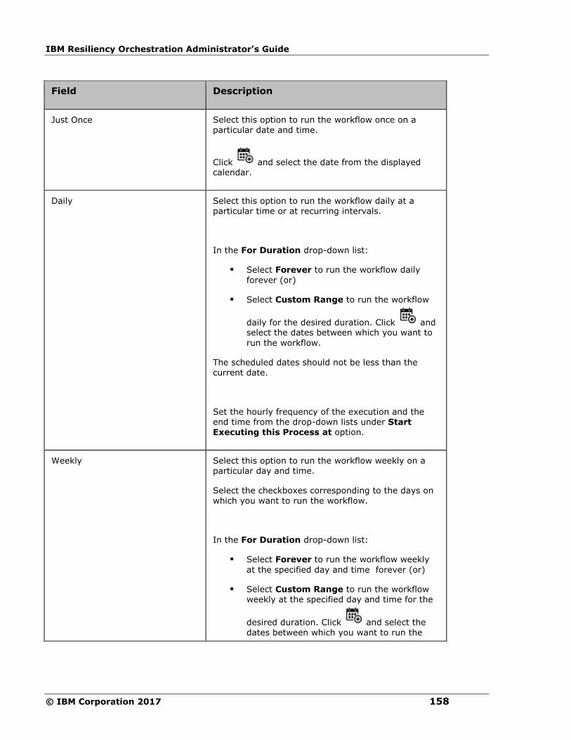
IBM Resiliency Orchestration Administrator’s Guide
© IBM Corporation 2017 158
Field Description
Just Once Select this option to run the workflow once on a particular date and time.
Click and select the date from the displayed calendar.
Daily Select this option to run the workflow daily at a particular time or at recurring intervals.
In the For Duration drop-down list:
▪ Select Forever to run the workflow daily
forever (or)
▪ Select Custom Range to run the workflow
daily for the desired duration. Click and select the dates between which you want to
run the workflow.
The scheduled dates should not be less than the current date.
Set the hourly frequency of the execution and the end time from the drop-down lists under Start Executing this Process at option.
Weekly Select this option to run the workflow weekly on a particular day and time.
Select the checkboxes corresponding to the days on which you want to run the workflow.
In the For Duration drop-down list:
▪ Select Forever to run the workflow weekly
at the specified day and time forever (or)
▪ Select Custom Range to run the workflow weekly at the specified day and time for the
desired duration. Click and select the dates between which you want to run the
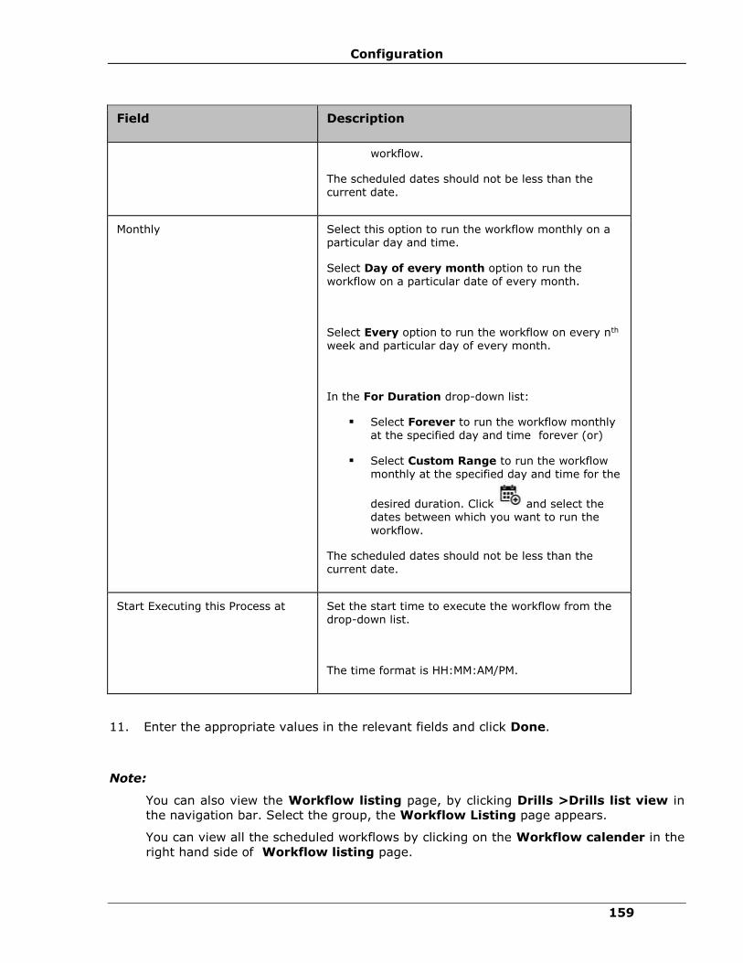
Configuration
159
Field Description
workflow.
The scheduled dates should not be less than the current date.
Monthly Select this option to run the workflow monthly on a particular day and time.
Select Day of every month option to run the workflow on a particular date of every month.
Select Every option to run the workflow on every nth week and particular day of every month.
In the For Duration drop-down list:
▪ Select Forever to run the workflow monthly at the specified day and time forever (or)
▪ Select Custom Range to run the workflow monthly at the specified day and time for the
desired duration. Click and select the dates between which you want to run the
workflow.
The scheduled dates should not be less than the current date.
Start Executing this Process at Set the start time to execute the workflow from the drop-down list.
The time format is HH:MM:AM/PM.
11. Enter the appropriate values in the relevant fields and click Done.
Note:
You can also view the Workflow listing page, by clicking Drills >Drills list view in
the navigation bar. Select the group, the Workflow Listing page appears.
You can view all the scheduled workflows by clicking on the Workflow calender in the
right hand side of Workflow listing page.
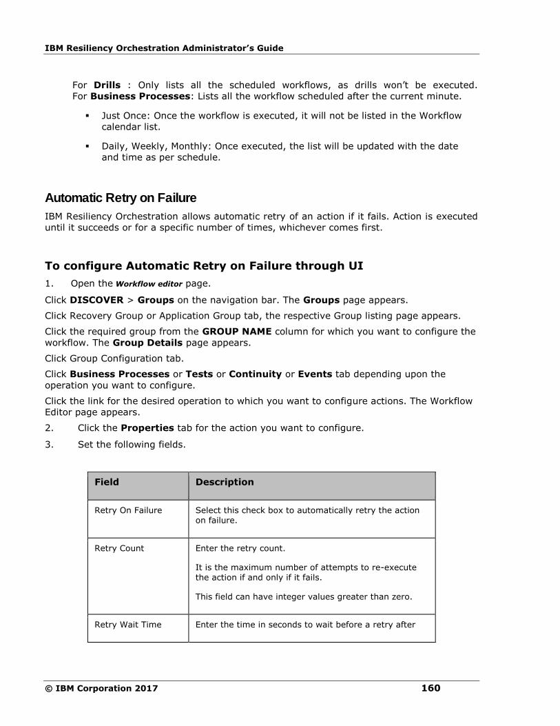
IBM Resiliency Orchestration Administrator’s Guide
© IBM Corporation 2017 160
For Drills : Only lists all the scheduled workflows, as drills won’t be executed.
For Business Processes: Lists all the workflow scheduled after the current minute.
▪ Just Once: Once the workflow is executed, it will not be listed in the Workflow
calendar list.
▪ Daily, Weekly, Monthly: Once executed, the list will be updated with the date
and time as per schedule.
Automatic Retry on Failure
IBM Resiliency Orchestration allows automatic retry of an action if it fails. Action is executed
until it succeeds or for a specific number of times, whichever comes first.
To configure Automatic Retry on Failure through UI
1. Open the Workflow editor page.
Click DISCOVER > Groups on the navigation bar. The Groups page appears.
Click Recovery Group or Application Group tab, the respective Group listing page appears.
Click the required group from the GROUP NAME column for which you want to configure the
workflow. The Group Details page appears.
Click Group Configuration tab.
Click Business Processes or Tests or Continuity or Events tab depending upon the
operation you want to configure.
Click the link for the desired operation to which you want to configure actions. The Workflow
Editor page appears.
2. Click the Properties tab for the action you want to configure.
3. Set the following fields.
Field Description
Retry On Failure Select this check box to automatically retry the action on failure.
Retry Count Enter the retry count.
It is the maximum number of attempts to re-execute the action if and only if it fails.
This field can have integer values greater than zero.
Retry Wait Time Enter the time in seconds to wait before a retry after

Configuration
161
Field Description
failure.
This field can have integer values greater than zero.
Note:
▪ In case the Retry on Failure checkbox is selected and the Execution Mode is set as
Manual, then action is re-executed without asking the user again.
▪ If the Retry on Failure checkbox is selected and Inform Upon is set to Inform All or Inform
on Failure:
▪ Notification is done only once after the execution of the action.
▪ If the action fails during first execution instance, then Retry on Failure will try to
execute the action again without notification.
▪ If the action fails on all attempts, the user is notified and has the option to
continue or quit or retry.
▪ If the Retry on Failure checkbox is selected and Abort Upon is set to Abort All or Abort
on Failure:
▪ If the action fails during first execution instance, then Retry on Failure will try to
execute the action again without aborting.
▪ If the action fails on all attempts, the action is aborted.
▪ When the Retry on Failure checkbox is selected, is Retryable will be set to "Yes".
Single Stepping Actions in Workflows
Enabling single step will wait for user confirmation while executing each action in the
workflow. Single step specifies that there is some user intervention to execute the action.
Use Enable Single Step to raise an Input Required event.
To enable this feature, perform the following:
1. Click DISCOVER > Groups on the navigation bar. The Groups page appears.
2. Click Recovery Group or Application Group tab, the respective Group listing page
appears.
IBM Resiliency Orchestration Administrator’s Guide
© IBM Corporation 2017 162
3. Click the required group from the GROUP NAME column to configure the workflow. The
Group Details Page appears.
4. Click the Group Configuration tab.
5. Click the Business Processes or Drills or Continuity or Events tab depending upon the
operation you want to configure.
6. Click the link for the desired workflow. The Workflow Editor page appears.
7. Click Publish.
8. Click the Enable Single Step button to enabling single stepping.
To disable single stepping, follow the steps from 1 to 6 and click the Disable Single Step
button.
Note:
▪ In case the Skip checkbox is selected and the Single Step is Enabled, then action is
skipped without manual intervention.
▪ In case the Execution Mode is set as Auto and the Single Step is Enabled, the
workflow will wait for user confirmation to execute.
▪ In case the Execution Mode is set as Manual and the Single Step is Enabled, the
workflow will wait for user confirmation only once to execute.
Synchronizing Workflow with RPO/RTO
It is possible that the Workflow being executed is also being considered for RPO/RTO
calculation. To avoid this conflict, you can synchronize the Workflow with RPO/RTO
calculation mechanism.
To do the synchronization, perform the following steps:
1. Identify the Action/Action Group that can probably conflict with RPO/RTO mechanism.
2. Insert Group Lock action at the start and end of the Action/Action Group. Refer Adding
Actions/ Action Groups for procedural details.
3. In the Action graph, click the Group Lock action at the start of the Action/Action
Group.
4. Click the Advanced tab in the Action Properties section.
5. Select the Acquire Lock option to associate lock acquisition action to the Group Lock
action.
6. Click Finish.
7. In the Action graph, click the Group Lock action at the end of the Action/Action Group.
Configuration
163
8. Click the Advanced tab in the Action Properties section.
9. Select the Release Lock radio button to associate lock removal action to the Group
Lock action.
10. Click Finish.
This synchronization is performed on first-come-first-serve basis. Only after release of the
Group Lock, the conflicting action can resume.
Publish/ Save as a Draft
Publish
This feature is added in Workflow manager to publish completely configured workflow. To
start the execution, the workflow should be published.
To publish a workflow, perform the following steps:
1. Click DISCOVER > Groups on the navigation bar. The Groups page appears.
2. Click Recovery Group or Application Group tab, the respective Group listing page
appears.
3. Click the required group from the GROUP NAME column to configure the workflow. The
Group Details Page appears.
4. Click Group Configuration tab.
5. Click Business Processes or Drills or Continuity or Events tab depending upon the
workflow type you want to configure.
6. Click on Edit icon against the workflow to edit it . The Workflow Editor page appears.
7. Click Next.
8. Click Publish button to publish the workflow.
Save as a Draft
This feature is added in Workflow manager to provide the user with an option to save the
workflow created as a draft. To start the execution, the workflow should be published.
To save the workflow in draft state, perform the following steps:
1. Click DISCOVER > Groups on the navigation bar. The Groups page appears.
2. Click Recovery Group or Application Group tab, the respective Group listing page
appears.
3. Click the required group from the GROUP NAME column to configure the workflow.
4. Click Group Configuration tab.

IBM Resiliency Orchestration Administrator’s Guide
© IBM Corporation 2017 164
5. Click Business Processes or Drills or Continuity or Events tab depending upon the
workflow type you want to configure.
6. Click on Edit icon against the workflow to edit it. The Workflow Editor page appears.
7. Click Next.
8. Click Save as a draft in the Publish Workflow page.
Previewing Workflow
To preview a workflow, perform the following steps:
1. Click Drills > View Workflow Dashboard > Select Create New Workflow.
2. Select a group from the Group listing page.
3. Click the icon corresponding to the workflow that you want to preview.
Workflow Version History/ Rollback
▪ Workflow Version History is a new features added in Workflow Manager, the goal is to
track the workflow level changes such as adding/deleting actions, updating workflow
properties, also to track the action level changes within a workflow. Action level
changes like action basic/advanced properties configuration, property values. Also to
track any changes to the custom script by using the checksum compare feature
between workflow versions.
▪ Every time a workflow is published, the workflow version is saved.
▪ Rollback is a new feature added to the Workflow Manager, is used to rollback the
previous workflow configured.
To view the published workflow versions, perform the following procedure:
1. Click DISCOVER > Groups on the navigation bar. The Groups page appears.
2. Click Recovery Group or Application Group tab, the respective Group listing page
appears.
3. Click the required group from the GROUP NAME column. The Group Details Page
appears.
4. Click Group Configuration tab.
5. Click Business Processes or Drills or Continuity or Events tab depending upon the
workflow type you want to configure.
6. Click on Edit icon against the workflow to edit it . The Workflow Editor page appears.
7. Click on the Version button at the footer.
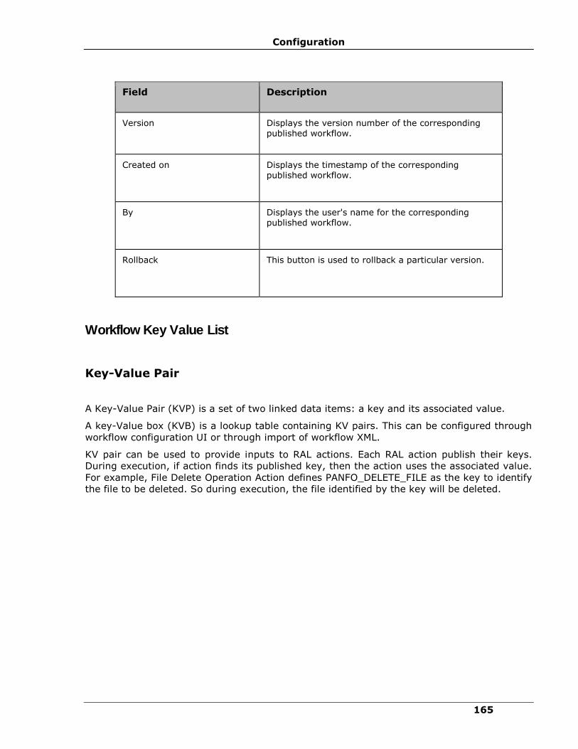
Configuration
165
Field Description
Version Displays the version number of the corresponding published workflow.
Created on Displays the timestamp of the corresponding published workflow.
By Displays the user's name for the corresponding published workflow.
Rollback This button is used to rollback a particular version.
Workflow Key Value List
Key-Value Pair
A Key-Value Pair (KVP) is a set of two linked data items: a key and its associated value.
A key-Value box (KVB) is a lookup table containing KV pairs. This can be configured through
workflow configuration UI or through import of workflow XML.
KV pair can be used to provide inputs to RAL actions. Each RAL action publish their keys.
During execution, if action finds its published key, then the action uses the associated value.
For example, File Delete Operation Action defines PANFO_DELETE_FILE as the key to identify
the file to be deleted. So during execution, the file identified by the key will be deleted.

IBM Resiliency Orchestration Administrator’s Guide
© IBM Corporation 2017 166
Adding Key Value Pair
To add a key value pair to the Key Value List:
1. Click DISCOVER > Groups on the navigation bar. The Groups page appears.
2. Click Recovery Group or Application Group tab, the respective Group listing page
appears.
3. Click the required group from the GROUP NAME column. The Group Details page
appears.
4. In the Group Details page, click Group Configuration tab. It further displays a list of
tabs. The Business Process, Drills, Continuity and Events tabs allows to add a key
value pair.
5. Click the desired tab and select any name (BCO Name, Drill Name, Event ID,
BUSINESS PROCESS NAME column) in the group.
6. In the Workflow Editor page that opens, click the Key Value Pairs link. The Workflow
Key Value List window opens.
OR
5. Click Publish, Publish workflow page appears. The Workflow Key Value List window
opens.
Field Description
Key A key is a string that uniquely identifies a specific property of an object/entity.
This field can contain only string datatype.
Keys must begin with an alphabet, and must not contain whitespace.
Value A Value is the data/property that is identified by its Key.
This field can contain only string datatype.
Click Add to enter the key and value to the Key Value List.
Key Value List A Key Value List is a set of two linked data items: a Key, and its Value.

Configuration
167
6. Enter the appropriate information in the relevant fields.
7. Click Add key value button to save the changes.
Group level Key Value configuration
Group level KV are the global key value at group level which will be available to all the
Workflows in Test Exercise, Business Process and BCOs.
CLI to Add/Update/Delete group key value are available under
$EAMSROOT/IBMUtil/AG/AGTestClient.sh
steps to add global kv (Add - operation)
1. Execute AGTestClient.sh script and type “groupkv”.
2. It prompt you to enter operation 'Enter Add, Update, Delete operation of global KV’, enter
Add.
3. Enter the Enter Group Name under which you want to create global KV
4. Enter Key Name, e.g. MountPointList_DR_Redo and then Enter Values Name, e.g.
/findb_redo1, /findb_redo2, /findb_redo3, click enter.
5. Your global KV will be saved.
Following are the steps to update global key value (Update - operation)
1. Execute AGTestClient.sh script and type “groupkv”.
2. It prompt you to enter operation 'Enter Add, Update, Delete operation of global KV’,enter
Update
3. Enter the Enter Group Name under which you want to update global KV
4. Enter Key Name, e.g. MountPointList_DR_Redo and then Enter Values Name to be update,
e.g. /findb_redo1, /findb_redo4, /findb_redo8, click enter.
5. Your global KV will be updated.
Following are the Steps to delete global key value (Delete - operation)
1. Execute AGTestClient.sh script and type “groupkv”.
2. It prompt you to enter operation 'Enter Add, Update, Delete operation of global KV’,enter
Delete
3. Enter the Enter Group Name under which you want to delete global KV
4. Enter Key Name, e.g. MountPointList_DR_Redo and then for Enter Values Name,enter
nothing , click enter.
5. Your global KV will be deleted.

IBM Resiliency Orchestration Administrator’s Guide
© IBM Corporation 2017 168
Modifying Key Value Pair
To modify a key value pair:
1. Open the Workflow Key Value List window. For more information, refer to Adding Key
Value Pair.
2. Select the key value pair you want to edit from the Key Value List field and click Edit.
3. Modify the key name in the Key field.
4. Modify the value for the key in the Value field.
5. Click Add to add the modified key value pair to the Key Value List.
6. Click Add key value to save the changes.
Removing Key Value Pair
To remove a key value pair from the Key Value List:
1. Open the Workflow Key Value List window. For more information, refer to Adding Key
Value Pair.
2. Select the key value pair you want to delete from the Key Value List field.
3. Click icon to delete the key value pair from the Key Value List.
4. Click on Save now to save the changes
Note:
Currently, removing all the key-value pairs associated with a workflow using the above
procedure submits and empties the key-value list to the back-end, which will overwrite the
existing values associated with a workflow.
Applying the Key Value
You can apply the user defined or pre-defined keys through UI or XML file.
Through UI:
1. Open the Workflow details page.
2. Click the Action properties tab of the relevant RAL action.
3. Use the pre-defined or user defined key.
4. Save the action.

Configuration
169
Through XML:
1. Export the current workflow. The exported workflow is saved in XML format.
2. Open the XML file in text editor.
3. Write the XML tags using pre-defined or user defined keys.
4. Save the XML file.
5. Import the saved XML file.
Workflow Configuration Limitations
Following are the invalid/unsupported workflow configurations:
▪ A recurring action should not be configured with "Time to wait before executing this
Action". The behavior is unpredictable if configured.
▪ An action within a recurring action group should not be configured with "recurrence
interval". The behavior is unpredictable if configured.
▪ In a workflow, an action group can contain only RAL actions, not another Action
Group.
▪ Workflow should not be created where the success path and failure path of
Actions/Action Groups forms loop/cycle. The behavior is unpredictable if configured
and user should not try to delete action/actiongroup using UI.
For example, assume a workflow is being created with three actions (say A1, A2, A3).
If A1's next action is A2 and A2's next action is A3 and A3's next action is either A1 or
A2 then it forms a cycle/loop among the actions. Such configuration results in
unpredictable behaviour like high CPU utilization resulting in software/system crash. If
any workflow has cycle/loop then the only workaround is to import a new workflow
without cycles/loops.
Configuring Approver List
To view the Workflow Details, go to Adding Key Value List.
The following steps can be performed to configure the Approver list.
1. In the Workflow Editor page, Click Next.
2. In Publish worklow page, select the checkbox to select the approvers for execution.
3. Click on Publish Workflow.
Note:
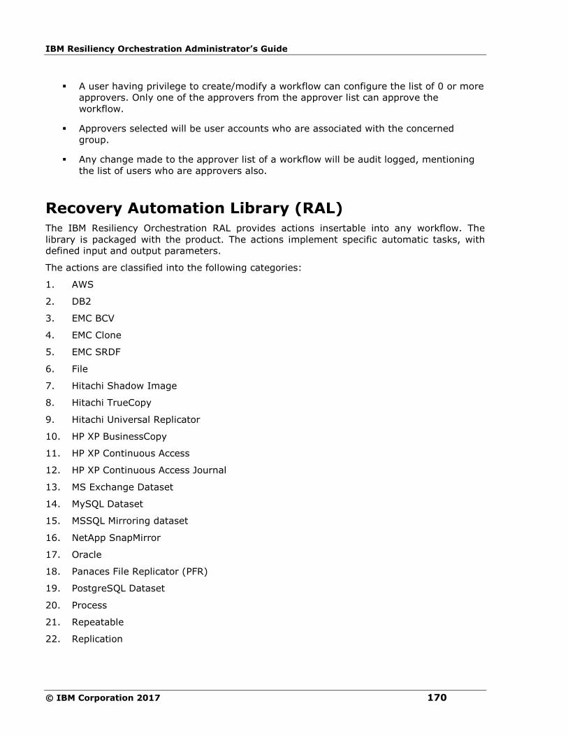
IBM Resiliency Orchestration Administrator’s Guide
© IBM Corporation 2017 170
▪ A user having privilege to create/modify a workflow can configure the list of 0 or more
approvers. Only one of the approvers from the approver list can approve the
workflow.
▪ Approvers selected will be user accounts who are associated with the concerned
group.
▪ Any change made to the approver list of a workflow will be audit logged, mentioning
the list of users who are approvers also.
Recovery Automation Library (RAL)
The IBM Resiliency Orchestration RAL provides actions insertable into any workflow. The
library is packaged with the product. The actions implement specific automatic tasks, with
defined input and output parameters.
The actions are classified into the following categories:
1. AWS
2. DB2
3. EMC BCV
4. EMC Clone
5. EMC SRDF
6. File
7. Hitachi Shadow Image
8. Hitachi TrueCopy
9. Hitachi Universal Replicator
10. HP XP BusinessCopy
11. HP XP Continuous Access
12. HP XP Continuous Access Journal
13. MS Exchange Dataset
14. MySQL Dataset
15. MSSQL Mirroring dataset
16. NetApp SnapMirror
17. Oracle
18. Panaces File Replicator (PFR)
19. PostgreSQL Dataset
20. Process
21. Repeatable
22. Replication

Configuration
171
23. SQL Server
24. VMware vCenter
25. Workflow
26. Zerto
Note:
▪ Hitachi Replicator is classified into three categories:
▪ Hitachi TrueCopy
▪ Hitachi Universal Replicator
▪ Hitachi Shadow Image
▪ EMC SRDF Replication is classified into two categories:
▪ EMC SRDF
▪ EMC BCV
▪ All IBM workflows use these RAL actions to implement their business continuity
operations.
▪ RAL provides complete use of RAL actions to end-users and support personal to
introduce new workflows or modify the extended existing workflows (BCO's, BPI's,
policies and DR drills).
▪ RAL actions can be exported/ imported to/ from XML files.
▪ Workflow execution will capture the output of the action, including any output
parameters returned by the actions.
▪ If there are multiple primary or DR servers in a group, then the user should select the
exact component server where the script/ command will be executed.
AWS
Create Route Table
Description
This action will add routing entry to a route table.
Inputs
Input Name Input Type Input Key Name Optional/
Mandatory
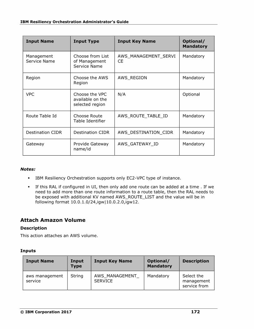
IBM Resiliency Orchestration Administrator’s Guide
© IBM Corporation 2017 172
Input Name Input Type Input Key Name Optional/
Mandatory
Management
Service Name
Choose from List
of Management
Service Name
AWS_MANAGEMENT_SERVI
CE
Mandatory
Region Choose the AWS
Region
AWS_REGION Mandatory
VPC Choose the VPC
available on the
selected region
N/A Optional
Route Table Id Choose Route
Table Identifier
AWS_ROUTE_TABLE_ID Mandatory
Destination CIDR Destination CIDR AWS_DESTINATION_CIDR Mandatory
Gateway Provide Gateway
name/id
AWS_GATEWAY_ID Mandatory
Notes:
▪ IBM Resiliency Orchestration supports only EC2-VPC type of instance.
▪ If this RAL if configured in UI, then only add one route can be added at a time . If we
need to add more than one route information to a route table, then the RAL needs to
be exposed with additional KV named AWS_ROUTE_LIST and the value will be in
following format 10.0.1.0/24,igw|10.0.2.0,igw12.
Attach Amazon Volume
Description
This action attaches an AWS volume.
Inputs
Input Name Input
Type Input Key Name Optional/
Mandatory Description
aws management
service
String AWS_MANAGEMENT_
SERVICE
Mandatory Select the
management
service from
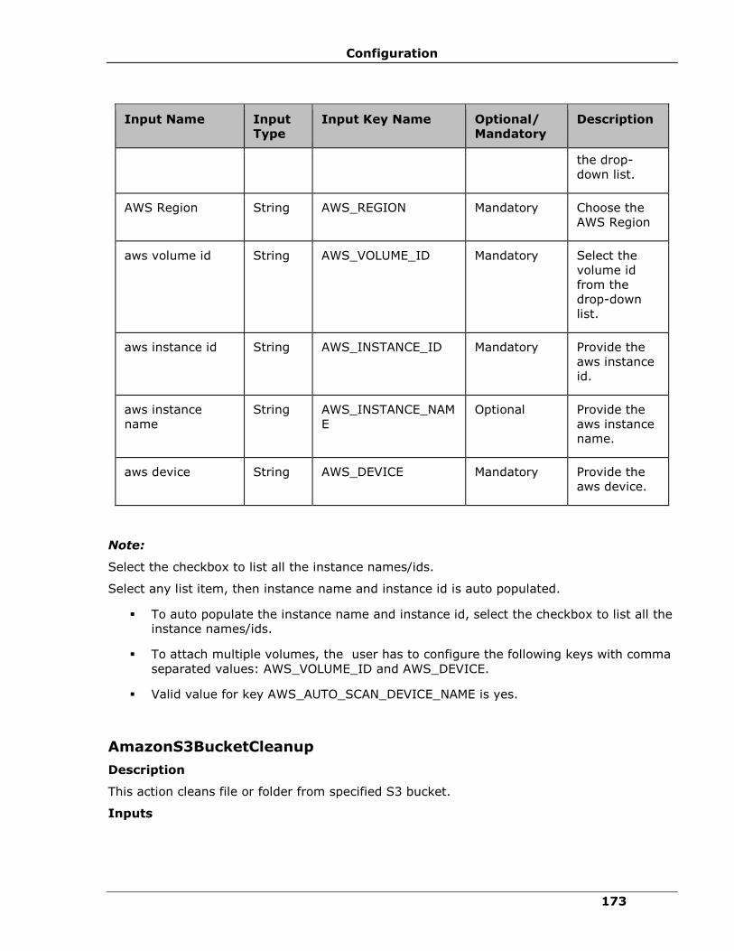
Configuration
173
Input Name Input
Type
Input Key Name Optional/
Mandatory
Description
the drop-
down list.
AWS Region String AWS_REGION Mandatory Choose the
AWS Region
aws volume id String AWS_VOLUME_ID Mandatory Select the
volume id
from the
drop-down
list.
aws instance id String AWS_INSTANCE_ID Mandatory Provide the
aws instance
id.
aws instance
name
String AWS_INSTANCE_NAM
E
Optional Provide the
aws instance
name.
aws device String AWS_DEVICE Mandatory Provide the
aws device.
Note:
Select the checkbox to list all the instance names/ids.
Select any list item, then instance name and instance id is auto populated.
▪ To auto populate the instance name and instance id, select the checkbox to list all the
instance names/ids.
▪ To attach multiple volumes, the user has to configure the following keys with comma
separated values: AWS_VOLUME_ID and AWS_DEVICE.
▪ Valid value for key AWS_AUTO_SCAN_DEVICE_NAME is yes.
AmazonS3BucketCleanup
Description
This action cleans file or folder from specified S3 bucket.
Inputs
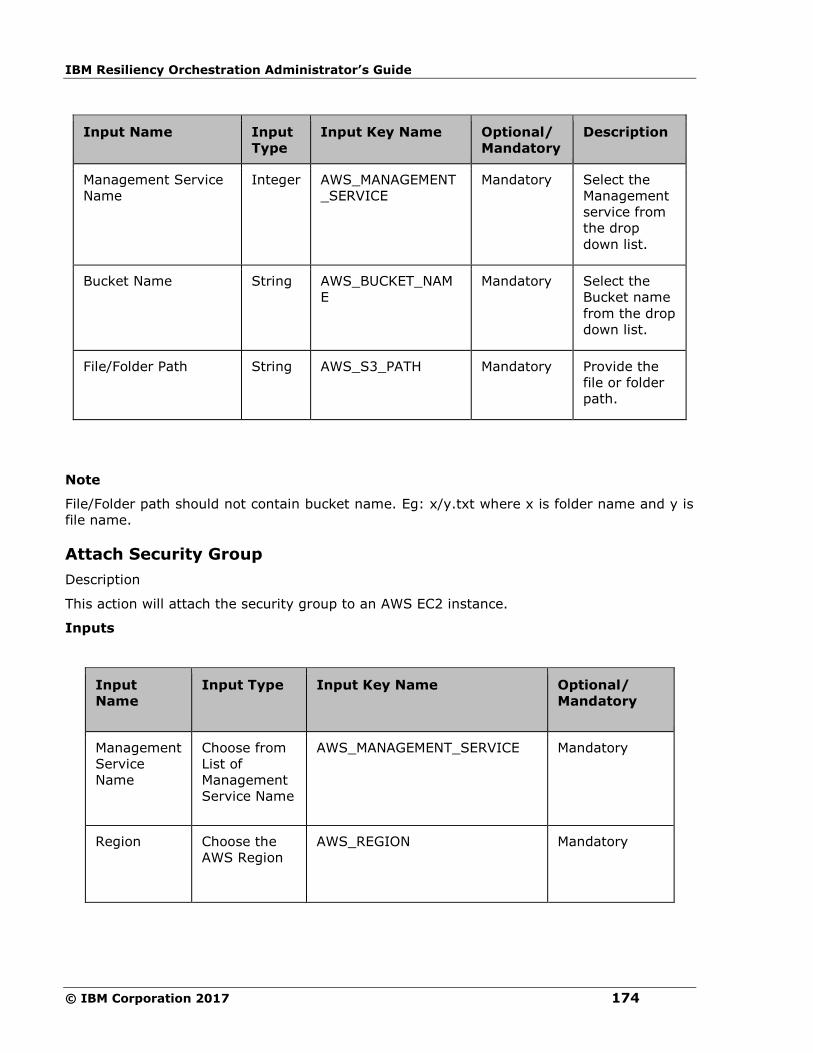
IBM Resiliency Orchestration Administrator’s Guide
© IBM Corporation 2017 174
Input Name Input
Type
Input Key Name Optional/
Mandatory
Description
Management Service
Name
Integer AWS_MANAGEMENT
_SERVICE
Mandatory Select the
Management
service from
the drop
down list.
Bucket Name String AWS_BUCKET_NAM
E
Mandatory Select the
Bucket name
from the drop
down list.
File/Folder Path String AWS_S3_PATH Mandatory Provide the
file or folder
path.
Note
File/Folder path should not contain bucket name. Eg: x/y.txt where x is folder name and y is
file name.
Attach Security Group
Description
This action will attach the security group to an AWS EC2 instance.
Inputs
Input
Name
Input Type Input Key Name Optional/
Mandatory
Management
Service
Name
Choose from
List of
Management
Service Name
AWS_MANAGEMENT_SERVICE Mandatory
Region Choose the
AWS Region
AWS_REGION Mandatory
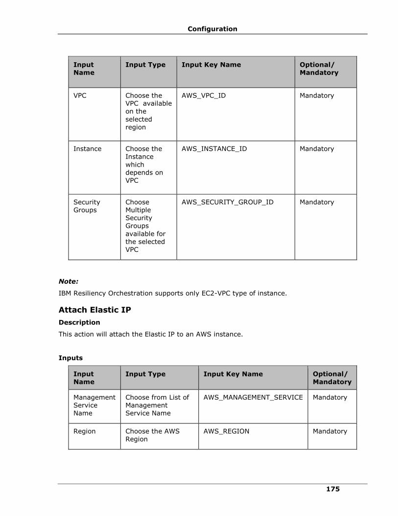
Configuration
175
Input
Name
Input Type Input Key Name Optional/
Mandatory
VPC
Choose the
VPC available
on the
selected
region
AWS_VPC_ID Mandatory
Instance
Choose the
Instance
which
depends on
VPC
AWS_INSTANCE_ID Mandatory
Security
Groups
Choose
Multiple
Security
Groups
available for
the selected
VPC
AWS_SECURITY_GROUP_ID Mandatory
Note:
IBM Resiliency Orchestration supports only EC2-VPC type of instance.
Attach Elastic IP
Description
This action will attach the Elastic IP to an AWS instance.
Inputs
Input
Name Input Type Input Key Name Optional/
Mandatory
Management
Service
Name
Choose from List of
Management
Service Name
AWS_MANAGEMENT_SERVICE Mandatory
Region Choose the AWS
Region
AWS_REGION Mandatory
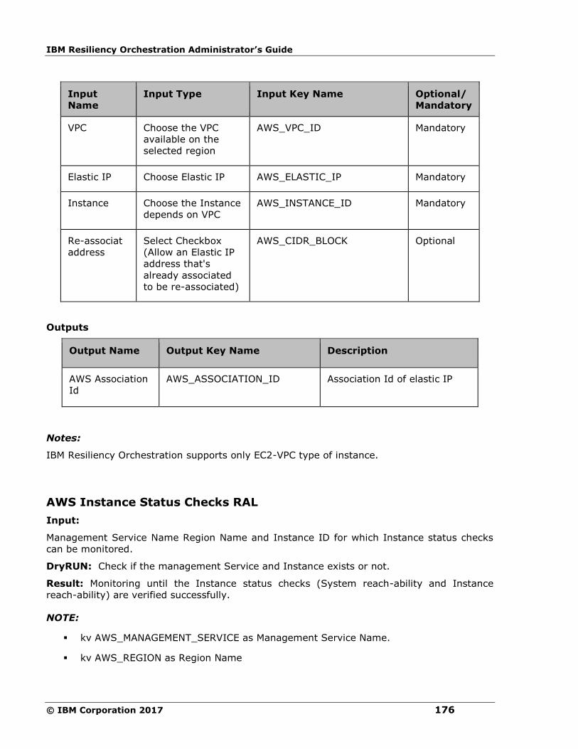
IBM Resiliency Orchestration Administrator’s Guide
© IBM Corporation 2017 176
Input
Name
Input Type Input Key Name Optional/
Mandatory
VPC Choose the VPC
available on the
selected region
AWS_VPC_ID Mandatory
Elastic IP Choose Elastic IP AWS_ELASTIC_IP Mandatory
Instance Choose the Instance
depends on VPC
AWS_INSTANCE_ID Mandatory
Re-associat
address
Select Checkbox
(Allow an Elastic IP
address that's
already associated
to be re-associated)
AWS_CIDR_BLOCK Optional
Outputs
Output Name Output Key Name Description
AWS Association
Id
AWS_ASSOCIATION_ID Association Id of elastic IP
Notes:
IBM Resiliency Orchestration supports only EC2-VPC type of instance.
AWS Instance Status Checks RAL
Input:
Management Service Name Region Name and Instance ID for which Instance status checks
can be monitored.
DryRUN: Check if the management Service and Instance exists or not.
Result: Monitoring until the Instance status checks (System reach-ability and Instance
reach-ability) are verified successfully.
NOTE:
▪ kv AWS_MANAGEMENT_SERVICE as Management Service Name.
▪ kv AWS_REGION as Region Name
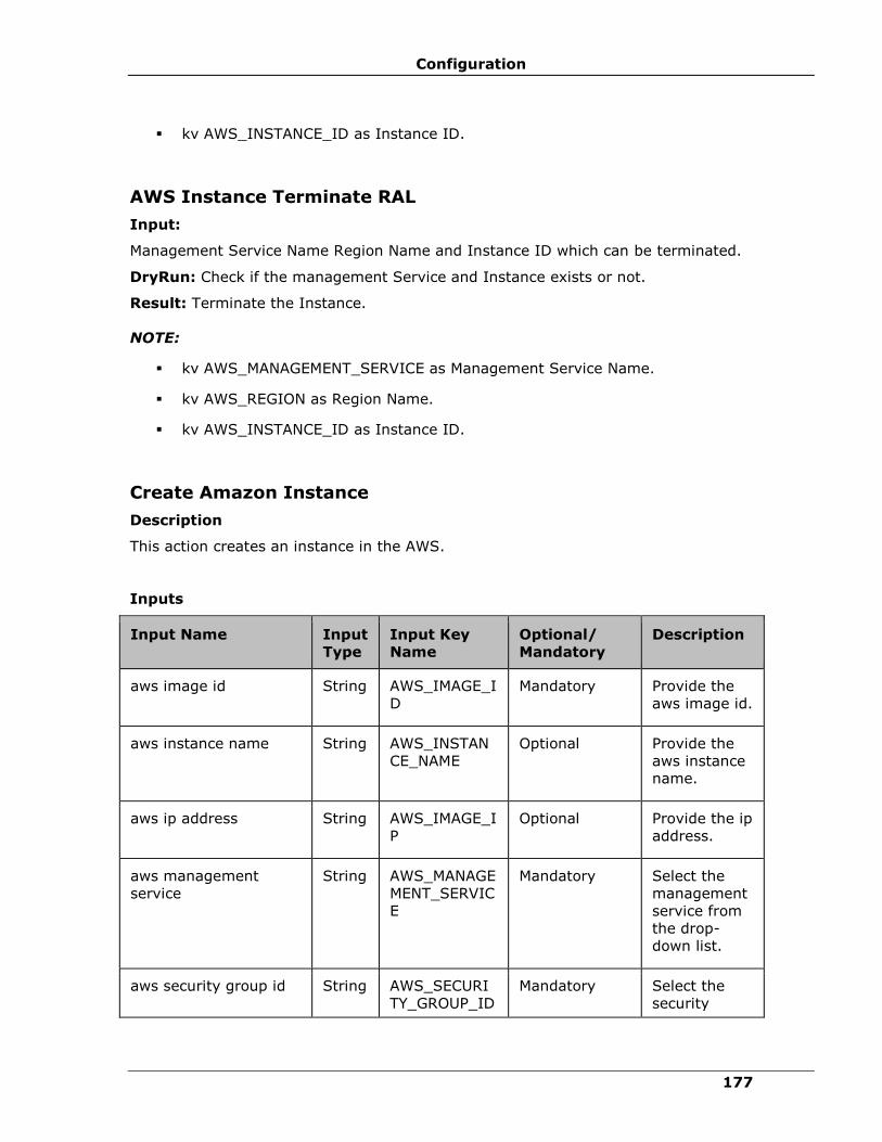
Configuration
177
▪ kv AWS_INSTANCE_ID as Instance ID.
AWS Instance Terminate RAL
Input:
Management Service Name Region Name and Instance ID which can be terminated.
DryRun: Check if the management Service and Instance exists or not.
Result: Terminate the Instance.
NOTE:
▪ kv AWS_MANAGEMENT_SERVICE as Management Service Name.
▪ kv AWS_REGION as Region Name.
▪ kv AWS_INSTANCE_ID as Instance ID.
Create Amazon Instance
Description
This action creates an instance in the AWS.
Inputs
Input Name Input
Type
Input Key
Name
Optional/
Mandatory
Description
aws image id String AWS_IMAGE_I
D
Mandatory Provide the
aws image id.
aws instance name String AWS_INSTAN
CE_NAME
Optional Provide the
aws instance
name.
aws ip address String AWS_IMAGE_I
P
Optional Provide the ip
address.
aws management
service
String AWS_MANAGE
MENT_SERVIC
E
Mandatory Select the
management
service from
the drop-
down list.
aws security group id String AWS_SECURI
TY_GROUP_ID
Mandatory Select the
security

IBM Resiliency Orchestration Administrator’s Guide
© IBM Corporation 2017 178
Input Name Input
Type
Input Key
Name
Optional/
Mandatory
Description
group id from
the drop-
down list.
aws subnet id String AWS_SUBNET
_ID
Mandatory Select the
subnet id
from the
drop-down
list.
aws key name String AWS_KEY_NA
ME
Mandatory Select the
key name
from the
drop-down
list.
aws instance type String AWS_INSTAN
CE_TYPE
Mandatory Select the
instance type
from the
drop-down
list.
region String AWS_REGION
Mandatory Choose the
AWS Region
Note:
▪ Select Show Saved Images check box for listing the saved aws images in IBM
Resiliency Orchestration.
▪ If Show Saved Images is selected, the instance name,image id ad IP address
fields are automatically populated.
Outputs
Output Name Output Key Name Description
aws instance id AWS_INSTANCE_ID AWS Instance Id
Note:
If this actions fails, the output key does not have any value.

Configuration
179
Pre-checks
▪ All input keys and values are checked.
▪ Credential check.
Create Amazon Volume
Description
This action creates a volume in the AWS .
Inputs
Input Name Input
Type
Input Key Name Optional/
Mandatory
Description
aws management
service
String AWS_MANAGEMENT_SERV
ICE
Mandatory Select the
management
service from
the drop-
down list.
Region String AWS_REGION Mandatory
Choose the
AWS Region
aws availability
zone
String
AWS_AVAILIBILITY_ZONE Mandatory Provide the
aws
availability
zone.
aws volume size Integ
er AWS_VOLUME_SIZE Optional(If
snapshot id is
configured
then it will be
optional,
otherwise
mandatory)
Provide the
aws volume
size.

IBM Resiliency Orchestration Administrator’s Guide
© IBM Corporation 2017 180
Input Name Input
Type
Input Key Name Optional/
Mandatory
Description
aws volume type String AWS_VOLUME_TYPE Mandatory Select the
dataset from
the drop-
down list.
aws provisioned
volume iops
Integ
er
AWS_PROVISIONED_VOLU
ME_IOPS
Mandatory Provide the
aws
provisioned
volume iops.
aws snapshot id String AWS_SNAPSHOT_ID Optional (if
the volume
size is
configured)
Select the
snapshot id
from the
drop-down
list.
Encryption String AWS_ENCRYPT_VOLUME Optional Select
checkbox
Note:
Select the check box to disable snapshot, if you want to create volume with the given size.
▪ To create multiple volumes, the user needs to configure either the Snapshot id or
volume size with comma separated values.
▪ keys : AWS_VOLUME_SIZE and AWS_VOLUME_TYPE (valid volume types are
io1,standard and gp2).
▪ User should specify the value to 0(for volume type other than io1) for key
AWS_PROVISIONED_VOLUME_IOPS.
▪ Valid values for key AWS_ENCRYPT_VOLUME are yes/no.
Outputs
Output Name Output Key Name Description
aws volume id AWS_VOLUME_ID AWS Volume Id
Note:
If this actions fails, the output key does not have any value.
Configuration
181
If you are creating volume from a snapshot and not specify a volume size, the default is the
snapshot size.
Pre-checks
▪ All input keys and values are checked.
▪ Credential check.

IBM Resiliency Orchestration Administrator’s Guide
© IBM Corporation 2017 182
Create Amazon Snapshot
Description
This action creates a Snapshot in the AWS.
Inputs
Input
Name
Input Type Input Key Name Optional/
Mandatory
Snapshot
Name
Enter
snapshot
name
AWS_SNAPSHOT_NAME Optional
Management
service
Name
Choose from
List of
Management
Service
Name
AWS_MANAGEMENT_SERVICE Mandatory
Region Choose the
AWS Region
AWS_REGION Mandatory
aws volume
id
Select the
Volume id
from the
drop-down
list
AWS_VOLUME_ID Mandatory
Outputs
Output Name Output Key Name Description
aws snapshot id AWS_SNAPSHOT_ID AWS Snapshot id
Note:
If this actions fails, the output key does not have any value.
Pre-checks
▪ All input keys and values are checked.
▪ Credential check.

Configuration
183
Create Internet Gateway
Description
This action will create a Internet Gateway and attach the same to VPC.
Inputs
Input
Name
Input
Type
Input Key Name Optional/
Mandatory
Description
Management
Service
Name
String AWS_MANAGEMENT_SERVICE Mandatory Choose from
List of
Management
Service
Name
Region String AWS_REGION Mandatory Choose the
AWS Region
VPC String AWS_VPC_ID Mandatory Choose the
VPC
available on
the selected
region
Name String AWS_INTERNET_GATEWAY_NAME Mandatory Internet
Gateway
Name
Output: AWS_GATEWAY_ID
Create Image RAL
This RAL creates image for the existing instance id.
Input:
Management Service Name, Region name, Instance ID, Image name.
DryRUN: Check the management Service and instance exists or not.
Result: Creates image for the existing instance id.
NOTE:
Input KV
▪ kv AWS_MANAGEMENT_SERVICE as Management Service Name
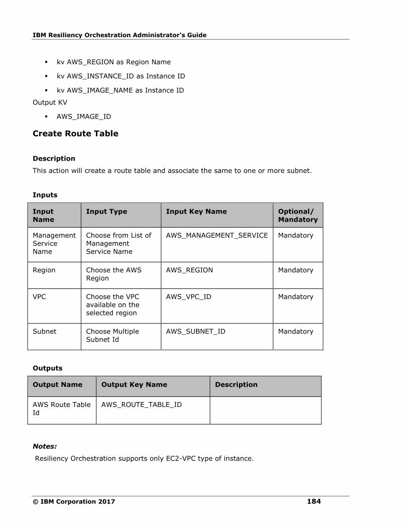
IBM Resiliency Orchestration Administrator’s Guide
© IBM Corporation 2017 184
▪ kv AWS_REGION as Region Name
▪ kv AWS_INSTANCE_ID as Instance ID
▪ kv AWS_IMAGE_NAME as Instance ID
Output KV
▪ AWS_IMAGE_ID
Create Route Table
Description
This action will create a route table and associate the same to one or more subnet.
Inputs
Input
Name
Input Type Input Key Name Optional/
Mandatory
Management
Service
Name
Choose from List of
Management
Service Name
AWS_MANAGEMENT_SERVICE Mandatory
Region Choose the AWS
Region
AWS_REGION Mandatory
VPC Choose the VPC
available on the
selected region
AWS_VPC_ID Mandatory
Subnet Choose Multiple
Subnet Id
AWS_SUBNET_ID Mandatory
Outputs
Output Name Output Key Name Description
AWS Route Table
Id
AWS_ROUTE_TABLE_ID
Notes:
Resiliency Orchestration supports only EC2-VPC type of instance.
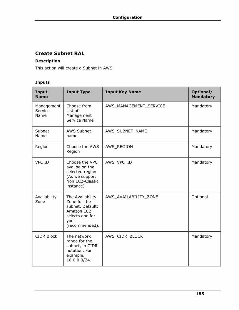
Configuration
185
Create Subnet RAL
Description
This action will create a Subnet in AWS.
Inputs
Input
Name
Input Type Input Key Name Optional/
Mandatory
Management
Service
Name
Choose from
List of
Management
Service Name
AWS_MANAGEMENT_SERVICE Mandatory
Subnet
Name
AWS Subnet
name
AWS_SUBNET_NAME Mandatory
Region Choose the AWS
Region
AWS_REGION Mandatory
VPC ID Choose the VPC
availbe on the
selected region
(As we support
Non EC2-Classic
instance)
AWS_VPC_ID Mandatory
Availability
Zone
The Availability
Zone for the
subnet. Default:
Amazon EC2
selects one for
you
(recommended).
AWS_AVAILABILITY_ZONE Optional
CIDR Block The network
range for the
subnet, in CIDR
notation. For
example,
10.0.0.0/24.
AWS_CIDR_BLOCK Mandatory
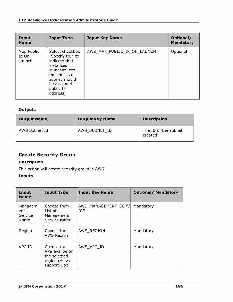
IBM Resiliency Orchestration Administrator’s Guide
© IBM Corporation 2017 186
Input
Name
Input Type Input Key Name Optional/
Mandatory
Map Public
Ip On
Launch
Select checkbox
(Specify true to
indicate that
instances
launched into
the specified
subnet should
be assigned
public IP
address)
AWS_MAP_PUBLIC_IP_ON_LAUNCH Optional
Outputs
Output Name Output Key Name Description
AWS Subnet Id AWS_SUBNET_ID The ID of the subnet
created
Create Security Group
Description
This action will create security group in AWS.
Inputs
Input
Name
Input Type Input Key Name Optional/ Mandatory
Managem
ent
Service
Name
Choose from
List of
Management
Service Name
AWS_MANAGEMENT_SERV
ICE
Mandatory
Region Choose the
AWS Region
AWS_REGION Mandatory
VPC ID Choose the
VPS availbe on
the selected
region (As we
support Non
AWS_VPC_ID Mandatory
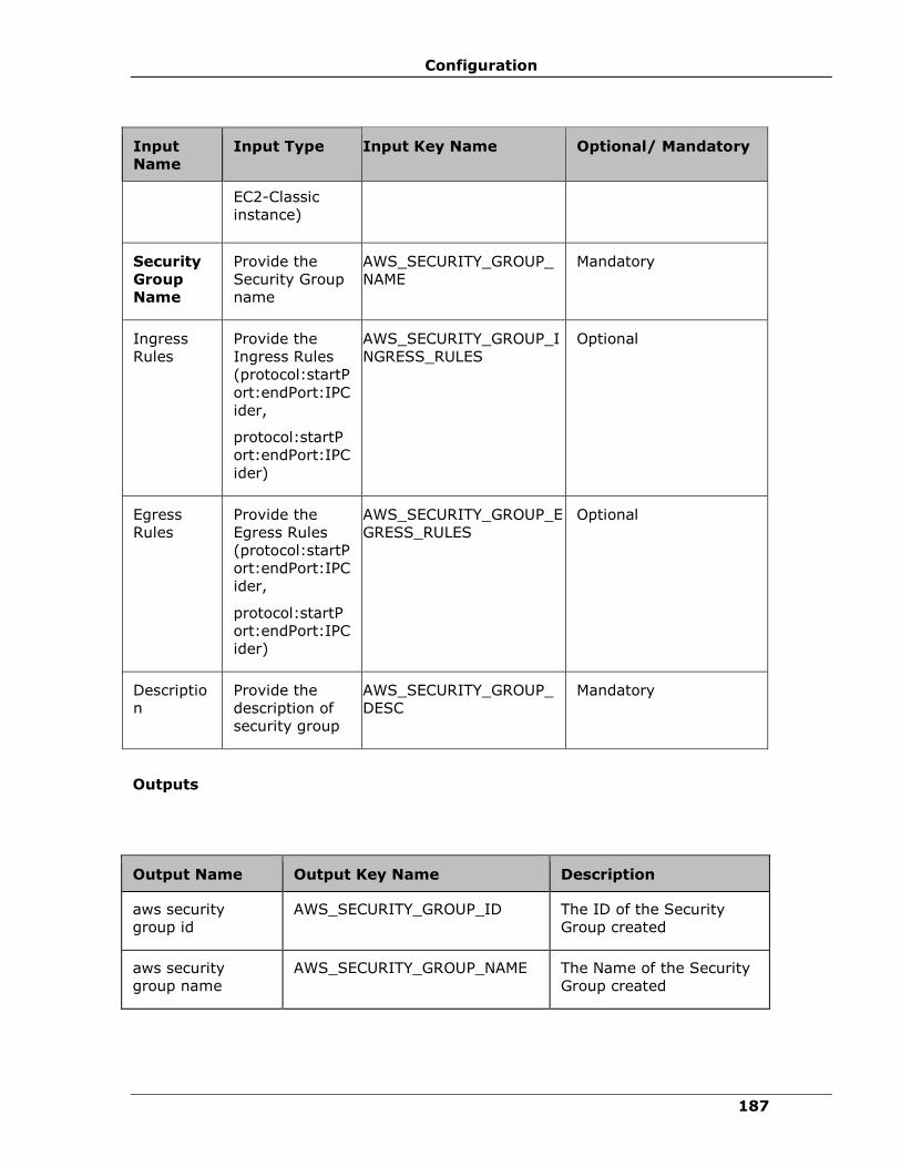
Configuration
187
Input
Name
Input Type Input Key Name Optional/ Mandatory
EC2-Classic
instance)
Security
Group
Name
Provide the
Security Group
name
AWS_SECURITY_GROUP_
NAME
Mandatory
Ingress
Rules
Provide the
Ingress Rules
(protocol:startP
ort:endPort:IPC
ider,
protocol:startP
ort:endPort:IPC
ider)
AWS_SECURITY_GROUP_I
NGRESS_RULES
Optional
Egress
Rules
Provide the
Egress Rules
(protocol:startP
ort:endPort:IPC
ider,
protocol:startP
ort:endPort:IPC
ider)
AWS_SECURITY_GROUP_E
GRESS_RULES
Optional
Descriptio
n
Provide the
description of
security group
AWS_SECURITY_GROUP_
DESC
Mandatory
Outputs
Output Name Output Key Name Description
aws security
group id
AWS_SECURITY_GROUP_ID The ID of the Security
Group created
aws security
group name
AWS_SECURITY_GROUP_NAME The Name of the Security
Group created

IBM Resiliency Orchestration Administrator’s Guide
© IBM Corporation 2017 188
Create Amazon S3 Bucket
Description
This action will creates S3 Bucket in Specified Region.
Inputs
Input Name Input Type Input Key Name Optional/
Mandatory
Management
Service Name
Choose from
List of
Management
Service Name
AWS_MANAGEMENT_SERVICE Mandatory
Bucket Name Bucket Name AWS_BUCKET_NAME Mandatory
Region Choose from
List of Regions
AWS_REGION Mandatory
Outputs
Output Name Output Key Name Description
aws bucket name AWS_BUCKET_NAME Bucket Name
Delete Amazon Volume
Description
This action deletes the volume in AWS.
Inputs
Input Name Input
Type
Input Key Name Optional/
Mandatory
Description
aws volume id String AWS_VOLUME_ID Mandatory Select the
volume id
from the
drop-down
list.
aws management String AWS_MANAGEMENT_SERVICE Mandatory Select the
management
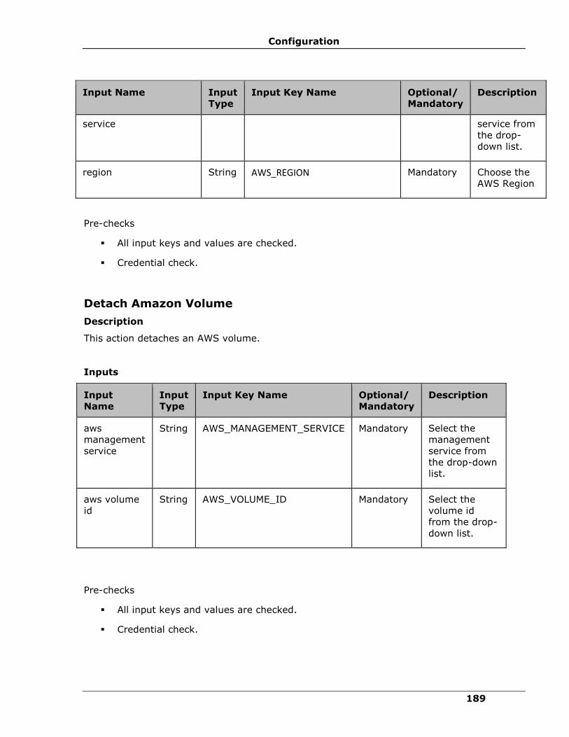
Configuration
189
Input Name Input
Type
Input Key Name Optional/
Mandatory
Description
service service from
the drop-
down list.
region String AWS_REGION Mandatory Choose the
AWS Region
Pre-checks
▪ All input keys and values are checked.
▪ Credential check.
Detach Amazon Volume
Description
This action detaches an AWS volume.
Inputs
Input
Name
Input
Type
Input Key Name Optional/
Mandatory
Description
aws
management
service
String AWS_MANAGEMENT_SERVICE Mandatory Select the
management
service from
the drop-down
list.
aws volume
id
String AWS_VOLUME_ID Mandatory Select the
volume id
from the drop-
down list.
Pre-checks
▪ All input keys and values are checked.
▪ Credential check.

IBM Resiliency Orchestration Administrator’s Guide
© IBM Corporation 2017 190
Delete Amazon Snapshot
Description
This action deletes the Snapshot in the AWS .
Inputs
Input
Name
Input
Type
Input Key Name Optional/
Mandatory
Description
aws
management
service
String AWS_MANAGEMENT_SERVICE Mandatory Select the
management
service from
the drop-
down list.
aws
snapshot id
String AWS_SNAPSHOT_ID Mandatory Select the
snapshot id
from the
drop-down
list.
Pre-checks
▪ All input keys and values are checked.
▪ Credential check.
Import EC2 RAL
Description
This action will import the instance to the AWS instances.
Inputs
Input Name Input Type Input Key Name Optional/
Mandatory
Management Service
Name
Choose from
List of
Management
Service Name
AWS_MANAGEMENT_SE
RVICE Mandatory

Configuration
191
Input Name Input Type Input Key Name Optional/
Mandatory
Region Choose the AWS
Region
AWS_REGION Mandatory
Availability Zone Choose the AWS
Availability Zone
AWS_AVAILABILITY_ZO
NE
Mandatory
Instance Type Choose the
available
instance type
AWS_INSTANCE_TYPE Mandatory
Instance Name Provide instance
name
AWS_INSTANCE_NAME Optional
Architecture Choose the
available
architecture
AWS_INSTANCE_ARCHIT
ECTURE
Mandatory
Platform Choose the
available
platform
AWS_PLATFORM Optional
Subnet Id Choose the
available subnet
or create new
AWS_SUBNET_ID Mandatory
Private IP Provide Private
IP Address
within subnet
AWS_PRIVATE_IP_ADDR
ESS
Optional
Replication appliance Choose the
replication
appliances
where the CBT is
running. Only
OVA replication
appliances can
be listed
AWS_REPLICATION_APP
LIANCE
Mandatory
File format Choose the file
format. As of
now only RAW is
supported
AWS_FILE_FORMAT Mandatory
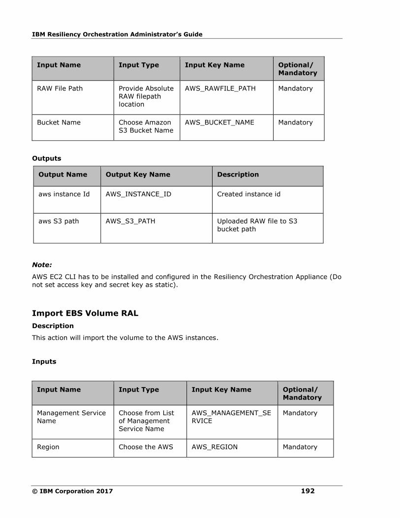
IBM Resiliency Orchestration Administrator’s Guide
© IBM Corporation 2017 192
Input Name Input Type Input Key Name Optional/
Mandatory
RAW File Path Provide Absolute
RAW filepath
location
AWS_RAWFILE_PATH Mandatory
Bucket Name Choose Amazon
S3 Bucket Name
AWS_BUCKET_NAME Mandatory
Outputs
Output Name Output Key Name Description
aws instance Id AWS_INSTANCE_ID Created instance id
aws S3 path AWS_S3_PATH Uploaded RAW file to S3
bucket path
Note:
AWS EC2 CLI has to be installed and configured in the Resiliency Orchestration Appliance (Do
not set access key and secret key as static).
Import EBS Volume RAL
Description
This action will import the volume to the AWS instances.
Inputs
Input Name Input Type Input Key Name Optional/
Mandatory
Management Service
Name
Choose from List
of Management
Service Name
AWS_MANAGEMENT_SE
RVICE
Mandatory
Region Choose the AWS AWS_REGION Mandatory
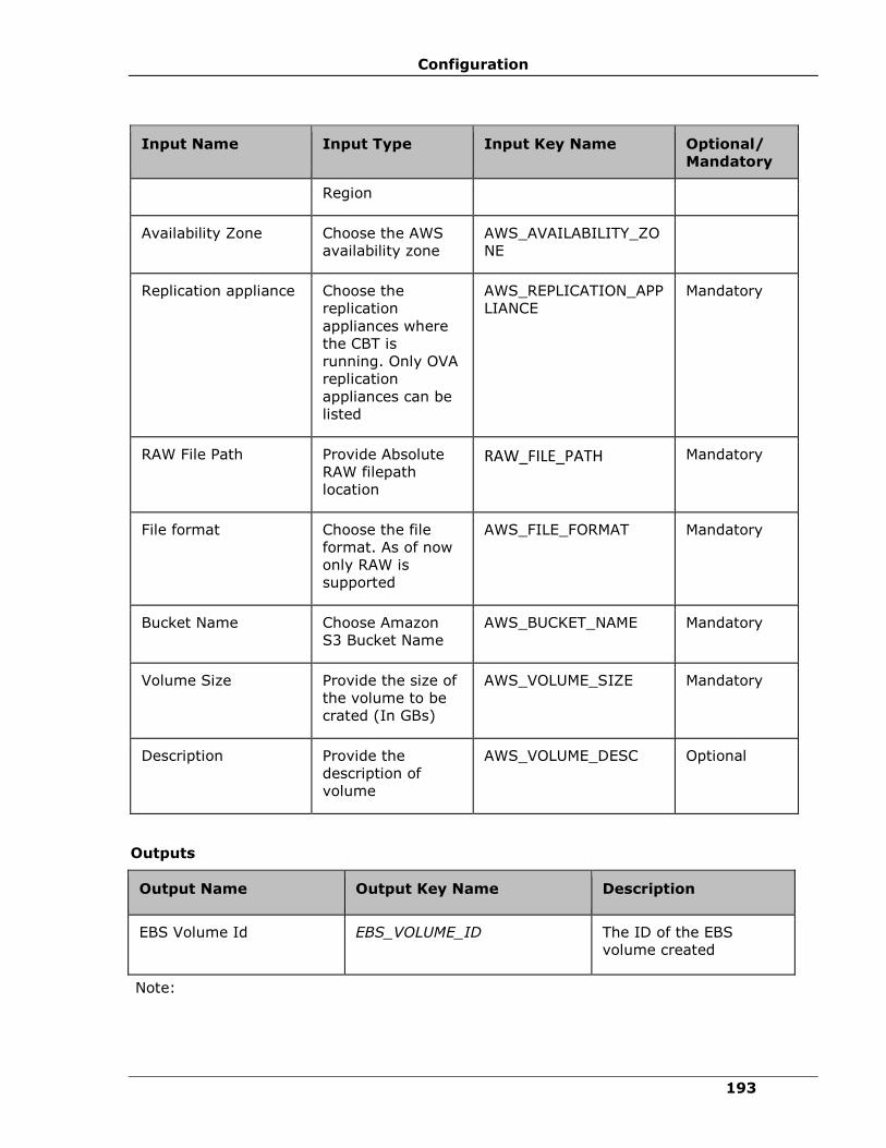
Configuration
193
Input Name Input Type Input Key Name Optional/
Mandatory
Region
Availability Zone Choose the AWS
availability zone
AWS_AVAILABILITY_ZO
NE
Replication appliance Choose the
replication
appliances where
the CBT is
running. Only OVA
replication
appliances can be
listed
AWS_REPLICATION_APP
LIANCE
Mandatory
RAW File Path Provide Absolute
RAW filepath
location
RAW_FILE_PATH Mandatory
File format Choose the file
format. As of now
only RAW is
supported
AWS_FILE_FORMAT Mandatory
Bucket Name Choose Amazon
S3 Bucket Name
AWS_BUCKET_NAME Mandatory
Volume Size Provide the size of
the volume to be
crated (In GBs)
AWS_VOLUME_SIZE Mandatory
Description Provide the
description of
volume
AWS_VOLUME_DESC Optional
Outputs
Output Name Output Key Name Description
EBS Volume Id EBS_VOLUME_ID The ID of the EBS
volume created
Note:

IBM Resiliency Orchestration Administrator’s Guide
© IBM Corporation 2017 194
AWS EC2 CLI has to be installed and configured in the Resiliency Orchestration Appliance
(Do not set access key and secret key as static).
Start AWS Instance
Description
This action starts the instances in AWS.
Input
Name
Input
Type
Input Key Name Optional/
Mandatory
Description
Management
Service
Name
String AWS_MANAGEMENT_SERVICE Mandatory Choose from
List of
Management
Service
Name.
Region String AWS_REGION Mandatory Choose the
AWS
Region.
Instance String AWS_INSTANCE_ID Mandatory Choose the
instance
available on
the selected
region.
Stop Amazon Instance
Description
This action stops the instance in AWS.
Inputs
Input
Name
Input
Type
Input Key Name Optional/
Mandatory
Description
Management
Service
Name
String AWS_MANAGEMENT_SERVICE Mandatory Choose from
List of
Management
Service

Configuration
195
Input
Name
Input
Type
Input Key Name Optional/
Mandatory
Description
Name.
Region String AWS_REGION Mandatory Choose the
AWS
Region.
Instance String AWS_INSTANCE_ID Mandatory Choose the
instance
available on
the selected
region.
S3 Bucket CleanUp
Description
This action will cleans file/folder from Amazon S3 Bucket.
Inputs
Input Name Input Type Input Key Name Optional/
Mandatory
Management
Service Name
Choose from List
of Management
Service Name
AWS_MANAGEMENT_SERVICE Mandatory
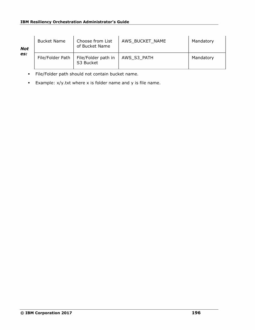
IBM Resiliency Orchestration Administrator’s Guide
© IBM Corporation 2017 196
Not
es:
▪ File/Folder path should not contain bucket name.
▪ Example: x/y.txt where x is folder name and y is file name.
Bucket Name Choose from List
of Bucket Name
AWS_BUCKET_NAME Mandatory
File/Folder Path File/Folder path in
S3 Bucket
AWS_S3_PATH Mandatory

Configuration
197
VMware VCenter
VMware vCenter
These RALs runs on VMware vCenter and executed actions on VMware entities like Virtual
Machines, Data stores, HBAs etc.
Pre-requisites for VMware VCenter RALs
1. Configure Windows Server where VCenter Service is running as Component.
2. Configure VCenter Server as Dataset with above as Component giving Credentials
required to Login into VSphere client with Admin privileges.
3. To execute these RALs, one group should have been created using above step as
component.
4. Make sure VMware vCenter Agent is up and running on Admin page.
Add VMDK to Virtual Machine
Description
This action adds disk to Virtual Machine.
Inputs
Input Name Input Type Optional/
Mandatory
Description
VMware VC
Dataset
String Mandatory Select the dataset from the
dropdown list.
Virtual
Machine(VM)
Name
String Mandatory Input the VM name.
VMDK File
Path
String Mandatory Input the path of VDMK file with
data store.
Mode
(Persistent,
Independent-
persistent,
Independent-
nonpersistent)
String Mandatory Input the mode of the VM.
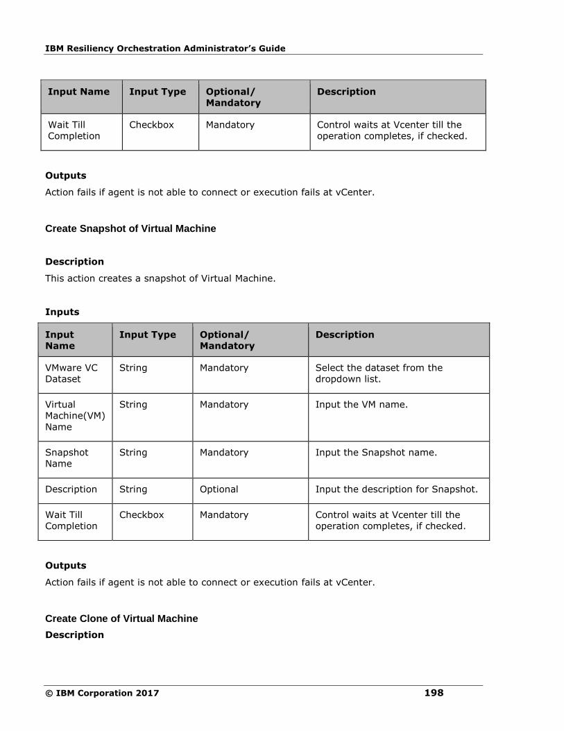
IBM Resiliency Orchestration Administrator’s Guide
© IBM Corporation 2017 198
Input Name Input Type Optional/
Mandatory
Description
Wait Till
Completion
Checkbox Mandatory Control waits at Vcenter till the
operation completes, if checked.
Outputs
Action fails if agent is not able to connect or execution fails at vCenter.
Create Snapshot of Virtual Machine
Description
This action creates a snapshot of Virtual Machine.
Inputs
Input
Name
Input Type Optional/
Mandatory
Description
VMware VC
Dataset
String Mandatory Select the dataset from the
dropdown list.
Virtual
Machine(VM)
Name
String Mandatory Input the VM name.
Snapshot
Name
String Mandatory Input the Snapshot name.
Description String Optional Input the description for Snapshot.
Wait Till
Completion
Checkbox Mandatory Control waits at Vcenter till the
operation completes, if checked.
Outputs
Action fails if agent is not able to connect or execution fails at vCenter.
Create Clone of Virtual Machine
Description

Configuration
199
This action creates a clone of Virtual Machine.
Inputs
Input
Name
Input Type Optional/
Mandatory
Description
VMware
VC Dataset
String Mandatory Select the dataset from the dropdown
list.
Datacenter
Name
String Mandatory Input the name of datacenter.
Source VM
Path
String Mandatory Inventory Path of VM in the form of
Datacenter_Name\VMFolder\VM_Name.
Clone
Name
String Mandatory Input the name of the clone.
Wait Till
Completion
Checkbox Mandatory Control waits at Vcenter till the
operation completes, if checked.
Outputs
Action fails if agent is not able to connect or execution fails at vCenter.
Delete Snapshot of Virtual Machine
Description
This action deletes a snapshot of Virtual Machine.
Inputs
Input
Name
Input Type Optional/
Mandatory
Description
VMware VC
Dataset
String Mandatory Select the dataset from the
dropdown list.
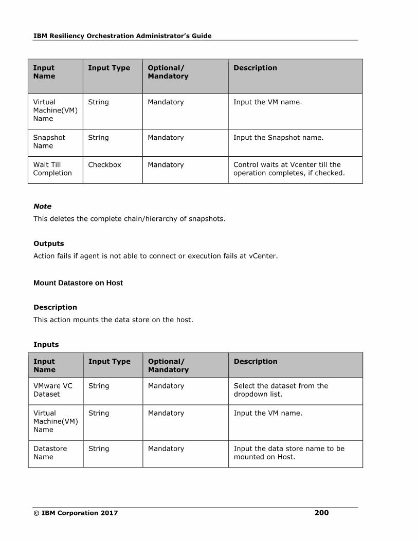
IBM Resiliency Orchestration Administrator’s Guide
© IBM Corporation 2017 200
Input
Name
Input Type Optional/
Mandatory
Description
Virtual
Machine(VM)
Name
String Mandatory Input the VM name.
Snapshot
Name
String Mandatory Input the Snapshot name.
Wait Till
Completion Checkbox Mandatory Control waits at Vcenter till the
operation completes, if checked.
Note
This deletes the complete chain/hierarchy of snapshots.
Outputs
Action fails if agent is not able to connect or execution fails at vCenter.
Mount Datastore on Host
Description
This action mounts the data store on the host.
Inputs
Input
Name
Input Type Optional/
Mandatory
Description
VMware VC
Dataset
String Mandatory Select the dataset from the
dropdown list.
Virtual
Machine(VM)
Name
String Mandatory Input the VM name.
Datastore
Name
String Mandatory Input the data store name to be
mounted on Host.
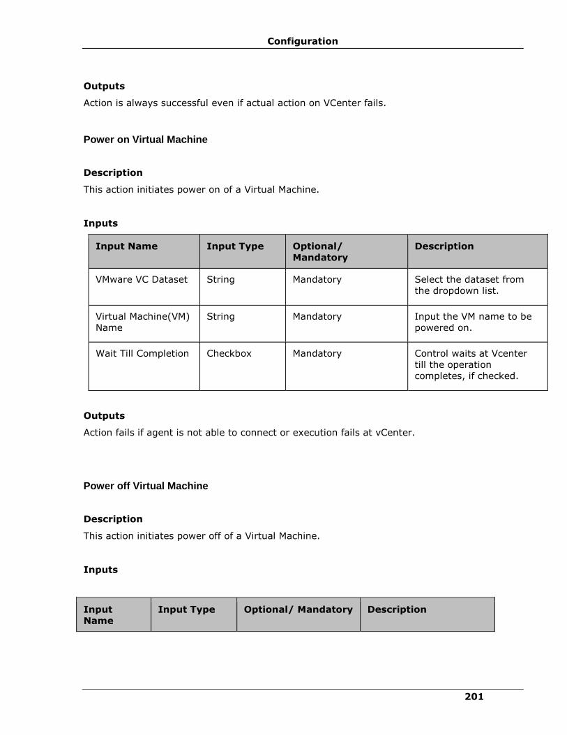
Configuration
201
Outputs
Action is always successful even if actual action on VCenter fails.
Power on Virtual Machine
Description
This action initiates power on of a Virtual Machine.
Inputs
Input Name Input Type Optional/
Mandatory
Description
VMware VC Dataset String Mandatory Select the dataset from
the dropdown list.
Virtual Machine(VM)
Name
String Mandatory Input the VM name to be
powered on.
Wait Till Completion Checkbox Mandatory Control waits at Vcenter
till the operation
completes, if checked.
Outputs
Action fails if agent is not able to connect or execution fails at vCenter.
Power off Virtual Machine
Description
This action initiates power off of a Virtual Machine.
Inputs
Input
Name
Input Type Optional/ Mandatory Description

IBM Resiliency Orchestration Administrator’s Guide
© IBM Corporation 2017 202
Input
Name
Input Type Optional/ Mandatory Description
VMware VC
Dataset
String Mandatory Select the dataset from
the dropdown list.
Virtual
Machine(VM)
Name
String Mandatory Input the VM name to be
powered off.
Wait Till
Completion
Checkbox Mandatory Control waits at Vcenter
till the operation
completes, if checked.
Outputs
Action fails if agent is not able to connect or execution fails at vCenter.
Reboot Virtual Machine
Description
This action reboots a Virtual Machine.
Inputs
Input
Name
Input Type Optional/ Mandatory Description
VMware VC
Dataset
String Mandatory Select the dataset from
the dropdown list.
Virtual
Machine(VM)
Name
String Mandatory Input the VM name to be
rebooted.
Outputs
Action fails if agent is not able to connect or execution fails at vCenter.
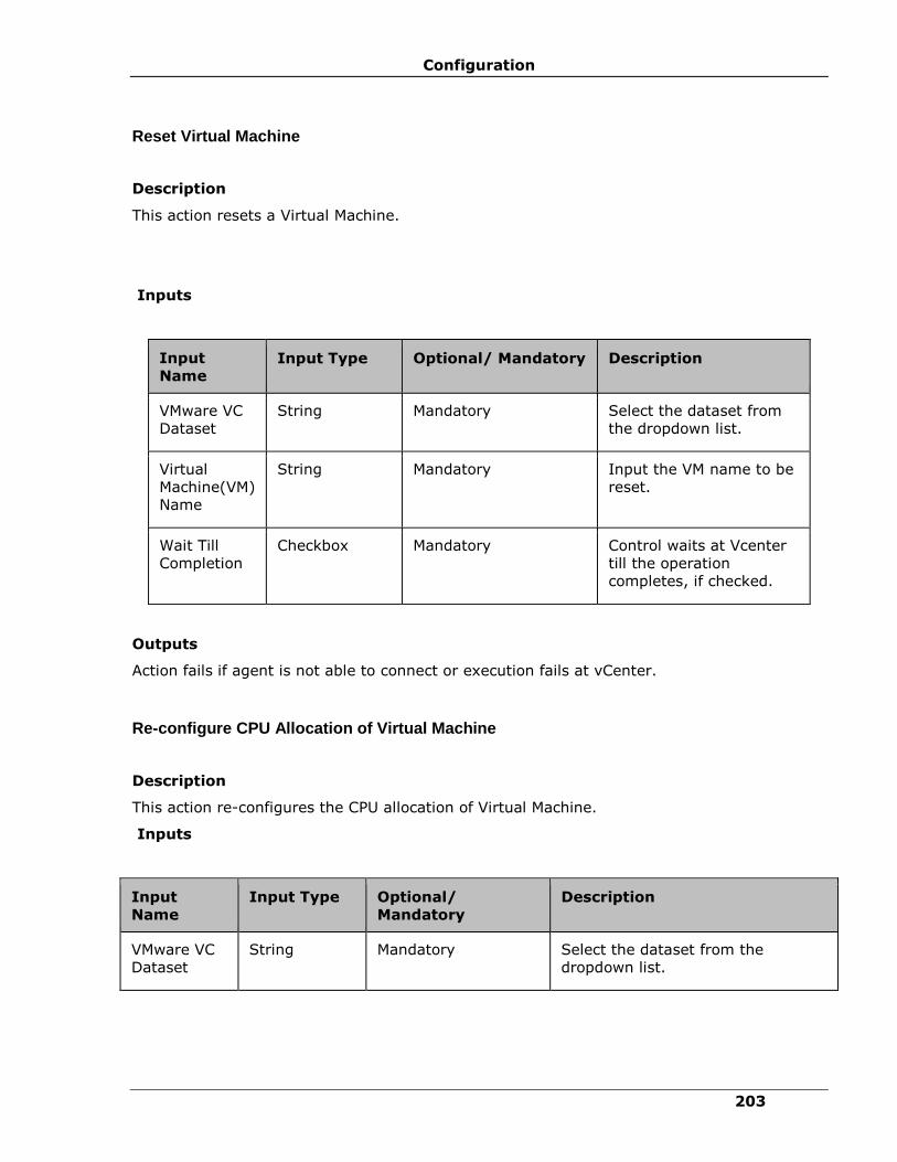
Configuration
203
Reset Virtual Machine
Description
This action resets a Virtual Machine.
Inputs
Input
Name Input Type Optional/ Mandatory Description
VMware VC
Dataset
String Mandatory Select the dataset from
the dropdown list.
Virtual
Machine(VM)
Name
String Mandatory Input the VM name to be
reset.
Wait Till
Completion
Checkbox Mandatory Control waits at Vcenter
till the operation
completes, if checked.
Outputs
Action fails if agent is not able to connect or execution fails at vCenter.
Re-configure CPU Allocation of Virtual Machine
Description
This action re-configures the CPU allocation of Virtual Machine.
Inputs
Input
Name
Input Type Optional/
Mandatory
Description
VMware VC
Dataset
String Mandatory Select the dataset from the
dropdown list.
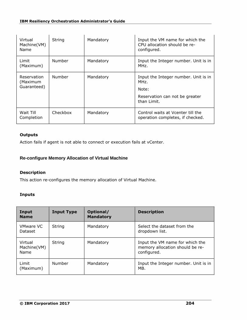
IBM Resiliency Orchestration Administrator’s Guide
© IBM Corporation 2017 204
Virtual
Machine(VM)
Name
String Mandatory Input the VM name for which the
CPU allocation should be re-
configured.
Limit
(Maximum)
Number Mandatory Input the Integer number. Unit is in
MHz.
Reservation
(Maximum
Guaranteed)
Number Mandatory Input the Integer number. Unit is in
MHz.
Note:
Reservation can not be greater
than Limit.
Wait Till
Completion Checkbox Mandatory Control waits at Vcenter till the
operation completes, if checked.
Outputs
Action fails if agent is not able to connect or execution fails at vCenter.
Re-configure Memory Allocation of Virtual Machine
Description
This action re-configures the memory allocation of Virtual Machine.
Inputs
Input
Name
Input Type Optional/
Mandatory
Description
VMware VC
Dataset
String Mandatory Select the dataset from the
dropdown list.
Virtual
Machine(VM)
Name
String Mandatory Input the VM name for which the
memory allocation should be re-
configured.
Limit
(Maximum)
Number Mandatory Input the Integer number. Unit is in
MB.
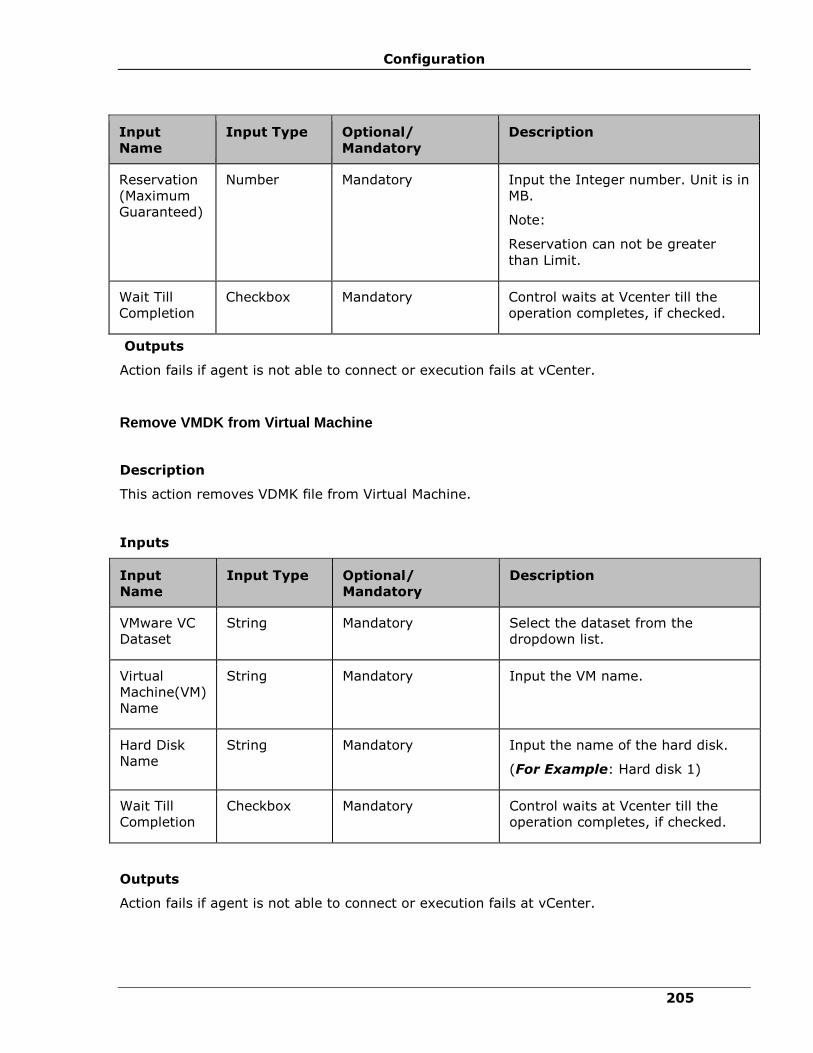
Configuration
205
Input
Name
Input Type Optional/
Mandatory
Description
Reservation
(Maximum
Guaranteed)
Number Mandatory Input the Integer number. Unit is in
MB.
Note:
Reservation can not be greater
than Limit.
Wait Till
Completion
Checkbox Mandatory Control waits at Vcenter till the
operation completes, if checked.
Outputs
Action fails if agent is not able to connect or execution fails at vCenter.
Remove VMDK from Virtual Machine
Description
This action removes VDMK file from Virtual Machine.
Inputs
Input
Name
Input Type Optional/
Mandatory
Description
VMware VC
Dataset
String Mandatory Select the dataset from the
dropdown list.
Virtual
Machine(VM)
Name
String Mandatory Input the VM name.
Hard Disk
Name
String Mandatory Input the name of the hard disk.
(For Example: Hard disk 1)
Wait Till
Completion
Checkbox Mandatory Control waits at Vcenter till the
operation completes, if checked.
Outputs
Action fails if agent is not able to connect or execution fails at vCenter.
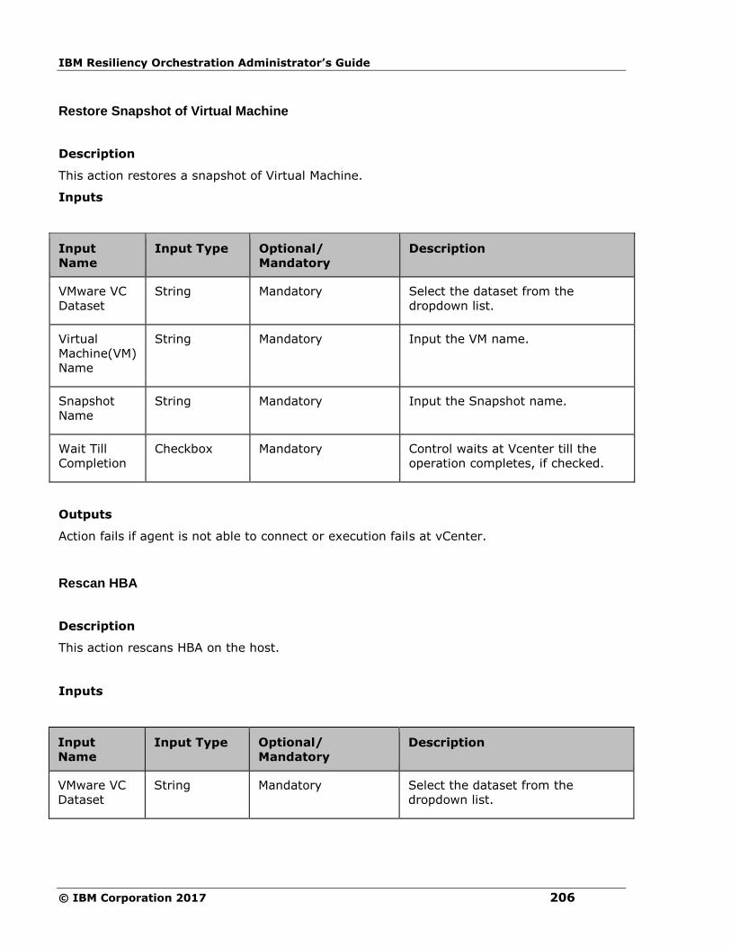
IBM Resiliency Orchestration Administrator’s Guide
© IBM Corporation 2017 206
Restore Snapshot of Virtual Machine
Description
This action restores a snapshot of Virtual Machine.
Inputs
Input
Name
Input Type Optional/
Mandatory
Description
VMware VC
Dataset
String Mandatory Select the dataset from the
dropdown list.
Virtual
Machine(VM)
Name
String Mandatory Input the VM name.
Snapshot
Name
String Mandatory Input the Snapshot name.
Wait Till
Completion
Checkbox Mandatory Control waits at Vcenter till the
operation completes, if checked.
Outputs
Action fails if agent is not able to connect or execution fails at vCenter.
Rescan HBA
Description
This action rescans HBA on the host.
Inputs
Input
Name Input Type Optional/
Mandatory Description
VMware VC
Dataset
String Mandatory Select the dataset from the
dropdown list.
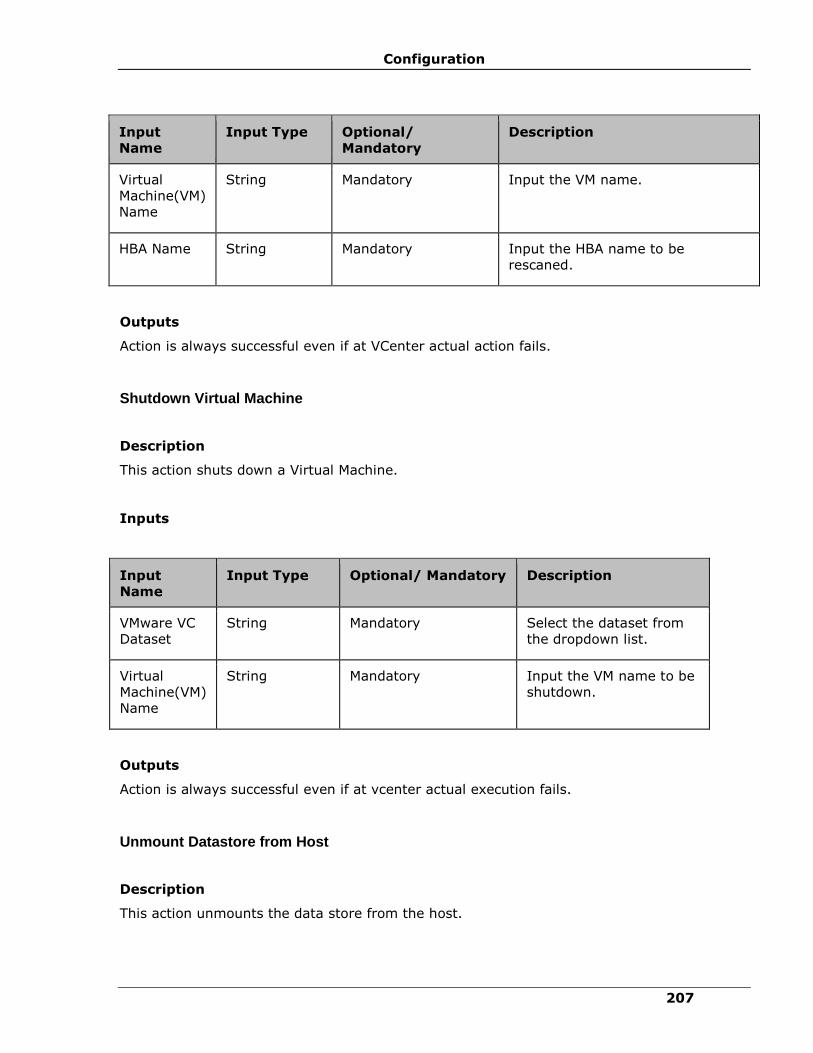
Configuration
207
Input
Name
Input Type Optional/
Mandatory
Description
Virtual
Machine(VM)
Name
String Mandatory Input the VM name.
HBA Name String Mandatory Input the HBA name to be
rescaned.
Outputs
Action is always successful even if at VCenter actual action fails.
Shutdown Virtual Machine
Description
This action shuts down a Virtual Machine.
Inputs
Input
Name
Input Type Optional/ Mandatory Description
VMware VC
Dataset
String Mandatory Select the dataset from
the dropdown list.
Virtual
Machine(VM)
Name
String Mandatory Input the VM name to be
shutdown.
Outputs
Action is always successful even if at vcenter actual execution fails.
Unmount Datastore from Host
Description
This action unmounts the data store from the host.

IBM Resiliency Orchestration Administrator’s Guide
© IBM Corporation 2017 208
Inputs
Input
Name
Input Type Optional/
Mandatory
Description
VMware VC
Dataset
String Mandatory Select the dataset from the
dropdown list.
Virtual
Machine(VM)
Name
String Mandatory Input the VM name.
Datastore
Name
String Mandatory Input the data store name to be
unmounted from the host.
Outputs
Action is always successful even if actual action on VCenter fails.
Add Virtual Machine to Inventory
Description
This action adds Virtual Machine (VM) to the inventory.
Inputs
The following is a list of inputs that are required to perform this action.
Input
Name
Input
Type
Key Name Optional/
Mandatory
Description
VCenter
Management
Service
String PANVC_MGMT_SVC_NAME Mandatory Select the
VCenter
Management
service.
Datacenter
Name
String PANVC_DC_NAME Mandatory Select the
Datacenter
name.
ESX Host
Name
String PANVC_VM_HOST_NAME Mandatory Select the
ESX host IP.
Resource String PANVC_RESOURCE_POOL_NAME Optional Select the
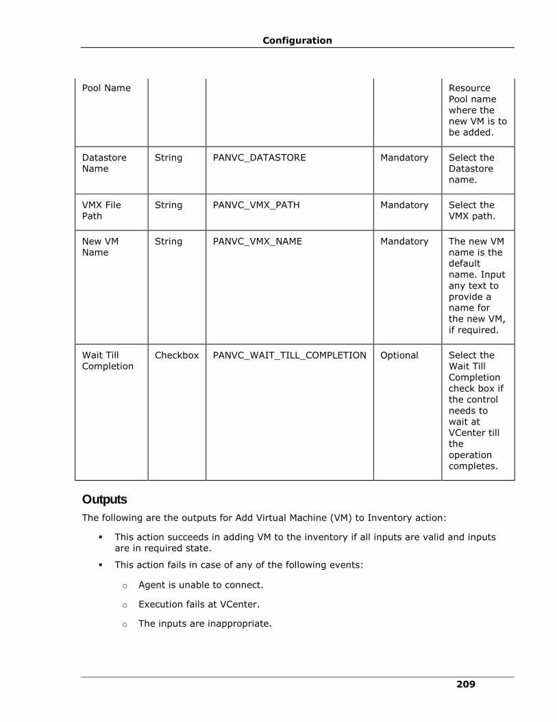
Configuration
209
Pool Name Resource
Pool name
where the
new VM is to
be added.
Datastore
Name
String PANVC_DATASTORE Mandatory Select the
Datastore
name.
VMX File
Path
String PANVC_VMX_PATH Mandatory Select the
VMX path.
New VM
Name
String
PANVC_VMX_NAME
Mandatory The new VM
name is the
default
name. Input
any text to
provide a
name for
the new VM,
if required.
Wait Till
Completion Checkbox PANVC_WAIT_TILL_COMPLETION Optional Select the
Wait Till
Completion
check box if
the control
needs to
wait at
VCenter till
the
operation
completes.
Outputs
The following are the outputs for Add Virtual Machine (VM) to Inventory action:
▪ This action succeeds in adding VM to the inventory if all inputs are valid and inputs
are in required state.
▪ This action fails in case of any of the following events:
o Agent is unable to connect.
o Execution fails at VCenter.
o The inputs are inappropriate.
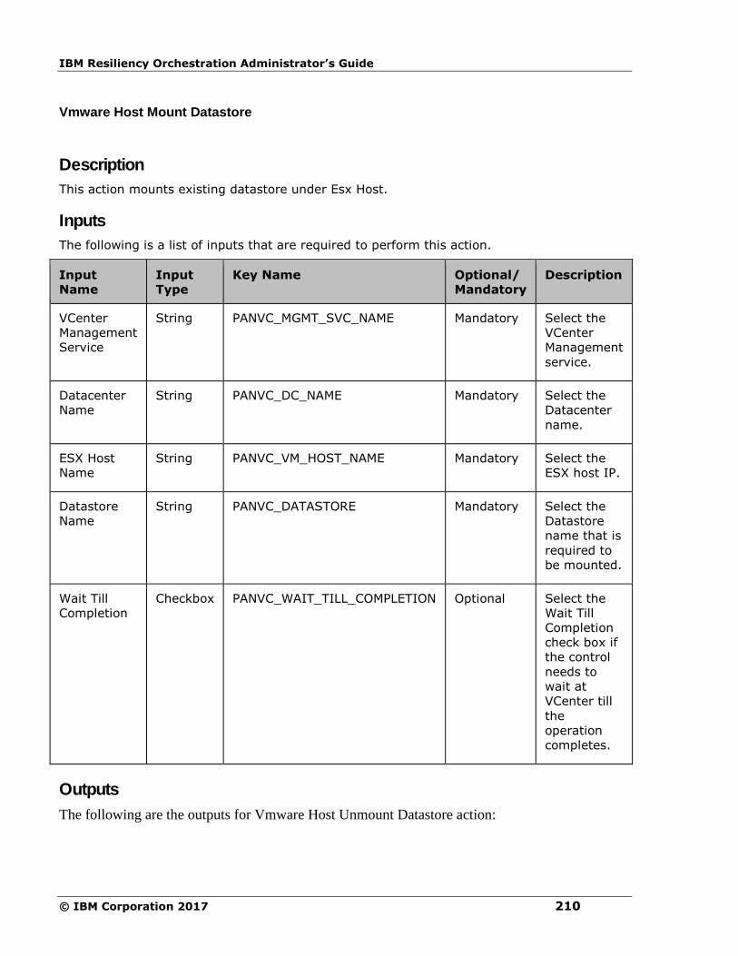
IBM Resiliency Orchestration Administrator’s Guide
© IBM Corporation 2017 210
Vmware Host Mount Datastore
Description
This action mounts existing datastore under Esx Host.
Inputs
The following is a list of inputs that are required to perform this action.
Input
Name
Input
Type
Key Name Optional/
Mandatory
Description
VCenter
Management
Service
String PANVC_MGMT_SVC_NAME Mandatory Select the
VCenter
Management
service.
Datacenter
Name
String PANVC_DC_NAME Mandatory Select the
Datacenter
name.
ESX Host
Name
String PANVC_VM_HOST_NAME Mandatory Select the
ESX host IP.
Datastore
Name
String
PANVC_DATASTORE Mandatory Select the
Datastore
name that is
required to
be mounted.
Wait Till
Completion
Checkbox PANVC_WAIT_TILL_COMPLETION Optional Select the
Wait Till
Completion
check box if
the control
needs to
wait at
VCenter till
the
operation
completes.
Outputs
The following are the outputs for Vmware Host Unmount Datastore action:
Configuration
211
▪ This action succeeds in unmounting the datastore if the datastore is valid and in mounted
state.
▪ This action fails in case of any of the following events:
o Agent is unable to connect,
o Execution fails at VCenter.
o Datastore is invalid.
o Datastore is in unmounted state.

IBM Resiliency Orchestration Administrator’s Guide
© IBM Corporation 2017 212
Vmware Host Unmount Datastore
Description
This action unmounts existing datastore under Esx host.
Inputs
The following is a list of inputs that are required to perform this action.
Input
Name
Input
Type
Key Name Optional/
Mandatory
Description
VCenter
Management
Service
String PANVC_MGMT_SVC_NAME Mandatory Select the
VCenter
Management
Service.
Datacenter
Name String PANVC_DC_NAME Mandatory Select the
Datacenter
name.
ESX Host
Name String PANVC_VM_HOST_NAME Mandatory Select the
ESX host IP.
Datastore
Name
String PANVC_DATASTORE Mandatory Select the
Datastore
name.
Wait Till
Completion
Checkbox PANVC_WAIT_TILL_COMPLETION Optional Select the
Wait Till
Completion
check box if
the control
needs to
wait at
VCenter till
the
operation
completes.
Outputs
The following are the outputs for the Vmware Host Unmount Datastore action:
▪ This action succeeds in unmounting the datastore if the datastore is valid and in mounted
state.

Configuration
213
▪ This action fails in case of any of the following events:
o Agent is unable to connect
o Execution fails at VCenter
o Datastore is invalid
o Datastore is in unmounted state
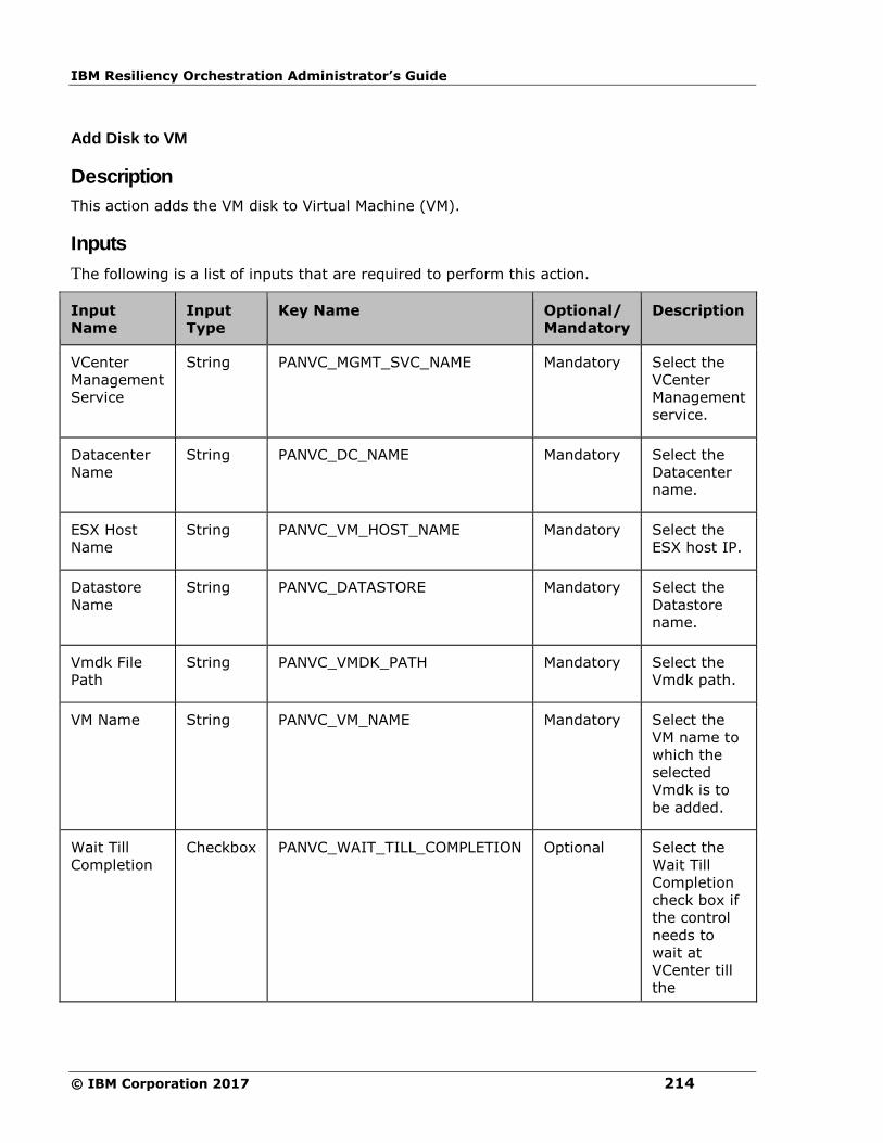
IBM Resiliency Orchestration Administrator’s Guide
© IBM Corporation 2017 214
Add Disk to VM
Description
This action adds the VM disk to Virtual Machine (VM).
Inputs
The following is a list of inputs that are required to perform this action.
Input
Name
Input
Type
Key Name Optional/
Mandatory
Description
VCenter
Management
Service
String PANVC_MGMT_SVC_NAME Mandatory Select the
VCenter
Management
service.
Datacenter
Name
String PANVC_DC_NAME Mandatory Select the
Datacenter
name.
ESX Host
Name
String PANVC_VM_HOST_NAME Mandatory Select the
ESX host IP.
Datastore
Name
String PANVC_DATASTORE Mandatory Select the
Datastore
name.
Vmdk File
Path
String PANVC_VMDK_PATH Mandatory Select the
Vmdk path.
VM Name String PANVC_VM_NAME Mandatory Select the
VM name to
which the
selected
Vmdk is to
be added.
Wait Till
Completion
Checkbox PANVC_WAIT_TILL_COMPLETION Optional Select the
Wait Till
Completion
check box if
the control
needs to
wait at
VCenter till
the

Configuration
215
operation
completes.
Outputs
The following are the outputs for the Add Disk to VM action:
▪ This action succeeds adding Vmdk to VM if all inputs are valid and inputs are in
required state.
▪ This action fails in case of any of the following events:
2. Agent is unable to connect
3. Execution fails at VCenter
4. The inputs are inappropriate
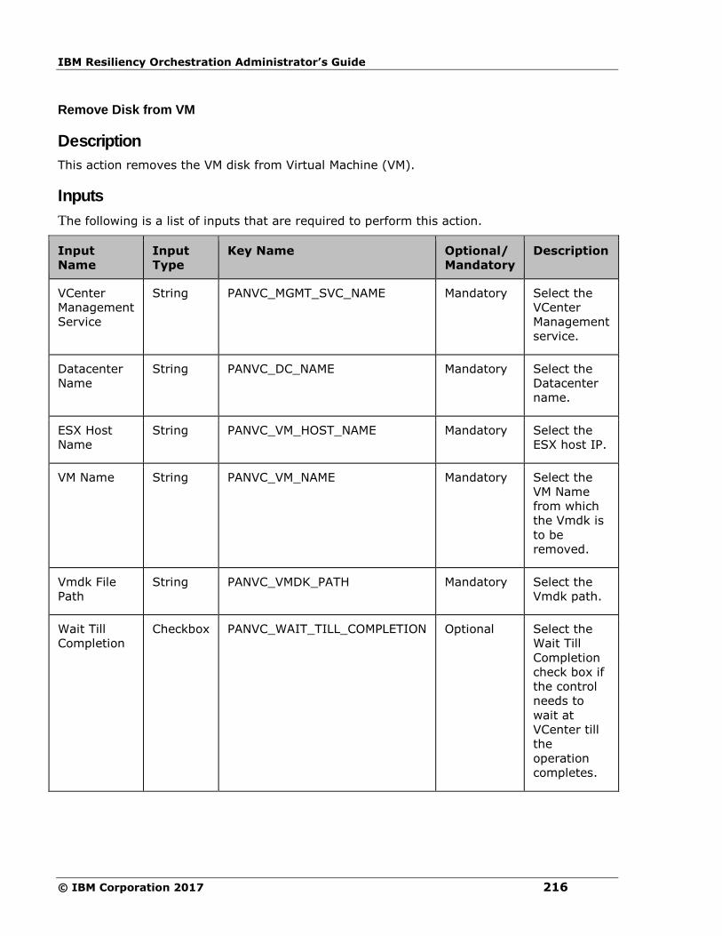
IBM Resiliency Orchestration Administrator’s Guide
© IBM Corporation 2017 216
Remove Disk from VM
Description
This action removes the VM disk from Virtual Machine (VM).
Inputs
The following is a list of inputs that are required to perform this action.
Input
Name
Input
Type
Key Name Optional/
Mandatory
Description
VCenter
Management
Service
String PANVC_MGMT_SVC_NAME Mandatory Select the
VCenter
Management
service.
Datacenter
Name
String PANVC_DC_NAME Mandatory Select the
Datacenter
name.
ESX Host
Name
String PANVC_VM_HOST_NAME Mandatory Select the
ESX host IP.
VM Name String PANVC_VM_NAME Mandatory Select the
VM Name
from which
the Vmdk is
to be
removed.
Vmdk File
Path
String PANVC_VMDK_PATH Mandatory Select the
Vmdk path.
Wait Till
Completion
Checkbox PANVC_WAIT_TILL_COMPLETION Optional Select the
Wait Till
Completion
check box if
the control
needs to
wait at
VCenter till
the
operation
completes.
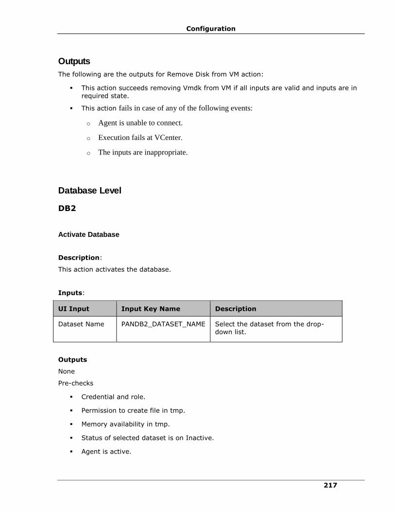
Configuration
217
Outputs
The following are the outputs for Remove Disk from VM action:
▪ This action succeeds removing Vmdk from VM if all inputs are valid and inputs are in
required state.
▪ This action fails in case of any of the following events:
o Agent is unable to connect.
o Execution fails at VCenter.
o The inputs are inappropriate.
Database Level
DB2
Activate Database
Description:
This action activates the database.
Inputs:
UI Input Input Key Name Description
Dataset Name PANDB2_DATASET_NAME Select the dataset from the drop-
down list.
Outputs
None
Pre-checks
▪ Credential and role.
▪ Permission to create file in tmp.
▪ Memory availability in tmp.
▪ Status of selected dataset is on Inactive.
▪ Agent is active.
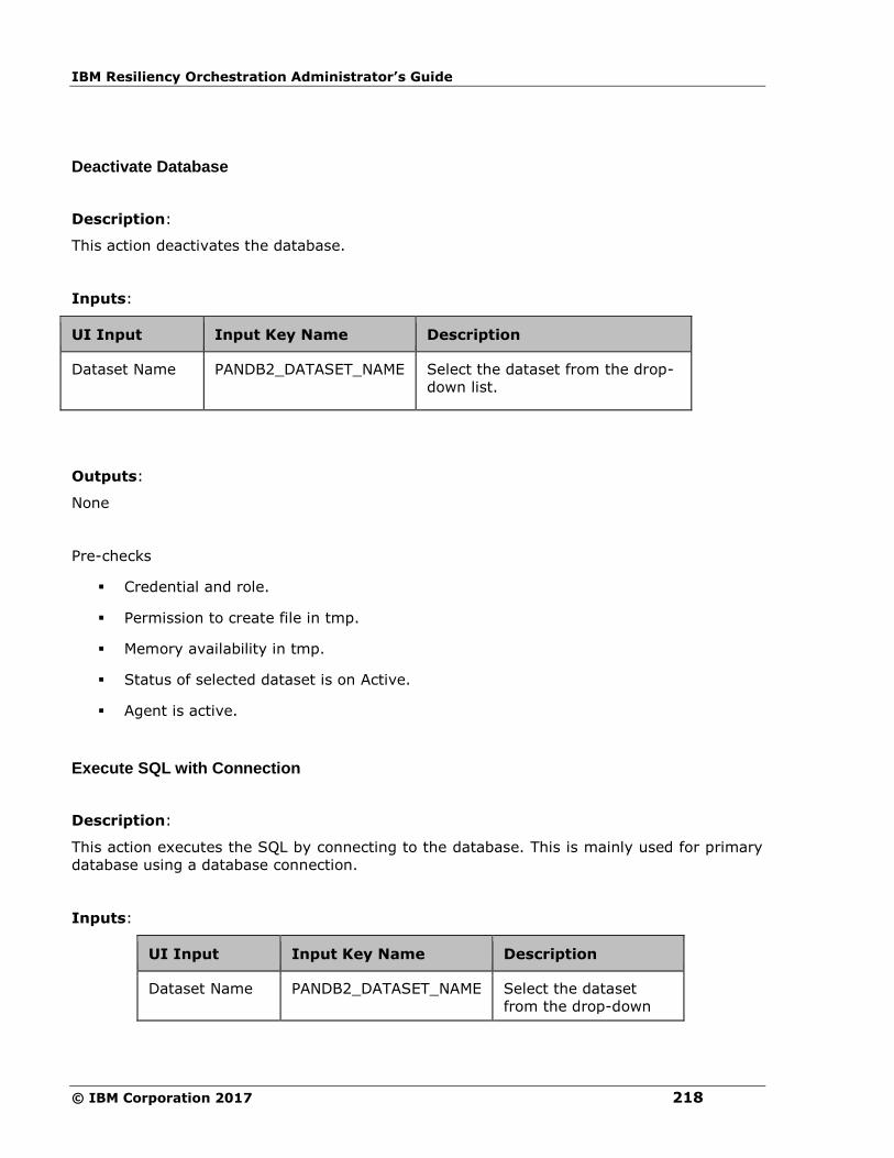
IBM Resiliency Orchestration Administrator’s Guide
© IBM Corporation 2017 218
Deactivate Database
Description:
This action deactivates the database.
Inputs:
UI Input Input Key Name Description
Dataset Name PANDB2_DATASET_NAME Select the dataset from the drop-
down list.
Outputs:
None
Pre-checks
▪ Credential and role.
▪ Permission to create file in tmp.
▪ Memory availability in tmp.
▪ Status of selected dataset is on Active.
▪ Agent is active.
Execute SQL with Connection
Description:
This action executes the SQL by connecting to the database. This is mainly used for primary
database using a database connection.
Inputs:
UI Input Input Key Name Description
Dataset Name PANDB2_DATASET_NAME Select the dataset
from the drop-down

Configuration
219
list.
SQL to be
executed
PANDB2_CONN_SQL Enter the SQL
command to execute.
Outputs:
The action fails, if the database is not in the said state.
Output Name Output Key Name Description
Output of the
SQL
PANDB2_CONN_SQL_RESULT Output of the SQL
that is being
executed.
Pre-checks
▪ Credential and role.
▪ Permission to create file in tmp.
▪ Memory availability in tmp.
▪ Agent is active.
Execute SQL Without Connection
Description:
This action executes the SQL without connecting to the database. This is mainly used for
ADMIN SQL for standby database.
Inputs:
UI Input Input Key Name Description
Dataset Name PANDB2_DATASET_NAME
Select the dataset
from the drop-down
list.
SQL to be
executed
PANDB2_NOCONN_SQL Enter the SQL
command to
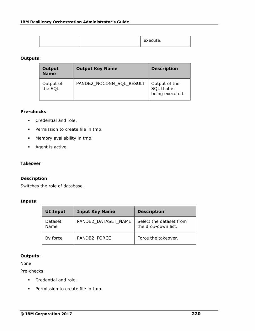
IBM Resiliency Orchestration Administrator’s Guide
© IBM Corporation 2017 220
execute.
Outputs:
Output
Name
Output Key Name Description
Output of
the SQL
PANDB2_NOCONN_SQL_RESULT Output of the
SQL that is
being executed.
Pre-checks
▪ Credential and role.
▪ Permission to create file in tmp.
▪ Memory availability in tmp.
▪ Agent is active.
Takeover
Description:
Switches the role of database.
Inputs:
UI Input Input Key Name Description
Dataset
Name
PANDB2_DATASET_NAME Select the dataset from
the drop-down list.
By force PANDB2_FORCE Force the takeover.
Outputs:
None
Pre-checks
▪ Credential and role.
▪ Permission to create file in tmp.

Configuration
221
▪ Memory availability in tmp.
▪ Status of selected dataset is on Standby.
▪ Agent is active.
Verify Database State
Description:
This action verifies whether the database is ACTIVE, INACTIVE or UNKNOWN.
Inputs:
UI Input Input Key Name Description
Dataset Name PANDB2_DATASET_NAME Select the dataset from
the drop-down list.
Expected State PANDB2_DATASET_STATE The Expected states of
database can be
ACTIVE, INACTIVE or
UNKNOWN.
Outputs:
The action fails, if the database is not in the said state.
Output
Name
Output Key Name Description
Dataset
State
PANDB2_CURRENT_DATASET_STATE The current states of database
(ACTIVE/INACTIVE/UNKNOWN)
Pre-checks
▪ Credential and role.
▪ Permission to create file in tmp.
▪ Memory availability in tmp.
▪ Agent is active.

IBM Resiliency Orchestration Administrator’s Guide
© IBM Corporation 2017 222
DB2VerifyInstanceState
Description:
Verifies the state of the DB2 instance.
Inputs:
UI Input Input Key Name Description
Dataset
Name
PANDB2_DATASET_NAME Select the dataset from
the drop-down list.
Outputs:
The provides the DB2 instance state.
Pre-checks
▪ Credential and role.
▪ Agent is active.
DB2InstanceStateOperation
Description:
Performs the Start/ Stop/ Restart and Forcestop on the DB2 instance.
Inputs:
UI Input Input Key Name Description
Dataset
Name
PANDB2_DATASET_NAME Select the
dataset from
the drop-down
list.
Select
DB2
Instance
Operation
PANDB2_DATASET_INSTANCE_STATE Select Start/
Stop/ Restart
and Forcestop
from the drop-
down list.
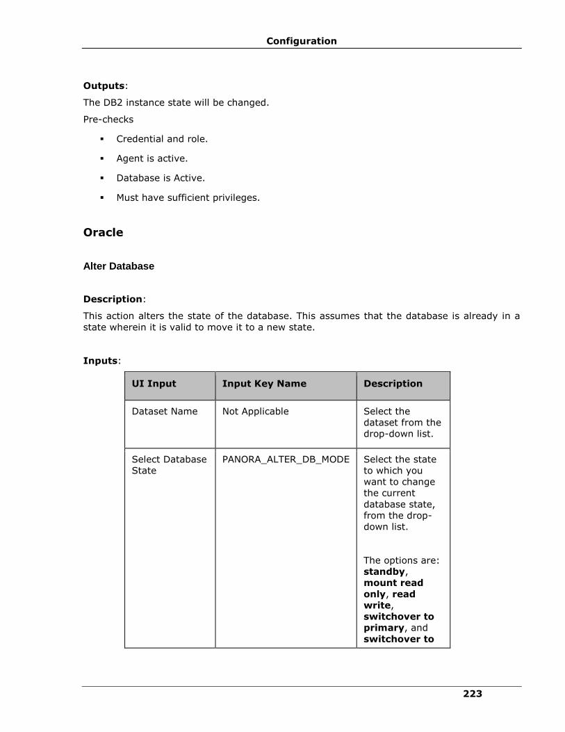
Configuration
223
Outputs:
The DB2 instance state will be changed.
Pre-checks
▪ Credential and role.
▪ Agent is active.
▪ Database is Active.
▪ Must have sufficient privileges.
Oracle
Alter Database
Description:
This action alters the state of the database. This assumes that the database is already in a
state wherein it is valid to move it to a new state.
Inputs:
UI Input Input Key Name Description
Dataset Name Not Applicable Select the
dataset from the
drop-down list.
Select Database
State
PANORA_ALTER_DB_MODE Select the state
to which you
want to change
the current
database state,
from the drop-
down list.
The options are:
standby,
mount read
only, read
write,
switchover to
primary, and
switchover to
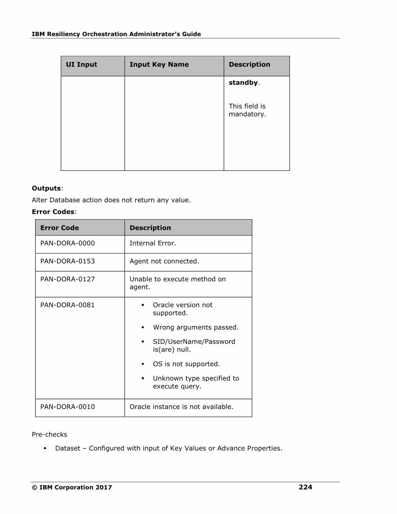
IBM Resiliency Orchestration Administrator’s Guide
© IBM Corporation 2017 224
UI Input Input Key Name Description
standby.
This field is
mandatory.
Outputs:
Alter Database action does not return any value.
Error Codes:
Error Code Description
PAN-DORA-0000 Internal Error.
PAN-DORA-0153 Agent not connected.
PAN-DORA-0127 Unable to execute method on
agent.
PAN-DORA-0081 ▪ Oracle version not
supported.
▪ Wrong arguments passed.
▪ SID/UserName/Password
is(are) null.
▪ OS is not supported.
▪ Unknown type specified to
execute query.
PAN-DORA-0010 Oracle instance is not available.
Pre-checks
▪ Dataset – Configured with input of Key Values or Advance Properties.

Configuration
225
▪ Authentication for the Operating System and Database.
▪ Selected dataset is active.
▪ Privileges before executing any command.
▪ If database is in standby state, then it should be in read/write mode.
▪ If database is in read/write, then it should be in mounted read.
▪ If database is in switchover to primary state, then Production should be in read/write
mode and DR on mounted mode.
▪ If database is in switchover to standby state, then Production should be in mounted
mode and DR on read/write mode.
Apply Logs
Description:
This action recovers/applies the available archived logs which are not applied on the
database. This assumes that the archive logs are already copied/available in the right
location.
Inputs:
UI Input Input Key Name Description
Dataset Name Not Applicable
Select the dataset from the
drop-down list.
Apply Log Delay PANORA_APPLY_LOG_DELAY Enter the log delay time in
minutes.
Default value for this field
is zero.
This field is mandatory.
Outputs:
Output Name Output Key Name Description
Applied
Sequence
PANORA_APPLY_LOG_SEQ_NUM Sequence number of
the last log which got

IBM Resiliency Orchestration Administrator’s Guide
© IBM Corporation 2017 226
Number applied.
Error Codes:
Error Code Description
PAN-DORA-0000 Internal Error.
PAN-DORA-0153 Agent not connected.
PAN-DORA-0127 Unable to execute method on agent.
PAN-DORA-0081 ▪ Oracle version not supported.
▪ Wrong arguments passed.
▪ SID/UserName/Password is(are) null.
▪ OS is not supported.
▪ Unknown type specified to execute query.
PAN-DORA-0010 Oracle instance is not available.
Pre-checks
▪ Dataset – Configured with input of Key Values or Advance Properties.
▪ Authentication for the Operating System and Database.
▪ Selected dataset is active.
▪ Privileges before executing any command.
▪ Database is in standby state.
▪ Locate archive folder.
▪
Append PFILE
Description
This action appends the DG Configuration entries to PFILE files.
Inputs:

Configuration
227
UI Input Input Key Name Description
Dataset Name Not Applicable
Select the dataset from the
drop-down list.
Outputs:
Successfully appended entries to the PFILE files.
Error Codes:
Error Code Description
PAN-DORA-0000 Internal Error.
PAN-DORA-0153 Agent not connected.
PAN-DORA-0127 Unable to execute method on agent.
PAN-DORA-0081 ▪ Oracle version not supported.
▪ Wrong arguments passed.
▪ SID/UserName/Password is(are) null.
▪ OS is not supported.
▪ Unknown type specified to execute
query.
PAN-DORA-0010 Oracle instance is not available.
Append TNSFILE
Description
This action appends the DG Configuration entries to TNSFILE files.
Inputs:
UI Input Input Key Name Description
Dataset Name Not Applicable Select the dataset from the

IBM Resiliency Orchestration Administrator’s Guide
© IBM Corporation 2017 228
drop-down list.
Outputs:
Successfully appended entries to the TNSFILE files.
Error Codes:
Error Code Description
PAN-DORA-0000 Internal Error.
PAN-DORA-0153 Agent not connected.
PAN-DORA-0127 Unable to execute method on agent.
PAN-DORA-0081 ▪ Oracle version not supported.
▪ Wrong arguments passed.
▪ SID/UserName/Password is(are) null.
▪ OS is not supported.
▪ Unknown type specified to execute
query.
PAN-DORA-0010 Oracle instance is not available.
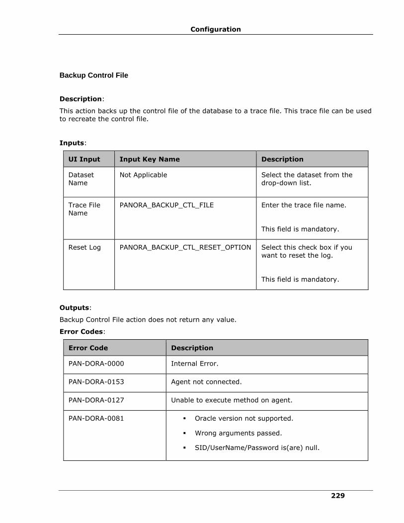
Configuration
229
Backup Control File
Description:
This action backs up the control file of the database to a trace file. This trace file can be used
to recreate the control file.
Inputs:
UI Input Input Key Name Description
Dataset
Name
Not Applicable
Select the dataset from the
drop-down list.
Trace File
Name
PANORA_BACKUP_CTL_FILE Enter the trace file name.
This field is mandatory.
Reset Log PANORA_BACKUP_CTL_RESET_OPTION Select this check box if you
want to reset the log.
This field is mandatory.
Outputs:
Backup Control File action does not return any value.
Error Codes:
Error Code Description
PAN-DORA-0000 Internal Error.
PAN-DORA-0153 Agent not connected.
PAN-DORA-0127 Unable to execute method on agent.
PAN-DORA-0081 ▪ Oracle version not supported.
▪ Wrong arguments passed.
▪ SID/UserName/Password is(are) null.
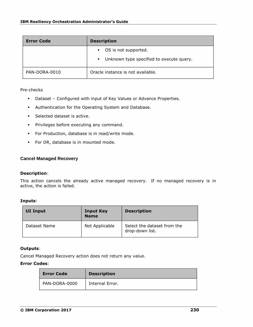
IBM Resiliency Orchestration Administrator’s Guide
© IBM Corporation 2017 230
Error Code Description
▪ OS is not supported.
▪ Unknown type specified to execute query.
PAN-DORA-0010 Oracle instance is not available.
Pre-checks
▪ Dataset – Configured with input of Key Values or Advance Properties.
▪ Authentication for the Operating System and Database.
▪ Selected dataset is active.
▪ Privileges before executing any command.
▪ For Production, database is in read/write mode.
▪ For DR, database is in mounted mode.
Cancel Managed Recovery
Description:
This action cancels the already active managed recovery. If no managed recovery is in
active, the action is failed.
Inputs:
UI Input Input Key
Name
Description
Dataset Name Not Applicable Select the dataset from the
drop-down list.
Outputs:
Cancel Managed Recovery action does not return any value.
Error Codes:
Error Code Description
PAN-DORA-0000 Internal Error.

Configuration
231
Error Code Description
PAN-DORA-0153 Agent not connected.
PAN-DORA-0127 Unable to execute method on agent.
PAN-DORA-0081 ▪ Oracle version not supported.
▪ Wrong arguments passed.
▪ SID/UserName/Password is(are) null.
▪ OS is not supported.
▪ Unknown type specified to execute query.
PAN-DORA-0010 Oracle instance is not available.
Pre-checks
▪ Dataset – Configured with input of Key Values or Advance Properties.
▪ Authentication for the Operating System and Database.
▪ Selected dataset is active.
▪ Privileges before executing any command.
▪ Database is in active managed recovery mode.
Check Archive Gap
Check Archive Gap - Gets the first archive gap information from the DR database.
Description:
This action gets the first archive gap information from the DR database. It checks the archive
gap and fetches Low or High sequence numbers. A value of -1 indicates no archive gap
found. Any value greater than -1 indicates the missing sequence number.
Inputs:
UI Input Input Key Name Description
Dataset Name Not Applicable Select the dataset from

IBM Resiliency Orchestration Administrator’s Guide
© IBM Corporation 2017 232
the drop-down list.
Outputs:
Output
Name
Output Key Name Description
Low Sequence
Number
PANORA_ARCHIVE_GAP_LOW_SEQ Low Sequence
number of missing
archive in range.
High
Sequence
Number
PANORA_ARCHIVE_GAP_HIGH_SEQ High Sequence
number of missing
archive in range.
Error Codes:
Error Code Description
PAN-DORA-0000 Internal Error.
PAN-DORA-0153 Agent not connected.
PAN-DORA-0127 Unable to execute method on agent.
PAN-DORA-0081 ▪ Oracle version not supported.
▪ Wrong arguments passed.
▪ SID/UserName/Password is(are) null.
▪ OS is not supported.
▪ Unknown type specified to execute
query.
PAN-DORA-0010 Oracle instance is not available.
Pre-checks
▪ Dataset – Configured with input of Key Values or Advance Properties.
▪ Authentication for the Operating System and Database.
▪ Selected dataset is active.
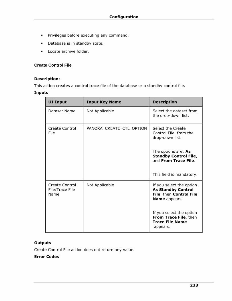
Configuration
233
▪ Privileges before executing any command.
▪ Database is in standby state.
▪ Locate archive folder.
Create Control File
Description:
This action creates a control trace file of the database or a standby control file.
Inputs:
UI Input Input Key Name Description
Dataset Name Not Applicable
Select the dataset from
the drop-down list.
Create Control
File
PANORA_CREATE_CTL_OPTION Select the Create
Control File, from the
drop-down list.
The options are: As
Standby Control File,
and From Trace File.
This field is mandatory.
Create Control
File/Trace File
Name
Not Applicable If you select the option
As Standby Control
File, then Control File
Name appears.
If you select the option
From Trace File, then
Trace File Name
appears.
Outputs:
Create Control File action does not return any value.
Error Codes:

IBM Resiliency Orchestration Administrator’s Guide
© IBM Corporation 2017 234
Error Code Description
PAN-DORA-0000 Internal Error.
PAN-DORA-0153 Agent not connected.
PAN-DORA-0127 Unable to execute method on agent.
PAN-DORA-0081 ▪ Oracle version not supported.
▪ Wrong arguments passed.
▪ SID/UserName/Password is(are) null.
▪ OS is not supported.
▪ Unknown type specified to execute
query.
PAN-DORA-0010 Oracle instance is not available.
Pre-checks
▪ Dataset – Configured with input of Key Values or Advance Properties.
▪ Authentication for the Operating System and Database.
▪ Selected dataset is active.
▪ Privileges before executing any command.
▪ If create control file option is from standby control file, then database should be on
Production
▪ If create control file option is from trace file, then database should be on DR.
▪ Locate folder.
Execute SQL
Description:
This action is used for executing any SQL command.
Inputs:
UI Input Input Key Name Description

Configuration
235
UI Input Input Key Name Description
Dataset Name Not Applicable
Select the dataset from the
drop-down list.
Check the Show All check
box to see all the Oracle
datasets that are discovered
on the “Server
Components” attached to
the group.
SQL to Execute PANORA_EXEC_SQL Enter the SQL command to
execute.
This field is mandatory.
Expected Output PANORA_PASS_CRITERIA Enter the expected output.
This field is optional.
Role PANORA_ROLE Enter the expected role.
This field is mandatory.
Note:
▪ If username is sys,
then the role is
sysdba. It is not
mandatory to enter
the role.
▪ If no role specified
then query will be
executed by sysdba
role.
Outputs:
Execute SQL action does not return any value.
Error Codes:

IBM Resiliency Orchestration Administrator’s Guide
© IBM Corporation 2017 236
Error Code Description
PAN-DORA-0000 Internal Error.
PAN-DORA-0153 Agent not connected.
PAN-DORA-0127 Unable to execute method on agent.
PAN-DORA-0081 ▪ Oracle version not supported.
▪ Wrong arguments passed.
▪ SID/UserName/Password
is(are) null.
▪ OS is not supported.
▪ Unknown type specified to
execute query.
PAN-DORA-0010 Oracle instance is not available.
Pre-checks
▪ Dataset – Configured with input of Key Values or Advance Properties.
▪ Authentication for the Operating System and Database.
▪ Selected dataset is active.
▪ Privileges before executing any command.
Execute SQL File
Execute SQL File - Executes any file which contains SQL command.
Description:
This action is used for executing any file which contains SQL command. The SQL command
can also contain a PL/SQL procedure or a set of individual SQL commands etc.
Inputs:
UI Input Input Key Name Description
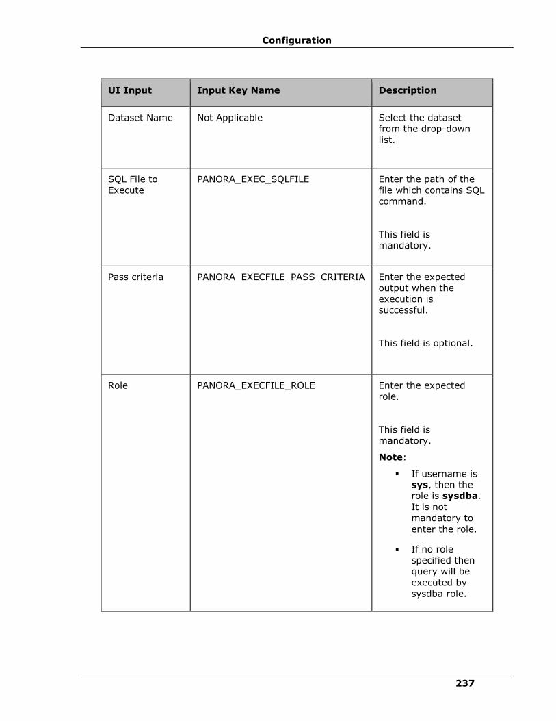
Configuration
237
UI Input Input Key Name Description
Dataset Name Not Applicable
Select the dataset
from the drop-down
list.
SQL File to
Execute
PANORA_EXEC_SQLFILE Enter the path of the
file which contains SQL
command.
This field is
mandatory.
Pass criteria PANORA_EXECFILE_PASS_CRITERIA Enter the expected
output when the
execution is
successful.
This field is optional.
Role PANORA_EXECFILE_ROLE Enter the expected
role.
This field is
mandatory.
Note:
▪ If username is
sys, then the
role is sysdba.
It is not
mandatory to
enter the role.
▪ If no role
specified then
query will be
executed by
sysdba role.
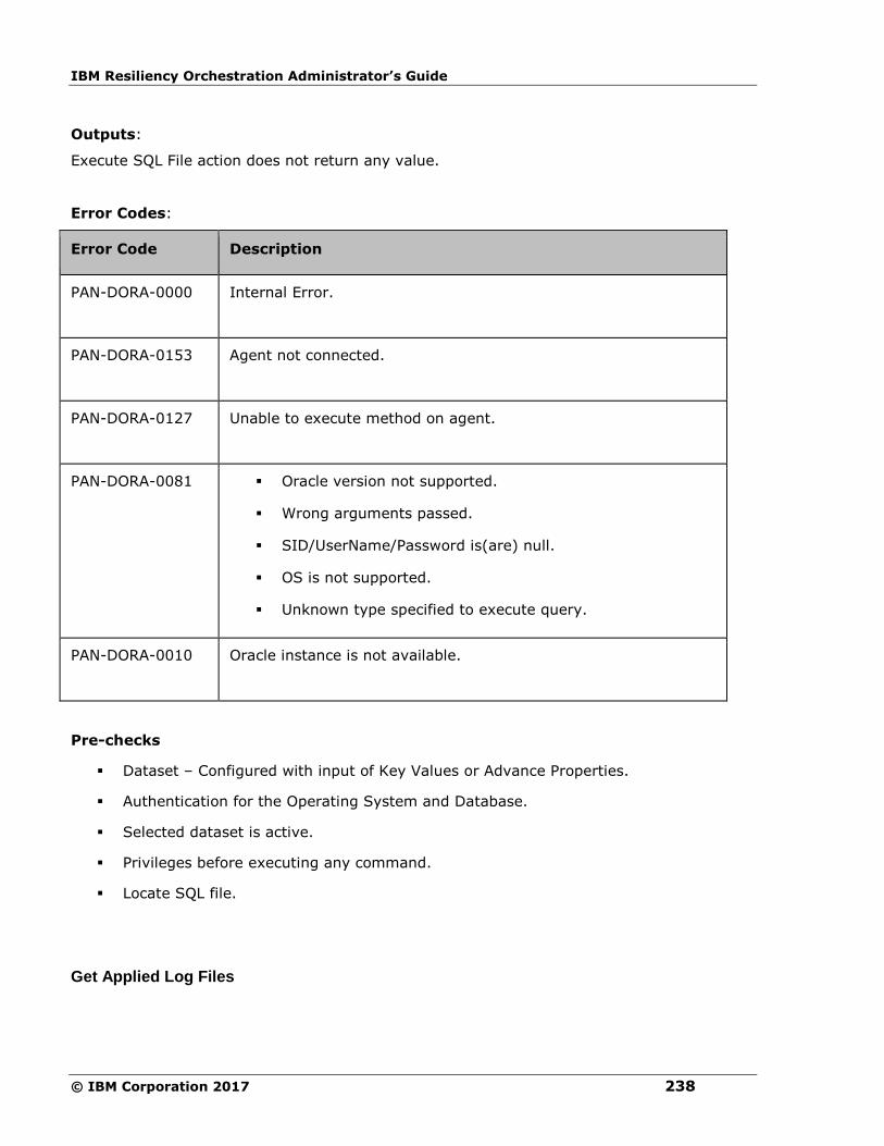
IBM Resiliency Orchestration Administrator’s Guide
© IBM Corporation 2017 238
Outputs:
Execute SQL File action does not return any value.
Error Codes:
Error Code Description
PAN-DORA-0000 Internal Error.
PAN-DORA-0153 Agent not connected.
PAN-DORA-0127 Unable to execute method on agent.
PAN-DORA-0081 ▪ Oracle version not supported.
▪ Wrong arguments passed.
▪ SID/UserName/Password is(are) null.
▪ OS is not supported.
▪ Unknown type specified to execute query.
PAN-DORA-0010 Oracle instance is not available.
Pre-checks
▪ Dataset – Configured with input of Key Values or Advance Properties.
▪ Authentication for the Operating System and Database.
▪ Selected dataset is active.
▪ Privileges before executing any command.
▪ Locate SQL file.
Get Applied Log Files
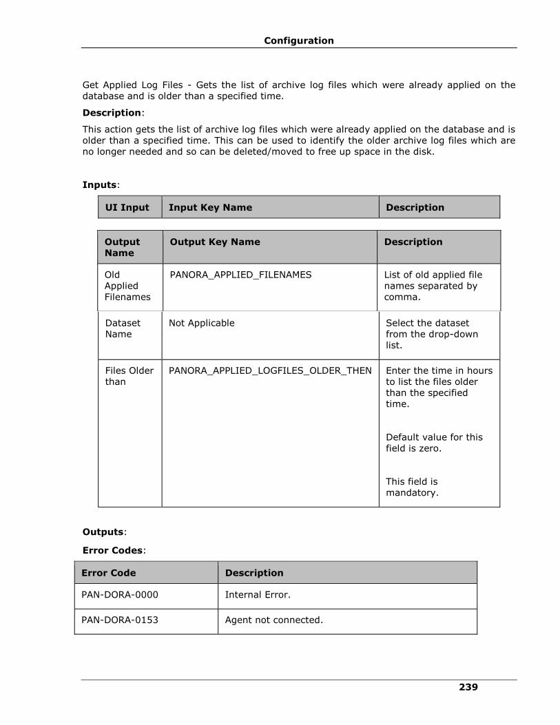
Configuration
239
Get Applied Log Files - Gets the list of archive log files which were already applied on the
database and is older than a specified time.
Description:
This action gets the list of archive log files which were already applied on the database and is
older than a specified time. This can be used to identify the older archive log files which are
no longer needed and so can be deleted/moved to free up space in the disk.
Inputs:
UI Input Input Key Name Description
Dataset
Name
Not Applicable
Select the dataset
from the drop-down
list.
Files Older
than
PANORA_APPLIED_LOGFILES_OLDER_THEN Enter the time in hours
to list the files older
than the specified
time.
Default value for this
field is zero.
This field is
mandatory.
Outputs:
Error Codes:
Error Code Description
PAN-DORA-0000 Internal Error.
PAN-DORA-0153 Agent not connected.
Output
Name
Output Key Name Description
Old
Applied
Filenames
PANORA_APPLIED_FILENAMES List of old applied file
names separated by
comma.

IBM Resiliency Orchestration Administrator’s Guide
© IBM Corporation 2017 240
Error Code Description
PAN-DORA-0127 Unable to execute method on agent.
PAN-DORA-0081 ▪ Oracle version not supported.
▪ Wrong arguments passed.
▪ SID/UserName/Password is(are) null.
▪ OS is not supported.
▪ Unknown type specified to execute query.
PAN-DORA-0010 Oracle instance is not available.
Pre-checks
▪ Dataset – Configured with input of Key Values or Advance Properties.
▪ Authentication for the Operating System and Database.
▪ Selected dataset is active.
▪ Privileges before executing any command.
▪ Database is in standby state.
▪ Locate archive folder and view its permissions.
Get Current Sequence Number
Get Current Sequence Number - Gets the current archive log sequence number.
Description:
This action gets the current archive log sequence number. This number would be the
sequence number of the last archived file if it is a production database and will be the
sequence number of the last applied file if it is a standby database.
Inputs:
UI Input Input Key Name Description
Dataset Name Not Applicable
Select the dataset from the drop-down
list.

Configuration
241
Outputs:
Output
Name
Output Key Name Description
Sequence
Number PANORA_GET_CURR_SEQ_NUM Current Sequence
number of the log
which got
archived/applied.
Error Codes:
Error Code Description
PAN-DORA-0000 Internal Error.
PAN-DORA-0153 Agent not connected.
PAN-DORA-0127 Unable to execute method on agent.
PAN-DORA-0081 ▪ Oracle version not supported.
▪ Wrong arguments passed.
▪ SID/UserName/Password is(are)
null.
▪ OS is not supported.
▪ Unknown type specified to execute
query.
PAN-DORA-0010 Oracle instance is not available.
Pre-checks
▪ Dataset – Configured with input of Key Values or Advance Properties.
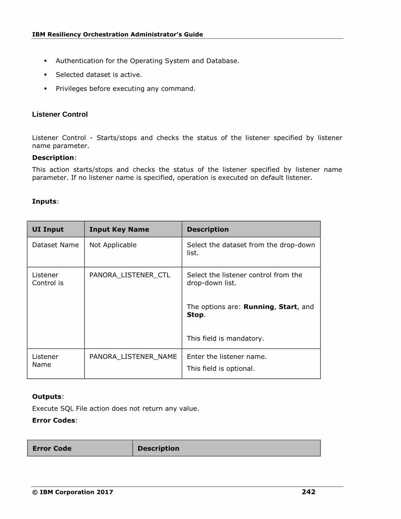
IBM Resiliency Orchestration Administrator’s Guide
© IBM Corporation 2017 242
▪ Authentication for the Operating System and Database.
▪ Selected dataset is active.
▪ Privileges before executing any command.
Listener Control
Listener Control - Starts/stops and checks the status of the listener specified by listener
name parameter.
Description:
This action starts/stops and checks the status of the listener specified by listener name
parameter. If no listener name is specified, operation is executed on default listener.
Inputs:
UI Input Input Key Name Description
Dataset Name Not Applicable
Select the dataset from the drop-down
list.
Listener
Control is
PANORA_LISTENER_CTL Select the listener control from the
drop-down list.
The options are: Running, Start, and
Stop.
This field is mandatory.
Listener
Name
PANORA_LISTENER_NAME Enter the listener name.
This field is optional.
Outputs:
Execute SQL File action does not return any value.
Error Codes:
Error Code Description

Configuration
243
Error Code Description
PAN-DORA-0000 Internal Error.
PAN-DORA-0153 Agent not connected.
PAN-DORA-0127 Unable to execute method on agent.
PAN-DORA-0081 ▪ Oracle version not supported.
▪ Wrong arguments passed.
▪ SID/UserName/Password is (are) null.
▪ OS is not supported.
▪ Unknown type specified to execute query.
PAN-DORA-0010 Oracle instance is not available.
PAN-DORA-0088 Operation not supported.
Pre-checks
▪ Dataset – Configured with input of Key Values or Advance Properties.
▪ Authentication for the Operating System and Database.
▪ Selected dataset is active.
▪ Privileges before executing any command.
▪ Listener is static or dynamic.
▪ If operation is start, then listener should be stopped
▪ If operation is stop, then listener should be running
Oracle Audit
Description
This RAL will give the transaction details during drill. We need to provide SQL queries to get
transaction details.
Below is the sample query that we need to provide in RAL input.
Oracle Command:
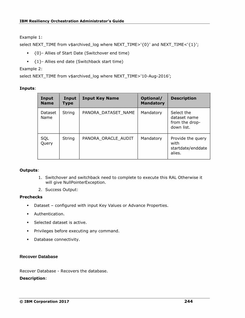
IBM Resiliency Orchestration Administrator’s Guide
© IBM Corporation 2017 244
Example 1:
select NEXT_TIME from v$archived_log where NEXT_TIME>'{0}' and NEXT_TIME<'{1}';
▪ {0}- Allies of Start Date (Switchover end time)
▪ {1}- Allies end date (Switchback start time)
Example 2:
select NEXT_TIME from v$archived_log where NEXT_TIME>'10-Aug-2016’;
Inputs:
Input
Name
Input
Type
Input Key Name Optional/
Mandatory
Description
Dataset
Name
String
PANORA_DATASET_NAME Mandatory Select the
dataset name
from the drop-
down list.
SQL
Query
String PANORA_ORACLE_AUDIT Mandatory Provide the query
with
startdate/enddate
alies.
Outputs:
1. Switchover and switchback need to complete to execute this RAL Otherwise it
will give NullPointerException.
2. Success Output:
Prechecks
▪ Dataset – configured with input Key Values or Advance Properties.
▪ Authentication.
▪ Selected dataset is active.
▪ Privileges before executing any command.
▪ Database connectivity.
Recover Database
Recover Database - Recovers the database.
Description:
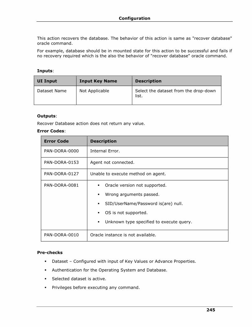
Configuration
245
This action recovers the database. The behavior of this action is same as "recover database"
oracle command.
For example, database should be in mounted state for this action to be successful and fails if
no recovery required which is the also the behavior of "recover database" oracle command.
Inputs:
UI Input Input Key Name Description
Dataset Name Not Applicable
Select the dataset from the drop-down
list.
Outputs:
Recover Database action does not return any value.
Error Codes:
Error Code Description
PAN-DORA-0000 Internal Error.
PAN-DORA-0153 Agent not connected.
PAN-DORA-0127 Unable to execute method on agent.
PAN-DORA-0081 ▪ Oracle version not supported.
▪ Wrong arguments passed.
▪ SID/UserName/Password is(are) null.
▪ OS is not supported.
▪ Unknown type specified to execute query.
PAN-DORA-0010 Oracle instance is not available.
Pre-checks
▪ Dataset – Configured with input of Key Values or Advance Properties.
▪ Authentication for the Operating System and Database.
▪ Selected dataset is active.
▪ Privileges before executing any command.

IBM Resiliency Orchestration Administrator’s Guide
© IBM Corporation 2017 246
▪ Database is mounted.
Shutdown Database
Shutdown Database - Shuts down the database.
Description:
This action shuts down the database. This assumes that the database is already started and
is running when this action is executed. It will fail if the database is already shutdown.
Inputs:
UI Input Input Key Name Description
Dataset
Name
Not Applicable
Select the dataset from the drop-
down list.
Shutdown
Mode
PANORA_SHUTDOWN_DB_MODE Select the shutdown mode from
the drop-down list.
The options are: normal,
immediate, transactional, and
abort.
This field is mandatory.
Outputs:
Shutdown Database action does not return any value.
Error Codes:
Error Code Description
PAN-DORA-0000 Internal Error.
PAN-DORA-0153 Agent not connected.

Configuration
247
Error Code Description
PAN-DORA-0127 Unable to execute method on agent.
PAN-DORA-0081 ▪ Oracle version not supported.
▪ Wrong arguments passed.
▪ SID/UserName/Password is(are) null.
▪ OS is not supported.
▪ Unknown type specified to execute query.
PAN-DORA-0010 Oracle instance is not available.
PAN-DORA-0009 Invalid shutdown mode.
Pre-checks
▪ Dataset – Configured with input of Key Values or Advance Properties.
▪ Authentication for the Operating System and Database.
▪ Selected dataset is active.
▪ Privileges before executing any command.
▪ Database is in operating state.
▪ Listener is static or dynamic.
Start Managed Recovery
Description:
This action starts the managed recovery process and log apply services in the database.
Inputs:
UI Input Input Key Name Description
Dataset Name Not Applicable
Select the dataset from the drop-
down list.
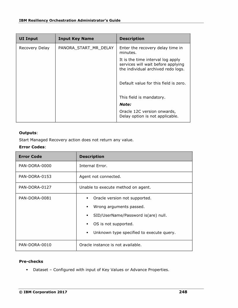
IBM Resiliency Orchestration Administrator’s Guide
© IBM Corporation 2017 248
UI Input Input Key Name Description
Recovery Delay PANORA_START_MR_DELAY Enter the recovery delay time in
minutes.
It is the time interval log apply
services will wait before applying
the individual archived redo logs.
Default value for this field is zero.
This field is mandatory.
Note:
Oracle 12C version onwards,
Delay option is not applicable.
Outputs:
Start Managed Recovery action does not return any value.
Error Codes:
Error Code Description
PAN-DORA-0000 Internal Error.
PAN-DORA-0153 Agent not connected.
PAN-DORA-0127 Unable to execute method on agent.
PAN-DORA-0081 ▪ Oracle version not supported.
▪ Wrong arguments passed.
▪ SID/UserName/Password is(are) null.
▪ OS is not supported.
▪ Unknown type specified to execute query.
PAN-DORA-0010 Oracle instance is not available.
Pre-checks
▪ Dataset – Configured with input of Key Values or Advance Properties.

Configuration
249
▪ Authentication for the Operating System and Database.
▪ Selected dataset is active.
▪ Privileges before executing any command.
▪ Apply should not be running.
Startup Database
Startup Database - Starts the database.
Description:
This action starts the database. This assumes that the database is not running when this
action is executed and will fail if the database is already running. In case of error, this would
leave the database in the shutdown state.
For example, if the database is in 'startup open' mode and it failed while opening the
database (succeeded in starting and mounting), it would not leave it in mounted state, but
leaves the database in shutdown state.
This operation requires a static entry in the listener.ora file so that IBM agent can connect to
the idle instance if the oracle database is shutdown.
Inputs:
UI Input Input Key Name Description
Dataset Name Not Applicable
Select the dataset from the
drop-down list.
Initialization
Type
PANORA_START_DB_INIT_TYPE Select the initialization type
from the drop-down list.
The options are: pfile, spfile,
and default.
This field is mandatory.
Database
Mode
PANORA_START_DB_MODE Select the database mode from
the drop-down list.
The options are: open, mount,
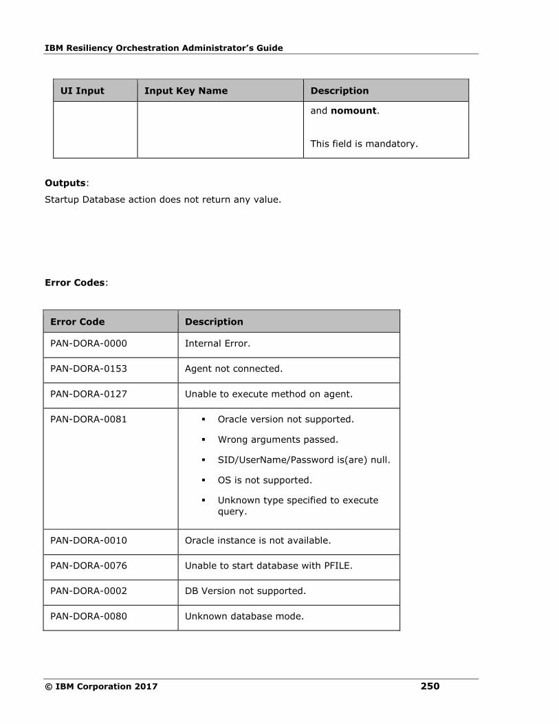
IBM Resiliency Orchestration Administrator’s Guide
© IBM Corporation 2017 250
UI Input Input Key Name Description
and nomount.
This field is mandatory.
Outputs:
Startup Database action does not return any value.
Error Codes:
Error Code Description
PAN-DORA-0000 Internal Error.
PAN-DORA-0153 Agent not connected.
PAN-DORA-0127 Unable to execute method on agent.
PAN-DORA-0081 ▪ Oracle version not supported.
▪ Wrong arguments passed.
▪ SID/UserName/Password is(are) null.
▪ OS is not supported.
▪ Unknown type specified to execute
query.
PAN-DORA-0010 Oracle instance is not available.
PAN-DORA-0076 Unable to start database with PFILE.
PAN-DORA-0002 DB Version not supported.
PAN-DORA-0080 Unknown database mode.

Configuration
251
PAN-DORA-0115 Unable to start database with SPFILE.
PAN-DORA-0072 Unable to start DB.
Pre-checks
▪ Dataset – Configured with input of Key Values or Advance Properties.
▪ Authentication for the Operating System and Database.
▪ Selected dataset is active.
▪ Privileges before executing any command.
▪ Database is in shutdown state.
▪ Locate pfile or spfile, depending on the initialisation file. .
▪ Listener is static or dynamic.
Switch Log File
Switch Log File - Switches the current redo log causing it to be archived/dumped.
Description:
This action switches the current redo log causing it to be archived/dumped. This assumes
that archive logging is enabled so that the switched log will be archived. If archive logging is
not enabled, switching of the logs will still succeed but it will not be archived.
Inputs:
UI Input Input Key
Name
Description
Dataset Name Not Applicable Select the dataset from the drop-
down list.
Outputs:
Output Name Output Key Name Description
Archived
Sequence
PANORA_SWITCH_LOG_SEQ_NUM Sequence number of
the log which got

IBM Resiliency Orchestration Administrator’s Guide
© IBM Corporation 2017 252
Number archived.
Archived File
Name
PANORA_SWITCH_LOG_FILE_NAME File name of the log
which got archived.
Error Codes:
Error Code Description
PAN-DORA-
0000
Internal Error.
PAN-DORA-
0153
Agent not connected.
PAN-DORA-
0127
Unable to execute method on agent.
PAN-DORA-
0081
▪ Oracle version not supported.
▪ Wrong arguments passed.
▪ SID/UserName/Password is(are) null.
▪ OS is not supported.
▪ Unknown type specified to execute
query.
PAN-DORA-
0010 Oracle instance is not available.
Pre-checks
▪ Dataset – Configured with input of Key Values or Advance Properties.
▪ Authentication for the Operating System and Database.
▪ Selected dataset is active.
▪ Privileges before executing any command.
▪ Database is on Production.
▪ Locate archive folder.

Configuration
253
Verify Applied Sequence Number
Verify Applied Sequence Number - Checks whether the archived log with the given sequence
number is applied in the database or not.
Description:
This action checks whether the archived log with the given sequence number is applied in the
database or not. It will also optionally wait for the archive log to be applied and will come out
only after it is applied.
Inputs:
UI Input Input Key Name Description
Dataset Name Not Applicable
Select the dataset
from the drop-down
list.
Sequence
Number to
Verify
PANORA_VERIFY_CURR_SEQ_NUM Enter the sequence
number of the
archived log to
verify.
This field is
mandatory.
Wait For Sync PANORA_WAIT_FOR_SYNC Select the check-
box to wait for the
archive log to be
applied.
This field is
mandatory.
Outputs:
Verify Applied Sequence Number action does not return any value.
Error Codes:
Error Code Description
PAN-DORA-0000 Internal Error.

IBM Resiliency Orchestration Administrator’s Guide
© IBM Corporation 2017 254
Error Code Description
PAN-DORA-0153 Agent not connected.
PAN-DORA-0127 Unable to execute method on agent.
PAN-DORA-0081 ▪ Oracle version not supported.
▪ Wrong arguments passed.
▪ SID/UserName/Password is(are) null.
▪ OS is not supported.
▪ Unknown type specified to execute query.
PAN-DORA-0183 Sequence not yet applied.
PAN-DORA-0010 Oracle instance is not available.
Pre-checks
▪ Dataset – Configured with input of Key Values or Advance Properties.
▪ Authentication for the Operating System and Database.
▪ Selected dataset is active.
▪ Privileges before executing any command.
Verify Database State
Description:
This action checks whether the database is in the given state or not.
Inputs:
UI Input Input Key Name Description
Dataset
Name
Not Applicable
Select the dataset from the
drop-down list.
Database
State
PANORA_VERIFY_DB_STATE Select the database state
from the drop-down list.

Configuration
255
UI Input Input Key Name Description
The options are: Open Read
Write(Production), Read
Only, Mounted, No Mount,
Primary, Standby, Instance
Not Running, and Archive
Log Mode.
This field is mandatory.
Note:
If user selects the Read only
option, it handles both Read
only and Read only with apply
open modes from Oracle 11G
onwards.
Outputs:
Verify Database State action does not return any value.
Error Codes:
Error Code Description
PAN-DORA-0000 Internal Error.
PAN-DORA-0153 Agent not connected.
PAN-DORA-0127 Unable to execute method on agent.
PAN-DORA-0081 ▪ Oracle version not supported.
▪ Wrong arguments passed.
▪ SID/UserName/Password is(are) null.
▪ OS is not supported.
▪ Unknown type specified to execute query.
PAN-DORA-0010 Oracle instance is not available.
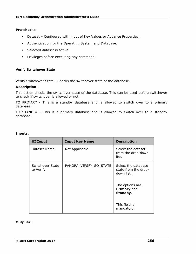
IBM Resiliency Orchestration Administrator’s Guide
© IBM Corporation 2017 256
Pre-checks
▪ Dataset – Configured with input of Key Values or Advance Properties.
▪ Authentication for the Operating System and Database.
▪ Selected dataset is active.
▪ Privileges before executing any command.
Verify Switchover State
Verify Switchover State - Checks the switchover state of the database.
Description:
This action checks the switchover state of the database. This can be used before switchover
to check if switchover is allowed or not.
TO PRIMARY - This is a standby database and is allowed to switch over to a primary
database.
TO STANDBY - This is a primary database and is allowed to switch over to a standby
database.
Inputs:
UI Input Input Key Name Description
Dataset Name Not Applicable
Select the dataset
from the drop-down
list.
Switchover State
to Verify
PANORA_VERIFY_SO_STATE Select the database
state from the drop-
down list.
The options are:
Primary and
Standby.
This field is
mandatory.
Outputs:

Configuration
257
Verify Switchover State action does not return any value.
Error Codes:
Error Code Description
PAN-DORA-
0000
Internal Error.
PAN-DORA-
0153
Agent not connected.
PAN-DORA-
0127
Unable to execute method on agent.
PAN-DORA-
0081
▪ Oracle version not supported.
▪ Wrong arguments passed.
▪ SID/UserName/Password is(are) null.
▪ OS is not supported.
▪ Unknown type specified to execute query.
PAN-DORA-
0010 Oracle instance is not available.
Pre-checks
▪ Dataset – Configured with input of Key Values or Advance Properties.
▪ Authentication for the Operating System and Database.
▪ Selected dataset is active.
▪ Privileges before executing any command.
▪ Dry Run Command.
PostgreSQL
Execute SQL
Description
This action executes the SQL by connecting to the database.

IBM Resiliency Orchestration Administrator’s Guide
© IBM Corporation 2017 258
Inputs
UI
Input
Input
type
Input Key Name Input
Optional/
Mandatory
Description
Dataset
Name
String PANPG_DATASET_NAME Mandatory Select the
dataset from
the drop-
down list
SQL String PANPG_SQL Mandatory Enter the
SQL that
needs to be
executed
Outputs
If the agent is unable to connect and execute the query on the database, then this action
fails.
Output Name Output Key Name Description
Output of the
SQL
PANPGS_SQL_RESULT Output of the
SQL
Pre-checks
▪ Dataset – configured with input Key Values or Advance Properties.
▪ Authentication.
▪ Selected dataset is active.
▪ Privileges before executing any command.
▪ Database connectivity.
Get Current Transaction Location
Description
This action get the current transaction location position of the database.

Configuration
259
Inputs
UI
Input
Input
Type
Input Key Name Input
Optional/
Mandatory
Description
Dataset
Name
String PANPG_DATASET_NAME Mandatory Select the
dataset
from the
drop-down
list.
Outputs
If the agent is unable to connect and execute the query on the database, then this action
fails.
Output Name Output Key Name Description
Transaction Log
Position
PANPG_CURR_LOG_POSITION Current Transaction Log
Position
Pre-checks
▪ Dataset – Configured with input of Key Values or Advance Properties.
▪ Authentication.
▪ Selected dataset is active.
▪ Privileges before executing any command.
▪ Database connectivity.
▪ Database is on Production.
Start Server
Description
This action starts the PostgreSQL server. It uses the pg_ctl command to start the server on
the PGDATA of the dataset which is configured in the action.
Inputs

IBM Resiliency Orchestration Administrator’s Guide
© IBM Corporation 2017 260
UI
Input
Input
Type
Input Key Name Input
Optional/
Mandatory
Description
Dataset
Name
String PANPG_DATASET_NAME Mandatory Select the
dataset from
the drop-
down list.
Outputs
If the agent is unable to start the server, then this action fails.
Pre-checks
▪ Dataset – Configured with input of Key Values or Advance Properties.
▪ Authentication.
▪ Selected dataset is active.
▪ Privileges before executing any command.
▪ Dataset credentials should be for Postgres.
▪ Locate PGDATA folder.
Stop Server
Description
This action stops the PostgreSQL server. It uses the pg_ctl command to stop the server on
the PGDATA of the dataset which is configured in the action.
Inputs
UI
Input
Input
Type
Input Key Name
Input
Optional/
Mandatory
Description
Dataset
Name
String PANPG_DATASET_NAME Mandatory Select the
dataset from
the drop-
down list
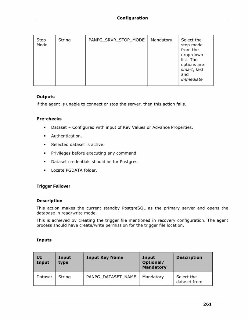
Configuration
261
Stop
Mode
String PANPG_SRVR_STOP_MODE Mandatory Select the
stop mode
from the
drop-down
list. The
options are:
smart, fast
and
immediate
Outputs
if the agent is unable to connect or stop the server, then this action fails.
Pre-checks
▪ Dataset – Configured with input of Key Values or Advance Properties.
▪ Authentication.
▪ Selected dataset is active.
▪ Privileges before executing any command.
▪ Dataset credentials should be for Postgres.
▪ Locate PGDATA folder.
Trigger Failover
Description
This action makes the current standby PostgreSQL as the primary server and opens the
database in read/write mode.
This is achieved by creating the trigger file mentioned in recovery configuration. The agent
process should have create/write permission for the trigger file location.
Inputs
UI
Input
Input
type
Input Key Name Input
Optional/
Mandatory
Description
Dataset String PANPG_DATASET_NAME Mandatory Select the
dataset from
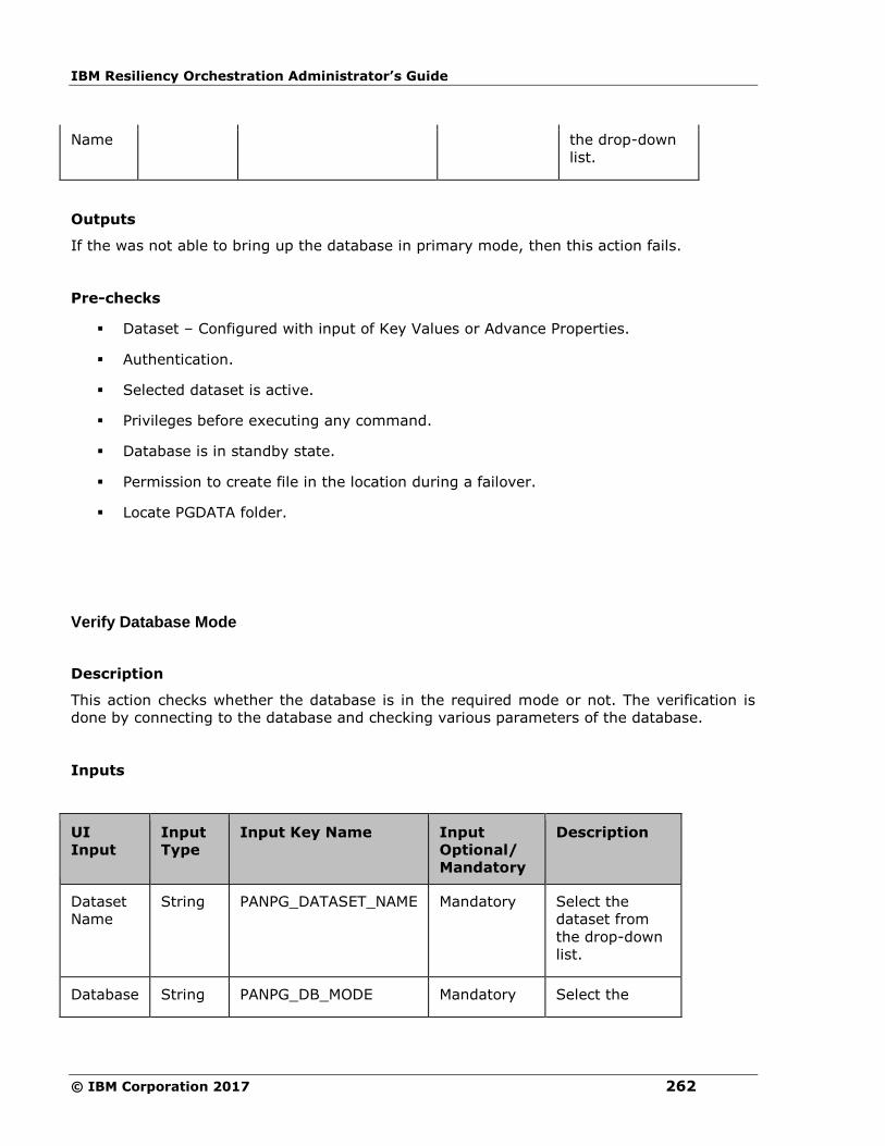
IBM Resiliency Orchestration Administrator’s Guide
© IBM Corporation 2017 262
Name the drop-down
list.
Outputs
If the was not able to bring up the database in primary mode, then this action fails.
Pre-checks
▪ Dataset – Configured with input of Key Values or Advance Properties.
▪ Authentication.
▪ Selected dataset is active.
▪ Privileges before executing any command.
▪ Database is in standby state.
▪ Permission to create file in the location during a failover.
▪ Locate PGDATA folder.
Verify Database Mode
Description
This action checks whether the database is in the required mode or not. The verification is
done by connecting to the database and checking various parameters of the database.
Inputs
UI
Input
Input
Type
Input Key Name Input
Optional/
Mandatory
Description
Dataset
Name
String PANPG_DATASET_NAME Mandatory Select the
dataset from
the drop-down
list.
Database String PANPG_DB_MODE Mandatory Select the
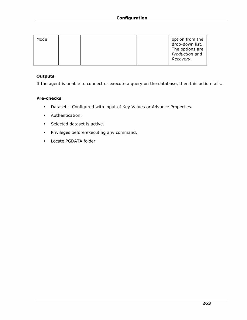
Configuration
263
Mode option from the
drop-down list.
The options are
Production and
Recovery
Outputs
If the agent is unable to connect or execute a query on the database, then this action fails.
Pre-checks
▪ Dataset – Configured with input of Key Values or Advance Properties.
▪ Authentication.
▪ Selected dataset is active.
▪ Privileges before executing any command.
▪ Locate PGDATA folder.

IBM Resiliency Orchestration Administrator’s Guide
© IBM Corporation 2017 264
Verify Transaction Received Location
Description
This action checks whether the database has received the given transaction log location or
not. Optionally it will wait for the database to receive the log until the given location.
Inputs
UI
Input
Input
Type
Input Key Name Input
Optional/
Mandatory
Description
Dataset
Name
String PANPG_DATASET_NAME Mandatory Select the
dataset
from the
drop-down
list
Log
Location
String PANPG_VERIFY_LOG_POSITION Mandatory Location of
the log that
needs to be
verified
Wait for
Sync
Check
box
PANPG_WAIT_FOR_SYNC Mandatory Wait for the
log to be
recevied
The possible value for PANPG_WAIT_FOR_SYNC key is either 1 or 0
Outputs
If the agent is unable to connect or execute a query on the database, then this action fails.
Pre-checks
▪ Dataset – Configured with input of Key Values or Advance Properties.
▪ Authentication.
▪ Selected dataset is active.
▪ Privileges before executing any command.

Configuration
265
▪ Database connectivity.
▪ Database is in standby state.
MySQL
Change Master
Description
This action changes the master information on DR database.
Inputs
Input
Name
Input
Type
Input Key Name Optional/
Mandatory
Description
Dataset
Name
String PANMYSQL_DATASET_NAME Mandatory Select the
dataset
from the
drop-down
list
Master
Host String PANMYSQL_CHANGE_MASTER_HOST Mandatory Master host
IP address
Master
Port
Integer PANMYSQL_CHANGE_MASTER_PORT Mandatory Master Port
Master
User
String PANMYSQL_CHANGE_MASTER_USER Mandatory Master User
Name
Master
Password
String PANMYSQL_CHANGE_MASTER_PASSWORD Mandatory Master
Password
Master
Log File
String PANMYSQL_CHANGE_MASTER_LOG_FILE Mandatory Master Log
File
Master
Log
Position
String PANMYSQL_CHANGE_MASTER_LOG_POS Mandatory Master Log
Position
Outputs
Action fails, if unable to change master details on DR database.

IBM Resiliency Orchestration Administrator’s Guide
© IBM Corporation 2017 266
Pre-checks
▪ Dataset – Configured with input of Key Values or Advance Properties.
▪ Authentication.
▪ Selected dataset is active.
▪ Privileges before executing any command.
▪ Database connectivity.
▪ Database is in standby state.
▪ Slave is in operation or not.
Execute SQL
Description
This action executes the SQL query by connecting to the database.
Inputs
Input
Name
Input
Type
Input Key Name Optional/
Mandatory
Description
Dataset
Name
String PANMYSQL_DATASET_NAME Mandatory Select the dataset
from the drop-down
list.
SQL String PANMYSQL_SQL Mandatory Enter the SQL query
that needs to be
executed.
Outputs
Output Name Output Key Name Description
Output of the
SQL
PANMYSQL_SQL_RESULT Output of the SQL

Configuration
267
Action fails, if the agent is unable to connect or execute a query on the database.
Pre-checks
▪ Dataset – configured with input Key Values or Advance Properties.
▪ Authentication.
▪ Selected dataset is active.
▪ Privileges before executing any command.
▪ Database connectivity.
Get Master Status
Description
This action gets the master status.
Inputs
Input
Name
Input
Type
Input Key Name Optional/
Mandatory
Description
Dataset
Name
String PANMYSQL_DATASET_NAME Mandatory Select the
dataset from
the drop-
down list.
Outputs
Action fails if the agent is unable to connect and execute the query on the database.
Output Name Output Key Name Description
Master Log File PANMYSQL_MASTER_LOG_FILE Master Log File
Master Log
Position
PANMYSQL_MASTER_LOG_POS Master Log Position
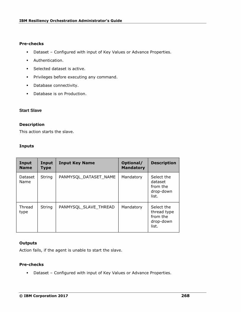
IBM Resiliency Orchestration Administrator’s Guide
© IBM Corporation 2017 268
Pre-checks
▪ Dataset – Configured with input of Key Values or Advance Properties.
▪ Authentication.
▪ Selected dataset is active.
▪ Privileges before executing any command.
▪ Database connectivity.
▪ Database is on Production.
Start Slave
Description
This action starts the slave.
Inputs
Input
Name
Input
Type
Input Key Name Optional/
Mandatory
Description
Dataset
Name
String PANMYSQL_DATASET_NAME Mandatory Select the
dataset
from the
drop-down
list.
Thread
type
String PANMYSQL_SLAVE_THREAD Mandatory Select the
thread type
from the
drop-down
list.
Outputs
Action fails, if the agent is unable to start the slave.
Pre-checks
▪ Dataset – Configured with input of Key Values or Advance Properties.

Configuration
269
▪ Authentication.
▪ Selected dataset is active.
▪ Privileges before executing any command.
▪ Database connectivity.
▪ Database is in standby state.
▪ Slave is in operation or not.
Stop Slave
Description
This action stops the slave.
Inputs
Input
Name
Input
Type
Input Key Name Optional/
Mandatory
Description
Dataset
Name
String PANMYSQL_DATASET_NAME Mandatory Select the
dataset
from the
drop-down
list.
Thread
type
String PANMYSQL_SLAVE_THREAD Mandatory Select the
thread type
from the
drop-down
list.
Outputs
Action fails, if the agent is unable to connect or stop the slave.
Pre-checks
▪ Dataset – Configured with input of Key Values or Advance Properties.
▪ Authentication.
▪ Selected dataset is active.

IBM Resiliency Orchestration Administrator’s Guide
© IBM Corporation 2017 270
▪ Privileges before executing any command.
▪ Database connectivity.
▪ Database is in standby state.
▪ Slave is in operation or not.
Verify Database Mode
Description
This action checks whether the database is in the required mode or not. The verification is
done by connecting to the database and checking various parameters of the database.
Inputs
Input
Name
Input
Type
Input Key Name Optional/
Mandatory
Description
Dataset
Name
String PANMYSQL_DATASET_NAME Mandatory Select the dataset
from the drop-down
list.
Database
Mode
String PANMYSQL_DB_MODE Mandatory Select the option
from the drop-down
list. The options are
Master and Slave.
Outputs
Action fails, if the agent is unable to connect or execute a query on the database.
Pre-checks
▪ Dataset – Configured with input of Key Values or Advance Properties.
▪ Authentication.
▪ Selected dataset is active.
▪ Privileges before executing any command.
▪ Database connectivity.

Configuration
271
Verify Received Log
Description
This action checks whether the database has received the given transaction log location or
not. Optionally it will wait for the database to receive the log until the given location.
Inputs
Input
Name
Input
Type
Input Key Name Optional/
Mandatory
Description
Dataset
Name
String PANMYSQL_DATASET_NAME Mandatory Select the dataset
from the drop-
down list.
Log File String PANMYSQL_VERIFY_LOG_FILE Mandatory Log file name that
needs to be
verified .
Log
Location
String PANMYSQL_VERIFY_LOG_POS Mandatory Location of the log
that needs to be
verified.
Wait for
Sync
Checkbox PANMYSQL_WAIT_FOR_SYNC Mandatory Wait for the log to
be received.
The possible values for PANMYSQL_WAIT_FOR_SYNC key is either 1 or 0.
Outputs
Action fails, if the agent is unable to connect or execute a query on the database.
Pre-checks
▪ Dataset – Configured with input of Key Values or Advance Properties.
▪ Authentication.
▪ Selected dataset is active.
▪ Privileges before executing any command.
▪ Database connectivity.
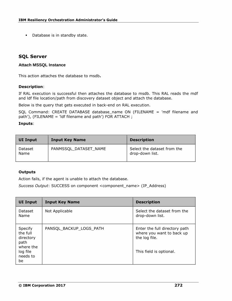
IBM Resiliency Orchestration Administrator’s Guide
© IBM Corporation 2017 272
▪ Database is in standby state.
SQL Server
Attach MSSQL Instance
This action attaches the database to msdb.
Description:
If RAL execution is successful then attaches the database to msdb. This RAL reads the mdf
and ldf file location/path from discovery dataset object and attach the database.
Below is the query that gets executed in back-end on RAL execution.
SQL Command: CREATE DATABASE database_name ON (FILENAME = 'mdf filename and
path'), (FILENAME = 'ldf filename and path') FOR ATTACH ;
Inputs:
UI Input Input Key Name Description
Dataset
Name
PANMSSQL_DATASET_NAME
Select the dataset from the
drop-down list.
Outputs
Action fails, if the agent is unable to attach the database.
Success Output: SUCCESS on component <component_name> (IP_Address)
UI Input Input Key Name Description
Dataset
Name
Not Applicable
Select the dataset from the
drop-down list.
Specify
the full
directory
path
where the
log file
needs to
be
PANSQL_BACKUP_LOGS_PATH Enter the full directory path
where you want to back up
the log file.
This field is optional.
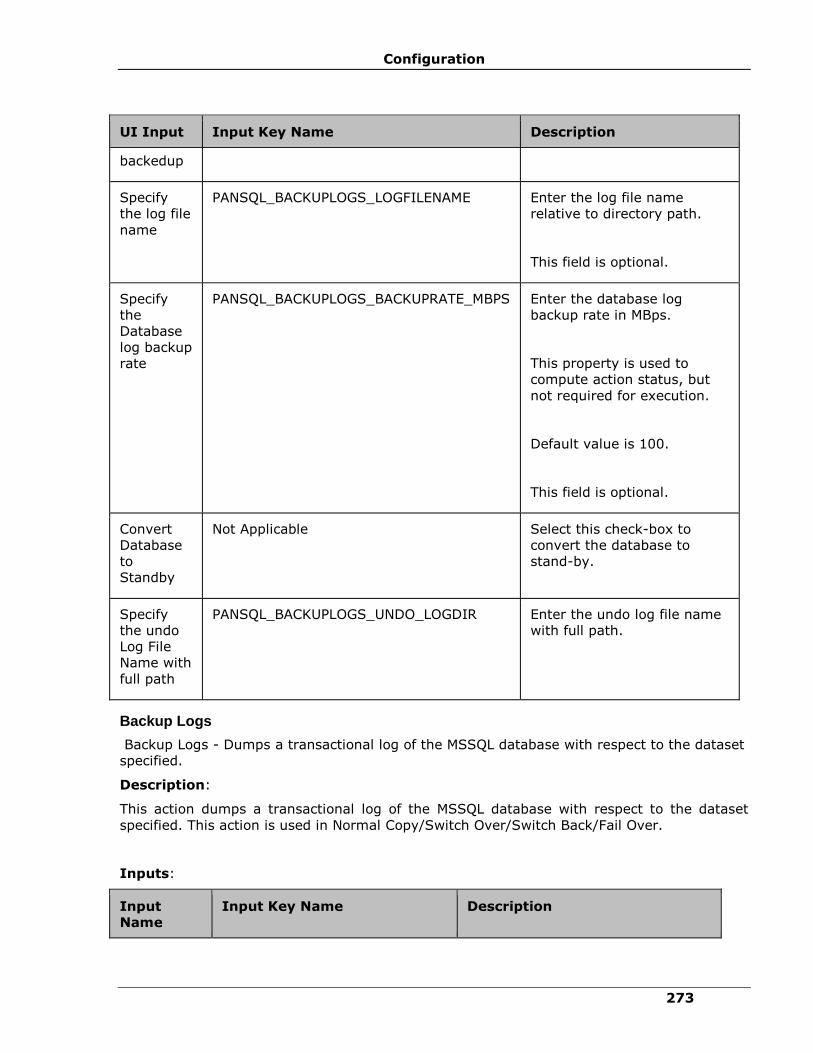
Configuration
273
UI Input Input Key Name Description
backedup
Specify
the log file
name
PANSQL_BACKUPLOGS_LOGFILENAME Enter the log file name
relative to directory path.
This field is optional.
Specify
the
Database
log backup
rate
PANSQL_BACKUPLOGS_BACKUPRATE_MBPS Enter the database log
backup rate in MBps.
This property is used to
compute action status, but
not required for execution.
Default value is 100.
This field is optional.
Convert
Database
to
Standby
Not Applicable Select this check-box to
convert the database to
stand-by.
Specify
the undo
Log File
Name with
full path
PANSQL_BACKUPLOGS_UNDO_LOGDIR Enter the undo log file name
with full path.
Backup Logs
Backup Logs - Dumps a transactional log of the MSSQL database with respect to the dataset
specified.
Description:
This action dumps a transactional log of the MSSQL database with respect to the dataset
specified. This action is used in Normal Copy/Switch Over/Switch Back/Fail Over.
Inputs:
Input
Name
Input Key Name Description
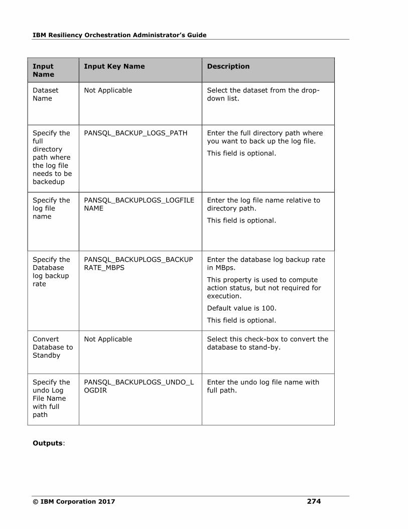
IBM Resiliency Orchestration Administrator’s Guide
© IBM Corporation 2017 274
Input
Name
Input Key Name Description
Dataset
Name
Not Applicable
Select the dataset from the drop-
down list.
Specify the
full
directory
path where
the log file
needs to be
backedup
PANSQL_BACKUP_LOGS_PATH Enter the full directory path where
you want to back up the log file.
This field is optional.
Specify the
log file
name
PANSQL_BACKUPLOGS_LOGFILE
NAME
Enter the log file name relative to
directory path.
This field is optional.
Specify the
Database
log backup
rate
PANSQL_BACKUPLOGS_BACKUP
RATE_MBPS
Enter the database log backup rate
in MBps.
This property is used to compute
action status, but not required for
execution.
Default value is 100.
This field is optional.
Convert
Database to
Standby
Not Applicable
Select this check-box to convert the
database to stand-by.
Specify the
undo Log
File Name
with full
path
PANSQL_BACKUPLOGS_UNDO_L
OGDIR
Enter the undo log file name with
full path.
Outputs:

Configuration
275
Output
Name
Output Key Name
Description
Return value(s) upon successful dump:
Log file
path
PANSQL_BACKUP_LOGS_PATH_OUTPUT Path where the log file is
dumped.
Log file
name
PANSQL_BACKUPLOGS_LOGFILENAME_OUTPUT Name of the log file relative
to
PANSQL_BACKUPLOGS_PATH.
Timestamp PANSQL_BACKUPLOGS_LOGFILE_TIMESTAMP Timestamp of the log file.
Checksum PANSQL_BACKUPLOGS_LOGFILE_CHECKSUM Checksum of the log file.
Last
transaction
ID
PANSQL_BACKUPLOGS_LASTTRANS_ID Last transaction ID.
Last
transaction
timestamp
PANSQL_BACKUPLOGS_LASTTRANS_TIMESTAMP Last transaction timestamp.
Return value(s) upon failure:
Error
message
PANSQL_BACKUPLOGS_ERROR Error message specifying the
nature of failure.
Error Codes:
Error Code Description
PAN-DSQL-0047 Common exception if any error occurs during action
execution on database.
PAN-DSQL-0080 Undo Log directory path is not set.
PAN-DSQL-0076 Backup log directory path is not set.
PAN-DSQL-0057 Unable to create log backup on database.
Notes:
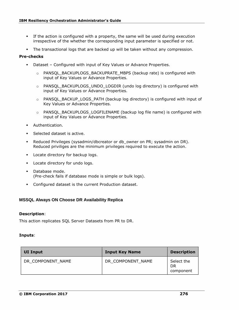
IBM Resiliency Orchestration Administrator’s Guide
© IBM Corporation 2017 276
▪ If the action is configured with a property, the same will be used during execution
irrespective of the whether the corresponding input parameter is specified or not.
▪ The transactional logs that are backed up will be taken without any compression.
Pre-checks
▪ Dataset – Configured with input of Key Values or Advance Properties.
o PANSQL_BACKUPLOGS_BACKUPRATE_MBPS (backup rate) is configured with
input of Key Values or Advance Properties.
o PANSQL_BACKUPLOGS_UNDO_LOGDIR (undo log directory) is configured with
input of Key Values or Advance Properties.
o PANSQL_BACKUP_LOGS_PATH (backup log directory) is configured with input of
Key Values or Advance Properties.
o PANSQL_BACKUPLOGS_LOGFILENAME (backup log file name) is configured with
input of Key Values or Advance Properties.
▪ Authentication.
▪ Selected dataset is active.
▪ Reduced Privileges (sysadmin/dbcreator or db_owner on PR; sysadmin on DR).
Reduced priviliges are the minimum privileges required to execute the action.
▪ Locate directory for backup logs.
▪ Locate directory for undo logs.
▪ Database mode.
(Pre-check fails if database mode is simple or bulk logs).
▪ Configured dataset is the current Production dataset.
MSSQL Always ON Choose DR Availability Replica
Description:
This action replicates SQL Server Datasets from PR to DR.
Inputs:
UI Input Input Key Name Description
DR_COMPONENT_NAME DR_COMPONENT_NAME Select the
DR
component

Configuration
277
UI Input Input Key Name Description
name from
the drop-
down list.
PRIMARY_COMPONENT_NAME PRIMARY_COMPONENT_NAME Select the
PR
component
name from
the drop-
down list.
PRIMARY_DATASET_NAME PRIMARY_DATASET_NAME Select the
PR database
name from
the drop-
down list.
DR_COMPONENT_IP DR_COMPONENT_IP Select the
DR
component
IP address
from the
drop-down
list.
DR_DATASET_COUNT DR_DATASET_COUNT Provide the
number of
DR
databases in
the text
box.
PRIMARY_COMPONENT_IP PRIMARY_COMPONENT_IP Select the
PR
component
IP address
from the
drop-down
list.
PRIMARY_DATASET_COUNT PRIMARY_DATASET_COUNT Provide the
number of
PR
databases in
the text
box.

IBM Resiliency Orchestration Administrator’s Guide
© IBM Corporation 2017 278
UI Input Input Key Name Description
DR_DATASET_NAME DR_DATASET_NAME Select the
DR database
name from
the drop-
down list.
Change DB Mode
Change DB Mode - Changes the database mode.
Description:
This action changes the database mode. You can change the database mode to online mode
or single user mode.
Inputs:
UI Input Input Key Name Description
Dataset Name Not Applicable Select the dataset from the drop-
down list.
Specify the new
mode
PANSQL_CHANGE_DB_MODE Select the mode to which you want
to change the current database
mode, from the drop-down list.
The options are: Recover DB, Change
to Single User, OFFLINE and ONLINE.
This field is mandatory.

Configuration
279
Outputs:
Output
Name
Output Key Name Description
Error
message
PANSQL_CHANGE_DB_MODE_ERROR Error message
specifying the nature
of failure while
changing DB mode.
Error Codes:
Error Code Description
PAN-DSQL-0047 Common exception if any error occurs
during action execution on database.
Pre-checks
▪ Dataset – Configured with input of Key Values or Advance Properties.
o PANSQL_CHANGE_DB_MODE (changeDBModeKey) is configured with input of
Key Values or Advance Properties.
▪ Authentication.
▪ Selected dataset is active.
▪ Reduced Privileges (sysadmin/dbcreator on PR; sysadmin on DR).
Reduced priviliges are the minimum privileges required to execute the action.
Choose DR Availability Replica
Choose DR Availability Replica - Chooses MSSQL AlwaysON available DR replica to operate
for further actions.
Description
This action is used to get a list of DR Replica of AlwaysON for the configured group. User can
choose one of the DR Replica for further actions. This action gives a flexibility during test
exercise or failover to choose DR Replica that is more recent or consistent.
Pre-requisites:
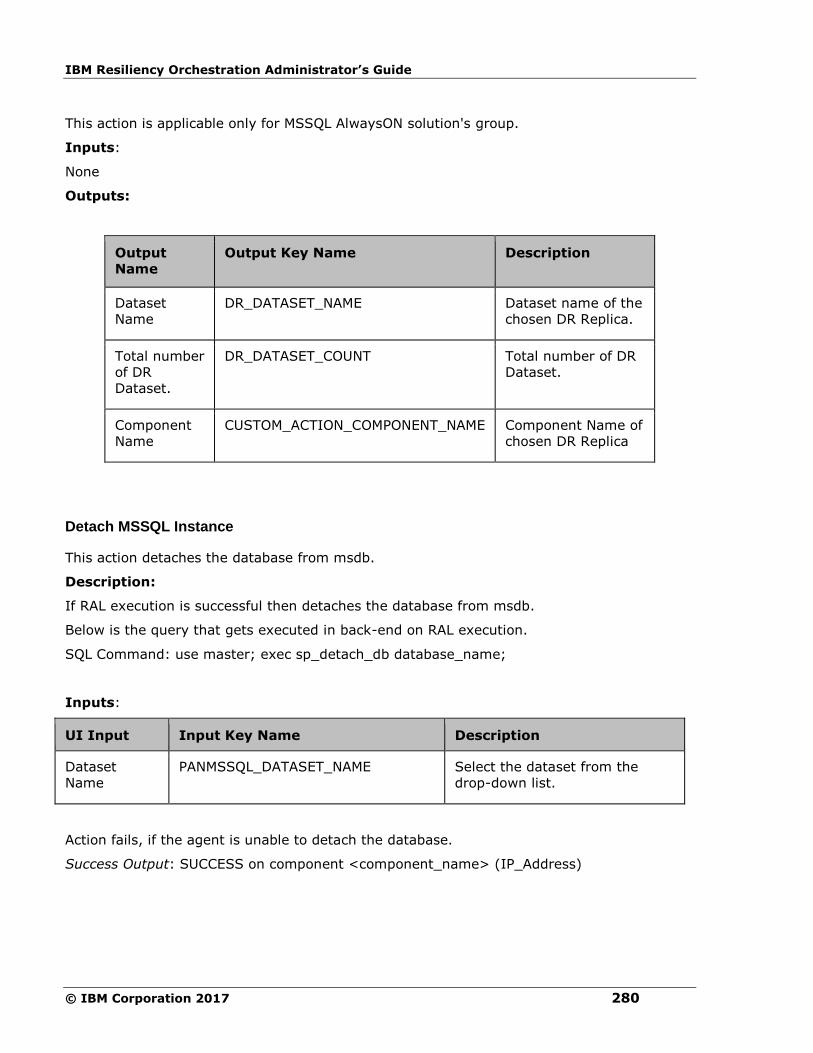
IBM Resiliency Orchestration Administrator’s Guide
© IBM Corporation 2017 280
This action is applicable only for MSSQL AlwaysON solution's group.
Inputs:
None
Outputs:
Output
Name
Output Key Name
Description
Dataset
Name
DR_DATASET_NAME Dataset name of the
chosen DR Replica.
Total number
of DR
Dataset.
DR_DATASET_COUNT Total number of DR
Dataset.
Component
Name
CUSTOM_ACTION_COMPONENT_NAME Component Name of
chosen DR Replica
Detach MSSQL Instance
This action detaches the database from msdb.
Description:
If RAL execution is successful then detaches the database from msdb.
Below is the query that gets executed in back-end on RAL execution.
SQL Command: use master; exec sp_detach_db database_name;
Inputs:
UI Input Input Key Name Description
Dataset
Name
PANMSSQL_DATASET_NAME Select the dataset from the
drop-down list.
Action fails, if the agent is unable to detach the database.
Success Output: SUCCESS on component <component_name> (IP_Address)
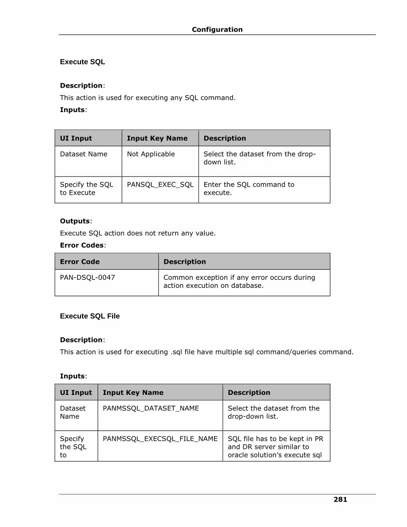
Configuration
281
Execute SQL
Description:
This action is used for executing any SQL command.
Inputs:
UI Input Input Key Name Description
Dataset Name Not Applicable
Select the dataset from the drop-
down list.
Specify the SQL
to Execute
PANSQL_EXEC_SQL Enter the SQL command to
execute.
Outputs:
Execute SQL action does not return any value.
Error Codes:
Error Code Description
PAN-DSQL-0047 Common exception if any error occurs during
action execution on database.
Execute SQL File
Description:
This action is used for executing .sql file have multiple sql command/queries command.
Inputs:
UI Input Input Key Name Description
Dataset
Name
PANMSSQL_DATASET_NAME
Select the dataset from the
drop-down list.
Specify
the SQL
to
PANMSSQL_EXECSQL_FILE_NAME SQL file has to be kept in PR
and DR server similar to
oracle solution’s execute sql

IBM Resiliency Orchestration Administrator’s Guide
© IBM Corporation 2017 282
Execute file RAL.
Note:
The file can have multiple
commands, separated by a
comma and saved with .sql
extension.
Outputs:
Displays the sql execution log of the sql file.
Error Codes:
Error Code Description
PAN_DSQL_0077 Common exception if any error occurs during
action execution on database.
Note:
Execute SQL File RAL fails, if the path has space in between the folder name.
Get DB Mode
Description:
This action is used to get the current mode of the database.
Inputs:
UI Input Input Key Name Description
Dataset
Name
PANMSSQL_DATASET_NAME
Select the dataset from the
drop-down list.
Outputs:
Output Name Output Key Name Description

Configuration
283
Message PANSQL_DB_MODE_STR Gives information on the
current database mode.
Code PANSQL_DB_MODE_CODE Code corresponding to the
message.
Error Codes:
Error Code Description
PAN-DSQL-
0047
Common exception if any error
occurs during action execution on
database.
Load Logs
Load Logs - Loads/applies a transactional log of the MSSQL database with respect to the
dataset specified.
Description:
This action loads/applies a transactional log of the MSSQL database with respect to the
dataset specified. This action is used in Normal Copy/Switch Over/Switch Back/Fail Over.
Inputs:
UI Input Input Key Name Description
Dataset Name Not Applicable
Select the dataset from
the drop-down list.
Specify the full
directory path
where the log file
needs to be loaded
PANSQL_LOADLOGS_PATH Enter the full directory
path where you want
to load/apply the log
file.
This field is optional.
Specify the list of
log file names to
restore
PANSQL_LOADLOGS_LOGFI
LES
Enter the log file name
and click Add.
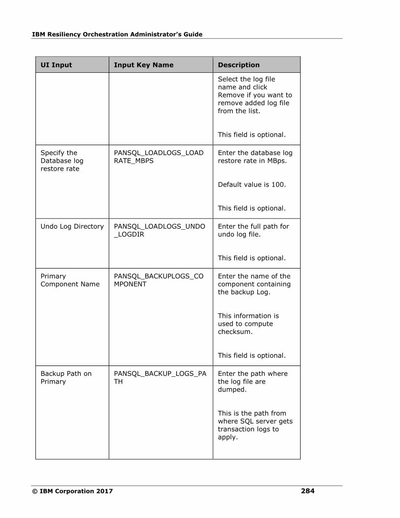
IBM Resiliency Orchestration Administrator’s Guide
© IBM Corporation 2017 284
UI Input Input Key Name Description
Select the log file
name and click
Remove if you want to
remove added log file
from the list.
This field is optional.
Specify the
Database log
restore rate
PANSQL_LOADLOGS_LOAD
RATE_MBPS
Enter the database log
restore rate in MBps.
Default value is 100.
This field is optional.
Undo Log Directory PANSQL_LOADLOGS_UNDO
_LOGDIR
Enter the full path for
undo log file.
This field is optional.
Primary
Component Name
PANSQL_BACKUPLOGS_CO
MPONENT
Enter the name of the
component containing
the backup Log.
This information is
used to compute
checksum.
This field is optional.
Backup Path on
Primary
PANSQL_BACKUP_LOGS_PA
TH
Enter the path where
the log file are
dumped.
This is the path from
where SQL server gets
transaction logs to
apply.
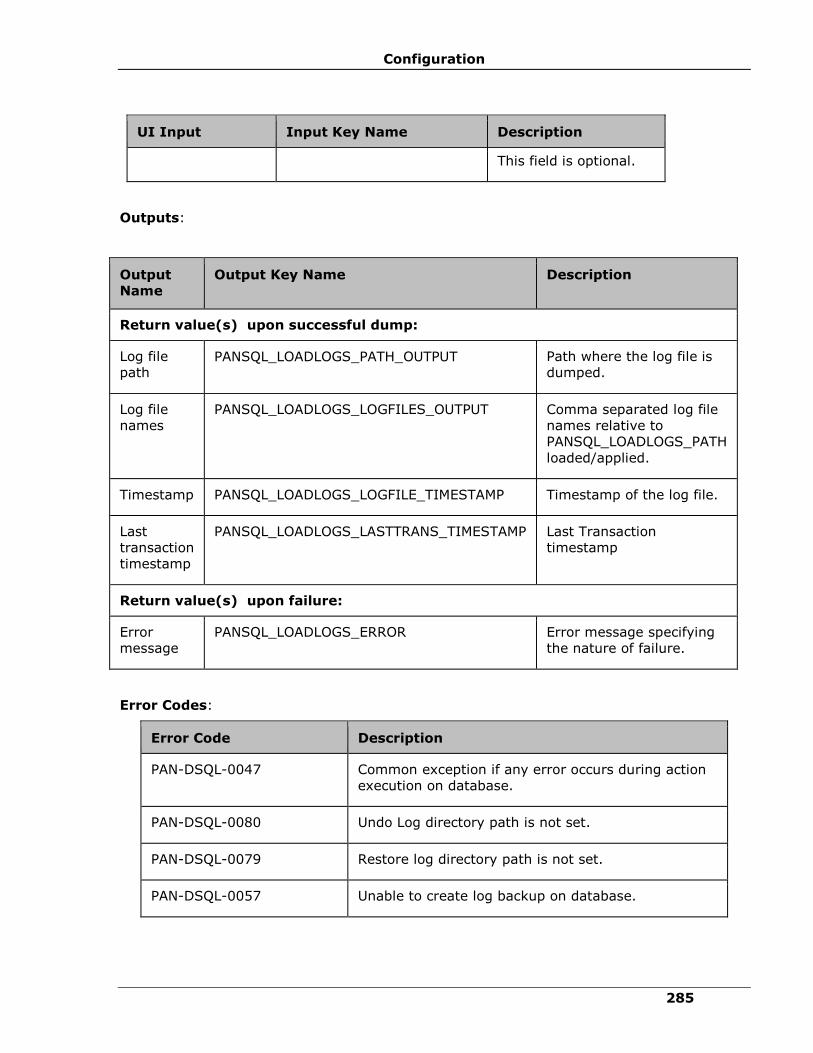
Configuration
285
UI Input Input Key Name Description
This field is optional.
Outputs:
Output
Name
Output Key Name
Description
Return value(s) upon successful dump:
Log file
path PANSQL_LOADLOGS_PATH_OUTPUT Path where the log file is
dumped.
Log file
names
PANSQL_LOADLOGS_LOGFILES_OUTPUT Comma separated log file
names relative to
PANSQL_LOADLOGS_PATH
loaded/applied.
Timestamp PANSQL_LOADLOGS_LOGFILE_TIMESTAMP Timestamp of the log file.
Last
transaction
timestamp
PANSQL_LOADLOGS_LASTTRANS_TIMESTAMP Last Transaction
timestamp
Return value(s) upon failure:
Error
message
PANSQL_LOADLOGS_ERROR Error message specifying
the nature of failure.
Error Codes:
Error Code Description
PAN-DSQL-0047 Common exception if any error occurs during action
execution on database.
PAN-DSQL-0080 Undo Log directory path is not set.
PAN-DSQL-0079 Restore log directory path is not set.
PAN-DSQL-0057 Unable to create log backup on database.

IBM Resiliency Orchestration Administrator’s Guide
© IBM Corporation 2017 286
Note:
If the action is configured with a property, the same will be used during execution
irrespective of the whether the corresponding input parameter is specified or not.
Pre-checks
▪ Dataset – Configured with input of Key Values or Advance Properties.
▪ PANSQL_LOADLOGS_PATH (load logs path) is configured with input of Key Values
or Advance Properties.
▪ PANSQL_LOADLOGS_LOGFILES (log file name) is configured with input of Key
Values or Advance Properties.
▪ PANSQL_LOADLOGS_LOADRATE_MBPS (logs load rate) is configured with input of
Key Values or Advance Properties.
▪ PANSQL_LOADLOGS_UNDO_LOGDIR (undo directory path) is configured with
input of Key Values or Advance Properties.
▪ PANSQL_BACKUP_LOGS_PATH (backup path on primary) is configured with input
of Key Values or Advance Properties.
▪ Authentication.
▪ Selected dataset is active.
▪ Reduced Privileges (sysadmin/dbcreator on PR; sysadmin on DR).
Reduced priviliges are the minimum privileges required to execute the action.
▪ Locate directory for load logs.
▪ Checksum for files on backup of primary.
▪ Configured dataset is the current DR dataset.
Start MSSQL Instance
This action starts mssql instance server.
Description:
If RAL execution is successful then starts mssql instance server.
Below is the query that gets executed in back-end on RAL execution.
SQL Command: exec net start /y mssqlserver;

Configuration
287
Inputs:
UI Input Input Key Name Description
Dataset
Name
PANMSSQL_DATASET_NAME
Select the dataset from the
drop-down list.
Outputs:
Action fails, if the agent is unable to start mssql instance server.
Success Output: The SQL Server Agent (MSSQLSERVER) service was started successfully. on
component (IP_Address)
Stop MSSQL Instance
This action stops mssql instance.
Description:
If RAL execution is successful then stop mssql instance.
Below is the query that gets executed in back-end on RAL execution.
SQL Command: exec net stop /y mssqlserver;
Inputs:
UI Input Input Key Name Description
Dataset
Name
PANMSSQL_DATASET_NAME Select the dataset from the
drop-down list.
Outputs:
Action fails, if the agent is unable to stop mssql instance.
Success Output: The SQL Server (MSSQLSERVER) service was stopped successfully. on
component (IP_Address) Additional info: {} <component_name> (IP_Address).
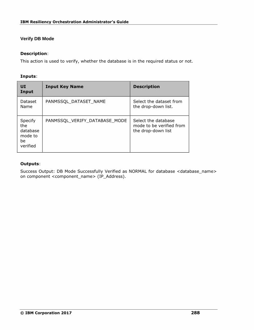
IBM Resiliency Orchestration Administrator’s Guide
© IBM Corporation 2017 288
Verify DB Mode
Description:
This action is used to verify, whether the database is in the required status or not.
Inputs:
UI
Input
Input Key Name Description
Dataset
Name
PANMSSQL_DATASET_NAME
Select the dataset from
the drop-down list.
Specify
the
database
mode to
be
verified
PANMSSQL_VERIFY_DATABASE_MODE Select the database
mode to be verified from
the drop-down list
Outputs:
Success Output: DB Mode Successfully Verified as NORMAL for database <database_name>
on component <component_name> (IP_Address).
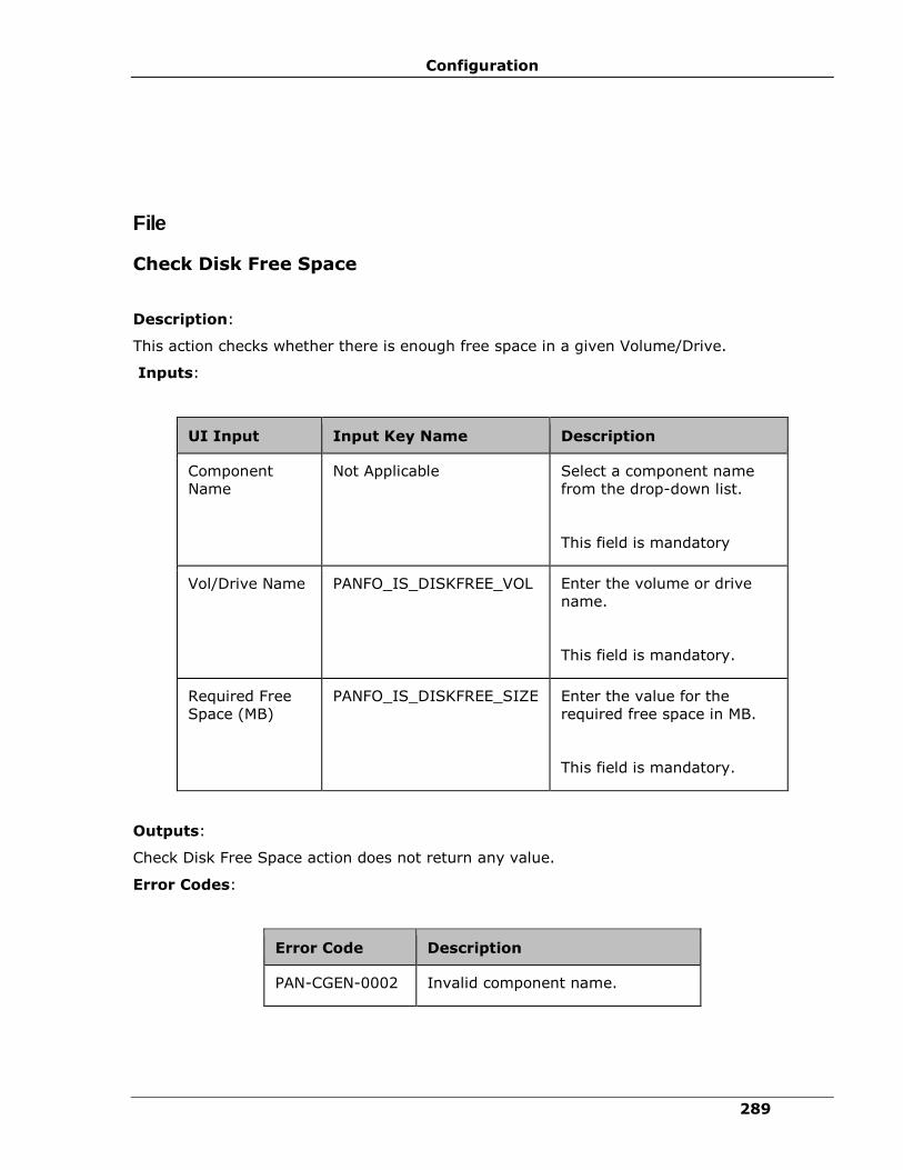
Configuration
289
File
Check Disk Free Space
Description:
This action checks whether there is enough free space in a given Volume/Drive.
Inputs:
UI Input Input Key Name Description
Component
Name
Not Applicable Select a component name
from the drop-down list.
This field is mandatory
Vol/Drive Name PANFO_IS_DISKFREE_VOL Enter the volume or drive
name.
This field is mandatory.
Required Free
Space (MB)
PANFO_IS_DISKFREE_SIZE Enter the value for the
required free space in MB.
This field is mandatory.
Outputs:
Check Disk Free Space action does not return any value.
Error Codes:
Error Code Description
PAN-CGEN-0002 Invalid component name.

IBM Resiliency Orchestration Administrator’s Guide
© IBM Corporation 2017 290
Pre-checks
▪ Login credentials.
▪ Availability of free disk space in the server.
▪ Locate Volume/Drive.
Check File Existence
Description:
This action checks whether a given file or directory exists or not.
Inputs:
UI Input Input Key Name Description
Component
Name
Not Applicable
Select a component name
from the drop-down list.
This field is mandatory
File/Directory
Name
PANFO_IS_FILEPATH_EXIST Enter the file or directory
name.
This field is mandatory.
Outputs:
Check File Existence action does not return any value.
Error Codes:
Error Code Description
PAN-CGEN-0002 Invalid component name.
Pre-checks
▪ Login credentials.
▪ Locate folder and file.
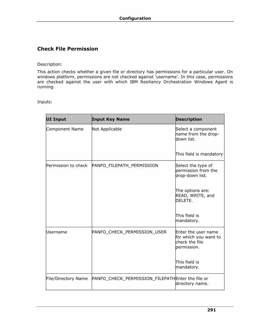
Configuration
291
Check File Permission
Description:
This action checks whether a given file or directory has permissions for a particular user. On
windows platform, permissions are not checked against 'username'. In this case, permissions
are checked against the user with which IBM Resiliency Orchestration Windows Agent is
running.
Inputs:
UI Input Input Key Name Description
Component Name Not Applicable
Select a component
name from the drop-
down list.
This field is mandatory
Permission to check PANFO_FILEPATH_PERMISSION Select the type of
permission from the
drop-down list.
The options are:
READ, WRITE, and
DELETE.
This field is
mandatory.
Username PANFO_CHECK_PERMISSION_USER Enter the user name
for which you want to
check the file
permission.
This field is
mandatory.
File/Directory Name PANFO_CHECK_PERMISSION_FILEPATH Enter the file or
directory name.

IBM Resiliency Orchestration Administrator’s Guide
© IBM Corporation 2017 292
UI Input Input Key Name Description
This field is
mandatory.
Outputs:
Check File Permission action does not return any value.
Error Codes:
Error Code Description
PAN-CGEN-0002 Invalid component name.
Limitations:
Not supported when target server is Windows and managed remotely [Agentless model].
Pre-checks
▪ Login credentials.
▪ User permission.
▪ Locate folder and file.
Copy File
Description:
This action copies the file(s) from one path to another path.
Inputs:
UI Input Input Key Name Description
Component
Name
Not Applicable
Select a component name from
the drop-down list.
This field is mandatory
Source File PANFO_COPYFILE_SRC Enter the file name and path
from where you want to copy
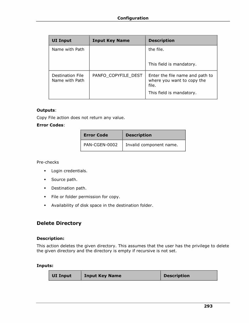
Configuration
293
UI Input Input Key Name Description
Name with Path the file.
This field is mandatory.
Destination File
Name with Path
PANFO_COPYFILE_DEST Enter the file name and path to
where you want to copy the
file.
This field is mandatory.
Outputs:
Copy File action does not return any value.
Error Codes:
Error Code Description
PAN-CGEN-0002 Invalid component name.
Pre-checks
▪ Login credentials.
▪ Source path.
▪ Destination path.
▪ File or folder permission for copy.
▪ Availability of disk space in the destination folder.
Delete Directory
Description:
This action deletes the given directory. This assumes that the user has the privilege to delete
the given directory and the directory is empty if recursive is not set.
Inputs:
UI Input Input Key Name Description
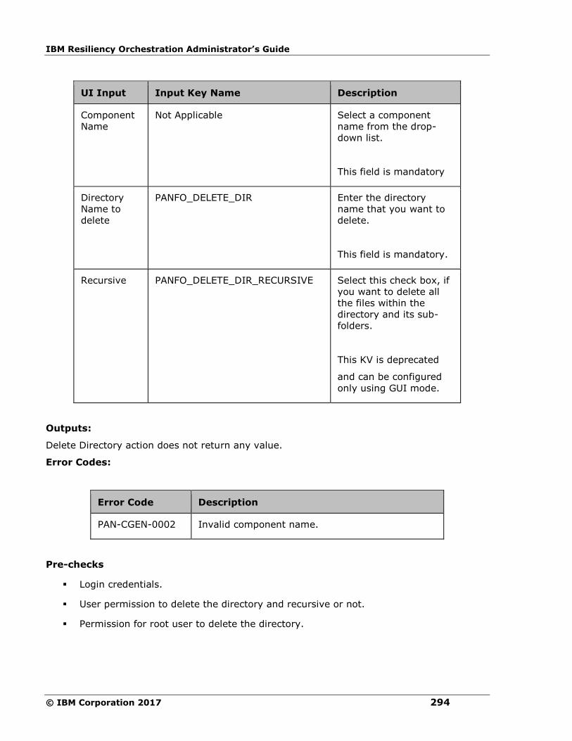
IBM Resiliency Orchestration Administrator’s Guide
© IBM Corporation 2017 294
UI Input Input Key Name Description
Component
Name
Not Applicable
Select a component
name from the drop-
down list.
This field is mandatory
Directory
Name to
delete
PANFO_DELETE_DIR Enter the directory
name that you want to
delete.
This field is mandatory.
Recursive PANFO_DELETE_DIR_RECURSIVE Select this check box, if
you want to delete all
the files within the
directory and its sub-
folders.
This KV is deprecated
and can be configured
only using GUI mode.
Outputs:
Delete Directory action does not return any value.
Error Codes:
Error Code Description
PAN-CGEN-0002 Invalid component name.
Pre-checks
▪ Login credentials.
▪ User permission to delete the directory and recursive or not.
▪ Permission for root user to delete the directory.

Configuration
295
Delete File
Delete File - Deletes the specified file.
Description:
This action deletes the given file. This assumes that the user has the privilege to delete the
given file. File delete action deletes a file if underlying system allows it to delete for the user
(Generally Administrator user), and the OS agent is running. On windows, some of the
advanced permission settings like 'delete deny', are effected only when user tries to delete
from explorer. However it is allowed to delete from cmd.exe. In such case, File delete action
will delete the file.
Inputs:
UI Input Input Key Name Description
Component
Name
Not Applicable
Select a component name from
the drop-down list.
This field is mandatory
File Name to
delete
PANFO_DELETE_FILE Enter the file name that you want
to delete.
This field is mandatory.
Outputs:
Delete File action does not return any value.
Error Codes:
Error Code Description
PAN-CGEN-0002 Invalid component name.
Note:
This action deletes files in the sub-directory also.
Pre-checks
▪ Login credentials.
▪ Locate file.
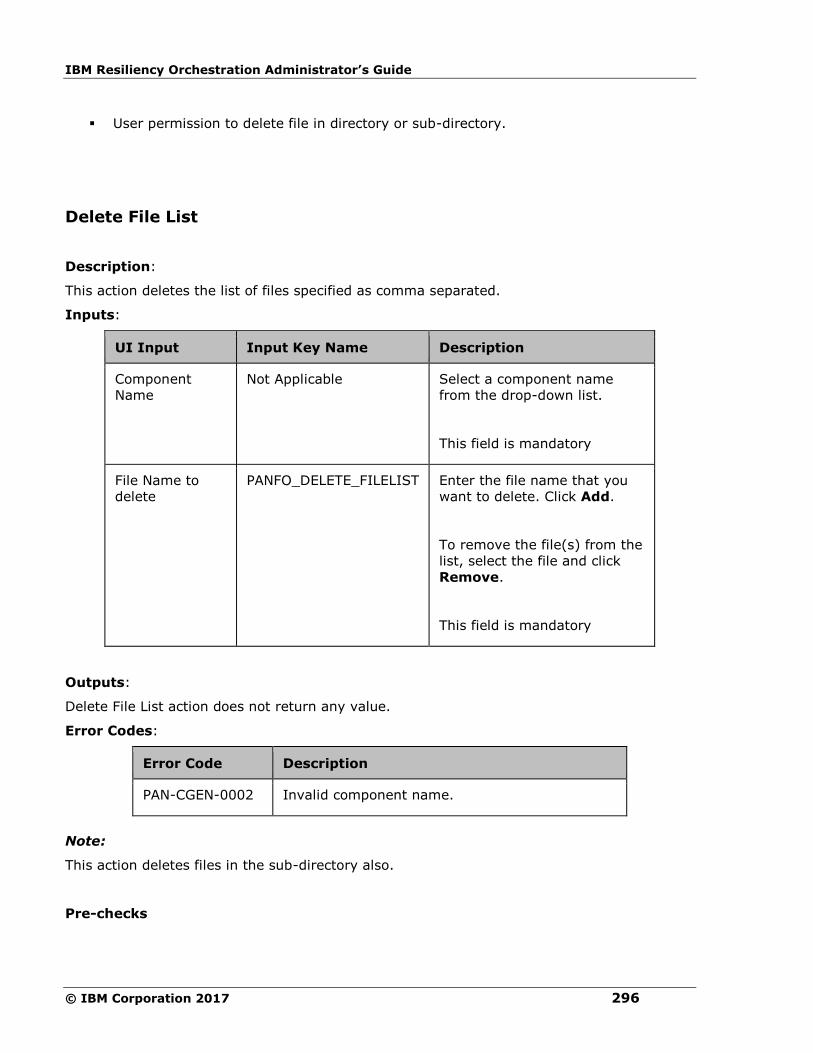
IBM Resiliency Orchestration Administrator’s Guide
© IBM Corporation 2017 296
▪ User permission to delete file in directory or sub-directory.
Delete File List
Description:
This action deletes the list of files specified as comma separated.
Inputs:
UI Input Input Key Name Description
Component
Name
Not Applicable
Select a component name
from the drop-down list.
This field is mandatory
File Name to
delete
PANFO_DELETE_FILELIST Enter the file name that you
want to delete. Click Add.
To remove the file(s) from the
list, select the file and click
Remove.
This field is mandatory
Outputs:
Delete File List action does not return any value.
Error Codes:
Error Code Description
PAN-CGEN-0002 Invalid component name.
Note:
This action deletes files in the sub-directory also.
Pre-checks
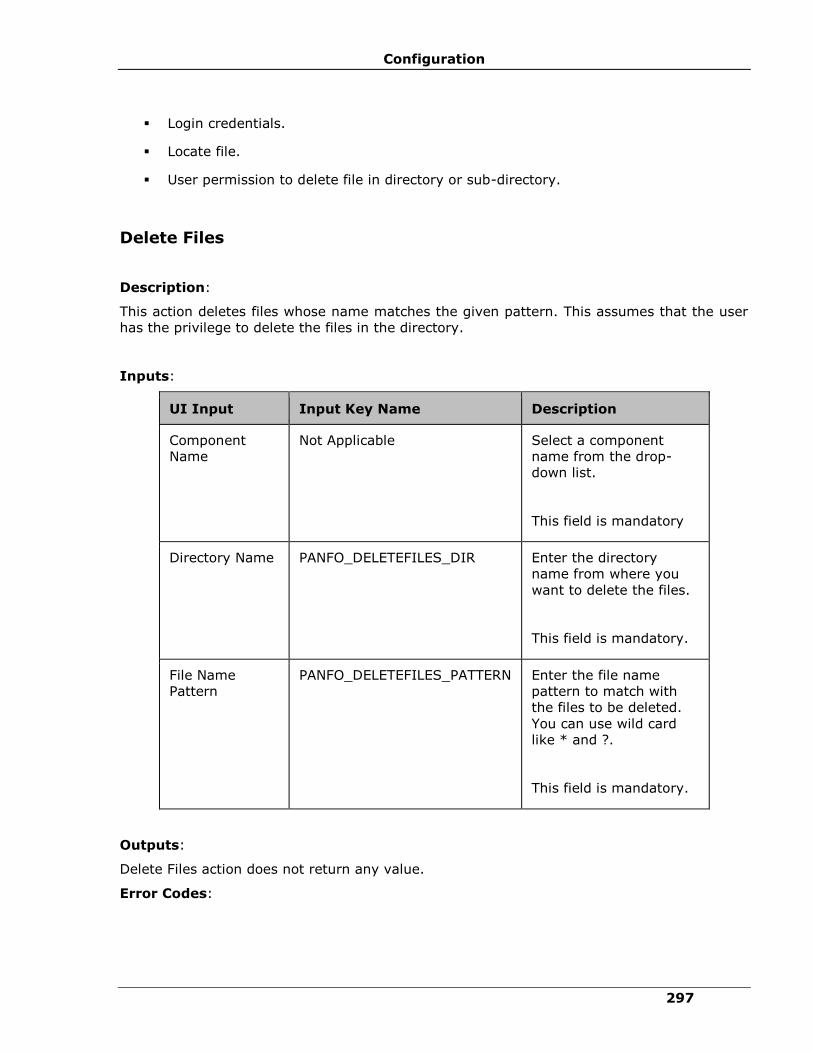
Configuration
297
▪ Login credentials.
▪ Locate file.
▪ User permission to delete file in directory or sub-directory.
Delete Files
Description:
This action deletes files whose name matches the given pattern. This assumes that the user
has the privilege to delete the files in the directory.
Inputs:
UI Input Input Key Name Description
Component
Name
Not Applicable
Select a component
name from the drop-
down list.
This field is mandatory
Directory Name PANFO_DELETEFILES_DIR Enter the directory
name from where you
want to delete the files.
This field is mandatory.
File Name
Pattern
PANFO_DELETEFILES_PATTERN Enter the file name
pattern to match with
the files to be deleted.
You can use wild card
like * and ?.
This field is mandatory.
Outputs:
Delete Files action does not return any value.
Error Codes:
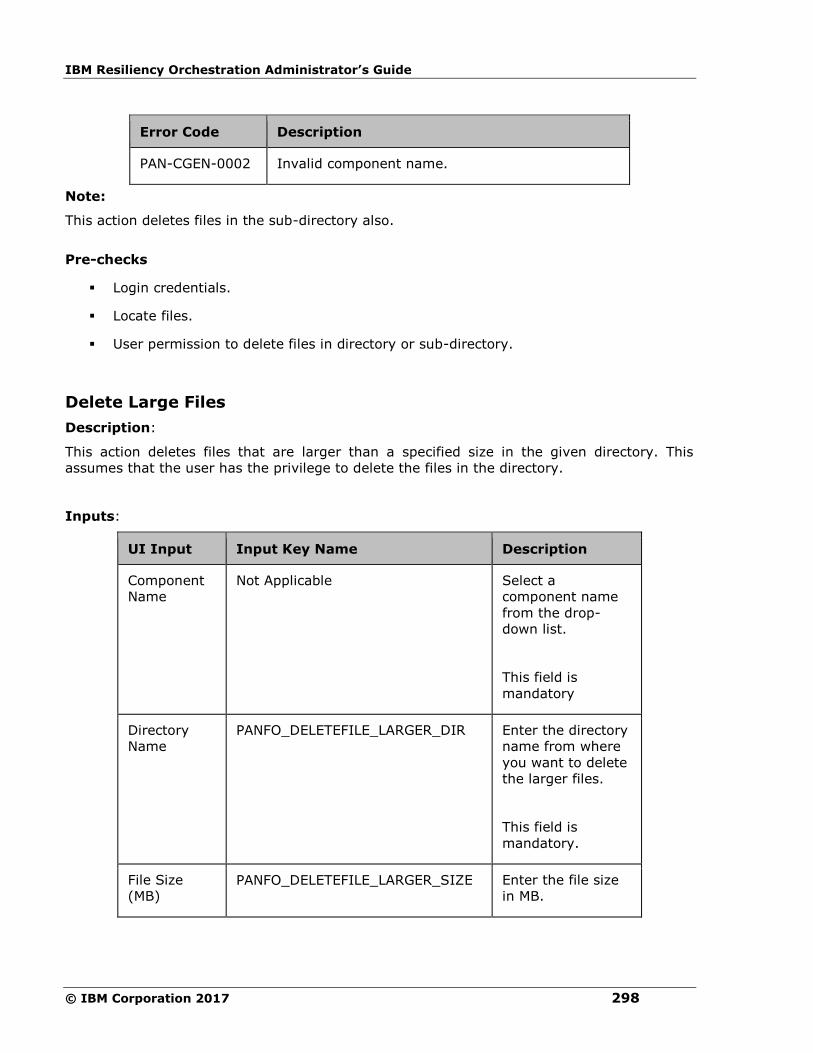
IBM Resiliency Orchestration Administrator’s Guide
© IBM Corporation 2017 298
Error Code Description
PAN-CGEN-0002 Invalid component name.
Note:
This action deletes files in the sub-directory also.
Pre-checks
▪ Login credentials.
▪ Locate files.
▪ User permission to delete files in directory or sub-directory.
Delete Large Files
Description:
This action deletes files that are larger than a specified size in the given directory. This
assumes that the user has the privilege to delete the files in the directory.
Inputs:
UI Input Input Key Name Description
Component
Name
Not Applicable
Select a
component name
from the drop-
down list.
This field is
mandatory
Directory
Name
PANFO_DELETEFILE_LARGER_DIR Enter the directory
name from where
you want to delete
the larger files.
This field is
mandatory.
File Size
(MB) PANFO_DELETEFILE_LARGER_SIZE Enter the file size
in MB.

Configuration
299
This field is
mandatory.
Note:
This action deletes files in the sub-directory also.
Outputs:
Delete Larger Files action does not return any value.
Error Codes:
Error Code Description
PAN-CGEN-0002 Invalid component name.
Note:
This action deletes files in the sub-directory also.
Pre-checks
▪ Login credentials.
▪ Locate file.
▪ User permission to delete large files in directory or sub-directory.
Delete Old Files
Delete Old Files - Deletes files that are older than the specified period.
Description:
This action deletes files that are older than the specified period in the given directory. This
assumes that the user has the privilege to delete the files in the directory.
Inputs:
UI Input Input Key Name Description
Component
Name
Not Applicable Select a component
name from the drop-
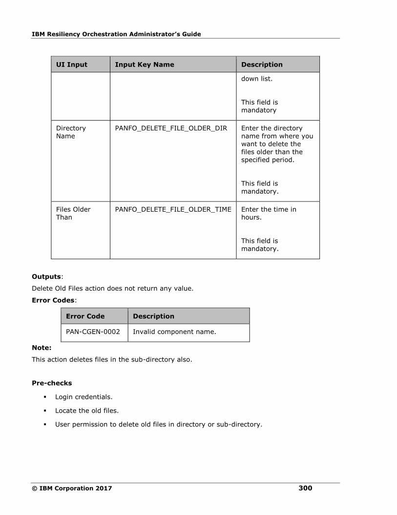
IBM Resiliency Orchestration Administrator’s Guide
© IBM Corporation 2017 300
UI Input Input Key Name Description
down list.
This field is
mandatory
Directory
Name
PANFO_DELETE_FILE_OLDER_DIR Enter the directory
name from where you
want to delete the
files older than the
specified period.
This field is
mandatory.
Files Older
Than
PANFO_DELETE_FILE_OLDER_TIME Enter the time in
hours.
This field is
mandatory.
Outputs:
Delete Old Files action does not return any value.
Error Codes:
Error Code Description
PAN-CGEN-0002 Invalid component name.
Note:
This action deletes files in the sub-directory also.
Pre-checks
▪ Login credentials.
▪ Locate the old files.
▪ User permission to delete old files in directory or sub-directory.
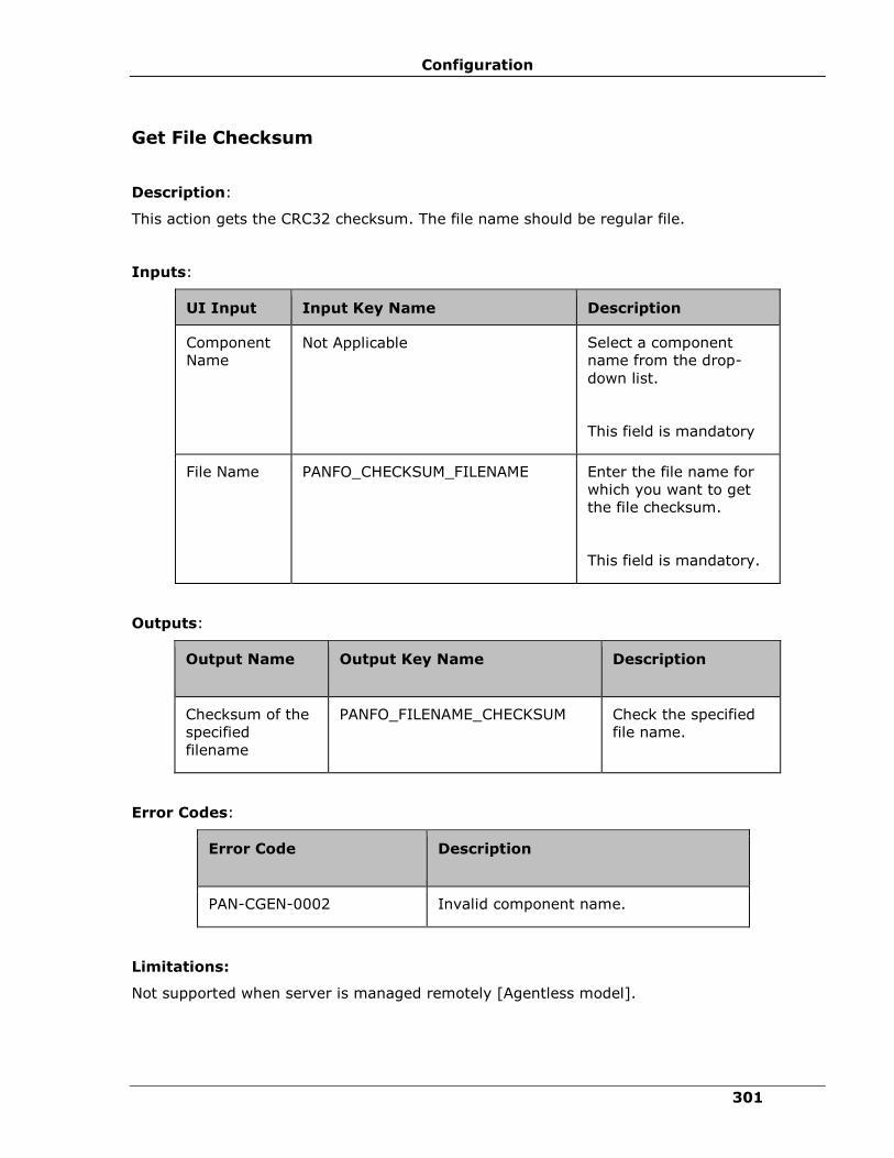
Configuration
301
Get File Checksum
Description:
This action gets the CRC32 checksum. The file name should be regular file.
Inputs:
UI Input Input Key Name Description
Component
Name Not Applicable
Select a component
name from the drop-
down list.
This field is mandatory
File Name
PANFO_CHECKSUM_FILENAME
Enter the file name for
which you want to get
the file checksum.
This field is mandatory.
Outputs:
Output Name Output Key Name
Description
Checksum of the
specified
filename
PANFO_FILENAME_CHECKSUM
Check the specified
file name.
Error Codes:
Error Code Description
PAN-CGEN-0002 Invalid component name.
Limitations:
Not supported when server is managed remotely [Agentless model].
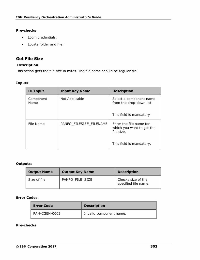
IBM Resiliency Orchestration Administrator’s Guide
© IBM Corporation 2017 302
Pre-checks
▪ Login credentials.
▪ Locate folder and file.
Get File Size
Description:
This action gets the file size in bytes. The file name should be regular file.
Inputs:
UI Input Input Key Name Description
Component
Name
Not Applicable
Select a component name
from the drop-down list.
This field is mandatory
File Name PANFO_FILESIZE_FILENAME Enter the file name for
which you want to get the
file size.
This field is mandatory.
Outputs:
Output Name Output Key Name Description
Size of file PANFO_FILE_SIZE Checks size of the
specified file name.
Error Codes:
Error Code Description
PAN-CGEN-0002 Invalid component name.
Pre-checks

Configuration
303
▪ Login credentials.
▪ Locate file within the prescribed folder on a selected machine.
Get File Time
Description:
This action gets the timestamp of the file. The file name should be regular file.
Inputs:
UI Input Input Key Name Description
Component
Name
Not Applicable
Select a component
name from the drop-
down list.
This field is
mandatory
File Name PANFO_TIMESTAMP_FILENAME Enter the file name
for which you want to
get the timestamp.
This field is
mandatory.
Outputs:
Output Name Output Key Name Description
Timestamp of file PANFO_FILE_TIMESTAMP Gets the timestamp of
the file.
Error Codes:
Error Code Description
PAN-CGEN-0002 Invalid component name.
Pre-checks

IBM Resiliency Orchestration Administrator’s Guide
© IBM Corporation 2017 304
▪ Login credentials.
▪ Locate file within the prescribed folder on a selected machine.
Replace in a File
Description:
This action checks whether a specified pattern exists in the given file and if found replaces
with the replace text.
Inputs:
UI Input Input Key Name Description
Component Name Not Applicable Select a
component
name from the
drop-down list.
This field is
mandatory
File name PANFO_REPLACE_FILE_TEXT_DIR Enter the file
name and path
for which you
want to replace
the text.
This field is
mandatory.
Pattern to search PANFO_REPLACE_FILE_TEXT_PATTERN Enter the text
that you want to
search in the
specified file.
This field is
mandatory.
Replacement Text PANFO_REPLACE_FILE_TEXT Enter the text
that you to
replace with the

Configuration
305
UI Input Input Key Name Description
existing
specified text.
This field is
mandatory.
Outputs:
Replace in a File action does not return any value.
Error Codes:
Error Code Description
PAN-CGEN-0002 Invalid component name.
Limitations:
Not supported when server is managed remotely [Agentless model].
Pre-checks
▪ Login credentials.
▪ User permission to access the folder and edit the file.
▪ Locate file in the directory or sub-directory.
Search in a File
Description:
This action checks whether a specified pattern exists in the given file or not.
Inputs:
UI Input Input Key Name Description
Component Not Applicable Select a component
name from the
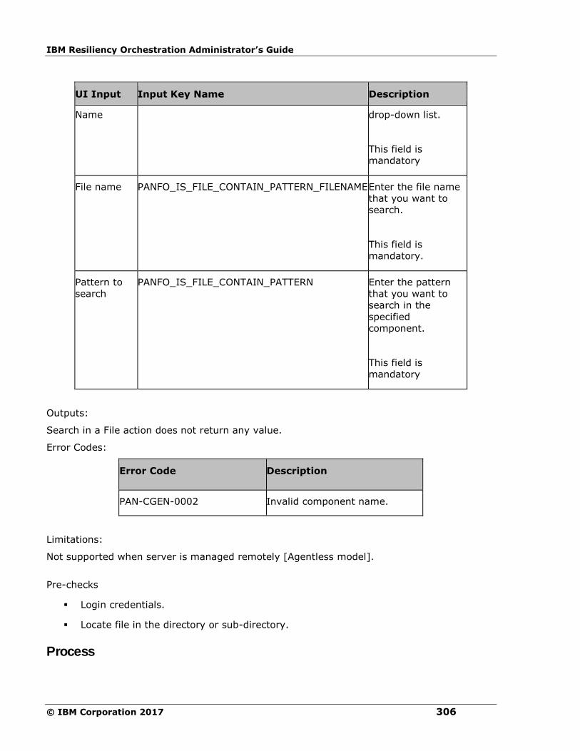
IBM Resiliency Orchestration Administrator’s Guide
© IBM Corporation 2017 306
UI Input Input Key Name Description
Name drop-down list.
This field is
mandatory
File name PANFO_IS_FILE_CONTAIN_PATTERN_FILENAME Enter the file name
that you want to
search.
This field is
mandatory.
Pattern to
search
PANFO_IS_FILE_CONTAIN_PATTERN Enter the pattern
that you want to
search in the
specified
component.
This field is
mandatory
Outputs:
Search in a File action does not return any value.
Error Codes:
Error Code Description
PAN-CGEN-0002 Invalid component name.
Limitations:
Not supported when server is managed remotely [Agentless model].
Pre-checks
▪ Login credentials.
▪ Locate file in the directory or sub-directory.
Process

Configuration
307
Check Port in Use
Check Port in Use - Checks whether a particular communication port is in use.
Description:
This action checks whether a particular communication port is in use. This can be used to
check whether an application has successfully started or not.
Inputs:
UI Input Input Key Name Description
Component
Name
Not Applicable Select the component name
from the drop-down list.
Port Number PANOS_CHECK_PORT Enter the port number.
This field is mandatory.
Outputs:
Output
Name Output Key Name Description
Process
Found
PANOS_CHECK_PORT_RESULT The output of this
action will be a boolean
value - 'true' if the port
is in use, else 'false'.
Note:
▪ The OS agent needs to run with root/Administrator privileges for the proper output for
ports requiring privileged access.
▪ In MS-Windows platform, OS agent running as "Local System Account" will inherit the
security policy of the "Default User"(not the "Current User") and by default provides
no-barred access to all the ports and the result provided by this method may be
wrong. It is advised to run the OS agent as service under a user-defined
account.(Refer http://technet.microsoft.com/en-us/magazine/cc162523.aspx for more
details).
Error Codes:
Error Code Description
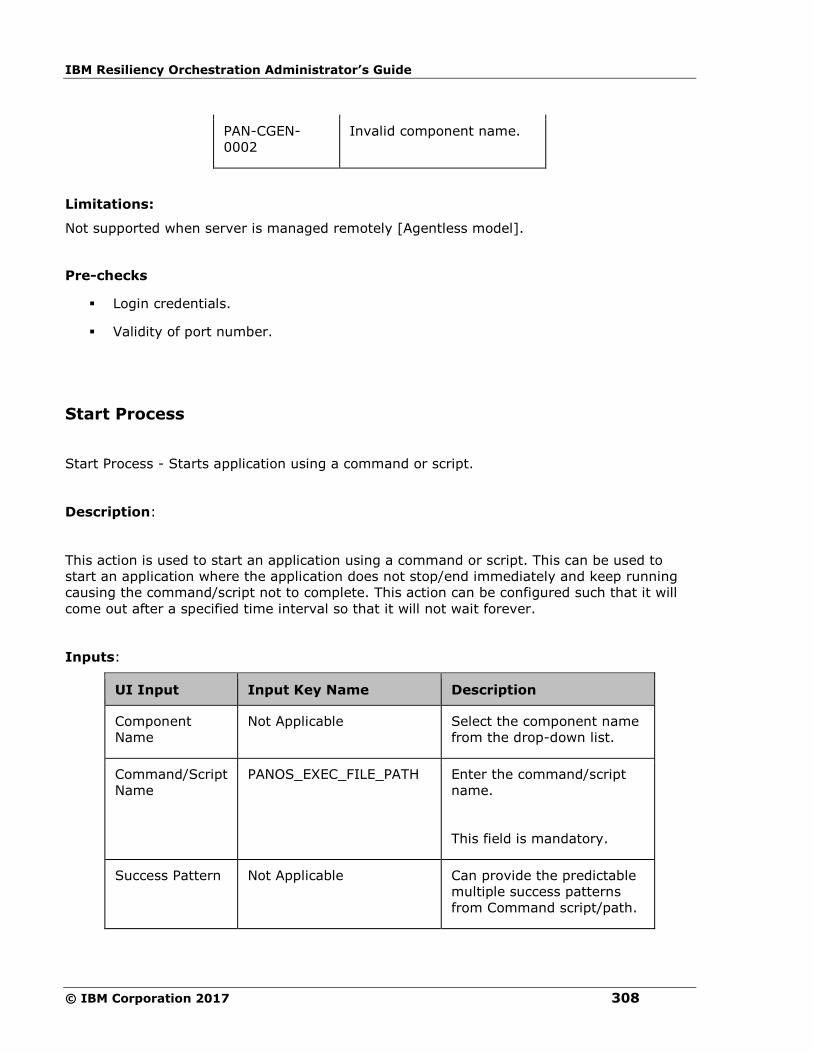
IBM Resiliency Orchestration Administrator’s Guide
© IBM Corporation 2017 308
PAN-CGEN-
0002
Invalid component name.
Limitations:
Not supported when server is managed remotely [Agentless model].
Pre-checks
▪ Login credentials.
▪ Validity of port number.
Start Process
Start Process - Starts application using a command or script.
Description:
This action is used to start an application using a command or script. This can be used to
start an application where the application does not stop/end immediately and keep running
causing the command/script not to complete. This action can be configured such that it will
come out after a specified time interval so that it will not wait forever.
Inputs:
UI Input Input Key Name Description
Component
Name
Not Applicable Select the component name
from the drop-down list.
Command/Script
Name
PANOS_EXEC_FILE_PATH Enter the command/script
name.
This field is mandatory.
Success Pattern Not Applicable Can provide the predictable
multiple success patterns
from Command script/path.
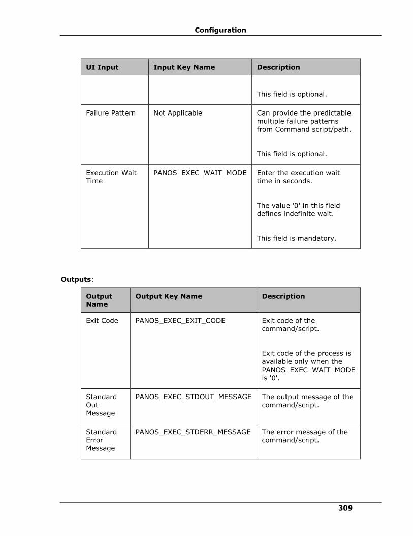
Configuration
309
UI Input Input Key Name Description
This field is optional.
Failure Pattern Not Applicable Can provide the predictable
multiple failure patterns
from Command script/path.
This field is optional.
Execution Wait
Time
PANOS_EXEC_WAIT_MODE Enter the execution wait
time in seconds.
The value '0' in this field
defines indefinite wait.
This field is mandatory.
Outputs:
Output
Name
Output Key Name Description
Exit Code PANOS_EXEC_EXIT_CODE Exit code of the
command/script.
Exit code of the process is
available only when the
PANOS_EXEC_WAIT_MODE
is '0'.
Standard
Out
Message
PANOS_EXEC_STDOUT_MESSAGE The output message of the
command/script.
Standard
Error
Message
PANOS_EXEC_STDERR_MESSAGE The error message of the
command/script.
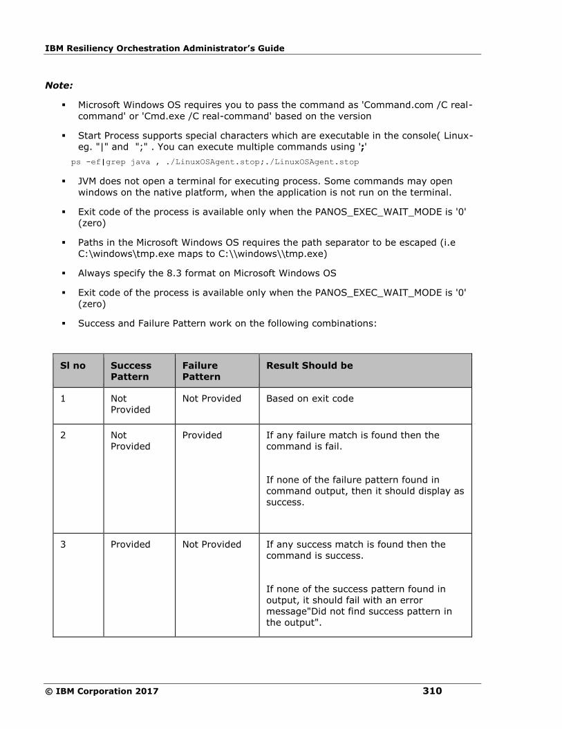
IBM Resiliency Orchestration Administrator’s Guide
© IBM Corporation 2017 310
Note:
▪ Microsoft Windows OS requires you to pass the command as 'Command.com /C real-
command' or 'Cmd.exe /C real-command' based on the version
▪ Start Process supports special characters which are executable in the console( Linux-
eg. "|" and ";" . You can execute multiple commands using ';'
ps -ef|grep java , ./LinuxOSAgent.stop;./LinuxOSAgent.stop
▪ JVM does not open a terminal for executing process. Some commands may open
windows on the native platform, when the application is not run on the terminal.
▪ Exit code of the process is available only when the PANOS_EXEC_WAIT_MODE is '0'
(zero)
▪ Paths in the Microsoft Windows OS requires the path separator to be escaped (i.e
C:\windows\tmp.exe maps to C:\\windows\\tmp.exe)
▪ Always specify the 8.3 format on Microsoft Windows OS
▪ Exit code of the process is available only when the PANOS_EXEC_WAIT_MODE is '0'
(zero)
▪ Success and Failure Pattern work on the following combinations:
Sl no Success
Pattern
Failure
Pattern
Result Should be
1 Not
Provided
Not Provided Based on exit code
2 Not
Provided
Provided If any failure match is found then the
command is fail.
If none of the failure pattern found in
command output, then it should display as
success.
3 Provided Not Provided If any success match is found then the
command is success.
If none of the success pattern found in
output, it should fail with an error
message"Did not find success pattern in
the output".

Configuration
311
4 Provided Provided Firstly, the failure patterns is matched; if
match is found, then command is fail.
If none of the failure pattern is found then
success pattern is matched; if match is
found, then command is success.
If none of the patterns are found in the
output:
An error message "Did not find success
pattern in the output" is displayed.
Note:
If multiple Success or Multiple Failure patterns are configured, then the output is dependent
on EITHER the first Failure/Success pattern OR second Failure/Success pattern OR third
Failure/Success pattern etc.
Error Codes:
Error Code Description
PAN-CGEN-0002 Invalid component
name.
Pre-checks
▪ Login credentials.
▪ Command or script is available on the machines.
▪ Command for Windows and the configured script path is the correct format for IBM
Resiliency Orchestration.
▪ User permission to start the process.
Find Process
Find Process - Checks whether a particular application/process is running by checking it's
name against the names of the active application/process.
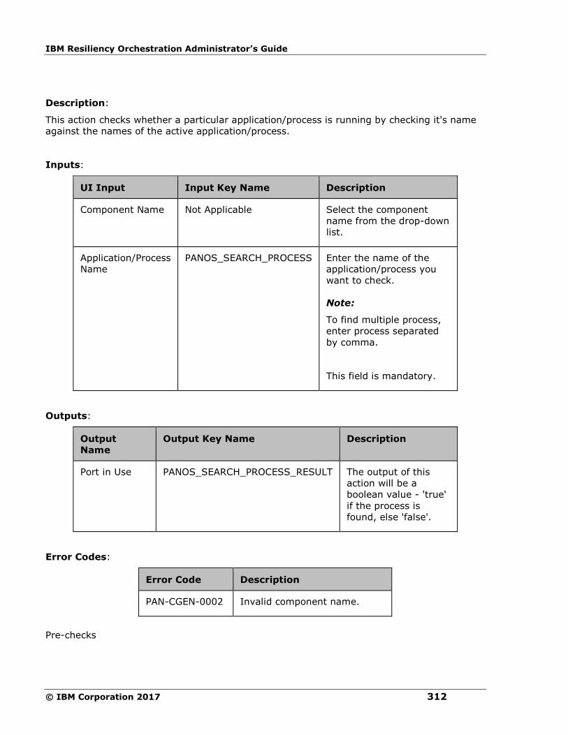
IBM Resiliency Orchestration Administrator’s Guide
© IBM Corporation 2017 312
Description:
This action checks whether a particular application/process is running by checking it's name
against the names of the active application/process.
Inputs:
UI Input Input Key Name Description
Component Name Not Applicable Select the component
name from the drop-down
list.
Application/Process
Name
PANOS_SEARCH_PROCESS Enter the name of the
application/process you
want to check.
Note:
To find multiple process,
enter process separated
by comma.
This field is mandatory.
Outputs:
Output
Name
Output Key Name Description
Port in Use PANOS_SEARCH_PROCESS_RESULT The output of this
action will be a
boolean value - 'true'
if the process is
found, else 'false'.
Error Codes:
Error Code Description
PAN-CGEN-0002 Invalid component name.
Pre-checks

Configuration
313
▪ Login credentials.
▪ Process is running on the machines.
Repeatable
Repeatable
Repeatable Actions/Add new Action to RAL catalogue
1. Add provision in CLI to create new action
2. Provide name and category ( with in Custom RAL’s)
3. Provide the command/script and its dependencies
It will be added to the custom RAL library
4. Add it to the workflow, the configured values are prefilled.
Execution will be similar to custom action.
Scripts should be copied to
{EAMSROOT}/scripts/repeatable/{category Name}/{Action Name}/{scripts and its
depended files}
Ex:
/opt/panaces/scripts/repeatable/checkStatus/checkStatus/ping.sh
/opt/panaces/scripts/repeatable/checkStatus/checkStatus /pingdep.sh
This has to be repeated for all the agents using this RAL and server.
To Edit Repeatable RAL:
Limitation:
1. On Adding RAL the first time we need to open the Action property before publishing.
2. Refresh is not allowed after adding RAL. (Script in Action property will go off).
In UI
1. Go to workflow Editor >Add >Action
2. Select Action Category >Add Action in Workflow and Execute
Replication Level

IBM Resiliency Orchestration Administrator’s Guide
© IBM Corporation 2017 314
EMC BCV
establishBCV
This action re-establishes BCV devices to its RDF devices. If this is done successfully, all the
changes done on the RDF devices starts getting updated on the BCV devices.
Once the resync request is initiated,this action gets completed without waiting for completion
of resynchronization. 'getBCVStatus' or 'verifyBCVStatus' action should be used to check if
the pair has arrived to a particular state. This action provides an option to select 'full
establish'. If the user has selected "Full" mode, then full establish will be performed.
This operation can also be forced by selecting 'forceful'. When the 'force' option is used,
SYMCLI attempts to force the operation even though one or more devices in the device group
may not be in the normal, expected BCV state or mode for the operation.
When this action is executed as a part of workflow, the SYMCLI 'symmir establish' command
is invoked on the pair represented by the selected protection scheme, along the appropriate
options selected by the user.
Inputs:
UI Input Description Input Key Name Key
Values
Input
Optional/
Mandatory
Protection
Scheme
Name
Select the
protection
scheme
name
configured
for the
group from
the drop-
down list.
Note:
If the group
is attached
with more
than one
pair of
protection
subsystem
then do not
select
"Current
Production
Service" or
EMC_ESTABLISH_BCV_OPER_ON - Mandatory
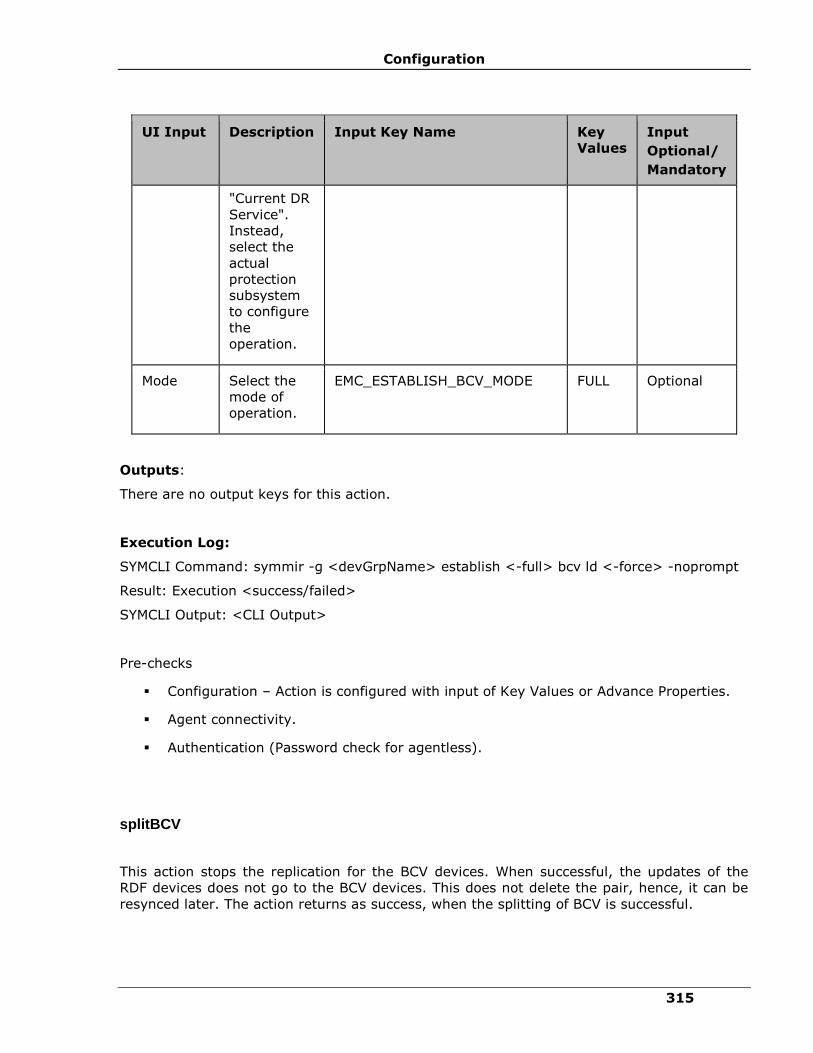
Configuration
315
UI Input Description Input Key Name Key
Values
Input
Optional/
Mandatory
"Current DR
Service".
Instead,
select the
actual
protection
subsystem
to configure
the
operation.
Mode Select the
mode of
operation.
EMC_ESTABLISH_BCV_MODE FULL Optional
Outputs:
There are no output keys for this action.
Execution Log:
SYMCLI Command: symmir -g <devGrpName> establish <-full> bcv ld <-force> -noprompt
Result: Execution <success/failed>
SYMCLI Output: <CLI Output>
Pre-checks
▪ Configuration – Action is configured with input of Key Values or Advance Properties.
▪ Agent connectivity.
▪ Authentication (Password check for agentless).
splitBCV
This action stops the replication for the BCV devices. When successful, the updates of the
RDF devices does not go to the BCV devices. This does not delete the pair, hence, it can be
resynced later. The action returns as success, when the splitting of BCV is successful.
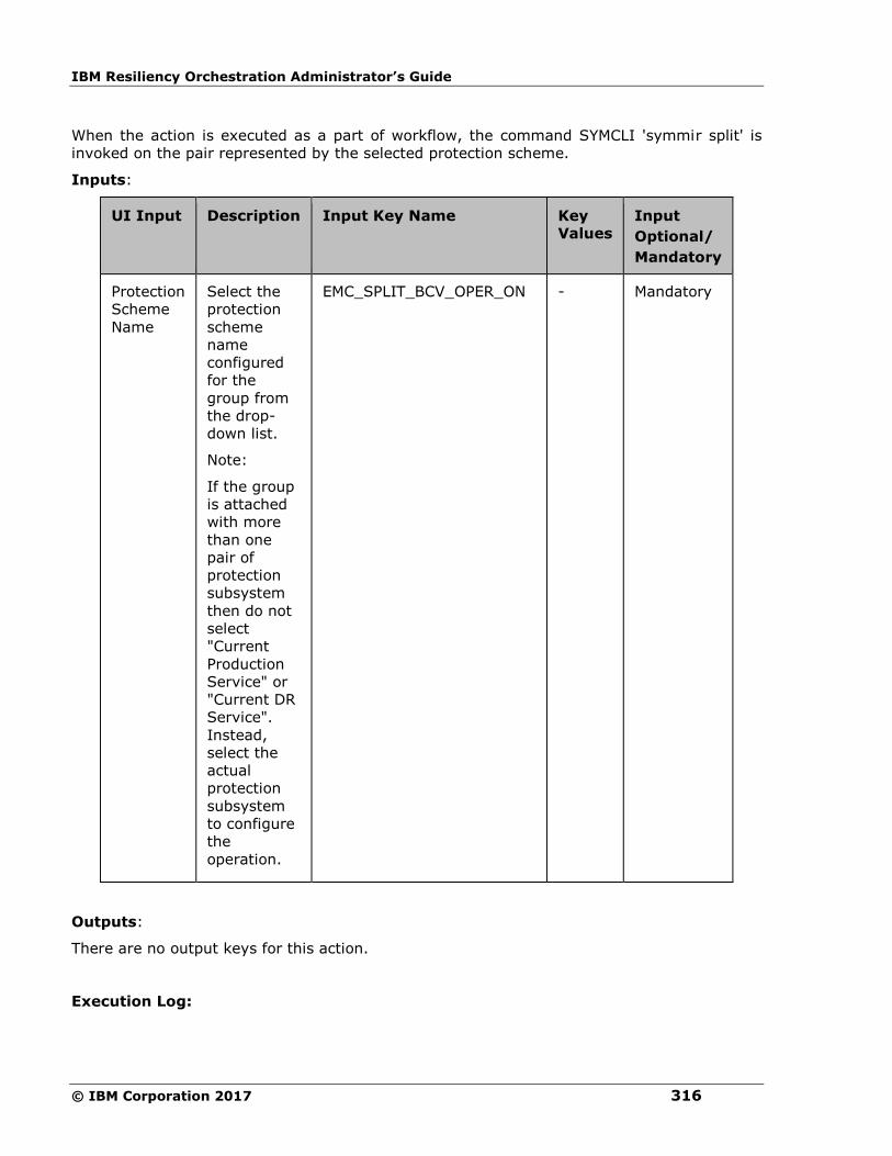
IBM Resiliency Orchestration Administrator’s Guide
© IBM Corporation 2017 316
When the action is executed as a part of workflow, the command SYMCLI 'symmir split' is
invoked on the pair represented by the selected protection scheme.
Inputs:
UI Input Description Input Key Name
Key
Values
Input
Optional/
Mandatory
Protection
Scheme
Name
Select the
protection
scheme
name
configured
for the
group from
the drop-
down list.
Note:
If the group
is attached
with more
than one
pair of
protection
subsystem
then do not
select
"Current
Production
Service" or
"Current DR
Service".
Instead,
select the
actual
protection
subsystem
to configure
the
operation.
EMC_SPLIT_BCV_OPER_ON - Mandatory
Outputs:
There are no output keys for this action.
Execution Log:
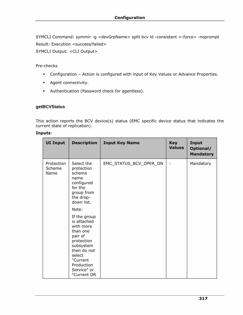
Configuration
317
SYMCLI Command: symmir -g <devGrpName> split bcv ld -consistent <-force> -noprompt
Result: Execution <success/failed>
SYMCLI Output: <CLI Output>
Pre-checks
▪ Configuration – Action is configured with input of Key Values or Advance Properties.
▪ Agent connectivity.
▪ Authentication (Password check for agentless).
getBCVStatus
This action reports the BCV device(s) status (EMC specific device status that indicates the
current state of replication).
Inputs:
UI Input Description Input Key Name
Key
Values
Input
Optional/
Mandatory
Protection
Scheme
Name
Select the
protection
scheme
name
configured
for the
group from
the drop-
down list.
Note:
If the group
is attached
with more
than one
pair of
protection
subsystem
then do not
select
"Current
Production
Service" or
"Current DR
EMC_STATUS_BCV_OPER_ON - Mandatory
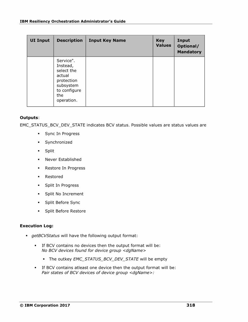
IBM Resiliency Orchestration Administrator’s Guide
© IBM Corporation 2017 318
UI Input Description Input Key Name
Key
Values
Input
Optional/
Mandatory
Service".
Instead,
select the
actual
protection
subsystem
to configure
the
operation.
Outputs:
EMC_STATUS_BCV_DEV_STATE indicates BCV status. Possible values are status values are
▪ Sync In Progress
▪ Synchronized
▪ Split
▪ Never Established
▪ Restore In Progress
▪ Restored
▪ Split In Progress
▪ Split No Increment
▪ Split Before Sync
▪ Split Before Restore
Execution Log:
▪ getBCVStatus will have the following output format:
▪ If BCV contains no devices then the output format will be:
No BCV devices found for device group <dgName>
▪ The outkey EMC_STATUS_BCV_DEV_STATE will be empty
▪ If BCV contains atleast one device then the output format will be:
Pair states of BCV devices of device group <dgName>:
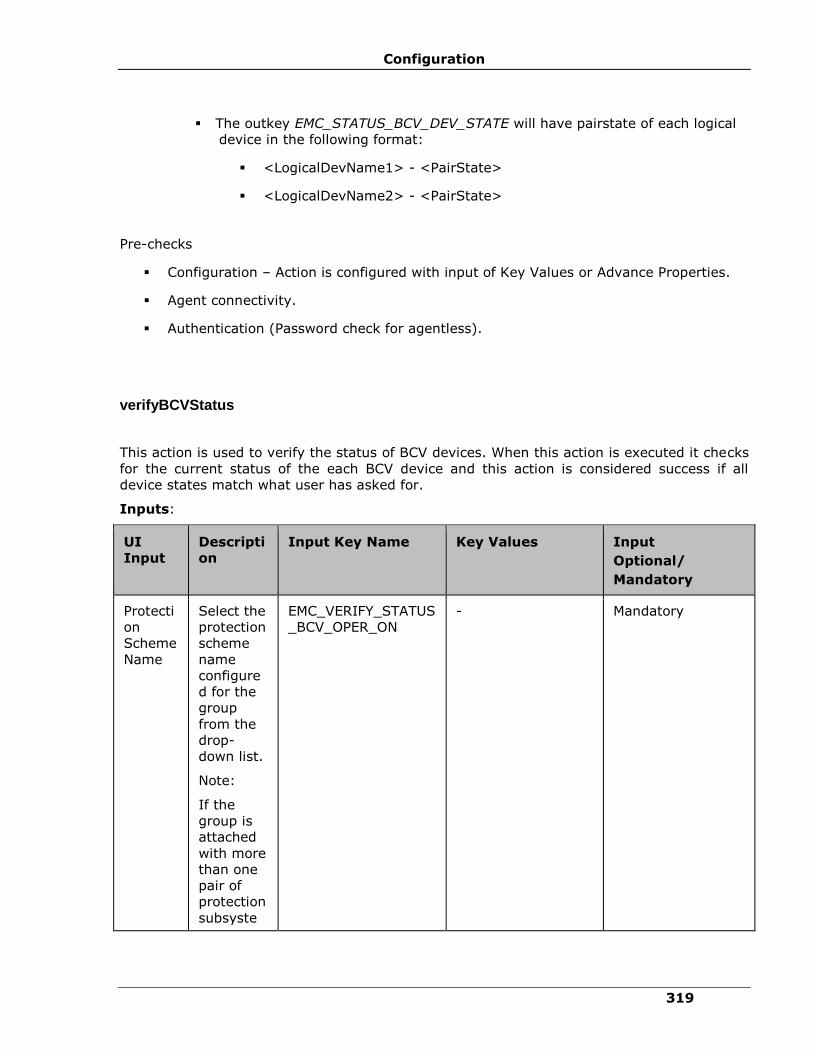
Configuration
319
▪ The outkey EMC_STATUS_BCV_DEV_STATE will have pairstate of each logical
device in the following format:
▪ <LogicalDevName1> - <PairState>
▪ <LogicalDevName2> - <PairState>
Pre-checks
▪ Configuration – Action is configured with input of Key Values or Advance Properties.
▪ Agent connectivity.
▪ Authentication (Password check for agentless).
verifyBCVStatus
This action is used to verify the status of BCV devices. When this action is executed it checks
for the current status of the each BCV device and this action is considered success if all
device states match what user has asked for.
Inputs:
UI
Input
Descripti
on
Input Key Name
Key Values Input
Optional/
Mandatory
Protecti
on
Scheme
Name
Select the
protection
scheme
name
configure
d for the
group
from the
drop-
down list.
Note:
If the
group is
attached
with more
than one
pair of
protection
subsyste
EMC_VERIFY_STATUS
_BCV_OPER_ON
- Mandatory
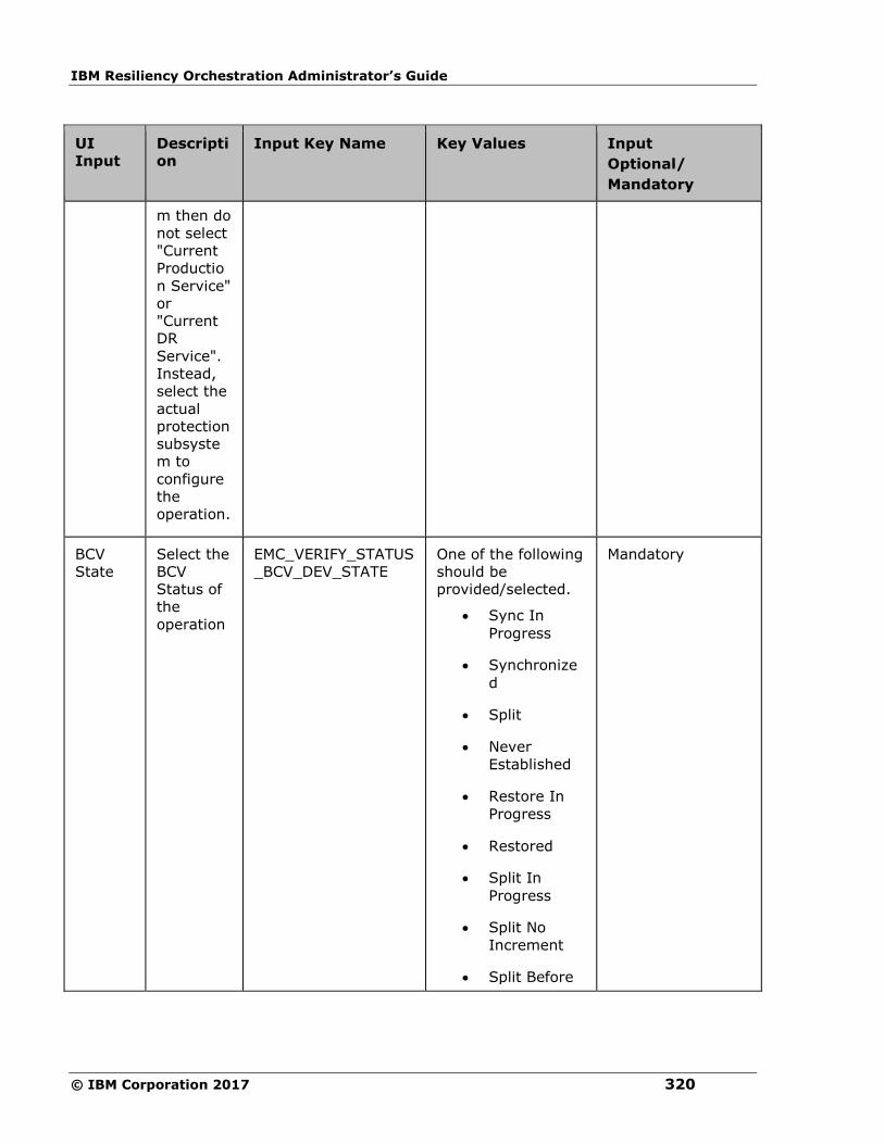
IBM Resiliency Orchestration Administrator’s Guide
© IBM Corporation 2017 320
UI
Input
Descripti
on
Input Key Name
Key Values Input
Optional/
Mandatory
m then do
not select
"Current
Productio
n Service"
or
"Current
DR
Service".
Instead,
select the
actual
protection
subsyste
m to
configure
the
operation.
BCV
State
Select the
BCV
Status of
the
operation
EMC_VERIFY_STATUS
_BCV_DEV_STATE
One of the following
should be
provided/selected.
• Sync In
Progress
• Synchronize
d
• Split
• Never
Established
• Restore In
Progress
• Restored
• Split In
Progress
• Split No
Increment
• Split Before
Mandatory
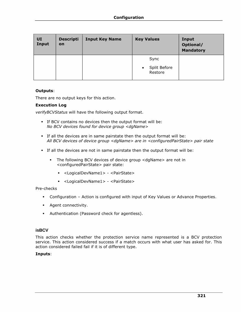
Configuration
321
UI
Input
Descripti
on
Input Key Name
Key Values Input
Optional/
Mandatory
Sync
• Split Before
Restore
Outputs:
There are no output keys for this action.
Execution Log
verifyBCVStatus will have the following output format.
▪ If BCV contains no devices then the output format will be:
No BCV devices found for device group <dgName>
▪ If all the devices are in same pairstate then the output format will be:
All BCV devices of device group <dgName> are in <configuredPairState> pair state
▪ If all the devices are not in same pairstate then the output format will be:
▪ The following BCV devices of device group <dgName> are not in
<configuredPairState> pair state:
▪ <LogicalDevName1> - <PairState>
▪ <LogicalDevName1> - <PairState>
Pre-checks
▪ Configuration – Action is configured with input of Key Values or Advance Properties.
▪ Agent connectivity.
▪ Authentication (Password check for agentless).
isBCV
This action checks whether the protection service name represented is a BCV protection
service. This action considered success if a match occurs with what user has asked for. This
action considered failed fail if it is of different type.
Inputs:
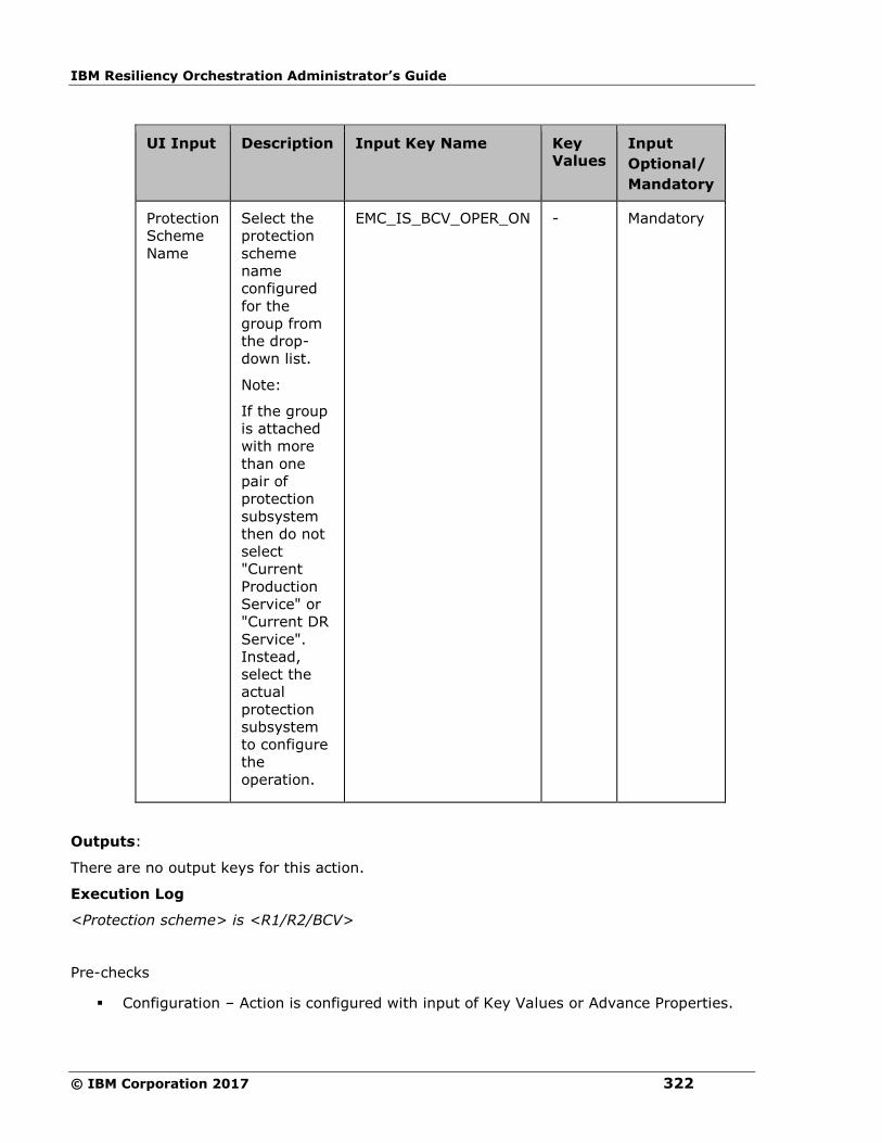
IBM Resiliency Orchestration Administrator’s Guide
© IBM Corporation 2017 322
UI Input Description Input Key Name
Key
Values
Input
Optional/
Mandatory
Protection
Scheme
Name
Select the
protection
scheme
name
configured
for the
group from
the drop-
down list.
Note:
If the group
is attached
with more
than one
pair of
protection
subsystem
then do not
select
"Current
Production
Service" or
"Current DR
Service".
Instead,
select the
actual
protection
subsystem
to configure
the
operation.
EMC_IS_BCV_OPER_ON - Mandatory
Outputs:
There are no output keys for this action.
Execution Log
<Protection scheme> is <R1/R2/BCV>
Pre-checks
▪ Configuration – Action is configured with input of Key Values or Advance Properties.
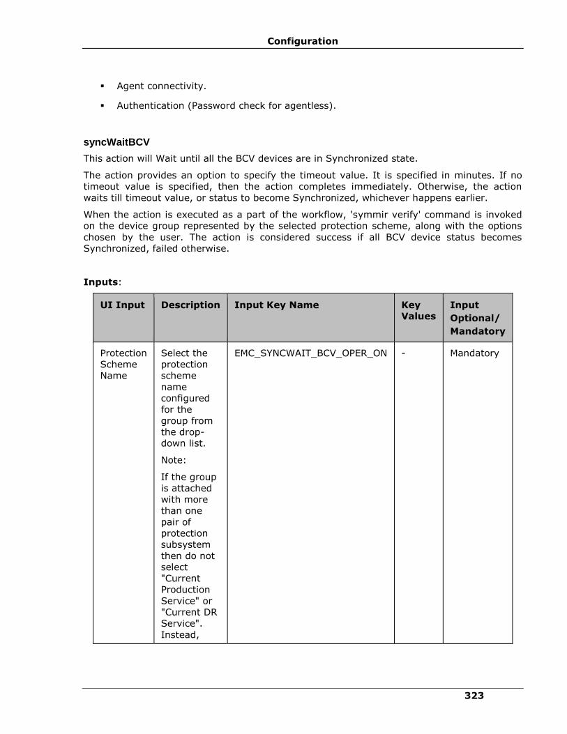
Configuration
323
▪ Agent connectivity.
▪ Authentication (Password check for agentless).
syncWaitBCV
This action will Wait until all the BCV devices are in Synchronized state.
The action provides an option to specify the timeout value. It is specified in minutes. If no
timeout value is specified, then the action completes immediately. Otherwise, the action
waits till timeout value, or status to become Synchronized, whichever happens earlier.
When the action is executed as a part of the workflow, 'symmir verify' command is invoked
on the device group represented by the selected protection scheme, along with the options
chosen by the user. The action is considered success if all BCV device status becomes
Synchronized, failed otherwise.
Inputs:
UI Input Description Input Key Name
Key
Values
Input
Optional/
Mandatory
Protection
Scheme
Name
Select the
protection
scheme
name
configured
for the
group from
the drop-
down list.
Note:
If the group
is attached
with more
than one
pair of
protection
subsystem
then do not
select
"Current
Production
Service" or
"Current DR
Service".
Instead,
EMC_SYNCWAIT_BCV_OPER_ON - Mandatory

IBM Resiliency Orchestration Administrator’s Guide
© IBM Corporation 2017 324
UI Input Description Input Key Name
Key
Values
Input
Optional/
Mandatory
select the
actual
protection
subsystem
to configure
the
operation.
BCV
State
Zero will
verify once,
any other
positive
integer will
verify every
30 seconds
EMC_SYNCWAIT_BCV_TIMEOUT 0 or
more (
by
default
it is 0).
Optional
Outputs:
There are no output keys for this action.
Pre-checks
▪ Configuration – Action is configured with input of Key Values or Advance Properties.
▪ Agent connectivity.
▪ Authentication (Password check for agentless).
EMC Clone
Recreate Clone
Description:
This action creates an internal copy session with the devices in the device group and one or
more target devices associated with the group. While the operation is in progress, the state
of the device pair is 'CreateInProgress'. When the operation completes, the state of the
device pair changes to 'Created'.
Inputs:

Configuration
325
Input
Name
Input
Type
Input Key Name Optional/
Mandatory
Operation
on
Choose
from the
list of
protection
schemes
configured
for the
group
EMC_RECREATE_CLONE_OPER_ON (
Production Protection Scheme or DR
Protection Scheme or service name),
EMC_RECREATE_CLONE_OPER_ON_TYPE
(DYNAMIC or STATIC)
Mandatory
rdf option Performs
the action
on the
remote
Symmetrix
array
EMC_RECREATE_CLONE_RDF Optional
tgt option Uses TGT
devices as
clone
targets.
When
used with
the -rdf
option, the
operation
will use
RTGT
devices
EMC_RECREATE_CLONE_TGT Optional
Outputs:
There are no output keys for this action.
Execution Log:
SYMCLI Command: symclone -g <devGrpName> recreate –precopy <-force> <-tgt> <-
rdf> -noprompt
Result: Execution <success/failed>
SYMCLI Output: <CLI Output>
Pre-checks
▪ Configuration – Action is configured with input of Key Values or Advance Properties.

IBM Resiliency Orchestration Administrator’s Guide
© IBM Corporation 2017 326
▪ Agent connectivity.
▪ Authentication (Password check for agentless).
Activate Clone
Description:
Activates an internal copy session with the devices in the device or composite group and one
or more target devices associated with the group.
While the operation is in progress, the state of the device pair is either CopyInProgress or
CopyOnAccess. When the operation completes, the state changes to Copied.
Inputs:
Input
Name
Input
Type
Input Key Name Optional/Mandatory
Operation
on
Choose
from the
list of
protection
scheme
configured
for the
group
EMC_RECREATE_CLONE_
OPER_ON
( Production Protection Scheme
or DR Protection Scheme
or service name),
EMC_RECREATE_CLONE_OPER_
ON_TYPE(DYNAMIC or STATIC)
Mandatory
rdf option Performs
the action
on the
remote
Symmetrix
array.
EMC_RECREATE_CLONE_RDF Optional
tgt option Uses TGT
devices as
clone
targets.
When used
with the -
rdf option,
the
operation
will use
RTGT
EMC_RECREATE_CLONE_TGT Optional
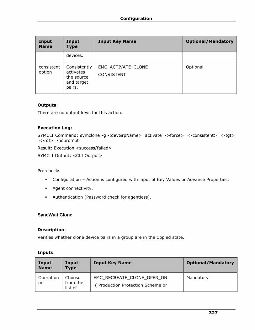
Configuration
327
Input
Name
Input
Type
Input Key Name Optional/Mandatory
devices.
consistent
option
Consistently
activates
the source
and target
pairs.
EMC_ACTIVATE_CLONE_
CONSISTENT
Optional
Outputs:
There are no output keys for this action.
Execution Log:
SYMCLI Command: symclone -g <devGrpName> activate <-force> <-consistent> <-tgt>
<-rdf> -noprompt
Result: Execution <success/failed>
SYMCLI Output: <CLI Output>
Pre-checks
▪ Configuration – Action is configured with input of Key Values or Advance Properties.
▪ Agent connectivity.
▪ Authentication (Password check for agentless).
SyncWait Clone
Description:
Verifies whether clone device pairs in a group are in the Copied state.
Inputs:
Input
Name
Input
Type
Input Key Name Optional/Mandatory
Operation
on
Choose
from the
list of
EMC_RECREATE_CLONE_OPER_ON
( Production Protection Scheme or
Mandatory
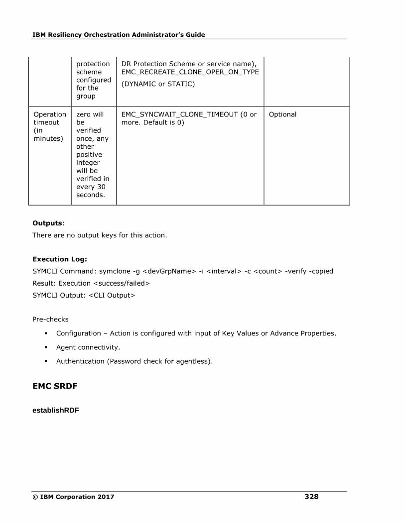
IBM Resiliency Orchestration Administrator’s Guide
© IBM Corporation 2017 328
protection
scheme
configured
for the
group
DR Protection Scheme or service name),
EMC_RECREATE_CLONE_OPER_ON_TYPE
(DYNAMIC or STATIC)
Operation
timeout
(in
minutes)
zero will
be
verified
once, any
other
positive
integer
will be
verified in
every 30
seconds.
EMC_SYNCWAIT_CLONE_TIMEOUT (0 or
more. Default is 0)
Optional
Outputs:
There are no output keys for this action.
Execution Log:
SYMCLI Command: symclone -g <devGrpName> -i <interval> -c <count> -verify -copied
Result: Execution <success/failed>
SYMCLI Output: <CLI Output>
Pre-checks
▪ Configuration – Action is configured with input of Key Values or Advance Properties.
▪ Agent connectivity.
▪ Authentication (Password check for agentless).
EMC SRDF
establishRDF
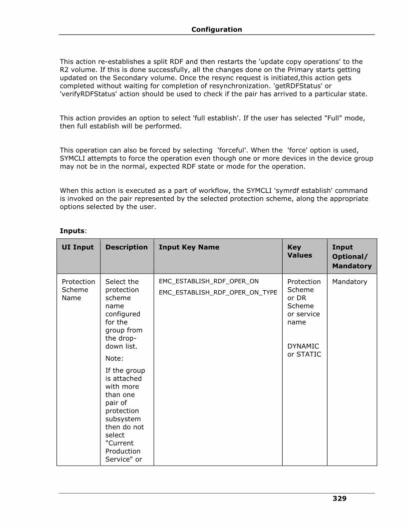
Configuration
329
This action re-establishes a split RDF and then restarts the 'update copy operations' to the
R2 volume. If this is done successfully, all the changes done on the Primary starts getting
updated on the Secondary volume. Once the resync request is initiated,this action gets
completed without waiting for completion of resynchronization. 'getRDFStatus' or
'verifyRDFStatus' action should be used to check if the pair has arrived to a particular state.
This action provides an option to select 'full establish'. If the user has selected "Full" mode,
then full establish will be performed.
This operation can also be forced by selecting 'forceful'. When the 'force' option is used,
SYMCLI attempts to force the operation even though one or more devices in the device group
may not be in the normal, expected RDF state or mode for the operation.
When this action is executed as a part of workflow, the SYMCLI 'symrdf establish' command
is invoked on the pair represented by the selected protection scheme, along the appropriate
options selected by the user.
Inputs:
UI Input Description Input Key Name
Key
Values
Input
Optional/
Mandatory
Protection
Scheme
Name
Select the
protection
scheme
name
configured
for the
group from
the drop-
down list.
Note:
If the group
is attached
with more
than one
pair of
protection
subsystem
then do not
select
"Current
Production
Service" or
EMC_ESTABLISH_RDF_OPER_ON
EMC_ESTABLISH_RDF_OPER_ON_TYPE
Protection
Scheme
or DR
Scheme
or service
name
DYNAMIC
or STATIC
Mandatory
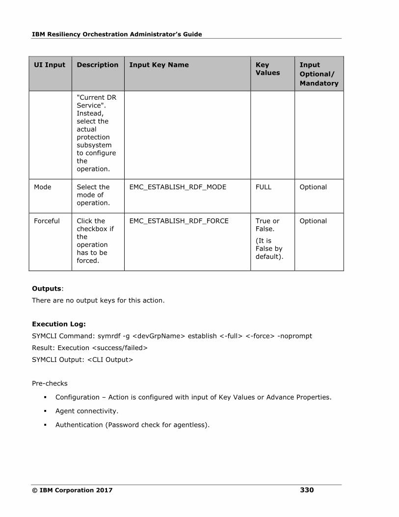
IBM Resiliency Orchestration Administrator’s Guide
© IBM Corporation 2017 330
UI Input Description Input Key Name
Key
Values
Input
Optional/
Mandatory
"Current DR
Service".
Instead,
select the
actual
protection
subsystem
to configure
the
operation.
Mode Select the
mode of
operation.
EMC_ESTABLISH_RDF_MODE FULL Optional
Forceful Click the
checkbox if
the
operation
has to be
forced.
EMC_ESTABLISH_RDF_FORCE True or
False.
(It is
False by
default).
Optional
Outputs:
There are no output keys for this action.
Execution Log:
SYMCLI Command: symrdf -g <devGrpName> establish <-full> <-force> -noprompt
Result: Execution <success/failed>
SYMCLI Output: <CLI Output>
Pre-checks
▪ Configuration – Action is configured with input of Key Values or Advance Properties.
▪ Agent connectivity.
▪ Authentication (Password check for agentless).
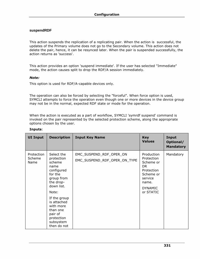
Configuration
331
suspendRDF
This action suspends the replication of a replicating pair. When the action is successful, the
updates of the Primary volume does not go to the Secondary volume. This action does not
delete the pair, hence, it can be resynced later. When the pair is suspended successfully, the
action returns as 'success'.
This action provides an option 'suspend immediate'. If the user has selected "Immediate"
mode, the action causes split to drop the RDF/A session immediately.
Note:
This option is used for RDF/A-capable devices only.
The operation can also be forced by selecting the "forceful". When force option is used,
SYMCLI attempts to force the operation even though one or more devices in the device group
may not be in the normal, expected RDF state or mode for the operation.
When the action is executed as a part of workflow, SYMCLI 'symrdf suspend' command is
invoked on the pair represented by the selected protection scheme, along the appropriate
options chosen by the user.
Inputs:
UI Input Description Input Key Name Key
Values
Input
Optional/
Mandatory
Protection
Scheme
Name
Select the
protection
scheme
name
configured
for the
group from
the drop-
down list.
Note:
If the group
is attached
with more
than one
pair of
protection
subsystem
then do not
EMC_SUSPEND_RDF_OPER_ON
EMC_SUSPEND_RDF_OPER_ON_TYPE
Production
Protection
Scheme or
DR
Protection
Scheme or
service
name.
DYNAMIC
or STATIC
Mandatory
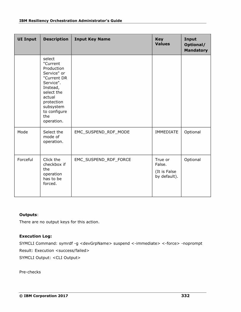
IBM Resiliency Orchestration Administrator’s Guide
© IBM Corporation 2017 332
UI Input Description Input Key Name Key
Values
Input
Optional/
Mandatory
select
"Current
Production
Service" or
"Current DR
Service".
Instead,
select the
actual
protection
subsystem
to configure
the
operation.
Mode Select the
mode of
operation.
EMC_SUSPEND_RDF_MODE IMMEDIATE Optional
Forceful Click the
checkbox if
the
operation
has to be
forced.
EMC_SUSPEND_RDF_FORCE True or
False.
(It is False
by default).
Optional
Outputs:
There are no output keys for this action.
Execution Log:
SYMCLI Command: symrdf -g <devGrpName> suspend <-immediate> <-force> -noprompt
Result: Execution <success/failed>
SYMCLI Output: <CLI Output>
Pre-checks

Configuration
333
▪ Configuration – Action is configured with input of Key Values or Advance Properties.
▪ Agent connectivity.
▪ Authentication (Password check for agentless).
resumeRDF
This action resumes a suspended RDF and then restarts the update copy operations to the R2
volume. If successful, all the changes done on the Primary starts getting updated on the
Secondary volume. The action completes after initiating the resync request and does not wait
for the resynchronization to complete. 'getRDFStatus' or 'verifyRDFStatus' action should be
used to check if the pair has arrived to a particular state.
When the action is executed as a part of workflow, SYMCLI 'symrdf resume' command is
invoked on the pair represented by the selected protection scheme, along the appropriate
options if any chosen by the user.
Inputs:
UI Input Description Input Key Name Key
Values
Input
Optional/
Mandatory
Protection
Scheme
Name
Select the
protection
scheme
name
configured
for the
group from
the drop-
down list.
Note:
If the group
is attached
with more
than one
pair of
protection
subsystem
then do not
select
"Current
Production
EMC_RESUME_RDF_OPER_ON
EMC_RESUME_RDF_OPER_ON_TYPE
Production
Protection
Scheme
or DR
Protection
Scheme
or service
name.
DYNAMIC
or STATIC
Mandatory

IBM Resiliency Orchestration Administrator’s Guide
© IBM Corporation 2017 334
UI Input Description Input Key Name Key
Values
Input
Optional/
Mandatory
Service" or
"Current DR
Service".
Instead,
select the
actual
protection
subsystem
to configure
the
operation.
Forceful Click the
checkbox if
the
operation
has to be
forced.
EMC_RESUME_RDF_FORCE True or
False.
(It is
False by
default).
Optional
Outputs:
There are no output keys for this action.
Execution Log:
SYMCLI Command: symrdf -g <devGrpName> resume <-force> -noprompt
Result: Execution <success/failed>
SYMCLI Output: <CLI Output>
Pre-checks
▪ Configuration – Action is configured with input of Key Values or Advance Properties.
▪ Agent connectivity.
▪ Authentication (Password check for agentless).
splitRDF
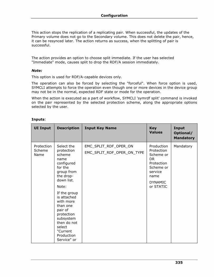
Configuration
335
This action stops the replication of a replicating pair. When successful, the updates of the
Primary volume does not go to the Secondary volume. This does not delete the pair, hence,
it can be resynced later. The action returns as success, when the splitting of pair is
successful.
The action provides an option to choose split immediate. If the user has selected
"Immediate" mode, causes split to drop the RDF/A session immediately.
Note:
This option is used for RDF/A-capable devices only.
The operation can also be forced by selecting the "forceful". When force option is used,
SYMCLI attempts to force the operation even though one or more devices in the device group
may not be in the normal, expected RDF state or mode for the operation.
When the action is executed as a part of workflow, SYMCLI 'symrdf split' command is invoked
on the pair represented by the selected protection scheme, along the appropriate options
selected by the user.
Inputs:
UI Input Description Input Key Name
Key
Values
Input
Optional/
Mandatory
Protection
Scheme
Name
Select the
protection
scheme
name
configured
for the
group from
the drop-
down list.
Note:
If the group
is attached
with more
than one
pair of
protection
subsystem
then do not
select
"Current
Production
Service" or
EMC_SPLIT_RDF_OPER_ON
EMC_SPLIT_RDF_OPER_ON_TYPE
Production
Protection
Scheme or
DR
Protection
Scheme or
service
name
DYNAMIC
or STATIC
Mandatory

IBM Resiliency Orchestration Administrator’s Guide
© IBM Corporation 2017 336
UI Input Description Input Key Name
Key
Values
Input
Optional/
Mandatory
"Current DR
Service".
Instead,
select the
actual
protection
subsystem
to configure
the
operation.
Mode Select the
mode of
operation.
EMC_SPLIT_RDF_MODE Immediate Optional
Forceful Click the
checkbox if
the
operation
has to be
forced.
EMC_SPLIT_RDF_FORCE True or
False.
(It is False
by
default).
Optional
Outputs:
There are no output keys for this action.
Execution Log:
SYMCLI
Command:
symrdf -g <devGrpName> split <-
immediate> <-force> -noprompt
Result: Execution <success/failed>
SYMCLI
Output:
<CLI Output>
Pre-checks
▪ Configuration – Action is configured with input of Key Values or Advance Properties.

Configuration
337
▪ Agent connectivity.
▪ Authentication (Password check for Agentless).
getRDFStatus
This action reports the RDF pair status (EMC specific pair status that indicates the current
state of replication).
When the action is executed as a part of the workflow, 'symdg show' command is invoked on
the device group represented by the selected protection scheme. Success or failure of the
action is determined by the ouput of the command.
Inputs:
UI Input Description Input Key Name
Key
Values
Input
Optional/
Mandatory
Protection
Scheme
Name
Select the
protection
scheme
name
configured
for the
group from
the drop-
down list.
Note:
If the group
is attached
with more
than one
pair of
protection
subsystem
then do not
select
"Current
Production
Service" or
"Current DR
Service".
Instead,
select the
actual
protection
EMC_STATUS_RDF_OPER_ON
EMC_STATUS_RDF_OPER_ON_TYPE
Production
Protection
Scheme or
DR
Protection
Scheme or
service
name
DYNAMIC
or STATIC
Mandatory
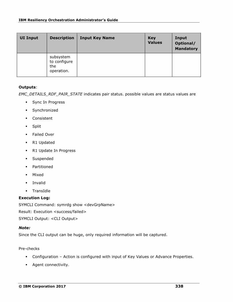
IBM Resiliency Orchestration Administrator’s Guide
© IBM Corporation 2017 338
UI Input Description Input Key Name
Key
Values
Input
Optional/
Mandatory
subsystem
to configure
the
operation.
Outputs:
EMC_DETAILS_RDF_PAIR_STATE indicates pair status. possible values are status values are
▪ Sync In Progress
▪ Synchronized
▪ Consistent
▪ Split
▪ Failed Over
▪ R1 Updated
▪ R1 Update In Progress
▪ Suspended
▪ Partitioned
▪ Mixed
▪ Invalid
▪ TransIdle
Execution Log:
SYMCLI Command: symrdg show <devGrpName>
Result: Execution <success/failed>
SYMCLI Output: <CLI Output>
Note:
Since the CLI output can be huge, only required information will be captured.
Pre-checks
▪ Configuration – Action is configured with input of Key Values or Advance Properties.
▪ Agent connectivity.

Configuration
339
▪ Authentication (Password check for agentless).
verifyRDFStatus
This action is used to verify the status of RDF pair. When this action is executed it checks for
the current status of the pair and if a match occurs with what user has asked for then, this
action is considered as success.
When the action is executed as a part of the workflow, The command 'symdg show' is
invoked on the device group represented by the selected protection scheme. Success or
failure of the action is determined by the ouput of the command.
Inputs:
UI Input Description Input Key Name
Key Values Input
Optional/
Mandatory
Protection
Scheme
Name
Select the
protection
scheme
name
configured
for the
group from
the drop-
down list.
Note:
If the group
is attached
with more
than one
pair of
protection
subsystem
then do not
select
"Current
Production
Service" or
"Current DR
Service".
Instead,
select the
actual
protection
subsystem
to configure
EMC_VERIFY_STATUS_
RDF_OPER_ON
EMC_VERIFY_STATUS_
RDF_OPER_ON_TYPE
Production Protection
Scheme or DR
Protection Scheme or
service name.
DYNAMIC or STATIC
Mandatory
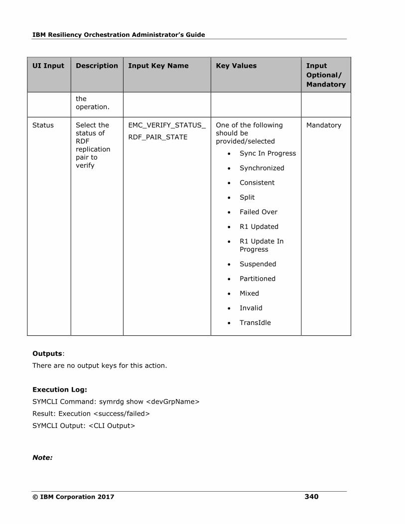
IBM Resiliency Orchestration Administrator’s Guide
© IBM Corporation 2017 340
UI Input Description Input Key Name
Key Values Input
Optional/
Mandatory
the
operation.
Status Select the
status of
RDF
replication
pair to
verify
EMC_VERIFY_STATUS_
RDF_PAIR_STATE
One of the following
should be
provided/selected
• Sync In Progress
• Synchronized
• Consistent
• Split
• Failed Over
• R1 Updated
• R1 Update In
Progress
• Suspended
• Partitioned
• Mixed
• Invalid
• TransIdle
Mandatory
Outputs:
There are no output keys for this action.
Execution Log:
SYMCLI Command: symrdg show <devGrpName>
Result: Execution <success/failed>
SYMCLI Output: <CLI Output>
Note:
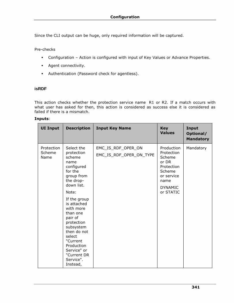
Configuration
341
Since the CLI output can be huge, only required information will be captured.
Pre-checks
▪ Configuration – Action is configured with input of Key Values or Advance Properties.
▪ Agent connectivity.
▪ Authentication (Password check for agentless).
isRDF
This action checks whether the protection service name R1 or R2. If a match occurs with
what user has asked for then, this action is considered as success else it is considered as
failed if there is a mismatch.
Inputs:
UI Input Description Input Key Name Key
Values
Input
Optional/
Mandatory
Protection
Scheme
Name
Select the
protection
scheme
name
configured
for the
group from
the drop-
down list.
Note:
If the group
is attached
with more
than one
pair of
protection
subsystem
then do not
select
"Current
Production
Service" or
"Current DR
Service".
Instead,
EMC_IS_RDF_OPER_ON
EMC_IS_RDF_OPER_ON_TYPE
Production
Protection
Scheme
or DR
Protection
Scheme
or service
name
DYNAMIC
or STATIC
Mandatory

IBM Resiliency Orchestration Administrator’s Guide
© IBM Corporation 2017 342
UI Input Description Input Key Name Key
Values
Input
Optional/
Mandatory
select the
actual
protection
subsystem
to configure
the
operation.
RDF Type Select the
mode of
operation.
EMC_IS_RDF_SRDF_TYPE R1 or R2 Mandatory
Description:
This action can be used to check if the protection scheme is RDF.
Outputs:
There are no output keys for this action.
Execution Log:
<Protection scheme> is <R1/R2>
Pre-checks
▪ Configuration – Action is configured with input of Key Values or Advance Properties.
▪ Agent connectivity.
▪ Authentication (Password check for agentless).
failoverRDF
This action executes the EMC 'symrdf' command which switches data processing from the
source (R1) to the target (R2) side.
When the action is executed as a part of the workflow, the command 'symrdf failover' is
invoked on the device group represented by the selected protection scheme along with the
appropriate options if any chosen by the user. Success or failure of the action is determined
by the ouput of the command.
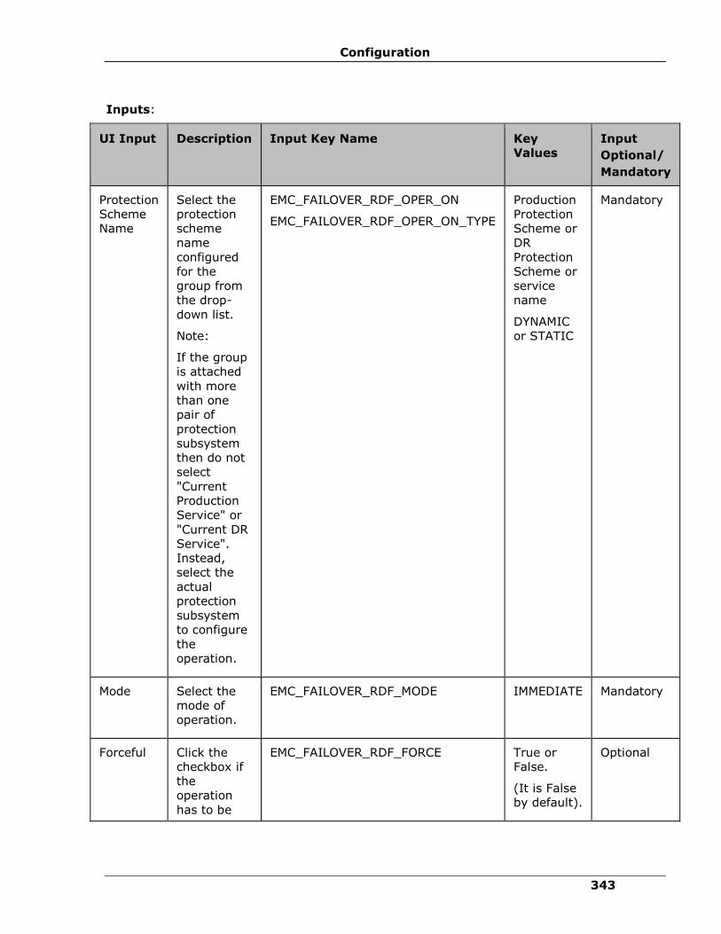
Configuration
343
Inputs:
UI Input Description Input Key Name
Key
Values
Input
Optional/
Mandatory
Protection
Scheme
Name
Select the
protection
scheme
name
configured
for the
group from
the drop-
down list.
Note:
If the group
is attached
with more
than one
pair of
protection
subsystem
then do not
select
"Current
Production
Service" or
"Current DR
Service".
Instead,
select the
actual
protection
subsystem
to configure
the
operation.
EMC_FAILOVER_RDF_OPER_ON
EMC_FAILOVER_RDF_OPER_ON_TYPE
Production
Protection
Scheme or
DR
Protection
Scheme or
service
name
DYNAMIC
or STATIC
Mandatory
Mode Select the
mode of
operation.
EMC_FAILOVER_RDF_MODE IMMEDIATE Mandatory
Forceful Click the
checkbox if
the
operation
has to be
EMC_FAILOVER_RDF_FORCE True or
False.
(It is False
by default).
Optional

IBM Resiliency Orchestration Administrator’s Guide
© IBM Corporation 2017 344
UI Input Description Input Key Name
Key
Values
Input
Optional/
Mandatory
forced.
Outputs:
There are no output keys for this action.
Execution Log:
SYMCLI Command: symrdf -g <devGrpName> failover <-immediate> <-force> -noprompt
Result: Execution <success/failed>
SYMCLI Output: <CLI Output>
Pre-checks
▪ Configuration – Action is configured with input of Key Values or Advance Properties.
▪ Agent connectivity.
▪ Authentication (Password check for agentless).
failBackRDF
This action executes the EMC 'symrdf' command which switches data processing back to the
source (R1) side.
When this action is executed as a part of the workflow,the command 'symrdf failback' is
invoked on the device group represented by the selected protection scheme along with the
appropriate options if any chosen by the user. Success or failure of the action is determined
by the ouput of the command.
Inputs:
UI Input Description Input Key Name Key
Values
Input
Optional/
Mandatory
Protection
Scheme
Name
Select the
protection
scheme
name
configured
EMC_FAILBACK_RDF_OPER_ON Production
Protection
Scheme
or DR
Protection
Mandatory
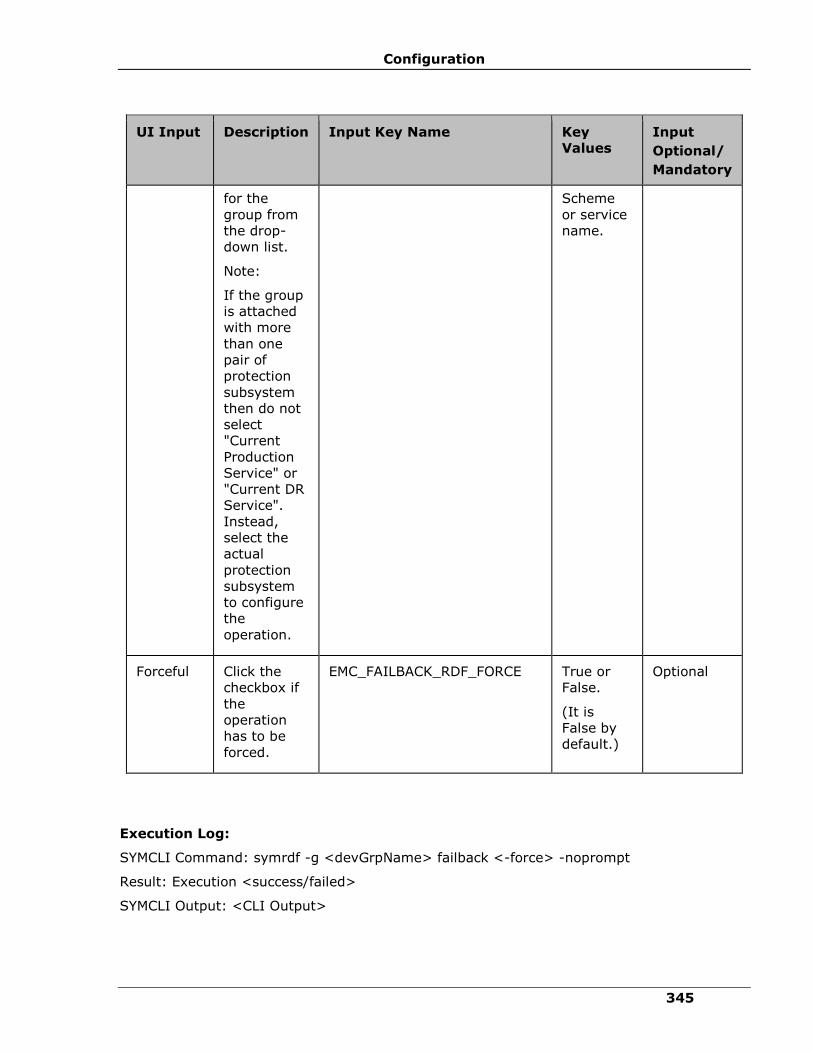
Configuration
345
UI Input Description Input Key Name Key
Values
Input
Optional/
Mandatory
for the
group from
the drop-
down list.
Note:
If the group
is attached
with more
than one
pair of
protection
subsystem
then do not
select
"Current
Production
Service" or
"Current DR
Service".
Instead,
select the
actual
protection
subsystem
to configure
the
operation.
Scheme
or service
name.
Forceful Click the
checkbox if
the
operation
has to be
forced.
EMC_FAILBACK_RDF_FORCE True or
False.
(It is
False by
default.)
Optional
Execution Log:
SYMCLI Command: symrdf -g <devGrpName> failback <-force> -noprompt
Result: Execution <success/failed>
SYMCLI Output: <CLI Output>
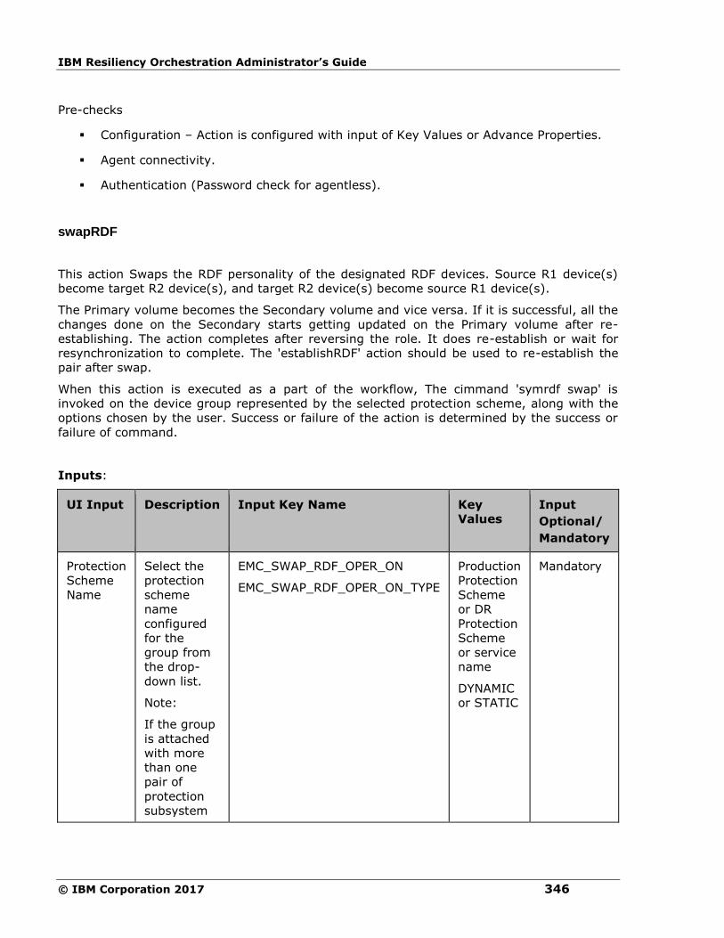
IBM Resiliency Orchestration Administrator’s Guide
© IBM Corporation 2017 346
Pre-checks
▪ Configuration – Action is configured with input of Key Values or Advance Properties.
▪ Agent connectivity.
▪ Authentication (Password check for agentless).
swapRDF
This action Swaps the RDF personality of the designated RDF devices. Source R1 device(s)
become target R2 device(s), and target R2 device(s) become source R1 device(s).
The Primary volume becomes the Secondary volume and vice versa. If it is successful, all the
changes done on the Secondary starts getting updated on the Primary volume after re-
establishing. The action completes after reversing the role. It does re-establish or wait for
resynchronization to complete. The 'establishRDF' action should be used to re-establish the
pair after swap.
When this action is executed as a part of the workflow, The cimmand 'symrdf swap' is
invoked on the device group represented by the selected protection scheme, along with the
options chosen by the user. Success or failure of the action is determined by the success or
failure of command.
Inputs:
UI Input Description Input Key Name
Key
Values
Input
Optional/
Mandatory
Protection
Scheme
Name
Select the
protection
scheme
name
configured
for the
group from
the drop-
down list.
Note:
If the group
is attached
with more
than one
pair of
protection
subsystem
EMC_SWAP_RDF_OPER_ON
EMC_SWAP_RDF_OPER_ON_TYPE
Production
Protection
Scheme
or DR
Protection
Scheme
or service
name
DYNAMIC
or STATIC
Mandatory

Configuration
347
UI Input Description Input Key Name
Key
Values
Input
Optional/
Mandatory
then do not
select
"Current
Production
Service" or
"Current DR
Service".
Instead,
select the
actual
protection
subsystem
to configure
the
operation.
Forceful Click the
checkbox if
the
operation
has to be
forced.
EMC_SWAP_RDF_FORCE True or
False.
(It is
False by
default).
Optional
Outputs:
There are no output keys for this action.
Execution Log:
SYMCLI Command: symrdf -g <devGrpName> swap <-force> -noprompt
Result: Execution <success/failed>
SYMCLI Output: <CLI Output>
Pre-checks
▪ Configuration – Action is configured with input of Key Values or Advance Properties.
▪ Agent connectivity.
▪ Authentication (Password check for agentless).
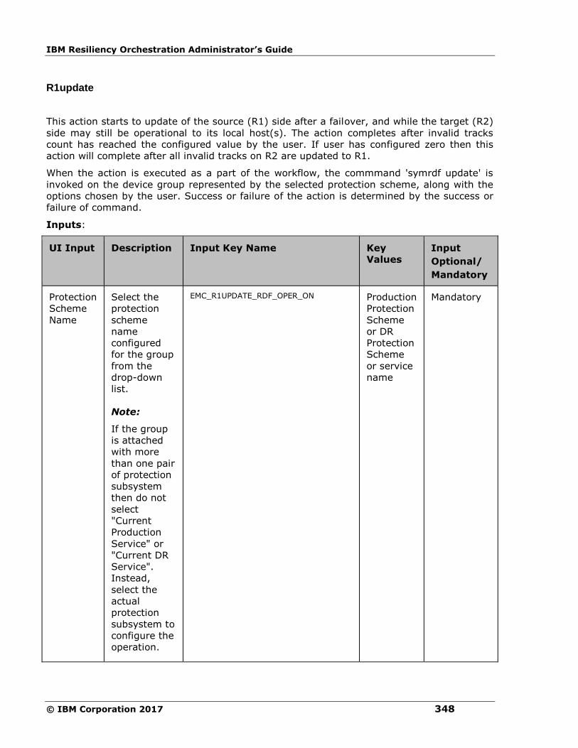
IBM Resiliency Orchestration Administrator’s Guide
© IBM Corporation 2017 348
R1update
This action starts to update of the source (R1) side after a failover, and while the target (R2)
side may still be operational to its local host(s). The action completes after invalid tracks
count has reached the configured value by the user. If user has configured zero then this
action will complete after all invalid tracks on R2 are updated to R1.
When the action is executed as a part of the workflow, the commmand 'symrdf update' is
invoked on the device group represented by the selected protection scheme, along with the
options chosen by the user. Success or failure of the action is determined by the success or
failure of command.
Inputs:
UI Input Description Input Key Name
Key
Values
Input
Optional/
Mandatory
Protection
Scheme
Name
Select the
protection
scheme
name
configured
for the group
from the
drop-down
list.
Note:
If the group
is attached
with more
than one pair
of protection
subsystem
then do not
select
"Current
Production
Service" or
"Current DR
Service".
Instead,
select the
actual
protection
subsystem to
configure the
operation.
EMC_R1UPDATE_RDF_OPER_ON Production
Protection
Scheme
or DR
Protection
Scheme
or service
name
Mandatory
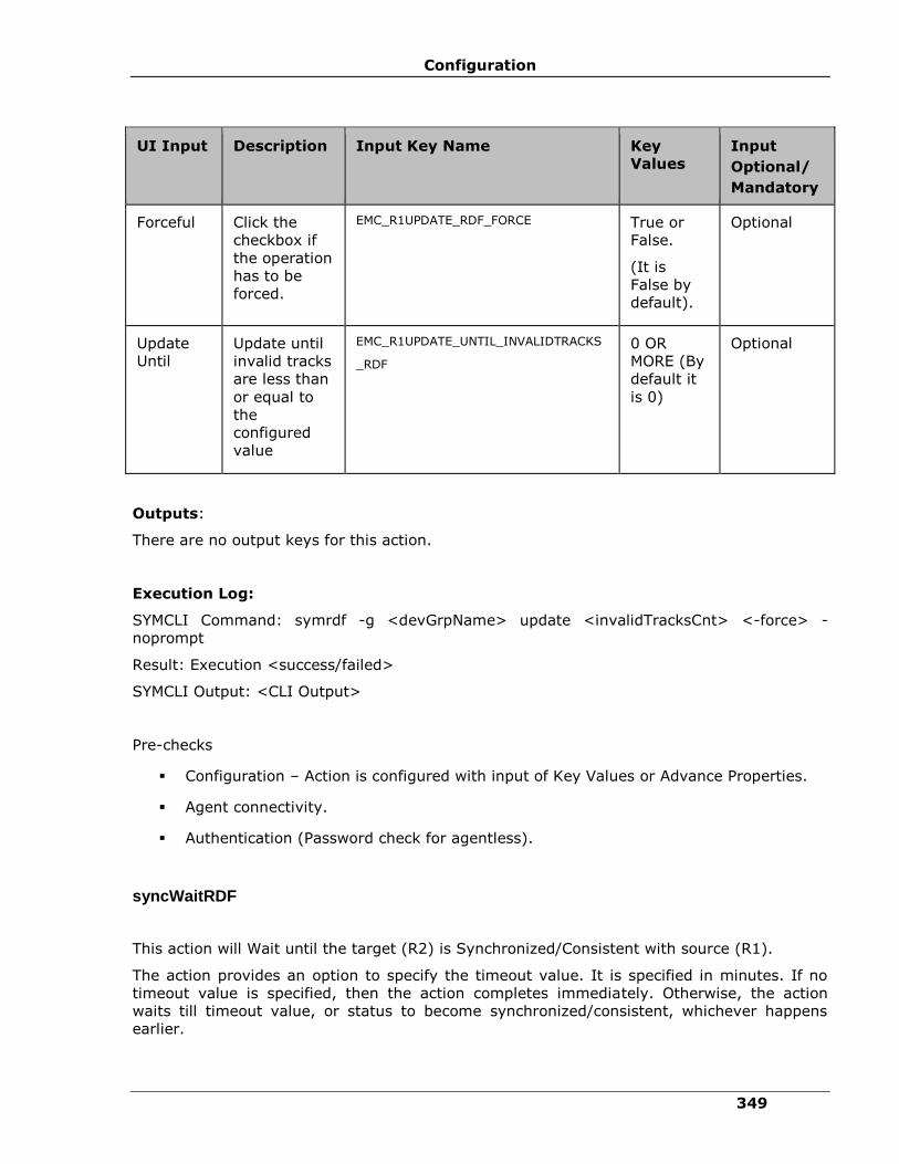
Configuration
349
UI Input Description Input Key Name
Key
Values
Input
Optional/
Mandatory
Forceful Click the
checkbox if
the operation
has to be
forced.
EMC_R1UPDATE_RDF_FORCE True or
False.
(It is
False by
default).
Optional
Update
Until
Update until
invalid tracks
are less than
or equal to
the
configured
value
EMC_R1UPDATE_UNTIL_INVALIDTRACKS
_RDF
0 OR
MORE (By
default it
is 0)
Optional
Outputs:
There are no output keys for this action.
Execution Log:
SYMCLI Command: symrdf -g <devGrpName> update <invalidTracksCnt> <-force> -
noprompt
Result: Execution <success/failed>
SYMCLI Output: <CLI Output>
Pre-checks
▪ Configuration – Action is configured with input of Key Values or Advance Properties.
▪ Agent connectivity.
▪ Authentication (Password check for agentless).
syncWaitRDF
This action will Wait until the target (R2) is Synchronized/Consistent with source (R1).
The action provides an option to specify the timeout value. It is specified in minutes. If no
timeout value is specified, then the action completes immediately. Otherwise, the action
waits till timeout value, or status to become synchronized/consistent, whichever happens
earlier.

IBM Resiliency Orchestration Administrator’s Guide
© IBM Corporation 2017 350
When the action is executed as a part of the workflow, the command 'symrdf verify' is
invoked on the device group represented by the selected protection scheme, along with the
options chosen by the user. The action is considered success if status becomes
Synchronized/Consistent, failed otherwise.
Inputs:
UI Input Description Input Key Name Key
Values
Input
Optional/
Mandatory
Protection
Scheme
Name
Select the
protection
scheme
name
configured
for the
group from
the drop-
down list.
Note:
If the group
is attached
with more
than one
pair of
protection
subsystem
then do not
select
"Current
Production
Service" or
"Current DR
Service".
Instead,
select the
actual
protection
subsystem
to configure
the
operation.
EMC_SYNCWAIT_RDF_OPER_ON
EMC_SYNCWAIT_RDF_OPER_ON_TYPE
Production
Protection
Scheme
or DR
Protection
Scheme
or service
name
DYNAMIC
or STATIC
Mandatory
Operation
timeout
(in
minutes)
zero will
verify once,
any other
positive
integer will
EMC_SYNCWAIT_RDF_TIMEOUT 0 or more
(It is 0 by
default).
Optional

Configuration
351
UI Input Description Input Key Name Key
Values
Input
Optional/
Mandatory
verify every
30 seconds.
Outputs:
There are no output keys for this action.
Pre-checks
▪ Configuration – Action is configured with input of Key Values or Advance Properties.
▪ Agent connectivity.
▪ Authentication (Password check for agentless).
Hitachi TrueCopy
Resync TrueCopy
Description:
This action re-establishes a split pair and then restarts the update copy operations to the
Secondary volume. If successful, all the changes done on the Primary starts getting updated
on the Secondary volume. The action completes after initiating the resync request and does
not wait for the resynchronization to complete. 'Check Status' or 'Verify Status' action should
be used to check if the pair has arrived to a particular state.
When the action is run as a part of workflow, CCI 'pairresync' command is invoked on the
pair represented by the selected protection scheme, along with the options chosen by the
user. If all the pairs of groups are successfully resynced, the action returns as success. In all
other cases, it returns as failure. Success or failure of the action depends on success or
failure of the 'pairresync' command. Refer to Outputs and Errors table below for details.
CCI command: pairresync -g <name>.
Input:
UI Input Input Key Name Description
Protection
Scheme
RESYNC_TC_OPER_ON,
RESYNC_TC_OPER_ON_TYPE
Select the protection scheme
name configured for the group
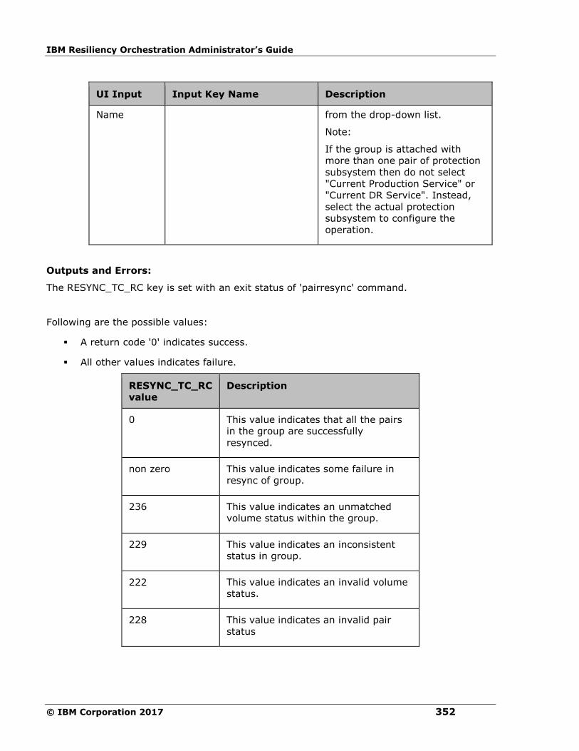
IBM Resiliency Orchestration Administrator’s Guide
© IBM Corporation 2017 352
UI Input Input Key Name Description
Name from the drop-down list.
Note:
If the group is attached with
more than one pair of protection
subsystem then do not select
"Current Production Service" or
"Current DR Service". Instead,
select the actual protection
subsystem to configure the
operation.
Outputs and Errors:
The RESYNC_TC_RC key is set with an exit status of 'pairresync' command.
Following are the possible values:
▪ A return code '0' indicates success.
▪ All other values indicates failure.
RESYNC_TC_RC
value
Description
0 This value indicates that all the pairs
in the group are successfully
resynced.
non zero This value indicates some failure in
resync of group.
236 This value indicates an unmatched
volume status within the group.
229 This value indicates an inconsistent
status in group.
222 This value indicates an invalid volume
status.
228 This value indicates an invalid pair
status

Configuration
353
Pre-checks
▪ Configuration – Action is configured with input of Key Values or Advance Properties.
▪ Agent connectivity.
▪ Authentication (Password check for agentless).
▪ HORCM services are running or not.
(This pre-check also supports that the agent is running and the access credentials are
correct).
Split TrueCopy
Description:
This action stops the replication of a replicating pair. When successful, the updates of the
Primary volume does not go to the Secondary volume. This does not delete the pair, hence,
it can be resynced later. The action returns as success, when the splitting of pair is
successful.
The action provides an option to choose SVOL access: READ or READWRITE. If the user has
selected READWRITE, then the Secondary volume will be in READWRITE mode after the
successful split.
When the action is run as a part of workflow, CCI 'pairsplit' command is invoked on the pair
represented by the selected protection scheme, along with the options chosen by the user.
Success or failure of the action is determined by the success or failure of 'pairsplit' command.
Refer to Outputs and Errors table below for details.
CCI command:
▪ If the user has selected default value for SVOL Access: pairsplit -g <name>.
▪ If read: pairsplit -g <name> -r.
▪ If user has selected readwrite: pairsplit -g <name> -rw.
Inputs:
UI Input Input Key Name Description
Protection
Scheme
Name
SPLIT_TC_OPER_ON,
SPLIT_TC_OPER_ON_TYPE
Select the protection scheme
name configured for the group
from the drop-down list.
Note:
If the group is attached with
more than one pair of
protection subsystem then do
not select "Current Production

IBM Resiliency Orchestration Administrator’s Guide
© IBM Corporation 2017 354
UI Input Input Key Name Description
Service" or "Current DR
Service". Instead, select the
actual protection subsystem to
configure the operation.
SVOL
Access
SPLIT_TC_SVOL_ACCESS
Select an appropriate option
from the drop-down list. The
options are:
▪ READ
▪ READWRITE
Outputs and Errors:
The SPLIT_TC_RC key is set with an exit status of 'pairsplit' command.
Following are the possible values:
▪ A return code '0' indicates success.
▪ All other values indicates failure.
SPLIT_TC_RC value Description
0 This value indicates that all the pairs in
the group are successfully suspended.
non zero This value indicates some failure in
splitting of group.
236 This value indicates an unmatched
volume status within the group.
229 This value indicates an inconsistent status
in group.
222 This value indicates an invalid volume
status.
235 This value indicates a Pair Volume
combination error.
228 This value indicates an invalid pair status
234 This value indicates a Pair suspended at
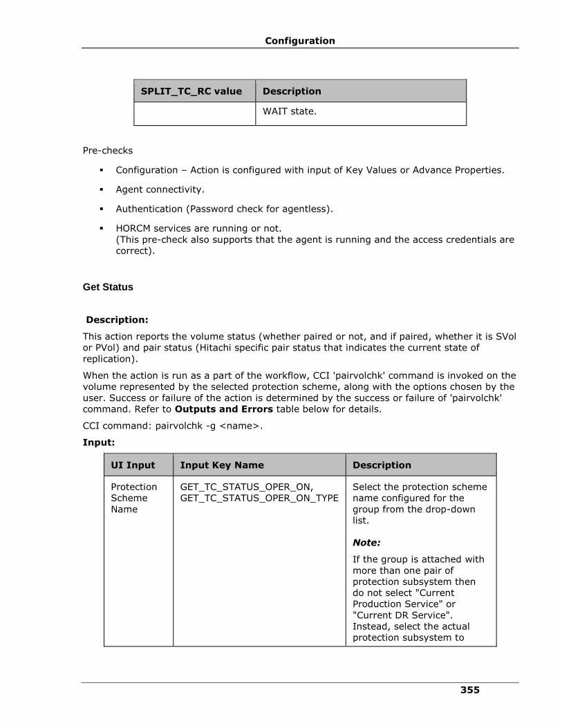
Configuration
355
SPLIT_TC_RC value Description
WAIT state.
Pre-checks
▪ Configuration – Action is configured with input of Key Values or Advance Properties.
▪ Agent connectivity.
▪ Authentication (Password check for agentless).
▪ HORCM services are running or not.
(This pre-check also supports that the agent is running and the access credentials are
correct).
Get Status
Description:
This action reports the volume status (whether paired or not, and if paired, whether it is SVol
or PVol) and pair status (Hitachi specific pair status that indicates the current state of
replication).
When the action is run as a part of the workflow, CCI 'pairvolchk' command is invoked on the
volume represented by the selected protection scheme, along with the options chosen by the
user. Success or failure of the action is determined by the success or failure of 'pairvolchk'
command. Refer to Outputs and Errors table below for details.
CCI command: pairvolchk -g <name>.
Input:
UI Input Input Key Name Description
Protection
Scheme
Name
GET_TC_STATUS_OPER_ON,
GET_TC_STATUS_OPER_ON_TYPE
Select the protection scheme
name configured for the
group from the drop-down
list.
Note:
If the group is attached with
more than one pair of
protection subsystem then
do not select "Current
Production Service" or
"Current DR Service".
Instead, select the actual
protection subsystem to

IBM Resiliency Orchestration Administrator’s Guide
© IBM Corporation 2017 356
configure the operation.
Outputs and Errors:
The GET_TC_STATUS_RC key is set with an exit status of 'pairvolchk' command.
Following are possible values:
▪ GET_TC_STATUS_VOL_STATUS indicates volume status.The possible values are
PVOL/SVOL/SMPL.
▪ GET_TC_STATUS_PAIR_STATUS indicates the pair status. The possible values are
status value for pair, such as, like PAIR/COPY/PSUS etc.
▪ The return code 0-127 indicates success of action. All other values indicate failure.
GET_TC_STATUS_RC
value
Description
0-127 These values indicates specific exit codes that
represents the state of volume and pair. (e.g. 22:
PVOL_COPY).
Refer to Hitachi CCI documentation for details.
236 This value indicates an unmatched volume status
within the group.
235 This value indicates a Pair Volume combination
error.
Pre-checks
▪ Configuration – Action is configured with input of Key Values or Advance Properties.
▪ Agent connectivity.
▪ Authentication (Password check for agentless).
▪ HORCM services are running or not. (This pre-check also supports that the agent is
running and the access credentials are correct).
Verify Status
Description:
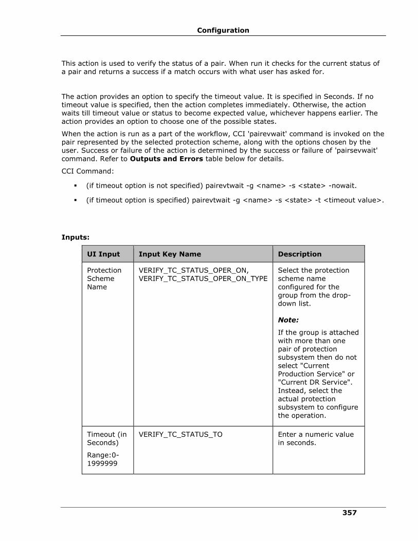
Configuration
357
This action is used to verify the status of a pair. When run it checks for the current status of
a pair and returns a success if a match occurs with what user has asked for.
The action provides an option to specify the timeout value. It is specified in Seconds. If no
timeout value is specified, then the action completes immediately. Otherwise, the action
waits till timeout value or status to become expected value, whichever happens earlier. The
action provides an option to choose one of the possible states.
When the action is run as a part of the workflow, CCI 'pairevwait' command is invoked on the
pair represented by the selected protection scheme, along with the options chosen by the
user. Success or failure of the action is determined by the success or failure of 'pairsevwait'
command. Refer to Outputs and Errors table below for details.
CCI Command:
▪ (if timeout option is not specified) pairevtwait -g <name> -s <state> -nowait.
▪ (if timeout option is specified) pairevtwait -g <name> -s <state> -t <timeout value>.
Inputs:
UI Input Input Key Name Description
Protection
Scheme
Name
VERIFY_TC_STATUS_OPER_ON,
VERIFY_TC_STATUS_OPER_ON_TYPE
Select the protection
scheme name
configured for the
group from the drop-
down list.
Note:
If the group is attached
with more than one
pair of protection
subsystem then do not
select "Current
Production Service" or
"Current DR Service".
Instead, select the
actual protection
subsystem to configure
the operation.
Timeout (in
Seconds)
Range:0-
1999999
VERIFY_TC_STATUS_TO Enter a numeric value
in seconds.
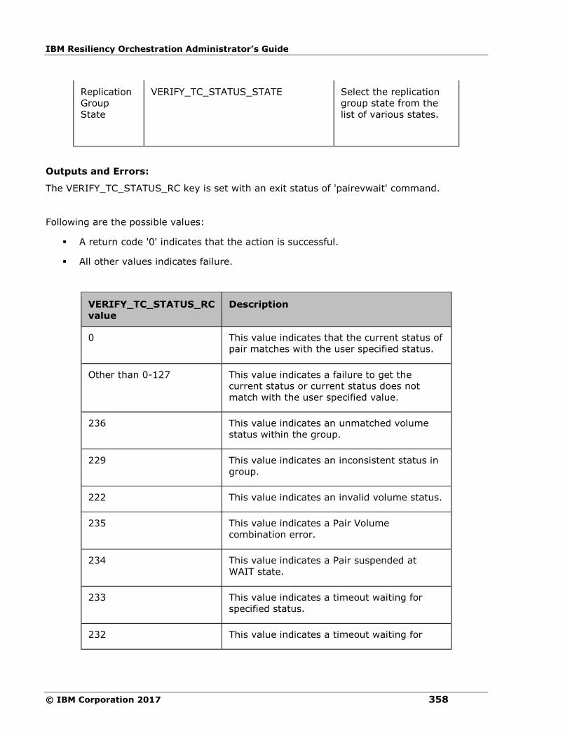
IBM Resiliency Orchestration Administrator’s Guide
© IBM Corporation 2017 358
Replication
Group
State
VERIFY_TC_STATUS_STATE Select the replication
group state from the
list of various states.
Outputs and Errors:
The VERIFY_TC_STATUS_RC key is set with an exit status of 'pairevwait' command.
Following are the possible values:
▪ A return code '0' indicates that the action is successful.
▪ All other values indicates failure.
VERIFY_TC_STATUS_RC
value
Description
0 This value indicates that the current status of
pair matches with the user specified status.
Other than 0-127 This value indicates a failure to get the
current status or current status does not
match with the user specified value.
236 This value indicates an unmatched volume
status within the group.
229 This value indicates an inconsistent status in
group.
222 This value indicates an invalid volume status.
235 This value indicates a Pair Volume
combination error.
234 This value indicates a Pair suspended at
WAIT state.
233 This value indicates a timeout waiting for
specified status.
232 This value indicates a timeout waiting for
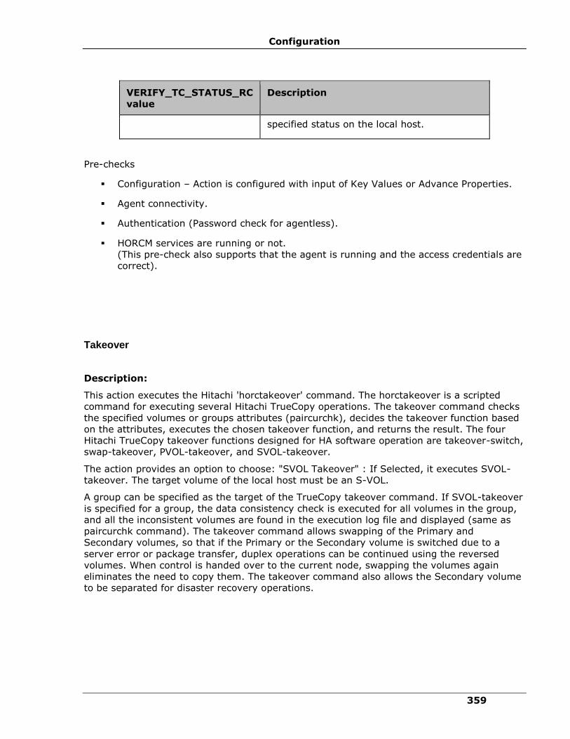
Configuration
359
VERIFY_TC_STATUS_RC
value
Description
specified status on the local host.
Pre-checks
▪ Configuration – Action is configured with input of Key Values or Advance Properties.
▪ Agent connectivity.
▪ Authentication (Password check for agentless).
▪ HORCM services are running or not.
(This pre-check also supports that the agent is running and the access credentials are
correct).
Takeover
Description:
This action executes the Hitachi 'horctakeover' command. The horctakeover is a scripted
command for executing several Hitachi TrueCopy operations. The takeover command checks
the specified volumes or groups attributes (paircurchk), decides the takeover function based
on the attributes, executes the chosen takeover function, and returns the result. The four
Hitachi TrueCopy takeover functions designed for HA software operation are takeover-switch,
swap-takeover, PVOL-takeover, and SVOL-takeover.
The action provides an option to choose: "SVOL Takeover" : If Selected, it executes SVOL-
takeover. The target volume of the local host must be an S-VOL.
A group can be specified as the target of the TrueCopy takeover command. If SVOL-takeover
is specified for a group, the data consistency check is executed for all volumes in the group,
and all the inconsistent volumes are found in the execution log file and displayed (same as
paircurchk command). The takeover command allows swapping of the Primary and
Secondary volumes, so that if the Primary or the Secondary volume is switched due to a
server error or package transfer, duplex operations can be continued using the reversed
volumes. When control is handed over to the current node, swapping the volumes again
eliminates the need to copy them. The takeover command also allows the Secondary volume
to be separated for disaster recovery operations.

IBM Resiliency Orchestration Administrator’s Guide
© IBM Corporation 2017 360
The takeover command, when activated by a control script, checks for the combination of
attributes of the local and remote volumes and determines the proper takeover action.
Various takeover functions that can be executed are Nop-takeover, Swap-takeover, SVOL-
takeover, PVOL-SMPL-takeover, PVOL-PSUE-takeover and SVOL-SSUS-takeover. If the
command fails, the error message and the error code is returned. If the command succeeds,
the return code and the message tells which takeover sub function is executed. To get the
details about the horctakeover sub functions and what state cause which function to initiate,
please refer to applicable Command Control Reference guide.
Note:
Hitachi horctakeover command many times returns currency error even if the volumes are
consistent. In such cases, takeover action returns failure. User is expected to verify the
volumes before proceeding to next action. For more details, please refer to CCI guide
(paircuchk).
CCI command:
▪ If SVOL takeover option is not selected: horctakeover -g <name>.
▪ If SVOL takeover option is selected: horctakeover -g <name> -S.
Inputs:
UI Input Input Key Name Description
Protection
Scheme
Name
TAKEOVER_TC_OPER_ON,
TAKEOVER_TC_OPER_ON_TYPE
Select the protection
scheme name configured
for the group from the
drop-down list.
Note:
If the group is attached
with more than one pair
of protection subsystem
then do not select
"Current Production
Service" or "Current DR
Service". Instead, select
the actual protection
subsystem to configure
the operation.

Configuration
361
UI Input Input Key Name Description
Volume
Option
TAKEOVER_TC_VOL_OPTIONS
Select SVOL takover
from the drop-down list.
Timeout (in
Seconds)
TAKEOVER_TC_TO Enter a value in the
numeric field. This is
applicable for sync
replication type.
Outputs and Errors:
The TAKEOVER_TC_RC key is set with an exit status of 'horctakeover' command.
Following are the possible values:
▪ Values 0-5 indicates success of action.
▪ All other values indicates failure of action.
TAKEOVER_TC_RC
value
Description
0 This value indicates a Nop-takeover (no
operation).
1 This value indicates that a Swap-
takeover was successfully executed.
2 This value indicates that a SVOL-
takeover was successfully executed.
3 This value indicates that a PVOL-SMPL-
takeover was successfully executed.
4 This value indicates the following:
▪ PVOL-PSUE-takeover was
successfully executed.
▪ SVOL-SSUS-takeover was
successfully executed. (This value
depends on the microcode level.)
5 This value indicates that a SVOL-SSUS-
takeover was successfully executed.
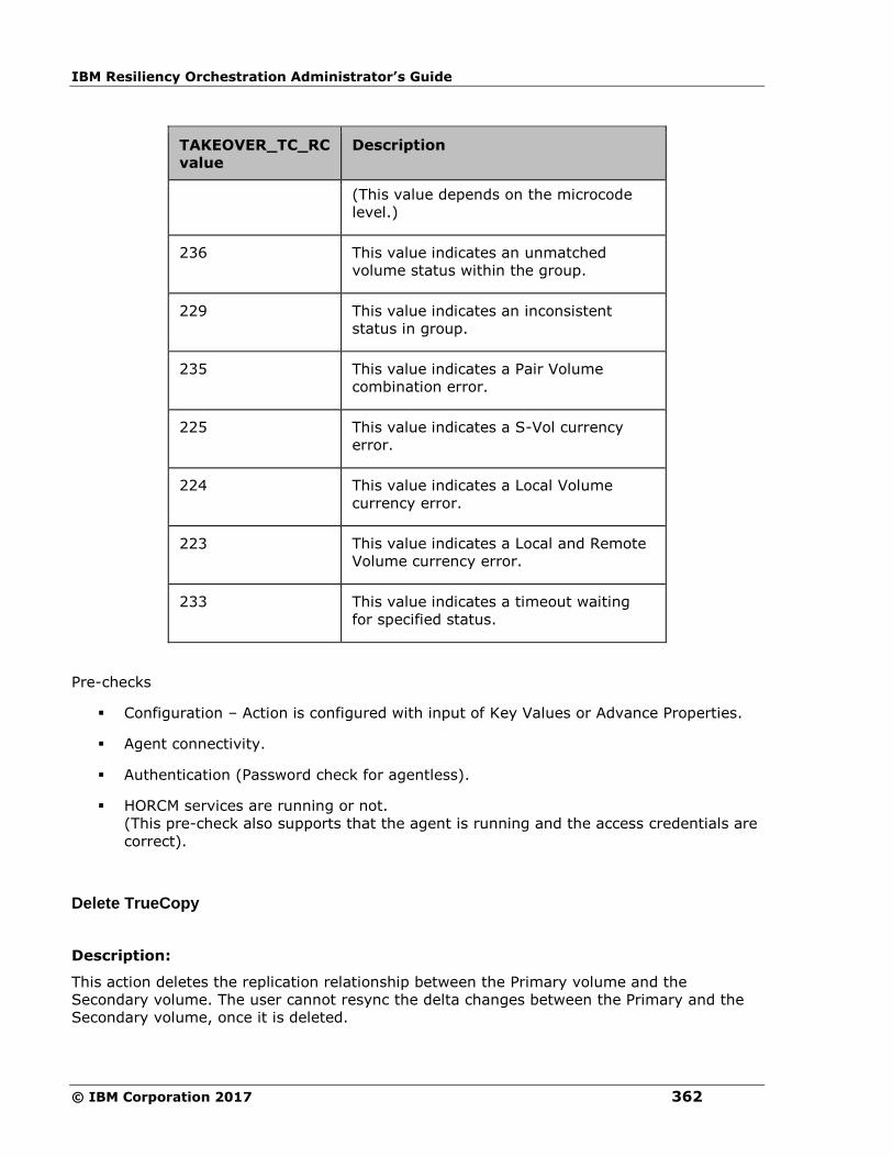
IBM Resiliency Orchestration Administrator’s Guide
© IBM Corporation 2017 362
TAKEOVER_TC_RC
value
Description
(This value depends on the microcode
level.)
236 This value indicates an unmatched
volume status within the group.
229 This value indicates an inconsistent
status in group.
235 This value indicates a Pair Volume
combination error.
225 This value indicates a S-Vol currency
error.
224 This value indicates a Local Volume
currency error.
223 This value indicates a Local and Remote
Volume currency error.
233 This value indicates a timeout waiting
for specified status.
Pre-checks
▪ Configuration – Action is configured with input of Key Values or Advance Properties.
▪ Agent connectivity.
▪ Authentication (Password check for agentless).
▪ HORCM services are running or not.
(This pre-check also supports that the agent is running and the access credentials are
correct).
Delete TrueCopy
Description:
This action deletes the replication relationship between the Primary volume and the
Secondary volume. The user cannot resync the delta changes between the Primary and the
Secondary volume, once it is deleted.
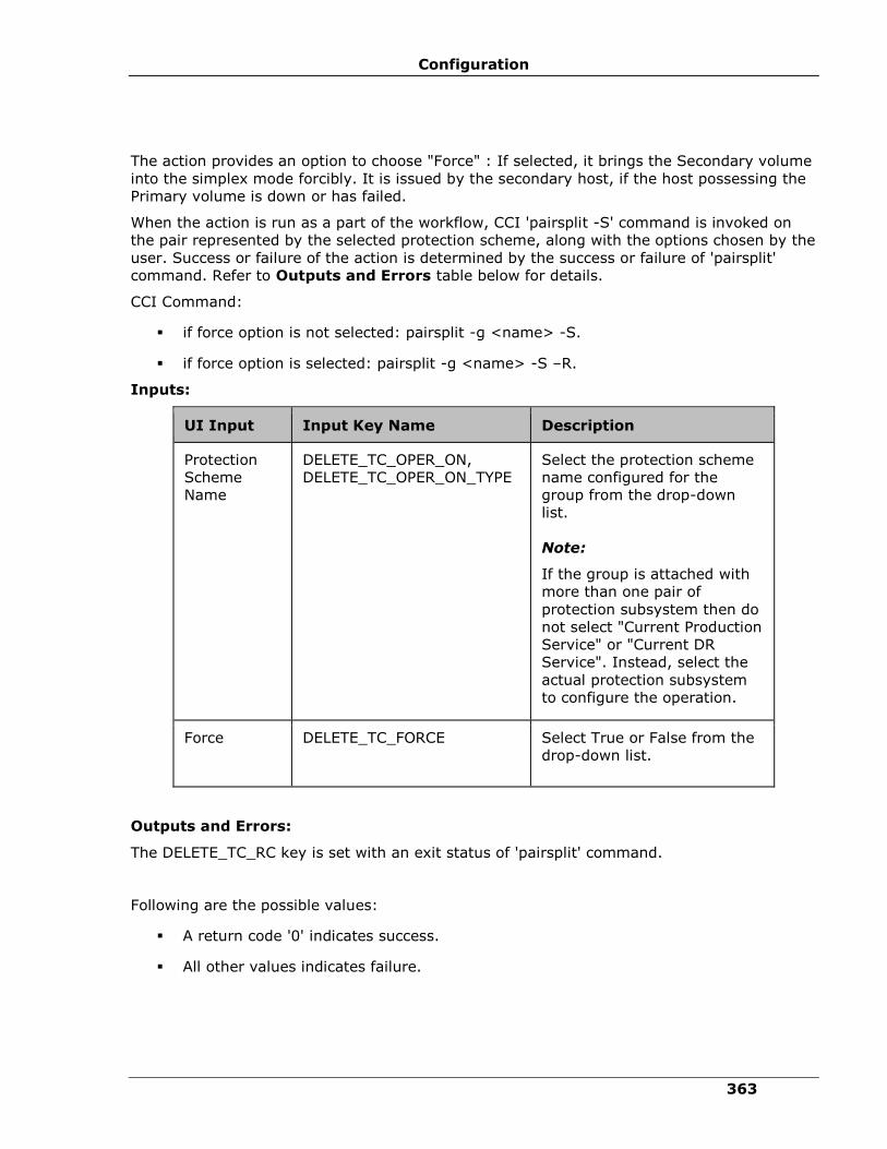
Configuration
363
The action provides an option to choose "Force" : If selected, it brings the Secondary volume
into the simplex mode forcibly. It is issued by the secondary host, if the host possessing the
Primary volume is down or has failed.
When the action is run as a part of the workflow, CCI 'pairsplit -S' command is invoked on
the pair represented by the selected protection scheme, along with the options chosen by the
user. Success or failure of the action is determined by the success or failure of 'pairsplit'
command. Refer to Outputs and Errors table below for details.
CCI Command:
▪ if force option is not selected: pairsplit -g <name> -S.
▪ if force option is selected: pairsplit -g <name> -S –R.
Inputs:
UI Input Input Key Name Description
Protection
Scheme
Name
DELETE_TC_OPER_ON,
DELETE_TC_OPER_ON_TYPE
Select the protection scheme
name configured for the
group from the drop-down
list.
Note:
If the group is attached with
more than one pair of
protection subsystem then do
not select "Current Production
Service" or "Current DR
Service". Instead, select the
actual protection subsystem
to configure the operation.
Force DELETE_TC_FORCE
Select True or False from the
drop-down list.
Outputs and Errors:
The DELETE_TC_RC key is set with an exit status of 'pairsplit' command.
Following are the possible values:
▪ A return code '0' indicates success.
▪ All other values indicates failure.
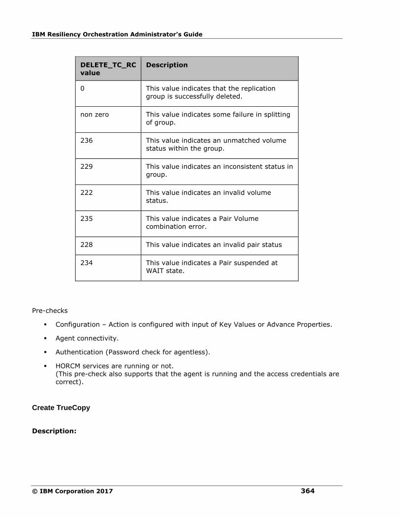
IBM Resiliency Orchestration Administrator’s Guide
© IBM Corporation 2017 364
DELETE_TC_RC
value
Description
0 This value indicates that the replication
group is successfully deleted.
non zero This value indicates some failure in splitting
of group.
236 This value indicates an unmatched volume
status within the group.
229 This value indicates an inconsistent status in
group.
222 This value indicates an invalid volume
status.
235 This value indicates a Pair Volume
combination error.
228 This value indicates an invalid pair status
234 This value indicates a Pair suspended at
WAIT state.
Pre-checks
▪ Configuration – Action is configured with input of Key Values or Advance Properties.
▪ Agent connectivity.
▪ Authentication (Password check for agentless).
▪ HORCM services are running or not.
(This pre-check also supports that the agent is running and the access credentials are
correct).
Create TrueCopy
Description:

Configuration
365
This action creates the replication relationship between the Primary volume and the
Secondary volume. The action returns after the initial copy is initiated between the Primary
and the Secondary Volumes. The user should verify the Replica status to check the desired
status. The replication properties, such as, type of replication (sync/async) or fence level
(Data/status etc) would be the same as per the setting present while discovering protection
scheme or default values.
The action provides an option to choose the direction of replication: forward (Selected
protection scheme as Primary) or reverse (selected protection scheme as Secondary).
The action provides an option to choose fence level: possible values can be status, data and
never. Please refer to Hitachi TrueCopy user guide for details on fence level.
When the action is run as a part of workflow, CCI 'paircreate' command is invoked on the
pair represented by the selected protection scheme, along with the options present while
discovery of object. Success or failure of the action is determined by the success or failure of
'paircreate' command. Refer to Outputs and Errors table below for details.
CCI Command: paircreate -g <name> -f <fence> -vl (if user has selected FORWARD option)
or -vr (if user has selected REVERSE option).
Inputs:
UI Input Input Key Name Description
Protection
Scheme
Name
CREATE_TC_OPER_ON,
CREATE_TC_OPER_ON_TYPE
Select the protection scheme
name configured for the
group from the drop-down
list.
Note:
If the group is attached with
more than one pair of
protection subsystem then do
not select "Current
Production Service" or
"Current DR Service".
Instead, select the actual
protection subsystem to
configure the operation.
Replication
Direction
CREATE_TC_REPL_DIRECTION Select Forward or Reverse
from the drop-down list.
Fence Level CREATE_TC_FENCE Select the appropriate fence
level from the following:
▪ Data
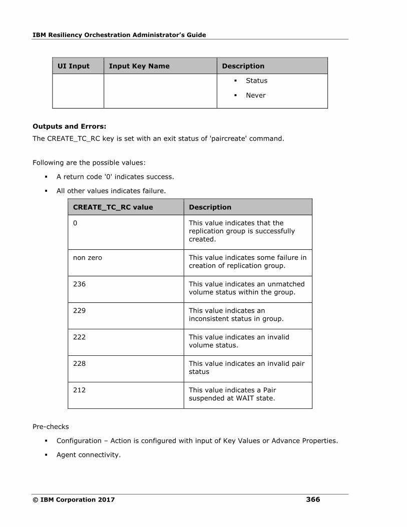
IBM Resiliency Orchestration Administrator’s Guide
© IBM Corporation 2017 366
UI Input Input Key Name Description
▪ Status
▪ Never
Outputs and Errors:
The CREATE_TC_RC key is set with an exit status of 'paircreate' command.
Following are the possible values:
▪ A return code '0' indicates success.
▪ All other values indicates failure.
CREATE_TC_RC value Description
0 This value indicates that the
replication group is successfully
created.
non zero This value indicates some failure in
creation of replication group.
236 This value indicates an unmatched
volume status within the group.
229 This value indicates an
inconsistent status in group.
222 This value indicates an invalid
volume status.
228 This value indicates an invalid pair
status
212 This value indicates a Pair
suspended at WAIT state.
Pre-checks
▪ Configuration – Action is configured with input of Key Values or Advance Properties.
▪ Agent connectivity.

Configuration
367
▪ Authentication (Password check for agentless).
▪ HORCM services are running or not.
(This pre-check also supports that the agent is running and the access credentials are
correct).
Role Switch
Description:
This action re-establishes a split pair in the reverse direction. The Primary volume becomes
the Secondary volume and vice versa. If it is successful, all the changes done on the
Secondary starts getting updated on the Primary volume. The action completes after
reversing the role and initiating the reverse resync request. It does not wait for
resynchronization to complete. The 'Check Status' or 'Verify Status' action should be used to
check if the pair has arrived to a particular state.
When the action is run as a part of the workflow, CCI 'pairresync -swapp or -swaps'
command is invoked on the pair represented by the selected protection scheme, along with
the options chosen by the user. Success or failure of the action is determined by the success
or failure of 'pairresync' command. Refer to Outputs and Errors table below for details.
CCI Command: pairvolchk -g <name> and pairresync -g <name> -swapp.
Input:
UI Input Input Key Name Description
Protection
Scheme
Name
ROLE_SWITCH_TC_OPER_ON,
ROLE_SWITCH_TC_OPER_ON_TYPE
Select the protection
scheme name
configured for the
group from the drop-
down list.
Note:
If the group is
attached with more
than one pair of
protection subsystem
then do not select
"Current Production
Service" or "Current
DR Service". Instead,
select the actual
protection subsystem
to configure the
operation.
Outputs and Errors:

IBM Resiliency Orchestration Administrator’s Guide
© IBM Corporation 2017 368
The ROLE_SWITCH_TC_RC key is set with an exit status of 'pairresync' command.
Following are the possible values:
▪ A return code '0' indicates success.
▪ All other values indicates failure.
ROLE_SWITCH_TC_RC
value
Description
0 This value indicates that the role for all the
pair in the group are successfully reversed.
non zero This value indicates some failure in resync of
group.
236 This value indicates an unmatched volume
status within the group.
229 This value indicates an inconsistent status in
group.
222 This value indicates an invalid volume status.
228 This value indicates an invalid pair status
Pre-checks
▪ Configuration – Action is configured with input of Key Values or Advance Properties.
▪ Agent connectivity.
▪ Authentication (Password check for agentless).
▪ HORCM services are running or not.
(This pre-check also supports that the agent is running and the access credentials are
correct).
Check Consistency
Description:

Configuration
369
This action checks for the consistency of the Secondary volume.The action call Hitachi CCI
'paircurchk' command, which checks for the currency of the Hitachi TrueCopy Secondary
volume(s), by evaluating the data consistency based on pair status and fence level. The
action fails if the Secondary volume is not consistent. Please refer to Hitachi CCI reference
manual to know about the data consistency for each possible states of a Hitachi TrueCopy
volume.
When the action is run as a part of the workflow, CCI 'paircurchk' command is invoked on the
pair represented by the selected protection scheme, along with the options chosen by the
user. The action returns success if the data volumes are consistent. In all other cases, it fails.
Refer to Outputs and Errors table below to for details.
Note
Hitachi paircurchk command many times returns currency error even if the volumes are
consistent. In such cases, consistency check action returns failure. For more details, please
refer to CCI guide (paircuchk).
CCI Command: paircurchk -g <name>.
Inputs:
UI Input Input Key Name Description
Protection
Scheme Name
CHECK_CONSISTENCY_TC_OPER_ON,
CHECK_CONSISTENCY_TC_OPER_ON_TYPE
Select the
protection
scheme name
configured for
the group from
the drop-down
list.
Note:
If the group is
attached with
more than one
pair of protection
subsystem then
do not select
"Current
Production
Service" or
"Current DR
Service".
Instead, select
the actual
protection
subsystem to
configure the
operation.

IBM Resiliency Orchestration Administrator’s Guide
© IBM Corporation 2017 370
Outputs and Errors:
The CHECK_CONSISTENCY_TC_RC key is set with an exit status of 'paircurchk' command.
Following are possible values:
▪ A return code '0' indicate Secondary volumes are consistent.
▪ All other value indicates failure or warnings.
CHECK_CONSISTENCY_TC_RC value Description
0 This value indicates
that the data is
consistent.
225 This value indicates a
S-Vol currency error.
Pre-checks
▪ Configuration – Action is configured with input of Key Values or Advance Properties.
▪ Agent connectivity.
▪ Authentication (Password check for agentless).
▪ HORCM services are running or not.
(This pre-check also supports that the agent is running and the access credentials are
correct).
Is TrueCopy
Description:
This action checks whether the protection service name represented is a TrueCopy protection
service. The action fails if it is of different type.
Action will have following Private configuration.
▪ User gets a drop-down list with names of all the protection schemes attached to the
group. User need to select one of the protection scheme.
Inputs:
UI Input Input Key Name Description
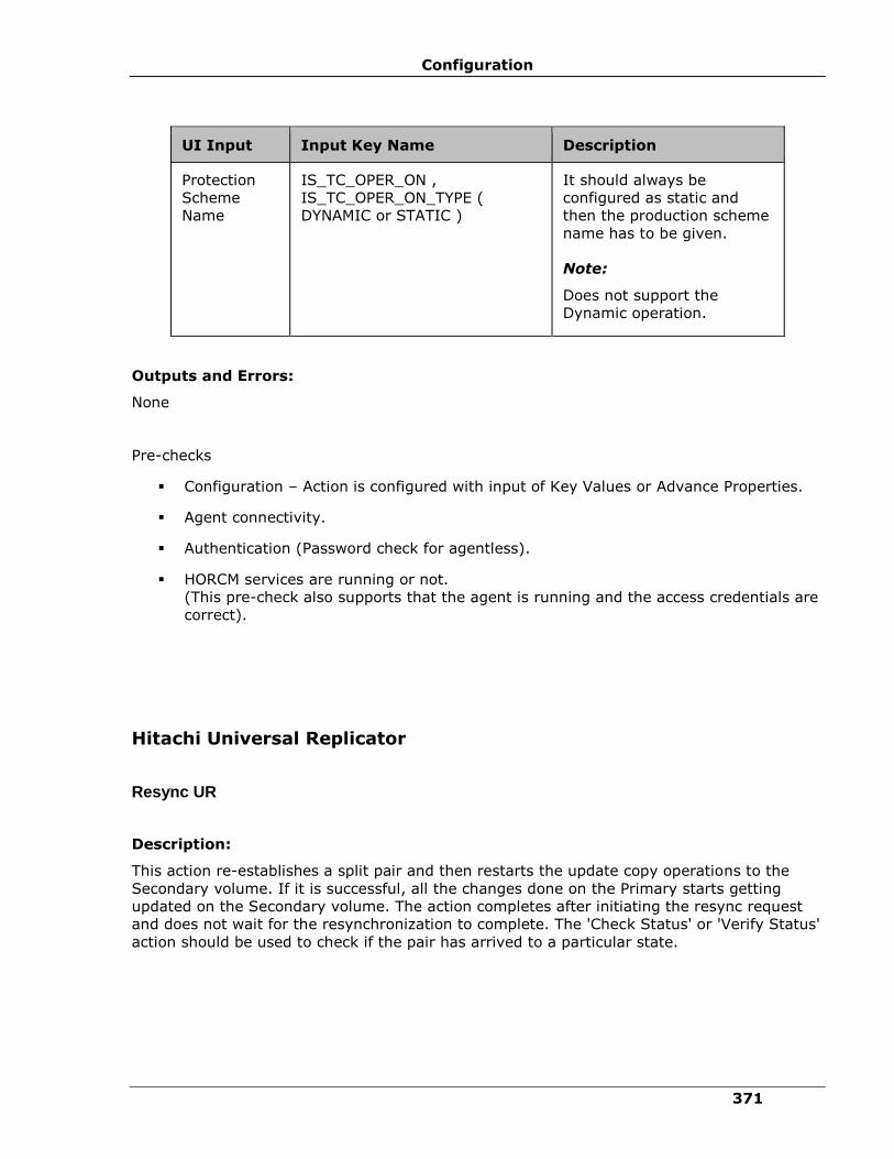
Configuration
371
UI Input Input Key Name Description
Protection
Scheme
Name
IS_TC_OPER_ON ,
IS_TC_OPER_ON_TYPE (
DYNAMIC or STATIC )
It should always be
configured as static and
then the production scheme
name has to be given.
Note:
Does not support the
Dynamic operation.
Outputs and Errors:
None
Pre-checks
▪ Configuration – Action is configured with input of Key Values or Advance Properties.
▪ Agent connectivity.
▪ Authentication (Password check for agentless).
▪ HORCM services are running or not.
(This pre-check also supports that the agent is running and the access credentials are
correct).
Hitachi Universal Replicator
Resync UR
Description:
This action re-establishes a split pair and then restarts the update copy operations to the
Secondary volume. If it is successful, all the changes done on the Primary starts getting
updated on the Secondary volume. The action completes after initiating the resync request
and does not wait for the resynchronization to complete. The 'Check Status' or 'Verify Status'
action should be used to check if the pair has arrived to a particular state.

IBM Resiliency Orchestration Administrator’s Guide
© IBM Corporation 2017 372
When the action is run as a part of the workflow, CCI 'pairresync' command is invoked on the
pair represented by the selected protection scheme, along with the options chosen by the
user. If all the pairs of groups are successfully resynced, the action returns as a success. In
all other cases, it returns as a failure. Success or failure of the action depends on the success
or failure of 'pairresync' command. Refer to Outputs and Errors table below for details.
CCI command: pairresync -g <name>.
Input:
UI Input Input Key Name Description
Protection
Scheme
Name
RESYNC_UR_OPER_ON,
RESYNC_UR_OPER_ON_TYPE
Select the protection scheme
name configured for the
group from the drop-down
list.
Note:
If the group is attached with
more than one pair of
protection subsystem then do
not select "Current
Production Service" or
"Current DR Service".
Instead, select the actual
protection subsystem to
configure the operation.
Outputs and Errors:
The RESYNC_UR_RC key is set with an exit status of 'pairresync' command.
Following are the possible values:
▪ A return code '0' indicates success.
▪ All other values indicates failure.
RESYNC_UR_RC value Description
0 This value indicates that all the pairs in
the group are successfully resynced.
non zero This value indicates some failure in
resync of group.
236 This value indicates an unmatched
volume status within the group.
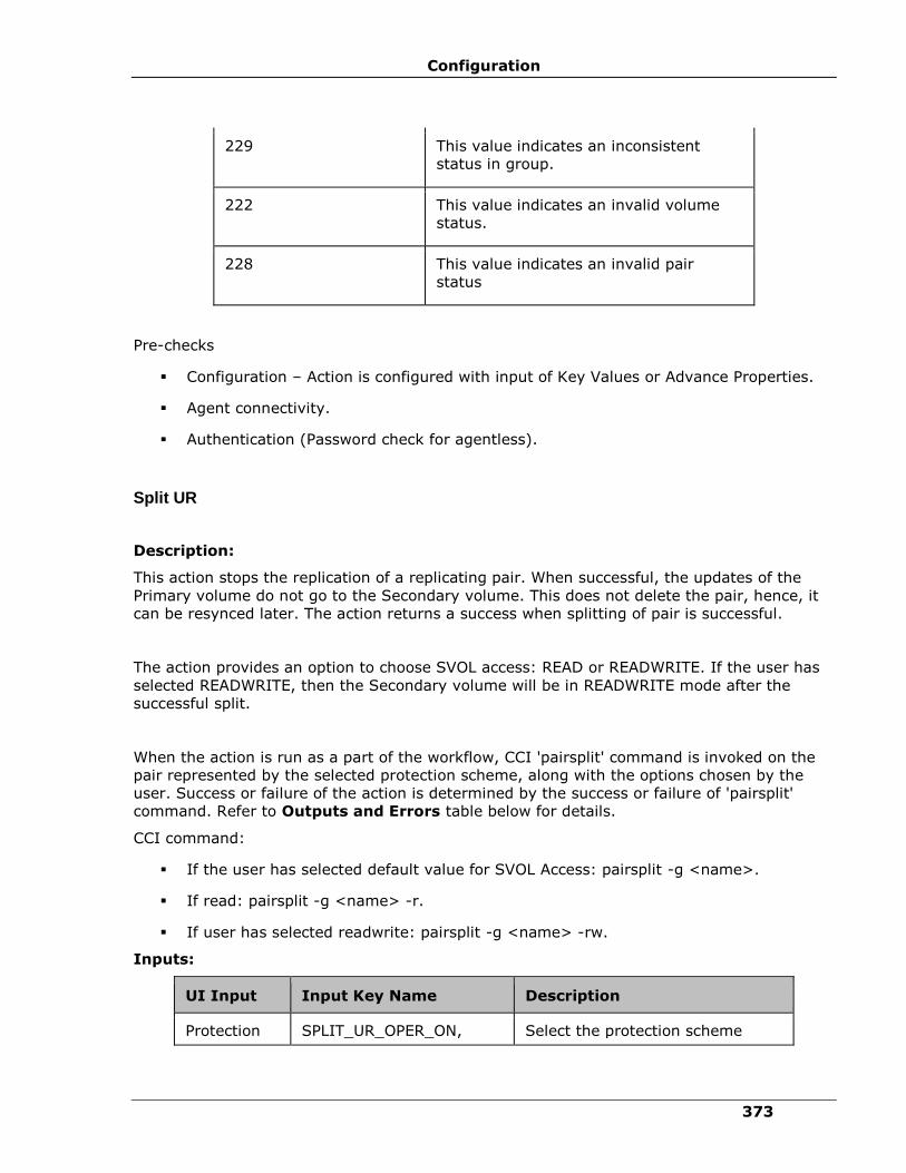
Configuration
373
229 This value indicates an inconsistent
status in group.
222 This value indicates an invalid volume
status.
228 This value indicates an invalid pair
status
Pre-checks
▪ Configuration – Action is configured with input of Key Values or Advance Properties.
▪ Agent connectivity.
▪ Authentication (Password check for agentless).
Split UR
Description:
This action stops the replication of a replicating pair. When successful, the updates of the
Primary volume do not go to the Secondary volume. This does not delete the pair, hence, it
can be resynced later. The action returns a success when splitting of pair is successful.
The action provides an option to choose SVOL access: READ or READWRITE. If the user has
selected READWRITE, then the Secondary volume will be in READWRITE mode after the
successful split.
When the action is run as a part of the workflow, CCI 'pairsplit' command is invoked on the
pair represented by the selected protection scheme, along with the options chosen by the
user. Success or failure of the action is determined by the success or failure of 'pairsplit'
command. Refer to Outputs and Errors table below for details.
CCI command:
▪ If the user has selected default value for SVOL Access: pairsplit -g <name>.
▪ If read: pairsplit -g <name> -r.
▪ If user has selected readwrite: pairsplit -g <name> -rw.
Inputs:
UI Input Input Key Name Description
Protection SPLIT_UR_OPER_ON, Select the protection scheme

IBM Resiliency Orchestration Administrator’s Guide
© IBM Corporation 2017 374
UI Input Input Key Name Description
Scheme
Name
SPLIT_UR_OPER_ON_TYPE name configured for the group
from the drop-down list.
Note:
If the group is attached with more
than one pair of protection
subsystem then do not select
"Current Production Service" or
"Current DR Service". Instead,
select the actual protection
subsystem to configure the
operation.
SVOL
Access
SPLIT_UR_SVOL_ACCESS Select an appropriate option from
the drop-down list. The options
are:
▪ READ
▪ READWRITE
Outputs and Errors:
The SPLIT_UR_RC key is set with an exit status of 'pairsplit' command.
Following are the possible values:
▪ A return code '0' indicates success.
▪ All other values indicates failure.
SPLIT_UR_RC value Description
0 This value indicates that all the
pairs in the group are successfully
suspended.
non zero This value indicates some failure in
splitting of group.
236 This value indicates an unmatched
volume status within the group.

Configuration
375
SPLIT_UR_RC value Description
229 This value indicates an inconsistent
status in group.
222 This value indicates an invalid
volume status.
235 This value indicates a Pair Volume
combination error.
228 This value indicates an invalid pair
status
234 This value indicates a Pair
suspended at WAIT state.
Pre-checks
▪ Configuration – Action is configured with input of Key Values or Advance Properties.
▪ Agent connectivity.
▪ Authentication (Password check for agentless).
Get Status
Description:
This action reports the volume status (whether paired or not paired, and if paired, whether it
is SVol or PVol) and pair status (HP XP specific pair status that indicates the current state of
replication).
When the action is run as a part of the workflow, CCI 'pairvolchk' command is invoked on the
volume represented by the selected protection scheme, along with the options chosen by the
user. Success or failure of the action is determined by the success or failure of 'pairvolchk'
command. Refer to Outputs and Errors table below for details.
CCI command: pairvolchk -g <name>.
Input:
UI Input Input Key Name Description
Protection
Scheme
Name
GET_UR_STATUS_OPER_ON,
GET_UR_STATUS_OPER_ON_TYPE
Select the protection
scheme name
configured for the group
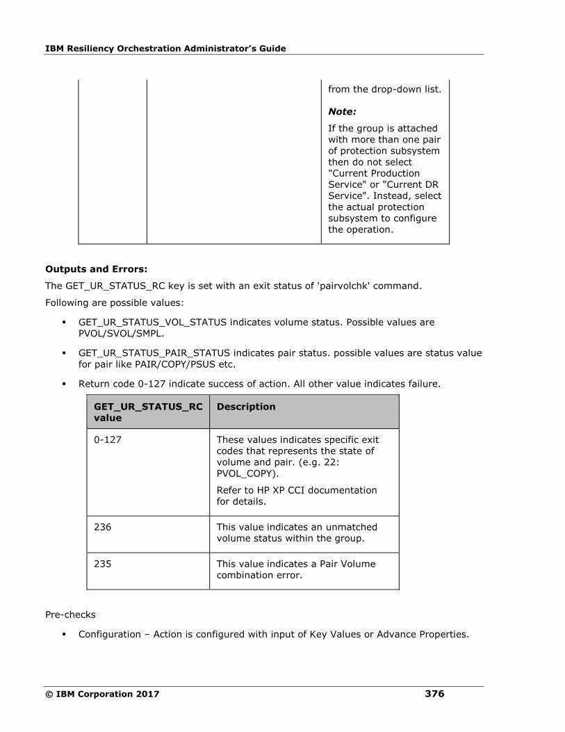
IBM Resiliency Orchestration Administrator’s Guide
© IBM Corporation 2017 376
from the drop-down list.
Note:
If the group is attached
with more than one pair
of protection subsystem
then do not select
"Current Production
Service" or "Current DR
Service". Instead, select
the actual protection
subsystem to configure
the operation.
Outputs and Errors:
The GET_UR_STATUS_RC key is set with an exit status of 'pairvolchk' command.
Following are possible values:
▪ GET_UR_STATUS_VOL_STATUS indicates volume status. Possible values are
PVOL/SVOL/SMPL.
▪ GET_UR_STATUS_PAIR_STATUS indicates pair status. possible values are status value
for pair like PAIR/COPY/PSUS etc.
▪ Return code 0-127 indicate success of action. All other value indicates failure.
GET_UR_STATUS_RC
value
Description
0-127 These values indicates specific exit
codes that represents the state of
volume and pair. (e.g. 22:
PVOL_COPY).
Refer to HP XP CCI documentation
for details.
236 This value indicates an unmatched
volume status within the group.
235 This value indicates a Pair Volume
combination error.
Pre-checks
▪ Configuration – Action is configured with input of Key Values or Advance Properties.
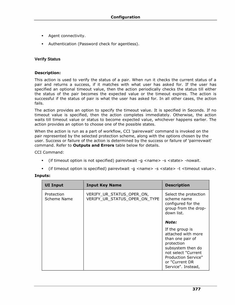
Configuration
377
▪ Agent connectivity.
▪ Authentication (Password check for agentless).
Verify Status
Description:
This action is used to verify the status of a pair. When run it checks the current status of a
pair and returns a success, if it matches with what user has asked for. If the user has
specified an optional timeout value, then the action periodically checks the status till either
the status of the pair becomes the expected value or the timeout expires. The action is
successful if the status of pair is what the user has asked for. In all other cases, the action
fails.
The action provides an option to specify the timeout value. It is specified in Seconds. If no
timeout value is specified, then the action completes immediately. Otherwise, the action
waits till timeout value or status to become expected value, whichever happens earlier. The
action provides an option to choose one of the possible states.
When the action is run as a part of workflow, CCI 'pairevwait' command is invoked on the
pair represented by the selected protection scheme, along with the options chosen by the
user. Success or failure of the action is determined by the success or failure of 'pairrevwait'
command. Refer to Outputs and Errors table below for details.
CCI Command:
▪ (if timeout option is not specified) pairevtwait -g <name> -s <state> -nowait.
▪ (if timeout option is specified) pairevtwait -g <name> -s <state> -t <timeout value>.
Inputs:
UI Input Input Key Name Description
Protection
Scheme Name
VERIFY_UR_STATUS_OPER_ON,
VERIFY_UR_STATUS_OPER_ON_TYPE
Select the protection
scheme name
configured for the
group from the drop-
down list.
Note:
If the group is
attached with more
than one pair of
protection
subsystem then do
not select "Current
Production Service"
or "Current DR
Service". Instead,

IBM Resiliency Orchestration Administrator’s Guide
© IBM Corporation 2017 378
UI Input Input Key Name Description
select the actual
protection
subsystem to
configure the
operation.
Timeout (in
Seconds)Range:0-
1999999
VERIFY_UR_STATUS_TO Enter a numeric
value in seconds.
Replication Group
State
VERIFY_UR_STATUS_STATE Select the replication
group state from the
list of various states.
Outputs and Errors:
The VERIFY_UR_STATUS_RC key is set with an exit status of 'pairevwait' command.
Following are the possible values:
▪ A return code '0' indicates that the action is successful.
▪ All other values indicates failure.
VERIFY_UR_STATUS_RC
value
Description
0 This value indicates that the
current status of pair matches with
the user specified status.
Other than 0-127 This value indicates a failure to get
the current status or current status
does not match with the user
specified value.
236 This value indicates an unmatched
volume status within the group.
229 This value indicates an inconsistent
status in group.
222 This value indicates an invalid
volume status.
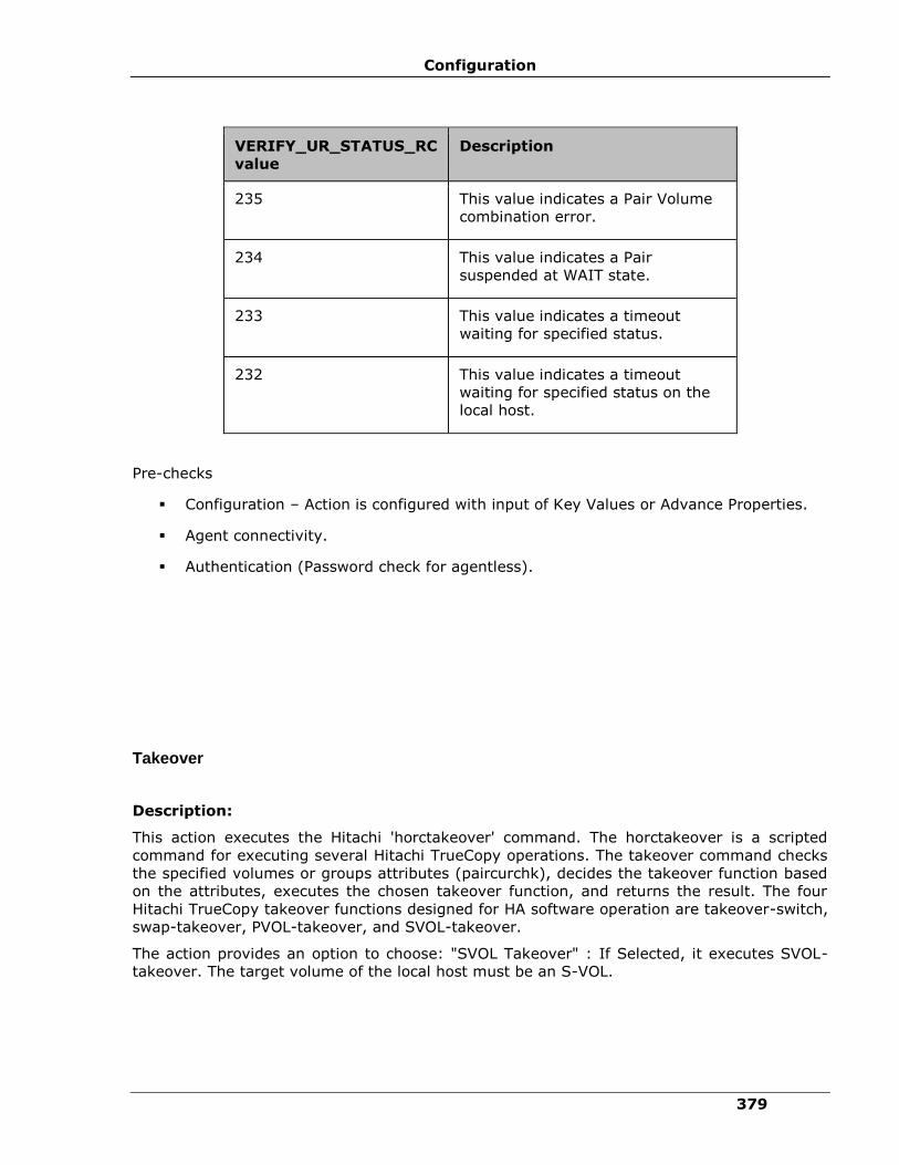
Configuration
379
VERIFY_UR_STATUS_RC
value
Description
235 This value indicates a Pair Volume
combination error.
234 This value indicates a Pair
suspended at WAIT state.
233 This value indicates a timeout
waiting for specified status.
232 This value indicates a timeout
waiting for specified status on the
local host.
Pre-checks
▪ Configuration – Action is configured with input of Key Values or Advance Properties.
▪ Agent connectivity.
▪ Authentication (Password check for agentless).
Takeover
Description:
This action executes the Hitachi 'horctakeover' command. The horctakeover is a scripted
command for executing several Hitachi TrueCopy operations. The takeover command checks
the specified volumes or groups attributes (paircurchk), decides the takeover function based
on the attributes, executes the chosen takeover function, and returns the result. The four
Hitachi TrueCopy takeover functions designed for HA software operation are takeover-switch,
swap-takeover, PVOL-takeover, and SVOL-takeover.
The action provides an option to choose: "SVOL Takeover" : If Selected, it executes SVOL-
takeover. The target volume of the local host must be an S-VOL.

IBM Resiliency Orchestration Administrator’s Guide
© IBM Corporation 2017 380
A group can be specified as the target of the TrueCopy takeover command. If SVOL-takeover
is specified for a group, the data consistency check is executed for all volumes in the group,
and all the inconsistent volumes are found in the execution log file and displayed (same as
paircurchk command). The takeover command allows swapping of the Primary and
Secondary volumes, so that if the Primary or the Secondary volume is switched due to a
server error or package transfer, duplex operations can be continued using the reversed
volumes. When control is handed over to the current node, swapping the volumes again
eliminates the need to copy them. The takeover command also allows the Secondary volume
to be separated for disaster recovery operations.
The takeover command, when activated by a control script, checks the combination of
attributes of the local and remote volumes and determines the proper takeover action.
Various takeover functions that can be executed are Nop-takeover, Swap-takeover, SVOL-
takeover, PVOL-SMPL-takeover, PVOL-PSUE-takeover and SVOL-SSUS-takeover. If the
command fails, the error message and the error code is returned. If the command succeeds,
the return code and the message tells which takeover sub function is executed. To get details
about the horctakeover sub functions and what state cause which function to initiate, please
refer to applicable Command Control Reference guide.
Note
Hitachi horctakeover command many times returns currency error even if the volumes are
consistent. In such cases, takeover action returns failure.User is expected to verify the
volumes before proceeding to next action. For more details, please refer to CCI guide
(paircuchk).
CCI command:
▪ If SVOL takeover option is not selected: horctakeover -g <name> -t timeout.
▪ If SVOL takeover option is selected: horctakeover -g <name> -t timeout -S.
Inputs:
UI Input Input Key Name Description
Protection
Scheme
Name
TAKEOVER_UR_OPER_ON,
TAKEOVER_UR_OPER_ON_TYPE
Select the protection scheme
name configured for the group
from the drop-down list.
Note:
If the group is attached with
more than one pair of protection
subsystem then do not select
"Current Production Service" or
"Current DR Service". Instead,
select the actual protection
subsystem to configure the
operation.
Volume TAKEOVER_UR_VOL_OPTIONS Select SVOL takover from the

Configuration
381
UI Input Input Key Name Description
Option drop-down list.
Timeout (in
Seconds)
TAKEOVER_UR_TO Enter a value in the numeric
field.
Outputs and Errors:
The REPL_TAKEOVER_RC key is set with an exit status of 'horctakeover' command.
Following are the possible values:
▪ Values 0-5 indicates success of action.
▪ All other values indicates failure of action.
REPL_TAKEOVER_RC
value
Description
0 This value indicates a Nop-takeover (no
operation).
1 This value indicates that a Swap-takeover
was successfully executed.
2 This value indicates that a SVOL-takeover
was successfully executed.
3 This value indicates that a PVOL-SMPL-
takeover was successfully executed.
4 This value indicates the following:
▪ PVOL-PSUE-takeover was
successfully executed.
▪ SVOL-SSUS-takeover was
successfully executed. (This value
depends on the microcode level.)
5 This value indicates that a SVOL-SSUS-
takeover was successfully executed. (This
value depends on the microcode level.)
236 This value indicates an unmatched volume
status within the group.

IBM Resiliency Orchestration Administrator’s Guide
© IBM Corporation 2017 382
REPL_TAKEOVER_RC
value
Description
229 This value indicates an inconsistent status in
group.
235 This value indicates a Pair Volume
combination error.
225 This value indicates a S-Vol currency error.
224 This value indicates a Local Volume
currency error.
223 This value indicates a Local and Remote
Volume currency error.
233 This value indicates a timeout waiting for
specified status.
Pre-checks
▪ Configuration – Action is configured with input of Key Values or Advance Properties.
▪ Agent connectivity.
▪ Authentication (Password check for agentless).
Role Switch
Description:
This action re-establishes a split pair in the reverse direction. The Primary volume becomes
the Secondary volume and vice versa. If it is successful, all the changes done on the
Secondary starts getting updated on the Primary volume. The action completes after
reversing the role and initiating the reverse resync request. It does not wait for
resynchronization to complete. The 'Check Status' or 'Verify Status' action should be used to
check if the pair has arrived to a particular state.
When the action is run as a part of the workflow, CCI 'pairresync -swapp or -swaps'
command is invoked on the pair represented by the selected protection scheme, along with
the options chosen by the user. Success or failure of the action is determined by the success
or failure of 'pairresync' command. Refer to Outputs and Errors table below for details.
CCI Command: pairvolchk -g <name> and pairresync -g <name> -swapp.
Input:
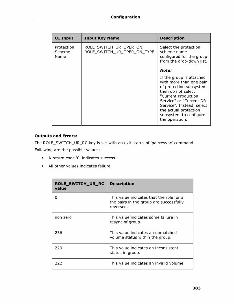
Configuration
383
UI Input Input Key Name Description
Protection
Scheme
Name
ROLE_SWITCH_UR_OPER_ON,
ROLE_SWITCH_UR_OPER_ON_TYPE
Select the protection
scheme name
configured for the group
from the drop-down list.
Note:
If the group is attached
with more than one pair
of protection subsystem
then do not select
"Current Production
Service" or "Current DR
Service". Instead, select
the actual protection
subsystem to configure
the operation.
Outputs and Errors:
The ROLE_SWITCH_UR_RC key is set with an exit status of 'pairresync' command.
Following are the possible values:
▪ A return code '0' indicates success.
▪ All other values indicates failure.
ROLE_SWITCH_UR_RC
value
Description
0 This value indicates that the role for all
the pairs in the group are successfully
reversed.
non zero This value indicates some failure in
resync of group.
236 This value indicates an unmatched
volume status within the group.
229 This value indicates an inconsistent
status in group.
222 This value indicates an invalid volume

IBM Resiliency Orchestration Administrator’s Guide
© IBM Corporation 2017 384
status.
228 This value indicates an invalid pair status
Pre-checks
▪ Configuration – Action is configured with input of Key Values or Advance Properties.
▪ Agent connectivity.
▪ Authentication (Password check for agentless).
Sync Wait
Description:
This action is used to make sure that all the changes on the Primary are updated on the
Secondary volume. The action takes a timeout parameter, that indicates the duration for
which action waits for completion on synchronization. It should be issued after the
application completes its write function and is shutdown or quiesced.
The action provides an option to specify the timeout value for which the action waits for all
the pending transfer to complete. Unit is 100 ms.
When the action is run as a part of the workflow, CCI 'pairsyncwait' command is invoked on
the pair represented by the selected protection scheme, along with the options chosen by the
user. The action is successful if synchronization is complete for the device group. For all
other cases, it fails. Refer to Outputs and Errors table below for details.
CCI Command: pairsyncwait -g <name> -t <timeout>.
Inputs:
UI Input Input Key Name Description
Protection
Scheme
Name
SYNC_WAIT_UR_OPER_ON,
SYNC_WAIT_UR_OPER_ON_TYPE
Select the protection scheme
name configured for the
group from the drop-down
list.
Note:
If the group is attached with
more than one pair of
protection subsystem then do
not select "Current Production
Service" or "Current DR
Service". Instead, select the

Configuration
385
UI Input Input Key Name Description
actual protection subsystem
to configure the operation.
Timeout (in
100ms)
SYNC_WAIT_UR_TO
Enter an appropriate numeral
value.
Outputs and Errors:
The SYNC_WAIT_RC key is set with an exit status of 'pairsyncwait' command.
Following are the possible values:
▪ A return code '0' indicates synchronization is done.
▪ All other values indicates failure.
SYNC_WAIT_UR_RC
value
Description
0 This value indicates that the synchronization is
complete.
1 This value indicates the status as timeout.
2 This value indicates that the Status is broken
(Synchronization process is rejected.)
3 This value indicates that the status is CHANGED
(Q-marker is invalid due to resynchronize).
222 This value indicates an invalid volume status.
Pre-checks
▪ Configuration – Action is configured with input of Key Values or Advance Properties.
▪ Agent connectivity.
▪ Authentication (Password check for agentless).
Check Consistency
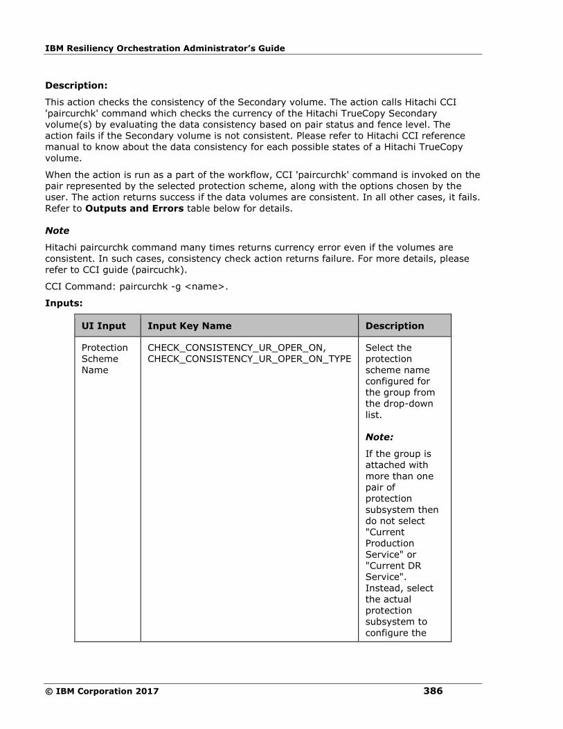
IBM Resiliency Orchestration Administrator’s Guide
© IBM Corporation 2017 386
Description:
This action checks the consistency of the Secondary volume. The action calls Hitachi CCI
'paircurchk' command which checks the currency of the Hitachi TrueCopy Secondary
volume(s) by evaluating the data consistency based on pair status and fence level. The
action fails if the Secondary volume is not consistent. Please refer to Hitachi CCI reference
manual to know about the data consistency for each possible states of a Hitachi TrueCopy
volume.
When the action is run as a part of the workflow, CCI 'paircurchk' command is invoked on the
pair represented by the selected protection scheme, along with the options chosen by the
user. The action returns success if the data volumes are consistent. In all other cases, it fails.
Refer to Outputs and Errors table below for details.
Note
Hitachi paircurchk command many times returns currency error even if the volumes are
consistent. In such cases, consistency check action returns failure. For more details, please
refer to CCI guide (paircuchk).
CCI Command: paircurchk -g <name>.
Inputs:
UI Input Input Key Name Description
Protection
Scheme
Name
CHECK_CONSISTENCY_UR_OPER_ON,
CHECK_CONSISTENCY_UR_OPER_ON_TYPE
Select the
protection
scheme name
configured for
the group from
the drop-down
list.
Note:
If the group is
attached with
more than one
pair of
protection
subsystem then
do not select
"Current
Production
Service" or
"Current DR
Service".
Instead, select
the actual
protection
subsystem to
configure the
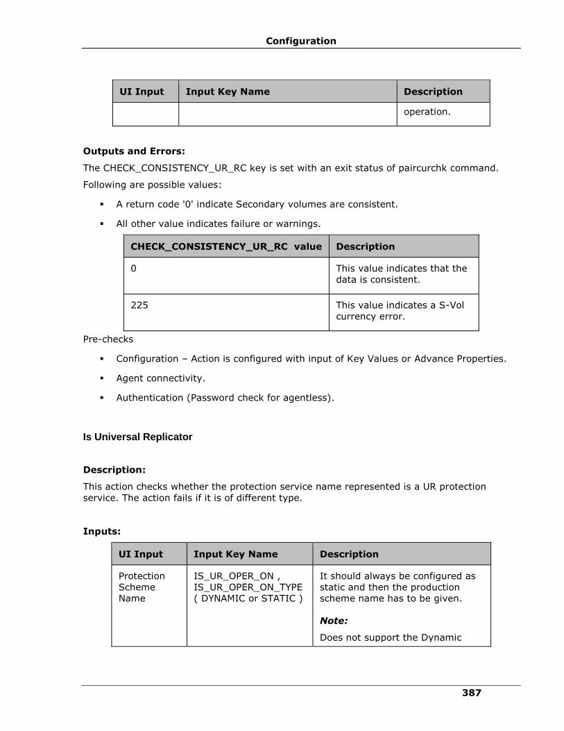
Configuration
387
UI Input Input Key Name Description
operation.
Outputs and Errors:
The CHECK_CONSISTENCY_UR_RC key is set with an exit status of paircurchk command.
Following are possible values:
▪ A return code '0' indicate Secondary volumes are consistent.
▪ All other value indicates failure or warnings.
CHECK_CONSISTENCY_UR_RC value Description
0 This value indicates that the
data is consistent.
225 This value indicates a S-Vol
currency error.
Pre-checks
▪ Configuration – Action is configured with input of Key Values or Advance Properties.
▪ Agent connectivity.
▪ Authentication (Password check for agentless).
Is Universal Replicator
Description:
This action checks whether the protection service name represented is a UR protection
service. The action fails if it is of different type.
Inputs:
UI Input Input Key Name Description
Protection
Scheme
Name
IS_UR_OPER_ON ,
IS_UR_OPER_ON_TYPE
( DYNAMIC or STATIC )
It should always be configured as
static and then the production
scheme name has to be given.
Note:
Does not support the Dynamic
IBM Resiliency Orchestration Administrator’s Guide
© IBM Corporation 2017 388
UI Input Input Key Name Description
operation.
Outputs and Errors:
None
Pre-checks
▪ Configuration – Action is configured with input of Key Values or Advance Properties.
▪ Agent connectivity.
▪ Authentication (Password check for agentless).
Hitachi Shadow Image
Resync ShadowImage
Description:
This action re-establishes a split pair and then restarts the update copy operations to the
Secondary volume. If it is successful, all the changes done on the Primary starts getting
updated on the Secondary volume. The action completes after initiating the resync request
and does not wait for resynchronization to complete. The 'Check Status' or 'Verify Status'
action should be used to check if the pair has arrived to a particular state.
The action provides an option to choose: "resync mode" - quick or normal. If mode is
normal, pairresync will be performed as Non quick mode, regardless of setting of
$HORCC_RSYN environment variable and/or the mode (87) via SVP (Remote console). if
mode = quick, pairresync will be performed as Quick Resync, regardless of setting of
$HORCC_RSYN environment variable and/or the mode (87) via SVP (Remote console). If this
option will not be specified, then performing pairresync is dependent on $HORCC_RSYNC
environment variable and or the mode setting through the SVP (Remote console) whether
the operation of BC is executed by Quick or not. This option is ignored for older version of cci
where -fq option is not supported.
When the action is run as a part of the workflow, CCI 'pairresync' command is invoked on the
pair represented by the selected protection scheme, along with the options chosen by the
user. If all the pairs of groups are successfully resynced, the action returns as a success. In
all other cases, it returns as a failure. Success or failure of the action depends on the success
or failure of 'pairresync' command. Refer to Outputs and Errors table below for details.
CCI command: pairresync -g <name> -fq <normal or quick>.

Configuration
389
Note:
-fq option is ignored for older version of cci where it is not supported.
Inputs:
UI Input Input Key Name Description
Shadow
Image
Name
RESYNC_SI_OPER_ON,
RESYNC_SI_OPER_ON_TYPE
Select the shadow
image name from the
drop-down list.
Resync
Mode
RESYNC_SI_MODE Select an appropriate
option from the drop-
down list. The options
are:
▪ NORMAL
▪ QUICK
Outputs and Errors:
The RESYNC_SI_RC key is set with an exit status of 'pairresync' command.
Following are the possible values:
▪ A return code '0' indicates success.
▪ All other values indicates failure.
RESYNC_SI_RC
value
Description
0 This value indicates that all the
pairs in the group are
successfully resynced.
non zero This value indicates some
failure in resync of group.
236 This value indicates an
unmatched volume status
within the group.
229 This value indicates an
inconsistent status in group.
IBM Resiliency Orchestration Administrator’s Guide
© IBM Corporation 2017 390
222 This value indicates an invalid
volume status.
228 This value indicates an invalid
pair status
Pre-checks
▪ Configuration – Action is configured with input of Key Values or Advance Properties.
▪ Agent connectivity.
▪ Authentication (Password check for agentless).
Split ShadowImage
Description:
This action stops the replication of a replicating pair. When successful, the updates of the
Primary volume does not go to the Secondary volume. This does not delete the pair, hence,
it can be resynced later. The action returns a success when splitting of pair is successful.
When the action is run as a part of the workflow, CCI 'pairsplit' command is invoked on the
pair represented by the selected protection scheme, along with the options chosen by the
user. Success or failure of the action is determined by the success or failure of 'pairsplit'
command. Refer to Outputs and Errors table below for details.
CCI command: pairresync -g <name> -fq <normal or quick>.
Note:
-fq option is ignored for older version of cci where it is not supported.
Inputs:
UI Input Input Key Name Description
Shadow
Image
Name
SPLIT_SI_OPER_ON,
SPLIT_SI_OPER_ON_TYPE
Select the shadow
image name from the
drop-down list.
Split Mode SPLIT_SI_MODE Select an appropriate
option from the drop-

Configuration
391
UI Input Input Key Name Description
down list. The options
are:
▪ NORMAL
▪ QUICK
Outputs and Errors:
The SPLIT_SI_RC key is set with an exit status of 'pairsplit' command.
Following are the possible values:
▪ A return code '0' indicates success.
▪ All other values indicates failure.
SPLIT_SI_RC
value
Description
0 This value indicates that all the pairs in the
group are successfully suspended.
non zero This value indicates some failure in splitting of
group.
236 This value indicates an unmatched volume
status within the group.
229 This value indicates an inconsistent status in
group.
222 This value indicates an invalid volume status.
235 This value indicates a Pair Volume combination
error.
228 This value indicates an invalid pair status
234 This value indicates a Pair suspended at WAIT
state.
Pre-checks
IBM Resiliency Orchestration Administrator’s Guide
© IBM Corporation 2017 392
▪ Configuration – Action is configured with input of Key Values or Advance Properties.
▪ Agent connectivity.
▪ Authentication (Password check for agentless).
Get Status
Description:
This action reports the volume status (whether paired or not paired, and if paired, whether it
is SVol or PVol) and pair status (Hitachi specific pair status that indicates the current state of
replication).
When the action is run as a part of workflow, CCI 'pairvolchk' command is invoked on the
volume represented by the selected protection scheme, along with the options chosen by the
user. Success or failure of the action is determined by the success or failure of 'pairvolchk'
command. Refer to Outputs and Errors table below for details.
CCI command: pairvolchk -g <name>.
Input:
UI Input Input Key Name Description
Shadow
Image
Name
GET_SI_STATUS_OPER_ON,
GET_SI_STATUS_OPER_ON_TYPE
Select the shadow
image name from the
drop-down list.
Outputs and Errors:
The GET_SI_STATUS_RC key is set with an exit status of 'pairvolchk' command.
Following are possible values:
▪ GET_SI_STATUS_VOL_STATUS indicates volume status. Possible values are
PVOL/SVOL/SMPL.
▪ GET_SI_STATUS_PAIR_STATUS indicates pair status. Possible values are status value
for pair like PAIR/COPY/PSUS etc.
▪ Return code 0-127 indicate success of action. All other value indicates failure.
GET_SI_STATUS_RC
value
Description
0-127 These values indicates specific exit codes that represents
the state of volume and pair. (e.g. 22: PVOL_COPY).
Configuration
393
Refer to Hitachi CCI documentation for details.
236 This value indicates an unmatched volume status within
the group.
235 This value indicates a Pair Volume combination error.
Pre-checks
▪ Configuration – Action is configured with input of Key Values or Advance Properties.
▪ Agent connectivity.
▪ Authentication (Password check for agentless).
Verify Status
Description:
This action is used to verify the status of a pair. When run it checks the current status of a
pair and returns a success, if it matches with what user has asked for. If the user has
specified an optional timeout value, then the action periodically checks the status till either
the status of pair becomes the expected value or timeout expires. The action is successful if
the status of pair is what user has asked for. In all other cases, the action fails.
The action provides an option to specify the timeout value. It is specified in Seconds. If no
timeout value is specified, then the action completes immediately. Otherwise, the action
waits till timeout value or status to become expected value, whichever happens earlier. The
action provides an option to choose one of the possible states.
When the action is run as a part of the workflow, CCI 'pairevwait' command is invoked on the
pair represented by the selected protection scheme, along with the options chosen by the
user. Success or failure of the action is determined by the success or failure of 'pairevwait'
command. Refer to Outputs and Errors table below for details.
CCI Command:
▪ (if timeout option is not specified) pairevtwait -g <name> -s <state> -nowait.
▪ (if timeout option is specified) pairevtwait -g <name> -s <state> -t <timeout value>.
Inputs:
UI Input Input Key Name Description
Shadow
Image
VERIFY_SI_STATUS_OPER_ON,
VERIFY_SI_STATUS_OPER_ON_TYPE
Select the shadow image
name from the drop-down

IBM Resiliency Orchestration Administrator’s Guide
© IBM Corporation 2017 394
UI Input Input Key Name Description
Name list.
Timeout (in
Seconds)
Range:0-
1999999
VERIFY_SI_STATUS_TO Enter a numeric value in
seconds.
Replication
Group
State
VERIFY_SI_STATUS_STATE Select the replication group
state from the list of
various states.
Outputs and Errors:
The VERIFY_SI_STATUS_RC key is set with an exit status of 'pairevwait' command.
Following are the possible values:
▪ A return code '0' indicates that the action is successful.
▪ All other values indicates failure.
VERIFY_SI_STATUS_RC
value
Description
0 This value indicates that the current status
of pair matches with the user specified
status.
Other than 0-127 This value indicates a failure to get the
current status or current status does not
match with the user specified value.
236 This value indicates an unmatched volume
status within the group.
229 This value indicates an inconsistent status
in group.
222 This value indicates an invalid volume
status.
235 This value indicates a Pair Volume

Configuration
395
VERIFY_SI_STATUS_RC
value
Description
combination error.
234 This value indicates a Pair suspended at
WAIT state.
233 This value indicates a timeout waiting for
specified status.
232 This value indicates a timeout waiting for
specified status on the local host.
Pre-checks
▪ Configuration – Action is configured with input of Key Values or Advance Properties.
▪ Agent connectivity.
▪ Authentication (Password check for agentless).
Delete ShadowImage
Description:
This action deletes the replication relationship between the Primary volume and the
Secondary volume. The user cannot resync the delta changes between the Primary and the
Secondary volume once it is deleted.
When the action is run as a part of the workflow, CCI 'pairsplit -S' command is invoked on
the pair represented by the selected protection scheme, along with the options chosen by the
user. Success or failure of the action is determined by the success or failure of 'pairsplit'
command. Refer to Outputs and Errors table below for details.
CCI Command: pairsplit -g <name> -S.
Inputs:
UI Input Input Key Name Description
Shadow
Image
Name
DELETE_SI_OPER_ON,
DELETE_SI_OPER_ON_TYPE
Select the shadow image
name from the drop-down
list.
Outputs and Errors:

IBM Resiliency Orchestration Administrator’s Guide
© IBM Corporation 2017 396
The DELETE_SI_RC key is set with an exit status of 'pairsplit' command.
Following are the possible values:
▪ A return code '0' indicates success.
▪ All other values indicates failure.
DELETE_SI_RC value Description
0 This value indicates that the
replication group is successfully
deleted.
non zero This value indicates some failure in
splitting of group.
236 This value indicates an unmatched
volume status within the group.
229 This value indicates an inconsistent
status in group.
222 This value indicates an invalid volume
status.
235 This value indicates a Pair Volume
combination error.
228 This value indicates an invalid pair
status
234 This value indicates a Pair suspended
at WAIT state.
Pre-checks
▪ Configuration – Action is configured with input of Key Values or Advance Properties.
▪ Agent connectivity.
▪ Authentication (Password check for agentless).

Configuration
397
Create ShadowImage
Description:
This action creates the replication relationship between the Primary volume and the
Secondary volume. The action returns after the initial copy is initiated between the Primary
and the Secondary Volumes. The user should verify the Replica status to check the desired
status. The replication properties, such as, type of replication (sync/async) or fence level
(Data/status etc) would be the same as per the setting present while discovering protection
scheme or default values.
The action provides an option to choose the direction of replication: It can be forward
(Selected protection scheme as Primary) or reverse (selected protection scheme as
Secondary).
When the action is run as a part of the workflow, CCI 'paircreate' command is invoked on the
pair represented by the selected protection scheme, along with the options present while
discovery of object. Success or failure of the action is determined by the success or failure of
'paircreate' command. Refer to Outputs and Errors table below for details.
CCI Command: paircreate -g <name> -vl (if user has selected FORWARD option) or -vr (if
user has selected REVERSE option).
Inputs:
UI Input Input Key Name Description
Shadow
Image
Name
CREATE_SI_OPER_ON,
CREATE_SI_OPER_ON_TYPE
Select the shadow image
name from the drop-down
list.
Replication
Direction
CREATE_SI_REPL_DIRECTION Select Forward or Reverse
from the drop-down list.
Outputs and Errors:
The CREATE_SI_RC key is set with an exit status of 'paircreate' command.
Following are the possible values:
▪ A return code '0' indicates success.
▪ All other values indicates failure.
CREATE_SI_RC
value
Description
0 This value indicates that the replication
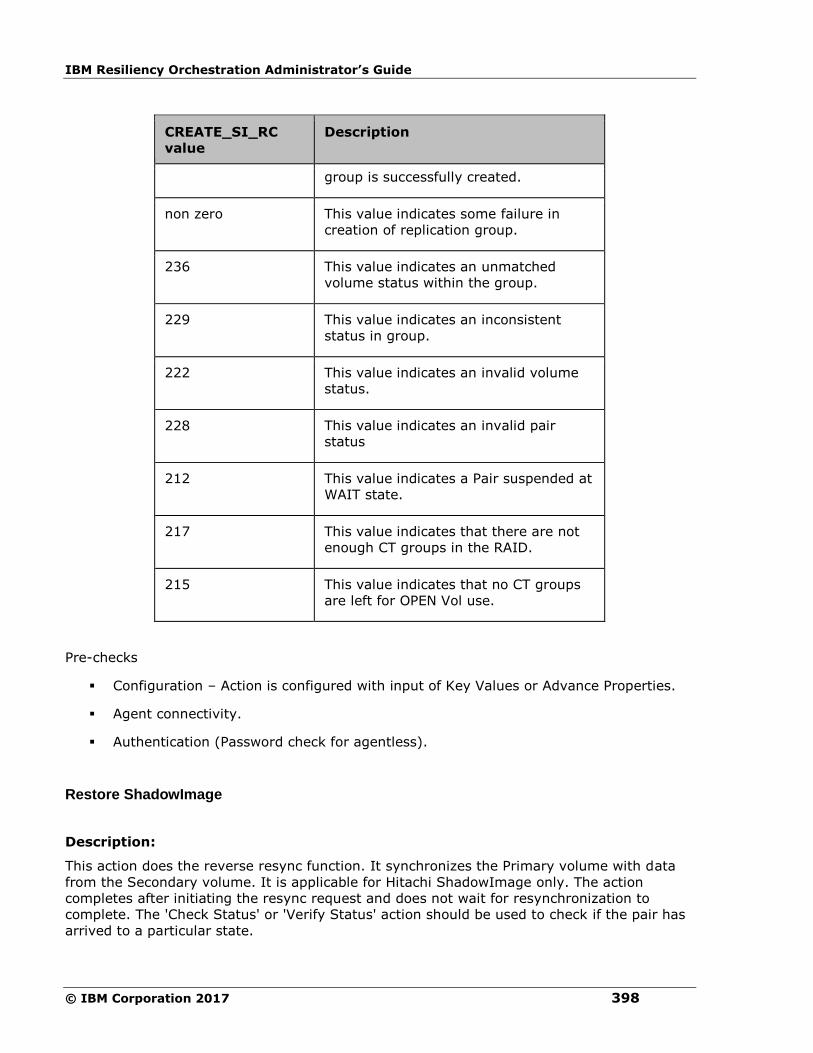
IBM Resiliency Orchestration Administrator’s Guide
© IBM Corporation 2017 398
CREATE_SI_RC
value
Description
group is successfully created.
non zero This value indicates some failure in
creation of replication group.
236 This value indicates an unmatched
volume status within the group.
229 This value indicates an inconsistent
status in group.
222 This value indicates an invalid volume
status.
228 This value indicates an invalid pair
status
212 This value indicates a Pair suspended at
WAIT state.
217 This value indicates that there are not
enough CT groups in the RAID.
215 This value indicates that no CT groups
are left for OPEN Vol use.
Pre-checks
▪ Configuration – Action is configured with input of Key Values or Advance Properties.
▪ Agent connectivity.
▪ Authentication (Password check for agentless).
Restore ShadowImage
Description:
This action does the reverse resync function. It synchronizes the Primary volume with data
from the Secondary volume. It is applicable for Hitachi ShadowImage only. The action
completes after initiating the resync request and does not wait for resynchronization to
complete. The 'Check Status' or 'Verify Status' action should be used to check if the pair has
arrived to a particular state.
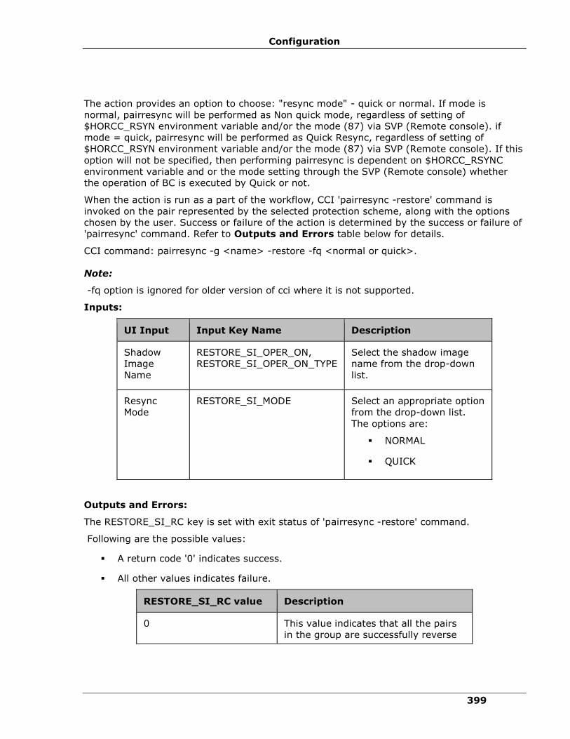
Configuration
399
The action provides an option to choose: "resync mode" - quick or normal. If mode is
normal, pairresync will be performed as Non quick mode, regardless of setting of
$HORCC_RSYN environment variable and/or the mode (87) via SVP (Remote console). if
mode = quick, pairresync will be performed as Quick Resync, regardless of setting of
$HORCC_RSYN environment variable and/or the mode (87) via SVP (Remote console). If this
option will not be specified, then performing pairresync is dependent on $HORCC_RSYNC
environment variable and or the mode setting through the SVP (Remote console) whether
the operation of BC is executed by Quick or not.
When the action is run as a part of the workflow, CCI 'pairresync -restore' command is
invoked on the pair represented by the selected protection scheme, along with the options
chosen by the user. Success or failure of the action is determined by the success or failure of
'pairresync' command. Refer to Outputs and Errors table below for details.
CCI command: pairresync -g <name> -restore -fq <normal or quick>.
Note:
-fq option is ignored for older version of cci where it is not supported.
Inputs:
UI Input Input Key Name Description
Shadow
Image
Name
RESTORE_SI_OPER_ON,
RESTORE_SI_OPER_ON_TYPE
Select the shadow image
name from the drop-down
list.
Resync
Mode
RESTORE_SI_MODE Select an appropriate option
from the drop-down list.
The options are:
▪ NORMAL
▪ QUICK
Outputs and Errors:
The RESTORE_SI_RC key is set with exit status of 'pairresync -restore' command.
Following are the possible values:
▪ A return code '0' indicates success.
▪ All other values indicates failure.
RESTORE_SI_RC value Description
0 This value indicates that all the pairs
in the group are successfully reverse

IBM Resiliency Orchestration Administrator’s Guide
© IBM Corporation 2017 400
RESTORE_SI_RC value Description
resynced.
non zero This value indicates some failure in
resync of group.
236 This value indicates an unmatched
volume status within the group.
229 This value indicates an inconsistent
status in group.
222 This value indicates an invalid volume
status.
228 This value indicates an invalid pair
status
Pre-checks
▪ Configuration – Action is configured with input of Key Values or Advance Properties.
▪ Agent connectivity.
▪ Authentication (Password check for agentless).
Is Shadow Image
Description:
This action checks whether the protection service name represented is a Shadow Image
protection service. The action fails if it is of different type.
Inputs:
UI Input Input Key Name Description
Protection
Scheme
Name
IS_SI_OPER_ON ,
IS_SI_OPER_ON_TYPE (
DYNAMIC or STATIC )
It should always be configured as
static and then the production scheme
name has to be given.
Note:
Does not support the Dynamic
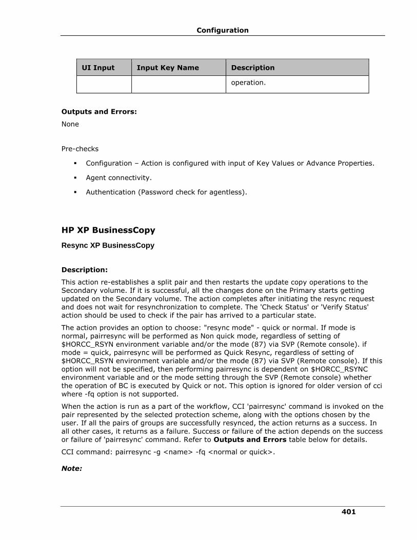
Configuration
401
UI Input Input Key Name Description
operation.
Outputs and Errors:
None
Pre-checks
▪ Configuration – Action is configured with input of Key Values or Advance Properties.
▪ Agent connectivity.
▪ Authentication (Password check for agentless).
HP XP BusinessCopy
Resync XP BusinessCopy
Description:
This action re-establishes a split pair and then restarts the update copy operations to the
Secondary volume. If it is successful, all the changes done on the Primary starts getting
updated on the Secondary volume. The action completes after initiating the resync request
and does not wait for resynchronization to complete. The 'Check Status' or 'Verify Status'
action should be used to check if the pair has arrived to a particular state.
The action provides an option to choose: "resync mode" - quick or normal. If mode is
normal, pairresync will be performed as Non quick mode, regardless of setting of
$HORCC_RSYN environment variable and/or the mode (87) via SVP (Remote console). if
mode = quick, pairresync will be performed as Quick Resync, regardless of setting of
$HORCC_RSYN environment variable and/or the mode (87) via SVP (Remote console). If this
option will not be specified, then performing pairresync is dependent on $HORCC_RSYNC
environment variable and or the mode setting through the SVP (Remote console) whether
the operation of BC is executed by Quick or not. This option is ignored for older version of cci
where -fq option is not supported.
When the action is run as a part of the workflow, CCI 'pairresync' command is invoked on the
pair represented by the selected protection scheme, along with the options chosen by the
user. If all the pairs of groups are successfully resynced, the action returns as a success. In
all other cases, it returns as a failure. Success or failure of the action depends on the success
or failure of 'pairresync' command. Refer to Outputs and Errors table below for details.
CCI command: pairresync -g <name> -fq <normal or quick>.
Note:
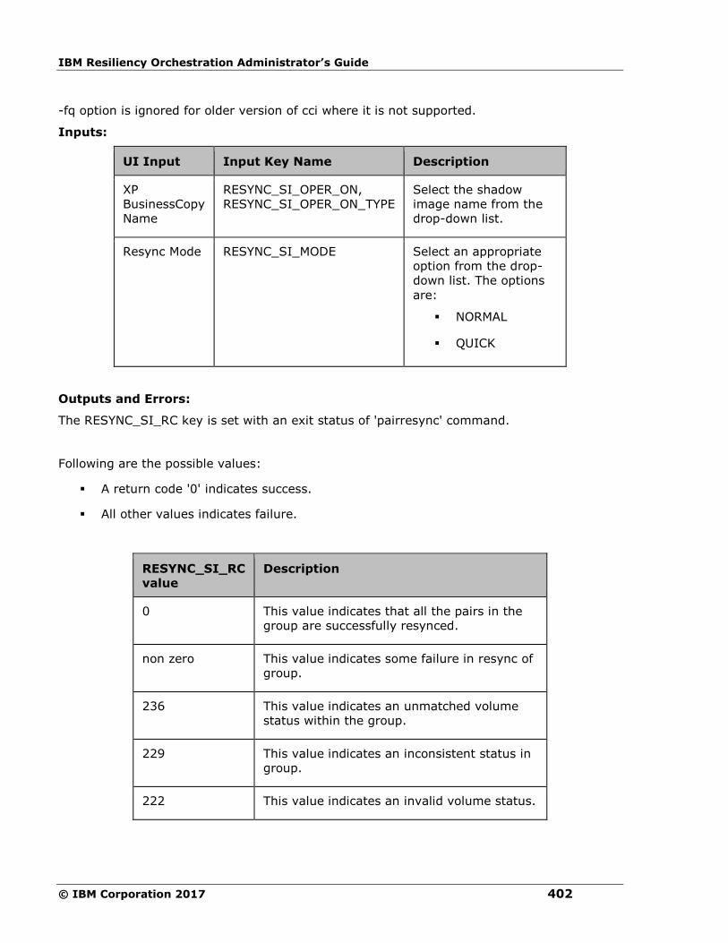
IBM Resiliency Orchestration Administrator’s Guide
© IBM Corporation 2017 402
-fq option is ignored for older version of cci where it is not supported.
Inputs:
UI Input Input Key Name Description
XP
BusinessCopy
Name
RESYNC_SI_OPER_ON,
RESYNC_SI_OPER_ON_TYPE
Select the shadow
image name from the
drop-down list.
Resync Mode RESYNC_SI_MODE Select an appropriate
option from the drop-
down list. The options
are:
▪ NORMAL
▪ QUICK
Outputs and Errors:
The RESYNC_SI_RC key is set with an exit status of 'pairresync' command.
Following are the possible values:
▪ A return code '0' indicates success.
▪ All other values indicates failure.
RESYNC_SI_RC
value
Description
0 This value indicates that all the pairs in the
group are successfully resynced.
non zero This value indicates some failure in resync of
group.
236 This value indicates an unmatched volume
status within the group.
229 This value indicates an inconsistent status in
group.
222 This value indicates an invalid volume status.

Configuration
403
RESYNC_SI_RC
value
Description
228 This value indicates an invalid pair status.
Pre-checks
▪ Configuration – Action is configured with input of Key Values or Advance Properties.
▪ Agent connectivity.
▪ Authentication (Password check for agentless).
Split XP BusinessCopy
Description:
This action stops the replication of a replicating pair. When successful, the updates of the
Primary volume does not go to the Secondary volume. This does not delete the pair, hence,
it can be resynced later. The action returns a success when splitting of pair is successful.
When the action is run as a part of the workflow, CCI 'pairsplit' command is invoked on the
pair represented by the selected protection scheme, along with the options chosen by the
user. Success or failure of the action is determined by the success or failure of 'pairsplit'
command. Refer to Outputs and Errors table below for details.
CCI command: pairresync -g <name> -fq <normal or quick>.
Note:
-fq option is ignored for older version of cci where it is not supported.
Inputs:
UI Input Input Key Name Description
XP
BusinessCopy
Name
SPLIT_SI_OPER_ON,
SPLIT_SI_OPER_ON_TYPE
Select the shadow
image name from the
drop-down list.
Split Mode SPLIT_SI_MODE Select an appropriate
option from the drop-
down list. The options
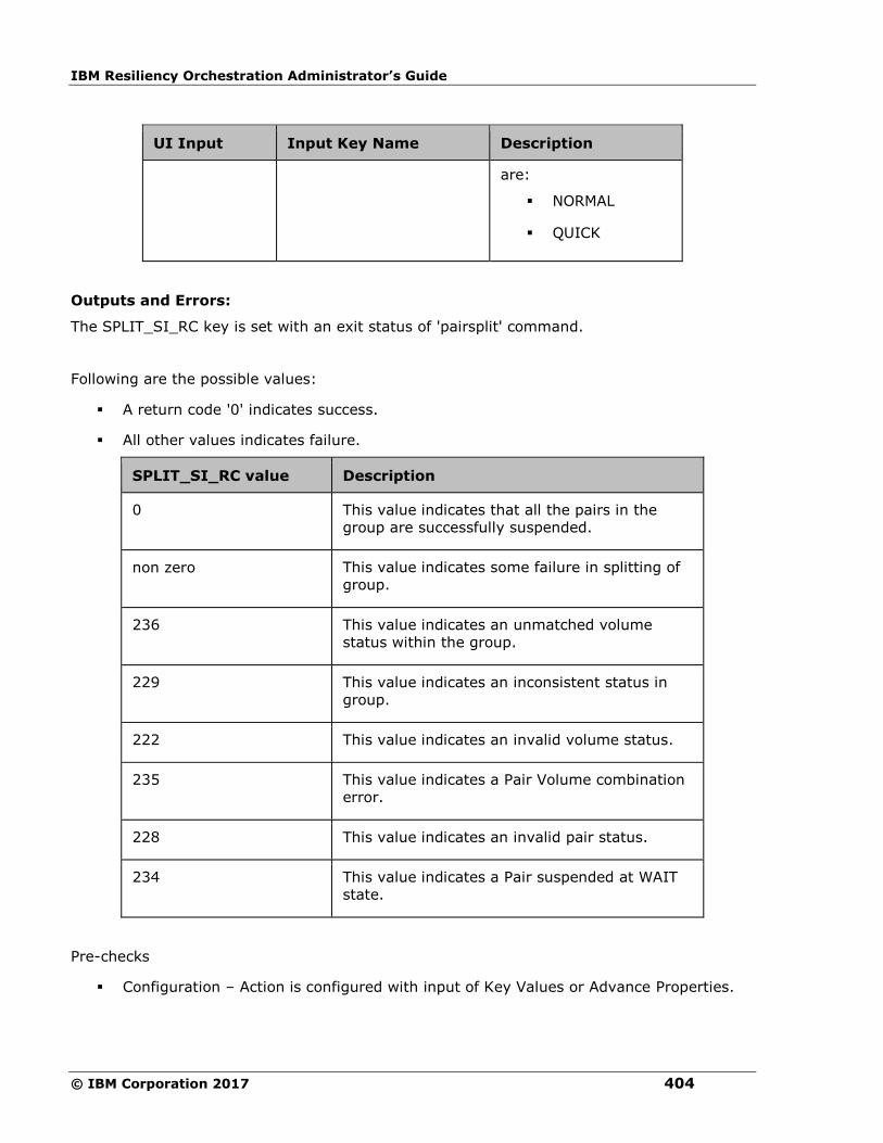
IBM Resiliency Orchestration Administrator’s Guide
© IBM Corporation 2017 404
UI Input Input Key Name Description
are:
▪ NORMAL
▪ QUICK
Outputs and Errors:
The SPLIT_SI_RC key is set with an exit status of 'pairsplit' command.
Following are the possible values:
▪ A return code '0' indicates success.
▪ All other values indicates failure.
SPLIT_SI_RC value Description
0 This value indicates that all the pairs in the
group are successfully suspended.
non zero This value indicates some failure in splitting of
group.
236 This value indicates an unmatched volume
status within the group.
229 This value indicates an inconsistent status in
group.
222 This value indicates an invalid volume status.
235 This value indicates a Pair Volume combination
error.
228 This value indicates an invalid pair status.
234 This value indicates a Pair suspended at WAIT
state.
Pre-checks
▪ Configuration – Action is configured with input of Key Values or Advance Properties.
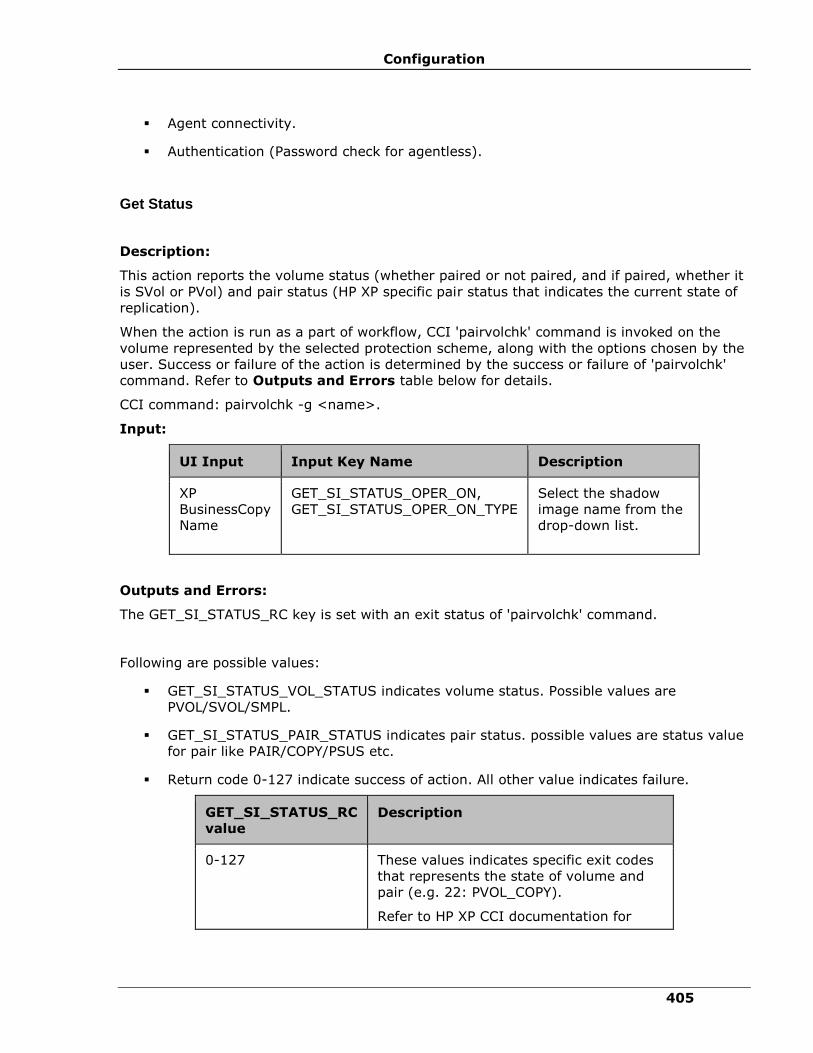
Configuration
405
▪ Agent connectivity.
▪ Authentication (Password check for agentless).
Get Status
Description:
This action reports the volume status (whether paired or not paired, and if paired, whether it
is SVol or PVol) and pair status (HP XP specific pair status that indicates the current state of
replication).
When the action is run as a part of workflow, CCI 'pairvolchk' command is invoked on the
volume represented by the selected protection scheme, along with the options chosen by the
user. Success or failure of the action is determined by the success or failure of 'pairvolchk'
command. Refer to Outputs and Errors table below for details.
CCI command: pairvolchk -g <name>.
Input:
UI Input Input Key Name Description
XP
BusinessCopy
Name
GET_SI_STATUS_OPER_ON,
GET_SI_STATUS_OPER_ON_TYPE
Select the shadow
image name from the
drop-down list.
Outputs and Errors:
The GET_SI_STATUS_RC key is set with an exit status of 'pairvolchk' command.
Following are possible values:
▪ GET_SI_STATUS_VOL_STATUS indicates volume status. Possible values are
PVOL/SVOL/SMPL.
▪ GET_SI_STATUS_PAIR_STATUS indicates pair status. possible values are status value
for pair like PAIR/COPY/PSUS etc.
▪ Return code 0-127 indicate success of action. All other value indicates failure.
GET_SI_STATUS_RC
value Description
0-127 These values indicates specific exit codes
that represents the state of volume and
pair (e.g. 22: PVOL_COPY).
Refer to HP XP CCI documentation for

IBM Resiliency Orchestration Administrator’s Guide
© IBM Corporation 2017 406
GET_SI_STATUS_RC
value
Description
details.
236 This value indicates an unmatched volume
status within the group.
235 This value indicates a Pair Volume
combination error.
Pre-checks
▪ Configuration – Action is configured with input of Key Values or Advance Properties.
▪ Agent connectivity.
▪ Authentication (Password check for agentless).
Verify Status
Description:
This action is used to verify the status of a pair. When run it checks the current status of a
pair and returns a success, if it matches with what user has asked for. If the user has
specified an optional timeout value, then the action periodically checks the status till either
the status of pair becomes the expected value or timeout expires. The action is successful if
the status of pair is what user has asked for. In all other cases, the action fails.
The action provides an option to specify the timeout value. It is specified in Seconds. If no
timeout value is specified, then the action completes immediately. Otherwise, the action
waits till timeout value or status to become expected value, whichever happens earlier. The
action provides an option to choose one of the possible states.
When the action is run as a part of the workflow, CCI 'pairevwait' command is invoked on the
pair represented by the selected protection scheme, along with the options chosen by the
user. Success or failure of the action is determined by the success or failure of 'pairevwait'
command. Refer to Outputs and Errors table below for details.
CCI Command:
▪ (if timeout option is not specified) pairevtwait -g <name> -s <state> -nowait.
▪ (if timeout option is specified) pairevtwait -g <name> -s <state> -t <timeout value>.
Inputs:
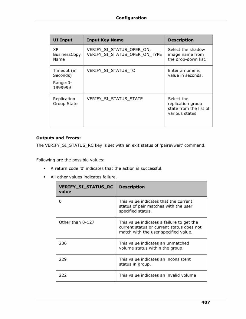
Configuration
407
UI Input Input Key Name Description
XP
BusinessCopy
Name
VERIFY_SI_STATUS_OPER_ON,
VERIFY_SI_STATUS_OPER_ON_TYPE
Select the shadow
image name from
the drop-down list.
Timeout (in
Seconds)
Range:0-
1999999
VERIFY_SI_STATUS_TO Enter a numeric
value in seconds.
Replication
Group State
VERIFY_SI_STATUS_STATE Select the
replication group
state from the list of
various states.
Outputs and Errors:
The VERIFY_SI_STATUS_RC key is set with an exit status of 'pairevwait' command.
Following are the possible values:
▪ A return code '0' indicates that the action is successful.
▪ All other values indicates failure.
VERIFY_SI_STATUS_RC
value Description
0 This value indicates that the current
status of pair matches with the user
specified status.
Other than 0-127 This value indicates a failure to get the
current status or current status does not
match with the user specified value.
236 This value indicates an unmatched
volume status within the group.
229 This value indicates an inconsistent
status in group.
222 This value indicates an invalid volume
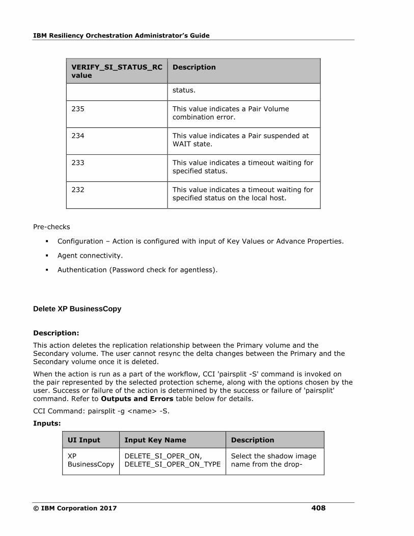
IBM Resiliency Orchestration Administrator’s Guide
© IBM Corporation 2017 408
VERIFY_SI_STATUS_RC
value
Description
status.
235 This value indicates a Pair Volume
combination error.
234 This value indicates a Pair suspended at
WAIT state.
233 This value indicates a timeout waiting for
specified status.
232 This value indicates a timeout waiting for
specified status on the local host.
Pre-checks
▪ Configuration – Action is configured with input of Key Values or Advance Properties.
▪ Agent connectivity.
▪ Authentication (Password check for agentless).
Delete XP BusinessCopy
Description:
This action deletes the replication relationship between the Primary volume and the
Secondary volume. The user cannot resync the delta changes between the Primary and the
Secondary volume once it is deleted.
When the action is run as a part of the workflow, CCI 'pairsplit -S' command is invoked on
the pair represented by the selected protection scheme, along with the options chosen by the
user. Success or failure of the action is determined by the success or failure of 'pairsplit'
command. Refer to Outputs and Errors table below for details.
CCI Command: pairsplit -g <name> -S.
Inputs:
UI Input Input Key Name Description
XP
BusinessCopy
DELETE_SI_OPER_ON,
DELETE_SI_OPER_ON_TYPE
Select the shadow image
name from the drop-
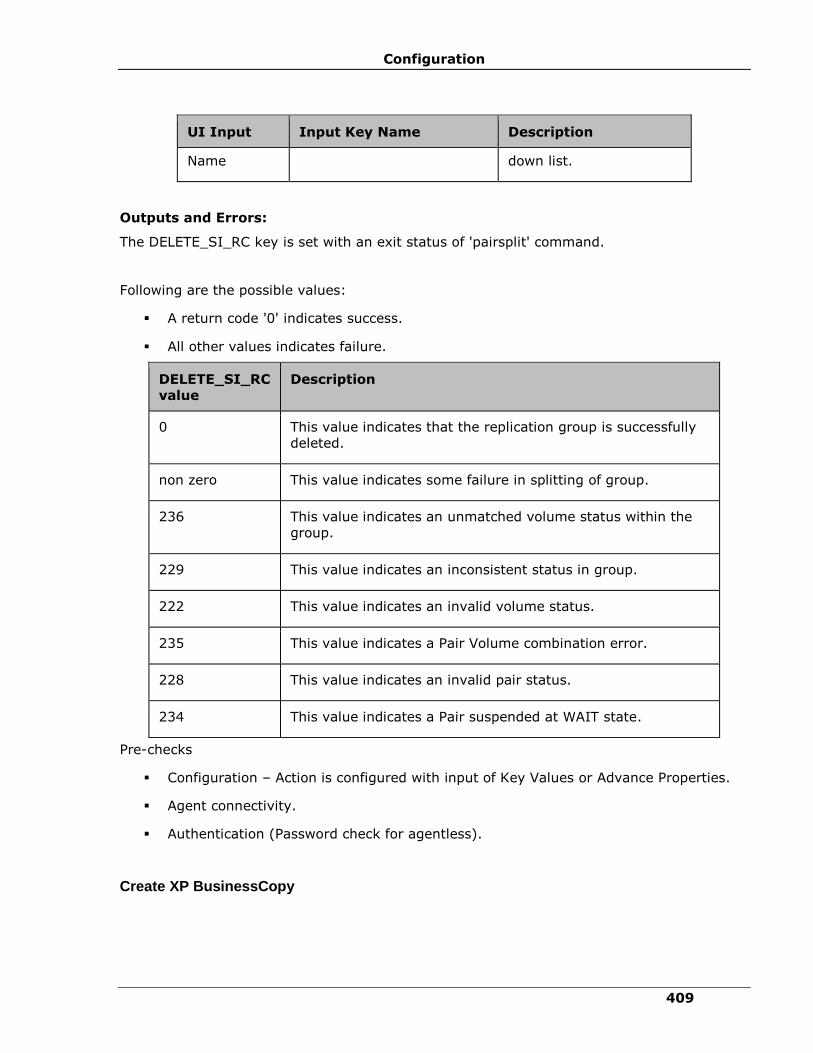
Configuration
409
UI Input Input Key Name Description
Name down list.
Outputs and Errors:
The DELETE_SI_RC key is set with an exit status of 'pairsplit' command.
Following are the possible values:
▪ A return code '0' indicates success.
▪ All other values indicates failure.
DELETE_SI_RC
value
Description
0 This value indicates that the replication group is successfully
deleted.
non zero This value indicates some failure in splitting of group.
236 This value indicates an unmatched volume status within the
group.
229 This value indicates an inconsistent status in group.
222 This value indicates an invalid volume status.
235 This value indicates a Pair Volume combination error.
228 This value indicates an invalid pair status.
234 This value indicates a Pair suspended at WAIT state.
Pre-checks
▪ Configuration – Action is configured with input of Key Values or Advance Properties.
▪ Agent connectivity.
▪ Authentication (Password check for agentless).
Create XP BusinessCopy
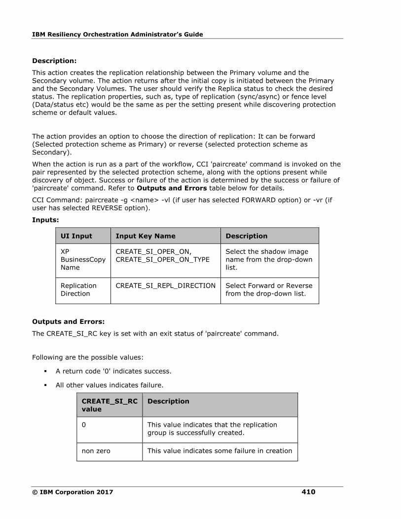
IBM Resiliency Orchestration Administrator’s Guide
© IBM Corporation 2017 410
Description:
This action creates the replication relationship between the Primary volume and the
Secondary volume. The action returns after the initial copy is initiated between the Primary
and the Secondary Volumes. The user should verify the Replica status to check the desired
status. The replication properties, such as, type of replication (sync/async) or fence level
(Data/status etc) would be the same as per the setting present while discovering protection
scheme or default values.
The action provides an option to choose the direction of replication: It can be forward
(Selected protection scheme as Primary) or reverse (selected protection scheme as
Secondary).
When the action is run as a part of the workflow, CCI 'paircreate' command is invoked on the
pair represented by the selected protection scheme, along with the options present while
discovery of object. Success or failure of the action is determined by the success or failure of
'paircreate' command. Refer to Outputs and Errors table below for details.
CCI Command: paircreate -g <name> -vl (if user has selected FORWARD option) or -vr (if
user has selected REVERSE option).
Inputs:
UI Input Input Key Name Description
XP
BusinessCopy
Name
CREATE_SI_OPER_ON,
CREATE_SI_OPER_ON_TYPE
Select the shadow image
name from the drop-down
list.
Replication
Direction
CREATE_SI_REPL_DIRECTION Select Forward or Reverse
from the drop-down list.
Outputs and Errors:
The CREATE_SI_RC key is set with an exit status of 'paircreate' command.
Following are the possible values:
▪ A return code '0' indicates success.
▪ All other values indicates failure.
CREATE_SI_RC
value
Description
0 This value indicates that the replication
group is successfully created.
non zero This value indicates some failure in creation

Configuration
411
CREATE_SI_RC
value
Description
of replication group.
236 This value indicates an unmatched volume
status within the group.
229 This value indicates an inconsistent status
in group.
222 This value indicates an invalid volume
status.
228 This value indicates an invalid pair status.
212 This value indicates a Pair suspended at
WAIT state.
217 This value indicates that there are not
enough CT groups in the RAID.
215 This value indicates that no CT groups are
left for OPEN Vol use.
Pre-checks
▪ Configuration – Action is configured with input of Key Values or Advance Properties.
▪ Agent connectivity.
▪ Authentication (Password check for agentless).
Restore XP BusinessCopy
Description:
This action does the reverse resync function. It synchronizes the Primary volume with data
from the Secondary volume. It is applicable for HP XP BusinessCopy only. The action
completes after initiating the resync request and does not wait for resynchronization to
complete. The 'Check Status' or 'Verify Status' action should be used to check if the pair has
arrived to a particular state.

IBM Resiliency Orchestration Administrator’s Guide
© IBM Corporation 2017 412
The action provides an option to choose: "resync mode" - quick or normal. If mode is
normal, pairresync will be performed as Non quick mode, regardless of setting of
$HORCC_RSYN environment variable and/or the mode (87) via SVP (Remote console). if
mode = quick, pairresync will be performed as Quick Resync, regardless of setting of
$HORCC_RSYN environment variable and/or the mode (87) via SVP (Remote console). If this
option will not be specified, then performing pairresync is dependent on $HORCC_RSYNC
environment variable and or the mode setting through the SVP (Remote console) whether
the operation of BC is executed by Quick or not.
When the action is run as a part of the workflow, CCI 'pairresync -restore' command is
invoked on the pair represented by the selected protection scheme, along with the options
chosen by the user. Success or failure of the action is determined by the success or failure of
'pairresync' command. Refer to Outputs and Errors table below for details.
CCI command: pairresync -g <name> -restore -fq <normal or quick>.
Note:
-fq option is ignored for older version of cci where it is not supported.
Inputs:
UI Input Input Key Name Description
XP
BusinessCopy
Name
RESTORE_SI_OPER_ON,
RESTORE_SI_OPER_ON_TYPE
Select the XP
BusinessCopy name from
the drop-down list.
Resync Mode RESTORE_SI_MODE Select an appropriate
option from the drop-
down list. The options
are:
▪ NORMAL
▪ QUICK
Outputs and Errors:
The RESTORE_SI_RC key is set with exit status of 'pairresync -restore' command.
Following are the possible values:
▪ A return code '0' indicates success.
▪ All other values indicates failure.
RESTORE_SI_RC
value
Description

Configuration
413
RESTORE_SI_RC
value
Description
0 This value indicates that all the pairs in the
group are successfully reverse resynced.
non zero This value indicates some failure in resync
of group.
236 This value indicates an unmatched volume
status within the group.
229 This value indicates an inconsistent status
in group.
222 This value indicates an invalid volume
status.
228 This value indicates an invalid pair status.
Pre-checks
▪ Configuration – Action is configured with input of Key Values or Advance Properties.
▪ Agent connectivity.
▪ Authentication (Password check for agentless).
is XP BusinessCopy
Description:
This action checks whether the protection service name represented is a XP BusinessCopy
protection service. The action fails if it is of different type.
Inputs:
UI Input Input Key Name Description
Protection
Scheme
Name
IS_SI_OPER_ON ,
IS_SI_OPER_ON_TYPE (
DYNAMIC or STATIC )
It should always be
configured as static
and then the
production scheme
name has to be
given.
Note:

IBM Resiliency Orchestration Administrator’s Guide
© IBM Corporation 2017 414
UI Input Input Key Name Description
Does not support the
Dynamic operation.
Outputs and Errors:
None
Pre-checks
▪ Configuration – Action is configured with input of Key Values or Advance Properties.
▪ Agent connectivity.
▪ Authentication (Password check for agentless).
HP XP Continuous Access
Resync XP Continuous Access
Description:
This action re-establishes a split pair and then restarts the update copy operations to the
Secondary volume. If successful, all the changes done on the Primary starts getting updated
on the Secondary volume. The action completes after initiating the resync request and does
not wait for the resynchronization to complete. 'Check Status' or 'Verify Status' action should
be used to check if the pair has arrived to a particular state.
When the action is run as a part of workflow, CCI 'pairresync' command is invoked on the
pair represented by the selected protection scheme, along with the options chosen by the
user. If all the pairs of groups are successfully resynced, the action returns as success. In all
other cases, it returns as failure. Success or failure of the action depends on success or
failure of the 'pairresync' command. Refer to Outputs and Errors table below for details.
CCI command: pairresync -g <name>.
Input:
UI Input Input Key Name Description
Protection
Scheme
Name
RESYNC_TC_OPER_ON,
RESYNC_TC_OPER_ON_TYPE
Select the protection
scheme name
configured for the
group from the

Configuration
415
UI Input Input Key Name Description
drop-down list.
Note:
If the group is
attached with more
than one pair of
protection
subsystem then do
not select "Current
Production Service"
or "Current DR
Service". Instead,
select the actual
protection
subsystem to
configure the
operation.
Outputs and Errors:
The RESYNC_TC_RC key is set with an exit status of 'pairresync' command.
Following are the possible values:
▪ A return code '0' indicates success.
▪ All other values indicates failure.
RESYNC_TC_RC
value
Description
0 This value indicates that all the pairs
in the group are successfully
resynced.
non zero This value indicates some failure in
resync of group.
236 This value indicates an unmatched
volume status within the group.
229 This value indicates an inconsistent
status in group.
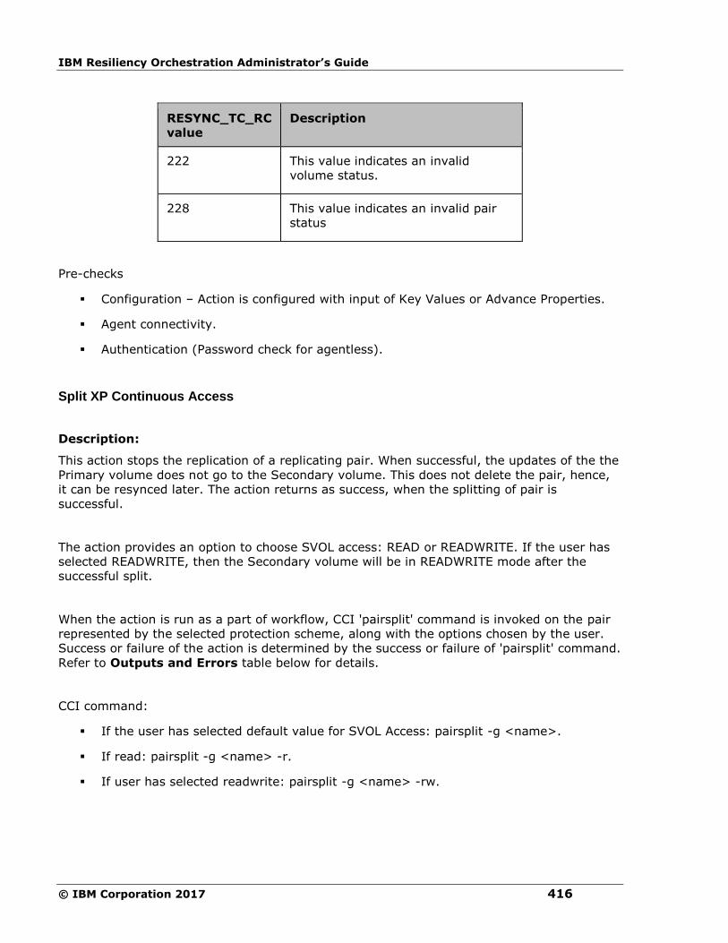
IBM Resiliency Orchestration Administrator’s Guide
© IBM Corporation 2017 416
RESYNC_TC_RC
value
Description
222 This value indicates an invalid
volume status.
228 This value indicates an invalid pair
status
Pre-checks
▪ Configuration – Action is configured with input of Key Values or Advance Properties.
▪ Agent connectivity.
▪ Authentication (Password check for agentless).
Split XP Continuous Access
Description:
This action stops the replication of a replicating pair. When successful, the updates of the the
Primary volume does not go to the Secondary volume. This does not delete the pair, hence,
it can be resynced later. The action returns as success, when the splitting of pair is
successful.
The action provides an option to choose SVOL access: READ or READWRITE. If the user has
selected READWRITE, then the Secondary volume will be in READWRITE mode after the
successful split.
When the action is run as a part of workflow, CCI 'pairsplit' command is invoked on the pair
represented by the selected protection scheme, along with the options chosen by the user.
Success or failure of the action is determined by the success or failure of 'pairsplit' command.
Refer to Outputs and Errors table below for details.
CCI command:
▪ If the user has selected default value for SVOL Access: pairsplit -g <name>.
▪ If read: pairsplit -g <name> -r.
▪ If user has selected readwrite: pairsplit -g <name> -rw.

Configuration
417
Inputs:
UI Input Input Key Name Description
Protection
Scheme
Name
SPLIT_TC_OPER_ON,
SPLIT_TC_OPER_ON_TYPE
Select the protection
scheme name configured
for the group from the
drop-down list.
Note:
If the group is attached
with more than one pair of
protection subsystem then
do not select "Current
Production Service" or
"Current DR Service".
Instead, select the actual
protection subsystem to
configure the operation.
SVOL
Access
SPLIT_TC_SVOL_ACCESS
Select an appropriate
option from the drop-down
list. The options are:
▪ READ
▪ READWRITE
Outputs and Errors:
The SPLIT_TC_RC key is set with an exit status of 'pairsplit' command.
Following are the possible values:
▪ A return code '0' indicates success.
▪ All other values indicates failure.
SPLIT_TC_RC
value Description
0 This value indicates that all the pairs in the group are
successfully suspended.
non zero This value indicates some failure in splitting of group.

IBM Resiliency Orchestration Administrator’s Guide
© IBM Corporation 2017 418
SPLIT_TC_RC
value
Description
236 This value indicates an unmatched volume status
within the group.
229 This value indicates an inconsistent status in group.
222 This value indicates an invalid volume status.
235 This value indicates a Pair Volume combination error.
228 This value indicates an invalid pair status
234 This value indicates a Pair suspended at WAIT state.
Pre-checks
▪ Configuration – Action is configured with input of Key Values or Advance Properties.
▪ Agent connectivity.
▪ Authentication (Password check for agentless).
Get Status
Description:
This action reports the volume status (whether paired or not, and if paired, whether it is SVol
or PVol) and pair status (HP XP specific pair status that indicates the current state of
replication).
When the action is run as a part of the workflow, CCI 'pairvolchk' command is invoked on the
volume represented by the selected protection scheme, along with the options chosen by the
user. Success or failure of the action is determined by the success or failure of 'pairvolchk'
command. Refer to Outputs and Errors table below for details.
CCI command: pairvolchk -g <name>.
Input:
UI Input Input Key Name Description
Protection
Scheme
Name
GET_TC_STATUS_OPER_ON,
GET_TC_STATUS_OPER_ON_TYPE
Select the protection scheme
name configured for the
group from the drop-down
list.
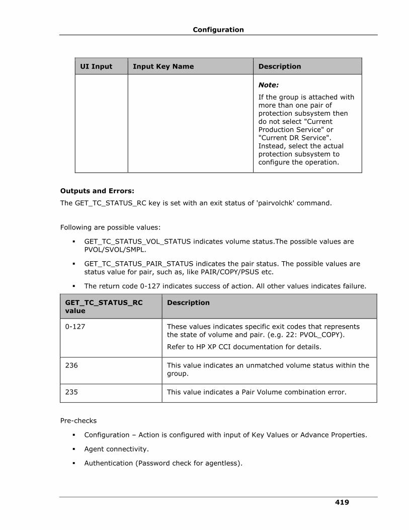
Configuration
419
UI Input Input Key Name Description
Note:
If the group is attached with
more than one pair of
protection subsystem then
do not select "Current
Production Service" or
"Current DR Service".
Instead, select the actual
protection subsystem to
configure the operation.
Outputs and Errors:
The GET_TC_STATUS_RC key is set with an exit status of 'pairvolchk' command.
Following are possible values:
▪ GET_TC_STATUS_VOL_STATUS indicates volume status.The possible values are
PVOL/SVOL/SMPL.
▪ GET_TC_STATUS_PAIR_STATUS indicates the pair status. The possible values are
status value for pair, such as, like PAIR/COPY/PSUS etc.
▪ The return code 0-127 indicates success of action. All other values indicates failure.
GET_TC_STATUS_RC
value
Description
0-127 These values indicates specific exit codes that represents
the state of volume and pair. (e.g. 22: PVOL_COPY).
Refer to HP XP CCI documentation for details.
236 This value indicates an unmatched volume status within the
group.
235 This value indicates a Pair Volume combination error.
Pre-checks
▪ Configuration – Action is configured with input of Key Values or Advance Properties.
▪ Agent connectivity.
▪ Authentication (Password check for agentless).
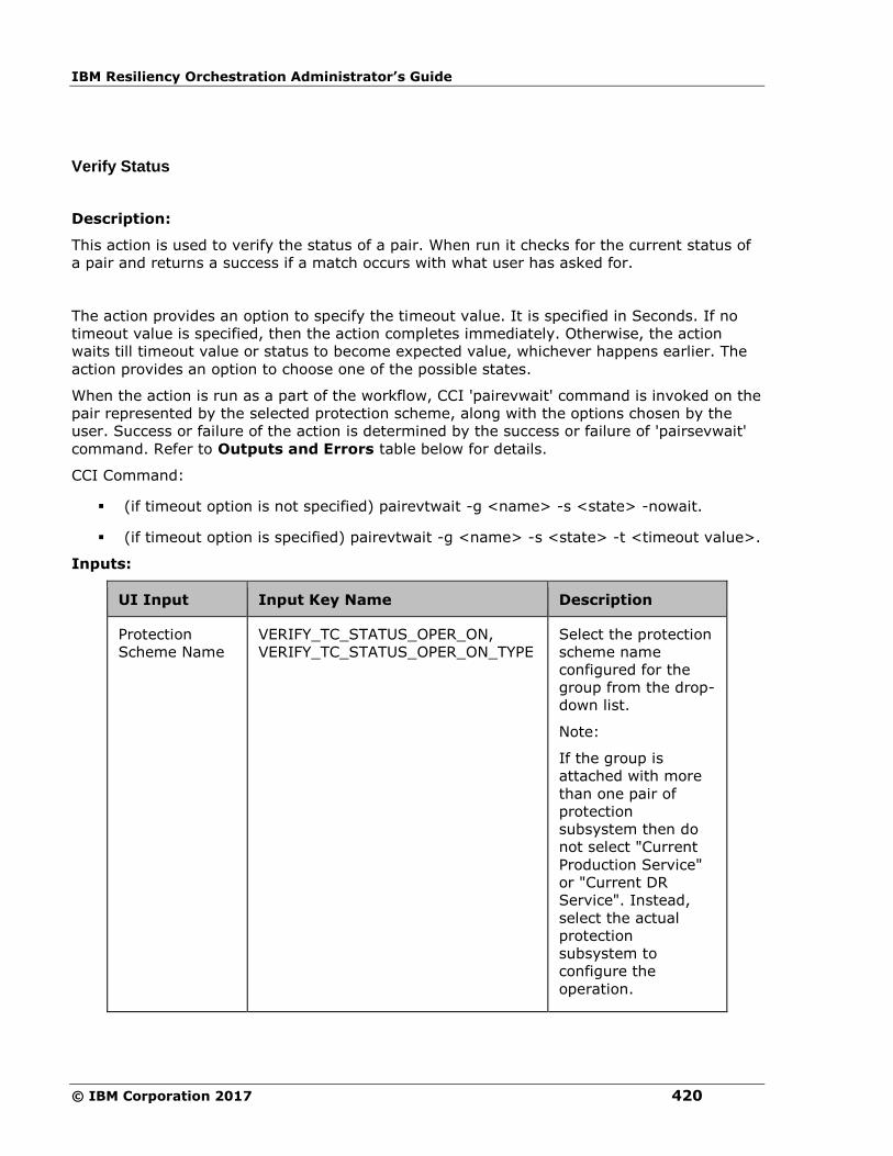
IBM Resiliency Orchestration Administrator’s Guide
© IBM Corporation 2017 420
Verify Status
Description:
This action is used to verify the status of a pair. When run it checks for the current status of
a pair and returns a success if a match occurs with what user has asked for.
The action provides an option to specify the timeout value. It is specified in Seconds. If no
timeout value is specified, then the action completes immediately. Otherwise, the action
waits till timeout value or status to become expected value, whichever happens earlier. The
action provides an option to choose one of the possible states.
When the action is run as a part of the workflow, CCI 'pairevwait' command is invoked on the
pair represented by the selected protection scheme, along with the options chosen by the
user. Success or failure of the action is determined by the success or failure of 'pairsevwait'
command. Refer to Outputs and Errors table below for details.
CCI Command:
▪ (if timeout option is not specified) pairevtwait -g <name> -s <state> -nowait.
▪ (if timeout option is specified) pairevtwait -g <name> -s <state> -t <timeout value>.
Inputs:
UI Input Input Key Name Description
Protection
Scheme Name
VERIFY_TC_STATUS_OPER_ON,
VERIFY_TC_STATUS_OPER_ON_TYPE
Select the protection
scheme name
configured for the
group from the drop-
down list.
Note:
If the group is
attached with more
than one pair of
protection
subsystem then do
not select "Current
Production Service"
or "Current DR
Service". Instead,
select the actual
protection
subsystem to
configure the
operation.
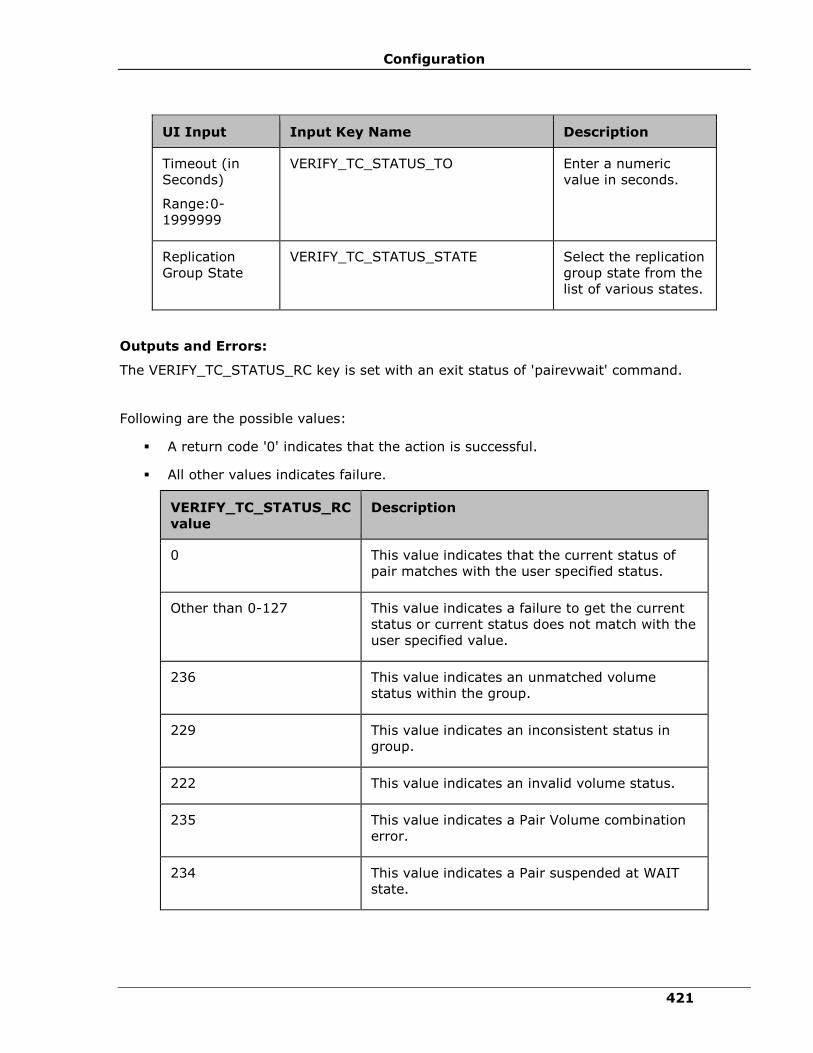
Configuration
421
UI Input Input Key Name Description
Timeout (in
Seconds)
Range:0-
1999999
VERIFY_TC_STATUS_TO Enter a numeric
value in seconds.
Replication
Group State
VERIFY_TC_STATUS_STATE Select the replication
group state from the
list of various states.
Outputs and Errors:
The VERIFY_TC_STATUS_RC key is set with an exit status of 'pairevwait' command.
Following are the possible values:
▪ A return code '0' indicates that the action is successful.
▪ All other values indicates failure.
VERIFY_TC_STATUS_RC
value
Description
0 This value indicates that the current status of
pair matches with the user specified status.
Other than 0-127 This value indicates a failure to get the current
status or current status does not match with the
user specified value.
236 This value indicates an unmatched volume
status within the group.
229 This value indicates an inconsistent status in
group.
222 This value indicates an invalid volume status.
235 This value indicates a Pair Volume combination
error.
234 This value indicates a Pair suspended at WAIT
state.
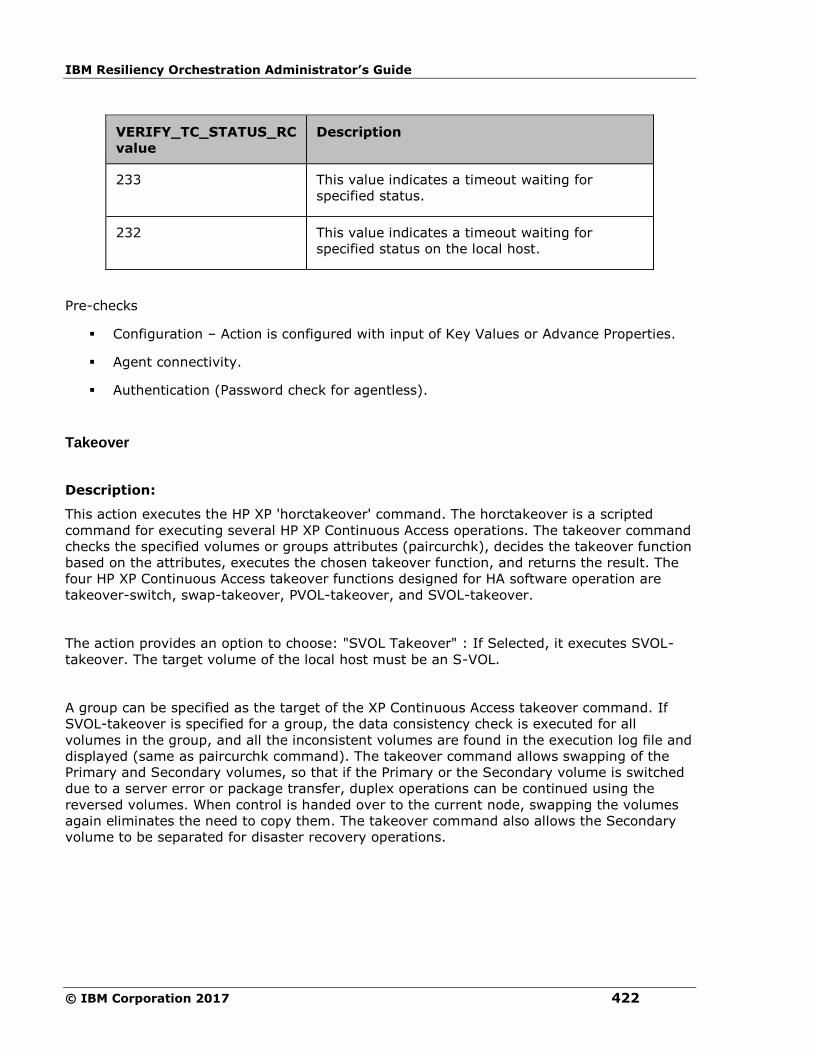
IBM Resiliency Orchestration Administrator’s Guide
© IBM Corporation 2017 422
VERIFY_TC_STATUS_RC
value
Description
233 This value indicates a timeout waiting for
specified status.
232 This value indicates a timeout waiting for
specified status on the local host.
Pre-checks
▪ Configuration – Action is configured with input of Key Values or Advance Properties.
▪ Agent connectivity.
▪ Authentication (Password check for agentless).
Takeover
Description:
This action executes the HP XP 'horctakeover' command. The horctakeover is a scripted
command for executing several HP XP Continuous Access operations. The takeover command
checks the specified volumes or groups attributes (paircurchk), decides the takeover function
based on the attributes, executes the chosen takeover function, and returns the result. The
four HP XP Continuous Access takeover functions designed for HA software operation are
takeover-switch, swap-takeover, PVOL-takeover, and SVOL-takeover.
The action provides an option to choose: "SVOL Takeover" : If Selected, it executes SVOL-
takeover. The target volume of the local host must be an S-VOL.
A group can be specified as the target of the XP Continuous Access takeover command. If
SVOL-takeover is specified for a group, the data consistency check is executed for all
volumes in the group, and all the inconsistent volumes are found in the execution log file and
displayed (same as paircurchk command). The takeover command allows swapping of the
Primary and Secondary volumes, so that if the Primary or the Secondary volume is switched
due to a server error or package transfer, duplex operations can be continued using the
reversed volumes. When control is handed over to the current node, swapping the volumes
again eliminates the need to copy them. The takeover command also allows the Secondary
volume to be separated for disaster recovery operations.
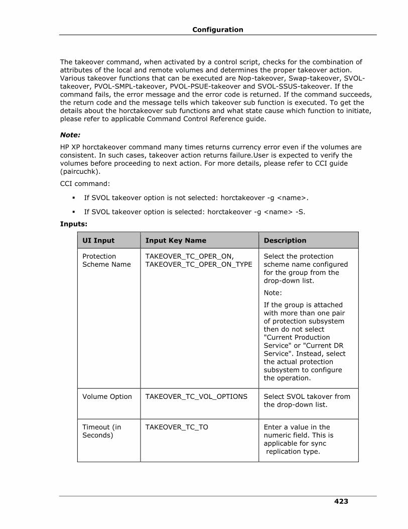
Configuration
423
The takeover command, when activated by a control script, checks for the combination of
attributes of the local and remote volumes and determines the proper takeover action.
Various takeover functions that can be executed are Nop-takeover, Swap-takeover, SVOL-
takeover, PVOL-SMPL-takeover, PVOL-PSUE-takeover and SVOL-SSUS-takeover. If the
command fails, the error message and the error code is returned. If the command succeeds,
the return code and the message tells which takeover sub function is executed. To get the
details about the horctakeover sub functions and what state cause which function to initiate,
please refer to applicable Command Control Reference guide.
Note:
HP XP horctakeover command many times returns currency error even if the volumes are
consistent. In such cases, takeover action returns failure.User is expected to verify the
volumes before proceeding to next action. For more details, please refer to CCI guide
(paircuchk).
CCI command:
▪ If SVOL takeover option is not selected: horctakeover -g <name>.
▪ If SVOL takeover option is selected: horctakeover -g <name> -S.
Inputs:
UI Input Input Key Name Description
Protection
Scheme Name
TAKEOVER_TC_OPER_ON,
TAKEOVER_TC_OPER_ON_TYPE
Select the protection
scheme name configured
for the group from the
drop-down list.
Note:
If the group is attached
with more than one pair
of protection subsystem
then do not select
"Current Production
Service" or "Current DR
Service". Instead, select
the actual protection
subsystem to configure
the operation.
Volume Option TAKEOVER_TC_VOL_OPTIONS
Select SVOL takover from
the drop-down list.
Timeout (in
Seconds)
TAKEOVER_TC_TO Enter a value in the
numeric field. This is
applicable for sync
replication type.
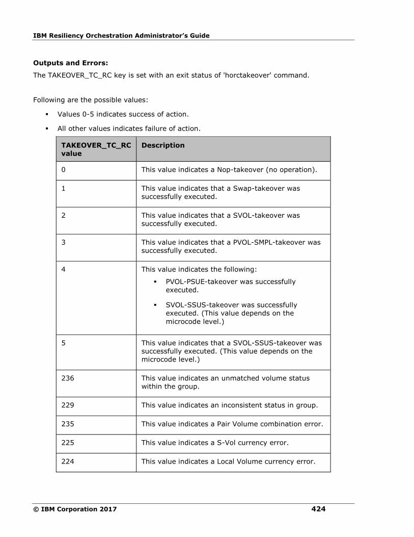
IBM Resiliency Orchestration Administrator’s Guide
© IBM Corporation 2017 424
Outputs and Errors:
The TAKEOVER_TC_RC key is set with an exit status of 'horctakeover' command.
Following are the possible values:
▪ Values 0-5 indicates success of action.
▪ All other values indicates failure of action.
TAKEOVER_TC_RC
value
Description
0 This value indicates a Nop-takeover (no operation).
1 This value indicates that a Swap-takeover was
successfully executed.
2 This value indicates that a SVOL-takeover was
successfully executed.
3 This value indicates that a PVOL-SMPL-takeover was
successfully executed.
4 This value indicates the following:
▪ PVOL-PSUE-takeover was successfully
executed.
▪ SVOL-SSUS-takeover was successfully
executed. (This value depends on the
microcode level.)
5 This value indicates that a SVOL-SSUS-takeover was
successfully executed. (This value depends on the
microcode level.)
236 This value indicates an unmatched volume status
within the group.
229 This value indicates an inconsistent status in group.
235 This value indicates a Pair Volume combination error.
225 This value indicates a S-Vol currency error.
224 This value indicates a Local Volume currency error.

Configuration
425
TAKEOVER_TC_RC
value
Description
223 This value indicates a Local and Remote Volume
currency error.
233 This value indicates a timeout waiting for specified
status.
Pre-checks
▪ Configuration – Action is configured with input of Key Values or Advance Properties.
▪ Agent connectivity.
▪ Authentication (Password check for agentless).
Delete XP Continuous Access
Description:
This action deletes the replication relationship between the Primary volume and the
Secondary volume. The user cannot resync the delta changes between the Primary and the
Secondary volume, once it is deleted.
The action provides an option to choose "Force" : If selected, it brings the Secondary volume
into the simplex mode forcibly. It is issued by the secondary host, if the host possessing the
Primary volume is down or has failed.
When the action is run as a part of the workflow, CCI 'pairsplit -S' command is invoked on
the pair represented by the selected protection scheme, along with the options chosen by the
user. Success or failure of the action is determined by the success or failure of 'pairsplit'
command. Refer to Outputs and Errors table below for details.
CCI Command:
▪ if force option is not selected: pairsplit -g <name> -S.
▪ if force option is selected: pairsplit -g <name> -S –R.
Inputs:
UI Input Input Key Name Description
Protection
Scheme Name
DELETE_TC_OPER_ON,
DELETE_TC_OPER_ON_TYPE
Select the protection
scheme name configured
for the group from the
drop-down list.
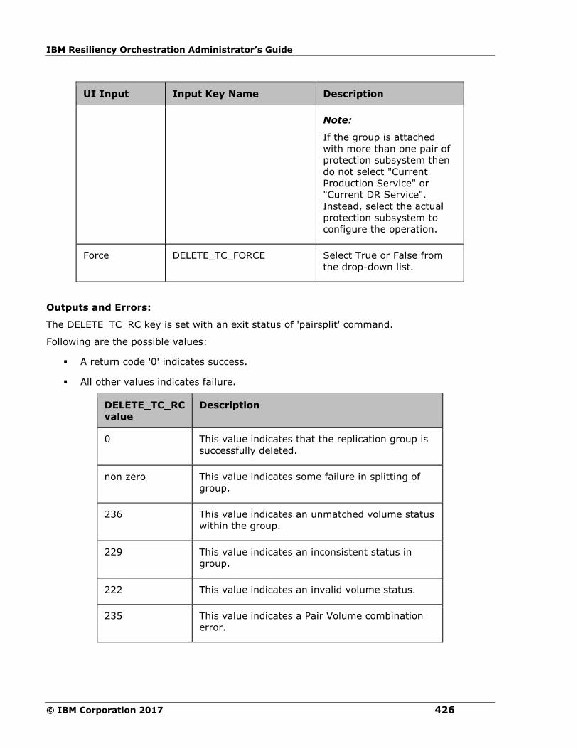
IBM Resiliency Orchestration Administrator’s Guide
© IBM Corporation 2017 426
UI Input Input Key Name Description
Note:
If the group is attached
with more than one pair of
protection subsystem then
do not select "Current
Production Service" or
"Current DR Service".
Instead, select the actual
protection subsystem to
configure the operation.
Force DELETE_TC_FORCE Select True or False from
the drop-down list.
Outputs and Errors:
The DELETE_TC_RC key is set with an exit status of 'pairsplit' command.
Following are the possible values:
▪ A return code '0' indicates success.
▪ All other values indicates failure.
DELETE_TC_RC
value
Description
0 This value indicates that the replication group is
successfully deleted.
non zero This value indicates some failure in splitting of
group.
236 This value indicates an unmatched volume status
within the group.
229 This value indicates an inconsistent status in
group.
222 This value indicates an invalid volume status.
235 This value indicates a Pair Volume combination
error.
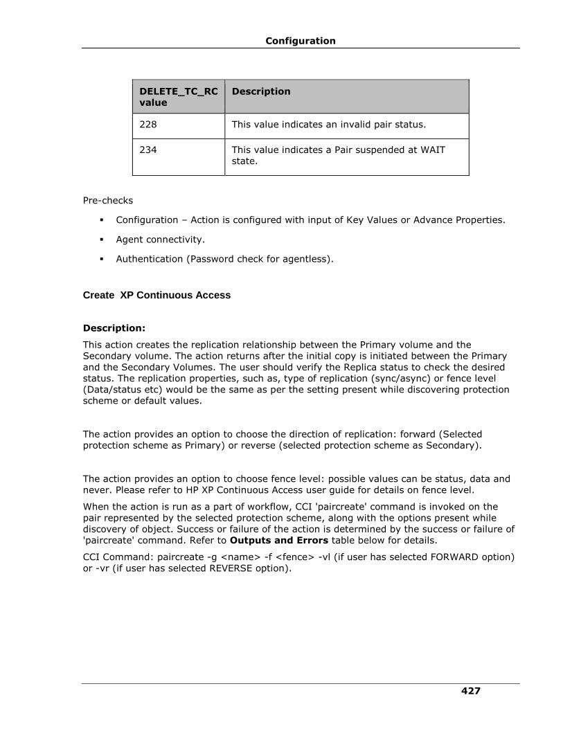
Configuration
427
DELETE_TC_RC
value
Description
228 This value indicates an invalid pair status.
234 This value indicates a Pair suspended at WAIT
state.
Pre-checks
▪ Configuration – Action is configured with input of Key Values or Advance Properties.
▪ Agent connectivity.
▪ Authentication (Password check for agentless).
Create XP Continuous Access
Description:
This action creates the replication relationship between the Primary volume and the
Secondary volume. The action returns after the initial copy is initiated between the Primary
and the Secondary Volumes. The user should verify the Replica status to check the desired
status. The replication properties, such as, type of replication (sync/async) or fence level
(Data/status etc) would be the same as per the setting present while discovering protection
scheme or default values.
The action provides an option to choose the direction of replication: forward (Selected
protection scheme as Primary) or reverse (selected protection scheme as Secondary).
The action provides an option to choose fence level: possible values can be status, data and
never. Please refer to HP XP Continuous Access user guide for details on fence level.
When the action is run as a part of workflow, CCI 'paircreate' command is invoked on the
pair represented by the selected protection scheme, along with the options present while
discovery of object. Success or failure of the action is determined by the success or failure of
'paircreate' command. Refer to Outputs and Errors table below for details.
CCI Command: paircreate -g <name> -f <fence> -vl (if user has selected FORWARD option)
or -vr (if user has selected REVERSE option).
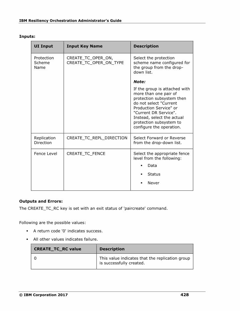
IBM Resiliency Orchestration Administrator’s Guide
© IBM Corporation 2017 428
Inputs:
UI Input Input Key Name Description
Protection
Scheme
Name
CREATE_TC_OPER_ON,
CREATE_TC_OPER_ON_TYPE
Select the protection
scheme name configured for
the group from the drop-
down list.
Note:
If the group is attached with
more than one pair of
protection subsystem then
do not select "Current
Production Service" or
"Current DR Service".
Instead, select the actual
protection subsystem to
configure the operation.
Replication
Direction
CREATE_TC_REPL_DIRECTION Select Forward or Reverse
from the drop-down list.
Fence Level CREATE_TC_FENCE Select the appropriate fence
level from the following:
▪ Data
▪ Status
▪ Never
Outputs and Errors:
The CREATE_TC_RC key is set with an exit status of 'paircreate' command.
Following are the possible values:
▪ A return code '0' indicates success.
▪ All other values indicates failure.
CREATE_TC_RC value Description
0 This value indicates that the replication group
is successfully created.

Configuration
429
CREATE_TC_RC value Description
non zero This value indicates some failure in creation
of replication group.
236 This value indicates an unmatched volume
status within the group.
229 This value indicates an inconsistent status in
group.
222 This value indicates an invalid volume status.
228 This value indicates an invalid pair status.
212 This value indicates a Pair suspended at
WAIT state.
Pre-checks
▪ Configuration – Action is configured with input of Key Values or Advance Properties.
▪ Agent connectivity.
▪ Authentication (Password check for agentless).
Role Switch
Description:
This action re-establishes a split pair in the reverse direction. The Primary volume becomes
the Secondary volume and vice versa. If it is successful, all the changes done on the
Secondary starts getting updated on the Primary volume. The action completes after
reversing the role and initiating the reverse resync request. It does not wait for
resynchronization to complete. The 'Check Status' or 'Verify Status' action should be used to
check if the pair has arrived to a particular state.
When the action is run as a part of the workflow, CCI 'pairresync -swapp or -swaps'
command is invoked on the pair represented by the selected protection scheme, along with
the options chosen by the user. Success or failure of the action is determined by the success
or failure of 'pairresync' command. Refer to Outputs and Errors table below for details.
CCI Command: pairvolchk -g <name> and pairresync -g <name> -swapp.
Input:
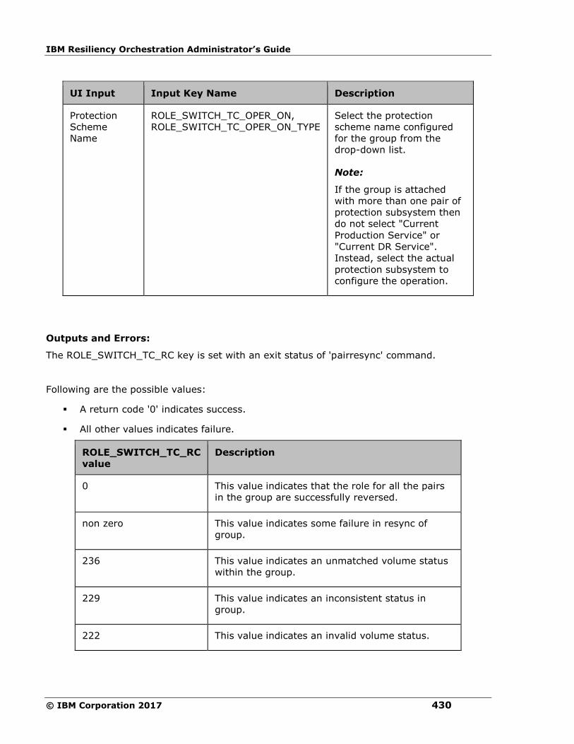
IBM Resiliency Orchestration Administrator’s Guide
© IBM Corporation 2017 430
UI Input Input Key Name Description
Protection
Scheme
Name
ROLE_SWITCH_TC_OPER_ON,
ROLE_SWITCH_TC_OPER_ON_TYPE
Select the protection
scheme name configured
for the group from the
drop-down list.
Note:
If the group is attached
with more than one pair of
protection subsystem then
do not select "Current
Production Service" or
"Current DR Service".
Instead, select the actual
protection subsystem to
configure the operation.
Outputs and Errors:
The ROLE_SWITCH_TC_RC key is set with an exit status of 'pairresync' command.
Following are the possible values:
▪ A return code '0' indicates success.
▪ All other values indicates failure.
ROLE_SWITCH_TC_RC
value
Description
0 This value indicates that the role for all the pairs
in the group are successfully reversed.
non zero This value indicates some failure in resync of
group.
236 This value indicates an unmatched volume status
within the group.
229 This value indicates an inconsistent status in
group.
222 This value indicates an invalid volume status.

Configuration
431
ROLE_SWITCH_TC_RC
value
Description
228 This value indicates an invalid pair status.
Pre-checks
▪ Configuration – Action is configured with input of Key Values or Advance Properties.
▪ Agent connectivity.
▪ Authentication (Password check for agentless).
Check Consistency
Description:
This action checks for the consistency of the Secondary volume.The action call HP XP CCI
'paircurchk' command, which checks for the currency of the HP XP Continuous Access
Secondary volume(s), by evaluating the data consistency based on pair status and fence
level. The action fails if the Secondary volume is not consistent. Please refer to HP XP CCI
reference manual to know about the data consistency for each possible states of a HP XP
Continuous Access volume.
When the action is run as a part of the workflow, CCI 'paircurchk' command is invoked on the
pair represented by the selected protection scheme, along with the options chosen by the
user. The action returns success if the data volumes are consistent. In all other cases, it fails.
Refer to Outputs and Errors table below to for details.
Note
HP XP paircurchk command many times returns currency error even if the volumes are
consistent. In such cases, consistency check action returns failure. For more details, please
refer to CCI guide (paircuchk).
CCI Command: paircurchk -g <name>.
Inputs:
UI Input Input Key Name Description
Protection
Scheme
Name
CHECK_CONSISTENCY_TC_OPER_ON,
CHECK_CONSISTENCY_TC_OPER_ON_TYPE
Select the
protection scheme
name configured
for the group from
the drop-down list.
Note:
If the group is
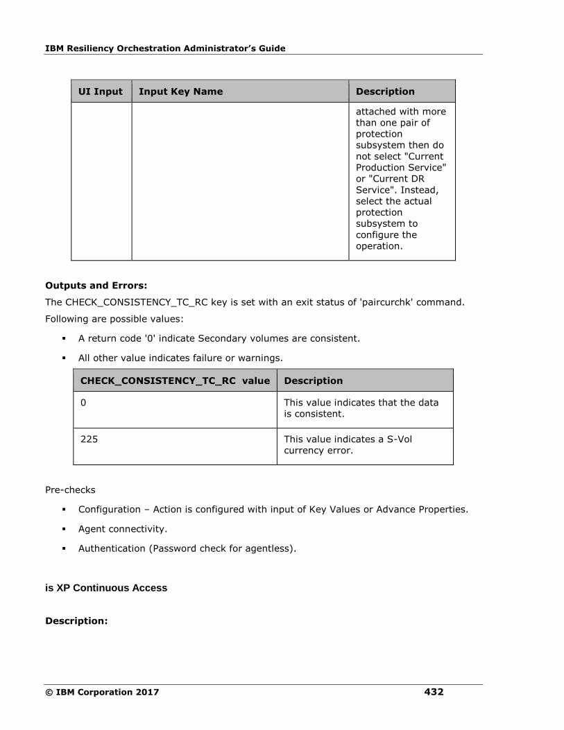
IBM Resiliency Orchestration Administrator’s Guide
© IBM Corporation 2017 432
UI Input Input Key Name Description
attached with more
than one pair of
protection
subsystem then do
not select "Current
Production Service"
or "Current DR
Service". Instead,
select the actual
protection
subsystem to
configure the
operation.
Outputs and Errors:
The CHECK_CONSISTENCY_TC_RC key is set with an exit status of 'paircurchk' command.
Following are possible values:
▪ A return code '0' indicate Secondary volumes are consistent.
▪ All other value indicates failure or warnings.
CHECK_CONSISTENCY_TC_RC value Description
0 This value indicates that the data
is consistent.
225 This value indicates a S-Vol
currency error.
Pre-checks
▪ Configuration – Action is configured with input of Key Values or Advance Properties.
▪ Agent connectivity.
▪ Authentication (Password check for agentless).
is XP Continuous Access
Description:
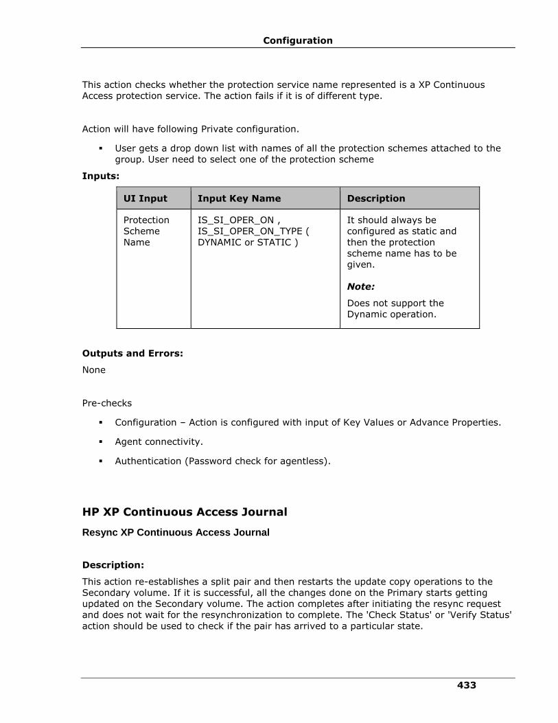
Configuration
433
This action checks whether the protection service name represented is a XP Continuous
Access protection service. The action fails if it is of different type.
Action will have following Private configuration.
▪ User gets a drop down list with names of all the protection schemes attached to the
group. User need to select one of the protection scheme
Inputs:
UI Input Input Key Name Description
Protection
Scheme
Name
IS_SI_OPER_ON ,
IS_SI_OPER_ON_TYPE (
DYNAMIC or STATIC )
It should always be
configured as static and
then the protection
scheme name has to be
given.
Note:
Does not support the
Dynamic operation.
Outputs and Errors:
None
Pre-checks
▪ Configuration – Action is configured with input of Key Values or Advance Properties.
▪ Agent connectivity.
▪ Authentication (Password check for agentless).
HP XP Continuous Access Journal
Resync XP Continuous Access Journal
Description:
This action re-establishes a split pair and then restarts the update copy operations to the
Secondary volume. If it is successful, all the changes done on the Primary starts getting
updated on the Secondary volume. The action completes after initiating the resync request
and does not wait for the resynchronization to complete. The 'Check Status' or 'Verify Status'
action should be used to check if the pair has arrived to a particular state.
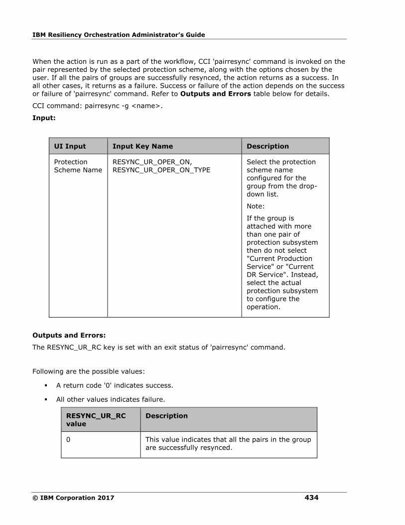
IBM Resiliency Orchestration Administrator’s Guide
© IBM Corporation 2017 434
When the action is run as a part of the workflow, CCI 'pairresync' command is invoked on the
pair represented by the selected protection scheme, along with the options chosen by the
user. If all the pairs of groups are successfully resynced, the action returns as a success. In
all other cases, it returns as a failure. Success or failure of the action depends on the success
or failure of 'pairresync' command. Refer to Outputs and Errors table below for details.
CCI command: pairresync -g <name>.
Input:
UI Input Input Key Name Description
Protection
Scheme Name
RESYNC_UR_OPER_ON,
RESYNC_UR_OPER_ON_TYPE
Select the protection
scheme name
configured for the
group from the drop-
down list.
Note:
If the group is
attached with more
than one pair of
protection subsystem
then do not select
"Current Production
Service" or "Current
DR Service". Instead,
select the actual
protection subsystem
to configure the
operation.
Outputs and Errors:
The RESYNC_UR_RC key is set with an exit status of 'pairresync' command.
Following are the possible values:
▪ A return code '0' indicates success.
▪ All other values indicates failure.
RESYNC_UR_RC
value
Description
0 This value indicates that all the pairs in the group
are successfully resynced.

Configuration
435
RESYNC_UR_RC
value
Description
non zero This value indicates some failure in resync of
group.
236 This value indicates an unmatched volume status
within the group.
229 This value indicates an inconsistent status in
group.
222 This value indicates an invalid volume status.
228 This value indicates an invalid pair status.
Pre-checks
▪ Configuration – Action is configured with input of Key Values or Advance Properties.
▪ Agent connectivity.
▪ Authentication (Password check for agentless).
Split XP Continuous Access Journal
Description:
This action stops the replication of a replicating pair. When successful, the updates of the
Primary volume do not go to the Secondary volume. This does not delete the pair, hence, it
can be resynced later. The action returns a success when splitting of pair is successful.
The action provides an option to choose SVOL access: READ or READWRITE. If the user has
selected READWRITE, then the Secondary volume will be in READWRITE mode after the
successful split.
When the action is run as a part of the workflow, CCI 'pairsplit' command is invoked on the
pair represented by the selected protection scheme, along with the options chosen by the
user. Success or failure of the action is determined by the success or failure of 'pairsplit'
command. Refer to Outputs and Errors table below for details.
CCI command:
▪ If the user has selected default value for SVOL Access: pairsplit -g <name>.
▪ If read: pairsplit -g <name> -r.

IBM Resiliency Orchestration Administrator’s Guide
© IBM Corporation 2017 436
▪ If user has selected readwrite: pairsplit -g <name> -rw.
Inputs:
UI Input Input Key Name Description
Protection
Scheme Name
SPLIT_UR_OPER_ON,
SPLIT_UR_OPER_ON_TYPE
Select the protection scheme name
configured for the group from the
drop-down list.
Note:
If the group is attached with more than
one pair of protection subsystem then
do not select "Current Production
Service" or "Current DR Service".
Instead, select the actual protection
subsystem to configure the operation.
SVOL Access SPLIT_UR_SVOL_ACCESS Select an appropriate option from the
drop-down list. The options are:
▪ READ
▪ READWRITE
Outputs and Errors:
The SPLIT_UR_RC key is set with an exit status of 'pairsplit' command.
Following are the possible values:
▪ A return code '0' indicates success.
▪ All other values indicates failure.
SPLIT_UR_RC value Description
0 This value indicates that all the
pairs in the group are
successfully suspended.
non zero This value indicates some failure
in splitting of group.
236 This value indicates an
unmatched volume status within
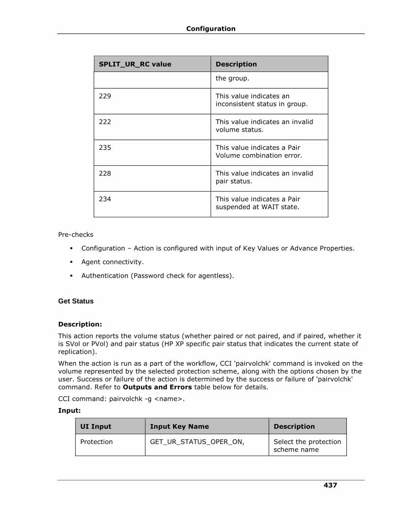
Configuration
437
SPLIT_UR_RC value Description
the group.
229 This value indicates an
inconsistent status in group.
222 This value indicates an invalid
volume status.
235 This value indicates a Pair
Volume combination error.
228 This value indicates an invalid
pair status.
234 This value indicates a Pair
suspended at WAIT state.
Pre-checks
▪ Configuration – Action is configured with input of Key Values or Advance Properties.
▪ Agent connectivity.
▪ Authentication (Password check for agentless).
Get Status
Description:
This action reports the volume status (whether paired or not paired, and if paired, whether it
is SVol or PVol) and pair status (HP XP specific pair status that indicates the current state of
replication).
When the action is run as a part of the workflow, CCI 'pairvolchk' command is invoked on the
volume represented by the selected protection scheme, along with the options chosen by the
user. Success or failure of the action is determined by the success or failure of 'pairvolchk'
command. Refer to Outputs and Errors table below for details.
CCI command: pairvolchk -g <name>.
Input:
UI Input Input Key Name Description
Protection GET_UR_STATUS_OPER_ON, Select the protection
scheme name

IBM Resiliency Orchestration Administrator’s Guide
© IBM Corporation 2017 438
UI Input Input Key Name Description
Scheme Name GET_UR_STATUS_OPER_ON_TYPE configured for the
group from the
drop-down list.
Note:
If the group is
attached with more
than one pair of
protection
subsystem then do
not select "Current
Production Service"
or "Current DR
Service". Instead,
select the actual
protection
subsystem to
configure the
operation.
Outputs and Errors:
The GET_UR_STATUS_RC key is set with an exit status of 'pairvolchk' command.
Following are possible values:
▪ GET_UR_STATUS_VOL_STATUS indicates volume status. Possible values are
PVOL/SVOL/SMPL.
▪ GET_UR_STATUS_PAIR_STATUS indicates pair status. possible values are status value
for pair like PAIR/COPY/PSUS etc.
▪ Return code 0-127 indicate success of action. All other value indicates failure.
GET_UR_STATUS_RC value Description
0-127 These values indicates specific exit codes
that represents the state of volume and
pair. (e.g. 22: PVOL_COPY).
Refer to HP XP CCI documentation for
details.
236 This value indicates an unmatched
volume status within the group.

Configuration
439
GET_UR_STATUS_RC value Description
235 This value indicates a Pair Volume
combination error.
Pre-checks
▪ Configuration – Action is configured with input of Key Values or Advance Properties.
▪ Agent connectivity.
▪ Authentication (Password check for agentless).
Verify Status
Description:
This action is used to verify the status of a pair. When run it checks the current status of a
pair and returns a success, if it matches with what user has asked for. If the user has
specified an optional timeout value, then the action periodically checks the status till either
the status of the pair becomes the expected value or the timeout expires. The action is
successful if the status of pair is what the user has asked for. In all other cases, the action
fails.
The action provides an option to specify the timeout value. It is specified in Seconds. If no
timeout value is specified, then the action completes immediately. Otherwise, the action
waits till timeout value or status to become expected value, whichever happens earlier. The
action provides an option to choose one of the possible states.
When the action is run as a part of workflow, CCI 'pairevwait' command is invoked on the
pair represented by the selected protection scheme, along with the options chosen by the
user. Success or failure of the action is determined by the success or failure of 'pairsevwait'
command. Refer to Outputs and Errors table below for details.
CCI Command:
▪ (if timeout option is not specified) pairevtwait -g <name> -s <state> -nowait.
▪ (if timeout option is specified) pairevtwait -g <name> -s <state> -t <timeout value>.
Inputs:
UI Input Input Key Name Description
Protection
Scheme
Name
VERIFY_UR_STATUS_OPER_ON,
VERIFY_UR_STATUS_OPER_ON_TYPE
Select the
protection
scheme name
configured for

IBM Resiliency Orchestration Administrator’s Guide
© IBM Corporation 2017 440
UI Input Input Key Name Description
the group from
the drop-down
list.
Note:
If the group is
attached with
more than one
pair of protection
subsystem then
do not select
"Current
Production
Service" or
"Current DR
Service".
Instead, select
the actual
protection
subsystem to
configure the
operation.
Timeout (in
Seconds)
Range:0-
1999999
VERIFY_UR_STATUS_TO Enter a numeric
value in seconds.
Replication
Group State
VERIFY_UR_STATUS_STATE Select the
replication group
state from the
list of various
states.
Outputs and Errors:
The VERIFY_UR_STATUS_RC key is set with an exit status of 'pairevwait' command.
Following are the possible values:
▪ A return code '0' indicates that the action is successful.
▪ All other values indicates failure.
VERIFY_UR_STATUS_RC
value
Description

Configuration
441
VERIFY_UR_STATUS_RC
value
Description
0 This value indicates that the current
status of pair matches with the user
specified status.
Other than 0-127 This value indicates a failure to get
the current status or current status
does not match with the user
specified value.
236 This value indicates an unmatched
volume status within the group.
229 This value indicates an inconsistent
status in group.
222 This value indicates an invalid
volume status.
235 This value indicates a Pair Volume
combination error.
234 This value indicates a Pair suspended
at WAIT state.
233 This value indicates a timeout waiting
for specified status.
232 This value indicates a timeout waiting
for specified status on the local host.
Pre-checks
▪ Configuration – Action is configured with input of Key Values or Advance Properties.
▪ Agent connectivity.
▪ Authentication (Password check for agentless).
Takeover
Description:
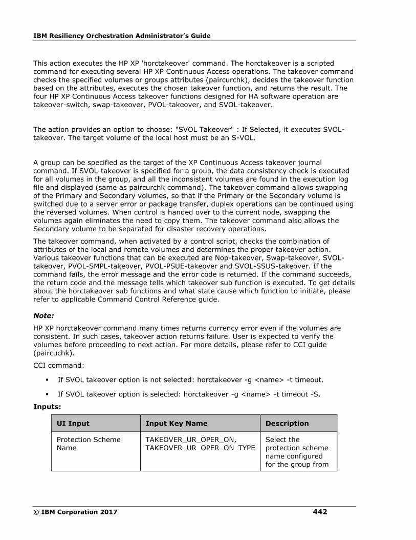
IBM Resiliency Orchestration Administrator’s Guide
© IBM Corporation 2017 442
This action executes the HP XP 'horctakeover' command. The horctakeover is a scripted
command for executing several HP XP Continuous Access operations. The takeover command
checks the specified volumes or groups attributes (paircurchk), decides the takeover function
based on the attributes, executes the chosen takeover function, and returns the result. The
four HP XP Continuous Access takeover functions designed for HA software operation are
takeover-switch, swap-takeover, PVOL-takeover, and SVOL-takeover.
The action provides an option to choose: "SVOL Takeover" : If Selected, it executes SVOL-
takeover. The target volume of the local host must be an S-VOL.
A group can be specified as the target of the XP Continuous Access takeover journal
command. If SVOL-takeover is specified for a group, the data consistency check is executed
for all volumes in the group, and all the inconsistent volumes are found in the execution log
file and displayed (same as paircurchk command). The takeover command allows swapping
of the Primary and Secondary volumes, so that if the Primary or the Secondary volume is
switched due to a server error or package transfer, duplex operations can be continued using
the reversed volumes. When control is handed over to the current node, swapping the
volumes again eliminates the need to copy them. The takeover command also allows the
Secondary volume to be separated for disaster recovery operations.
The takeover command, when activated by a control script, checks the combination of
attributes of the local and remote volumes and determines the proper takeover action.
Various takeover functions that can be executed are Nop-takeover, Swap-takeover, SVOL-
takeover, PVOL-SMPL-takeover, PVOL-PSUE-takeover and SVOL-SSUS-takeover. If the
command fails, the error message and the error code is returned. If the command succeeds,
the return code and the message tells which takeover sub function is executed. To get details
about the horctakeover sub functions and what state cause which function to initiate, please
refer to applicable Command Control Reference guide.
Note:
HP XP horctakeover command many times returns currency error even if the volumes are
consistent. In such cases, takeover action returns failure. User is expected to verify the
volumes before proceeding to next action. For more details, please refer to CCI guide
(paircuchk).
CCI command:
▪ If SVOL takeover option is not selected: horctakeover -g <name> -t timeout.
▪ If SVOL takeover option is selected: horctakeover -g <name> -t timeout -S.
Inputs:
UI Input Input Key Name Description
Protection Scheme
Name
TAKEOVER_UR_OPER_ON,
TAKEOVER_UR_OPER_ON_TYPE
Select the
protection scheme
name configured
for the group from

Configuration
443
UI Input Input Key Name Description
the drop-down list.
Note:
If the group is
attached with
more than one pair
of protection
subsystem then do
not select "Current
Production
Service" or
"Current DR
Service". Instead,
select the actual
protection
subsystem to
configure the
operation.
Volume Option TAKEOVER_UR_VOL_OPTIONS Select SVOL
takover from the
drop-down list.
Timeout (in Seconds) TAKEOVER_UR_TO Enter a value in
the numeric field.
Outputs and Errors:
The REPL_TAKEOVER_RC key is set with an exit status of 'horctakeover' command.
Following are the possible values:
▪ Values 0-5 indicates success of action.
▪ All other values indicates failure of action.
REPL_TAKEOVER_RC
value
Description
0 This value indicates a Nop-takeover (no
operation).
1 This value indicates that a Swap-takeover was
successfully executed.
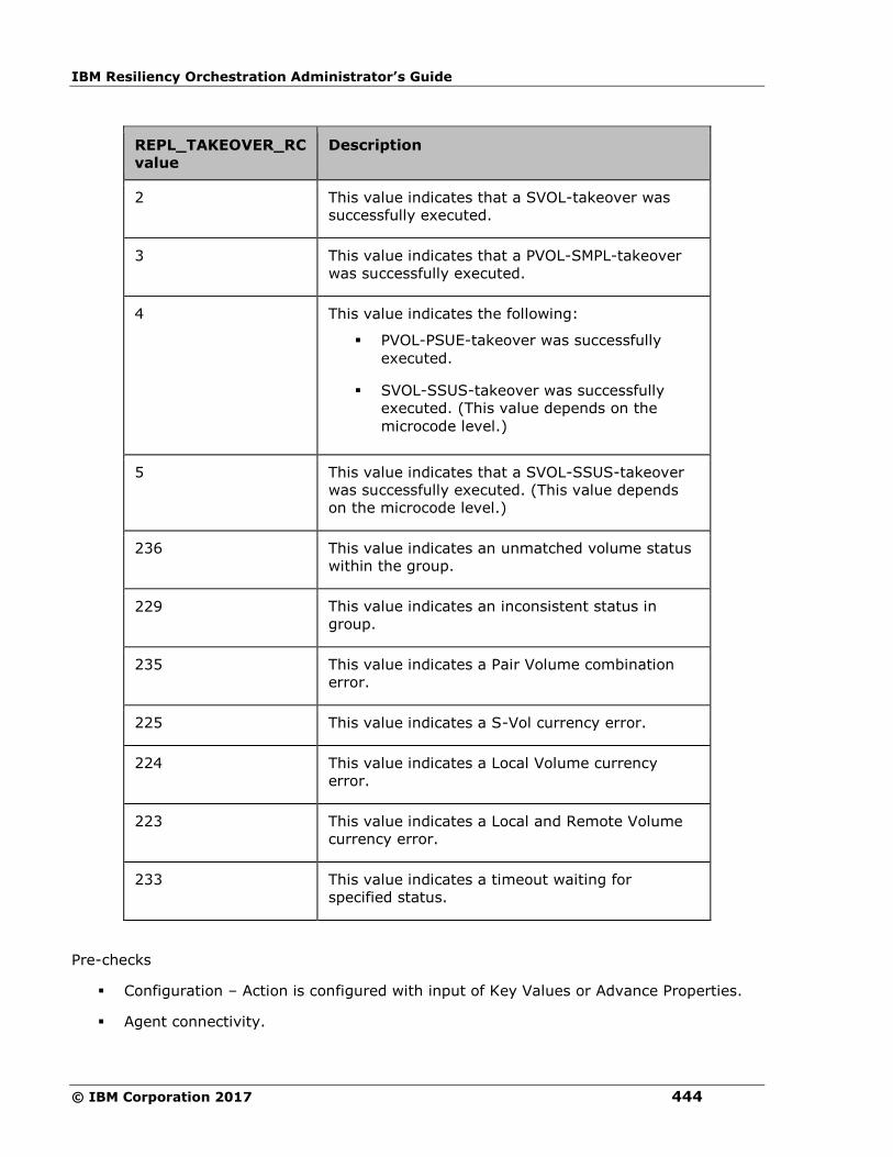
IBM Resiliency Orchestration Administrator’s Guide
© IBM Corporation 2017 444
REPL_TAKEOVER_RC
value
Description
2 This value indicates that a SVOL-takeover was
successfully executed.
3 This value indicates that a PVOL-SMPL-takeover
was successfully executed.
4 This value indicates the following:
▪ PVOL-PSUE-takeover was successfully
executed.
▪ SVOL-SSUS-takeover was successfully
executed. (This value depends on the
microcode level.)
5 This value indicates that a SVOL-SSUS-takeover
was successfully executed. (This value depends
on the microcode level.)
236 This value indicates an unmatched volume status
within the group.
229 This value indicates an inconsistent status in
group.
235 This value indicates a Pair Volume combination
error.
225 This value indicates a S-Vol currency error.
224 This value indicates a Local Volume currency
error.
223 This value indicates a Local and Remote Volume
currency error.
233 This value indicates a timeout waiting for
specified status.
Pre-checks
▪ Configuration – Action is configured with input of Key Values or Advance Properties.
▪ Agent connectivity.
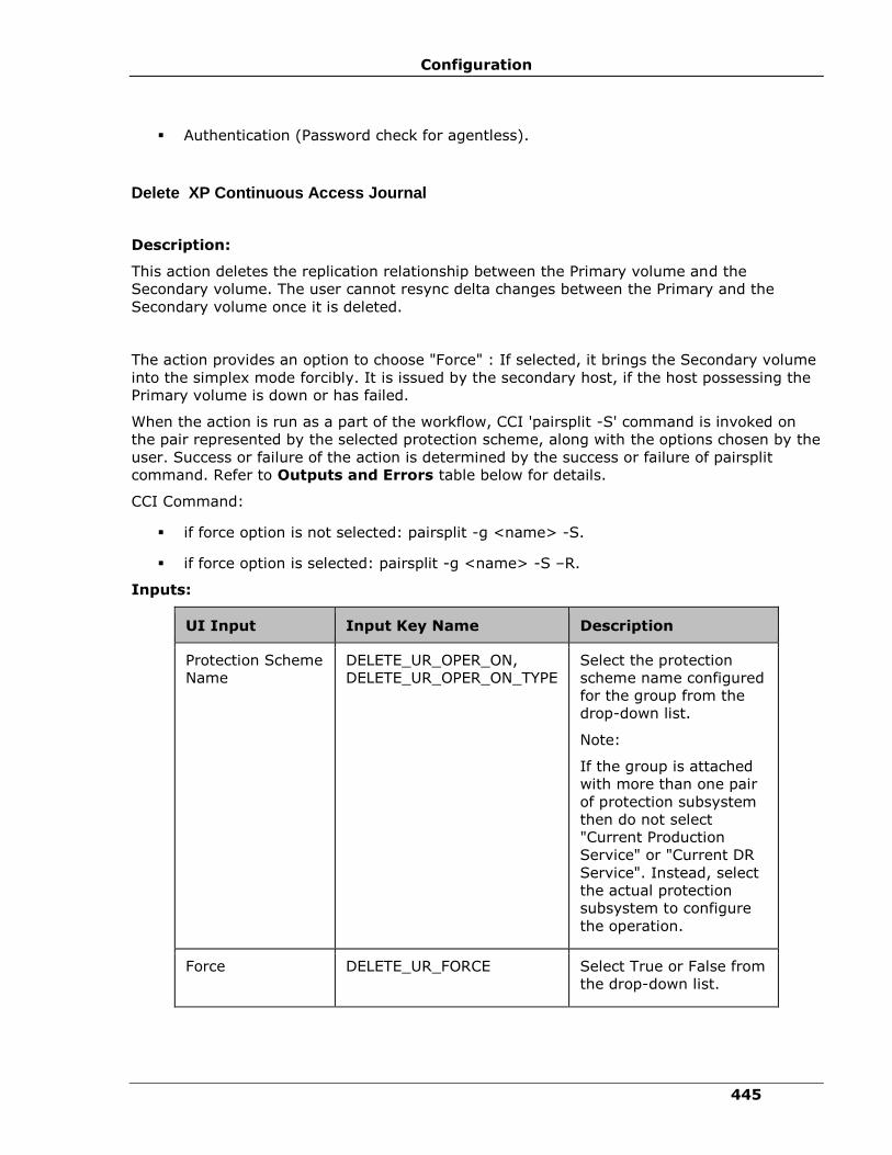
Configuration
445
▪ Authentication (Password check for agentless).
Delete XP Continuous Access Journal
Description:
This action deletes the replication relationship between the Primary volume and the
Secondary volume. The user cannot resync delta changes between the Primary and the
Secondary volume once it is deleted.
The action provides an option to choose "Force" : If selected, it brings the Secondary volume
into the simplex mode forcibly. It is issued by the secondary host, if the host possessing the
Primary volume is down or has failed.
When the action is run as a part of the workflow, CCI 'pairsplit -S' command is invoked on
the pair represented by the selected protection scheme, along with the options chosen by the
user. Success or failure of the action is determined by the success or failure of pairsplit
command. Refer to Outputs and Errors table below for details.
CCI Command:
▪ if force option is not selected: pairsplit -g <name> -S.
▪ if force option is selected: pairsplit -g <name> -S –R.
Inputs:
UI Input Input Key Name Description
Protection Scheme
Name
DELETE_UR_OPER_ON,
DELETE_UR_OPER_ON_TYPE
Select the protection
scheme name configured
for the group from the
drop-down list.
Note:
If the group is attached
with more than one pair
of protection subsystem
then do not select
"Current Production
Service" or "Current DR
Service". Instead, select
the actual protection
subsystem to configure
the operation.
Force DELETE_UR_FORCE Select True or False from
the drop-down list.
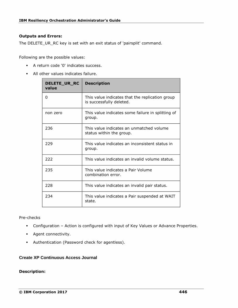
IBM Resiliency Orchestration Administrator’s Guide
© IBM Corporation 2017 446
Outputs and Errors:
The DELETE_UR_RC key is set with an exit status of 'pairsplit' command.
Following are the possible values:
▪ A return code '0' indicates success.
▪ All other values indicates failure.
DELETE_UR_RC
value
Description
0 This value indicates that the replication group
is successfully deleted.
non zero This value indicates some failure in splitting of
group.
236 This value indicates an unmatched volume
status within the group.
229 This value indicates an inconsistent status in
group.
222 This value indicates an invalid volume status.
235 This value indicates a Pair Volume
combination error.
228 This value indicates an invalid pair status.
234 This value indicates a Pair suspended at WAIT
state.
Pre-checks
▪ Configuration – Action is configured with input of Key Values or Advance Properties.
▪ Agent connectivity.
▪ Authentication (Password check for agentless).
Create XP Continuous Access Journal
Description:

Configuration
447
This action creates the replication relationship between the Primary volume and the
Secondary volume. The action returns after the initial copy is initiated between the Primary
and the Secondary Volumes. The user should verify the Replica status to check the desired
status. The replication properties, such as, type of replication (sync/async) or fence level
(Data/status etc) would be the same as per the setting present while discovering protection
scheme or default values.
The action provides an option to choose the direction of replication: forward (Selected
protection scheme as Primary) or reverse (selected protection scheme as Secondary).
The action provides an option to choose Journal ID for Primary volume and Secondary
volume. This ID refers to the journal group which will be used for asynchronous data transfer
for data volumes.
The action provides an option to specify the consistency group number: The concept of XP
Continuous Access Journal consistency group number equals to Continuous Access
Asynchronous consistency group numbers. Therefore, we can create a XP Continuous Access
Journal pair with the consistency group numbers from CCI as is the case with XP Continuous
Access synchronous. In XP Continuous Access Journal operations, the consistency group
numbers that are specified from CCI are assigned to the journal group numbers.
When the action is run as a part of the workflow, CCI 'paircreate' command is
invoked on the pair represented by the selected protection scheme, along with the
options present while discovery of object. Success or failure of the action is
determined by the success or failure of 'paircreate' command. Refer to Outputs and
Errors table below for details.
CCI Command: paircreate -g <name> -f <fence> -vl (if user has selected FORWARD
option) or -vr (if user has selected REVERSE option).
Inputs:
UI Input Input Key Name Description
Protection
Scheme Name
CREATE_UR_OPER_ON,
CREATE_UR_OPER_ON_TYPE
Select the protection
scheme name configured
for the group from the
drop-down list.
Note:
If the group is attached
with more than one pair
of protection subsystem
then do not select
"Current Production
Service" or "Current DR
Service". Instead, select
the actual protection
subsystem to configure

IBM Resiliency Orchestration Administrator’s Guide
© IBM Corporation 2017 448
UI Input Input Key Name Description
the operation.
Replication
Direction
CREATE_UR_REPL_DIRECTION Select Forward or
Reverse from the drop-
down list.
Primary Volume
Journal ID
(Range: 1 - 15)
CREATE_UR_PVOL_JNL_ID Enter a value between 1
and 15.
Secondary
Volume Journal
ID
(Range: 1 - 15)
CREATE_UR_SVOL_JNL_ID Enter a value between 1
and 15.
Consistency
Volume Group
(Range: 0 -
127)
CREATE_UR_CTG_NUM Enter a value between 0
and 127.
Outputs and Errors:
The CREATE_UR_RC key is set with an exit status of 'paircreate' command.
Following are the possible values:
▪ A return code '0' indicates success.
▪ All other values indicates failure.
CREATE_UR_RC value Description
0 This value indicates that the replication group is
successfully created.
non zero This value indicates some failure in creation of
replication group.
236 This value indicates an unmatched volume status
within the group.
229 This value indicates an inconsistent status in group.
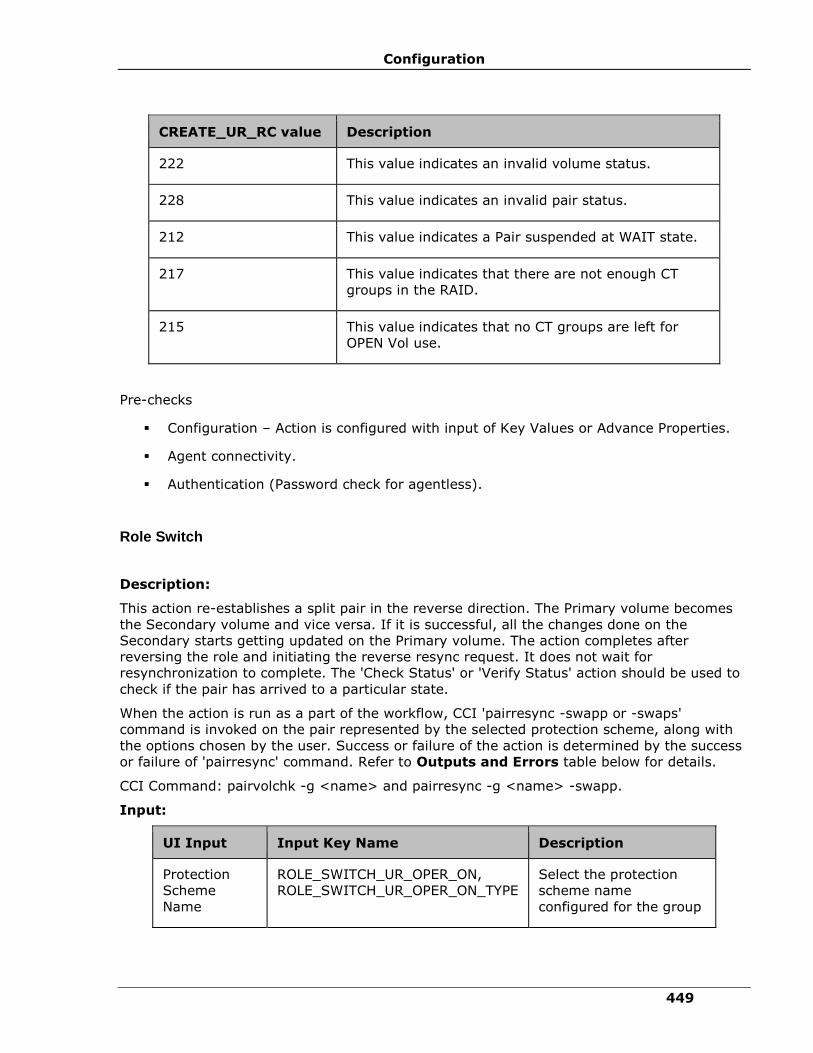
Configuration
449
CREATE_UR_RC value Description
222 This value indicates an invalid volume status.
228 This value indicates an invalid pair status.
212 This value indicates a Pair suspended at WAIT state.
217 This value indicates that there are not enough CT
groups in the RAID.
215 This value indicates that no CT groups are left for
OPEN Vol use.
Pre-checks
▪ Configuration – Action is configured with input of Key Values or Advance Properties.
▪ Agent connectivity.
▪ Authentication (Password check for agentless).
Role Switch
Description:
This action re-establishes a split pair in the reverse direction. The Primary volume becomes
the Secondary volume and vice versa. If it is successful, all the changes done on the
Secondary starts getting updated on the Primary volume. The action completes after
reversing the role and initiating the reverse resync request. It does not wait for
resynchronization to complete. The 'Check Status' or 'Verify Status' action should be used to
check if the pair has arrived to a particular state.
When the action is run as a part of the workflow, CCI 'pairresync -swapp or -swaps'
command is invoked on the pair represented by the selected protection scheme, along with
the options chosen by the user. Success or failure of the action is determined by the success
or failure of 'pairresync' command. Refer to Outputs and Errors table below for details.
CCI Command: pairvolchk -g <name> and pairresync -g <name> -swapp.
Input:
UI Input Input Key Name Description
Protection
Scheme
Name
ROLE_SWITCH_UR_OPER_ON,
ROLE_SWITCH_UR_OPER_ON_TYPE
Select the protection
scheme name
configured for the group

IBM Resiliency Orchestration Administrator’s Guide
© IBM Corporation 2017 450
UI Input Input Key Name Description
from the drop-down list.
Note:
If the group is attached
with more than one pair
of protection subsystem
then do not select
"Current Production
Service" or "Current DR
Service". Instead, select
the actual protection
subsystem to configure
the operation.
Outputs and Errors:
The ROLE_SWITCH_UR_RC key is set with an exit status of 'pairresync' command.
Following are the possible values:
▪ A return code '0' indicates success.
▪ All other values indicates failure.
ROLE_SWITCH_UR_RC
value Description
0 This value indicates that the role for all
the pairs in the group are successfully
reversed.
non zero This value indicates some failure in
resync of group.
236 This value indicates an unmatched
volume status within the group.
229 This value indicates an inconsistent
status in group.
222 This value indicates an invalid volume
status.
228 This value indicates an invalid pair
status.
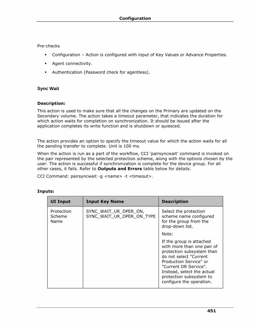
Configuration
451
Pre-checks
▪ Configuration – Action is configured with input of Key Values or Advance Properties.
▪ Agent connectivity.
▪ Authentication (Password check for agentless).
Sync Wait
Description:
This action is used to make sure that all the changes on the Primary are updated on the
Secondary volume. The action takes a timeout parameter, that indicates the duration for
which action waits for completion on synchronization. It should be issued after the
application completes its write function and is shutdown or quiesced.
The action provides an option to specify the timeout value for which the action waits for all
the pending transfer to complete. Unit is 100 ms.
When the action is run as a part of the workflow, CCI 'pairsyncwait' command is invoked on
the pair represented by the selected protection scheme, along with the options chosen by the
user. The action is successful if synchronization is complete for the device group. For all
other cases, it fails. Refer to Outputs and Errors table below for details.
CCI Command: pairsyncwait -g <name> -t <timeout>.
Inputs:
UI Input Input Key Name Description
Protection
Scheme
Name
SYNC_WAIT_UR_OPER_ON,
SYNC_WAIT_UR_OPER_ON_TYPE
Select the protection
scheme name configured
for the group from the
drop-down list.
Note:
If the group is attached
with more than one pair of
protection subsystem then
do not select "Current
Production Service" or
"Current DR Service".
Instead, select the actual
protection subsystem to
configure the operation.
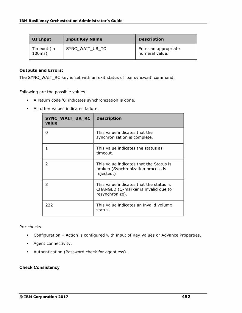
IBM Resiliency Orchestration Administrator’s Guide
© IBM Corporation 2017 452
UI Input Input Key Name Description
Timeout (in
100ms)
SYNC_WAIT_UR_TO Enter an appropriate
numeral value.
Outputs and Errors:
The SYNC_WAIT_RC key is set with an exit status of 'pairsyncwait' command.
Following are the possible values:
▪ A return code '0' indicates synchronization is done.
▪ All other values indicates failure.
SYNC_WAIT_UR_RC
value
Description
0 This value indicates that the
synchronization is complete.
1 This value indicates the status as
timeout.
2 This value indicates that the Status is
broken (Synchronization process is
rejected.)
3 This value indicates that the status is
CHANGED (Q-marker is invalid due to
resynchronize).
222 This value indicates an invalid volume
status.
Pre-checks
▪ Configuration – Action is configured with input of Key Values or Advance Properties.
▪ Agent connectivity.
▪ Authentication (Password check for agentless).
Check Consistency
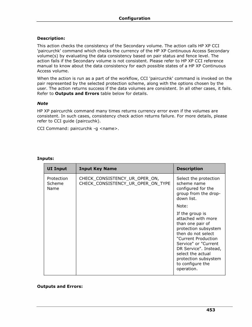
Configuration
453
Description:
This action checks the consistency of the Secondary volume. The action calls HP XP CCI
'paircurchk' command which checks the currency of the HP XP Continuous Access Secondary
volume(s) by evaluating the data consistency based on pair status and fence level. The
action fails if the Secondary volume is not consistent. Please refer to HP XP CCI reference
manual to know about the data consistency for each possible states of a HP XP Continuous
Access volume.
When the action is run as a part of the workflow, CCI 'paircurchk' command is invoked on the
pair represented by the selected protection scheme, along with the options chosen by the
user. The action returns success if the data volumes are consistent. In all other cases, it fails.
Refer to Outputs and Errors table below for details.
Note
HP XP paircurchk command many times returns currency error even if the volumes are
consistent. In such cases, consistency check action returns failure. For more details, please
refer to CCI guide (paircuchk).
CCI Command: paircurchk -g <name>.
Inputs:
UI Input Input Key Name Description
Protection
Scheme
Name
CHECK_CONSISTENCY_UR_OPER_ON,
CHECK_CONSISTENCY_UR_OPER_ON_TYPE
Select the protection
scheme name
configured for the
group from the drop-
down list.
Note:
If the group is
attached with more
than one pair of
protection subsystem
then do not select
"Current Production
Service" or "Current
DR Service". Instead,
select the actual
protection subsystem
to configure the
operation.
Outputs and Errors:

IBM Resiliency Orchestration Administrator’s Guide
© IBM Corporation 2017 454
The CHECK_CONSISTENCY_UR_RC key is set with an exit status of paircurchk command.
Following are possible values:
▪ A return code '0' indicate Secondary volumes are consistent.
▪ All other value indicates failure or warnings.
CHECK_CONSISTENCY_UR_RC value Description
0 This value indicates that the
data is consistent.
225 This value indicates a S-Vol
currency error.
Pre-checks
▪ Configuration – Action is configured with input of Key Values or Advance Properties.
▪ Agent connectivity.
▪ Authentication (Password check for agentless).
Is XP Continuous Access Journal
Description:
This action checks whether the protection service name represented is a XP Continuous
Access Journal protection service. The action fails if it is of different type.
Inputs:
UI Input Input Key Name Description
Protection
Scheme
Name
IS_UR_OPER_ON ,
IS_UR_OPER_ON_TYPE (
DYNAMIC or STATIC )
It should always be
configured as static and then
the production scheme name
has to be given.
Note:
Does not support the
Dynamic operation.
Outputs and Errors:
None
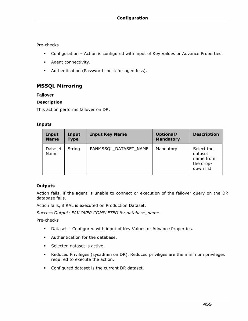
Configuration
455
Pre-checks
▪ Configuration – Action is configured with input of Key Values or Advance Properties.
▪ Agent connectivity.
▪ Authentication (Password check for agentless).
MSSQL Mirroring
Failover
Description
This action performs failover on DR.
Inputs
Input
Name
Input
Type
Input Key Name Optional/
Mandatory
Description
Dataset
Name
String PANMSSQL_DATASET_NAME Mandatory Select the
dataset
name from
the drop-
down list.
Outputs
Action fails, if the agent is unable to connect or execution of the failover query on the DR
database fails.
Action fails, if RAL is executed on Production Dataset.
Success Output: FAILOVER COMPLETED for database_name
Pre-checks
▪ Dataset – Configured with input of Key Values or Advance Properties.
▪ Authentication for the database.
▪ Selected dataset is active.
▪ Reduced Privileges (sysadmin on DR). Reduced priviliges are the minimum privileges
required to execute the action.
▪ Configured dataset is the current DR dataset.
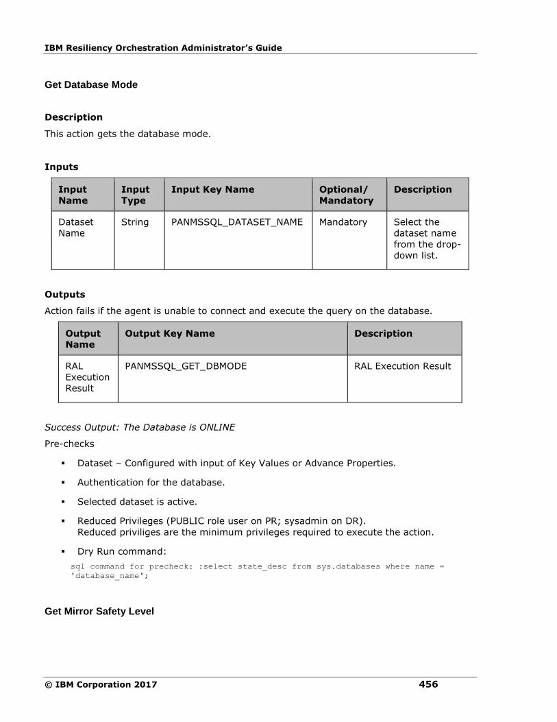
IBM Resiliency Orchestration Administrator’s Guide
© IBM Corporation 2017 456
Get Database Mode
Description
This action gets the database mode.
Inputs
Input
Name
Input
Type
Input Key Name Optional/
Mandatory
Description
Dataset
Name
String PANMSSQL_DATASET_NAME Mandatory Select the
dataset name
from the drop-
down list.
Outputs
Action fails if the agent is unable to connect and execute the query on the database.
Output
Name
Output Key Name Description
RAL
Execution
Result
PANMSSQL_GET_DBMODE RAL Execution Result
Success Output: The Database is ONLINE
Pre-checks
▪ Dataset – Configured with input of Key Values or Advance Properties.
▪ Authentication for the database.
▪ Selected dataset is active.
▪ Reduced Privileges (PUBLIC role user on PR; sysadmin on DR).
Reduced priviliges are the minimum privileges required to execute the action.
▪ Dry Run command:
sql command for precheck: :select state_desc from sys.databases where name =
'database_name';
Get Mirror Safety Level

Configuration
457
Description
This RAL action gets the current mirror safety level.
Inputs
Input
Name
Input
Type
Input Key Name Optional/
Mandatory
Description
Dataset
Name
String PANMSSQL_DATASET_NAME Mandatory Select the
dataset
name from
the drop-
down list.
Outputs
Output
Name
Output Key Name Description
RAL
Execution
Result
PANMSSQL_GET_MIRROR_SAFETY_LEVEL RAL Execution
Result
Action fails, if the agent is unable to connect or execute a query on the database.
Success Output: Mirroring Safety Level: FULL for database: <database_name> on
component <component_name> (IP_Address)
Pre-checks
▪ Dataset – Configured with input of Key Values or Advance Properties.
▪ Authentication for the database.
▪ Selected dataset is active.
▪ Reduced Privileges (PUBLIC role user on PR; sysadmin on DR).
Reduced priviliges are the minimum privileges required to execute the action.
▪ Dry Run command:
sql command for precheck: :select top 1
mirroring_role_desc,mirroring_state_desc,mirroring_safety_level_desc from
sys.database_mirroring,sys.databases where
sys.databases.database_id=sys.database_mirroring.database_id and name =
'database_name';

IBM Resiliency Orchestration Administrator’s Guide
© IBM Corporation 2017 458
Get Mirroring Status
Description
This RAL action provides the current mirroring status.
Inputs
Input
Name
Input
Type
Input Key Name Optional/
Mandatory
Description
Dataset
Name
String PANMSSQL_DATASET_NAME Mandatory Select the
dataset
name from
the drop-
down list.
Outputs
Output
Name
Output Key Name Description
RAL
Execution
Result
PANMSSQL_GET_MIRRORSTATUS RAL Execution Result
Action fails, if the agent is unable to connect or execute a query on the database.
Success Output: Mirroring Status for database <database_name> is SYNCHRONIZED on
component <component_name> (IP_Address)
Pre-checks
▪ Dataset – Configured with input of Key Values or Advance Properties.
▪ Authentication for the database.
▪ Selected dataset is active.
▪ Reduced Privileges (PUBLIC role user on PR; sysadmin on DR).
Reduced priviliges are the minimum privileges required to execute the action.
▪ Dry Run command:
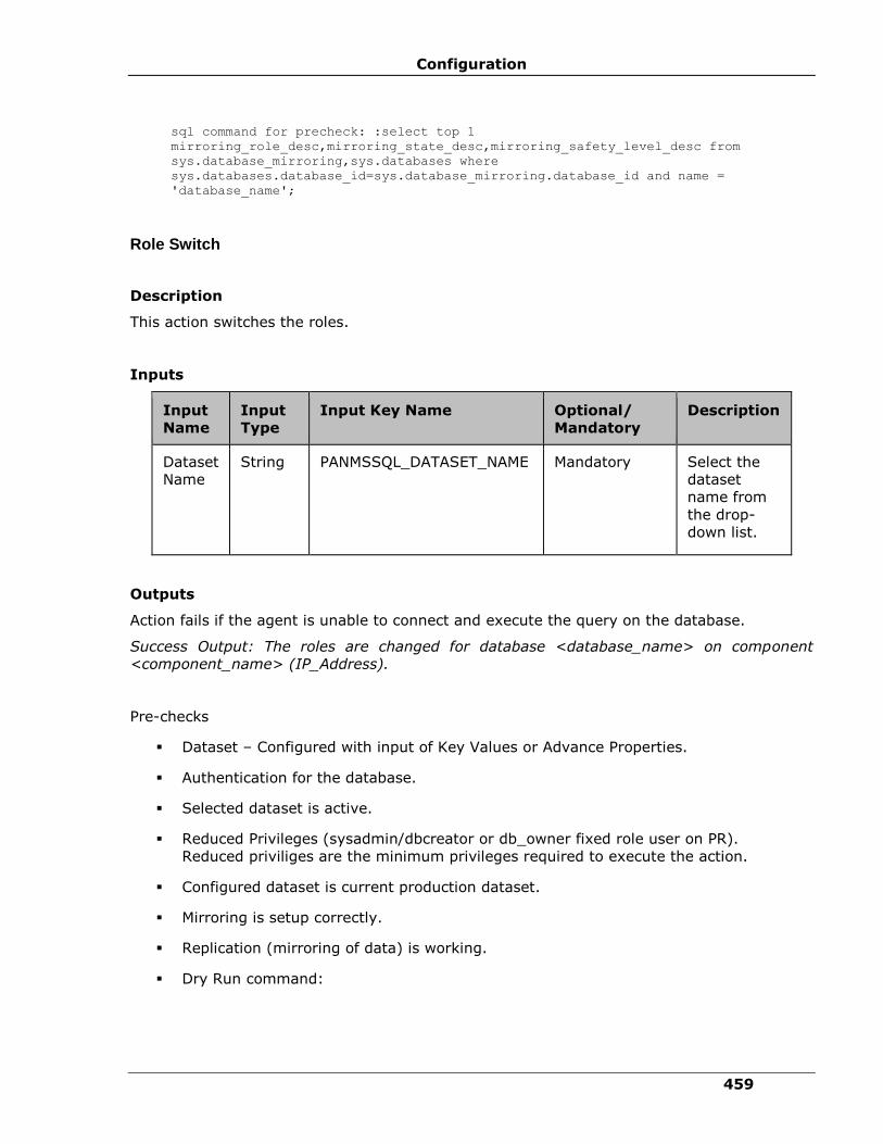
Configuration
459
sql command for precheck: :select top 1
mirroring_role_desc,mirroring_state_desc,mirroring_safety_level_desc from
sys.database_mirroring,sys.databases where
sys.databases.database_id=sys.database_mirroring.database_id and name =
'database_name';
Role Switch
Description
This action switches the roles.
Inputs
Input
Name
Input
Type
Input Key Name Optional/
Mandatory
Description
Dataset
Name
String PANMSSQL_DATASET_NAME Mandatory Select the
dataset
name from
the drop-
down list.
Outputs
Action fails if the agent is unable to connect and execute the query on the database.
Success Output: The roles are changed for database <database_name> on component
<component_name> (IP_Address).
Pre-checks
▪ Dataset – Configured with input of Key Values or Advance Properties.
▪ Authentication for the database.
▪ Selected dataset is active.
▪ Reduced Privileges (sysadmin/dbcreator or db_owner fixed role user on PR).
Reduced priviliges are the minimum privileges required to execute the action.
▪ Configured dataset is current production dataset.
▪ Mirroring is setup correctly.
▪ Replication (mirroring of data) is working.
▪ Dry Run command:
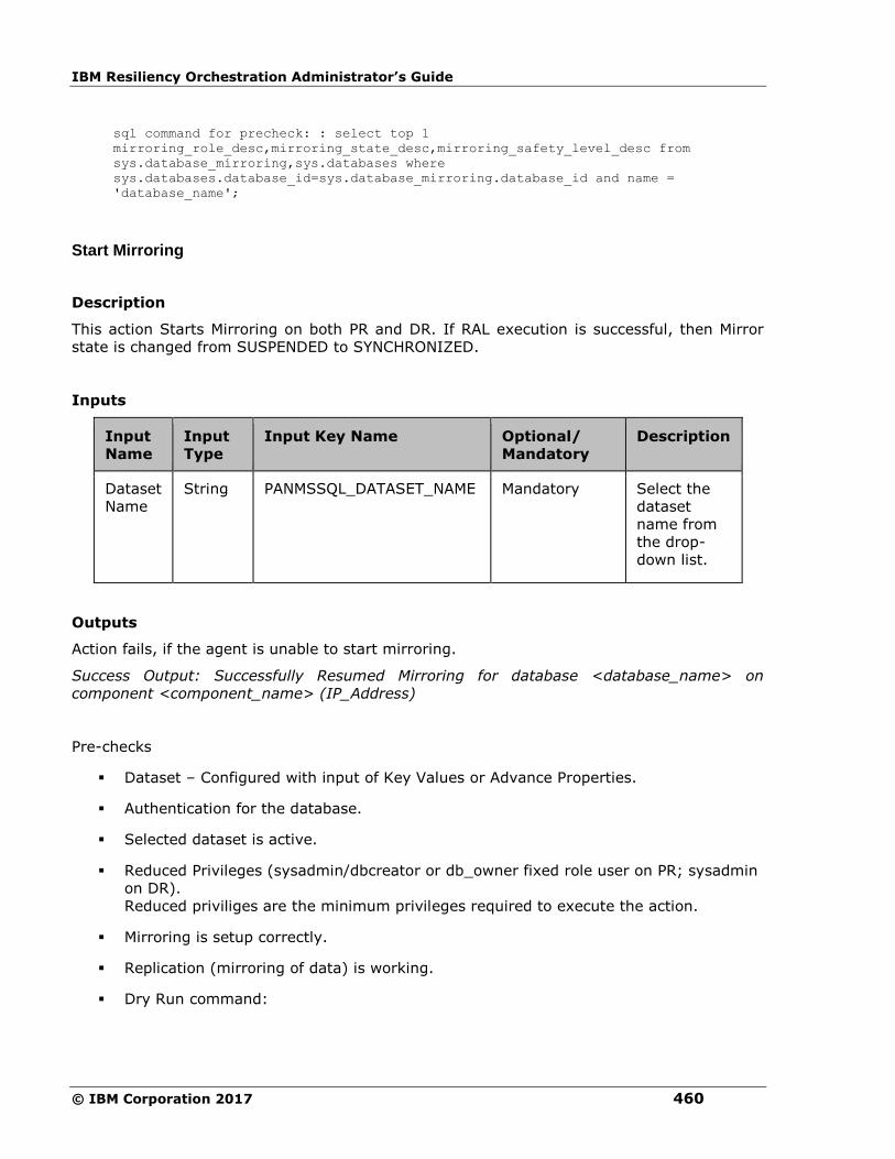
IBM Resiliency Orchestration Administrator’s Guide
© IBM Corporation 2017 460
sql command for precheck: : select top 1
mirroring_role_desc,mirroring_state_desc,mirroring_safety_level_desc from
sys.database_mirroring,sys.databases where
sys.databases.database_id=sys.database_mirroring.database_id and name =
'database_name';
Start Mirroring
Description
This action Starts Mirroring on both PR and DR. If RAL execution is successful, then Mirror
state is changed from SUSPENDED to SYNCHRONIZED.
Inputs
Input
Name
Input
Type
Input Key Name Optional/
Mandatory
Description
Dataset
Name
String PANMSSQL_DATASET_NAME Mandatory Select the
dataset
name from
the drop-
down list.
Outputs
Action fails, if the agent is unable to start mirroring.
Success Output: Successfully Resumed Mirroring for database <database_name> on
component <component_name> (IP_Address)
Pre-checks
▪ Dataset – Configured with input of Key Values or Advance Properties.
▪ Authentication for the database.
▪ Selected dataset is active.
▪ Reduced Privileges (sysadmin/dbcreator or db_owner fixed role user on PR; sysadmin
on DR).
Reduced priviliges are the minimum privileges required to execute the action.
▪ Mirroring is setup correctly.
▪ Replication (mirroring of data) is working.
▪ Dry Run command:
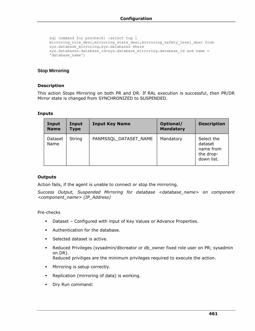
Configuration
461
sql command for precheck: :select top 1
mirroring_role_desc,mirroring_state_desc,mirroring_safety_level_desc from
sys.database_mirroring,sys.databases where
sys.databases.database_id=sys.database_mirroring.database_id and name =
'database_name';
Stop Mirroring
Description
This action Stops Mirroring on both PR and DR. If RAL execution is successful, then PR/DR
Mirror state is changed from SYNCHRONIZED to SUSPENDED.
Inputs
Input
Name
Input
Type
Input Key Name Optional/
Mandatory
Description
Dataset
Name
String PANMSSQL_DATASET_NAME Mandatory Select the
dataset
name from
the drop-
down list.
Outputs
Action fails, if the agent is unable to connect or stop the mirroring.
Success Output, Suspended Mirroring for database <database_name> on component
<component_name> (IP_Address)
Pre-checks
▪ Dataset – Configured with input of Key Values or Advance Properties.
▪ Authentication for the database.
▪ Selected dataset is active.
▪ Reduced Privileges (sysadmin/dbcreator or db_owner fixed role user on PR; sysadmin
on DR).
Reduced priviliges are the minimum privileges required to execute the action.
▪ Mirroring is setup correctly.
▪ Replication (mirroring of data) is working.
▪ Dry Run command:
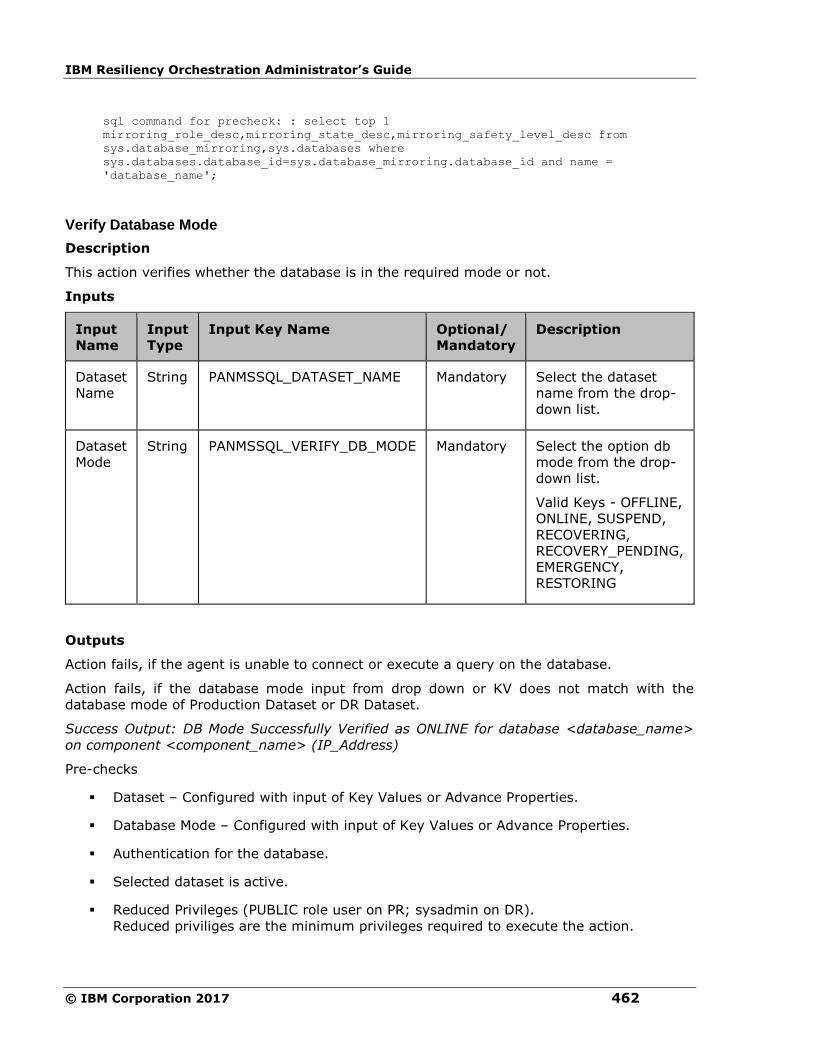
IBM Resiliency Orchestration Administrator’s Guide
© IBM Corporation 2017 462
sql command for precheck: : select top 1
mirroring_role_desc,mirroring_state_desc,mirroring_safety_level_desc from
sys.database_mirroring,sys.databases where
sys.databases.database_id=sys.database_mirroring.database_id and name =
'database_name';
Verify Database Mode
Description
This action verifies whether the database is in the required mode or not.
Inputs
Input
Name
Input
Type
Input Key Name Optional/
Mandatory
Description
Dataset
Name
String PANMSSQL_DATASET_NAME Mandatory Select the dataset
name from the drop-
down list.
Dataset
Mode
String PANMSSQL_VERIFY_DB_MODE Mandatory Select the option db
mode from the drop-
down list.
Valid Keys - OFFLINE,
ONLINE, SUSPEND,
RECOVERING,
RECOVERY_PENDING,
EMERGENCY,
RESTORING
Outputs
Action fails, if the agent is unable to connect or execute a query on the database.
Action fails, if the database mode input from drop down or KV does not match with the
database mode of Production Dataset or DR Dataset.
Success Output: DB Mode Successfully Verified as ONLINE for database <database_name>
on component <component_name> (IP_Address)
Pre-checks
▪ Dataset – Configured with input of Key Values or Advance Properties.
▪ Database Mode – Configured with input of Key Values or Advance Properties.
▪ Authentication for the database.
▪ Selected dataset is active.
▪ Reduced Privileges (PUBLIC role user on PR; sysadmin on DR).
Reduced priviliges are the minimum privileges required to execute the action.

Configuration
463
▪ Dry Run command:
sql command for precheck: :select state_desc from sys.databases where name =
'database_name';
Verify Mirror Safety Level
Description
This action verifies the Mirror Safety Level of the database.For this database is selected and
respective mirroring safety level is provided by the user.
Inputs
Input
Name
Input
Type
Input Key Name Optional/
Mandatory
Description
Dataset
Name
String PANMSSQL_DATASET_NAME Mandatory Select the
dataset
name from
the drop-
down list.
Mirroring
Status
String PANMSSQL_VERIFY_MIRROR_SAFETY_LEVEL Mandatory Select the
mirror
status from
the drop-
down list.
Valid Keys -
FULL, OFF
Outputs
Action fails, if the agent is unable to connect or execute a query on the database.
Action fails, if the Mirror Safety Level input from drop down or KV does not match with the
Mirror Safety Level of database.
Success Output: Mirror Safety Level Successfully Verified as FULL for database
<database_name> on component <component_name> (IP_Address)
Pre-checks
▪ Dataset – Configured with input of Key Values or Advance Properties.
▪ Authentication for the database.
▪ Mirror Safety Level – configured with input Key Values or Advance Properties.

IBM Resiliency Orchestration Administrator’s Guide
© IBM Corporation 2017 464
▪ Selected dataset is active.
▪ Reduced Privileges (PUBLIC role user on PR; sysadmin on DR).
Reduced priviliges are the minimum privileges required to execute the action.
▪ Dry Run command:
sql command for precheck: :select top 1
mirroring_role_desc,mirroring_state_desc,mirroring_safety_level_desc from
sys.database_mirroring,sys.databases where
sys.databases.database_id=sys.database_mirroring.database_id and name =
'database_name';
Set Mirror Safety Level
Description
This action Sets the Mirror Safety Level of the database.
Inputs
Input
Name
Input
Type
Input Key Name Optional/
Mandatory
Description
Dataset
Name String PANMSSQL_DATASET_NAME Mandatory Select the
dataset
name from
the drop-
down list.
Safety
Level
String PANMSSQL_SET_MIRROR_SAFETY_LEVEL Mandatory Select the
safety level
from the
drop-down
list.
Valid Keys -
FULL,OFF
Outputs
Action fails, if the agent is unable to connect or execute a query on the database.
Success Output: Safety Level Updated Successfully for database:<database_name> on
component <component_name> (IP_Address)
Pre-checks
▪ Dataset – Configured with input of Key Values or Advance Properties.

Configuration
465
▪ Authentication for the database.
▪ Selected dataset is active.
▪ Reduced Privileges (sysadmin/dbcreator or db_owner fixed role user on PR).
Reduced priviliges are the minimum privileges required to execute the action.
▪ Configured dataset is the current Production dataset.
▪ MSSQL Enterprise Edition.
▪ This RAL Action can only be executed for SQL Server 2005 Enterprise Edition Service
Pack 1 (SP1) and later versions"
Verify Mirroring Status
Description
This action verifies whether the database is in the required status or not. For this database is
selected and respective mirroring state is provided by the user. The current mirroring status
is matched with user input for verification.
Inputs
Input
Name
Input
Type
Input Key Name Optional/
Mandatory
Description
Dataset
Name
String PANMSSQL_DATASET_NAME Mandatory Select the dataset
name from the
drop-down list.
Mirroring
Status
String PANMSSQL_VERIFY_MIRROR_STATUS Mandatory Select the mirror
status from the
drop-down list.
Valid Keys -
SYNCHRONIZED,
SYNCHRONIZING,
UNSYNCHRONIZED,
SUSPENDED,
DISCONNECTED,
PENDING_FAILOVER
Outputs
Action fails, if the agent is unable to connect or execute a query on the database.
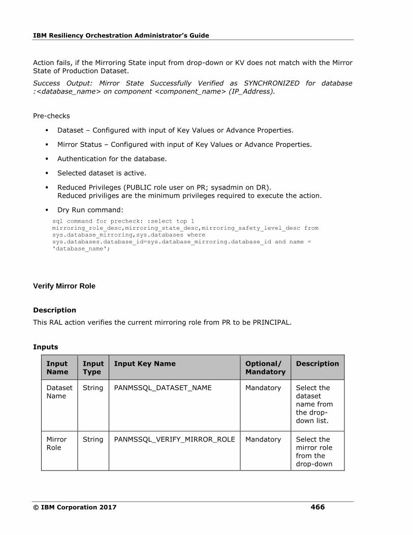
IBM Resiliency Orchestration Administrator’s Guide
© IBM Corporation 2017 466
Action fails, if the Mirroring State input from drop-down or KV does not match with the Mirror
State of Production Dataset.
Success Output: Mirror State Successfully Verified as SYNCHRONIZED for database
:<database_name> on component <component_name> (IP_Address).
Pre-checks
▪ Dataset – Configured with input of Key Values or Advance Properties.
▪ Mirror Status – Configured with input of Key Values or Advance Properties.
▪ Authentication for the database.
▪ Selected dataset is active.
▪ Reduced Privileges (PUBLIC role user on PR; sysadmin on DR).
Reduced priviliges are the minimum privileges required to execute the action.
▪ Dry Run command:
sql command for precheck: :select top 1
mirroring_role_desc,mirroring_state_desc,mirroring_safety_level_desc from
sys.database_mirroring,sys.databases where
sys.databases.database_id=sys.database_mirroring.database_id and name =
'database_name';
Verify Mirror Role
Description
This RAL action verifies the current mirroring role from PR to be PRINCIPAL.
Inputs
Input
Name
Input
Type
Input Key Name Optional/
Mandatory
Description
Dataset
Name
String PANMSSQL_DATASET_NAME Mandatory Select the
dataset
name from
the drop-
down list.
Mirror
Role
String PANMSSQL_VERIFY_MIRROR_ROLE Mandatory Select the
mirror role
from the
drop-down

Configuration
467
Input
Name
Input
Type
Input Key Name Optional/
Mandatory
Description
list.
Valid Keys -
PRINCIPAL,
MIRROR
Outputs
Action fails, if the agent is unable to connect or execute a query on the database.
Success Output: Mirror Role Successfully Verified as PRINCIPAL for database
<database_name> on component <component_name> (IP_Address)
Pre-checks
▪ Dataset – Configured with input of Key Values or Advance Properties.
▪ Mirror Role – Configured with input of Key Values or Advance Properties.
▪ Authentication for the database.
▪ Selected dataset is active.
▪ Reduced Privileges (PUBLIC role user on PR; sysadmin on DR).
Reduced priviliges are the minimum privileges required to execute the action.
▪ Dry Run command:
sql command for precheck: :select top 1
mirroring_role_desc,mirroring_state_desc,mirroring_safety_level_desc from
sys.database_mirroring,sys.databases where
sys.databases.database_id=sys.database_mirroring.database_id and name =
'database_name';
MS Exchange
Verify Database State
Description
This action get the current Status of the database.
Inputs
Input
Name
Input
Type
Input Key Name Optional/
Mandatory
Description
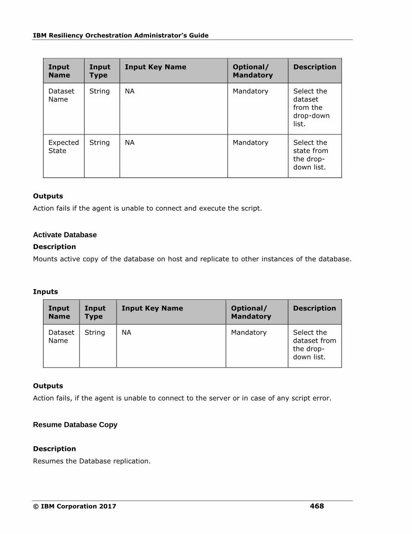
IBM Resiliency Orchestration Administrator’s Guide
© IBM Corporation 2017 468
Input
Name
Input
Type
Input Key Name Optional/
Mandatory
Description
Dataset
Name
String NA Mandatory Select the
dataset
from the
drop-down
list.
Expected
State
String NA Mandatory Select the
state from
the drop-
down list.
Outputs
Action fails if the agent is unable to connect and execute the script.
Activate Database
Description
Mounts active copy of the database on host and replicate to other instances of the database.
Inputs
Input
Name
Input
Type
Input Key Name Optional/
Mandatory
Description
Dataset
Name
String NA Mandatory Select the
dataset from
the drop-
down list.
Outputs
Action fails, if the agent is unable to connect to the server or in case of any script error.
Resume Database Copy
Description
Resumes the Database replication.

Configuration
469
Inputs
Input
Name
Input
Type
Input Key Name Optional/
Mandatory
Description
Dataset
Name
String NA Mandatory Select the
dataset from
the drop-
down list.
Outputs
Action fails, if the agent is unable to start the server.
Suspend Database Copy
Description
This action suspends the Database replication.
Inputs
Input
Name
Input
Type
Input Key Name Optional/
Mandatory
Description
Dataset
Name
String NA Mandatory Select the
dataset from
the drop-
down list.
Outputs
Action fails, if the agent is unable to start the server.
NetApp SnapMirror
LunMap
Description
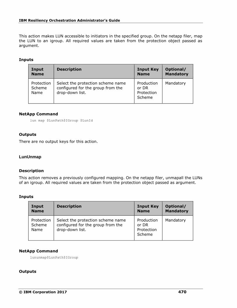
IBM Resiliency Orchestration Administrator’s Guide
© IBM Corporation 2017 470
This action makes LUN accessible to initiators in the specified group. On the netapp filer, map
the LUN to an igroup. All required values are taken from the protection object passed as
argument.
Inputs
Input
Name
Description Input Key
Name
Optional/
Mandatory
Protection
Scheme
Name
Select the protection scheme name
configured for the group from the
drop-down list.
Production
or DR
Protection
Scheme
Mandatory
NetApp Command
lun map $LunPath$IGroup $LunId
Outputs
There are no output keys for this action.
LunUnmap
Description
This action removes a previously configured mapping. On the netapp filer, unmapall the LUNs
of an igroup. All required values are taken from the protection object passed as argument.
Inputs
Input
Name
Description Input Key
Name
Optional/
Mandatory
Protection
Scheme
Name
Select the protection scheme name
configured for the group from the
drop-down list.
Production
or DR
Protection
Scheme
Mandatory
NetApp Command
lununmap$LunPath$IGroup
Outputs

Configuration
471
There are no output keys for this action.
Create Clone
Description
This action creates a new flexible volume that is a clone of parent_flexvol or
parent_snapshot. The clone name has to be provided by the RAL user or set in key value
CLONE_NAME.
Inputs
Input
Name
Description Input Key
Name
Optional/
Mandatory
Protection
Scheme
Name
Select the protection scheme
name configured for the group
from the drop-down list.
Production or
DR Protection
Scheme
Mandatory
Volume
Name
If the volume is different from the
one in the above protection
object, provide it here in
Advanced Properties or in key
value VOLUME_NAME.
VOLUME_NAME Optional
Clone
Name
The clone name has to be
provided by the RAL user in
Advanced Properties or set in key
value CLONE_NAME
CLONE_NAME Mandatory
LUN Path If the clone’s parent volume does
not belong to the protection object
and the clone was chosen during
workflow execution by the
“Choose Clone” RAL action then
the user should provide the full
LUN path or he can provide key
MOUNT_PATH. If clone parent
volume belongs to the protection
object then the action will build
the LUN path from the volume
name.
MOUNT_PATH Optional
NetApp Command
vol clone create $CloneName -s volume -b $VolumeName
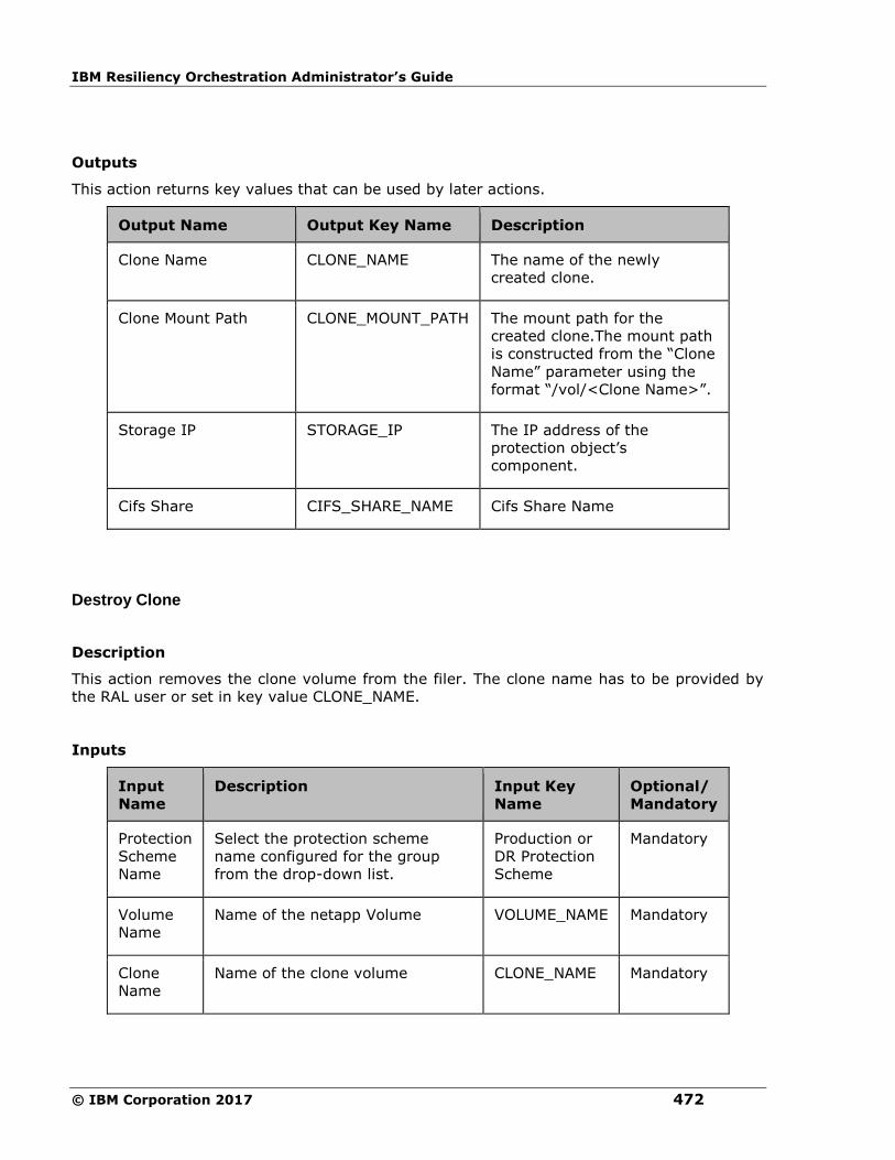
IBM Resiliency Orchestration Administrator’s Guide
© IBM Corporation 2017 472
Outputs
This action returns key values that can be used by later actions.
Output Name Output Key Name Description
Clone Name CLONE_NAME The name of the newly
created clone.
Clone Mount Path CLONE_MOUNT_PATH The mount path for the
created clone.The mount path
is constructed from the “Clone
Name” parameter using the
format “/vol/<Clone Name>”.
Storage IP STORAGE_IP The IP address of the
protection object’s
component.
Cifs Share CIFS_SHARE_NAME Cifs Share Name
Destroy Clone
Description
This action removes the clone volume from the filer. The clone name has to be provided by
the RAL user or set in key value CLONE_NAME.
Inputs
Input
Name
Description Input Key
Name
Optional/
Mandatory
Protection
Scheme
Name
Select the protection scheme
name configured for the group
from the drop-down list.
Production or
DR Protection
Scheme
Mandatory
Volume
Name
Name of the netapp Volume VOLUME_NAME Mandatory
Clone
Name
Name of the clone volume CLONE_NAME Mandatory

Configuration
473
NetApp Command
vol destroy $CloneName
Outputs
There are no output keys for this action.
Choose Clone
Description
This action allows the user to choose a clone from the list of existing clones of the volume or
create a new clone.
OR
If user wants to create a new clone, it is created from the latest available snapshot. This
action only works on the DR protection object.
Inputs
Input
Name
Description Input Key
Name
Optional/
Mandatory
Protection
Scheme
Name
Select the protection scheme name
configured for the group from the
drop-down list.
Production
or DR
Protection
Scheme
Mandatory
NetApp Command
If we select volume Clone option, need to execute below command in case creating new
volume clone:
vol clone create $CloneName -s volume -b $VolumeName
If we select LUN Clone option, need to execute below command in case creating new LUN
clone:
volume file clone create -volume volumeName -source-path /myfile -destination-
path /myfile_copy
Outputs
Output Name Output Key Name Description
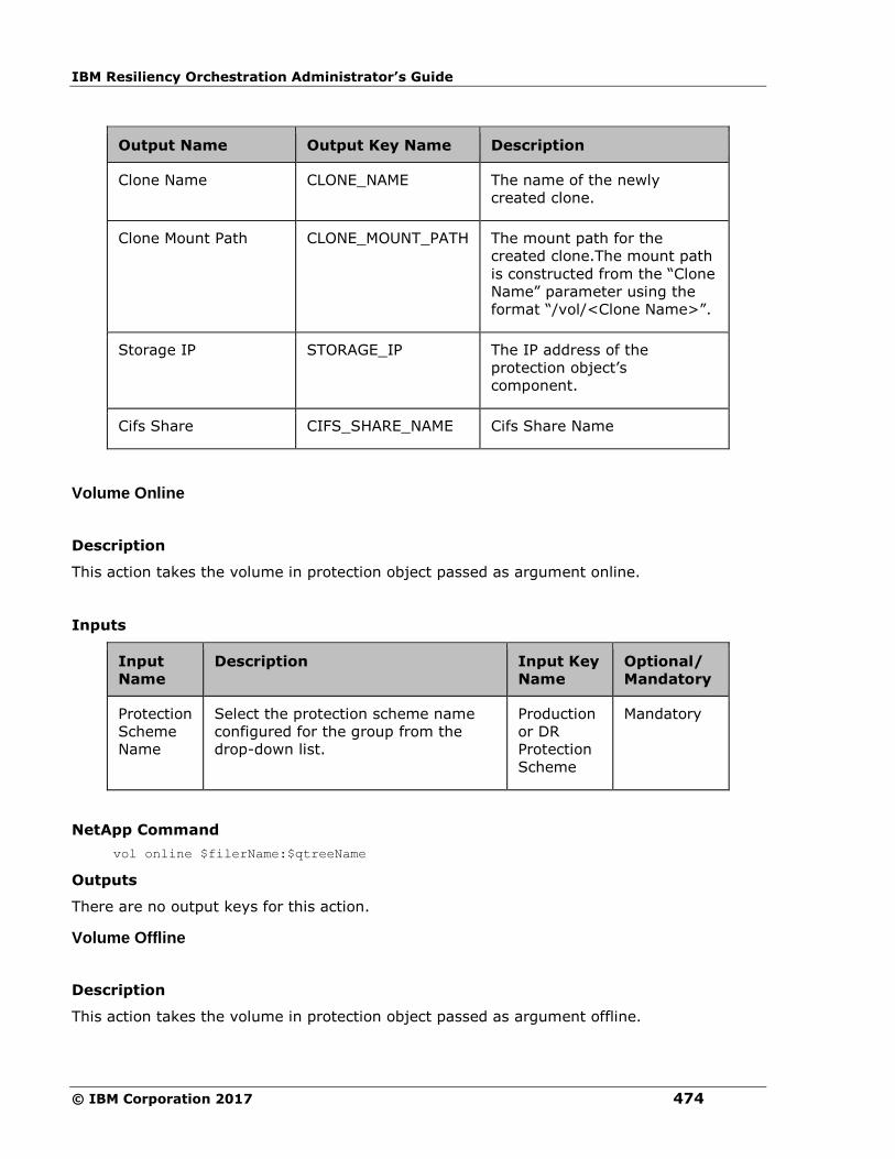
IBM Resiliency Orchestration Administrator’s Guide
© IBM Corporation 2017 474
Output Name Output Key Name Description
Clone Name CLONE_NAME The name of the newly
created clone.
Clone Mount Path CLONE_MOUNT_PATH The mount path for the
created clone.The mount path
is constructed from the “Clone
Name” parameter using the
format “/vol/<Clone Name>”.
Storage IP STORAGE_IP The IP address of the
protection object’s
component.
Cifs Share CIFS_SHARE_NAME Cifs Share Name
Volume Online
Description
This action takes the volume in protection object passed as argument online.
Inputs
Input
Name
Description Input Key
Name
Optional/
Mandatory
Protection
Scheme
Name
Select the protection scheme name
configured for the group from the
drop-down list.
Production
or DR
Protection
Scheme
Mandatory
NetApp Command
vol online $filerName:$qtreeName
Outputs
There are no output keys for this action.
Volume Offline
Description
This action takes the volume in protection object passed as argument offline.
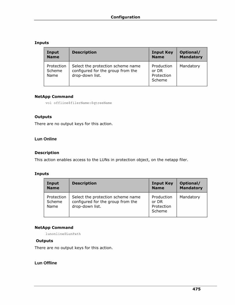
Configuration
475
Inputs
Input
Name
Description Input Key
Name
Optional/
Mandatory
Protection
Scheme
Name
Select the protection scheme name
configured for the group from the
drop-down list.
Production
or DR
Protection
Scheme
Mandatory
NetApp Command
vol offline$filerName:$qtreeName
Outputs
There are no output keys for this action.
Lun Online
Description
This action enables access to the LUNs in protection object, on the netapp filer.
Inputs
Input
Name
Description Input Key
Name
Optional/
Mandatory
Protection
Scheme
Name
Select the protection scheme name
configured for the group from the
drop-down list.
Production
or DR
Protection
Scheme
Mandatory
NetApp Command
lunonline$LunPath
Outputs
There are no output keys for this action.
Lun Offline
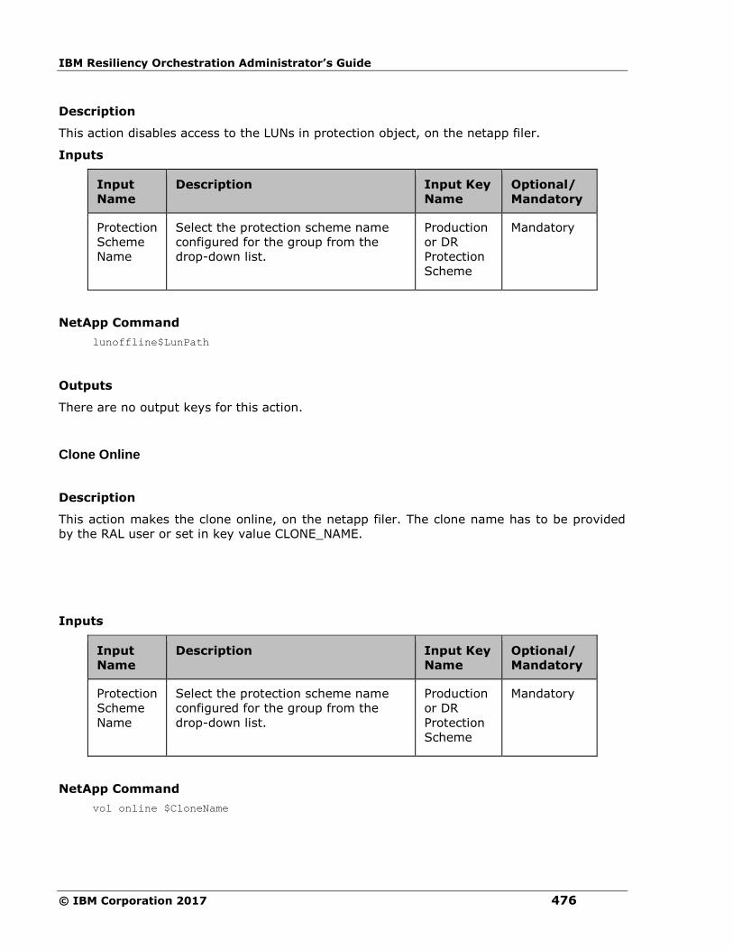
IBM Resiliency Orchestration Administrator’s Guide
© IBM Corporation 2017 476
Description
This action disables access to the LUNs in protection object, on the netapp filer.
Inputs
Input
Name
Description Input Key
Name
Optional/
Mandatory
Protection
Scheme
Name
Select the protection scheme name
configured for the group from the
drop-down list.
Production
or DR
Protection
Scheme
Mandatory
NetApp Command
lunoffline$LunPath
Outputs
There are no output keys for this action.
Clone Online
Description
This action makes the clone online, on the netapp filer. The clone name has to be provided
by the RAL user or set in key value CLONE_NAME.
Inputs
Input
Name
Description Input Key
Name
Optional/
Mandatory
Protection
Scheme
Name
Select the protection scheme name
configured for the group from the
drop-down list.
Production
or DR
Protection
Scheme
Mandatory
NetApp Command
vol online $CloneName

Configuration
477
Outputs
There are no output keys for this action.
Clone Online
Description
This action makes the clone offline, on the netapp filer. The clone name has to be provided
by the RAL user or set in key value CLONE_NAME..
Inputs
Input
Name
Description Input Key
Name
Optional/
Mandatory
Protection
Scheme
Name
Select the protection scheme name
configured for the group from the
drop-down list.
Production
or DR
Protection
Scheme
Mandatory
NetApp Command
vol offline $CloneName
Outputs
There are no output keys for this action.
Clone Map
Description
This action maps a clone LUN to the Initiator Group.
Inputs
Input Name Description Input Key Name Optional/
Mandatory
Protection
Scheme
Select the protection scheme name configured for the group from the
Production or DR
Protection Scheme
Mandatory
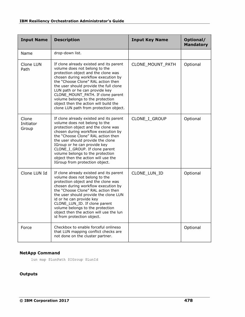
IBM Resiliency Orchestration Administrator’s Guide
© IBM Corporation 2017 478
Input Name Description Input Key Name Optional/
Mandatory
Name drop-down list.
Clone LUN
Path
If clone already existed and its parent volume does not belong to the
protection object and the clone was chosen during workflow execution by the “Choose Clone” RAL action then the user should provide the full clone LUN path or he can provide key CLONE_MOUNT_PATH. If clone parent
volume belongs to the protection
object then the action will build the clone LUN path from protection object.
CLONE_MOUNT_PATH Optional
Clone
Initiator
Group
If clone already existed and its parent volume does not belong to the protection object and the clone was
chosen during workflow execution by the “Choose Clone” RAL action then the user should provide the clone IGroup or he can provide key CLONE_I_GROUP. If clone parent volume belongs to the protection object then the action will use the
IGroup from protection object.
CLONE_I_GROUP Optional
Clone LUN Id If clone already existed and its parent volume does not belong to the protection object and the clone was chosen during workflow execution by
the “Choose Clone” RAL action then the user should provide the clone LUN id or he can provide key CLONE_LUN_ID. If clone parent volume belongs to the protection object then the action will use the lun id from protection object.
CLONE_LUN_ID Optional
Force Checkbox to enable forceful onlineso that LUN mapping conflict checks are
not done on the cluster partner.
Optional
NetApp Command
lun map $LunPath $IGroup $LunId
Outputs

Configuration
479
There are no output keys for this action.
Clone Unmap
Description
This action unmaps a clone LUN from the Initiator Group.
Inputs
Input Name Description Input Key Name Optional/
Mandatory
Protection
Scheme
Name
Select the protection
scheme name
configured for the
group from the drop-
down list.
Production or DR
Protection Scheme
Mandatory
Clone LUN
Path
If clone already
existed and its parent
volume does not
belong to the
protection object and
the clone was chosen
during workflow
execution by the
“Choose Clone” RAL
action then the user
should provide the full
clone LUN path or he
can provide key
CLONE_MOUNT_PATH.
If clone parent volume
belongs to the
protection object then
the action will build the
clone LUN path from
protection object.
CLONE_MOUNT_PATH Optional
Clone Initiator
Group
If clone already
existed and its parent
volume does not
belong to the
protection object and
the clone was chosen
during workflow
CLONE_I_GROUP Optional

IBM Resiliency Orchestration Administrator’s Guide
© IBM Corporation 2017 480
Input Name Description Input Key Name Optional/
Mandatory
execution by the
“Choose Clone” RAL
action then the user
should provide the
clone IGroup or he can
provide key
CLONE_I_GROUP. If
clone parent volume
belongs to the
protection object then
the action will use the
IGroup from protection
object.
NetApp Command
lununmap $LunPath $IGroup
Outputs
There are no output keys for this action.
Clone Lun Online
Description
This action enables access to clone LUN, on the netapp filer.
Inputs
Input Name Description Input Key Name Optional/ Mandatory
Protection
Scheme
Name
Select the protection scheme
name configured for the group
from the drop-down list.
Production or DR
Protection Scheme
Mandatory
Clone LUN
Path
If clone already existed and its
parent volume does not belong
to the protection object and
the clone was chosen during
workflow execution by the
“Choose Clone” RAL action
CLONE_MOUNT_PATH Optional

Configuration
481
Input Name Description Input Key Name Optional/ Mandatory
then the user should provide
the full clone LUN path or he
can provide key
CLONE_MOUNT_PATH. If clone
parent volume belongs to the
protection object then the
action will build the clone LUN
path from protection object.
Force Checkbox to enable forceful
onlineso that LUN mapping
conflict checks are not done on
the cluster partner.
Optional
NetApp Command
lunonline[-f] $CloneLunPath
Outputs
There are no output keys for this action.
Clone Lun Offline
Description
This action disables access to clone LUN, on the netapp filer.
Inputs
Input Name Description Input Key Name Optional/ Mandatory
Protection Scheme Name
Select the protection scheme name configured
for the group from the drop-down list.
Production or DR Protection Scheme
Mandatory
Clone LUN Path
If clone already existed and its parent volume does not belong to the protection object and the
clone was chosen during workflow execution by the “Choose Clone” RAL action
CLONE_MOUNT_PATH Optional
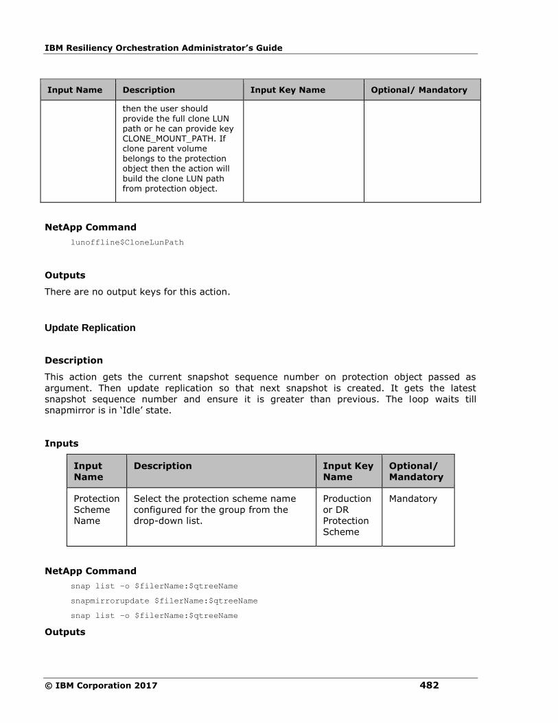
IBM Resiliency Orchestration Administrator’s Guide
© IBM Corporation 2017 482
Input Name Description Input Key Name Optional/ Mandatory
then the user should
provide the full clone LUN path or he can provide key CLONE_MOUNT_PATH. If clone parent volume belongs to the protection object then the action will
build the clone LUN path from protection object.
NetApp Command
lunoffline$CloneLunPath
Outputs
There are no output keys for this action.
Update Replication
Description
This action gets the current snapshot sequence number on protection object passed as
argument. Then update replication so that next snapshot is created. It gets the latest
snapshot sequence number and ensure it is greater than previous. The loop waits till
snapmirror is in ‘Idle’ state.
Inputs
Input
Name
Description Input Key
Name
Optional/
Mandatory
Protection
Scheme
Name
Select the protection scheme name
configured for the group from the
drop-down list.
Production
or DR
Protection
Scheme
Mandatory
NetApp Command
snap list –o $filerName:$qtreeName
snapmirrorupdate $filerName:$qtreeName
snap list –o $filerName:$qtreeName
Outputs

Configuration
483
There are no output keys for this action.
Quiesce Replication
Description
This action quiesces replication on protection object passed as argument.
Inputs
Input
Name
Description Input Key
Name
Optional/
Mandatory
Protection
Scheme
Name
Select the protection scheme name
configured for the group from the
drop-down list.
Production
or DR
Protection
Scheme
Mandatory
NetApp Command
snapmirrorquiesce $filerName:$qtreeName
Outputs
There are no output keys for this action.
Break Replication
Description
This action breaks replication on protection object passed as argument. The object’s volumes
become read write.
Inputs
Input
Name
Description Input Key
Name
Optional/
Mandatory
Protection
Scheme
Name
Select the protection scheme name
configured for the group from the
drop-down list.
Production
or DR
Protection
Scheme
Mandatory
NetApp Command

IBM Resiliency Orchestration Administrator’s Guide
© IBM Corporation 2017 484
snapmirrorbreak $filerName:$qtreeName
Outputs
There are no output keys for this action.
Resync Replication
Description
This action resynchronizes replication to protection object passed as argument.
Inputs
Input
Name
Description Input Key
Name
Optional/
Mandatory
Protection
Scheme
Name
Select the protection scheme name
configured for the group from the
drop-down list.
Production
or DR
Protection
Scheme
Mandatory
NetApp Command
snapmirrorresync -f $filerName:$qtreeName
Outputs
There are no output keys for this action.
Resume Replication
Description
This action resumes replication to protection object passed as argument.
Inputs
Input
Name
Description Input Key
Name
Optional/
Mandatory
Protection
Scheme
Select the protection scheme name
configured for the group from the
Production
or DR
Mandatory
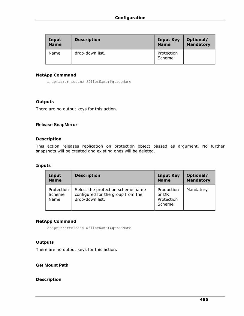
Configuration
485
Input
Name
Description Input Key
Name
Optional/
Mandatory
Name drop-down list. Protection
Scheme
NetApp Command
snapmirror resume $filerName:$qtreeName
Outputs
There are no output keys for this action.
Release SnapMirror
Description
This action releases replication on protection object passed as argument. No further
snapshots will be created and existing ones will be deleted.
Inputs
Input
Name
Description Input Key
Name
Optional/
Mandatory
Protection
Scheme
Name
Select the protection scheme name
configured for the group from the
drop-down list.
Production
or DR
Protection
Scheme
Mandatory
NetApp Command
snapmirrorrelease $filerName:$qtreeName
Outputs
There are no output keys for this action.
Get Mount Path
Description
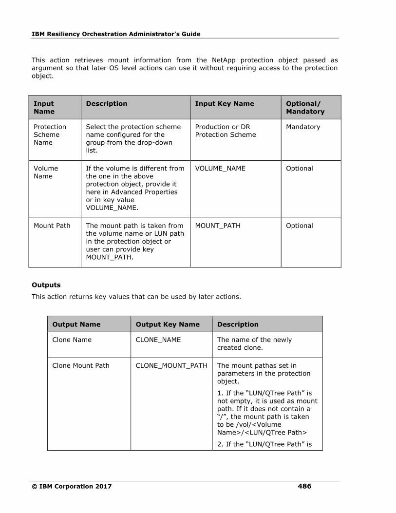
IBM Resiliency Orchestration Administrator’s Guide
© IBM Corporation 2017 486
This action retrieves mount information from the NetApp protection object passed as
argument so that later OS level actions can use it without requiring access to the protection
object.
Input
Name
Description Input Key Name Optional/
Mandatory
Protection
Scheme
Name
Select the protection scheme
name configured for the
group from the drop-down
list.
Production or DR
Protection Scheme
Mandatory
Volume
Name
If the volume is different from
the one in the above
protection object, provide it
here in Advanced Properties
or in key value
VOLUME_NAME.
VOLUME_NAME Optional
Mount Path The mount path is taken from
the volume name or LUN path
in the protection object or
user can provide key
MOUNT_PATH.
MOUNT_PATH Optional
Outputs
This action returns key values that can be used by later actions.
Output Name Output Key Name Description
Clone Name CLONE_NAME The name of the newly
created clone.
Clone Mount Path CLONE_MOUNT_PATH The mount pathas set in
parameters in the protection
object.
1. If the “LUN/QTree Path” is
not empty, it is used as mount
path. If it does not contain a
“/”, the mount path is taken
to be /vol/<Volume
Name>/<LUN/QTree Path>
2. If the “LUN/QTree Path” is

Configuration
487
Output Name Output Key Name Description
empty, the format
/vol/<Volume Name> is used
as mount path.
Storage IP STORAGE_IP The IP address of the
protection object’s
component.
Cifs Share CIFS_SHARE_NAME Cifs Share Name
Get Clone Mount Path
Description
Retrieves clone mount information from the NetApp protection object passed as argumentso
that later O.S. level actions can use it without requiring access to the protection object.
Input Name Description Input Key Name Optional/
Mandatory
Protection
Scheme Name
Select the protection
scheme name configured
for the group from the
drop-down list.
Production or DR
Protection Scheme
Mandatory
Volume Name If the volume is different
from the one in the above
protection object, provide it
here in Advanced
Properties or in key value
VOLUME_NAME.
VOLUME_NAME Optional
Clone Name The clone name has to be
provided by the RAL user
or set in key value
CLONE_NAME. It can also
be set by the Choose Clone
RAL action.
CLONE_NAME Optional
Clone Mount
Path
If mounting a clone volume
not belonging to the
protection object then the
user should provide the
CLONE_MOUNT_PATH Optional

IBM Resiliency Orchestration Administrator’s Guide
© IBM Corporation 2017 488
Input Name Description Input Key Name Optional/
Mandatory
mount path with IP address
in Advanced Properties or
in key
CLONE_MOUNT_PATH.
Outputs
This action returns key values that can be used by later actions.
Output Name Output Key Name Description
Storage IP STORAGE_IP The IP address of the
protection object’s
component.
Clone Mount Path CLONE_MOUNT_PATH The clone mount path as set
in parameters in the
protection object.
1. If the “LUN/QTree Path” is
not empty, it is used as clone
mount path. If it does not
contain a “/”, the clone mount
path is taken to be
/vol/<Clone
Name>/<LUN/QTree Path>
2. If the “LUN/QTree Path” is
empty, the format
/vol/<Clone Name> is used as
clone mount path.
Cifs Share CIFS_SHARE_NAME Cifs Share Name
CIFS Share Create
Description
This action creates a CIFS share on the netapp filer.
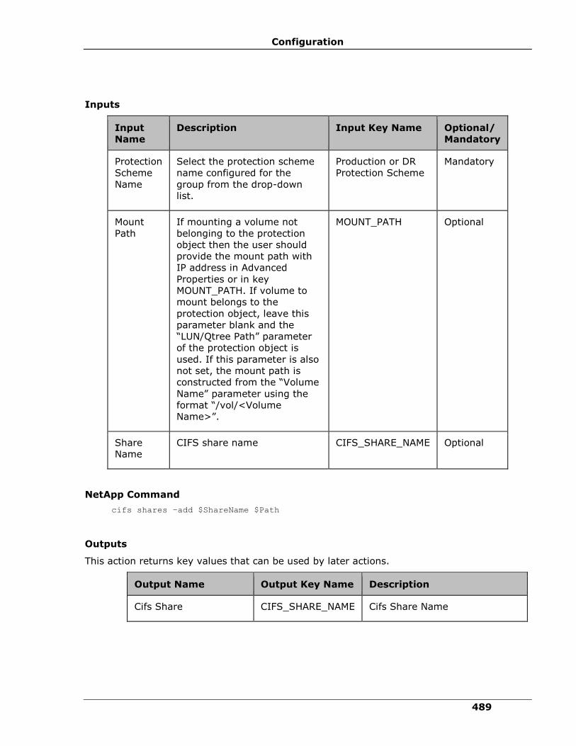
Configuration
489
Inputs
Input
Name
Description Input Key Name Optional/
Mandatory
Protection
Scheme
Name
Select the protection scheme
name configured for the
group from the drop-down
list.
Production or DR
Protection Scheme
Mandatory
Mount
Path
If mounting a volume not
belonging to the protection
object then the user should
provide the mount path with
IP address in Advanced
Properties or in key
MOUNT_PATH. If volume to
mount belongs to the
protection object, leave this
parameter blank and the
“LUN/Qtree Path” parameter
of the protection object is
used. If this parameter is also
not set, the mount path is
constructed from the “Volume
Name” parameter using the
format “/vol/<Volume
Name>”.
MOUNT_PATH Optional
Share
Name
CIFS share name CIFS_SHARE_NAME Optional
NetApp Command
cifs shares –add $ShareName $Path
Outputs
This action returns key values that can be used by later actions.
Output Name Output Key Name Description
Cifs Share CIFS_SHARE_NAME Cifs Share Name

IBM Resiliency Orchestration Administrator’s Guide
© IBM Corporation 2017 490
CIFS Share Delete
Description
This action deletes a CIFS share on the netapp filer.
Inputs
Input
Name
Description Input Key Name Optional/
Mandatory
Protection
Scheme
Name
Select the protection scheme
name configured for the
group from the drop-down
list.
Production or DR
Protection Scheme Mandatory
Share
Name
CIFS share name CIFS_SHARE_NAME Optional
NetApp Command
cifs shares –delete $ShareName
Outputs
There are no output keys for this action.
Clone CIFS Share Create
Description
This action creates a CIFS share on the netapp filer based on clone.
Inputs
Input
Name Description Input Key Name Optional/
Mandatory
Protection
Scheme
Name
Select the protection
scheme name configured
for the group from the
drop-down list.
Production or DR
Protection Scheme
Mandatory
Clone
Mount
If mounting a volume not
belonging to the protection
object then the user should
CLONE_MOUNT_PATH Optional
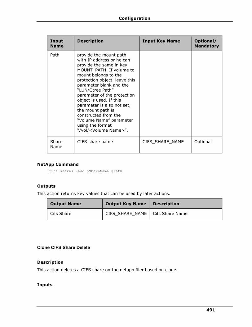
Configuration
491
Input
Name
Description Input Key Name Optional/
Mandatory
Path provide the mount path
with IP address or he can
provide the same in key
MOUNT_PATH. If volume to
mount belongs to the
protection object, leave this
parameter blank and the
“LUN/Qtree Path”
parameter of the protection
object is used. If this
parameter is also not set,
the mount path is
constructed from the
“Volume Name” parameter
using the format
“/vol/<Volume Name>”.
Share
Name
CIFS share name CIFS_SHARE_NAME Optional
NetApp Command
cifs shares –add $ShareName $Path
Outputs
This action returns key values that can be used by later actions.
Output Name Output Key Name Description
Cifs Share CIFS_SHARE_NAME Cifs Share Name
Clone CIFS Share Delete
Description
This action deletes a CIFS share on the netapp filer based on clone.
Inputs

IBM Resiliency Orchestration Administrator’s Guide
© IBM Corporation 2017 492
Input
Name
Description Input Key Name Optional/
Mandatory
Protection
Scheme
Name
Select the protection scheme
name configured for the
group from the drop-down
list.
Production or DR
Protection Scheme
Mandatory
Share
Name
CIFS share name CIFS_SHARE_NAME Optional
NetApp Command
cifs shares –delete $ShareName
Outputs
There are no output keys for this action.
Mount Junction Path
Description
This is used to mount volume on another volume with a junction-path.
Inputs
Input
Name
Description Input Key
Name
Optional/
Mandatory
Protection
Scheme
Name
Select the protection scheme
name configured for the group
from the drop-down list.
Production or
DR Protection
Scheme
Mandatory
Volume
Name
If the volume is different from
the one in the above protection
object, provide it here in
Advanced Properties or in key
value VOLUME_NAME.
VOLUME_NAME Optional
Junction
Path
This specifies the junction path
of the mounted volume. The
junction path name is case
JUNCTION_PATH Mandatory
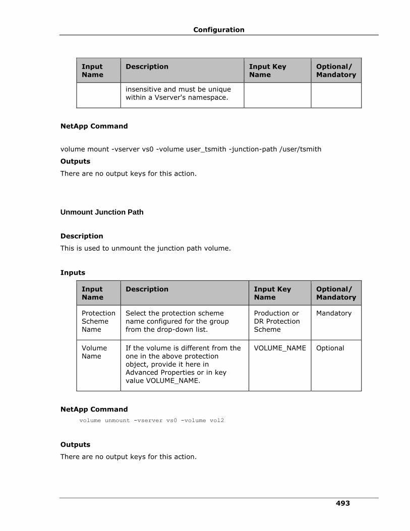
Configuration
493
Input
Name
Description Input Key
Name
Optional/
Mandatory
insensitive and must be unique
within a Vserver's namespace.
NetApp Command
volume mount -vserver vs0 -volume user_tsmith -junction-path /user/tsmith
Outputs
There are no output keys for this action.
Unmount Junction Path
Description
This is used to unmount the junction path volume.
Inputs
Input
Name
Description Input Key
Name
Optional/
Mandatory
Protection
Scheme
Name
Select the protection scheme
name configured for the group
from the drop-down list.
Production or
DR Protection
Scheme
Mandatory
Volume
Name
If the volume is different from the
one in the above protection
object, provide it here in
Advanced Properties or in key
value VOLUME_NAME.
VOLUME_NAME Optional
NetApp Command
volume unmount -vserver vs0 -volume vol2
Outputs
There are no output keys for this action.

IBM Resiliency Orchestration Administrator’s Guide
© IBM Corporation 2017 494
Create LUN Clone
Description
This action creates a new LUN Clone that is a clone of LUN. The LUN clone name has to be
provided by the RAL user or set in key value CLONE_NAME.
Inputs
Input Name Description Input Key Name Optional/
Mandatory
Protection
Scheme Name
Select the protection
scheme name
configured for the
group from the drop-
down list.
Production or DR
Protection Scheme
Mandatory
Volume Name If the volume is
different from the one
in the above
protection object,
provide it here in
Advanced Properties
or in key value
VOLUME_NAME.
VOL_NAME Optional
Lun path(s) If the clone’s parent
volume does not
belong to the
protection object and
the clone was chosen
during workflow
execution by the
“Choose Clone” RAL
action then the user
should provide the full
LUN path or he can
provide key
MOUNT_PATH. If clone
parent volume belongs
to the protection
object then the action
will build the LUN path
from the volume
name.
MOUNT_PATH Optional

Configuration
495
Input Name Description Input Key Name Optional/
Mandatory
Clone Name(s) The clone name has to
be provided by the
RAL user or set in key
value CLONE_NAME. It
can also be set by the
Choose Clone RAL
action.
CLONE_NAME Optional
NetApp Command
volume file clone create -volume $volumeName -source-path /myfile -destination-
path /myfile_copy
Outputs
This action returns key values that can be used by later actions.
Output Name Output Key Name Description
Clone Name CLONE_NAME The name of the newly
created clone.
Clone Mount Path CLONE_MOUNT_PATH The mount path for the
created clone.The mount path
is constructed from the “Clone
Name” parameter using the
format “/vol/<Clone Name>”.
Delete LUN Clone
Description
This action deletes a LUN Clone that is a clone of LUN.
Inputs
Input
Name
Description Input Key Name Optional/
Mandator
y
Protection
Scheme
Name
Select the protection
scheme name configured
for the group from the
Production or DR
Protection Scheme
Mandatory

IBM Resiliency Orchestration Administrator’s Guide
© IBM Corporation 2017 496
Input
Name
Description Input Key Name Optional/
Mandator
y
drop-down list.
Clone
LUN Path
If clone already existed
and its parent volume
does not belong to the
protection object and the
clone was chosen during
workflow execution by
the “Choose Clone” RAL
action then the user
should provide the full
clone LUN path or he can
provide key
CLONE_MOUNT_PATH. If
clone parent volume
belongs to the protection
object then the action
will build the clone LUN
path from protection
object.
CLONE_MOUNT_P
ATH
Optional
NetApp Command
volume file clone autodelete /vol/volume1/lun_clone -enable true -vserver vs1
Outputs
There are no output keys for this action.
PFR
PFR Operation
The PFR insertible action, displayed as PFR Operation in IBM Resiliency Orchestration,
provides flexibility to add customized PFR actions in the workflows. This action is applicable
only for generic (non-concrete) solution templates.
To configure the PFR Operation action, first add it in the workflow using Insert tab and
configure it using Properties tab. Perform the following steps in the Advanced tab in the
Action Properties section.
1. Select PFR Operation action in the workflow.
2. Click the Advanced tab.
3. From the Operation Type drop-down list, select the desired operation type.
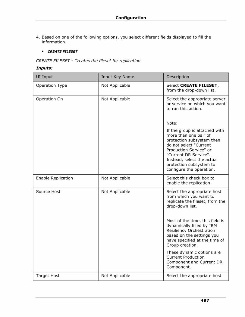
Configuration
497
4. Based on one of the following options, you select different fields displayed to fill the
information.
▪ CREATE FILESET
CREATE FILESET - Creates the fileset for replication.
Inputs:
UI Input Input Key Name Description
Operation Type Not Applicable Select CREATE FILESET,
from the drop-down list.
Operation On Not Applicable Select the appropriate server
or service on which you want
to run this action.
Note:
If the group is attached with
more than one pair of
protection subsystem then
do not select "Current
Production Service" or
"Current DR Service".
Instead, select the actual
protection subsystem to
configure the operation.
Enable Replication Not Applicable Select this check box to
enable the replication.
Source Host Not Applicable Select the appropriate host
from which you want to
replicate the fileset, from the
drop-down list.
Most of the time, this field is
dynamically filled by IBM
Resiliency Orchestration
based on the settings you
have specified at the time of
Group creation.
These dynamic options are
Current Production
Component and Current DR
Component.
Target Host Not Applicable Select the appropriate host

IBM Resiliency Orchestration Administrator’s Guide
© IBM Corporation 2017 498
UI Input Input Key Name Description
to which you want to
replicate the fileset, from the
drop-down list.
Most of the time, this field is
dynamically filled by IBM
Resiliency Orchestration
based on the settings you
have specified at the time of
Group creation.
These dynamic options are
Current Production
Component and Current DR
Component.
Replication State Not Applicable Select the replication state
from the drop-down list.
The Options are ENABLED,
and DISABLED.
Replication Interval Not Applicable Enter the desired value in
seconds.
Source Dir/File Not Applicable
Enter the directory or file
from which you want to
replicate.
Target Dir/File Not Applicable
Enter the directory or file to
which you want to replicate
the data.
▪ Click Add.
▪ Click Remove, if you want to discard the Source and Target Directory/ File path
you have mapped and configure it afresh.
▪ Click Advanced Configuration to filter the replication configuration.
Note:
The Advanced Configuration is applicable for only CREATE FILESET, MODIFY FILESET, and
TRANSFER FILESET.
The Advanced Configuration is NOT applicable for DELETE FILESET, STOP FILESET, START
FILESET, and REPLICATE FILESET
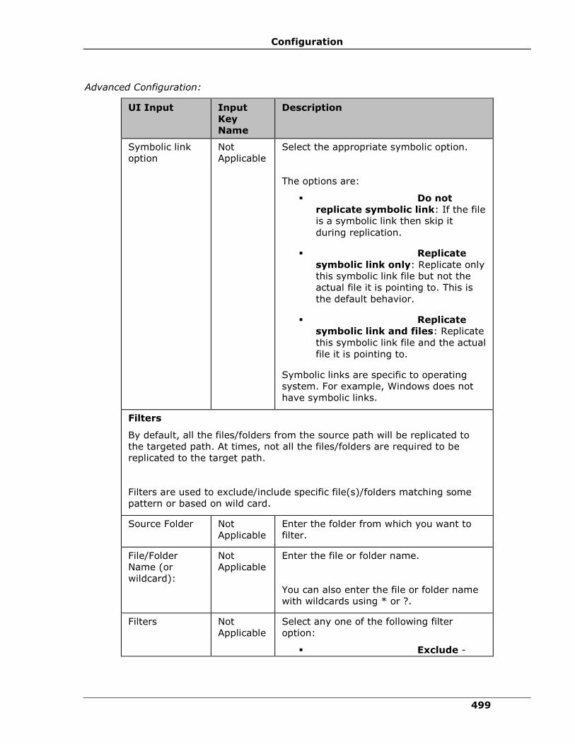
Configuration
499
Advanced Configuration:
UI Input Input
Key
Name
Description
Symbolic link
option
Not
Applicable
Select the appropriate symbolic option.
The options are:
▪ Do not
replicate symbolic link: If the file
is a symbolic link then skip it
during replication.
▪ Replicate
symbolic link only: Replicate only
this symbolic link file but not the
actual file it is pointing to. This is
the default behavior.
▪ Replicate
symbolic link and files: Replicate
this symbolic link file and the actual
file it is pointing to.
Symbolic links are specific to operating
system. For example, Windows does not
have symbolic links.
Filters
By default, all the files/folders from the source path will be replicated to
the targeted path. At times, not all the files/folders are required to be
replicated to the target path.
Filters are used to exclude/include specific file(s)/folders matching some
pattern or based on wild card.
Source Folder Not
Applicable
Enter the folder from which you want to
filter.
File/Folder
Name (or
wildcard):
Not
Applicable
Enter the file or folder name.
You can also enter the file or folder name
with wildcards using * or ?.
Filters Not
Applicable
Select any one of the following filter
option:
▪ Exclude -
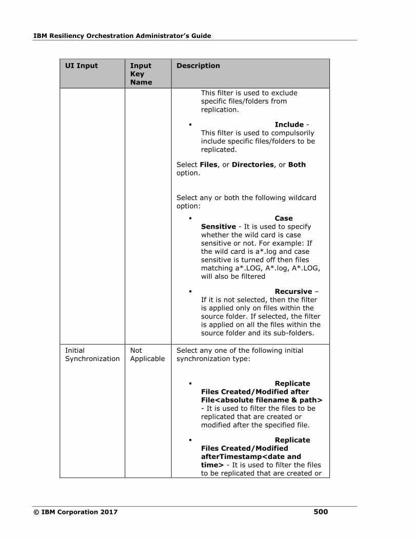
IBM Resiliency Orchestration Administrator’s Guide
© IBM Corporation 2017 500
UI Input Input
Key
Name
Description
This filter is used to exclude
specific files/folders from
replication.
▪ Include -
This filter is used to compulsorily
include specific files/folders to be
replicated.
Select Files, or Directories, or Both
option.
Select any or both the following wildcard
option:
▪ Case
Sensitive - It is used to specify
whether the wild card is case
sensitive or not. For example: If
the wild card is a*.log and case
sensitive is turned off then files
matching a*.LOG, A*.log, A*.LOG,
will also be filtered
▪ Recursive –
If it is not selected, then the filter
is applied only on files within the
source folder. If selected, the filter
is applied on all the files within the
source folder and its sub-folders.
Initial
Synchronization
Not
Applicable
Select any one of the following initial
synchronization type:
▪ Replicate
Files Created/Modified after
File<absolute filename & path>
- It is used to filter the files to be
replicated that are created or
modified after the specified file.
▪ Replicate
Files Created/Modified
afterTimestamp<date and
time> - It is used to filter the files
to be replicated that are created or

Configuration
501
UI Input Input
Key
Name
Description
modified after the specified date
and time.
▪ Avoid Full
Copy - It is used to replicate the
files that are created or modified
after the configuration of creating
fileset.
▪ None - No
initial synchronization, it replicate
all the files with the filtered
configuration.
This option is applicable only for CREATE
FILESET, and TRANSFER FILESET.
This option is not applicable for MODIFY
FILESET.
Sync delete
files
Automatically deletes files/folders on
target server when deleted on source
server. Note: The files/folders will be
deleted on target server only when it is
not part of exclusion list and fileset is
Enabled and PFR Service on target server
has sufficient privileges/permission for
deletion
Large File
Support
▪ Enable Large
File Support - Select this check box
to enable Large File Support for this
fileset.
▪ Size (MB) -
Enter the Large File Size value. The
default value is 1024 MB.
The Large File size cannot be less than the
bucket size. By default the Large File size
is set to 1024MB and bucket size to 100
MB.
If the user provides Large File size less
than bucket size, system will reset the
value to bucket size. For example, if Large
File size is set to say 5 MB, system will

IBM Resiliency Orchestration Administrator’s Guide
© IBM Corporation 2017 502
UI Input Input
Key
Name
Description
reset to bucket size.
Click Add.
Description:
This action creates the Fileset for replication.
Outputs:
The fileset will be created on the configured service/host.
Error Codes:
None.
Pre-checks
▪ Source and Target IPs are valid and reachable. Recorded as Error if not valid or reachable.
▪ Read/Write/Modify/Delete permissions to directories/files. Permission to Read on source and
Write/Modify/Delete on target. Recorded as Error otherwise.
▪ Availability of free disk space on source and target . Recorded as Warning if target is less
than source. Recorded as Error if target is less than 80 percent of source.
▪ DELETE FILESET
DELETE FILESET - Deletes the fileset.
Inputs:
Description:
This action deletes the fileset you have created earlier.
Outputs:
Deletes the existing fileset.
Error Codes:
None.
Pre-checks
▪ Locate fileset. Recorded as Warning if fileset is unavailable.
▪ Files are not pending for replication. Recorded as Warning if files are pending.
▪ Fileset is in disabled state. Recorded as Warning if fileset is not in disabled state.
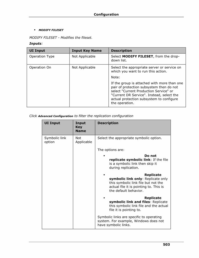
Configuration
503
▪ MODIFY FILESET
MODIFY FILESET - Modifies the fileset.
Inputs:
UI Input Input Key Name Description
Operation Type Not Applicable Select MODIFY FILESET, from the drop-
down list.
Operation On Not Applicable
Select the appropriate server or service on
which you want to run this action.
Note:
If the group is attached with more than one
pair of protection subsystem then do not
select "Current Production Service" or
"Current DR Service". Instead, select the
actual protection subsystem to configure
the operation.
Click Advanced Configuration to filter the replication configuration
UI Input Input
Key
Name
Description
Symbolic link
option
Not
Applicable
Select the appropriate symbolic option.
The options are:
▪ Do not
replicate symbolic link: If the file
is a symbolic link then skip it
during replication.
▪ Replicate
symbolic link only: Replicate only
this symbolic link file but not the
actual file it is pointing to. This is
the default behavior.
▪ Replicate
symbolic link and files: Replicate
this symbolic link file and the actual
file it is pointing to.
Symbolic links are specific to operating
system. For example, Windows does not
have symbolic links.

IBM Resiliency Orchestration Administrator’s Guide
© IBM Corporation 2017 504
UI Input Input
Key
Name
Description
Filters
By default, all the files/folders from the source path will be replicated to
the targeted path. At times, not all the files/folders are required to be
replicated to the target path.
Filters are used to exclude/include specific file(s)/folders matching some
pattern or based on wild card.
Source Folder Not
Applicable
Enter the folder from which you want to
filter.
File/Folder
Name (or
wildcard):
Not
Applicable
Enter the file or folder name.
You can also enter the file or folder name
with wildcards using * or ?.
Filters Not
Applicable
Select any one of the following filter
option:
▪ Exclude -
This filter is used to exclude
specific files/folders from
replication.
▪ Include -
This filter is used to compulsorily
include specific files/folders to be
replicated.
Select Files, or Directories, orBoth
option.
Select any or both the following wildcard
option:
▪ Case
Sensitive - It is used to specify
whether the wild card is case
sensitive or not. For example: If
the wild card is a*.log and case
sensitive is turned off then files
matching a*.LOG, A*.log, A*.LOG,
will also be filtered
▪ Recursive –
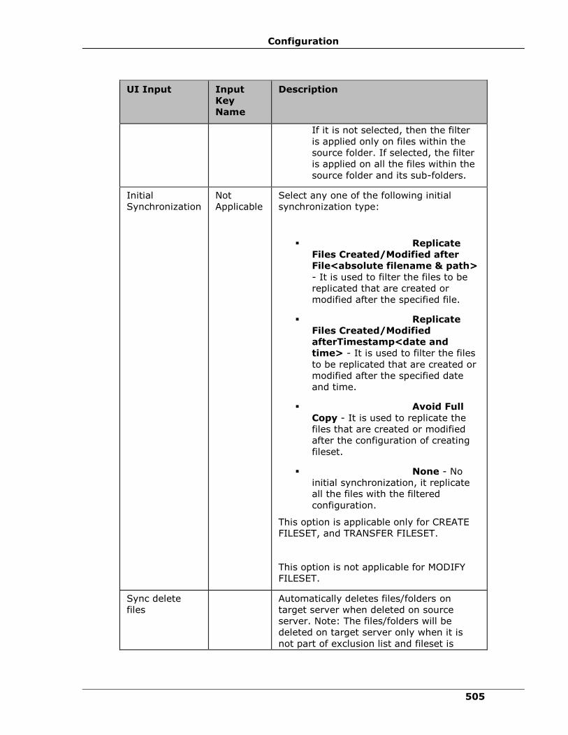
Configuration
505
UI Input Input
Key
Name
Description
If it is not selected, then the filter
is applied only on files within the
source folder. If selected, the filter
is applied on all the files within the
source folder and its sub-folders.
Initial
Synchronization
Not
Applicable
Select any one of the following initial
synchronization type:
▪ Replicate
Files Created/Modified after
File<absolute filename & path>
- It is used to filter the files to be
replicated that are created or
modified after the specified file.
▪ Replicate
Files Created/Modified
afterTimestamp<date and
time> - It is used to filter the files
to be replicated that are created or
modified after the specified date
and time.
▪ Avoid Full
Copy - It is used to replicate the
files that are created or modified
after the configuration of creating
fileset.
▪ None - No
initial synchronization, it replicate
all the files with the filtered
configuration.
This option is applicable only for CREATE
FILESET, and TRANSFER FILESET.
This option is not applicable for MODIFY
FILESET.
Sync delete
files
Automatically deletes files/folders on
target server when deleted on source
server. Note: The files/folders will be
deleted on target server only when it is
not part of exclusion list and fileset is

IBM Resiliency Orchestration Administrator’s Guide
© IBM Corporation 2017 506
UI Input Input
Key
Name
Description
Enabled and PFR Service on target server
has sufficient privileges/permission for
deletion
Large File
Support
▪ Enable Large
File Support - Select this check
box to enable Large File Support for this
fileset.
▪ Size(MB) -
Enter the Large File Size value. The
default value is 1024 MB.
The Large File size cannot be less
than the bucket size. By default
the Large File size is set to
1024MB and bucket size to 100
MB.
If the user provides Large File size
less than bucket size, system will
reset the value to bucket size. For
example, if Large File size is set to
say 5 MB, system will reset to
bucket size.
Description:
This action modifies the fileset configuration details.
Outputs:
Modifies the existing fileset.
Error Codes:
None.
Pre-checks
▪ Locate fileset. Recorded as Error (Warning in some cases) if fileset is unavailable.
▪ Source and Target IPs are valid and reachable. Recorded as Error if not valid or reachable.
▪ Files are not pending for replication. Recorded as Warning if files are pending.

Configuration
507
▪ Read/Write/Modify/Delete permissions to directories/files. Permission to Read on source
and Write/Modify/Delete on target. Recorded as Error otherwise.
▪ Availability of free disk space on source and target. Recorded as Warning if target is
less than source. Recorded as Error if target is less than 80 percent of source.
▪ STOP FILESET
STOP FILESET - Stops the fileset.
Inputs:
UI Input Input Key Name Description
Operation Type Not Applicable Select STOP FILESET, from
the drop-down list.
Operation On Not Applicable Select the appropriate server
or service on which you want
to run this action.
Note:
If the group is attached with
more than one pair of
protection subsystem then
do not select "Current
Production Service" or
"Current DR Service".
Instead, select the actual
protection subsystem to
configure the operation.
Description:
This action stops the ongoing replication of the specified fileset, if it is enabled.
Outputs:
Stops the replication of the fileset.
Error Codes:
None.
Pre-checks
▪ Fileset is valid. Recorded as Warning if fileset is not valid.
▪ Fileset is enabled. Recorded as Warning if fileset is not enabled.
▪ START FILESET
START FILESET - Starts the fileset.
Inputs:
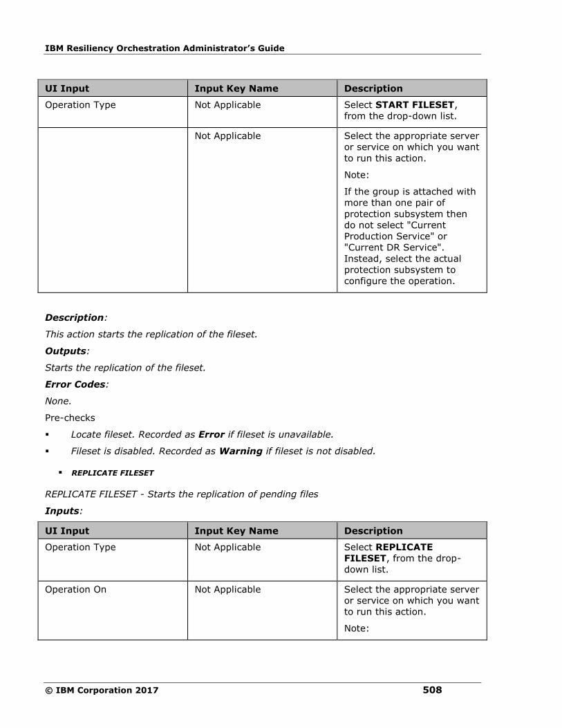
IBM Resiliency Orchestration Administrator’s Guide
© IBM Corporation 2017 508
UI Input Input Key Name Description
Operation Type Not Applicable Select START FILESET,
from the drop-down list.
Operation On Not Applicable Select the appropriate server
or service on which you want
to run this action.
Note:
If the group is attached with
more than one pair of
protection subsystem then
do not select "Current
Production Service" or
"Current DR Service".
Instead, select the actual
protection subsystem to
configure the operation.
Description:
This action starts the replication of the fileset.
Outputs:
Starts the replication of the fileset.
Error Codes:
None.
Pre-checks
▪ Locate fileset. Recorded as Error if fileset is unavailable.
▪ Fileset is disabled. Recorded as Warning if fileset is not disabled.
▪ REPLICATE FILESET
REPLICATE FILESET - Starts the replication of pending files
Inputs:
UI Input Input Key Name Description
Operation Type Not Applicable Select REPLICATE
FILESET, from the drop-
down list.
Operation On Not Applicable Select the appropriate server
or service on which you want
to run this action.
Note:
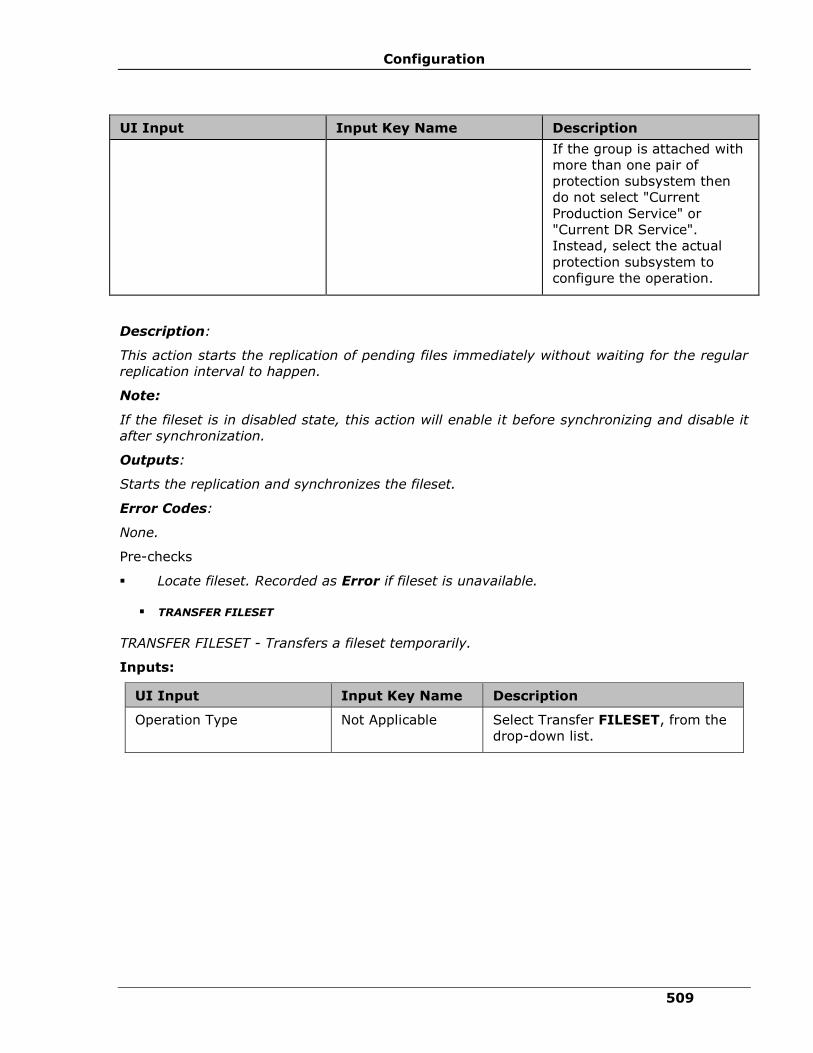
Configuration
509
UI Input Input Key Name Description
If the group is attached with
more than one pair of
protection subsystem then
do not select "Current
Production Service" or
"Current DR Service".
Instead, select the actual
protection subsystem to
configure the operation.
Description:
This action starts the replication of pending files immediately without waiting for the regular
replication interval to happen.
Note:
If the fileset is in disabled state, this action will enable it before synchronizing and disable it
after synchronization.
Outputs:
Starts the replication and synchronizes the fileset.
Error Codes:
None.
Pre-checks
▪ Locate fileset. Recorded as Error if fileset is unavailable.
▪ TRANSFER FILESET
TRANSFER FILESET - Transfers a fileset temporarily.
Inputs:
UI Input Input Key Name Description
Operation Type Not Applicable Select Transfer FILESET, from the
drop-down list.

IBM Resiliency Orchestration Administrator’s Guide
© IBM Corporation 2017 510
UI Input Input Key Name Description
Source Host
Not Applicable Select the appropriate host from
which you want to transfer the
fileset, from the
drop-down list.
Most of the time, this field is
dynamically filled by IBM Resiliency
Orchestration based
on the settings you have specified
at the time of Group creation.
These dynamic options are Current
Production Component and Current
DR Component.
Target Host Not Applicable Select the appropriate host to
which you want to transfer the
fileset, from the drop-down
list.
Most of the time, this field is
dynamically filled by IBM Resiliency
Orchestration based
on the settings you have specified
at the time of Group creation.
These dynamic options are Current
Production Component and Current
DR Component.
Source Dir/File
Not Applicable
Enter the directory or file from
which you want to transfer.
Target Dir/File Not Applicable
Enter the directory or file to which
you want to transfer the data.
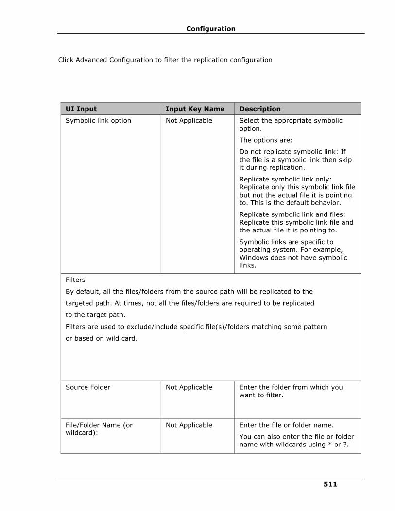
Configuration
511
Click Advanced Configuration to filter the replication configuration
UI Input Input Key Name Description
Symbolic link option
Not Applicable
Select the appropriate symbolic
option.
The options are:
Do not replicate symbolic link: If
the file is a symbolic link then skip
it during replication.
Replicate symbolic link only:
Replicate only this symbolic link file
but not the actual file it is pointing
to. This is the default behavior.
Replicate symbolic link and files:
Replicate this symbolic link file and
the actual file it is pointing to.
Symbolic links are specific to
operating system. For example,
Windows does not have symbolic
links.
Filters
By default, all the files/folders from the source path will be replicated to the
targeted path. At times, not all the files/folders are required to be replicated
to the target path.
Filters are used to exclude/include specific file(s)/folders matching some pattern
or based on wild card.
Source Folder
Not Applicable
Enter the folder from which you
want to filter.
File/Folder Name (or
wildcard):
Not Applicable
Enter the file or folder name.
You can also enter the file or folder
name with wildcards using * or ?.
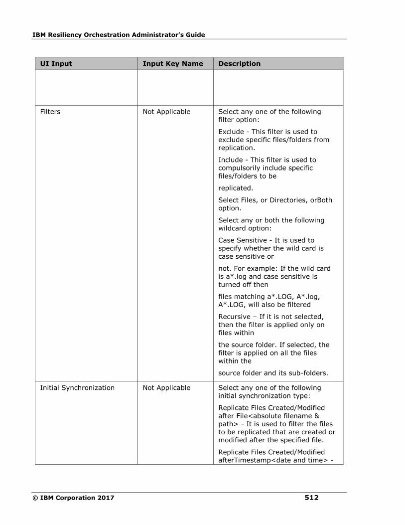
IBM Resiliency Orchestration Administrator’s Guide
© IBM Corporation 2017 512
UI Input Input Key Name Description
Filters
Not Applicable
Select any one of the following
filter option:
Exclude - This filter is used to
exclude specific files/folders from
replication.
Include - This filter is used to
compulsorily include specific
files/folders to be
replicated.
Select Files, or Directories, orBoth
option.
Select any or both the following
wildcard option:
Case Sensitive - It is used to
specify whether the wild card is
case sensitive or
not. For example: If the wild card
is a*.log and case sensitive is
turned off then
files matching a*.LOG, A*.log,
A*.LOG, will also be filtered
Recursive – If it is not selected,
then the filter is applied only on
files within
the source folder. If selected, the
filter is applied on all the files
within the
source folder and its sub-folders.
Initial Synchronization
Not Applicable
Select any one of the following
initial synchronization type:
Replicate Files Created/Modified
after File<absolute filename &
path> - It is used to filter the files
to be replicated that are created or
modified after the specified file.
Replicate Files Created/Modified
afterTimestamp<date and time> -

Configuration
513
UI Input Input Key Name Description
It is used to filter the files to be
replicated that are created or
modified after the specified date
and time.
Avoid Full Copy - It is used to
replicate the files that are created
or modified
after the configuration of creating
fileset.
None - No initial synchronization, it
replicate all the files with the
filtered configuration.
This option is applicable only for
CREATE FILESET, and TRANSFER
FILESET.
This option is not applicable for
MODIFY FILESET.
Sync delete files
Automatically deletes files/folders
on target server when deleted on
source server.
Note: The files/folders will be
deleted on target server only when
it is not part of exclusion list and
fileset is Enabled and PFR Service
on target server has sufficient
privileges/permission for deletion
Large File Support
Enable Large File Support - Select
this check box to enable Large File
Support for this fileset.
Size(MB) - Enter the Large File Size
value. The default value is 1024
MB.
The Large File size cannot be less
than the bucket size. By default the
Large File
size is set to 1024MB and bucket
size to 100 MB. If the user
provides Large File
size less than bucket size, system
will reset the value to bucket size.
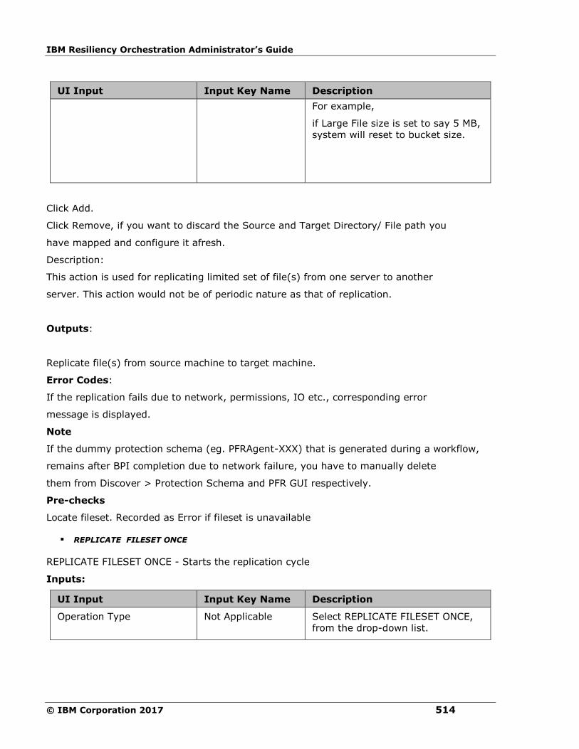
IBM Resiliency Orchestration Administrator’s Guide
© IBM Corporation 2017 514
UI Input Input Key Name Description
For example,
if Large File size is set to say 5 MB,
system will reset to bucket size.
Click Add.
Click Remove, if you want to discard the Source and Target Directory/ File path you
have mapped and configure it afresh.
Description:
This action is used for replicating limited set of file(s) from one server to another
server. This action would not be of periodic nature as that of replication.
Outputs:
Replicate file(s) from source machine to target machine.
Error Codes:
If the replication fails due to network, permissions, IO etc., corresponding error
message is displayed.
Note
If the dummy protection schema (eg. PFRAgent-XXX) that is generated during a workflow,
remains after BPI completion due to network failure, you have to manually delete
them from Discover > Protection Schema and PFR GUI respectively.
Pre-checks
Locate fileset. Recorded as Error if fileset is unavailable
▪ REPLICATE FILESET ONCE
REPLICATE FILESET ONCE - Starts the replication cycle
Inputs:
UI Input Input Key Name Description
Operation Type Not Applicable Select REPLICATE FILESET ONCE,
from the drop-down list.
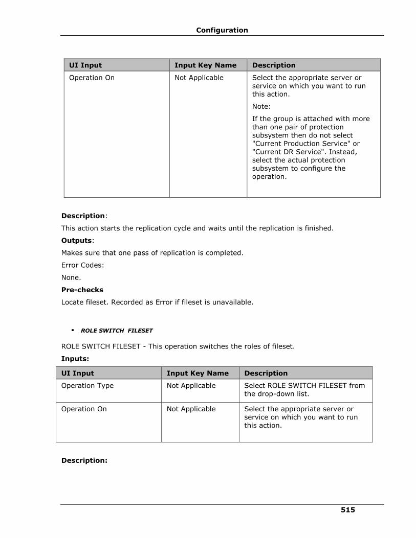
Configuration
515
UI Input Input Key Name Description
Operation On
Not Applicable
Select the appropriate server or
service on which you want to run
this action.
Note:
If the group is attached with more
than one pair of protection
subsystem then do not select
"Current Production Service" or
"Current DR Service". Instead,
select the actual protection
subsystem to configure the
operation.
Description:
This action starts the replication cycle and waits until the replication is finished.
Outputs:
Makes sure that one pass of replication is completed.
Error Codes:
None.
Pre-checks
Locate fileset. Recorded as Error if fileset is unavailable.
▪ ROLE SWITCH FILESET
ROLE SWITCH FILESET - This operation switches the roles of fileset.
Inputs:
UI Input Input Key Name Description
Operation Type Not Applicable Select ROLE SWITCH FILESET from
the drop-down list.
Operation On
Not Applicable
Select the appropriate server or
service on which you want to run
this action.
Description:

IBM Resiliency Orchestration Administrator’s Guide
© IBM Corporation 2017 516
This operation switches the roles of fileset. Before performing this operation, fileset should be
in the DISABLED state.
Outputs:
Switches the roles of fileset.
Pre-checks
Locate fileset. Recorded as Error if fileset is unavailable.
Fileset is valid. Record as Warning if fileset is not valid.
Fileset is disabled. Recorded as Warning if fileset is not disabled.
5. From the Operation On drop-down list, select the desired operation to be performed.
The Operation On drop-down list shows only the attached protection schemes by
default.
6. To view all the PFR protection schemes check Show All box. Clicking on Show All, all
the PFR protection schemes that are discovered on the “Server Components” that are
dependent on the dataset(s) of the group will be shown.
Note:
PFR Operation action does not take the directories from the datasets directly. You
need to specify the directories manually that you want protect. You must make sure
that you are specifying the right directories.
Unlike the concrete solution templates, generic solution based PFR Operation action
works on only one protection scheme at a time.
Replication
Choose Replication volume
Choose Replication Volume - Chooses Replication volume to operate on for further actions.
Description:
This action gets user a list of Replication Volume for the configured group. User can choose
one of the Replication Volume for further actions. This gives user flexibility during test
exercise or failover to choose Replication Volume that is more recent or consistent.
Configuration Options: Advanced properties provide following options.
▪ Choose at runtime

Configuration
517
When this is set at configuration time, action pops-up a user input window with a list of
Replication volume for user to choose one.
▪ Choose default RPO PIT Copy
Action will take the current RPO PIT Copy configured for the group.
▪ Choose default FO PIT Copy
Action will take the current FO PIT Copy configured for the group.
▪ List of discovered Replication volume that is included in the group
configuration
List shows all the available replication volume configured for the group. User can
choose one of it and it will be considered as chosen replication volume while action
executes.
Inputs:
UI Input Input Key Name Description
Option Type REPL_CHOOSE_RV_SVC_TYPE Select the replication
volume type from the drop-
down list.
The options are:
▪ ChooseAtRunTime
▪ DefaultRPOCopy
▪ DefaultFOCopy
▪ DiscoveredService
This field is mandatory.
RV Name REPL_CHOOSE_RV_OPER_ON Select the RV name from the
list.
If Option type is
‘DiscoveredService’, select
the name of Protection
service object.
This field is optional.
Outputs:

IBM Resiliency Orchestration Administrator’s Guide
© IBM Corporation 2017 518
Output
Name
Output Key Name Description
Protection
Service
name
PANREPL_CHOOSE_REPL_VOL_SERVICE_NAME Protection
Service
name of the
chosen
Replication
volume.
Replication
Volume
details
PANREPL_CHOOSE_REPL_VOL_DETAILS
Replication
Volume
details.
Volume
Group
Details
PANREPL_CHOOSE_VOL_DETAILS Volume
group
details like
mount point
information.
Error Codes:
None
IBM Internal (This is not for field use.)
Generate Raw Files
Not for field use.
Description
This action generates the RAW file from data file and offset file. It is used mainly in the
VMware solution.
Inputs
Input Key Name Input Type Optional/
Mandatory
COMPONENT_NAME Provide discovered component name Mandatory
COMPONENT_TYPE Provide component type Optional (By
default, STATIC)
DATA_PATH_LOCATION Absolute Data File directory location Mandatory
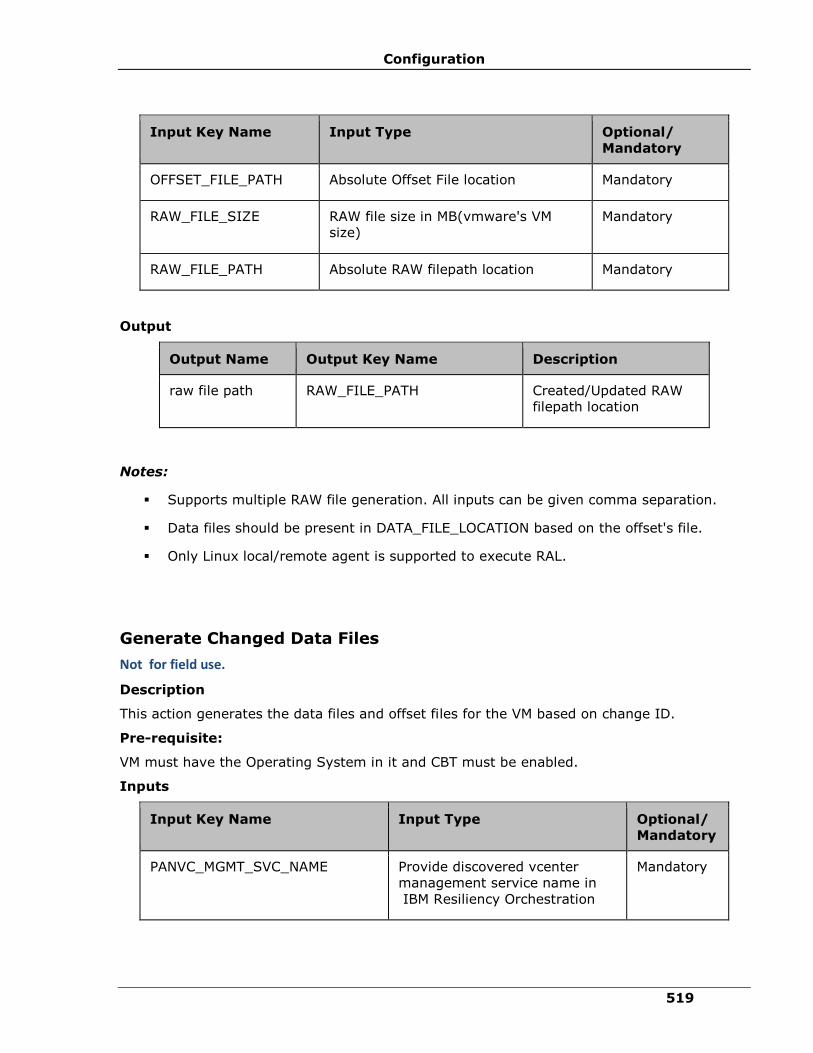
Configuration
519
Input Key Name Input Type Optional/
Mandatory
OFFSET_FILE_PATH Absolute Offset File location Mandatory
RAW_FILE_SIZE RAW file size in MB(vmware's VM
size)
Mandatory
RAW_FILE_PATH Absolute RAW filepath location Mandatory
Output
Output Name Output Key Name Description
raw file path RAW_FILE_PATH Created/Updated RAW
filepath location
Notes:
▪ Supports multiple RAW file generation. All inputs can be given comma separation.
▪ Data files should be present in DATA_FILE_LOCATION based on the offset's file.
▪ Only Linux local/remote agent is supported to execute RAL.
Generate Changed Data Files
Not for field use.
Description
This action generates the data files and offset files for the VM based on change ID.
Pre-requisite:
VM must have the Operating System in it and CBT must be enabled.
Inputs
Input Key Name Input Type Optional/
Mandatory
PANVC_MGMT_SVC_NAME Provide discovered vcenter
management service name in
IBM Resiliency Orchestration
Mandatory

IBM Resiliency Orchestration Administrator’s Guide
© IBM Corporation 2017 520
Input Key Name Input Type Optional/
Mandatory
PANVC_DC_NAME Provide datacenter name Mandatory
PANVC_VM_NAME Provide Virtual Machine name Mandatory
PANVC_VMDK_PATH Provide VM's VMDK path.
Multiple paths can be comma
separated
Mandatory
PANVC_VM_SNAPSHOT_ID Provide snapshot ID Mandatory
PANVC_REPLICATION_APPLIANCE Provide the discovered Linux
component name as replication
appliances where the CBT is
running.
Mandatory
PANVC_DATA_PATH Provide data/offset directory.
Eg: /opt/CBT. Data and offset
file are generated under
/opt/CBT/VMName/VMDKName.
Generated Offset file name will
be offset.txt
Mandatory
Output
Output
Name
Output Key Name Description
PANVC_CHNAGED_DATA_INFO [vmdkpath]:[changeid]:[data
output path]
OracleAppendEntriesTopfile
Not for field use.
Input:
Dataset Name should be given as the input which has to be updated in the pfile with DG
config.
▪ pfile name should <sidname>.ora
Result: Based on PR/DR machines the following configuration will be appended to the pfile.
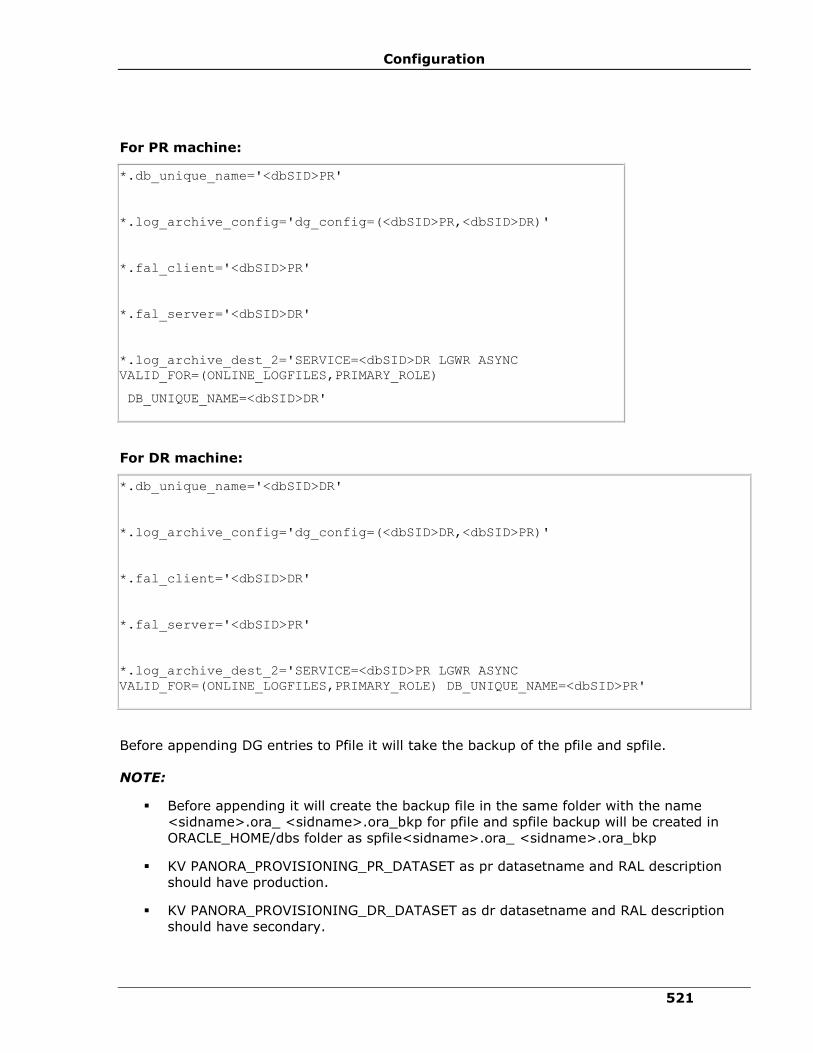
Configuration
521
For PR machine:
*.db_unique_name='<dbSID>PR'
*.log_archive_config='dg_config=(<dbSID>PR,<dbSID>DR)'
*.fal_client='<dbSID>PR'
*.fal_server='<dbSID>DR'
*.log_archive_dest_2='SERVICE=<dbSID>DR LGWR ASYNC
VALID_FOR=(ONLINE_LOGFILES,PRIMARY_ROLE)
DB_UNIQUE_NAME=<dbSID>DR'
For DR machine:
*.db_unique_name='<dbSID>DR'
*.log_archive_config='dg_config=(<dbSID>DR,<dbSID>PR)'
*.fal_client='<dbSID>DR'
*.fal_server='<dbSID>PR'
*.log_archive_dest_2='SERVICE=<dbSID>PR LGWR ASYNC
VALID_FOR=(ONLINE_LOGFILES,PRIMARY_ROLE) DB_UNIQUE_NAME=<dbSID>PR'
Before appending DG entries to Pfile it will take the backup of the pfile and spfile.
NOTE:
▪ Before appending it will create the backup file in the same folder with the name
<sidname>.ora_ <sidname>.ora_bkp for pfile and spfile backup will be created in
ORACLE_HOME/dbs folder as spfile<sidname>.ora_ <sidname>.ora_bkp
▪ KV PANORA_PROVISIONING_PR_DATASET as pr datasetname and RAL description
should have production.
▪ KV PANORA_PROVISIONING_DR_DATASET as dr datasetname and RAL description
should have secondary.
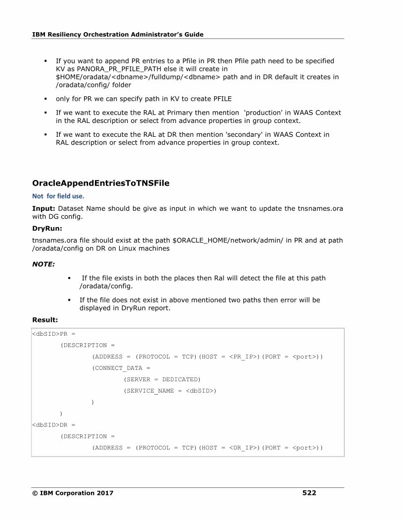
IBM Resiliency Orchestration Administrator’s Guide
© IBM Corporation 2017 522
▪ If you want to append PR entries to a Pfile in PR then Pfile path need to be specified
KV as PANORA_PR_PFILE_PATH else it will create in
$HOME/oradata/<dbname>/fulldump/<dbname> path and in DR default it creates in
/oradata/config/ folder
▪ only for PR we can specify path in KV to create PFILE
▪ If we want to execute the RAL at Primary then mention 'production' in WAAS Context
in the RAL description or select from advance properties in group context.
▪ If we want to execute the RAL at DR then mention 'secondary' in WAAS Context in
RAL description or select from advance properties in group context.
OracleAppendEntriesToTNSFile
Not for field use.
Input: Dataset Name should be give as input in which we want to update the tnsnames.ora
with DG config.
DryRun:
tnsnames.ora file should exist at the path $ORACLE_HOME/network/admin/ in PR and at path
/oradata/config on DR on Linux machines
NOTE:
▪ If the file exists in both the places then Ral will detect the file at this path
/oradata/config.
▪ If the file does not exist in above mentioned two paths then error will be
displayed in DryRun report.
Result:
<dbSID>PR =
(DESCRIPTION =
(ADDRESS = (PROTOCOL = TCP)(HOST = <PR_IP>)(PORT = <port>))
(CONNECT_DATA =
(SERVER = DEDICATED)
(SERVICE_NAME = <dbSID>)
)
)
<dbSID>DR =
(DESCRIPTION =
(ADDRESS = (PROTOCOL = TCP)(HOST = <DR_IP>)(PORT = <port>))
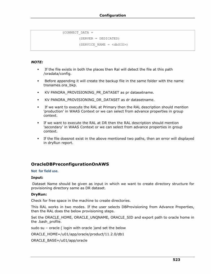
Configuration
523
(CONNECT_DATA =
(SERVER = DEDICATED)
(SERVICE_NAME = <dbSID>)
NOTE:
▪ If the file exists in both the places then Ral will detect the file at this path
/oradata/config.
▪ Before appending it will create the backup file in the same folder with the name
tnsnames.ora_bkp.
▪ KV PANORA_PROVISIONING_PR_DATASET as pr datasetname.
▪ KV PANORA_PROVISIONING_DR_DATASET as dr datasetname.
▪ If we want to execute the RAL at Primary then the RAL description should mention
'production' in WAAS Context or we can select from advance properties in group
context.
▪ If we want to execute the RAL at DR then the RAL description should mention
'secondary' in WAAS Context or we can select from advance properties in group
context.
▪ If the file doesnot exist in the above mentioned two paths, then an error will displayed
in dryRun report.
OracleDBPreconfigurationOnAWS
Not for field use.
Input:
Dataset Name should be given as input in which we want to create directory structure for
provisioning directory same as DR dataset.
DryRun:
Check for free space in the machine to create directories.
This RAL works in two modes. If the user selects DBProvisioning from Advance Properties,
then the RAL does the below provisioning steps.
Set the ORACLE_HOME, ORACLE_UNQNAME, ORACLE_SID and export path to oracle home in
the .bash_profile.
sudo su – oracle ( login with oracle )and set the below
ORACLE_HOME=/u01/app/oracle/product/11.2.0/db1
ORACLE_BASE=/u01/app/oracle

IBM Resiliency Orchestration Administrator’s Guide
© IBM Corporation 2017 524
ORACLE_SID=
PATH=$PATH:$ORACLE_HOME/bin/
export ORACLE_HOME ORACLE_SID ORACLE_BASE PATH
Assign privatekey to oracle user:
Create .ssh dir in the oracle user home and copy the authorized keys file from the ec2-user
home to the created directory and change the permission and give permission to oracle for
that file.
Chown oracle:oinstall .ssh/authorizedkeys
chmod 777 ssh/authorizedkeys
Create the directory structure in the attched volume (which is mounted on /oradata) as
shown below:
1.For the Archive log path and for taking fulldump
mkdir -p /oradata/< dbName >/fulldump/< dbName>/ archive
2. For the redo logfiles ctl files and db files
mkdir -p /oradata/< dbName >/data/< dbName >
3.For the all configuartion files like pwd , spfile, listener and tnsname files
mkdir -p /oradata/config
4. For the adump dpdump and pfile
mkdir -p /oradata/< dbName >/admin/< db_name >/adump
mkdir -p /oradata/< dbName >/admin/< db_name >/dpdump
mkdir -p /oradata/< dbName >/admin/< db_name >/pfile
Format the volume by below command
mkfs.ext4 /dev/xvdf
Mount the volume - mount /dev/xvdf /oradata
Give Oracle permission to the directory on which volume is mounted.
chown oracle:oinstall /oradata
If User selects SymbolicLink from Advance Properties, then RAL does below provisioning
steps. create softlinks as below:
Note:
create sofltlinks according to PR directory structure
1. For the dbf, ctl, redolog file

Configuration
525
ln -s /oradata/< dbName >/data $ORACLE_BASE/oradata
2. For the adump dpdump pfile
ln -s /oradata/< dbName >/admin/ $ORACLE_BASE/admin
3. For the archive and full dump
ln -s /oradata/< dbName >/fulldump/< dbName>/ /app/<db_name>(As In the PR )
4. For the configuration files(pwd,spfile,listner& tnsname.ora file)
a. a) ln -s /oradata/config/<pwd file name> / $ORACLE_HOME/dbs/<pwd file
name>
b. b) ln -s /oradata/config/<spfile name> /$ORACLE_HOME/dbs/< spfile name>
c. c) ln -s /oradata/config/<listener.ora> / $ORACLE_HOME/network/admin/<
listener.ora>
d. d) ln -s /oradata/config/<tnsname.ora>
$ORACLE_HOME/network/admin/<tnsnames.ora>
5. Path in which we have taken backup ctl and datafiles at PR
a) sudo ln -s /oradata/<dbname>/fulldump/<dbname> to
/home/oracle/oradata/<dbname>/fulldump/<dbname>(if KV for bkp is
not given)
b) sudo ln -s /oradata/<dbname>/fulldump/<dbname> to bkppath(if KV
for bkppath is given in kv)
KV
▪ PANORA_PROVISIONING_DR_DATASET as DR static dataset name
▪ PANORA_PROVISIONING_PR_DATASET as PR dataset name, as RAL needs to read PR
dataset ORACLE_HOME
▪ PANORA_EC2_ADVANCE_PROVISIONING as DBProvisioning or SymbolicLink.
▪ AWS_DEVICE as /dev/xvdf
OracleDBConfigFilesCreation
Not for field use.
CreateListenerFile RAL
Input:
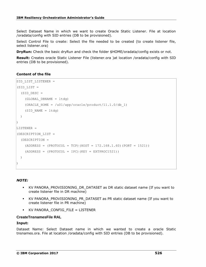
IBM Resiliency Orchestration Administrator’s Guide
© IBM Corporation 2017 526
Select Dataset Name in which we want to create Oracle Static Listener. File at location
/oradata/config with SID entries (DB to be provisioned).
Select Control File to create: Select the file needed to be created (to create listener file,
select listener.ora)
DryRun: Check the basic dryRun and check the folder $HOME/oradata/config exists or not.
Result: Creates oracle Static Listener File (listener.ora )at location /oradata/config with SID
entries (DB to be provisioned).
Content of the file
SID_LIST_LISTENER =
(SID_LIST =
(SID_DESC =
(GLOBAL_DBNAME = ltdg)
(ORACLE_HOME = /u01/app/oracle/product/11.1.0/db_1)
(SID_NAME = ltdg)
)
)
LISTENER =
(DESCRIPTION_LIST =
(DESCRIPTION =
(ADDRESS = (PROTOCOL = TCP)(HOST = 172.168.1.60)(PORT = 1521))
(ADDRESS = (PROTOCOL = IPC)(KEY = EXTPROC1521))
)
)
NOTE:
▪ KV PANORA_PROVISIONING_DR_DATASET as DR static dataset name (If you want to
create listener file in DR machine)
▪ KV PANORA_PROVISIONING_PR_DATASET as PR static dataset name (If you want to
create listener file in PR machine)
▪ KV PANORA_CONFIG_FILE = LISTENER
CreateTnsnamesFile RAL
Input:
Dataset Name: Select Dataset name in which we wanted to create a oracle Static
tnsnames.ora. File at location /oradata/config with SID entries (DB to be provisioned).

Configuration
527
Select Control File to create: Select the file needed to be created (for creating tnsnames.ora
file select tnsnames.ora). DB to be provisioned.
DryRun: Check the basic dryRun and check the folder /oradata/config exists or not.
Result: Creates oracle Static tnsnames.ora File at location /oradata/config with SID entries
(DB to be provisioned).
Content of the file
LTDG =
(DESCRIPTION =
(ADDRESS = (PROTOCOL = TCP)(HOST = 172.168.1.60)(PORT = 1522))
(CONNECT_DATA =
(SERVER = DEDICATED)
(SERVICE_NAME = ltdg)
)
)
NOTE:
▪ KV PANORA_CONFIG_FILE = TNSNAMES.
▪ KV PANORA_PROVISIONING_DR_DATASET as DR static dataset name (If you want to
create tnsnames file in DR machine).
▪ KV PANORA_PROVISIONING_PR_DATASET as PR static dataset name (If you want to
create tnsnames file in PR machine).
CreatePfileFile RAL
Input:
Dataset Name: Select Dataset Name in which you want to create a oracle Static PFile File at
location /oradata/config with SID entries (DB to be provisioned).
Select Control File to create: Select the file need to be created (for creating PFile file select
PFile) (DB to be provisioned).
DryRun: Check the basic DryRun and check the folder /oradata/config exists or not.
Result: Creates oracle Static PFile File at location /oradata/config with SID entries with
name <sid>Init_stdby.ora(DB to be provisioned).
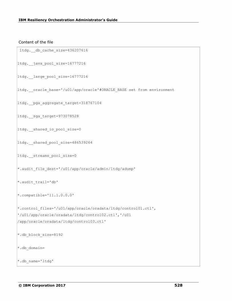
IBM Resiliency Orchestration Administrator’s Guide
© IBM Corporation 2017 528
Content of the file
ltdg.__db_cache_size=436207616
ltdg.__java_pool_size=16777216
ltdg.__large_pool_size=16777216
ltdg.__oracle_base='/u01/app/oracle'#ORACLE_BASE set from environment
ltdg.__pga_aggregate_target=318767104
ltdg.__sga_target=973078528
ltdg.__shared_io_pool_size=0
ltdg.__shared_pool_size=486539264
ltdg.__streams_pool_size=0
*.audit_file_dest='/u01/app/oracle/admin/ltdg/adump'
*.audit_trail='db'
*.compatible='11.1.0.0.0'
*.control_files='/u01/app/oracle/oradata/ltdg/control01.ctl',
'/u01/app/oracle/oradata/ltdg/control02.ctl','/u01
/app/oracle/oradata/ltdg/control03.ctl'
*.db_block_size=8192
*.db_domain=
*.db_name='ltdg'
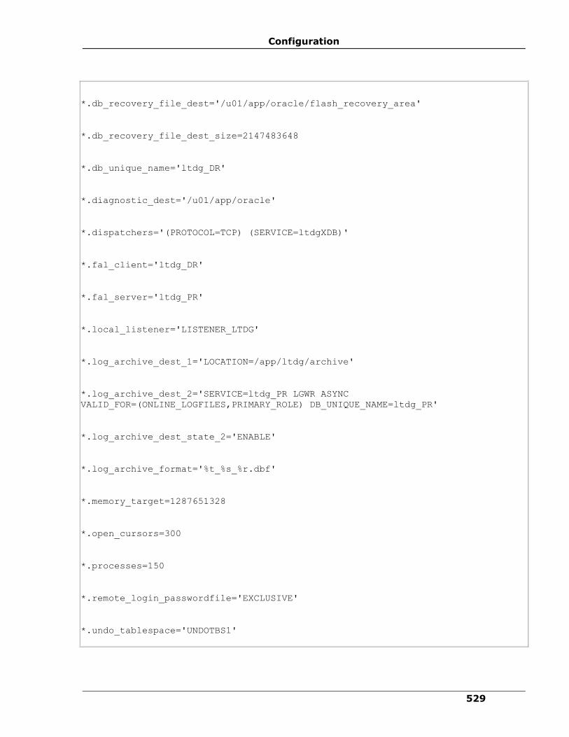
Configuration
529
*.db_recovery_file_dest='/u01/app/oracle/flash_recovery_area'
*.db_recovery_file_dest_size=2147483648
*.db_unique_name='ltdg_DR'
*.diagnostic_dest='/u01/app/oracle'
*.dispatchers='(PROTOCOL=TCP) (SERVICE=ltdgXDB)'
*.fal_client='ltdg_DR'
*.fal_server='ltdg_PR'
*.local_listener='LISTENER_LTDG'
*.log_archive_dest_1='LOCATION=/app/ltdg/archive'
*.log_archive_dest_2='SERVICE=ltdg_PR LGWR ASYNC
VALID_FOR=(ONLINE_LOGFILES,PRIMARY_ROLE) DB_UNIQUE_NAME=ltdg_PR'
*.log_archive_dest_state_2='ENABLE'
*.log_archive_format='%t_%s_%r.dbf'
*.memory_target=1287651328
*.open_cursors=300
*.processes=150
*.remote_login_passwordfile='EXCLUSIVE'
*.undo_tablespace='UNDOTBS1'
IBM Resiliency Orchestration Administrator’s Guide
© IBM Corporation 2017 530
NOTE:
▪ KV PANORA_CONFIG_FILE = PFILE.
▪ KV PANORA_PROVISIONING_DR_DATASET as DR static dataset name (If you want to
create pfile file in DR machine).
▪ KV PANORA_PROVISIONING_PR_DATASET as PR static dataset name (If you want to
create pfile file in PR machine).
▪ If you want to create a Pfile in PR then Pfile path need to be specified KV as
PANORA_PR_PFILE_PATH else it will create in
$HOME/oradata/<dbname>/fulldump/<dbname> path (path should have including
the pfilename eg:$HOME/oradata/<dbname>/fulldump/<dbname>/<SID.ora>)
▪ In DR, by default it creates in /oradata/config
OracleBackupDatabaseFileForAWS RAL
Not for field use.
Databasebackupfile RAL
Input:
Dataset Name should be give as input in which we want to take a backup of the database
and the database name.
DryRun: Check the database is available or not.
Result: Creates the backup file i.e. Data file at location /app/<SID_NAME>/
OPERATION:
Login rman target sys/password@instancename nocatalog msgno
backup database format =
'$HOME/oradata/"+oaco.SID+"/fulldump/"+oaco.SID+"/"+oaco.SID+"%d_%s_%t.data'
include current controlfile for standby;
NOTE:
▪ If KV is not given it will create the directory $HOME/oradata/<SID>/fulldump/<oaco>
and it creates the backup data files.
▪ If KV is provided then the file will be created in that path only.
▪ KV PANORA_BACKUP_DATABASE_FILE_PATH as path in which standby data file needs
to be created.

Configuration
531
▪ KV PANORA_PROVISIONING_PR_DATASET as PR static dataset name.
OracleCopyDBDataControlFileForAWS
Not for field use.
Input:
From Dataset Name and to Dataset Name should be give as input. (Works with SCP
Command).
DryRUN: Check the space to copy files.
Result: Copies all the data files, control files, pfile and password file to machine
copies the following files from one machine to another.
▪ datafile to the same location as on primary backup
e.g. /home/oracle/oradata/pocdg/fulldump/pocdg/*data to
[email protected]:/oradata/pocdg/fulldump/pocdg/ OR from backup path on
production to [email protected]:/oradata/pocdg/fulldump/pocdg/
(scp -i /tmp/oracleDGPOC.pem -o StrictHostKeyChecking=no -r
$HOME/oradata/pocdg/fulldump/pocdg/*
[email protected]:/oradata/pocdg/fulldump/pocdg/)
▪ controlfile to controlfile location of standby equal to number of control files on
primary.
e.g. /home/oracle/oradata/pocdg/fulldump/pocdg/*ctl to
[email protected]:/oradata/pocdg/fulldump/pocdg/
▪ spfile to $ORACLE_HOME/dbs folder on Unix.
e.g. /u01/app/oracle/product/11.2.0/db_1/dbs/spfilepocdg.ora to
[email protected]:/oradata/config/
▪ passwordfile to /oradata/config/ folder on Unix.
e.g. /u01/app/oracle/product/11.2.0/db_1/dbs/orapwpocdg to
[email protected]:/oradata/config/
▪ pfile to $ORACLE_HOME/dbs folder on unix.
e.g. /home/oracle/oradata/pocdg/fulldump/pocdg/*ora to
[email protected]:/oradata/config/
KV
▪ PANORA_PROVISIONING_PR_DATASET as PR static dataset name.
▪ PANORA_PROVISIONING_DR_DATASET as DR dataset name, as files to be copied to
DR EC2.
IBM Resiliency Orchestration Administrator’s Guide
© IBM Corporation 2017 532
OracleRestoreDatabaseFileForAWS
Not for field use.
RestoreDatabase RAL
Input:
Dataset Name should be give as input in which we want to restore database.
DryRun: Check the control file exists or not in the path.
Result: Restore datase.
OPERATION:
rman target sys/password@instancename nocatalog msgno
RMAN>restore controlfile from '<KVPATH>/<SID>_standby.ctl'; - if KV of the path is given,
this command gets executed.
RMAN>restore controlfile from
'$HOME/oradata/<SID>/fulldump/<SID>/<SID>_standby.ctl'; - if kv of the path is not given
then the command gets executed from directory /oradata/<SID>/fulldump/<SID>/
sqlplus "sys/password@instancename as sysdba"
alter database mount standby database;-mount databse in standby.
rman target sys/password@instancename nocatalog msgno
RMAN> RESTORE DATABASE; -Restores Databse.
NOTE:
▪ KV PANORA_RESTORE_CTL_FILE_PATH as the path of the control file to restore.
▪ KV PANORA_PROVISIONING_DR_DATASET as DR static dataset name.
▪ This Ral restores both control file and database file.
OracleRollbackProvisioningConfiguration
Not for field use.
This RAL has to fired on Production Dataset and this RAL will Delete/Revert the below content
of the file.
Configuration
533
1. Rollback of PFile : mv
$HOME/oradata/<dbname>/fulldump/<dbname>/<dbname>.ora_<dbname>_bkp
$HOME/oradata/<dbname>/fulldump/<dbname>/<dbname>.ora)
If Pfile is in (some other path specified throgh
wizard)<path>/<dbname>.ora_<dbname>_bkp <path>/<dbname>.ora
2. Rollback of SPFILE : mv $ORACLE_HOME/spfile<dbname>.ora_<dbname>_bkp
$ORACLE_HOME/spfile<dbname>.ora
3. Rollback of Tns file: (e.g. mv
/u01/app/oracle/product/11.2.0/db1/network/admin/tnsnames.ora_<dbname>_bkp
/u01/app/oracle/product/11.2.0/db1/network/admin/tnsnames.ora)
4. Data file and control file:
rm -rf $HOME/oradata/pocdg/fulldump/pocdg/*.data / rm -rf
/oradata/pocdg/fulldump/pocdg/*.ctl)
If Backup od data and control is in (some other path specified throgh wizard) rm -rf
<path>/*.data / rm -rf <path>/*.ctl)
NOTE:
▪ kv PANORA_PROVISIONING_PR_DATASET as PR static dataset name
OracleDBConfigFilesCreation-CreateSPfileFile
Not for field use.
Input:
Dataset Name: Should select Dataset Name. In which we want to create a Oracle Static
SPFile File at location /oradata/config with SID entries (DB to be provisioned).
Select Control File to create: Select the file that needs to be created (for creating SPFile file
select SPFile) (DB to be provisioned).
DryRun: Check the basic DryRun and check the folder /oradata/config exists or not.
Result: Creates Oracle Static SPFile File at location /oradata/config with SID entries with
name <sid>Init_stdby.ora(DB to be provisioned).
NOTE:
▪ KV PANORA_CONFIG_FILE = SPFILE
▪ KV PANORA_PROVISIONING_DR_DATASET as DR static dataset name (If you want to
create pfile file in DR machine)and description of RAL should have secondary.
▪ KV PANORA_PROVISIONING_PR_DATASET as PR static dataset name (If you want to
create pfile file in PR machine) and description of RAL should have production.
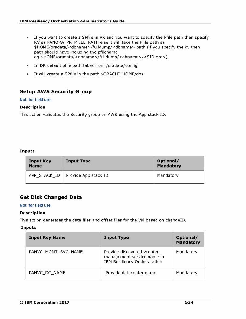
IBM Resiliency Orchestration Administrator’s Guide
© IBM Corporation 2017 534
▪ If you want to create a SPfile in PR and you want to specify the Pfile path then specify
KV as PANORA_PR_PFILE_PATH else it will take the Pfile path as
$HOME/oradata/<dbname>/fulldump/<dbname> path (if you specify the kv then
path should have including the pfilename
eg:$HOME/oradata/<dbname>/fulldump/<dbname>/<SID.ora>).
▪ In DR default pfile path takes from /oradata/config
▪ It will create a SPfile in the path $ORACLE_HOME/dbs
Setup AWS Security Group
Not for field use.
Description
This action validates the Security group on AWS using the App stack ID.
Inputs
Input Key
Name
Input Type Optional/
Mandatory
APP_STACK_ID Provide App stack ID Mandatory
Get Disk Changed Data
Not for field use.
Description
This action generates the data files and offset files for the VM based on changeID.
Inputs
Input Key Name Input Type Optional/
Mandatory
PANVC_MGMT_SVC_NAME Provide discovered vcenter
management service name in
IBM Resiliency Orchestration
Mandatory
PANVC_DC_NAME Provide datacenter name Mandatory
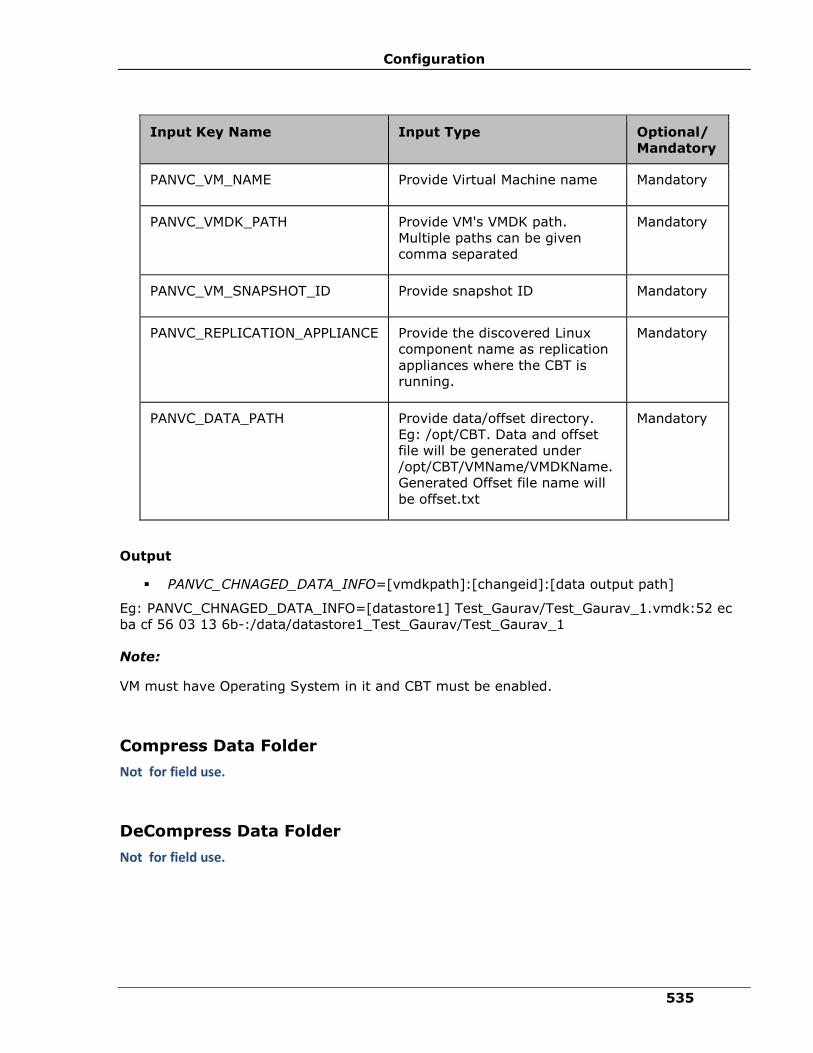
Configuration
535
Input Key Name Input Type Optional/
Mandatory
PANVC_VM_NAME Provide Virtual Machine name Mandatory
PANVC_VMDK_PATH Provide VM's VMDK path.
Multiple paths can be given
comma separated
Mandatory
PANVC_VM_SNAPSHOT_ID Provide snapshot ID Mandatory
PANVC_REPLICATION_APPLIANCE Provide the discovered Linux
component name as replication
appliances where the CBT is
running.
Mandatory
PANVC_DATA_PATH Provide data/offset directory.
Eg: /opt/CBT. Data and offset
file will be generated under
/opt/CBT/VMName/VMDKName.
Generated Offset file name will
be offset.txt
Mandatory
Output
▪ PANVC_CHNAGED_DATA_INFO=[vmdkpath]:[changeid]:[data output path]
Eg: PANVC_CHNAGED_DATA_INFO=[datastore1] Test_Gaurav/Test_Gaurav_1.vmdk:52 ec
ba cf 56 03 13 6b-:/data/datastore1_Test_Gaurav/Test_Gaurav_1
Note:
VM must have Operating System in it and CBT must be enabled.
Compress Data Folder
Not for field use.
DeCompress Data Folder
Not for field use.

IBM Resiliency Orchestration Administrator’s Guide
© IBM Corporation 2017 536
SetupAWSNetwork
Not for field use.
Workflow
Assignment Operation
Assign - Assigns the value of one key to another key.
Description:
This action supports assigning multiple parameters. This action can be used to assign the
value of a user defined parameter/ system generated parameter to another parameter. This
will assign the value of the right operand to the left operand only once. Further change in the
value of the right operand is not reflected in the left operand.
Both the participants (left operand and right operand) of the assignments should be
parameters. Literals and constants are not permissible.
Any number of operands-pairs can be added to a list of Added Expressions.
Note:
On executing the Dry Run for this operation, the Assignment Operation action is also
executed.
Inputs:
UI Input Input Key Name Description
Parameter
Name of Left
Operand in
assignment
PANSVR_EXPR_LEFT_OPERAND Enter the key name of the left operand
in assignment.
This field is mandatory.
Parameter
Name of
Right
Operand in
assignment
PANSVR_EXPR_RIGHT_OPERAND Enter the key name of the right
operand in assignment.
This field is mandatory.
Parameter
Name of the
Added
Expressions
in assignment
PANSVR_EXPR_OPERAND Adds the assigned keys
PANSVR_EXPR_LEFT_OPERAND and
PANSVR_EXPR_RIGHT_OPERAND into
a list.

Configuration
537
Outputs:
Assignment Operation returns a String value that contains the old value and new value of all
the Left operands in the Added Expressions’ list.
Error Codes:
None
Pre-checks
▪ Left operand input is provided.
▪ Right operand input is provided.
▪ Left and Right operand inputs are provided using Key Values.
▪ Left and Right operand inputs have no space.
Compare Operation
Compare - Compares the value of one key with another key.
Description
This action can be used to compare user defined/system generated parameters. This
compares the value of the right operand with the left operand.
Both the participants (left operand and right operand) in comparison should be parameters.
Literals and constants are not permissible.
Left operand and right operand can contain a string, an integer, or a date. Default value is
'string'. They must have the same data type.
Logical operations of '==' (EQUALS), '!='(NOT EQUALS), '<' (LESS THAN), '<=' (LESS THAN
OR EQUALS), '>' (GREATER THAN) and '>=' (GREATER THAN OR EQUALS) are supported.
Inputs:
UI Input Input Key Name Description
Parameter
Name of Left
Operand in
comparison
PANSVR_EXPR_LEFT_OPERAND Enter the key name of
the left operand in
assignment.
This field is mandatory.

IBM Resiliency Orchestration Administrator’s Guide
© IBM Corporation 2017 538
UI Input Input Key Name Description
Parameter
Name of Right
Operand in
comparison
PANSVR_EXPR_RIGHT_OPERAND Enter the key name of
the right operand in
assignment.
This field is mandatory.
Operator PANSVR_EXPR_OPERAND Select the operator
from the drop-down
list.
Available operators
are: ==,!=,<,<=,>,>
.
This field is mandatory.
Datatype PANSVR_EXPR_DATATYPE Select the data type
from the drop-down
list.
Available data types
are: string, int and
date.
This field is optional.
Outputs:
Output Name Output Key Name Description
Parameter
Name of Left
Operand in
assignment
PANSVR_EXPR_LEFT_OPERAND The output of this action
will be a boolean value -
'true' or 'false' based.
Error Codes:
None
Note:
Configuration
539
▪ XML/HTML/URL uses '<' and '>' as part of specifications and it has to be mapped to
'<' and '>' respectively.
▪ Logical expression evaluating to 'FALSE' will set the action result as 'FAILURE'.
▪ The date should be in MM-dd-yyyy HH:mm:ss format.
Pre-checks
▪ Left operand input is provided.
▪ Right operand input is provided.
▪ Left and Right operand inputs are provided using Key Values.
▪ Operator is selected.
▪ Datatype is selected.
▪ Left and Right operand inputs have no space.
Custom Action
Custom - Executes the command or script on the specified server.
Description:
This action allows you configure a command or script (scripts like TCL/ Shell) to be executed
on a specified server. If you select TCL, IBM Resiliency Orchestration will internally take care
of the TCL environment to run the TCL script.
Inputs:
To enter the Inputs in the Customs page:
1 From Workflow Editor, double click the Custom Action. A Custom page appears.
2 Select the Action properties tab, and enter the contents as mentioned in the table below.
UI Input Input Key Name Description

IBM Resiliency Orchestration Administrator’s Guide
© IBM Corporation 2017 540
UI Input Input Key Name Description
Server/ Machine Name
CUSTOM_ACTION_COMPONENT
_NAME
CUSTOM_ACTION_COMPONENT
_TYPE
Select server (or) machine from the drop-down list box.
OR
Add the following in the Key Value pairs.
▪ If CUSTOM_ACTION_COMPONENT_TYPE is DYNAMIC then CUSTOM_ACTION_COMPONENT_NAME should be either Production Server or DR Server
▪ If CUSTOM_ACTION_COMPONENT_TYPE is STATIC then CUSTOM_ACTION_COMPONENT_NAME should be any discovered component name.
Note:
You can execute command/ script on your configured Primary or Remote server. If you always need to execute command/ script on your current Production Server select Production Server. Select DR Server, if you need your command/ script to execute always on your current DR server.
Type of Custom Action
Not Applicable Select the type of custom action you want to configure.
▪ Command
▪ Script
▪ IBM Resiliency Orchestration Integration TCL script - If selected component/ server is remotely managed, this script runs on Agent node.
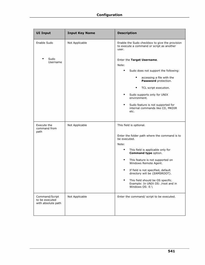
Configuration
541
UI Input Input Key Name Description
Enable Sudo
▪ Sudo Username
Not Applicable Enable the Sudo checkbox to give the provision to execute a command or script as another user.
Enter the Target Username.
Note:
▪ Sudo does not support the following:
▪ accessing a file with the Password protection.
▪ TCL script execution.
▪ Sudo supports only for UNIX environment.
▪ Sudo feature is not supported for internal commands like CD, MKDIR etc.
Execute the command from path
Not Applicable This field is optional.
Enter the folder path where the command is to be executed.
Note:
▪ This field is applicable only for Command type option.
▪ This feature is not supported on Windows Remote Agent.
▪ If field is not specified, default directory will be {EAMSROOT}.
▪ This field should be OS specific. Example: In UNIX OS: /root and in Windows OS: E:\
Command/Script to be executed with absolute path
Not Applicable Enter the command/ script to be executed.

IBM Resiliency Orchestration Administrator’s Guide
© IBM Corporation 2017 542
UI Input Input Key Name Description
View Script Not Applicable
On selection of Script option in the Custom type field, this button is available. Click this button to view the contents of the scripts which is entered in Command/ Script to be executed with absolute path field.
Log file path for custom script
Not Applicable Enter the log file path.
The User can provide the absolute path of the log file generated from custom scripts, system logs or event logs. The same log file can be tailed using tail log link in Workflow Recent Execution page.
Note:
▪ To use Tail log functionality, TAIL library must be installed in Unix/ Windows OS.
▪ Tail log feature of custom RAL will work only if component is selected from Action properties and not through KV pair.
Server where Command/ script should be located
Not Applicable
The value is fetched by the system automatically, which shows the name of the server/ component where script is located.
Timeout (Sec) Not Applicable
Enter the execution wait time in seconds.
The value '0' in this field defines indefinite wait. This is true for both Dry run and Actual execution.
Enable Dry Run
▪ Dry run execution type
▪ Dry run command path
Not Applicable Select the Dry run option to pre-check the connectivity, privileges and absolute path before the actual execution.
Click on any one option: Script or IBM Resiliency Orchestration integration TCL
script
Enter the path to run the script.
Outputs:
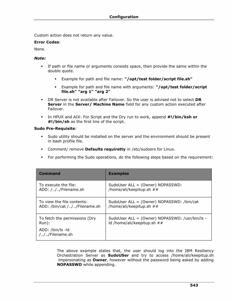
Configuration
543
Custom action does not return any value.
Error Codes:
None.
Note:
▪ If path or file name or arguments consists space, then provide the same within the
double quote.
▪ Example for path and file name: "/opt/test folder/script file.sh"
▪ Example for path and file name with arguments: "/opt/test folder/script
file.sh" "arg 1" "arg 2"
▪ DR Server is not available after Failover. So the user is advised not to select DR
Server in the Server/ Machine Name field for any custom action executed after
Failover.
▪ In HPUX and AIX: For Script and the Dry run to work, append #!/bin/ksh or
#!/bin/sh as the first line of the script.
Sudo Pre-Requisite:
▪ Sudo utility should be installed on the server and the environment should be present
in bash profile file.
▪ Comment/ remove Defaults requiretty in /etc/sudoers for Linux.
▪ For performing the Sudo operations, do the following steps based on the requirement:
Command Examples
To execute the file:
ADD: /../../Filename.sh
SudoUser ALL = (Owner) NOPASSWD:
/home/ali/keepitup.sh ##
To view the file contents:
ADD: /bin/cat /../../Filename.sh
SudoUser ALL = (Owner) NOPASSWD: /bin/cat
/home/ali/keepitup.sh ##
To fetch the permissions (Dry
Run):
ADD: /bin/ls -ld
/../../Filename.sh
SudoUser ALL = (Owner) NOPASSWD: /usr/bin/ls -
ld /home/ali/keepitup.sh ##
The above example states that, the user should log into the IBM Resiliency
Orchestration Server as SudoUSer and try to access /home/ali/keepitup.sh
impersonating as Owner, however without the password being asked by adding
NOPASSWD while appending.
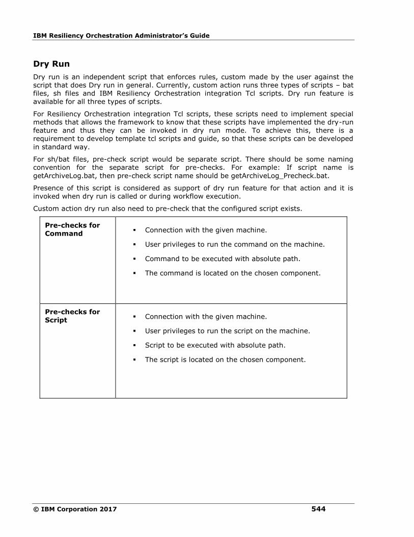
IBM Resiliency Orchestration Administrator’s Guide
© IBM Corporation 2017 544
Dry Run
Dry run is an independent script that enforces rules, custom made by the user against the
script that does Dry run in general. Currently, custom action runs three types of scripts – bat
files, sh files and IBM Resiliency Orchestration integration Tcl scripts. Dry run feature is
available for all three types of scripts.
For Resiliency Orchestration integration Tcl scripts, these scripts need to implement special
methods that allows the framework to know that these scripts have implemented the dry-run
feature and thus they can be invoked in dry run mode. To achieve this, there is a
requirement to develop template tcl scripts and guide, so that these scripts can be developed
in standard way.
For sh/bat files, pre-check script would be separate script. There should be some naming
convention for the separate script for pre-checks. For example: If script name is
getArchiveLog.bat, then pre-check script name should be getArchiveLog_Precheck.bat.
Presence of this script is considered as support of dry run feature for that action and it is
invoked when dry run is called or during workflow execution.
Custom action dry run also need to pre-check that the configured script exists.
Pre-checks for
Command ▪ Connection with the given machine.
▪ User privileges to run the command on the machine.
▪ Command to be executed with absolute path.
▪ The command is located on the chosen component.
Pre-checks for
Script ▪ Connection with the given machine.
▪ User privileges to run the script on the machine.
▪ Script to be executed with absolute path.
▪ The script is located on the chosen component.
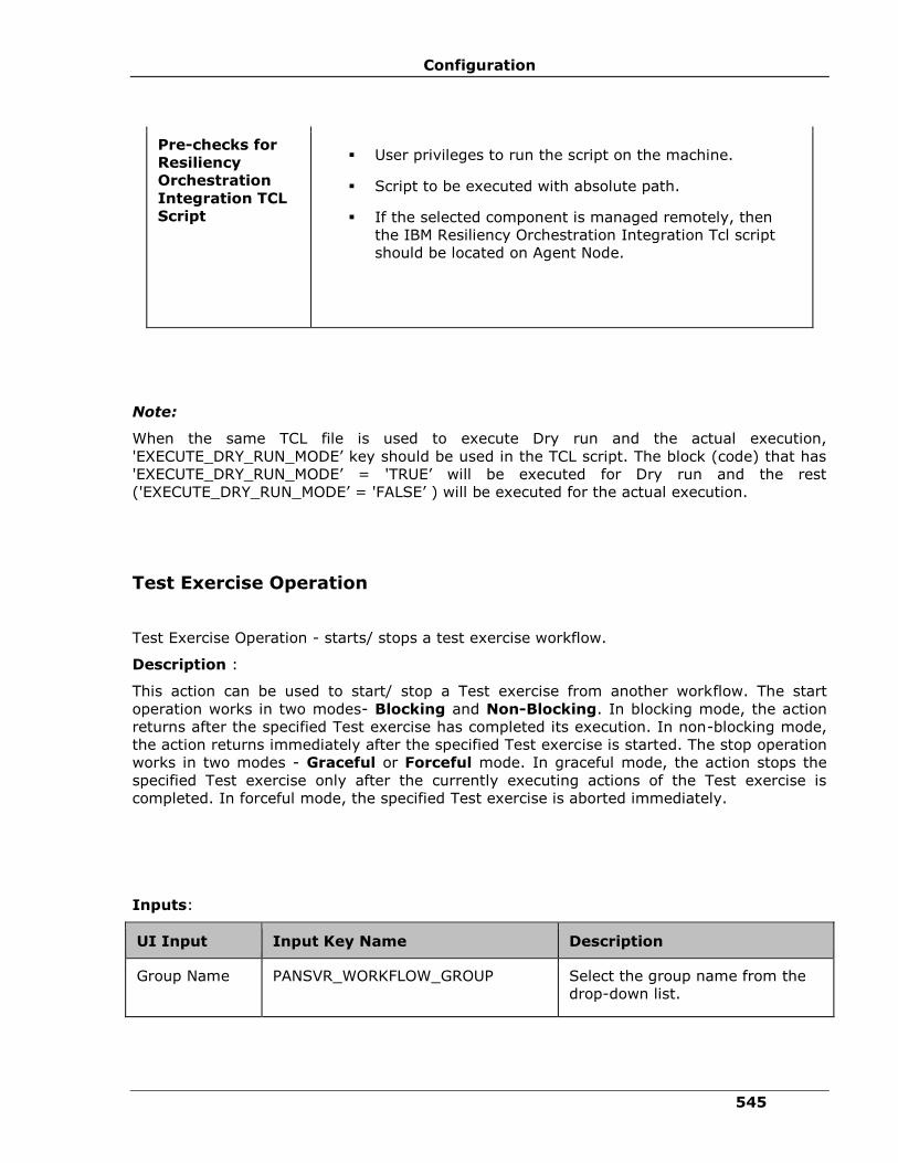
Configuration
545
Pre-checks for
Resiliency
Orchestration
Integration TCL
Script
▪ User privileges to run the script on the machine.
▪ Script to be executed with absolute path.
▪ If the selected component is managed remotely, then
the IBM Resiliency Orchestration Integration Tcl script
should be located on Agent Node.
Note:
When the same TCL file is used to execute Dry run and the actual execution,
'EXECUTE_DRY_RUN_MODE’ key should be used in the TCL script. The block (code) that has
'EXECUTE_DRY_RUN_MODE’ = 'TRUE’ will be executed for Dry run and the rest
('EXECUTE_DRY_RUN_MODE’ = 'FALSE’ ) will be executed for the actual execution.
Test Exercise Operation
Test Exercise Operation - starts/ stops a test exercise workflow.
Description :
This action can be used to start/ stop a Test exercise from another workflow. The start
operation works in two modes- Blocking and Non-Blocking. In blocking mode, the action
returns after the specified Test exercise has completed its execution. In non-blocking mode,
the action returns immediately after the specified Test exercise is started. The stop operation
works in two modes - Graceful or Forceful mode. In graceful mode, the action stops the
specified Test exercise only after the currently executing actions of the Test exercise is
completed. In forceful mode, the specified Test exercise is aborted immediately.
Inputs:
UI Input Input Key Name Description
Group Name PANSVR_WORKFLOW_GROUP Select the group name from the
drop-down list.
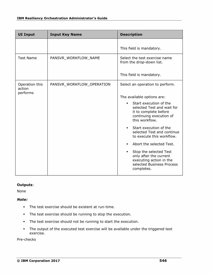
IBM Resiliency Orchestration Administrator’s Guide
© IBM Corporation 2017 546
UI Input Input Key Name Description
This field is mandatory.
Test Name PANSVR_WORKFLOW_NAME Select the test exercise name
from the drop-down list.
This field is mandatory.
Operation this
action
performs
PANSVR_WORKFLOW_OPERATION Select an operation to perform.
The available options are:
▪ Start execution of the
selected Test and wait for
it to complete before
continuing execution of
this workflow.
▪ Start execution of the
selected Test and continue
to execute this workflow.
▪ Abort the selected Test.
▪ Stop the selected Test
only after the current
executing action in the
selected Business Process
completes.
Outputs:
None
Note:
▪ The test exercise should be existent at run-time.
▪ The test exercise should be running to stop the execution.
▪ The test exercise should not be running to start the execution.
▪ The output of the executed test exercise will be available under the triggered test
exercise.
Pre-checks

Configuration
547
▪ The test exercise is available at run-time.
▪ The test exercise is running to stop the execution.
▪ The test exercise is not running to start the execution.
BPI Operation
BPI Operation - starts/ stops a BPI workflow.
Description:
This action can be used to start/stop a BPI workflow from another
workflow. The start operation works in two modes - Blocking and Non-
Blocking. In blocking mode, the action returns after the specified BPI
workflow has completed its execution. In non-blocking mode, the action
returns immediately after the specified BPI is started. The stop operation
works in two modes - Graceful or Forceful mode. In graceful mode, the
action stops the specified BPI only after the currently executing actions of
the BPI is completed. In forceful mode, the specified BPI is aborted
immediately.
Inputs:
UI Input Input Key Name Description
Group Name PANSVR_WORKFLOW_
GROUP
Select the group name from the
drop-down list.
This field is mandatory.
Business Process
Name
PANSVR_WORKFLOW_
NAME
Select an business process name
from the drop-down list.
This field is mandatory.
Operation this
action performs
PANSVR_WORKFLOW_
OPERATION
Select an operation to perform.
The available options are:
▪ Start execution of the
selected Business Process
and wait for it to
complete before

IBM Resiliency Orchestration Administrator’s Guide
© IBM Corporation 2017 548
UI Input Input Key Name Description
continuing execution of
this workflow.
▪ Start execution of the
selected Business Process
and continue to execute
this workflow.
▪ Abort the selected
Business Process.
▪ Stop the selected
Business Process only
after the current
executing action in the
selected Business Process
completes.
Outputs:
None
Note
▪ The BPI workflow should be existent at run-time.
▪ The workflow should be running to stop the execution.
▪ The workflow should not be running to start the execution.
▪ The output of the executed BPI will be available under the triggered BPI workflow.
Pre-checks
▪ A group should exist.
▪ BPI workflow is available for BPI operation.
▪ BPI workflow is running to perform stop operation.
▪ BPI workflow is not running to start the execution.
▪ File/Folders has sufficient permissions to execute the BPI.
Find Pattern

Configuration
549
Fine Pattern - Checks whether a particular pattern is available in the specified string.
Description:
This action checks whether a particular pattern is available in the specified string. This can be
used to parse the output of the execution of a command/script and verify whether the
command/script started the application successfully or not.
Inputs:
UI Input Input Key Name Description
Component
Name Not Applicable Select the
component from the
drop-down list.
Pattern to
search PANOS_SEARCH_PATTERN Enter the pattern to
search in the
content.
This field is
mandatory.
Content PANOS_SEARCH_CONTENT Enter the path to
content where you
want to search for
the pattern.
This field is
mandatory.
Outputs:
Output
Name
Output Key Name Description
Pattern
Found
PANOS_SEARCH_CONTENT_RESULT The output of
this action will
be a boolean
value - 'true'
or 'false'
based.
True if the
pattern is
found, else

IBM Resiliency Orchestration Administrator’s Guide
© IBM Corporation 2017 550
Output
Name
Output Key Name Description
false
Error Codes:
Error Code Description
PAN-CGEN-0002 Invalid component
name.
Pre-checks
▪ Values are configured.
Group Lock
Group Lock - Creates lock on Group.
Description:
This action creates lock on Group. If one group wants to lock to perform certain actions, first
the group acquires a lock. After completing the actions, the group releases the lock.
Inputs:
UI Input Input Key Name Description
Dont use lock Not Applicable Select this option if you do not want
to use the lock.
This field is mandatory.
Acquire lock Not Applicable Select this option to acquire a lock.
This field is mandatory.
Release lock Not Applicable Select this option to release the lock.
This field is mandatory.
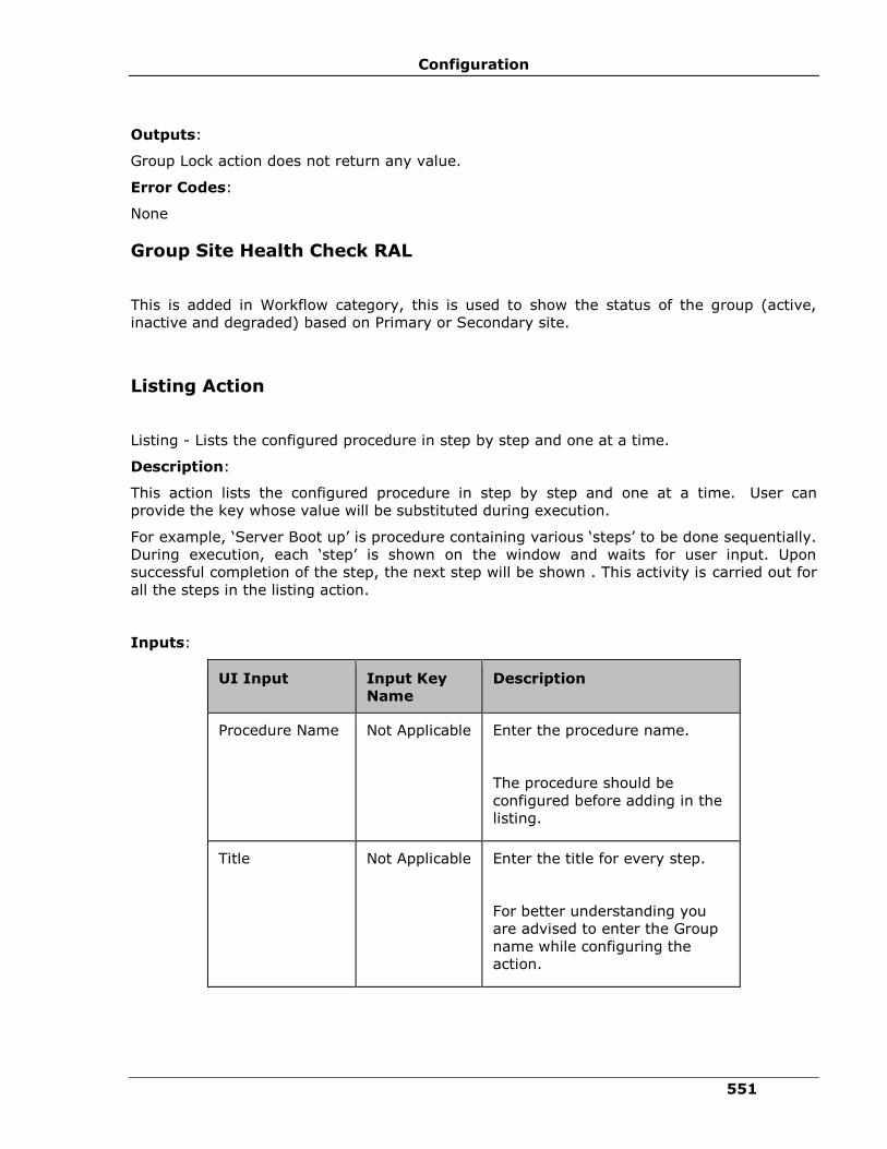
Configuration
551
Outputs:
Group Lock action does not return any value.
Error Codes:
None
Group Site Health Check RAL
This is added in Workflow category, this is used to show the status of the group (active,
inactive and degraded) based on Primary or Secondary site.
Listing Action
Listing - Lists the configured procedure in step by step and one at a time.
Description:
This action lists the configured procedure in step by step and one at a time. User can
provide the key whose value will be substituted during execution.
For example, ‘Server Boot up’ is procedure containing various ‘steps’ to be done sequentially.
During execution, each ‘step’ is shown on the window and waits for user input. Upon
successful completion of the step, the next step will be shown . This activity is carried out for
all the steps in the listing action.
Inputs:
UI Input Input Key
Name
Description
Procedure Name Not Applicable Enter the procedure name.
The procedure should be
configured before adding in the
listing.
Title Not Applicable Enter the title for every step.
For better understanding you
are advised to enter the Group
name while configuring the
action.
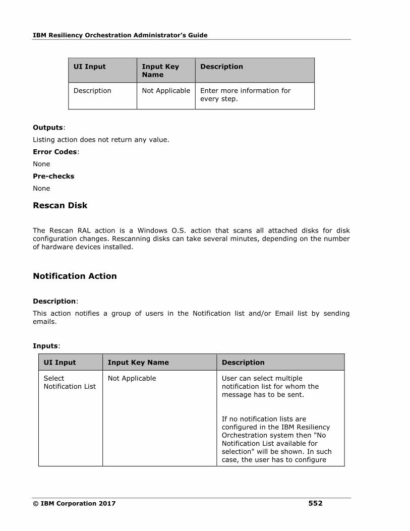
IBM Resiliency Orchestration Administrator’s Guide
© IBM Corporation 2017 552
UI Input Input Key
Name
Description
Description Not Applicable Enter more information for
every step.
Outputs:
Listing action does not return any value.
Error Codes:
None
Pre-checks
None
Rescan Disk
The Rescan RAL action is a Windows O.S. action that scans all attached disks for disk
configuration changes. Rescanning disks can take several minutes, depending on the number
of hardware devices installed.
Notification Action
Description:
This action notifies a group of users in the Notification list and/or Email list by sending
emails.
Inputs:
UI Input Input Key Name Description
Select
Notification List
Not Applicable User can select multiple
notification list for whom the
message has to be sent.
If no notification lists are
configured in the IBM Resiliency
Orchestration system then "No
Notification List available for
selection" will be shown. In such
case, the user has to configure

Configuration
553
UI Input Input Key Name Description
"Send Email to" to whom the
message has to be sent.
Send Email to PANSRV_NOTIFY_EMAIL_IDS Enter the email address of the
notification recipient.
Max. of 2048 chars are allowed.
The user cannot type beyond
2048 chars.
You can provide multiple email-ids
separated by comma. The email-
ids should be in the form of
To receive notifications as SMS,
specify Mobile Email Id in the
Email field. It is recommended to
keep the message short when
specifying Mobile Email Id.
Subject to be
sent
Not Applicable Enter the subject for the
notification.
The default subject is "IBM
Resiliency Orchestration
Notification".
The subject should be alpha-
numeric characters without single
quotes ('), double quotes ('') and
escape character sequence.
Max. of 255 chars are allowed.
The user cannot type beyond 255
chars.
This field is mandatory.

IBM Resiliency Orchestration Administrator’s Guide
© IBM Corporation 2017 554
UI Input Input Key Name Description
Message to be
sent
Not Applicable Enter the message for the
notification.
Max of 2048 chars are allowed.
The message should be alpha-
numeric characters without single
quotes ('), double quotes ('') and
escape character sequence.
This field is mandatory.
Outputs:
Notification action does not return any value.
Error Codes:
None
Note:
"Atleast Notification List or Email should be configured" message will be displayed to the user
if atleast one of them is not configured.
Pre-checks
▪ Email server is configured with proper values.
▪ Notification List is created and user(s) assigned to it.
▪ Valid email id is created.
▪ Email server connection.
Trigger BCO
Description:
This action triggers the Business Continuity Operation.

Configuration
555
Inputs:
UI Input Input Key Name Description
Group Name Not Applicable Select the Group Name
from the drop-down
list.
Select the trigger Not Applicable Select the trigger to be
performed on the
selected Group, from
the drop-down list.
Outputs:
Trigger BCO action does not return any value.
Error Codes:
Error Code Description
PAN-SBCM-3502 Operation is under execution or is already
executed.
Pre-checks for Initiate NormalFullCopy
▪ Login credentials.
▪ Database credentials.
▪ User privileges to start the NormalFullCopy.
▪ User permission to access the folder.
▪ Files and folders are created in PR/ DR.
▪ PR/DR database modes.
▪ Group is in Manage mode.
Pre-checks for Stop NormalFullCopy
▪ Login credentials.
▪ Database credentials.
▪ User privileges to stop the NormalFullCopy.
▪ User permission to access the folder.
▪ Files and folders are created in PR/ DR.
IBM Resiliency Orchestration Administrator’s Guide
© IBM Corporation 2017 556
▪ PR/ DR database modes.
▪ Group is in Manage mode.
▪ NormalFullCopy is running.
Pre-checks for Initiate NormalCopy
▪ Login credentials.
▪ Database credentials.
▪ User privileges to start the NormalCopy.
▪ User permission to access the folder.
▪ Files and folders are created in PR/ DR.
▪ PR/ DR database modes.
▪ Component, Dataset and Protection Scheme are created and all are in Active state.
▪ Group is in Manage mode.
▪ NormalFullCopy is completed and continuity state is Normal Inactive.
Pre-checks for Stop NormalCopy
▪ Login credentials.
▪ Database credentials.
▪ User privileges to stop the NormalCopy.
▪ User permission to access the folder.
▪ Files and folders are created in PR/ DR.
▪ PR/ DR database modes.
▪ Component, Dataset and Protection Scheme are created and all are in Active state.
▪ Group is in Manage mode.
▪ NormalFullCopy is completed and continuity state is Normal Inactive.
▪ NormalCopy is running.
Pre-checks for Initiate Failover
▪ Login credentials.
▪ Database credentials.
▪ User privileges to start Failover.
Configuration
557
▪ User permission to access the folder.
▪ Files and folders are created in PR/ DR.
▪ PR/ DR database modes.
▪ Component, Dataset and Protection Scheme are created and all are in Active state.
▪ Group is in Manage mode and continuity state is Normal Inactive.
Pre-checks for Stop Failover
▪ Login credentials.
▪ Database credentials.
▪ User privileges to stop Failover.
▪ User permission to access the folder.
▪ Files and folders are created in PR/DR.
▪ PR/ DR database modes.
▪ Component, Dataset and Protection Scheme are created and all are in Active state.
▪ Group is in Manage mode and continuity state is Normal Inactive.
▪ Failover is running.
Pre-checks for Initiate Fallback
▪ Login credentials.
▪ Database credentials.
▪ User privileges to start Fallback.
▪ User permission to access the folder.
▪ Files and folders are created in PR/ DR.
▪ PR/ DR database modes.
▪ Component, Dataset and Protection Scheme are created and all are in Active state.
▪ Group is in Manage mode.
▪ Failover operation is completed and continuity state is Failover Active.
Pre-checks for Stop Fallback
▪ Login credentials.
▪ Database credentials.
IBM Resiliency Orchestration Administrator’s Guide
© IBM Corporation 2017 558
▪ User privileges to stop Fallback.
▪ User permission to access the folder.
▪ Files and folders are created in PR/DR.
▪ PR/ DR database modes.
▪ Component, Dataset and Protection Scheme are created and all are in Active state.
▪ Group is in Manage mode.
▪ Failover operation is completed and continuity state is Failover Active.
▪ Fallback is running.
Pre-checks for Initiate FallbackResync
▪ Login credentials.
▪ Database credentials.
▪ User privileges to start FallbackResync.
▪ User permission to access the folder.
▪ Files and folders are created in PR/ DR.
▪ PR/ DR database modes.
▪ Component, Dataset and Protection Scheme are created and all are in Active state.
▪ Group is in Manage mode.
▪ Fallback operation is completed and continuity state is Fallback Active.
Pre-checks for Stop FallbackResync
▪ Login credentials.
▪ Database credentials.
▪ User privileges to stop FallbackResync.
▪ User permission to access the folder.
▪ Files and folders are created in PR/ DR.
▪ PR/ DR database modes.
▪ Component, Dataset and Protection Scheme are created and all are in Active state.
▪ Group is in Manage mode.
▪ Fallback operation is completed and continuity state is Fallback Active.

Configuration
559
▪ FallbackResync is running.
Pre-checks for Change Continuity State
▪ Component, Dataset, Protection Scheme and Recovery Group are created.
▪ Group is in Manage mode.
Pre-checks for Resume Continuity Operation
▪ Login credentials.
▪ Database credentials.
▪ User privileges to start/ stop NormalCopy and ReverseNormalCopy.
▪ User permission to access the folder.
▪ Files and folders are created in PR/ DR.
▪ PR/ DR database modes.
▪ Component, Dataset and Protection Scheme are created and all are in Active state.
▪ Group is in Manage mode.
▪ Continuity state is Normal Inactive.
▪ NormalCopy/ ReverseNormalCopy is in suspended mode.
Pre-checks for Move to Maintenance Mode
▪ Component, Dataset, Protection Scheme and Functional Group are created.
▪ Group is in Manage mode.
Pre-checks for Move to Manage Mode
▪ Component, Dataset, Protection Scheme and Functional Group are created.
▪ Group is in Maintenance mode.
Pre-checks for Initiate ReverseNormalCopy
▪ Login credentials.
▪ Database credentials.
▪ User privileges to start ReverseNormalCopy.
▪ User permission to access the folder.
▪ Files and folders are created in PR/ DR.
IBM Resiliency Orchestration Administrator’s Guide
© IBM Corporation 2017 560
▪ PR/ DR database modes.
▪ Component, Dataset and Protection Scheme are created and all are in Active state.
▪ Group is in Manage mode.
▪ Switchover is completed and continuity state is Switchover Inactive.
Pre-checks for Stop ReverseNormalCopy
▪ Login credentials.
▪ Database credentials.
▪ User privileges to stop ReverseNormalCopy.
▪ User permission to access the folder.
▪ Files and folders are created in PR/ DR.
▪ PR/ DR database modes.
▪ Component, Dataset and Protection Scheme are created and all are in Active state.
▪ Group is in Manage mode.
▪ Switchover is completed and continuity state is Switchover Inactive.
▪ ReverseNormalCopy is running.
Expect RAL
Description:
Currently DR process/drills involve logging into router/switch and run commands to change
configuration which is generally menu driven and/or interactive. Interactive operations can
be automated with this RAL where inputs are required to continue step by step.
Inputs:
UI Input Description
Server/Machine
Name
Select the server to spawn from the list of host Servers
discovered. User can choose "Production Server" or "DR
Server" for dynamic selection of the host.

Configuration
561
UI Input Description
Spawn Either ssh or command can be selected. These options are
explained below.
1. SSH : Select this option to ssh to a device (like router or
switch or another server). Upon selection the following inputs
will be provided.
▪ Timeout
▪ Device/ Server
▪ UserName
▪ Password
2. Script/ Command : Select this option to execute a
command/ script (like ftp etc). Upon selection the following
inputs will be provided.
▪ Timeout
▪ Command
Note:
The Timeout field is Mandatory and the Port field is
mandatory if type is ssh.
Expect/Send If expect/ send options are already configured then the user
can
▪ add/ insert by clicking on icon.
▪ delete by clicking on icon.
The following options will be shown during add/insert of
expect/ send steps.
a. Expect: When expect radio button is chosen, the user
will be able to provide the text to expect.
b. Send: When send radio button is chosen, the user will
be able to provide the text to send. If the text needs to be
encrypted, then select "encrypt send" checkbox.

IBM Resiliency Orchestration Administrator’s Guide
© IBM Corporation 2017 562
Note:
▪ The Server/Machine being selected should be a Unix machine and not Windows
machine.
▪ Certain commands (eg. ftp) do not work when configured for command/ script
execution.
Pre-checks for SSH
▪ Login/ command details are not mandatory.
▪ Port 22 is assigned for ssh on target.
▪ Login credentials for SSH.
▪ For the last step, exit command is added or not.
Pre-checks for Script/ Command
▪ Command passed is available on the selected Agent_Node or host (Example: Telnet
client is not installed in RHEL 6, by default).
▪ Port 23 is assigned for command on target.
▪ Login/ command details are not mandatory.
▪ Verify Login Credentials given from the added input from expect/send to see whether
we are able to login or not.
▪ For the last step, exit command is added or not.
Mount Volume
Description
This action mounts the volume given in mount path at the mount point.
Inputs
Input
Name
Description Input Key
Name
Optional/
Mandatory
Component
Name
Select the component name from
the drop-down list.
Production or
DR Server
Mandatory
Mount Path If mounting a volume not belonging
to the protection object then the
user should provide the mount path
with IP address or he can provide
the same in key MOUNT_PATH. If
MOUNT_PATH Optional
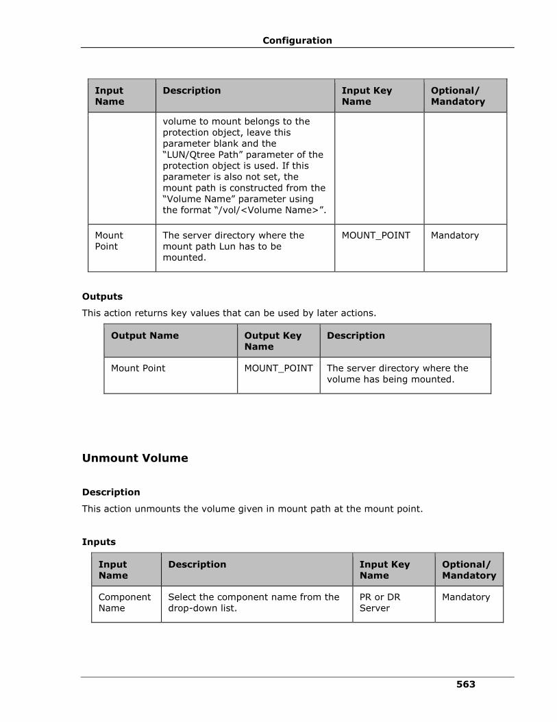
Configuration
563
Input
Name
Description Input Key
Name
Optional/
Mandatory
volume to mount belongs to the
protection object, leave this
parameter blank and the
“LUN/Qtree Path” parameter of the
protection object is used. If this
parameter is also not set, the
mount path is constructed from the
“Volume Name” parameter using
the format “/vol/<Volume Name>”.
Mount
Point
The server directory where the
mount path Lun has to be
mounted.
MOUNT_POINT Mandatory
Outputs
This action returns key values that can be used by later actions.
Output Name Output Key
Name
Description
Mount Point MOUNT_POINT The server directory where the
volume has being mounted.
Unmount Volume
Description
This action unmounts the volume given in mount path at the mount point.
Inputs
Input
Name
Description Input Key
Name
Optional/
Mandatory
Component
Name
Select the component name from the
drop-down list.
PR or DR
Server
Mandatory

IBM Resiliency Orchestration Administrator’s Guide
© IBM Corporation 2017 564
Input
Name
Description Input Key
Name
Optional/
Mandatory
Mount Point The server directory from where the
mount path volume has to be
unmounted.
MOUNT_POINT Mandatory
Outputs
There are no output keys for this action.
Mount Clone Volume
Description
This action mounts the volume given in clone mount path at the mount point.
Inputs
Input
Name
Description Input Key Name Optional/
Mandatory
Component
Name
Select the component
name from the drop-down
list.
Production or DR Server Mandatory
Mount Path The user should provide
the clone mount path with
IP address. He can provide
the same in key
CLONE_MOUNT_PATH.
CLONE_MOUNT_PATH Optional
Mount Point The server directory where
the mount path has to be
mounted.
MOUNT_POINT Mandatory
Outputs
There are no output keys for this action.
Unmount Clone Volume
Description
This action unmounts the volume given in clone mount path at the mount point.

Configuration
565
Inputs
Input
Name
Description Input Key
Name
Optional/
Mandatory
Component
Name
Select the component name from
the drop-down list.
Production or
DR Server
Mandatory
Mount Path The server directory from where the
mount path volume has to be un
mounted.
MOUNT_PATH Mandatory
Outputs
There are no output keys for this action.
Get Volume Size
Description
This action identifies the size of the volume.
Inputs
Input Name Description Input Key Name Optional/
Mandatory
Component
Name
Select the component name
from the drop-down list.
Production or DR
Server
Mandatory
Volume Path The path in which the volume
is configured
VOLUME_PATH Mandatory
Outputs
This action returns the size of the volume.
Output Name Output Key
Name
Description
Volume Path VOLUME_PATH The size of the volume.
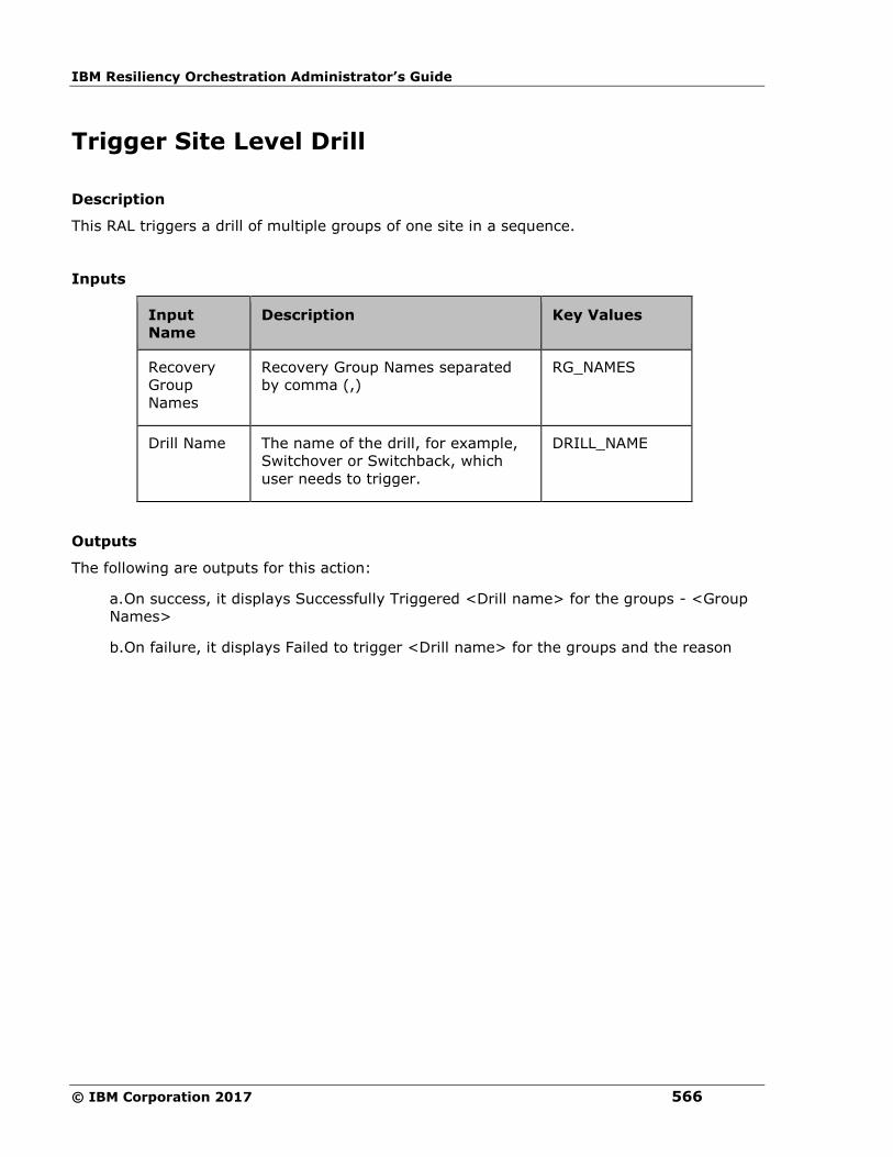
IBM Resiliency Orchestration Administrator’s Guide
© IBM Corporation 2017 566
Trigger Site Level Drill
Description
This RAL triggers a drill of multiple groups of one site in a sequence.
Inputs
Input
Name
Description Key Values
Recovery
Group
Names
Recovery Group Names separated
by comma (,)
RG_NAMES
Drill Name The name of the drill, for example,
Switchover or Switchback, which
user needs to trigger.
DRILL_NAME
Outputs
The following are outputs for this action:
a. On success, it displays Successfully Triggered <Drill name> for the groups - <Group
Names>
b. On failure, it displays Failed to trigger <Drill name> for the groups and the reason
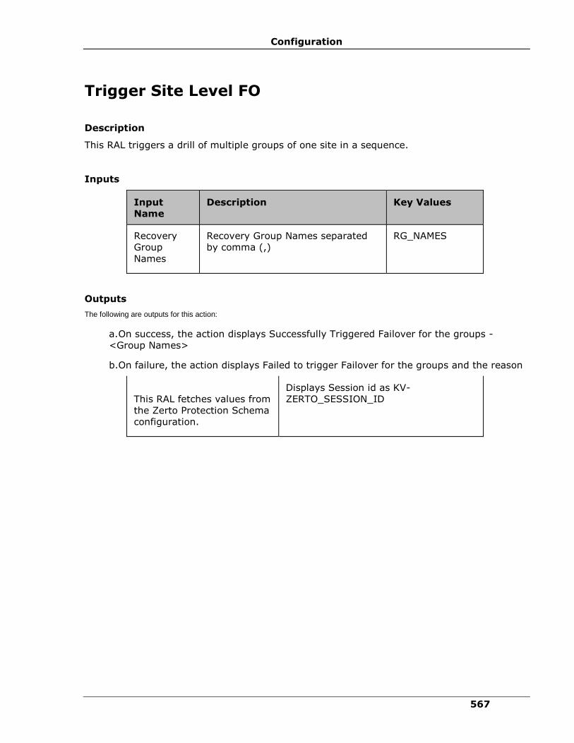
Configuration
567
Trigger Site Level FO
Description
This RAL triggers a drill of multiple groups of one site in a sequence.
Inputs
Input
Name
Description Key Values
Recovery
Group
Names
Recovery Group Names separated
by comma (,)
RG_NAMES
Outputs
The following are outputs for this action:
a. On success, the action displays Successfully Triggered Failover for the groups -
<Group Names>
b. On failure, the action displays Failed to trigger Failover for the groups and the reason
This RAL fetches values from
the Zerto Protection Schema
configuration.
Displays Session id as KV-
ZERTO_SESSION_ID
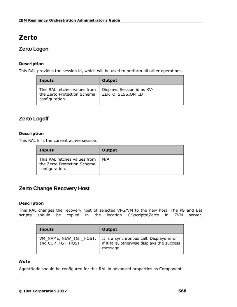
IBM Resiliency Orchestration Administrator’s Guide
© IBM Corporation 2017 568
Zerto
Zerto Logon
Description
This RAL provides the session id, which will be used to perform all other operations.
Inputs Output
This RAL fetches values from
the Zerto Protection Schema
configuration.
Displays Session id as KV-
ZERTO_SESSION_ID
Zerto Logoff
Description
This RAL kills the current active session.
Inputs Output
This RAL fetches values from
the Zerto Protection Schema
configuration.
N/A
Zerto Change Recovery Host
Description
This RAL changes the recovery host of selected VPG/VM to the new host. The PS and Bat
scripts should be copied in the location C:\scripts\Zerto in ZVM server.
Inputs Output
VM_NAME, NEW_TGT_HOST,
and CUR_TGT_HOST
It is a synchronous call. Displays error
if it fails, otherwise displays the success
message.
Note
AgentNode should be configured for this RAL in advanced properties as Component.

Configuration
569
Zerto Delete VRA
Description
This RAL deletes the VRA based on the VRA IP provided as KV.
Input Output
VRA_IP Returns success when VRA is deleted.
Zerto Failover
Description
This RAL triggers the failover over the VPG.
Inputs Output
This RAL fetches values from
the Zerto Protection Schema
configuration.
Returns success when failover is
completed successfully.
Zerto Failover Test
Description
This RAL triggers the failover test on a VPG.
Inputs Output
This RAL fetches values from
the Zerto Protection Schema
configuration.
Returns success when FOTE (Failover
Test Exercise) is completed.
Zerto Force Sync VPG
Description
This RAL will sync VPG (not certified/tested).
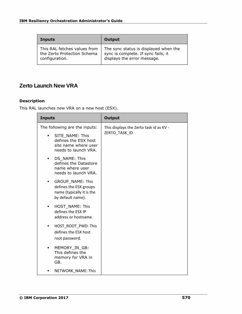
IBM Resiliency Orchestration Administrator’s Guide
© IBM Corporation 2017 570
Inputs Output
This RAL fetches values from
the Zerto Protection Schema
configuration.
The sync status is displayed when the
sync is complete. If sync fails, it
displays the error message.
Zerto Launch New VRA
Description
This RAL launches new VRA on a new host (ESX).
Inputs Output
The following are the inputs:
▪ SITE_NAME: This
defines the ESX host
site name where user
needs to launch VRA.
▪ DS_NAME: This
defines the Datastore
name where user
needs to launch VRA.
▪ GROUP_NAME: This defines the ESX groups name (typically it is the by default name).
▪ HOST_NAME: This defines the ESX IP address or hostname.
▪ HOST_ROOT_PWD: This
defines the ESX host
root password.
▪ MEMORY_IN_GB:
This defines the
memory for VRA in
GB.
▪ NETWORK_NAME: This
This displays the Zerto task id as KV - ZERTO_TASK_ID

Configuration
571
defines the name of the network.
▪ DEF_GATEWAY: This
defines the default
gateway for the
network.
▪ SUBNET_MASK: This
defines the subnet mask
to identify the host.
▪ VRA_IP: This defines the IP address, which can be assigned to VRA.
▪ VRA_IP_CONFIG: This defines the type of IP configuration
required (Static or
Dynamic).
Zerto Resume VPG
Description
This RAL resumes the replication of VPG. This is not certified/tested.
Inputs Output
This RAL fetches values from
the Zerto Protection Schema
configuration.
Displays the error message if
replication fails. Otherwise, the success
message is displayed.
Zerto Unprotect VPG
Description
This RAL deletes the VPG. This is not certified/tested.
Inputs Output
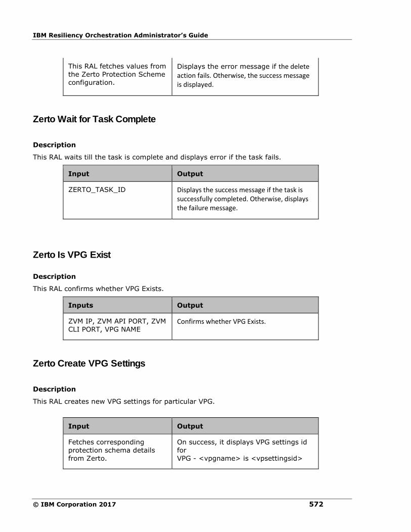
IBM Resiliency Orchestration Administrator’s Guide
© IBM Corporation 2017 572
This RAL fetches values from
the Zerto Protection Scheme
configuration.
Displays the error message if the delete action fails. Otherwise, the success message is displayed.
Zerto Wait for Task Complete
Description
This RAL waits till the task is complete and displays error if the task fails.
Input Output
ZERTO_TASK_ID Displays the success message if the task is successfully completed. Otherwise, displays the failure message.
Zerto Is VPG Exist
Description
This RAL confirms whether VPG Exists.
Inputs Output
ZVM IP, ZVM API PORT, ZVM
CLI PORT, VPG NAME Confirms whether VPG Exists.
Zerto Create VPG Settings
Description
This RAL creates new VPG settings for particular VPG.
Input Output
Fetches corresponding
protection schema details
from Zerto.
On success, it displays VPG settings id
for
VPG - <vpgname> is <vpsettingsid>

Configuration
573
Note
AgentNode should be configured for this RAL in advanced properties as Component.
Zerto Delete VPG
Description
This RAL deletes the Zerto VPG.
Input Output
Fetches corresponding
protection schema details
from Zerto.
The following are outputs:
a. On success, it displays
Successfully deleted <VPGName>
b. On failure, it displays Failed to
delete <VPGNAME>
Low Touch Oracle DG
Supported Features
We support
▪ Linux Platform RHEL 6.0 and above
▪ Oracle version 11.2.0.4.0 Enterprise Edition
▪ Provisioning workflow is provided only for remote agents
▪ By default, AMI is supported from the AWS Marketplace, AMI Id:ami-c0b429a8
https://aws.amazon.com/marketplace/pp/B00J8VRSNY/ref=srh_res_product_title?ie=UTF8&
sr=0-2&qid=1439972392422
The user can find the details of the AMI in the above provided link.

IBM Resiliency Orchestration Administrator’s Guide
© IBM Corporation 2017 574
Overview
The group creation of Oracle DG solution for Cloud/AWS through Low touch Wizards which
simplifies the Oracle DG group creation in RaaS environment follows a few assumptions
which are given below.
▪ This document describes about the group creation of Oracle DG solution through Low
touch Wizards
▪ Oracle Database should be available on the Production site.
▪ Management service should be discovered from IBM Resiliency Orchestration GUI
before initiating Low Touch wizard.
▪ This wizard supports for Linux server 6.0 and above and the database on Oracle
11.2.0.4.0 only.
Prerequisites
The prerequisites for proceeding with the Low Touch wizard are
Configuration Steps: These are set-up/configuration required at IBM Resiliency
Orchestration side before proceeding with the Low Touch Oracle Dataguard provisioning.
▪ Discovering AWS service
Click Discover> Management services> Add management service
Enter the following details to create a new management service
Field Description
Site Select a site from the drop-down list

Configuration
575
Management
Service Type
Select a management service type from the
drop-down list
Management
Service Name
Enter the management service name
Agent Node
Component
Select the agent node component from the
drop-down list
Aws Access Id Enter the Aws access id
Aws Secret Key Enter the AWS Secret key
Click Test Credentials to validate the
information
Click Cancel to cancel the action.
Or
Click Save to create a new management service.
Low Touch Wizard - Primary Server
The low touch wizard is mainly for provisioning the Oracle DB and DG on AWS.
The low touch wizard which simplifies the Oracle DG group creation in RaaS environment
follows a few assumptions and prerequisites.
1 Click DISCOVER > Groups on the navigation bar. The Groups page appears.
2 Click Oracle Recovery with Dataguard on AWS button on the right side of the page.
The Oracle Recovery to AWS Wizard page appears.
▪ Primary Server- Checks for test credentials and creates a Primary Component
▪ Primary Database -Validates the database availability and its credentials. Also
validates the space required to take backup and backup folder permissions.
▪ AWS Information- Provides the details of AWS to Provision DR on AWS with Oracle DB
and DG

IBM Resiliency Orchestration Administrator’s Guide
© IBM Corporation 2017 576
Enter the following details in the fields
Field Description
Type By default,the operating system is Linux.
Server Site Select the Server site from the drop-down list
IP Address
Enter the IP address
Server Managed
Remotely
Select the check box if it is remotely managed
or uncheck it for local agents
Oracle User Name Enter the Oracle user name
Port No. (SSH) Enter the Port no.
Password Enter the Password
Click on Test Credentials to confirm the
entered details
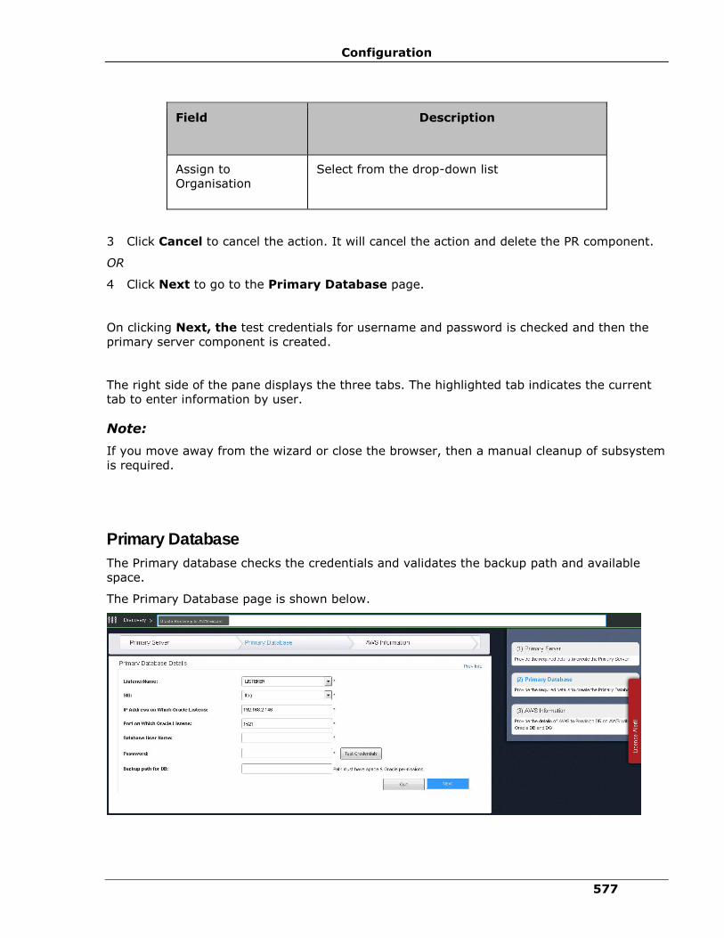
Configuration
577
Field Description
Assign to
Organisation
Select from the drop-down list
3 Click Cancel to cancel the action. It will cancel the action and delete the PR component.
OR
4 Click Next to go to the Primary Database page.
On clicking Next, the test credentials for username and password is checked and then the
primary server component is created.
The right side of the pane displays the three tabs. The highlighted tab indicates the current
tab to enter information by user.
Note:
If you move away from the wizard or close the browser, then a manual cleanup of subsystem
is required.
Primary Database
The Primary database checks the credentials and validates the backup path and available
space.
The Primary Database page is shown below.

IBM Resiliency Orchestration Administrator’s Guide
© IBM Corporation 2017 578
Enter the following details in the fields
Field Description
Listener Name Select Listener from the drop-down list
SID Displays the database SID
IP Address on Which
Oracle Listens
Enter the IP address
Port on Which
Oracle Listens Enter the Port no.
Database User
Name
Enter the Database User name
Password Enter the Password.
Click Test Credentials to confirm the entered
details
Backup path for DB Provide the backup path for the DB
Click Quit to cancel the action or click Next to move to the AWS information page.
On clicking Next we check the test credentials, space validation for backup path and also the
primary database.
To view the previous information, click the Prev Info located on the top right corner of the
page.
The following information is displayed by mousing over the list.
Field Description

Configuration
579
Primary Server Type Displays the Primary Server Type
Primary Server Site Displays the Primary Server Site name
Primary Server IP Displays the Primary Server IP address
Primary Server
Name
Displays the Primary Server name
Primary Server Port Displays the Primary server Port no.
Primary Server User Displays the Primary Server User name
Note:
If you move away from the wizard or close the browser, then a manual cleanup of subsystem
is required.
AWS Information
The AWS information page provides details of AWS for provisioning DR on AWS with Oracle
DB and DG such as Subnet ID, AWS Instance type and AWS Instance Name etc.
The AWS Information page is shown below.

IBM Resiliency Orchestration Administrator’s Guide
© IBM Corporation 2017 580
Enter the following details in the fields
Field Description
DR Site Select the DR Site from the drop-down list
Management
Service
Select the management Service from the drop
- down list
Region Select the Region from the drop-down list
VPC Select the VPC from the drop-down list. This is
dependent on the region
Subnet ID Select the Subnet ID from the drop-down list.
The Subnet ID is dependent on the VPC
Image/AMI ID Select the Image ID from the drop -down list.
AWS Instance Type Select the AWS Instance Type from the drop-
down list.

Configuration
581
Field Description
AWS Instance Name Enter the AWS Instance name
Security Group ID Select the Security Group ID from the
dropdown list. This is dependent on the
Subnet ID
Key Pair Select the keypair from the drop-down list
Upload the Keypair
file
Browse the keypair file and upload
Click Quit to cancel the action. It will cancel the action and delete the PR dataset and the PR
component.
OR
click Provision to start the Provision workflow of a DB and DG.
The workflow will execute Oracle DB/DG provisioning and also create a Oracle DG Group.
On clicking Provision the Workflow Execution page is displayed.
On mousing over the Prev Info the details of the Primary Server and Primary Database is
displayed in a drop-down box.
Field Description
Primary Server Type Displays the Primary Server Type
Primary Server Site Displays the Primary Server Site name
Primary Server IP Displays the Primary Server IP address
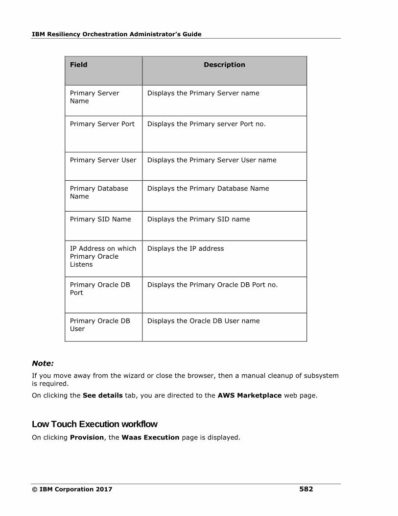
IBM Resiliency Orchestration Administrator’s Guide
© IBM Corporation 2017 582
Field Description
Primary Server
Name
Displays the Primary Server name
Primary Server Port Displays the Primary server Port no.
Primary Server User Displays the Primary Server User name
Primary Database
Name
Displays the Primary Database Name
Primary SID Name Displays the Primary SID name
IP Address on which
Primary Oracle
Listens
Displays the IP address
Primary Oracle DB
Port
Displays the Primary Oracle DB Port no.
Primary Oracle DB
User
Displays the Oracle DB User name
Note:
If you move away from the wizard or close the browser, then a manual cleanup of subsystem
is required.
On clicking the See details tab, you are directed to the AWS Marketplace web page.
Low Touch Execution workflow
On clicking Provision, the Waas Execution page is displayed.
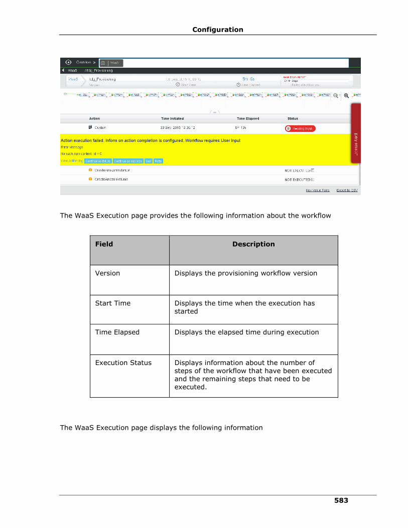
Configuration
583
The WaaS Execution page provides the following information about the workflow
Field Description
Version Displays the provisioning workflow version
Start Time Displays the time when the execution has
started
Time Elapsed Displays the elapsed time during execution
Execution Status Displays information about the number of
steps of the workflow that have been executed
and the remaining steps that need to be
executed.
The WaaS Execution page displays the following information
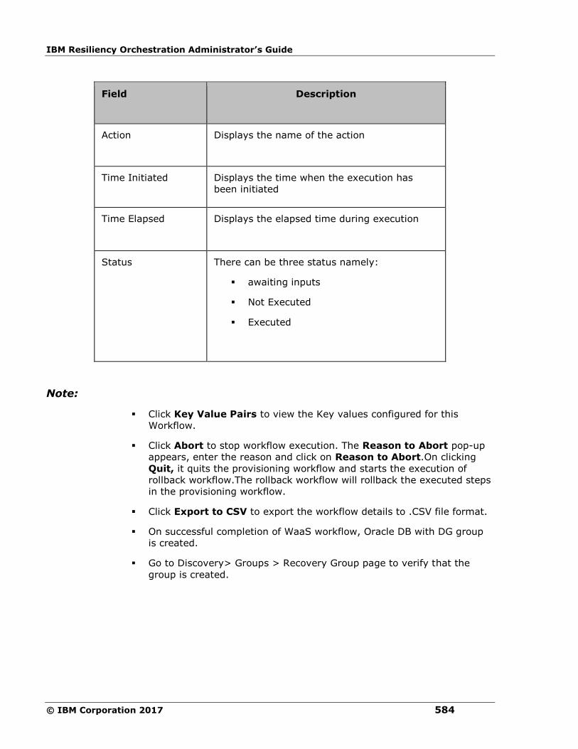
IBM Resiliency Orchestration Administrator’s Guide
© IBM Corporation 2017 584
Field Description
Action Displays the name of the action
Time Initiated Displays the time when the execution has
been initiated
Time Elapsed Displays the elapsed time during execution
Status There can be three status namely:
▪ awaiting inputs
▪ Not Executed
▪ Executed
Note:
▪ Click Key Value Pairs to view the Key values configured for this
Workflow.
▪ Click Abort to stop workflow execution. The Reason to Abort pop-up
appears, enter the reason and click on Reason to Abort.On clicking
Quit, it quits the provisioning workflow and starts the execution of
rollback workflow.The rollback workflow will rollback the executed steps
in the provisioning workflow.
▪ Click Export to CSV to export the workflow details to .CSV file format.
▪ On successful completion of WaaS workflow, Oracle DB with DG group
is created.
▪ Go to Discovery> Groups > Recovery Group page to verify that the
group is created.

Configuration
585
Configuration
Configuring RPO/ RTO
Click IBM Resiliency Orchestration Server User Role Management to see the privileges.
To configure RPO and RTO values for a Group, do the following:
1. Click DISCOVER > Groups on the navigation bar. The Groups page appears.
2. Click Recovery Group tab, the Recovery Group Listing page appears.
3. Click the required group from the GROUP NAME column. The Group Details Page
appears.
4. Click the Group Configuration tab.
5. Click the RPO/ RTO tab. This page allows you to configure the RPO/ RTO details of the
RG.
Configure the RPO/ RTO by providing following information:
Field Description
Desired RPO Enter the RPO goal for the application.
Note:
This field is mandatory and accepts numerals. The
value is entered either in seconds, minutes or hours
and maximum value that can be entered is calculated
for a month (i.e. maximum value for seconds is 24
(hours in a day)*60*60*30 (per month)).
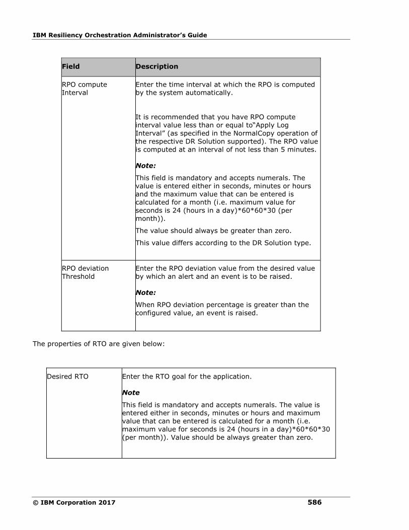
IBM Resiliency Orchestration Administrator’s Guide
© IBM Corporation 2017 586
Field Description
RPO compute
Interval
Enter the time interval at which the RPO is computed
by the system automatically.
It is recommended that you have RPO compute
interval value less than or equal to“Apply Log
Interval” (as specified in the NormalCopy operation of
the respective DR Solution supported). The RPO value
is computed at an interval of not less than 5 minutes.
Note:
This field is mandatory and accepts numerals. The
value is entered either in seconds, minutes or hours
and the maximum value that can be entered is
calculated for a month (i.e. maximum value for
seconds is 24 (hours in a day)*60*60*30 (per
month)).
The value should always be greater than zero.
This value differs according to the DR Solution type.
RPO deviation
Threshold
Enter the RPO deviation value from the desired value
by which an alert and an event is to be raised.
Note:
When RPO deviation percentage is greater than the
configured value, an event is raised.
The properties of RTO are given below:
Desired RTO Enter the RTO goal for the application.
Note
This field is mandatory and accepts numerals. The value is
entered either in seconds, minutes or hours and maximum
value that can be entered is calculated for a month (i.e.
maximum value for seconds is 24 (hours in a day)*60*60*30
(per month)). Value should be always greater than zero.
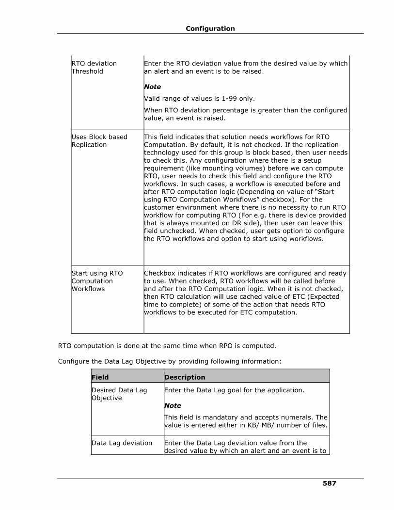
Configuration
587
RTO deviation
Threshold
Enter the RTO deviation value from the desired value by which
an alert and an event is to be raised.
Note
Valid range of values is 1-99 only.
When RTO deviation percentage is greater than the configured
value, an event is raised.
Uses Block based
Replication
This field indicates that solution needs workflows for RTO
Computation. By default, it is not checked. If the replication
technology used for this group is block based, then user needs
to check this. Any configuration where there is a setup
requirement (like mounting volumes) before we can compute
RTO, user needs to check this field and configure the RTO
workflows. In such cases, a workflow is executed before and
after RTO computation logic (Depending on value of “Start
using RTO Computation Workflows” checkbox). For the
customer environment where there is no necessity to run RTO
workflow for computing RTO (For e.g. there is device provided
that is always mounted on DR side), then user can leave this
field unchecked. When checked, user gets option to configure
the RTO workflows and option to start using workflows.
Start using RTO
Computation
Workflows
Checkbox indicates if RTO workflows are configured and ready
to use. When checked, RTO workflows will be called before
and after the RTO Computation logic. When it is not checked,
then RTO calculation will use cached value of ETC (Expected
time to complete) of some of the action that needs RTO
workflows to be executed for ETC computation.
RTO computation is done at the same time when RPO is computed.
Configure the Data Lag Objective by providing following information:
Field Description
Desired Data Lag
Objective
Enter the Data Lag goal for the application.
Note
This field is mandatory and accepts numerals. The
value is entered either in KB/ MB/ number of files.
Data Lag deviation Enter the Data Lag deviation value from the
desired value by which an alert and an event is to
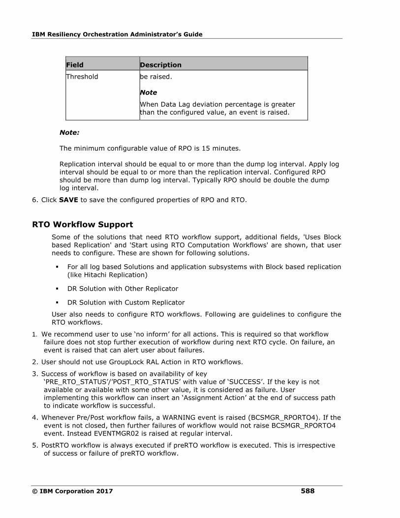
IBM Resiliency Orchestration Administrator’s Guide
© IBM Corporation 2017 588
Field Description
Threshold be raised.
Note
When Data Lag deviation percentage is greater
than the configured value, an event is raised.
Note:
The minimum configurable value of RPO is 15 minutes.
Replication interval should be equal to or more than the dump log interval. Apply log
interval should be equal to or more than the replication interval. Configured RPO
should be more than dump log interval. Typically RPO should be double the dump
log interval.
6. Click SAVE to save the configured properties of RPO and RTO.
RTO Workflow Support
Some of the solutions that need RTO workflow support, additional fields, 'Uses Block
based Replication' and 'Start using RTO Computation Workflows' are shown, that user
needs to configure. These are shown for following solutions.
▪ For all log based Solutions and application subsystems with Block based replication
(like Hitachi Replication)
▪ DR Solution with Other Replicator
▪ DR Solution with Custom Replicator
User also needs to configure RTO workflows. Following are guidelines to configure the
RTO workflows.
1. We recommend user to use ‘no inform’ for all actions. This is required so that workflow
failure does not stop further execution of workflow during next RTO cycle. On failure, an
event is raised that can alert user about failures.
2. User should not use GroupLock RAL Action in RTO workflows.
3. Success of workflow is based on availability of key
‘PRE_RTO_STATUS’/’POST_RTO_STATUS’ with value of ‘SUCCESS’. If the key is not
available or available with some other value, it is considered as failure. User
implementing this workflow can insert an ‘Assignment Action’ at the end of success path
to indicate workflow is successful.
4. Whenever Pre/Post workflow fails, a WARNING event is raised (BCSMGR_RPORTO4). If the
event is not closed, then further failures of workflow would not raise BCSMGR_RPORTO4
event. Instead EVENTMGR02 is raised at regular interval.
5. PostRTO workflow is always executed if preRTO workflow is executed. This is irrespective
of success or failure of preRTO workflow.

Configuration
589
6. If pre RTO workflow fails, RTO would include cached value/default value for some of the
actions that are dependent on RTO workflows.
7. While computing RTO, some of the actions are going to returned cached value for ETC.
That means, these value would have collected at different timestamps. In such cases,
RTO as of time is shown to be timestamp of ETC computed having oldest compute
time. For e.g. If there are 2 actions in FO workflow, action1 has cached value collected at
time 10 AM, action2 has ETC computed at current time (lets say 10:30 AM), then ‘RTO as
of time’ value would be 10AM.
8. RTO workflows are ‘system workflows’ and would NOT be shown under ‘Workflowlist’ tab.
9. In reports page, these workflows are shown if ‘Show System Workflow’ checkbox is
checked.
In addition to the above configuration, RPO and RTO values are specific to solutions. These
specific values are configured depending on the type of the solution supported.
Configuring Notification Regarding Events
Click IBM Resiliency Orchestration Server User Role Management to see the privileges.
To configure Notification regarding Events, perform the following:
1 Click DISCOVER > Groups on the navigation bar. The Groups page appears.
2 Click Recovery Group tab, the Recovery Group Listing page appears.
3 Click the required group from the GROUP NAME column. The Group Details Page
appears.
4 Click the Group Configuration tab.
5 Click the Events tab.
Field Description
Event ID Displays the respective Event ID which
identifies each event.
Event Description Provides a brief description of the respective
event.
Event Severity Displays the level of severity of the respective
event.
Is _Alertable Events whose alertable field is true will be
displayed in the UI
Impact_GroupStatus Events whose Impact_GroupStatus field is
true, those events will impact the group

IBM Resiliency Orchestration Administrator’s Guide
© IBM Corporation 2017 590
status health and continuity
Event Impact Provides information on affect/effects about
the event.
Notify Allows you to send notification regarding the
event to the user.
By default, SERIOUS and CRITICAL events are
notified.
6 Select the check boxes corresponding to the Events for which you want to notify the
user on occurrence of it.
Note:
To receive notification regarding the event, at least one notification list must be associated
with the group. For more information on creating notification list, refer to Adding
Notification List.
7 Click Update Selection button.
Configuring Event Policy
Events or Incidents occur as a consequence of a problem with Components, Datasets or
Protection Schemes. A Group is configured with all possible Events/Incidents depending up
on the solution type.
Click IBM Resiliency Orchestration Server User Role Management to see the privileges.
General Definitions:
Field Description
Event A casualty resulting in production data down.
An incident is an event with the highest
severity level (threat level).
Incident Consequences as a result of something
happened on an object.
To configure Events, perform the following:
1. Click DISCOVER > Groups on the navigation bar. The Groups page appears.
2. Click the Recovery Group tab, the Recovery Group Listing page appears.

Configuration
591
3. Click the required group from the GROUP NAME column. The Group Details page
appears.
4. Click the Group Configuration > Events tab.
This tabbed page lists the Event ID, it's description, severity and impact. You can select the
check boxes corresponding to the events for which you want to send notification to the user.
5. Click the Event ID link corresponding to the Event you want to configure. The Event
Configuration Details page is displayed providing information on the Event's
configuration along with the Policy Set Details as given below:
Field Description
Configuration for Event
Group Name Displays the Group name.
Event ID Displays the respective Event ID which
identifies each event.
Severity Displays the level of severity of the respective
event.
Is_ Alertable Events whose alertable is true will be displayed
in the UI
Description Provides a brief description of the respective
event.
Event Impact Provides information on affect/effects about the
event.
Impact_group
status
Displays the impact of the event on the group
status.
Notify
Update Selection
Select the checkbox to notify the updates
A Policy Set is defined as a combination of actions with respect to both day and night policy.
The Policy Set Details displays the following information:
Field Description
POLICY Displays the policy name

IBM Resiliency Orchestration Administrator’s Guide
© IBM Corporation 2017 592
Field Description
Note:
There can be multiple instances of same Event
raised for a Group that require execution of
same policy. However, only one instance of a
policy can run at a time. In such cases, the
later instances of the event are put to FAILED
status.
For example, there are three instances of Event
E- E1, E2, and E3, raised for Group G, requiring
the execution of policy P. If P is being executed
for E1, its execution for E2 and E3 will be put
to FAILED status. Once the policy execution for
a Event is put to FAILED status, it cannot be
initiated again.
Instances of same event for different Group do
not affect each other.
TIME OF DAY Gives time of day when this policy will be
effective. (Currently, the time of day is always
24 hours). For example, the policy page shows
a timing gap of ’00:00 to 23:59’ hours, which
ultimately mean that the workflow, will get
executed when the incident occurs at any time
with in the given range of a day.
WORKFLOW NAME Displays the workflow name which is always
associated to the policy.
POLICY
EXECUTION MODE You can set this field to Manual or Auto.
Manual selection requires your intervention to
execute a policy.
6. Click workflow name link under WORKFLOW NAME column to configure the
workflow associated to the policy.
Adding Polar Event Script
This tool is used to manually add the polar cancellation to the events for which polar
cancellation is not implemented.
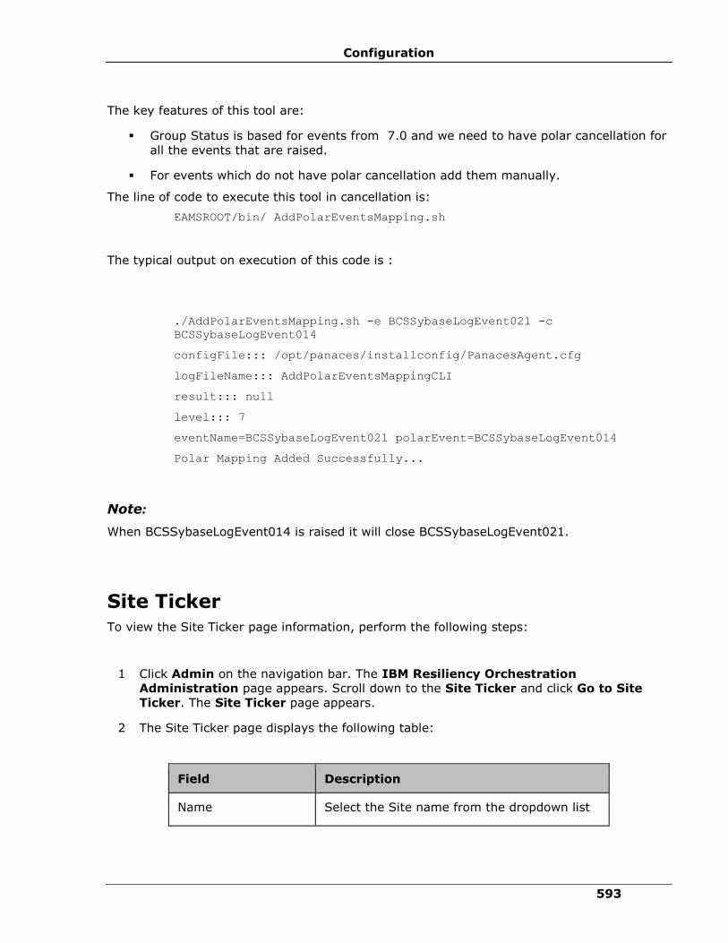
Configuration
593
The key features of this tool are:
▪ Group Status is based for events from 7.0 and we need to have polar cancellation for
all the events that are raised.
▪ For events which do not have polar cancellation add them manually.
The line of code to execute this tool in cancellation is:
EAMSROOT/bin/ AddPolarEventsMapping.sh
The typical output on execution of this code is :
./AddPolarEventsMapping.sh -e BCSSybaseLogEvent021 -c
BCSSybaseLogEvent014
configFile::: /opt/panaces/installconfig/PanacesAgent.cfg
logFileName::: AddPolarEventsMappingCLI
result::: null
level::: 7
eventName=BCSSybaseLogEvent021 polarEvent=BCSSybaseLogEvent014
Polar Mapping Added Successfully...
Note:
When BCSSybaseLogEvent014 is raised it will close BCSSybaseLogEvent021.
Site Ticker
To view the Site Ticker page information, perform the following steps:
1 Click Admin on the navigation bar. The IBM Resiliency Orchestration
Administration page appears. Scroll down to the Site Ticker and click Go to Site
Ticker. The Site Ticker page appears.
2 The Site Ticker page displays the following table:
Field Description
Name Select the Site name from the dropdown list
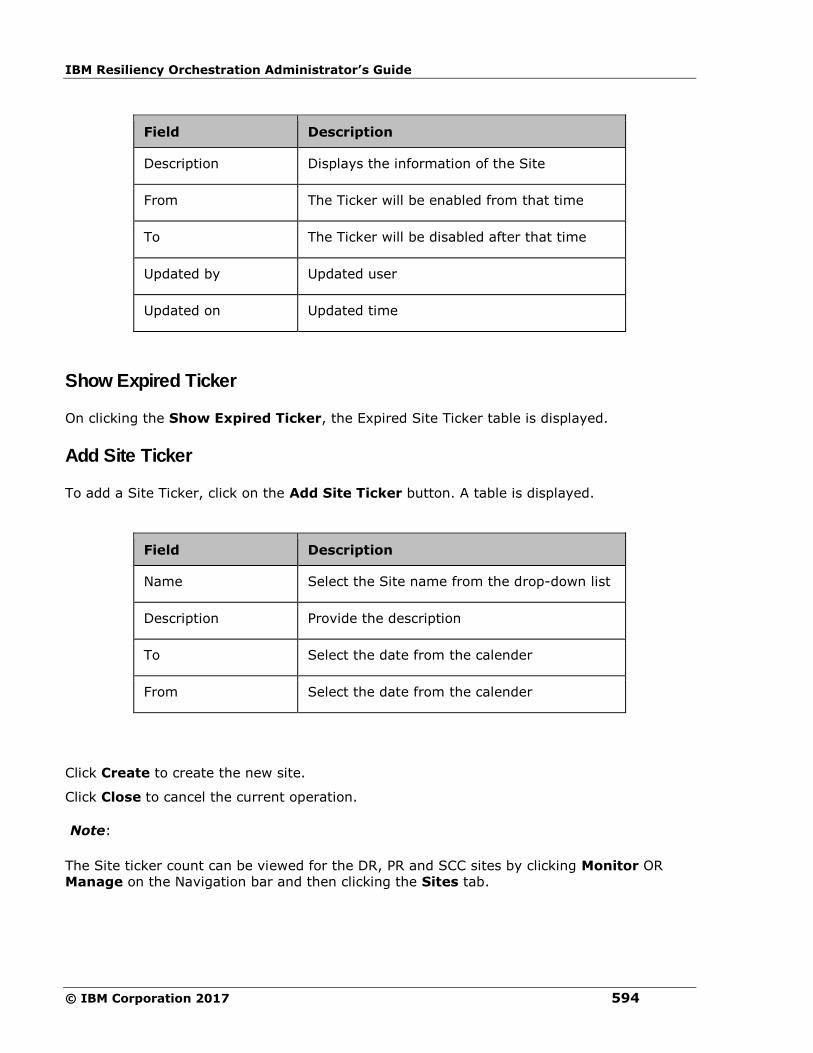
IBM Resiliency Orchestration Administrator’s Guide
© IBM Corporation 2017 594
Field Description
Description Displays the information of the Site
From The Ticker will be enabled from that time
To The Ticker will be disabled after that time
Updated by Updated user
Updated on Updated time
Show Expired Ticker
On clicking the Show Expired Ticker, the Expired Site Ticker table is displayed.
Add Site Ticker
To add a Site Ticker, click on the Add Site Ticker button. A table is displayed.
Field Description
Name Select the Site name from the drop-down list
Description Provide the description
To Select the date from the calender
From Select the date from the calender
Click Create to create the new site.
Click Close to cancel the current operation.
Note:
The Site ticker count can be viewed for the DR, PR and SCC sites by clicking Monitor OR
Manage on the Navigation bar and then clicking the Sites tab.
Configuration
595
Vault Framework
Introduction
About Vault Framework
Vault is a password management software and its goal is to help organizations secure,
manage and track credentials for sensitive data and critical systems. Centralized
management of passwords at different levels, such as the operating system, database and
application level makes this highly effective and efficient.
The Vault Framework is a high-level framework that provides reusable business logic for
clients to integrate their applications, GUI controls and workflows with different Vault
algorithms. Extensive vault components enable seamless integration with the client’s
applications. The Framework provides enough flexibility to the clients to design an approach
that suits there requirements.
The next section provides Vault components, providers and functionalities common to any
Vault.
Vault Artefacts: Vault artefacts are essential for IBM Resiliency Orchestration to
communicate with any vendor specific Vault.
▪ Connection Parameter: Connection parameters are static for a specific vault. They
must be configured and can be seen in the IBM Resiliency Orchestration GUI, under
Discover >Credentials>ConfigureVault.
▪ Query Parameter: Query parameters are different for every subsystem. They must be
configured and can be seen in the IBM Resiliency Orchestration GUI, under Discover
>Subsystem>Components, Discover >Subsystem>Datasets and Discover
>Subsystem>Protection Schemes, when you select the Vault Type and select the
‘Fetch from Vault’ option.
Vault Providers: Vault providers are the APIs, JARs and Binaries that need to be configured
on the server and are specific to the Vault.
Vault Features: The following features are common to every vendor specific Vault software.
For more information on vault features refer to Vault Features
▪ Password Management and Password Caching: With password management, the Vault
agent encrypts the password for IBM Resiliency Orchestration and decrypts the
password just before making a call to the underlying system. The passwords are
cached at regular intervals and also get updated every time there is an inconsistency
of password in the Vault and the cache.
▪ Locking Agents Mechanism: The locking mechanism is applicable for subsystems
configured with Vault. The locking mechanism. The locking mechanism is designed
such that the agent locks all the calls to the underlying subsystem the moment a cred
fail is encountered. This avoids locking the underlying subsystem user to a great
extent.

IBM Resiliency Orchestration Administrator’s Guide
© IBM Corporation 2017 596
Integration with IBM Resiliency Orchestration
With minimal configuration, IBM Resiliency Orchestration integrates with vendor specific
Vault for clients who have implemented Vault password management software. IBM
Resiliency Orchestration passes the connection parameters and query parameters to the
Vault Agent. The agent executes the tcl script. This script acts like a medium between the
Vault agent and the Vault. All the required parameters to make request to the vendor specific
Vault are available with the tcl file. The TCL script will call the relevant Vault APIs, establish
communication (connection to the configured Vault server), and serve the (password)
requests from the Vault agent.
This integration has the following benefits:
1. It ensures that the user does not have to manually enter the username and password
to login to the IBM Resiliency Orchestration GUI.
2. Change in password in any of the Vault integrated client systems does not have an
impact on the Resiliency Orchestration Application as these changes are recognized by
Vault and the latest correct password is pushed to IBM Resiliency Orchestration GUI.
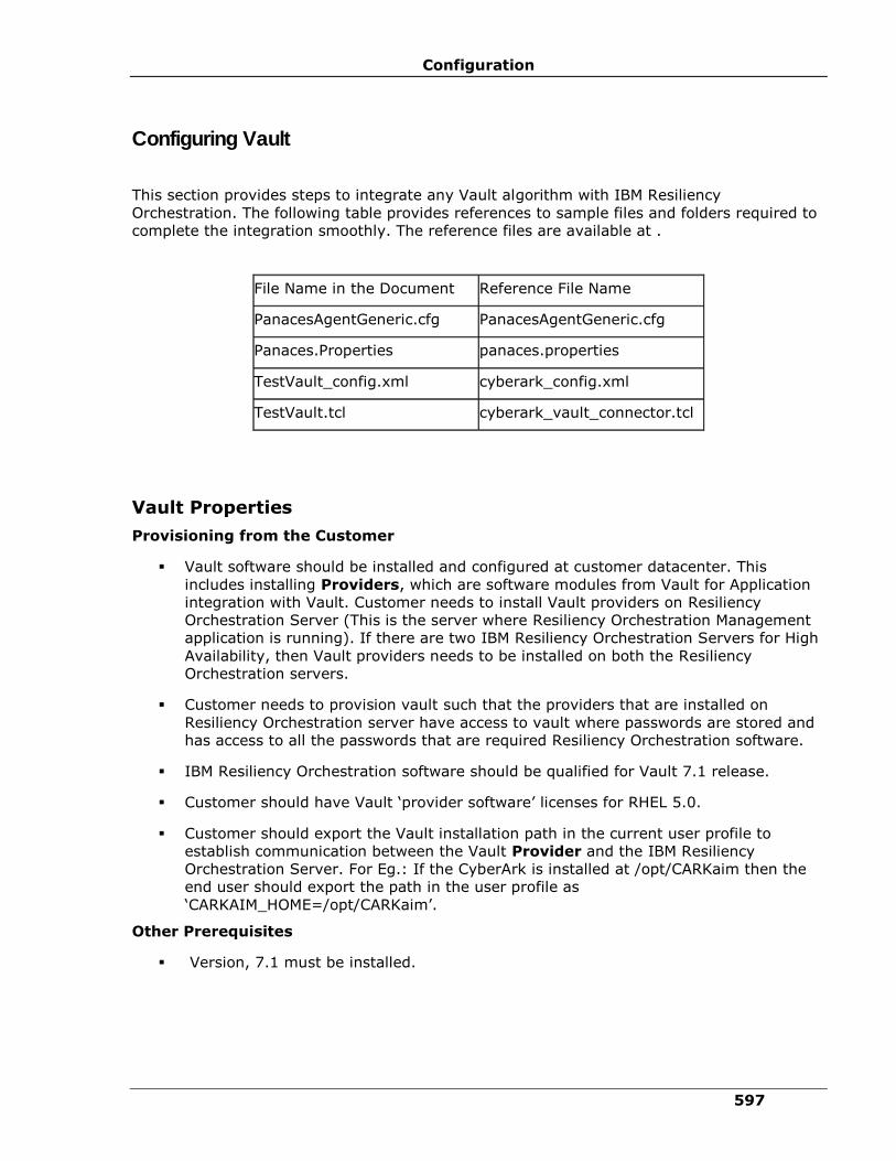
Configuration
597
Configuring Vault
This section provides steps to integrate any Vault algorithm with IBM Resiliency
Orchestration. The following table provides references to sample files and folders required to
complete the integration smoothly. The reference files are available at .
File Name in the Document Reference File Name
PanacesAgentGeneric.cfg PanacesAgentGeneric.cfg
Panaces.Properties panaces.properties
TestVault_config.xml cyberark_config.xml
TestVault.tcl cyberark_vault_connector.tcl
Vault Properties
Provisioning from the Customer
▪ Vault software should be installed and configured at customer datacenter. This
includes installing Providers, which are software modules from Vault for Application
integration with Vault. Customer needs to install Vault providers on Resiliency
Orchestration Server (This is the server where Resiliency Orchestration Management
application is running). If there are two IBM Resiliency Orchestration Servers for High
Availability, then Vault providers needs to be installed on both the Resiliency
Orchestration servers.
▪ Customer needs to provision vault such that the providers that are installed on
Resiliency Orchestration server have access to vault where passwords are stored and
has access to all the passwords that are required Resiliency Orchestration software.
▪ IBM Resiliency Orchestration software should be qualified for Vault 7.1 release.
▪ Customer should have Vault ‘provider software’ licenses for RHEL 5.0.
▪ Customer should export the Vault installation path in the current user profile to
establish communication between the Vault Provider and the IBM Resiliency
Orchestration Server. For Eg.: If the CyberArk is installed at /opt/CARKaim then the
end user should export the path in the user profile as
‘CARKAIM_HOME=/opt/CARKaim’.
Other Prerequisites
▪ Version, 7.1 must be installed.
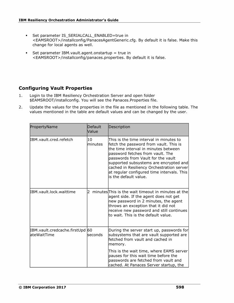
IBM Resiliency Orchestration Administrator’s Guide
© IBM Corporation 2017 598
▪ Set parameter IS_SERIALCALL_ENABLED=true in
<EAMSROOT>/installconfig/PanacesAgentGeneric.cfg. By default it is false. Make this
change for local agents as well.
▪ Set parameter IBM.vault.agent.onstartup = true in
<EAMSROOT>/installconfig/panaces.properties. By default it is false.
Configuring Vault Properties
1. Login to the IBM Resiliency Orchestration Server and open folder
$EAMSROOT/installconfig. You will see the Panaces.Properties file.
2. Update the values for the properties in the file as mentioned in the following table. The
values mentioned in the table are default values and can be changed by the user.
PropertyName Default
Value
Description
IBM.vault.cred.refetch 10
minutes
This is the time interval in minutes to
fetch the password from vault. This is
the time interval in minutes between
password fetches from vault. The
passwords from Vault for the vault
supported subsystems are encrypted and
cached in Resiliency Orchestration server
at regular configured time intervals. This
is the default value.
IBM.vault.lock.waittime 2 minutes
This is the wait timeout in minutes at the
agent side. If the agent does not get
new password in 2 minutes, the agent
throws an exception that it did not
receive new password and still continues
to wait. This is the default value.
IBM.vault.credcache.firstUpd
ateWaitTime
60
seconds
During the server start up, passwords for
subsystems that are vault supported are
fetched from vault and cached in
memory.
This is the wait time, where EAMS server
pauses for this wait time before the
passwords are fetched from vault and
cached. At Panaces Server startup, the
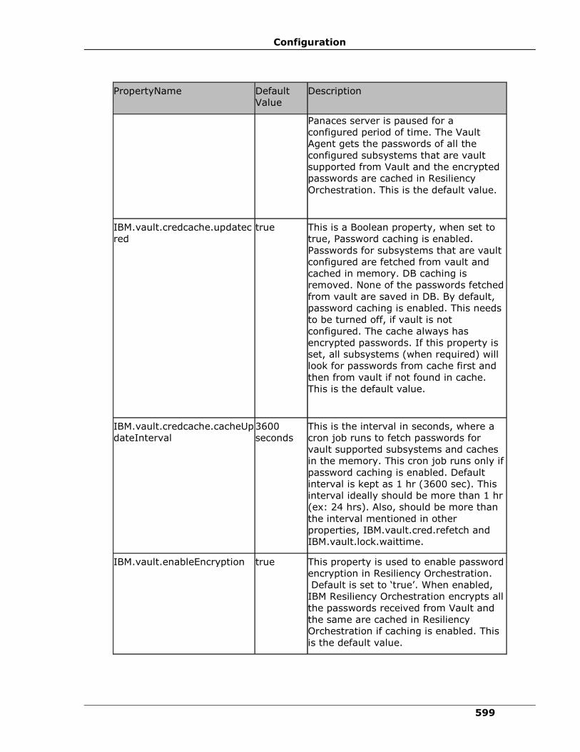
Configuration
599
PropertyName Default
Value
Description
Panaces server is paused for a
configured period of time. The Vault
Agent gets the passwords of all the
configured subsystems that are vault
supported from Vault and the encrypted
passwords are cached in Resiliency
Orchestration. This is the default value.
IBM.vault.credcache.updatec
red
true This is a Boolean property, when set to
true, Password caching is enabled.
Passwords for subsystems that are vault
configured are fetched from vault and
cached in memory. DB caching is
removed. None of the passwords fetched
from vault are saved in DB. By default,
password caching is enabled. This needs
to be turned off, if vault is not
configured. The cache always has
encrypted passwords. If this property is
set, all subsystems (when required) will
look for passwords from cache first and
then from vault if not found in cache.
This is the default value.
IBM.vault.credcache.cacheUp
dateInterval
3600
seconds
This is the interval in seconds, where a
cron job runs to fetch passwords for
vault supported subsystems and caches
in the memory. This cron job runs only if
password caching is enabled. Default
interval is kept as 1 hr (3600 sec). This
interval ideally should be more than 1 hr
(ex: 24 hrs). Also, should be more than
the interval mentioned in other
properties, IBM.vault.cred.refetch and
IBM.vault.lock.waittime.
IBM.vault.enableEncryption true This property is used to enable password
encryption in Resiliency Orchestration.
Default is set to ‘true’. When enabled,
IBM Resiliency Orchestration encrypts all
the passwords received from Vault and
the same are cached in Resiliency
Orchestration if caching is enabled. This
is the default value.

IBM Resiliency Orchestration Administrator’s Guide
© IBM Corporation 2017 600
PropertyName Default
Value
Description
IBM.vault.agent.onstartup false This property enables Vault agent to be
started before other remote agents start.
If this is set to true, the Panaces server
is paused for sometime, till the Vault
Agent starts.
If this is set to false, the Panaces server
will not be paused till the Vault Agent
starts, and the Vault agent gets started
along with all other remote agents.
By default, this property is set to false.
This property needs to be set to true, if
the client is using Vault.
Note: This property was introduced in
Vault Version 2.0
network.disconnect.threshold 2 minutes This property enables Vault to raise the
network down event after the specified
time has lapsed after the network has
gone down.
Configuring New Vault
This section provides instructions on configuring a new vault.
Note: To configure a new Vault, for example ‘TestVault’ in IBM Resiliency Orchestration Server using TCL, create a new folder ‘TestVault’
under $EAMSROOT/agent/vault/ and follow the steps below.
1. Login to the IBM Resiliency Orchestration Server
2. Create the following sub-folders under <EAMSROOT>/agents/vault/TestVault
folder.
a. /config/
b. /lib/
c. /script/
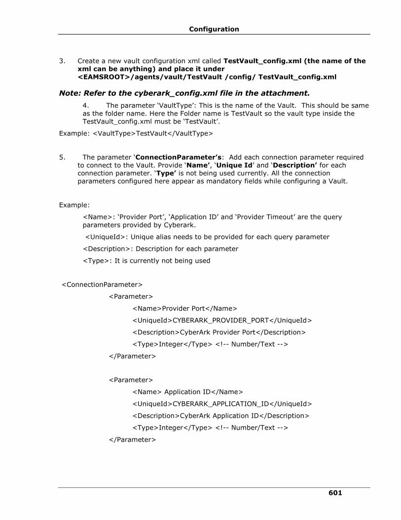
Configuration
601
3. Create a new vault configuration xml called TestVault_config.xml (the name of the
xml can be anything) and place it under
<EAMSROOT>/agents/vault/TestVault /config/ TestVault_config.xml
Note: Refer to the cyberark_config.xml file in the attachment.
4. The parameter ‘VaultType’: This is the name of the Vault. This should be same
as the folder name. Here the Folder name is TestVault so the vault type inside the
TestVault_config.xml must be ‘TestVault’.
Example: <VaultType>TestVault</VaultType>
5. The parameter ‘ConnectionParameter’s: Add each connection parameter required
to connect to the Vault. Provide ‘Name’, ‘Unique Id’ and ‘Description’ for each
connection parameter. ‘Type’ is not being used currently. All the connection
parameters configured here appear as mandatory fields while configuring a Vault.
Example:
<Name>: ‘Provider Port’, ‘Application ID’ and ‘Provider Timeout’ are the query
parameters provided by Cyberark.
<UniqueId>: Unique alias needs to be provided for each query parameter
<Description>: Description for each parameter
<Type>: It is currently not being used
<ConnectionParameter>
<Parameter>
<Name>Provider Port</Name>
<UniqueId>CYBERARK_PROVIDER_PORT</UniqueId>
<Description>CyberArk Provider Port</Description>
<Type>Integer</Type> <!-- Number/Text -->
</Parameter>
<Parameter>
<Name> Application ID</Name>
<UniqueId>CYBERARK_APPLICATION_ID</UniqueId>
<Description>CyberArk Application ID</Description>
<Type>Integer</Type> <!-- Number/Text -->
</Parameter>
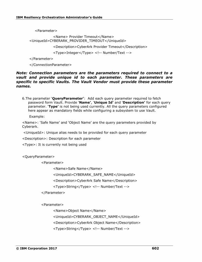
IBM Resiliency Orchestration Administrator’s Guide
© IBM Corporation 2017 602
<Parameter>
<Name> Provider Timeout</Name>
<UniqueId>CYBERARK_PROVIDER_TIMEOUT</UniqueId>
<Description>CyberArk Provider Timeout</Description>
<Type>Integer</Type> <!-- Number/Text -->
</Parameter>
</ConnectionParameter>
Note: Connection parameters are the parameters required to connect to a vault and provide unique id to each parameter. These parameters are
specific to specific Vaults. The Vault Vendor must provide these parameter names.
6. The parameter ‘QueryParameter’: Add each query parameter required to fetch
password form Vault. Provide ‘Name’, ‘Unique Id’ and ‘Description’ for each query
parameter. ‘Type’ is not being used currently. All the query parameters configured
here appear as mandatory fields while configuring a subsystem to use Vault.
Example:
<Name>: ‘Safe Name’ and ‘Object Name’ are the query parameters provided by
Cyberark.
<UniqueId>: Unique alias needs to be provided for each query parameter
<Description>: Description for each parameter
<Type>: It is currently not being used
<QueryParameter>
<Parameter>
<Name>Safe Name</Name>
<UniqueId>CYBERARK_SAFE_NAME</UniqueId>
<Description>CyberArk Safe Name</Description>
<Type>String</Type> <!-- Number/Text -->
</Parameter>
<Parameter>
<Name>Object Name</Name>
<UniqueId>CYBERARK_OBJECT_NAME</UniqueId>
<Description>CyberArk Object Name</Description>
<Type>String</Type> <!-- Number/Text -->
Configuration
603
</Parameter>
</QueryParameter>
Note: Query parameters are the parameters required to fetch password
from vault and provide unique id to each parameter. These parameters are specific to specific Vaults. The Vault Vendor must provide these parameter names.
7. Verify that the parameter <Connector> in the TestVault_config.xml is
<Connector>panaces.agents.vault.vaultagent.vaulttclconnector.VaultTclExec
utor</Connector>
8. Create a new tcl file, TestVault.tcl under
<EAMSROOT>/agents/vault/Arcos/script/
Note: Refer to the sample cyberark_vault connector.tcl file
9. Modify the parameter <args> in the TestVault_config.xml to point to the newly
created tcl file. This absolute path must be mentioned.
Example:
<args>/agents/vault/TestVault/script/TestVault.tcl</args>.
Note: Also, refer to sample cyberark_config.xml file
args tag should be relative path starting from /agents
Refer to the sample cyberark_vault connector.tcl file
To get the configured parameter in IBM Resiliency Orchestration in your
TCL
Call set parameter = [getKeyValue "UniqueID configured in xml "]
Example:
set providerPort [getKeyValue "CYBERARK_PROVIDER_PORT"]
Note: Please refer set sample cyberark_vault connector.tcl file
10. Add all vault specific libraries required to connect to vault to be kept under
<EAMSROOT>/agents/vault/TestVault/lib
Note: Refer to the attached zipped lib folder to understand the file structure and all the files in the lib directory.
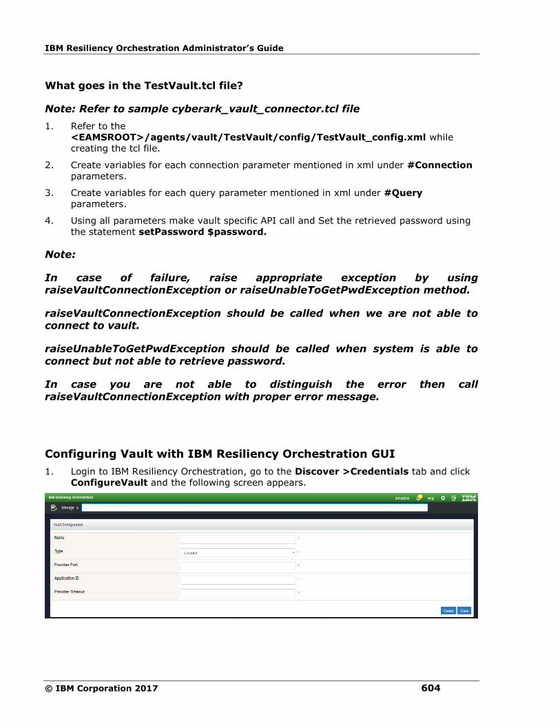
IBM Resiliency Orchestration Administrator’s Guide
© IBM Corporation 2017 604
What goes in the TestVault.tcl file?
Note: Refer to sample cyberark_vault_connector.tcl file
1. Refer to the
<EAMSROOT>/agents/vault/TestVault/config/TestVault_config.xml while
creating the tcl file.
2. Create variables for each connection parameter mentioned in xml under #Connection
parameters.
3. Create variables for each query parameter mentioned in xml under #Query
parameters.
4. Using all parameters make vault specific API call and Set the retrieved password using
the statement setPassword $password.
Note:
In case of failure, raise appropriate exception by using raiseVaultConnectionException or raiseUnableToGetPwdException method.
raiseVaultConnectionException should be called when we are not able to connect to vault.
raiseUnableToGetPwdException should be called when system is able to
connect but not able to retrieve password.
In case you are not able to distinguish the error then call
raiseVaultConnectionException with proper error message.
Configuring Vault with IBM Resiliency Orchestration GUI
1. Login to IBM Resiliency Orchestration, go to the Discover >Credentials tab and click
ConfigureVault and the following screen appears.

Configuration
605
Note: The configured Vault type will appear in the drop-box. For Example: CyberArk is shown in the above picture. The parameters shown (Provider
Port, Application ID, Provider Timeout) are from the config.xml, for example: TestVault_config.xml.
2. For more information on the field values see the table below. The Name and Type are
static fields. The rest of the fields depend on the type of Vault. The Vault vendor must
provide information about these fields.
Field Name Description
Name Vault name you want to configure.
This is a mandatory field. Provide a
unique name.
Type You can select the Vault type from the
drop down list. This list will display the
vaults that are configured in the
‘Configuring New Vault’ step
mentioned above. This is a mandatory
field
Provider Port This is a mandatory field. Vault Vendor
to provide the value to connect to the
Vault.
Application Id This is a mandatory field. Vault Vendor
to provide the value to connect to the
Vault.
Provider Timeout This is a mandatory field. Vault Vendor
to provide the value to connect to the
Vault.
3. Click Create. The system takes you to the Credentials Listing Page.
Configuring Subsystems to use Vault with SCC GUI
IBM Resiliency Orchestration Administrator’s Guide
© IBM Corporation 2017 606
Configuring Components with IBM Resiliency Orchestration GUI
Note: This step associates the subsystems to the respective Vaults. You need to define the Component.
Configuring Components
1. Click the Discover >Subsystems tab and the following Subsystems Listing Page
screen appears.
2. Select a Component Subsystem from theCreate New drop down list box and click
Go and the following screen appears.
3. Enter all the field information.
Note: Check the ‘Fetch from Vault’ check box and select the vault you want to associate to the component subsystem.
4. Click on ‘Test Credentials’ to test the Vault Connectivity. The test credentials should
pass if Vault is configured properly.
5. Click Save. The system takes you to the Subsystems Listing Page.
Configuring Datasets with IBM Resiliency Orchestration GUI
Note: This step associates the subsystems to the respective Vaults. You need to define the Datasets.
Configuring Datasets
1. Click the Discover >Subsystems tab and the following Subsystems Listing Page
appears.
2. Select a Dataset Subsystem from theCreate New drop down list box and click Go
and the following screen appears.
3. Enter all the field information.
Note: Check the ‘Fetch from Vault’ check box and select the vault you want to associate to the dataset subsystem.
4. Click on ‘Test Credentials’ to test the Vault Connectivity. The test credentials should
pass if Vault is configured properly.
5. Click Save. The system takes you to the Subsystems Listing Page.
Configuring Protection Schemes with IBM Resiliency Orchestration GUI
Note: This step associates the subsystems to the respective Vaults. You need to define the Protection Scheme.
Configuring Protection Scheme

Configuration
607
1. Click the Discover >Subsystems tab and the following Subsystems Listing Page
appears
2. Select a Protection Scheme Subsystem from the Create New drop down list box
and click Go and the following screen appears.
3. Enter all the field information.
Note: Check the ‘Fetch from Vault’ check box and select the vault you want to associate to the protection scheme subsystem.
4. Click on ‘Test Credentials’ to test the Vault Connectivity. The test credentials should
pass if Vault is configured properly.
5. Click Save. The system takes you to the Subsystems Listing Page.
IBM Resiliency Orchestration Administrator’s Guide
© IBM Corporation 2017 608
Vault Agent
Note: The Starting of the Agent is not necessary because the Vault Agent
starts by default, when IBM Resiliency Orchestration Server starts as a remote agent and can be seen in the Agent Listing page in IBM Resiliency Orchestration GUI. You will need to manually Start it only if the Agent does
not start for some reason.
Explicit Start/Stop of Vault Agent:
▪ The Vault Agent can be started and stopped from the ‘Agent Listing’ page. If Vault
Agent is stopped explicitly through ‘Agent Listing’ page, the subsequent IBM
Resiliency Orchestration Server startup will not start the Vault Agent.
▪ The IBM Resiliency Orchestration Server pauses for a maximum of two minutes, for
Vault Agent to start first. If the Vault Agent does not start during that time, IBM
Resiliency Orchestration server continues to start without the Vault Agent. In that
case, the Vault agent needs to be started explicitly from ‘Agent Listing’ page.
▪ Alternatively, the following property in panaces.properties can be used to pause
Panaces Server till all remote agents are
started.panaces.server.startupDelayForAgents = 0
The above property can be used to pause the panaces server till all the remote agents are
started and connected. A value for this property makes sure that all remote agents including
the vault agent are started and connected before the panaces server starts.
Any of the following options can be used to Start or Stop the Vault Agent explicitly.
Option 1
VaultAgent Start:
<EAMSROOT/bin> ./VaultAgent.sh start <RESILIENCY_ORCHESTRATION_IP>
LINUXSERVER
VaultAgent Stop:
<EAMSROOT/bin> ./VaultAgent.sh stop <RESILIENCY_ORCHESTRATION_IP>
LINUXSERVER
VaultAgent Status:
<EAMSROOT/bin> ./VaultAgent.sh status <RESILIENCY_ORCHESTRATION_IP>
LINUXSERVER
Option 2
1. Login to IBM Resiliency Orchestration.
2. Click icon and click Go to Agents.
Configuration
609
3. Click Stop next to the Vault Agent Staus column to stop the AgentOR click Start next
to the Vault Agent Status column to start the Agent.
Note: The Status column will show the status of Vault.
Java Heap Settings for Vault Agent:
By default, Xms and Xmx are set to 64 MB each. The heap memory can be modified in the
script, VaultAgent.sh.
On Vault agent crash, a dump file is created at $EAMSROOT on Resiliency Orchestration
server for further analysis.
Vault Features
Locking Agents Mechanism
Note: For agent locking to work, the agents have to be upgraded to 7.0.
Agent connectivity behavior to underlying OS or DB
The locking mechanism is designed such that the agent locks all the calls to the underlying
subsystem the moment a cred fail is encountered. This avoids locking the underlying
subsystem user to a great extent.
As soon as the Agent fails to connect to underlying system with invalid credentials, it will be
treated as login failure and the corresponding Resiliency Orchestration or Agent Monitoring
call will fail. The subsequent connection to underlying system will be blocked. A message will
be issued to the server to issue the latest password from Vault.
All the calls to agents are blocked until new password is pushed.
OR
All the waiting calls automatically get timed out after the configured time set in the property.
IBM.vault.lock.waittime = 2 minutes
For more details on the various configurable properties refer Configuring Vault Properties.
There are 2 mechanisms to push passwords for only failed accounts from Vault to the agents
through Resiliency Orchestration.
Auto Refresh:
In the Auto Refresh mechanism, the Resiliency Orchestration server pushes the passwords
for only failed accounts at regular intervals of time.
Resiliency Orchestration server will maintain a retry interval property in panaces.properties
file. Using this property Resiliency Orchestration server will issue a re-fetch password
instruction to vault agent and then retry login.
This interval of time is configured in panaces.properties using the property
IBM.vault.cred.refetch = 10 minutes.

IBM Resiliency Orchestration Administrator’s Guide
© IBM Corporation 2017 610
Resiliency Orchestration server fetches the passwords for the failed accounts every
configured ‘X’ minutes of time from Vault. Resiliency Orchestration server pushes the fetched
password only if the fetched password and the password with which the agents have failed
are not same. If they are same, the agents continue to wait and Resiliency Orchestration
server will try again after ‘X’ minutes of configured time.
Once the new password is pushed, all the blocked operations at the agents will resume. If
the agents do not get new passwords, all the blocked operations will continue to be blocked
OR will resume automatically on a time out with an exception.
Refresh Button:
When authentication failure takes place at the agent level, the Refresh button , in the
Subsystems Listing Page against each respective subsystem is enabled and all the calls to
the corresponding agent are blocked. On clicking the Refresh button, the password from
Vault is sent for the failed account to the respective agents.
Use Case 1:
When the component creds are used with DataSet and Protection Scheme, the refresh button
will only be enabled at the component level, however the cred will fail ( ) at component,
dataset and protection scheme.
Use Case 2:
When 'Fetch from Vault' is used across the subsystems the refresh button will be enabled
for Component, Dataset and Protection Scheme. All the three must pass the test
credentials.
Use Case 3:
When a Group Credential is configured with vault and used across Component, Dataset
and Protection Scheme, the Refresh button will appear for all the subsystems and must
pass the respective test credentials.
User Case 4:
When the subsystem’s password is changed during workflow execution , the workflow will
fail with an Awaiting Input error message.
To continue the execution of the workflow, the following steps must be done.
1. Make the subsystem active – Following are 2 ways to make the subsystem active
a. Click the ‘Refresh’ button against the subsystem. This will explicitly push the
password from Vault to the subsystem and should make the subsystem active,
if the password is correct.
Note: It is assumed here that passwords in Vault and Subsystem are in sync.
b. Wait for AutoRefresh to happen – Auto refresh automatically pushes the
password from Vault to the subsystem, if there is a change in the password.
Configuration
611
2. Wait for the subsystem to become active
3. Retry the failed workflow – Click the ‘Retry’ button to continue with the workflow.
Note: Clicking the Refresh button multiple times with wrong password in Vault may
lock the underlying subsystem.
Once the Refresh button is clicked the password from Vault is pushed to the
respective agent and the button will get disabled. If agents fail again with the
pushed passwords, the button will become enabled again for failed subsystems.
FAQs:
1. When can I view the Refresh button in the UI?
The Refresh button is visible only when there is an authentication failure for the
subsystem.
2. When is the Refresh button enabled?
The Refresh button is visible only when there is an authentication failure for the
subsystem.
3. When will the Refresh button be disabled?
This functionality presently does not exist.
Note: Workflows/RALs configured with TCL/Shell script which have Group
Credentials/Credentials as a part of the script, which bypass the agent and connect directly, do not aid the agent to track and control the connections to the underlying subsystem, hence locking at the agent level when the
credentials fail is not possible.
Password Management and Password Caching
The password exchange between the Vault Agent, IBM Resiliency Orchestration and the
Subsystems is encrypted. The vault agent will always return the password in an encrypted
form. The Resiliency Orchestration is unaware of the actual password, and does not try to
interpret or decrypt it. It supplies the encrypted password to the agents. The agent decrypts
the password just before making a call to the underlying system.
To enable caching, refer Vault Properties.
The passwords are cached at regular intervals. The cache is updated only when the password
fetched from vault and the password in cache are different.

IBM Resiliency Orchestration Administrator’s Guide
© IBM Corporation 2017 612
The logger “Schedule update: Cred cache:” shows the cached passwords (this should be
encrypted) at regular intervals of time. The default is 3 minutes so the Cache Update Job will
run every 3 minutes.
The logger “Placing credentials in memory for:” shows when subsystems select passwords
from memory
To verify the password from cache, check the log. It should print “Fetching credentials from
memory for:...”
Subsystems IBM Supports
The subsystems that IBM supports the Vault Framework for are listed below.
▪ Windows
▪ AIX
▪ HPUX
▪ Linux
▪ Solaris
▪ DB2
▪ MSSQL
▪ Oracle
▪ Sybase
▪ Oracle DG
▪ Vcenter

© IBM Corporation 2017 613
Dashboards
DR Operational Dashboard
Dashboard is for use by the DR Operator to get a DR Life cycle view of the various IT
applications in use by the organization.
Click IBM Resiliency Orchestration Server User Role Management to see the privileges.
To view Dashboard, go to home page, click Operational Dashboard link in the bottom right
corner.
IBM Resiliency Orchestration Administrator’s Guide
© IBM Corporation 2017 614
There are 3 panes in the Dashboard page:
▪ Title pane
This pane displays the following:
▪ Last refreshed Time: This represents the last content refresh time with respect
to server time.
▪ Summary pane
It displays the following details:
1. Group Recovery Snapshot - Current SnapShot
In Group Recovery Snapshot status-Current SnapShot, the unmanaged/under
maintenance groups will not be considered.
This module displays number of Groups in the following states:
DR Ready
In this state the DR dataset and PR dataset are in a known replication state and
the replication status is one of the following:
• Replication is not occurring between them
• Normal mode of data replication and restoration is occurring.
• Normal mode of data replication and restoration failed for some reason
DR Active
The control of business is switched to DR site. PR dataset is down on PR site and
replication does not occur in this site
DR Impaired
This is the initial state of the Group. In this state, the DR dataset is not in a
known replication state. It has to be synchronized with the PR dataset for any DR
activity to take place. DR may be impaired due to issues during the transit to
Failover BCM.
2. Events snapshot
It displays number of counts of Events:
1. Requiring User Input
2. Critical
3. Serious
3. IBM Resiliency Orchestration server snapshot
It displays the following:
1. Total number of users currently logged in.
2. Number of Admin role users currently logged in [Total count of Super
Administrator and Administrator users logged in].
3. Number of operator role users currently logged in.
4. Server uptime with days,hours and minutes.
Dashboards
615
5. Last successful backup status with day and time.
4. Replication snapshot
This module displays a graph showing Number of replications that are OK and
are Not OK.
The graph will have a line which denotes a scale showing total number of
groups considered for replication snapshot. It will start from 0 till the
maximum number of groups considered. A pointer will point to the number of
groups that is Not OK. This number is displayed above the pointer on the scale
as highlighted in the above image.
Note
It should be noted replication for unmanaged groups or groups under
maintenance will not be considered.
If replication is not licensed, the window shows 'This feature is currently not
licensed. Refer license tab for details'.
5. Active work flows snapshot
It displays count for the following workflows in progress:
1. BCO Workflows
2. Test Workflows
3. BPI workflows
4. System workflows
5. workflows waiting for user intervention
Note
This is a collapsible/expandable pane. By default this it’s in expanded mode
and can be collapsed and toggle between statuses by clicking on
collapse/expand icon on top center of this pane.
▪ Details pane
The pane (in the bottom) of the DR Manager Dashboard displays the
following for a list of Groups:
▪ Group Name
Note
A search box is given for the user to search for the Group name.
▪ Health – If any of the subsystems or all subsystems are down, a link
will be provided on the health status text. When clicked on the link it
displays its components with status as popup.
▪ Events
▪ Workflow
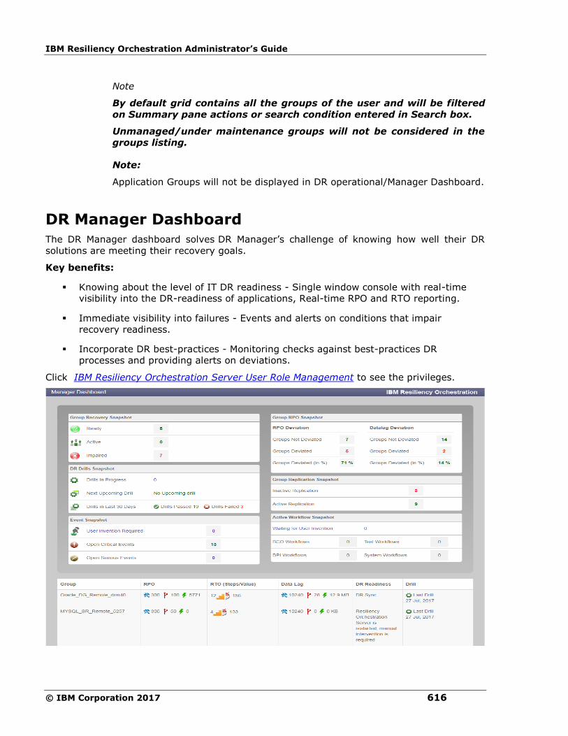
IBM Resiliency Orchestration Administrator’s Guide
© IBM Corporation 2017 616
Note
By default grid contains all the groups of the user and will be filtered
on Summary pane actions or search condition entered in Search box.
Unmanaged/under maintenance groups will not be considered in the
groups listing.
Note:
Application Groups will not be displayed in DR operational/Manager Dashboard.
DR Manager Dashboard
The DR Manager dashboard solves DR Manager’s challenge of knowing how well their DR
solutions are meeting their recovery goals.
Key benefits:
▪ Knowing about the level of IT DR readiness - Single window console with real-time
visibility into the DR-readiness of applications, Real-time RPO and RTO reporting.
▪ Immediate visibility into failures - Events and alerts on conditions that impair
recovery readiness.
▪ Incorporate DR best-practices - Monitoring checks against best-practices DR
processes and providing alerts on deviations.
Click IBM Resiliency Orchestration Server User Role Management to see the privileges.
Dashboards
617
There are 3 panes in the Dashboard page:
▪ Title pane
This pane displays the following:
▪ Last refreshed Time: This represents the last content refresh time with respect
to server time.
▪ Summary pane
It displays the following details:
Group Recovery Snapshot Status-Current Snapshot
In Group Recovery Snapshot status-Current SnapShot, the unmanaged/under
maintenance groups will not be considered.
This module displays number of Groups in the following states:
DR Ready
In this state the DR dataset and PR dataset are in a known replication state and
the replication status is one of the following:
• Replication is not occurring between them
• Normal mode of data replication and restoration is occurring.
• Normal mode of data replication and restoration failed for some reason
DR Active
The control of business is switched to DR site. PR dataset is down on PR site and
replication does not occur in this site
DR Impaired
This is the initial state of the Group. In this state, the DR dataset is not in a
known replication state. It has to be synchronized with the PR dataset for any DR
activity to take place. DR may be impaired due to issues during the transit to
Failover BCM.
Note:
Group list shows maximum of two groups for each state. When click on any state,the
Details pane filters the group with that state and lists the belonging groups.
DR Drills Snapshot
The module displays summary of Test exercises in the system as follows:
Number of Drills in progress.
Next Upcoming Drill with days left.
Drills in last 30 days.
It displays count of Drills passed and failed in the last 30 days. Failed drills
number is a link. On click of the link it will filter the bottom pane with failed
status.
Note:
IBM Resiliency Orchestration Administrator’s Guide
© IBM Corporation 2017 618
If test is not licensed, the window shows 'This feature is currently not licensed.
Refer license tab for details'.
Replication Snapshot
This module displays a graph showing Number of replications that are OK and are
Not OK.
The graph will have a line which denotes a scale showing total number of groups
considered for replication snapshot. It will start from 0 till the maximum number of
groups considered. A pointer will point to the number of groups that is Not OK. This
number is displayed above the pointer on the scale as highlighted in the above image.
Note:
It should be noted replication for unmanaged groups or groups under
maintenance will not be considered.
If replication is not licensed, the window shows 'This feature is currently not
licensed. Refer license tab for details'.
Group RPO Snapshot
It displays the RPO and Data Lag % deviation for the groups which are managed in
the form of angular graphs. The graph displays 7 deviation bands as follows:
Deviation > 100
100 > Deviation > 75
75 > Deviation > 50
50 > Deviation > 25
25 > Deviation > 0
Success [Green]
Greyed out band based on steps of 4 for number of groups
The colors of the deviation bands is as per the snapshot.
The scale has 5 divisions and it will be displayed based on number of groups. The
needle points to the no. of deviated groups.
Note:
Click on any part of the graph will filter bottom pane with deviated groups.
If recovery is not licensed, the window shows 'This feature is currently not
licensed. Refer license tab for details'.
Event Snapshot
It displays count of following Events :
User Intervention Required
Open Critical Event
Open Serious Event
Active Workflow Snapshot
Dashboards
619
It displays count for the following workflows in progress:
BCO Workflows
Test Workflows
BPI workflows
System workflows
Workflows waiting for user intervention
▪ Details pane
The Details pane (in the bottom) of the DR Manager Dashboard displays the following
for a list of Groups:
▪ Group Name
Note:
A search box is given for the user to search for the Group name.
▪ RPO
▪ RTO
▪ Data Lag
▪ DR Readiness with description
▪ Drill
▪ By default grid contains all the groups of the user and will be filtered on
Summary pane actions or search condition entered in Search box.
Note:
Unmanaged/under maintenance groups will not be considered in the groups listing.
Note:
Application Groups will not be displayed in DR operational/ Manager Dashboard.
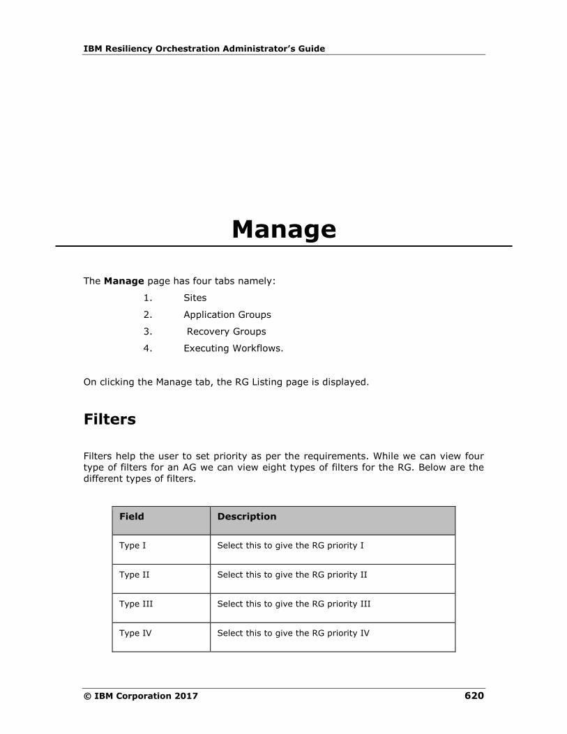
IBM Resiliency Orchestration Administrator’s Guide
© IBM Corporation 2017 620
Manage
The Manage page has four tabs namely:
1. Sites
2. Application Groups
3. Recovery Groups
4. Executing Workflows.
On clicking the Manage tab, the RG Listing page is displayed.
Filters
Filters help the user to set priority as per the requirements. While we can view four
type of filters for an AG we can view eight types of filters for the RG. Below are the
different types of filters.
Field Description
Type I Select this to give the RG priority I
Type II Select this to give the RG priority II
Type III Select this to give the RG priority III
Type IV Select this to give the RG priority IV

Manage
621
Field Description
DR Ready The RG is in this continuity state if:
▪ DR sync is in progress - NC workflow is
running
▪ DR sync is in progress- SLA is deviated by
12:23:45 - NC workflow is running but
RPO deviation is more than 100%
DR Active The RG is in this continuity state if:
▪ DR Resync is in Progress - RNC workflow
is running
▪ DR Active - Failover of the group is
successful
DR Impaired The RG is in this continuity state if:
▪ Switchover In Progress
▪ Switchback In Progress
▪ Failover In Progress
▪ Fallback In Progress
In Transit The RG is in this continuity state if:
▪ DR Init not started - After group is moved
to managed mode and NFC is not started
▪ DR Init is in progress - NFC workflow is
running
▪ DR Init is Aborted - NFC is aborted or
crashed
▪ DR Sync is Aborted - NC is aborted or
crashed
▪ DR Sync is Paused - Awaiting User Input
for Action Create File set - SLA is
deviated by 12:23:45 - NC is running but
awaiting
▪ DR Sync not started - NFC is successful
and group is moved to normal inactive

IBM Resiliency Orchestration Administrator’s Guide
© IBM Corporation 2017 622
Field Description
▪ DR Resync is not started - After SO is
successful and RNC workflow is not
started
▪ DR Resync is Aborted - RNC is aborted or
crashed
Note :
The filter attributes are dynamic to what is configured in group labels (admin > Go to
group labels).
Group Health
Displays the Group Health for each RG with the following colors:
Group status is changed to Red if there are any alertable critical events raised.
Group Status is changed to Amber if any alertable warning and serious events are raised.
Group status is green when there are no critical, serious and warning events open and only info events are present.
Group Status is changed to Grey when no monitoring information is available.
The number displayed in each color indicates the RGs in that group health state. The
group health graph changes based on the events that are raised for the group.
Sites
To view all the Sites, click Manage > Sites
The Sites page displays the Site listing, PR Sites, DR sites and the IBM Resiliency
Orchestration site information.
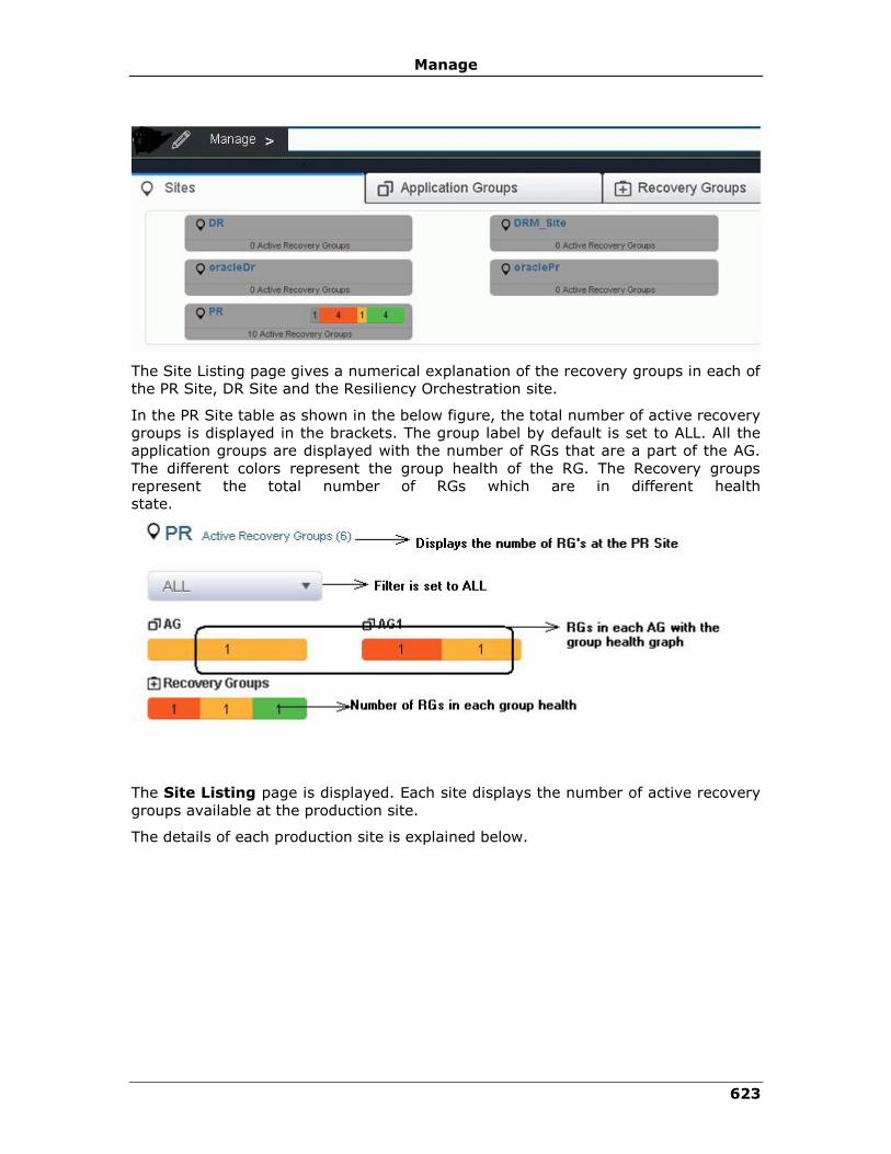
Manage
623
The Site Listing page gives a numerical explanation of the recovery groups in each of
the PR Site, DR Site and the Resiliency Orchestration site.
In the PR Site table as shown in the below figure, the total number of active recovery
groups is displayed in the brackets. The group label by default is set to ALL. All the
application groups are displayed with the number of RGs that are a part of the AG.
The different colors represent the group health of the RG. The Recovery groups
represent the total number of RGs which are in different health
state.
The Site Listing page is displayed. Each site displays the number of active recovery
groups available at the production site.
The details of each production site is explained below.
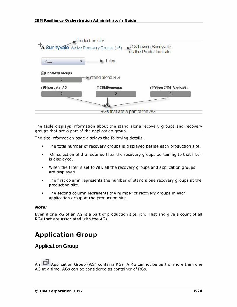
IBM Resiliency Orchestration Administrator’s Guide
© IBM Corporation 2017 624
The table displays information about the stand alone recovery groups and recovery
groups that are a part of the application group.
The site information page displays the following details:
▪ The total number of recovery groups is displayed beside each production site.
▪ On selection of the required filter the recovery groups pertaining to that filter
is displayed.
▪ When the filter is set to All, all the recovery groups and application groups
are displayed
▪ The first column represents the number of stand alone recovery groups at the
production site.
▪ The second column represents the number of recovery groups in each
application group at the production site.
Note:
Even if one RG of an AG is a part of production site, it will list and give a count of all
RGs that are associated with the AGs.
Application Group
Application Group
An Application Group (AG) contains RGs. A RG cannot be part of more than one
AG at a time. AGs can be considered as container of RGs.
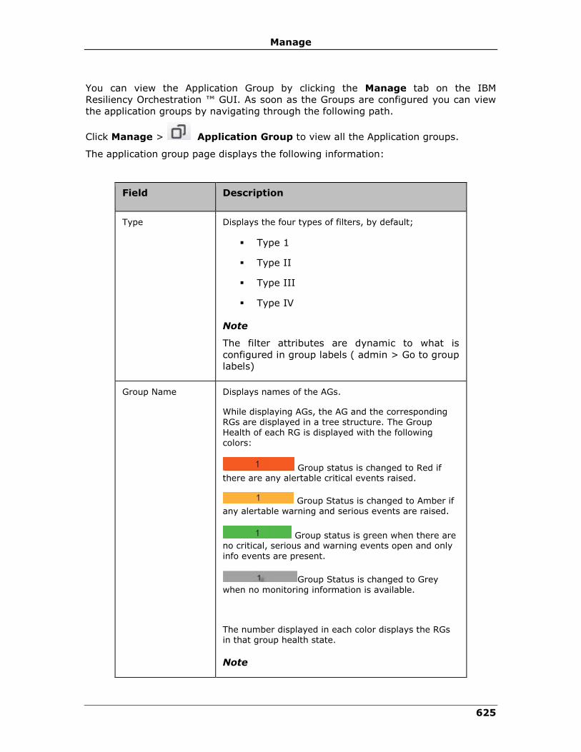
Manage
625
You can view the Application Group by clicking the Manage tab on the IBM
Resiliency Orchestration ™ GUI. As soon as the Groups are configured you can view
the application groups by navigating through the following path.
Click Manage > Application Group to view all the Application groups.
The application group page displays the following information:
Field Description
Type Displays the four types of filters, by default;
▪ Type 1
▪ Type II
▪ Type III
▪ Type IV
Note
The filter attributes are dynamic to what is
configured in group labels ( admin > Go to group
labels)
Group Name Displays names of the AGs.
While displaying AGs, the AG and the corresponding RGs are displayed in a tree structure. The Group Health of each RG is displayed with the following colors:
Group status is changed to Red if there are any alertable critical events raised.
Group Status is changed to Amber if any alertable warning and serious events are raised.
Group status is green when there are no critical, serious and warning events open and only
info events are present.
Group Status is changed to Grey when no monitoring information is available.
The number displayed in each color displays the RGs in that group health state.
Note
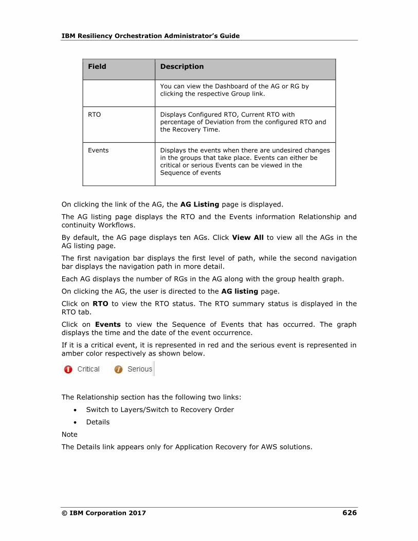
IBM Resiliency Orchestration Administrator’s Guide
© IBM Corporation 2017 626
Field Description
You can view the Dashboard of the AG or RG by clicking the respective Group link.
RTO Displays Configured RTO, Current RTO with percentage of Deviation from the configured RTO and the Recovery Time.
Events Displays the events when there are undesired changes in the groups that take place. Events can either be critical or serious Events can be viewed in the
Sequence of events
On clicking the link of the AG, the AG Listing page is displayed.
The AG listing page displays the RTO and the Events information Relationship and
continuity Workflows.
By default, the AG page displays ten AGs. Click View All to view all the AGs in the
AG listing page.
The first navigation bar displays the first level of path, while the second navigation
bar displays the navigation path in more detail.
Each AG displays the number of RGs in the AG along with the group health graph.
On clicking the AG, the user is directed to the AG listing page.
Click on RTO to view the RTO status. The RTO summary status is displayed in the
RTO tab.
Click on Events to view the Sequence of Events that has occurred. The graph
displays the time and the date of the event occurrence.
If it is a critical event, it is represented in red and the serious event is represented in
amber color respectively as shown below.
The Relationship section has the following two links:
• Switch to Layers/Switch to Recovery Order
• Details
Note
The Details link appears only for Application Recovery for AWS solutions.
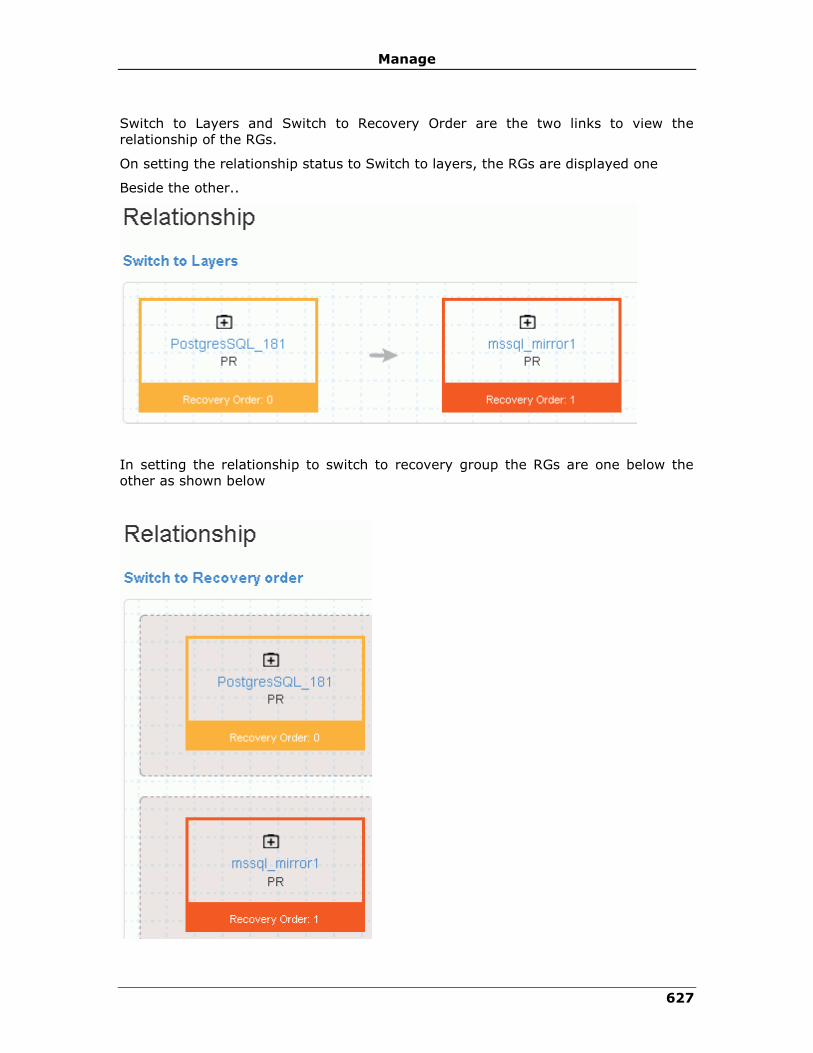
Manage
627
Switch to Layers and Switch to Recovery Order are the two links to view the
relationship of the RGs.
On setting the relationship status to Switch to layers, the RGs are displayed one
Beside the other..
In setting the relationship to switch to recovery group the RGs are one below the
other as shown below
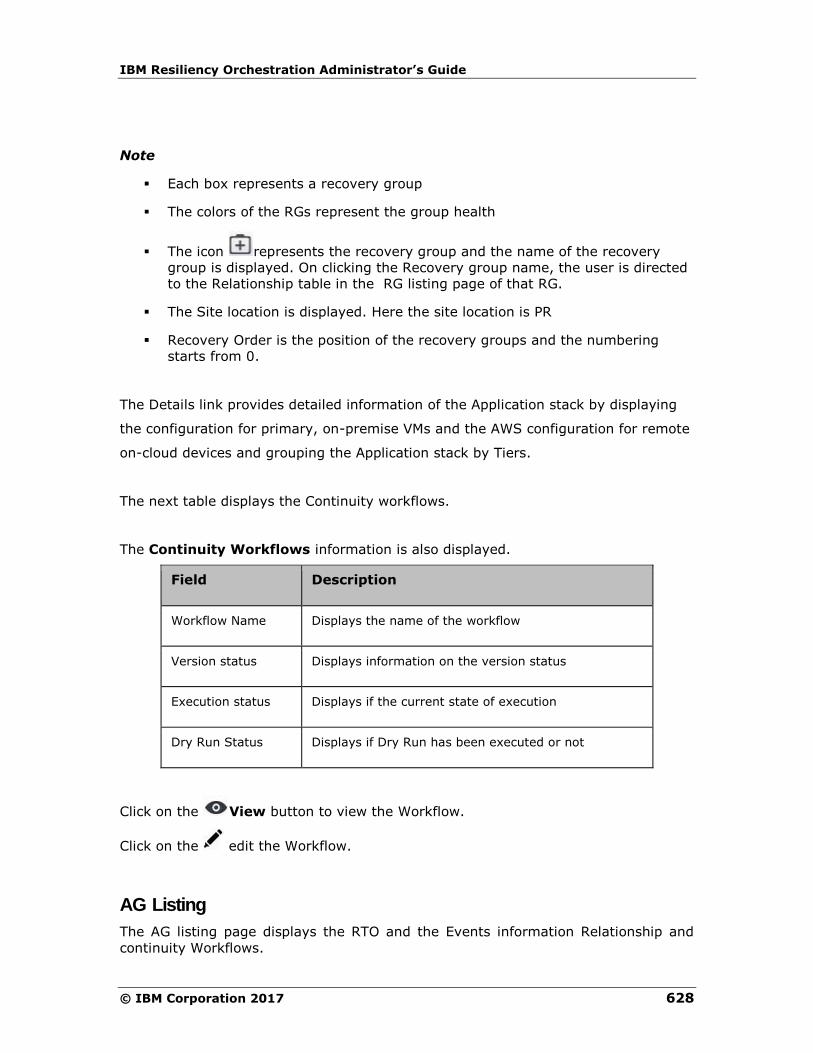
IBM Resiliency Orchestration Administrator’s Guide
© IBM Corporation 2017 628
Note
▪ Each box represents a recovery group
▪ The colors of the RGs represent the group health
▪ The icon represents the recovery group and the name of the recovery
group is displayed. On clicking the Recovery group name, the user is directed
to the Relationship table in the RG listing page of that RG.
▪ The Site location is displayed. Here the site location is PR
▪ Recovery Order is the position of the recovery groups and the numbering
starts from 0.
The Details link provides detailed information of the Application stack by displaying
the configuration for primary, on-premise VMs and the AWS configuration for remote
on-cloud devices and grouping the Application stack by Tiers.
The next table displays the Continuity workflows.
The Continuity Workflows information is also displayed.
Field Description
Workflow Name Displays the name of the workflow
Version status Displays information on the version status
Execution status Displays if the current state of execution
Dry Run Status Displays if Dry Run has been executed or not
Click on the View button to view the Workflow.
Click on the edit the Workflow.
AG Listing
The AG listing page displays the RTO and the Events information Relationship and
continuity Workflows.

Manage
629
By default, the AG page displays ten AGs. Click View All to view all the AGs in the
AG listing page.
The search bar is automatically backfilled with the search criteria based on the page
context. The breadcrumbs help navigate to the desired page.
Each AG displays the number of RGs in the AG along with the group health graph.
On clicking the AG, the user is directed to the AG Details page.
AG Details
Click Manage> AG Listing page > AG details.
Click RTO to view the RTO status. The RTO summary status is displayed in the RTO
tab.
Click on Events to view the Sequence of Events that has occurred. The graph
displays the time and the date of the event occurrence.
If it is a critical event, it is represented in red and the serious event is represented in
amber color respectively as shown below.
To view the relationship of RGs within the AG click Relationship.
The next table displays the Continuity Workflows.
Relationship
The Relationship between the RGs within the AG is displayed. There are two ways
of representing this; Layers and Recovery Order.
The layers will represent the relationship in teh form of layers and the recovery order
will represent the relationship in the order in which they will be recovered. Layers
showcase the serial order and recovery order represents the parallel execution of the
RGs.

IBM Resiliency Orchestration Administrator’s Guide
© IBM Corporation 2017 630
In setting the relationship to switch to recovery group the RGs are one below the
other as shown in the following figure.
▪ Each box represents a recovery group.
▪ The colors of the RGs represent the group health
Manage
631
▪ The icon represents the recovery group and the name of the recovery
group is displayed
▪ The Site location is displayed. Here the site location is PR.
Recovery Group
Recovery Group
Click Manage > Recovery Group to view the Recovery groups. The Group
Health meter in the RG page displays the number of recovery groups under each
state. The RGs can be classified under these are four colors which display the health
of the group.
The group health graph displays the recovery groups in each group health state. On
hovering over the graph the percentage of each group health is displayed.
The filter by default is set as Type 1. The RG listing page displays ten recovery
groups, on clicking View All, all the recovery groups are displayed. For each
recovery group, the following information is displayed.
Field Description
Group Name Displays names of the RGs
RPO Displays the configured RPO (in minutes) of the Group.
Note
If the configured RPO and the current RPO for the Group has crossed the threshold value you can view the deviation in red (or orange). If the deviation is within the threshold value, the deviation is represented in green.
RTO
Displays the RTO status (in minutes) for the Group.
The current RTO and the configured RTO is
displayed. If there is any deviation, the percentage is displayed.
Replication Displays when the last replication has occurred
Validation Displays information if the validation has been

IBM Resiliency Orchestration Administrator’s Guide
© IBM Corporation 2017 632
executed.
There are eight types of filters for a RG. See Filters.
On clicking the Recovery Group, the RG Listing page is displayed.
RG Listing
Click Manage> Recovery Groups. The group health of each recovery group is
displayed beside the recovery group.
The RG Listing page is displayed. The RG Listing page displays the following details
of each recovery group.
Note:
For VM protection solutions,the RTO tab is not displayed. However the RG Group
listing page displays RTO as Workflow not published.
Field Description
Group Name Displays names of the RG
RPO Displays the configured RPO (in minutes) of the Group.
Note
If the configured RPO and the current RPO for the Group has crossed the threshold value you can view the deviation in red (or orange). If the deviation is within the threshold value, the deviation is represented in green. For more information se
RTO
Displays the RTO status (in minutes) for the Group.
The current RTO and the configured RTO is
displayed. If there is any deviation, the percentage is displayed. For more information see Viewing RTO Details
Replication Displays when the last replication occurred
Validation Displays information if the validation has been executed.

Manage
633
Click on the group name to view the RG Details page.
RG Details
To view the details of each RG, click Manage> Recovery Groups > on the RG
name.
Field Description
RTO Displays the RTO status (in minutes) for the Group.
The current RTO and the configured RTO is
displayed. If there is any deviation, the percentage is displayed.
RPO Displays the configured RPO (in minutes) of the Group.
Note
If the configured RPO and the current RPO for the Group has crossed the threshold value you can view the deviation in red (or orange). If the deviation is
within the threshold value, the deviation is represented in green.
Replication Displays when the last replication occurred
Events Displays the events. For more information click Sequence of Events
Validation Displays information if the validation has been executed.
Relationship in RG
The Relationship image displays the relationship between the RGs within the AG in
the PR and the DR site.
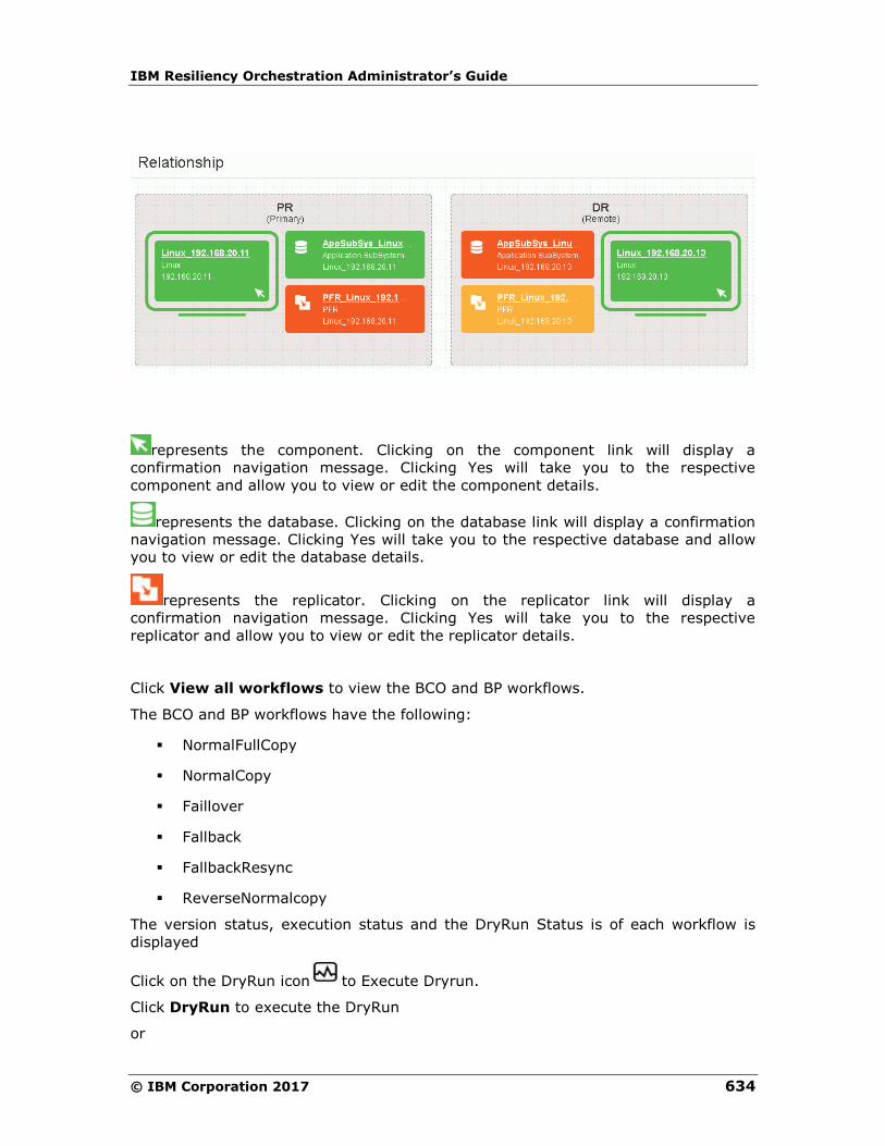
IBM Resiliency Orchestration Administrator’s Guide
© IBM Corporation 2017 634
represents the component. Clicking on the component link will display a
confirmation navigation message. Clicking Yes will take you to the respective
component and allow you to view or edit the component details.
represents the database. Clicking on the database link will display a confirmation
navigation message. Clicking Yes will take you to the respective database and allow
you to view or edit the database details.
represents the replicator. Clicking on the replicator link will display a
confirmation navigation message. Clicking Yes will take you to the respective
replicator and allow you to view or edit the replicator details.
Click View all workflows to view the BCO and BP workflows.
The BCO and BP workflows have the following:
▪ NormalFullCopy
▪ NormalCopy
▪ Faillover
▪ Fallback
▪ FallbackResync
▪ ReverseNormalcopy
The version status, execution status and the DryRun Status is of each workflow is
displayed
Click on the DryRun icon to Execute Dryrun.
Click DryRun to execute the DryRun
or
Manage
635
Click Cancel to cancel the DryRun execution.
Continuity Workflows
To view the business process workflows:
1. Click Manage> AG/ RG > Application Group / Recovery
Group Name.
2. The AG Details / RG Details page is displayed.
3. Click View All Workflows if it is a RG.
▪ Click the BCO tab, all BCO workflows are displayed for the RG
▪ Click the BP tab, all BP workflows are displayed for the RG.
The following details are displayed:
Field Description
Workflow Name Displays the name of the workflow.
Displays the group name for which you want to add the business process.
Version status Displays the group name for which you want to add the business process.
Execution status Displays information if the execution was success, crashed aborted or is awaiting input.
Dry Run Status Displays information if the workflow was a success, crashed, not executed or failed
▪ Click to execute the workflow.
▪ Click to DryRun the workflow
▪ Click to schedule the workflow execution.
▪ Click to preview the workflow.
▪ Click to edit the workflow.

IBM Resiliency Orchestration Administrator’s Guide
© IBM Corporation 2017 636
▪ Click to delete the workflow.
▪ Click Create New to create a new workflow.
Note
▪ If the group is in switchover or switchback, then the current DR state of the
group does not permit any continuity operations.
▪ To change the state of the group, go to Discover > groups page.
To view the execution history and the version history, click on the workflow name.
The Execution History displays the following information:
Field Description
Date Displays the date of execution
Time Taken Displays the time taken in seconds for execution
status Workflow execution status
Version Displays the version number
The Version History displays the following information:
Field Description
Version Displays the version number
Created On Displays the workflow created time
Created By Displays the User name
Executing Workflows
Executing Workflow
You can view the details of workflow which is currently executing along with the
details of each action of the workflow.
Manage
637
To view the Workflow, do the following:
1. Click Manage > Executing Workflows tab on the
navigation bar to view the RG listing page.
2. For the desired Group, select the Workflow link from the
WORKFLOW DETAILS column. The Workflow Execution page
appears.
3. Select the RG/AG from the drop-down list filter. If the selected
group is RG, then the eight types of filters are displayed and the if it is
an AG, then only four types of filters are displayed namely:
▪ Type I
▪ Type II
▪ Type III
▪ Type IV
1 If the selected group is a RG, only then the workflow drop-down list is displayed.
Select from the drop-down list.
▪ BCO
▪ BP
▪ Policy
▪ System Workflow
▪ All
The following details are displayed:
Field Description
Group Name Displays the name of the workflow.
Workflow name and Version
Displays the Workflow name and its present version.
Start Time Displays start time of the Workflow.
Time Elapsed Displays the time elapsed from the process of initiation to completion of the Workflow.
Status and results of RALS
Displays the status of the Workflow and also the count reflect number of completed actions versus total actions.
On clicking the Group name, the user is directed to the RG details page or the AG
details page of that group.
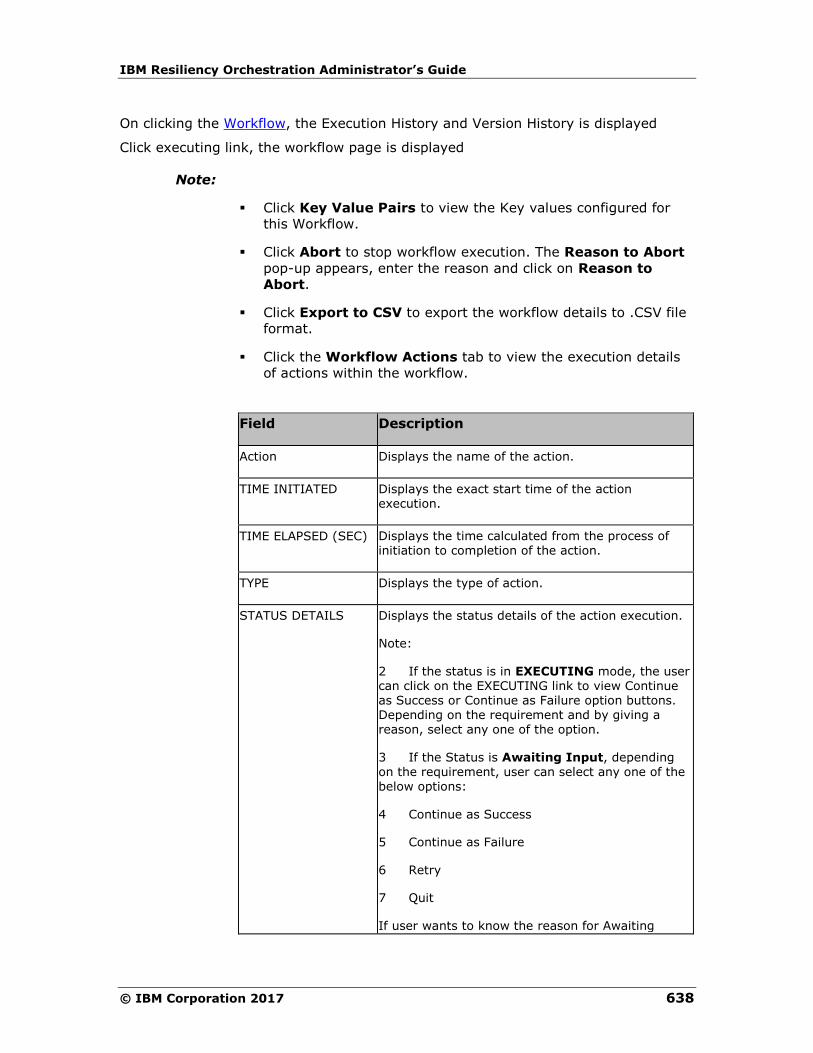
IBM Resiliency Orchestration Administrator’s Guide
© IBM Corporation 2017 638
On clicking the Workflow, the Execution History and Version History is displayed
Click executing link, the workflow page is displayed
Note:
▪ Click Key Value Pairs to view the Key values configured for
this Workflow.
▪ Click Abort to stop workflow execution. The Reason to Abort
pop-up appears, enter the reason and click on Reason to
Abort.
▪ Click Export to CSV to export the workflow details to .CSV file
format.
▪ Click the Workflow Actions tab to view the execution details
of actions within the workflow.
Field Description
Action Displays the name of the action.
TIME INITIATED Displays the exact start time of the action execution.
TIME ELAPSED (SEC) Displays the time calculated from the process of initiation to completion of the action.
TYPE Displays the type of action.
STATUS DETAILS Displays the status details of the action execution.
Note:
2 If the status is in EXECUTING mode, the user can click on the EXECUTING link to view Continue as Success or Continue as Failure option buttons. Depending on the requirement and by giving a reason, select any one of the option.
3 If the Status is Awaiting Input, depending on the requirement, user can select any one of the
below options:
4 Continue as Success
5 Continue as Failure
6 Retry
7 Quit
If user wants to know the reason for Awaiting
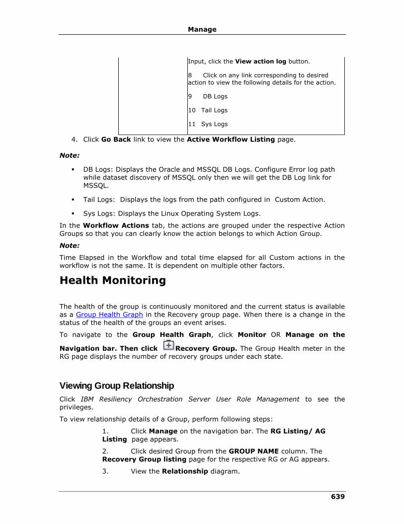
Manage
639
Input, click the View action log button.
8 Click on any link corresponding to desired action to view the following details for the action.
9 DB Logs
10 Tail Logs
11 Sys Logs
4. Click Go Back link to view the Active Workflow Listing page.
Note:
▪ DB Logs: Displays the Oracle and MSSQL DB Logs. Configure Error log path
while dataset discovery of MSSQL only then we will get the DB Log link for
MSSQL.
▪ Tail Logs: Displays the logs from the path configured in Custom Action.
▪ Sys Logs: Displays the Linux Operating System Logs.
In the Workflow Actions tab, the actions are grouped under the respective Action
Groups so that you can clearly know the action belongs to which Action Group.
Note:
Time Elapsed in the Workflow and total time elapsed for all Custom actions in the
workflow is not the same. It is dependent on multiple other factors.
Health Monitoring
The health of the group is continuously monitored and the current status is available
as a Group Health Graph in the Recovery group page. When there is a change in the
status of the health of the groups an event arises.
To navigate to the Group Health Graph, click Monitor OR Manage on the
Navigation bar. Then click Recovery Group. The Group Health meter in the
RG page displays the number of recovery groups under each state.
Viewing Group Relationship
Click IBM Resiliency Orchestration Server User Role Management to see the
privileges.
To view relationship details of a Group, perform following steps:
1. Click Manage on the navigation bar. The RG Listing/ AG
Listing page appears.
2. Click desired Group from the GROUP NAME column. The
Recovery Group listing page for the respective RG or AG appears.
3. View the Relationship diagram.
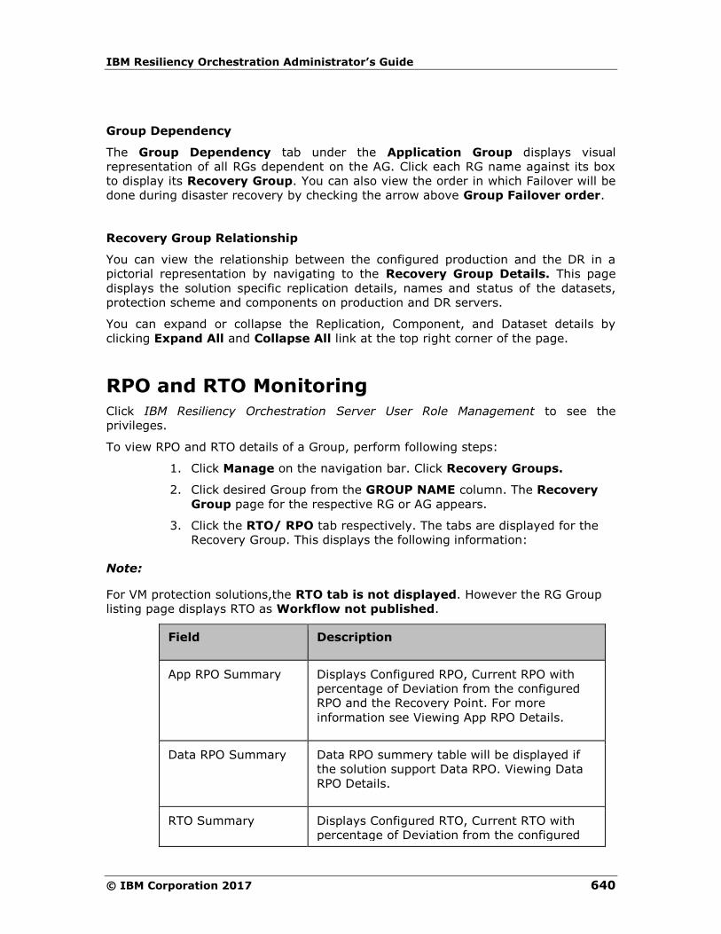
IBM Resiliency Orchestration Administrator’s Guide
© IBM Corporation 2017 640
Group Dependency
The Group Dependency tab under the Application Group displays visual
representation of all RGs dependent on the AG. Click each RG name against its box
to display its Recovery Group. You can also view the order in which Failover will be
done during disaster recovery by checking the arrow above Group Failover order.
Recovery Group Relationship
You can view the relationship between the configured production and the DR in a
pictorial representation by navigating to the Recovery Group Details. This page
displays the solution specific replication details, names and status of the datasets,
protection scheme and components on production and DR servers.
You can expand or collapse the Replication, Component, and Dataset details by
clicking Expand All and Collapse All link at the top right corner of the page.
RPO and RTO Monitoring
Click IBM Resiliency Orchestration Server User Role Management to see the
privileges.
To view RPO and RTO details of a Group, perform following steps:
1. Click Manage on the navigation bar. Click Recovery Groups.
2. Click desired Group from the GROUP NAME column. The Recovery
Group page for the respective RG or AG appears.
3. Click the RTO/ RPO tab respectively. The tabs are displayed for the
Recovery Group. This displays the following information:
Note:
For VM protection solutions,the RTO tab is not displayed. However the RG Group
listing page displays RTO as Workflow not published.
Field Description
App RPO Summary Displays Configured RPO, Current RPO with
percentage of Deviation from the configured
RPO and the Recovery Point. For more
information see Viewing App RPO Details.
Data RPO Summary Data RPO summery table will be displayed if
the solution support Data RPO. Viewing Data
RPO Details.
RTO Summary Displays Configured RTO, Current RTO with
percentage of Deviation from the configured

Manage
641
RTO and the Recovery Time. For more
information see Viewing RTO Details
RTO Breakup Displays the name of the Recovery Step
executed during the recovery process along
with the Expected Completion Time in
seconds.
Monitoring Replication
You can view the detailed Replication List by clicking Manage > Recovery Groups
and the Recovery Groups Listing page appears.
Select any Group name and click Group Replication tab.
In the Replication page you can monitor the replication process for each group by
viewing the detailed replication status of the group and the protection scheme
associated with the Group. Storage related information of the monitored RG and
information about data consistency i.e whether the DR site is in sync with the
Production without respect to data replication are also displayed. For example for a
Group configured under the SRDF Protection Scheme you can view the IDs of the
source and target symmetric units.
The Replication tab displays the Data log and the last updated time the files have
been replicated.
Field Description
Data Lag Displays the data lag information for the RG
Last Updated Displays the time when the RG was last updated
Click Stop Replication to stop the replication.
Click Start Replication to start the replication.
Click Refresh Details to refresh the replication page.
The replication details are displayed in the table:
Field Description

IBM Resiliency Orchestration Administrator’s Guide
© IBM Corporation 2017 642
Protection Displays the replication type
Replication status Displays the status of the replication, Active Inactive and Unknown
Primary-Remote service
Displays the PR and DR information
Note
This table consists of basic information for all groups. Additional information will be
displayed, depending on the Replication Type.
Viewing Recovery Group Replication Details
To view the DR Solution specific replication details of the RG, perform the following
steps:
1 Click Manage> Recovery Groups. The RG Listing Page appears.
2 Click Group Name in the RG Listing Page.
3 Click the Replication tab.
4 The Replication Details page is displayed that lists the DR Solution specific
replication details. The Replication tab is displayed only for that Recovery Group.
You can monitor the current status of the replication between the production and DR.
For example, in the case of SRDF protection mechanism, the details of the protection
mechanism, the specific device names, the status of the WAN link connection
between the two RDF devices the mode of replication i.e synchronous or
asynchronous and the number of invalid tracks are displayed.
Click Stop Replication to stop the replication process.
Click the Refresh Details to refresh the information.
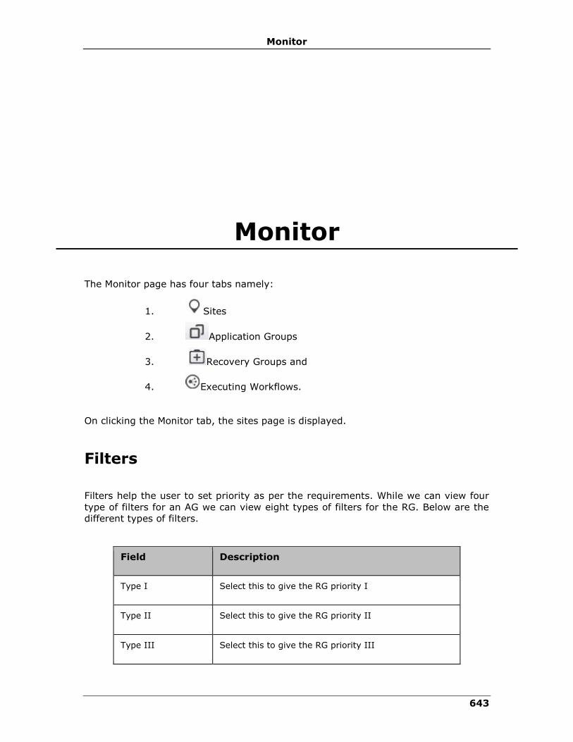
Monitor
643
Monitor
The Monitor page has four tabs namely:
1. Sites
2. Application Groups
3. Recovery Groups and
4. Executing Workflows.
On clicking the Monitor tab, the sites page is displayed.
Filters
Filters help the user to set priority as per the requirements. While we can view four
type of filters for an AG we can view eight types of filters for the RG. Below are the
different types of filters.
Field Description
Type I Select this to give the RG priority I
Type II Select this to give the RG priority II
Type III Select this to give the RG priority III

IBM Resiliency Orchestration Administrator’s Guide
© IBM Corporation 2017 644
Field Description
Type IV Select this to give the RG priority IV
DR Ready The RG is in this continuity state if:
▪ DR sync is in progress - NC workflow is
running
▪ DR sync is in progress- SLA is deviated by
12:23:45 - NC workflow is running but
RPO deviation is more than 100%
DR Active The RG is in this continuity state if:
▪ DR Resync is in Progress - RNC workflow
is running
▪ DR Active - Failover of the group is
successful
DR Impaired The RG is in this continuity state if:
▪ Switchover In Progress
▪ Switchback In Progress
▪ Failover In Progress
▪ Fallback In Progress
In Transit The RG is in this continuity state if:
▪ DR Init not started - After group is moved
to managed mode and NFC is not started
▪ DR Init is in progress - NFC workflow is
running
▪ DR Init is Aborted - NFC is aborted or
crashed
▪ DR Sync is Aborted - NC is aborted or
crashed
▪ DR Sync is Paused - Awaiting User Input
for Action Create File set - SLA is
deviated by 12:23:45 - NC is running but
awaiting

Monitor
645
Field Description
▪ DR Sync not started - NFC is successful
and group is moved to normal inactive
▪ DR Resync is not started - After SO is
successful and RNC workflow is not
started
▪ DR Resync is Aborted - RNC is aborted or
crashed
Note :
The filter attributes are dynamic to what is configured in group labels (admin > Go to
group labels).
Group Health
Displays the Group Health for each RG with the following colors:
Group status is changed to Red if there are any alertable critical events raised.
Group Status is changed to Amber if any alertable warning and serious events are raised.
Group status is green when there are no critical, serious and warning events open and only info events are present.
Group Status is changed to Grey when no monitoring information is available.
The number displayed in each color indicates the RGs in that group health state. The
group health graph changes based on the events that are raised for the group.
Sites
To view all the Sites, click Monitor > Sites
The Sites page displays the Site listing, PR Sites, DR sites and the IBM Resiliency
Orchestration site information.
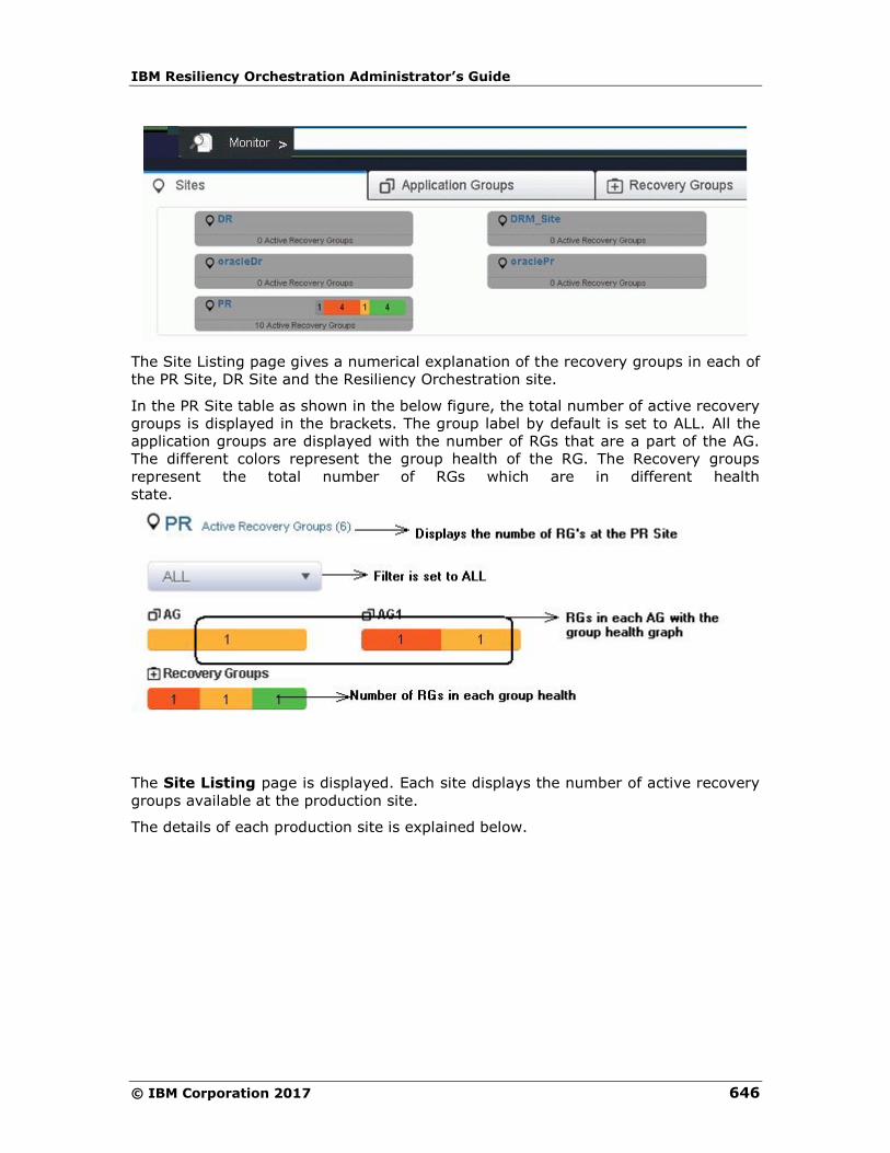
IBM Resiliency Orchestration Administrator’s Guide
© IBM Corporation 2017 646
The Site Listing page gives a numerical explanation of the recovery groups in each of
the PR Site, DR Site and the Resiliency Orchestration site.
In the PR Site table as shown in the below figure, the total number of active recovery
groups is displayed in the brackets. The group label by default is set to ALL. All the
application groups are displayed with the number of RGs that are a part of the AG.
The different colors represent the group health of the RG. The Recovery groups
represent the total number of RGs which are in different health
state.
The Site Listing page is displayed. Each site displays the number of active recovery
groups available at the production site.
The details of each production site is explained below.
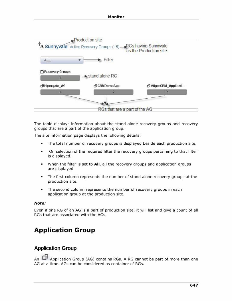
Monitor
647
The table displays information about the stand alone recovery groups and recovery
groups that are a part of the application group.
The site information page displays the following details:
▪ The total number of recovery groups is displayed beside each production site.
▪ On selection of the required filter the recovery groups pertaining to that filter
is displayed.
▪ When the filter is set to All, all the recovery groups and application groups
are displayed
▪ The first column represents the number of stand alone recovery groups at the
production site.
▪ The second column represents the number of recovery groups in each
application group at the production site.
Note:
Even if one RG of an AG is a part of production site, it will list and give a count of all
RGs that are associated with the AGs.
Application Group
Application Group
An Application Group (AG) contains RGs. A RG cannot be part of more than one
AG at a time. AGs can be considered as container of RGs.

IBM Resiliency Orchestration Administrator’s Guide
© IBM Corporation 2017 648
You can view the Application Group by clicking the Monitor tab on the IBM
Resiliency Orchestration ™ GUI. As soon as the Groups are configured you can view
the application groups by navigating through the following path.
Click Monitor > Application Group to view all the Application groups.
The application group page displays the following information:
Field Description
Type Displays the four types of filters, by default;
▪ Type 1
▪ Type II
▪ Type III
▪ Type IV
Note
The filter attributes are dynamic to what is
configured in group labels ( admin > Go to group
labels)
Group Name Displays names of the AGs.
While displaying AGs, the AG and the corresponding RGs are displayed in a tree structure. The Group Health of each RG is displayed with the following colors:
Group status is changed to Red if there are any alertable critical events raised.
Group Status is changed to Amber if any alertable warning and serious events are raised.
Group status is green when there are no critical, serious and warning events open and only
info events are present.
Group Status is changed to Grey when no monitoring information is available.
The number displayed in each color displays the RGs in that group health state.
Note
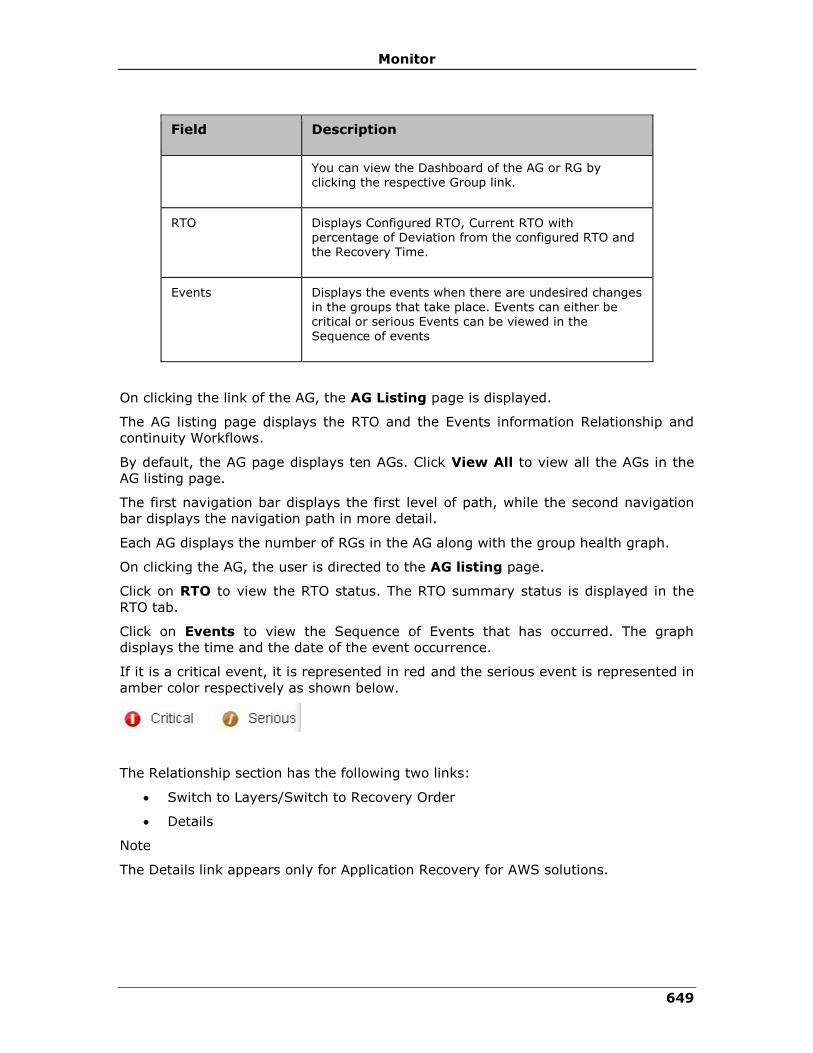
Monitor
649
Field Description
You can view the Dashboard of the AG or RG by clicking the respective Group link.
RTO Displays Configured RTO, Current RTO with percentage of Deviation from the configured RTO and the Recovery Time.
Events Displays the events when there are undesired changes in the groups that take place. Events can either be critical or serious Events can be viewed in the
Sequence of events
On clicking the link of the AG, the AG Listing page is displayed.
The AG listing page displays the RTO and the Events information Relationship and
continuity Workflows.
By default, the AG page displays ten AGs. Click View All to view all the AGs in the
AG listing page.
The first navigation bar displays the first level of path, while the second navigation
bar displays the navigation path in more detail.
Each AG displays the number of RGs in the AG along with the group health graph.
On clicking the AG, the user is directed to the AG listing page.
Click on RTO to view the RTO status. The RTO summary status is displayed in the
RTO tab.
Click on Events to view the Sequence of Events that has occurred. The graph
displays the time and the date of the event occurrence.
If it is a critical event, it is represented in red and the serious event is represented in
amber color respectively as shown below.
The Relationship section has the following two links:
• Switch to Layers/Switch to Recovery Order
• Details
Note
The Details link appears only for Application Recovery for AWS solutions.
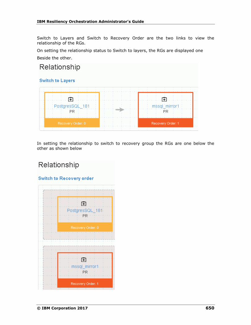
IBM Resiliency Orchestration Administrator’s Guide
© IBM Corporation 2017 650
Switch to Layers and Switch to Recovery Order are the two links to view the
relationship of the RGs.
On setting the relationship status to Switch to layers, the RGs are displayed one
Beside the other.
In setting the relationship to switch to recovery group the RGs are one below the
other as shown below

Monitor
651
Note
▪ Each box represents a recovery group
▪ The colors of the RGs represent the group health
▪ The icon represents the recovery group and the name of the recovery
group is displayed. On clicking the Recovery group name, the user is directed
to the Relationship table in the RG listing page of that RG.
▪ The Site location is displayed. Here the site location is PR
▪ Recovery Order is the position of the recovery groups and the numbering
starts from 0.
The Details link provides detailed information of the Application stack by displaying
the configuration for primary, on-premise VMs and the AWS configuration for remote
on-cloud devices and grouping the Application stack by Tiers.
The next table displays the Continuity workflows.
The Continuity Workflows information is also displayed.
Field Description
Workflow Name Displays the name of the workflow
Version status Displays information on the version status
Execution status Displays if the current state of execution
Dry Run Status Displays if Dry Run has been executed or not
Click on the View button to view the Workflow.
Note:
The user cannot edit the workflow in the View workflow page when navigating from
Monitor page.
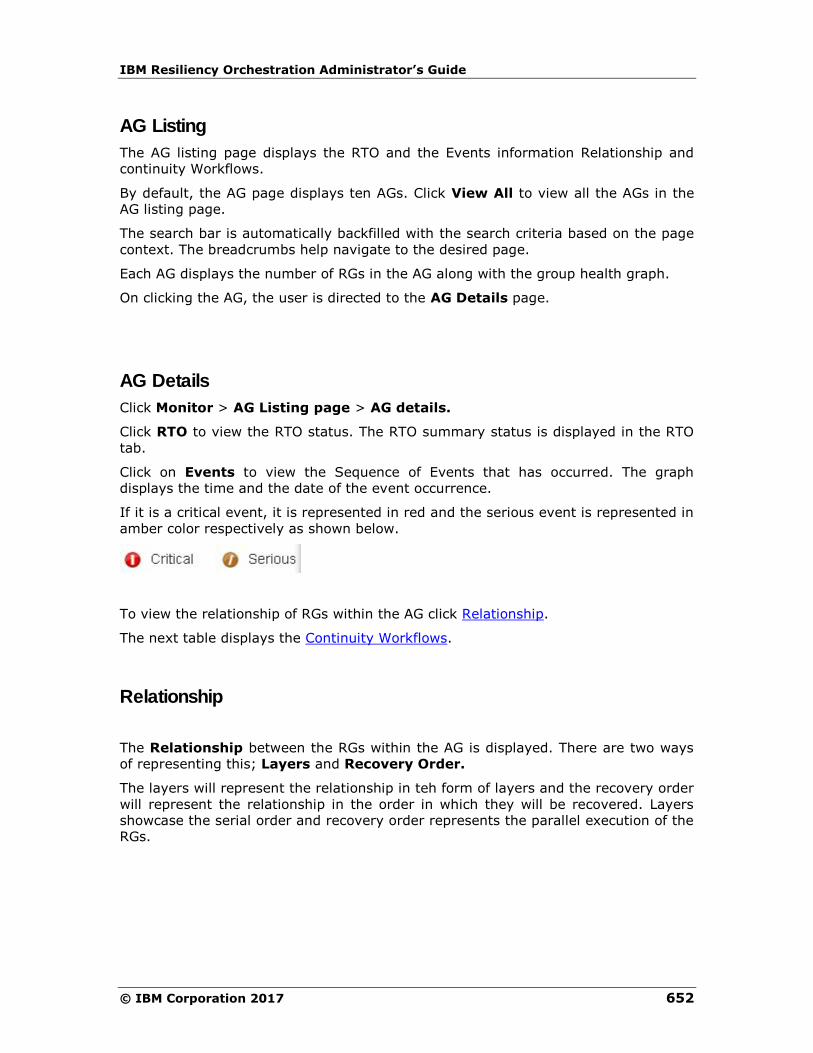
IBM Resiliency Orchestration Administrator’s Guide
© IBM Corporation 2017 652
AG Listing
The AG listing page displays the RTO and the Events information Relationship and
continuity Workflows.
By default, the AG page displays ten AGs. Click View All to view all the AGs in the
AG listing page.
The search bar is automatically backfilled with the search criteria based on the page
context. The breadcrumbs help navigate to the desired page.
Each AG displays the number of RGs in the AG along with the group health graph.
On clicking the AG, the user is directed to the AG Details page.
AG Details
Click Monitor > AG Listing page > AG details.
Click RTO to view the RTO status. The RTO summary status is displayed in the RTO
tab.
Click on Events to view the Sequence of Events that has occurred. The graph
displays the time and the date of the event occurrence.
If it is a critical event, it is represented in red and the serious event is represented in
amber color respectively as shown below.
To view the relationship of RGs within the AG click Relationship.
The next table displays the Continuity Workflows.
Relationship
The Relationship between the RGs within the AG is displayed. There are two ways
of representing this; Layers and Recovery Order.
The layers will represent the relationship in teh form of layers and the recovery order
will represent the relationship in the order in which they will be recovered. Layers
showcase the serial order and recovery order represents the parallel execution of the
RGs.
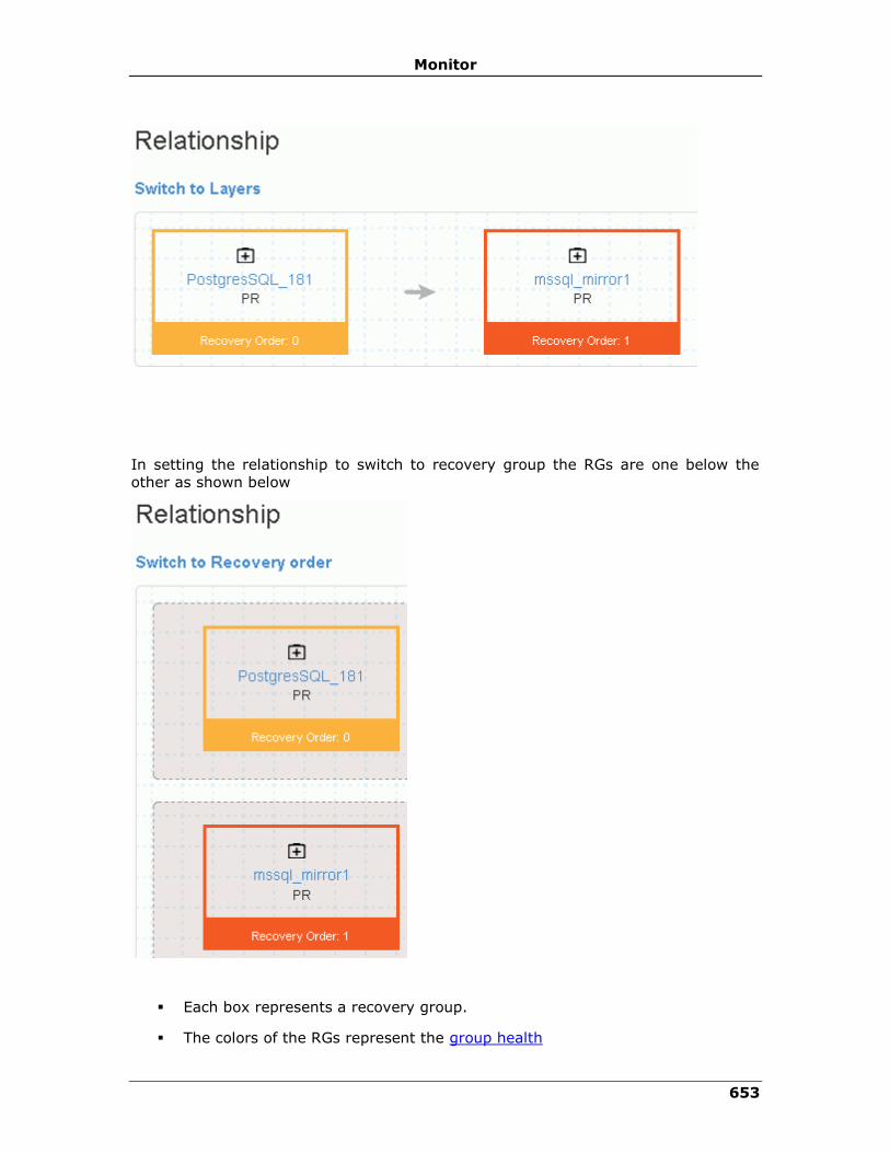
Monitor
653
In setting the relationship to switch to recovery group the RGs are one below the
other as shown below
▪ Each box represents a recovery group.
▪ The colors of the RGs represent the group health

IBM Resiliency Orchestration Administrator’s Guide
© IBM Corporation 2017 654
▪ The icon represents the recovery group and the name of the recovery
group is displayed
▪ The Site location is displayed. Here the site location is PR.
Recovery Group
Recovery Group
Click Monitor > Recovery Group to view the Recovery groups. The Group
Health meter in the RG page displays the number of recovery groups under each
state. The RGs can be classified under these are four colors which display the health
of the group.
The group health graph displays the recovery groups in each group health state. On
hovering over the graph the percentage of each group health is displayed.
The filter by default is set as Type 1. The RG listing page displays ten recovery
groups, on clicking View All, all the recovery groups are displayed. For each
recovery group, the following information is displayed.
Field Description
Group Name Displays names of the RGs
RPO Displays the configured RPO (in minutes) of the Group.
Note
If the configured RPO and the current RPO for the Group has crossed the threshold value you can view the deviation in red (or orange). If the deviation is within the threshold value, the deviation is represented in green.
RTO
Displays the RTO status (in minutes) for the Group.
The current RTO and the configured RTO is
displayed. If there is any deviation, the percentage is displayed.
Replication Displays when the last replication has occurred
Validation Displays information if the validation has been

Monitor
655
executed.
There are eight types of filters for a RG. See Filters.
On clicking the Recovery Group, the RG Listing page is displayed.
RG Listing
Click Monitor> Recovery Groups. The group health of each recovery group is
displayed beside the recovery group.
The RG Listing page is displayed. The RG Listing page displays the following details
of each recovery group.
Note:
For VM protection solutions,the RTO tab is not displayed. However the RG Group
listing page displays RTO as Workflow not published.
Field Description
Group Name Displays names of the RG
RPO Displays the configured RPO (in minutes) of the Group.
Note
If the configured RPO and the current RPO for the Group has crossed the threshold value you can view the deviation in red (or orange). If the deviation is within the threshold value, the deviation is represented in green. For more information se
RTO
Displays the RTO status (in minutes) for the Group.
The current RTO and the configured RTO is
displayed. If there is any deviation, the percentage is displayed. For more information see Viewing RTO Details
Replication Displays when the last replication occurred
Validation Displays information if the validation has been executed.

IBM Resiliency Orchestration Administrator’s Guide
© IBM Corporation 2017 656
Click on the group name to view the RG Details page.
RG Details
To view the details of each RG, click Monitor> Recovery Groups > on the RG
name.
Field Description
RTO Displays the RTO status (in minutes) for the Group.
The current RTO and the configured RTO is
displayed. If there is any deviation, the percentage is displayed.
RPO Displays the configured RPO (in minutes) of the Group.
Note
If the configured RPO and the current RPO for the Group has crossed the threshold value you can view the deviation in red (or orange). If the deviation is within the threshold value, the deviation is
represented in green.
Replication Displays when the last replication occurred
Events Displays the events. For more information click Sequence of Events
Validation Displays information if the validation has been executed.
Relationship in RG
The Relationship image displays the relationship between the RGs within the AG in
the PR and the DR site.
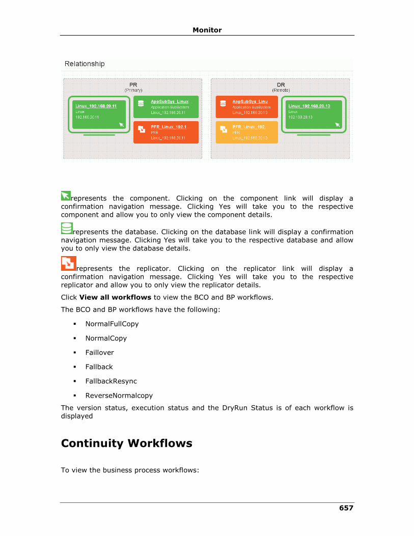
Monitor
657
represents the component. Clicking on the component link will display a
confirmation navigation message. Clicking Yes will take you to the respective
component and allow you to only view the component details.
represents the database. Clicking on the database link will display a confirmation
navigation message. Clicking Yes will take you to the respective database and allow
you to only view the database details.
represents the replicator. Clicking on the replicator link will display a
confirmation navigation message. Clicking Yes will take you to the respective
replicator and allow you to only view the replicator details.
Click View all workflows to view the BCO and BP workflows.
The BCO and BP workflows have the following:
▪ NormalFullCopy
▪ NormalCopy
▪ Faillover
▪ Fallback
▪ FallbackResync
▪ ReverseNormalcopy
The version status, execution status and the DryRun Status is of each workflow is
displayed
Continuity Workflows
To view the business process workflows:

IBM Resiliency Orchestration Administrator’s Guide
© IBM Corporation 2017 658
1. Click Monitor> AG/ RG > Application Group / Recovery
Group Name.
2. The AG Details / RG Details page is displayed.
3. Click View All Workflows if it is a RG.
▪ Click the BCO tab, all BCO workflows are displayed for the RG
▪ Click the BP tab, all BP workflows are displayed for the RG.
The following details are displayed:
Field Description
Workflow Name Displays the name of the workflow.
Displays the group name for which you want to add the business process.
Version status Displays the group name for which you want to add the business process.
Execution status Displays information if the execution was success,
crashed aborted or is awaiting input.
Dry Run Status Displays information if the workflow was a success, crashed, not executed or failed
▪ Click to preview the workflow.
Note
▪ If the group is in switchover or switchback, then the current DR state of the
group does not permit any continuity operations.
▪ To change the state of the group, go to Discover > groups page.
To view the execution history and the version history, click on the workflow name.
The Execution History displays the following information:
Field Description

Monitor
659
Date Displays the date of execution
Time Taken Displays the time taken in seconds for execution
status Workflow execution status
Version Displays the version number
The Version History displays the following information:
Field Description
Version Displays the version number
Created On Displays the workflow created time
Created By Displays the User name
Executing Workflows
Executing Workflow
You can view the details of workflow which is currently executing along with the
details of each action of the workflow.
To view the Workflow, do the following:
1. Click Monitor > Executing Workflows tab on the
navigation bar to view the RG listing page.
2. For the desired Group, select the Workflow link from the
WORKFLOW DETAILS column. The Workflow Execution page
appears.
3. Select the RG/AG from the drop-down list filter. If the selected
group is RG, then the eight types of filters are displayed and the if it is
an AG, then only four types of filters are displayed namely:
▪ Type I
▪ Type II
▪ Type III
▪ Type IV

IBM Resiliency Orchestration Administrator’s Guide
© IBM Corporation 2017 660
1 If the selected group is a RG, only then the workflow drop-down list is displayed.
Select from the drop-down list.
▪ BCO
▪ BP
▪ Policy
▪ System Workflow
▪ All
The following details are displayed:
Field Description
Group Name Displays the name of the workflow.
Workflow name and Version
Displays the Workflow name and its present version.
Start Time Displays start time of the Workflow.
Time Elapsed Displays the time elapsed from the process of initiation to completion of the Workflow.
Status and results
of RALS
Displays the status of the Workflow and also the count reflect
number of completed actions versus total actions.
On clicking the Group name, the user is directed to the RG details page or the AG
details page of that group.
On clicking the Workflow, the Execution History and Version History is displayed
Click executing link, the workflow page is displayed
Note:
▪ Click Key Value Pairs to view the Key values configured for
this Workflow.
▪ Click Abort to stop workflow execution. The Reason to Abort
pop-up appears, enter the reason and click on Reason to
Abort.
▪ Click Export to CSV to export the workflow details to .CSV file
format.
Click the Workflow Actions tab to view the execution details of actions within the
workflow.
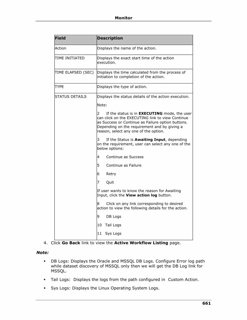
Monitor
661
Field Description
Action Displays the name of the action.
TIME INITIATED Displays the exact start time of the action execution.
TIME ELAPSED (SEC) Displays the time calculated from the process of initiation to completion of the action.
TYPE Displays the type of action.
STATUS DETAILS Displays the status details of the action execution.
Note:
2 If the status is in EXECUTING mode, the user can click on the EXECUTING link to view Continue as Success or Continue as Failure option buttons.
Depending on the requirement and by giving a reason, select any one of the option.
3 If the Status is Awaiting Input, depending on the requirement, user can select any one of the
below options:
4 Continue as Success
5 Continue as Failure
6 Retry
7 Quit
If user wants to know the reason for Awaiting Input, click the View action log button.
8 Click on any link corresponding to desired action to view the following details for the action.
9 DB Logs
10 Tail Logs
11 Sys Logs
4. Click Go Back link to view the Active Workflow Listing page.
Note:
▪ DB Logs: Displays the Oracle and MSSQL DB Logs. Configure Error log path
while dataset discovery of MSSQL only then we will get the DB Log link for
MSSQL.
▪ Tail Logs: Displays the logs from the path configured in Custom Action.
▪ Sys Logs: Displays the Linux Operating System Logs.
IBM Resiliency Orchestration Administrator’s Guide
© IBM Corporation 2017 662
In the Workflow Actions tab, the actions are grouped under the respective Action
Groups so that you can clearly know the action belongs to which Action Group.
Note:
Time Elapsed in the Workflow and total time elapsed for all Custom actions in the
workflow is not the same. It is dependent on multiple other factors.
Health Monitoring
The health of the group is continuously monitored and the current status is available
as a Group Health Graph in the Recovery group page. When there is a change in the
status of the health of the groups an event arises.
To navigate to the Group Health Graph, click Monitor OR Manage on the
Navigation bar. Then click Recovery Group. The Group Health meter in the
RG page displays the number of recovery groups under each state.
Viewing Group Relationship
Click IBM Resiliency Orchestration Server User Role Management to see the
privileges.
To view relationship details of a Group, perform following steps:
1. Click Monitor on the navigation bar. The RG Listing/ AG
Listing page appears.
2. Click desired Group from the GROUP NAME column. The
Recovery Group listing page for the respective RG or AG appears.
3. View the Relationship diagram.
Group Dependency
The Group Dependency tab under the Application Group displays visual
representation of all RGs dependent on the AG. Click each RG name against its box
to display its Recovery Group. You can also view the order in which Failover will be
done during disaster recovery by checking the arrow above Group Failover order.
Recovery Group Relationship
You can view the relationship between the configured production and the DR in a
pictorial representation by navigating to the Recovery Group Details. This page
displays the solution specific replication details, names and status of the datasets,
protection scheme and components on production and DR servers.

Monitor
663
You can expand or collapse the Replication, Component, and Dataset details by
clicking Expand All and Collapse All link at the top right corner of the page.
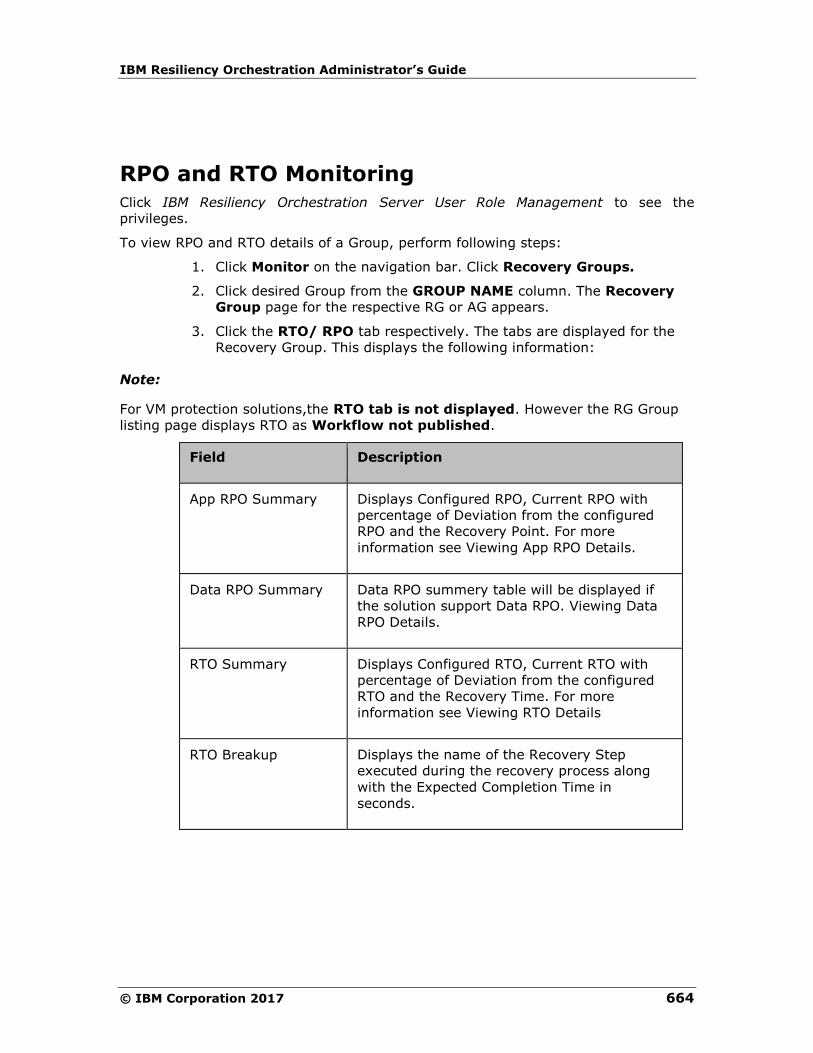
IBM Resiliency Orchestration Administrator’s Guide
© IBM Corporation 2017 664
RPO and RTO Monitoring
Click IBM Resiliency Orchestration Server User Role Management to see the
privileges.
To view RPO and RTO details of a Group, perform following steps:
1. Click Monitor on the navigation bar. Click Recovery Groups.
2. Click desired Group from the GROUP NAME column. The Recovery
Group page for the respective RG or AG appears.
3. Click the RTO/ RPO tab respectively. The tabs are displayed for the
Recovery Group. This displays the following information:
Note:
For VM protection solutions,the RTO tab is not displayed. However the RG Group
listing page displays RTO as Workflow not published.
Field Description
App RPO Summary Displays Configured RPO, Current RPO with
percentage of Deviation from the configured
RPO and the Recovery Point. For more
information see Viewing App RPO Details.
Data RPO Summary Data RPO summery table will be displayed if
the solution support Data RPO. Viewing Data
RPO Details.
RTO Summary
Displays Configured RTO, Current RTO with
percentage of Deviation from the configured
RTO and the Recovery Time. For more
information see Viewing RTO Details
RTO Breakup Displays the name of the Recovery Step
executed during the recovery process along
with the Expected Completion Time in
seconds.

Monitor
665
Continuity Monitoring Overview
Monitoring facilitates viewing the state information of the continuity operations
execution, the replication statistics, and the Events for the groups being monitored.
Once the groups are in Managed state, you can monitor the following:
▪ Continuity - Provides information about the continuity state of the group
along with the current status of the RPO and RTO.
▪ Replication - Provides information about the replication mechanism along with
the details of data or files replicated for the respective group.
▪ Events - Provides information about significant Events and warnings for the
respective groups.
Click on the respective link to view the current status of the list of groups being
monitored. If you want to view the detailed information about Continuity or
Replication or Events for a specific group, click on the group from the Group Name
column available in the respective links.
Note
From Recovery Group or Application Group Dashboard in Continuity, Replication or
Events, you can navigate to Monitor, Manage, Reports, Drills or Discover page of a
displayed group by clicking on respective icon at the
top right corner of the respective group’s dashboard window.
Monitoring Replication
You can view the detailed Replication List by clicking Monitor > Recovery Groups
and the Recovery Groups Listing page appears.
Select any Group name and click Group Replication tab.
In the Replication page you can monitor the replication process for each group by
viewing the detailed replication status of the group and the protection scheme
associated with the Group. Storage related information of the monitored RG and
information about data consistency i.e whether the DR site is in sync with the
Production without respect to data replication are also displayed. For example for a
Group configured under the SRDF Protection Scheme you can view the IDs of the
source and target symmetric units.
The Replication tab displays the Data log and the last updated time the files have
been replicated.
Field Description
Data Lag Displays the data lag information for the RG

IBM Resiliency Orchestration Administrator’s Guide
© IBM Corporation 2017 666
Field Description
Last Updated Displays the time when the RG was last updated
Click Refresh Details to refresh the replication page.
The replication details are displayed in the table:
Field Description
Protection Displays the replication type
Replication status Displays the status of the replication, Active Inactive and Unknown
Primary-Remote service
Displays the PR and DR information
Note
This table consists of basic information for all groups. Additional information will be
displayed, depending on the Replication Type.
Viewing Recovery Group Replication Details
To view the DR Solution specific replication details of the RG, perform the following
steps:
1 Click Monitor > Recovery Groups. The RG Listing Page appears.
2 Click Group Name in the RG Listing Page.
3 Click the Replication tab.
4 The Replication Details page is displayed that lists the DR Solution specific
replication details. The Replication tab is displayed only for that Recovery Group.
You can monitor the current status of the replication between the production and DR.
For example, in the case of SRDF protection mechanism, the details of the protection
mechanism, the specific device names, the status of the WAN link connection
between the two RDF devices the mode of replication i.e synchronous or
asynchronous and the number of invalid tracks are displayed.
Click the Refresh Details to refresh the information.

Events
667
Events
Event Life Cycle
Every event has a life cycle. When an event occurs, its status is "New", for which
some action (manual or automated) might be required. When the action is being
taken the event is associated with "Response in Progress" status. After completion of
the action, the event is associated with "Closed" status.
Automatic Closing of Events upon Aging
Aging is a process of moving unattended "New" events to "Closed" state. By default,
the aging period is set to 5 days. The aging is computed/performed at 00:00 AM
every day. All Events irrespective of its Severity but with "New" state older than the
aging period will be moved to "Closed" state except for User Input events.
Handling UserInputRequiredEvents
UserInputRequiredEvents cannot be moved to "Closed" or "Response in Progress"
states by the user. Once input for an userInputRequiredEvent is provided, it will be
moved to Closed state immediately. However, the corresponding
userInputObtainedEvent will be closed during aging process (or user can move it to
"Closed" state).
When IBM Resiliency Orchestration Server is started all userInputEvents
(userInputRequiredEvent/userInputObtainedEvent) will be moved to "Closed" state
irrespective of its status.
Events with policy execution
When the policy execution succeeds, the corresponding event will be automatically
moved to "Closed" state. Incase the policy fails, the event will be moved to
"Response in Progress" state automatically. The user is expected to respond to such
events and move to Closed state.

IBM Resiliency Orchestration Administrator’s Guide
© IBM Corporation 2017 668
Event Alarm
Event Alarm displays the number of critical events, serious events and input required
events across the applications. This will be displayed below navigation bar on all the
windows of the IBM Resiliency Orchestration.
The Critical Events are displayed in Red, and Input Required Events in Blue as shown
below:
If there are no corresponding events, then it will show zero. These counts will refresh
automatically in every 60 seconds. By default, these counts are shown for events
occurred in the past 5 days.
Click the corresponding icon on the Current Events to see the filtered list of events
based on severity. This navigates you to the View Events page.
User can also click on the Critical icon to view only critical events and UserInput
icon to view only UserInput events.
View Events
The Events DETAILS page displays Group events, user-input-required events and
System events. It displays the events occurred in the past 5 days by default.
Click IBM Resiliency Orchestration Server User Role Management to see the
privileges.
To view Events details, perform the following steps:
1. Click Current Events link in the Secondary Navigation Bar in the top right corner.
The Events page appears.
Following table explains the specific information displayed in the Events page.
Fields Functions and Descriptions
Advanced Filter This option allows advanced filter facility for events, based on event severity, user-input events and group names.
For more information, see Filtering Events.
Include Select the check box(es) to filter the events based on it's severity.
The available check boxes are Critical, Serious
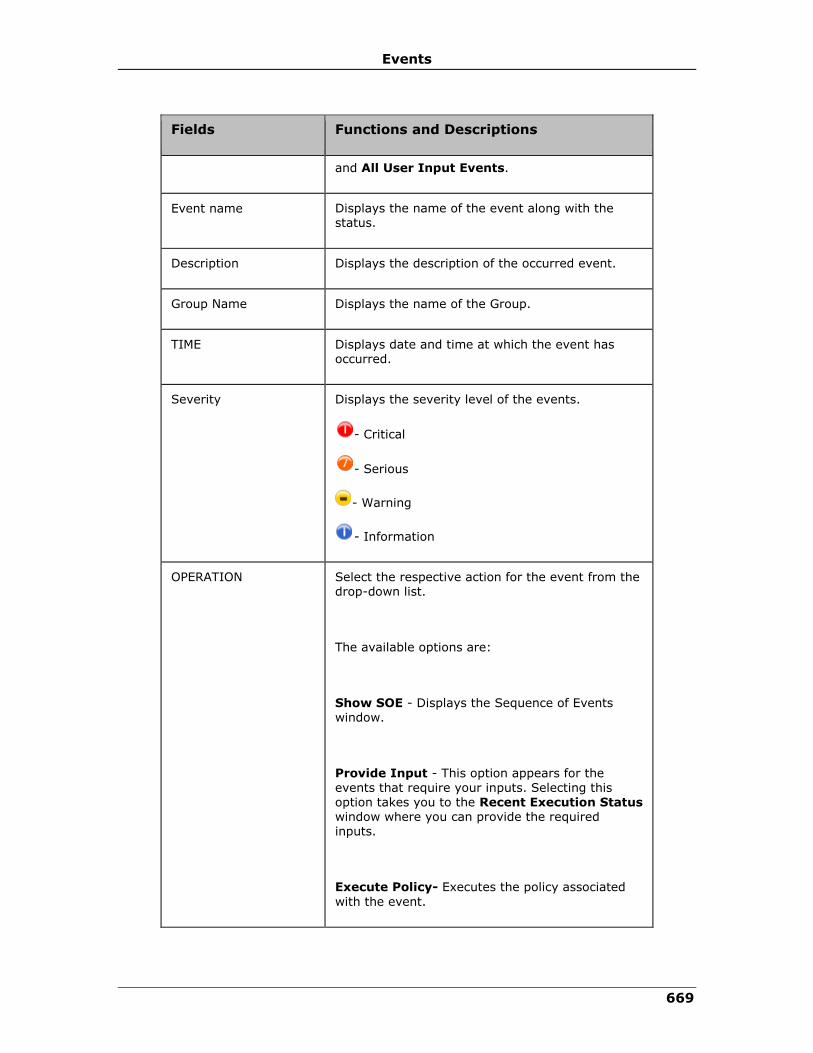
Events
669
Fields Functions and Descriptions
and All User Input Events.
Event name Displays the name of the event along with the status.
Description Displays the description of the occurred event.
Group Name Displays the name of the Group.
TIME Displays date and time at which the event has occurred.
Severity Displays the severity level of the events.
- Critical
- Serious
- Warning
- Information
OPERATION Select the respective action for the event from the drop-down list.
The available options are:
Show SOE - Displays the Sequence of Events window.
Provide Input - This option appears for the
events that require your inputs. Selecting this option takes you to the Recent Execution Status window where you can provide the required inputs.
Execute Policy- Executes the policy associated
with the event.
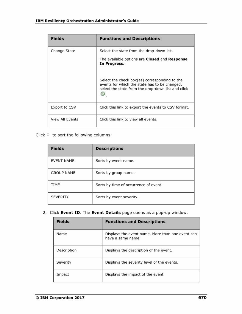
IBM Resiliency Orchestration Administrator’s Guide
© IBM Corporation 2017 670
Fields Functions and Descriptions
Change State Select the state from the drop-down list.
The available options are Closed and Response In Progress.
Select the check box(es) corresponding to the events for which the state has to be changed, select the state from the drop-down list and click
.
Export to CSV Click this link to export the events to CSV format.
View All Events Click this link to view all events.
Click to sort the following columns:
Fields Descriptions
EVENT NAME Sorts by event name.
GROUP NAME Sorts by group name.
TIME Sorts by time of occurrence of event.
SEVERITY Sorts by event severity.
2. Click Event ID. The Event Details page opens as a pop-up window.
Fields Functions and Descriptions
Name Displays the event name. More than one event can have a same name.
Description Displays the description of the event.
Severity Displays the severity level of the events.
Impact Displays the impact of the event.

Events
671
Occurred On Displays group on which the event has occurred.
Occurred Time Displays time at which the event has occurred.
Policy Status Displays the policy status if policy is applicable for the event.
3. Click Close.
Note:
In some case, the "Provide Input" operation will be shown even for events for which
the input is already provided by some other user or in some other window. In these
cases, the user will be redirected to the workflow page but will not see the workflow
waiting for input. Refreshing the events page will remove these events from the list.
Viewing Group Events
Click IBM Resiliency Orchestration Server User Role Management to see the
privileges.
To view Group Events details, perform the following steps:
1. Click DISCOVER > Groups on the navigation bar. The Groups page appears.
2. Click Recovery Group tab, the Group listing page appears.
3. Click the required group from the GROUP NAME column. The Group Details
Page appears.
4. Click the Group Configuration tab.
5. Click the Events tab.
Field Description
Event ID Displays the respective Event ID which identifies
each event.
Event Description Provides a brief description of the respective event.
Event Severity Displays the level of severity of the respective event.
Event Impact Provides information on affect/effects about the event.
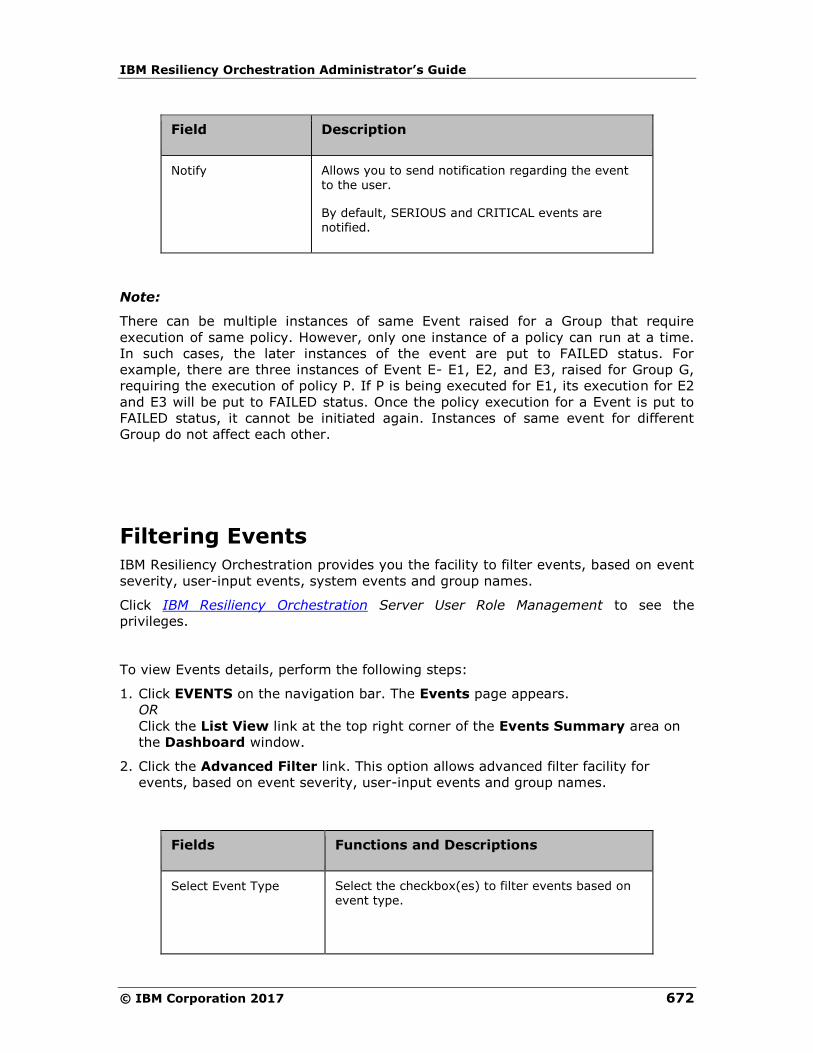
IBM Resiliency Orchestration Administrator’s Guide
© IBM Corporation 2017 672
Field Description
Notify Allows you to send notification regarding the event to the user.
By default, SERIOUS and CRITICAL events are notified.
Note:
There can be multiple instances of same Event raised for a Group that require
execution of same policy. However, only one instance of a policy can run at a time.
In such cases, the later instances of the event are put to FAILED status. For
example, there are three instances of Event E- E1, E2, and E3, raised for Group G,
requiring the execution of policy P. If P is being executed for E1, its execution for E2
and E3 will be put to FAILED status. Once the policy execution for a Event is put to
FAILED status, it cannot be initiated again. Instances of same event for different
Group do not affect each other.
Filtering Events
IBM Resiliency Orchestration provides you the facility to filter events, based on event
severity, user-input events, system events and group names.
Click IBM Resiliency Orchestration Server User Role Management to see the
privileges.
To view Events details, perform the following steps:
1. Click EVENTS on the navigation bar. The Events page appears.
OR
Click the List View link at the top right corner of the Events Summary area on
the Dashboard window.
2. Click the Advanced Filter link. This option allows advanced filter facility for
events, based on event severity, user-input events and group names.
Fields Functions and Descriptions
Select Event Type Select the checkbox(es) to filter events based on event type.
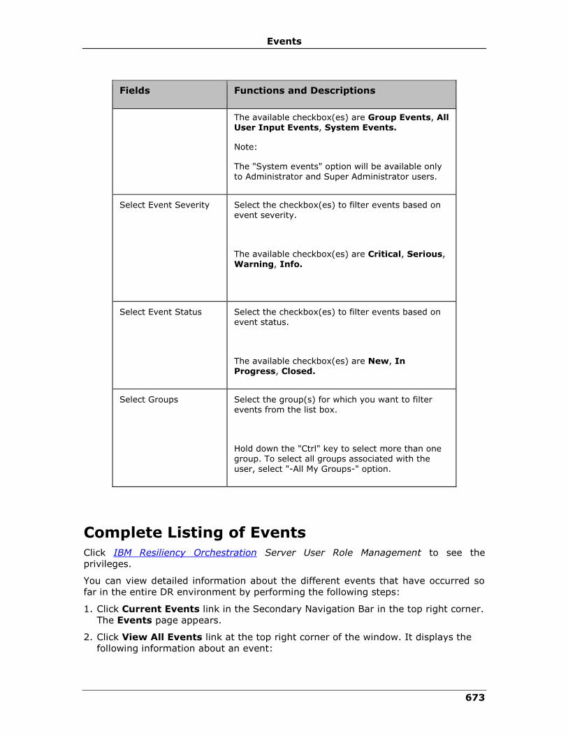
Events
673
Fields Functions and Descriptions
The available checkbox(es) are Group Events, All User Input Events, System Events.
Note:
The "System events" option will be available only to Administrator and Super Administrator users.
Select Event Severity Select the checkbox(es) to filter events based on event severity.
The available checkbox(es) are Critical, Serious, Warning, Info.
Select Event Status Select the checkbox(es) to filter events based on event status.
The available checkbox(es) are New, In Progress, Closed.
Select Groups Select the group(s) for which you want to filter events from the list box.
Hold down the "Ctrl" key to select more than one group. To select all groups associated with the user, select "-All My Groups-" option.
Complete Listing of Events
Click IBM Resiliency Orchestration Server User Role Management to see the
privileges.
You can view detailed information about the different events that have occurred so
far in the entire DR environment by performing the following steps:
1. Click Current Events link in the Secondary Navigation Bar in the top right corner.
The Events page appears.
2. Click View All Events link at the top right corner of the window. It displays the
following information about an event:
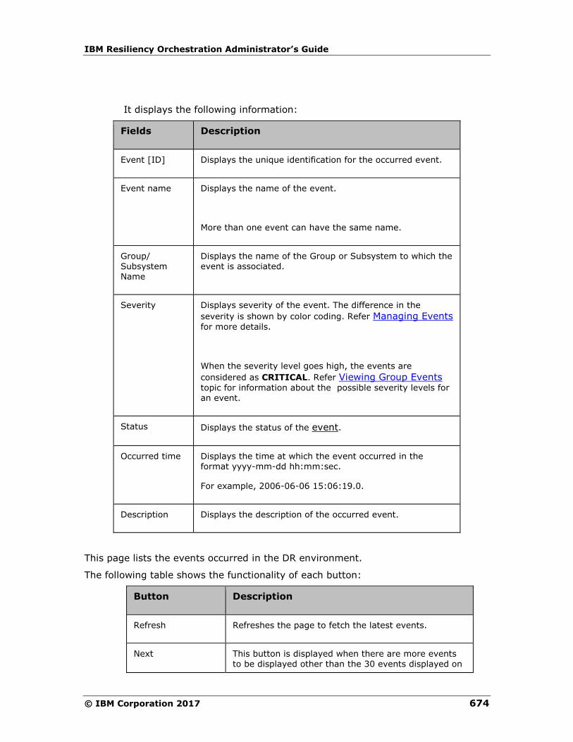
IBM Resiliency Orchestration Administrator’s Guide
© IBM Corporation 2017 674
It displays the following information:
Fields Description
Event [ID] Displays the unique identification for the occurred event.
Event name Displays the name of the event.
More than one event can have the same name.
Group/ Subsystem Name
Displays the name of the Group or Subsystem to which the event is associated.
Severity Displays severity of the event. The difference in the
severity is shown by color coding. Refer Managing Events
for more details.
When the severity level goes high, the events are
considered as CRITICAL. Refer Viewing Group Events
topic for information about the possible severity levels for
an event.
Status Displays the status of the event.
Occurred time Displays the time at which the event occurred in the format yyyy-mm-dd hh:mm:sec.
For example, 2006-06-06 15:06:19.0.
Description Displays the description of the occurred event.
This page lists the events occurred in the DR environment.
The following table shows the functionality of each button:
Button Description
Refresh Refreshes the page to fetch the latest events.
Next This button is displayed when there are more events to be displayed other than the 30 events displayed on
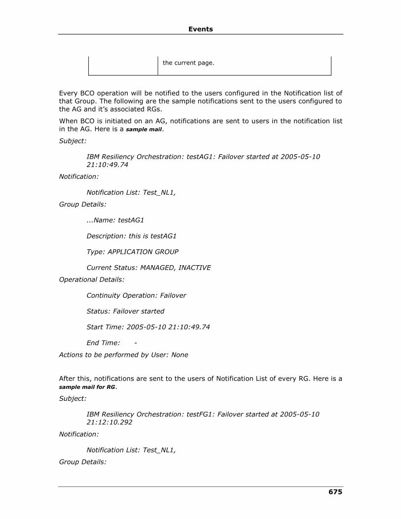
Events
675
the current page.
Every BCO operation will be notified to the users configured in the Notification list of
that Group. The following are the sample notifications sent to the users configured to
the AG and it’s associated RGs.
When BCO is initiated on an AG, notifications are sent to users in the notification list
in the AG. Here is a sample mail.
Subject:
IBM Resiliency Orchestration: testAG1: Failover started at 2005-05-10
21:10:49.74
Notification:
Notification List: Test_NL1,
Group Details:
...Name: testAG1
Description: this is testAG1
Type: APPLICATION GROUP
Current Status: MANAGED, INACTIVE
Operational Details:
Continuity Operation: Failover
Status: Failover started
Start Time: 2005-05-10 21:10:49.74
End Time: -
Actions to be performed by User: None
After this, notifications are sent to the users of Notification List of every RG. Here is a
sample mail for RG.
Subject:
IBM Resiliency Orchestration: testFG1: Failover started at 2005-05-10
21:12:10.292
Notification:
Notification List: Test_NL1,
Group Details:
IBM Resiliency Orchestration Administrator’s Guide
© IBM Corporation 2017 676
Name: testFG1
Description: this is testFG1
Type: FUNCTIONAL GROUP
Current Status: MANAGED, INACTIVE
Operational Details:
Continuity Operation: Failover
Status: Failover started
Start Time: 2005-05-10 21:12:10.292
End Time: -
Actions to be performed by User: None
If a user input is required, then a notification is sent to all the users of the
Notification lists of the RG. Click here to see a sample mail.
Subject:
IBM Resiliency Orchestration: testFG1: Failover waiting for user input since
2005-05-10 21:13:17.953
Notification:
Notification List: Test_NL1,
Group Details:
Name: testFG1
Description: this is testFG1
Type: FUNCTIONAL GROUP
Current Status: MANAGED, INACTIVE
Operational Details:
Continuity Operation: Failover
Status: Failover blocked, awaiting user input
Start Time: 2005-05-10 21:12:29.0
End Time: -
You have to perform the following actions:
Events
677
Login to IBM Resiliency Orchestration and take the necessary actions for the Group
“testFG1”.
When the BCO on RG failed/succeeded then notifications are sent.
Subject:
IBM Resiliency Orchestration: testFG1: Failover failed at 2005-05-10
21:49:38.0
Notification:
Notification List: Test_NL1,
Group Details:
Name: testFG1
Description: this is testFG1
Type: FUNCTIONAL GROUP
Current Status: MANAGED, INACTIVE
Operational Details:
Continuity Operation: Failover
Status: Failover failed
Start Time: 2005-05-10 21:12:29.0
End Time: 2005-05-10 21:49:38.0
Perform the following actions:
Log in to IBM Resiliency Orchestration and check the detailed Workflow status on the
Application/ Recovery Group > RG listing > Group Name > Continuity Workflow Details
link to determine the reasons for failure.
When a BCO on RG fails, it translates to a AG failure. Then a notification is sent to all
notification lists of the AG.
Subject:
IBM Resiliency Orchestration: testAG1: Failover failed at 2005-05-10
21:50:04.0
Notification:
Notification List: Test_NL1
Group Details:
Name: testAG1
Description: this is testAG1
IBM Resiliency Orchestration Administrator’s Guide
© IBM Corporation 2017 678
Type: APPLICATION GROUP
Current Status: MANAGED, INACTIVE
Operational Details:
Continuity Operation: Failover
Status: Failover failed
Start Time: 2005-05-10 21:12:08.0
End Time: 2005-05-10 21:50:04.0
You have to perform the following actions:
Log in to IBM Resiliency Orchestration and check the detailed action set status on the
Continuity pages to determine the reasons for failure.
Viewing Sequence of Events
The SOE bands are configured to show hours in the top band, and dates in the lower
band. These bands are configured to synchronize with each other such that panning
one band scrolls the other. The initial view of the Timeline format displays the
current date and time centered on the screen. Any events that have recently
occurred will be displayed. You can scroll by double clicking the mouse pointer on the
right or left side of the Timeline format.
Events are identified by name on the Timeline. Icons next to each event on the
Timeline will be the same icons used in the tabular list. Clicking on an event will pop-
up a bubble containing the time stamp associated with the event, the event number
and event description. You can close the pop-up by clicking anywhere outside the
bubble but within the Timeline format or by clicking the icon.
On clicking the Events tab, the sequence of events graph is displayed. The user can
also view the events by following the path below.
Click IBM Resiliency Orchestration Server User Role Management to see the
privileges.
To view sequence of events:
1. Click Current Events link in the Secondary Navigation Bar in the top right
corner. The Events page appears.
2. Select Show SOE from the Select Action drop-down list under OPERATION.
The Sequence of Events page appears.
Events
679
System Events
System events can be viewed only by super administrator or administrator. At least
one notification list or SNMP Trap Forwarder must be configured to receive
notifications regarding system events. There will not be any policy configuration for
system events.
Note:
There will not be any auto refresh to this page.
To view system events:
1. Click Admin > System Events on the navigation bar.
2. The System Events page appears with the following information.
Field Description
Event ID Displays the respective Event ID which identifies each event.
Event Description Provides a brief description of the respective event.
Event Severity Displays the level of severity of the respective event.
Event Impact Provides information on affect/effects about the event.
Notify Allows you to send notification regarding the event to the user.
By default, SERIOUS and CRITICAL events are notified.
3. Select the check box corresponding to the Event ID for which you want to
notify the user on occurrence of it.
Note:
To receive notification regarding the event, at least one notification list or SNMP Trap
Forwarder must be associated with the group. For more information on creating
notification list, refer to Adding Notification List.
4. Click the Update Selection button.
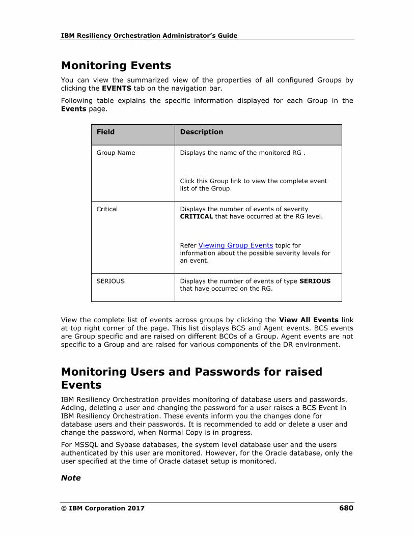
IBM Resiliency Orchestration Administrator’s Guide
© IBM Corporation 2017 680
Monitoring Events
You can view the summarized view of the properties of all configured Groups by
clicking the EVENTS tab on the navigation bar.
Following table explains the specific information displayed for each Group in the
Events page.
Field Description
Group Name Displays the name of the monitored RG .
Click this Group link to view the complete event
list of the Group.
Critical Displays the number of events of severity CRITICAL that have occurred at the RG level.
Refer Viewing Group Events topic for
information about the possible severity levels for an event.
SERIOUS Displays the number of events of type SERIOUS that have occurred on the RG.
View the complete list of events across groups by clicking the View All Events link
at top right corner of the page. This list displays BCS and Agent events. BCS events
are Group specific and are raised on different BCOs of a Group. Agent events are not
specific to a Group and are raised for various components of the DR environment.
Monitoring Users and Passwords for raised
Events
IBM Resiliency Orchestration provides monitoring of database users and passwords.
Adding, deleting a user and changing the password for a user raises a BCS Event in
IBM Resiliency Orchestration. These events inform you the changes done for
database users and their passwords. It is recommended to add or delete a user and
change the password, when Normal Copy is in progress.
For MSSQL and Sybase databases, the system level database user and the users
authenticated by this user are monitored. However, for the Oracle database, only the
user specified at the time of Oracle dataset setup is monitored.
Note

Events
681
Avoid using system level log-in credential while adding or deleting a user. This is to
avoid failing the operations running on the database, if you change the password
later.
IBM Resiliency Orchestration monitors the users and passwords related changes
every ten minutes. If more than one users are added in less than ten minutes, these
changes are summarized and reported in a single event. If one or more users are
added and deleted in less than ten minutes, two separate events are raised, one
each for adding and deleting users.

IBM Resiliency Orchestration Administrator’s Guide
© IBM Corporation 2017 682
group_dashboard_overview_htm
Recovery Automation
Managing Groups
Group Maintenance - Working with Different Modes of Group
This chapter describes how to change the modes of a Group.
However, Group's BCM state may change automatically as a result of failure of one
of the actions in a BCO.
Such situations are handled by IBM Resiliency Orchestration itself in the concrete DR
Solution. In a generic DR Solutions, IBM Resiliency Orchestration provides facility to
customize BCO workflows as per your needs. As part of this customization, you can
trigger another BCO, if the current BCO fails. This is achieved by adding a Trigger
BCO action manually in the workflow. However, it may be possible that the intended
action from Trigger BCO is already completed or in progress, when the current BCO
fails. This results in the failure of Trigger BCO action. In such cases, click Continue
in the Workflow Manager page to skip the failed action and to move to the next.
Continuity Management Overview
You can view the list of groups being managed by IBM Resiliency Orchestration by
clicking
either the Monitor or the Manage tab on the IBM Resiliency Orchestration GUI.
As soon as the groups are configured, you can edit, delete and manage the following
by clicking the Manage tab on the IBM Resiliency Orchestration GUI:

Recovery Automation
683
• RG Listing - Provides the list of groups being managed with the group
continuity state and the Workflow details.
• Executing Workflows - Provides the list of current actions of the respective
continuity operations being executed.
Click the respective links to view the current continuity operation and action set
being executed for a specific group.
Click on to sort the following columns:
Field Name Description
GROUP NAME Sorts by group states
CURRENT STATE Sorts by group continuity states
Note:
In Manage:
▪ You can change continuity states.
▪ You can initiate BCOs.
▪ You can Start and Stop replication.
To navigate to Monitor, Reports, Drills or Discover page of a displayed group:
1. Click Manage
2. Select the required tab from the drop down.
Note:
If the Group is in Switchover mode, it cannot be managed with only the Recovery
license enabled. To manage the Group, enable the Test license and change the state
to Normal mode.
Changing Group to Managed Mode
Any BCO on the Group can be performed only when the Group is in the Managed
state.
Click IBM Resiliency Orchestration Server User Role Management to see the
privileges.
To change the Group to MANAGED mode, perform the following steps:
1. Click DISCOVER > Groups on the navigation bar. The Groups page appears.

IBM Resiliency Orchestration Administrator’s Guide
© IBM Corporation 2017 684
2. Click Recovery Group or Application Group tab, the respective Group listing
page appears.
3. Click corresponding to the desired group. The Continuity Operation window
appears.
4. Click the Manage Group button.
Note:
You cannot modify the Group details, when the Group is in Managed mode.
5. A message box with successful Group mode change operation is displayed.
Click OK on the message box displayed.
If the Group is in MANAGED mode currently and not executing any continuity
operation, it may be put into MAINTENANCE mode.
Changing Group to Maintenance Mode
Note
If a policy is being executed for a Group, you cannot change that Group to
Maintenance mode. Trying to move it anyway will display an error message. You may
need to stop the policy execution or let it complete before changing the Group to
Maintenance mode.
Click IBM Resiliency Orchestration Server User Role Management to see the
privileges.
To change the Group into Maintenance mode, perform the following steps:
1. Click DISCOVER > Groups on the navigation bar. The Groups page appears.
2. Click Recovery Group or Application Group tab, the respective Group listing
page appears.
3. Click corresponding to the desired group. The Continuity Operation window
appears.
The maintenance activities can be used by the owner of the Group to bypass certain
activities or to recover from certain failures. All maintenance related activities should
be done only after moving the corresponding Group to Maintenance mode. Further,
all related agents should be stopped before performing maintenance activities.
Caution
Usage of this activity, if not performed correctly, may significantly impact the
Continuity Management of the Group. It is not recommended to be used by the end
user.
4. Click the Move to Maintenance button.
Recovery Automation
685
5. A message box with successful Group mode change operation is displayed.
Click OK in the message box displayed.
Note
To manage AG's, all the RG's should have similar modules assigned to them. And
each RG inside the AG should have atleast one module assigned.
icon corresponding to a group is enabled and you can change the group to
maintenance mode when no workflows are running or when BP workflows or event
policy workflows are running.
icon corresponding to a group is disabled and you cannot change the group to
maintenance mode during any BCO or SO/SB drills execution.
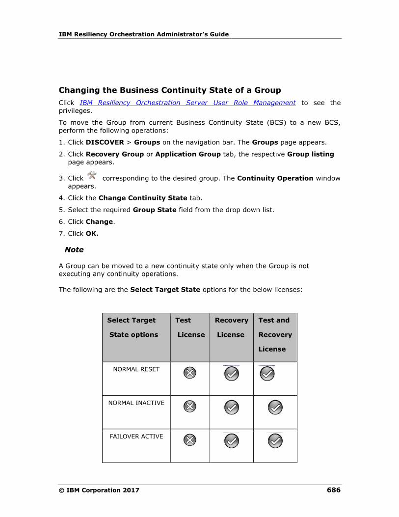
IBM Resiliency Orchestration Administrator’s Guide
© IBM Corporation 2017 686
Changing the Business Continuity State of a Group
Click IBM Resiliency Orchestration Server User Role Management to see the
privileges.
To move the Group from current Business Continuity State (BCS) to a new BCS,
perform the following operations:
1. Click DISCOVER > Groups on the navigation bar. The Groups page appears.
2. Click Recovery Group or Application Group tab, the respective Group listing
page appears.
3. Click corresponding to the desired group. The Continuity Operation window
appears.
4. Click the Change Continuity State tab.
5. Select the required Group State field from the drop down list.
6. Click Change.
7. Click OK.
Note
A Group can be moved to a new continuity state only when the Group is not
executing any continuity operations.
The following are the Select Target State options for the below licenses:
Select Target
State options
Test
License
Recovery
License
Test and
Recovery
License
NORMAL RESET
NORMAL INACTIVE
FAILOVER ACTIVE

Recovery Automation
687
Select Target
State options
Test
License
Recovery
License
Test and
Recovery
License
FALLBACK ACTIVE
SWITCHOVER INACTIVE
Note
▪ icon corresponding to a group is enabled and you can change the Business
Continuity State of a Group when no workflows are running or when BP
workflows or event policy workflows are running.
▪ icon corresponding to a group is disabled and you cannot change the
Business Continuity State of a Group during any BCO or SO/SB drills
execution.
Business Continuity Operations
Based on the current BCM and BCS (Business Continuity State) of the Group,
continuity operations such as ‘Initiate NormalCopy’, ‘Initiate Failover’, 'Initiate
Fallback’ etc. are possible. These operations are listed as selectable buttons. The
complete list of operations is as given below:
Operations Description
Initiate NormalFullCopy
This operation initiates NormalFullCopy operation.
Initiate NormalCopy This operation initiates NormalCopy on the specified FG. This typically involves periodic extraction of data from production and application of changed data on
DR. In some DR Solutions, NormalCopy is a monitoring only operation, as the replication technology in use handles transferring the data between the production and DR databases.

IBM Resiliency Orchestration Administrator’s Guide
© IBM Corporation 2017 688
Operations Description
Stop NormalCopy This operation stops the NormalCopy on the Group under consideration. Clicking this button displays a
page to reconfirm the stopping of the operation.
Initiate Reverse NormalCopy
This operation is the reverse of the NormalCopy as this is initiated after the Switchover operation and
the data is replicated from production (configured DR) to the DR site (configured production).
Initiate Failover
This operation initiates Failover operation on the
Group during the failure of the production site.
Clicking this button displays a page to reconfirm the initiation of the operation.
Initiate Fallback This operation initiates a Fallback operation when production comes live again.
Change Continuity State
This operation lets you move a Group from the current BCS to a new BCS.
This operation is possible only when the Group is not executing any continuity operations currently.
Resume Operation This operation lets you to get back IBM Resiliency Orchestration server online after the server crash.
Note
In generic solutions, IBM Resiliency Orchestration provides facility to customize BCO
workflows as per your needs. As part of this customization, you can trigger another
BCO, if an action in the current BCO fails. This is achieved by adding a Trigger BCO
action manually in the workflow. However, it may be possible that the intended
action from Trigger BCO is already completed or in progress, when an action in the
BCO fails. This results in the failure of Trigger BCO action. In such cases, click
Continue in the Workflow Manager page to skip the failed action and to move to the
next.
The following table lists the next possible operation based on the current state of
operation.
Note
Reverse Copy button appear only when the DR Solution type supports these BCOs.
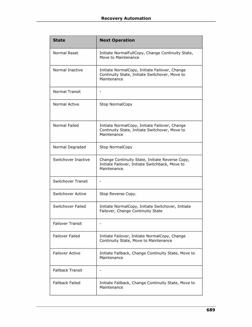
Recovery Automation
689
State Next Operation
Normal Reset Initiate NormalFullCopy, Change Continuity State, Move to Maintenance
Normal Inactive Initiate NormalCopy, Initiate Failover, Change Continuity State, Initiate Switchover, Move to Maintenance
Normal Transit -
Normal Active
Stop NormalCopy
Normal Failed Initiate NormalCopy, Initiate Failover, Change Continuity State, Initiate Switchover, Move to Maintenance
Normal Degraded Stop NormalCopy
Switchover Inactive Change Continuity State, Initiate Reverse Copy, Initiate Failover, Initiate Switchback, Move to Maintenance.
Switchover Transit -
Switchover Active Stop Reverse Copy.
Switchover Failed Initiate NormalCopy, Initiate Switchover, Initiate Failover, Change Continuity State
Failover Transit -
Failover Failed Initiate Failover, Initiate NormalCopy, Change Continuity State, Move to Maintenance
Failover Active Initiate Fallback, Change Continuity State, Move to Maintenance
Fallback Transit -
Fallback Failed Initiate Fallback, Change Continuity State, Move to Maintenance

IBM Resiliency Orchestration Administrator’s Guide
© IBM Corporation 2017 690
State Next Operation
Fallback Active Initiate FallbackResync, Change Continuity State, Move to Maintenance
Normal Shutdown Resume Continuity operation, Change Continuity State, Move to Maintenance
Normal Stopping -
Normal Test Initiate NormalCopy, Initiate Failover, Change
Continuity State, Initiate Switchover, Move to Maintenance
(Do not perform any BCO when the test exercise are being performed on the Group)
The following table technically explains the Business Continuity Operations and the
state of production and DR server. It is applicable only for DR Solutions based on
Sybase and MSSQL databases.
BCO
Functionality
Production
Server’s
mode of
operation
DR
Server’s
mode of
operation
Before NormalFullCopy
Nil
Read, Write
No existence of database
After NormalFullCopy
Takes full dump of data from production to DR site and both servers are in sync with each other.
Read, Write Standby
NormalCopy Copies incremental log files from the production to DR.
Read, Write Standby
Reverse NormalCopy
(Not supported for DR Solutions
based on
Copies log files from current production site to current DR site.
Standby Read, Write

Recovery Automation
691
BCO
Functionality
Production
Server’s
mode of
operation
DR
Server’s
mode of
operation
MSSQL and
Sybase databases)
Auto Failover Production server is brought down and the DR server is made available
for access.
No Data is available
Read, Write
Manual Failover Standby Read/Write
Before Fallback Start
The server at the production site should not
have any data.
NA Read/Write
After Fallback The existing copy of data on the DR server (current
production server) is copied to the production. The data on the remote is deleted after a copy is
made to the production.
Read/Write Standby
FallbackResync This operation copies the incremental log on the current production server (DR) to the production server.
Read/Write
Standby
At the end of FallbackResync
The production server is brought back to production and the DR server is made
stand-by
Read/Write Standby
IBM Resiliency Orchestration Administrator’s Guide
© IBM Corporation 2017 692
Configuration of BCOs
Every Group is associated to business continuity operations (BCO) through the
supported DR Solution types. The continuity operations for a Group are as follows:
▪ NormalFullCopy
▪ NormalCopy
▪ Failover
▪ Fallback
▪ FallbackResync
BCOs are configured when the actions associated to each operation are configured.
To configure a BCO perform the following steps:
1 Click DISCOVER > Groups on the navigation bar. The Groups page appears.
2 Click Recovery Group or Application Group tab, the respective Group Listing
page appears.
3 Click the required group from the GROUP NAME column for which you want to
configure the BCOs. The Group Details Page appears.
4 Click the Group Configuration tab.
5 Click the Continuity tab.
6 Click respective BCO to configure its actions. This opens the Workflow Details
page with a list of actions.
Note
All actions should be configured before the execution of respective BCO.

Recovery Automation
693
NormalFullCopy
Click IBM Resiliency Orchestration Server User Role Management to see the
privileges.
To start the NormalFullCopy operation perform the steps provided in Executing
Business Continuity Operations topic in this Help.
In this operation, the full dump of the configured database on the production server
is copied to the DR server either manually or through network connection.
Refer to the ‘Executing BCOs’ topic in the respective solution guide under DR
Solutions Supported by IBM Resiliency Orchestration book in this Help for more
information on the execution of the NormalFullCopy operation.
At the end of this operation, the DR server goes to ‘standby’ mode and the
production server remains in read-write mode. At the end of this operation the DR
Solutions and the DR database are in-sync with each other.
When NormalFullCopy is initiated at the AG level, the operation gets triggered on the
associated RG to perform NormalFullCopy operation at the AG.
When this operation has been initiated, the actions associated with this operation will
be executed.
If Inform Upon is set to ‘ALL’ during the action configuration of this Business
Continuity Operation, then you can see a window pop-up displaying the status of the
operation at the completion of this operation. Suppose a particular action is not
executed correctly, then you can see action failure wizard. Click Retry button to re-
execute the action execution. If this message persists, please contact IBM Resiliency
Orchestration support.
If all the actions are executed, the Execution Status of the NormalFullCopy operation
can be viewed by clicking the Monitor OR Manage on the Navigation bar and
following the path-
Recovery Groups > Group Name > Continuity Workflows > Execution Status.
Note:
You can click the Pause/ Resume button at any time to pause or resume the
operation respectively for the Application Recovery on AWS solution (VMware to
AWS).
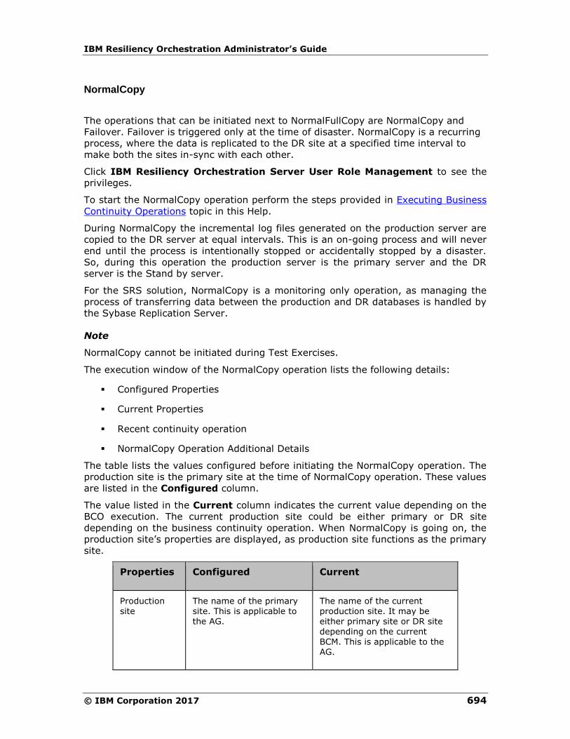
IBM Resiliency Orchestration Administrator’s Guide
© IBM Corporation 2017 694
NormalCopy
The operations that can be initiated next to NormalFullCopy are NormalCopy and
Failover. Failover is triggered only at the time of disaster. NormalCopy is a recurring
process, where the data is replicated to the DR site at a specified time interval to
make both the sites in-sync with each other.
Click IBM Resiliency Orchestration Server User Role Management to see the
privileges.
To start the NormalCopy operation perform the steps provided in Executing Business
Continuity Operations topic in this Help.
During NormalCopy the incremental log files generated on the production server are
copied to the DR server at equal intervals. This is an on-going process and will never
end until the process is intentionally stopped or accidentally stopped by a disaster.
So, during this operation the production server is the primary server and the DR
server is the Stand by server.
For the SRS solution, NormalCopy is a monitoring only operation, as managing the
process of transferring data between the production and DR databases is handled by
the Sybase Replication Server.
Note
NormalCopy cannot be initiated during Test Exercises.
The execution window of the NormalCopy operation lists the following details:
▪ Configured Properties
▪ Current Properties
▪ Recent continuity operation
▪ NormalCopy Operation Additional Details
The table lists the values configured before initiating the NormalCopy operation. The
production site is the primary site at the time of NormalCopy operation. These values
are listed in the Configured column.
The value listed in the Current column indicates the current value depending on the
BCO execution. The current production site could be either primary or DR site
depending on the business continuity operation. When NormalCopy is going on, the
production site’s properties are displayed, as production site functions as the primary
site.
Properties Configured Current
Production site
The name of the primary site. This is applicable to the AG.
The name of the current production site. It may be either primary site or DR site depending on the current BCM. This is applicable to the AG.

Recovery Automation
695
Properties Configured Current
Production server
The name of the primary server.
The name of the current production server.
DR site This gives the DR site name. This is applicable to the AG.
This gives the DR site name if applicable otherwise it’s shown as ‘Not Applicable’. This is applicable to the AG.
DR server The name of the DR server.
This gives the DR site name if applicable otherwise it’s shown
as ‘Not Applicable’.
BCMs This lists the possible BCMs of the Group. This is applicable to the AG.
This shows the ongoing BCM. This is applicable to the AG.
BCM State Not Applicable. This gives the current BCM state. For state details refer BCM configuration section under Group properties. This
is applicable to the AG.
Current
Group State
Current state of the
group. Current state of the group.
Current Continuity Status
Current continuity status of the group.
Current continuity status of the group.
Recent Continuity Operation: (displayed only at the FG level)
Continuity Operation The name of the recent BCO executed.
Start time Time stamp of recent BCO start.
End time Time stamp of BCO completion.
To view the actions configured for the current continuity operation, click on Workflow
Details link corresponding to the Continuity Operation.
Recent Continuity Operation: (only at AG level)
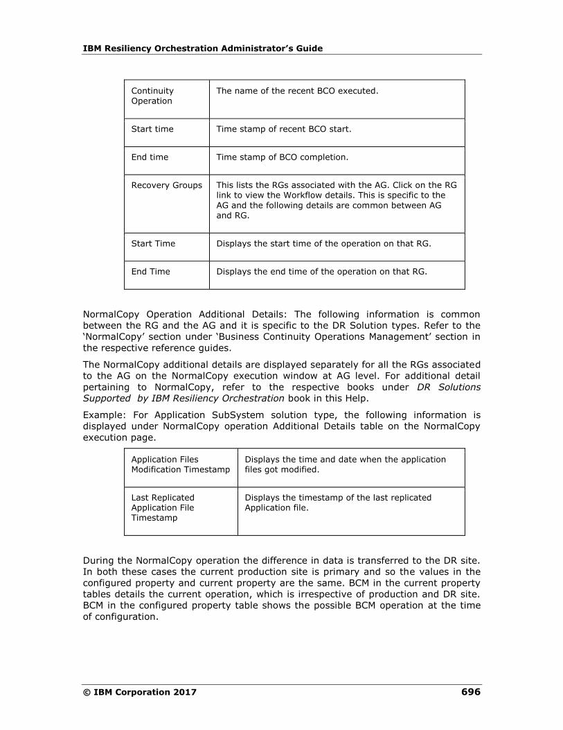
IBM Resiliency Orchestration Administrator’s Guide
© IBM Corporation 2017 696
Continuity Operation
The name of the recent BCO executed.
Start time Time stamp of recent BCO start.
End time Time stamp of BCO completion.
Recovery Groups This lists the RGs associated with the AG. Click on the RG link to view the Workflow details. This is specific to the
AG and the following details are common between AG and RG.
Start Time Displays the start time of the operation on that RG.
End Time Displays the end time of the operation on that RG.
NormalCopy Operation Additional Details: The following information is common
between the RG and the AG and it is specific to the DR Solution types. Refer to the
‘NormalCopy’ section under ‘Business Continuity Operations Management’ section in
the respective reference guides.
The NormalCopy additional details are displayed separately for all the RGs associated
to the AG on the NormalCopy execution window at AG level. For additional detail
pertaining to NormalCopy, refer to the respective books under DR Solutions
Supported by IBM Resiliency Orchestration book in this Help.
Example: For Application SubSystem solution type, the following information is
displayed under NormalCopy operation Additional Details table on the NormalCopy
execution page.
Application Files Modification Timestamp
Displays the time and date when the application files got modified.
Last Replicated Application File Timestamp
Displays the timestamp of the last replicated Application file.
During the NormalCopy operation the difference in data is transferred to the DR site.
In both these cases the current production site is primary and so the values in the
configured property and current property are the same. BCM in the current property
tables details the current operation, which is irrespective of production and DR site.
BCM in the configured property table shows the possible BCM operation at the time
of configuration.
Recovery Automation
697
For example: Assume that a disaster strikes at primary site, in this situation the
remote site has to be brought up to function as a production site. During this
operation the values of ‘Configured Property’ and ‘Current Property’ tables are
different as the current production site is DR site, BCM is Failover and DR site values
turns invalid as DR site does not exist during Failover operation.
Again during Fallback mode where the production starts functioning as primary, the
values in both the tables are same.
When the NormalCopy operation is stopped in response to an event that occurs
during data replication failure between production and the DR sites, then you can
automatically resume NormalCopy through a configured policy.
To know about the event and policy refer to Managing Events section of ‘Executing
BCOs’ chapter under DR Solution Supported by IBM Resiliency Orchestration book in
this Help.
You can set the frequency of dump and apply interval for NomalCopy at the time of
NormalCopy operation configuration for database log and Application SubSystem
solutions. Refer to the respective book under DR Solutions Supported by IBM
Resiliency Orchestration book in this Help for information on configuring the
NormalCopy frequency.
RPO and the Dump/Apply Intervals
The Apply Interval is usually set to more than or equal to the Dump Interval. The
RPO (Recovery Point Objective) should always be more than the greater of Dump
and Apply Log Interval. For example, if the Dump Interval is 5 minutes and the Apply
Interval is 10 minutes then, RPO should be 12 minutes or more.
IBM Resiliency Orchestration Administrator’s Guide
© IBM Corporation 2017 698
Reverse Normal Copy
This operation is performed after performing the Switchover operation. The Reverse
Copy operation is similar to the NormalCopy operation, but the replication happens
from the current production server to the current DR server.
The Reverse Copy operation execution page is same as the NormalCopy operation
execution page. To get information on the Reverse Copy operation page elements,
refer to ‘NormalCopy’ in this section.
Click IBM Resiliency Orchestration Server User Role Management to see the
privileges.
To start Reverse Copy operation perform the steps provided in Executing Business
Continuity Operations topic in this Help.
Fallback
During this operation a full dump of data from the current production server (DR
server) is copied to the configured production server. Then the configured production
server is brought back to production at the end of the Fallback operation.
At the end of the Fallback operation, the state of the DR database is dependent on
the supported DR Solution type. In all DR Solutions, the production database is
brought into production at the end of the Fallback operation.
In Application SubSystemand MSSQL solutions, the DR database is brought into the
mounted state at the end of Fallback operation but in Sybase solution, the DR
database is brought into standby mode in the beginning of the FallbackResync
operation.
Note
All the RGs linked to an AG will be failed over or fallen back together always. Any
failure in a RG is treated as a failure in all the RGs and the same continuity action is
performed on all.
Refer to Executing Business Continuity Operations for information on initiating
Fallback operation.
Failover
The Failover operation is initiated when the production server goes down. Failover
can be initiated either manually or automatically. Failover is manually initiated by
stopping the NormalCopy operation. It is automatically initiated when events are
configured to start this operation on occurrence of disaster. Based on the severity
level of the occurred Events, the corresponding configured policy set will initiate
Failover operation.
Recovery Automation
699
For example, if the production database is down, an event will be raised. This event
will stop the ongoing NormalCopy and will initiate the Failover operation.
Click IBM Resiliency Orchestration Server User Role Management to see the
privileges.
The execution status of the Failover operation cannot be seen as the operation
automatically triggered due to server down condition. During the server down
condition agents will not be able to connect to the server, and hence the execution
status of the Failover operation cannot be shown. Refer to Executing Business
Continuity Operations to know how to initiate Failover operation.
Failover operation can be performed only during certain situations after the sites are
switched over. IBM Resiliency Orchestration server is always placed in the configured
site i.e. DR site. After Switchover is performed, the configured DR becomes the
production server. So, the IBM Resiliency Orchestration server is said to be placed at
the production site after Switchover. In this case, if WAN link failure occurs between
the two sites, the control cannot be switched over to the DR site as it is done in
normal setup (where IBM Resiliency Orchestration server is placed in the remote
site) because IBM Resiliency Orchestration ™ is situated in the production site.
This setup (Switchover) supports Failover for the following conditions:
▪ Database down
▪ Database server down
This setup (Switchover) cannot support Failover for the following conditions:
▪ Site Collapse
▪ WAN link failure
IBM Resiliency Orchestration supports automatic failure when the events are
configured to initiate the Failover automatically on a failure or disaster. Otherwise,
the Failover operation is initiated manually.
For execution part of this operation based on the DR Solution type, refer to the
respective DR Solution reference guide.
When Failover is initiated at AG level, then this operation is executed on all RGs
associated to the AG. All the RGs will be failed over together always. Any failure in a
RG is treated as a failure in all the RGs and the same continuity action is performed
on all.
During Failover the DR server is brought into production. When the Failover
operation is executed on the Group, the ‘Additional Details’ section in the
NormalCopy page that displays the log file details cannot be seen as the Failover
operation is automatically triggered due to server down condition. During the server
down condition, agents will not be able to connect to the server, and hence, the
execution status of the Failover operation will not be shown.
Once Failover operation is complete, follow the path Manage > Recovery
Groups> Group Name > RG Details page initiate the next operation or refresh
the page to initiate next operation.
IBM Resiliency Orchestration Administrator’s Guide
© IBM Corporation 2017 700
The Failover time of the AG is calculated as sum of recovery time of all RGs
associated to the AG.
FallbackResync
This operation is initiated to bring the DR database and the production database in
sync.
Click IBM Resiliency Orchestration Server User Role Management to see the
privileges.
To start the FallbackResync operation perform the steps provided in Executing
Business Continuity Operations topic in this Help. This operation has to be started
from the AG level Groups page.
An Example to have a Clear Understanding of all Five BCOs
Assume that, the production site is at Bangalore and the DR site is at Mumbai.
During NormalFullCopy the full dump is manually transferred from Bangalore server
to the Mumbai server. This operation synchronizes the data on the two servers.
During NormalCopy operation only incremental data is transferred to the Mumbai
server.
Assume that a disaster strikes the production site (Bangalore) 10.A.M 10-10-2005.
The Failover operation transfers the business to the DR server and it starts
functioning as the current production server.
Assume that the collapsed site comes back online at 2 P.M the same day. In the
Fallback operation the full dump from the Mumbai (current production) server is
copied to the Bangalore server (current DR). This operation may take some amount
of time (say 4 hours), during which some more transactions may happen in the
current production site. This additional data is also copied at the end of the Fallback
operation and the Bangalore server is brought into production.
During FallbackResync operation, the two servers are brought into sync and are
made ready for the NormalCopy operation.
Executing Business Continuity Operations
You can enable continuity operations on a group and manage its state details by
clicking Manage tab on the navigation bar. During execution of the BCO, the actions
configured for that BCO is executed in the order of configuration.
You can stop IBM Resiliency Orchestration services at any time during the execution
of BCO.
Click IBM Resiliency Orchestration Server User Role Management to see the
privileges.
Recovery Automation
701
To execute NormalFullCopy, NormalCopy, or Reverse NormalCopy :
1. Click Manage> Recovery Groups > RG listing page is displayed. This page
lists all Groups assigned to the current user.
2. Click a group from the GROUP NAME column. Click View All Workflows.
3. The BCO workflows are displayed.
Note
Only Super Administrator can start/stop BCOs for Groups of other users. The users
with Administrator privileges can start BCOs for Groups assigned to them but cannot
stop BCOs initiated by other users for the same Groups.
4. Click the respective BCO to initiate the operation.
The following are the BCOs displayed:
▪ NormalFullCopy
▪ NormalCopy
▪ ReverseNormalCopy
Refer to Business Continuity Operations for more information.
5. Click Execute a confirmation pop-up is displayed with Execute and Cancel.
6. Click Execute to confirm the execution. Click Cancel to cancel the execution.
To execute Failover, Fallback, or FallbackResync :
1. Click Manage> Recovery Groups > RG listing page is displayed. This page
lists all Groups assigned to the current user.
2. Click a group from the GROUP NAME column. Click View All Workflows.
3. Click the Recovery Workflows tab to proceed with the continuity operations
execution.
Note
Only Super Administrator can start/stop BCOs for Groups of other users. The
users with Administrator privileges can start BCOs for Groups assigned to
them but cannot stop BCOs initiated by other users for the same Groups.
4. Click the respective BCO to initiate the operation.
The following are the BCOs displayed:
▪ Failover
▪ Fallback
▪ FallbackResync
Refer to Business Continuity Operations for more information.
5. Click Execute a confirmation pop-up is displayed with Execute and Cancel.
IBM Resiliency Orchestration Administrator’s Guide
© IBM Corporation 2017 702
6. Click Execute to confirm the execution. Click Cancel to cancel the execution.
On the Manage page, click the respective RG link under Recovery Groups to view
the list of actions executed on the RG along with the notification information. You can
manage the action being executed and choose to terminate a particular action from
the Recovery page.
Failover on any one of the RGs that are linked to an AG is defined as ‘Any BCO on
one is BCO on all’ i.e. if Failover is triggered on any one of the RG will trigger
Failover on the AG to which the RG is associated.
Note:
All RGs linked to an AG will be failed over or fallen back together always. Any failure
in a RG is treated as a failure in all the RGs and the same continuity operation is
performed on all RGs belonging to that AG.
Caution
Usage of the Failover operation may significantly impact the continuity management
of the Group, if not performed correctly.
Start and Stop Replication
The Replication Management allows protection parameter configuration, execution
and displays the health of replication activity. The replication mechanism is
applicable only in Normal mode. The Normal mode operation periodically obtains the
protection details and stores them. The Replication Management allows parallel
protection management operation on multiple Groups at the same time. You can
implement the configuration of protection parameters, based on the privilege
specification.
As part of the replication management, IBM Resiliency Orchestration provides the
following key capabilities for each database under protection:
▪ Monitor the health of WAN links (up or down conditions). This is applicable
only for an Application Group.
▪ Health of the log replication activity
▪ ndividual database level control
The above management capability is provided at each database level for higher
flexibility and decentralized management control.
The Replication Management is enabled only after the Group creation. The replication
status of the Application Group can be Active, Inactive, or Degraded based on the
status of the Recovery Group attached to it. The data replication occurs at the
Recovery Group level only. The replication failures are reported at Recovery Group
level, but elevated to Application Group level.

Recovery Automation
703
Click IBM Resiliency Orchestration Server User Role Management to see the
privileges.
Perform the following steps to initiate replication:
1. Click Manage> Recovery Groups on the navigation bar. The Recovery
Groups List page appears.
2. Click the desired Group from the Group Name column and click Replication
tab.
3. This page displays the replication details and you can monitor the health of the
data replication that is going on. You can perform the following operations on
the Group:
▪ Click Stop Replication to stop the replication after initiating the NormalCopy
operation.
▪ Click Start Replication to start replication to resume the operation after a
halt.
▪ Click Refresh Details to get latest replication details.
Note:
You can also Refresh Details by performing the following steps.
1. Click Monitor > Recovery Groups on the navigation bar. The Recovery
Groups List page appears.
2. Click the desired Group from the Group Name column and click Replication
tab.
3. Click Refresh Details to get latest replication details.
The information displayed in this page varies with the DR Solution type supported.
The replication properties depend on the BCO. The following topics explain about the
replication status during various BCO at Recovery Group and Application Group level.

IBM Resiliency Orchestration Administrator’s Guide
© IBM Corporation 2017 704
NormalFullCopy
The following details are displayed on the Recovery Group details > Replication tab.
Field Description
Replication Status Active
Last Successful
Replication Time Not Applicable
Last Failed Replication Time
Displays the time of the replication that had failed.
Last Replicated Data size
Displays the size of the data replicated. The data size is zero in case of replication failure or shows the replicated file size in case of successful replication.
In case of successful replication the value of Last replicated Data size increases as and when the additional data is copied from the Production to DR server.
NormalCopy and Reverse NormalCopy
The following details are displayed on the Recovery Group details > Replication tab.
Field Description
Fileset Name
Displays the name of the Fileset being replicated.
Protection Mechanism Displays the protection mechanism used for replicating the Fileset.
Replication Status Displays the replication status.
Last Successful Replication Time
Displays a time stamp of the last successful replication.
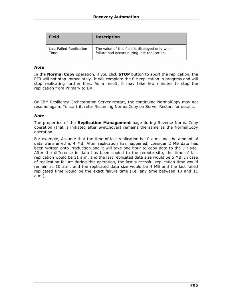
Recovery Automation
705
Field Description
Last Failed Replication Time
The value of this field is displayed only when failure had occurs during last replication.
Note
In the Normal Copy operation, if you click STOP button to abort the replication, the
PFR will not stop immediately. It will complete the file replication in progress and will
stop replicating further files. As a result, it may take few minutes to stop the
replication from Primary to DR.
On IBM Resiliency Orchestration Server restart, the continuing NormalCopy may not
resume again. To start it, refer Resuming NormalCopy on Server Restart for details.
Note
The properties of the Replication Management page during Reverse NormalCopy
operation (that is initiated after Switchover) remains the same as the NormalCopy
operation.
For example, Assume that the time of last replication is 10 a.m. and the amount of
data transferred is 4 MB. After replication has happened, consider 2 MB data has
been written onto Production and it will take one hour to copy data to the DR site.
After the difference in data has been copied to the remote site, the time of last
replication would be 11 a.m. and the last replicated data size would be 6 MB. In case
of replication failure during this operation, the last successful replication time would
remain as 10 a.m. and the replicated data size would be 4 MB and the last failed
replicated time would be the exact failure time (i.e. any time between 10 and 11
a.m.).
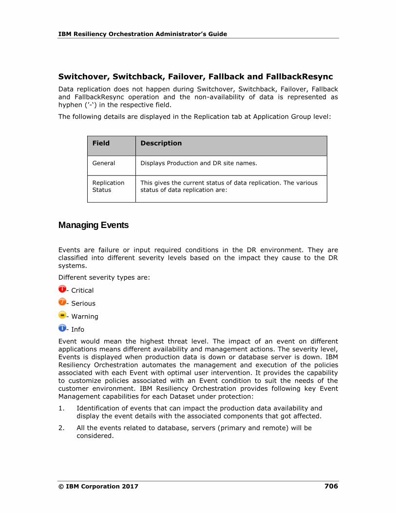
IBM Resiliency Orchestration Administrator’s Guide
© IBM Corporation 2017 706
Switchover, Switchback, Failover, Fallback and FallbackResync
Data replication does not happen during Switchover, Switchback, Failover, Fallback
and FallbackResync operation and the non-availability of data is represented as
hyphen (’-‘) in the respective field.
The following details are displayed in the Replication tab at Application Group level:
Field Description
General Displays Production and DR site names.
Replication Status
This gives the current status of data replication. The various status of data replication are:
Managing Events
Events are failure or input required conditions in the DR environment. They are
classified into different severity levels based on the impact they cause to the DR
systems.
Different severity types are:
- Critical
- Serious
- Warning
- Info
Event would mean the highest threat level. The impact of an event on different
applications means different availability and management actions. The severity level,
Events is displayed when production data is down or database server is down. IBM
Resiliency Orchestration automates the management and execution of the policies
associated with each Event with optimal user intervention. It provides the capability
to customize policies associated with an Event condition to suit the needs of the
customer environment. IBM Resiliency Orchestration provides following key Event
Management capabilities for each Dataset under protection:
1. Identification of events that can impact the production data availability and
display the event details with the associated components that got affected.
2. All the events related to database, servers (primary and remote) will be
considered.

Recovery Automation
707
3. Provide alerts and notifications to configured users. E-mail and SMS
notifications will be sent to group of users, associated with a database
(application).
4. Customized policy configuration for each Event to suit the customer
environment.
5. Automated triggers to initiate the pre-configured policies, in response to the
failure condition.
To see all occurred events for a specific group take the folowing steps.
1. Click DISCOVER > Groups on the navigation bar. The Groups page appears.
2. Click Recovery Group or Application Group tab, the respective Group
listing page appears.
3. Click the required group from the GROUP NAME column to configure the
workflow. The Group Details Page appears.
4. Click Group Configuration> Events.
The Events tab displays the following details of Events/ events that occurred with
IBM Resiliency Orchestration.
▪ EVENT ID
▪ EVENT DESCRIPTION
▪ EVENT SEVERITY
▪ EVENT IMPACT
▪ NOTIFY
When event is raised, it does the following:
▪ Interacts with users to notify respective users about the event.
▪ Alerts to send notification list.
▪ Enables Continuity Manager to perform continuity actions such as Failover,
Fallback etc.
▪ Enables RPO/ RTO Manager to report all events that have an impact on RPO
and RTO, etc.
An event may be associated to a policy. A policy is a series of actions (operations)
that are executed in a certain sequence based on configuration parameters. These
are primarily defined to contain the impact caused by the event.
Managing Events through Event Correlation
Event Correlation helps manage the polar events. Polar Events can be explained by
an example. A network down event and a network up event are polar to each other.
If the network down event is followed by a network up event, then the network down
event must be canceled according to Event Correlation.
Event Correlation performs the following:
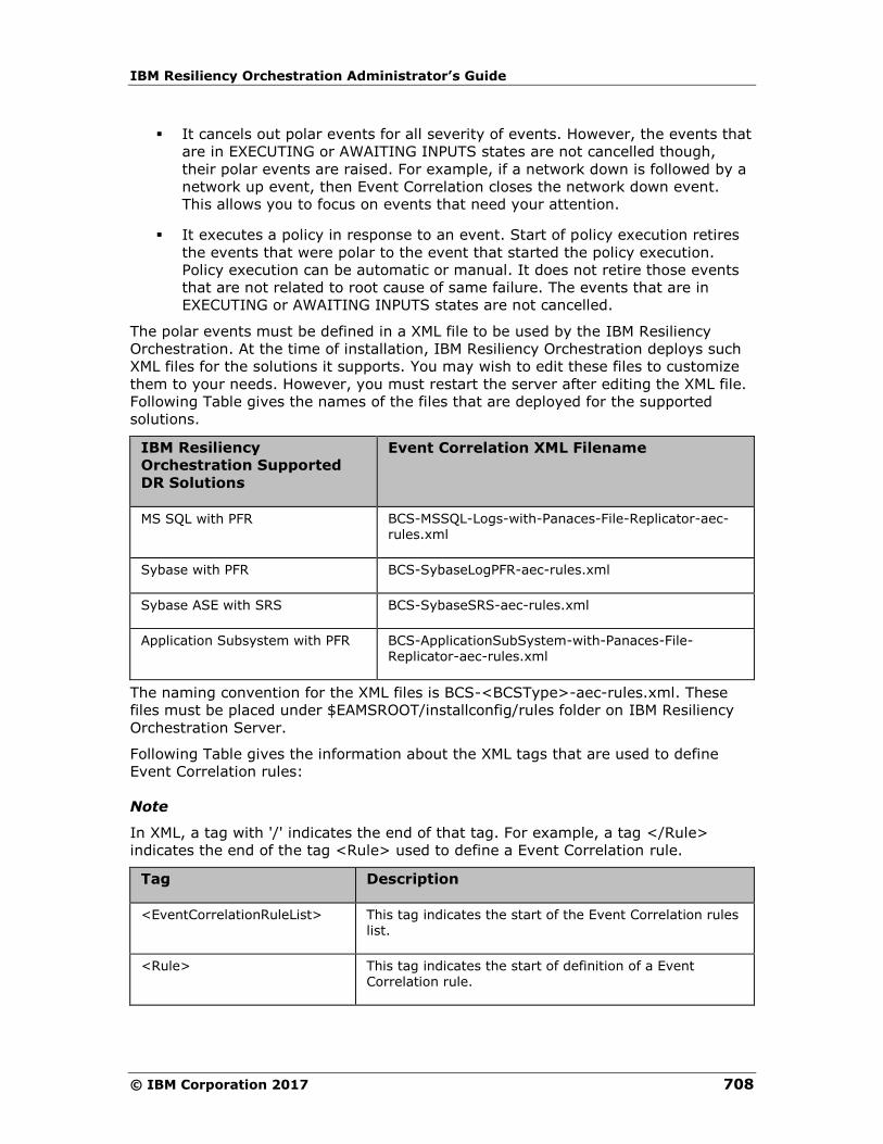
IBM Resiliency Orchestration Administrator’s Guide
© IBM Corporation 2017 708
▪ It cancels out polar events for all severity of events. However, the events that
are in EXECUTING or AWAITING INPUTS states are not cancelled though,
their polar events are raised. For example, if a network down is followed by a
network up event, then Event Correlation closes the network down event.
This allows you to focus on events that need your attention.
▪ It executes a policy in response to an event. Start of policy execution retires
the events that were polar to the event that started the policy execution.
Policy execution can be automatic or manual. It does not retire those events
that are not related to root cause of same failure. The events that are in
EXECUTING or AWAITING INPUTS states are not cancelled.
The polar events must be defined in a XML file to be used by the IBM Resiliency
Orchestration. At the time of installation, IBM Resiliency Orchestration deploys such
XML files for the solutions it supports. You may wish to edit these files to customize
them to your needs. However, you must restart the server after editing the XML file.
Following Table gives the names of the files that are deployed for the supported
solutions.
IBM Resiliency
Orchestration Supported
DR Solutions
Event Correlation XML Filename
MS SQL with PFR BCS-MSSQL-Logs-with-Panaces-File-Replicator-aec-rules.xml
Sybase with PFR BCS-SybaseLogPFR-aec-rules.xml
Sybase ASE with SRS BCS-SybaseSRS-aec-rules.xml
Application Subsystem with PFR BCS-ApplicationSubSystem-with-Panaces-File-Replicator-aec-rules.xml
The naming convention for the XML files is BCS-<BCSType>-aec-rules.xml. These
files must be placed under $EAMSROOT/installconfig/rules folder on IBM Resiliency
Orchestration Server.
Following Table gives the information about the XML tags that are used to define
Event Correlation rules:
Note
In XML, a tag with '/' indicates the end of that tag. For example, a tag </Rule>
indicates the end of the tag <Rule> used to define a Event Correlation rule.
Tag Description
<EventCorrelationRuleList> This tag indicates the start of the Event Correlation rules list.
<Rule> This tag indicates the start of definition of a Event Correlation rule.

Recovery Automation
709
Tag Description
<RuleType> This tag is used to specify the rule name you are going to define.
<InputEvent> This is used to specify the Event name that triggers the Event Correlation mechanism.
<PolarEvents> This tag indicates the start of the list of polar Events that are associated with <InputEvent>.
<PolarEvent> This tag specifies the name of the polar Event.
You may wish to do away with Event Correlation completely or partially . To disable
Event Correlation completely, you can do one of the following:
▪ Delete the XML file
▪ Take the back-up of the file in some other directory and remove it from the
current location or
▪ Delete the values specified for each tag.
To partially disable the unwanted rules in the XML file, do one of the following:
▪ Delete Rule
▪ Comment the rule tags
▪ Delete the tag values
List of Events based on severity can be classified as
Severity Events
Critical ▪ DR Related failure events like
o Replication failure for long time
o Server/App/DB down
▪ InfraFailures like
o Invalid credentials
o Remote server access failures
o Vault related failures
Serious ▪ SLA deviations like
o RPO deviation
o RTO deviation
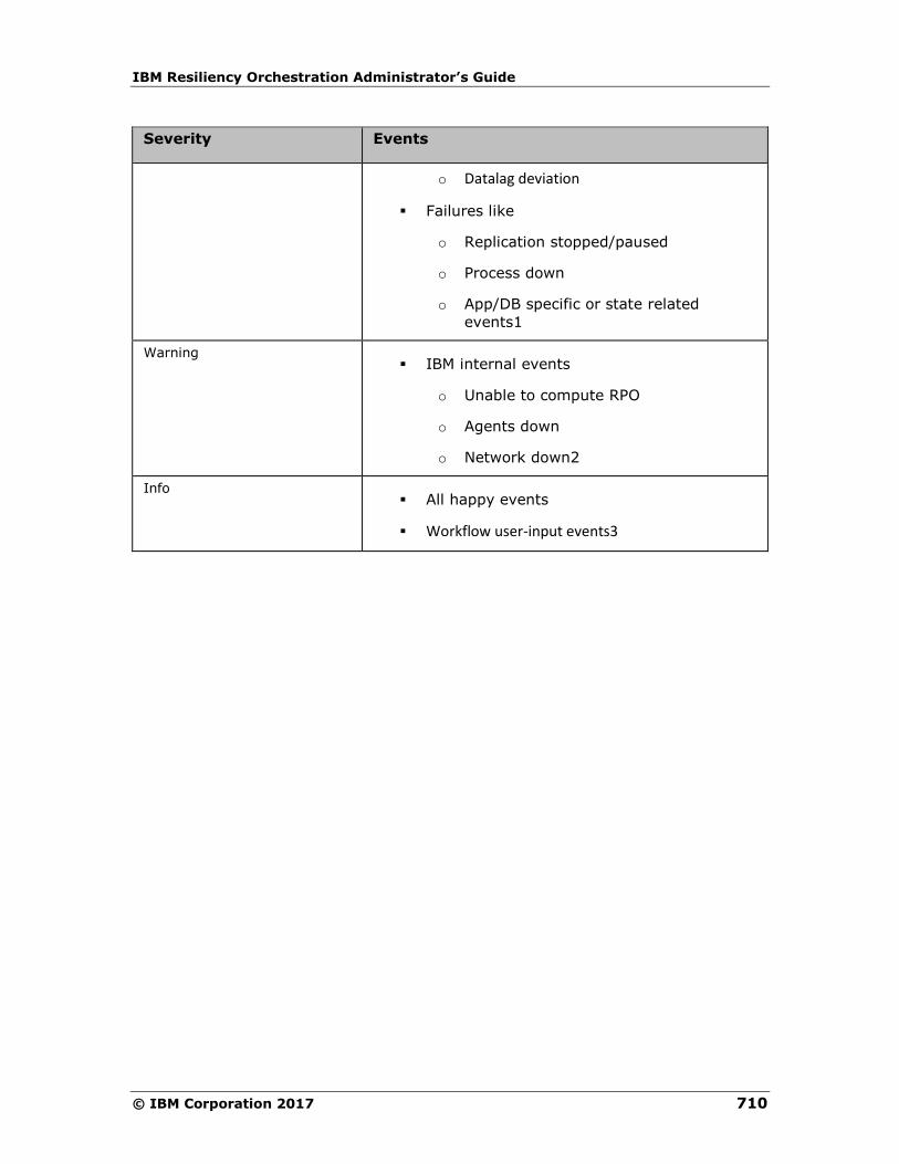
IBM Resiliency Orchestration Administrator’s Guide
© IBM Corporation 2017 710
Severity Events
o Datalag deviation
▪ Failures like
o Replication stopped/paused
o Process down
o App/DB specific or state related
events1
Warning ▪ IBM internal events
o Unable to compute RPO
o Agents down
o Network down2
Info ▪ All happy events
▪ Workflow user-input events3

Recovery Automation
711
Event Status
The interaction of Event Manager with others depends on the event status. The
following table lists possible status of an event:
Event Status Description
Open The status of an event is ‘Open’ only when the event is raised.
Notified An event for which notifications are sent to the
corresponding users through notification list.
For further details on notification list refer to Alerts topic.
Executing An event status is said to be ‘Executing’ only when a policy set for that event is under execution.
Some events may not have a policy set. In this case, this status is not applicable for that particular event.
Awaiting input The status change happens when the policy under execution requires user input.
Again this status is applicable for those events, which
have a policy associated to it.
Success An event status is successful when the policy under execution is successfully executed.
Failed An Event status is said to be ‘Failed’, when the policy under execution has failed.
Closed This state is manually set by the user when the associated problems are solved. But an event can be closed manually irrespective of the event status.
At any given point, only one instance of an event can be in open state and all other will be cancelled.
Event status is automatically updated by IBM Resiliency Orchestration in response to
the occurrence of above conditions.

IBM Resiliency Orchestration Administrator’s Guide
© IBM Corporation 2017 712
Synchronizing Date and Time between IBM Resiliency Orchestration Server and Client Machines
To adjust the Date and Time on client machines, perform the following steps:
1. Stop all Business Continuity Operations (BCO) including NormalCopy operation
on the Group(s) to which the machine belongs.
2. Move these Groups to Maintenance mode on IBM Resiliency Orchestration
Server.
3. Stop all agents on the machine.
4. Adjust the date/ time to be as close as possible to IBM Resiliency Orchestration
Server system time.
5. Restart all agents.
6. Restore Groups to Managed state.
7. Resume BCO operations on the Group(s).
To adjust Date and Time on IBM Resiliency Orchestration Server, perform the
following steps:
1. Stop all Business Continuity Operations (BCO) including NormalCopy operation
on all the Group(s).
2. Stop IBM Resiliency Orchestration Server.
3. Adjust the date/ time to clock time.
4. Restart IBM Resiliency Orchestration Server.
5. Resume BCO operations on all the Group(s).
713
Drills
Majority of the DR solutions fail at the time of disaster even with huge infrastructure
installation. This is either because there is no DR test plan in place or because the
plan is too complex or expensive to execute. Test Exercise provides complete
management control for performing DR test exercises and rehearsals. It provides
wizard based control to handle the exercises in an automated and reliable way.
IBM Resiliency Orchestration provides automated test exercise management for key
intrusive and non-intrusive tests. It provides following important capabilities:
▪ Individual FileSystem level test exercise execution and monitoring the status
of the same
▪ Automated execution of tests with wizard control for user intervention where
desired
▪ Intrusive test support – provides ‘Failover of the FileSystem’ test
▪ Non-intrusive test support – provides ‘DR FileSystem consistency and
integrity’ test
Each drill is pre-configured with a workflow to do the actual test and each of the
exercise is customized according to the your environment.
You have to execute the drills manually. IBM Resiliency Orchestration supports
executing multiple Drills in parallel. When Drills are being executed, allowing
continuity operations depends on the mode of the Drills you are executing. However,
Drills are not allowed, if the intended Group is under Unmanaged or Maintenance
mode.
The drills undergo different status during its life cycle. The possible values of status
are given in the following table:

IBM Resiliency Orchestration Administrator’s Guide
© IBM Corporation 2017 714
Status Description Next Possible Status
NEVER EXECUTED
The drills has never been executed so far.
START TEST
EXECUTING The drill is currently running. EXECUTING
SUCCESS The execution process has been successfully executed.
NO OPERATION
FAILED The execution process has
been failed.
STOP TEST/EXECUTING
AWAITING INPUT
The process is executing but requires user input. In this
case, there will be an action handler pop-up window requesting user input.
NO OPERATION
STOPPING This is an intermediate state indicating the drills in stopping. It goes in to this state when it is been manually triggered.
NO OPERATION
SHUTDOWN This occurs when IBM Resiliency Orchestration software or hardware fails or abnormal crash occurs.
NO OPERATION
The life cycle of the drills goes through seven processes. The initial state of the drills
is always NEVER EXECUTED.
Configuring Drills
Drills can be executed in any continuity state of a Group. It can be executed, while a
Business Continuity Operation (BCO) is running. If a drill interferes with a BCO, it
can impact the State of the System, BCOs, Group and Continuity health, and may
cause an Event.
Multiple drills can be run on Recovery Group simultaneously except for
Switchover/Switchback. However only one drill at a time can be executed on a
application Group.
During drill execution, the Group image will change to indicate that a drill is in
progress for that Group.

Drills
715
Click IBM Resiliency Orchestration Server User Role Management to see the
privileges.
To configure Drills, perform following steps:
1. Click DISCOVER > Groups on the navigation bar. The Groups page appears.
2. Click the Recovery Group tab, the Recovery Group Listing page appears.
3. Click the required group from the GROUP NAME column. The Group Details
Page appears.
4. Click the Group Configuration tab.
5. Click the Drills tab.
Switchover
The Switchover operation is performed to run the business from the DR site, i.e. the
remote server is made to function as primary (production) server and the primary is
made to function as remote server for a desired amount of time.
The Switchover operation can be executed after NormalFullCopy operation or by
manually stopping the NormalCopy. To manually stop the NormalCopy operation click
Stop NormalCopy button on the NormalCopy operation execution page.
To configure switchover follow the path:
Go to Drills > Summary > Group Name.
The Drill Listing page is displayed.
Click Switchover.
Click IBM Resiliency Orchestration Server User Role Management to see the
privileges.
Caution:
Disable the ‘Auto-Failover’ policy before initiating Switchover operation. To disable
the auto-failover policy, refer to the respective DR Solution book under DR Solutions
Supported by IBM Resiliency Orchestration.
During Switchover the BCM state is Switchover Transit.
The window elements after the Switchover has happened are same as the
NormalCopy Inactive BCM state except for a few things.
During Switchover Inactive state (i.e. after Switchover is complete) the Configured
properties and the Current properties differ i.e. the properties are interchanged.
For example consider the following configured properties:
Production Site: Mumbai
IBM Resiliency Orchestration Administrator’s Guide
© IBM Corporation 2017 716
Production Server: Windows 1
DR Site: Bangalore
Production Server: Windows 2
After Switchover operation, the following information is displayed in Current
Properties section.
Production Site: Bangalore
Production Server: Windows 2
DR Site: Mumbai
Production Server: Windows 1.
If the operation fails during Switchover Transit, then BCM state moves to Switchover
Inactive.
Note
For Switchover, auto-failover policies need to be manually switched to manual for
RG's that are part of an AG.
Switchback
This operation brings the configured primary server to production and configured DR
server to function as remote (standby) server. This setup is same as the NormalCopy
operation. Once the Switchback operation is performed, the NormalCopy is started
on the Group.
To start the Switchback operation perform the steps provided in Executing Drills
topic in this Help.
To configure switchback follow the path:
Go to Drills > Summary > Group Name.
The Drill Listing page is displayed
Click Switchback.
Click IBM Resiliency Orchestration Server User Role Management to see the
privileges.
Note
For Switchback, auto-failover policies need to be manually switched to manual for
RG's that are part of an AG.

Drills
717
Custom Drills
Customized drills can be added into or removed from IBM Resiliency Orchestration
dynamically. These drills can be created while creating a workflow. Such drills can be
added from Drills Dashboard page of a Recovery Group and Application Group.
Various actions can be imported into the customized test exercise using XML file
import. However, conventional method of configuring Drills by adding an action and
configuring it can also be followed.
To configure the Custom drills follow the path:
1. Click Drills on the navigation bar and click the Summary tab.
2. Click the desired Group Name. The Drill Listing page is displayed.
3. Click the custom drill.
Adding Drills
Click IBM Resiliency Orchestration Server User Role Management to see the
privileges.
To add a Drill:
1 Click Drills on the navigation bar and click the Summary tab.
2 Click the desired Group Name. The Drill Listing page is displayed.
Or
Click Discover>Groups on the navigation bar. Click Recovery Group tab and the
Recovery Group listing page appears. Click the desired group name from the Group
Name column. The Group Details Page appears. Click Drills on the sub navigation
bar. The Drills Listing Page is displayed.
3 Click Create New on the top right side of the page.
4 Enter Workflow Name in the text box and select Drill from the select Category
drop down list.
5 Click Create New.
Removing Drills
Click IBM Resiliency Orchestration Server User Role Management to see the
privileges.
Only customised test exercises can be deleted.
1 Click Drills on the navigation bar and click the Summary tab.
2 Click the desired Group Name. The Drill Listing page is displayed.
Or
Click Discover>Groups on the navigation bar. Click Recovery Group tab and the
Recovery Group listing page appears. Click the desired group name from the Group
Name column. The Group Details Page appears. Click Drills on the sub navigation
bar. The Drills Listing Page is displayed.

IBM Resiliency Orchestration Administrator’s Guide
© IBM Corporation 2017 718
3 Click corresponding to the customised drill to be deleted. A confirmation pop
up appears. Click Delete.
Configuring Drills
Click IBM Resiliency Orchestration Server User Role Management to see the
privileges.
1 Click Drills on the navigation bar and click the Summary tab.
2 Click the desired Group Name. The Drill Listing page is displayed.
Or
Click Discover>Groups on the navigation bar. Click Recovery Group tab and the
Recovery Group listing page appears. Click the desired group name from the Group
Name column. The Group Details Page appears. Click Drills on the sub navigation
bar. The Drills Listing Page is displayed.
3 Click on the Edit button against the desired test exercise you want to configure.
The Edit Workflow page appears.
4 You can configure the drill either by adding actions one by one or by importing a
XML file containing workflow of the exercise.

Drills
719
IntegrityCheck Test Place holder
Integrity Check is a default drill which is applicable for all the DR solutions. When a
RG is created, by default IntegrityCheck drill will be displayed on GUI in the below
two places:
To configure the Integrity Check follow the path:
Go to Drills > Summary > Group Name.
The Drill Listing page is displayed
Click Integrity Check.
or
1. Click DISCOVER > Groups on the navigation bar. The Groups page appears.
2. Click Recovery Group or Application Group tab, the respective Group
Listing page appears.
3. Click the required group from the GROUP NAME column. The Group Details
Page appears.
4. Click Group Configuration > Drills
IntegrityCheck drills cannot be deleted and this comes with “custom” action
configuration.
Note:
The report will be enabled only if the Banking Module is licensed.
Listing Drill Schedules
To list the schedule of all the drills configured for a Recovery Group, perform the
steps given below:
1. On the Navigation bar, click Drills> Summary.
2. Click on the Group name.
3. The Workflow Calender at the right displays the scheduled and ongoing
workflows.
4. On clicking the Workflow Calender, a table is displayed with the information on
Workflow, Group, Date Recurrence and Approvers.
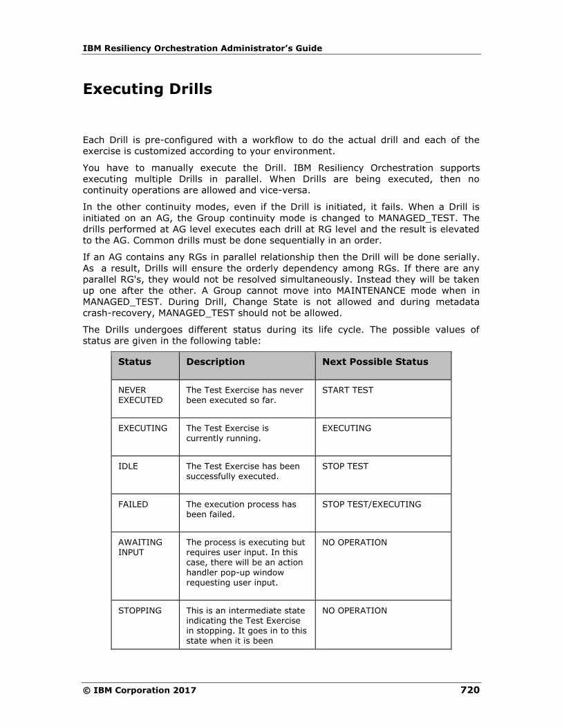
IBM Resiliency Orchestration Administrator’s Guide
© IBM Corporation 2017 720
Executing Drills
Each Drill is pre-configured with a workflow to do the actual drill and each of the
exercise is customized according to your environment.
You have to manually execute the Drill. IBM Resiliency Orchestration supports
executing multiple Drills in parallel. When Drills are being executed, then no
continuity operations are allowed and vice-versa.
In the other continuity modes, even if the Drill is initiated, it fails. When a Drill is
initiated on an AG, the Group continuity mode is changed to MANAGED_TEST. The
drills performed at AG level executes each drill at RG level and the result is elevated
to the AG. Common drills must be done sequentially in an order.
If an AG contains any RGs in parallel relationship then the Drill will be done serially.
As a result, Drills will ensure the orderly dependency among RGs. If there are any
parallel RG's, they would not be resolved simultaneously. Instead they will be taken
up one after the other. A Group cannot move into MAINTENANCE mode when in
MANAGED_TEST. During Drill, Change State is not allowed and during metadata
crash-recovery, MANAGED_TEST should not be allowed.
The Drills undergoes different status during its life cycle. The possible values of
status are given in the following table:
Status Description Next Possible Status
NEVER EXECUTED
The Test Exercise has never been executed so far.
START TEST
EXECUTING The Test Exercise is currently running.
EXECUTING
IDLE The Test Exercise has been successfully executed.
STOP TEST
FAILED The execution process has been failed.
STOP TEST/EXECUTING
AWAITING INPUT
The process is executing but requires user input. In this case, there will be an action
handler pop-up window requesting user input.
NO OPERATION
STOPPING This is an intermediate state indicating the Test Exercise in stopping. It goes in to this state when it is been
NO OPERATION
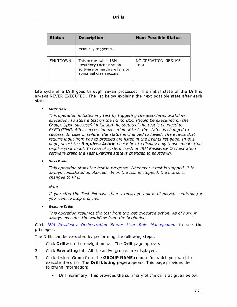
Drills
721
Status Description Next Possible Status
manually triggered.
SHUTDOWN This occurs when IBM Resiliency Orchestration
software or hardware fails or abnormal crash occurs.
NO OPERATION, RESUME TEST
Life cycle of a Drill goes through seven processes. The initial state of the Drill is
always NEVER EXECUTED. The list below explains the next possible state after each
state.
▪ Start Now
This operation initiates any test by triggering the associated workflow
execution. To start a test on the FG no BCO should be executing on the
Group. Upon successful initiation the status of the test is changed to
EXECUTING. After successful execution of test, the status is changed to
success. In case of failure, the status is changed to Failed. The events that
require input from you to proceed are listed in the Events list page. In this
page, select the Requires Action check box to display only those events that
require your input. In case of system crash or IBM Resiliency Orchestration
software crash the Test Exercise state is changed to shutdown.
▪ Stop Drills
This operation stops the test in progress. Whenever a test is stopped, it is
always considered as aborted. When the test is stopped, the status is
changed to FAIL.
Note
If you stop the Test Exercise then a message box is displayed confirming if
you want to stop it or not.
▪ Resume Drills
This operation resumes the test from the last executed action. As of now, it
always executes the workflow from the beginning.
Click IBM Resiliency Orchestration Server User Role Management to see the
privileges.
The Drills can be executed by performing the following steps:
1. Click Drill> on the navigation bar. The Drill page appears.
2. Click Executing tab. All the active groups are displayed.
3. Click desired Group from the GROUP NAME column for which you want to
execute the drills. The Drill Listing page appears. This page provides the
following information:
▪ Drill Summary: This provides the summary of the drills as given below:

IBM Resiliency Orchestration Administrator’s Guide
© IBM Corporation 2017 722
▪ Total Tests Run - Displays total number of drills that were run for the
group.
▪ Tests Successful - Displays total number of drills that were successfully
run for the group.
▪ Tests Failed - Displays total number of drills that were failed and not
successfully completed the execution.
▪ Next Scheduled- Schedule the execution for a later time.
List of Groups with the following information:
▪ DRILL NAME - List of configured drills for the Group
▪ STATUS - Displays the status of the drill.
▪ LAST INITIATED - Displays the last execution time of the respective
drills.
▪ ACTION - Displays option to Start or Stop or Resume the drills
execution.
4. Click the Start Test link in the ACTION column to initiate the corresponding
test exercise of the respective group. You can configure the test exercise by
clicking Configure link in the Action column.
5. Click icon of the respective Group to view the workflow details of the drill.
The Viewing Workflow Execution Status page appears.
6. Click Back to Details to go back to the Drills page.
Drills State
Based on the current state of the Group, Drills such as 'Initiate Switchover', 'Initiate
Switchback' etc are possible. These operations are listed as selectable buttons. The
complete list of operations is as given below:
Initiate Switchover This operation initiates Switchover operation on production and DR site. On completing the Switchover operation, the DR site becomes
production and production site becomes DR site.
Initiate Switchback This operation switches back the DR site to production and the production site to DR after the
Switchover operation.
Note:

Drills
723
In generic solutions, IBM Resiliency Orchestration provides facility to customize drills
as per your needs. In case of failure of an action, click Continue in the Workflow
Manager page to skip the failed action and to move to the next.
The following table lists the next possible operation based on the current state of
operation.
State Next Operation
Normal Reset Initiate NormalFullCopy, Change Continuity State, Move to Maintenance
Normal Inactive Initiate NormalCopy, Initiate Failover, Change Continuity State, Initiate Switchover, Move to Maintenance
Normal Transit -
Normal Active Stop NormalCopy
Normal Failed Initiate NormalCopy, Initiate Failover, Change Continuity State, Initiate Switchover, Move to Maintenance
Normal Degraded Stop NormalCopy
Switchover Inactive Change Continuity State, Initiate Reverse Copy, Initiate Failover, Initiate Switchback, Move to Maintenance.
Switchover Transit -
Switchover Active Stop Reverse Copy.
Switchover Failed Initiate NormalCopy, Initiate Switchover, Initiate
Failover, Change Continuity State
Failover Transit -
Failover Failed Initiate Failover, Initiate NormalCopy, Change Continuity State, Move to Maintenance
Failover Active Initiate Fallback, Change Continuity State, Move to
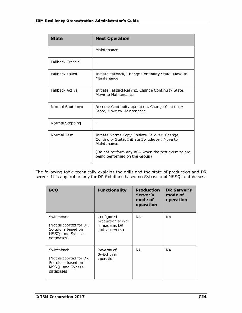
IBM Resiliency Orchestration Administrator’s Guide
© IBM Corporation 2017 724
State Next Operation
Maintenance
Fallback Transit -
Fallback Failed Initiate Fallback, Change Continuity State, Move to Maintenance
Fallback Active Initiate FallbackResync, Change Continuity State, Move to Maintenance
Normal Shutdown Resume Continuity operation, Change Continuity State, Move to Maintenance
Normal Stopping -
Normal Test Initiate NormalCopy, Initiate Failover, Change Continuity State, Initiate Switchover, Move to Maintenance
(Do not perform any BCO when the test exercise are being performed on the Group)
The following table technically explains the drills and the state of production and DR
server. It is applicable only for DR Solutions based on Sybase and MSSQL databases.
BCO Functionality Production
Server’s
mode of
operation
DR Server’s
mode of
operation
Switchover
(Not supported for DR Solutions based on
MSSQL and Sybase databases)
Configured production server is made as DR and vice-versa
NA NA
Switchback
(Not supported for DR
Solutions based on MSSQL and Sybase databases)
Reverse of Switchover operation
NA NA
Drills
725
Drill Listing
The Drill Listing page displays the following draft workflows. The user can also create
New Workflows.
The following are the twelve Draft workflows the user can select, namely
o Switchover
o Switchback
o Failover Exercise
o Remote Data Consistency
o StartAppPR
o StopAppPR
o RoleSwitchtoPR
o RoleswitchtoDR
o Recovery
o IntegrityCheck
Click on Edit to edit the workflow
Click on View to view the workflow.
Tracking Drills
You can track the Group on which Drill is running under Restricted or Unrestricted
mode. There are three following ways to track such Groups:
1. From the Drills Listing page
2. From the Drills Summary tab page
Click IBM Resiliency Orchestration Server User Role Management to see the
privileges.
To track the Group for a Drill from Drill Listing page, follow the steps given below:
3. In the navigation bar, click Drill> Executing.
4. In the Drills page, check the In Progress column against the desired Group.
It shows the number of drills being run on that Group.
To track the group for a Drill from Summary tab page, follow the steps given below:
IBM Resiliency Orchestration Administrator’s Guide
© IBM Corporation 2017 726
1. In the navigation bar, click Drill> Summary.
2. In the Summary page, check the WORKFLOW TYPE, CURRENT WORKFLOW,
and WORKFLOW STATUS columns for the desired Group. They give information
of whether or not a drills type of WORKFLOW TYPE is being executed on the
Group, its name and its execution status.
Changing Drills Mode
You can change the default Unrestricted mode of a drills to Restricted. To do this,
you need to edit a parameter value in the panaces.properties file.
Click IBM Resiliency Orchestration Server User Role Management to see the
privileges.
Follow the steps given below to change the mode:
1. On the IBM Resiliency Orchestration Server, go to the $EAMSROOT/installconfig
directory.
2. Open panaces.properties file.
3. Edit the value of panaces.testExerciseMode parameter. The value of 0 indicates
Restricted mode and 1 indicates the Unrestricted mode.
Drills Interfering with BCO
While Restricted mode does not allow executing Drills along with any BCO,
Unrestricted mode does.
However, caution must be taken while configuring and executing a drill so as not to
interfere with the running BCO. If an Unrestricted Drill interferes with a BCO, it can
impact the State of the System, the BCO, Group and Continuity health, and may
cause an Event.
A Failover drill being executed at the time of Normal Copy operation is the simplest
example of a drill interfering with a BCO. Such execution can cause the Normal Copy
to fail.
Identifying Group under Unrestricted Test Mode
Unrestricted Test Exercise (UTE) allows you to execute a drill in any continuity state
of a Group. It can be run while a Business Continuity Operation (BCO) is running.
When a UTE is running for a Group, it does not put under TEST mode. As a result,
the Group health is not changed. During UTE, the Group image does not change to
indicate that an Unrestricted Test Exercise is in progress for that Group. This makes
it difficult to identify the Group on which UTE is being run.
Drills
727
Click IBM Resiliency Orchestration Server User Role Management to see the
privileges.
Follow the steps given below to identify such Groups:
1. Click Monitor or Manage on the navigation bar.
2. Click Executing Workflow.
3. In the Recovery Group Listing window, check WORKFLOW TYPE, WORKFLOW
DETAILS, and STATUS columns for the desired Group.
A Group with a UTE running on it will have WORKFLOW TYPE as Test Exercise,
WORKFLOW DETAILS will display the details of the workflow being executed, and
STATUS column will show the execution of the workflow of the Drills.
Effect of Drills on Group Status
In IBM Resiliency Orchestration, the Group mode changes are based on the mode of
Drills being run on it. If Restricted mode of Drills is running on a Group, the Group is
put under MANAGED_TEST mode. However, if Unrestricted mode of Drills is running
on a Group, the Group mode does not change. This makes it difficult to identify the
Group on which Unrestricted Test Exercise (UTE) is being run.
Viewing Drills
To view the Drills summary for a list of Groups, on the Navigation Bar, click
Drills> Summary > Group Name. You can also view from the Dashboard, by
clicking Drill.
Click IBM Resiliency Orchestration Server User Role Management to see the
privileges.
The Drills page has the following tabs:
▪ Executing
▪ Scheduled
▪ Summary
Viewing Drills for a Group
Click IBM Resiliency Orchestration Server User Role Management to see the
privileges.
This page will list all the Drills configured for a Group. The details displayed are:
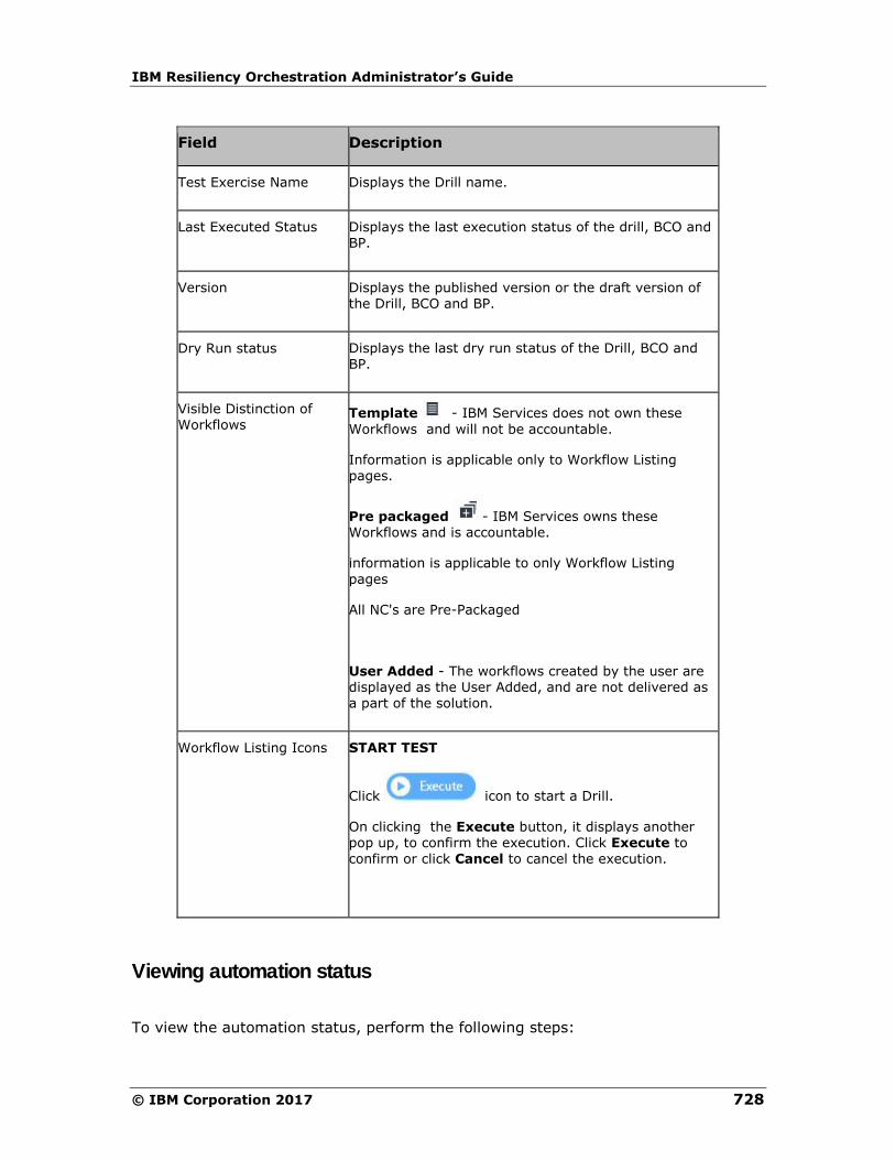
IBM Resiliency Orchestration Administrator’s Guide
© IBM Corporation 2017 728
Field Description
Test Exercise Name Displays the Drill name.
Last Executed Status Displays the last execution status of the drill, BCO and BP.
Version Displays the published version or the draft version of the Drill, BCO and BP.
Dry Run status Displays the last dry run status of the Drill, BCO and
BP.
Visible Distinction of Workflows
Template - IBM Services does not own these
Workflows and will not be accountable.
Information is applicable only to Workflow Listing pages.
Pre packaged - IBM Services owns these Workflows and is accountable.
information is applicable to only Workflow Listing
pages
All NC's are Pre-Packaged
User Added - The workflows created by the user are displayed as the User Added, and are not delivered as a part of the solution.
Workflow Listing Icons START TEST
Click icon to start a Drill.
On clicking the Execute button, it displays another pop up, to confirm the execution. Click Execute to
confirm or click Cancel to cancel the execution.
Viewing automation status
To view the automation status, perform the following steps:
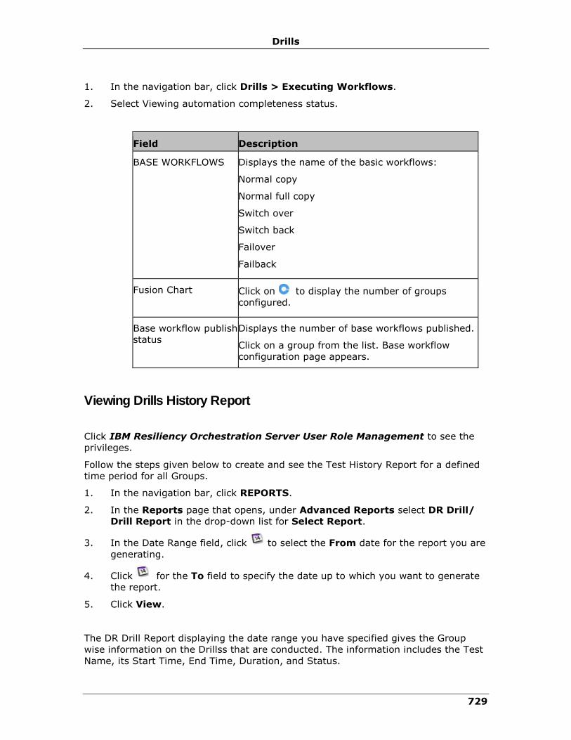
Drills
729
1. In the navigation bar, click Drills > Executing Workflows.
2. Select Viewing automation completeness status.
Field Description
BASE WORKFLOWS Displays the name of the basic workflows:
Normal copy
Normal full copy
Switch over
Switch back
Failover
Failback
Fusion Chart Click on to display the number of groups
configured.
Base workflow publish
status
Displays the number of base workflows published.
Click on a group from the list. Base workflow
configuration page appears.
Viewing Drills History Report
Click IBM Resiliency Orchestration Server User Role Management to see the
privileges.
Follow the steps given below to create and see the Test History Report for a defined
time period for all Groups.
1. In the navigation bar, click REPORTS.
2. In the Reports page that opens, under Advanced Reports select DR Drill/
Drill Report in the drop-down list for Select Report.
3. In the Date Range field, click to select the From date for the report you are
generating.
4. Click for the To field to specify the date up to which you want to generate
the report.
5. Click View.
The DR Drill Report displaying the date range you have specified gives the Group
wise information on the Drillss that are conducted. The information includes the Test
Name, its Start Time, End Time, Duration, and Status.
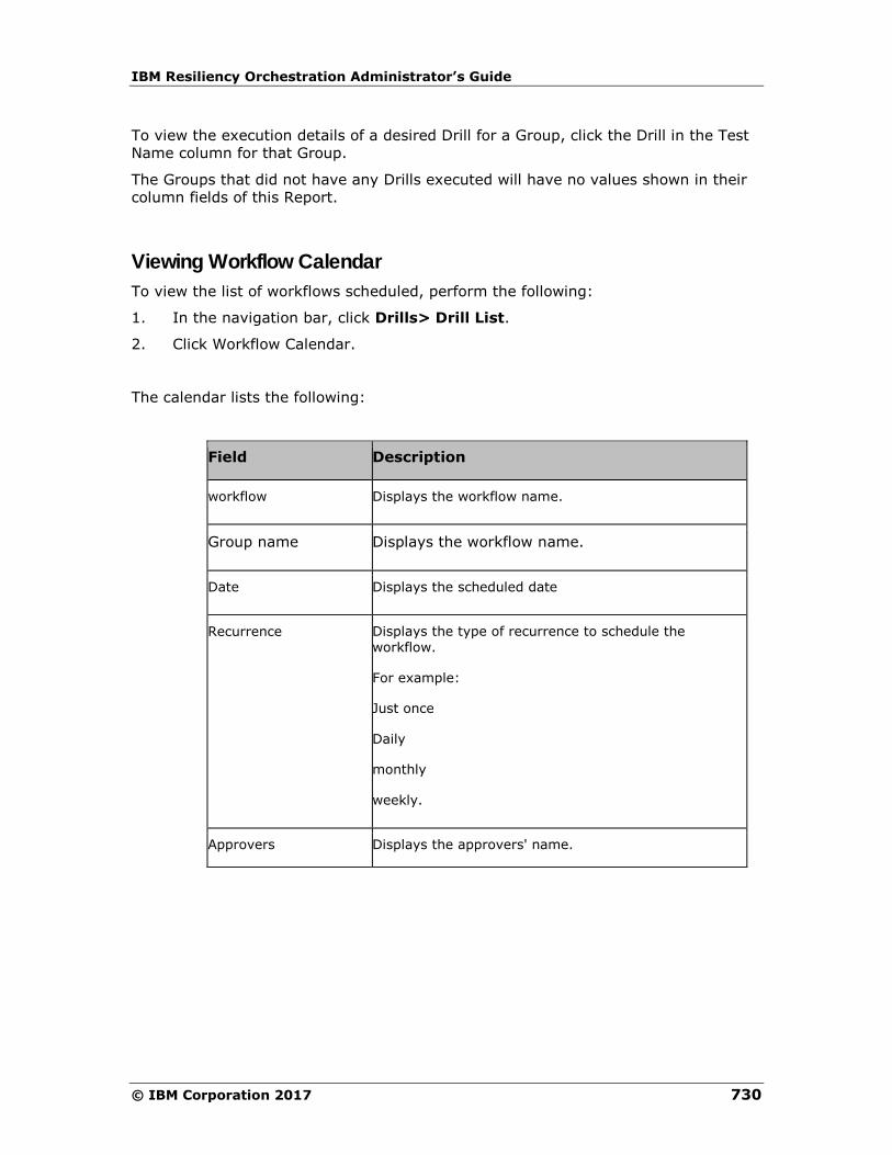
IBM Resiliency Orchestration Administrator’s Guide
© IBM Corporation 2017 730
To view the execution details of a desired Drill for a Group, click the Drill in the Test
Name column for that Group.
The Groups that did not have any Drills executed will have no values shown in their
column fields of this Report.
Viewing Workflow Calendar
To view the list of workflows scheduled, perform the following:
1. In the navigation bar, click Drills> Drill List.
2. Click Workflow Calendar.
The calendar lists the following:
Field Description
workflow Displays the workflow name.
Group name Displays the workflow name.
Date Displays the scheduled date
Recurrence Displays the type of recurrence to schedule the workflow.
For example:
Just once
Daily
monthly
weekly.
Approvers Displays the approvers' name.

Drills
731
Viewing Recent Execution Drills Status
Click IBM Resiliency Orchestration Server User Role Management to see the
privileges.
The detailed status of a drills can be seen separately from following two pages:
To view the details of the desired drills from the DR Drill/ Drills Report page,
follow the steps given below:
1. Generate the Drills Report for desired period of time.
2. In the generated report, for the desired Group, click the desired Drills in the
Drills column of the report.
3. This displays the detailed status of the Drills in Recent Execution Status
page.
To view the details of the desired Drills from the Drills page, follow the steps given
below:
1. On the navigation bar, click Drills > Summary. This opens the Drills page
that displays Group wise summary of the Drills.
2. Click desired Group under GROUP NAME column for which you want to see the
Workflows.
3. In the Group Workflow page that appears, click for the desired Drills to
view the detailed recent execution status of the Drills.
Drills Management
Majority of the DR solutions fail at the time of disaster even with huge infrastructure.
This is either because there is no DR test plan in place or because it is too complex
or expensive to execute. The Drills provides complete management control for
performing DR drills and rehearsals. It provides wizard based control to handle the
exercises in an automated and reliable method.
IBM Resiliency Orchestration provides automated drills management for key intrusive
and non-intrusive drills . It provides the following important capabilities:
▪ Individual FileSystem level drills execution and monitoring the status of the
same.
▪ Automated execution of drills with wizard control for user intervention where
desired.
▪ Intrusive drills support – provides ‘Failover of the FileSystem’ drills.
▪ Non-intrusive drill support – provides ‘DR FileSystem consistency and
integrity’ drills.
You can view list of drills configured for a group by clicking Drills on the Navigation
bar. The Drills page appears. This page provides the following information:
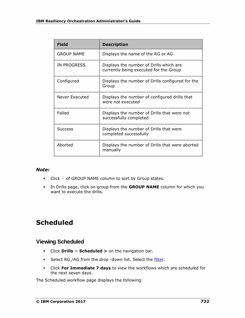
IBM Resiliency Orchestration Administrator’s Guide
© IBM Corporation 2017 732
Field Description
GROUP NAME Displays the name of the RG or AG
IN PROGRESS Displays the number of Drills which are
currently being executed for the Group
Configured Displays the number of Drills configured for the
Group
Never Executed Displays the number of configured drills that
were not executed
Failed Displays the number of Drills that were not
successfully completed
Success Displays the number of Drills that were
completed successfully
Aborted Displays the number of Drills that were aborted
manually
Note:
▪ Click of GROUP NAME column to sort by Group states.
▪ In Drills page, click on group from the GROUP NAME column for which you
want to execute the drills.
Scheduled
Viewing Scheduled
▪ Click Drills > Scheduled > on the navigation bar.
▪ Select RG /AG from the drop -down list. Select the filter.
▪ Click For Immediate 7 days to view the workflows which are scheduled for
the next seven days.
The Scheduled workflow page displays the following:
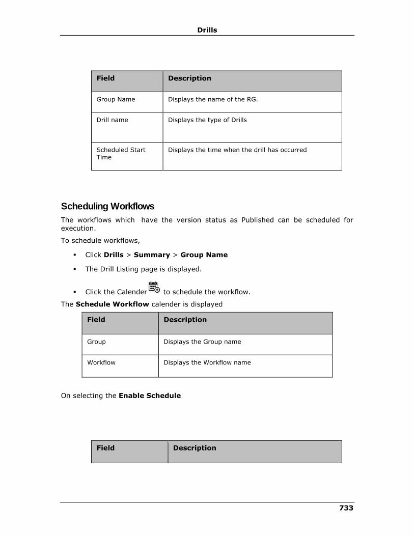
Drills
733
Field Description
Group Name Displays the name of the RG.
Drill name Displays the type of Drills
Scheduled Start Time
Displays the time when the drill has occurred
Scheduling Workflows
The workflows which have the version status as Published can be scheduled for
execution.
To schedule workflows,
▪ Click Drills > Summary > Group Name
▪ The Drill Listing page is displayed.
▪ Click the Calender to schedule the workflow.
The Schedule Workflow calender is displayed
Field Description
Group Displays the Group name
Workflow Displays the Workflow name
On selecting the Enable Schedule
Field Description
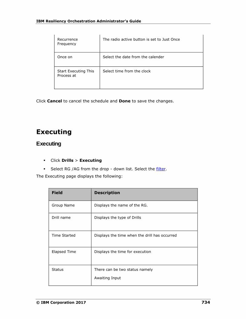
IBM Resiliency Orchestration Administrator’s Guide
© IBM Corporation 2017 734
Recurrence Frequency
The radio active button is set to Just Once
Once on Select the date from the calender
Start Executing This Process at
Select time from the clock
Click Cancel to cancel the schedule and Done to save the changes.
Executing
Executing
▪ Click Drills > Executing
▪ Select RG /AG from the drop - down list. Select the filter.
The Executing page displays the following:
Field Description
Group Name Displays the name of the RG.
Drill name Displays the type of Drills
Time Started Displays the time when the drill has occurred
Elapsed Time Displays the time for execution
Status There can be two status namely
Awaiting Input

Drills
735
Field Description
Executing
On clicking the group name, the Drill listing page is displayed.
On clicking the status, the Execution page of the workflow is displayed. The following
information is displayed in the execution workflow page.
Field Description
Group Name Displays the name of the RG.
Workflow Name Displays the workflow name along with the version
Start Time Displays the time when the drill has occurred
Time Elapsed Displays the time for execution
Status There can be five status namely
▪ Awaiting Input
▪ Executing
▪ Success
▪ Failed
▪ Aborted
The next table displays information at the RAL level.
Field Description
Action Displays the RAL action
Time initiated Displays the time the execution has started

IBM Resiliency Orchestration Administrator’s Guide
© IBM Corporation 2017 736
Field Description
Time Elapsed Displays the time of execution of the RAL
Status The status can be
▪ Awaiting input
▪ Unable to execute
▪ Success
▪ Crashed
▪ Aborted
Click on Key Value Pairs to view the key values in the execution page.
Click on Export to CSV to export the workflow.
Summary
Viewing Summary
To view the summary for a list of Groups, on the Navigation Bar, click Drills>
Summary> Group Name. You can also view from the Dashboard, by clicking
Drills.
The user can select either the recovery groups or Application groups from the drop -
down list. Filter is set to Type I by default. The continuity status is represented by
the color beside the group name.
The Summary tab has the following fields:
Field Description
Group name Displays the name of the Recovery Group or Application Group
Drafts Displays the state of the workflow
Published Displays the workflow

Drills
737
Field Description
Executing Displays the number of configured drills that are being executed
Last Executed Displays the date and time when the last execution has successfully been completed.
Next Scheduled Displays the date for the next drill
Click View all to view all the Recovery groups.
Note:
Click of GROUP NAME column to sort by group states.
Select Workflow
Click Drills > Summary > Group Name.
The Drills Listing page is displayed.
Click Create New.
The Select workflow tab is displayed.
▪ Click on to edit the workflow.
▪ Click on to view the Remote Check Preview page.
Viewing workflow details
To view the workflow details, perform the following:
1. In the navigation bar, click Drill> Summary.
2. Select the group.
3. The Drill Listing page displays the following information:
Current State:
Field Description
Current state Displays the current status of the workflow.
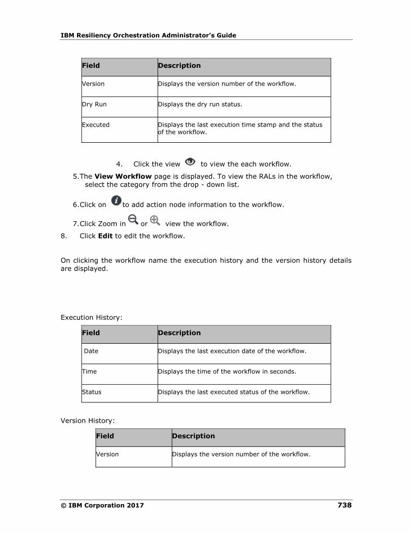
IBM Resiliency Orchestration Administrator’s Guide
© IBM Corporation 2017 738
Field Description
Version Displays the version number of the workflow.
Dry Run Displays the dry run status.
Executed Displays the last execution time stamp and the status of the workflow.
4. Click the view to view the each workflow.
5. The View Workflow page is displayed. To view the RALs in the workflow,
select the category from the drop - down list.
6. Click on to add action node information to the workflow.
7. Click Zoom in or view the workflow.
8. Click Edit to edit the workflow.
On clicking the workflow name the execution history and the version history details
are displayed.
Execution History:
Field Description
Date Displays the last execution date of the workflow.
Time Displays the time of the workflow in seconds.
Status Displays the last executed status of the workflow.
Version History:
Field Description
Version Displays the version number of the workflow.

Drills
739
Created ON Displays the date creation of the workflow.
Created BY Displays the user name, who created the workflow.
Executed Displays the last execution status.
Editing Workflows
▪ Click Drills > Summary > Group Name > > View Workflows.
▪ Click Edit.
On clicking Edit more actions can be carried out to the workflows.
▪ Click on ADD to include Actions, Action Groups, Workflows into the
workflow
▪ On selection of Actions the Replication category drop - down list is displayed
▪ Click the drop - down list to choose any category
▪ Click on to add a new action node
▪ Click Show all RALs to view all the RALs which opens the RAL Library.
▪ On selection of the Action Groups, the Show all RALs is highlighted. On
clicking it, the RAL Library is displayed.
▪ On selection of the Workflows, the user can select a signature solution from
the Select Signature Solution from the drop -down list. Click Import
Workflow to browse for the workflow files.
▪ Click to copy the node
▪ Click to delete the node
▪ Click on icon to add a fork node. It is used to execute actions in parallel.
▪ Click on icon to add a join node. It is used to wait for executed forked
actions.
▪ Click to rearrange the workflow.
▪ Click Key-Value List to Add key Value.
IBM Resiliency Orchestration Administrator’s Guide
© IBM Corporation 2017 740
▪ Click Save Now to save the Workflow
▪ Click Export. A popup window is displayed. Click No to cancel the action and
Yes to export the workflow.
▪ Click Next to Publish Workflow.
Viewing Published workflow by logged in user
Viewing Published workflow by logged in user
These published workflow can be viewed in the following ways.
From the Summary page, Executing page and Scheduled page:
1. Click the Summary, Executing or Scheduled tab from the Drills page.
2. Click on the specific group name. The Drills Listing page appears.
3. Click the Workflow Published by You button on the right of the page to view
the workflows published by the logged in user.
OR
1. Click the Drill name in the Drills Listing page. The drill history details page
appears.
2. Click the Workflow Published by You button on the right of the page to view
the workflows published by the logged in user.
741
Working with Workflow Manager
Working with Workflow Manager
Workflow is a sequence of steps/tasks performed to complete a business process.
The business process could be a Business Continuity Operation or DR Drill or EOD
operation.
Actions and workflows are a set of procedures that are configured to act against an
event in the DR environment. You cannot add or delete an Action from a Workflow
when it is being executed.
Workflow manager enables you to design the workflow logic, execute and view the
execution status.
Configuring the workflow involves:
▪ Design the workflow logic
- Insert/delete actions to be performed
- Provide/alter inputs to the actions
▪ Flow control
- Conditions to quit/abort workflow
- Handle failure conditions
- Recursion (execute an action periodically)
▪ Scheduling the workflow
Executing the workflow involves:
▪ Execute (start/stop) workflow
▪ Schedule workflow
Execution Status:
▪ Show execution status

IBM Resiliency Orchestration Administrator’s Guide
© IBM Corporation 2017 742
System Workflows:
IBM Resiliency Orchestration will execute certain workflow(s) periodically based on
the DR solution for monitoring. Such workflows are called System workflows.
Workflow Execution Page
Clicking the Executing or Awaiting Input link in the Execution Status column will
navigate the user to the workflow execution page. This page will display the
information in the following table.
▪ Click the Show Canvas button to view the workflow details by loading the
canvas.
▪ Click zoom in to make the canvas bigger.
▪ Click zoom out to make the canvas smaller.
Field Description
Action Displays the name of the action.
TIME INITIATED Displays the exact start time of the action
execution.
TIME ELAPSED (SEC) Displays the time calculated from the process of
initiation to completion of the action.
TYPE Displays the type of action.
STATUS DETAILS Displays the status details of the action
execution.
Note:
1 If the status is in EXECUTING mode, the
user can click on the EXECUTING link to view
Continue as Success or Continue as Failure
option buttons. Depending on the requirement
and by giving a reason, select any one of the
option.
2 If the Status is Awaiting Input, depending
on the requirement, user can select any one of
the below options:
3 Continue as Success
4 Continue as Failure
5 Retry
Working with Workflow Manager
743
Field Description
6 Quit
If user wants to know the reason for Awaiting
Input, click the View action log button.
7 Click on any link corresponding to desired
action to view the following details for the action.
8 DB Logs
9 Tail Logs
10 Sys Logs
Resuming workflow after IBM Server failure
If IBM Resiliency Orchestration server fails due to hardware, network or other
problems, all workflows being executed also stops. When the server is up again, the
failed workflows can be resumed automatically or manually, depending on the
presence of recurring actions in it.
Note
When IBM Resiliency Orchestration server is up, if a workflow contains at least one
recurring action, the complete workflow is resumed from the start.
For a workflow that does not have any recurring actions, you need to take a decision
on its further execution. To do so, perform the following steps:
1. Click Manage> Recovery Groups > Group Name > on the navigation bar. The
Recovery Groups details page appears.
2. Click the Execute button for the workflow in the Continuity Workflows section.
3. Click the Resume button to continue the operation. UserInputRequired004
event will be raised and will be shown in the event banner indicating that user
intervention is required.
4. Click the Provide Input link on the Event Banner to open the Action Execution
Handler page. In the Workflow Execution Section on the right, do any one of
the following.
• Click Start to restart the Workflow from the beginning.
• Click Skip As Success to skip the current action considering it to be
successfully executed and continue with the next action.
• Click Skip As Failure to skip the current action considering it to be failed and
continue with the next action. The next action will be that pointed to by the
Failure path of the current failed action, not the normal Success path. If the
failure path of the failed action is pointing to “None” then the workflow will
terminate.
IBM Resiliency Orchestration Administrator’s Guide
© IBM Corporation 2017 744
• Click Resume to continue executing the current action.
• Click Quit to stop workflow execution. The complete workflow terminates
without executing any more actions.
Dealing with Failures of Workflow Execution
When certain action's execution is failed, you can view the action failure details in
the Recent Execution Status window.
To open the Recent Execution Status window:
1. Click the icon to view the events waiting for user input. All actions which
are configured to be informed are displayed here.
2. Click the Provide Input link for the event requiring your inputs. The Recent
Execution Status page appears.
In Workflow Graph & Inputs tab:
▪ In case of Action Execution Failed:
▪ Click Retry to retry the execution of the failed action.
▪ Click Continue to execute the next action. The next action will be that
pointed to by the Failure path of the current failed action, not the
normal Success path. If the failure path of the failed action is pointing
to None then the workflow will terminate.
▪ Click Quit to stop workflow execution. The complete workflow
terminates without executing any more actions.
▪ In case of Workflow Execution Recovery:
▪ Click Start to restart the Workflow from the beginning.
▪ Click Skip As Success to skip the action as success and continue with
next action.
▪ Click Skip As Failure to skip the action as failure and continue with
next action.
▪ Click Resume to continue executing the current action.
▪ Click Abort to abort executing Workflow.
Limitation:
Skip As Success and Skip As Failure features do not work if we configure Time to
execute property. Time to execute property is used to wait, before execution.
Working with Workflow Manager
745
Stopping Workflows
Workflows will be stopped only after completing the execution of current
action/action group. If there are any user input required by the action, then the
workflow will stop only after the input is provided.
The following is the behavior of stopping workflows with various configurations:
Action: If the action is executing, workflow will stop only after its completion.
1. Time To Execute (Wait): If this property is set, the action will wait for the
configured time before it actually performs the task. Workflow will stop only
after the action completes the Wait and performs the actual task.
i. Execution mode Manual: If this property is "Manual", then the action
will notify the user before performing the actual task.
▪ Clicking Continue will stop the workflow after performing the actual
task
▪ Clicking Quit will stop the workflow immediately without performing
the actual task
ii. Inform on Completion: If this property is set, then the action will notify
the user after the actual task. Workflow will stop only after clicking
"Continue" or "Quit". However, if this is a "retryable" action then
clicking on "Retry" will execute the action again. [For more information
on "Inform completion" and "Is Retryable" options, refer to
Configuring Actions.
2. Action Group: If the action group is executing, the workflow will stop only
after completing all actions in the action group.
If execution of an action within the action group results in abort of workflow, then no
further actions within action group will be executed. For example, clicking "Quit" in
"Execution Mode Manual" or "Inform Completion" for the action.
If there are multiple actions waiting for user input, then clicking "Quit" for one of the
actions will only complete that action/action group, but not the workflow. You need
to click "Quit" on all the actions that are waiting for user input for the workflow to
stop. For example, when "dump log" and "apply log" recurring actions need user
input, then clicking on "Quit" for "dump log" will complete only dump log but not
"apply log" action. Clicking on "Quit" on the "apply log" will stop the workflow. Any
workflow in progress can be aborted by clicking the "Abort" link on the Workflow
Execution Status page.
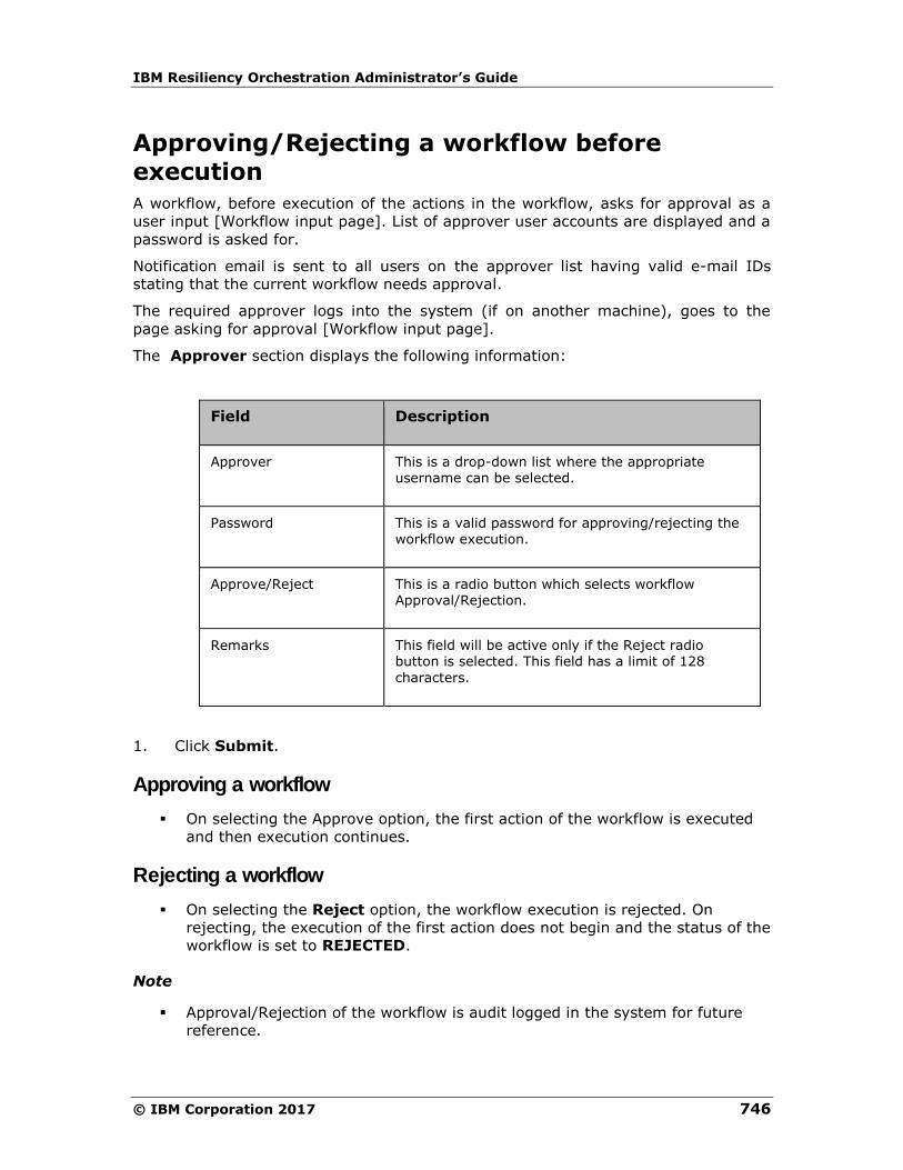
IBM Resiliency Orchestration Administrator’s Guide
© IBM Corporation 2017 746
Approving/Rejecting a workflow before
execution
A workflow, before execution of the actions in the workflow, asks for approval as a
user input [Workflow input page]. List of approver user accounts are displayed and a
password is asked for.
Notification email is sent to all users on the approver list having valid e-mail IDs
stating that the current workflow needs approval.
The required approver logs into the system (if on another machine), goes to the
page asking for approval [Workflow input page].
The Approver section displays the following information:
Field Description
Approver This is a drop-down list where the appropriate username can be selected.
Password This is a valid password for approving/rejecting the workflow execution.
Approve/Reject This is a radio button which selects workflow Approval/Rejection.
Remarks This field will be active only if the Reject radio button is selected. This field has a limit of 128
characters.
1. Click Submit.
Approving a workflow
▪ On selecting the Approve option, the first action of the workflow is executed
and then execution continues.
Rejecting a workflow
▪ On selecting the Reject option, the workflow execution is rejected. On
rejecting, the execution of the first action does not begin and the status of the
workflow is set to REJECTED.
Note
▪ Approval/Rejection of the workflow is audit logged in the system for future
reference.
Working with Workflow Manager
747
DryRun
Dry Run is a feature that test the checks the execution of a workflow. The aim
of the dry run is:
1. To ensure that the user has correctly configured the workflow with the right
sequence of actions and the inputs accurately defined.
2. To verify any changes made in the user configuration.
The result of the dry run is available in a report that provides the necessary
information. Any issues are identified with warnings or errors. The details are
dependent on the RAL. The report includes:
▪ Executed actions and their sequence.
▪ Server details.
▪ Input configuration values for the action.
▪ List of commands that are executed on the target server.
▪ List of input/ output keys and parameters.
▪ Pre-checks.
Note
You can view the available pre-check details of the individual RAL action, found in
Recovery Automation Library.
Mode
Actions can execute non-intrusive commands that does not change the state of the
system, such as check database state and check existence of file or directory. This is
the only mode of dry run execution and it is known as Dry Run with Pre-checks.
Process
When a dry run is executed, each action (that supports the dry run feature) of the
workflow runs in a manner that does not actually execute the command but logs the
final command or set of commands that are executed. Each action also logs other
supporting information, such as a list of checks. The result of the dry run is a
workflow execution report, similar to the real execution report along with added
information to assist the user in obtaining detailed information about the workflow.
Note:
The RAL actions that support dry run are enhanced to return information for the
reports. Not all RAL actions support this feature. For actions that do not support, logs
indicate the general information, such as server details and input configuration
values.
IBM Resiliency Orchestration Administrator’s Guide
© IBM Corporation 2017 748
Workflow Enhancements
Confirmation of Workflow Execution
1. After publishing a workflow an Execute button is displayed against each
workflow.
2. On clicking Execute , a confirmation pop-up is displayed with
Execute and Cancel.
3. Click Execute to execute the workflow.
4. Click Cancel to cancel the workflow.
After clicking the execute button the execution status bar is displayed by replacing
the listing icons. The status bar displays the executing RAL count.
Click the Executing link under Execution Status column of the workflow to navigate
to the workflow execution page.
Dryrun Execution
After publishing a workflow, Dryrun icon is displayed against the workflow.
On clicking Dryrun , a confirmation pop up is displayed with Dryrun and
Cancel. Click Dryrun to execute or click Cancel to cancel the Dryrun.
On clicking Dryrun it displays a spinner by replacing all the other icons such as Edit
and Delete.
When the Dryrun of a workflow is executing, the Dryrun count is displayed under the
Dryrun status column against the workflow.
Nested Workflow (Navigation to Workflow within a Workflow)
"Workflow Calling Workflow" enables the user to call sub workflows from the main
workflow execution page.
After configuring the workflow calling workflow, a nested workflow link is displayed in
the main execution page. Clicking the nested workflow link will navigate to the sub
workflow execution page.
From the sub workflow execution page, the user can navigate to the main workflow
execution page by clicking on parent workflow name on the breadcrumb.
Working with Workflow Manager
749
View Workflows
Click on the View icon against the workflow.
The view workflow page is displayed. In this page the user can only view (Read only)
RALs. The user cannot modify any values in the view workflow page.
Click on the edit icon in the view workflow page. The user is enabled now to navigate
to the Workflow Editor page.
Workflows Visual Distinction
The workflows are categorized into three types namely
1. Prepackaged
2. Template and
3. User Added
Pre-Packaged: These workflows are owned and shipped by IBM.
Template: Template is a workflow that can be used with modifications as per the
requirements.
User Added: The workflows created on the field by the user.
Stopping/Aborting Parent Workflows
While stopping/aborting the parent workflow, the child workflows are stopped.
Propagation of Nested Workflow Status
The child workflow status needs to be displayed in the parent workflow during all
stages: preexecution, execution, and post execution.
Parent Workflow Summary Counts
The following counts of parent workflow execution include the actions count of child
workflows:
▪ Completed steps
▪ Total steps
▪ Failed steps
▪ Not executed steps
IBM Resiliency Orchestration Administrator’s Guide
© IBM Corporation 2017 750
In the parent workflow execution page, the Trigger action, which calls the child
workflow, displays the progress bar with count of Completed steps, Total steps,
Failed steps, and Not executed child workflow steps.
Glimpse of Nested Workflows
In the Parent Workflow Execution page, the user can expand the Trigger action to
see trending actions, which are in executing state and which need inputs. The
corresponding details such as action name, start time, elapsed time, and status
details displays.
Validating and Fortifying Nested Workflows
Prior to executing the parent workflow, all child except NormalCopy or
ReverseNormalCopy workflows will be locked, which means the user cannot Edit,
Delete, or Execute child workflows until the parent workflow completes its execution.
The user can edit parent workflow although it has child, which is in execution. The
user can edit the parent workflow when it has common child and other parent
workflow is in execution.

751
Validation
View Rules
Listing Validation Rules
Click IBM Resiliency Orchestration Server User Role Management to see the
privileges.
To list the Validation Manager Rules available in a Resiliency Orchestration Server
perform
the following steps.
1. Click Monitor OR Manage on the Navigation bar.
2. Click Recovery Groups > Group Name > Validation.
3. Click Validation Rules button. The Task Summary List window appears.
4. Click View Rules tab on the top left corner of the page.
5. Click on the specific category and the following details can be seen:
Field Description
Name Displays the rule name.
Description Displays the description of the rule selected.
Note:
▪ CUSTOM/ Linux/ Oracle/ MSSQL/ NetApp and VCentre default categories are
available.
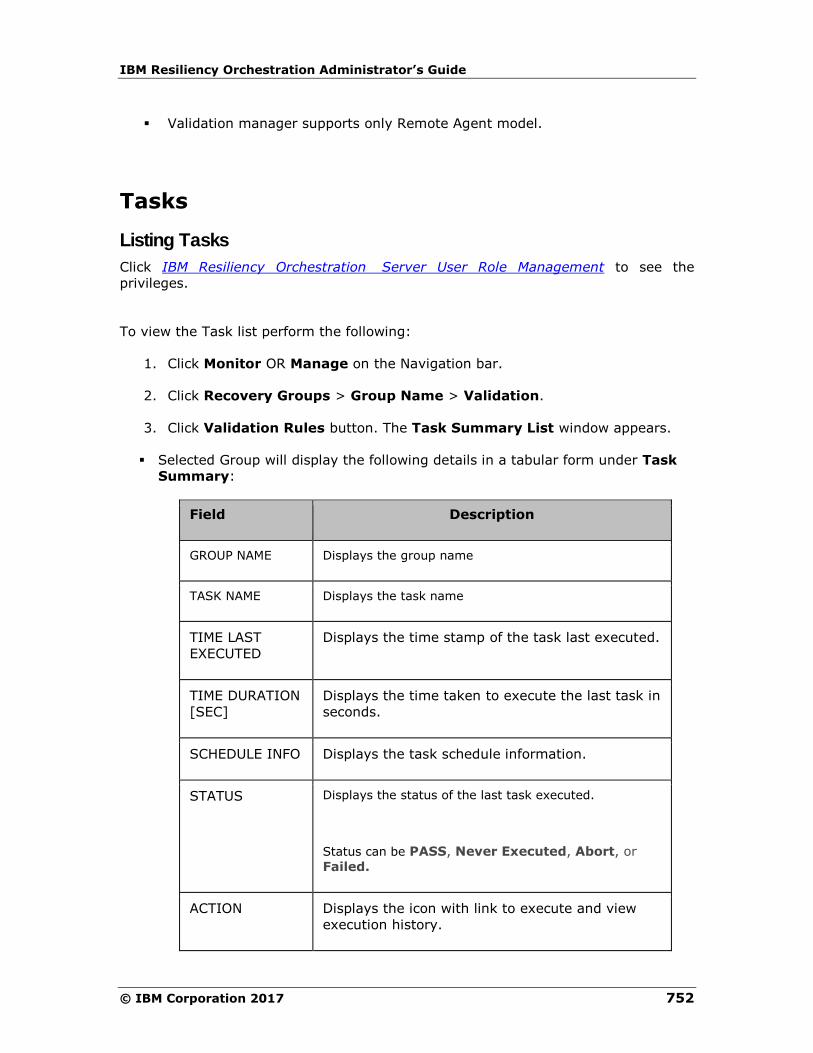
IBM Resiliency Orchestration Administrator’s Guide
© IBM Corporation 2017 752
▪ Validation manager supports only Remote Agent model.
Tasks
Listing Tasks
Click IBM Resiliency Orchestration Server User Role Management to see the
privileges.
To view the Task list perform the following:
1. Click Monitor OR Manage on the Navigation bar.
2. Click Recovery Groups > Group Name > Validation.
3. Click Validation Rules button. The Task Summary List window appears.
▪ Selected Group will display the following details in a tabular form under Task
Summary:
Field Description
GROUP NAME Displays the group name
TASK NAME Displays the task name
TIME LAST
EXECUTED
Displays the time stamp of the task last executed.
TIME DURATION
[SEC]
Displays the time taken to execute the last task in
seconds.
SCHEDULE INFO Displays the task schedule information.
STATUS Displays the status of the last task executed.
Status can be PASS, Never Executed, Abort, or
Failed.
ACTION Displays the icon with link to execute and view
execution history.
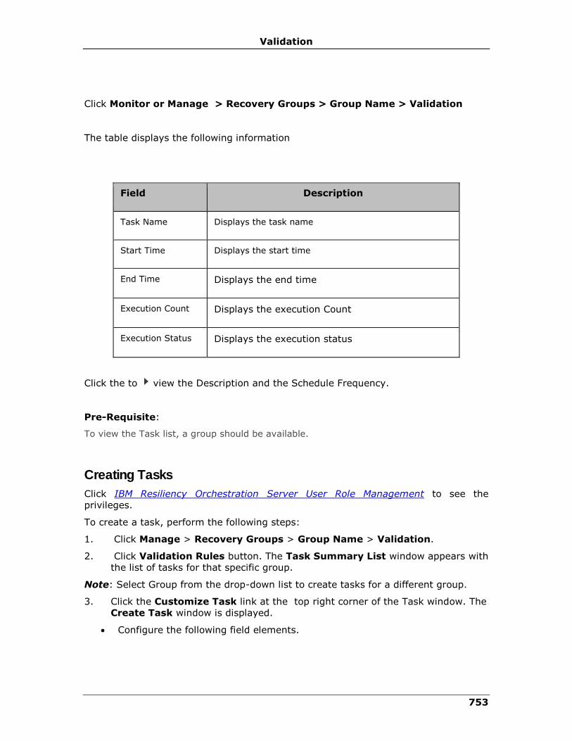
Validation
753
Click Monitor or Manage > Recovery Groups > Group Name > Validation
The table displays the following information
Field Description
Task Name Displays the task name
Start Time Displays the start time
End Time Displays the end time
Execution Count Displays the execution Count
Execution Status Displays the execution status
Click the to view the Description and the Schedule Frequency.
Pre-Requisite:
To view the Task list, a group should be available.
Creating Tasks
Click IBM Resiliency Orchestration Server User Role Management to see the
privileges.
To create a task, perform the following steps:
1. Click Manage > Recovery Groups > Group Name > Validation.
2. Click Validation Rules button. The Task Summary List window appears with
the list of tasks for that specific group.
Note: Select Group from the drop-down list to create tasks for a different group.
3. Click the Customize Task link at the top right corner of the Task window. The
Create Task window is displayed.
• Configure the following field elements.
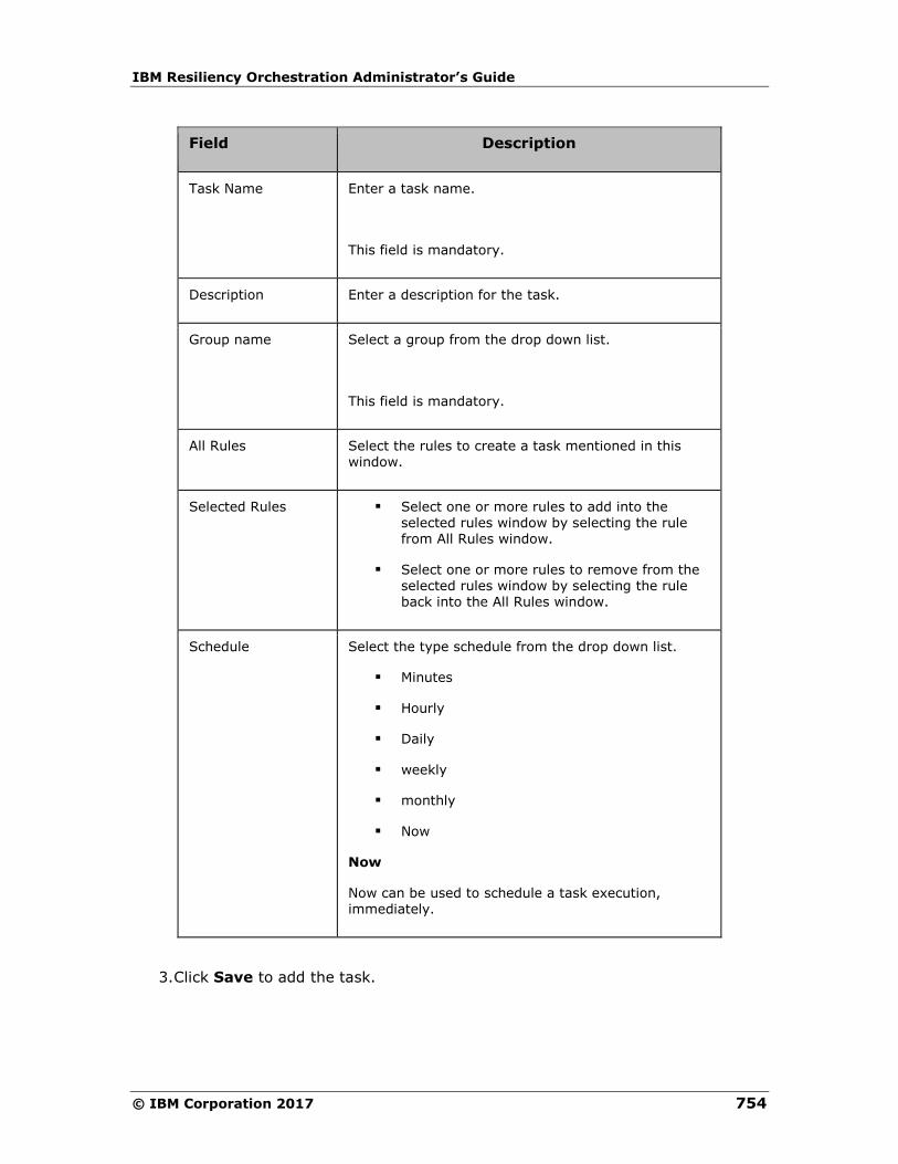
IBM Resiliency Orchestration Administrator’s Guide
© IBM Corporation 2017 754
Field Description
Task Name Enter a task name.
This field is mandatory.
Description Enter a description for the task.
Group name Select a group from the drop down list.
This field is mandatory.
All Rules Select the rules to create a task mentioned in this window.
Selected Rules ▪ Select one or more rules to add into the selected rules window by selecting the rule from All Rules window.
▪ Select one or more rules to remove from the selected rules window by selecting the rule back into the All Rules window.
Schedule Select the type schedule from the drop down list.
▪ Minutes
▪ Hourly
▪ Daily
▪ weekly
▪ monthly
▪ Now
Now
Now can be used to schedule a task execution, immediately.
3. Click Save to add the task.

Validation
755
Modifying Tasks
Click IBM Resiliency Orchestration Server User Role Management to see the
privileges.
To modify a Task, perform the following steps:
1. Click Manage > Recovery Groups > Group Name > Validation.
2. Click Validation Rules button. The Task Summary List window appears.
3. Click the Customize Task link at the top right corner. The Task List window
is displayed below the Create Task window.
4. Select a group from the Task List.
Each Group has the following fields:
• Task Name
• Description
• Rules
5. Click icon corresponding to the task that you want to modify. This opens
Modify Task page.
6. Make the required changes in the relevant field.
Note:
Task name cannot be modified.
7. Click Save to save the modifications.
Deleting Tasks
Click IBM Resiliency Orchestration Server User Role Management to see the
privileges.
To delete a Task, perform the following steps:
1. Click Manage > Recovery Groups > Group Name > Validation.
2. Click Validation Rules button. The Task Summary List window appears.
3. Click the Customize Task link at the top right corner. The Task List window
is displayed below the Create Task window.
4. Select a group from the Task List.
Each Group has the following fields:
• Task Name
• Description
• Rules
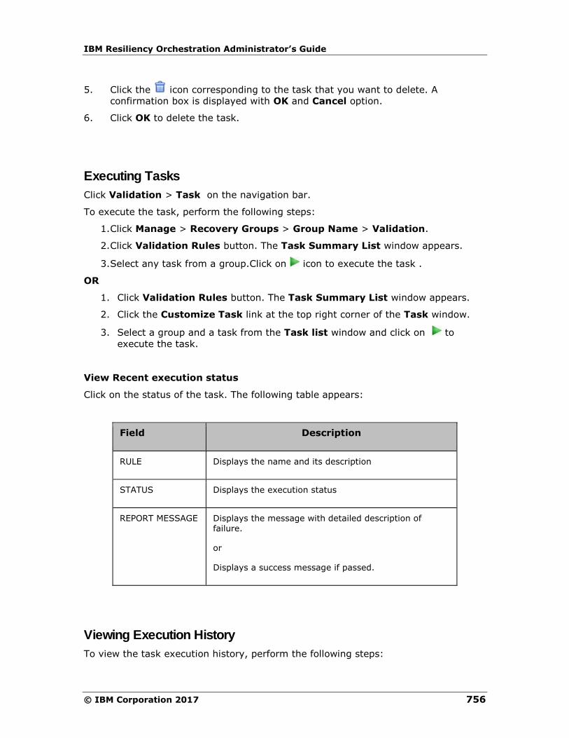
IBM Resiliency Orchestration Administrator’s Guide
© IBM Corporation 2017 756
5. Click the icon corresponding to the task that you want to delete. A
confirmation box is displayed with OK and Cancel option.
6. Click OK to delete the task.
Executing Tasks
Click Validation > Task on the navigation bar.
To execute the task, perform the following steps:
1. Click Manage > Recovery Groups > Group Name > Validation.
2. Click Validation Rules button. The Task Summary List window appears.
3. Select any task from a group.Click on icon to execute the task .
OR
1. Click Validation Rules button. The Task Summary List window appears.
2. Click the Customize Task link at the top right corner of the Task window.
3. Select a group and a task from the Task list window and click on to
execute the task.
View Recent execution status
Click on the status of the task. The following table appears:
Field Description
RULE Displays the name and its description
STATUS Displays the execution status
REPORT MESSAGE Displays the message with detailed description of failure.
or
Displays a success message if passed.
Viewing Execution History
To view the task execution history, perform the following steps:
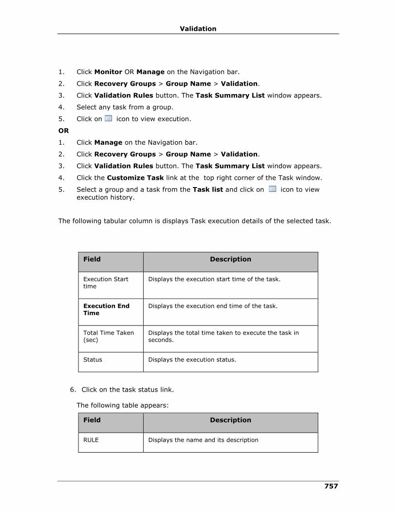
Validation
757
1. Click Monitor OR Manage on the Navigation bar.
2. Click Recovery Groups > Group Name > Validation.
3. Click Validation Rules button. The Task Summary List window appears.
4. Select any task from a group.
5. Click on icon to view execution.
OR
1. Click Manage on the Navigation bar.
2. Click Recovery Groups > Group Name > Validation.
3. Click Validation Rules button. The Task Summary List window appears.
4. Click the Customize Task link at the top right corner of the Task window.
5. Select a group and a task from the Task list and click on icon to view
execution history.
The following tabular column is displays Task execution details of the selected task.
Field Description
Execution Start time
Displays the execution start time of the task.
Execution End Time
Displays the execution end time of the task.
Total Time Taken (sec)
Displays the total time taken to execute the task in seconds.
Status Displays the execution status.
6. Click on the task status link.
The following table appears:
Field Description
RULE Displays the name and its description
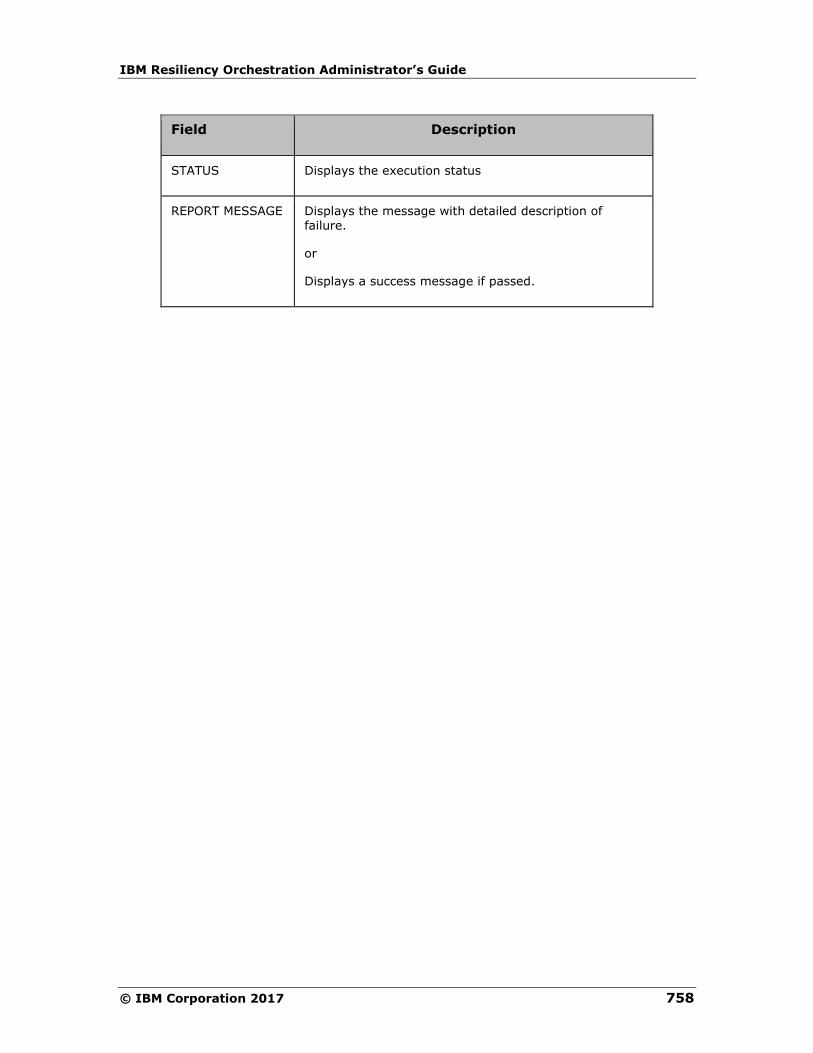
IBM Resiliency Orchestration Administrator’s Guide
© IBM Corporation 2017 758
Field Description
STATUS Displays the execution status
REPORT MESSAGE Displays the message with detailed description of failure.
or
Displays a success message if passed.
759
Reports
Reports Overview
You can generate reports on various continuity management and monitoring metrics
that includes RPO, RTO, and continuity operations for Groups under IBM Resiliency
Orchestration management.
You can generate the following reports:
▪ DR Drill/ Test Report - This report displays data for the drills carried out on
each Group.
▪ Events Report - This report displays the details of the events. The Events
Report option will be displayed only if the user has license for Recovery.
▪ RPO Report - This report fetches RPO details for the Group with the inputs
provided.
▪ RTO Report - This report displays the RTO details for the Group.
▪ Workflow Execution Report - This report displays the workflow execution
details.
▪ Data Lag Report - This report displays the amount of lag in data replication.
▪ WAN Report - This report provides a report on the WAN device during a
specified time period.
▪ Group Summary Report - This displays a summary of all the reports for the
selected group name for a fixed period of time.
▪ Test Summary Report - This displays a summary of the drills carried out for
the selected Group name for a fixed period of time.

IBM Resiliency Orchestration Administrator’s Guide
© IBM Corporation 2017 760
Note:
The Test Summary Report provides information about the recent status of all the
drills executed on a group. It provides two graphs - one displaying the execution
duration of each test instance, another displaying the success and failure status of
each test instance execution.
These graphs display multiple drills at a times. And within each drill, if it has multiple
instances of execution, those instances are also displayed. For example, if there are
two drills for the group, called drill 1 and drill 2, and if both were executed two
times, there will be four bars displayed in each graph, each bar representing one
instance of execution. Identification of the drill is done by the number (like 00.01
etc.) displayed in the horizontal-axis of the graph. This number corresponds to the
drill shown in the tabular listing, shown immediately above the graph.
You can navigate to reports by clicking REPORTS on the navigation bar. The
Reports page appears with the following information:
Reports Across All Groups
Select Report Displays drop-down list to select the report to be generated.
Date Range Displays From and To fields to select the period for which the reports are to be generated.
These fields are not displayed if you select Test Summary Report and Group Summary Report.
Include System Workflows
Displays the checkbox to select whether to include or exclude system workflows.
This is displayed only if you select Workflow
Execution report.
Reports per Group
GROUP NAME Displays Group names
DATA AVAILABLE SINCE
Displays the date with the time stamp from when the report data is available for the respective Group.
Click of GROUP NAME column to sort by Group states.

Reports
761
Note:
The report data is available for the Group that is under IBM Resiliency Orchestration
management.
Reports are available only at Recovery Group level. It is not applicable for Application
Group.
Viewing Reports Viewing DR Drill/Test Report
The following steps will display the consolidated DR Drill report for all Groups:
1 Click REPORTS on the navigation bar. The Reports page appears.
2 Select DR Drill/ Test Report from the Select Report drop-down list.
3 Select the period by clicking dates from the corresponding icon for From and To
fields.
4 Click View. The DR Drill Report page appears. This page displays the
consolidated summary for each of the drills with their GROUP NAME, DRILL NAME,
START TIME, END TIME, DURATION (HRS) and STATUS.
5 Click any DRILL NAME link. The Workflow Status Details page appears. This page
displays detailed report with the list of actions and their details.
Viewing BCP Test Report
The following steps will display the consolidated BCP Test Report for all Groups:
1 Click REPORTS on the navigation bar. The Reports page appears.
2 Select BCP Test Report from the Select Report drop-down list.
3 Select the period by clicking dates from the corresponding icon for From and To
fields.
4 Select the required Groups from the Select Groups list.
Click View. The BCP Test Report appears. This page displays the consolidated
summary for each of the drills with their Executive Summary, Introduction, DR Setup
and scope of Drill, DR Drill Details and Conclusion.
The Report also provides options like Print Report, Back to View Reports and Export
to PDF and RTF formats.
Note
The report will be enabled only if the Banking Module is licensed.
Viewing BCP Readiness Report
The following steps will display the consolidated BCP Readiness Report for all Groups:
1 Click REPORTS on the navigation bar. The Reports page appears.
2 Select BCP Readiness Report from the Select Report drop-down list.
IBM Resiliency Orchestration Administrator’s Guide
© IBM Corporation 2017 762
3 Select the required Groups from the Select Groups list.
4 Click View. The BCP Readiness Report page appears. This page displays the
consolidated summary for each of the tests with their Executive Summary, DR Setup
Description, and Application DR Readiness Detail.
The Report also provides options like Print Report, Back to View Reports and Export
to PDF and RTF formats.
Note
The report will be enabled only if the Banking Module is licensed.
Viewing Major Failure Report
The following steps will display the consolidated Major Failure Report for all Groups:
1 Click REPORTS on the navigation bar. The Reports page appears.
2 Select Major Failure Report from the Select Report drop-down list.
3 Select the period by clicking dates from the corresponding icon for From and To
fields.
4 Select the required Groups from the Select Groups list.
5 Click View. The Major Failure Report page appears. This page displays the
consolidated summary for each of the tests with their Executive Summary, DR Setup
Description, and Failure Details by Application.
The Report also provides options like Print Report, Back to View Reports and Export
to PDF and RTF formats.
Note
The report will be enabled only if the Banking Module is licensed.
Viewing BCP Integrity Check Report
The following steps will display the consolidated BCP Integrity Check Report for all
Groups:
1 Click REPORTS on the navigation bar. The Reports page appears.
2 Select BCP Integrity Check Report from the Select Report drop-down list.
3 Select the period by clicking dates from the corresponding icon for From and To
fields.
4 Select the required Groups from the Select Groups list.
5 Click View. The BCP Integrity Check Report page appears. This page displays the
consolidated summary for each of the drills with their Summary and Application DR
Integrity Detail.
The Report also provides options like Print Report, Back to View Reports and Export
to PDF and RTF formats.
Reports
763
Integrity Check is a default drill which is applicable for all the DR solutions. When a
Recovery group is created, by default Integrity Check drill will be displayed on GUI in
the below two places.
▪ Discover > Groups > Select the Recovery Group > Group Configuration
> Drills
Integrity Check drill cannot be deleted and this comes with “custom” action
configuration.
Note:
The report will be enabled only if the Banking Module is licensed.
Viewing Events Report
1 Click REPORTS on the navigation bar. The Reports page appears
2 Under Report Across All Groups section, select Event Report from the drop
down list box and select the From Date and To Date.
• Select Event type (atleast one or all).
• Select Event severity (atleast one or all).
• Select Event status (atleast one or all).
• Select Group from the list box (atleast one or all)
3 Click on view button and the Events Report will appear.
Viewing Snapshot manager Report
Users can view reports through email as in-line text without logging into IBM
Resiliency Orchestration product. The two reports are as follows:
1. Summary Report
2. Detail Report
Four options have been configured for Executive Reports. They are as follows:
1 View Report
a. Summary Report: This link enables the logged-in user to view
Summary Reports contents before sending emails. The link will be
enabled only if managed groups are available.
b. Detail Report: This link enables the logged-in user to view Detail
Reports contents before sending emails. The link will be enabled only if
managed groups are available.
2. Configure Schedule
Both the summary report and detailed report can be configured in the same way. On
clicking the Configure schedule link, a pop window will appear and the user can
schedule the frequency of emails.
3 Edit email-recipients:

IBM Resiliency Orchestration Administrator’s Guide
© IBM Corporation 2017 764
On clicking the Edit email Recipients link, a pop window will appear and the user can
add/ delete email–ids of the email recipients of summary and detail reports.
Note
Clicking the Add/ Delete buttons will not update the email-ids in the database table.
Click the save button to update the database table. Multiple email-ids (separated by
commas) can be added at a time.
i.Send Email Report
ii.An email can be sent only if the following fields are configured under
the Configure Notifications Email Server section.
iii.SMTP Server Name
iv.Sender E-mail address
v.Reply To
vi.Password
vii.Send Email Report Now : This option sends email to the configured
recipients immediately. The option may be disabled if
viii.no managed groups are available
ix.there are no email recipients configured.
x.Send Email Report at Configured interval : The reports will be mailed
to the configured recipients automatically based on the configured
interval.
Viewing reports for a group
1 Click REPORTS on the navigation bar. The Reports page appears.
2 Click a Group from the GROUP NAME column. The Reports page with <group
name> appears. This page provides graphical representation of all the reports for the
specified Group.
Note:
1. You can navigate to Monitor, Manage, Drills or Discover page of a
displayed group by clicking on the respective icon at the top right
corner of the page.
2. Click the thumb-nail representation of the respective graph to
maximize the graph. Click Print Graph and select the printer to print
the graph.
Viewing Workflow Execution Report
This report consolidates the execution of Workflows related to BCOs, Drills, RPO, and
Business Processes.
1 Click REPORTS on the navigation bar. The Reports page appears.
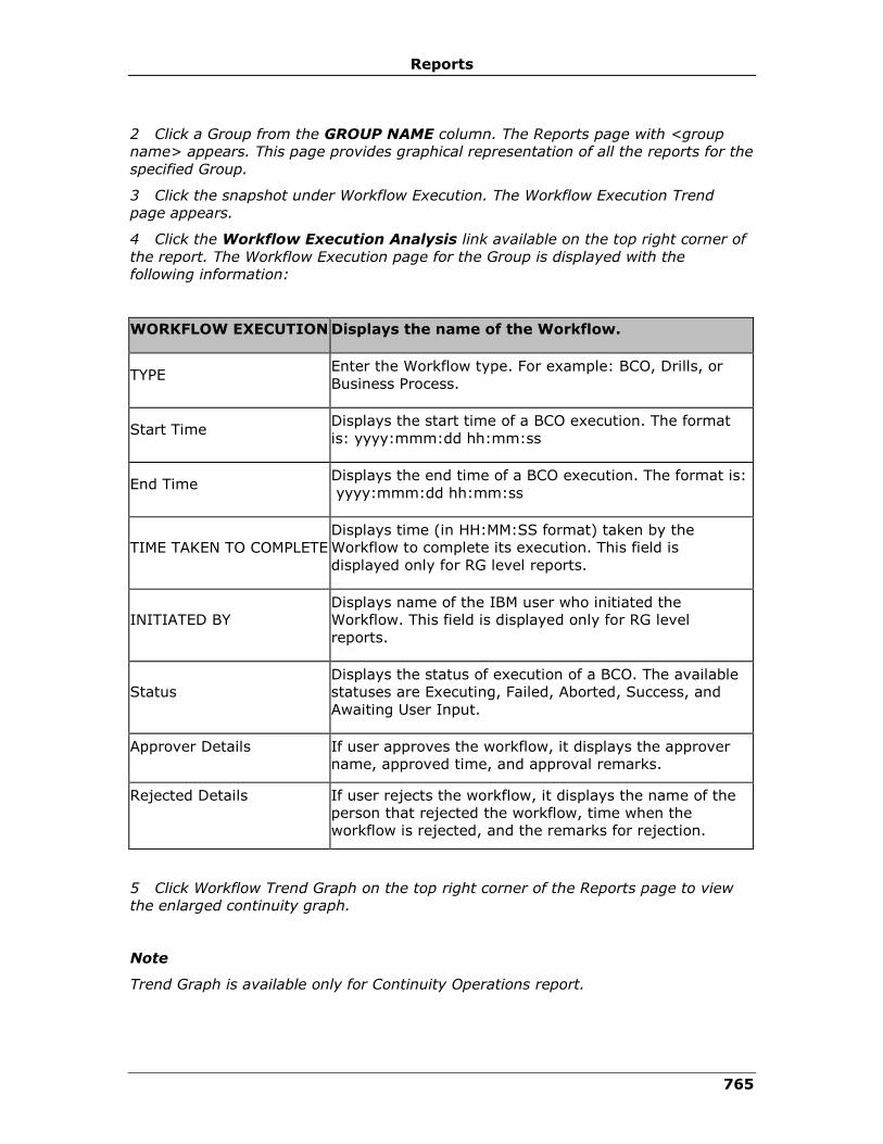
Reports
765
2 Click a Group from the GROUP NAME column. The Reports page with <group
name> appears. This page provides graphical representation of all the reports for the
specified Group.
3 Click the snapshot under Workflow Execution. The Workflow Execution Trend
page appears.
4 Click the Workflow Execution Analysis link available on the top right corner of
the report. The Workflow Execution page for the Group is displayed with the
following information:
WORKFLOW EXECUTION Displays the name of the Workflow.
TYPE Enter the Workflow type. For example: BCO, Drills, or
Business Process.
Start Time Displays the start time of a BCO execution. The format
is: yyyy:mmm:dd hh:mm:ss
End Time Displays the end time of a BCO execution. The format is:
yyyy:mmm:dd hh:mm:ss
TIME TAKEN TO COMPLETE
Displays time (in HH:MM:SS format) taken by the
Workflow to complete its execution. This field is
displayed only for RG level reports.
INITIATED BY
Displays name of the IBM user who initiated the
Workflow. This field is displayed only for RG level
reports.
Status
Displays the status of execution of a BCO. The available
statuses are Executing, Failed, Aborted, Success, and
Awaiting User Input.
Approver Details If user approves the workflow, it displays the approver
name, approved time, and approval remarks.
Rejected Details If user rejects the workflow, it displays the name of the
person that rejected the workflow, time when the
workflow is rejected, and the remarks for rejection.
5 Click Workflow Trend Graph on the top right corner of the Reports page to view
the enlarged continuity graph.
Note
Trend Graph is available only for Continuity Operations report.
IBM Resiliency Orchestration Administrator’s Guide
© IBM Corporation 2017 766
Viewing Workflow Execution History
You can view the Workflow execution history by clicking its name in the Workflow
Execution Report page of a Group. To view this history, perform the following steps:
1 Click REPORTS on the navigation bar. The Reports page appears.
2 Click a Group from the GROUP NAME column. The Reports page with <group
name> appears. This page provides graphical representation of all the reports for the
specified Group.
3 Click the snapshot under Workflow Execution. The Workflow Execution Trend
page appears.
4 Click the Workflow Execution Analysis link available on the top right corner of
the report. The Workflow Execution page appears.
5 Click desired Workflow name in the Workflow Execution column to open the
Workflow Status Details page displaying the history.
Viewing Dry Run Report
The following steps will display the Dry Run report for all Groups:
1 Click REPORTS on the navigation bar. The Reports page appears.
2 Click a Group from the Reports Per Group. The Reports page with <group name>
appears. This page provides graphical representation of all the reports for the
specified Group.
3 From the Select Report drop-down list, select the Dry Run Execution.
4 Select the Date Range to list the dry runs executed during the time period.
Viewing Replication Report
This helps you to fetch a report on replications that have taken place so far.
1 Click Replication Reports link on the Reports for the Group window. The
Replication Reports for the Group window is displayed.
2 Select Duration from drop-down list box on the Replication Reports window.
3 Click Fetch button to retrieve the report.
4 Click Back to go back to the previous window.
Based on the time period you select, the Replication report for that group is
generated.
You can see the report generated with the following details on replication details for
the specified time period:
▪ RG Name – Displays the name of the Recovery group.
▪ Time of replication - Displays the time stamp of the replication.
▪ Size replicated – Displays the size of the replicated file.
▪ File included in the replicated- Displays the name of the file replicated.
Viewing RPO Report
Recovery Point Object report fetches RPO details with the input provided. To
generate report on RPO, perform the following steps:

Reports
767
1 Click RPO Reports link on the Reports for the Group window. The ‘RPO Reports
for the Group’ window is displayed.
2 Enter the options for RPO report generation.
3 Enter RPO Deviation Threshold in percentage.
4 Select Duration from the list box.
5 Click Fetch button to retrieve the report or click Back button to go back to the
previous window.
This fetches you RPO greater than the value entered in the ‘Deviation Threshold’ and
occurred during the time period specified in the ‘Duration’ field.
For example: The value specified in the ‘Deviation threshold’ is 30% and the
duration given is one week, then, on clicking the fetch button will throw RPO greater
than 30% that occurred one week back from the current time at which this query is
submitted to the database.
If the value provided is out of range or data is not available with in the range
specified, then a message box is displayed, informing report generation failure.
6 Click OK button on the message box to close it and enter new values for RPO
deviation threshold and duration.
Viewing WAN Report
The WAN Link Report provides a report on the WAN device during a specified time
period.
1 Select Duration from drop-down list box for which you want to fetch the report.
Based on the time period you select, the WAN link report for that Group and the
WAN device is generated.
2 Select the device name from the drop-down list and click GO button. The list
box contains all WAN devices belonging to that Group. Select a particular WAN
device to display the report on its associated ports with the “Port Name”, “Usable
Bandwidth”. and “Operation Status”.
To generate printable view of the reports, perform the following:
1. Click Printable View button on the respective reports generation window. This
button is displayed on the right top corner of the window. On clicking the
Printable view button opens a window displaying the generated report in a
printable form.
2. Click Print button to print the report.
3. Click Close Window to close the window.
Viewing Events Report
The following steps will display the consolidated Events report for all Groups:
1 Click REPORTS on the navigation bar. The Reports page appears.
2 Select Events Report from the Select Report drop-down list.

IBM Resiliency Orchestration Administrator’s Guide
© IBM Corporation 2017 768
Field Description
Date/Time Range
From Click and select the date/ time from which
the event started.
To Click and select the date/ time till which the
event occurred.
Select Event Type
Group Events Select this check box to generate report of the
group events.
All User Input
Events
Select this check box to generate report of all
user input events.
System Events Select this check box to generate report of the
system events.
Select Event Severity
Critical Select this check box to generate report of the
critical events.
Serious Select this check box to generate report of the
serious events.
Warning Select this check box to generate report of the
warning events.
Information Select this check box to generate report of the
information events.
Select Event Status
New Select this check box to generate report of new
events.
In Progress Select this check box to generate report of the
events whose status is In progress.
Closed Select this check box to generate report of the
events that are closed.

Reports
769
Field Description
Select Groups Select the required group from the list. The
report will have details of events associated
with the selected groups.
Hold down the "Ctrl" key to select more than
one group.
Viewing Dry Run Report
The following steps will display the Dry Run report for all Groups:
1 Click REPORTS on the navigation bar. The Reports page appears.
2 Click a Group from the Reports Per Group. The Reports page with <group
name> appears. This page provides graphical representation of all the reports for
the specified Group.
3 From the Select Report drop-down list, select Dry Run Execution.
4 Select the Date Range to list the dry runs executed during the time period.
Field Description
From Click and select the start date.
To Click and select the end date.
Click the View Details button. The following details are displayed in tabular
form, as shown in the following table.
Field Description
Dry Run Execution Displays the name of the dry run execution.
Start Time Displays the start time and date of the dry run.
End Time Displays the end time and date of the dry run.
Initiated By Displays the user role that executed the dry
run.
Errors/Warnings Displays the number of errors and warnings
numerically in the format Errors/Warnings.
IBM Resiliency Orchestration Administrator’s Guide
© IBM Corporation 2017 770
5 Click on the name of the dry run below the Dry Run Execution column. The
window displays Dry Run Execution status.
6 The Dry Run Execution status displays the dry run report in Summary and
Detailed.
Summary Report
The Summary Report section displays the following:
▪ The name of the dry run execution.
▪ The user role that started the dry run.
▪ The number of errors and warnings.
▪ The start time of the dry run execution.
▪ The end time of the dry run execution.
Note
Click Export to CSV link to save the summary in a CSV file.
Detailed Report
The Detailed Report section displays the following:
▪ The name of each RAL.
▪ Image indicating success, fail or custom.
▪ Image representing the type of action.
▪ Execution environment:
1. Component IP
2. Component Name
3. Database Name
▪ All Key Value pairs for the given RAL.
▪ Errors and warnings are displayed with an image indicator and a descriptive
message.
▪ The actual RAL command.
Note
Click Hide Details link to hide the details for each RAL.
Point to the image representation of Type to view the type of workflow.
For actions that do not support the Dry Run feature, only framework level
information is logged.
Viewing Validation Report
The following steps will display the consolidated Validation report for all Groups:

Reports
771
1 Click REPORTS on the navigation bar. The Reports page appears.
2 Click any group from the group list from the page.
3 Select Validation Manager from the Select Report drop-down list.
Field Description
Date/ Time Range
From Click and select the date/time from which the event started.
To Click and select the date/time till which the event occurred.
The Validation Report provides a report during a specified time period.
1. Select Duration from drop-down list box for which you want to fetch
the report.
2. Based on the time period.
3. Select View Graph.
To generate printable view of the reports, perform the following:
▪ Click Printable View button on the on the right top corner of the respective
reports generation window.
▪ Click Print button to print the report.
▪ Click Close Window to close the window.
To view the Tabular view: Select Tabular View Button, this displays the list of task
executions in the below tabular form:
Task Name Displays the task name
Execution Start time Displays the execution start time.
Execution End time
Displays the execution end time.
Pass Rules Displays the number rules passed in the task execution.
Fail Rules Displays the number rules failed in the task execution.
Pass Rule % Displays the passed rule percentage.
IBM Resiliency Orchestration Administrator’s Guide
© IBM Corporation 2017 772
Note:
Application Group will have the following reports:
RTO
▪ Workflow execution
▪ Group summary report
▪ Test summary report
▪ Dryrun execution report
Printing Reports
After generating the selected report, the user can print the report, by performing the
following steps:
1. Click REPORTS on the navigation bar. The Reports page appears.
2. Click the appropriate group name. The report for the selected group name
appears.
3. In Select Report, select the appropriate report to print.
4. In Date Range, specify the period by selecting the dates in From and To
icons.
5. Click View graph. The snapshot of the report to be printed is displayed.
6. Click Print Graph to print the report.
To enable the print background option, perform any one of the following based on
the browser you are using:
Internet Explorer:
▪ Click Tools > Internet Options > Advanced. Under Printing category, select
the Print background colors and images check box.
Firefox:
1. Click File > Page setup > Format and Option. Select the Print background
(colors & images) check box.
2. Click Print Graph or Print Report, whichever displays at the bottom of the
report.
3. The Print dialog box appears. Click Print.
Note:
Reports
773
The lines in the graph will be visible in the print if the "print background colors and
images" option is enabled in the browser. This is a browser setting error and cannot
be handled by IBM Resiliency Orchestration software.
Exporting a Report
You can export a report after generating it as a Portable Document Format (PDF) or
as an HTML page.
Complete the following steps to export a report:
1. Click Reports on the navigation bar. The Reports page appears.
2. Select the group for which you want the report.
3. In the Select Report dropdown, select the report type.
Note:
The following reports can be exported as a PDF or HTML page:
• RPO
• Data RPO
• RTO
• Data Lag
• Test Summary Report
4. Click Customize Report Duration.
5. Specify the duration by selecting the dates in the Date Range fields by
selecting the dates from the From and To icons.
6. Click View Graph. The snapshot of the report displays in a graphical view.
7. Click Tabular View to view the report details in a tabular format.
8. You can save the report details by exporting the report as a PDF or an HTML
page by completing the following steps:
• Click Export to PDF to export the report as a PDF
• Click Export to HTML to export the report as a HTML page
The PDF or HTML displays in a separate window, and you can save the displayed
PDF or HTML to a location on your local drive from the menu options on the
screen.
Customizing Reports
You can customize the report to display specific report data for a given period by
performing the following steps:
1. Click REPORTS on the navigation bar. The Reports page appears.

IBM Resiliency Orchestration Administrator’s Guide
© IBM Corporation 2017 774
2. Click desired Group in the GROUP NAME column. The Reports page with
<group name> appears.
3. Select the type of report to be customized from the Select Report drop-down
list. You can customize the following reports for the respective group:
▪ RTO Report
▪ Workflow Execution Report
▪ DryRun Execution Report
▪ Group Summary Report
4. Select the period by clicking dates from the corresponding icon for From
and To fields.
When Workflow Execution is selected, the Include System Workflows
checkbox is displayed.
5. Select the checkbox to display the system workflows also. For more information
regarding system workflows, refer Working with Workflow Manager.
Note:
Users with operator's privilege can generate reports.
Group Summary Report
This report displays the following information for the selected group name for last
seven days from today.
Field Description
Group Name Displays the selected group name.
Admin User Displays the name of the users who have the
permission to perform Admin activities.
Current State Displays the current state of the group.
DR Solution Signature Displays the workflow action for the DR Solution Signature.
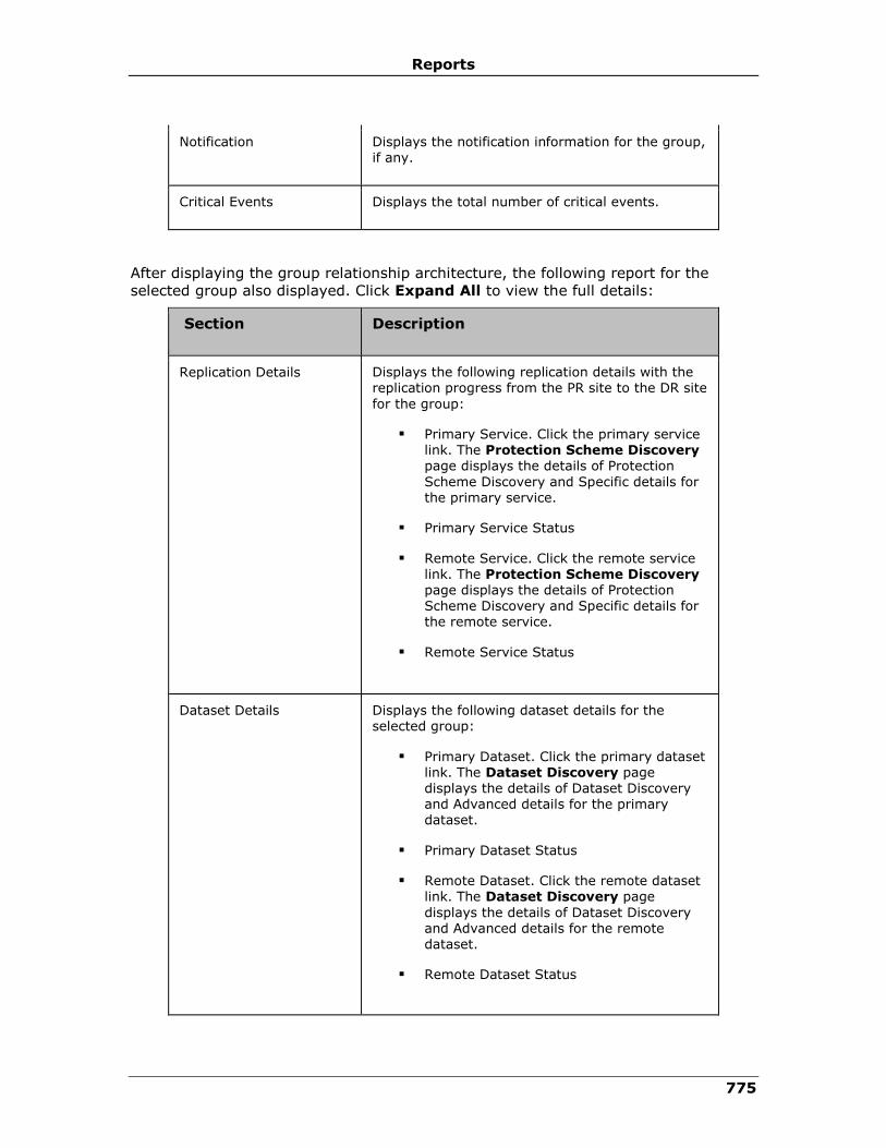
Reports
775
Notification Displays the notification information for the group, if any.
Critical Events Displays the total number of critical events.
After displaying the group relationship architecture, the following report for the
selected group also displayed. Click Expand All to view the full details:
Section Description
Replication Details Displays the following replication details with the replication progress from the PR site to the DR site
for the group:
▪ Primary Service. Click the primary service link. The Protection Scheme Discovery page displays the details of Protection
Scheme Discovery and Specific details for the primary service.
▪ Primary Service Status
▪ Remote Service. Click the remote service link. The Protection Scheme Discovery page displays the details of Protection
Scheme Discovery and Specific details for the remote service.
▪ Remote Service Status
Dataset Details Displays the following dataset details for the selected group:
▪ Primary Dataset. Click the primary dataset link. The Dataset Discovery page displays the details of Dataset Discovery and Advanced details for the primary dataset.
▪ Primary Dataset Status
▪ Remote Dataset. Click the remote dataset link. The Dataset Discovery page
displays the details of Dataset Discovery and Advanced details for the remote dataset.
▪ Remote Dataset Status
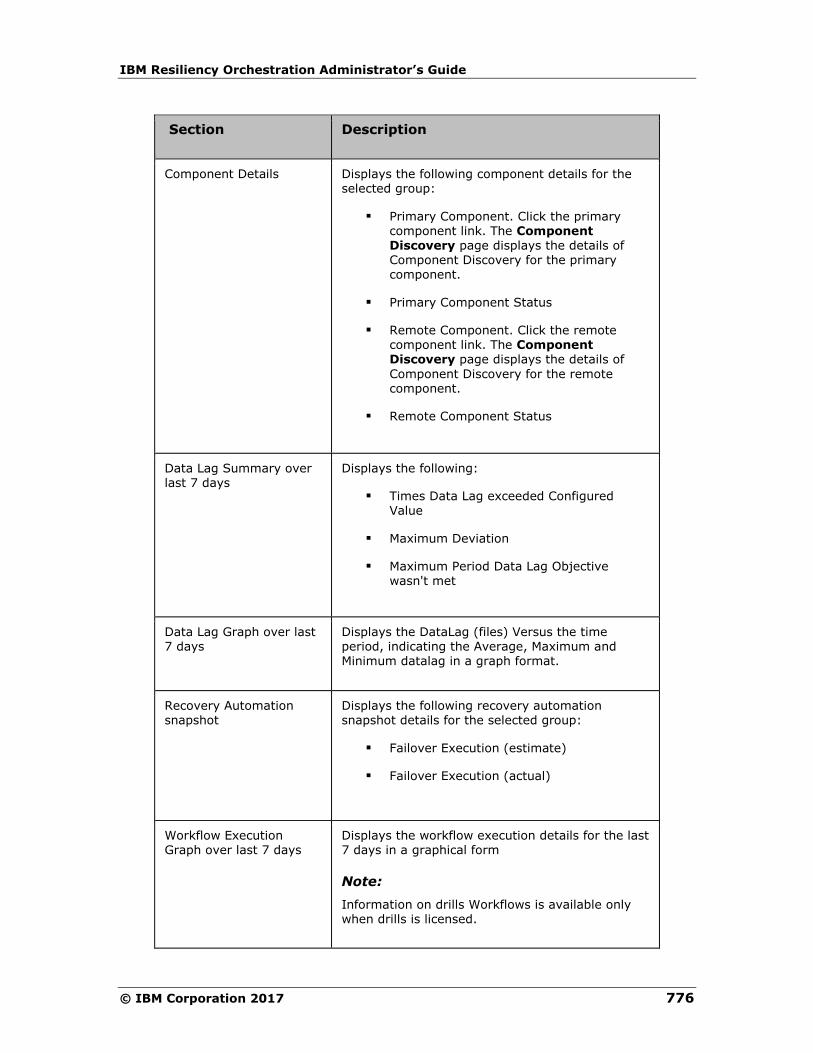
IBM Resiliency Orchestration Administrator’s Guide
© IBM Corporation 2017 776
Section Description
Component Details Displays the following component details for the selected group:
▪ Primary Component. Click the primary component link. The Component Discovery page displays the details of Component Discovery for the primary component.
▪ Primary Component Status
▪ Remote Component. Click the remote component link. The Component Discovery page displays the details of
Component Discovery for the remote component.
▪ Remote Component Status
Data Lag Summary over last 7 days
Displays the following:
▪ Times Data Lag exceeded Configured Value
▪ Maximum Deviation
▪ Maximum Period Data Lag Objective wasn't met
Data Lag Graph over last 7 days
Displays the DataLag (files) Versus the time period, indicating the Average, Maximum and Minimum datalag in a graph format.
Recovery Automation snapshot
Displays the following recovery automation snapshot details for the selected group:
▪ Failover Execution (estimate)
▪ Failover Execution (actual)
Workflow Execution Graph over last 7 days
Displays the workflow execution details for the last 7 days in a graphical form
Note:
Information on drills Workflows is available only when drills is licensed.

Reports
777
Section Description
Drills Details Displays the summary of drills details for the last 7 days that executed by the selected Group:
▪ Group Name
▪ Drill Name
▪ Start Time
▪ End Time
▪ Duration (Hrs)
▪ Status
RTO Graph over last 7 days
Displays the RTO details for the last 7 days of the selected group in the graphical form.
WAN Graph over last 7 days
Displays the WAN utilisation by the selected group for the last 7 days in a graphical form.
Test Summary Report
The Test Summary Report provides information about the recent status of all the
Drills executed on a Group. It displays the data for the last three years. This option
is available only in Tests License.
To generate Test Summary Report:
1. Click Reports on the navigation bar. The Reports page appears.
2. Select the group for which you want to generate the test summary report from
the Reports Per Group section.
3. Select Tests Summary Report from the Select Report drop-down list and
click View Graph. The Test Summary Report page appears.
Field Description
Group Name Displays the group name.
DR Solution Signature
Displays the DR solution signature.
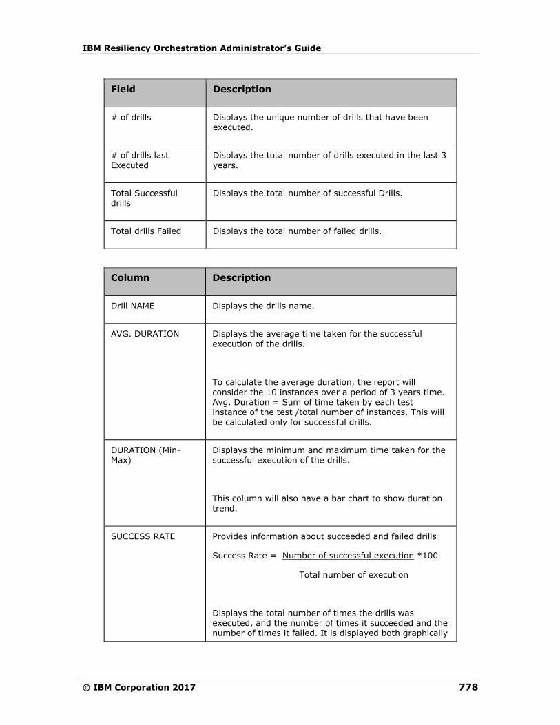
IBM Resiliency Orchestration Administrator’s Guide
© IBM Corporation 2017 778
Field Description
# of drills Displays the unique number of drills that have been executed.
# of drills last Executed
Displays the total number of drills executed in the last 3 years.
Total Successful drills
Displays the total number of successful Drills.
Total drills Failed Displays the total number of failed drills.
Column Description
Drill NAME Displays the drills name.
AVG. DURATION Displays the average time taken for the successful execution of the drills.
To calculate the average duration, the report will consider the 10 instances over a period of 3 years time. Avg. Duration = Sum of time taken by each test instance of the test /total number of instances. This will be calculated only for successful drills.
DURATION (Min-Max)
Displays the minimum and maximum time taken for the successful execution of the drills.
This column will also have a bar chart to show duration trend.
SUCCESS RATE Provides information about succeeded and failed drills
Success Rate = Number of successful execution *100
Total number of execution
Displays the total number of times the drills was executed, and the number of times it succeeded and the number of times it failed. It is displayed both graphically

Reports
779
Column Description
and textually.
In the graphical representation, the green line represents the successful execution and the red line represents the failed execution.
In the textual representation, the text in green is the number of times the drills succeeded, the text in red is
the number of times the drills failed and the text in black is the total number of times the drills got executed.
Note:
Click the Print Report button to print the test summary report.
4. Click the test name link to view the execution details of the recent instances.
Field Description
START TIME Displays the start time of the drills execution.
END TIME Displays the end time of the drills execution.
DURATION(HRS) Displays the duration of the drills execution.
STATUS Displays the status of the drills execution.
The following charts are also displayed:
• "Execution duration" chart
Each of the bars shown in the graph will have a duration as tooltip.
• "Success Rate" Pie-chart
A green Pie representing the successful tests and red Pie representing the failed tests
will be displayed. Each of the Pies will have the succeeded/ failed tests' count as
labels.
5. Click the Details link corresponding to the test instance. The Execution
Status page appears.

IBM Resiliency Orchestration Administrator’s Guide
© IBM Corporation 2017 780
Field Description
Name Displays the name and status (in brackets) of the drill.
Group Displays the group to which the workflow belongs.
Start Time Displays the time at which the drills execution is initiated. The time taken for the execution is also displayed in brackets.
End Time
Displays the time at which the drills execution is completed.
View Details Click this link to view the Key value pair for this workflow.
Export to CSV Click this link to export the report to excel sheet.
Workflow Actions
Name Displays the name of the workflow action.
Status Displays the status of the workflow action.
Time Initiated Displays the time at which the action started.
Time Elapsed (Sec) Displays the time taken to complete the workflow action.
Type Displays the action type as a symbol.
Details Click the View Details link to view the execution log details.
Custom Report Framework
Using the Custom Reports framework, customer can develop customized reports
based on the data monitored and captured by IBM Resiliency Orchestration server.
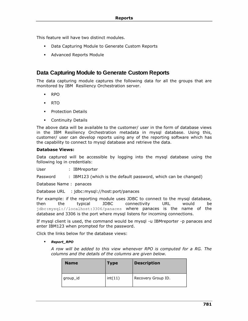
Reports
781
This feature will have two distinct modules.
▪ Data Capturing Module to Generate Custom Reports
▪ Advanced Reports Module
Data Capturing Module to Generate Custom Reports
The data capturing module captures the following data for all the groups that are
monitored by IBM Resiliency Orchestration server.
▪ RPO
▪ RTO
▪ Protection Details
▪ Continuity Details
The above data will be available to the customer/ user in the form of database views
in the IBM Resiliency Orchestration metadata in mysql database. Using this,
customer/ user can develop reports using any of the reporting software which has
the capability to connect to mysql database and retrieve the data.
Database Views:
Data captured will be accessible by logging into the mysql database using the
following log in credentials:
User : IBMreporter
Password : IBM123 (which is the default password, which can be changed)
Database Name : panaces
Database URL : jdbc:mysql://host:port/panaces
For example: if the reporting module uses JDBC to connect to the mysql database,
then the typical JDBC connectivity URL would be
jdbc:mysql://localhost:3306/panaces where panaces is the name of the
database and 3306 is the port where mysql listens for incoming connections.
If mysql client is used, the command would be mysql -u IBMreporter -p panaces and
enter IBM123 when prompted for the password.
Click the links below for the database views:
▪ Report_RPO
A row will be added to this view whenever RPO is computed for a RG. The
columns and the details of the columns are given below.
Name Type Description
group_id int(11) Recovery Group ID.

IBM Resiliency Orchestration Administrator’s Guide
© IBM Corporation 2017 782
Name Type Description
group_name varchar(32) Recovery Group Name.
rpo_value int(11) RPO value in seconds.
rpo_deviation int(11) RPO deviation from the configured value in percentage.
time datetime Time when RPO was computed.
pri_last_txn_id varchar(255) Last transaction ID on the primary.
pri_last_txn_time varchar(255) Last transaction ID time on the primary.
dr_last_txn_id varchar(255) Last transaction ID on the DR.
dr_last_txn_time varchar(255) Last transaction ID time on the DR.
▪ Report_RTO
A row will be added to this view for each action in the Failover workflow
whenever RTO is computed for a Recovery group. The columns and the
details of the columns are given below.
Name Type Description
id int(11) ID to identify the rows of the RTO computation
instance.
group_id int(11) Recovery Group ID.
group_name varchar(32) Recovery Group Name.
rto_value int(11) RTO value in seconds.
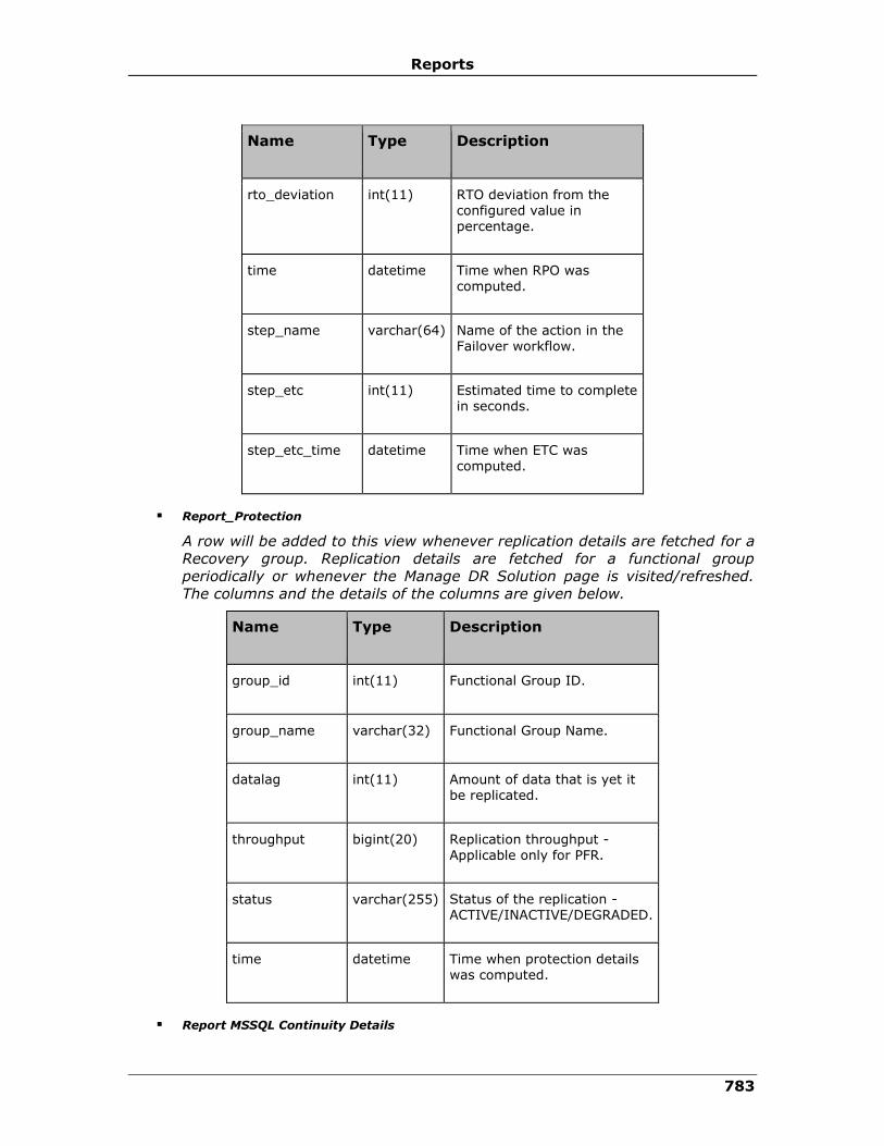
Reports
783
Name Type Description
rto_deviation int(11) RTO deviation from the configured value in percentage.
time datetime Time when RPO was computed.
step_name varchar(64) Name of the action in the Failover workflow.
step_etc int(11) Estimated time to complete in seconds.
step_etc_time datetime Time when ETC was computed.
▪ Report_Protection
A row will be added to this view whenever replication details are fetched for a
Recovery group. Replication details are fetched for a functional group
periodically or whenever the Manage DR Solution page is visited/refreshed.
The columns and the details of the columns are given below.
Name Type Description
group_id int(11) Functional Group ID.
group_name varchar(32) Functional Group Name.
datalag int(11) Amount of data that is yet it be replicated.
throughput bigint(20) Replication throughput -
Applicable only for PFR.
status varchar(255) Status of the replication - ACTIVE/INACTIVE/DEGRADED.
time datetime Time when protection details was computed.
▪ Report MSSQL Continuity Details

IBM Resiliency Orchestration Administrator’s Guide
© IBM Corporation 2017 784
A row will be added to the view whenever the continuity details are fetched
and is different from the previously fetched values for any of the MSSQL
Recovery groups. The columns and the details of the columns are given
below.
Name Type Description
group_id int(11) Recovery Group ID.
group_name varchar(32) Recovery Group Name.
computed_time datetime Time when continuity details was gathered.
pri_last_backedup_translog varchar(255) Name of the last transaction log that was backed up on primary.
pri_last_backedup_translog_time datetime Time when last transaction log was backed up on primary.
dr_last_restored_translog varchar(255) Name of the last transaction log that was
restored up on DR.
pri_last_backedup_translog_time datetime Time of the last transaction log that was restored up on DR.
▪ Report_Oracle_Continuity_Details
A row will be added to the view whenever the continuity details are fetched
and is different from the previously fetched values for any of the Oracle
Recovery groups which includes Oracle-Log and Oracle-RAC-Log groups. The
columns and the details of the columns are given below.
Name Type Description
group_id int(11) Recovery Group ID.
group_name varchar(32) Recovery Group Name.

Reports
785
Name Type Description
computed_time datetime Time when continuity details was gathered.
thread_no int(11) Oracle instance thread number.
pri_last_archived_logfile varchar(255) Last log file that was archived on primary.
pri_last_archived_log_time datetime Time when last log file was archived on primary.
pri_last_archived_log_seqno bigint(20) Sequence number of last log file that was archived on primary.
dr_next_archived_logfile_to_apply varchar(255) Next log file that needs to be applied on DR.
dr_last_applied_logfile_time datetime Time when last log file was applied on DR.
dr_last_appied_log_seqno bigint(20) Sequence number of last log file that was
applied on DR.
▪ Report_DB2_Continuity_Details
A row will be added to the view whenever the continuity details are fetched
and is different from the previously fetched values for any of the DB2
Recovery groups. The columns and the details of the columns are given
below.
Name Type Description
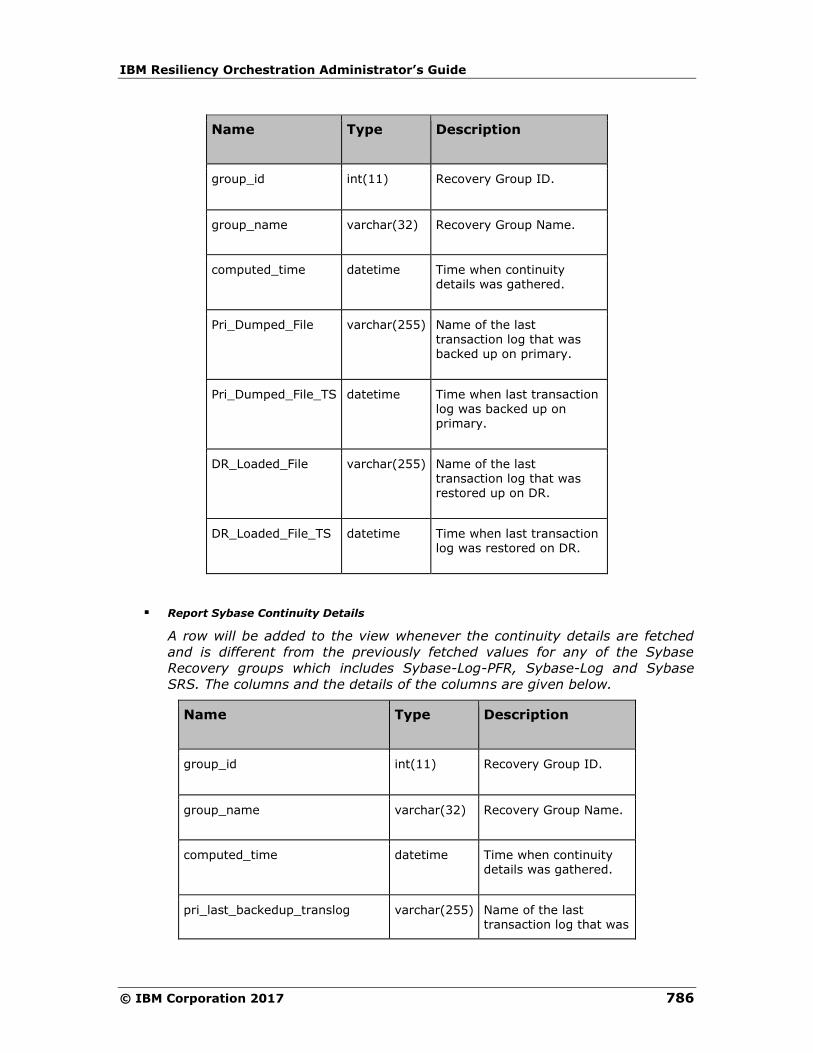
IBM Resiliency Orchestration Administrator’s Guide
© IBM Corporation 2017 786
Name Type Description
group_id int(11) Recovery Group ID.
group_name varchar(32) Recovery Group Name.
computed_time datetime Time when continuity details was gathered.
Pri_Dumped_File varchar(255) Name of the last
transaction log that was backed up on primary.
Pri_Dumped_File_TS datetime Time when last transaction log was backed up on primary.
DR_Loaded_File varchar(255) Name of the last transaction log that was restored up on DR.
DR_Loaded_File_TS datetime Time when last transaction log was restored on DR.
▪ Report Sybase Continuity Details
A row will be added to the view whenever the continuity details are fetched
and is different from the previously fetched values for any of the Sybase
Recovery groups which includes Sybase-Log-PFR, Sybase-Log and Sybase
SRS. The columns and the details of the columns are given below.
Name Type Description
group_id int(11) Recovery Group ID.
group_name varchar(32) Recovery Group Name.
computed_time datetime Time when continuity details was gathered.
pri_last_backedup_translog varchar(255) Name of the last transaction log that was
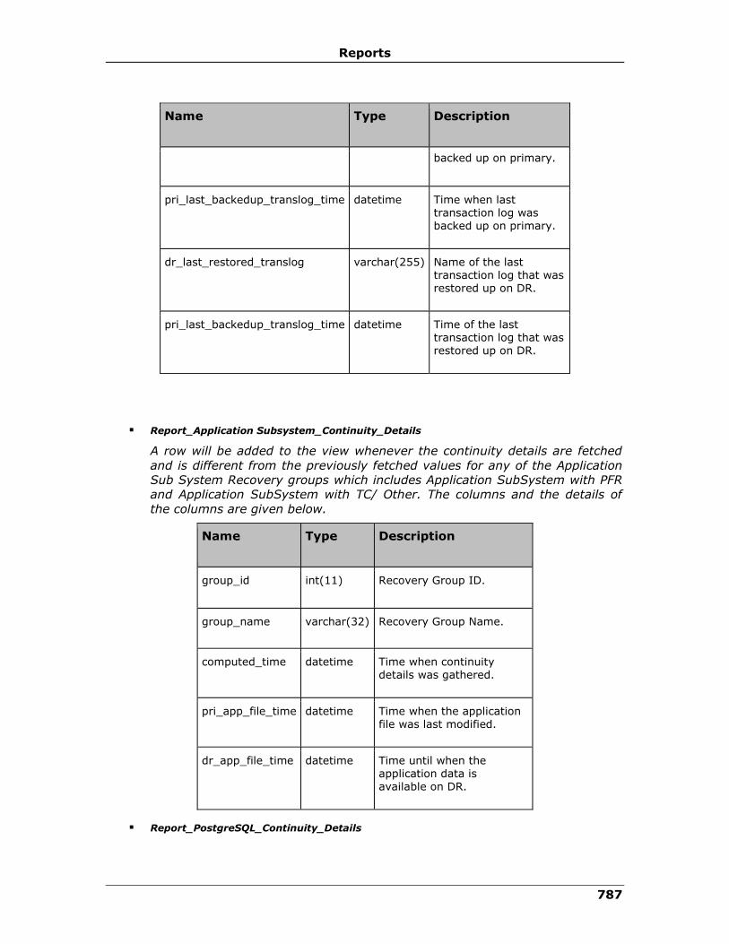
Reports
787
Name Type Description
backed up on primary.
pri_last_backedup_translog_time datetime Time when last transaction log was backed up on primary.
dr_last_restored_translog varchar(255) Name of the last transaction log that was restored up on DR.
pri_last_backedup_translog_time datetime Time of the last transaction log that was restored up on DR.
▪ Report_Application Subsystem_Continuity_Details
A row will be added to the view whenever the continuity details are fetched
and is different from the previously fetched values for any of the Application
Sub System Recovery groups which includes Application SubSystem with PFR
and Application SubSystem with TC/ Other. The columns and the details of
the columns are given below.
Name Type Description
group_id int(11) Recovery Group ID.
group_name varchar(32) Recovery Group Name.
computed_time datetime Time when continuity details was gathered.
pri_app_file_time datetime Time when the application file was last modified.
dr_app_file_time datetime Time until when the application data is available on DR.
▪ Report_PostgreSQL_Continuity_Details
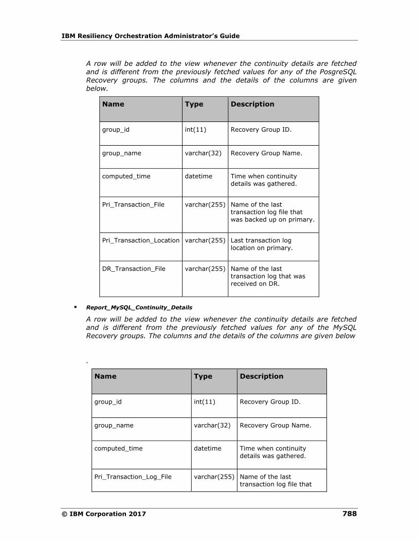
IBM Resiliency Orchestration Administrator’s Guide
© IBM Corporation 2017 788
A row will be added to the view whenever the continuity details are fetched
and is different from the previously fetched values for any of the PosgreSQL
Recovery groups. The columns and the details of the columns are given
below.
Name Type Description
group_id int(11) Recovery Group ID.
group_name varchar(32) Recovery Group Name.
computed_time datetime Time when continuity details was gathered.
Pri_Transaction_File varchar(255) Name of the last transaction log file that was backed up on primary.
Pri_Transaction_Location varchar(255) Last transaction log location on primary.
DR_Transaction_File varchar(255) Name of the last transaction log that was received on DR.
▪ Report_MySQL_Continuity_Details
A row will be added to the view whenever the continuity details are fetched
and is different from the previously fetched values for any of the MySQL
Recovery groups. The columns and the details of the columns are given below
.
Name Type Description
group_id int(11) Recovery Group ID.
group_name varchar(32) Recovery Group Name.
computed_time datetime Time when continuity details was gathered.
Pri_Transaction_Log_File varchar(255) Name of the last transaction log file that
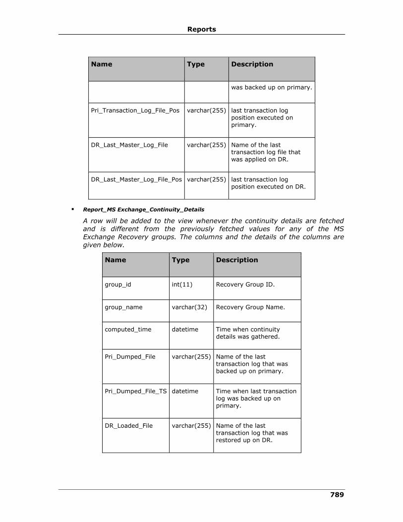
Reports
789
Name Type Description
was backed up on primary.
Pri_Transaction_Log_File_Pos varchar(255) last transaction log position executed on primary.
DR_Last_Master_Log_File varchar(255) Name of the last transaction log file that was applied on DR.
DR_Last_Master_Log_File_Pos varchar(255) last transaction log position executed on DR.
▪ Report_MS Exchange_Continuity_Details
A row will be added to the view whenever the continuity details are fetched
and is different from the previously fetched values for any of the MS
Exchange Recovery groups. The columns and the details of the columns are
given below.
Name Type Description
group_id int(11) Recovery Group ID.
group_name varchar(32) Recovery Group Name.
computed_time datetime Time when continuity details was gathered.
Pri_Dumped_File varchar(255) Name of the last transaction log that was backed up on primary.
Pri_Dumped_File_TS datetime Time when last transaction log was backed up on primary.
DR_Loaded_File varchar(255) Name of the last transaction log that was restored up on DR.
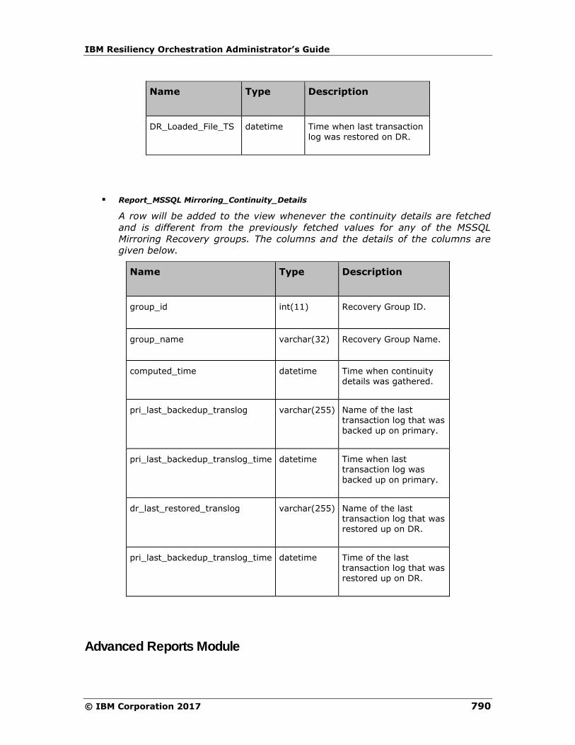
IBM Resiliency Orchestration Administrator’s Guide
© IBM Corporation 2017 790
Name Type Description
DR_Loaded_File_TS datetime Time when last transaction log was restored on DR.
▪ Report_MSSQL Mirroring_Continuity_Details
A row will be added to the view whenever the continuity details are fetched
and is different from the previously fetched values for any of the MSSQL
Mirroring Recovery groups. The columns and the details of the columns are
given below.
Name Type Description
group_id int(11) Recovery Group ID.
group_name varchar(32) Recovery Group Name.
computed_time datetime Time when continuity details was gathered.
pri_last_backedup_translog varchar(255) Name of the last transaction log that was
backed up on primary.
pri_last_backedup_translog_time datetime Time when last transaction log was
backed up on primary.
dr_last_restored_translog varchar(255) Name of the last transaction log that was restored up on DR.
pri_last_backedup_translog_time datetime Time of the last transaction log that was restored up on DR.
Advanced Reports Module

Reports
791
Advanced Reports module is a powerful, flexible, and easy to use reporting solution
that provides browser based, parameter driven, dynamic report generation and
flexible report scheduling capabilities.
Advanced Reports supports a variety of open source reporting engines, including
JasperReports, JFreeReport, JXLS, and Eclipse BIRT,these are used to provide
support a wide range of reporting requirements and capabilities. Advanced Reports
also supports QueryReports and ChartReports, easy to create SQL based reports that
do not require a predefined report definition.
Advanced Reports provides a web based report generation and administration
interface with the following features:
▪ Support for a wide variety of export formats including PDF, HTML, CSV, XLS,
RTF, and Image.
▪ Web based Administration of Users, Groups, Reports, Charts, Parameters, and
Data Sources
▪ Flexible Scheduling capabilities including Daily, Weekly, and Monthly options
and multiple recipients.
▪ Comprehensive Report Parameter support including Date, Text, List, Query,
and Boolean parameters.
▪ Fine-grained security controls access to Reports, Scheduling and
Administration functionality.
▪ Report Auditing tracks start time, duration, status, and user of every report
generated.
▪ Support for multiple JNDI or Connection Pool DataSources for use in
generating reports.
▪ Support for Drill Down reports and external application integration via secure
report generation URL.
▪ Click Reports, the link Launch Advanced Reports is enabled if Advanced
Reporter module is licensed.
Advanced Reports' report generation and scheduling capabilities are also available
directly via the ReportService, is a Service-oriented architecture (SOA) for report
generation and scheduling. The ReportService provides the ability to quickly add
reporting functionality to existing or new applications through a comprehensive and
flexible API exposed as a SOAP web service and to HTTP GET/PUT requests.
Note:
This Advanced Reports will be enabled only if any of the following conditions meet:
▪ Advanced Reporting feature License is enabled.
▪ Audit Logging feature License is enabled.

IBM Resiliency Orchestration Administrator’s Guide
© IBM Corporation 2017 792
Viewing a Report
Click IBM Resiliency Orchestration Server User Role Management to see the
privileges.
To view a report, perform the following steps:
1. Click REPORTS on the navigation bar. The Reports page appears.
2. Click Advanced Reports. A pop up window is displayed if the feature is
licensed, otherwise a pop-up is displayed with an error. The Advance Reporter
pop-up has Last updated timestamp and has two buttons, they are:
▪ Click Launch Advanced Reports button, to launch the IBM Resiliency
Orchestration Custom Reporting Solution.
OR
▪ Click Update Advanced Report Data button, to update the latest replication
data for the Recovery group.
3. Select a Report Group from the list of Report Groups. The Reports section
appears.
4. Select a Report from the list of reports.
5. Enter the Runtime parameter for the report if needed and click
OK. The Export Options section appears.
Field Description
Export Type Select the format in which you want to export the report.
You can export the report in PDF, HTML, and CSV format.
Run Click to view the report in the same window.
Run in New Window Click to run the report in a new window.
Note:
▪ You can click the Back to Groups link to go back to the page where all the
Report Groups are listed.
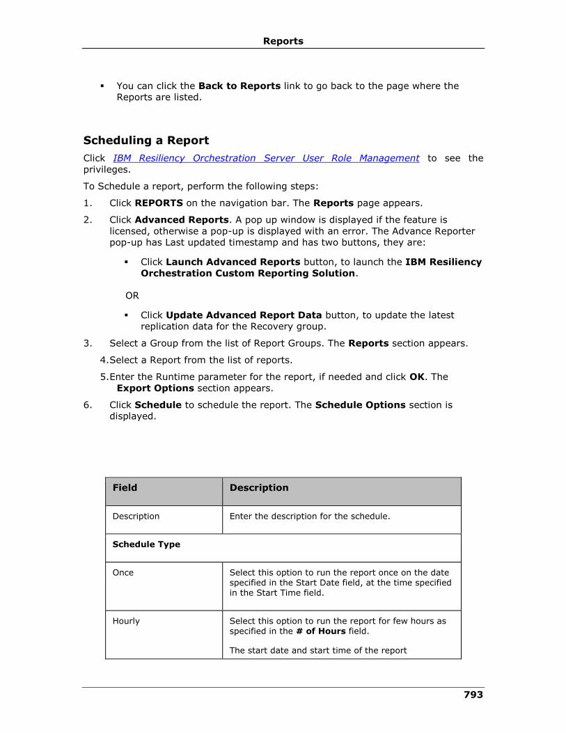
Reports
793
▪ You can click the Back to Reports link to go back to the page where the
Reports are listed.
Scheduling a Report
Click IBM Resiliency Orchestration Server User Role Management to see the
privileges.
To Schedule a report, perform the following steps:
1. Click REPORTS on the navigation bar. The Reports page appears.
2. Click Advanced Reports. A pop up window is displayed if the feature is
licensed, otherwise a pop-up is displayed with an error. The Advance Reporter
pop-up has Last updated timestamp and has two buttons, they are:
▪ Click Launch Advanced Reports button, to launch the IBM Resiliency
Orchestration Custom Reporting Solution.
OR
▪ Click Update Advanced Report Data button, to update the latest
replication data for the Recovery group.
3. Select a Group from the list of Report Groups. The Reports section appears.
4. Select a Report from the list of reports.
5. Enter the Runtime parameter for the report, if needed and click OK. The
Export Options section appears.
6. Click Schedule to schedule the report. The Schedule Options section is
displayed.
Field Description
Description Enter the description for the schedule.
Schedule Type
Once Select this option to run the report once on the date specified in the Start Date field, at the time specified in the Start Time field.
Hourly Select this option to run the report for few hours as specified in the # of Hours field.
The start date and start time of the report

IBM Resiliency Orchestration Administrator’s Guide
© IBM Corporation 2017 794
Field Description
generation is as specified in the Start Date field and the Start Time field respectively.
# of hours field represents the number of hours the report should be generated from the start time
everyday.
Daily Select this option to run the report daily starting from the date specified in the Start Date field, at the time specified in the Start Time field.
Weekdays Select this option to run the report on weekdays starting from the date specified in the Start Date field, at the time specified in the Start Time field.
Weekly Select this option to run the report weekly starting from the date specified in the Start Date field, at the time specified in the Start Time field.
Monthly Select this option to run the report monthly starting from the date specified in the Start Date field, at the time specified in the Start Time field.
Cron Select this option to run the report according to a CRON expression entered in the Cron Expression field.
This option allows tremendous flexibility in the scheduling of reports.
Start Date Select the start date to run report.
Start Time Select the start time to run report.
The time format is HH:MM:AM/PM
Cron Expression Enter the CRON expression if Cron Schedule Type is selected.
The expression must be set with caution so as not to overload system resources.
# of hours It represents the number of hours the report should be generated from the start time everyday.
In other words, you give the start time and then for
how many number of hours you want the report to
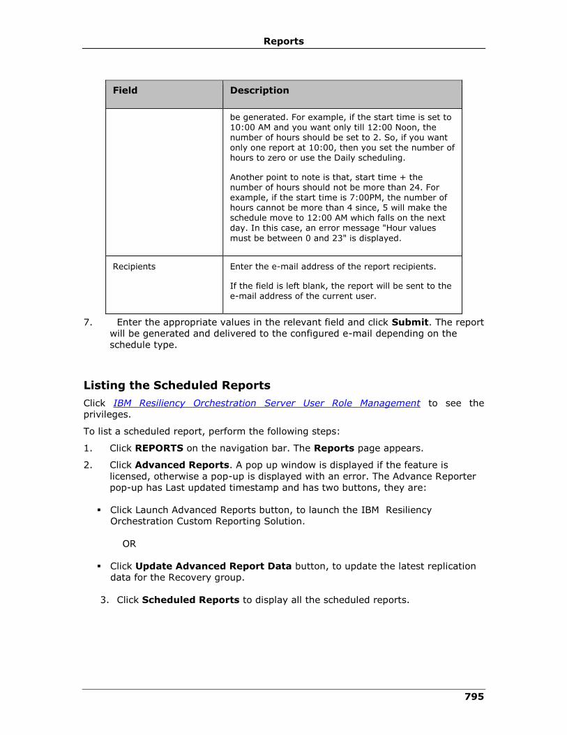
Reports
795
Field Description
be generated. For example, if the start time is set to 10:00 AM and you want only till 12:00 Noon, the number of hours should be set to 2. So, if you want only one report at 10:00, then you set the number of hours to zero or use the Daily scheduling.
Another point to note is that, start time + the number of hours should not be more than 24. For example, if the start time is 7:00PM, the number of hours cannot be more than 4 since, 5 will make the schedule move to 12:00 AM which falls on the next day. In this case, an error message "Hour values
must be between 0 and 23" is displayed.
Recipients Enter the e-mail address of the report recipients.
If the field is left blank, the report will be sent to the e-mail address of the current user.
7. Enter the appropriate values in the relevant field and click Submit. The report
will be generated and delivered to the configured e-mail depending on the
schedule type.
Listing the Scheduled Reports
Click IBM Resiliency Orchestration Server User Role Management to see the
privileges.
To list a scheduled report, perform the following steps:
1. Click REPORTS on the navigation bar. The Reports page appears.
2. Click Advanced Reports. A pop up window is displayed if the feature is
licensed, otherwise a pop-up is displayed with an error. The Advance Reporter
pop-up has Last updated timestamp and has two buttons, they are:
▪ Click Launch Advanced Reports button, to launch the IBM Resiliency
Orchestration Custom Reporting Solution.
OR
▪ Click Update Advanced Report Data button, to update the latest replication
data for the Recovery group.
3. Click Scheduled Reports to display all the scheduled reports.

IBM Resiliency Orchestration Administrator’s Guide
© IBM Corporation 2017 796
Modifying a Report Schedule
Click IBM Resiliency Orchestration Server User Role Management to see the
privileges.
To modify a scheduled report, perform the following steps:
1. Click REPORTS on the navigation bar. The Reports page appears.
2. Click Advanced Reports. A pop up window is displayed if the feature is
licensed, otherwise a pop-up is displayed with an error. The Advance Reporter
pop-up has Last updated timestamp and has two buttons, they are:
▪ Click Launch Advanced Reports button, to launch the IBM Resiliency
Orchestration Custom Reporting Solution.
OR
▪ Click Update Advanced Report Data button, to update the latest replication
data for the Recovery group.
2. Click Scheduled Reports to display the list of all scheduled reports. The user
is redirected to the Scheduled Reports page.
3. Click Update to edit the scheduled details.
The Schedule Options page is displayed:
Field Description
Description Modify the description for the schedule.
Schedule Type
Once Select this option to run the report once on the date specified in the Start Date field, at the time specified in the Start Time field.
Hourly Select this option to run the report for few hours as specified in the # of Hours field.
The start date and start time of the report
generation is as specified in the Start Date field and the Start Time field respectively.
# of hours field represents the number of hours
the report should be generated from the start time everyday.
Daily Select this option to run the report daily starting from the date specified in the Start Date field, at the time specified in the Start Time field.
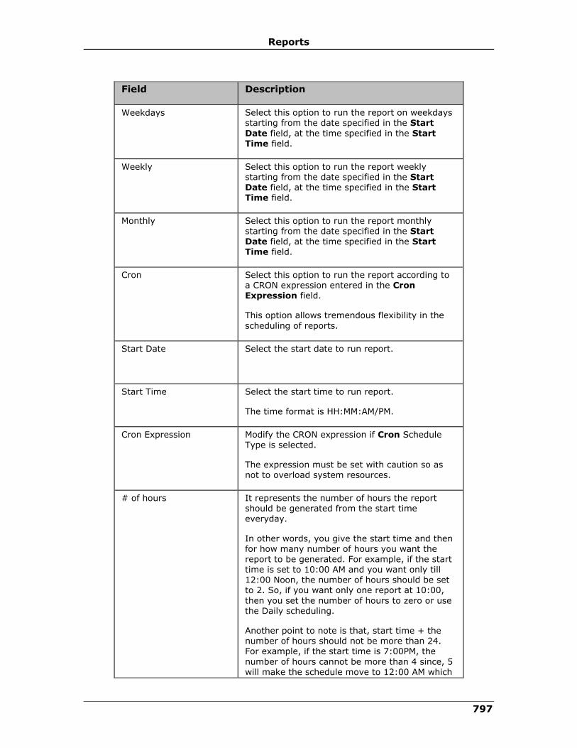
Reports
797
Field Description
Weekdays Select this option to run the report on weekdays starting from the date specified in the Start
Date field, at the time specified in the Start Time field.
Weekly Select this option to run the report weekly starting from the date specified in the Start Date field, at the time specified in the Start Time field.
Monthly Select this option to run the report monthly starting from the date specified in the Start
Date field, at the time specified in the Start Time field.
Cron Select this option to run the report according to a CRON expression entered in the Cron Expression field.
This option allows tremendous flexibility in the
scheduling of reports.
Start Date Select the start date to run report.
Start Time Select the start time to run report.
The time format is HH:MM:AM/PM.
Cron Expression Modify the CRON expression if Cron Schedule Type is selected.
The expression must be set with caution so as not to overload system resources.
# of hours It represents the number of hours the report should be generated from the start time everyday.
In other words, you give the start time and then for how many number of hours you want the
report to be generated. For example, if the start time is set to 10:00 AM and you want only till 12:00 Noon, the number of hours should be set to 2. So, if you want only one report at 10:00,
then you set the number of hours to zero or use the Daily scheduling.
Another point to note is that, start time + the number of hours should not be more than 24. For example, if the start time is 7:00PM, the
number of hours cannot be more than 4 since, 5 will make the schedule move to 12:00 AM which
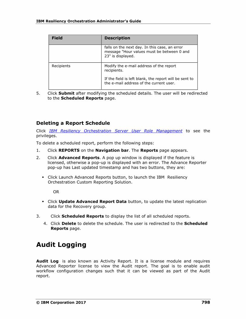
IBM Resiliency Orchestration Administrator’s Guide
© IBM Corporation 2017 798
Field Description
falls on the next day. In this case, an error message "Hour values must be between 0 and 23" is displayed.
Recipients Modify the e-mail address of the report recipients.
If the field is left blank, the report will be sent to the e-mail address of the current user.
5. Click Submit after modifying the scheduled details. The user will be redirected
to the Scheduled Reports page.
Deleting a Report Schedule
Click IBM Resiliency Orchestration Server User Role Management to see the
privileges.
To delete a scheduled report, perform the following steps:
1. Click REPORTS on the Navigation bar. The Reports page appears.
2. Click Advanced Reports. A pop up window is displayed if the feature is
licensed, otherwise a pop-up is displayed with an error. The Advance Reporter
pop-up has Last updated timestamp and has two buttons, they are:
▪ Click Launch Advanced Reports button, to launch the IBM Resiliency
Orchestration Custom Reporting Solution.
OR
▪ Click Update Advanced Report Data button, to update the latest replication
data for the Recovery group.
3. Click Scheduled Reports to display the list of all scheduled reports.
4. Click Delete to delete the schedule. The user is redirected to the Scheduled
Reports page.
Audit Logging
Audit Log is also known as Activity Report. It is a license module and requires
Advanced Reporter license to view the Audit report. The goal is to enable audit
workflow configuration changes such that it can be viewed as part of the Audit
report.

Reports
799
Audit Log is used to improve security. The system administrator can use the
activities stored in the audit log to check for suspicious patterns of activity in an
attempt to detect security violations. If security is violated, the audit log can be used
to determine how and when the problem occurred and perhaps the amount of
damage done. This information is very useful, both for recovery from the violation
and, possibly, in the development of better security measures to prevent future
problems.
IBM Resiliency Orchestration logs the following information:
▪ Date and time at which the operation was performed.
▪ Group (if applicable) on which the operation was performed.
▪ User name performing the operation.
▪ IP address of the browser machine connected to IBM Resiliency Orchestration
Server through which the operation is performed.
▪ Operations performed by IBM Resiliency Orchestration user.
IBM Resiliency Orchestration logs the following operations performed by the
user:
Workflow Execution:
▪ Start/Initiate Workflow
▪ Stop/Abort Workflow
▪ User interaction during workflow recovery after IBM server failure
▪ User interaction when Execution Dependent is set to previous action
▪ User interaction when Execution Mode is set to Manual
▪ User interaction when Inform completion is set to Success or All or
Failure
Workflow Configuration:
▪ Changes to action properties of an action
▪ Enabling/Disabling singlestep for workflow
▪ Enabling/Disabling skip action during execution
▪ Changes to key-value pair(s) of the workflow
▪ Edit workflow name/description
▪ Workflow import
▪ Adding an action/actiongroup to workflow
▪ Deleting an action/actiongroup from workflow
▪ Configuration changes to workflow schedule

IBM Resiliency Orchestration Administrator’s Guide
© IBM Corporation 2017 800
▪ Adding/Deleting a Business Process
▪ Adding/Deleting a Test Exercise
Note
▪ Audit Log's older than 365 days are purged. Purging is not configurable.
▪ When a group is deleted, corresponding Audit Log's will not be deleted along
with the group. However, the Audit Log will be purged after expiry as
mentioned above.
▪ Audit reports are shown only for Recovery Groups. With Application Groups,
Audit Log is available for all of the Recovery Groups belonging to the
Application Groups. But the audits are not grouped or categorized with
respect to Application Groups.
▪ Workflow configuration:
▪ Any changes to workflow schedule will be logged as one Audit Log. The
changes include one or all of the following:
▪ Enabling/disabling schedule.
▪ Changing schedule properties like recurrence frequency, date
range, start time etc.
▪ When workflow is imported, the Audit Log message will contain the
filename without path.
▪ Every time Save button is clicked in Workflow configuration page, it
will be treated as new changes and will be in Audit Log. The actual
changes (like diff) will not be done to detect whether changes really
exist. The following are a few which will be treated as workflow
configuration.
▪ Clicking on Save button without doing any changes.
▪ Deleted and added the same key-value for workflow.
▪ PFR action fileset filters are deleted and the same filters are
added in different order.
Viewing Audit Log Report
Click IBM Resiliency Orchestration Server User Role Management to see the
privileges.
To view Audit Log Report (also known as Activity Report), perform the following
steps:

Reports
801
1. Click REPORTS on the navigation bar. The Reports page appears.
2. Click Launch Advanced Reports. The launcher link is enabled if the feature is
licensed, otherwise the link is disabled. The IBM Resiliency Orchestration
Custom Reporting Solution window appears.
3. Click Activity Reports. The Reports section appears.
4. Select a Report from the list of reports. The Parameters page appears.
5. Click and select the start date if needed and click OK. The Export Options
page appears.
Field Description
Export Type Select the format in which you want to export the report.
You can export the report in PDF, HTML, and CSV format.
Run Click to view the report in the same window.
Run in New Window Click to run the report in a new window.
Schedule Click to schedule the report.
Note:
The Activity Report will not show non-user initiated workflows execution. For
example, for groups of solution type "...Other Replicator", IBM may periodically
execute ReplicationInfoWorkflow. For groups of solution type "...Full Database...",
IBM will periodically execute Pre and Post RPO workflows (if configured). These IBM
executed workflows will not appear in the Activity Report.
Scheduling Audit Log Report
Click IBM Resiliency Orchestration Server User Role Management to see the
privileges.
To schedule Audit Log Report (also known as Activity Report), perform the following
steps:
1. Click REPORTS on the navigation bar. The Reports page appears.
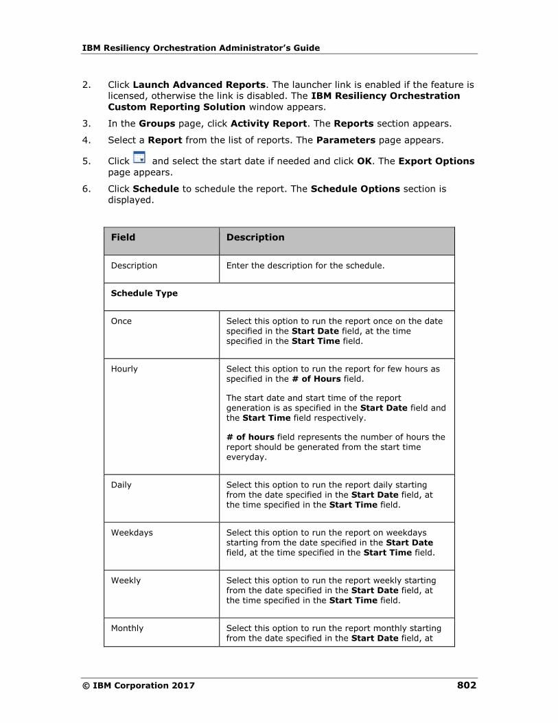
IBM Resiliency Orchestration Administrator’s Guide
© IBM Corporation 2017 802
2. Click Launch Advanced Reports. The launcher link is enabled if the feature is
licensed, otherwise the link is disabled. The IBM Resiliency Orchestration
Custom Reporting Solution window appears.
3. In the Groups page, click Activity Report. The Reports section appears.
4. Select a Report from the list of reports. The Parameters page appears.
5. Click and select the start date if needed and click OK. The Export Options
page appears.
6. Click Schedule to schedule the report. The Schedule Options section is
displayed.
Field Description
Description Enter the description for the schedule.
Schedule Type
Once Select this option to run the report once on the date specified in the Start Date field, at the time specified in the Start Time field.
Hourly Select this option to run the report for few hours as specified in the # of Hours field.
The start date and start time of the report generation is as specified in the Start Date field and the Start Time field respectively.
# of hours field represents the number of hours the report should be generated from the start time everyday.
Daily Select this option to run the report daily starting from the date specified in the Start Date field, at the time specified in the Start Time field.
Weekdays Select this option to run the report on weekdays starting from the date specified in the Start Date field, at the time specified in the Start Time field.
Weekly Select this option to run the report weekly starting from the date specified in the Start Date field, at the time specified in the Start Time field.
Monthly Select this option to run the report monthly starting from the date specified in the Start Date field, at
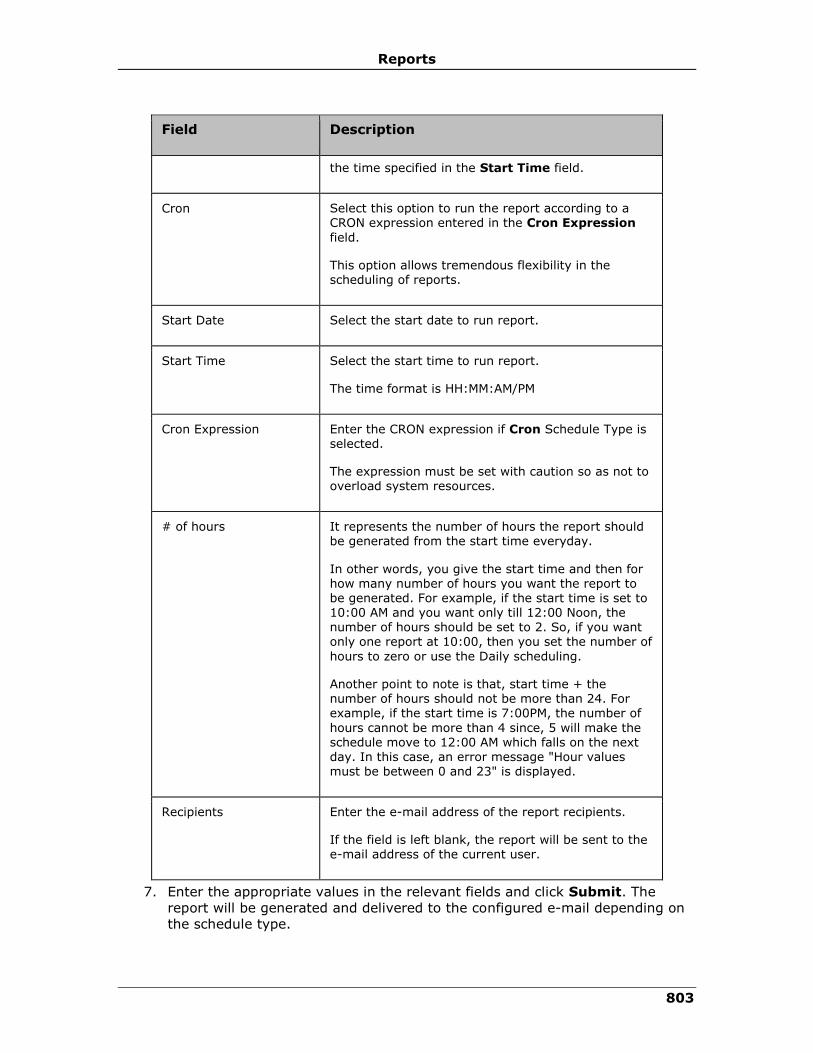
Reports
803
Field Description
the time specified in the Start Time field.
Cron Select this option to run the report according to a CRON expression entered in the Cron Expression
field.
This option allows tremendous flexibility in the scheduling of reports.
Start Date Select the start date to run report.
Start Time Select the start time to run report.
The time format is HH:MM:AM/PM
Cron Expression Enter the CRON expression if Cron Schedule Type is selected.
The expression must be set with caution so as not to overload system resources.
# of hours It represents the number of hours the report should be generated from the start time everyday.
In other words, you give the start time and then for how many number of hours you want the report to be generated. For example, if the start time is set to 10:00 AM and you want only till 12:00 Noon, the number of hours should be set to 2. So, if you want only one report at 10:00, then you set the number of
hours to zero or use the Daily scheduling.
Another point to note is that, start time + the number of hours should not be more than 24. For example, if the start time is 7:00PM, the number of
hours cannot be more than 4 since, 5 will make the schedule move to 12:00 AM which falls on the next day. In this case, an error message "Hour values must be between 0 and 23" is displayed.
Recipients Enter the e-mail address of the report recipients.
If the field is left blank, the report will be sent to the e-mail address of the current user.
7. Enter the appropriate values in the relevant fields and click Submit. The
report will be generated and delivered to the configured e-mail depending on
the schedule type.

IBM Resiliency Orchestration Administrator’s Guide
© IBM Corporation 2017 804
Listing Scheduled Audit Log Reports
Click IBM Resiliency Orchestration Server User Role Management to see the
privileges.
To view the scheduled Audit Log Reports (also known as Activity Report), perform
the following steps:
1. Click REPORTS on the navigation bar. The Reports page
appears.
2. Click Launch Advanced Reports. The launcher link is enabled
if the feature is licensed, otherwise the link is disabled. The IBM
Resiliency Orchestration Custom Reporting Solution window
appears.
3. Click the Scheduled Reports button at the top right corner to
view all the scheduled reports.
Modifying Audit Log Report Schedule
Click IBM Resiliency Orchestration Server User Role Management to see the
privileges.
To modify Audit Log Report (also known as Activity Report) schedule, perform the
following steps:
1. Click REPORTS on the navigation bar. The Reports page appears.
2. Click Launch Advanced Reports. The launcher link is enabled if the feature is
licensed, otherwise the link is disabled. The IBM Resiliency Orchestration
Custom Reporting Solution window appears.
3. Click Scheduled Reports to display the list of all scheduled reports.
4. Click Update corresponding to the scheduled report to be updated. The user is
redirected to the Schedule Options section.
5. Modify the required fields:
Field Description
Description Modify the description for the schedule.
Schedule Type
Once Select this option to run the report once on the date specified in the Start Date field, at the time specified in the Start Time field.
Hourly Select this option to run the report for few hours

Reports
805
Field Description
as specified in the # of Hours field.
The start date and start time of the report generation is as specified in the Start Date field and the Start Time field respectively.
# of hours field represents the number of hours the report should be generated from the start time everyday.
Daily Select this option to run the report daily starting from the date specified in the Start Date field,
at the time specified in the Start Time field.
Weekdays Select this option to run the report on weekdays starting from the date specified in the Start Date field, at the time specified in the Start Time field.
Weekly Select this option to run the report weekly starting from the date specified in the Start Date field, at the time specified in the Start Time field.
Monthly Select this option to run the report monthly starting from the date specified in the Start Date field, at the time specified in the Start
Time field.
Cron Select this option to run the report according to a CRON expression entered in the Cron Expression field.
This option allows tremendous flexibility in the scheduling of reports.
Start Date Select the start date to run report.
Start Time Select the start time to run report.
The time format is HH:MM:AM/PM
Cron Expression Modify the CRON expression if Cron Schedule Type is selected.
The expression must be set with caution so as not to overload system resources.
# of hours It represents the number of hours the report should be generated from the start time
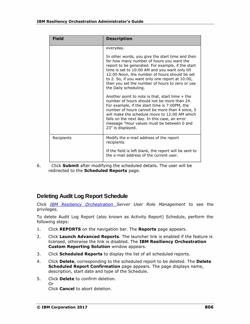
IBM Resiliency Orchestration Administrator’s Guide
© IBM Corporation 2017 806
Field Description
everyday.
In other words, you give the start time and then for how many number of hours you want the report to be generated. For example, if the start
time is set to 10:00 AM and you want only till 12:00 Noon, the number of hours should be set to 2. So, if you want only one report at 10:00, then you set the number of hours to zero or use the Daily scheduling.
Another point to note is that, start time + the number of hours should not be more than 24.
For example, if the start time is 7:00PM, the number of hours cannot be more than 4 since, 5 will make the schedule move to 12:00 AM which falls on the next day. In this case, an error
message "Hour values must be between 0 and 23" is displayed.
Recipients Modify the e-mail address of the report recipients.
If the field is left blank, the report will be sent to the e-mail address of the current user.
6. Click Submit after modifying the scheduled details. The user will be
redirected to the Scheduled Reports page.
Deleting Audit Log Report Schedule
Click IBM Resiliency Orchestration Server User Role Management to see the
privileges.
To delete Audit Log Report (also known as Activity Report) Schedule, perform the
following steps:
1. Click REPORTS on the navigation bar. The Reports page appears.
2. Click Launch Advanced Reports. The launcher link is enabled if the feature is
licensed, otherwise the link is disabled. The IBM Resiliency Orchestration
Custom Reporting Solution window appears.
3. Click Scheduled Reports to display the list of all scheduled reports.
4. Click Delete, corresponding to the scheduled report to be deleted. The Delete
Scheduled Report Confirmation page appears. The page displays name,
description, start date and type of the Schedule.
5. Click Delete to confirm deletion.
Or
Click Cancel to abort deletion.

Reports
807

IBM Resiliency Orchestration Administrator’s Guide
© Copyright IBM Corporation 2017
Discovery
Sites
Setting Up Sites
This chapter describes how to work with sites in the DR environment.
This section explains the following:
Adding Sites
Modifying Sites
Deleting Sites
Site Listing
Adding Organization
1. Login to CLI IBM Resiliency Orchestration server
2. Go to $EAMSROOT/bin
3. Unzip cdrm-ws-testclient.zip file
4. Go to /testclient/shellscripts
./addsubscriber.sh < Resiliency_Orchestration_IP> <Username> <Password> <Login Override>
For ex. ./addsubscriber.sh 192.168.20.69 ResiliencyOrchestrationAdmin Drmadmin123$ yes
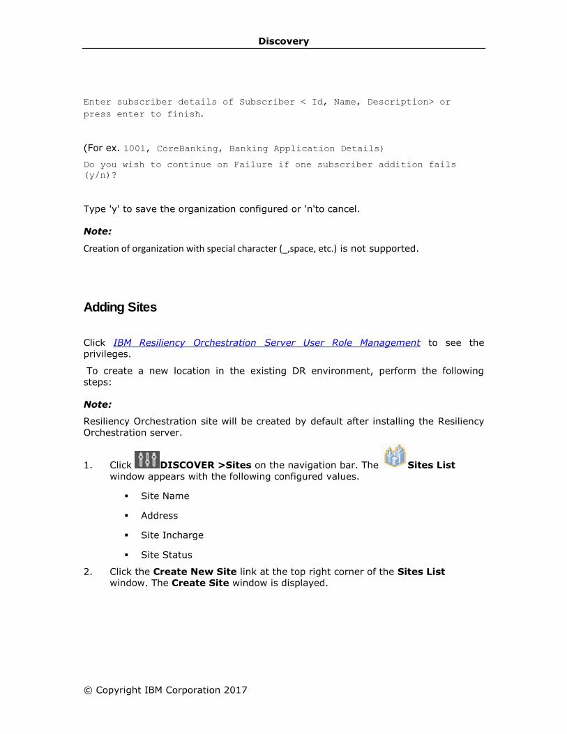
Discovery
© Copyright IBM Corporation 2017
Enter subscriber details of Subscriber < Id, Name, Description> or
press enter to finish.
(For ex. 1001, CoreBanking, Banking Application Details)
Do you wish to continue on Failure if one subscriber addition fails
(y/n)?
Type 'y' to save the organization configured or 'n'to cancel.
Note:
Creation of organization with special character (_,space, etc.) is not supported.
Adding Sites
Click IBM Resiliency Orchestration Server User Role Management to see the
privileges.
To create a new location in the existing DR environment, perform the following
steps:
Note:
Resiliency Orchestration site will be created by default after installing the Resiliency
Orchestration server.
1. Click DISCOVER >Sites on the navigation bar. The Sites List
window appears with the following configured values.
▪ Site Name
▪ Address
▪ Site Incharge
▪ Site Status
2. Click the Create New Site link at the top right corner of the Sites List
window. The Create Site window is displayed.
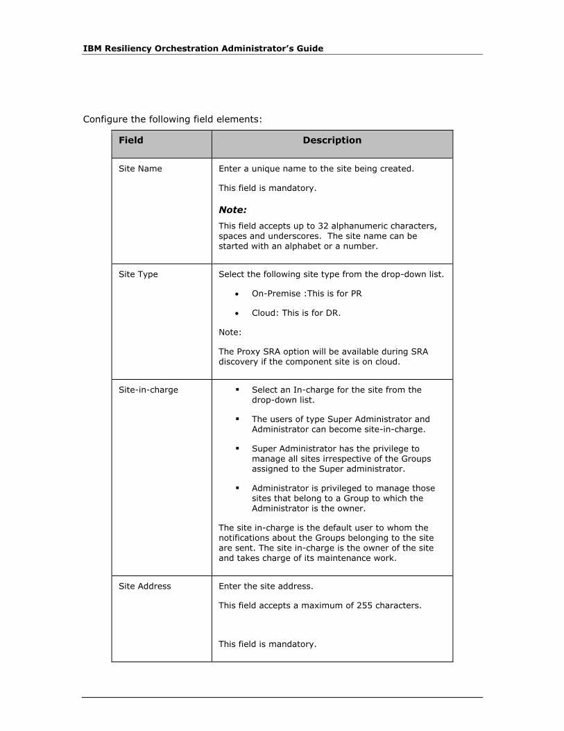
IBM Resiliency Orchestration Administrator’s Guide
Configure the following field elements:
Field Description
Site Name Enter a unique name to the site being created.
This field is mandatory.
Note:
This field accepts up to 32 alphanumeric characters,
spaces and underscores. The site name can be started with an alphabet or a number.
Site Type Select the following site type from the drop-down list.
• On-Premise :This is for PR
• Cloud: This is for DR.
Note:
The Proxy SRA option will be available during SRA discovery if the component site is on cloud.
Site-in-charge ▪ Select an In-charge for the site from the drop-down list.
▪ The users of type Super Administrator and Administrator can become site-in-charge.
▪ Super Administrator has the privilege to manage all sites irrespective of the Groups assigned to the Super administrator.
▪ Administrator is privileged to manage those sites that belong to a Group to which the Administrator is the owner.
The site in-charge is the default user to whom the notifications about the Groups belonging to the site
are sent. The site in-charge is the owner of the site and takes charge of its maintenance work.
Site Address Enter the site address.
This field accepts a maximum of 255 characters.
This field is mandatory.

Discovery
© Copyright IBM Corporation 2017
3. Click Save to add the site.
OR
Click Cancel to quit the current operation.
4. On successfully adding the site, a message box is displayed.
5. Click OK in the message box to return to the Sites List page.
Modifying Sites
Click IBM Resiliency Orchestration Server User Role Management to see the
privileges.
To modify a Site, perform the following steps:
1. Click DISCOVER > Sites on the navigation bar. The Sites List window
appears with the following configured values.
▪ Site Name
▪ Address
▪ Site Incharge
▪ Site Status
2. Click icon corresponding to the site that you want to modify. This opens Edit
Site page. The site details can not be modified by users with Operator
privileges. Refer Adding Sites for field description.
Note:
Site name (city) cannot be modified.
3. Make the required changes in the relevant field.
4. Click Save to save the modifications.
OR
Click Cancel to quit current operation.
5. On successful modification, a message box is displayed. Click OK to return to
the Sites List page.
IBM Resiliency Orchestration Administrator’s Guide
Deleting Site
Click IBM Resiliency Orchestration Server User Role Management to see the
privileges.
A site cannot be deleted, if there are components associated with it.
To delete a Site, perform the following steps:
1. Click DISCOVER > Sites on the navigation bar. The Sites List page appears
with the following configured values.
▪ Site Name
▪ Address
▪ Site Incharge
▪ Site Status
2. Click the icon corresponding to the site that you want to delete. A message
box is displayed confirming the deletion.
3. Click OK.
Site Listing
To view the sites created or available in a DR environment, click DISCOVER > Sites
on the navigation bar. You can also navigate to the Site List page by clicking List
View link at the top right corner of the Sites area on the Dashboard window.
Click IBM Resiliency Orchestration Server User Role Management to see the
privileges.
The Sites List page displays following details:
Field Description
Site Name Displays the name of the site.
ADDRESS Displays the site address.
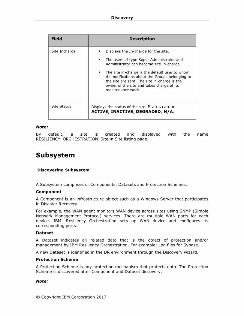
Discovery
© Copyright IBM Corporation 2017
Field Description
Site Incharge ▪ Displays the In-charge for the site.
▪ The users of type Super Administrator and Administrator can become site-in-charge.
▪ The site in-charge is the default user to whom the notifications about the Groups belonging to
the site are sent. The site in-charge is the owner of the site and takes charge of its maintenance work.
Site Status Displays the status of the site. Status can be
ACTIVE, INACTIVE, DEGRADED, N/A.
Note:
By default, a site is created and displayed with the name
RESILIENCY_ORCHESTRATION_Site in Site listing page.
Subsystem
Discovering Subsystem
A Subsystem comprises of Components, Datasets and Protection Schemes.
Component
A Component is an infrastructure object such as a Windows Server that participates
in Disaster Recovery.
For example, the WAN agent monitors WAN device across sites using SNMP (Simple
Network Management Protocol) services. There are multiple WAN ports for each
device. IBM Resiliency Orchestration sets up WAN device and configures its
corresponding ports.
Dataset
A Dataset indicates all related data that is the object of protection and/or
management by IBM Resiliency Orchestration. For example: Log files for Sybase.
A new Dataset is identified in the DR environment through the Discovery wizard.
Protection Scheme
A Protection Scheme is any protection mechanism that protects data. The Protection
Scheme is discovered after Component and Dataset discovery.
Note:
IBM Resiliency Orchestration Administrator’s Guide
If these subsystems are set up but their associated agents are not connected, the
subsystems status would be shown as Unknown. When agents will be connected, the
status will be updated with status of underlying system.
Auto Discovery
Auto Discovery helps you setup the Protection Scheme or Dataset automatically.
Compared to the manual discovery, auto discovery is an easy method, as it is
performed by IBM Resiliency Orchestration™ itself. Ensure that you have set up
respective agents before performing auto discovery.
This version of IBM Resiliency Orchestration supports auto discovery for the following
subsystems:
Dataset
▪ MSSQL
▪ Oracle
▪ PostgreSQL
▪ MySQL
▪ MS Exchange
▪ Sybase
▪ App Subsystem
Protection Scheme
▪ PFR
▪ Oracle DataGuard
▪ Hitachi Replication
▪ PostgreSQL SR
▪ EMC SRDF Replication
▪ Sybase Replication Server
▪ HP XP Replication
▪ MySQL SR
▪ MS Exchange SR
▪ NetApp SnapMirror
Credentials

Discovery
© Copyright IBM Corporation 2017
Click IBM Resiliency Orchestration Server User Role Management to see the
privileges.
Click DISCOVER > Credentials on the navigation bar. The Credentials page
appears. The Credentials page now allows the creation of new Credential and
Vault.
Create New Credential Using Password
The following are steps for creating new credential using password:
1. Select DISCOVER > Credentials on the navigation bar. The Credentials
page displays.
2. Click Create Credential link in the top right corner. The Create
Credential page displays.
3. Click Password in Authentication Method.
4. Enter the User Name and Password.
5. Choose the Protocol from the drop-down list as displayed:
▪ wmi: If the server being managed is Windows.
▪ ssh: If the server being managed is Unix/Linux.
Note:
Depending on the selection of the Protocol, the Port No is displayed.
6. Enter the Label.
7. Click Save.
Create New Credential Using SSH
The following are steps for creating new credential using SSH:
1. Select DISCOVER > Credentials on the navigation bar. The Credentials
page displays.
2. Click Create Credential link in the top right corner. The Create
Credential page displays.
3. Click SSH in Authentication Method.
4. Enter the User Name and then click Choose File to specify the location of
PrivateKey file and select the file. The PrivateKey file name is displayed in
KeyPair field. Refer to Create SSH Key for details to create a SSH key.
5. By default, the ssh protocol is selected and Port No is displayed.
6. Enter the Label.
7. Click Save.

IBM Resiliency Orchestration Administrator’s Guide
To view the credentials, perform the following steps:
1. Click DISCOVER > Credentials on the navigation bar. The Credentials page
appears.
2. Under Credential List section, click the label to view the Credential details.
Note:
The Objects Using field displays the subsystems which are using the credential.
To modify a credential, perform the following steps:
1. Click the button, the user will be directed to Edit Credentials page.
You can modify the User Name, Password, Port No. and Label.
2. Click Save after making the changes.
OR
Click Cancel to return to the Credentials page.
To delete a credential, perform the following steps:
1. Click DISCOVER > Credentials on the navigation bar. The Credentials page
appears.
2. Click the Delete icon to delete a credential.
If any credential is used by a subsystem, the user cannot delete it. The
credential has to be detached from the subsystem, in order to delete it.
Note:
Apart from the Password field, the rest of the fields are mandatory.
The subsystem can be a component, dataset or protection scheme.
Port number can be edited only if the protocol selected is "ssh".
Create New Vault for CyberArk
To create a new Vault
1. Click DISCOVER > Credentials on the navigation bar. The Credentials page
appears.
2. Click Create New Vault link in the top right corner. The Create Vault page
appears with the following fields:
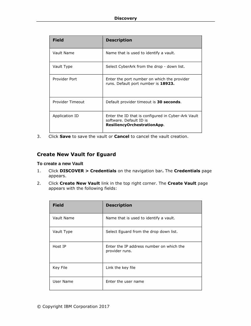
Discovery
© Copyright IBM Corporation 2017
Field Description
Vault Name Name that is used to identify a vault.
Vault Type Select CyberArk from the drop - down list.
Provider Port
Enter the port number on which the provider runs. Default port number is 18923.
Provider Timeout Default provider timeout is 30 seconds.
Application ID Enter the ID that is configured in Cyber-Ark Vault software. Default ID is ResiliencyOrchestrationApp.
3. Click Save to save the vault or Cancel to cancel the vault creation.
Create New Vault for Eguard
To create a new Vault
1. Click DISCOVER > Credentials on the navigation bar. The Credentials page
appears.
2. Click Create New Vault link in the top right corner. The Create Vault page
appears with the following fields:
Field Description
Vault Name Name that is used to identify a vault.
Vault Type Select Eguard from the drop down list.
Host IP
Enter the IP address number on which the provider runs.
Key File Link the key file
User Name Enter the user name

IBM Resiliency Orchestration Administrator’s Guide
Field Description
Time Required (minutes)
To view the Vault
1. Click DISCOVER > Credentials on the navigation bar. The Credentials page
appears.
2. Under Vault List section, click the Vault Name to view the Vault details.
To delete a Vault
1. Click DISCOVER > Credentials on the navigation bar. The Credentials page
appears.
2. Click the corresponding Delete icon to delete a Vault.
Agent Upgrade
Configuration
When Agentless model is used, Resiliency Orchestration software needs additional
configuration.
As part of subsystem discovery, user needs to provide additional information which is
used to access customer servers remotely. This include credential information to
access a customer server. These are described in subsystem discovery page in detail.
If multiple servers can be accessed using same credential information, Resiliency
Orchestration provides option to enter the credentials once and then can be attached
to any number of subsystems. This is explained under Credentials.
To use IBM Resiliency Orchestration as an Agentless model, user needs to discover
Resiliency Orchestration server machine as a component and start an agent on the
Resiliency Orchestration server system.
Refer Management, to start agent and refer Configuration, to discover a component.
Once this step is done, user can go ahead with other subsystems and group
discovery.
Prerequisites
The following are prerequisites for Agent upgrade:
a. The following ports should be opened between the Resiliency Orchestration
Server and agents:
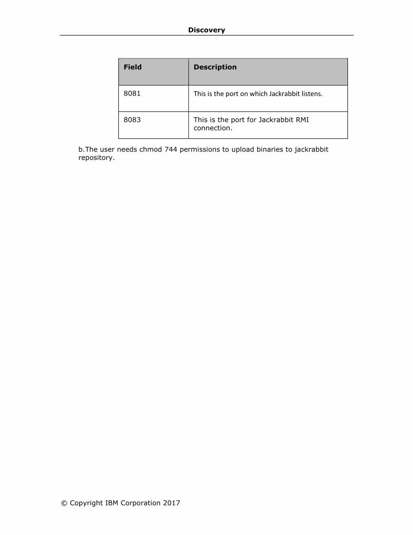
Discovery
© Copyright IBM Corporation 2017
Field Description
8081 This is the port on which Jackrabbit listens.
8083 This is the port for Jackrabbit RMI
connection.
b. The user needs chmod 744 permissions to upload binaries to jackrabbit
repository.
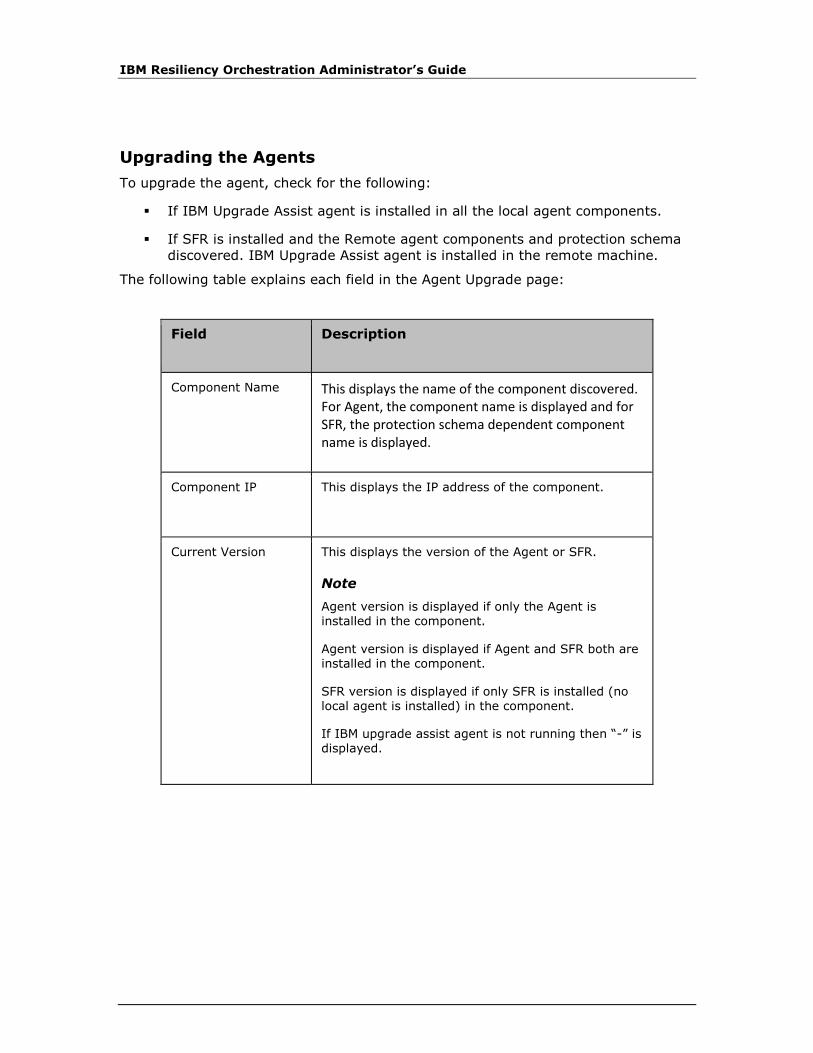
IBM Resiliency Orchestration Administrator’s Guide
Upgrading the Agents
To upgrade the agent, check for the following:
▪ If IBM Upgrade Assist agent is installed in all the local agent components.
▪ If SFR is installed and the Remote agent components and protection schema
discovered. IBM Upgrade Assist agent is installed in the remote machine.
The following table explains each field in the Agent Upgrade page:
Field Description
Component Name This displays the name of the component discovered. For Agent, the component name is displayed and for SFR, the protection schema dependent component name is displayed.
Component IP This displays the IP address of the component.
Current Version
This displays the version of the Agent or SFR.
Note
Agent version is displayed if only the Agent is installed in the component.
Agent version is displayed if Agent and SFR both are installed in the component.
SFR version is displayed if only SFR is installed (no local agent is installed) in the component.
If IBM upgrade assist agent is not running then “-” is displayed.
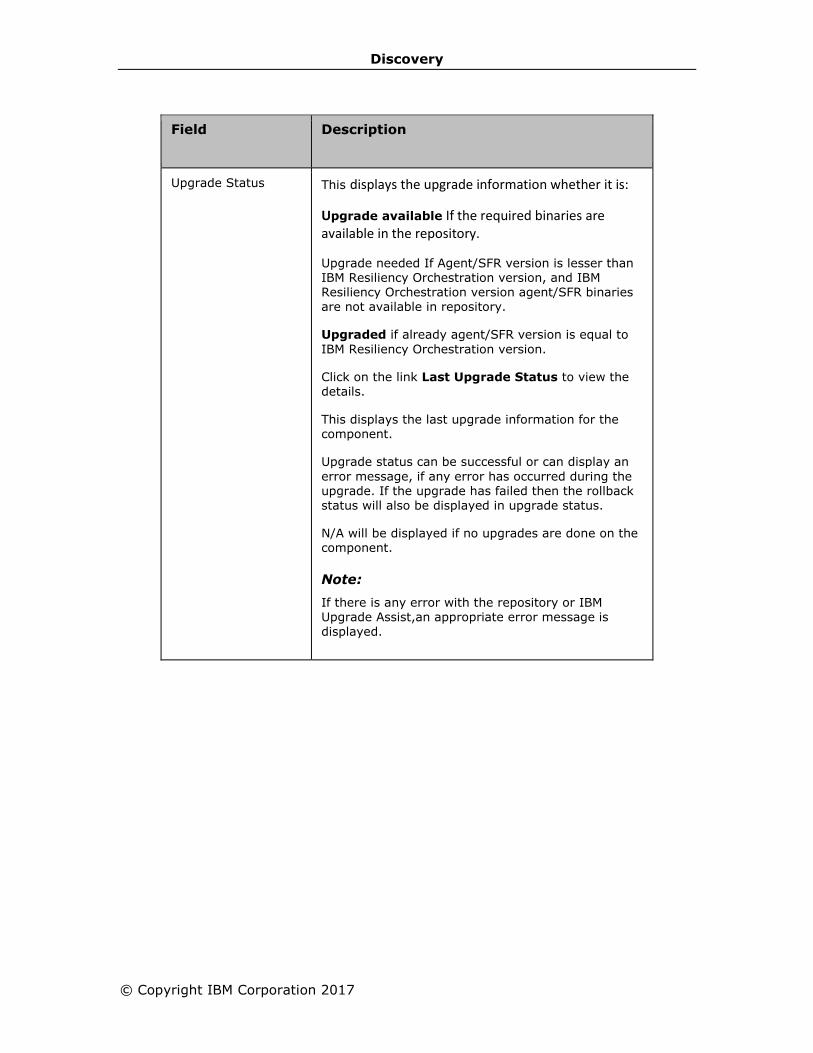
Discovery
© Copyright IBM Corporation 2017
Field Description
Upgrade Status This displays the upgrade information whether it is:
Upgrade available If the required binaries are available in the repository.
Upgrade needed If Agent/SFR version is lesser than IBM Resiliency Orchestration version, and IBM Resiliency Orchestration version agent/SFR binaries are not available in repository.
Upgraded if already agent/SFR version is equal to
IBM Resiliency Orchestration version.
Click on the link Last Upgrade Status to view the details.
This displays the last upgrade information for the component.
Upgrade status can be successful or can display an
error message, if any error has occurred during the upgrade. If the upgrade has failed then the rollback status will also be displayed in upgrade status.
N/A will be displayed if no upgrades are done on the component.
Note:
If there is any error with the repository or IBM Upgrade Assist,an appropriate error message is displayed.
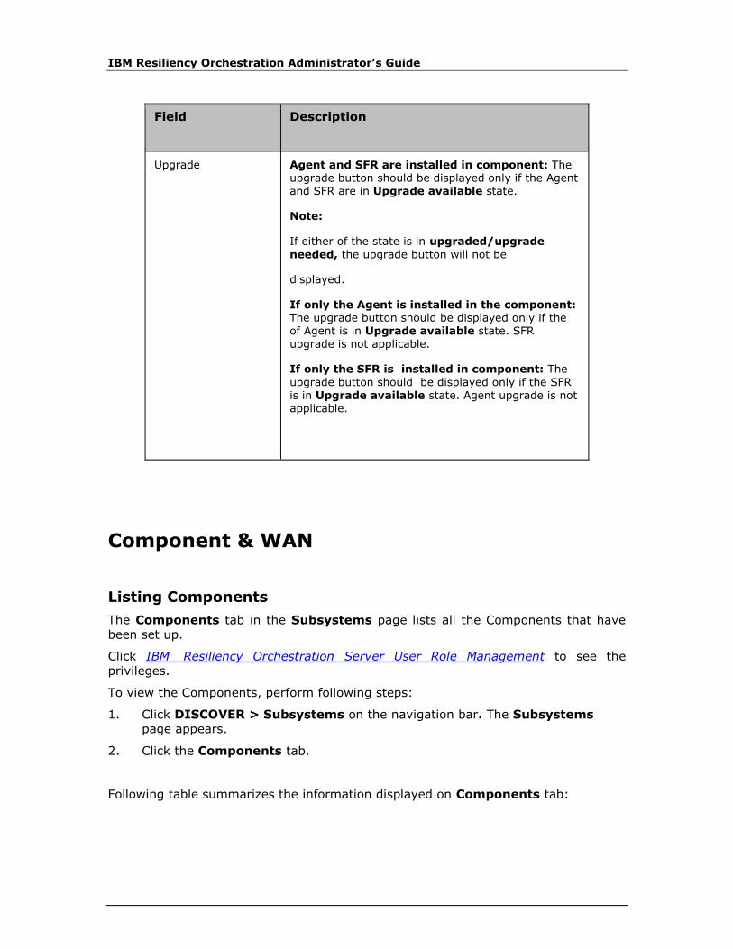
IBM Resiliency Orchestration Administrator’s Guide
Field Description
Upgrade Agent and SFR are installed in component: The upgrade button should be displayed only if the Agent and SFR are in Upgrade available state.
Note:
If either of the state is in upgraded/upgrade
needed, the upgrade button will not be
displayed.
If only the Agent is installed in the component: The upgrade button should be displayed only if the of Agent is in Upgrade available state. SFR upgrade is not applicable.
If only the SFR is installed in component: The
upgrade button should be displayed only if the SFR is in Upgrade available state. Agent upgrade is not applicable.
Component & WAN
Listing Components
The Components tab in the Subsystems page lists all the Components that have
been set up.
Click IBM Resiliency Orchestration Server User Role Management to see the
privileges.
To view the Components, perform following steps:
1. Click DISCOVER > Subsystems on the navigation bar. The Subsystems
page appears.
2. Click the Components tab.
Following table summarizes the information displayed on Components tab:
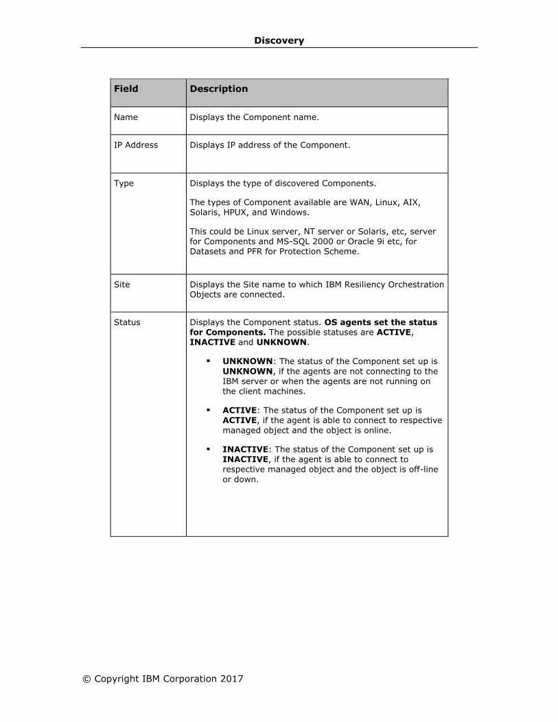
Discovery
© Copyright IBM Corporation 2017
Field Description
Name Displays the Component name.
IP Address Displays IP address of the Component.
Type Displays the type of discovered Components.
The types of Component available are WAN, Linux, AIX, Solaris, HPUX, and Windows.
This could be Linux server, NT server or Solaris, etc, server for Components and MS-SQL 2000 or Oracle 9i etc, for Datasets and PFR for Protection Scheme.
Site Displays the Site name to which IBM Resiliency Orchestration Objects are connected.
Status Displays the Component status. OS agents set the status for Components. The possible statuses are ACTIVE, INACTIVE and UNKNOWN.
▪ UNKNOWN: The status of the Component set up is
UNKNOWN, if the agents are not connecting to the
IBM server or when the agents are not running on the client machines.
▪ ACTIVE: The status of the Component set up is ACTIVE, if the agent is able to connect to respective
managed object and the object is online.
▪ INACTIVE: The status of the Component set up is INACTIVE, if the agent is able to connect to respective managed object and the object is off-line
or down.
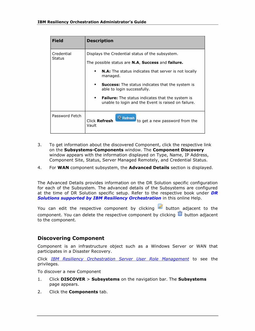
IBM Resiliency Orchestration Administrator’s Guide
Field Description
Credential Status
Displays the Credential status of the subsystem.
The possible status are N.A, Success and failure.
▪ N.A: The status indicates that server is not locally managed.
▪ Success: The status indicates that the system is able to login successfully.
▪ Failure: The status indicates that the system is
unable to login and the Event is raised on failure.
Password Fetch
Click Refresh to get a new password from the Vault
3. To get information about the discovered Component, click the respective link
on the Subsystems-Components window. The Component Discovery
window appears with the information displayed on Type, Name, IP Address,
Component Site, Status, Server Managed Remotely, and Credential Status.
4. For WAN component subsystem, the Advanced Details section is displayed.
The Advanced Details provides information on the DR Solution specific configuration
for each of the Subsystem. The advanced details of the Subsystems are configured
at the time of DR Solution specific setup. Refer to the respective book under DR
Solutions supported by IBM Resiliency Orchestration in this online Help.
You can edit the respective component by clicking button adjacent to the
component. You can delete the respective component by clicking button adjacent
to the component.
Discovering Component
Component is an infrastructure object such as a Windows Server or WAN that
participates in a Disaster Recovery.
Click IBM Resiliency Orchestration Server User Role Management to see the
privileges.
To discover a new Component
1. Click DISCOVER > Subsystems on the navigation bar. The Subsystems
page appears.
2. Click the Components tab.

Discovery
© Copyright IBM Corporation 2017
3. Select the type of Component Subsystem from the Create New drop-down list
at the top right corner of the Subsystems page. The drop-down list displays all
the Component Subsystems that can be created.
4. Click Go. The New Component Discovery page appears. The Subsystems
side bar page displays list of all the Components already discovered.
Provide the information for the following fields to configure the Component:
Field Description
Type Select the type of component from drop-down list.
The component could be a Wan server, AIX server, HPUX server, Linux server, Windows server, or Solaris server.
Name
By-default,the name is auto populated which is a combination of component type and server name/component ip.
OR
Provide a unique name for the component.
Note:
This field accepts alphanumeric characters, and underscores only. This field must start with an alphabetic character, and is limited to 32
characters. Name should not contain spaces.
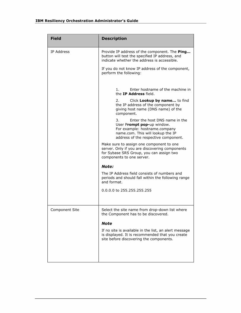
IBM Resiliency Orchestration Administrator’s Guide
Field Description
IP Address
Provide IP address of the component. The Ping... button will test the specified IP address, and indicate whether the address is accessible.
If you do not know IP address of the component, perform the following:
1. Enter hostname of the machine in the IP Address field.
2. Click Lookup by name... to find the IP address of the component by giving host name (DNS name) of the
component.
3. Enter the host DNS name in the User Prompt pop-up window. For example: hostname.company name.com. This will lookup the IP address of the respective component.
Make sure to assign one component to one
server. Only if you are discovering components for Sybase SRS Group, you can assign two components to one server.
Note:
The IP Address field consists of numbers and periods and should fall within the following range
and format.
0.0.0.0 to 255.255.255.255
Component Site
Select the site name from drop-down list where the Component has to be discovered.
Note
If no site is available in the list, an alert message is displayed. It is recommended that you create site before discovering the components.

Discovery
© Copyright IBM Corporation 2017
Field Description
Server Managed Remotely
By default,Server Managed Remotely check box is selected.
Note
Deselect the checkbox, to manage the Server by
installing Agents on that Server; A message, "Please install agents (if not already installed) on this server and start agent" is displayed.
Refer to Installation guide for more information.
Credentials This will be activated only on selecting the Server Managed Remotely check box. The following credentials will be available, select any one based on the requirement:
▪ Add New Credentials: Enter the UserName and Password. The UserName
field will include the Domain Name also. By default, the Port No (SSH) will be displayed. It is created only for specified users. A Fetch from vault check box is
displayed along. The fields Safe Name, Object Name and a vault list will be
enabled on selecting the Fetch from vault check box.
▪ Other credentials are displayed which are created under Group credentials. For example: Unix, Linux or, Windows. It is
in disabled mode and on selection of this option it is attached here.

IBM Resiliency Orchestration Administrator’s Guide
Field Description
Test Credentials Select Test Credentials button to validate the credentials entered. Appropriate message is shown, if credential is success or fails.
Note:
Any incorrect domain will be treated as local user and test credentials will try to validate with local user password.
Note:
▪ The create new option for all the components are similar, except for WAN
Component Subsystem.
The WAN port is the interface between the router and WAN device(s).
Following fields are applicable only if you are setting up WAN device:
Field Description
WAN Device discovery
Community String
Enter the community string.
It is, a password that allows access to a network device.
The person responsible for the network device typically sets the community strings.
Port Name Enter a unique name to identify the port.
Port IP Enter the IP Address of the port.
Port Subnet Mask Enter the Subnet mask of Port IP.
The Subnet mask is the network address and bits reserved for identifying the sub network. This can be used to identify the subnet to which an IP address belongs by performing a bitwise AND operation on the mask and the IP address.
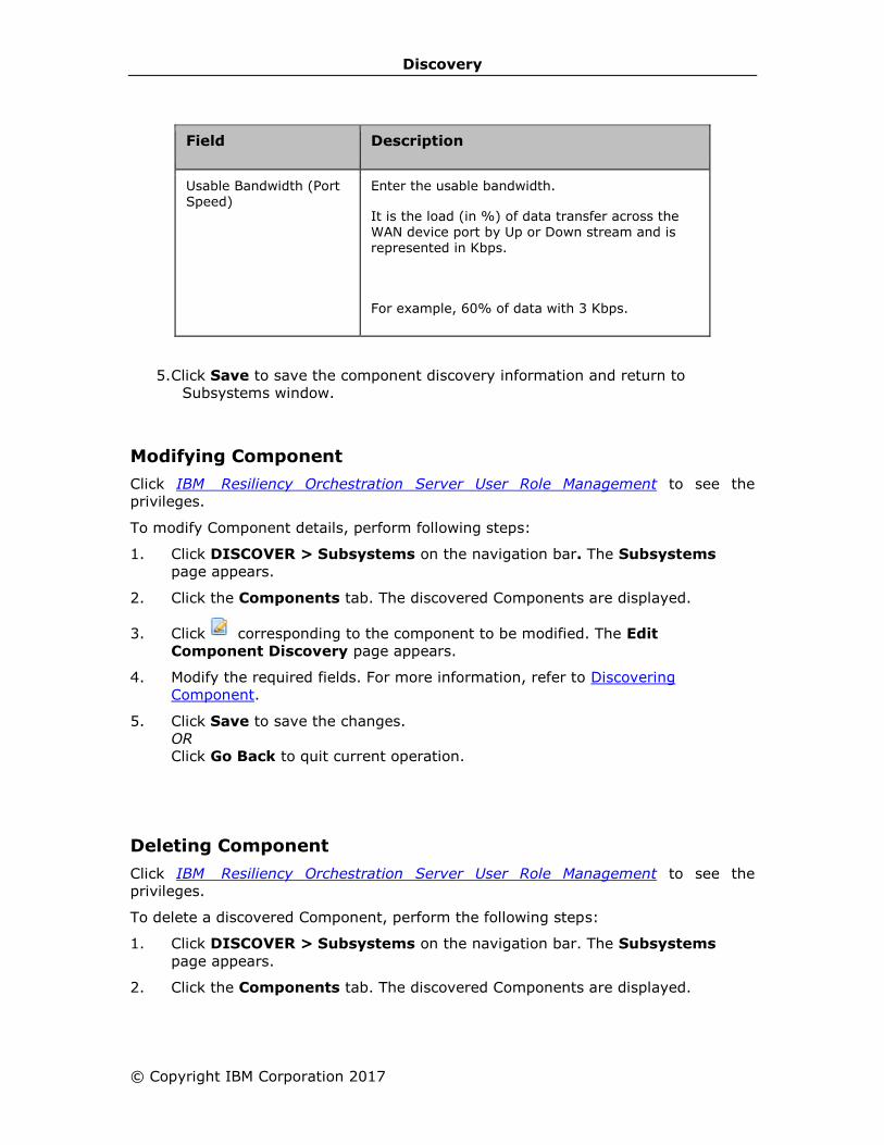
Discovery
© Copyright IBM Corporation 2017
Field Description
Usable Bandwidth (Port Speed)
Enter the usable bandwidth.
It is the load (in %) of data transfer across the WAN device port by Up or Down stream and is represented in Kbps.
For example, 60% of data with 3 Kbps.
5. Click Save to save the component discovery information and return to
Subsystems window.
Modifying Component
Click IBM Resiliency Orchestration Server User Role Management to see the
privileges.
To modify Component details, perform following steps:
1. Click DISCOVER > Subsystems on the navigation bar. The Subsystems
page appears.
2. Click the Components tab. The discovered Components are displayed.
3. Click corresponding to the component to be modified. The Edit
Component Discovery page appears.
4. Modify the required fields. For more information, refer to Discovering
Component.
5. Click Save to save the changes.
OR
Click Go Back to quit current operation.
Deleting Component
Click IBM Resiliency Orchestration Server User Role Management to see the
privileges.
To delete a discovered Component, perform the following steps:
1. Click DISCOVER > Subsystems on the navigation bar. The Subsystems
page appears.
2. Click the Components tab. The discovered Components are displayed.

IBM Resiliency Orchestration Administrator’s Guide
3. Click corresponding to the component to be deleted. A message box is
displayed confirming the deletion.
4. Click OK in the message box.
Datasets
Listing Datasets
The Datasets tab in the Subsystems page lists all the Datasets that have been
discovered.
Click IBM Resiliency Orchestration Server User Role Management to see the
privileges.
To view the discovered Datasets, perform following steps:
1. Click DISCOVER > Subsystems on the navigation bar. The Subsystems
page appears.
2. Click the Datasets tab.
Following table summarizes the information displayed on Datasets tab:
Field Description
Name Displays the Dataset name.
Type Displays the type of the discovered Dataset.
The available types are MS-SQL 2000, Oracle 9i, Sybase, and Application Sub System.
Site Displays the Site name to which the IBM Resiliency Orchestration Objects are connected.
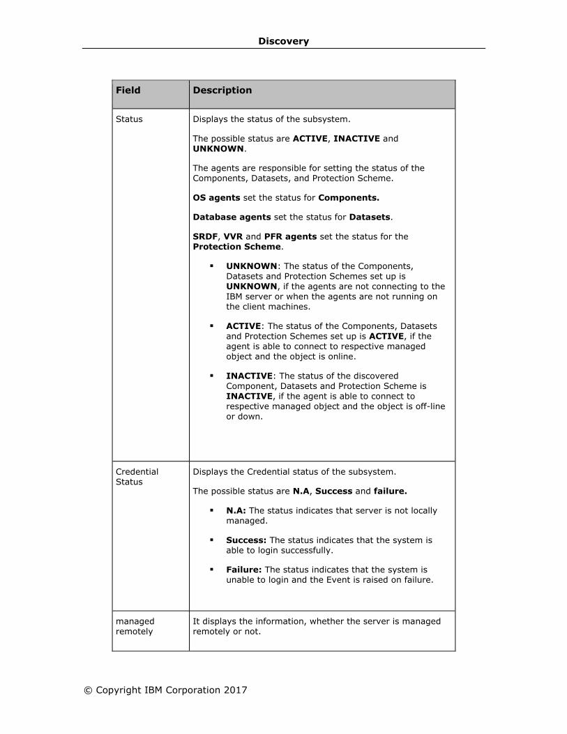
Discovery
© Copyright IBM Corporation 2017
Field Description
Status Displays the status of the subsystem.
The possible status are ACTIVE, INACTIVE and UNKNOWN.
The agents are responsible for setting the status of the Components, Datasets, and Protection Scheme.
OS agents set the status for Components.
Database agents set the status for Datasets.
SRDF, VVR and PFR agents set the status for the Protection Scheme.
▪ UNKNOWN: The status of the Components, Datasets and Protection Schemes set up is UNKNOWN, if the agents are not connecting to the IBM server or when the agents are not running on the client machines.
▪ ACTIVE: The status of the Components, Datasets and Protection Schemes set up is ACTIVE, if the agent is able to connect to respective managed object and the object is online.
▪ INACTIVE: The status of the discovered
Component, Datasets and Protection Scheme is INACTIVE, if the agent is able to connect to respective managed object and the object is off-line or down.
Credential Status
Displays the Credential status of the subsystem.
The possible status are N.A, Success and failure.
▪ N.A: The status indicates that server is not locally managed.
▪ Success: The status indicates that the system is able to login successfully.
▪ Failure: The status indicates that the system is unable to login and the Event is raised on failure.
managed remotely
It displays the information, whether the server is managed remotely or not.
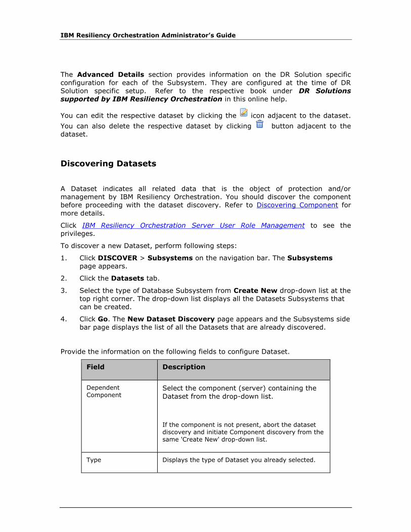
IBM Resiliency Orchestration Administrator’s Guide
The Advanced Details section provides information on the DR Solution specific
configuration for each of the Subsystem. They are configured at the time of DR
Solution specific setup. Refer to the respective book under DR Solutions
supported by IBM Resiliency Orchestration in this online help.
You can edit the respective dataset by clicking the icon adjacent to the dataset.
You can also delete the respective dataset by clicking button adjacent to the
dataset.
Discovering Datasets
A Dataset indicates all related data that is the object of protection and/or
management by IBM Resiliency Orchestration. You should discover the component
before proceeding with the dataset discovery. Refer to Discovering Component for
more details.
Click IBM Resiliency Orchestration Server User Role Management to see the
privileges.
To discover a new Dataset, perform following steps:
1. Click DISCOVER > Subsystems on the navigation bar. The Subsystems
page appears.
2. Click the Datasets tab.
3. Select the type of Database Subsystem from Create New drop-down list at the
top right corner. The drop-down list displays all the Datasets Subsystems that
can be created.
4. Click Go. The New Dataset Discovery page appears and the Subsystems side
bar page displays the list of all the Datasets that are already discovered.
Provide the information on the following fields to configure Dataset.
Field Description
Dependent
Component Select the component (server) containing the
Dataset from the drop-down list.
If the component is not present, abort the dataset discovery and initiate Component discovery from the same 'Create New' drop-down list.
Type Displays the type of Dataset you already selected.

Discovery
© Copyright IBM Corporation 2017
Field Description
You have the option to change your selection.
Dataset Name By default, the dataset name is auto populated which is a combination of dataset type and
component name.
OR
Enter a unique name for dataset.
Note:
This field only accepts alphanumeric characters and must start with an alphabetical character. It should not have a space.
Credentials This will be activated only on selecting the Server Managed Remotely check box. The following are the credentials available, select any one based on the requirement:
▪ Use Component Credentials: If the user wish to use the default credentials provided, select this option.
▪ Add New Credentials: Enter the UserName
and Password.
Note:
Port No (SSH) is fetched automatically, once the Dependent Component is selected.
▪ Other credentials are displayed which are created under Group credentials. Example: Unix, Linux or, Windows. It is in disabled mode and on selection of this option it is attached here.
Test Credentials Select Test Credentials button to validate the credentials entered. Appropriate message is shown,
if credential is success or failure.
5. Click Save to save the Dataset Discovery information and return to
Subsystems window.
For information related to DR Solution dataset:
Discovering MSSQL Dataset

IBM Resiliency Orchestration Administrator’s Guide
Discovering Oracle Dataset
Discovering Sybase Dataset
Discovering Application Subsystem Dataset
Discovering DB2 Dataset
Discovering PostgreSQL Dataset
Discovering MySQL Dataset
Discovering MS Exchange Dataset
Discovering MSSQL Dataset
IBM Resiliency Orchestration agent for MSSQL is designed to support multiple MSSQL
databases. Each MSSQL database to be protected by IBM Resiliency Orchestration
must be discovered as a separate dataset. The IBM Resiliency Orchestration agent
for MSSQL is configured per MSSQL instance which can have multiple databases
created on it. It takes the list of datasets discovered and monitors each one of
them.
Refer to Discovering Dataset to navigate and to configure the generic details for
discovering dataset.
Perform the following steps to configure the advanced details for the MSSQL dataset.
1. Enter the following information:
Field Description
Dependent Component
Select the component from the drop-down list
Type Select MSSQL from the drop-down list
Dataset Name Enter the dataset name
MSSQL Instance Details.
Database Name Provide the name of the pre-installed MSSQL
database. Click the Discover button, if the database
already exists. Auto Discovery will attempt to retrieve the Data File Name and Transactional Log File Name fields automatically.
Enter the details in the fields given below, if you want
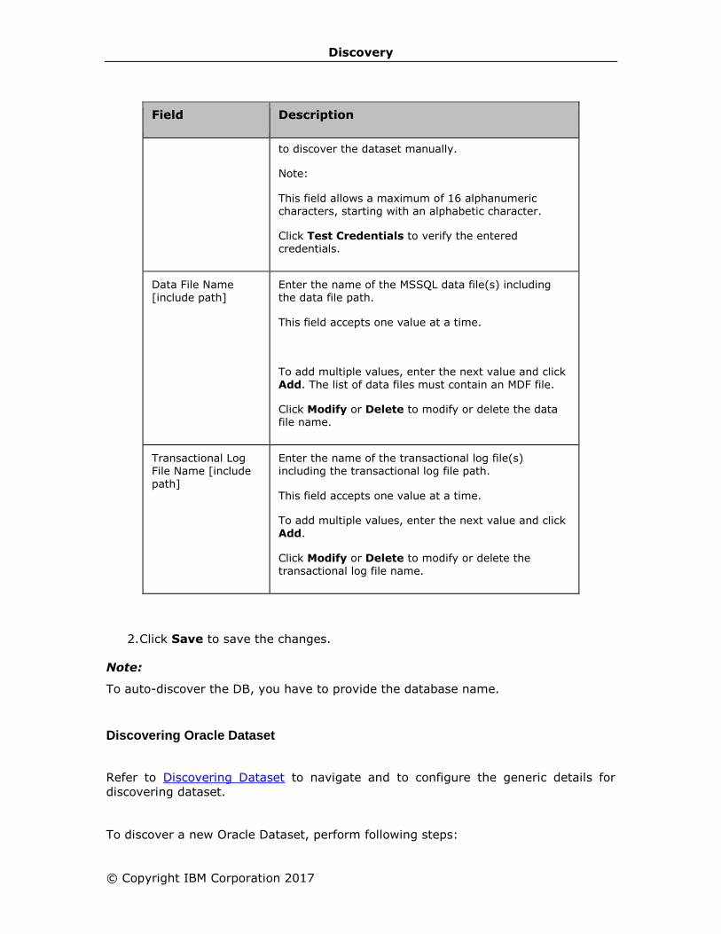
Discovery
© Copyright IBM Corporation 2017
Field Description
to discover the dataset manually.
Note:
This field allows a maximum of 16 alphanumeric characters, starting with an alphabetic character.
Click Test Credentials to verify the entered credentials.
Data File Name
[include path]
Enter the name of the MSSQL data file(s) including
the data file path.
This field accepts one value at a time.
To add multiple values, enter the next value and click Add. The list of data files must contain an MDF file.
Click Modify or Delete to modify or delete the data file name.
Transactional Log File Name [include path]
Enter the name of the transactional log file(s) including the transactional log file path.
This field accepts one value at a time.
To add multiple values, enter the next value and click Add.
Click Modify or Delete to modify or delete the transactional log file name.
2. Click Save to save the changes.
Note:
To auto-discover the DB, you have to provide the database name.
Discovering Oracle Dataset
Refer to Discovering Dataset to navigate and to configure the generic details for
discovering dataset.
To discover a new Oracle Dataset, perform following steps:
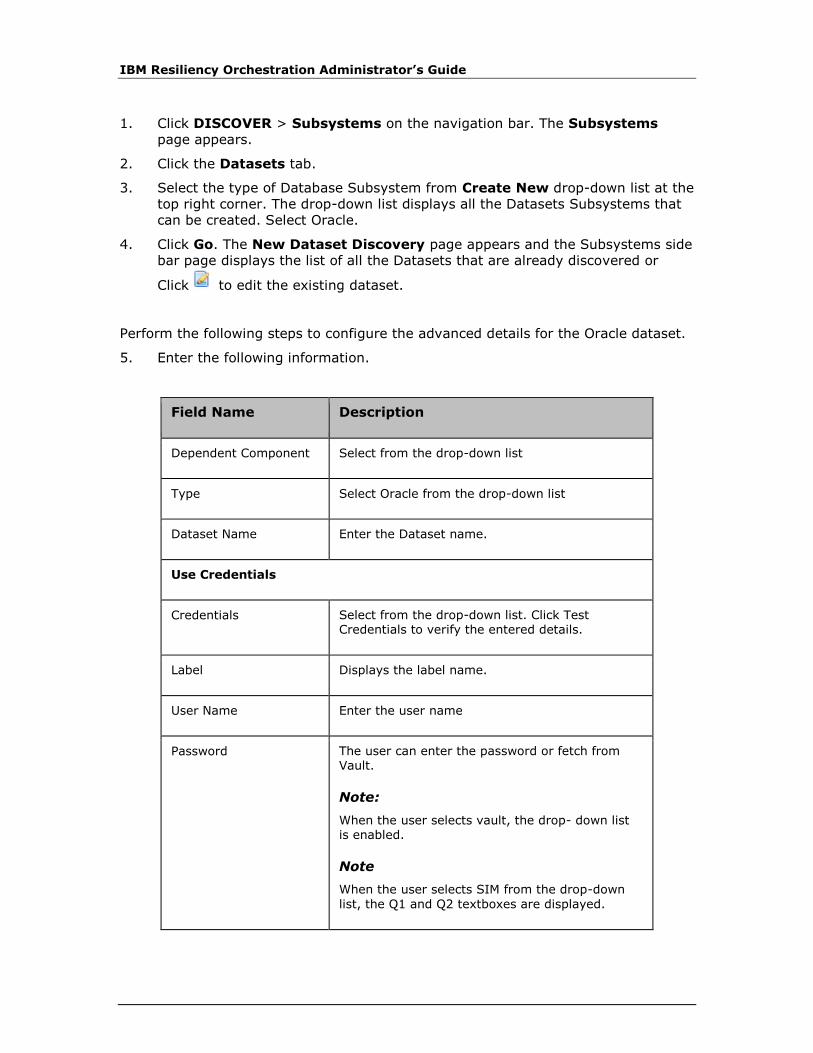
IBM Resiliency Orchestration Administrator’s Guide
1. Click DISCOVER > Subsystems on the navigation bar. The Subsystems
page appears.
2. Click the Datasets tab.
3. Select the type of Database Subsystem from Create New drop-down list at the
top right corner. The drop-down list displays all the Datasets Subsystems that
can be created. Select Oracle.
4. Click Go. The New Dataset Discovery page appears and the Subsystems side
bar page displays the list of all the Datasets that are already discovered or
Click to edit the existing dataset.
Perform the following steps to configure the advanced details for the Oracle dataset.
5. Enter the following information.
Field Name Description
Dependent Component Select from the drop-down list
Type Select Oracle from the drop-down list
Dataset Name Enter the Dataset name.
Use Credentials
Credentials Select from the drop-down list. Click Test Credentials to verify the entered details.
Label Displays the label name.
User Name Enter the user name
Password The user can enter the password or fetch from Vault.
Note:
When the user selects vault, the drop- down list is enabled.
Note
When the user selects SIM from the drop-down
list, the Q1 and Q2 textboxes are displayed.
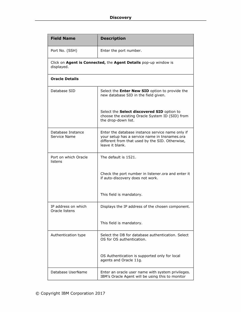
Discovery
© Copyright IBM Corporation 2017
Field Name Description
Port No. (SSH) Enter the port number.
Click on Agent is Connected, the Agent Details pop-up window is displayed.
Oracle Details
Database SID Select the Enter New SID option to provide the new database SID in the field given.
Select the Select discovered SID option to
choose the existing Oracle System ID (SID) from the drop-down list.
Database Instance Service Name
Enter the database instance service name only if your setup has a service name in tnsnames.ora different from that used by the SID. Otherwise, leave it blank.
Port on which Oracle listens
The default is 1521.
Check the port number in listener.ora and enter it if auto-discovery does not work.
This field is mandatory.
IP address on which Oracle listens
Displays the IP address of the chosen component.
This field is mandatory.
Authentication type Select the DB for database authentication. Select OS for OS authentication.
OS Authentication is supported only for local agents and Oracle 11g.
Database UserName Enter an oracle user name with system privileges. IBM’s Oracle Agent will be using this to monitor
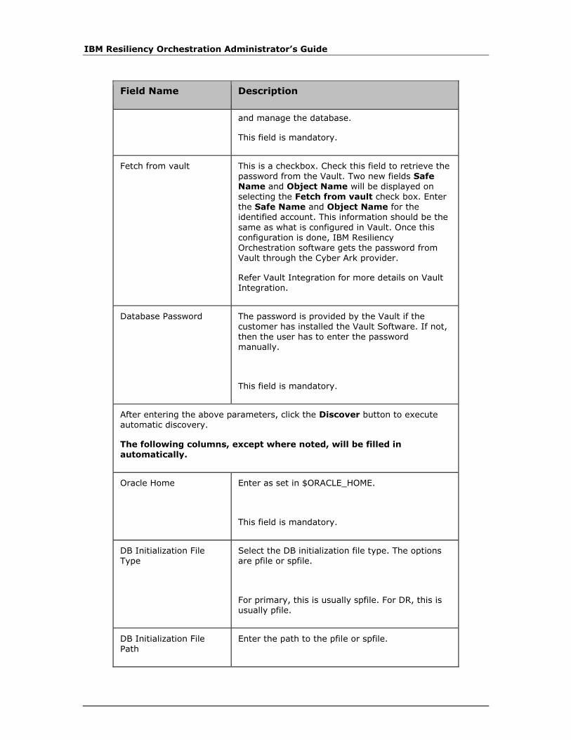
IBM Resiliency Orchestration Administrator’s Guide
Field Name Description
and manage the database.
This field is mandatory.
Fetch from vault This is a checkbox. Check this field to retrieve the password from the Vault. Two new fields Safe Name and Object Name will be displayed on selecting the Fetch from vault check box. Enter the Safe Name and Object Name for the identified account. This information should be the
same as what is configured in Vault. Once this
configuration is done, IBM Resiliency Orchestration software gets the password from Vault through the Cyber Ark provider.
Refer Vault Integration for more details on Vault Integration.
Database Password The password is provided by the Vault if the customer has installed the Vault Software. If not, then the user has to enter the password manually.
This field is mandatory.
After entering the above parameters, click the Discover button to execute automatic discovery.
The following columns, except where noted, will be filled in automatically.
Oracle Home Enter as set in $ORACLE_HOME.
This field is mandatory.
DB Initialization File Type
Select the DB initialization file type. The options are pfile or spfile.
For primary, this is usually spfile. For DR, this is usually pfile.
DB Initialization File Path
Enter the path to the pfile or spfile.

Discovery
© Copyright IBM Corporation 2017
Field Name Description
This field is mandatory.
DB Initialization File Name
Enter the name of the pfile or spfile.
This field is mandatory.
Data files Enter the database data files, separated by commas. From SQL > select name from v$datafile;
Redo logs Enter the database redo log files, separated by commas. From SQL > select member from
v$logfile;
Control files Enter the database control files, separated by commas. From SQL > select name from
v$controlfile;
Archivelogs location Enter the folder where Oracle dumps or applies
archive log files. From SQL > archive log list;
Standby Archivelogs location
Enter the alternate folder from which Oracle will look for archive log files to apply.
6. Click Save to save the changes.
Tip
Clicking the Agent is CONNECTED link displays Agent Details pop-up window.
When you scroll the Agent Details window in internet explorer using mouse wheel,
the background window also scrolls. To avoid this, use the scroll bar provided by the
Agents Details window.
Discovering Sybase Dataset
Refer to Discovering Dataset to navigate and to configure the generic details for
discovering dataset.
Perform the following steps to configure the advanced details for the Sybase dataset.
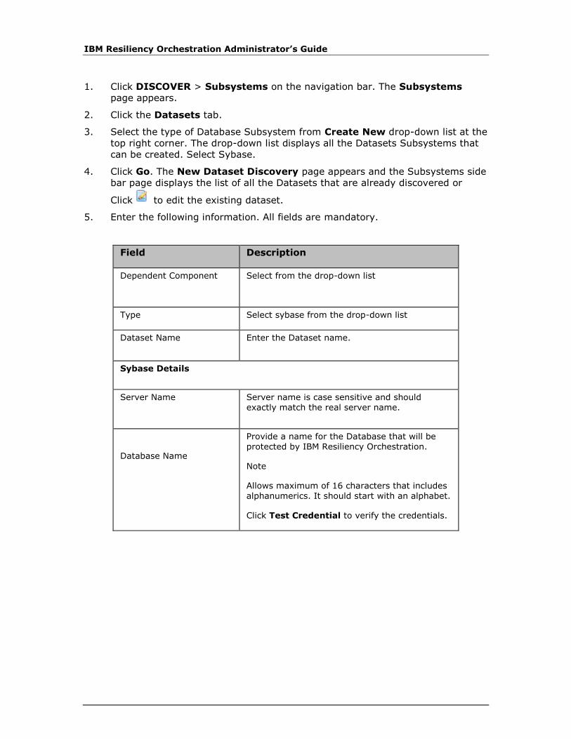
IBM Resiliency Orchestration Administrator’s Guide
1. Click DISCOVER > Subsystems on the navigation bar. The Subsystems
page appears.
2. Click the Datasets tab.
3. Select the type of Database Subsystem from Create New drop-down list at the
top right corner. The drop-down list displays all the Datasets Subsystems that
can be created. Select Sybase.
4. Click Go. The New Dataset Discovery page appears and the Subsystems side
bar page displays the list of all the Datasets that are already discovered or
Click to edit the existing dataset.
5. Enter the following information. All fields are mandatory.
Field Description
Dependent Component Select from the drop-down list
Type Select sybase from the drop-down list
Dataset Name Enter the Dataset name.
Sybase Details
Server Name Server name is case sensitive and should exactly match the real server name.
Database Name
Provide a name for the Database that will be protected by IBM Resiliency Orchestration.
Note
Allows maximum of 16 characters that includes alphanumerics. It should start with an alphabet.
Click Test Credential to verify the credentials.
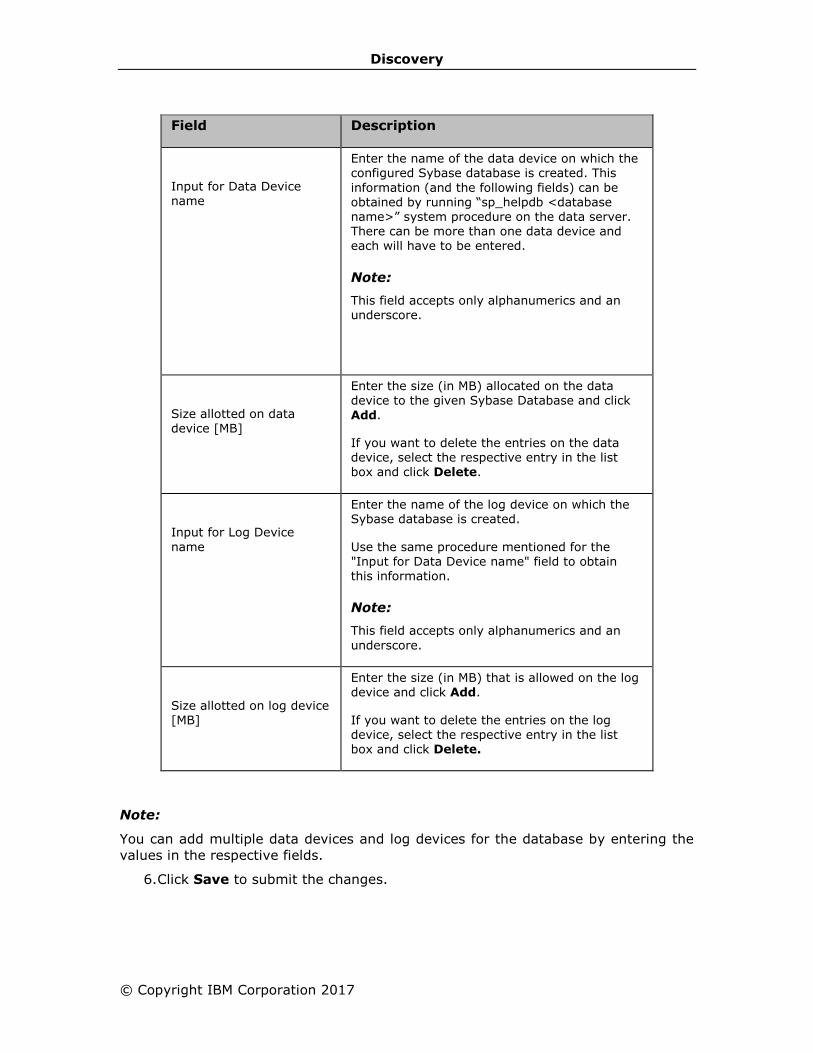
Discovery
© Copyright IBM Corporation 2017
Field Description
Input for Data Device name
Enter the name of the data device on which the configured Sybase database is created. This
information (and the following fields) can be obtained by running “sp_helpdb <database name>” system procedure on the data server. There can be more than one data device and each will have to be entered.
Note:
This field accepts only alphanumerics and an underscore.
Size allotted on data device [MB]
Enter the size (in MB) allocated on the data device to the given Sybase Database and click
Add.
If you want to delete the entries on the data device, select the respective entry in the list box and click Delete.
Input for Log Device
name
Enter the name of the log device on which the Sybase database is created.
Use the same procedure mentioned for the
"Input for Data Device name" field to obtain this information.
Note:
This field accepts only alphanumerics and an
underscore.
Size allotted on log device [MB]
Enter the size (in MB) that is allowed on the log device and click Add.
If you want to delete the entries on the log device, select the respective entry in the list box and click Delete.
Note:
You can add multiple data devices and log devices for the database by entering the
values in the respective fields.
6. Click Save to submit the changes.
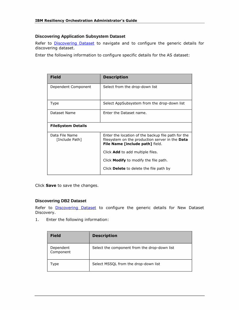
IBM Resiliency Orchestration Administrator’s Guide
Discovering Application Subsystem Dataset
Refer to Discovering Dataset to navigate and to configure the generic details for
discovering dataset.
Enter the following information to configure specific details for the AS dataset:
Field Description
Dependent Component Select from the drop-down list
Type Select AppSubsystem from the drop-down list
Dataset Name Enter the Dataset name.
FileSystem Details
Data File Name [Include Path]
Enter the location of the backup file path for the filesystem on the production server in the Data File Name [include path] field.
Click Add to add multiple files.
Click Modify to modify the file path.
Click Delete to delete the file path by
Click Save to save the changes.
Discovering DB2 Dataset
Refer to Discovering Dataset to configure the generic details for New Dataset
Discovery.
1. Enter the following information:
Field Description
Dependent Component
Select the component from the drop-down list
Type Select MSSQL from the drop-down list
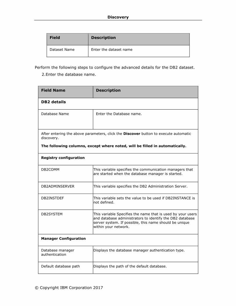
Discovery
© Copyright IBM Corporation 2017
Field Description
Dataset Name Enter the dataset name
Perform the following steps to configure the advanced details for the DB2 dataset.
2. Enter the database name.
Field Name Description
DB2 details
Database Name
Enter the Database name.
After entering the above parameters, click the Discover button to execute automatic discovery.
The following columns, except where noted, will be filled in automatically.
Registry configuration
DB2COMM This variable specifies the communication managers that are started when the database manager is started.
DB2ADMINSERVER This variable specifies the DB2 Administration Server.
DB2INSTDEF This variable sets the value to be used if DB2INSTANCE is not defined.
DB2SYSTEM This variable Specifies the name that is used by your users and database administrators to identify the DB2 database
server system. If possible, this name should be unique
within your network.
Manager Configuration
Database manager authentication
Displays the database manager authentication type.
Default database path Displays the path of the default database.
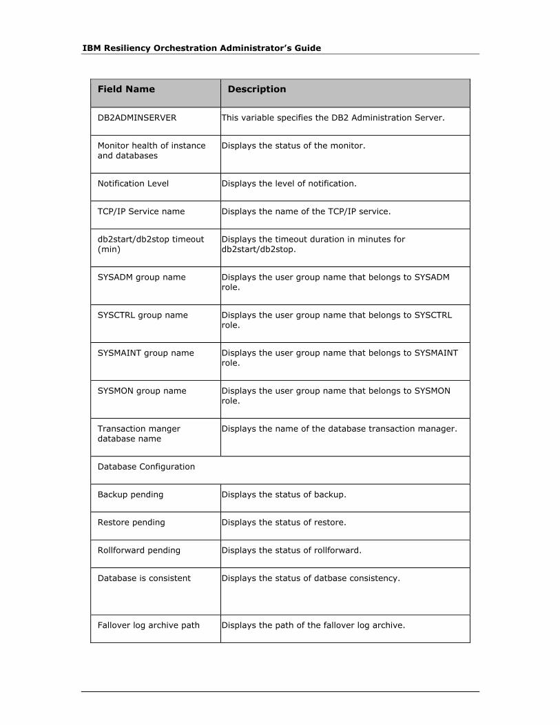
IBM Resiliency Orchestration Administrator’s Guide
Field Name Description
DB2ADMINSERVER This variable specifies the DB2 Administration Server.
Monitor health of instance and databases
Displays the status of the monitor.
Notification Level Displays the level of notification.
TCP/IP Service name Displays the name of the TCP/IP service.
db2start/db2stop timeout (min)
Displays the timeout duration in minutes for db2start/db2stop.
SYSADM group name Displays the user group name that belongs to SYSADM role.
SYSCTRL group name Displays the user group name that belongs to SYSCTRL role.
SYSMAINT group name Displays the user group name that belongs to SYSMAINT role.
SYSMON group name Displays the user group name that belongs to SYSMON role.
Transaction manger database name
Displays the name of the database transaction manager.
Database Configuration
Backup pending Displays the status of backup.
Restore pending Displays the status of restore.
Rollforward pending Displays the status of rollforward.
Database is consistent Displays the status of datbase consistency.
Fallover log archive path Displays the path of the fallover log archive.

Discovery
© Copyright IBM Corporation 2017
Field Name Description
Mirror log path Displays the path of the mirror log.
New log path Displays the path of the new log.
Path to log files Displays the path to log files.
Overflow log path Displays the path of the overflow log.
First log archive method Displays the status and method of first log archive.
Second log archive method Displays the status and method of second log archive.
Option for logarchmeth1 Displays the option for the method of first log archive.
Option for logarchmeth2 Displays the option for the method of second log archive.
log file size Displays the size of log file.
Number of primary log files Displays the numerical quantity of primary log files.
Number of secondary log files
Displays the numerical quantity of secondary log files.
Log retain for recovery status
Displays the status of the log retain for recovery.
User exit for logging status Displays the status of the user exit for logging.
Note:
Few fields mentioned in the above table does not display any value. This is limitation
in DB2 version 9.7 with Linux and Windows Operating System.
3. Click Save to save the changes.
Note:
Clicking the Agent is CONNECTED link displays Agent Details pop-up window.
When you scroll the Agent Details window in internet explorer using mouse wheel,
the background window also scrolls. To avoid this, use the scroll bar provided by the
Agents Details window.

IBM Resiliency Orchestration Administrator’s Guide
Discovering PostgreSQL Dataset
Refer to Discovering Dataset to navigate and to configure the generic details for
discovering dataset.
PostgreSQL dataset discovery involves discovering the cluster data directory and the
details of the database. Multiple PostgreSQL cluster instances on the same server is
also supported.
Before discovering the dataset, PostgreSQL agent should be configured with the
following parameters by the user. The same agent can be configured to connect to
all the cluster instances running on that particular component.
Enter the following fields to discover a new dataset
Field Description
Dependent Component Select the component from the drop-down list
Type Select Oracle from the drop-down list
Dataset Name Enter the Dataset name.
1. Enter the following information.
Field Name Description
PostgreSQL Home The directory where PostgreSQL is installed
PostgreSQL Data The cluster data directory
Host IP The IP address on which the PostgreSQL is listening and the clients can connect
Host Port The port on which the PostgreSQL is listening and the clients can connect
User Name The user name using which the agent should connect
Password The password for the user
2. To configure a new cluster instance, select Add New from the drop down list
and specifying the data directory.
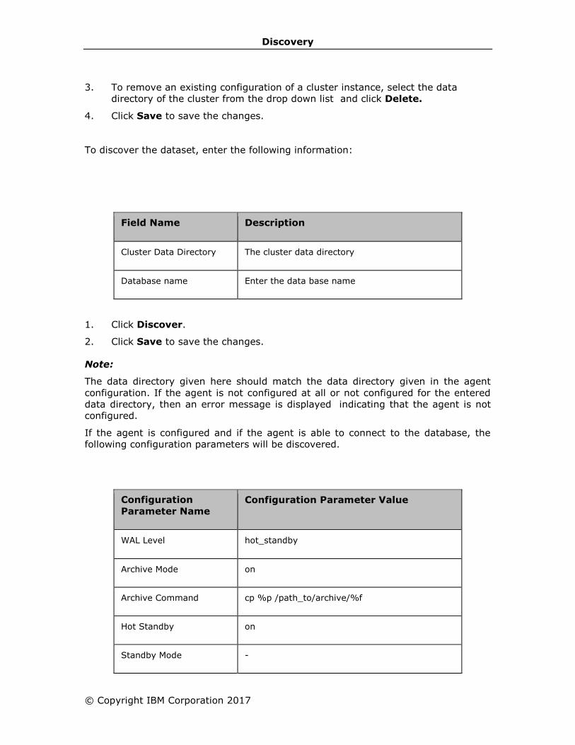
Discovery
© Copyright IBM Corporation 2017
3. To remove an existing configuration of a cluster instance, select the data
directory of the cluster from the drop down list and click Delete.
4. Click Save to save the changes.
To discover the dataset, enter the following information:
Field Name Description
Cluster Data Directory The cluster data directory
Database name Enter the data base name
1. Click Discover.
2. Click Save to save the changes.
Note:
The data directory given here should match the data directory given in the agent
configuration. If the agent is not configured at all or not configured for the entered
data directory, then an error message is displayed indicating that the agent is not
configured.
If the agent is configured and if the agent is able to connect to the database, the
following configuration parameters will be discovered.
Configuration
Parameter Name
Configuration Parameter Value
WAL Level hot_standby
Archive Mode on
Archive Command cp %p /path_to/archive/%f
Hot Standby on
Standby Mode -
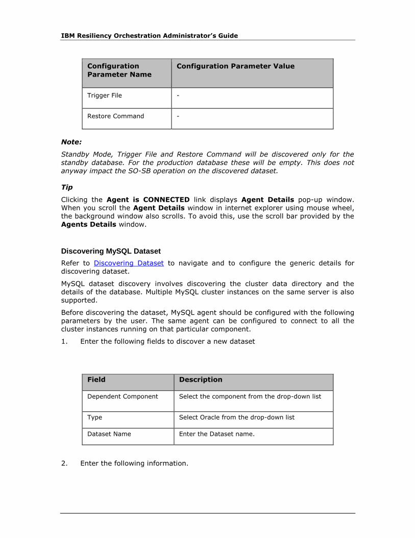
IBM Resiliency Orchestration Administrator’s Guide
Configuration
Parameter Name
Configuration Parameter Value
Trigger File -
Restore Command -
Note:
Standby Mode, Trigger File and Restore Command will be discovered only for the
standby database. For the production database these will be empty. This does not
anyway impact the SO-SB operation on the discovered dataset.
Tip
Clicking the Agent is CONNECTED link displays Agent Details pop-up window.
When you scroll the Agent Details window in internet explorer using mouse wheel,
the background window also scrolls. To avoid this, use the scroll bar provided by the
Agents Details window.
Discovering MySQL Dataset
Refer to Discovering Dataset to navigate and to configure the generic details for
discovering dataset.
MySQL dataset discovery involves discovering the cluster data directory and the
details of the database. Multiple MySQL cluster instances on the same server is also
supported.
Before discovering the dataset, MySQL agent should be configured with the following
parameters by the user. The same agent can be configured to connect to all the
cluster instances running on that particular component.
1. Enter the following fields to discover a new dataset
Field Description
Dependent Component Select the component from the drop-down list
Type Select Oracle from the drop-down list
Dataset Name Enter the Dataset name.
2. Enter the following information.
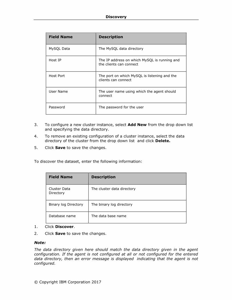
Discovery
© Copyright IBM Corporation 2017
Field Name Description
MySQL Data The MySQL data directory
Host IP The IP address on which MySQL is running and the clients can connect
Host Port The port on which MySQL is listening and the clients can connect
User Name The user name using which the agent should
connect
Password The password for the user
3. To configure a new cluster instance, select Add New from the drop down list
and specifying the data directory.
4. To remove an existing configuration of a cluster instance, select the data
directory of the cluster from the drop down list and click Delete.
5. Click Save to save the changes.
To discover the dataset, enter the following information:
Field Name Description
Cluster Data Directory
The cluster data directory
Binary log Directory The binary log directory
Database name The data base name
1. Click Discover.
2. Click Save to save the changes.
Note:
The data directory given here should match the data directory given in the agent
configuration. If the agent is not configured at all or not configured for the entered
data directory, then an error message is displayed indicating that the agent is not
configured.
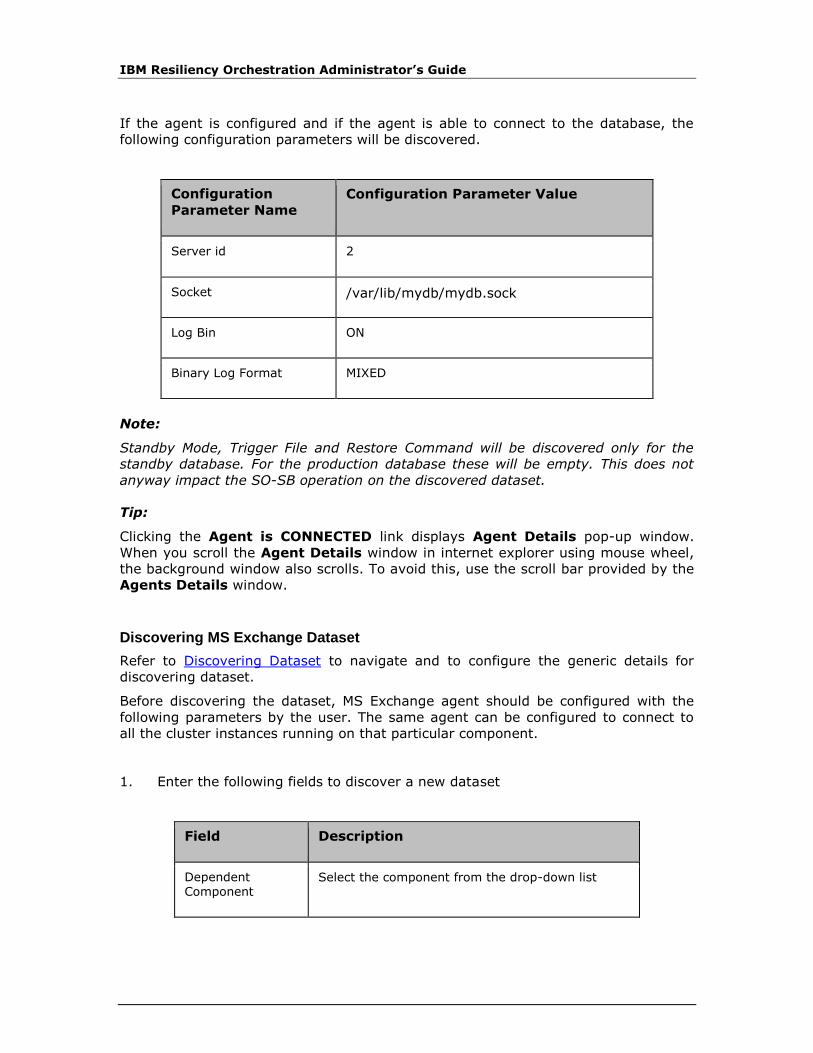
IBM Resiliency Orchestration Administrator’s Guide
If the agent is configured and if the agent is able to connect to the database, the
following configuration parameters will be discovered.
Configuration
Parameter Name
Configuration Parameter Value
Server id 2
Socket /var/lib/mydb/mydb.sock
Log Bin ON
Binary Log Format MIXED
Note:
Standby Mode, Trigger File and Restore Command will be discovered only for the
standby database. For the production database these will be empty. This does not
anyway impact the SO-SB operation on the discovered dataset.
Tip:
Clicking the Agent is CONNECTED link displays Agent Details pop-up window.
When you scroll the Agent Details window in internet explorer using mouse wheel,
the background window also scrolls. To avoid this, use the scroll bar provided by the
Agents Details window.
Discovering MS Exchange Dataset
Refer to Discovering Dataset to navigate and to configure the generic details for
discovering dataset.
Before discovering the dataset, MS Exchange agent should be configured with the
following parameters by the user. The same agent can be configured to connect to
all the cluster instances running on that particular component.
1. Enter the following fields to discover a new dataset
Field Description
Dependent Component
Select the component from the drop-down list

Discovery
© Copyright IBM Corporation 2017
Field Description
Type Select Oracle from the drop-down list
Dataset Name Enter the Dataset name.
2. Enter the following information.
Field Description
Host Name Name of the host.
Install Path Path where IBM Resiliency Orchestration scripts for MS-Exchange are installed.
3. Click Save to save the changes.
4. Click Close to close the pop-up.
To discover the dataset
1. Click Get DB to display the drop-down list of Database names.
2. Select the Database name from the available list.
Field Name Description
Database Name Name of the Database.
3. Click Discover.
4. Click Save to save the changes.
Note:
The data directory given here should match the data directory given in the agent
configuration. If the agent is not configured at all or not configured for the entered
data directory, then an error message is displayed indicating that the agent is not
configured.
If the agent is configured and if the agent is able to connect to the database, the
following configuration parameters will be discovered.

IBM Resiliency Orchestration Administrator’s Guide
Configuration
Parameter Name
Configuration Parameter Value
Name Mailbox DR
Server EXCHDR
AdministrativeGroup Exchange Administrative Group FYDIBOHF23SPDLT
DatabaseCreated True
Description
DatabaseCopies Mailbox DR\EXCHDR Mailbox DR\EXCHPR Mailbox DR\EXCHDR 25
Servers EXCHDR EXCHPR EXCHDR25
ReplayLagTimes EXCHDR, 00:00:00 EXCHPR, 00:00:00 EXCHDR25, 00:00:00
TruncationLagTimes EXCHDR, 00:00:00 EXCHPR, 00:00:00 EXCHDR25,
00:00:00
LogFilePrefix E00
LogFileSize 1024
IsPublicFolderDatabase False
ExchangeVersion 0.10 14.0.100.0
WhenCreated 01112012 20:33:59
Tip:
Clicking the Agent is CONNECTED link displays Agent Details pop-up window.
When you scroll the Agent Details window in internet explorer using mouse wheel,
the background window also scrolls. To avoid this, use the scroll bar provided by the
Agents Details window.
Discovery
© Copyright IBM Corporation 2017
Modifying Dataset
Click IBM Resiliency Orchestration Server User Role Management to see the
privileges.
To modify Datasets, perform following steps:
1. Click DISCOVER > Subsystems on the navigation bar. The Subsystems
page appears.
2. Click the Datasets tab. The discovered Datasets are displayed.
3. Click corresponding to the dataset to be modified. The Dataset Discovery
page appears.
4. Modify the required fields. For more information, refer to Discovering Dataset.
5. Click Save to save the changes.
OR
Click Go Back to quit current operation.
Cloning a Dataset
Click IBM Resiliency Orchestration Server User Role Management to see the
privileges.
Note:
The cloning of Datasets is supported for the following databases:
• Oracle
• MSSQL
• DB2
To clone a Dataset, perform following steps:
1. Click DISCOVER > Subsystems on the navigation bar. The Subsystems page
appears.
2. Click the Datasets tab. The discovered Datasets are displayed.
3. Click the Clone icon corresponding to the dataset to be cloned. The selected
Dataset is cloned and a message displayed.
The cloned Dataset is an exact duplicate of the selected Dataset.
4. You can modify the cloned Dataset, if required. For more information, refer to
Discovering Dataset.
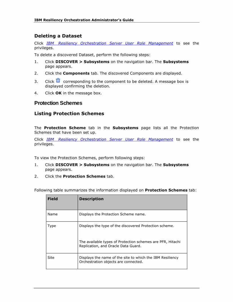
IBM Resiliency Orchestration Administrator’s Guide
Deleting a Dataset
Click IBM Resiliency Orchestration Server User Role Management to see the
privileges.
To delete a discovered Dataset, perform the following steps:
1. Click DISCOVER > Subsystems on the navigation bar. The Subsystems
page appears.
2. Click the Components tab. The discovered Components are displayed.
3. Click corresponding to the component to be deleted. A message box is
displayed confirming the deletion.
4. Click OK in the message box.
Protection Schemes
Listing Protection Schemes
The Protection Scheme tab in the Subsystems page lists all the Protection
Schemes that have been set up.
Click IBM Resiliency Orchestration Server User Role Management to see the
privileges.
To view the Protection Schemes, perform following steps:
1. Click DISCOVER > Subsystems on the navigation bar. The Subsystems
page appears.
2. Click the Protection Schemes tab.
Following table summarizes the information displayed on Protection Schemes tab:
Field Description
Name Displays the Protection Scheme name.
Type Displays the type of the discovered Protection scheme.
The available types of Protection schemes are PFR, Hitachi Replication, and Oracle Data Guard.
Site Displays the name of the site to which the IBM Resiliency Orchestration objects are connected.
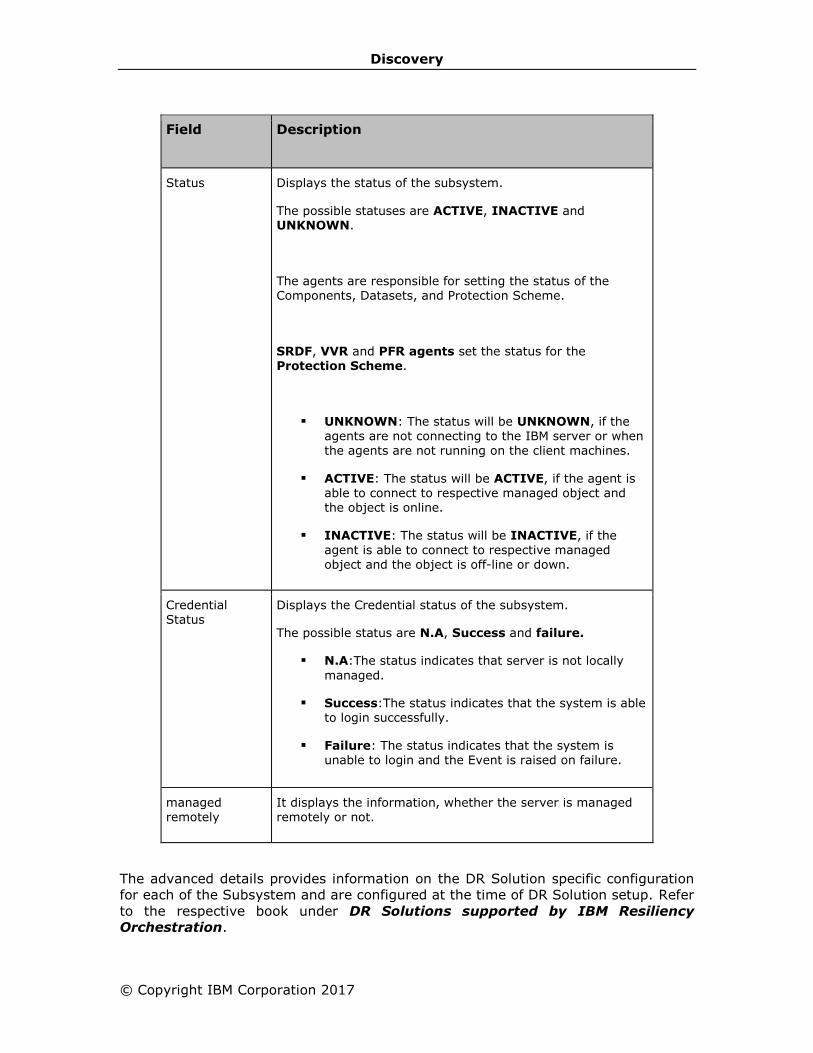
Discovery
© Copyright IBM Corporation 2017
Field Description
Status Displays the status of the subsystem.
The possible statuses are ACTIVE, INACTIVE and UNKNOWN.
The agents are responsible for setting the status of the Components, Datasets, and Protection Scheme.
SRDF, VVR and PFR agents set the status for the Protection Scheme.
▪ UNKNOWN: The status will be UNKNOWN, if the agents are not connecting to the IBM server or when the agents are not running on the client machines.
▪ ACTIVE: The status will be ACTIVE, if the agent is able to connect to respective managed object and the object is online.
▪ INACTIVE: The status will be INACTIVE, if the agent is able to connect to respective managed
object and the object is off-line or down.
Credential Status
Displays the Credential status of the subsystem.
The possible status are N.A, Success and failure.
▪ N.A:The status indicates that server is not locally
managed.
▪ Success:The status indicates that the system is able to login successfully.
▪ Failure: The status indicates that the system is unable to login and the Event is raised on failure.
managed remotely
It displays the information, whether the server is managed remotely or not.
The advanced details provides information on the DR Solution specific configuration
for each of the Subsystem and are configured at the time of DR Solution setup. Refer
to the respective book under DR Solutions supported by IBM Resiliency
Orchestration.
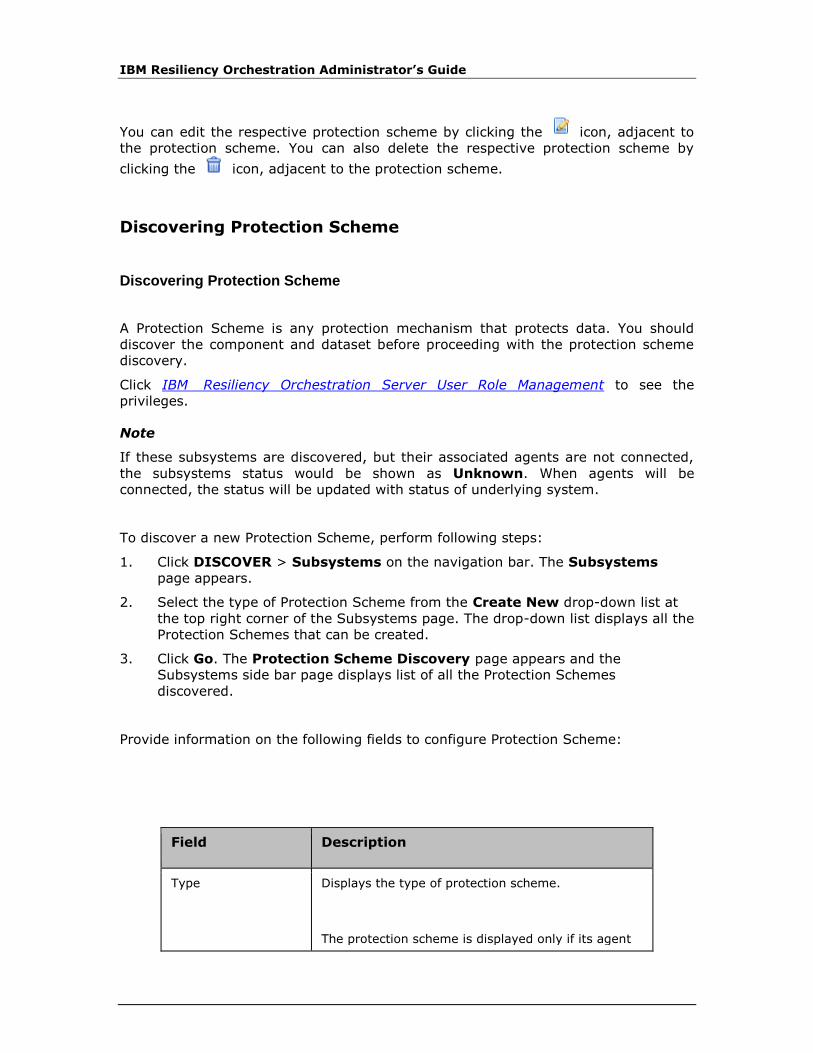
IBM Resiliency Orchestration Administrator’s Guide
You can edit the respective protection scheme by clicking the icon, adjacent to
the protection scheme. You can also delete the respective protection scheme by
clicking the icon, adjacent to the protection scheme.
Discovering Protection Scheme
Discovering Protection Scheme
A Protection Scheme is any protection mechanism that protects data. You should
discover the component and dataset before proceeding with the protection scheme
discovery.
Click IBM Resiliency Orchestration Server User Role Management to see the
privileges.
Note
If these subsystems are discovered, but their associated agents are not connected,
the subsystems status would be shown as Unknown. When agents will be
connected, the status will be updated with status of underlying system.
To discover a new Protection Scheme, perform following steps:
1. Click DISCOVER > Subsystems on the navigation bar. The Subsystems
page appears.
2. Select the type of Protection Scheme from the Create New drop-down list at
the top right corner of the Subsystems page. The drop-down list displays all the
Protection Schemes that can be created.
3. Click Go. The Protection Scheme Discovery page appears and the
Subsystems side bar page displays list of all the Protection Schemes
discovered.
Provide information on the following fields to configure Protection Scheme:
Field Description
Type Displays the type of protection scheme.
The protection scheme is displayed only if its agent

Discovery
© Copyright IBM Corporation 2017
Field Description
is connected to the IBM Resiliency Orchestration server. This is applicable for all protection schemes except for the one that requires manual discovery.
Name
Enter a unique name for protection scheme.
This field accepts alphanumeric characters, and underscores and the name must start with an alphabet. It should not have a space.
This field is mandatory.
Management Host Select DR Solution specific Component from the drop-down list to be associated to the protection scheme.
If no components are present, abort Protection Scheme discovery and initiate Component discovery.
Credentials This will be activated only on selecting the Server Managed Remotely check box. The following are the credentials available, select any one based on the requirement:
▪ Use Component Credentials: If the user
wish to use the default credentials provided, select this option.
▪ Add New Credentials: Enter the UserName and Password.
Note
Port No (SSH) is fetched automatically, once the Dependent Component is selected.
▪ Other credentials are displayed which are created under Group credentials. Example: Unix, Linux or, Windows. It is in disabled mode and on selection of this option it is
attached here.
Test Credentials Select Test Credentials button to validate the credentials entered. Appropriate message is shown,
if credential is success or failure.
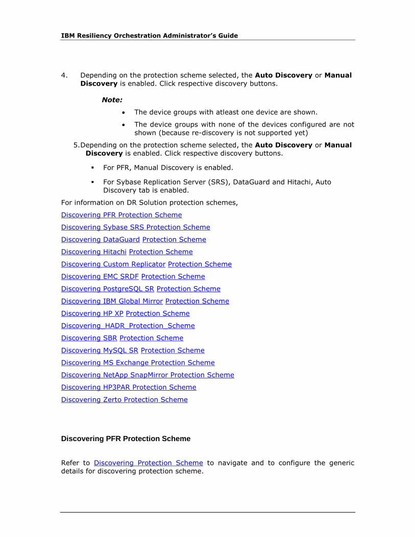
IBM Resiliency Orchestration Administrator’s Guide
4. Depending on the protection scheme selected, the Auto Discovery or Manual
Discovery is enabled. Click respective discovery buttons.
Note:
• The device groups with atleast one device are shown.
• The device groups with none of the devices configured are not
shown (because re-discovery is not supported yet)
5. Depending on the protection scheme selected, the Auto Discovery or Manual
Discovery is enabled. Click respective discovery buttons.
▪ For PFR, Manual Discovery is enabled.
▪ For Sybase Replication Server (SRS), DataGuard and Hitachi, Auto
Discovery tab is enabled.
For information on DR Solution protection schemes,
Discovering PFR Protection Scheme
Discovering Sybase SRS Protection Scheme
Discovering DataGuard Protection Scheme
Discovering Hitachi Protection Scheme
Discovering Custom Replicator Protection Scheme
Discovering EMC SRDF Protection Scheme
Discovering PostgreSQL SR Protection Scheme
Discovering IBM Global Mirror Protection Scheme
Discovering HP XP Protection Scheme
Discovering_HADR_Protection_Scheme
Discovering SBR Protection Scheme
Discovering MySQL SR Protection Scheme
Discovering MS Exchange Protection Scheme
Discovering NetApp SnapMirror Protection Scheme
Discovering HP3PAR Protection Scheme
Discovering Zerto Protection Scheme
Discovering PFR Protection Scheme
Refer to Discovering Protection Scheme to navigate and to configure the generic
details for discovering protection scheme.
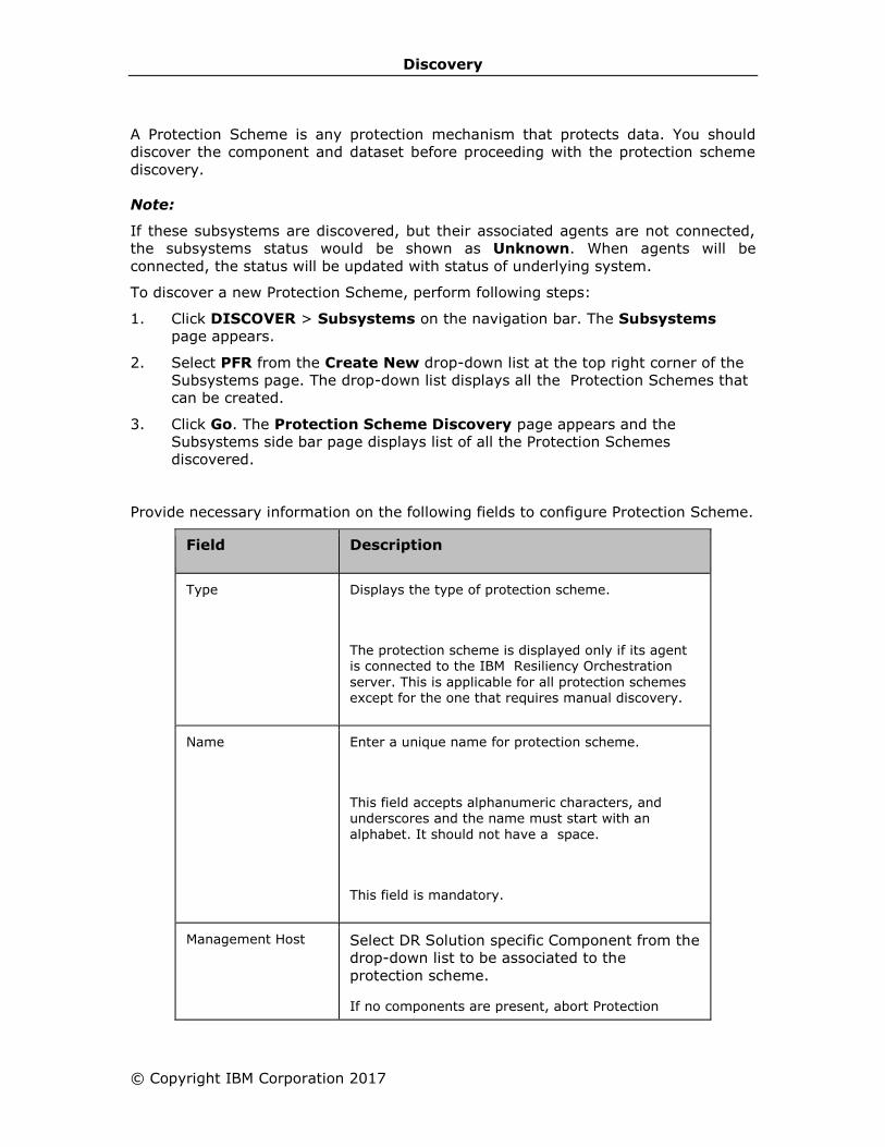
Discovery
© Copyright IBM Corporation 2017
A Protection Scheme is any protection mechanism that protects data. You should
discover the component and dataset before proceeding with the protection scheme
discovery.
Note:
If these subsystems are discovered, but their associated agents are not connected,
the subsystems status would be shown as Unknown. When agents will be
connected, the status will be updated with status of underlying system.
To discover a new Protection Scheme, perform following steps:
1. Click DISCOVER > Subsystems on the navigation bar. The Subsystems
page appears.
2. Select PFR from the Create New drop-down list at the top right corner of the
Subsystems page. The drop-down list displays all the Protection Schemes that
can be created.
3. Click Go. The Protection Scheme Discovery page appears and the
Subsystems side bar page displays list of all the Protection Schemes
discovered.
Provide necessary information on the following fields to configure Protection Scheme.
Field Description
Type Displays the type of protection scheme.
The protection scheme is displayed only if its agent is connected to the IBM Resiliency Orchestration
server. This is applicable for all protection schemes except for the one that requires manual discovery.
Name
Enter a unique name for protection scheme.
This field accepts alphanumeric characters, and underscores and the name must start with an
alphabet. It should not have a space.
This field is mandatory.
Management Host Select DR Solution specific Component from the
drop-down list to be associated to the
protection scheme.
If no components are present, abort Protection

IBM Resiliency Orchestration Administrator’s Guide
Field Description
Scheme discovery and initiate Component discovery.
Fileset Name If Fileset Name is provided then it should start with an alphabet, can contain alpha numeric, underscore
and maximum of 64 characters.
Fileset Name is auto-generated (if not provided) during group creation).
4. Click Save to save the entered details to complete protection scheme setup.
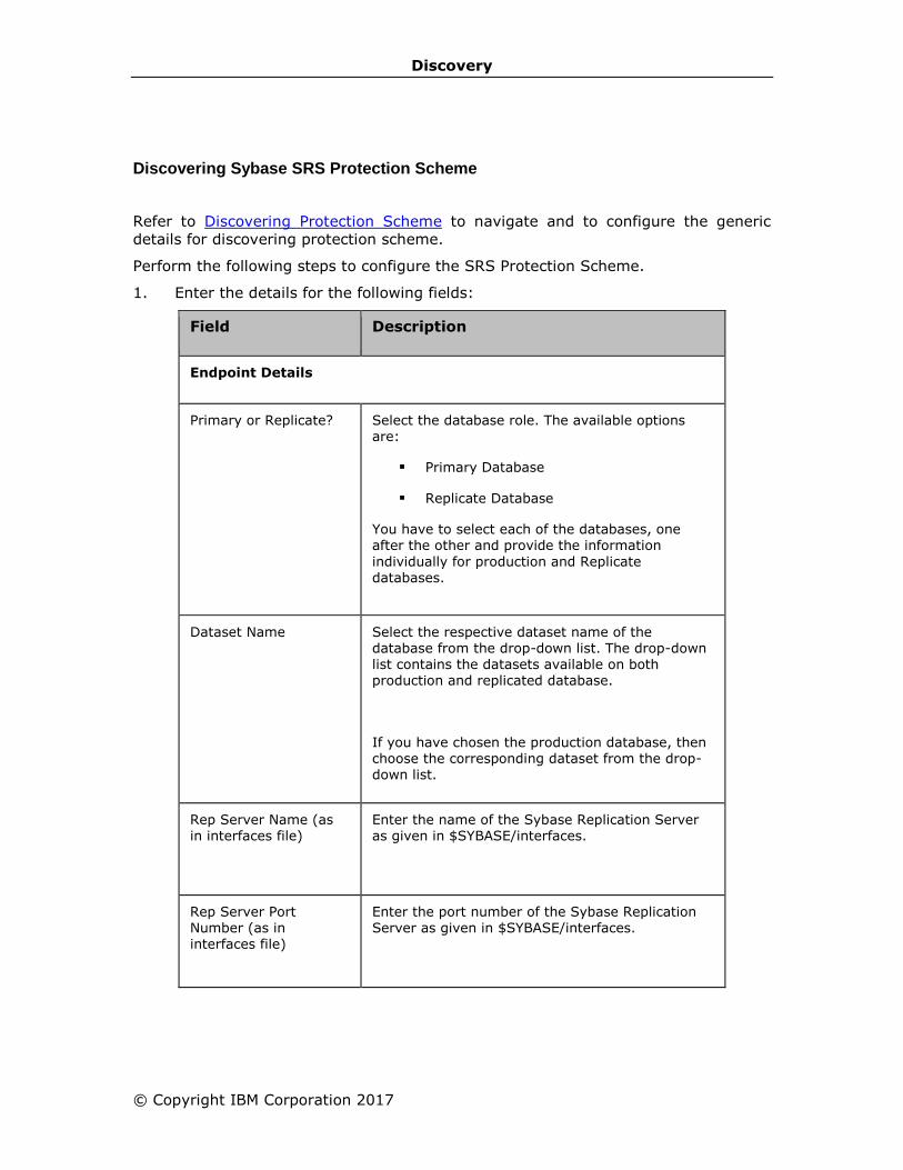
Discovery
© Copyright IBM Corporation 2017
Discovering Sybase SRS Protection Scheme
Refer to Discovering Protection Scheme to navigate and to configure the generic
details for discovering protection scheme.
Perform the following steps to configure the SRS Protection Scheme.
1. Enter the details for the following fields:
Field Description
Endpoint Details
Primary or Replicate?
Select the database role. The available options are:
▪ Primary Database
▪ Replicate Database
You have to select each of the databases, one after the other and provide the information
individually for production and Replicate databases.
Dataset Name
Select the respective dataset name of the database from the drop-down list. The drop-down list contains the datasets available on both production and replicated database.
If you have chosen the production database, then choose the corresponding dataset from the drop-down list.
Rep Server Name (as in interfaces file)
Enter the name of the Sybase Replication Server as given in $SYBASE/interfaces.
Rep Server Port Number (as in interfaces file)
Enter the port number of the Sybase Replication Server as given in $SYBASE/interfaces.

IBM Resiliency Orchestration Administrator’s Guide
Field Description
Replication Server Credentials
Provide the following login details for SRS.
▪ User Name - Provide the system administrator login name. By default, it is "sa"
▪ Password - Provide the system
administrator password.
▪ Password (confirm) - Re-type the password to confirm.
RSSD Credentials
Provide the following login details for RSSD. If the login details are the same as the Replication Server, then enable the Same as Replication Server check box.
2. Perform any of the following:
▪ Click Reset to re-enter the values.
▪ Click Discover to discover the SRS protection scheme.
Discovering DataGuard Protection Scheme
Refer to Discovering Protection Scheme to navigate and to configure the generic
details for discovering protection scheme.
Perform the following steps to configure the advanced details for the DataGuard
protection scheme.
1. Enter the details for the following fields:
Field Description
Select SID
Database SID
Select the Oracle System ID (SID) from the drop-down list.
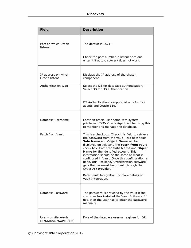
Discovery
© Copyright IBM Corporation 2017
Field Description
Port on which Oracle listens
The default is 1521.
Check the port number in listener.ora and enter it if auto-discovery does not work.
IP address on which
Oracle listens
Displays the IP address of the chosen
component.
Authentication type Select the DB for database authentication. Select OS for OS authentication.
OS Authentication is supported only for local agents and Oracle 11g.
Database Username
Enter an oracle user name with system privileges. IBM’s Oracle Agent will be using this
to monitor and manage the database.
Fetch from Vault This is a checkbox. Check this field to retrieve the password from the Vault. Two new fields Safe Name and Object Name will be
displayed on selecting the Fetch from vault check box. Enter the Safe Name and Object Name for the identified account. This information should be the same as what is configured in Vault. Once this configuration is done, IBM Resiliency Orchestration software
gets the password from Vault through the Cyber Ark provider.
Refer Vault Integration for more details on Vault Integration.
Database Password
The password is provided by the Vault if the
customer has installed the Vault Software. If not, then the user has to enter the password manually.
User's privilege/role (SYSDBA/SYSOPER/etc)
Role of the database username given for DR
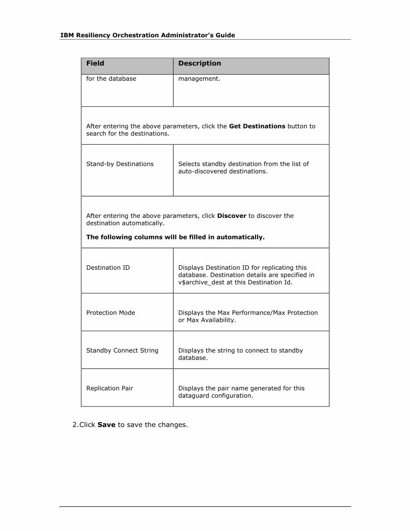
IBM Resiliency Orchestration Administrator’s Guide
Field Description
for the database management.
After entering the above parameters, click the Get Destinations button to search for the destinations.
Stand-by Destinations
Selects standby destination from the list of
auto-discovered destinations.
After entering the above parameters, click Discover to discover the destination automatically.
The following columns will be filled in automatically.
Destination ID
Displays Destination ID for replicating this database. Destination details are specified in
v$archive_dest at this Destination Id.
Protection Mode
Displays the Max Performance/Max Protection or Max Availability.
Standby Connect String
Displays the string to connect to standby database.
Replication Pair
Displays the pair name generated for this
dataguard configuration.
2. Click Save to save the changes.
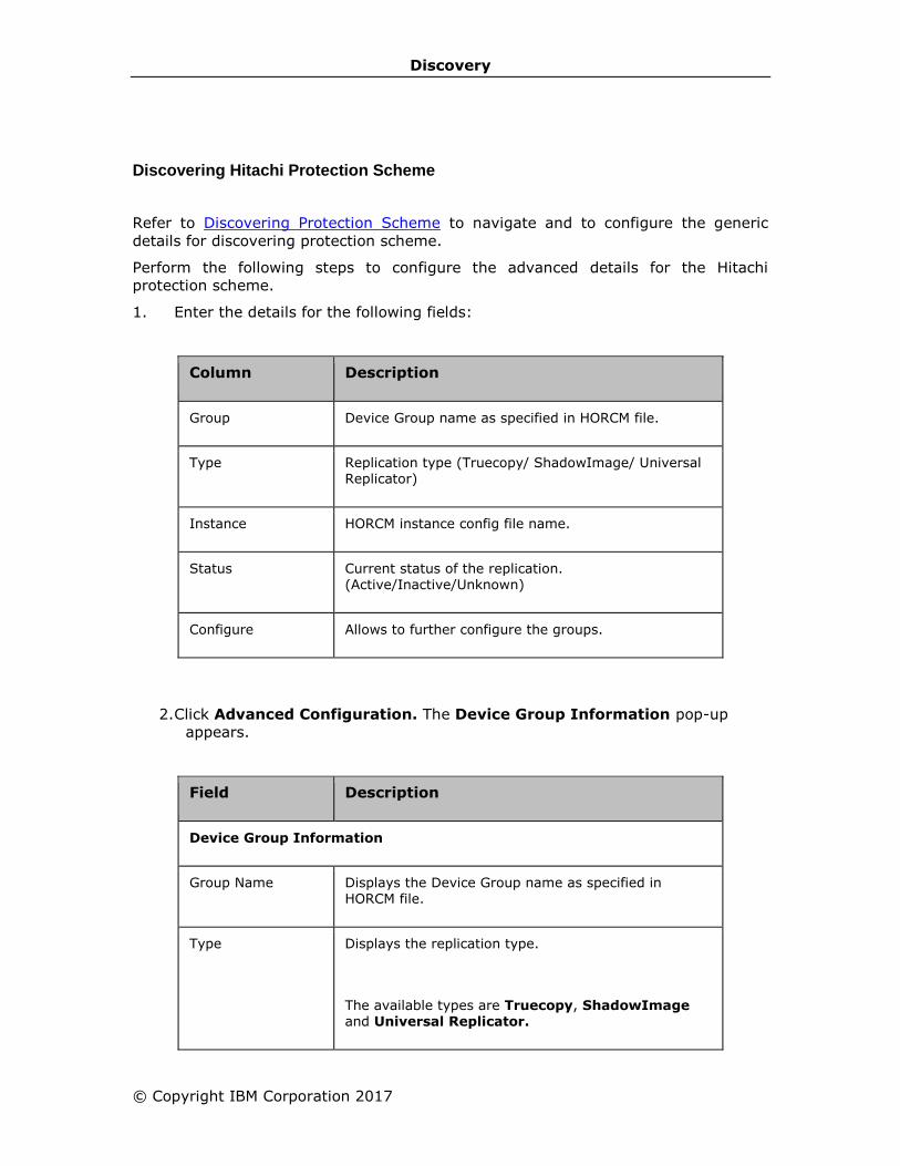
Discovery
© Copyright IBM Corporation 2017
Discovering Hitachi Protection Scheme
Refer to Discovering Protection Scheme to navigate and to configure the generic
details for discovering protection scheme.
Perform the following steps to configure the advanced details for the Hitachi
protection scheme.
1. Enter the details for the following fields:
Column Description
Group Device Group name as specified in HORCM file.
Type Replication type (Truecopy/ ShadowImage/ Universal Replicator)
Instance HORCM instance config file name.
Status Current status of the replication. (Active/Inactive/Unknown)
Configure Allows to further configure the groups.
2. Click Advanced Configuration. The Device Group Information pop-up
appears.
Field Description
Device Group Information
Group Name Displays the Device Group name as specified in HORCM file.
Type Displays the replication type.
The available types are Truecopy, ShadowImage and Universal Replicator.
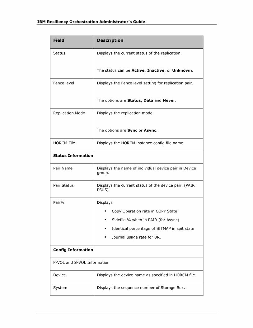
IBM Resiliency Orchestration Administrator’s Guide
Field Description
Status Displays the current status of the replication.
The status can be Active, Inactive, or Unknown.
Fence level Displays the Fence level setting for replication pair.
The options are Status, Data and Never.
Replication Mode Displays the replication mode.
The options are Sync or Async.
HORCM File Displays the HORCM instance config file name.
Status Information
Pair Name Displays the name of individual device pair in Device
group.
Pair Status Displays the current status of the device pair. (PAIR PSUS)
Pair% Displays
▪ Copy Operation rate in COPY State
▪ Sidefile % when in PAIR (for Async)
▪ Identical percentage of BITMAP in spit state
▪ Journal usage rate for UR.
Config Information
P-VOL and S-VOL Information
Device Displays the device name as specified in HORCM file.
System Displays the sequence number of Storage Box.

Discovery
© Copyright IBM Corporation 2017
Field Description
Port Displays the port number of the device.
Target Displays the target Id of the device.
LUN Displays the Logical Unit Number of the device.
Vol Size[MB] Enter the size of device.
This field is mandatory.
Enter Service Name Displays the protection scheme service name.
Enter Sidefile % Enter/Displays the maximum cache % available for use by Truecopy async sidefiles.
It displays the auto-discovered value. With certain older version of CCI software, it is not possible to auto-discover. In such cases, user needs to enter the value. For that please refer to Hitachi Truecopy
documentation to find out how to get this value.
3. Click Save in the Device Group Information page.
4. Click Finish.
Note:
Auto Discovery would return only those Device Group for which both the HORCM
instances are running. The Device Group for which no HORCM instance is running or
only one of the HORCM instance is running cannot be auto discovered.

IBM Resiliency Orchestration Administrator’s Guide
Discovering Custom Replicator Protection Scheme
Custom Replicator in IBM Resiliency Orchestration is introduced to provide:
▪ Ability for doing health monitoring of Replication in terms of object status
changes and group status changes for unsupported replication by addition of
scripts on field.
▪ Start and Stop of replication from manage replication page by addition of
script on field.
▪ Raise group event and agent event for replication UP and DOWN. User need
not write raise event scripts for it.
Refer to Discovering Protection Scheme to navigate and to configure the generic
details for discovering Custom replicator.
The advanced configuration details varies for different custom replicators. You have
to enter appropriate information in the fields which are displayed based on the
selected replicator. Click Save to save changes.
Discovering EMC SRDF Protection Scheme
Refer to Discovering Protection Scheme to navigate and to configure the generic
details for discovering protection scheme.
Perform the following steps to configure the advanced details for the EMC SRDF
protection scheme.
1. To discover the new agent, register and configure the agent and then click
Discover Now button.
or
Select the Management Host to discover already registered and configured
agents.
Under Select SRDF Subsystem section, all the devices, groups and its RDFs &
BCVs will be listed.
2. Click Advanced Configuration. The SRDF Details pop-up appears.
The following details are shown for RDF devices:
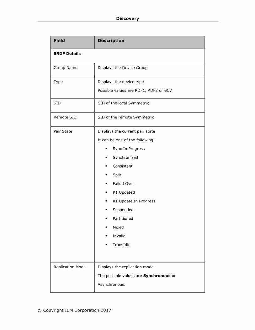
Discovery
© Copyright IBM Corporation 2017
Field Description
SRDF Details
Group Name Displays the Device Group
Type Displays the device type
Possible values are RDF1, RDF2 or BCV
SID SID of the local Symmetrix
Remote SID SID of the remote Symmetrix
Pair State Displays the current pair state
It can be one of the following:
▪ Sync In Progress
▪ Synchronized
▪ Consistent
▪ Split
▪ Failed Over
▪ R1 Updated
▪ R1 Update In Progress
▪ Suspended
▪ Partitioned
▪ Mixed
▪ Invalid
▪ TransIdle
Replication Mode Displays the replication mode.
The possible values are Synchronous or
Asynchronous.
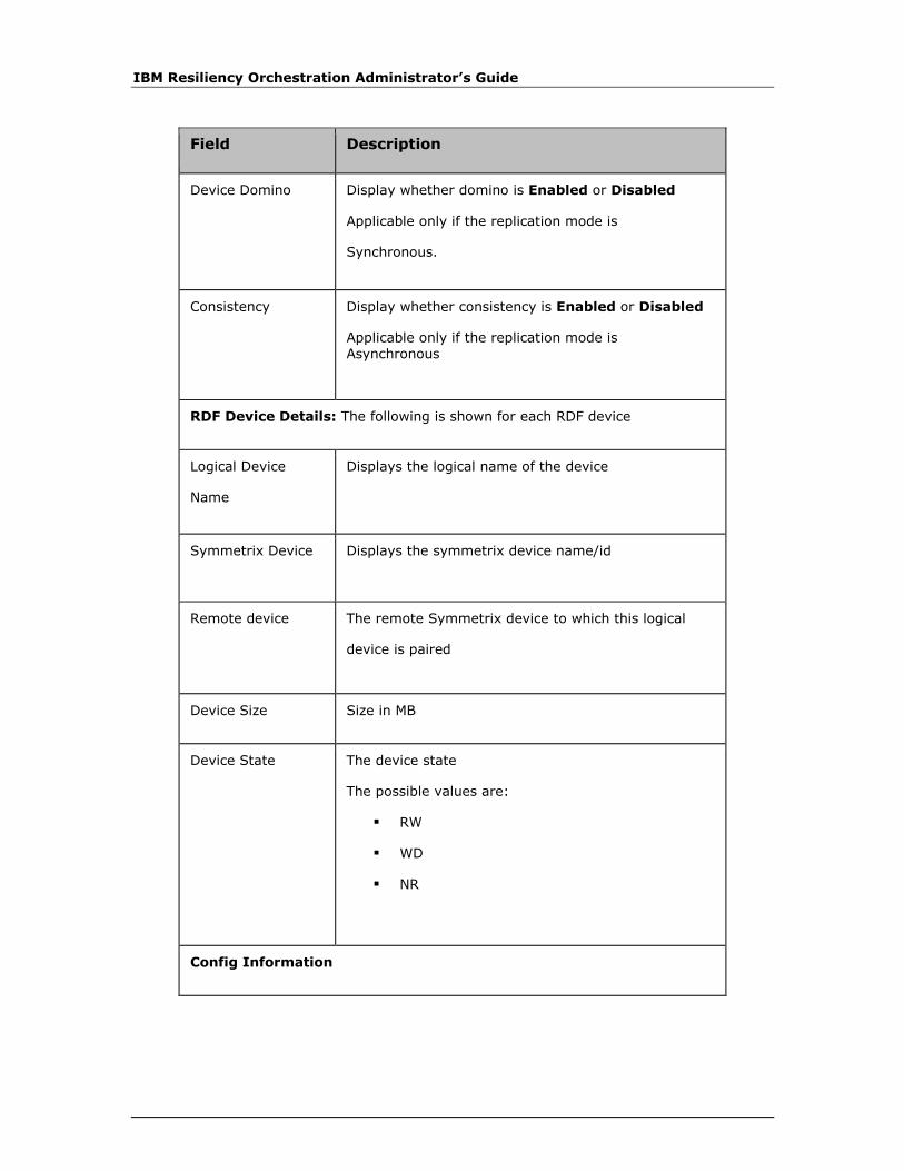
IBM Resiliency Orchestration Administrator’s Guide
Field Description
Device Domino Display whether domino is Enabled or Disabled
Applicable only if the replication mode is
Synchronous.
Consistency Display whether consistency is Enabled or Disabled
Applicable only if the replication mode is Asynchronous
RDF Device Details: The following is shown for each RDF device
Logical Device
Name
Displays the logical name of the device
Symmetrix Device Displays the symmetrix device name/id
Remote device The remote Symmetrix device to which this logical
device is paired
Device Size Size in MB
Device State The device state
The possible values are:
▪ RW
▪ WD
▪ NR
Config Information
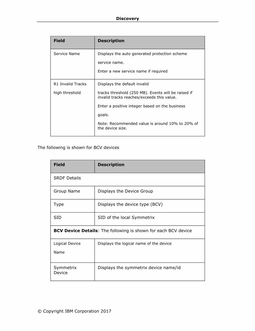
Discovery
© Copyright IBM Corporation 2017
Field Description
Service Name Displays the auto generated protection scheme
service name.
Enter a new service name if required
R1 Invalid Tracks
high threshold
Displays the default invalid
tracks threshold (250 MB). Events will be raised if invalid tracks reaches/exceeds this value.
Enter a positive integer based on the business
goals.
Note: Recommended value is around 10% to 20% of the device size.
The following is shown for BCV devices
Field Description
SRDF Details
Group Name Displays the Device Group
Type Displays the device type (BCV)
SID SID of the local Symmetrix
BCV Device Details: The following is shown for each BCV device
Logical Device
Name
Displays the logical name of the device
Symmetrix
Device
Displays the symmetrix device name/id
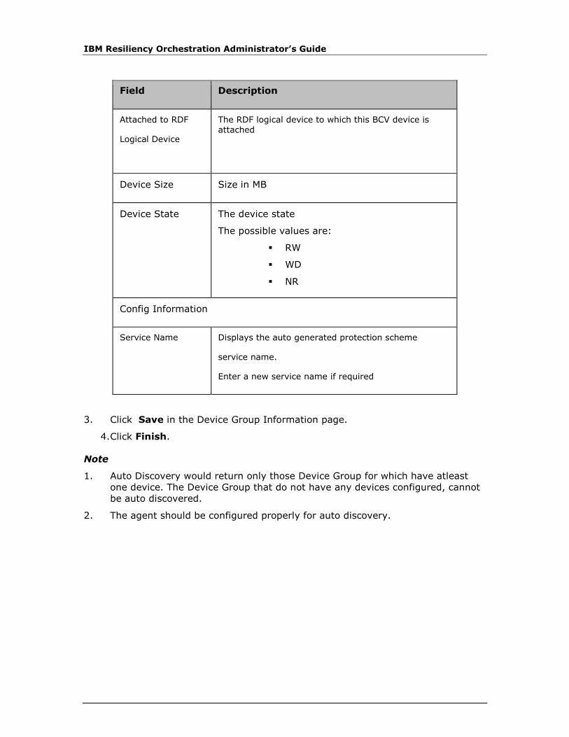
IBM Resiliency Orchestration Administrator’s Guide
Field Description
Attached to RDF
Logical Device
The RDF logical device to which this BCV device is attached
Device Size Size in MB
Device State The device state
The possible values are:
▪ RW
▪ WD
▪ NR
Config Information
Service Name Displays the auto generated protection scheme
service name.
Enter a new service name if required
3. Click Save in the Device Group Information page.
4. Click Finish.
Note
1. Auto Discovery would return only those Device Group for which have atleast
one device. The Device Group that do not have any devices configured, cannot
be auto discovered.
2. The agent should be configured properly for auto discovery.

Discovery
© Copyright IBM Corporation 2017
Discovering PostgreSQL SR Protection Scheme
Refer to Discovering Protection Scheme to navigate and to configure the generic
details for discovering protection scheme.
A Protection Scheme is any protection mechanism that protects data. You should
discover the component and dataset before proceeding with the protection scheme
discovery.
Note
There is no specific agent for PostgreSQL SR Protection Scheme. Its status depends
upon replication status.
To discover a new Protection Scheme, perform following steps:
1. Click DISCOVER > Subsystems on the navigation bar. The Subsystems
page appears.
2. Select PostgreSQL SR from the Create New drop-down list at the top right
corner of the Subsystems page. The drop-down list displays all the Protection
Schemes that can be created.
3. Click Go. The Protection Scheme Discovery page appears and the
Subsystems side bar page displays list of all the Protection Schemes
discovered.
Provide necessary information on the following fields to configure Protection
Scheme:
Field Description
Type Displays the type of protection scheme.
The protection scheme is displayed only if its agent is connected to the IBM Resiliency Orchestration server. This is applicable for all protection schemes
except for the one that requires manual discovery.
Name
By-default, the protection schema is auto populated which is a combination of protection type and
component name.
OR
Provide a unique name for protection scheme.

IBM Resiliency Orchestration Administrator’s Guide
Field Description
This field accepts alphanumeric characters, and underscores and the name must start with an alphabet. It should not have a space.
This field is mandatory.
Management Host Select DR Solution specific Component from the
drop-down list to be associated to the
protection scheme.
If no components are present, abort Protection Scheme discovery and initiate Component discovery.
PostgreSQL Home The directory where PostgreSQL is installed
This field is mandatory
PostgreSQL Data The cluster data directory
This field is mandatory
4. Click Save to save the entered details to complete protection scheme setup.
Discovering IBM Global Mirror Protection Scheme
Refer to Discovering Protection Scheme to navigate and to configure the generic
details for discovering protection scheme.
It is useful for the solution and for the IBM administrator if the two sets of
parameters are identical to the extent possible. For example, Primary and DR should
have the same LUN ids. The protection scheme discovery parameters are listed in
the table below.
Perform the following steps to configure the advanced details for the IBM Global
Mirror protection scheme.
1. Enter the details for the following fields:

Discovery
© Copyright IBM Corporation 2017
Discovery
Parameters
Description
HMC Hardware Management Console IP Address.
DeviceID Identifies Production Storage Unit, e.g. IBM 1750-6830402.
RemoteDeviceID Identifies DR Storage Unit
HMC_User HMC User Name
HMC Password File
Password file with full path, e.g. /opt/<password file name>
DSCLI Command Path
DSCLI binary with full path, e.g. /opt/dscli/dscli
Global Mirror Session
Global Mirror Session Id
Local LUN List Global Copy LUN list, e.g. 0.02, 0203, 0204 [A- LUN list].
Remote LUN List Remote Global Copy LUN list [B- LUN list].
Local Flash Copy LUN List 1
Local Flash Copy LUN list [C- LUN list].
Local Flash Copy LUN List 2
Local Flash Copy LUN list [D- LUN list].
2. Click Save.
Note:
If the protection object to be discovered is of primary, then A, C and D LUN
information should be of primary and B should be of DR.
If the protection object to be discovered is of DR, then A, C and D LUN information
should be of the DR and B should be of primary.
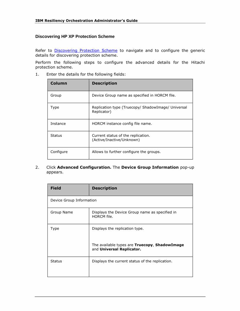
IBM Resiliency Orchestration Administrator’s Guide
Discovering HP XP Protection Scheme
Refer to Discovering Protection Scheme to navigate and to configure the generic
details for discovering protection scheme.
Perform the following steps to configure the advanced details for the Hitachi
protection scheme.
1. Enter the details for the following fields:
Column Description
Group Device Group name as specified in HORCM file.
Type Replication type (Truecopy/ ShadowImage/ Universal Replicator)
Instance HORCM instance config file name.
Status Current status of the replication. (Active/Inactive/Unknown)
Configure Allows to further configure the groups.
2. Click Advanced Configuration. The Device Group Information pop-up
appears.
Field Description
Device Group Information
Group Name Displays the Device Group name as specified in HORCM file.
Type Displays the replication type.
The available types are Truecopy, ShadowImage and Universal Replicator.
Status Displays the current status of the replication.
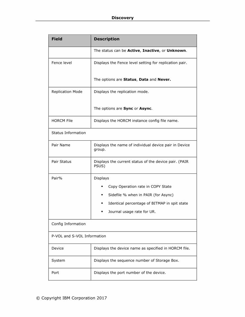
Discovery
© Copyright IBM Corporation 2017
Field Description
The status can be Active, Inactive, or Unknown.
Fence level Displays the Fence level setting for replication pair.
The options are Status, Data and Never.
Replication Mode Displays the replication mode.
The options are Sync or Async.
HORCM File Displays the HORCM instance config file name.
Status Information
Pair Name Displays the name of individual device pair in Device group.
Pair Status Displays the current status of the device pair. (PAIR PSUS)
Pair% Displays
▪ Copy Operation rate in COPY State
▪ Sidefile % when in PAIR (for Async)
▪ Identical percentage of BITMAP in spit state
▪ Journal usage rate for UR.
Config Information
P-VOL and S-VOL Information
Device Displays the device name as specified in HORCM file.
System Displays the sequence number of Storage Box.
Port Displays the port number of the device.

IBM Resiliency Orchestration Administrator’s Guide
Field Description
Target Displays the target Id of the device.
LUN Displays the Logical Unit Number of the device.
Vol Size[MB] Enter the size of device.
This field is mandatory.
Enter Service Name Displays the protection scheme service name.
Enter Sidefile % Enter/Displays the maximum cache % available for use by Truecopy async sidefiles.
It displays the auto-discovered value. With certain older version of CCI software, it is not possible to auto-discover. In such cases, user needs to enter the value. For that please refer to Hitachi Truecopy
documentation to find out how to get this value.
3. Click Save in the Device Group Information page.
4. Click Finish.
Note:
Auto Discovery would return only those Device Group for which both the HORCM
instances are running. The Device Group for which no HORCM instance is running or
only one of the HORCM instance is running cannot be auto discovered.

Discovery
© Copyright IBM Corporation 2017
Discovering HADR Protection Scheme
Refer to Discovering Protection Scheme to navigate and to configure the generic
details for discovering protection scheme.
A Protection Scheme is any protection mechanism that protects data. You should
discover the component and dataset before proceeding with the protection scheme
discovery.
Note:
There is no specific agent for HADR Protection Scheme. Its status depends upon
replication status.
To discover a new Protection Scheme, perform following steps:
1. Click DISCOVER > Subsystems on the navigation bar. The Subsystems
page appears.
2. Select HADR from the Create New drop-down list at the top right corner of
the Subsystems page. The drop-down list displays all the Protection Schemes
that can be created.
3. Click Go. The Protection Scheme Discovery page appears and the
Subsystems side bar page displays list of all the Protection Schemes
discovered.
Provide necessary information on the following fields to configure Protection Scheme.
Field Description
Type Displays the type of protection scheme.
The protection scheme is displayed only if its agent
is connected to the IBM Resiliency Orchestration ™ server. This is applicable for all protection schemes except for the one that requires manual discovery.
Name
Enter a unique name for protection scheme.
This field accepts alphanumeric characters, spaces
and underscores and the name must start with an alphabet.
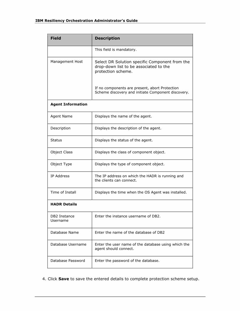
IBM Resiliency Orchestration Administrator’s Guide
Field Description
This field is mandatory.
Management Host Select DR Solution specific Component from the
drop-down list to be associated to the
protection scheme.
If no components are present, abort Protection Scheme discovery and initiate Component discovery.
Agent Information
Agent Name Displays the name of the agent.
Description Displays the description of the agent.
Status Displays the status of the agent.
Object Class Displays the class of component object.
Object Type Displays the type of component object.
IP Address The IP address on which the HADR is running and the clients can connect.
Time of Install Displays the time when the OS Agent was installed.
HADR Details
DB2 Instance Username
Enter the instance username of DB2.
Database Name Enter the name of the database of DB2
Database Username Enter the user name of the database using which the agent should connect.
Database Password Enter the password of the database.
4. Click Save to save the entered details to complete protection scheme setup.
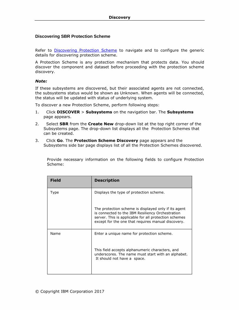
Discovery
© Copyright IBM Corporation 2017
Discovering SBR Protection Scheme
Refer to Discovering Protection Scheme to navigate and to configure the generic
details for discovering protection scheme.
A Protection Scheme is any protection mechanism that protects data. You should
discover the component and dataset before proceeding with the protection scheme
discovery.
Note:
If these subsystems are discovered, but their associated agents are not connected,
the subsystems status would be shown as Unknown. When agents will be connected,
the status will be updated with status of underlying system.
To discover a new Protection Scheme, perform following steps:
1. Click DISCOVER > Subsystems on the navigation bar. The Subsystems
page appears.
2. Select SBR from the Create New drop-down list at the top right corner of the
Subsystems page. The drop-down list displays all the Protection Schemes that
can be created.
3. Click Go. The Protection Scheme Discovery page appears and the
Subsystems side bar page displays list of all the Protection Schemes discovered.
Provide necessary information on the following fields to configure Protection
Scheme:
Field Description
Type Displays the type of protection scheme.
The protection scheme is displayed only if its agent
is connected to the IBM Resiliency Orchestration server. This is applicable for all protection schemes except for the one that requires manual discovery.
Name
Enter a unique name for protection scheme.
This field accepts alphanumeric characters, and
underscores. The name must start with an alphabet. It should not have a space.
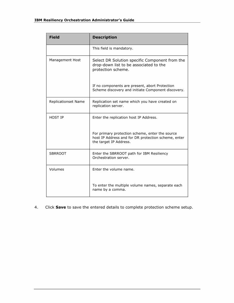
IBM Resiliency Orchestration Administrator’s Guide
Field Description
This field is mandatory.
Management Host Select DR Solution specific Component from the
drop-down list to be associated to the
protection scheme.
If no components are present, abort Protection Scheme discovery and initiate Component discovery.
Replicationset Name Replication set name which you have created on replication server.
HOST IP Enter the replication host IP Address.
For primary protection scheme, enter the source
host IP Address and for DR protection scheme, enter the target IP Address.
SBRROOT Enter the SBRROOT path for IBM Resiliency Orchestration server.
Volumes Enter the volume name.
To enter the multiple volume names, separate each name by a comma.
4. Click Save to save the entered details to complete protection scheme setup.

Discovery
© Copyright IBM Corporation 2017
Discovering MySQL SR Protection Scheme
Refer to Discovering Protection Scheme to navigate and to configure the generic
details for discovering protection scheme.
A Protection Scheme is any protection mechanism that protects data. You should
discover the component and dataset before proceeding with the protection scheme
discovery.
Note:
There is no specific agent for MySQL SR Protection Scheme. Its status depends upon
replication status.
To discover a new Protection Scheme, perform following steps:
1. Click DISCOVER > Subsystems on the navigation bar. The Subsystems
page appears.
2. Select MySQL SR from the Create New drop-down list at the top right corner
of the Subsystems page. The drop-down list displays all the Protection
Schemes that can be created.
3. Click Go. The Protection Scheme Discovery page appears and the
Subsystems side bar page displays list of all the Protection Schemes
discovered.
Provide necessary information on the following fields to configure Protection Scheme:
Field Description
Type Displays the type of protection scheme.
The protection scheme is displayed only if its agent
is connected to the IBM Resiliency Orchestration ™ server. This is applicable for all protection schemes except for the one that requires manual discovery.
Name
Enter a unique name for protection scheme.
This field accepts alphanumeric characters, and
underscores and the name must start with an alphabet. It should not have a space.

IBM Resiliency Orchestration Administrator’s Guide
Field Description
This field is mandatory.
Management Host Select DR Solution specific Component from the
drop-down list to be associated to the
protection scheme.
If no components are present, abort Protection Scheme discovery and initiate Component discovery.
IP Address The IP address on which the MySQL is running and the clients can connect
User Name The user name using which the agent should connect
Password The password for the user
Port number The port number on which the MySQL is listening and the clients can connect
4. Click Save to save the entered details to complete protection scheme setup.
Discovering MS Exchange Protection Scheme
Refer to Discovering Protection Scheme to navigate and to configure the generic
details for discovering protection scheme.
A Protection Scheme is any protection mechanism that protects data. You should
discover the component and dataset before proceeding with the protection scheme
discovery.
Note:
The MS-Exchange Replication Agent will run under the component privileges.
To discover a new Protection Scheme, perform following steps:
1. Click DISCOVER > Subsystems on the navigation bar. The Subsystems
page appears.
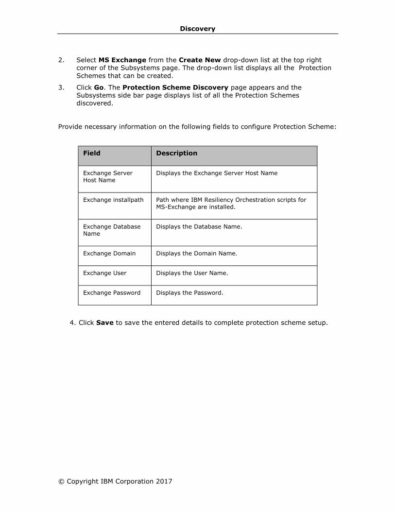
Discovery
© Copyright IBM Corporation 2017
2. Select MS Exchange from the Create New drop-down list at the top right
corner of the Subsystems page. The drop-down list displays all the Protection
Schemes that can be created.
3. Click Go. The Protection Scheme Discovery page appears and the
Subsystems side bar page displays list of all the Protection Schemes
discovered.
Provide necessary information on the following fields to configure Protection Scheme:
Field Description
Exchange Server Host Name
Displays the Exchange Server Host Name
Exchange installpath Path where IBM Resiliency Orchestration scripts for MS-Exchange are installed.
Exchange Database Name
Displays the Database Name.
Exchange Domain Displays the Domain Name.
Exchange User Displays the User Name.
Exchange Password Displays the Password.
4. Click Save to save the entered details to complete protection scheme setup.
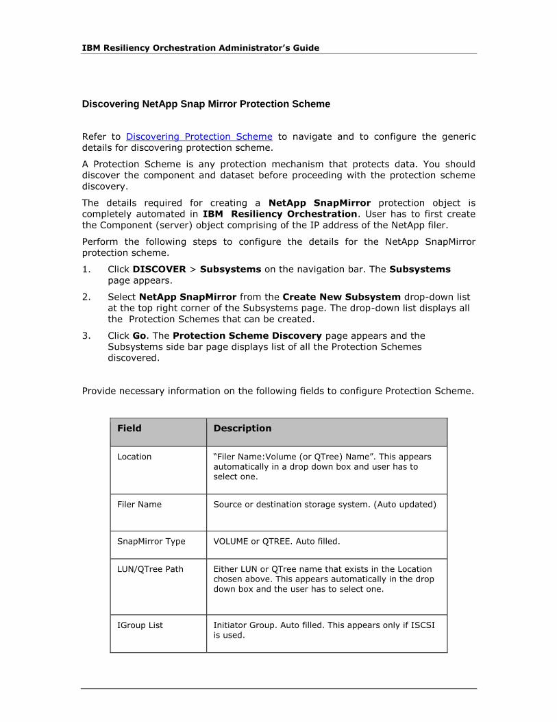
IBM Resiliency Orchestration Administrator’s Guide
Discovering NetApp Snap Mirror Protection Scheme
Refer to Discovering Protection Scheme to navigate and to configure the generic
details for discovering protection scheme.
A Protection Scheme is any protection mechanism that protects data. You should
discover the component and dataset before proceeding with the protection scheme
discovery.
The details required for creating a NetApp SnapMirror protection object is
completely automated in IBM Resiliency Orchestration. User has to first create
the Component (server) object comprising of the IP address of the NetApp filer.
Perform the following steps to configure the details for the NetApp SnapMirror
protection scheme.
1. Click DISCOVER > Subsystems on the navigation bar. The Subsystems
page appears.
2. Select NetApp SnapMirror from the Create New Subsystem drop-down list
at the top right corner of the Subsystems page. The drop-down list displays all
the Protection Schemes that can be created.
3. Click Go. The Protection Scheme Discovery page appears and the
Subsystems side bar page displays list of all the Protection Schemes
discovered.
Provide necessary information on the following fields to configure Protection Scheme.
Field Description
Location “Filer Name:Volume (or QTree) Name”. This appears automatically in a drop down box and user has to select one.
Filer Name Source or destination storage system. (Auto updated)
SnapMirror Type VOLUME or QTREE. Auto filled.
LUN/QTree Path Either LUN or QTree name that exists in the Location chosen above. This appears automatically in the drop down box and the user has to select one.
IGroup List Initiator Group. Auto filled. This appears only if ISCSI is used.
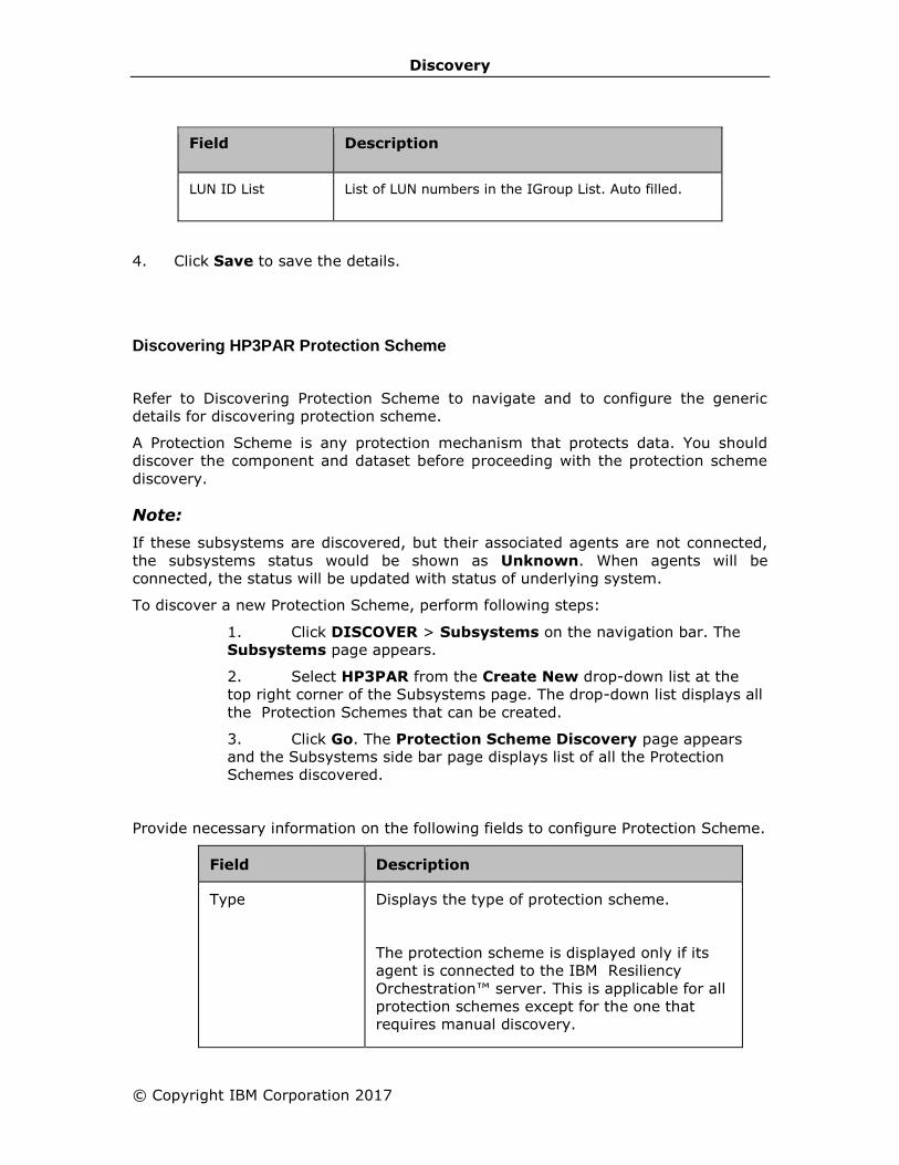
Discovery
© Copyright IBM Corporation 2017
Field Description
LUN ID List List of LUN numbers in the IGroup List. Auto filled.
4. Click Save to save the details.
Discovering HP3PAR Protection Scheme
Refer to Discovering Protection Scheme to navigate and to configure the generic
details for discovering protection scheme.
A Protection Scheme is any protection mechanism that protects data. You should
discover the component and dataset before proceeding with the protection scheme
discovery.
Note:
If these subsystems are discovered, but their associated agents are not connected,
the subsystems status would be shown as Unknown. When agents will be
connected, the status will be updated with status of underlying system.
To discover a new Protection Scheme, perform following steps:
1. Click DISCOVER > Subsystems on the navigation bar. The
Subsystems page appears.
2. Select HP3PAR from the Create New drop-down list at the
top right corner of the Subsystems page. The drop-down list displays all
the Protection Schemes that can be created.
3. Click Go. The Protection Scheme Discovery page appears
and the Subsystems side bar page displays list of all the Protection
Schemes discovered.
Provide necessary information on the following fields to configure Protection Scheme.
Field Description
Type Displays the type of protection scheme.
The protection scheme is displayed only if its
agent is connected to the IBM Resiliency
Orchestration™ server. This is applicable for all
protection schemes except for the one that
requires manual discovery.

IBM Resiliency Orchestration Administrator’s Guide
Name
Enter a unique name for protection scheme.
This field accepts alphanumeric characters, and
underscores and the name must start with an
alphabet. It should not have a space.
This field is mandatory.
Management Host Select DR Solution specific Component from the
drop-down list to be associated to the
protection scheme.
If no components are present, abort Protection
Scheme discovery and initiate Component
discovery.
Remote Copy
Volume Group
Enter the Remote Copy Volume group for the
management host that ensures write order
consistency.
Virtual Volume List Enter the Virtual Volume List that is supported
by the Remote Copy Volume Group.
Lun List Enter the Logical unit number list for the
management host.
Host List List of host machines for the management host.
4. Click Save to save the entered details to complete protection scheme
setup.
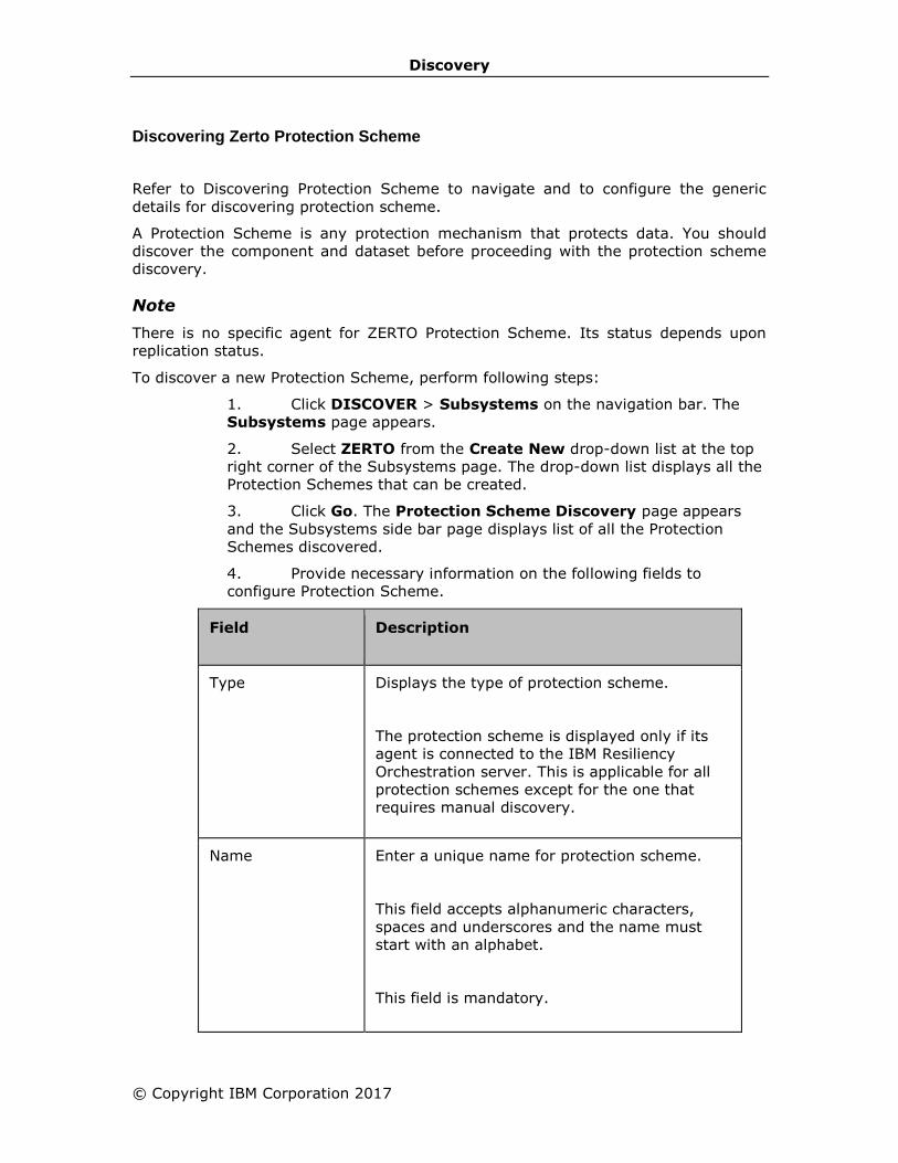
Discovery
© Copyright IBM Corporation 2017
Discovering Zerto Protection Scheme
Refer to Discovering Protection Scheme to navigate and to configure the generic
details for discovering protection scheme.
A Protection Scheme is any protection mechanism that protects data. You should
discover the component and dataset before proceeding with the protection scheme
discovery.
Note
There is no specific agent for ZERTO Protection Scheme. Its status depends upon
replication status.
To discover a new Protection Scheme, perform following steps:
1. Click DISCOVER > Subsystems on the navigation bar. The
Subsystems page appears.
2. Select ZERTO from the Create New drop-down list at the top
right corner of the Subsystems page. The drop-down list displays all the
Protection Schemes that can be created.
3. Click Go. The Protection Scheme Discovery page appears
and the Subsystems side bar page displays list of all the Protection
Schemes discovered.
4. Provide necessary information on the following fields to
configure Protection Scheme.
Field Description
Type Displays the type of protection scheme.
The protection scheme is displayed only if its
agent is connected to the IBM Resiliency
Orchestration server. This is applicable for all
protection schemes except for the one that
requires manual discovery.
Name
Enter a unique name for protection scheme.
This field accepts alphanumeric characters,
spaces and underscores and the name must
start with an alphabet.
This field is mandatory.

IBM Resiliency Orchestration Administrator’s Guide
Management Host Select DR Solution specific Component from the
drop-down list to be associated to the
protection scheme.
If no components are present, abort Protection
Scheme discovery and initiate Component
discovery.
Agent Information
Agent Name Displays the name of the agent.
Description Displays the description of the agent.
Status Displays the status of the agent.
Object Class Displays the class of component object.
Object Type Displays the type of component object.
IP Address The IP address on which the ZERTO is running
and the clients can connect.
Time of Install Displays the time when the OS Agent was
installed.
ZERTO Details
ZVM IP Zerto Virtual Manager IP address.
ZVM API Port Zerto Virtual Manager API Port.
ZVM CLI Port Zerto Virtual Manager CLI Port.
*ZVM Username Zerto Virtual Manager user name.
*ZVM Password Enter the password of the database.
VPG Name Enter the name of the Virtual Private Group.

Discovery
© Copyright IBM Corporation 2017
4. Click Save to save the entered details to complete protection scheme
setup.
*Indicates ZVM login Credentials should be vCenter Credentials for which the ZVM is
configured.

IBM Resiliency Orchestration Administrator’s Guide
Modifying Protection Schemes
Click IBM Resiliency Orchestration Server User Role Management to see the
privileges.
To modify Protection Schemes, perform following steps:
1. Click DISCOVER > Subsystems on the navigation bar. The
Subsystems page appears.
2.
3. Click Protection Schemes tab. The discovered Protection
Schemes are displayed.
4. Click corresponding to the Protection Scheme to be
modified. The Protection Scheme Discovery page appears.
5. Modify the required fields. For more information, refer to
Discovering Protection Scheme.
6. Click Save to save the changes.
OR
Click Go Back to quit current operation.
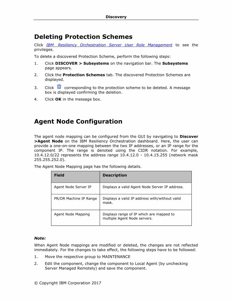
Discovery
© Copyright IBM Corporation 2017
Deleting Protection Schemes
Click IBM Resiliency Orchestration Server User Role Management to see the
privileges.
To delete a discovered Protection Scheme, perform the following steps:
1. Click DISCOVER > Subsystems on the navigation bar. The Subsystems
page appears.
2. Click the Protection Schemes tab. The discovered Protection Schemes are
displayed.
3. Click corresponding to the protection scheme to be deleted. A message
box is displayed confirming the deletion.
4. Click OK in the message box.
Agent Node Configuration
The agent node mapping can be configured from the GUI by navigating to Discover
>Agent Node on the IBM Resiliency Orchestration dashboard. Here, the user can
provide a one-on-one mapping between the two IP addresses, or an IP range for the
component IP. The range is denoted using the CIDR notation. For example,
10.4.12.0/22 represents the address range 10.4.12.0 - 10.4.15.255 (network mask
255.255.252.0).
The Agent Node Mapping page has the following details.
Field Description
Agent Node Server IP Displays a valid Agent Node Server IP address.
PR/DR Machine IP Range Displays a valid IP address with/without valid mask.
Agent Node Mapping Displays range of IP which are mapped to multiple Agent Node servers.
Note:
When Agent Node mappings are modified or deleted, the changes are not reflected
immediately. For the changes to take effect, the following steps have to be followed:
1. Move the respective group to MAINTENANCE
2. Edit the component, change the component to Local Agent (by unchecking
Server Managed Remotely) and save the component.
IBM Resiliency Orchestration Administrator’s Guide
3. Again Edit the component, change the component to Remote Agent (by
checking Server Managed Remotely and providing credentials) and save the
component. This will take the latest Agent Node mapping configured.
Converged
Converged infrastructure packages multiple information technology (IT) components
into a single, optimized computing solution. Components of a converged
infrastructure solution include servers, data storage devices, networking equipment
and software for IT infrastructure management, automation and orchestration.
This chapter describes how to work with UCS Directors and UCS Director DR Map for
DR.
UCS Directors
Cisco UCS Director unifies and automates end-to-end IT converged infrastructure
management processes by abstracting the complexity of individual devices,
hypervisors, and virtual machine.
UCS Directors section explains the following:
Adding UCS Directors
Modifying UCS Directors
Deleting UCS Directors
Listing UCS Directors
UCS Director DR Map for DR
Virtual Data Centre (vDC) Map for DR is used to configure IBM Resiliency
Orchestration on which vDC on the DR site should the resources be allocated for DR
for a given VM on the primary. This map needs to be created for each vDC on the
primary for which DR might be needed.
UCS Director DR Map for DR section explains the following:
Adding UCS Director vCD Map for DR
Deleting UCS Director vCD Map for DR
Listing UCS Director vCD Map for DR

Discovery
© Copyright IBM Corporation 2017
UCS Directors
Adding UCS Directors
Click IBM Resiliency Orchestration Server User Role Management to see the
privileges.
To add a new UCS director in the existing DR environment, perform the following
steps:
1. Click DISCOVER > Converged tab on the navigation bar. The Converged
page appears with the following configured values.
▪ NAME
▪ SITE
▪ CREDENTIAL STATUS
Click Add UCS Director link at the top right corner of the Converged page
should navigate to 'Add UCS Director' page.
Configure the following field elements.
Field Description
Name Provide a unique name to the UCS Director being
created.
This field is mandatory.
Note:
This field accepts up to 32 alphanumeric characters, spaces and underscores. The UCS Director name can start with an alphabet.
SITE Select the Site from the drop-down list.
Access Key To obtain the Access key:
▪ Login to CISCO UCS Director
▪ click on Admin link,select the User information window.
▪ Click on the Copy key button from the Advanced tab, to copy the access key.
▪ Paste the Access key in IBM Resiliency Orchestration server's Add UCS director page.
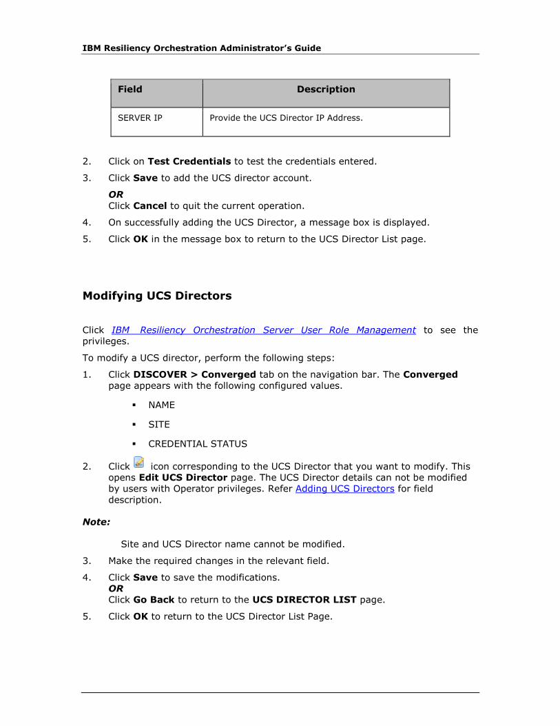
IBM Resiliency Orchestration Administrator’s Guide
Field Description
SERVER IP Provide the UCS Director IP Address.
2. Click on Test Credentials to test the credentials entered.
3. Click Save to add the UCS director account.
OR
Click Cancel to quit the current operation.
4. On successfully adding the UCS Director, a message box is displayed.
5. Click OK in the message box to return to the UCS Director List page.
Modifying UCS Directors
Click IBM Resiliency Orchestration Server User Role Management to see the
privileges.
To modify a UCS director, perform the following steps:
1. Click DISCOVER > Converged tab on the navigation bar. The Converged
page appears with the following configured values.
▪ NAME
▪ SITE
▪ CREDENTIAL STATUS
2. Click icon corresponding to the UCS Director that you want to modify. This
opens Edit UCS Director page. The UCS Director details can not be modified
by users with Operator privileges. Refer Adding UCS Directors for field
description.
Note:
Site and UCS Director name cannot be modified.
3. Make the required changes in the relevant field.
4. Click Save to save the modifications.
OR
Click Go Back to return to the UCS DIRECTOR LIST page.
5. Click OK to return to the UCS Director List Page.

Discovery
© Copyright IBM Corporation 2017
Delete UCS directors
Click IBM Resiliency Orchestration Server User Role Management to see the
privileges.
To delete a UCS Director, perform the following steps:
1. Click DISCOVER > Converged tab on the navigation bar. The Converged
page appears with the following configured values.
• Name
• Site
• Status
2. Click the icon corresponding to the UCS Director that you want to delete. A
message box is displayed confirming the deletion.
3. Click OK in the message box. The UCS director account should be deleted.
Listing UCS Directors
To view the UCS Directors created or available in a Resiliency Orchestration
environment, click DISCOVER > Converged on the navigation bar.
Click IBM Resiliency Orchestration Server User Role Management to see the
privileges.
The Converged page displays following details in a tabular form:
Field Description
Name Displays the name.
Site Displays the site.
Credential Status Displays the status of the site.
Status can be Unknown/Active/Inactive.
UCS Director vDC Map for DR
Adding UCS Director vDC Map for DR

IBM Resiliency Orchestration Administrator’s Guide
Click IBM Resiliency Orchestration Server User Role Management to see the
privileges.
To create a new location in the existing DR environment, perform the following
steps:
1. Click DISCOVER > Converged on the navigation bar. The UCS Director vDC
Map for DR List appears with the following configured values.
• Name
• Primary UCS Director
• PRIMARY Group
• PRIMARY vDC
• DR UCS Director
• DR Group
• DR VDC
2. Click the Define vDC Map link at the bottom right corner of the Converged
page. The Define vDC Map for DR page is displayed.
Configure the following field elements.
Note:
▪ To create a UCD Director vDC Map, PR And DR UCSD accounts should be
created and its agents should be active and listed in Admin > Agents page.
Field Description
Name Displays the name of the UCS Director.
Primary UCS Director
Select the account from the drop down list.
This field is mandatory.
PRIMARY Group Select the group name from the drop down list.
This field is mandatory.
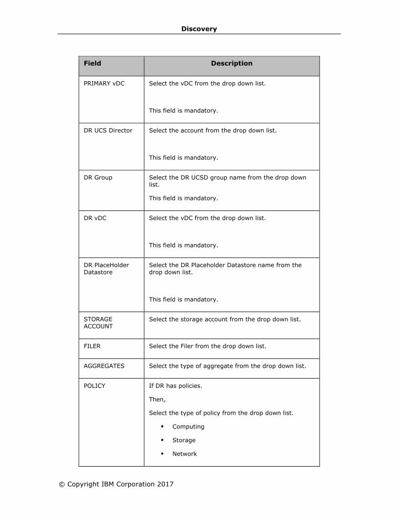
Discovery
© Copyright IBM Corporation 2017
Field Description
PRIMARY vDC Select the vDC from the drop down list.
This field is mandatory.
DR UCS Director Select the account from the drop down list.
This field is mandatory.
DR Group Select the DR UCSD group name from the drop down list.
This field is mandatory.
DR vDC Select the vDC from the drop down list.
This field is mandatory.
DR PlaceHolder
Datastore
Select the DR Placeholder Datastore name from the
drop down list.
This field is mandatory.
STORAGE ACCOUNT
Select the storage account from the drop down list.
FILER Select the Filer from the drop down list.
AGGREGATES Select the type of aggregate from the drop down list.
POLICY If DR has policies.
Then,
Select the type of policy from the drop down list.
▪ Computing
▪ Storage
▪ Network

IBM Resiliency Orchestration Administrator’s Guide
3. Click Save to add the UCS Director vDC Map for DR.
OR
Click Cancel to quit the current operation.
4. On successfully adding the UCS Director vDC Map for DR, a message box is
displayed.
5. Click OK in the message box to return to the Converged page.
Deleting UCS Director vDC Map for DR
Click IBM Resiliency Orchestration Server User Role Management to see the
privileges.
A UCS Director DR Map cannot be deleted, if there are components associated with
it.
To delete a UCS Director vDC Map, perform the following steps:
1. Click DISCOVER > Converged on the navigation bar. The UCS Director vDC
Map List page appears with the following configured values.
▪ Name
▪ Primary UCS Director
▪ Primary Group
▪ Primary vDC
▪ DR UCS Director
▪ DR Group
▪ DR vDC
2. Click the icon corresponding to the UCS Director vDC Map that you want to
delete. A message box is displayed confirming the deletion.
3. Click OK in the message box.
Listing UCS Director vDC Map for DR
To view the UCS Director DR Map created in a DR environment, click DISCOVER >
Converged on the navigation bar.
Click IBM Resiliency Orchestration Server User Role Management to see the
privileges.
The UCS DIRECTOR vDC Map for List page displays following details in a tabular
form:
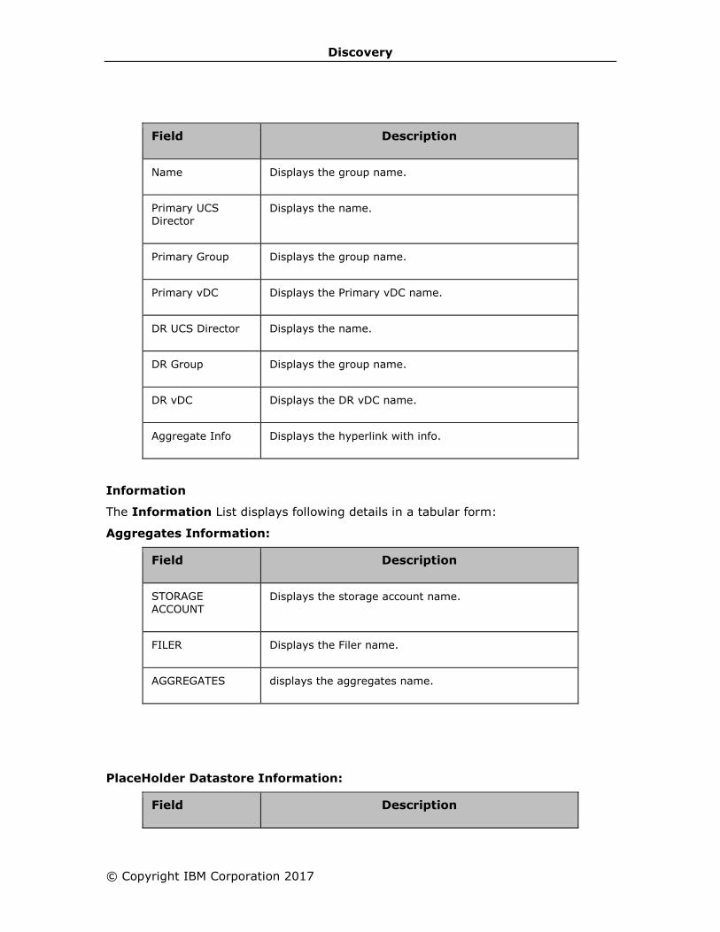
Discovery
© Copyright IBM Corporation 2017
Field Description
Name Displays the group name.
Primary UCS Director
Displays the name.
Primary Group Displays the group name.
Primary vDC Displays the Primary vDC name.
DR UCS Director Displays the name.
DR Group Displays the group name.
DR vDC Displays the DR vDC name.
Aggregate Info Displays the hyperlink with info.
Information
The Information List displays following details in a tabular form:
Aggregates Information:
Field Description
STORAGE ACCOUNT
Displays the storage account name.
FILER Displays the Filer name.
AGGREGATES displays the aggregates name.
PlaceHolder Datastore Information:
Field Description

IBM Resiliency Orchestration Administrator’s Guide
Field Description
PlaceHolder Datastore(s)
displays the Placeholder datastore's name.
1. Click Cancel to quit current operation.
Management Service
Adding Management Service
Click IBM Resiliency Orchestration Server User Role Management to see the
privileges.
To create a new Management service in the existing DR environment, perform the
following steps:
1. Click DISCOVER > Management Service on the navigation bar. The
Management Service List page appears with the following configured values.
▪ Name
▪ Type
▪ Site
▪ Status
2. Click the Add Management Service link at the top right corner of the
Management Service List page. The New Management Service page is
displayed.
▪ Configure the following field elements for Vcenter:
Field Description
SITE Select the site from the drop down list.
This field is mandatory.
MANAGEMENT SERVICE TYPE
Select the management service type from the drop-down list.
• VCENTER
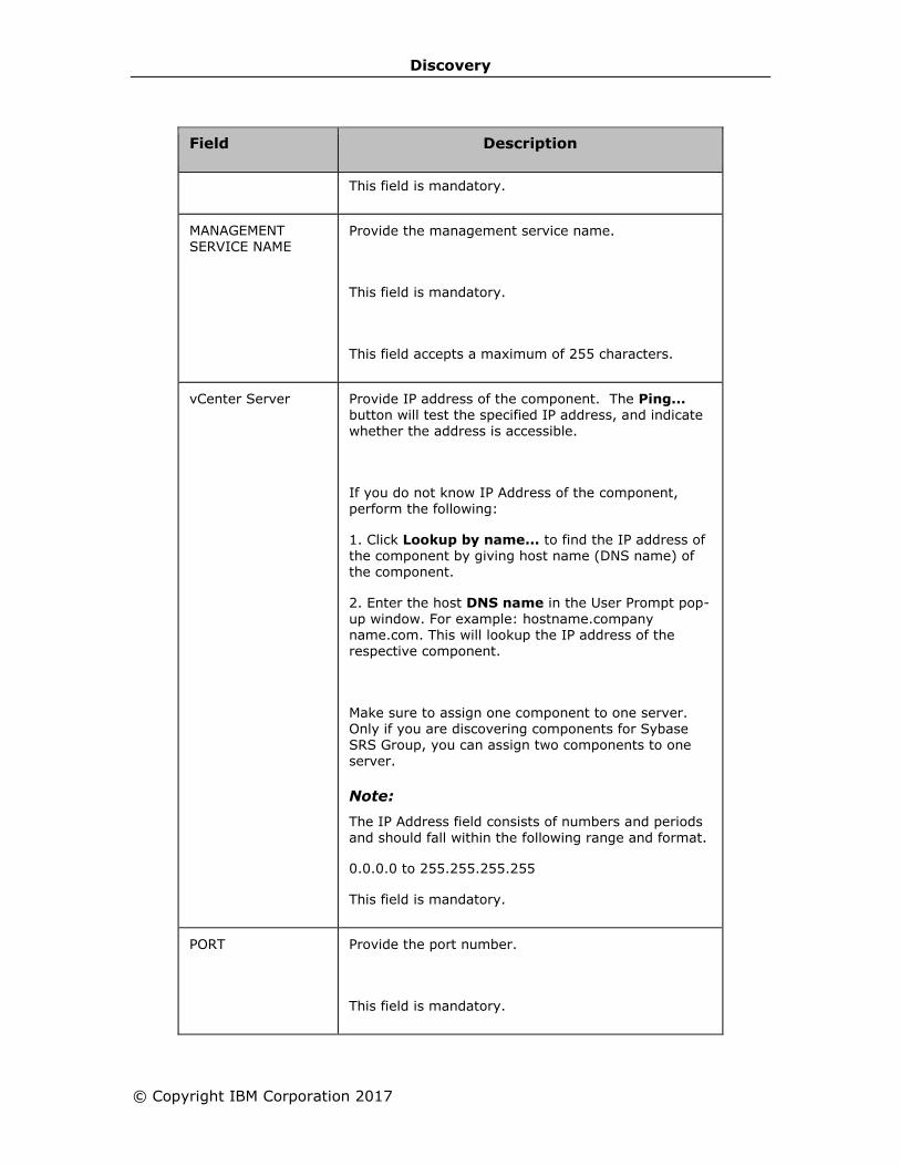
Discovery
© Copyright IBM Corporation 2017
Field Description
This field is mandatory.
MANAGEMENT SERVICE NAME
Provide the management service name.
This field is mandatory.
This field accepts a maximum of 255 characters.
vCenter Server Provide IP address of the component. The Ping... button will test the specified IP address, and indicate whether the address is accessible.
If you do not know IP Address of the component, perform the following:
1. Click Lookup by name... to find the IP address of the component by giving host name (DNS name) of the component.
2. Enter the host DNS name in the User Prompt pop-
up window. For example: hostname.company name.com. This will lookup the IP address of the respective component.
Make sure to assign one component to one server. Only if you are discovering components for Sybase SRS Group, you can assign two components to one server.
Note:
The IP Address field consists of numbers and periods and should fall within the following range and format.
0.0.0.0 to 255.255.255.255
This field is mandatory.
PORT Provide the port number.
This field is mandatory.

IBM Resiliency Orchestration Administrator’s Guide
Field Description
USER NAME Provide a unique name for the account being created.
Note:
This field accepts up to 32 alphanumeric characters, underscores. The name can start with an alphabet or a number.
This field is mandatory.
PASSWORD The password is used to authenticate the VCenter
user within IBM Resiliency Orchestration ™.
This field is mandatory.
This field accepts up to 16 alphanumeric characters including at least one digit.
Note:
The password cannot contain the character patterns listed below. The behaviour cannot be predicted if these are used:
▪ <script>(.*?)</script>
▪ Src=*
▪ Eval
▪ Expression
▪ JavaScript
▪ VBScript
▪ Onload
▪ Iframe
▪ <*>
Fetch from Vault This checkbox must be selected if you want the
vault software management system to serve the
password request.
Vault Name You must select the specific vault name from
the drop-down listbox. This will display input
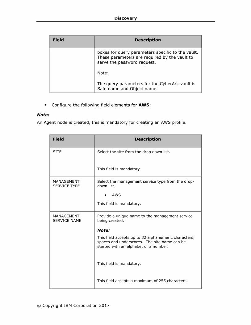
Discovery
© Copyright IBM Corporation 2017
Field Description
boxes for query parameters specific to the vault.
These parameters are required by the vault to
serve the password request.
Note:
The query parameters for the CyberArk vault is
Safe name and Object name.
▪ Configure the following field elements for AWS:
Note:
An Agent node is created, this is mandatory for creating an AWS profile.
Field Description
SITE Select the site from the drop down list.
This field is mandatory.
MANAGEMENT SERVICE TYPE
Select the management service type from the drop-down list.
• AWS
This field is mandatory.
MANAGEMENT SERVICE NAME
Provide a unique name to the management service being created.
Note:
This field accepts up to 32 alphanumeric characters,
spaces and underscores. The site name can be started with an alphabet or a number.
This field is mandatory.
This field accepts a maximum of 255 characters.
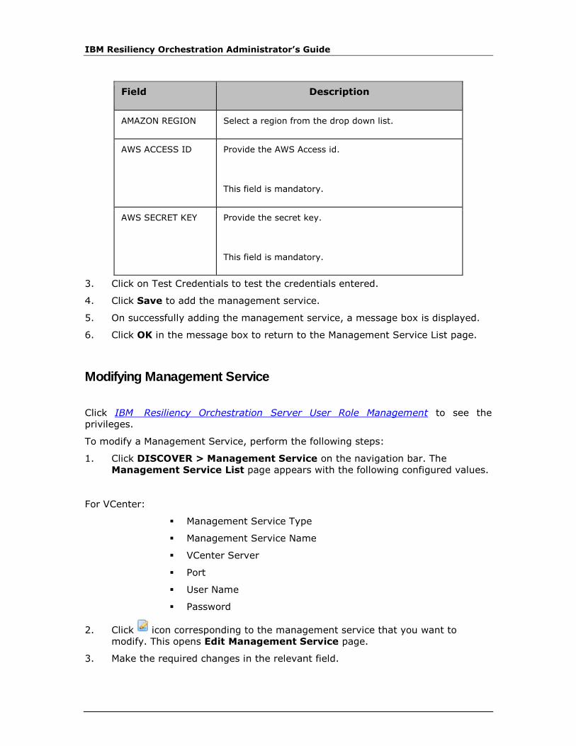
IBM Resiliency Orchestration Administrator’s Guide
Field Description
AMAZON REGION Select a region from the drop down list.
AWS ACCESS ID Provide the AWS Access id.
This field is mandatory.
AWS SECRET KEY Provide the secret key.
This field is mandatory.
3. Click on Test Credentials to test the credentials entered.
4. Click Save to add the management service.
5. On successfully adding the management service, a message box is displayed.
6. Click OK in the message box to return to the Management Service List page.
Modifying Management Service
Click IBM Resiliency Orchestration Server User Role Management to see the
privileges.
To modify a Management Service, perform the following steps:
1. Click DISCOVER > Management Service on the navigation bar. The
Management Service List page appears with the following configured values.
For VCenter:
▪ Management Service Type
▪ Management Service Name
▪ VCenter Server
▪ Port
▪ User Name
▪ Password
2. Click icon corresponding to the management service that you want to
modify. This opens Edit Management Service page.
3. Make the required changes in the relevant field.

Discovery
© Copyright IBM Corporation 2017
4. Click Save to save the modifications.
OR
Click Go Back to quit the current operation.
5. On successful modification, a message box is displayed.
6. Click OK in the message box to return to the Management Service List page.
For AWS:
1. Click DISCOVER > Management Service on the navigation bar. The
Management Service List page appears with the following configured values.
▪ Management Service Type
▪ Management Service Name
▪ Agent Node Component
▪ Aws region
▪ Aws Access Id
▪ Aws Secret key
2. Click icon corresponding to the management service that you want to
modify. This opens Edit Management Service page.
Note:
For AWS: Management service type,Management service name and Agent node
component cannot be modified.
Make the required changes in the relevant field.
3. Click Save to save the modifications.
OR
Click Go Back to quit the current operation.
4. On successful modification, a message box is displayed.
5. Click OK in the message box to return to the Management Service List page.
Deleting Management Service
Click IBM Resiliency Orchestration Server User Role Management to see the
privileges.
To delete a Management Service, perform the following steps:
1. Click DISCOVER > Management Service on the navigation bar. The
Management Service List page appears with the following configured values.
▪ Name
▪ Type
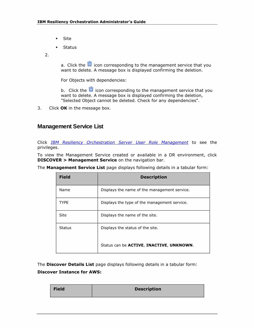
IBM Resiliency Orchestration Administrator’s Guide
▪ Site
▪ Status
2.
a. Click the icon corresponding to the management service that you
want to delete. A message box is displayed confirming the deletion.
For Objects with dependencies:
b. Click the icon corresponding to the management service that you
want to delete. A message box is displayed confirming the deletion,
"Selected Object cannot be deleted. Check for any dependencies".
3. Click OK in the message box.
Management Service List
Click IBM Resiliency Orchestration Server User Role Management to see the
privileges.
To view the Management Service created or available in a DR environment, click
DISCOVER > Management Service on the navigation bar.
The Management Service List page displays following details in a tabular form:
Field Description
Name Displays the name of the management service.
TYPE Displays the type of the management service.
Site Displays the name of the site.
Status Displays the status of the site.
Status can be ACTIVE, INACTIVE, UNKNOWN.
The Discover Details List page displays following details in a tabular form:
Discover Instance for AWS:
Field Description

Discovery
© Copyright IBM Corporation 2017
Field Description
Instance Name Displays the name of the AWS instance.
Instance ID Displays the id of the AWS instance.
Instance PRIVATE IP
Displays the name of the site.
1. Select the check box.
2. Click Save VM to save the AWS Instances.
3. On successfully adding the AWS instance, a message box is displayed.
4. Click OK in the message box to return to the Management Service List page.
Discover Images for AWS: Amazon machine images.
Field Description
AWS IMAGE Name Select the image
AWS IMAGE ID Enter the image id.
AWS IMAGE IP Enter the image ip.
1. Click Save image to save the image.
2. On successfully adding the AWS image , a message box is displayed.
3. Click OK in the message box to return to the Management Service List page.
SRA
SRA Discovery
Pre conditions before Provisioning
▪ PR - SRA site and VCentre management service should be the same.
▪ DR - SRA Site and AWS management service site should be the same.
▪ VCentre management service and AWS management service should be
discovered.
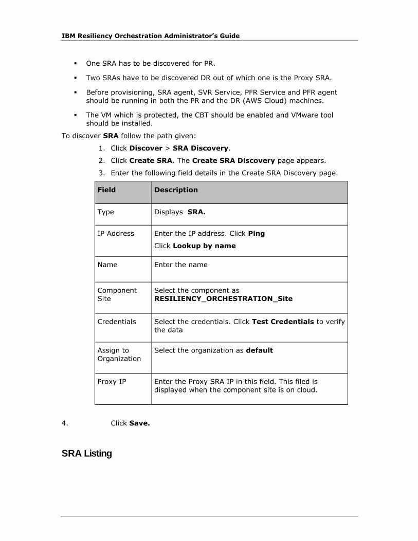
IBM Resiliency Orchestration Administrator’s Guide
▪ One SRA has to be discovered for PR.
▪ Two SRAs have to be discovered DR out of which one is the Proxy SRA.
▪ Before provisioning, SRA agent, SVR Service, PFR Service and PFR agent
should be running in both the PR and the DR (AWS Cloud) machines.
▪ The VM which is protected, the CBT should be enabled and VMware tool
should be installed.
To discover SRA follow the path given:
1. Click Discover > SRA Discovery.
2. Click Create SRA. The Create SRA Discovery page appears.
3. Enter the following field details in the Create SRA Discovery page.
Field Description
Type Displays SRA.
IP Address Enter the IP address. Click Ping
Click Lookup by name
Name Enter the name
Component
Site
Select the component as
RESILIENCY_ORCHESTRATION_Site
Credentials Select the credentials. Click Test Credentials to verify
the data
Assign to
Organization
Select the organization as default
Proxy IP Enter the Proxy SRA IP in this field. This filed is
displayed when the component site is on cloud.
4. Click Save.
SRA Listing
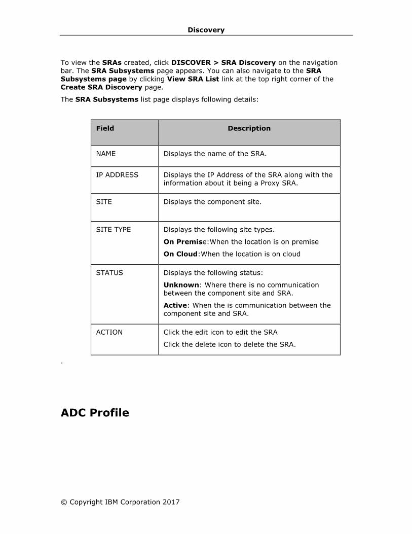
Discovery
© Copyright IBM Corporation 2017
To view the SRAs created, click DISCOVER > SRA Discovery on the navigation
bar. The SRA Subsystems page appears. You can also navigate to the SRA
Subsystems page by clicking View SRA List link at the top right corner of the
Create SRA Discovery page.
The SRA Subsystems list page displays following details:
Field Description
NAME Displays the name of the SRA.
IP ADDRESS Displays the IP Address of the SRA along with the
information about it being a Proxy SRA.
SITE Displays the component site.
SITE TYPE Displays the following site types.
On Premise:When the location is on premise
On Cloud:When the location is on cloud
STATUS Displays the following status:
Unknown: Where there is no communication
between the component site and SRA.
Active: When the is communication between the
component site and SRA.
ACTION Click the edit icon to edit the SRA
Click the delete icon to delete the SRA.
.
ADC Profile
IBM Resiliency Orchestration Administrator’s Guide
ADC is the new way of defining, deploying and managing application continuity in
cloud. ADC makes application’s continuity independent of the underlying
infrastructure. It allows the cloud applications to request for their continuity
requirements through policies to the cloud management platform and the ADC
intelligence built into the cloud management platform delivers the requested
continuity. ADC interfaces with the underlying infrastructure to enact application’s
recovery life-cycle. ADC will respond to the application’s changing continuity needs
and deliver by interfacing with the underlying infrastructure.
This chapter describes how to work with an ADC profile and explains the following:
Adding ADC profile
Modifying ADC profile
Deleting ADC profile
Listing ADC profile
Adding ADC Profile
Click IBM Resiliency Orchestration Server User Role Management to see the
privileges.
To create a new ADC profile in the existing Resiliency Orchestration environment,
perform the following steps:
1. Click DISCOVER > ADC Profile on the navigation bar. The ADC Profile List
appears with the following configured values.
▪ Name
▪ Allocation Type
▪ Allocation Percentage
▪ RPO (Minutes)
▪ Network
▪ Storage
2. Click the Add ADC Profile link at the top right corner of the ADC Profile List
page. The New ADC Profile page is displayed.
Configure the following field elements.
Field Description

Discovery
© Copyright IBM Corporation 2017
Field Description
NAME Provide a unique name to the service profile being created.
This field is mandatory.
Note:
This field accepts up to 32 alphanumeric characters, spaces and underscores. The Service profile name starts with an alphabet.
DESCRIPTION Provide the description for the service profile.
This field is mandatory.
ALLOCATION TYPE Select any one option from the drop-down list.
▪ Allocated
▪ Reserved
This field is mandatory.
ALLOCATION PERCENTAGE(25-100)
Provide the percentage to be allocated between 25-100.
This field is mandatory.
RPO (MINUTES) > 5 mins
Provide the time in minutes.
Note:
Time should be greater than 5 minutes.
This field is mandatory.
NETWORK Select the following option from the drop down list.
"Use UCS Director VDc Policy"

IBM Resiliency Orchestration Administrator’s Guide
Field Description
STORAGE Select the following option from the drop down list.
"Use UCS Director VDc Policy"
3. Click Save to add the ADC profile.
4. On successfully adding the ADC profile, a message box is displayed.
5. Click OK in the message box to return to the ADC profile List page.
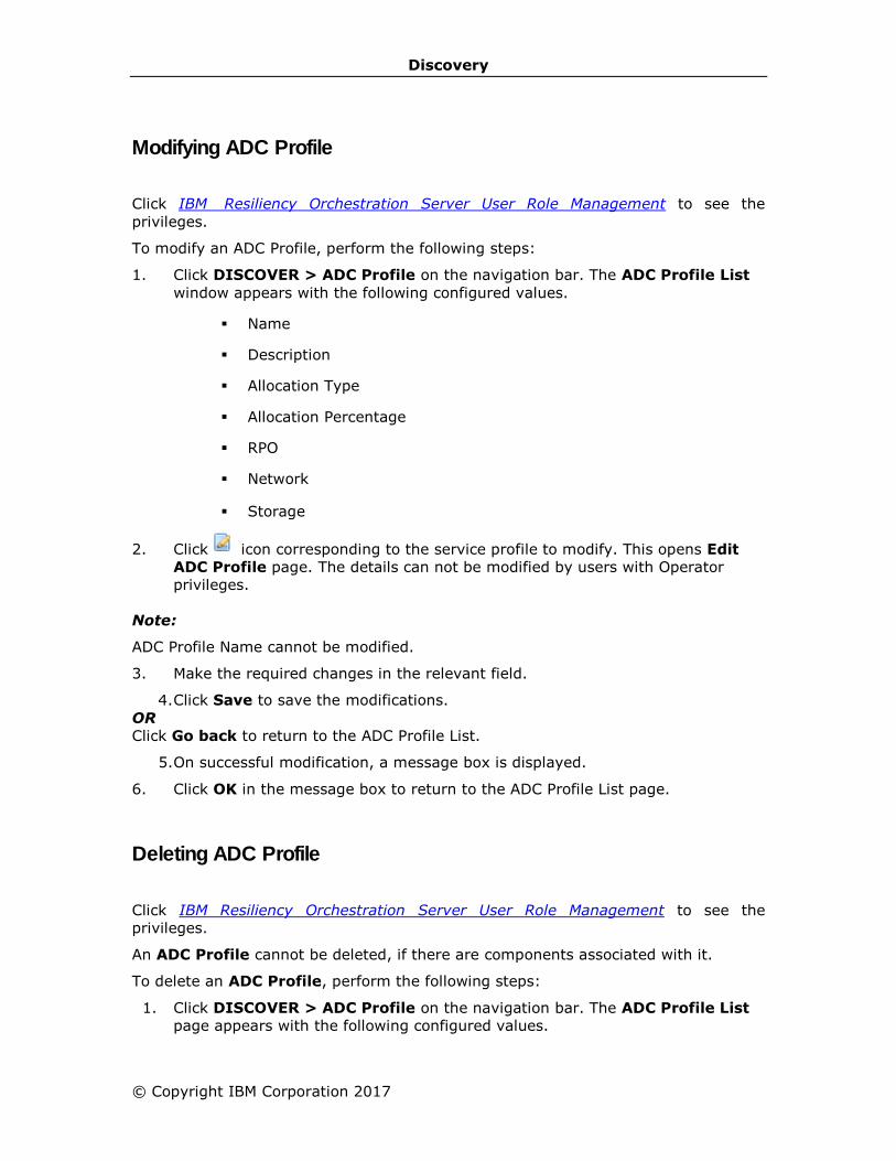
Discovery
© Copyright IBM Corporation 2017
Modifying ADC Profile
Click IBM Resiliency Orchestration Server User Role Management to see the
privileges.
To modify an ADC Profile, perform the following steps:
1. Click DISCOVER > ADC Profile on the navigation bar. The ADC Profile List
window appears with the following configured values.
▪ Name
▪ Description
▪ Allocation Type
▪ Allocation Percentage
▪ RPO
▪ Network
▪ Storage
2. Click icon corresponding to the service profile to modify. This opens Edit
ADC Profile page. The details can not be modified by users with Operator
privileges.
Note:
ADC Profile Name cannot be modified.
3. Make the required changes in the relevant field.
4. Click Save to save the modifications.
OR
Click Go back to return to the ADC Profile List.
5. On successful modification, a message box is displayed.
6. Click OK in the message box to return to the ADC Profile List page.
Deleting ADC Profile
Click IBM Resiliency Orchestration Server User Role Management to see the
privileges.
An ADC Profile cannot be deleted, if there are components associated with it.
To delete an ADC Profile, perform the following steps:
1. Click DISCOVER > ADC Profile on the navigation bar. The ADC Profile List
page appears with the following configured values.

IBM Resiliency Orchestration Administrator’s Guide
• Name
• Allocation Type
• Allocation Percentage
• RPO
• Network
• Storage
2. Click the icon corresponding to the ADC Profile that you want to delete. A
message box is displayed confirming the deletion.
3. Click OK in the message box.
Listing ADC Profile
Click IBM Resiliency Orchestration Server User Role Management to see the
privileges.
To view the ADC profile lists created or available in a IBM Resiliency Orchestration
environment, click DISCOVER > ADC Profile on the navigation bar.
The ADC Profile List page displays following details in a tabular form:
Field Description
Name Displays the name of the site.
ALLOCATION TYPE Displays the allocation name.
ALLOCATION PERCENTAGE
Displays the percentage allocated.
RPO Displays the RPO entered in minutes.
Note:
Time should be greater than 5 minutes.
This field is mandatory.
NETWORK Displays the type of network used.
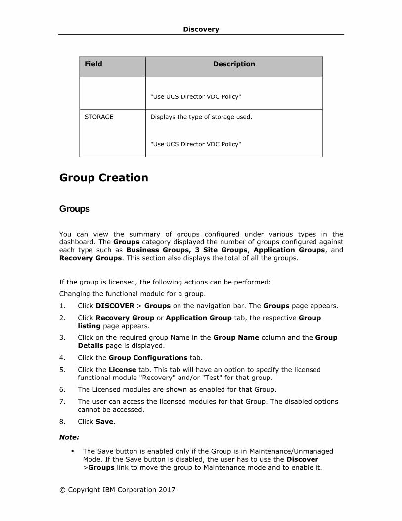
Discovery
© Copyright IBM Corporation 2017
Field Description
"Use UCS Director VDC Policy"
STORAGE Displays the type of storage used.
"Use UCS Director VDC Policy"
Group Creation
Groups
You can view the summary of groups configured under various types in the
dashboard. The Groups category displayed the number of groups configured against
each type such as Business Groups, 3 Site Groups, Application Groups, and
Recovery Groups. This section also displays the total of all the groups.
If the group is licensed, the following actions can be performed:
Changing the functional module for a group.
1. Click DISCOVER > Groups on the navigation bar. The Groups page appears.
2. Click Recovery Group or Application Group tab, the respective Group
listing page appears.
3. Click on the required group Name in the Group Name column and the Group
Details page is displayed.
4. Click the Group Configurations tab.
5. Click the License tab. This tab will have an option to specify the licensed
functional module "Recovery" and/or "Test" for that group.
6. The Licensed modules are shown as enabled for that Group.
7. The user can access the licensed modules for that Group. The disabled options
cannot be accessed.
8. Click Save.
Note:
▪ The Save button is enabled only if the Group is in Maintenance/Unmanaged
Mode. If the Save button is disabled, the user has to use the Discover
>Groups link to move the group to Maintenance mode and to enable it.

IBM Resiliency Orchestration Administrator’s Guide
▪ On clicking the Save button without any modules selected, a warning
message "At least one module has to be enabled for the group" is displayed.
▪ On clicking the Save button with one or more modules selected, the group will
be assigned with the selected modules and the user can perform any
functionality related to that module.
The IBM Resiliency Orchestration server will count the licenses appropriately as per
the modules checked by the user.
Specifying the functional module for a group during group creation
1. Click Save after creating the Group. The Group Configuration page is displayed.
2. Click the License tab. The tab displays options to specify the licensed functional
modules for that Group.
3. The licensed modules are enabled and the unlicensed modules are shown as
disabled.
Note:
The "Enable" button will be enabled only if the group is in “Maintenance/Unmanaged
mode”. For a newly created group, the "Enable" button will be shown as enabled.
▪ On clicking the "Enable" button without any modules selected, a warning
message "At least one module has to be enabled for the group" is displayed.
▪ On clicking the "Enable" button with one or more modules selected, the group
will be assigned with the selected modules and user can perform any
functionality related to that module.
The IBM Resiliency Orchestration server will count the licenses appropriately as per
the modules checked by the user.
Creating / Editing Groups
A Group is created / Edited by discovering Components, Datasets and Protection
Schemes and by associating them to a site. Refer Adding Sites and Discovering
Subsystem for more information.
Click IBM Resiliency Orchestration Server User Role Management to see the
privileges.
A Group is configured completely by performing following steps:
1. Group Details
2. Define Relationship
3. Provide Solution Details
4. Configure a Group
▪ Configure RPO/ RTO/ Data Lag Objective
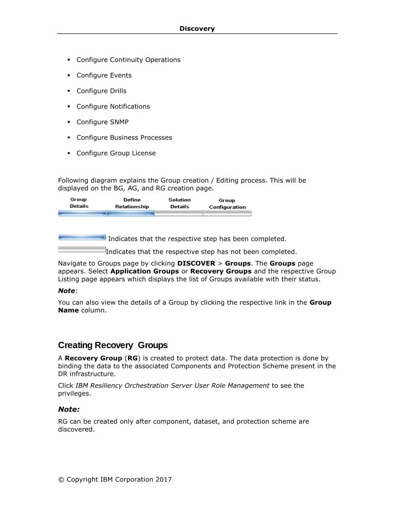
Discovery
© Copyright IBM Corporation 2017
▪ Configure Continuity Operations
▪ Configure Events
▪ Configure Drills
▪ Configure Notifications
▪ Configure SNMP
▪ Configure Business Processes
▪ Configure Group License
Following diagram explains the Group creation / Editing process. This will be
displayed on the BG, AG, and RG creation page.
Indicates that the respective step has been completed.
Indicates that the respective step has not been completed.
Navigate to Groups page by clicking DISCOVER > Groups. The Groups page
appears. Select Application Groups or Recovery Groups and the respective Group
Listing page appears which displays the list of Groups available with their status.
Note:
You can also view the details of a Group by clicking the respective link in the Group
Name column.
Creating Recovery Groups
A Recovery Group (RG) is created to protect data. The data protection is done by
binding the data to the associated Components and Protection Scheme present in the
DR infrastructure.
Click IBM Resiliency Orchestration Server User Role Management to see the
privileges.
Note:
RG can be created only after component, dataset, and protection scheme are
discovered.
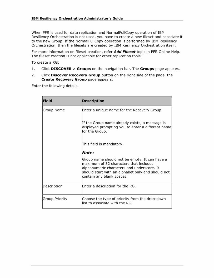
IBM Resiliency Orchestration Administrator’s Guide
When PFR is used for data replication and NormalFullCopy operation of IBM
Resiliency Orchestration is not used, you have to create a new fileset and associate it
to the new Group. If the NormalFullCopy operation is performed by IBM Resiliency
Orchestration, then the filesets are created by IBM Resiliency Orchestration itself.
For more information on fileset creation, refer Add Fileset topic in PFR Online Help.
The fileset creation is not applicable for other replication tools.
To create a RG:
1. Click DISCOVER > Groups on the navigation bar. The Groups page appears.
2. Click Discover Recovery Group button on the right side of the page, the
Create Recovery Group page appears.
Enter the following details.
Field Description
Group Name Enter a unique name for the Recovery Group.
If the Group name already exists, a message is
displayed prompting you to enter a different name
for the Group.
This field is mandatory.
Note:
Group name should not be empty. It can have a
maximum of 32 characters that includes
alphanumeric characters and underscore. It
should start with an alphabet only and should not
contain any blank spaces.
Description Enter a description for the RG.
Group Priority Choose the type of priority from the drop-down
list to associate with the RG.
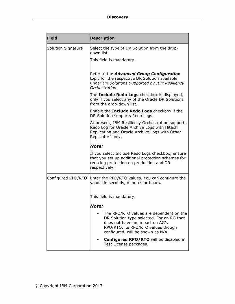
Discovery
© Copyright IBM Corporation 2017
Field Description
Solution Signature Select the type of DR Solution from the drop-
down list.
This field is mandatory.
Refer to the Advanced Group Configuration
topic for the respective DR Solution available
under DR Solutions Supported by IBM Resiliency
Orchestration.
The Include Redo Logs checkbox is displayed,
only if you select any of the Oracle DR Solutions
from the drop-down list.
Enable the Include Redo Logs checkbox if the
DR Solution supports Redo Logs.
At present, IBM Resiliency Orchestration supports
Redo Log for Oracle Archive Logs with Hitachi
Replication and Oracle Archive Logs with Other
Replicator” only.
Note:
If you select Include Redo Logs checkbox, ensure
that you set up additional protection schemes for
redo log protection on production and DR
respectively.
Configured RPO/RTO Enter the RPO/RTO values. You can configure the
values in seconds, minutes or hours.
This field is mandatory.
Note:
▪ The RPO/RTO values are dependent on the
DR Solution type selected. For an RG that
does not have an impact on AG’s
RPO/RTO, its RPO/RTO values though
configured, will be shown as N/A.
▪ Configured RPO/RTO will be disabled in
Test License packages.
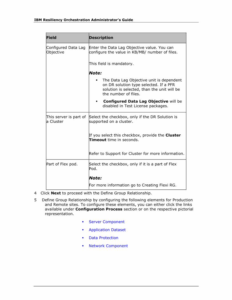
IBM Resiliency Orchestration Administrator’s Guide
Field Description
Configured Data Lag
Objective
Enter the Data Lag Objective value. You can
configure the value in KB/MB/ number of files.
This field is mandatory.
Note:
▪ The Data Lag Objective unit is dependent
on DR solution type selected. If a PFR
solution is selected, than the unit will be
the number of files.
▪ Configured Data Lag Objective will be
disabled in Test License packages.
This server is part of
a Cluster
Select the checkbox, only if the DR Solution is
supported on a cluster.
If you select this checkbox, provide the Cluster
Timeout time in seconds.
Refer to Support for Cluster for more information.
Part of Flex pod. Select the checkbox, only if it is a part of Flex
Pod.
Note:
For more information go to Creating Flexi RG.
4 Click Next to proceed with the Define Group Relationship.
5 Define Group Relationship by configuring the following elements for Production
and Remote sites. To configure these elements, you can either click the links
available under Configuration Process section or on the respective pictorial
representation.
▪ Server Component
▪ Application Dataset
▪ Data Protection
▪ Network Component
Discovery
© Copyright IBM Corporation 2017
Note:
▪ After defining each of the elements as mentioned above, the pictorial
representation of the respective icons becomes (tick mark icon) indicating that
the elements have been set up.
▪ At any point during group configuration, click Back to go back to the previous
page or click Cancel to abort the group configuration.
6 Click Next. A message box is displayed indicating the Group has been created
successfully.
7 If Group creation fails, "Group Details" page of the create group will be shown
with the error message.
8 Click OK to configure DR Solution specific details.
For specific information on this configuration, refer to respective pages under DR
Solutions Supported by IBM Resiliency Orchestration.
Perform any of the following:
▪ Click Save to create Recovery Group.
▪ Click Reset to set the previous values in the GUI.
▪ Click Cancel to quit the current window without saving changes.
Server Component
During the Group creation process, configure the server component.
To configure the server component, perform the following steps:
1. In the Create Recovery Group page, after entering the details for Group
Details, click Next.
2. In Define Relationship, click Server Component from the Configuration
Process section or click the icon. The Select Components window is
displayed. It displays the list of Primary and Remote components discovered
during component discovery.
3. Select the component for Primary and Remote sites by clicking the respective
check box from the Primary Components and Remote Components list.
You can select more than one component at a time.
4. Click Save to save the changes.
5. Click Close Window to close the window.
Note:
The components that you select on the Select Component window will be saved
and shown when you open this window next time.

IBM Resiliency Orchestration Administrator’s Guide
Application Dataset
During the Group creation process, after configuring the Server component, user
need to configure Application Dataset.
To configure the Application Dataset, perform the following steps:
1. In the Create Recovery Group page, after entering the details for Group
Details, click Next.
2. In Define Relationship, click Application Dataset from the Configuration
Process section or click the icon. The Select Datasets window is
displayed. It displays the list of components discovered during dataset
discovery on Primary and Remote sites for the respective solutions supported
by IBM Resiliency Orchestration.
3. Click the Show all datasets checkbox to display the datasets, even if these
are already in use.
4. Select the dataset for Primary and Remote sites by clicking the dataset from
the Primary Dataset and Remote Dataset lists. You can select only one
dataset for Primary and Remote sites at a time.
Note:
The Dataset is unique for a Group.
5. Click Save to save the changes.
6. Click Close Window to close the window.
Note:
The dataset(s) that you select on the Select Datasets window will be saved and
shown when you open this window next time.
Data Protection
To configure the data protection schemes, perform the following steps:
1. In the Create Recovery Group page, after entering the details for Group
Details, click Next.
2. In Define Relationship, Click Data Protection from the Configuration
Process section or click the icon. The Select Protection Schemes
window is displayed. It displays the list of components discovered during
protection scheme discovery on Primary and Remote sites for the respective
solutions supported by IBM Resiliency Orchestration.
3. Select the protection scheme for Primary and Remote sites by clicking the
protection scheme from the Primary Protection and Remote Protection
lists. You can select only one protection scheme for Primary and Remote sites

Discovery
© Copyright IBM Corporation 2017
at a time. If you do not find a Protection Scheme, abort the operation and
initiate discovery.
Note:
▪ Select at least one protection scheme from the list. The protection scheme
selection is not available for Oracle RAC with PFR solution as Oracle RAC itself
creates its own filesets based on the number of nodes configured.
▪ The Protection Scheme should not be used in more than one Group. If used,
replication might not happen for one or more Groups simultaneously.
▪ If you enable redo log protections for any of the following solutions, ensure
that you select additional protection schemes on primary and remote to
protect redo logs :
▪ Oracle Archive Logs with Veritas Volume Replicator
▪ Oracle Archive Logs with SRDF
▪ Oracle Archive Logs with Global Mirror
4. Click Save to save the changes.
5. Click Close Window to close the window.
Note:
The protection scheme(s) that you select on the Select Protection Schemes
window will be saved and shown when you open this window next time.
Viewing Recovery Group Details
You can view the Recovery Group Details by performing the following steps:
1. Click Discover on Navigation bar.
2. Click Groups on the Sub-navigation bar. The Groups window is displayed.
3. Click Recovery Group tab, the Recovery Group listing page appears.
4. Click any Recovery group in the Group Name column. The Recovery Group
Details window is displayed. This window provides the following tabs:
Group Details - Displays the following information:
▪ Name of the group
▪ Associated AG
▪ Brief description of the group
▪ Solution along with the type of replication selected for the group
▪ Configured RPO and RTO for the group along with the priority set for the
group.
IBM Resiliency Orchestration Administrator’s Guide
You can edit the group details by clicking the Edit Group button, if you have
administrator privileges.
▪ Relationship - Displays the names of the datasets and components
configured for the primary and the remote site with specific details about the
chosen protection mechanism. You can view and configure each subsystem by
clicking the corresponding subsystem icon on the pictorial representation of
the relationship between the different subsytems. This opens the Protection
Details, Dataset Details, or Component Details pane which displays the
list of configured components, datasets or protection scheme.
▪ Solution Details - Displays the solution specific information. For example, in
the case of Application subsystem with PFR solution this tab displays the
custom script location and the critical process (es) which are resulting in
‘Application Down’ status.
▪ Group Configuration - Displays the following options for group
configuration:
▪ Continuity- Displays the list of BCOs that can be performed on the group.
Click each BCO link to configure the Workflow of the operation and add
any custom action(s).
▪ RPO/ RTO- You can configure the RPO/ RTO values for the RG.
▪ Drills- Displays the drills that can be performed on the RG. Click each drill
to link to configure the different actions of the drills or to add custom
action(s).
▪ Events- Displays the Events/ Events page for the group. Click each event
ID to view the event details.
▪ SNMP- You can add a new SNMP Trap Forwarder or select from the
existing trap forwarder list for sending notifications to the RG.
You can also click the corresponding icon to modify the configured properties for
each continuity operation.
Editing Recovery Group
A Recovery group can be edited only when it is in UNMANAGED or MAINTENANCE
and in Normal Continuity mode. Group edit is not allowed during crashed states.
When in these modes, Discovery Groups page will show “Edit Group” icon
enabled/highlighted, disabled otherwise.
Click IBM Resiliency Orchestration Server User Role Management to see the
privileges.
To edit a RecoveryGroup (RG):
1. Click DISCOVER > Groups on the navigation bar. The Groups page appears.
2. Click Recovery Group tab, the Recovery Group listing page appears.
Discovery
© Copyright IBM Corporation 2017
3. Click on edit group icon for the group you want to edit. The Group Details
page will be shown.
Go to Changing Group to Maintenance Mode to enable the edit group option.
Field Description
Group Name The name of the group.
This field is not editable.
Description
Description of the RG.
This field is editable.
Solution Signature Type of DR Solution.
This field is not editable.
Configured RPO/RTO The RPO/RTO values. You can configure the
values in seconds, minutes or hours.
This field is editable.
Note:
The RPO/RTO values are dependent on the DR
Solution type selected. For an RG that does not
have an impact on AG’s RPO/RTO, its RPO/RTO
values though configured, will be shown as N/A.
Configured Data Lag
Objective
Enter the Data Lag Objective value. You can
configure the value in KB/MB/ number of files.
This field is editable.
Note:
▪ The Data Lag Objective unit is dependent
on DR solution type selected. If a PFR
solution is selected, than the unit will be
the number of files.
IBM Resiliency Orchestration Administrator’s Guide
Field Description
This server is part of
a Cluster
Shown selected if the DR Solution is supported on
a cluster. The configured cluster timeout will also
be displayed.
This field is editable.
Refer to Support for Cluster for more information.
4. Click Next to Define Group Relationship.
5. Define Group Relationship by configuring the following elements for Production
and Remote sites.
To configure these elements, you can either click the links available under
Configuration Process section or on the respective pictorial representation.
"Application Dataset" cannot be configured during edit group.
▪ Server Component
▪ Data Protection
▪ Network Component
Note:
At any point during group configuration, click Back to go back to the previous page
or click Cancel to abort the group configuration.
6. Click Next to configure DR Solution specific details.
For specific information on this configuration, refer to respective pages under DR
Solutions Supported by IBM Resiliency Orchestration book in this Help file.
If configuration fails, the "Group Details" page of the edit group will show an error
message.
7. Perform any of the following:
▪ Click Submit to edit Recovery Group.
Note:
When the Submit button is clicked, a dialog window appears stating that
certain workflows, such as NormalCopy, SwitchOver, SwitchBack etc. will
be moved to the Draft state and that these workflows will need to be
Discovery
© Copyright IBM Corporation 2017
published before executing them. Click OK to accept and click Cancel to
cancel this behavior.
▪ Click Reset to set the previous values in the GUI.
▪ Click Cancel to quit the current window without saving changes.
8. If more than one data protection pairs have been added to the group,the
workflows of the group needs to be reviewed and customized to handle all the
data protection pairs. The workflows that are pre-loaded/pre-packaged will
handle only one pair of the data protection. If the group is of the type MSSQL
Logs with PFR, Application SubSystem with PFR or Sybase Logs with PFR,
then the workflows have to be completely removed by importing a new
workflow XML and then needs to be customized.
Application Group Workflow Auto Generation
Application Group (AG) workflows are auto-generated based on the Recovery Group
(RG) dependency. A user should make sure that all RGs are in proper state, before
executing any of the workflows.
For example to start an AG level Fail-over, all the RGs under an AG should be in
“Normal Inactive” state.
Points to remember:
AG Workflow auto-generation uses pattern base on the RG dependency and triggers
one of the pre-defined RG workflow. User has to fill all those pre-defined RG
workflows for proper execution of BCOs like Switch-over, Switch-back or Fail-over
from AG. Requirement is that all the workflows are in “Published” state before
triggering any AG BCOs.
The pre-defined RG workflows are:
▪ StartAppPR
▪ StopAppPR
▪ StartAppDR
▪ StopAppDR
▪ RoleSwitchToPR
▪ RoleSwitchToDR
▪ Recovery
It is recommended not to edit the auto-generated workflows of AG.

IBM Resiliency Orchestration Administrator’s Guide
Network Component
To configure the network component, perform the following steps:
1. Click Network Component from the Configuration Process section or click
the icon. The Select Components window is displayed. It displays the
list of network components discovered during Component Discovery for Primary
and Remote sites.
2. Select the component for Primary and Remote sites by clicking the respective
checkbox from the Primary Components and Remote Components list. You
can select more than one component at a time.
3. Click Save to save the changes.
4. Click Close Window to close the window.
Note:
The components that you select on the Select Components window will be saved
and shown when you open this window next time.
Support for Cluster
IBM Resiliency Orchestration supports Active-Passive and Active-Active clustering.
Based on the type of clustering, its configuration differs. IBM Resiliency Orchestration
provides cluster support to the following solutions:
▪ Active - Passive Cluster Support
▪ MSSQL with PFR
Cluster support for MSSQL-PFR requires Cluster Timeout interval to be
configured at the time of Recovery Group creation. It also requires the
virtual IP to be specified in the IBMAgentGeneric.cfg file for the cluster
to work. The IP address must be specified against the parameter
PANACES_SQLAGENT_DBNODE_ADDRESS. This parameter must be
configured for MSSQL cluster. At the time of recovery after disaster,
PFRconfig.bat file must be run to fail over the continuity to the cluster
node. Automatic running of this file can be configured in the cluster.
▪ Oracle True Copy with Veritas Cluster Support (VCS)
Oracle True Copy being the block replication based solution requires
only Cluster Timeout interval to be set at the time of Recovery Group
creation. Groups must be configured with Virtual IP.
▪ Active - Active Cluster Support
▪ Oracle RAC

Discovery
© Copyright IBM Corporation 2017
While creating a Group, Oracle RAC cluster support requires the Node
and Dataset configuration to be done at Production and DR site.
Protection scheme is automatically detected.
Note:
To use IBM Resiliency Orchestration to support cluster, the replication volume must
be on shared device to avoid data loss. For example, for MSSQL and Sybase, the
volume/directory where the transactional logs are dumped by IBM Resiliency
Orchestration™ must be shared. For Oracle the archive log location must be on
shared storage.
Perform following steps to enable IBM Resiliency Orchestration to support Cluster. It
is assumed that you have already installed cluster software on all the nodes.
1. Install required agents on all the nodes in a cluster. Refer to IBM Resiliency
Orchestration Installation Guide for information on Agent installation.
2. Configure cluster software so that it starts communicating to IBM Resiliency
Orchestration agents during cluster fail-over. Ensure that configuration of
cluster software starts IBM Resiliency Orchestration agents after the underlying
software being managed by the agent is up and active.
3. If RG is part of the cluster, then refer to Creating Recovery Group for
configuring the group on a cluster.
4. If you are using PFR as protection mechanism, refer to PFR Online Help for
more information on configuring the cluster software.
Creating an Application Group
One or more Recovery Groups are grouped together to form an Application Group
(AG). An AG can be created after RG's creation or RGs can be added later by editing
the AG.
Note:
You can view only those AGs that are assigned to you, by assigning an AG to a user,
all RGs under an AG will be automatically assigned to the user.
To create an AG, perform the following steps:
1. Click DISCOVER > Groups on the navigation bar. The Groups page appears.
2. Select Application Group tab, the Application Group listing page appears.
3. Click Discover Application Group button on the right side of the page, the
Create Application Group page appears.
Enter the following details to create an Application Group.
Field Description
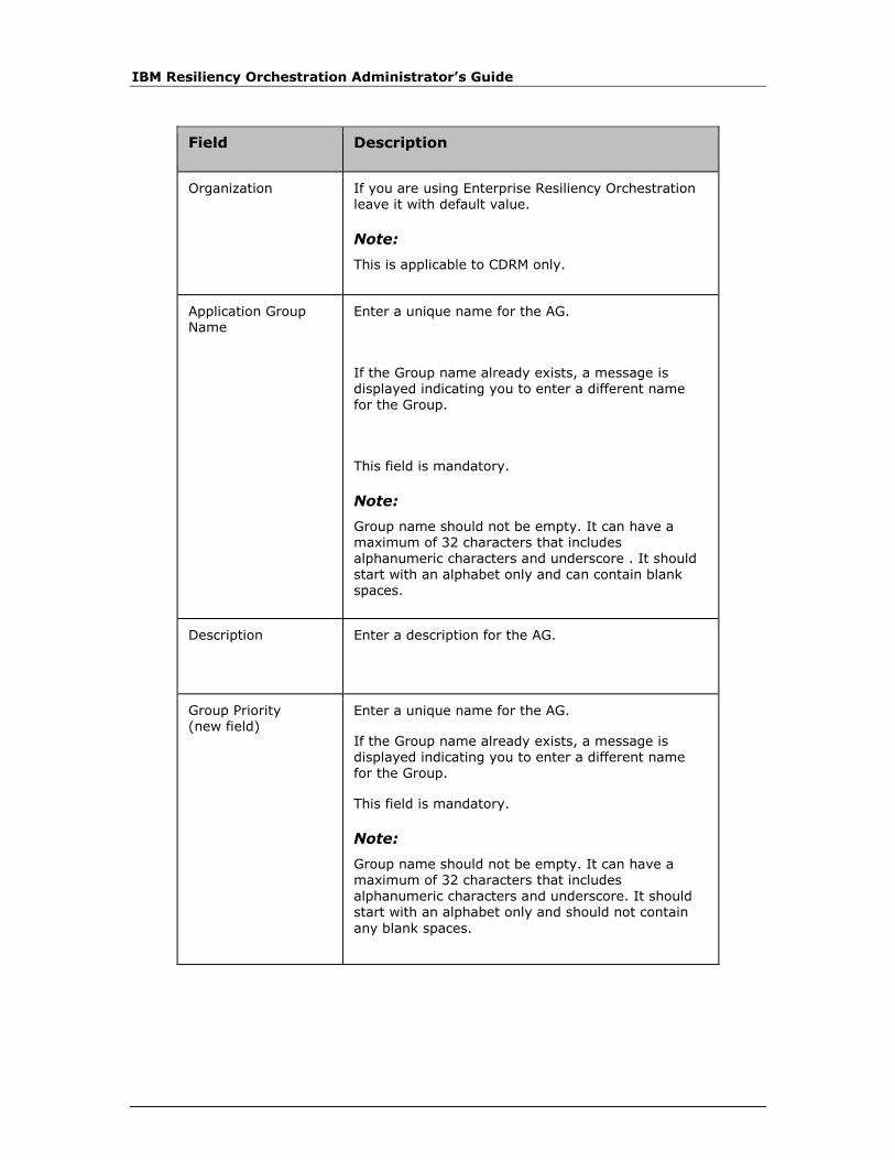
IBM Resiliency Orchestration Administrator’s Guide
Field Description
Organization If you are using Enterprise Resiliency Orchestration leave it with default value.
Note:
This is applicable to CDRM only.
Application Group Name
Enter a unique name for the AG.
If the Group name already exists, a message is displayed indicating you to enter a different name for the Group.
This field is mandatory.
Note:
Group name should not be empty. It can have a maximum of 32 characters that includes alphanumeric characters and underscore . It should start with an alphabet only and can contain blank spaces.
Description
Enter a description for the AG.
Group Priority (new field)
Enter a unique name for the AG.
If the Group name already exists, a message is displayed indicating you to enter a different name for the Group.
This field is mandatory.
Note:
Group name should not be empty. It can have a maximum of 32 characters that includes alphanumeric characters and underscore. It should start with an alphabet only and should not contain
any blank spaces.
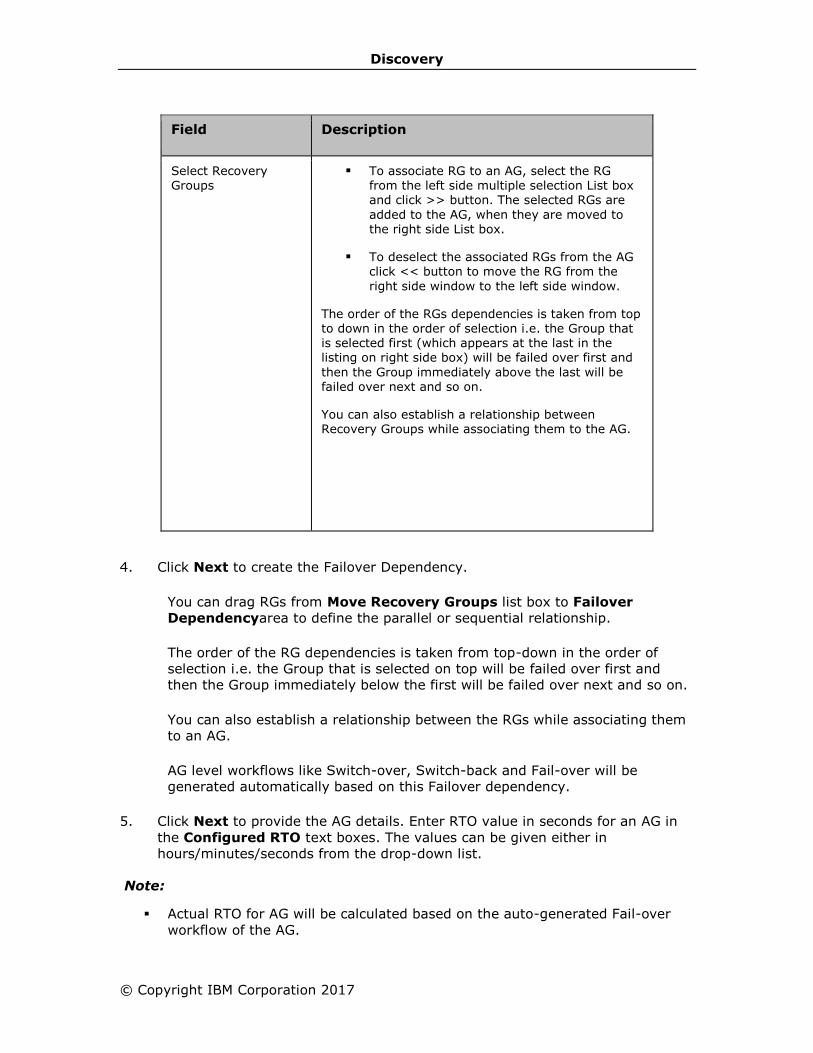
Discovery
© Copyright IBM Corporation 2017
Field Description
Select Recovery Groups
▪ To associate RG to an AG, select the RG from the left side multiple selection List box and click >> button. The selected RGs are
added to the AG, when they are moved to the right side List box.
▪ To deselect the associated RGs from the AG click << button to move the RG from the
right side window to the left side window.
The order of the RGs dependencies is taken from top to down in the order of selection i.e. the Group that
is selected first (which appears at the last in the listing on right side box) will be failed over first and
then the Group immediately above the last will be failed over next and so on.
You can also establish a relationship between Recovery Groups while associating them to the AG.
4. Click Next to create the Failover Dependency.
You can drag RGs from Move Recovery Groups list box to Failover
Dependencyarea to define the parallel or sequential relationship.
The order of the RG dependencies is taken from top-down in the order of
selection i.e. the Group that is selected on top will be failed over first and
then the Group immediately below the first will be failed over next and so on.
You can also establish a relationship between the RGs while associating them
to an AG.
AG level workflows like Switch-over, Switch-back and Fail-over will be
generated automatically based on this Failover dependency.
5. Click Next to provide the AG details. Enter RTO value in seconds for an AG in
the Configured RTO text boxes. The values can be given either in
hours/minutes/seconds from the drop-down list.
Note:
▪ Actual RTO for AG will be calculated based on the auto-generated Fail-over
workflow of the AG.

IBM Resiliency Orchestration Administrator’s Guide
▪ AG will support only RTO no RPO.
6. Perform any of the following:
▪ Click Back to go back to the previous page.
▪ Click Finish to save the changes.
▪ Click Cancel to quit the current operation.
Viewing Application Group details
You can view the Application Group Details by performing the following steps:
1. Click Discover on Navigation bar.
2. Click Groups on the Sub-navigation bar. The Groups window is displayed.
3. Click Application Group tab, the Application Group listing page appears.
4. Click any Application group in the Group Name column. The Application Group
Details window is displayed.
Editing Application Group
An application group can be edited only when it is in UNMANAGED or MAINTENANCE.
Click IBM Resiliency Orchestration Server User Role Management to see the
privileges.
To Edit a Application Group perform the following steps:
1. Click DISCOVER > Groups on the navigation bar. The Groups page appears.
2. Click Application Group tab, the Application Group listing page appears.
3. Click on edit group icon for the group you want to edit. The Group Details
page will be shown. The Group details cannot be modified by users with
Operator privileges.
Field Description
Organization The organization to which the AG
belongs.
This field is not editable.

Discovery
© Copyright IBM Corporation 2017
Field Description
Group Name The name of the group.
This field is not editable.
Description Description of the AG.
This field is editable.
Group Priority Select the type of priority from the
drop-down list.
Select Recovery Groups Recovery Groups can be added or
removed in this field.
Note:
You can edit AG only if AG is in Maintenance or Unmanaged mode.
4. Make the required changes in the relevant field.
5. Click Next to proceed with Create Failover Dependency page.
6. Click Next to proceed with Application Group Details page.
7. Click Back to go back to previous page.
8. Click Finish to save the changes.
9. Click Cancel to quit the current window without saving changes.
Deleting a Group
To delete a Group, it must meet the following criteria:
▪ It must be either in Unmanaged or Maintenance mode.
▪ It must not be associated with any other Group.
For the groups that do not meet above criteria, the Delete icon is disabled.
Click IBM Resiliency Orchestration Server User Role Management to see the
privileges.
The Groups created can be deleted by performing the following steps:
1. Click DISCOVER > Groups on the navigation bar. The Groups page appears.
2. Click Recovery Group or Application Group tab, the respective Group
listing page appears.
IBM Resiliency Orchestration Administrator’s Guide
3. Click icon corresponding to the Group that you want to delete. A message
box is displayed confirming the deletion.
Super Administrator has the privilege to create and delete a Group. Super
Administrator can delete any group (created by him or by other user
categories).
However, the Administrator can delete only those Groups that are
assigned to or created by him. When a Group is deleted, the fileset(s)
corresponding to the Group should also be deleted.
Note:
▪ You need at least one RG to retain an AG. If you delete the last RG then that
RG and its associated AG also gets deleted.
▪ You can delete AG only if it is in Maintenance or Unmanaged mode.
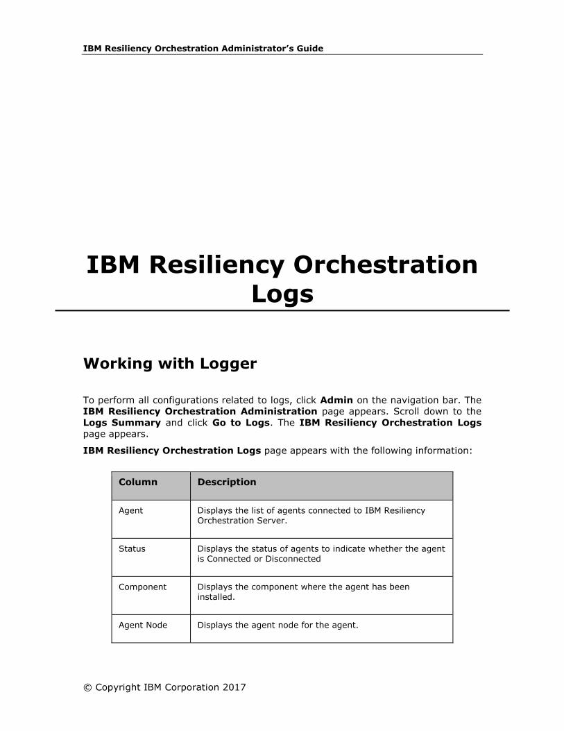
IBM Resiliency Orchestration Administrator’s Guide
© Copyright IBM Corporation 2017
IBM Resiliency Orchestration Logs
Working with Logger
To perform all configurations related to logs, click Admin on the navigation bar. The
IBM Resiliency Orchestration Administration page appears. Scroll down to the
Logs Summary and click Go to Logs. The IBM Resiliency Orchestration Logs
page appears.
IBM Resiliency Orchestration Logs page appears with the following information:
Column Description
Agent Displays the list of agents connected to IBM Resiliency Orchestration Server.
Status Displays the status of agents to indicate whether the agent is Connected or Disconnected
Component Displays the component where the agent has been installed.
Agent Node Displays the agent node for the agent.

IBM Resiliency Orchestration Administrator’s Guide
Column Description
Debug Level Provides the debug level drop-down list. You can see the debug level drop-down list only if the agent is connected
to IBM Resiliency Orchestration server. If the agent is not connected to IBM Resiliency Orchestration server, you see Unavailable in the Debug level column.
You can set the following preferences for log files on the right pane of IBM Resiliency
Orchestration Logs page:
▪ View the complete path of the log files stored on IBM Resiliency Orchestration
server in the Retrieved Logs will be stored on IBM Resiliency
Orchestration Server at the following location text box.
▪ Set the debug level for IBM Resiliency Orchestration server log by selecting
the debug levels from Server Debug Level Selection drop-down list. Refer
to Setting Debug Level for more information.
▪ Set IBM Resiliency Orchestration server and Agent Log Retention period.
Refer to Retaining Log for more information.
▪ Set the Server log file size limit on IBM Resiliency Orchestration server. Refer
to Setting Log File Size for more information.
Logger Overview
Logger maintains a periodic log of IBM Resiliency Orchestration operations. The log
files are created for the following modules of IBM Resiliency Orchestration:
▪ IBM Resiliency Orchestration GUI
▪ IBM Resiliency Orchestration Server
▪ Log file per Agent per Server
The naming format of the log file is a module name followed by that day's date with
'.log' as extension.
The logger has the following configurable options:
▪ Agent Debug Level
▪ IBM Resiliency Orchestration Server Debug Level Selection
▪ Server Log Retention Period
▪ Agent Log Retention Period
▪ Log File Size
You can also retrieve log files and filter log files by making specific choices.
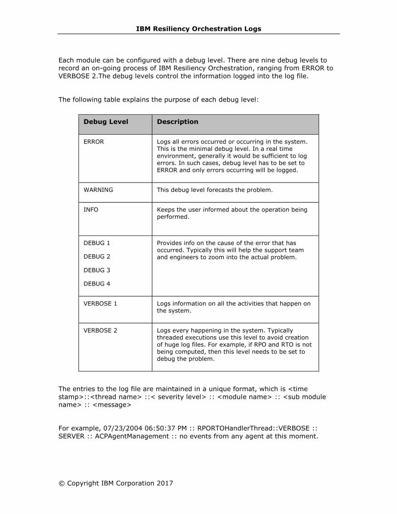
IBM Resiliency Orchestration Logs
© Copyright IBM Corporation 2017
Each module can be configured with a debug level. There are nine debug levels to
record an on-going process of IBM Resiliency Orchestration, ranging from ERROR to
VERBOSE 2.The debug levels control the information logged into the log file.
The following table explains the purpose of each debug level:
Debug Level Description
ERROR Logs all errors occurred or occurring in the system. This is the minimal debug level. In a real time environment, generally it would be sufficient to log
errors. In such cases, debug level has to be set to ERROR and only errors occurring will be logged.
WARNING This debug level forecasts the problem.
INFO
Keeps the user informed about the operation being performed.
DEBUG 1
DEBUG 2
DEBUG 3
DEBUG 4
Provides info on the cause of the error that has occurred. Typically this will help the support team and engineers to zoom into the actual problem.
VERBOSE 1 Logs information on all the activities that happen on the system.
VERBOSE 2 Logs every happening in the system. Typically threaded executions use this level to avoid creation of huge log files. For example, if RPO and RTO is not being computed, then this level needs to be set to debug the problem.
The entries to the log file are maintained in a unique format, which is <time
stamp>::<thread name> ::< severity level> :: <module name> :: <sub module
name> :: <message>
For example, 07/23/2004 06:50:37 PM :: RPORTOHandlerThread::VERBOSE ::
SERVER :: ACPAgentManagement :: no events from any agent at this moment.

IBM Resiliency Orchestration Administrator’s Guide
To perform all configurations related to logs, click Admin on the navigation bar. The
IBM Resiliency Orchestration Administration page appears. Scroll down to the
Logs Summary and click Go to Logs. The IBM Resiliency Orchestration Logs
page appears with the following information:
Column Description
Agent Displays the list of agents connected to IBM Resiliency Orchestration Server.
Status Displays the status of agents to indicate whether the agent is Connected or Disconnected
Component
Displays the component name where the agent has been installed.
AGENT NODE Displays the agent node of the agent.
Debug Level Provides the debug level drop-down list. You can see the debug level drop-down list only if the agent is connected to IBM Resiliency Orchestration server. If
the agent is not connected to IBM Resiliency
Orchestration server, you see Unavailable in the Debug level column.
You can set the following preferences for log files in the right pane of IBM Resiliency
Orchestration Logs page:
▪ View the complete path of the log files stored on the IBM Resiliency
Orchestration server in the Retrieved Logs will be stored on IBM
Resiliency Orchestration Server at the following location text box.
▪ Set the debug level for IBM Resiliency Orchestration server log by selecting
the debug levels from Server Debug Level Selection drop-down list. Refer
to Setting Debug Level for more information.
▪ Set IBM Resiliency Orchestration server and agent log retention period. Refer
to Retaining Log for more information.
▪ Set the log file size limit on IBM Resiliency Orchestration server. Refer to
Setting Log File Size for more information.
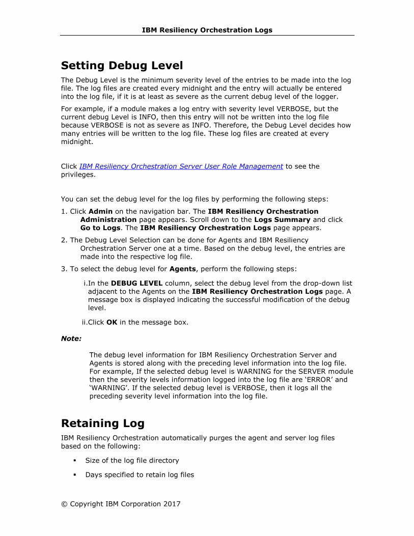
IBM Resiliency Orchestration Logs
© Copyright IBM Corporation 2017
Setting Debug Level
The Debug Level is the minimum severity level of the entries to be made into the log
file. The log files are created every midnight and the entry will actually be entered
into the log file, if it is at least as severe as the current debug level of the logger.
For example, if a module makes a log entry with severity level VERBOSE, but the
current debug Level is INFO, then this entry will not be written into the log file
because VERBOSE is not as severe as INFO. Therefore, the Debug Level decides how
many entries will be written to the log file. These log files are created at every
midnight.
Click IBM Resiliency Orchestration Server User Role Management to see the
privileges.
You can set the debug level for the log files by performing the following steps:
1. Click Admin on the navigation bar. The IBM Resiliency Orchestration
Administration page appears. Scroll down to the Logs Summary and click
Go to Logs. The IBM Resiliency Orchestration Logs page appears.
2. The Debug Level Selection can be done for Agents and IBM Resiliency
Orchestration Server one at a time. Based on the debug level, the entries are
made into the respective log file.
3. To select the debug level for Agents, perform the following steps:
i.In the DEBUG LEVEL column, select the debug level from the drop-down list
adjacent to the Agents on the IBM Resiliency Orchestration Logs page. A
message box is displayed indicating the successful modification of the debug
level.
ii.Click OK in the message box.
Note:
The debug level information for IBM Resiliency Orchestration Server and
Agents is stored along with the preceding level information into the log file.
For example, If the selected debug level is WARNING for the SERVER module
then the severity levels information logged into the log file are ‘ERROR’ and
‘WARNING’. If the selected debug level is VERBOSE, then it logs all the
preceding severity level information into the log file.
Retaining Log
IBM Resiliency Orchestration automatically purges the agent and server log files
based on the following:
▪ Size of the log file directory
▪ Days specified to retain log files
IBM Resiliency Orchestration Administrator’s Guide
As the log files are created every mid-night, they get accumulated and occupy the
server space. To free up the server space the old log files are deleted.
The log files are retained depending upon the retention period specified in ‘Days’ and
the log files are purged based on the size and the retention period.
In Days- Specifies the time period in number of days to retain the latest log files,
after which IBM Resiliency Orchestration deletes the oldest log files.
In size- Specifies the maximum size of the log file directory, where the IBM
Resiliency Orchestration server and agent log files reside. IBM Resiliency
Orchestration starts purging the oldest log files when the directory size exceeds the
maximum limit.
To know in detail about purging and retention of log files, consider the following
example:
Consider the following details:
Days – 5 (input)
Size – 100 MB (input)
Current Date – 12 Jan 2006
To purge and retain log files IBM Resiliency Orchestration, always considers the log
file older to the current date i.e. from the log file created on 11 Jan 2006 to the
oldest log file in the directory.
To purge the log file, IBM Resiliency Orchestration considers size as the primary
factor and the number of the days as the secondary factor. When the size of the log
file directory exceeds beyond 100 MB, IBM Resiliency Orchestration deletes the
oldest log file one by one till the directory size goes below 100 MB.
When the size of the log file directory is lesser than 100MB, then IBM Resiliency
Orchestration considers the number of days specified (i.e. 5) to retain the log files of
the past five days and to delete the oldest log file one by one in descending order.
Click IBM Resiliency Orchestration Server User Role Management to see the
privileges.
To select a log retention period, perform the following steps:

IBM Resiliency Orchestration Logs
© Copyright IBM Corporation 2017
1. Click Admin on the navigation bar. The IBM Resiliency Orchestration
Administration page appears. Scroll down to the Logs Summary and click
Go to Logs. The IBM Resiliency Orchestration Logs page appears.
On the right pane, set the Server Log Retention Period and Agent Log
Retention Period by performing the following steps under the respective
sections:
▪ Select Log Retention Period from the Days drop down list box. The
log retention period can be given only in number of days. The minimum
number of day is 1 and the maximum number of day is 30.
▪ Enter size of the log files in Mega Bytes (MB) in the Size field. The size
in MB is the threshold limit of the log file directory, beyond which the log
files are purged by IBM Resiliency Orchestration at a stipulated time
(usually at mid-night).
2. Click Save button.
Operational History
IBM Resiliency Orchestration server will automatically purge (delete) the metadata
and retain the required data for the retention period configured by the user. Data
available for reports is influenced by the metadata maintained by IBM Resiliency
Orchestration server.
Purging happens between 00:00 AM to 01:00 AM automatically based on the
configuration.
Click IBM Resiliency Orchestration Server User Role Management to see the
privileges.
To manage purging of the metadata, perform the following steps:
1. Click Admin on the navigation bar, the IBM Resiliency Orchestration
Administration page appears.
2. Scroll down to the Operational History Summary and click Go to
Operational History. The IBM Resiliency Orchestration Server
Operational History Management page appears. There are two tabs option:
▪ Purge Log Now
▪ Edit Log Retention Period
Purge Log Now
This tab shows the current retention period configured. The default values for the
Retention Period are given below:
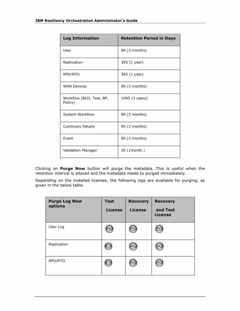
IBM Resiliency Orchestration Administrator’s Guide
Log Information Retention Period in Days
User 90 (3 months)
Replication 365 (1 year)
RPO/RTO 365 (1 year)
WAN Devices 90 (3 months)
Workflow (BCO, Test, BP, Policy)
1095 (3 years)
System Workflow 90 (3 months)
Continuity Details 90 (3 months)
Event 90 (3 months)
Validation Manager 30 (1month )
Clicking on Purge Now button will purge the metadata. This is useful when the
retention interval is altered and the metadata needs to purged immediately.
Depending on the installed licenses, the following logs are available for purging, as
given in the below table.
Purge Log Now
options
Test
License
Recovery
License
Recovery
and Test
License
User Log
Replication
RPO/RTO
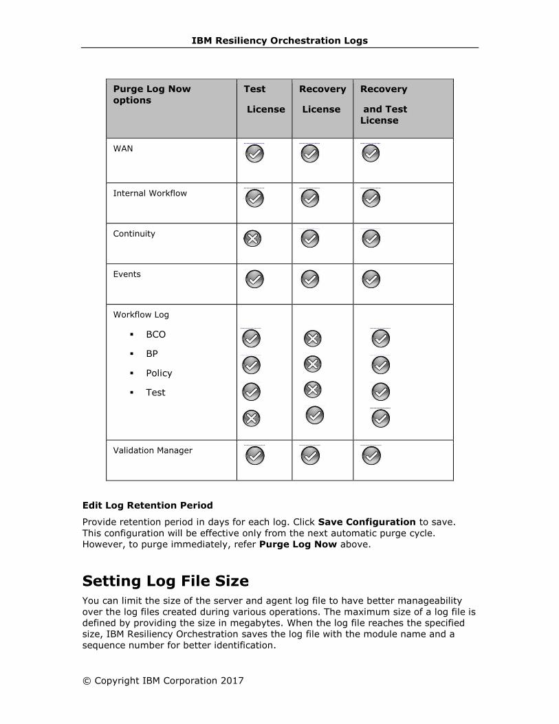
IBM Resiliency Orchestration Logs
© Copyright IBM Corporation 2017
Purge Log Now
options
Test
License
Recovery
License
Recovery
and Test
License
WAN
Internal Workflow
Continuity
Events
Workflow Log
▪ BCO
▪ BP
▪ Policy
▪ Test
Validation Manager
Edit Log Retention Period
Provide retention period in days for each log. Click Save Configuration to save.
This configuration will be effective only from the next automatic purge cycle.
However, to purge immediately, refer Purge Log Now above.
Setting Log File Size
You can limit the size of the server and agent log file to have better manageability
over the log files created during various operations. The maximum size of a log file is
defined by providing the size in megabytes. When the log file reaches the specified
size, IBM Resiliency Orchestration saves the log file with the module name and a
sequence number for better identification.
IBM Resiliency Orchestration Administrator’s Guide
The file naming convention is shown below:
Format: Module NameDateHH:MM_Sequence number.Log
For example:PanacesServer07-23-0404:55_1.log
PanacesServer07-23-0404:55_2.log
These log files are saved under a directory and are purged or retained on providing
retention period and size of the directory on the Log Retention page.
For more information on this refer to ‘Log Retention Period’ section in this guide.
Click IBM Resiliency Orchestration Server User Role Management to see the
privileges.
To set Log File Size, perform the following:
1. Click Admin on the navigation bar. The IBM Resiliency Orchestration
Administration page appears. Scroll down to the Logs Summary and click
Go to Logs. The IBM Resiliency Orchestration Logs page appears.
2. In the right pane, enter the Limit in Mega Bytes (MB) in the Log File Size
Limit area. When the size of the log file exceeds the specified limit, IBM
Resiliency Orchestration saves the log file and provides a sequence number.
The sequence number is used to refer to the log file.
3. Click Save. A message box is displayed.
4. Click OK in the message box.
Fetching Log Files
This option allows you to retrieve a log file from a corresponding site to IBM
Resiliency Orchestration Server.
Click IBM Resiliency Orchestration Server User Role Management to see the
privileges.
To retrieve a log file, perform the following steps:

IBM Resiliency Orchestration Logs
© Copyright IBM Corporation 2017
1. Click Admin on the navigation bar. The IBM Resiliency Orchestration
Administration page appears. Scroll down to the Logs Summary and click
Go to Logs. The IBM Resiliency Orchestration Logs page appears. Click the
Fetch Logs tab.
2. Provide the necessary inputs for the following fields:
Field Description
For Select the group from the drop-down list for which you want to fetch logs.
get logs for last Select the time duration in hours for which you want to fetch the logs.
3. Click the Fetch Log button. This opens a dialog box on windows to save the
log file.
Note:
To learn how to fetch log files using IBM Resiliency Orchestration command line tool,
see Fetching Log files using Resiliency Orchestration log CLI tool.
Note:
When the panaces is running with non-root, the system logs will not be fetched until
read permission is granted for the non-root user. The non-root user, by default, does
not have read permission for the system logs (/var/log/messages etc.).
System Capture
This option allows you to capture and view system details corresponding to IBM
Resiliency Orchestration Server.
To retrieve a log file, perform the following steps:
1. Click Admin on the navigation bar. The IBM Resiliency Orchestration
Administration page appears. Scroll down to the Logs Summary and click
Go to Logs. The IBM Resiliency Orchestration Logs page appears. Click the
System Capture tab.
2. Provide the necessary inputs for the following fields:
Field Description
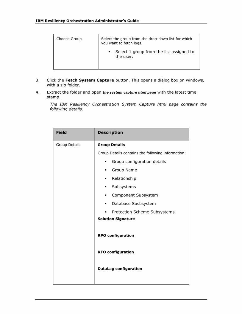
IBM Resiliency Orchestration Administrator’s Guide
Choose Group Select the group from the drop-down list for which you want to fetch logs.
▪ Select 1 group from the list assigned to
the user.
3. Click the Fetch System Capture button. This opens a dialog box on windows,
with a zip folder.
4. Extract the folder and open the system capture html page with the latest time
stamp.
The IBM Resiliency Orchestration System Capture html page contains the
following details:
Field Description
Group Details Group Details
Group Details contains the following information:
▪ Group configuration details
▪ Group Name
▪ Relationship
▪ Subsystems
▪ Component Subsystem
▪ Database Susbsystem
▪ Protection Scheme Subsystems
Solution Signature
RPO configuration
RTO configuration
DataLag configuration

IBM Resiliency Orchestration Logs
© Copyright IBM Corporation 2017
Field Description
Private details( This provides the replication details of the group)
Notifications
Notifications contains the following information:
▪ Notification list
▪ BCO
Test Exercises
Test Exercises contains the following information:
▪ Test Name, its description and the
test schedule in a tabular column.
Business Process Integration
Business Process Integration contains the
following information:
▪ Business Process Name, Business
Process Description, Frequncy and
Schedule in a tabular column.
Events:
Events contains the following information:
▪ Event Name, Event Description,
Event Severity, Notification Status,
and Event Impact in a tabular
column.
License details:
License details contains the following
information:
Modular Name, Enabled in a tabular column.
Active Workflows:
Active Workflows details contains the following information:
Current Workflow name, Status, Start time in a tabular column.

IBM Resiliency Orchestration Administrator’s Guide
Field Description
Continuity Details
Agent List
Listing Log Files
Click IBM Resiliency Orchestration Server User Role Management to see the
privileges.
To list the log files, perform the following steps:
1. Click Tools menu.
2. Click Logs.
3. Select Operations. The User Operations window is displayed.
This window displays the log files for all the actions performed. The operations
search is based on the following:
▪ Timestamp
▪ Object
▪ Status
These options are used to optimize the search and are not mandatory. The operation
performed so far can be retrieved irrespective of the search options by clicking the
All operations button present at the bottom of left frame.
To retrieve the operations performed based on timestamp, perform the following:
1. Click the Timestamp radio button in the left frame of the window.
2. Enter From and To timestamp in Select Timestamp & enter data in 2004-
12-21 10:42:12.0’ format fields in the format specified.
3. When any one of the option is selected, the search button at the bottom of the
left frame gets activated.
4. Click Search to search the operations based on the selected option.
Note:

IBM Resiliency Orchestration Logs
© Copyright IBM Corporation 2017
All three options (Timestamp, Objects and Status) cannot be selected at a time.
The following table lists the details of an operation:
Field Description
Time This gives the exact time of the operation.
Module This gives the name of the module on which the operation has been performed.
Object This gives the name of the object on which the operation has been performed.
Operation The gives the name of the operation performed.
Status The status of the performed operation is given here.
Description This field describes the operation.
To retrieve the information of the FAILED operations, perform the following steps:
1. Click the Status radio button on the left frame.
2. Enter the status of the operation in Select Status & enter status field.
3. Click the Search button to retrieve the operation based on the specified status.
This retrieves the ‘Failed’ operations.
To view the operations performed on a specific object, perform the following:
1. Click the Object radio button in the left frame.
2. Enter the name of the object in Select Object & enter object name field.
3. Click the Search button to retrieve the required information. This retrieves the
user operations performed on that particular object.
4. If you click the All Operations button, the User Operations window displays
log details of all the operations.
Filtering Log Files and Advanced Log Fetching
The log file fetching can be narrowed down by specifying date/time period (both start
date/time and end date/time) of the log occurrence and Log Source.
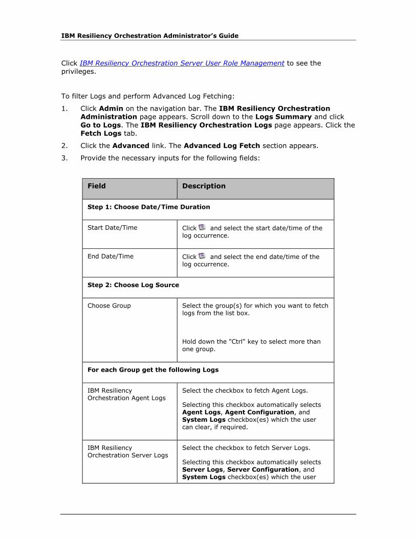
IBM Resiliency Orchestration Administrator’s Guide
Click IBM Resiliency Orchestration Server User Role Management to see the
privileges.
To filter Logs and perform Advanced Log Fetching:
1. Click Admin on the navigation bar. The IBM Resiliency Orchestration
Administration page appears. Scroll down to the Logs Summary and click
Go to Logs. The IBM Resiliency Orchestration Logs page appears. Click the
Fetch Logs tab.
2. Click the Advanced link. The Advanced Log Fetch section appears.
3. Provide the necessary inputs for the following fields:
Field Description
Step 1: Choose Date/Time Duration
Start Date/Time Click and select the start date/time of the log occurrence.
End Date/Time Click and select the end date/time of the log occurrence.
Step 2: Choose Log Source
Choose Group Select the group(s) for which you want to fetch logs from the list box.
Hold down the "Ctrl" key to select more than one group.
For each Group get the following Logs
IBM Resiliency
Orchestration Agent Logs
Select the checkbox to fetch Agent Logs.
Selecting this checkbox automatically selects Agent Logs, Agent Configuration, and System Logs checkbox(es) which the user can clear, if required.
IBM Resiliency Orchestration Server Logs
Select the checkbox to fetch Server Logs.
Selecting this checkbox automatically selects Server Logs, Server Configuration, and System Logs checkbox(es) which the user
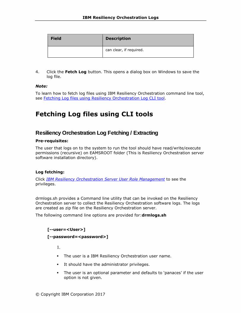
IBM Resiliency Orchestration Logs
© Copyright IBM Corporation 2017
Field Description
can clear, if required.
4. Click the Fetch Log button. This opens a dialog box on Windows to save the
log file.
Note:
To learn how to fetch log files using IBM Resiliency Orchestration command line tool,
see Fetching Log files using Resiliency Orchestration Log CLI tool.
Fetching Log files using CLI tools
Resiliency Orchestration Log Fetching / Extracting
Pre-requisites:
The user that logs on to the system to run the tool should have read/write/execute
permissions (recursive) on EAMSROOT folder (This is Resiliency Orchestration server
software installation directory).
Log fetching:
Click IBM Resiliency Orchestration Server User Role Management to see the
privileges.
drmlogs.sh provides a Command line utility that can be invoked on the Resiliency
Orchestration server to collect the Resiliency Orchestration software logs. The logs
are created as zip file on the Resiliency Orchestration server.
The following command line options are provided for:drmlogs.sh
[--user=<User>]
[--password=<password>]
1.
▪ The user is a IBM Resiliency Orchestration user name.
▪ It should have the administrator privileges.
▪ The user is an optional parameter and defaults to ‘panaces’ if the user
option is not given.

IBM Resiliency Orchestration Administrator’s Guide
▪ The password is an optional parameter and it prompts for password, if
password option is not given.
{ <--time =dd/mm/yyyy,hh:mm , --duration=N > }
1.
▪ Logs from time given as --time option and up to duration of 'N hours'
are collected (provided both are given).
▪ If duration option is not given, it means logs from –-time to current
time.
▪ If only --duration option is given, it means last 'N hours’ of logs from
current time.
▪ One of --time and --duration option must be provided.
▪ The time is taken as local time of the server from where the logs are
collected. If there is a time drift between the Resiliency Orchestration
server and the agents, then the logs collected may not be consistent
between the server logs and the agent logs.
[--server=[logs] [,config] [,system]]
[--server-other=<comma separated file paths>]
[--agent=[logs] [,config] [,system]]
[--agent-other=<comma separated file paths>]
1.
▪ --server and –-agents options specify the list of information to be
collected from the Resiliency Orchestration server and the agents
systems. The list of information to be collected is specified as comma
separated values.
▪ ‘logs’ keyword specifies IBM Resiliency Orchestration logs to be
collected. These are files under DRMROOT/var/log/*,
DRMROOT/panacesFileReplicator/filesets/*
▪ ‘config’ keyword specifies IBM Resiliency Orchestration configuration
files. These are files under DRMROOT/installconfig/*.
▪ --server-other and –-agent-other option is any arbitrary file. Full file
path needs to be given. This file will be retrieved only if the user has
permission to that file.
▪ If none of the server and agent option is given, it defaults to agent and
server logs.
[--group =<group name> [--c] [--d] [--p]]
[--component =<cname1>[,<cname2]*]
[--dataset =<datasetname>[,<datasetname>]*

IBM Resiliency Orchestration Logs
© Copyright IBM Corporation 2017
[--protection =<protectionScheme> [,<protectionScheme>]*
▪ Either –group or combination of -component,-dataset,-protection
needs to be provided.
▪ Group option specify group name for which to collect logs. This should
be a functional group and cannot be an application group. If specified
that a group name does not exist, then an appropriate message is
shown.
▪ If no other option [like --c or --d or --p] is present, then for the given
group, all the logs of dependent subsystem are collected. Dependent
subsystem include dataset/protection/component from both primary
and dr site. If –c, --d or -–p options are given, only components or
dataset or protection, depending on an option given, would be
retrieved.
▪ --component, --dataset, --protection specifies comma separated list
of names for which to collect log files.
--filename <filename>
▪ Filename is the name of the output file. The filename should be a
complete path name, otherwise it is the current directory. If this
option is not given, a file is generated in $EAMSROOT/var/log. The
name of the generated file will be displayed as “<user-
name>_IBMLogs-uniqueNumber.zip."
Extracting logs:
drmlogs.sh can also be used to extract the log files from zipped log file, when files
cannot be extracted using other unzip utilities. This utility can extract archive files up
to 4GB size created by IBM log fetcher only. The utility is supported for RHEL Version
5 UNIX (and later versions) running Java Runtime Environment 1.5 (and later
versions).
This can be invoked as follows:
$EAMSROOT/bin/drmlogs.sh {--extract=<absolute-path-of-zip-file> --
destination=<destination-dir>} [--buffer-size=<N-bytes>]
The placement of the command line parameters should exactly match as per the CLI
usage presented above i.e. The user can use this CLI with the following commands
only (e.g.):
▪ $EAMSROOT/bin/drmlogs.sh --extract=/opt/mycreatedzipfile.zip --
destination=/opt/zipcontent
▪ $EAMSROOT/bin/drmlogs.sh --extract=/opt/mycreatedzipfile.zip --
destination=/opt/zipcontent --buffer-size=10000

IBM Resiliency Orchestration Administrator’s Guide
Any other format of the CLI will not extract the zip file and will be considered for
fetching Resiliency Orchestration logs. Following options are provided.
--extract:
The value should be the absolute path of the zip file which needs to be
extracted. The command invoking user should have the required
permissions to open the file. This is a mandatory parameter.
--destination-dir:
The value should be the absolute path of the directory to which the
extracted files have to be written. The command invoking the user
should have the required permissions to create, open, read and write
files and directories in this directory recursively. This is a mandatory
parameter.
--buffer-size:
The value should be a positive integer between 1 and 33554432 (i.e.
32MB). This is an optional parameter. This is the size of page
read/written during extraction of the zip file. In the event of user not
specifying the option, the default 2MB buffer is used. User specifying a
value greater than 32MB, a buffer size of 32MB will be used. Any invalid
value defaults to 2MB. (Note: This is a performance tuning parameter
and should be used with care).
IBM Resiliency Orchestration Logs
© Copyright IBM Corporation 2017
Resiliency Orchestration Log Admin
drmlogadmin.sh
Log collection CLI can be used to retrieve any files from the customer server as long
as the user with which the agent is running has privilege to access those files. To
give control to the user to determine which files outside of Resiliency Orchestration
Installation folder, is allowed to be retrieved by log collection tool, an admin tool is
provided. Using admin cli, the user can enable or disable certain path or the ability to
collect system log files. By default, only collection of system logs (like
/var/log/message on linux or oracle alert logs etc) are enabled that are outside of
Resiliency Orchestration Installation folder. Any other files outside of Resiliency
Orchestration Installation folder cannot be accessed until user adds the paths.
Click IBM Resiliency Orchestration Server User Role Management to see the
privileges.
The following command line options are provided:
[--user <User>]
[--password <password>]
▪ The user is a Resiliency Orchestration user name.
▪ It should have Super administrator privileges.
▪ The user is an optional parameter and defaults to ‘panaces’ if user
option is not given.
▪ The password is an optional parameter and it prompts for password, if
password option is not given.
[--list ]
▪ Lists the current configuration. It lists the files or logs that are allowed
to be collected. By default system log files are allowed.
[ --add-file=CompName:FilePath [, CompName2:FilePath2].. ]
Value of this option is a list of comma separated string of
“CompName:FilePath1”. CompName is name of component where the file
path “FilePath1” is allowed to be accessed by log cli.
[--add=system_logs]
To add allowing collection of system log. By default this is enabled.
[--remove-file= CompName:FilePath [, CompName2:FilePath2].. ]
Removing file path from the list of allowed file paths.

IBM Resiliency Orchestration Administrator’s Guide
[--remove=system_logs ]
Removing collection of system logs.
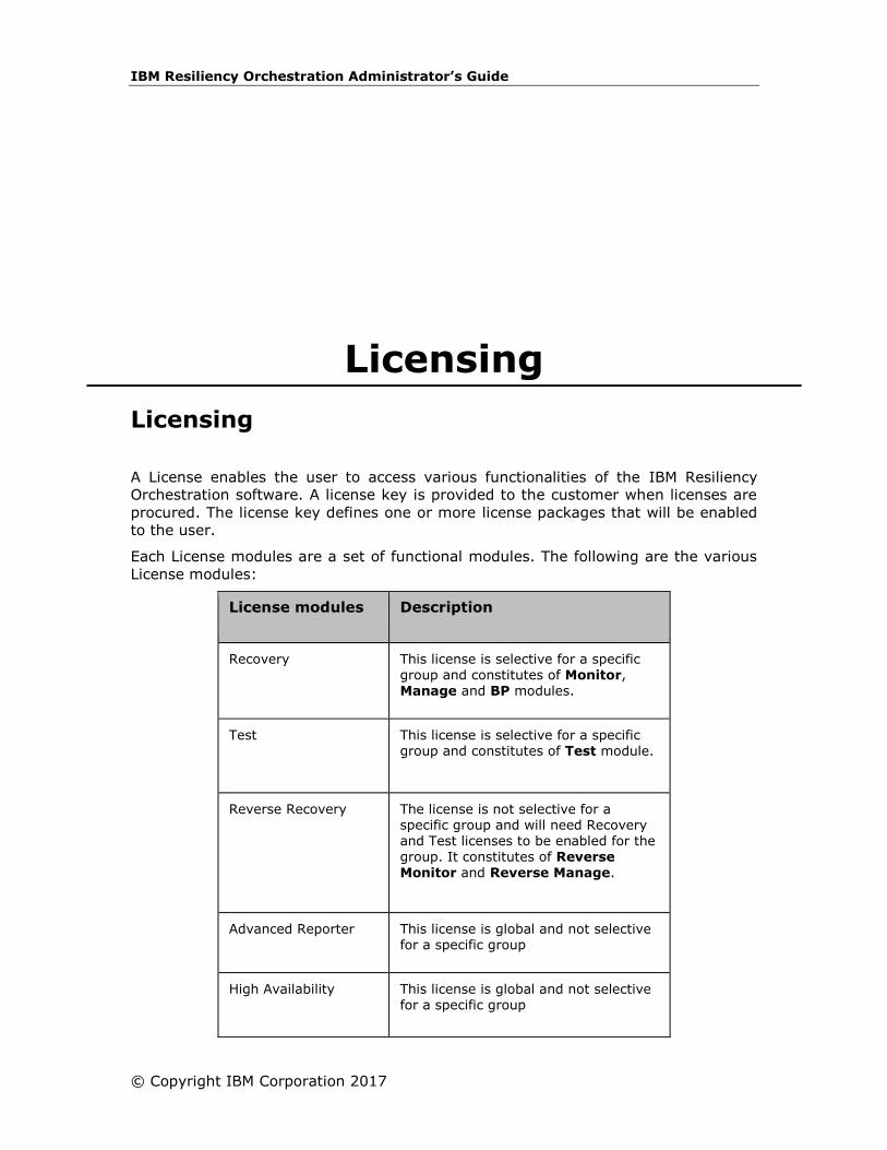
IBM Resiliency Orchestration Administrator’s Guide
© Copyright IBM Corporation 2017
Licensing
Licensing
A License enables the user to access various functionalities of the IBM Resiliency
Orchestration software. A license key is provided to the customer when licenses are
procured. The license key defines one or more license packages that will be enabled
to the user.
Each License modules are a set of functional modules. The following are the various
License modules:
License modules Description
Recovery This license is selective for a specific group and constitutes of Monitor, Manage and BP modules.
Test This license is selective for a specific group and constitutes of Test module.
Reverse Recovery The license is not selective for a specific group and will need Recovery and Test licenses to be enabled for the
group. It constitutes of Reverse Monitor and Reverse Manage.
Advanced Reporter This license is global and not selective for a specific group
High Availability This license is global and not selective for a specific group
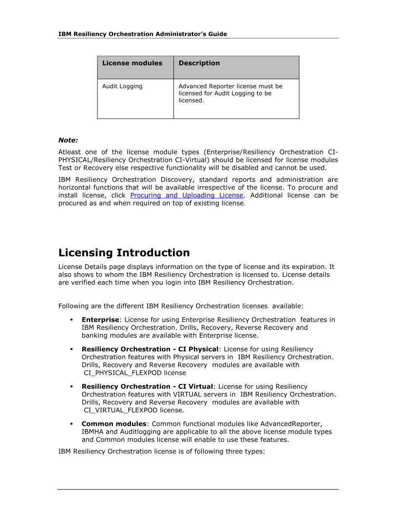
IBM Resiliency Orchestration Administrator’s Guide
License modules Description
Audit Logging Advanced Reporter license must be licensed for Audit Logging to be licensed.
Note:
Atleast one of the license module types (Enterprise/Resiliency Orchestration CI-
PHYSICAL/Resiliency Orchestration CI-Virtual) should be licensed for license modules
Test or Recovery else respective functionality will be disabled and cannot be used.
IBM Resiliency Orchestration Discovery, standard reports and administration are
horizontal functions that will be available irrespective of the license. To procure and
install license, click Procuring and Uploading License. Additional license can be
procured as and when required on top of existing license.
Licensing Introduction
License Details page displays information on the type of license and its expiration. It
also shows to whom the IBM Resiliency Orchestration is licensed to. License details
are verified each time when you login into IBM Resiliency Orchestration.
Following are the different IBM Resiliency Orchestration licenses available:
▪ Enterprise: License for using Enterprise Resiliency Orchestration features in
IBM Resiliency Orchestration. Drills, Recovery, Reverse Recovery and
banking modules are available with Enterprise license.
▪ Resiliency Orchestration - CI Physical: License for using Resiliency
Orchestration features with Physical servers in IBM Resiliency Orchestration.
Drills, Recovery and Reverse Recovery modules are available with
CI_PHYSICAL_FLEXPOD license
▪ Resiliency Orchestration - CI Virtual: License for using Resiliency
Orchestration features with VIRTUAL servers in IBM Resiliency Orchestration.
Drills, Recovery and Reverse Recovery modules are available with
CI_VIRTUAL_FLEXPOD license.
▪ Common modules: Common functional modules like AdvancedReporter,
IBMHA and Auditlogging are applicable to all the above license module types
and Common modules license will enable to use these features.
IBM Resiliency Orchestration license is of following three types:
Licensing
© Copyright IBM Corporation 2017
▪ Evaluation License: This is a demo or trial license that allows you to use
IBM Resiliency Orchestration features for a specified trial period. On
completion of this period, the license expires and you cannot access the
features. Use this license to evaluate the product and to help decide the
license type you would like to go for.
▪ Perpetual License: This license has a module based expire dates. Each
licensed module will have either same or different expiry date. As a result, the
license details page displays individual modules and their expiry dates.
▪ Not for Sale License: This type of license gives unlimited access to all the
features of IBM Resiliency Orchestration. This license does not expire. It is
suitable for IBM™ partners.
In following situations, you need to contact IBM Support at
[email protected] to get assistance on licensing.
▪ When license is not found or found invalid.
▪ When the evaluation (demo) license expires.
▪ When one or more modules of your licensed copy are about to expire.
▪ When one or more module of your licensed copy is expired already.
Procuring and Uploading License
License has to be bought, depending upon the required number of
servers/databases/replications and functional modules and type of license.
Types of Licenses based on expiration:
▪ Expirable License: This license will expire after the specified date.
▪ Perpetual License: This license will never expire.
Contact your supplier for procuring the above licenses.
Viewing License information procured
Validity of procured license and its detailed information can be viewed using the
Command Line Interface (CLI). The CLI should be provided with the licensekey.
Click IBM Resiliency Orchestration Server User Role Management to see the
privileges.
Follow the commands to execute in the CLI:
1. Login into IBM Resiliency Orchestration Server (Linux Server) and open a
command terminal.
2. Run $EAMSROOT/cli/>sh DRMLicense.sh
IBM Resiliency Orchestration Administrator’s Guide
OR
$EAMSROOT/cli>./DRMLicense.sh
Upon running the script, DRMLicense prompt will be displayed:
DRMLicense>
3. Type the following syntax to view licensekey:
view licensekey <-l --licensefile> <licensefile name with path>
For example,
DRMLicense>view licensekey -l /tmp/license.xml
OR
DRMLicense>view licensekey --licensefile /tmp/license.xml
4. Press Enter.
5. If licensekey is valid, the following license information appears on the screen:
▪ Customer Name.
▪ Customer Id and Order Id information.
▪ License module type
▪ License Type.
▪ License expiration information based on the License type.
▪ Product Name and Version.
▪ Information of number of Server/Databases/Replications for Recovery
and Test modules.
▪ License information for other modules.
6. If licensekey is invalid, corresponding error message will be displayed.
Uploading License
A valid license can be uploaded anytime and does not require, restarting of
Resiliency Orchestration Server or its agents. However, Resiliency Orchestration
Server should be running to upload the license.
To upload the license information to the server:
1. Login into IBM Resiliency Orchestration Server (Linux Server) and open a
command terminal.
2. Run $EAMSROOT/cli/>sh DRMLicense.sh
OR
$EAMSROOT/cli>./DRMLicense.sh

Licensing
© Copyright IBM Corporation 2017
3. Upon running the script, DRMLicense prompt will be displayed: DRMLicense>
Type the following syntax to Upload licensekey:
upload licensekey <-l --licensefile> <licensefile name with path>
For example,
DRMLicense>upload licensekey -l /tmp/license.xml
OR
DRMLicense>upload licensekey --licensefile /tmp/license.xml
Press Enter.
4. uploaded license is valid, the message "The license is installed successfully" will
be displayed.
5. uploaded license is invalid, corresponding error message will be displayed.
Upgrading license
Please contact your supplier to procure additional licenses. Refer Uploading license
section above to upload the license.
Note:
Already installed license cannot be uninstalled. For example, if only Recovery license
is currrently installed, it cannot be uninstalled/downgraded by installing Test only
license.
IBM Resiliency Orchestration Administrator’s Guide
View the Uploaded License
Click IBM Resiliency Orchestration Server User Role Management to see the
privileges.
The uploaded license information can be viewed using CLI or User Interface (UI).
Using CLI:
1. Login into IBM Resiliency Orchestration Server (Linux Server) and open a
command terminal
2. Run $EAMSROOT/cli/>sh DRMLicense.sh
OR
$EAMSROOT/cli>./DRMLicense.sh
Upon running the script, DRMLicense prompt will be
displayed:DRMLicense>
Type the following command in the CLI prompt and press enter.
show installed license
The following information appears:
▪ Customer Name
▪ Customer Id
▪ Order Id
▪ License Module Type: Displays list of license module types installed like
Enterprise, CI_VIRTUAL_FLEXPOD, CI_PHYSICAL_FLEXPOD, COMMON etc with
their property details.
▪ License Type- EVAL or REGULAR
▪ License Expiry date for EVAL license type modules.
▪ Module Names: Displays details of Test or Recovery or both modules.
▪ Number of Servers
▪ Number of Database
▪ Number of Replications
▪ Banking functional module is only part of Enterprise license module type.

Licensing
© Copyright IBM Corporation 2017
▪ COMMON Modules: Displays whether the below common modules for all
license module types are licensed or not.
▪ Advanced Reporter
▪ Audit Logging
▪ IBM HA
Using UI:
In the UI, click Admin on the navigation bar. The IBM Resiliency Orchestration
Administration page appears. Scroll down to the License Summary and click Go
to License. The IBM Resiliency Orchestration License Usage Summary page
appears. Refer License Usage.
Enabling / Disabling for a Group
The group has to be in MAINTENANCE/UNMANAGED mode to perform enable/disable
License functionality.
Click IBM Resiliency Orchestration Server User Role Management to see the
privileges.
1. Click DISCOVER > Groups on the navigation bar. The Groups page appears.
2. Click Recovery Group or Application Group tab, the respective Group
Listing page appears.
3. Click the required group from the GROUP NAME column. The Group Details
Page appears.
4. Click Group configuration > License.
5. Select/deselect the License modules check boxes as required.
6. Click Save button.
Note:
Atleast one License Package should be selected, to save.
License Usage
To view the installed license and usage details, click Admin on the navigation bar.
The IBM Resiliency Orchestration Administration page appears. Scroll down to the
License Summary and click Go to License. The IBM Resiliency Orchestration License
Usage Summary page appears.
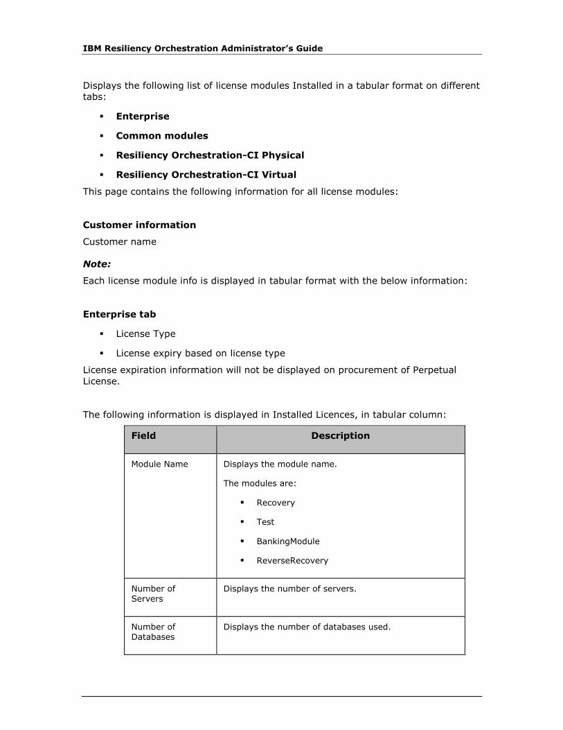
IBM Resiliency Orchestration Administrator’s Guide
Displays the following list of license modules Installed in a tabular format on different
tabs:
▪ Enterprise
▪ Common modules
▪ Resiliency Orchestration-CI Physical
▪ Resiliency Orchestration-CI Virtual
This page contains the following information for all license modules:
Customer information
Customer name
Note:
Each license module info is displayed in tabular format with the below information:
Enterprise tab
▪ License Type
▪ License expiry based on license type
License expiration information will not be displayed on procurement of Perpetual
License.
The following information is displayed in Installed Licences, in tabular column:
Field Description
Module Name Displays the module name.
The modules are:
▪ Recovery
▪ Test
▪ BankingModule
▪ ReverseRecovery
Number of Servers
Displays the number of servers.
Number of Databases
Displays the number of databases used.

Licensing
© Copyright IBM Corporation 2017
Number of Replications
Displays the number of replications done.
Used Licences: The counts represent the aggregate usage of Recovery and Test
license packages. The number of Servers section will include both Physical and
Virtual machines.
The following information is displayed in Used Licences, in a tabular column:
Field Description
Module Name Displays the module name.
The modules are:
▪ Recovery
▪ Test
Number of Servers
Displays the number of servers.
▪ Physical
▪ Virtual
Number of Databases
Displays the number of databases used.
Number of Replications
Displays the number of replications done.
Group wise License Usage Details - These counts represent group-wise usage of
Recovery and Test license packages. Since some of the subsystems would have been
shared among groups, the sum of this group-wise count need not match the above
used license count. The number of Servers section will include both Physical and
Virtual machines.
COMMON modules Tab:
▪ License Type
▪ License expiry based on license type

IBM Resiliency Orchestration Administrator’s Guide
License expiration information will not be displayed on procurement of Perpetual
License.
Displays a list of Installed common license modules with their respective license
status:
▪ AdvancedReporter
▪ AuditLogging
▪ IBM HA
Resiliency Orchestration - CI Virtual tab
▪ License Type
▪ License expiry based on license type
License expiration information will not be displayed on procurement of Perpetual
License.
Displays a list of Installed license modules with their respective license status:
Field Description
Module Name Displays the module name.
The modules are:
▪ Recovery
▪ Test
Number of Virtual Machines
Displays the number of virtual machines used.
The following information is displayed in Used Licences, in a tabular column:
Field Description
Module Name Displays the module name.
The modules are:
▪ Recovery
▪ Test

Licensing
© Copyright IBM Corporation 2017
Field Description
Number of Virtual Machines
Displays the number of virtual machines used.
Group wise License Usage Details - These counts represent group-wise usage of
Recovery and Test license packages. Since some of the subsystems would have been
shared among groups, the sum of this group-wise count need not match the above
used license count. The number of Servers section will include both Physical and
Virtual machines.
Resiliency Orchestration - CI Physical tab
▪ License Type
▪ License expiry based on license type
License expiration information will not be displayed on procurement of Perpetual
License.
Displays a list of Installed license modules with their respective license status:
Field Description
Module Name Displays the module name.
The modules are:
▪ Recovery
▪ Test
Number of Servers
Displays the number of servers being used.
The following information is displayed in Used Licences, in a tabular column:
Field Description
Module Name Displays the module name.
The modules are:
▪ Recovery
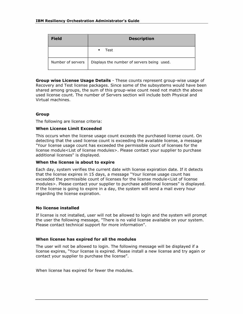
IBM Resiliency Orchestration Administrator’s Guide
Field Description
▪ Test
Number of servers Displays the number of servers being used.
Group wise License Usage Details - These counts represent group-wise usage of
Recovery and Test license packages. Since some of the subsystems would have been
shared among groups, the sum of this group-wise count need not match the above
used license count. The number of Servers section will include both Physical and
Virtual machines.
Group
The following are license criteria:
When License Limit Exceeded
This occurs when the license usage count exceeds the purchased license count. On
detecting that the used license count is exceeding the available license, a message
"Your license usage count has exceeded the permissible count of licenses for the
license module<List of license modules>. Please contact your supplier to purchase
additional licenses" is displayed.
When the license is about to expire
Each day, system verifies the current date with license expiration date. If it detects
that the license expires in 15 days, a message “Your license usage count has
exceeded the permissible count of licenses for the license module<List of license
modules>. Please contact your supplier to purchase additional licenses” is displayed.
If the license is going to expire in a day, the system will send a mail every hour
regarding the license expiration.
No license installed
If license is not installed, user will not be allowed to login and the system will prompt
the user the following message, "There is no valid license available on your system.
Please contact technical support for more information".
When license has expired for all the modules
The user will not be allowed to login. The following message will be displayed if a
license expires, “Your license is expired. Please install a new license and try again or
contact your supplier to purchase the license”.
When license has expired for fewer the modules.

Licensing
© Copyright IBM Corporation 2017
This occurs when the license expired for any license modules. On detecting that the
used license expiry for any license module type, a message "Your license expired of
for the license module<List of license modules>. Please contact your supplier to
purchase additional licenses" is displayed..
Note:
If licenses are expired for all the license module types, user will not be allowed to
login.
When the license is about to expire and exceeded.
This occurs when the license is of expirable type and is about to expire in 15
days;and even if license usage count is exceeded. If the license is going to exipire in
24hours (a day), the system will send mail to all the authorised person at every one
hour. The following message will be displayed "Your license usage count has
exceeded the permissible count of licenses and your license usage count has
exceeded the permissible count of licenses. Please contact your supplier to purchase
additional license".
Home Page Options
The following are the Home page options available for the below licenses:
Home page
options
Recovery
License
Test
License
Recovery
and Test
License
Events List View
Main Dashboard
Continuity List
View
Manage Group List View

IBM Resiliency Orchestration Administrator’s Guide
Home page
options
Recovery
License
Test
License
Recovery
and Test
License
Group Dashboard

IBM Resiliency Orchestration Administrator’s Guide
© Copyright IBM Corp. 2017
High Availability of IBM Resiliency Orchestration Server
High Availability (HA) of IBM Resiliency
Orchestration Server
IBM Resiliency Orchestration comes with the following mechanisms to protect itself
from any disasters:
▪ IBM Resiliency Orchestration Crash Recovery
▪ IBM Resiliency Orchestration Metadata Recovery
▪ IBM Resiliency Orchestration Server Recovery
If IBM Resiliency Orchestration server processes or hardware crashes during
execution, it can recover automatically from the operations that were being executed
at the time of crash.
IBM Resiliency Orchestration server obtains a backup of the meta-data at regular
intervals and stores the meta-data. When IBM Resiliency Orchestration server
crashes, the meta-data is lost from the time it has been backed up last to the time of
server crash. In this case, we need to recover from the last backed up information.
When IBM Resiliency Orchestration server crash occurs during execution of any
continuity operation, Test Exercise operation or an Event Management operation, the
server recovers from these operations and provides an option to resume the
operation after the server is restarted.
During an Application Group crash recovery, first an attempt is made to recover all
its Functional Groups and then the Application Group is recovered. During this
process one or more Recovery Groups might fail leading to an inconsistent state of
Application Group and its Recovery Groups. All further operations performed on the
Application Group might not succeed.
IBM Resiliency Orchestration Administrator’s Guide
When the HA feature is licensed, GUI will enable the following:
▪ Admin > Go to Server Failover Summary > Configuration
▪ Admin > Go to Server Failover Summary > Status
HA System events is displayed in System Events page.
Continuity Operation Recovery
If a Group is in the middle of a continuity operation, IBM Resiliency Orchestration
moves the continuity state of the Group to SHUTDOWN upon startup of IBM
Resiliency Orchestration server.
For example, if the current operation is Failover TRANSIT and the server crashes, the
continuity operation on the Group would be moved to Failover SHUTDOWN state.
Continuity Recovery
If the server has been stopped or crashed in the middle of the workflow execution
you can resume the actions.
Click IBM Resiliency Orchestration Server User Role Management to see the
privileges.
To recover actions in a workflow, select any one of the following workflow
resumption:
1. Click Manage > Recovery group on the navigation bar.
2. The Recovery group listing page appears. This page lists all groups assigned
to the current user.
3. Click desired Group from the GROUP NAME column. The Recovery Groups
page appears.
4. Click Recovery Group to do one of the following:
▪ Initiate NormalCopy
This operation is specific to each Recovery Group and involves periodic
extraction of data from Primary and application of changed data on DR. The
Replication mechanism copies incremental log files from the primary to DR.

High Availability of IBM Resiliency Orchestration Server
© Copyright IBM Corp. 2017
Field Description
Current BCM Displays the current Business Continuity state.
Continue to Initiate the DR Operation? Select this check box if you want to initiate the DR operation.
▪ Initiate Failover
This operation allows Primary server to be brought down and the DR server to
be made available for all business applications.
Field Description
Current BCM Displays the current Business Continuity state.
Continue to initiate the DR Operation Select this check box if you want to initiate the DR operation.
Or Use Change Continuity State( ) icon from Discover > Groups List View.
A dialog box is displayed based on the selection.
This operation lets you move the Business Continuity State of a Group from the
current to a new Business Continuity State. This operation is possible only when the
Group is not executing any continuity operations currently.
Field Description
Current BCM Displays the current Business Continuity state.
Select Target State Select the target state that you want to move from the current state.
The available options are: Normal RESET, Normal INACTIVE, Failover ACTIVE and Fallback ACTIVE.
Continue to Initiate the DR Operation Select this check box if you want to initiate the DR operation.
IBM Resiliency Orchestration Administrator’s Guide
5. Enter the appropriate details in the dialog box.
6. Click Continue to proceed with the resumption OR click Abort to abort
executing the workflow.
Note:
If an action in Action Group was executing at time of crash then the Action Group
execution is started from the first action in the Action Group.
To recover an workflow that has recurring actions (even in Action group), executing
at the time of system crash, then workflow from the first action is restarted
automatically.
Event Management Recovery
The Event recovery page during Group recovery gives an opportunity for the user to
recover at individual event and corresponding policy level. All the events that are in
the middle of execution, at the time of IBM Resiliency Orchestration Server going
down or at the time of Metadata backup is being taken, would be listed during the
recovery. The user can browse through this list and selectively close or resume these
events or corresponding policies from where they have stopped. The user can also
close all the open events in one go by a click of a button, which is applicable if the
recovery is from older metadata backup.
Drills Recovery
If a Group is in the middle of a Drills, IBM Resiliency Orchestration moves the drill
state to SHUTDOWN, upon startup. Along with this, the Drills page provides a
resume operation button called Resume to resume the stopped drill.
IBM Resiliency Orchestration Meta Data
Recovery
IBM Resiliency Orchestration server can be recovered using a backup copy on the
production server itself or using the replicated copy on the DR server. In both cases,
the recovery procedures are similar and performed using the Recovery Wizard.
To use this option, the Backup Manager must be configured to take regular backups
at the desired intervals so that a recent copy of the metadata is available for
recovery.
High Availability of IBM Resiliency Orchestration Server
© Copyright IBM Corp. 2017
To enforce recovery, the IBM Resiliency Orchestration Server needs to be started in
recovery mode after completing the metadata restores procedure or recovery
procedure. To bring up IBM Resiliency Orchestration Server in recovery mode,
execute following command:
$(command prompt) IBM recover
Once IBM Resiliency Orchestration Server comes up in recovery mode; all the
configured availability Groups will be marked for recovery forcing you to complete
the recovery process before doing any normal activity with that Group. An AG can be
marked for recovery only if it has at least one RG associated with it. However an AG
will be in Maintenance mode if it has no RGs associated with it. There is no Recovery
for BG.
Each Group needs to be recovered independently. The recovery starts by clicking on
that particular Group. The recovery process involves 3 different steps as shown
below:
1. Group Status Recovery
During this part of the recovery, you can recover Group status.
The Group Status Recovery page displays the Group status as per the metadata copy
and lets the user to set the correct Group status that represents the current
environment. The Group status selected for an AG will be applicable for all its
associated RGs. In other words, the AG and its RGs possess the same group status
after this “Group status recovery step”.
2. Continuity Mode Recovery
Once the Group status is selected, the continuity mode recovery lets you recover to
the right mode based on the chosen Group status.
During this process, Group’s continuity mode is recovered to the mode that
represents the environment. Similar to the Group status, for an AG the chosen BCM
state is used for its RGs also.
3. Event Policy Recovery
During the Event policy recovery, you can view the policies that are being executed
at the time of the crash. This lets you close all the executing policies or keep them
open for later selective closure or resumption of these policies.

IBM Resiliency Orchestration Administrator’s Guide
If there are no policies executing for corresponding Group then there will be nothing
shown in ‘Event Manager Recovery’ box in the above page will be empty. If an AG is
being recovered, then all policies that are in executing state for all the associated
FGs will be displayed in the above page. To know in detail about the event, click on
the respective event name link on the above page. This opens a page describing the
event. Click on the policy link on the above page to view the corresponding Workflow
status details page.
Once the recovery process is complete a page displaying ‘successful completion of
the operation is shown. Click Done to close the page.
IBM Resiliency Orchestration Server Recovery
IBM Resiliency Orchestration Server Failover
When IBM Resiliency Orchestration Master Server goes down, the control is
transferred to the IBM Resiliency Orchestration slave server. When you bring up the
slave server during the Master Server failover make sure you follow the points given
below:
Click IBM Resiliency Orchestration Server User Role Management to see the
privileges.
Note:
The following is applicable only for Remote Agents.
1. Run following update statement on ‘panaces’ database.
update agent_csa set ac_anode_ip=’<Slave Server IP>’ where
ac_anode_ip=’<Master Server IP>’;
update agent_csa set ac_ipaddress=’<Slave Server IP>’ where
ac_ipaddress=’<Master Server IP>’ and ac_as_id = ‘6’;
Update Vault Agent
update agent_csa set ac_ipaddress=’<Slave Server IP>’ where
ac_ipaddress=’<MasterServer IP>’ and ac_as_id in (select as_id from agent_ssa
where as_name='Vault Agent’);
update component set c_ipaddr=’<Slave Server IP>’ where c_name = ‘<Master
server component name>’;
update component_OSServer set cos_mgmt_ipaddr=’<Slave Server IP>’ where
cos_mgmt_ipaddr = ‘<Master Server IP>’;
Note:

High Availability of IBM Resiliency Orchestration Server
© Copyright IBM Corp. 2017
Replace above statements with the following:
▪ <Slave Server IP> to IP address of the slave server.
▪ <Master Server IP> to IP address of master server which is failed.
▪ <Master server component name> to component name discovered for Master
server.
2. While transferring the control to the slave server, ensure that the IBM
Resiliency Orchestration services on the slave server are started without
stopping the MySQL replication.
3. Manually start IBM Resiliency Orchestration services on the slave server. Once
the services are started, the agents automatically establish connection with the
slave server.
After recovering the IBM Resiliency Orchestration master server, perform the
following steps before starting the IBM Resiliency Orchestration services on the IBM
Resiliency Orchestration master server:
1. Stop the IBM Resiliency Orchestration services on the slave server.
2. Take the MySQL metadata dump on the slave server using the following
command:
mysqldump -u root --databases panaces pfr advancedreporter -R --
triggers > panaces_dump.sql
3. Copy the dump to the master server.
4. Drop the IBM Resiliency Orchestration MariaDB database on the
production server by executing the following command at the command
prompt:
▪ mysql>drop database panaces;
▪ mysql>drop database pfr;
▪ mysql>drop database advancedreporter;
5. Load the MySQL dump that is copied from slave server to master
server by issuing the following command:
i. command from the terminal:
ii. mysql -u root < panaces_dump.sql
6. Run following update statement on ‘panaces’ database.
i. update agent_csa set ac_anode_ip=’<Master Server IP>’ where
ac_anode_ip=’<Slave Server IP>’;
ii. update agent_csa set ac_ipaddress=’<Master Server IP>’ where
ac_ipaddress=’<Slave Server IP>’ and ac_as_id = ‘6’;
iii. update component set c_ipaddr=’<Master Server IP>’ where c_name
= ‘<Master server component name>’;
iv. update component_OSServer set cos_mgmt_ipaddr=’<Master Server
IP>’ where cos_mgmt_ipaddr = ‘<Slave Server IP>’;Note
IBM Resiliency Orchestration Administrator’s Guide
v. Replace in above statements with the following:
▪ <Slave Server IP> to IP address of the actual slave
server.
▪ <Master Server IP> to IP address of actual master server.
▪ <Master server component name> to component name
discovered for Master server.
7. Start IBM Resiliency Orchestration services on the master server.
Once the services are started, the agents automatically establish connection with
the Master server.
IBM Resiliency Orchestration Server Failover configured for UCS Director
When IBM Resiliency Orchestration Master Server goes down, the control is
transferred to the new IBM Resiliency Orchestration.
Click IBM Resiliency Orchestration Server User Role Management to see the
privileges.
When you bring up the new server during the Master Server failover (High
Availability), the following needs to be done:
1 Login to UCS Director UI.
▪ In Physical tab>>Compute
2 Select Default Pod>>Go to IBM Continuity tab > Click icon corresponding to
the UCS Director account and provide the new IP address for IBM Resiliency
Orchestration.
3 Click Save to save the modifications.
▪ Go to Administration, Physical Accounts>
4 Select the IBM Resiliency Orchestration account.
5 Click on Test connection.
Note:
During IBM Resiliency Orchestration fallback, the above changes needs to be
undone.
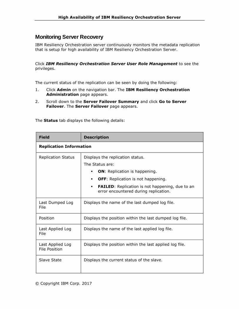
High Availability of IBM Resiliency Orchestration Server
© Copyright IBM Corp. 2017
Monitoring Server Recovery
IBM Resiliency Orchestration server continuously monitors the metadata replication
that is setup for high availability of IBM Resiliency Orchestration Server.
Click IBM Resiliency Orchestration Server User Role Management to see the
privileges.
The current status of the replication can be seen by doing the following:
1. Click Admin on the navigation bar. The IBM Resiliency Orchestration
Administration page appears.
2. Scroll down to the Server Failover Summary and click Go to Server
Failover. The Server Failover page appears.
The Status tab displays the following details:
Field Description
Replication Information
Replication Status Displays the replication status.
The Status are:
▪ ON: Replication is happening.
▪ OFF: Replication is not happening.
▪ FAILED: Replication is not happening, due to an
error encountered during replication.
Last Dumped Log
File
Displays the name of the last dumped log file.
Position Displays the position within the last dumped log file.
Last Applied Log
File
Displays the name of the last applied log file.
Last Applied Log
File Position
Displays the position within the last applied log file.
Slave State Displays the current status of the slave.

IBM Resiliency Orchestration Administrator’s Guide
Field Description
The states are:
▪ Waiting for master update- The initial state before
Connecting to master.
▪ Connecting to master- The thread is attempting to
connect to the master.
▪ Checking master version- A state that occurs very
briefly, after the connection to the master is
established.
▪ Registering slave on master- A state that occurs
very briefly after the connection to the master is
established.
▪ Requesting binlog dump- A state that occurs very
briefly, after the connection to the master is
established. The thread sends to the master a
request for the contents of its binary logs, starting
from the requested binary log file name and
position.
▪ Waiting to reconnect after a failed binlog dump
request- If the binary log dump request failed (due
to disconnection), the thread goes into this state
while it sleeps, then tries to reconnect periodically.
The interval between retries can be specified using
the CHANGE MASTER TO statement or the --
master-connect-retry option.
▪ Reconnecting after a failed binlog dump request-
The thread is trying to reconnect to the master.
▪ Waiting for master to send event- The thread has
connected to the master and it is waiting for binary
log events to arrive. This can last for a long time if
the master is idle. If the wait lasts for
slave_net_timeout seconds, a timeout occurs. At
that point, the thread considers the connection as
broken and makes an attempt to reconnect.
▪ Queueing master event to the relay log- The thread
has read an event and is copying it to the relay log
so that the SQL thread can process it.
▪ Waiting to reconnect after a failed master event
read- An error occurred while reading (due to
disconnection). The thread is sleeping for the
number of seconds set by the CHANGE MASTER TO
statement or --master-connect-retry option
(default 60) before attempting to reconnect.
▪ Reconnecting after a failed master event read- The

High Availability of IBM Resiliency Orchestration Server
© Copyright IBM Corp. 2017
Field Description
thread is trying to reconnect to the master. When
connection is established again, the state becomes
Waiting for master to send event.
▪ Waiting for the slave SQL thread to free enough
relay log space- You are using a nonzero
relay_log_space_limit value, and the relay logs
have grown large enough that their combined size
exceeds this value. The I/O thread is waiting until
the SQL thread frees enough space by processing
relay log contents so that it can delete some relay
log files.
▪ Waiting for slave mutex on exit- A state that occurs
briefly as the thread is stopping.
Last Error Number Displays the last error number.
Last Error Displays the detailed description of the last error.
Configuration Information
Master Replication
Log Buffer Size
Displays the buffer size of the master replication log.
Master Replication
Type
Displays the type of the master replication.
Master Server ID Displays the server ID of the master.
Slave Server ID Displays the server ID of the slave.
Master IP Displays the IP address of the master.
Master User Displays user name of master server.
Master Port Displays the port ID of the master.
Connect Retry Displays the number of seconds after which the master
tries to reconnect. The default value is 60.
3. Click the Configuration tab. The Failover Configuration page appears. This
is used to configure IBM Resiliency Orchestration server for monitoring the
metadata replication.

IBM Resiliency Orchestration Administrator’s Guide
Field Description
Slave Server Host
Name/ IP
Enter hostname or IP address of the configured
MySQL slave server.
MySQL Details on Slave Server
User Name with
Admin Privileges
Enter the user name with administrator
privileges to log on to MariaDB database.
Password Enter the password to log on to MariaDB
database.
Port number Enter the port number on which the MySQL
slave server is listening.
4. Enter appropriate information in the relevant fields. Click Save.
Events
IBM Resiliency Orchestration server also raises an event when the metadata
replication state changes. These events can be seen from the events page and will
categorized under System Events.
The following are the Events related to High Availability of IBM Resiliency
Orchestration:
Event Impact Description Criticality
HASystemEvent001 High
Availability of
IBM
Resiliency
Orchestration
software
resumed
Replication of
IBM
Resiliency
Orchestration
data to
failover site
has started.
INFO
HASystemEvent002 High
Availability of
IBM
Resiliency
Orchestration
software
stopped
Replication of
IBM
Resiliency
Orchestration
data to
failover site
has stopped.
SERIOUS
HASystemEvent003 High
Availability of
IBM
Resiliency
Error
encountered
while
replicating
SERIOUS
High Availability of IBM Resiliency Orchestration Server
© Copyright IBM Corp. 2017
Orchestration
software
encountered
an error
IBMResiliency
Orchestration
data to
failover site.
Metadata Replication using Automated Script
MySQL replication works in a Master-Slave mode where a server acts as master,
while one or more servers act as slaves. IBM Resiliency Orchestration presently
supports one slave process communicating to one master. Any changes made to the
files on the master server are written to the binary log. The binary log files are
updated with the latest changes and the server maintains an index of the files to
keep track of log rotation. A replication process from the slave communicates to the
master to read the binary log and applies the changes to its own database.
Check the pre-requisites and then perform the configurations shown below for
recovery of the IBM Resiliency Orchestration server during failover.
Pre-requisites
▪ Log in as root user.
▪ Create MySQL user for Master and Slave host in mysql.user tables of both
servers with all grant privileges. This is required to validate the MySQL
servers locally and remotely.
Note: Creating MySQL user for Master and Slave host can be avoided if the
user can access mysql as a root user.
(For Example, create two MySQL users for both Master and Slave hosts in Master
host and two MySQL users for both Master and Slave host in Slave host using the
below command.
CREATE USER 'user'@’server ip address’ IDENTIFIED BY 'password';
GRANT ALL ON *.* TO 'user'@'server ip';
GRANT ALL PRIVILEGES ON *.* TO 'user'@'server ip’ WITH GRANT OPTION;
Adding password is optional. If password is not added, leave it blank with the quotes
such as:
CREATE USER 'user'@’server ip address’ IDENTIFIED BY ' ';
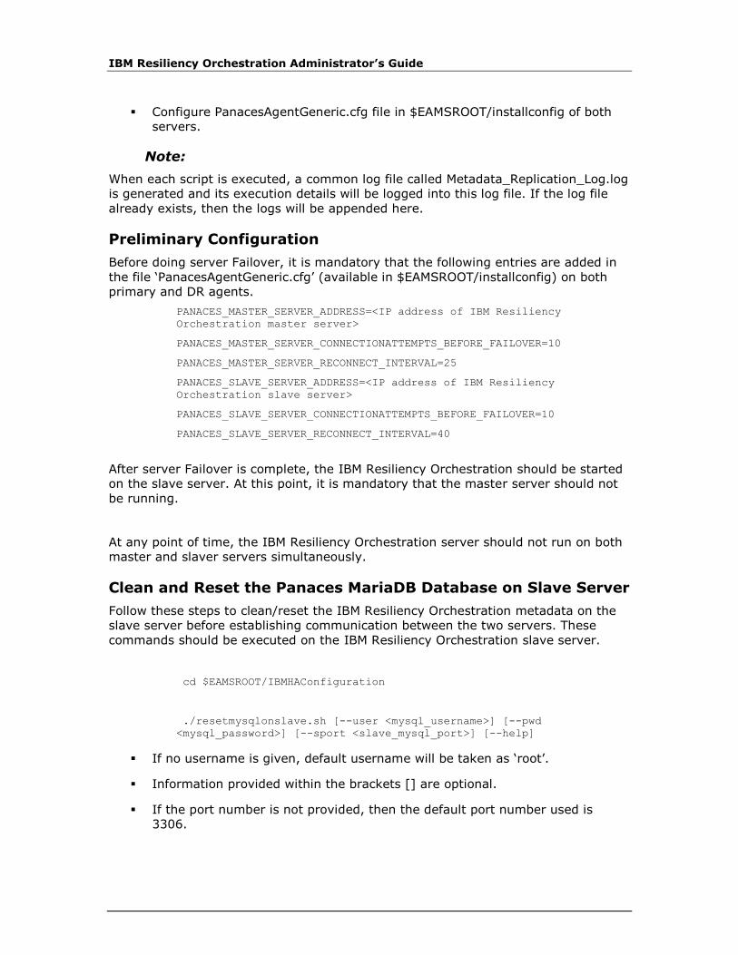
IBM Resiliency Orchestration Administrator’s Guide
▪ Configure PanacesAgentGeneric.cfg file in $EAMSROOT/installconfig of both
servers.
Note:
When each script is executed, a common log file called Metadata_Replication_Log.log
is generated and its execution details will be logged into this log file. If the log file
already exists, then the logs will be appended here.
Preliminary Configuration
Before doing server Failover, it is mandatory that the following entries are added in
the file ‘PanacesAgentGeneric.cfg’ (available in $EAMSROOT/installconfig) on both
primary and DR agents.
PANACES_MASTER_SERVER_ADDRESS=<IP address of IBM Resiliency
Orchestration master server>
PANACES_MASTER_SERVER_CONNECTIONATTEMPTS_BEFORE_FAILOVER=10
PANACES_MASTER_SERVER_RECONNECT_INTERVAL=25
PANACES_SLAVE_SERVER_ADDRESS=<IP address of IBM Resiliency
Orchestration slave server>
PANACES_SLAVE_SERVER_CONNECTIONATTEMPTS_BEFORE_FAILOVER=10
PANACES_SLAVE_SERVER_RECONNECT_INTERVAL=40
After server Failover is complete, the IBM Resiliency Orchestration should be started
on the slave server. At this point, it is mandatory that the master server should not
be running.
At any point of time, the IBM Resiliency Orchestration server should not run on both
master and slaver servers simultaneously.
Clean and Reset the Panaces MariaDB Database on Slave Server
Follow these steps to clean/reset the IBM Resiliency Orchestration metadata on the
slave server before establishing communication between the two servers. These
commands should be executed on the IBM Resiliency Orchestration slave server.
cd $EAMSROOT/IBMHAConfiguration
./resetmysqlonslave.sh [--user <mysql_username>] [--pwd
<mysql_password>] [--sport <slave_mysql_port>] [--help]
▪ If no username is given, default username will be taken as ‘root’.
▪ Information provided within the brackets [] are optional.
▪ If the port number is not provided, then the default port number used is
3306.

High Availability of IBM Resiliency Orchestration Server
© Copyright IBM Corp. 2017
Master Server Configuration
The following are the details of MySQL configuration on the master server.
▪ Stop the IBM Resiliency Orchestration server by entering the following
command
$EAMSROOT/bin/panaces stop
▪ Copy $EAMSROOT/IBMHAConfiguration/mastercnf/my.cnf to /etc
cp $EAMSROOT/IBMHAConfiguration/mastercnf/my.cnf /etc/
▪ Run master.sh
cd $EAMSROOT/IBMHAConfiguration/
./master.sh --master <master_ip> [--muser <master_mysql_username] [--
mpwd <master_mysql_pwd] [--mport <master_mysql_port>] --slave
<slave_ip> [--suser <slave_mysql_user>] [--spwd <slave_mysql_pwd>] [-
-sport <slave_mysql_port>] [--mysqlcnf_loc <location_of_my.cnf>] [--
lic_small/--lic_medium/--lic_large]
▪ Information provided within the brackets [] are optional.
▪ Master IP and slave IP are mandatory. Rest are optional.
▪ If muser/suser is not given, then the default muser/suser is 'root'.
▪ If mport/sport is not given, then the default port is '3306'.
▪ If the location of my.cnf is not specified, then the default location is /etc.
▪ lic_small/lic_medium/lic_large indicate the installation sizes. This is
currently optional.
▪ If MySQL service is not running, start manually
service mysqld start
▪ Copy the panaces.tar file generated in the mentioned directory to the slave
server.
▪ Start the IBM Resiliency Orchestration server by entering the following
command
$EAMSROOT/bin/panaces start
Slave Server Configuration
The following are the details of MySQL configuration on the slave server.
▪ Stop the IBM Resiliency Orchestration server by entering the following
command
$EAMSROOT/bin/panaces stop
▪ Run slave.sh
cd $EAMSROOT/IBMHAConfiguration/
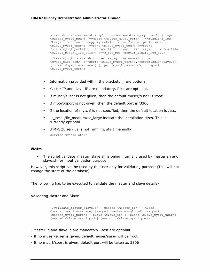
IBM Resiliency Orchestration Administrator’s Guide
slave.sh --master <master_ip> [--muser <master_mysql_user>] [--mpwd
<master_mysql_pwd>] [--mport <master_mysql_port>] [--mysqlcnf_loc
<target_location to copy my.cnf>] --slave <slave_ip> [--suser
<slave_mysql_user>] [--spwd <slave_mysql_pwd>] [--sport
<slave_mysql_port>] [--lic_small|--lic_med|--lic_large] [--m_log_file
<master_binary_log_file>] [--m_log_pos <master_binary_log_pos>]
./resetmysqlonslave.sh [--user <mysql_username>] [--pwd
<mysql_password>] [--sport <slave_mysql_port>]./resetmysqlonslave.sh
[--user <mysql_username>] [--pwd <mysql_password>] [--sport
<slave_mysql_port>]
▪ Information provided within the brackets [] are optional.
▪ Master IP and slave IP are mandatory. Rest are optional.
▪ If muser/suser is not given, then the default muser/suser is 'root'.
▪ If mport/sport is not given, then the default port is '3306'.
▪ If the location of my.cnf is not specified, then the default location is /etc.
▪ lic_small/lic_medium/lic_large indicate the installation sizes. This is
currently optional.
▪ If MySQL service is not running, start manually
service mysqld start
Note:
▪ The script validate_master_slave.sh is being internally used by master.sh and
slave.sh for input validation purpose.
However, this script can be used by the user only for validating purpose (This will not
change the state of the database).
The following has to be executed to validate the master and slave details-
Validating Master and Slave
./validate_master_slave.sh --master <master_ip> [--muser
<master_mysql_username] [--mpwd <master_mysql_pwd] [--mport
<master_mysql_port>] --slave <slave_ip> [--suser <slave_mysql_user>]
[--spwd <slave_mysql_pwd>] [--sport <slave_mysql_port>]
- Master ip and slave ip are mandatory. Rest are optional.
- If no muser/suser is given, default muser/suser will be 'root'
- If no mport/sport is given, default port will be taken as 3306

High Availability of IBM Resiliency Orchestration Server
© Copyright IBM Corp. 2017
▪ Automated scripts will replace my.cnf with default my.cnf. If changes are
required, add them manually.
For details about the design of the script for the preliminary configuration, master
server configuration and slave server configuration, click Script Design.
Metadata Replication with Manual Steps
MySQL replication works in a Master-Slave mode where a server acts as master,
while one or more servers act as slaves. IBM Resiliency Orchestration presently
supports one slave process communicating to one master. Any changes made to the
files on the master server are written to the binary log. The binary log files are
updated with the latest changes and the server maintains an index of the files to
keep track of log rotation. A replication process from the slave communicates to the
master to read the binary log and applies the changes to its own database.
Perform the following configurations to recovery the IBM Resiliency Orchestration
server during failover:
Preliminary Configuration
Before doing server Failover, it is mandatory that the following entries are added in
the file ‘PanacesAgentGenericConf.cfg’ (available in $EAMSROOT/installconfig) on
both primary and DR agents.
PANACES_MASTER_SERVER_ADDRESS=<IP address of IBM Resiliency
Orchestration master server>
PANACES_MASTER_SERVER_CONNECTIONATTEMPTS_BEFORE_FAILOVER=10
PANACES_MASTER_SERVER_RECONNECT_INTERVAL=25
PANACES_SLAVE_SERVER_ADDRESS=<IP address of IBM Resiliency
Orchestration slave server>
PANACES_SLAVE_SERVER_CONNECTIONATTEMPTS_BEFORE_FAILOVER=10
PANACES_SLAVE_SERVER_RECONNECT_INTERVAL=40
After server Failover is complete, the IBM Resiliency Orchestration should be started
on the slave server. At this point, it is mandatory that the master server should not
be running.

IBM Resiliency Orchestration Administrator’s Guide
At any point of time, the IBM Resiliency Orchestration server should not run on both
master and slaver servers simultaneously.
Master server configuration
The following are the details of MySQL configuration on Master server. If there is no
password to access MySQL application, then the part of commands in italics need not
be entered.
▪ Stop the IBM Resiliency Orchestration server by entering the following
command
# /opt/panaces/bin/panaces stop
▪ Add or modify the following entries in /etc/my.cnf at the master site. If the
file does not exist, create one.
[mysqld]
innodb_log_buffer_size=8M
innodb_flush_log_at_trx_commit=1
innodb_file_io_threads=4
max_binlog_size=20M
max_allowed_packet=16M
max_connections=500
log_bin=panacespri_binlog
binlog-do-db=panaces
binlog-do-db=advancedreporter
binlog-do-db=pfr
server-id=1
datadir=/var/lib/mysql
binlog-format=ROW
log_warnings=1
▪ Log in to the master server and issue the following commands:
# MySQL –u root –p
mysql> grant replication slave on *.* to root@<IP address of slave>
-> identified by <’slave mysql password’>;
mysql> grant all on *.* to root@<IP address of slave>
-> identified by < ‘slave mysql password’>;
mysql> flush tables with read lock;
mysql> show master status;
Note down the file name and the position values. If binary log is not already
enabled, the output will be empty. In that case the File name should be
noted as “empty string '' and the position as 4.)

High Availability of IBM Resiliency Orchestration Server
© Copyright IBM Corp. 2017
mysql> exit
▪ Shut down the master server by executing the following command from the
shell prompt
# mysqladmin -u root –p shutdown
▪ Tar the ‘panaces’, ‘advancedreporter’, 'pfr', ‘mysql’ folders, ‘ibdata1’ and
‘ib_logfile*’ data files (for copying into slave server).
# cd /var/lib/mysql
# tar -cvf panaces.tar panaces advancedreporter pfr mysql ibdata1
ib_logfile*
FTP the tar file to the slave server under /var/lib/mysql directory
▪ Restart the server
# service mysql start
▪ Start the IBM Resiliency Orchestration server
# /opt/panaces/bin/panaces start
Slave Server Configuration
The following are the details of MySQL configuration on Slave server. If there is no
password to access MySQL application, then the parts of commands in italics need
not be entered.
▪ If MySQL is already running on the slave server, shut it down.
# mysqladmin -u root –p shutdown
▪ Add or modify the following entries in /etc/my.cnf on slave server. If the file
does not exist, it can be created.
[mysqld]
innodb_log_buffer_size=8M
innodb_file_io_threads=4
max_allowed_packet=16M
max_connections=500
server-id=2
log_warnings=1
▪ Un-tar the data files that was copied from the master server and modify the
permissions.
# cd /var/lib/mysql
#/var/lib/mysql> tar -xvf panaces.tar
#/var/lib/mysql> chown –R mysql:root panaces;
#/var/lib/mysql> chown –R mysql:root advancedreporter;
#/var/lib/mysql> chown –R mysql:root pfr;
#/var/lib/mysql> chown mysql:mysql ibdata1

IBM Resiliency Orchestration Administrator’s Guide
#/var/lib/mysql> chown mysql:mysql ib_logfile*
▪ Restart the MySQL server.
# service mysql start
If master and slave mysql – have different passwords, then login using
master password, and change password to slave password using
command
set password for 'root'@'localhost'=password('slave mysql password');
▪ Log on to the MySQL server and execute the following command to start the
replication.
mysql> change master to master_host=<'IP address of master'>,
-> master_user='root', master_password=<'slave mysql password'>,
-> master_log_file=<'file name noted down in step 1'>,
-> master_log_pos=<position noted down in step 1>;
mysql> start slave;
▪ Check the status by issuing the following command.
mysql> show slave status;
# Grant access to mysql from the master server for monitoring the
replication
mysql> grant all on *.* to root@<IP address of master>
-> identified by < ‘slave mysql password’>;
IBM Resiliency Orchestration server running remote Agents
1. Install PFR on both the Resiliency Orchestration Servers.
2. Create a fileset using PFR GUI to replicate the remote agent configuration and
scripts
i. Fileset Name: DRMHA
ii. Source IP : Master Resiliency Orchestration Server
iii. Target IP : Slave Resiliency Orchestration Server
iv. Replication Interval: Recommended is 30 minutes.
v. Symbolic link option: Replicate symbolic link only
vi. Setup source and targets
a. Source Dir/File : $EAMSROOT /remote (on Master IBM Resiliency
Orchestration)
b. Target Dir/File: $EAMSROOT/remote (on Slave IBM Resiliency
Orchestration)
c. Source Dir/File : $EAMSROOT /work (on Master IBM Resiliency
Orchestration)

High Availability of IBM Resiliency Orchestration Server
© Copyright IBM Corp. 2017
d. Target Dir/File : $EAMSROOT/work (on Slave IBM Resiliency
Orchestration)
Note:
If any other directories are used to keep custom
developed/customer scripts those have to be added to the
replication source and target.
3. Enable Replication: Enable
4. Exclude the libraries and log directories from replication
a.Exclude var directory
i. Source Folder: $EAMSROOT/remote
ii. File/Folder: var
iii. Select Directory
iv. Select case sensitive
v. Select recursive
b. Exclude mssql directory
i. Source Folder: $EAMSROOT/remote
ii. File/Folder: mssql
iii. Select Directory
iv. Select case sensitive
c. Exclude oracle directory
i. Source Folder: $EAMSROOT/remote
ii. File/Folder: oracle
iii. Select Directory
iv. Select case sensitive
5. Sync Delete Files: Uncheck
6. Synchronization: Uncheck
7. Large File Support: Uncheck
8. After Fileset creation, start PFR on Master and Slave Resiliency Orchestration.
9. Replication can be monitored using PFR GUI
Replication User Password Change
1. Master password got changed:
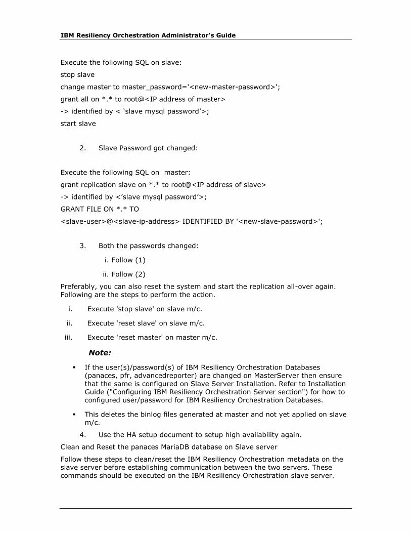
IBM Resiliency Orchestration Administrator’s Guide
Execute the following SQL on slave:
stop slave
change master to master_password='<new-master-password>';
grant all on *.* to root@<IP address of master>
-> identified by < ‘slave mysql password’>;
start slave
2. Slave Password got changed:
Execute the following SQL on master:
grant replication slave on *.* to root@<IP address of slave>
-> identified by <’slave mysql password’>;
GRANT FILE ON *.* TO
<slave-user>@<slave-ip-address> IDENTIFIED BY '<new-slave-password>';
3. Both the passwords changed:
i. Follow (1)
ii. Follow (2)
Preferably, you can also reset the system and start the replication all-over again.
Following are the steps to perform the action.
i. Execute 'stop slave' on slave m/c.
ii. Execute 'reset slave' on slave m/c.
iii. Execute 'reset master' on master m/c.
Note:
▪ If the user(s)/password(s) of IBM Resiliency Orchestration Databases
(panaces, pfr, advancedreporter) are changed on MasterServer then ensure
that the same is configured on Slave Server Installation. Refer to Installation
Guide ("Configuring IBM Resiliency Orchestration Server section") for how to
configured user/password for IBM Resiliency Orchestration Databases.
▪ This deletes the binlog files generated at master and not yet applied on slave
m/c.
4. Use the HA setup document to setup high availability again.
Clean and Reset the panaces MariaDB database on Slave server
Follow these steps to clean/reset the IBM Resiliency Orchestration metadata on the
slave server before establishing communication between the two servers. These
commands should be executed on the IBM Resiliency Orchestration slave server.

High Availability of IBM Resiliency Orchestration Server
© Copyright IBM Corp. 2017
# mysql –u root –p
mysql> stop slave;
mysql> reset slave;
mysql> drop database panaces;
mysql> drop database advancedreporter;
mysql> drop database pfr;
mysql> exit
# mysqladmin -u root –p shutdown
# cd /var/lib/mysql
# /var/lib/mysql> rm ib* *relay*
Note:
Restart the slave server after clearing the IBM Resiliency Orchestration metadata by
executing following command:
# service mysql start
Script Design
MySQL replication works in a Master-Slave mode where a server acts as master,
while one or more servers act as slaves. The script design of the preliminary
configuration, master server configuration and the slave server configuration for
MySQL are listed below.
Prerequisites
▪ The IBMHAConfiguration folder should be copied to $EAMSROOT/ only. The
folder contains the following information:
1. mastercnf/ my.cnf
2. slavecnf/ my.cnf
3. validate_master_slave.sh
4. master.sh
5. slave.sh
6. resetmysqlonslave.sh
▪ Log in as a root user.
▪ Create MySQL users for the master and the slave hosts in mysql.user tables of
both the servers, with all privileges. This is required to validate both the MySQL
servers, locally and remotely.

IBM Resiliency Orchestration Administrator’s Guide
▪ Configure PanacesAgentGeneric.cfg file in $EAMSROOT/installconfig of both the
servers.
Note:
When each script is executed, a common log file called Metadata_Replication_Log.log
is generated and its execution details will be logged into this log file. If the log file
already exists, then the logs will be appended here.
validate_master_slave.sh (Execution of this script is optional. If the user wants to
check the validity of the given input, this script can be used. Although, this script is
being internally called by master.sh and slave.sh)
▪ Reads input in the following order and validates according to the input given:
./validate_master_slave.sh --master <master_ip> [--muser
<master_mysql_username] [--mpwd <master_mysql_pwd] [--mport
<master_mysql_port>] --slave <slave_ip> [--suser <slave_mysql_user>]
[--spwd <slave_mysql_pwd>] [--sport <slave_mysql_port>] [--help]
For example: ./validate_master_slave.sh --master
192.168.1.5 --muser root --mpwd IBM --slave 172.168.1.5 -
-suser root --sport 3308
▪ Master IP and slave IP are mandatory. Rest are optional.
▪ If invalid or no arguments are given, the application will display help
content and exit
▪ Reads all the input given by the user. If the MySQL usernames are not
provided, then the default username will be taken as “root”.
master.sh
▪ Reads input in the following order, then validates and executes according to
the input given:
./master.sh --master <master_ip> [--muser <master_mysql_username] [--
mpwd <master_mysql_pwd] [--mport <master_mysql_port>] --slave
<slave_ip> [--suser <slave_mysql_user>] [--spwd <slave_mysql_pwd>] [-
-sport <slave_mysql_port>] [--mysqlcnf_loc <location_of_my.cnf>] [--
lic_small/--lic_medium/--lic_large] [--help]
For ex: ./master.sh --master 192.168.1.5 --muser root --
mpwd IBM --slave 172.168.1.5 --sport 3308
• If the panaces server is running, then the script will request the user
to stop the panaces server and try again.
• This script calls validate_master_slave.sh with the provided
arguments.
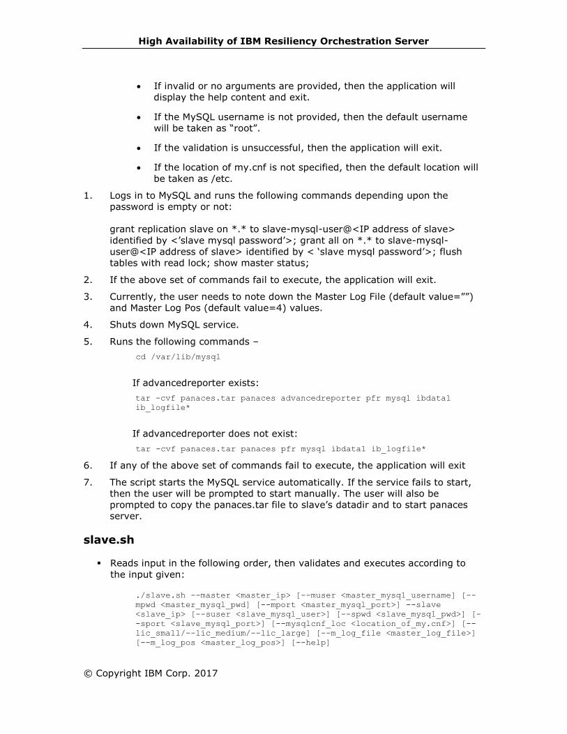
High Availability of IBM Resiliency Orchestration Server
© Copyright IBM Corp. 2017
• If invalid or no arguments are provided, then the application will
display the help content and exit.
• If the MySQL username is not provided, then the default username
will be taken as “root”.
• If the validation is unsuccessful, then the application will exit.
• If the location of my.cnf is not specified, then the default location will
be taken as /etc.
1. Logs in to MySQL and runs the following commands depending upon the
password is empty or not:
grant replication slave on *.* to slave-mysql-user@<IP address of slave>
identified by <’slave mysql password’>; grant all on *.* to slave-mysql-
user@<IP address of slave> identified by < ‘slave mysql password’>; flush
tables with read lock; show master status;
2. If the above set of commands fail to execute, the application will exit.
3. Currently, the user needs to note down the Master Log File (default value=””)
and Master Log Pos (default value=4) values.
4. Shuts down MySQL service.
5. Runs the following commands –
cd /var/lib/mysql
If advancedreporter exists:
tar -cvf panaces.tar panaces advancedreporter pfr mysql ibdata1
ib_logfile*
If advancedreporter does not exist:
tar -cvf panaces.tar panaces pfr mysql ibdata1 ib_logfile*
6. If any of the above set of commands fail to execute, the application will exit
7. The script starts the MySQL service automatically. If the service fails to start,
then the user will be prompted to start manually. The user will also be
prompted to copy the panaces.tar file to slave’s datadir and to start panaces
server.
slave.sh
▪ Reads input in the following order, then validates and executes according to
the input given:
./slave.sh --master <master_ip> [--muser <master_mysql_username] [--
mpwd <master_mysql_pwd] [--mport <master_mysql_port>] --slave
<slave_ip> [--suser <slave_mysql_user>] [--spwd <slave_mysql_pwd>] [-
-sport <slave_mysql_port>] [--mysqlcnf_loc <location_of_my.cnf>] [--
lic_small/--lic_medium/--lic_large] [--m_log_file <master_log_file>]
[--m_log_pos <master_log_pos>] [--help]
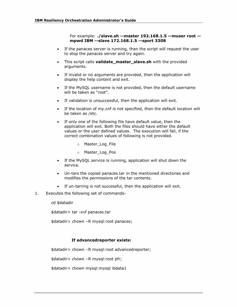
IBM Resiliency Orchestration Administrator’s Guide
For example: ./slave.sh --master 192.168.1.5 --muser root --
mpwd IBM --slave 172.168.1.5 --sport 3308
• If the panaces server is running, then the script will request the user
to stop the panaces server and try again.
• This script calls validate_master_slave.sh with the provided
arguments.
• If invalid or no arguments are provided, then the application will
display the help content and exit.
• If the MySQL username is not provided, then the default username
will be taken as “root”.
• If validation is unsuccessful, then the application will exit.
• If the location of my.cnf is not specified, then the default location will
be taken as /etc.
• If only one of the following file have default value, then the
application will exit. Both the files should have either the default
values or the user defined values. The execution will fail, if the
correct combination values of following is not provided.
o Master_Log_File
o Master_Log_Pos
• If the MySQL service is running, application will shut down the
service.
• Un-tars the copied panaces.tar in the mentioned directories and
modifies the permissions of the tar contents.
• If un-tarring is not successful, then the application will exit.
1. Executes the following set of commands-
cd $datadir
$datadir> tar -xvf panaces.tar
$datadir> chown –R mysql:root panaces;
If advancedreporter exists:
$datadir> chown –R mysql:root advancedreporter;
$datadir> chown –R mysql:root pfr;
$datadir> chown mysql:mysql ibdata1

High Availability of IBM Resiliency Orchestration Server
© Copyright IBM Corp. 2017
$datadir> chown mysql:mysql ib_logfile*
2. If any of the above commands fail to execute, then the application will exit.
3. The script starts MySQL service automatically. If MySQL service doesn’t start
successfully, then the application will exit.
4. If the master and the slave MySQL passwords are different, then the
application logs in using the master’s password and then change the password
to slave's password.
5. Logs in to MySQL server and executes the following commands, depending
upon the mysql passwords are given or not:
change master to master_host=<'IP address of master'>,
master_user='master-mysql-user', master_password=<'slave mysql
password'>, master_log_file=<'file name noted down in step 1'>,
master_log_pos=<position noted down in step 1>; start slave; show slave
status; grant all on *.* to root@<IP address of master> identified by <
‘slave mysql password’>;
6. If any of the above commands fail to execute, then the application will exit.
resetmysqlonslave.sh
▪ Reads input in the following order, then validates and executes according to
the input given:
./resetmysqlonslave.sh [--user <slave_mysql_user>] [--pwd
<slave_mysql_pwd>] [--port <slave_mysql_port>]
For example: ./resetmysqlonslave.sh
• If the MySQL username is not provided, then the default username
will be taken as “root”.
• The application will login to MySQL server and execute the following
set of commands:
stop slave;
reset slave;
drop database panaces;
If advancedreporter exists:
drop database advancedreporter;
drop database pfr;
• After logging out of MySQL server, the script will run the following
commands:
mysqladmin -u <slave-mysqluser> [–p<slave-mysqlpwd>] [-P
<slave_mysql_port>] shutdown
cd /var/lib/mysql
/var/lib/mysql> rm ib* *relay*
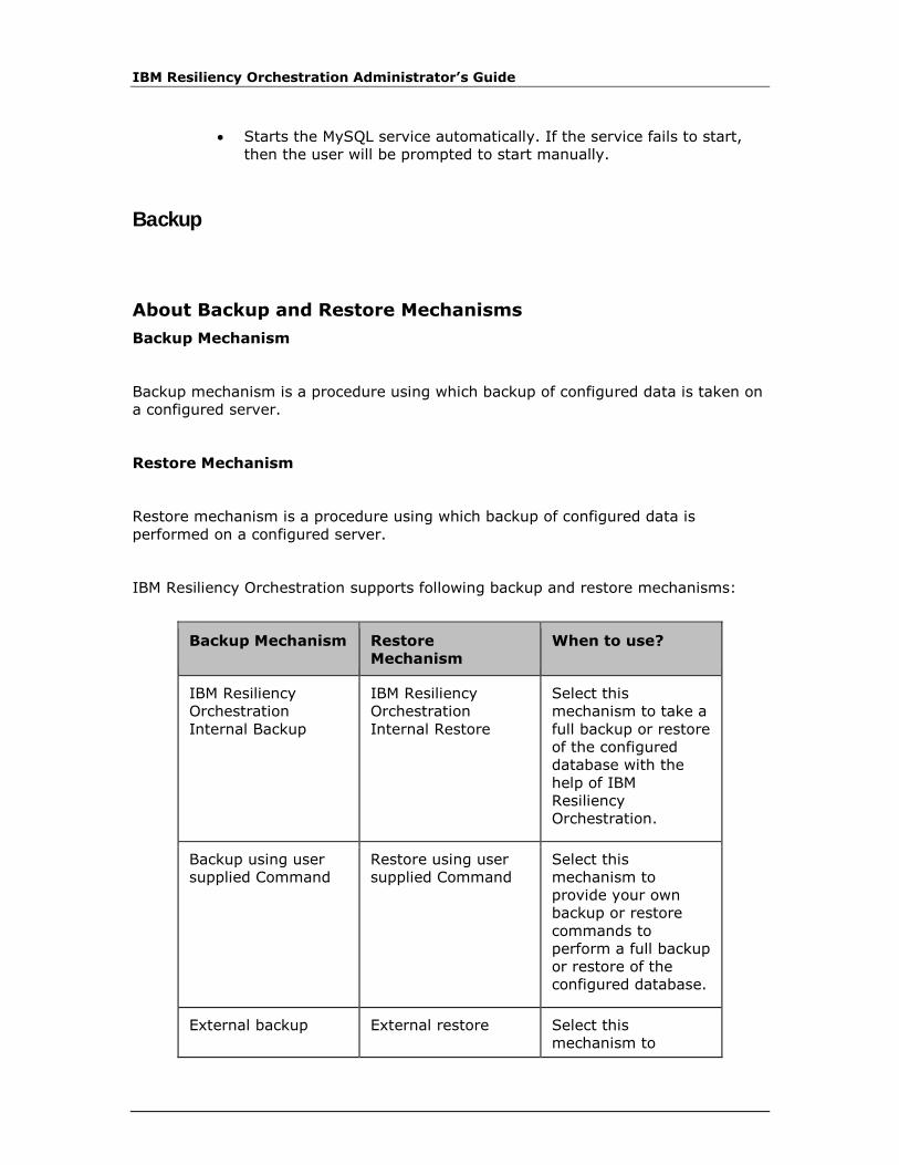
IBM Resiliency Orchestration Administrator’s Guide
• Starts the MySQL service automatically. If the service fails to start,
then the user will be prompted to start manually.
Backup
About Backup and Restore Mechanisms
Backup Mechanism
Backup mechanism is a procedure using which backup of configured data is taken on
a configured server.
Restore Mechanism
Restore mechanism is a procedure using which backup of configured data is
performed on a configured server.
IBM Resiliency Orchestration supports following backup and restore mechanisms:
Backup Mechanism Restore
Mechanism
When to use?
IBM Resiliency
Orchestration
Internal Backup
IBM Resiliency
Orchestration
Internal Restore
Select this
mechanism to take a
full backup or restore
of the configured
database with the
help of IBM
Resiliency
Orchestration.
Backup using user
supplied Command
Restore using user
supplied Command
Select this
mechanism to
provide your own
backup or restore
commands to
perform a full backup
or restore of the
configured database.
External backup External restore Select this
mechanism to
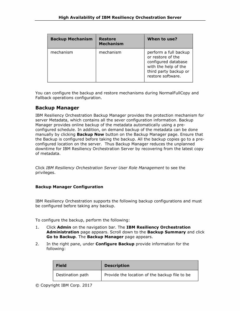
High Availability of IBM Resiliency Orchestration Server
© Copyright IBM Corp. 2017
Backup Mechanism Restore
Mechanism
When to use?
mechanism mechanism perform a full backup
or restore of the
configured database
with the help of the
third party backup or
restore software.
You can configure the backup and restore mechanisms during NormalFullCopy and
Fallback operations configuration.
Backup Manager
IBM Resiliency Orchestration Backup Manager provides the protection mechanism for
server Metadata, which contains all the sever configuration information. Backup
Manager provides online backup of the metadata automatically using a pre-
configured schedule. In addition, on demand backup of the metadata can be done
manually by clicking Backup Now button on the Backup Manager page. Ensure that
the Backup is configured before taking the backup. All the backup copies go to a pre-
configured location on the server. Thus Backup Manager reduces the unplanned
downtime for IBM Resiliency Orchestration Server by recovering from the latest copy
of metadata.
Click IBM Resiliency Orchestration Server User Role Management to see the
privileges.
Backup Manager Configuration
IBM Resiliency Orchestration supports the following backup configurations and must
be configured before taking any backup.
To configure the backup, perform the following:
1. Click Admin on the navigation bar. The IBM Resiliency Orchestration
Administration page appears. Scroll down to the Backup Summary and click
Go to Backup. The Backup Manager page appears.
2. In the right pane, under Configure Backup provide information for the
following:
Field Description
Destination path Provide the location of the backup file to be

IBM Resiliency Orchestration Administrator’s Guide
saved.
Backup at Select the time slot (24 hrs time scale) of
backup from the drop-down list.
Frequency There are two types of frequency backup:
▪ Daily – Backup is fired daily at a
configured time in Backup At field.
For example, if the configured time is
15:00 hrs, then the backup is taken at
15.00 hrs everyday.
▪ Weekly – In this case backup is fired
weekly on the mentioned day at a
specified time. For example, if the day
mentioned is Sunday, and the time of
backup is 15.00 hrs, then on every
Sunday the files are backed up at
15.00 hrs.
Active Copies This displays the number of active copies and
about the availability of number of latest
generated backup copies in that path.
3. Click Save to save the backup details.
Listing Backup Manager Information:
To view the configured backup information, perform the following steps:
1. Click Admin on the navigation bar. The IBM Resiliency Orchestration
Administration page appears. Scroll down to the Backup Summary and click
Go to Backup. The Backup Manager page appears.
2. This page provides the configured backup information (refer to the above table)
along with the following additional details of the backup file:
▪ Backup Destination Path
▪ Frequency of Backup
▪ Frequency of Backup Day
▪ Scheduled Backup time
▪ Number of Active Copies
▪ Size of Backup in Kb
▪ Time of Last Backup
▪ Backup File name
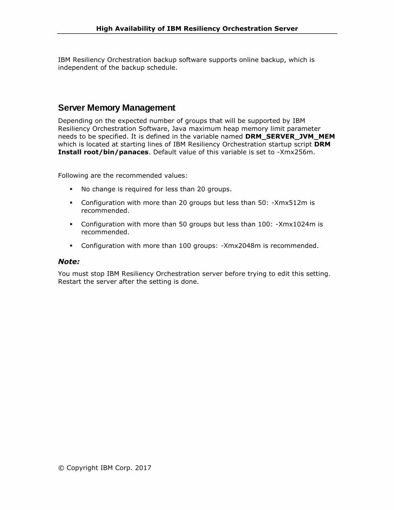
High Availability of IBM Resiliency Orchestration Server
© Copyright IBM Corp. 2017
IBM Resiliency Orchestration backup software supports online backup, which is
independent of the backup schedule.
Server Memory Management
Depending on the expected number of groups that will be supported by IBM
Resiliency Orchestration Software, Java maximum heap memory limit parameter
needs to be specified. It is defined in the variable named DRM_SERVER_JVM_MEM
which is located at starting lines of IBM Resiliency Orchestration startup script DRM
Install root/bin/panaces. Default value of this variable is set to -Xmx256m.
Following are the recommended values:
▪ No change is required for less than 20 groups.
▪ Configuration with more than 20 groups but less than 50: -Xmx512m is
recommended.
▪ Configuration with more than 50 groups but less than 100: -Xmx1024m is
recommended.
▪ Configuration with more than 100 groups: -Xmx2048m is recommended.
Note:
You must stop IBM Resiliency Orchestration server before trying to edit this setting.
Restart the server after the setting is done.
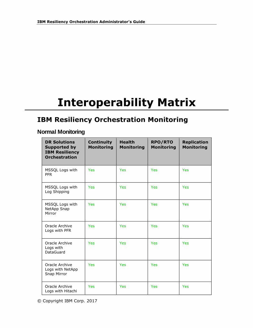
IBM Resiliency Orchestration Administrator’s Guide
© Copyright IBM Corp. 2017
Interoperability Matrix
IBM Resiliency Orchestration Monitoring
Normal Monitoring
DR Solutions
Supported by
IBM Resiliency
Orchestration
Continuity
Monitoring
Health
Monitoring
RPO/RTO
Monitoring
Replication
Monitoring
MSSQL Logs with
PFR
Yes Yes Yes Yes
MSSQL Logs with Log Shipping
Yes Yes Yes Yes
MSSQL Logs with NetApp Snap Mirror
Yes Yes Yes Yes
Oracle Archive Logs with PFR
Yes Yes Yes Yes
Oracle Archive Logs with DataGuard
Yes Yes Yes Yes
Oracle Archive Logs with NetApp Snap Mirror
Yes Yes Yes Yes
Oracle Archive Logs with Hitachi
Yes Yes Yes Yes
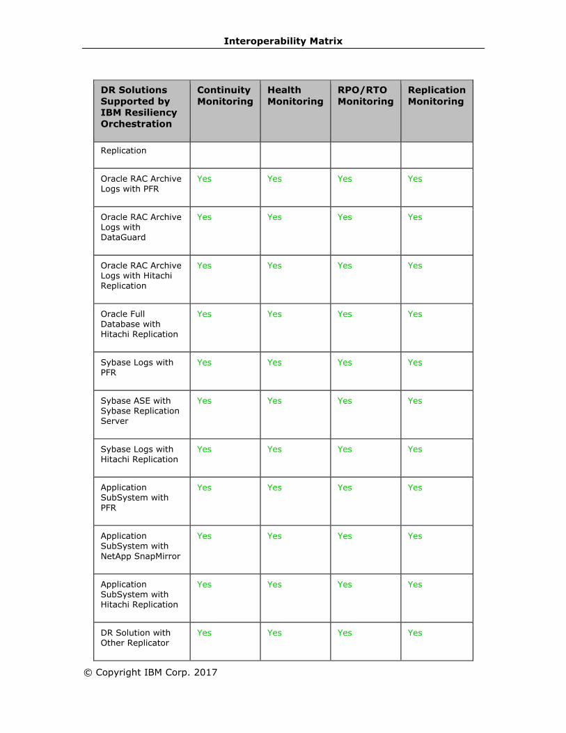
Interoperability Matrix
© Copyright IBM Corp. 2017
DR Solutions
Supported by
IBM Resiliency
Orchestration
Continuity
Monitoring
Health
Monitoring
RPO/RTO
Monitoring
Replication
Monitoring
Replication
Oracle RAC Archive Logs with PFR
Yes Yes Yes Yes
Oracle RAC Archive Logs with
DataGuard
Yes Yes Yes Yes
Oracle RAC Archive Logs with Hitachi Replication
Yes Yes Yes Yes
Oracle Full Database with Hitachi Replication
Yes Yes Yes Yes
Sybase Logs with PFR
Yes Yes Yes Yes
Sybase ASE with Sybase Replication Server
Yes Yes Yes Yes
Sybase Logs with Hitachi Replication
Yes Yes Yes Yes
Application SubSystem with
PFR
Yes Yes Yes Yes
Application
SubSystem with
NetApp SnapMirror
Yes Yes Yes Yes
Application SubSystem with Hitachi Replication
Yes Yes Yes Yes
DR Solution with Other Replicator
Yes Yes Yes Yes

IBM Resiliency Orchestration Administrator’s Guide
DR Solutions
Supported by
IBM Resiliency
Orchestration
Continuity
Monitoring
Health
Monitoring
RPO/RTO
Monitoring
Replication
Monitoring
Sybase Logs with HP XP Replication
Yes Yes Yes Yes
Application SubSystem with HP XP Replication
Yes Yes Yes Yes
Oracle Archive Logs with HP XP Replication
Yes Yes Yes Yes
Oracle RAC Archive Logs with HP XP Replication
Yes Yes Yes Yes
Oracle Full Database with HP XP Replication
Yes Yes Yes Yes
Oracle RAC Full Database with HP XP Replication
Yes Yes Yes Yes
Oracle Full Database with EMC SRDF Replication
Yes Yes Yes Yes
Oracle RAC Full Database with EMC SRDF Replication
Yes Yes Yes Yes
Application
SubSystem with EMC SRDF Replication
Yes Yes Yes Yes
PostgreSQL with SR
Yes Yes Yes Yes
Oracle Full Database with IBM Global Mirror
Yes Yes Yes Yes
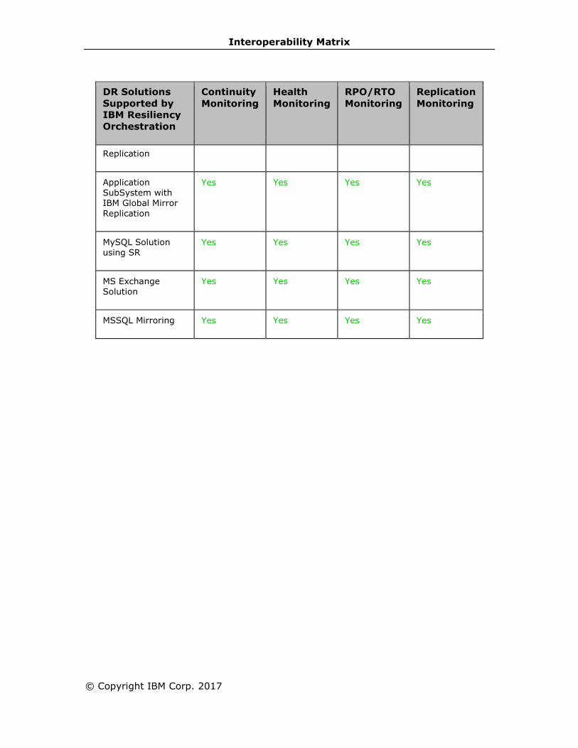
Interoperability Matrix
© Copyright IBM Corp. 2017
DR Solutions
Supported by
IBM Resiliency
Orchestration
Continuity
Monitoring
Health
Monitoring
RPO/RTO
Monitoring
Replication
Monitoring
Replication
Application SubSystem with IBM Global Mirror
Replication
Yes Yes Yes Yes
MySQL Solution using SR
Yes Yes Yes Yes
MS Exchange Solution
Yes Yes Yes Yes
MSSQL Mirroring Yes Yes Yes Yes

IBM Resiliency Orchestration Administrator’s Guide
Reverse Monitoring
DR Solutions
Supported by
IBM Resiliency
Orchestration
Continuity
Monitoring
Health
Monitoring
RPO/RTO
Monitoring
Replication
Monitoring
MSSQL Logs with PFR
Yes Yes Yes Yes
MSSQL Logs with Log Shipping
Yes Yes Yes Yes
MSSQL Logs with NetApp Snap Mirror
Yes Yes Yes Yes
Oracle Archive Logs with PFR
Yes Yes Yes Yes
Oracle Archive Logs with DataGuard
Yes Yes Yes Yes
Oracle Archive Logs with NetApp Snap Mirror
Yes Yes Yes Yes
Oracle Archive Logs with Hitachi Replication
Yes Yes Yes Yes
Oracle RAC Archive Logs with PFR
Yes Yes Yes Yes
Oracle RAC Archive Logs with
DataGuard
Yes Yes Yes Yes
Oracle RAC Archive Logs with Hitachi
Replication
Yes Yes Yes Yes
Oracle Full Database with Hitachi Replication
No Yes No Yes

Interoperability Matrix
© Copyright IBM Corp. 2017
DR Solutions
Supported by
IBM Resiliency
Orchestration
Continuity
Monitoring
Health
Monitoring
RPO/RTO
Monitoring
Replication
Monitoring
Sybase Logs with PFR
No Yes No Yes
Sybase ASE with Sybase Replication Server
No Yes No Yes
Sybase Logs with Hitachi Replication
No Yes No Yes
Application SubSystem with PFR
Yes Yes Yes Yes
Application SubSystem with NetApp SnapMirror
Yes Yes Yes Yes
Application
SubSystem with Hitachi Replication
Yes Yes Yes Yes
DR Solution with Other Replicator
Yes Yes Yes Yes
Sybase Logs with HP XP Replication
No Yes No Yes
Application SubSystem with HP XP Replication
Yes Yes Yes Yes
Oracle Archive Logs with HP XP Replication
Yes Yes Yes Yes
Oracle RAC Archive Logs with HP XP Replication
Yes Yes Yes Yes
Oracle Full Database with HP
No Yes No Yes

IBM Resiliency Orchestration Administrator’s Guide
DR Solutions
Supported by
IBM Resiliency
Orchestration
Continuity
Monitoring
Health
Monitoring
RPO/RTO
Monitoring
Replication
Monitoring
XP Replication
Oracle RAC Full Database with HP XP Replication
No Yes No Yes
Oracle Full
Database with EMC SRDF Replication
No Yes No Yes
Oracle RAC Full Database with EMC SRDF Replication
No Yes No Yes
Application SubSystem with EMC SRDF Replication
Yes Yes Yes Yes
PostgreSQL with
SR Yes Yes Yes Yes
Oracle Full Database with IBM Global Mirror Replication
No Yes No Yes
Application SubSystem with IBM Global Mirror Replication
Yes Yes Yes Yes
MySQL Solution
using SR Yes Yes Yes Yes
MS Exchange Solution
Yes Yes Yes Yes
MSSQL Mirroring Yes Yes Yes Yes

Interoperability Matrix
© Copyright IBM Corp. 2017
Note:
Reverse Monitoring (monitoring while the Group is in Switchover Mode) is a licensed
feature. The Replication, Continuity and RPO Monitor features be allowed by the
product only if Reverse Monitoring is enabled. Contact IBM Service to enable this
feature.
However, Health Monitoring even though is a Reverse Monitoring feature, is not
licensed, as this is required to ensure the successful execution of Switchback
workflow.
IBM Resiliency Orchestration Recovery
Automation
Normal Management
DR Solutions
Supported by
IBM Resiliency
Orchestration
Replication
Start/Stop
NormalCopy Failover
MSSQL Logs with
PFR
Yes Prepackaged workflow Prepackaged
workflow
MSSQL Logs with Log Shipping
Yes Not Required Prepackaged workflow
MSSQL Logs with NetApp Snap Mirror
Yes Not Required Prepackaged workflow
Oracle Archive Logs with PFR
Yes Prepackaged xml workflow
Prepackaged xml workflow
Oracle Archive Logs with DataGuard
Yes Not Required Prepackaged xml workflow
Oracle Archive logs with NetApp Snap Mirror
Yes Not Required Prepackaged workflow
Oracle Archive Logs with Hitachi
Yes Sample workflow Sample workflow
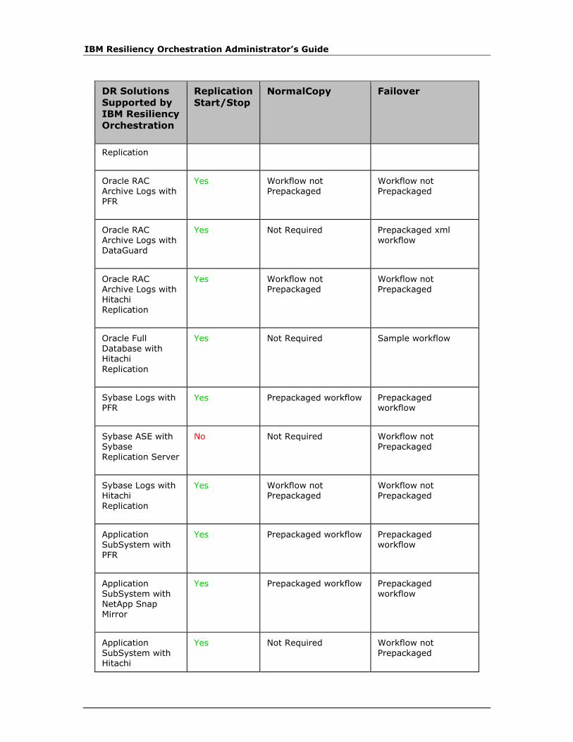
IBM Resiliency Orchestration Administrator’s Guide
DR Solutions
Supported by
IBM Resiliency
Orchestration
Replication
Start/Stop
NormalCopy Failover
Replication
Oracle RAC Archive Logs with PFR
Yes Workflow not Prepackaged
Workflow not Prepackaged
Oracle RAC
Archive Logs with DataGuard
Yes Not Required Prepackaged xml
workflow
Oracle RAC Archive Logs with Hitachi Replication
Yes Workflow not Prepackaged
Workflow not Prepackaged
Oracle Full Database with Hitachi
Replication
Yes Not Required Sample workflow
Sybase Logs with PFR
Yes Prepackaged workflow Prepackaged workflow
Sybase ASE with Sybase Replication Server
No Not Required Workflow not Prepackaged
Sybase Logs with Hitachi Replication
Yes Workflow not Prepackaged
Workflow not Prepackaged
Application SubSystem with
PFR
Yes Prepackaged workflow Prepackaged workflow
Application SubSystem with NetApp Snap Mirror
Yes Prepackaged workflow Prepackaged workflow
Application SubSystem with Hitachi
Yes Not Required Workflow not Prepackaged

Interoperability Matrix
© Copyright IBM Corp. 2017
DR Solutions
Supported by
IBM Resiliency
Orchestration
Replication
Start/Stop
NormalCopy Failover
Replication
DR Solution with Other Replicator
Yes Workflow not Prepackaged
Workflow not Prepackaged
Sybase Logs with HP XP Replication
Yes Workflow not Prepackaged
Workflow not Prepackaged
Application SubSystem with HP XP Replication
Yes Not Required Workflow not Prepackaged
Oracle Archive Logs with HP XP Replication
Yes Sample workflow Sample workflow
Oracle RAC Archive Logs with HP XP Replication
Yes Workflow not Prepackaged
Workflow not Prepackaged
Oracle Full Database with HP XP Replication
Yes Not Required Sample workflow
Oracle RAC Full Database with HP XP Replication
Yes Not Required Sample workflow
Oracle Full Database with EMC SRDF Replication
Yes Not Required Prepackaged workflow
Oracle RAC Full Database with EMC SRDF Replication
Yes Not Required Prepackaged workflow
Application SubSystem with EMC SRDF Replication
Yes Not Required Workflow not prepackaged

IBM Resiliency Orchestration Administrator’s Guide
DR Solutions
Supported by
IBM Resiliency
Orchestration
Replication
Start/Stop
NormalCopy Failover
PostgreSQL with SR
No Not Required Prepackaged workflow
Oracle Full Database with IBM Global Mirror Replication
Yes Not Required Prepackaged workflow
Application SubSystem with IBM Global Mirror Replication
Yes Not Required Workflow not prepackaged
MySQL Solution using SR
Yes Not Required Prepackaged xml workflow
MS Exchange Solution
Yes Not Required Workflow not Prepackaged
MSSQL Mirroring Yes Not Required Workflow not Prepackaged
Terminology
1. Prepackaged workflow: Workflow is preloaded when the group is created.
Workflow is readily available for the user to execute/initiate.
2. Prepackaged xml workflow: Workflow is provided as XML and can be
imported into the group.
3. Sample workflow: Sample workflow is available in XML format and can be
imported into the group after doing necessary changes to the XML as the case
may be.
4. Not Required: No workflow is required.
5. Workflow not Prepackaged: Workflow is not available in the product.
Placeholder for the workflow is readily available. It is upto the user to
create/define the workflow either by using RAL library or XML import.
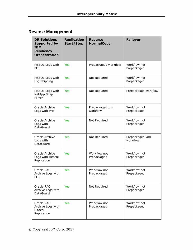
Interoperability Matrix
© Copyright IBM Corp. 2017
Reverse Management
DR Solutions
Supported by
IBM
Resiliency
Orchestration
Replication
Start/Stop
Reverse
NormalCopy
Failover
MSSQL Logs with PFR
Yes Prepackaged workflow Workflow not Prepackaged
MSSQL Logs with
Log Shipping Yes Not Required Workflow not
Prepackaged
MSSQL Logs with NetApp Snap Mirror
Yes Not Required Prepackaged workflow
Oracle Archive Logs with PFR
Yes Prepackaged xml workflow
Workflow not Prepackaged
Oracle Archive Logs with DataGuard
Yes Not Required Workflow not Prepackaged
Oracle Archive Logs with DataGuard
Yes Not Required Prepackaged xml workflow
Oracle Archive Logs with Hitachi Replication
Yes Workflow not Prepackaged
Workflow not Prepackaged
Oracle RAC Archive Logs with PFR
Yes Workflow not Prepackaged
Workflow not Prepackaged
Oracle RAC Archive Logs with DataGuard
Yes Not Required Workflow not Prepackaged
Oracle RAC Archive Logs with Hitachi Replication
Yes Workflow not Prepackaged
Workflow not Prepackaged

IBM Resiliency Orchestration Administrator’s Guide
DR Solutions
Supported by
IBM
Resiliency
Orchestration
Replication
Start/Stop
Reverse
NormalCopy
Failover
Oracle Full Database with Hitachi Replication
Yes Not Required Workflow not Prepackaged
Sybase Logs with
PFR
Yes Workflow not
Prepackaged
Workflow not
Prepackaged
Sybase ASE with Sybase
Replication Server
No Workflow not Prepackaged
Workflow not Prepackaged
Sybase Logs with Hitachi Replication
Yes Workflow not Prepackaged
Workflow not Prepackaged
Application SubSystem with
PFR
Yes Prepackaged workflow Workflow not Prepackaged
Application SubSystem with
Hitachi Replication
Yes Not Required Workflow not Prepackaged
DR Solution with Other Replicator
Yes Workflow not Prepackaged
Workflow not Prepackaged
Sybase Logs with
HP XP Replication
Yes Workflow not
Prepackaged
Workflow not
Prepackaged
Application SubSystem with HP XP Replication
Yes Not Required Workflow not Prepackaged
Oracle Archive Logs with HP XP Replication
Yes Workflow not Prepackaged
Workflow not Prepackaged

Interoperability Matrix
© Copyright IBM Corp. 2017
DR Solutions
Supported by
IBM
Resiliency
Orchestration
Replication
Start/Stop
Reverse
NormalCopy
Failover
Oracle RAC Archive Logs with HP XP Replication
Yes Workflow not Prepackaged
Workflow not Prepackaged
Oracle Full Database with HP
XP Replication
Yes Not Required Workflow not Prepackaged
Oracle RAC Full Database with HP
XP Replication
Yes Not Required Workflow not Prepackaged
Oracle Full Database with
EMC SRDF Replication
Yes Not Required Prepackaged workflow
Oracle RAC Full Database with
EMC SRDF Replication
Yes Not Required Prepackaged workflow
Application SubSystem with EMC SRDF Replication
Yes Not Required Workflow not Prepackaged
PostgreSQL with SR
No Not Required Workflow not Prepackaged
Oracle Full Database with
IBM Global Mirror Replication
Yes Not Required Workflow not Prepackaged
Application SubSystem with IBM Global Mirror Replication
Yes Not Required Workflow not Prepackaged
MySQL Solution Yes Not Required Workflow not

IBM Resiliency Orchestration Administrator’s Guide
DR Solutions
Supported by
IBM
Resiliency
Orchestration
Replication
Start/Stop
Reverse
NormalCopy
Failover
using SR Prepackaged
MS Exchange Solution
Yes Not Required Workflow not Prepackaged
MSSQL Mirroring Yes Not Required Workflow not
Prepackaged
Terminology
1. Prepackaged workflow: Workflow is preloaded when the group is created.
Workflow is readily available for the user to execute/initiate.
2. Prepackaged xml workflow: Workflow is provided as XML and can be
imported into the group.
3. Sample workflow: Sample workflow is available in XML format and can be
imported into the group after doing necessary changes to the XML as the case
may be.
4. Not Required: No workflow is required.
5. Workflow not Prepackaged: Workflow is not available in the product.
Placeholder for the workflow is readily available. It is upto the user to
create/define the workflow either by using RAL library or XML import.
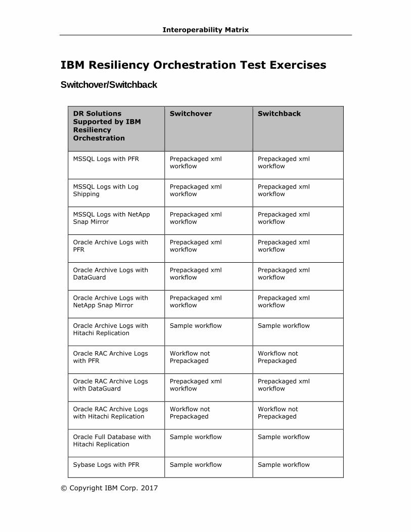
Interoperability Matrix
© Copyright IBM Corp. 2017
IBM Resiliency Orchestration Test Exercises
Switchover/Switchback
DR Solutions
Supported by IBM
Resiliency
Orchestration
Switchover Switchback
MSSQL Logs with PFR Prepackaged xml workflow
Prepackaged xml workflow
MSSQL Logs with Log Shipping
Prepackaged xml workflow
Prepackaged xml workflow
MSSQL Logs with NetApp Snap Mirror
Prepackaged xml workflow
Prepackaged xml workflow
Oracle Archive Logs with PFR
Prepackaged xml workflow
Prepackaged xml workflow
Oracle Archive Logs with DataGuard
Prepackaged xml workflow
Prepackaged xml workflow
Oracle Archive Logs with NetApp Snap Mirror
Prepackaged xml workflow
Prepackaged xml workflow
Oracle Archive Logs with Hitachi Replication
Sample workflow Sample workflow
Oracle RAC Archive Logs with PFR
Workflow not Prepackaged
Workflow not Prepackaged
Oracle RAC Archive Logs with DataGuard
Prepackaged xml workflow
Prepackaged xml workflow
Oracle RAC Archive Logs with Hitachi Replication
Workflow not Prepackaged
Workflow not Prepackaged
Oracle Full Database with Hitachi Replication
Sample workflow Sample workflow
Sybase Logs with PFR Sample workflow Sample workflow

IBM Resiliency Orchestration Administrator’s Guide
DR Solutions
Supported by IBM
Resiliency
Orchestration
Switchover Switchback
Sybase ASE with Sybase Replication Server
Workflow not Prepackaged
Workflow not Prepackaged
Sybase Logs with Hitachi Replication
Workflow not Prepackaged
Workflow not Prepackaged
Application SubSystem with
PFR
Prepackaged workflow Prepackaged workflow
Application SubSystem with NetApp SnapMirror
Prepackaged workflow Prepackaged workflow
Application SubSystem with Hitachi Replication
Workflow not Prepackaged
Workflow not Prepackaged
DR Solution with Other Replicator
Workflow not Prepackaged
Workflow not Prepackaged
Sybase Logs with HP XP
Replication
Workflow not
Prepackaged
Workflow not
Prepackaged
Application SubSystem with HP XP Replication
Workflow not Prepackaged
Workflow not Prepackaged
Oracle Archive Logs with HP XP Replication
Sample workflow Sample workflow
Oracle RAC Archive Logs with HP XP Replication
Workflow not Prepackaged
Workflow not Prepackaged
Oracle Full Database with
HP XP Replication
Sample workflow Sample workflow
Oracle RAC Full Database with HP XP Replication
Sample workflow Sample workflow
Oracle Full Database with EMC SRDF Replication
Prepackaged xml workflow
Prepackaged xml workflow
Oracle RAC Full Database Prepackaged xml Prepackaged xml

Interoperability Matrix
© Copyright IBM Corp. 2017
DR Solutions
Supported by IBM
Resiliency
Orchestration
Switchover Switchback
with EMC SRDF Replication workflow workflow
Application SubSystem with EMC SRDF Replication
Workflow not Prepackaged
Workflow not Prepackaged
PostgreSQL with SR Prepackaged workflow Prepackaged workflow
Oracle Full Database with IBM Global Mirror Replication
Prepackaged xml workflow
Prepackaged xml workflow
Application SubSystem with IBM Global Mirror Replication
Workflow not Prepackaged
Workflow not Prepackaged
MySQL Solution using SR Prepackaged xml workflow
Prepackaged xml workflow
MS Exchange Solution Workflow not
Prepackaged
Workflow not
Prepackaged
MSSQL Mirroring Workflow not Prepackaged
Workflow not Prepackaged
Terminology
1. Prepackaged workflow: Workflow is preloaded when the group is created.
Workflow is readily available for the user to execute/initiate.
2. Prepackaged xml workflow: Workflow is provided as XML and can be
imported into the group.
3. Sample workflow: Sample workflow is available in XML format and can be
imported into the group after doing necessary changes to the XML as the case
may be.
4. Not Required: No workflow is required.
5. Workflow not Prepackaged: Workflow is not available in the product.
Placeholder for the workflow is readily available. It is upto the user to
create/define the workflow either by using RAL library or XML import.

IBM Resiliency Orchestration Administrator’s Guide
© Copyright IBM Corp. 2017
3rd Party Integration
3rd Party Integration
IBM can notify 3rd party applications using the following services:
Email Notification
Email Integrations allows you to send your data to third-party applications via Email.
To configure Email Notification click Configuring Email Server.
SMS Notification
SMS Integrations allows you to send your data to third-party applications via
SMS,refer to SMS Notification.
SNMP Notification
SNMP Integrations allows you to send your data to third-party applications via SNMP
trap through SNMP Notification. To configure SNMP Notification click Configuring
SNMP Trap Forwarder.
Web Service
Web service Integrations allow you to send your data to third-party applications via
Web service. Click Webservice.
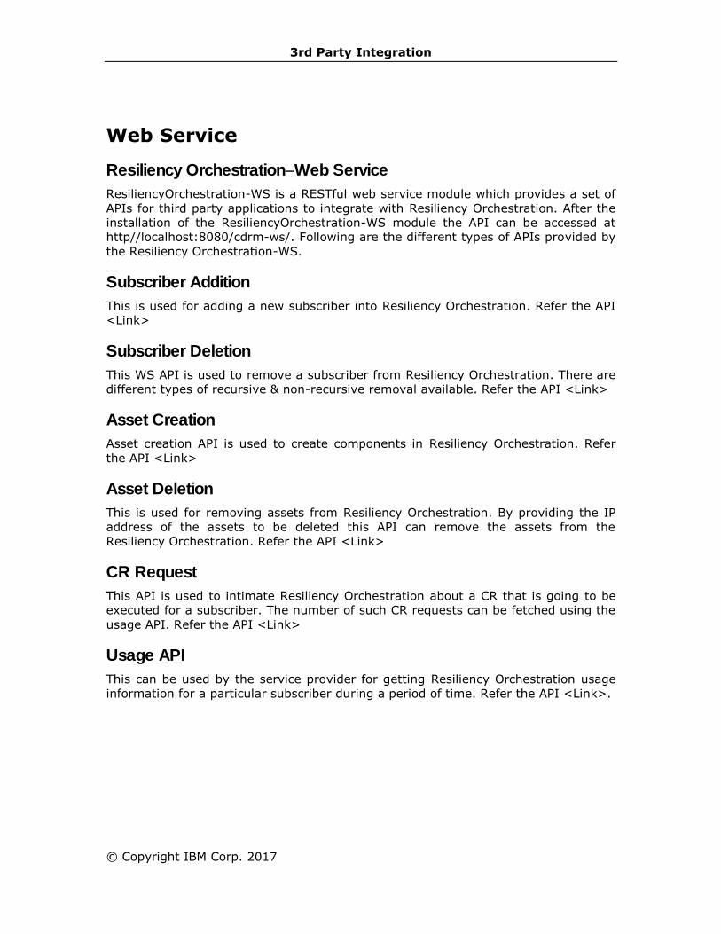
3rd Party Integration
© Copyright IBM Corp. 2017
Web Service
Resiliency Orchestration–Web Service
ResiliencyOrchestration-WS is a RESTful web service module which provides a set of
APIs for third party applications to integrate with Resiliency Orchestration. After the
installation of the ResiliencyOrchestration-WS module the API can be accessed at
http//localhost:8080/cdrm-ws/. Following are the different types of APIs provided by
the Resiliency Orchestration-WS.
Subscriber Addition
This is used for adding a new subscriber into Resiliency Orchestration. Refer the API
<Link>
Subscriber Deletion
This WS API is used to remove a subscriber from Resiliency Orchestration. There are
different types of recursive & non-recursive removal available. Refer the API <Link>
Asset Creation
Asset creation API is used to create components in Resiliency Orchestration. Refer
the API <Link>
Asset Deletion
This is used for removing assets from Resiliency Orchestration. By providing the IP
address of the assets to be deleted this API can remove the assets from the
Resiliency Orchestration. Refer the API <Link>
CR Request
This API is used to intimate Resiliency Orchestration about a CR that is going to be
executed for a subscriber. The number of such CR requests can be fetched using the
usage API. Refer the API <Link>
Usage API
This can be used by the service provider for getting Resiliency Orchestration usage
information for a particular subscriber during a period of time. Refer the API <Link>.

IBM Resiliency Orchestration Administrator’s Guide
© Copyright IBM Corp. 2017
Glossary
This section maintains a glossary of all terms used by IBM Resiliency Orchestration
designers, developers, Quality Analyst and documentation. Please refer this section
for any clarifications regarding IBM Resiliency Orchestration related documentation.
Agent
It is a light weight IBM Resiliency Orchestration Software Component that runs on a
customer application server to manage a specific object (dataset, service, or
component).
Business Continuity Mode (BCM)
Represents the current state of an Availability Group whose data is protected. Typical
Modes are: Normal, Failover, and Fallback.
Business Continuity Solution (BCS)
A data management solution that provides the capability to protect the Production
Data of a Business Application at an Alternate Site (called DR site) during normal
conditions
In case of a disaster where the production site went down, provides the capability to
recover the application to as current data as possible on the Alternate Site within the
specified Recovery objectives.
BCS Module
It is a IBM Resiliency Orchestration Software Component that runs on the IBM
Resiliency Orchestration Master Server and provides Enterprise Continuity Solution
intelligence of different type of Solutions for a specific database or file-system.
Component
It is an infrastructure object such as a Windows Server that participates in a Disaster
Recovery Solution.
Current Primary Server
The database server functioning as a production server for time being is called
current primary or production server. The data gets replicated from this server to the
current DR server.
Current Primary Site

Glossary
© Copyright IBM Corp. 2017
The location of the current production server is called the current primary site.
Configured DR Server
The database server initially configured to store the backup of the data replicating
from the primary server is known as configured DR server. This server is located at a
different location and is also called as remote or secondary server.
Configured DR Site
The location of the configured DR server is called the configured DR site.
Current DR Server
The database server functioning as a DR server for time being is called current DR
server. This server backs up of the data replicated from the current primary server
and is located at a different location.
Current DR Site
The location of the current DR server is called the current DR site.
Recovery Group
Representation of a DR solution comprising of Datasets, Protection Scheme and
Components, inter-dependency of these along with other solution parameters of a
specified application (database). Typically Recovery Group is created for each
application whose data protection needs to be managed by IBM Resiliency
Orchestration.
Dataset
Indicates all related data that is the object of replication and/or management by IBM
Resiliency Orchestration. For example, for Oracle – data files, control files and
configuration files form the dataset.
Dependant Component object
A Component on which the Dataset associated to the Group under consideration is
based on is called dependant Component object.
Disaster Recovery Solution
A data management solution that provides the capability to protect the Production
Data of a Business Application at an Alternate Site (called DR site) during normal
conditions
In case of a disaster where the production site went down, provides the capability to
recover the application to as current data as possible from the data residing at the
Alternate Site, within a specified Recovery objectives.
DR (Remote) Site
A Site where a copy of the production data is transferred and maintained as a
backup copy is called DR site.
DR Server
The server residing on the remote site is called DR server. This server contains a
copy of the data (backup) of the production server. The DR server is referred as
remote server.
FIRST
IBM Resiliency Orchestration Administrator’s Guide
IBM Resiliency Orchestration provides the following feature, referred by an acronym
FIRST.
▪ F- Failover/Fallback (Continuity
▪ I - Event
▪ R – RPO/RTO
▪ S - Security (Data Protection)
▪ T - Test Exercises.
Failover operation
A BCM where the business is in the process of moving the Production to the DR site
or has moved to the DR site and executing production in the DR site. In this case,
the data protection no longer happens; only the DR site (current production) has the
latest data and the Primary site does not get updates. Starting BCM is ‘Normal’.
Fallback operation
A BCM where the business is in the process of moving Production from a DR site to
the Primary site. Starting BCM is “Failover”.
Group
Group constitutes Components, Datasets and Protection Schemes. In general group
refers to Recovery Group.
The group represents the data to the replicated (datasets), location of the data
(Component) and the mechanism used to replicate the data (Protection Scheme).
Event
A condition that leads to or causes disruption of continuous access to production
server, application or dataset.
Listener
When an instance starts, a network listener process establishes a communication
pathway to Oracle. When you process a request connection, the listener establishes
an appropriate connection.
Mounting
Associating the instance with a specific database is mounting a database
Oracle Instance
Combination of the memory called System Global Area and its associated Oracle
process is an Oracle Instance
IBM Resiliency Orchestration Master Server
It is a dedicated Server that runs the IBM Resiliency Orchestration Master software
and has the primary ownership of the entire DR infrastructure.
IBM Resiliency Orchestration Client
An end application or database server that runs one or multiple IBM Resiliency
Orchestration Agents.
Glossary
© Copyright IBM Corp. 2017
PFR
PFR - is an enterprise replication solution, embedded with EAMS product. This is used
to replicate data, make it available between nodes and protect against critical data
loss.
Primary Site
A location of the production database server.
Primary Server
The server with production database located on the primary site is called primary
server. This is also called as Production Server. The data replicates from the primary
server to the DR server.
Production Server
The server with production database is called the production server. This could be
either primary or DR server depending on BCO. During normal situations, the
production data resides at the primary server, hence the primary server is called the
production server.
Secondary Site
A location where a copy of the production data is transferred and maintained as a
backup copy is called Secondary Site.
Glossary
Asynchronous Replication
Under asynchronous replication, updates to the application on the Source server are
persistently queued to be forwarded to the Target server.
Archived Redo Log
Oracle allows you to save filled groups of online redo log files to one or more offline
destinations, known as the archived redo log.
Archiving
The process of turning online redo log files into archived redo log files is called
archiving. This process is only possible if the database is running in ARCHIVELOG
mode.
Configured Primary Server
The database server initially configured as primary (production) server. The data
volumes to be replicated reside on this server.
Configured Primary Site
The location of the configured primary server is called the configured primary site.
Current Primary Server
IBM Resiliency Orchestration Administrator’s Guide
The database server functioning as a production server for time being is called
current primary or production server. The data gets replicated from this server to the
current DR server.
Current Primary Site
The location of the current production server is called the current primary site.
Configured DR Server
The database server initially configured to store the backup of the data replicating
from the primary server is known as configured DR server. This server is located at a
different location and is also called as remote or secondary server.
Configured DR Site
The location of the configured DR server is called the configured DR site.
Current DR Server
The database server functioning as a DR server for time being is called current DR
server. This server backs up of the data replicated from the current primary server
and is located at a different location.
Current DR Site
The location of the current DR server is called the current DR site.
Cyclic Redundancy Check (CRC)
CRC is performed to check the consistency of data on two different machines,
especially used when transferring files from one location to another.
DR RVG
The Replicated Volume Group residing on the DR server is called DR RVG. This is also
referred as secondary RVG.
Online Redo Log
The online redo log file consists of two or more pre allocated files that store all
changes made to the database as they occur. Every instance of an Oracle database
has an associated online redo log to protect the database in case of an instance
failure.
Primary RVG
The Replicated Volume Group residing on the primary server is called primary RVG.
This is also referred as production RVG as primary server is known as production
server.
Source Server
The machine from which the data gets replicated is called source server. This is same
as the primary server. In replication tool (VVR) concept, the primary server is
referred as the source server
Synchronous Replication
Synchronous replication ensures that an update has been posted to the Target server
and acknowledged to the Source server before completing the update at the Source
server.

Glossary
© Copyright IBM Corp. 2017
For information on the following Oracle terms refer to the respective Oracle Guide.
▪ Control File
▪ Database Initialization File
▪ Data Volumes
▪ Password File
▪ Oracle SID
▪ Server Parameter File (SPFILE)
▪ Trace file
▪ udump
▪ cdump
▪ bdump
▪ Tablespace
Oracle’s auditing option
For information on the following VVR terms refer to the respective VERITAS Volume
Replicator Guide.
▪ Disk Group
▪ Storage Replicator Volume (SRL)
▪ Replicated Volume Group (RVG)
▪ RLINK
Target Server
The machine to which the data gets replicated from the source server is called target
server. The target server is placed at a different location and the data replicated is
maintained as a backup copy of the original data residing on the source server. The
target server is same as the DR server. In replication tool (VVR) concept, the DR
server is referred as the target server
Glossary
PIT data copy

IBM Resiliency Orchestration Administrator’s Guide
A fully usable copy of a dataset that contains an image of the data as it appeared at
a single point-in-time. The different types or implementations of Point-In-Time (PIT)
copy technology are Split Mirror, Changed Block, Concurrent, Clone, etc. The copy is
considered to have logically occurred at that point-in-time, but implementations may
perform part or all of the copy at other times as long as the result is a consistent
copy of the dataset as it appeared at that point-in-time.
Source Dataset
This is the dataset on the site that contains the Master or source image of the data.
This is the copy source for any of the PIT data copies that exist on the site.
Storage Volume
A storage volume is a LUN presented from a storage array. A storage volume is
based on physical media or a more complicated RAID configuration.

© Copyright IBM Corp. 2017
Pop-Ups
Operations Basic Advanced
Adding Drills Administrator and the Super Administrator have the privilege to create Drills.
Administrator and the Super Administrator have the privilege to create Drill. If Operator’s privilege is enhanced then, the Operator has the
privilege to create Drills.
Operations Basic Advanced
Adding Business Process
Administrator and the Super Administrator have the privilege to create Business Process.
Administrator and the Super Administrator have the privilege to create Business Process. If the
operator's role is enhanced then, operator has an additional privilege to create Business Process.
Operations Basic Advanced
Adding Management Service
Administrator and the Super Administrator have the privilege to add the management service.
Administrator and the Super Administrator
have the privilege to add the management
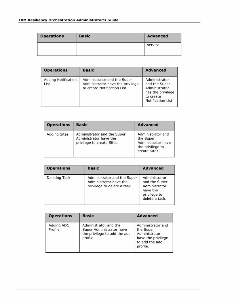
IBM Resiliency Orchestration Administrator’s Guide
Operations Basic Advanced
service.
Operations Basic Advanced
Adding Notification List
Administrator and the Super Administrator have the privilege to create Notification List.
Administrator and the Super Administrator has the privilege
to create Notification List.
Operations Basic Advanced
Adding Sites Administrator and the Super Administrator have the
privilege to create Sites.
Administrator and the Super
Administrator have the privilege to create Sites.
Operations Basic Advanced
Deleting Task Administrator and the Super Administrator have the privilege to delete a task.
Administrator and the Super Administrator have the
privilege to delete a task.
Operations Basic Advanced
Adding ADC Profile
Administrator and the Super Administrator have the privilege to add the adc profile.
Administrator and the Super Administrator have the privilege
to add the adc profile.

Pop-Ups
© Copyright IBM Corp. 2017
Operations Basic Advanced
Adding Users Super Administrator has the privilege to create Users.
NA.
Operations Basic Advanced
Adding UCS Director Administrator and the Super Administrator have the privilege to add UCS Director.
Administrator and the Super Administrator have the privilege to add UCS
Director.
Operations Basic Advanced
Adding UCS Director vDC Map
Administrator and the Super Administrator have the privilege to add UCS Director DR Map.
Administrator and the Super Administrator have the privilege to add UCS Director DR Map.
Operations Basic Advanced
Agent listing Operator, Administrator and Super Administrator have the privilege to read the details related to Agents.
Operator, Administrator and Super Administrator have the privilege to read the details related to Agents.
AWS agent
An AWS Agent helps in connecting AWS Server and is auto created when a management
service is created.
Below listed is the Event Configuration for an AWS agent:
Event ID Severity Description Impact
AWSAgentDownEvent CRITICAL AWS Agent is down
Resources Managed by AWS cannot be Managed/ Monitored
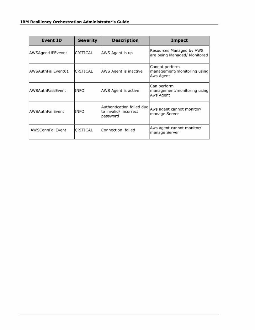
IBM Resiliency Orchestration Administrator’s Guide
Event ID Severity Description Impact
AWSAgentUPEvevnt CRITICAL AWS Agent is up Resources Managed by AWS are being Managed/ Monitored
AWSAuthFailEvent01 CRITICAL AWS Agent is inactive Cannot perform management/monitoring using Aws Agent
AWSAuthPassEvent INFO AWS Agent is active Can perform management/monitoring using Aws Agent
AWSAuthFailEvent INFO Authentication failed due to invalid/ incorrect password
Aws agent cannot monitor/ manage Server
AWSConnFailEvent CRITICAL Connection failed Aws agent cannot monitor/ manage Server
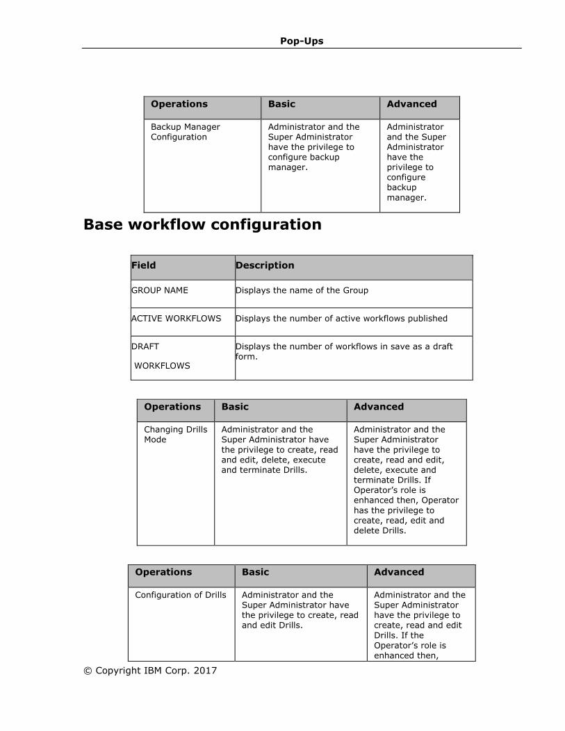
Pop-Ups
© Copyright IBM Corp. 2017
Operations Basic Advanced
Backup Manager Configuration
Administrator and the Super Administrator have the privilege to configure backup manager.
Administrator and the Super Administrator have the privilege to configure backup
manager.
Base workflow configuration
Field Description
GROUP NAME Displays the name of the Group
ACTIVE WORKFLOWS Displays the number of active workflows published
DRAFT
WORKFLOWS
Displays the number of workflows in save as a draft form.
Operations Basic Advanced
Changing Drills Mode
Administrator and the Super Administrator have
the privilege to create, read and edit, delete, execute and terminate Drills.
Administrator and the Super Administrator
have the privilege to create, read and edit, delete, execute and terminate Drills. If Operator’s role is enhanced then, Operator
has the privilege to create, read, edit and delete Drills.
Operations Basic Advanced
Configuration of Drills Administrator and the Super Administrator have the privilege to create, read and edit Drills.
Administrator and the Super Administrator have the privilege to create, read and edit
Drills. If the Operator’s role is enhanced then,

IBM Resiliency Orchestration Administrator’s Guide
Operations Basic Advanced
Operator has the privilege to read, create and edit Drills.
Listing Organizations
Organizations are listed to bring contextual data published across all the IBM Resiliency
Orchestration pages. When an organization is selected, all the pages render only the groups
that belong to that particular Organization. By default, a 'Default' organization is created, any
group that will be created will belong to 'Default' Organization.
The Organization details are listed below:
NAME Description
ORGANIZATION ID Displays the Organization ID.
ORGANIZATION NAME Displays the Organization name configured with IBM Resiliency Orchestration.
DESCRIPTION Displays the description of the organization.
MANAGED GROUPS Displays the number of groups managed by the organization.
UNMANAGED GROUPS Displays the number of groups not managed by the organization.
CREATED SINCE Displays the Time stamp of the organization .
Operations Basic Advanced
Configuring Business process
Administrator and Super Administrator have the privilege to edit/update the Business Process.
Administrator and Super Administrator have the privilege to edit/update the Business Process. If the operator's role is enhanced then,
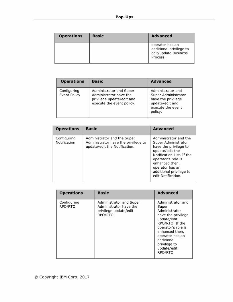
Pop-Ups
© Copyright IBM Corp. 2017
Operations Basic Advanced
operator has an additional privilege to edit/update Business Process.
Operations Basic Advanced
Configuring
Event Policy
Administrator and Super
Administrator have the privilege update/edit and execute the event policy.
Administrator and
Super Administrator have the privilege update/edit and execute the event policy.
Operations Basic Advanced
Configuring Notification
Administrator and the Super Administrator have the privilege to update/edit the Notification.
Administrator and the Super Administrator have the privilege to update/edit the Notification List. If the
operator's role is enhanced then,
operator has an additional privilege to edit Notification.
Operations Basic Advanced
Configuring RPO/RTO
Administrator and Super Administrator have the privilege update/edit
RPO/RTO.
Administrator and Super Administrator
have the privilege update/edit
RPO/RTO. If the operator's role is enhanced then, operator has an additional
privilege to update/edit RPO/RTO.

IBM Resiliency Orchestration Administrator’s Guide
Operations Basic Advanced
Configuring Notification
regarding Events
Administrator and the Super Administrator has the privilege to
update/edit the Notification .
Administrator and the Super Administrator has the
privilege to update/edit the Notification List. If the operator's role is enhanced then, operator has the additional privilege to edit Notification.
Operations Basic Advanced
Configuring WAN Agents
Administrator and the Super Administrator have the privilege to update/edit the
Agents.
Administrator and the Super Administrator have
the privilege to update/edit the Agents.
Flexi Functional Group
Flexi FG (Flexible Functional Group) is a feature with in Pumice which allows user to create
group without selecting any subsystem. Before the pumice version the user when creating
the group was asked to select all the subsystems (components, dataset & protection
scheme).
Currently the Flexi FG group are only supported for two Solution Signature and those are
1 VM Replication On Flexpod
2 Stateless application for AWS
As part of the feature only dataset masking has been provided were in when any of the
above solutions are selected the user need not select the dataset as part of group creation,
he will only have to provide components and protection scheme paring.
Operations Basic Advanced
Creating Groups
Administrator and the Super Administrator have the privilege to create
Groups.
Administrator and the Super Administrator
have the privilege to create Groups. If the operator's role is enhanced then, operator
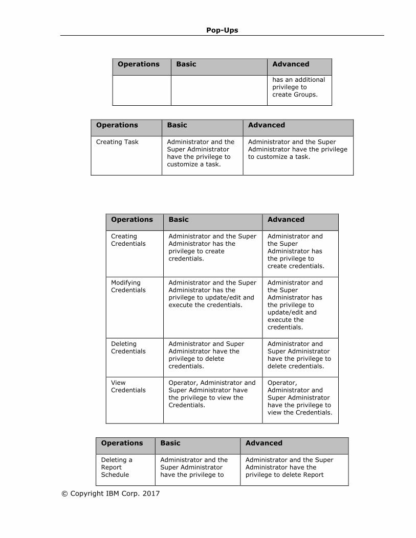
Pop-Ups
© Copyright IBM Corp. 2017
Operations Basic Advanced
has an additional privilege to create Groups.
Operations Basic Advanced
Creating Task Administrator and the Super Administrator have the privilege to
customize a task.
Administrator and the Super Administrator have the privilege to customize a task.
Operations Basic Advanced
Creating Credentials
Administrator and the Super Administrator has the
privilege to create credentials.
Administrator and the Super
Administrator has the privilege to create credentials.
Modifying Credentials
Administrator and the Super Administrator has the privilege to update/edit and execute the credentials.
Administrator and the Super Administrator has the privilege to update/edit and execute the credentials.
Deleting Credentials
Administrator and Super Administrator have the privilege to delete
credentials.
Administrator and Super Administrator have the privilege to
delete credentials.
View Credentials
Operator, Administrator and Super Administrator have
the privilege to view the Credentials.
Operator, Administrator and
Super Administrator have the privilege to view the Credentials.
Operations Basic Advanced
Deleting a Report Schedule
Administrator and the Super Administrator have the privilege to
Administrator and the Super Administrator have the privilege to delete Report
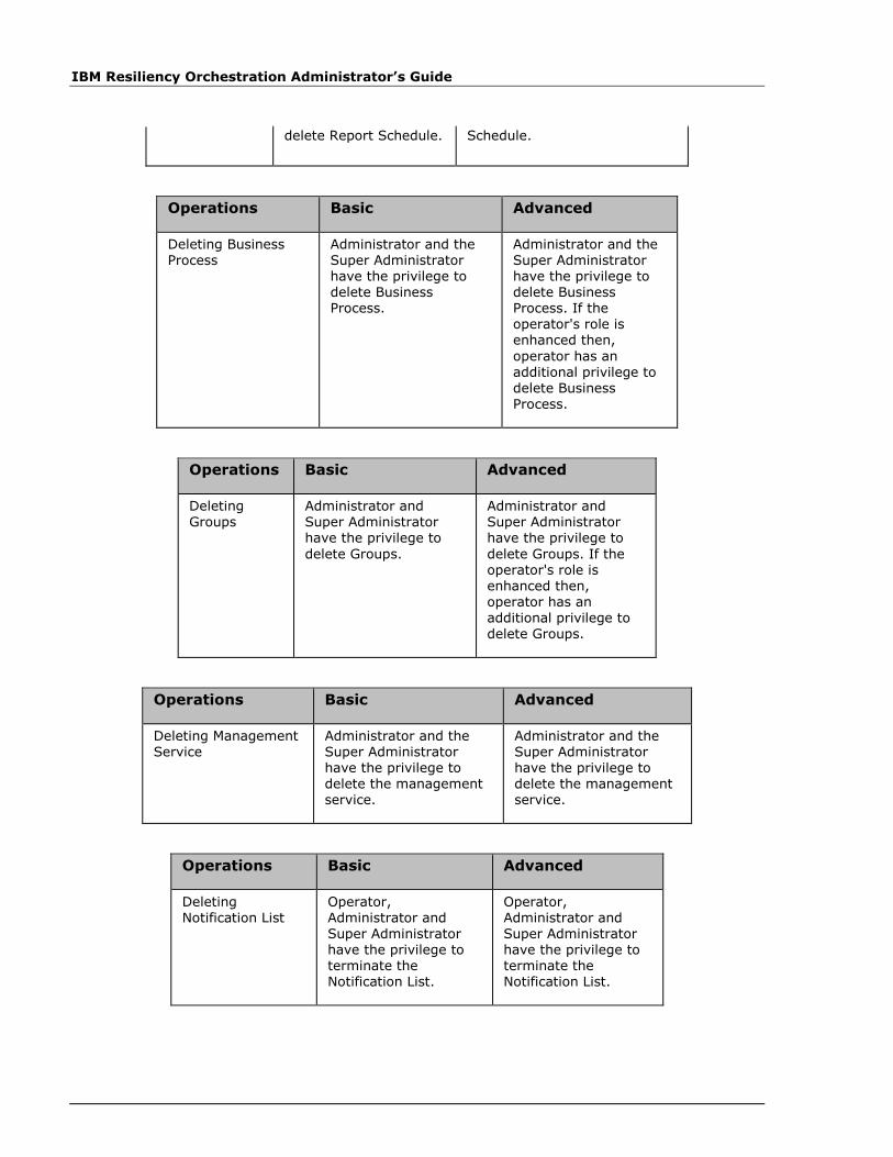
IBM Resiliency Orchestration Administrator’s Guide
delete Report Schedule. Schedule.
Operations Basic Advanced
Deleting Business Process
Administrator and the Super Administrator have the privilege to delete Business Process.
Administrator and the Super Administrator have the privilege to delete Business Process. If the operator's role is enhanced then,
operator has an
additional privilege to delete Business Process.
Operations Basic Advanced
Deleting Groups
Administrator and Super Administrator have the privilege to
delete Groups.
Administrator and Super Administrator have the privilege to
delete Groups. If the operator's role is enhanced then, operator has an
additional privilege to delete Groups.
Operations Basic Advanced
Deleting Management Service
Administrator and the Super Administrator have the privilege to delete the management service.
Administrator and the Super Administrator have the privilege to delete the management service.
Operations Basic Advanced
Deleting Notification List
Operator, Administrator and Super Administrator have the privilege to terminate the Notification List.
Operator, Administrator and Super Administrator have the privilege to terminate the Notification List.
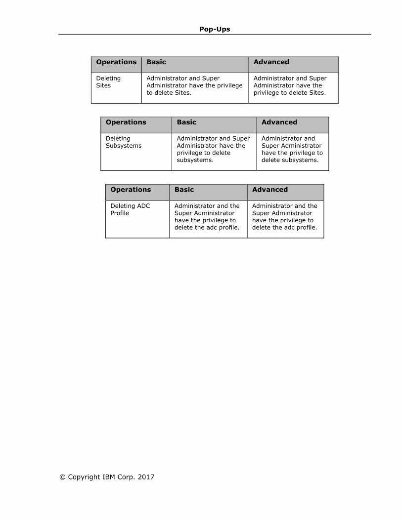
Pop-Ups
© Copyright IBM Corp. 2017
Operations Basic Advanced
Deleting Sites
Administrator and Super Administrator have the privilege
to delete Sites.
Administrator and Super Administrator have the
privilege to delete Sites.
Operations Basic Advanced
Deleting Subsystems
Administrator and Super Administrator have the privilege to delete subsystems.
Administrator and Super Administrator have the privilege to delete subsystems.
Operations Basic Advanced
Deleting ADC Profile
Administrator and the Super Administrator have the privilege to delete the adc profile.
Administrator and the Super Administrator have the privilege to delete the adc profile.
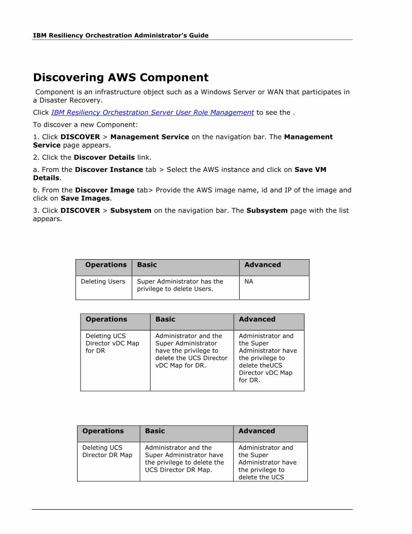
IBM Resiliency Orchestration Administrator’s Guide
Discovering AWS Component
Component is an infrastructure object such as a Windows Server or WAN that participates in
a Disaster Recovery.
Click IBM Resiliency Orchestration Server User Role Management to see the .
To discover a new Component:
1. Click DISCOVER > Management Service on the navigation bar. The Management
Service page appears.
2. Click the Discover Details link.
a. From the Discover Instance tab > Select the AWS instance and click on Save VM
Details.
b. From the Discover Image tab> Provide the AWS image name, id and IP of the image and
click on Save Images.
3. Click DISCOVER > Subsystem on the navigation bar. The Subsystem page with the list
appears.
Operations Basic Advanced
Deleting Users Super Administrator has the privilege to delete Users.
NA
Operations Basic Advanced
Deleting UCS Director vDC Map for DR
Administrator and the Super Administrator have the privilege to delete the UCS Director vDC Map for DR.
Administrator and the Super Administrator have the privilege to delete theUCS Director vDC Map for DR.
Operations Basic Advanced
Deleting UCS Director DR Map
Administrator and the Super Administrator have the privilege to delete the
UCS Director DR Map.
Administrator and the Super Administrator have
the privilege to delete the UCS
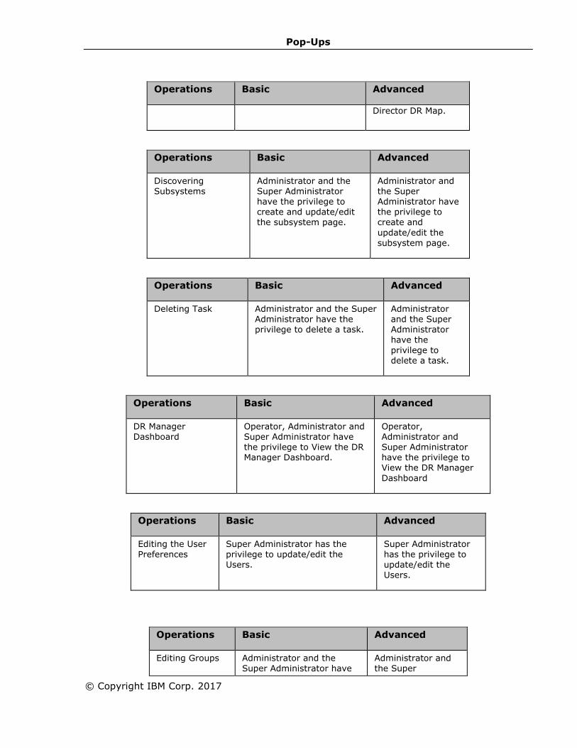
Pop-Ups
© Copyright IBM Corp. 2017
Operations Basic Advanced
Director DR Map.
Operations Basic Advanced
Discovering Subsystems
Administrator and the Super Administrator have the privilege to create and update/edit the subsystem page.
Administrator and the Super Administrator have the privilege to create and
update/edit the
subsystem page.
Operations Basic Advanced
Deleting Task Administrator and the Super Administrator have the privilege to delete a task.
Administrator and the Super Administrator have the
privilege to delete a task.
Operations Basic Advanced
DR Manager Dashboard
Operator, Administrator and Super Administrator have the privilege to View the DR Manager Dashboard.
Operator, Administrator and Super Administrator have the privilege to View the DR Manager
Dashboard
Operations Basic Advanced
Editing the User
Preferences
Super Administrator has the
privilege to update/edit the Users.
Super Administrator
has the privilege to update/edit the Users.
Operations Basic Advanced
Editing Groups Administrator and the Super Administrator have
Administrator and the Super
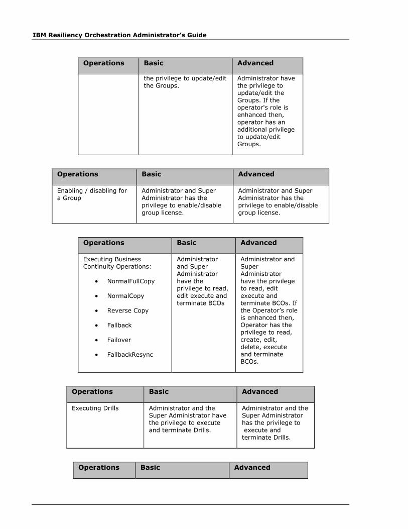
IBM Resiliency Orchestration Administrator’s Guide
Operations Basic Advanced
the privilege to update/edit the Groups.
Administrator have the privilege to update/edit the Groups. If the operator's role is enhanced then,
operator has an additional privilege to update/edit Groups.
Operations Basic Advanced
Enabling / disabling for a Group
Administrator and Super Administrator has the privilege to enable/disable
group license.
Administrator and Super Administrator has the privilege to enable/disable
group license.
Operations Basic Advanced
Executing Business Continuity Operations:
• NormalFullCopy
• NormalCopy
• Reverse Copy
• Fallback
• Failover
• FallbackResync
Administrator and Super Administrator
have the privilege to read,
edit execute and terminate BCOs
Administrator and Super Administrator
have the privilege to read, edit
execute and terminate BCOs. If the Operator’s role is enhanced then, Operator has the privilege to read, create, edit,
delete, execute and terminate BCOs.
Operations Basic Advanced
Executing Drills Administrator and the Super Administrator have the privilege to execute
and terminate Drills.
Administrator and the Super Administrator has the privilege to
execute and terminate Drills.
Operations Basic Advanced
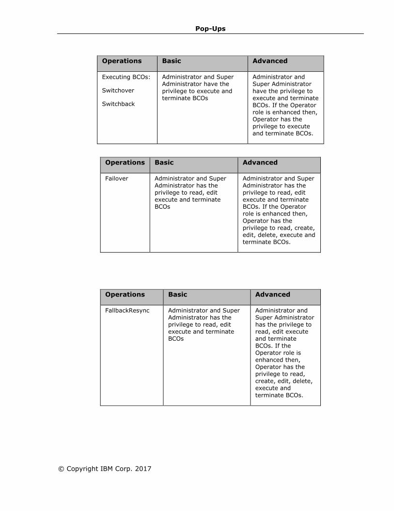
Pop-Ups
© Copyright IBM Corp. 2017
Operations Basic Advanced
Executing BCOs:
Switchover
Switchback
Administrator and Super Administrator have the
privilege to execute and terminate BCOs
Administrator and Super Administrator
have the privilege to execute and terminate BCOs. If the Operator role is enhanced then, Operator has the privilege to execute and terminate BCOs.
Operations Basic Advanced
Failover Administrator and Super Administrator has the privilege to read, edit execute and terminate BCOs
Administrator and Super Administrator has the privilege to read, edit execute and terminate BCOs. If the Operator role is enhanced then,
Operator has the privilege to read, create, edit, delete, execute and terminate BCOs.
Operations Basic Advanced
FallbackResync Administrator and Super Administrator has the privilege to read, edit execute and terminate BCOs
Administrator and Super Administrator has the privilege to read, edit execute and terminate
BCOs. If the Operator role is enhanced then, Operator has the privilege to read,
create, edit, delete, execute and
terminate BCOs.
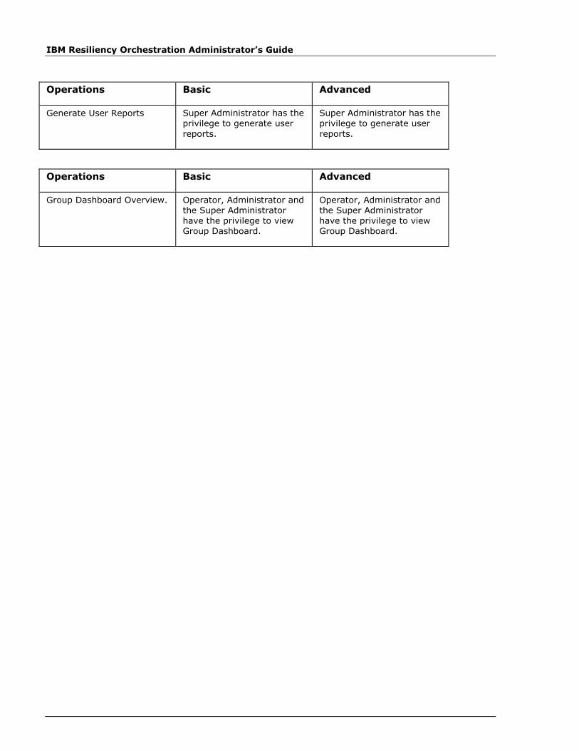
IBM Resiliency Orchestration Administrator’s Guide
Operations Basic Advanced
Generate User Reports Super Administrator has the privilege to generate user
reports.
Super Administrator has the privilege to generate user
reports.
Operations Basic Advanced
Group Dashboard Overview. Operator, Administrator and the Super Administrator have the privilege to view Group Dashboard.
Operator, Administrator and the Super Administrator have the privilege to view Group Dashboard.

Pop-Ups
© Copyright IBM Corp. 2017
Operations Basic Advanced
Group Maintenance Administrator and the Super Administrator have the privilege to maintain the Groups.
Administrator and the Super Administrator have the privilege to maintain the Groups. If the operator's role is enhanced then,
operator has an additional privilege to update/edit Groups.
Group Level configuration
Group levels are configured and listed based on the users priority.
Default Group Labels are listed as below:
ID LABEL
1 TYPE I
2 TYPE II
3 TYPE III
4 TYPE IV
1. Click Save, to save the lD and its group label.
Operations Basic Advanced
Listing Business Process schedule
Operator, Administrator and the Super Administrator have the privilege to view the details related to Business Process.
Operator, Administrator and the Super Administrator have the privilege to view the details related to Business Process.

IBM Resiliency Orchestration Administrator’s Guide
Operations Basic Advanced
Listing Log Files Administrator and the Super Administrator have the privilege to read the log files.
Administrator and the Super Administrator have the privilege to read the log files.
Operations Basic Advanced
Listing Management Service Administrator and the Super
Administrator have the
privilege to read the details related to management service.
Administrator and the Super
Administrator have the
privilege to read the details related to management service.
Operations Basic Advanced
Listing Task Tthe Super Administrator, Administrator and the operator have the privilege to read a task.
Tthe Super Administrator, Administrator and the operator have the privilege to read a task.
Operations Basic Advanced
Listing ADC Profile Administrator and the Super Administrator have the privilege to read the details related to an adc profile.
Administrator and the Super Administrator have the privilege to read the details related to an adc profile.
Operations Basic Advanced
Listing Subsystem Operator, Administrator and Super Administrator have
the privilege to read details
related to Subsystem.
Operator, Administrator and Super Administrator have
the privilege to read details
related to Subsystem.
Operations Basic Advanced
Listing UCS Director Administrator and the Super Administrator have the privilege to read the details related to UCS Director.
Administrator and the Super Administrator have the privilege to read the details related to UCS Director.

Pop-Ups
© Copyright IBM Corp. 2017
Operations Basic Advanced
Listing UCS Director DR Map
Administrator and the Super Administrator have the privilege to read the UCS Director DR Map.
Administrator and the Super Administrator have the privilege to read the UCS Director DR Map.
Operations Basic Advanced
Listing Task Administrator and the Super Administrator have the
privilege to read a task.
Administrator and the Super Administrator have the
privilege to read a task..
Operations Basic Advanced
Managing Business Process Administrator and Super Administrator have the privilege to edit/update the Business Process.
Administrator and Super Administrator have the privilege to edit/update the Business Process. If the operator's role is enhanced then, operator has an additional privilege to edit/update the Business
Process.
Operations Basic Advanced
Modifying Management Service
Administrator and the Super Administrator have the privilege to update/edit the management service.
Administrator and the Super Administrator have the privilege to update/edit the management service .
Operations Basic Advanced
Modifying ADC Profile Administrator and the Super Administrator have the privilege to update/edit an
adc profile.
Administrator and the Super Administrator have the privilege to update/edit an
adc profile.
Operations Basic Advanced
Modifying Report Schedule Administrator and the Super Administrator has the privilege to Report
Administrator and the Super Administrator has the privilege to Report
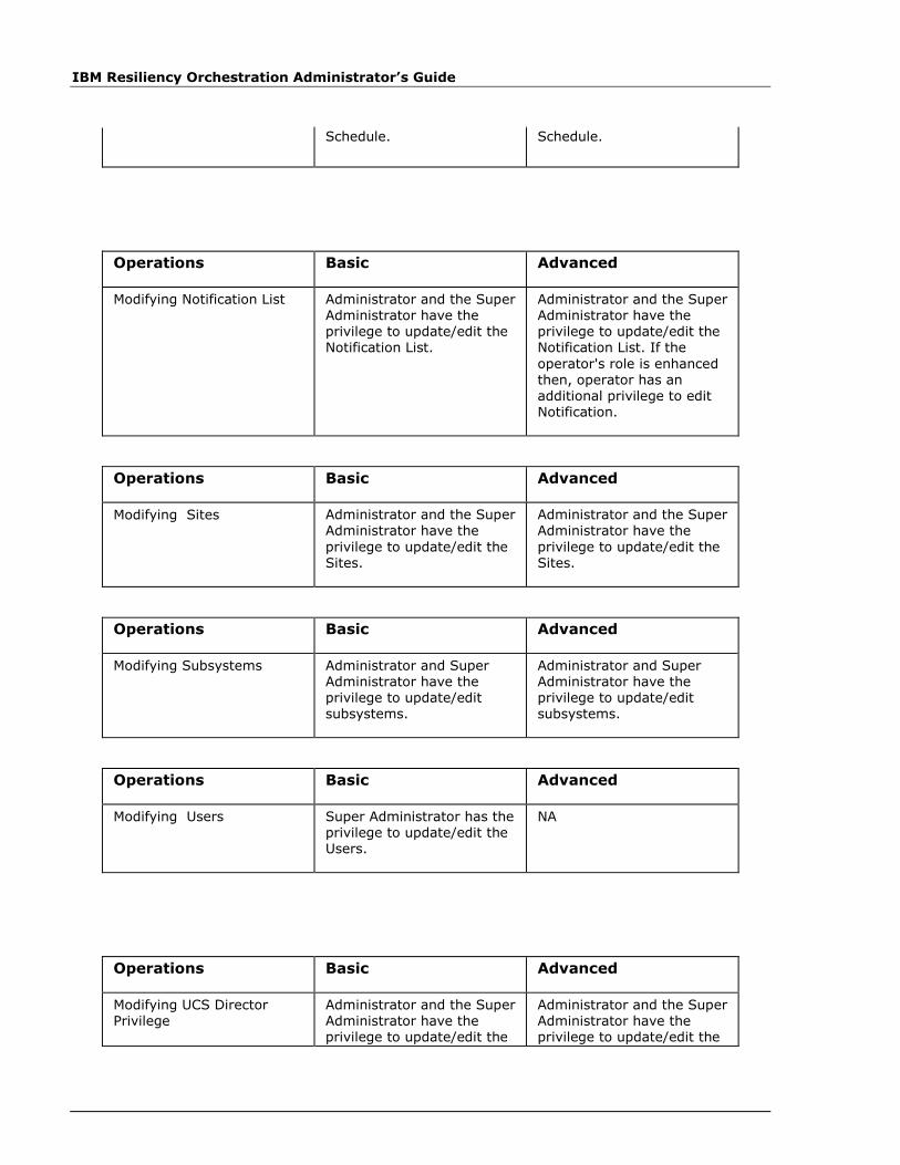
IBM Resiliency Orchestration Administrator’s Guide
Schedule. Schedule.
Operations Basic Advanced
Modifying Notification List Administrator and the Super Administrator have the privilege to update/edit the Notification List.
Administrator and the Super Administrator have the privilege to update/edit the Notification List. If the
operator's role is enhanced
then, operator has an additional privilege to edit Notification.
Operations Basic Advanced
Modifying Sites Administrator and the Super Administrator have the
privilege to update/edit the Sites.
Administrator and the Super Administrator have the
privilege to update/edit the Sites.
Operations Basic Advanced
Modifying Subsystems Administrator and Super Administrator have the privilege to update/edit subsystems.
Administrator and Super Administrator have the privilege to update/edit subsystems.
Operations Basic Advanced
Modifying Users Super Administrator has the privilege to update/edit the Users.
NA
Operations Basic Advanced
Modifying UCS Director Privilege
Administrator and the Super Administrator have the privilege to update/edit the
Administrator and the Super Administrator have the privilege to update/edit the

Pop-Ups
© Copyright IBM Corp. 2017
Operations Basic Advanced
UCS Director. UCS Director.
Operations Basic Advanced
Modifying Task Administrator and the Super Administrator have the privilege to edit/update a task.
Administrator and the Super Administrator have the privilege to edit/update a task.
Operations Basic Advanced
Monitoring Groups Operator, Administrator and the Super Administrator have the privilege to Monitor
Groups
Operator, Administrator and the Super Administrator have the privilege to Monitor
Groups
Operations Basic Advanced
NormalFullCopy Administrator and Super Administrator has the privilege to read, edit
execute and terminate BCOs
Administrator and Super Administrator has the privilege to read, edit
execute and terminate BCOs. If the Operator role is enhanced then, Operator has the privilege to read, create, edit, delete, execute and terminate BCOs.
Operations Basic Advanced
Operational Dashboard Operator, Administrator and Super Administrator have the privilege to View the Operational Dashboard.
Operator, Administrator and Super Administrator have the privilege to View the Operational Dashboard.
Operations Basic Advanced
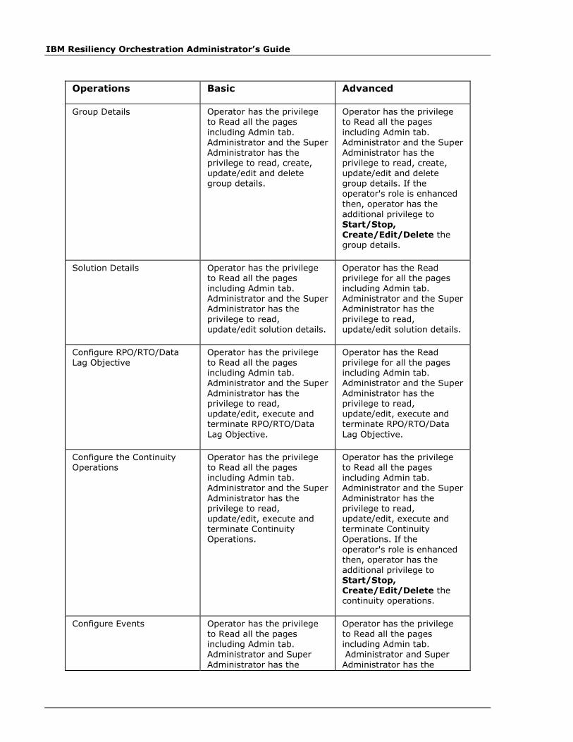
IBM Resiliency Orchestration Administrator’s Guide
Operations Basic Advanced
Group Details
Operator has the privilege to Read all the pages
including Admin tab. Administrator and the Super Administrator has the privilege to read, create, update/edit and delete group details.
Operator has the privilege to Read all the pages
including Admin tab. Administrator and the Super Administrator has the privilege to read, create, update/edit and delete group details. If the operator's role is enhanced
then, operator has the additional privilege to Start/Stop,
Create/Edit/Delete the group details.
Solution Details Operator has the privilege to Read all the pages including Admin tab. Administrator and the Super Administrator has the
privilege to read, update/edit solution details.
Operator has the Read privilege for all the pages including Admin tab. Administrator and the Super Administrator has the
privilege to read, update/edit solution details.
Configure RPO/RTO/Data Lag Objective
Operator has the privilege to Read all the pages including Admin tab. Administrator and the Super
Administrator has the privilege to read, update/edit, execute and terminate RPO/RTO/Data
Lag Objective.
Operator has the Read privilege for all the pages including Admin tab. Administrator and the Super
Administrator has the privilege to read, update/edit, execute and terminate RPO/RTO/Data
Lag Objective.
Configure the Continuity Operations
Operator has the privilege to Read all the pages
including Admin tab. Administrator and the Super Administrator has the privilege to read, update/edit, execute and terminate Continuity Operations.
Operator has the privilege to Read all the pages
including Admin tab. Administrator and the Super Administrator has the privilege to read, update/edit, execute and terminate Continuity Operations. If the
operator's role is enhanced then, operator has the additional privilege to Start/Stop, Create/Edit/Delete the continuity operations.
Configure Events Operator has the privilege to Read all the pages including Admin tab. Administrator and Super
Administrator has the
Operator has the privilege to Read all the pages including Admin tab. Administrator and Super
Administrator has the
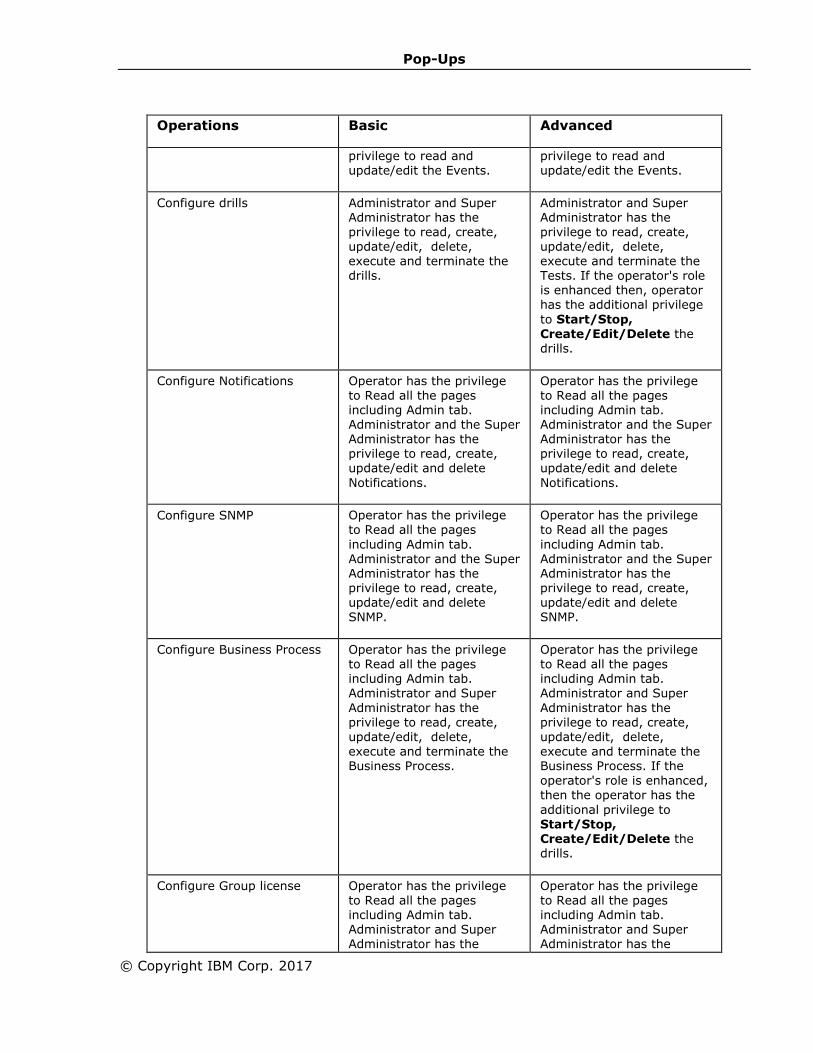
Pop-Ups
© Copyright IBM Corp. 2017
Operations Basic Advanced
privilege to read and update/edit the Events.
privilege to read and update/edit the Events.
Configure drills Administrator and Super Administrator has the privilege to read, create, update/edit, delete, execute and terminate the drills.
Administrator and Super Administrator has the privilege to read, create, update/edit, delete, execute and terminate the Tests. If the operator's role is enhanced then, operator has the additional privilege
to Start/Stop,
Create/Edit/Delete the drills.
Configure Notifications Operator has the privilege to Read all the pages including Admin tab. Administrator and the Super Administrator has the privilege to read, create, update/edit and delete
Notifications.
Operator has the privilege to Read all the pages including Admin tab. Administrator and the Super Administrator has the privilege to read, create, update/edit and delete
Notifications.
Configure SNMP Operator has the privilege to Read all the pages
including Admin tab.
Administrator and the Super Administrator has the privilege to read, create, update/edit and delete SNMP.
Operator has the privilege to Read all the pages
including Admin tab.
Administrator and the Super Administrator has the privilege to read, create, update/edit and delete SNMP.
Configure Business Process Operator has the privilege to Read all the pages including Admin tab. Administrator and Super
Administrator has the privilege to read, create, update/edit, delete, execute and terminate the Business Process.
Operator has the privilege to Read all the pages including Admin tab. Administrator and Super
Administrator has the privilege to read, create, update/edit, delete, execute and terminate the Business Process. If the
operator's role is enhanced, then the operator has the
additional privilege to Start/Stop, Create/Edit/Delete the drills.
Configure Group license Operator has the privilege to Read all the pages including Admin tab. Administrator and Super Administrator has the
Operator has the privilege to Read all the pages including Admin tab. Administrator and Super Administrator has the
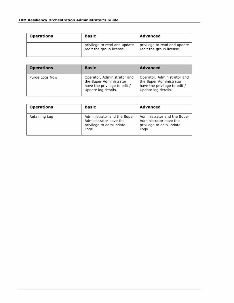
IBM Resiliency Orchestration Administrator’s Guide
Operations Basic Advanced
privilege to read and update /edit the group license.
privilege to read and update /edit the group license.
Operations Basic Advanced
Purge Logs Now Operator, Administrator and the Super Administrator
have the privilege to edit / Update log details.
Operator, Administrator and the Super Administrator
have the privilege to edit / Update log details.
Operations Basic Advanced
Retaining Log Administrator and the Super Administrator have the privilege to edit/update Logs.
Administrator and the Super Administrator have the privilege to edit/update Logs

Pop-Ups
© Copyright IBM Corp. 2017
Re-Discovering MySQL Dataset
1. Execute AGTestClient.sh script and type “rediscover”.
2. It prompt you to subsystem that you want to rediscover .i.e. Enter Sub system name
MySQL.
3. Enter dataset or protection schema name to be rediscovered
4. It shows the re-discovered items in output.
4. Also CLI shows the differences in the protection schema properties after rediscovery
5. It prompts whether you want to save the re-discovered details. Option are y/n.
6. If choice is y, then re-discovered data will be saved and refreshing of the dataset page
shows the updated details.

IBM Resiliency Orchestration Administrator’s Guide
Re-Discovering SRDF Protection Scheme
Rediscovery is a capability by which user can rediscover component/dataset/protection
schema which are already discovered and added in group. CLI to rediscover the dataset are
available under $EAMSROOT/IBMUtil/AG/AGTestClient.sh
1. Execute AGTestClient.sh script and type “rediscover”.
2. It prompt you to subsystem that you want to rediscover .i.e. Enter Sub system name
SRDF
3. Enter dataset or protection schema name to be rediscovered
4. It shows the re-discovered items in output.
4. Also CLI shows the differences in the protection schema properties after rediscovery
5. It prompts whether you want to save the re-discovered details. Option are y/n.
6. If choice is y, then re-discovered data will be saved and refreshing of the dataset page
shows the updated details.
Re-Discovering DB2 Dataset
1. Execute AGTestClient.sh script and type “rediscover”.
2. It prompt you to subsystem that you want to rediscover .i.e. Enter Sub system name DB2.
3. Enter dataset or protection schema name to be rediscovered
4. It shows the re-discovered items in output.
4. Also CLI shows the differences in the protection schema properties after rediscovery
5. It prompts whether you want to save the re-discovered details. Option are y/n.
6. If choice is y, then re-discovered data will be saved and refreshing of the dataset page
shows the updated details.
Pop-Ups
© Copyright IBM Corp. 2017
Re-Discovering MSSQL Dataset
1. Execute AGTestClient.sh script and type “rediscover”.
2. It prompt you to subsystem that you want to rediscover .i.e. Enter Sub system name
MSSQL.
3. Enter dataset or protection schema name to be rediscovered
4. It shows the re-discovered items in output.
4. Also CLI shows the differences in the protection schema properties after rediscovery
5. It prompts whether you want to save the re-discovered details. Option are y/n.
6. If choice is y, then re-discovered data will be saved and refreshing of the dataset page
shows the updated details.
Re-Discovering Sybase Dataset
1. Execute AGTestClient.sh script and type “rediscover”.
2. It prompt you to subsystem that you want to rediscover .i.e. Enter Sub system name
Sybase
3. Enter dataset or protection schema name to be rediscovered
4. It shows the re-discovered items in output.
4. Also CLI shows the differences in the protection schema properties after rediscovery
5. It prompts whether you want to save the re-discovered details. Option are y/n.
6. If choice is y, then re-discovered data will be saved and refreshing of the dataset page
shows the updated details.

IBM Resiliency Orchestration Administrator’s Guide
Re-discovering Oracle Dataset
1. Execute AGTestClient.sh script and type “rediscover”.
2. It prompt you to subsystem that you want to rediscover .i.e. Enter Sub system name
Oracle.
3. Enter dataset or protection schema name to be rediscovered
4. It shows the re-discovered items in output.
4. Also CLI shows the differences in the protection schema properties after rediscovery
5. It prompts whether you want to save the re-discovered details. Option are y/n.
6. If choice is y, then re-discovered data will be saved and refreshing of the dataset page
shows the updated details.
Operations Basic Advanced
Removing Test Exercise Administrator and the Super Administrator have the privilege to remove the Test Exercise.
Administrator and the Super Administrator have the privilege to remove the Test Exercise. If Operator’s
privilege is enhanced then, the Operator has the
privilege to create Test Exercise.
Pop-Ups
© Copyright IBM Corp. 2017
Re-discovering PostgreSQL Dataset
Rediscovery is a capability by which user can rediscover component/dataset/protection
schema which are already discovered and added in group. CLI to rediscover the dataset are
available under $EAMSROOT/IBMUtil/AG/AGTestClient.sh
1. Execute AGTestClient.sh script and type “rediscover”.
2. It prompt you to subsystem that you want to rediscover .i.e. Enter Sub system name
PostgresSQL
3. Enter dataset or protection schema name to be rediscovered
4. It shows the re-discovered items in output.
4. Also CLI shows the differences in the protection schema properties after rediscovery
5. It prompts whether you want to save the re-discovered details. Option are y/n.
6. If choice is y, then re-discovered data will be saved and refreshing of the dataset page
shows the updated details.
Discovering HP 3PAR Protection Scheme
Refer to Discovering Protection Scheme to navigate and to configure the generic details for
discovering protection scheme.
A Protection Scheme is any protection mechanism that protects data. You should discover
the component and dataset before proceeding with the protection scheme discovery.
Note
If these subsystems are discovered, but their associated agents are not connected, the
subsystems status would be shown as Unknown. When agents will be connected, the status
will be updated with status of underlying system.
To discover a new Protection Scheme, perform following steps:
1. Click DISCOVER > Subsystems on the navigation bar. The Subsystems
page appears.
2. Select HP 3PAR from the Create New drop-down list at the top right corner
of the Subsystems page. The drop-down list displays all the Protection
Schemes that can be created.
3. Click Go. The Protection Scheme Discovery page appears and the
Subsystems side bar page displays list of all the Protection Schemes
discovered.
Provide necessary information on the following fields to configure Protection Scheme.

IBM Resiliency Orchestration Administrator’s Guide
Field Description
Type Displays the type of protection scheme.
The protection scheme is displayed only if its agent is connected to the IBM Resiliency Orchestration
server. This is applicable for all protection schemes except for the one that requires manual discovery.
Name
Enter a unique name for protection scheme.
This field accepts alphanumeric characters, and underscores and the name must start with an
alphabet. It should not have a space.
This field is mandatory.
Management Host Select DR Solution specific Component from the
drop-down list to be associated to the
protection scheme.
If no components are present, abort Protection Scheme discovery and initiate Component discovery.
Fileset Name If Fileset Name is provided then it should start with an alphabet, can contain alpha numeric, underscore and maximum of 64 chars.
Fileset Name is auto-generated (if not provided) during group creation).
4. Click Save to save the entered details to complete protection scheme setup.
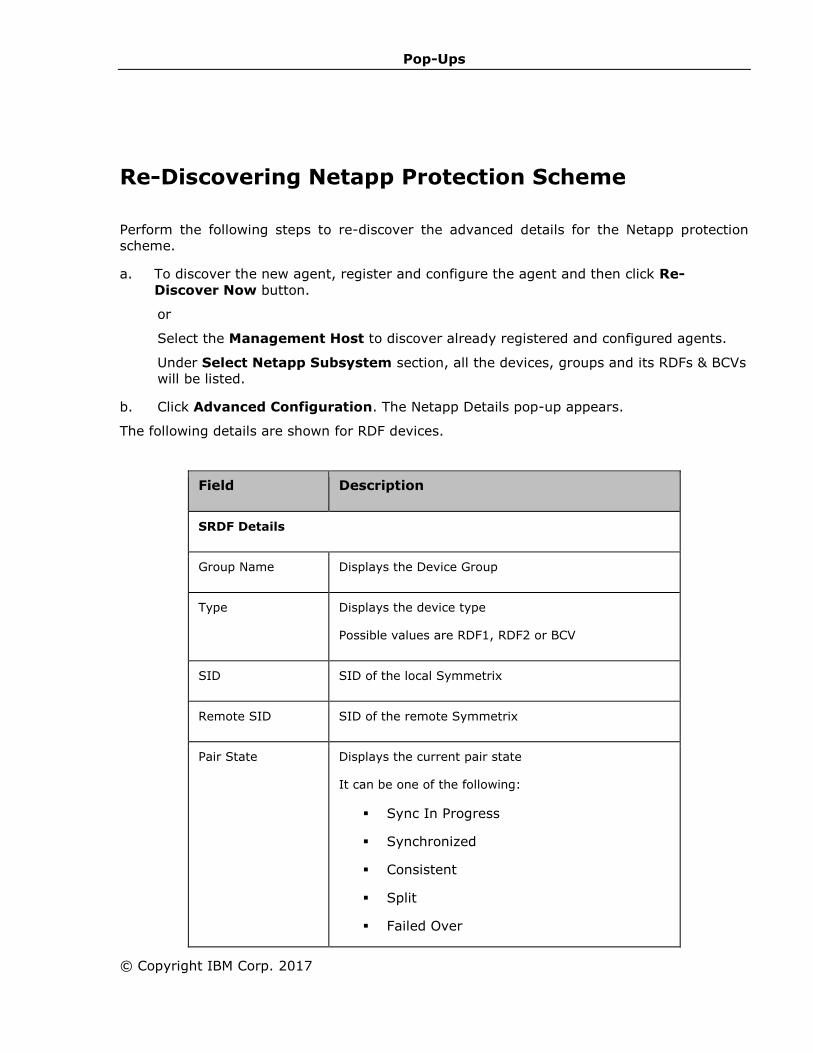
Pop-Ups
© Copyright IBM Corp. 2017
Re-Discovering Netapp Protection Scheme
Perform the following steps to re-discover the advanced details for the Netapp protection
scheme.
a. To discover the new agent, register and configure the agent and then click Re-
Discover Now button.
or
Select the Management Host to discover already registered and configured agents.
Under Select Netapp Subsystem section, all the devices, groups and its RDFs & BCVs
will be listed.
b. Click Advanced Configuration. The Netapp Details pop-up appears.
The following details are shown for RDF devices.
Field Description
SRDF Details
Group Name Displays the Device Group
Type Displays the device type
Possible values are RDF1, RDF2 or BCV
SID SID of the local Symmetrix
Remote SID SID of the remote Symmetrix
Pair State Displays the current pair state
It can be one of the following:
▪ Sync In Progress
▪ Synchronized
▪ Consistent
▪ Split
▪ Failed Over

IBM Resiliency Orchestration Administrator’s Guide
Field Description
▪ R1 Updated
▪ R1 Update In Progress
▪ Suspended
▪ Partitioned
▪ Mixed
▪ Invalid
▪ TransIdle
Replication Mode Displays the replication mode.
The possible values are Synchronous or
Asynchronous.
Device Domino Display whether domino is Enabled or Disabled
Applicable only if the replication mode is
Synchronous.
Consistency Display whether consistency is Enabled or Disabled
Applicable only if the replication mode is
Asynchronous
RDF Device Details: The following is shown for each RDF device
Logical Device
Name
Displays the logical name of the device
Symmetrix Device Displays the symmetrix device name/id
Remote device The remote Symmetrix device to which this logical
device is paired
Device Size Size in MB
Device State The device state
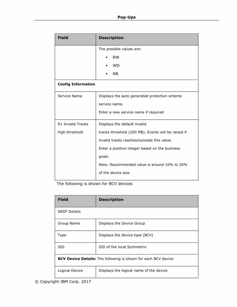
Pop-Ups
© Copyright IBM Corp. 2017
Field Description
The possible values are:
▪ RW
▪ WD
▪ NR
Config Information
Service Name Displays the auto generated protection scheme
service name.
Enter a new service name if required
R1 Invalid Tracks
high threshold
Displays the default invalid
tracks threshold (250 MB). Events will be raised if
invalid tracks reaches/exceeds this value.
Enter a positive integer based on the business
goals.
Note: Recommended value is around 10% to 20%
of the device size.
The following is shown for BCV devices
Field Description
SRDF Details
Group Name Displays the Device Group
Type Displays the device type (BCV)
SID SID of the local Symmetrix
BCV Device Details: The following is shown for each BCV device
Logical Device Displays the logical name of the device

IBM Resiliency Orchestration Administrator’s Guide
Field Description
Name
Symmetrix Device Displays the symmetrix device name/id
Attached to RDF
Logical Device
The RDF logical device to which this BCV device is
attached
Device Size Size in MB
Device State The device state
The possible values are:
▪ RW
▪ WD
▪ NR
Config Information
Service Name Displays the auto generated protection scheme
service name.
Enter a new service name if required
c. Click Save in the Device Group Information page.
d. Click Finish.
Note
1. Auto Discovery would return only those Device Group for which have atleast
one device. The Device Group that do not have any devices configured, cannot
be auto discovered.
2. The agent should be configured properly for auto discovery.

Pop-Ups
© Copyright IBM Corp. 2017
Setting System Options for Users
Super Administrator has the to set default settings for users.
Click IBM Resiliency Orchestration Server User Role Management to see the .
To establish settings for default users:
a. Click Admin on the navigation bar. The IBM Resiliency Orchestration Administration
page appears. Scroll down to the User Summary and click Go to Users. The IBM
Resiliency Orchestration Users page appears.
b. Click the Set System Options for Users link at the top right corner of the page. The
Set System Options for Users page appears.
Field Description
Preferences
Home Page Select the landing page for all users that is displayed after logging on to IBM Resiliency Orchestration.
Edit Options
User Details Select users who could be allowed to edit their own details.
Password
All User Passwords expire in Select the duration for the expiry of passwords.
a. Enter the numeral in the text box, and
b. Select the unit of time from the drop
down. The available options are: Never,
Days, Weeks, and Months.
Note
Select "Never" if you do not want the password to
expire.
Notify User on Password expiry
(Days before)
Enter the number of days before expiry you want to notify the user regarding expiration of password.
Professional Details
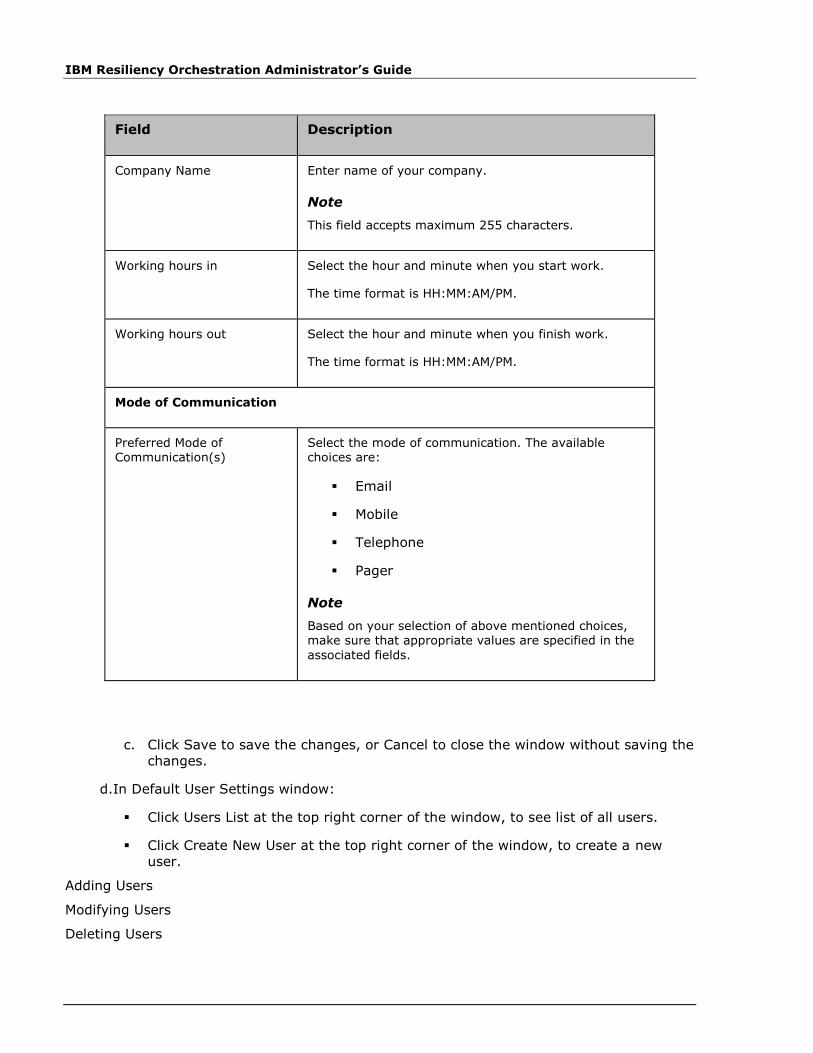
IBM Resiliency Orchestration Administrator’s Guide
Field Description
Company Name Enter name of your company.
Note
This field accepts maximum 255 characters.
Working hours in Select the hour and minute when you start work.
The time format is HH:MM:AM/PM.
Working hours out Select the hour and minute when you finish work.
The time format is HH:MM:AM/PM.
Mode of Communication
Preferred Mode of Communication(s)
Select the mode of communication. The available choices are:
▪ Mobile
▪ Telephone
▪ Pager
Note
Based on your selection of above mentioned choices, make sure that appropriate values are specified in the
associated fields.
c. Click Save to save the changes, or Cancel to close the window without saving the
changes.
d. In Default User Settings window:
▪ Click Users List at the top right corner of the window, to see list of all users.
▪ Click Create New User at the top right corner of the window, to create a new
user.
Adding Users
Modifying Users
Deleting Users
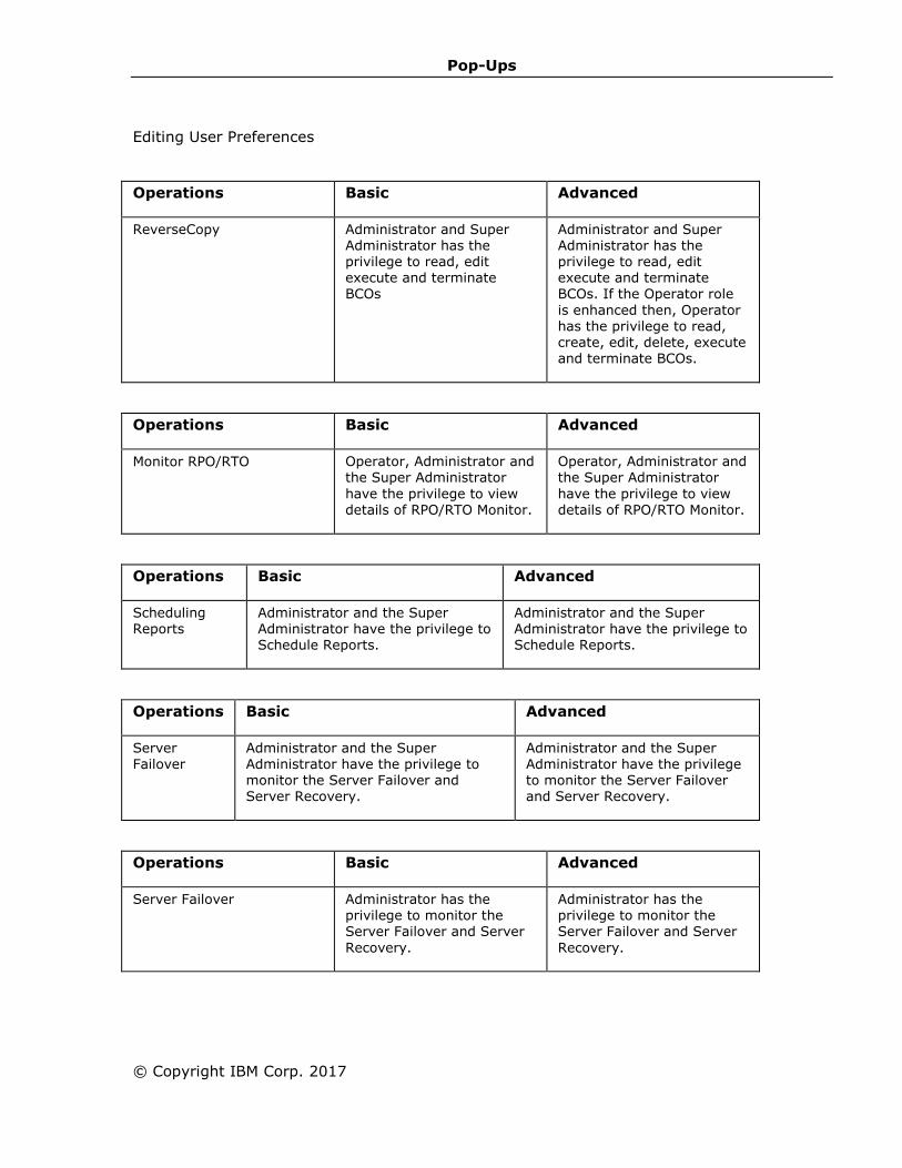
Pop-Ups
© Copyright IBM Corp. 2017
Editing User Preferences
Operations Basic Advanced
ReverseCopy Administrator and Super Administrator has the privilege to read, edit execute and terminate BCOs
Administrator and Super Administrator has the privilege to read, edit execute and terminate BCOs. If the Operator role
is enhanced then, Operator has the privilege to read, create, edit, delete, execute and terminate BCOs.
Operations Basic Advanced
Monitor RPO/RTO Operator, Administrator and the Super Administrator
have the privilege to view details of RPO/RTO Monitor.
Operator, Administrator and the Super Administrator
have the privilege to view details of RPO/RTO Monitor.
Operations Basic Advanced
Scheduling Reports
Administrator and the Super Administrator have the privilege to Schedule Reports.
Administrator and the Super Administrator have the privilege to Schedule Reports.
Operations Basic Advanced
Server Failover
Administrator and the Super Administrator have the privilege to monitor the Server Failover and Server Recovery.
Administrator and the Super Administrator have the privilege to monitor the Server Failover and Server Recovery.
Operations Basic Advanced
Server Failover Administrator has the privilege to monitor the Server Failover and Server
Recovery.
Administrator has the privilege to monitor the Server Failover and Server
Recovery.

IBM Resiliency Orchestration Administrator’s Guide
Operations Basic Advanced
Setting Debug Level Administrator and Super Administrator have the
privilege to set the debug levels of IBM Resiliency Orchestration logs
Administrator and Super Administrator have the
privilege to set the debug levels of IBM Resiliency Orchestration logs
Operations Basic Advanced
Setting Log File Size Super Administrator has the privilege to update/edit the
log file size.
Super Administrator has the privilege to update/edit the
log file size.
Operations Basic Advanced
Setting Log File Size Administrator and the Super Administrator have the privilege to edit/update Logs.
Administrator and the Super Administrator have the privilege to edit/update Logs.
Operations Basic Advanced
Setting System Options for Users
Super Administrator has the privilege to update/edit
the Users.
Super Administrator has the privilege to update/edit
the Users.
Operations Basic Advanced
Site Listing Operator, Administrator and Super Administrator have the privilege to read the details related to Sites.
Operator, Administrator and Super Administrator have the privilege to read the details related to Sites.
Operations Basic Advanced
Starting Agents Administrator and the Super Administrator have the privilege to read, update/edit and execute Agents.
Administrator and the Super Administrator have the privilege to read, update/edit and execute Agents.
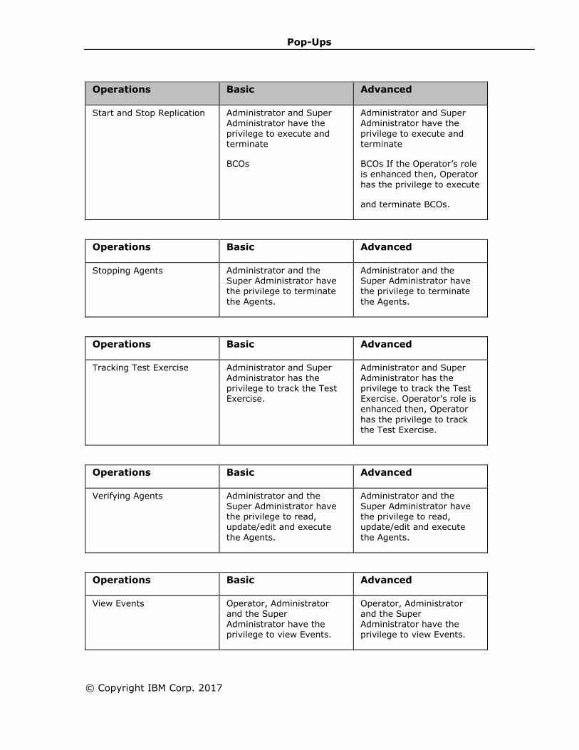
Pop-Ups
© Copyright IBM Corp. 2017
Operations Basic Advanced
Start and Stop Replication Administrator and Super Administrator have the
privilege to execute and terminate
BCOs
Administrator and Super Administrator have the
privilege to execute and terminate
BCOs If the Operator’s role is enhanced then, Operator
has the privilege to execute
and terminate BCOs.
Operations Basic Advanced
Stopping Agents Administrator and the Super Administrator have the privilege to terminate
the Agents.
Administrator and the Super Administrator have the privilege to terminate
the Agents.
Operations Basic Advanced
Tracking Test Exercise
Administrator and Super Administrator has the privilege to track the Test
Exercise.
Administrator and Super Administrator has the privilege to track the Test
Exercise. Operator's role is enhanced then, Operator
has the privilege to track the Test Exercise.
Operations Basic Advanced
Verifying Agents Administrator and the Super Administrator have the privilege to read, update/edit and execute
the Agents.
Administrator and the Super Administrator have the privilege to read, update/edit and execute
the Agents.
Operations Basic Advanced
View Events Operator, Administrator and the Super Administrator have the privilege to view Events.
Operator, Administrator and the Super Administrator have the privilege to view Events.
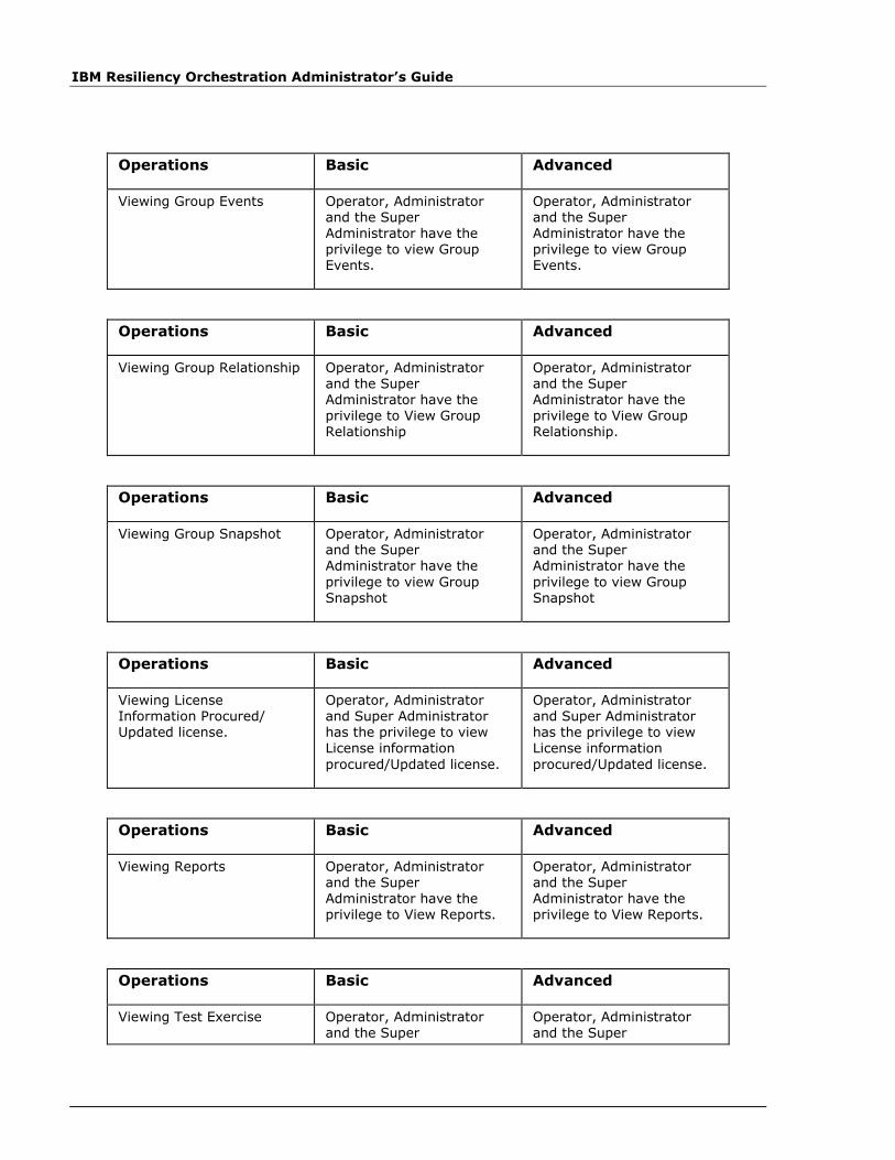
IBM Resiliency Orchestration Administrator’s Guide
Operations Basic Advanced
Viewing Group Events Operator, Administrator and the Super Administrator have the privilege to view Group Events.
Operator, Administrator and the Super Administrator have the privilege to view Group Events.
Operations Basic Advanced
Viewing Group Relationship Operator, Administrator and the Super Administrator have the privilege to View Group Relationship
Operator, Administrator and the Super Administrator have the privilege to View Group Relationship.
Operations Basic Advanced
Viewing Group Snapshot Operator, Administrator and the Super Administrator have the
privilege to view Group Snapshot
Operator, Administrator and the Super Administrator have the
privilege to view Group Snapshot
Operations Basic Advanced
Viewing License Information Procured/ Updated license.
Operator, Administrator and Super Administrator has the privilege to view License information
procured/Updated license.
Operator, Administrator and Super Administrator has the privilege to view License information
procured/Updated license.
Operations Basic Advanced
Viewing Reports Operator, Administrator and the Super Administrator have the privilege to View Reports.
Operator, Administrator and the Super Administrator have the privilege to View Reports.
Operations Basic Advanced
Viewing Test Exercise Operator, Administrator and the Super
Operator, Administrator and the Super
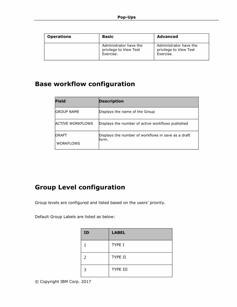
Pop-Ups
© Copyright IBM Corp. 2017
Operations Basic Advanced
Administrator have the privilege to View Test Exercise.
Administrator have the privilege to View Test Exercise.
Base workflow configuration
Field Description
GROUP NAME Displays the name of the Group
ACTIVE WORKFLOWS Displays the number of active workflows published
DRAFT
WORKFLOWS
Displays the number of workflows in save as a draft form.
Group Level configuration
Group levels are configured and listed based on the users’ priority.
Default Group Labels are listed as below:
ID LABEL
1 TYPE I
2 TYPE II
3 TYPE III

IBM Resiliency Orchestration Administrator’s Guide
ID LABEL
4 TYPE IV
1. Click Save, to save the lD and its group label.


