Page 1
VLSI Physical Design: From Graph Partitioning to Timing Closure Chapter 3: Chip Planning
© K
LMH
Lie
nig1
Modern Floorplanning Based on B*-Tree and Fast Simulated Annealing
Presented by: Jie Zou
University of Michigan
Fall 2011
Page 2
VLSI Physical Design: From Graph Partitioning to Timing Closure Chapter 3: Chip Planning
© K
LMH
Lie
nig2
Modern Floorplanning Based on B*-Tree and Fast Simulated Annealing
Introduction
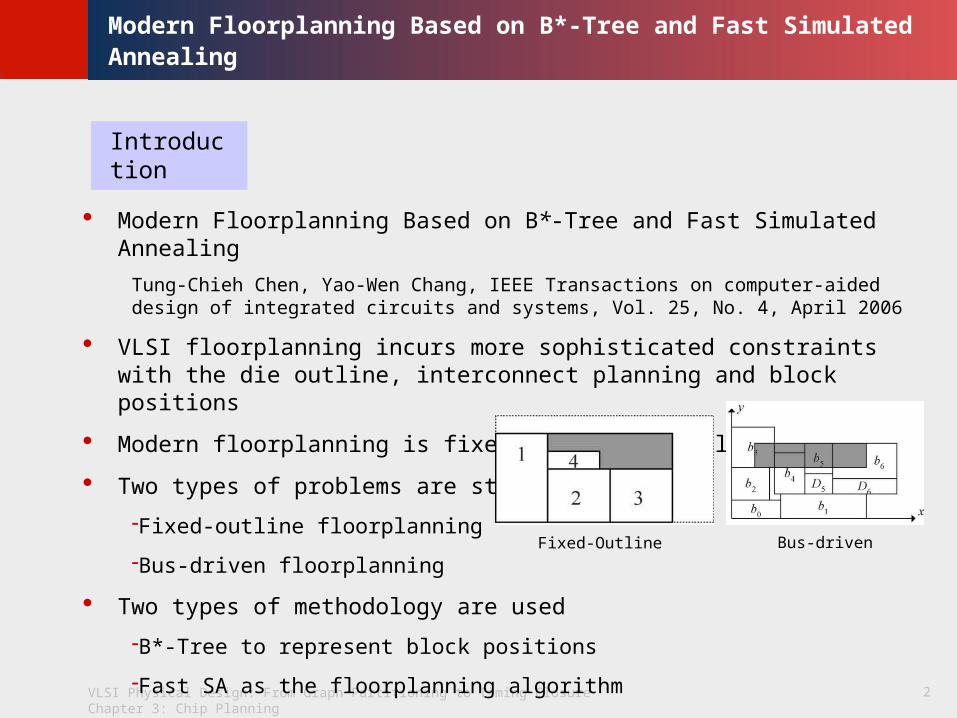
Modern Floorplanning Based on B*-Tree and Fast Simulated Annealing
Tung-Chieh Chen, Yao-Wen Chang, IEEE Transactions on computer-aided design of integrated circuits and systems, Vol. 25, No. 4, April 2006
VLSI floorplanning incurs more sophisticated constraints with the die outline, interconnect planning and block positions
Modern floorplanning is fixed-outline floorplanning
Two types of problems are studied
Fixed-outline floorplanning
Bus-driven floorplanning
Two types of methodology are used
B*-Tree to represent block positions
Fast SA as the floorplanning algorithm
Fixed-Outline Bus-driven
Page 3
VLSI Physical Design: From Graph Partitioning to Timing Closure Chapter 3: Chip Planning
© K
LMH
Lie
nig3
Modern Floorplanning Based on B*-Tree and Fast Simulated Annealing
B*-Tree Representation
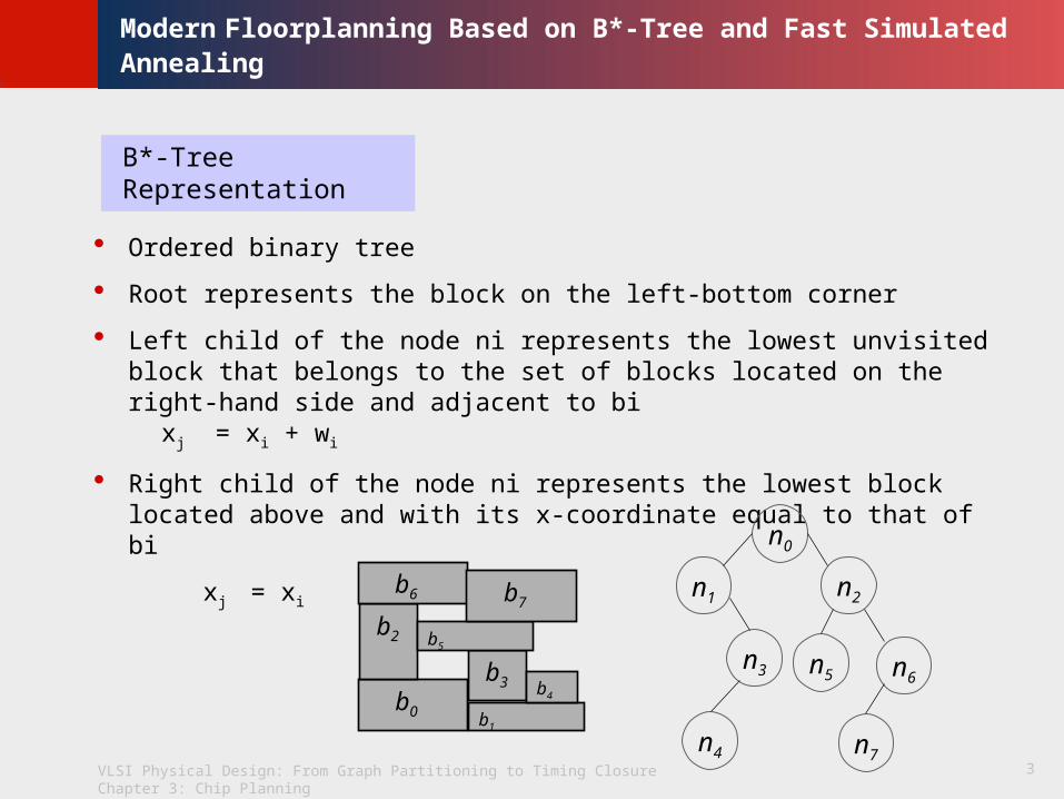
Ordered binary tree
Root represents the block on the left-bottom corner
Left child of the node ni represents the lowest unvisited block that belongs to the set of blocks located on the right-hand side and adjacent to bi
xj = xi + wi
Right child of the node ni represents the lowest block located above and with its x-coordinate equal to that of bi
xj = xi
b0 b1
b2
b3 b4
b5
b6 b7
n0
n1
n3
n4
n2
n5
n7
n6
Page 4
VLSI Physical Design: From Graph Partitioning to Timing Closure Chapter 3: Chip Planning
© K
LMH
Lie
nig4
Modern Floorplanning Based on B*-Tree and Fast Simulated Annealing
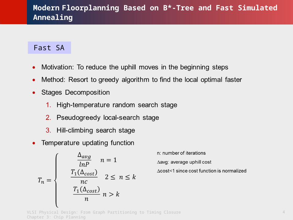
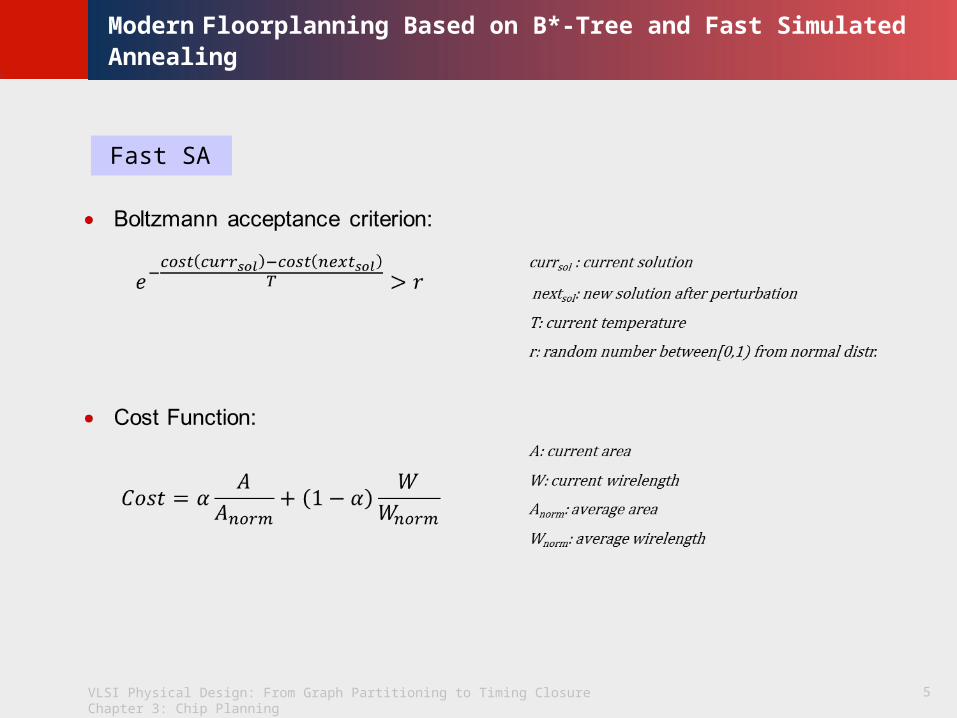
Fast SA
Page 5
VLSI Physical Design: From Graph Partitioning to Timing Closure Chapter 3: Chip Planning
© K
LMH
Lie
nig5
Modern Floorplanning Based on B*-Tree and Fast Simulated Annealing
Fast SA
Page 6
VLSI Physical Design: From Graph Partitioning to Timing Closure Chapter 3: Chip Planning
© K
LMH
Lie
nig6
Modern Floorplanning Based on B*-Tree and Fast Simulated Annealing
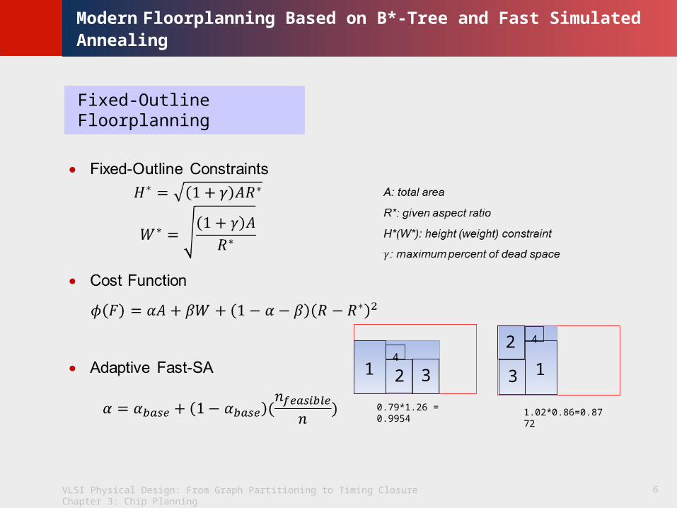
Fixed-Outline Floorplanning
14
2 3
0.79*1.26 = 0.9954
1
2
3
4
1.02*0.86=0.8772
Page 7
VLSI Physical Design: From Graph Partitioning to Timing Closure Chapter 3: Chip Planning
© K
LMH
Lie
nig7
Modern Floorplanning Based on B*-Tree and Fast Simulated Annealing
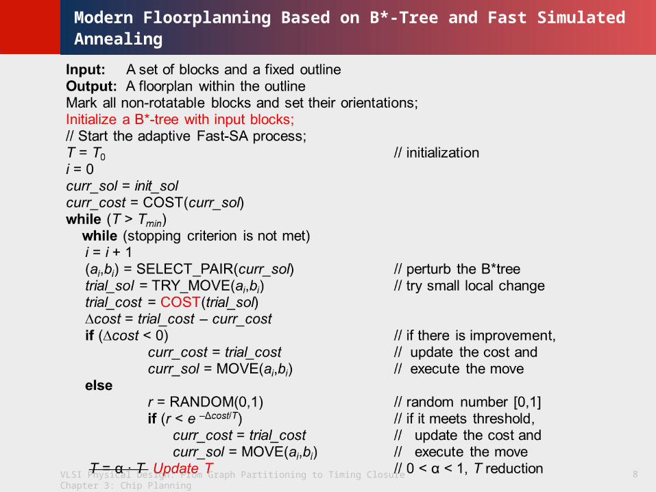
Input: A set of blocks and a fixed outlineOutput: A floorplan within the outlineMark all non-rotatable blocks and set their orientations;Initialize a B*-tree with input blocks;// Start the adaptive Fast-SA process;T = T0 // initializationdo
Perturb the B*Tree;Pack macro blocks;Evaluate the B*-tree cost;Decide if we should accept the new B*-tree;Modify the weights in the cost function;Update T;
until converged or cooling down;return the best solution;
Pseudocode
Page 8
VLSI Physical Design: From Graph Partitioning to Timing Closure Chapter 3: Chip Planning
© K
LMH
Lie
nig8
Modern Floorplanning Based on B*-Tree and Fast Simulated Annealing
Page 9
VLSI Physical Design: From Graph Partitioning to Timing Closure Chapter 3: Chip Planning
© K
LMH
Lie
nig9
Modern Floorplanning Based on B*-Tree and Fast Simulated Annealing
Bus-Driven Floorplanning (BDF)
Problem statements
n rectangular macro blocks B = {bi|i = 1, . . . , n} & m buses U = {ui|i = 1, . . . , m} each bus ui has a width ti and goes through a set of blocks Bi, Bi B ⊆ and |Bi| = ki
no overlap between any two blocks or between any two horizontal (vertical) buses
bus ui goes through all of its ki blocks
the chip area and the bus area are minimized
Characteristics of buses
assigned on the top two metal layers
connect multiple blocks
either vertically or horizontally oriented
alignment constraint
blocks don’t need to be adjacent when connected by buses
Page 10
VLSI Physical Design: From Graph Partitioning to Timing Closure Chapter 3: Chip Planning
© K
LMH
Lie
nig10
Modern Floorplanning Based on B*-Tree and Fast Simulated Annealing
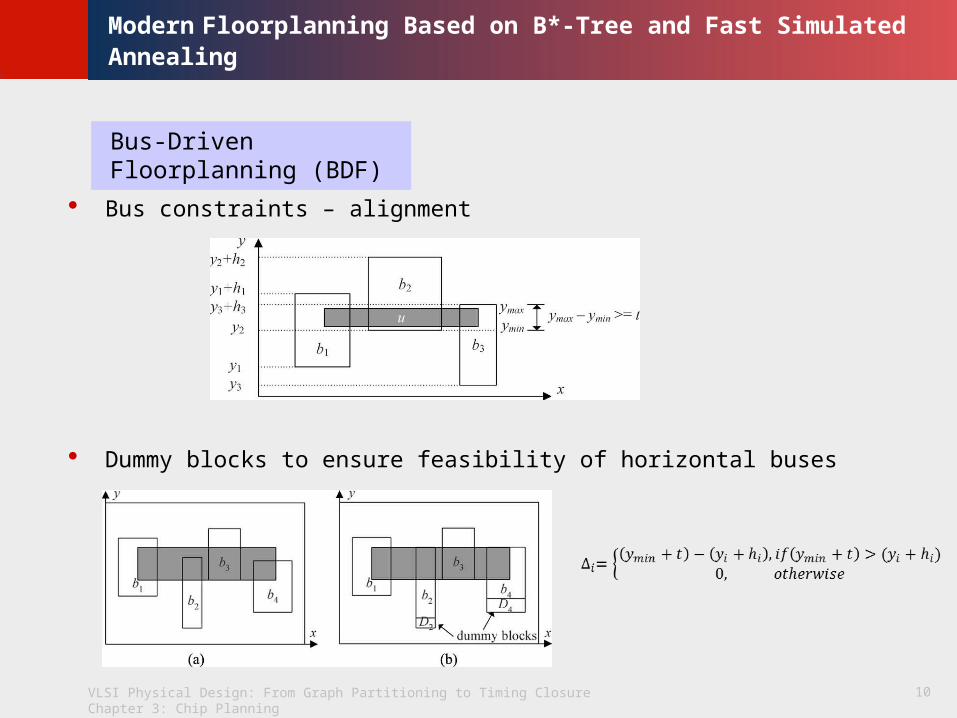
Bus-Driven Floorplanning (BDF)
Bus constraints – alignment
Dummy blocks to ensure feasibility of horizontal buses
Page 11
VLSI Physical Design: From Graph Partitioning to Timing Closure Chapter 3: Chip Planning
© K
LMH
Lie
nig11
Modern Floorplanning Based on B*-Tree and Fast Simulated Annealing
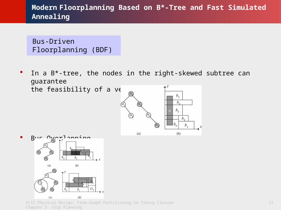
Bus-Driven Floorplanning (BDF)
In a B*-tree, the nodes in the right-skewed subtree can guarantee the feasibility of a vertical bus
Bus Overlapping
Page 12
VLSI Physical Design: From Graph Partitioning to Timing Closure Chapter 3: Chip Planning
© K
LMH
Lie
nig12
Modern Floorplanning Based on B*-Tree and Fast Simulated Annealing
Bus-Driven Floorplanning (BDF)
Fixed I/O ports define fixed orientation of buses connected to the ports
Twisted buses
Page 13
VLSI Physical Design: From Graph Partitioning to Timing Closure Chapter 3: Chip Planning
© K
LMH
Lie
nig13
Modern Floorplanning Based on B*-Tree and Fast Simulated Annealing
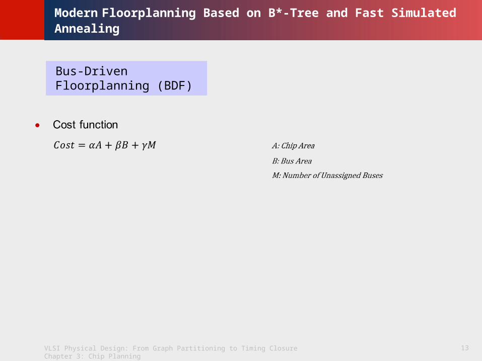
Bus-Driven Floorplanning (BDF)
Page 14
VLSI Physical Design: From Graph Partitioning to Timing Closure Chapter 3: Chip Planning
© K
LMH
Lie
nig14
Modern Floorplanning Based on B*-Tree and Fast Simulated Annealing
Input: A set of blocks and a set of bus constraintsOutput: A floorplan satisfying bus constraints with minimized chip area and total bus
area Initialize a B*-tree with input blocks;// Perform the Fast-SA process;T = T0 // initializationdo
Perturb the B*Tree;Pack macro blocks without dummy blocks;if there exists a “twisted-bus structure” in the B*-tree;
then restart the do-loop;Adjust the heights of the dummy blocks to fix horizontal bus constraints and fix bus-
overlapping;Pack macro blocks with dummy blocks;Decide bus locations;Evaluate the floorplan cost;Decide if we should accept the new B*-tree;Update T;
until converged or cooling down;return the best solution;
Pseudocode
Page 15
VLSI Physical Design: From Graph Partitioning to Timing Closure Chapter 3: Chip Planning
© K
LMH
Lie
nig15
Modern Floorplanning Based on B*-Tree and Fast Simulated Annealing
Application -- Parquet
Authors: Saurabh Adya, Hayward H. Chan, Igor Markov.
Latest version: PARQUET-4.5
Homepage: http://vlsicad.eecs.umich.edu/BK/parquet
Descriptions
free open-source software for fixed-outline floorplanning
based on Simulated Annealing
can also be applied to classical outline-free min-area block packing
internal floorplan representation alternates between sequence pairs and B*-Trees
Page 16
VLSI Physical Design: From Graph Partitioning to Timing Closure Chapter 3: Chip Planning
© K
LMH
Lie
nig16
Modern Floorplanning Based on B*-Tree and Fast Simulated Annealing
Q&A
Thank You !


![Floorplanning - National Taiwan Universitycc.ee.ntu.edu.tw/~ywchang/Courses/PD_Source/EDA_floorplanning.pdf · Sherwani 1999]. Basically, simulated annealing-based floorplanning relies](https://static.documents.pub/doc/80x56/5a79a4137f8b9a28678c4078/floorplanning-national-taiwan-ywchangcoursespdsourceedafloorplanningpdfsherwani.jpg)


