International Journal of Mechanical Engineering and Applications 2015; 3(5): 86-93
Published online August 17, 2015 (http://www.sciencepublishinggroup.com/j/ijmea)
doi: 10.11648/j.ijmea.20150305.12
ISSN: 2330-023X (Print); ISSN: 2330-0248 (Online)
Volume of Material Removal on Distortion in Machining Thin Wall Thin Floor Components
Garimella Sridhar, Ramesh Babu Poosa
Department of Mechanical Engineering, University College of Engineering, Osmania University, Hyderabad, India
Email address: [email protected] (G. Sridhar), [email protected] (R. B. Poosa)
To cite this article: Garimella Sridhar, Ramesh Babu Poosa. Volume of Material Removal on Distortion in Machining Thin Wall Thin Floor Components.
International Journal of Mechanical Engineering and Applications. Vol. 3, No. 5, 2015, pp. 86-93. doi: 10.11648/j.ijmea.20150305.12
Abstract: Thin wall thin floor monolithic components produced from prismatic blocks are machined on CNC machines by
removing material up to 95 %. Components distort because of stresses induced due to severe heat generated and plastic
deformation during cutting. Distortion of the components after machining aluminium alloys is major problem faced in aerospace
and automobile industries. The volume of the material removed has direct bearing on machining time, which may lead to
distortion. The objective of this study is to determine the effect of volume of material removal on the distortion of aluminium
2014 T651 alloy machined from prismatic block. Machining experiments were carried out with 5 different blank sizes to produce
a representative component with same machining parameters. Distortion is measured on the face opposite to the machined
surface and maximum deviations were used for comparisons between distortion and volume of material removal.
Keywords: Volume of Material Removal, Distortion, Blank Size
1. Introduction
With high strength to weight ratios and reduced assembly
costs, sheet metal and multiple part assemblies are replaced by
single piece monolith high strength aluminium alloy designs.
With huge amount of material to be removed from large areas
machining of these on CNC machines has become quite
common and inevitable. Previous studies of authors on
challenges in machining these components show that one of
the biggest problems is distortion [1]. In a general
manufacturing scenario all the monolithic thin structured
components are produced on CNC machining centres from
Pre-machined Prismatic blanks of planned sizes and thickness.
The blanks are generally cut from rolled sheets of pre-planned
thickness and are sized to the required dimensions on a
conventional milling machine before machining them on CNC
machining centres. As the volume of material removed is up to
95 %, the components distort due to stresses induced into the
component because of temperature gradient and differential
plastic deformations during cutting [2-4]. The magnitude,
distribution and type of residual stresses induced during
cutting is the main cause of distortion which is a function of
machining parameters, tool geometry, cutting strategy and
clamping methodology for a component of given material [5].
In recent years, lot of research was done to control the
distortion of parts during machining. Hengbo Cui, Jong-Yun
Jung and Dug-Hee Moon applied Taguchi method to know
affect of deformation caused by heat during cutting of AL
7050/T7451 and found that cutting speed is the most
influencing factor which causes deformation due to heat and
the change of feed range has an insignificant effect on heat
deformation [6]. Dong, Hui-yue, and Ying-lin KE carried out
comparison of simulation and machining experiments on wing
spar made of aluminium 7075 alloy using single tool- tooth
milling simulation using Deform 3D, importing the force and
temperature data into Abacus and simulating the machining
experiments further by restart calculation and local
re-meshing. The experiments showed good agreement with
the simulation results and demonstrated that this method can
be used to select optimal tool-path and machining sequences
for minimizing distortion [7]. J-F. Lalonde, M.A. Gharghouri
and J-F. Chatelain in their experiments and measurement of
residual stresses by neutron diffraction method on controlled
pre-processed blanks and standard blanks found that, the
standard aluminium blanks distorted more because of
asymmetrical bulk residual stresses in the blank because of
previous operations before machining [8]. Younger, Mandy S.,
and Kenneth H. Eckelmeyer in their study concluded that
distortion increases with increasing residual stress magnitude,
increasing machining depth, and increasing machining
asymmetry [9]. Denkena, B., and L. de León conducted
International Journal of Mechanical Engineering and Applications 2015; 3(5): 86-93 87
machining experiments and showed in the results that
machining operation and cutting edge geometry has a definite
influence in the residual depth profile and residual stress
distribution which effect distortion [10]. Marusich T.D., DA.
Stephenson, S. Usui, and S. Lankalapalli proposed a
methodology for distortion in thin-walled components due to
both bulk and machining induced residual stresses which will
aid in selecting parameters which can minimize distortion [3].
O. Belgasim and M. H. El-Axir in their study on aluminium
magnesium alloy using response surface method, conducted
experiments and concluded that residual stresses are sensitive
to tool nose radius and feed rate. Cutting speed and depth of
cut are significant parameters affecting maximum residual
stresses which in turn affects distortion [11]. Similar results
were achieved by author in experiments conducted using
taguchi method to know the effect of distortion in machining
aluminium alloy AA2014 T651. Depth of cut and width of cut
were found to be significant contributors in machining
distortion [12]. Keleshian, N, et al., in their work conducted
machining experiments on aluminium alloy 7249 and
observed that solution treatment temperature, quenching
media, and various machining sequences affect distortion [13].
Chatelain, Jean-François, Jean-François Lalonde, and Antoine
S. Tahan conducted experiments on a thin representative part
to compare distortions with and without existing residual
stresses in work pieces and concluded that initial residual
stresses embedded within raw material has an effect on the
final part deformation [5]. Songtao Wang, Zheng Minli, Fan
Yihang, and Li Zhe conducted machining experiments on
aluminium alloy 7475-T7351 and concluded that machining
deformation of thin-walled components can be effectively
controlled with the parameter combination of big radial
cutting depth and small axial cutting depth in the condition of
high spindle speed [14]. Huang, Xiaoming, et al., conducted
high speed milling experiments on aluminium alloy
7050-T7541, measured residual stresses on the surface &
subsurface of the work piece and showed that decrease of the
cutting speed with increase of the feed rate lead to increase of
compressive residual stresses [15]. Huang, Xiaoming, Jie Sun,
and Jianfeng Li studied the effects of bulk residual stresses &
machining induced residual stresses and observed that
machining induced residual stresses is the primary cause of
the distortion and has greater effect when the thickness is
below 1.25 mm, also location of the part in the raw material
has some effect on distortion [16].
Although, much research was done on distortion during
machining of thin structured components, the impact of
volume of material removal on distortion was not studied.
Volume of material removed is total amount of material
machined out from the prismatic blank to form component. As
thickness of the blank increases the volume of the material to
be removed and time of machining increases. This may lead to
increase in influence of magnitude and distribution of residual
stresses and distortion of the component after machining and
removing from the fixture. So, in order to understand the
effect of volume of material removal on distortion, machining
experiments were carried on representative thin wall thin floor
part from prismatic blocks of different thicknesses on CNC
machining centre using aluminium alloy 2014 T651 under
same machining conditions.
2. Experimental Setup and Procedure
In this study milling experiments were carried out on
Vertical CNC machining centre on a representative thin wall
thin floor part to know the effect of volume of material
removal on distortion of the component.
2.1. Workpiece
Aluminium alloy 2014 T651 is used as work piece material.
The mechanical properties of the material are shown in Table
1 and chemical properties of the material are shown in Table 2.
The alloy is copper based aluminium alloy which is solution
treated, artificially age hardened and stress relieved by
stretching. This alloy is commonly used for airframes and
mechanical packages for avionics. The blank sizes of length
105 mm and width 40 mm with different thicknesses i.e., 12
mm, 14 mm, 16 mm, 18 mm, and 20 mm are used for the
experiment. The representative thin wall thin floor component
for experimental work is shown in Figure 1.
Table 1. Mechanical Properties.
Property Value
Yield strength 380 Mpa
Tensile strength 405 Mpa
Hardness Rockwell B 82
Density 2.80 g/cc
Poisson’s Ratio 0.2
Table 2. Chemical composition.
Property Value
Copper 3.8 to 4.8
Magnesium 0.2 to 0.8
Silicon 0.6 to 0.9
Iron 0.7 max
Manganese 0.2 to 1.2
Aluminium Reminder
Figure 1. Experimental Workpiece.
88 Garimella Sridhar and Ramesh Babu Poosa: Volume of Material Removal on Distortion in
Machining Thin Wall Thin Floor Components
Figure 2. Solid Carbide slot Drill.
Figure 3. Hardinge Bridgeport VMC 600 P3.
Table 3. Specification of Machine.
Maximum RPM 8000 RPM
No. of Axes 3-Axes
X Axis Travel 600mm
Y Axis Travel 510mm
Z Axis Travel 510mm
Rapid Traverse 30 m/min
Feed 12 m/min
Power 13kW
Tool Station 20 Tools
Maximum Load 700kg
2.2. Tool
All the machining experiments were carried out using low
helix two flute solid carbide Slot Drill Ø10 mm. Figure 2
shows the picture of the tool. New cutter is used for each
machining experiment to eliminate the affect of tool wear. The
machining experiments were carried out on Hardinge
Bridgeport VMC 600 P3 3-axis Vertical Machining Centre as
shown in Figure 3. Table 3 shows the specifications of the
machine tool. All the experiments were carried by holding the
component from the bottom using specially made vacuum
fixture as shown in Figure 4.
Figure 4. Vacuum Fixture along with work piece.
2.3. Measurement
Before Experiments, 18 points are marked on the opposite
side of the face to be machined on all the work pieces as
shown in Figure 5. The distortion is measured by taking the
difference of Deviation before and after machining on the 18
marked places and maximum deviation is taken for
comparison. Distortion measurements were carried using
Metris LK Integra using CAMIO 4.4 software with
Specifications: Size 800 mm X 700 mm X 600 mm, Accuracy
1.9+L/450 µ, Repeatability 2.2 µ and probe error 3.6 µ as
shown in Figure 6. Twist in the components was also
measured using Feeler gauges. The measurement of twist is
shown in Figure 7. Comparisons between the experiments
were done by taking the maximum deviation of the work piece
after machining.
Figure 5. Marking of measuring point.
International Journal of Mechanical Engineering and Applications 2015; 3(5): 86-93 89
Figure 6. CMM with work piece.
Figure 7. Picture showing measurement of twist.
Table 4. Machining Parameters.
Title Value
Feed 0.1 mm/Tooth
Speed 120 m/min
Depth of cut 1mm
Width of cut 7mm
Coolant Dry machining
2.4. Methodology
Aluminium rolled plates of 12 mm, 14 mm, 16 mm, 18
mm and 20 mm thick were cut into sizes 110 mm X 45 mm.
The blanks were then sized to 105 mm X 40 mm on a vertical
milling machine. After sizing, all the blanked were stress
relieved, there by assuming very little or almost zero bulk
residual stresses before machining them on CNC machining
centre. The blanks after stress relief were machined by
holding the part on specially made vacuum fixture from the
bottom using low helix two flute solid carbide Slot Drill ø 10
mm. The machining conditions used for milling all the
blanks is shown in Table 4. All the machining experiments
were carried out under same machining conditions.
Each blank during machining is taken out of fixture for
every depth of cut which is 1mm and measurements were
taken for distortion and twist. The cutting strategy adopted
for the experiments was pocket Inside out as shown in Figure
8. Three sample work pieces were machined for each
thickness of blank.
Figure 8. Tool Path Strategy pocket inside out.
3. Experimental Results and Discussions
Distortion and Twist measurements were taken for every
1mm depth of machining for all the blanks. The distortion
and twist measurements for blank thickness of 20 mm, 18
mm, 16 mm, 14 mm, and 12 mm for every 1 mm depth of cut
are taken for 3 samples each and maximum distortion and
twist were recorded for comparison. Table 5 shows the
values of distortion and twist at every 1 mm depth of cut for
blank thickness 20mm. The maximum distortion and twist
values for the blanks of all thicknesses at every 1 mm depth
of machining are shown in Table 6. Comparative values of
distortion & twist with respect to volume of material
removed is shown in Table 7.
It can be observed from Table 6 that distortion and twist
was observed for all the components machined. Significant
distortion and twist was noticed only after the thickness of
the components in the floor (bottom) is less than 3 mm after
machining, for all the components. Figure 9 shows distortion
and twist with respect to volume of material removal. It can
be seen that, there no significant increase in distortion and
twist with increase in volume of material removal.
The results clearly show that distortion of the components
does not depend on the amount of material removed. As the
amount of material machined increased from 44880 mm3 to
700800 mm3 there was no significant increase in distortion
from initial distortion of 0.45 mm indicating that the
distortion of the components may depend on machining
parameters and tool parameters. The slight increase in twist
for 20 mm thick blanks may be attributed to the variation of
bulk residual stresses distribution existing in the blank prior
to machining. It can be observed from Figure 10 and Figure 11
that the distortion and twist of the components was significant
at thickness less than 3 mm for all the blanks indicating the
effect of machining induced surface stresses causing distortion
as reported in previous research [5, 15, 16].
90 Garimella Sridhar and Ramesh Babu Poosa: Volume of Material Removal on Distortion in
Machining Thin Wall Thin Floor Components
Figure 9. Comparison of distortion and twist.
Table 5. Distortion and Twist values for 20 mm Blank.
Blank
(mm)
Distortion / Twist at
Thickness
Sample 1 Sample2 Sample3 Maximum
Dist. (mm) Twist (mm) Dist. (mm) Twist (mm) Dist. (mm) Twist (mm) Dist. (mm) Twist (mm)
20
20 0 0 0 0 0 0 0 0
19 0 0 0 0 0 0 0 0
18 0 0 0 0 0 0 0 0
17 0 0 0 0 0 0 0 0
16 0 0 0 0 0 0 0 0
15S 0 0 0 0 0 0 0 0
14 0 0 0 0 0 0 0 0
13 0 0 0 0 0 0 0 0
12 0 0 0 0 0 0 0 0
11 0 0 0 0 0 0 0 0
10 0 0 0 0 0 0 0 0
9 0 0 0 0 0 0 0 0
8 0 0 0 0 0 0 0 0
7 0 0 0 0 0 0 0 0
6 0 0 0 0 0 0 0 0
5 0 0 0 0 0 0 0 0
4 0.05 0.1 0.08 0.1 0.08 0.12 0.08 0.12
3 0.21 0.4 0.22 0.45 0.2 0.45 0.22 0.45
2 0.35 0.7 0.34 0.75 0.35 0.75 0.35 0.75
1 0.55 1.1 0.49 1.05 0.52 1.05 0.55 1.1
International Journal of Mechanical Engineering and Applications 2015; 3(5): 86-93 91
Table 6. Maximum values of Distortion and Twist (mm) at various thicknesses.
Blank
(mm)
Thick-ness
(mm) 20 19 18 17 16 15 14 13 12 11 10 9 8 7 6 5 4 3 2 1
20 DIST. 0 0 0 0 0 0 0 0 0 0 0 0 0 0 0 0 0.08 0.22 0.35 0.55
TWIST 0 0 0 0 0 0 0 0 0 0 0 0 0 0 0 0 0.12 0.45 0.75 1.1
18 DIST. - - 0 0 0 0 0 0 0 0 0 0 0 0 0 0 0 0.05 0.33 0.45
TWIST - - 0 0 0 0 0 0 0 0 0 0 0 0 0 0 0 0.25 0.55 1
16 DIST. - - - - 0 0 0 0 0 0 0 0 0 0 0 0 0 0.05 0.22 0.45
TWIST - - - - 0 0 0 0 0 0 0 0 0 0 0 0 0 0.25 0.6 0.9
14 DIST. - - - - - - 0 0 0 0 0 0 0 0 0 0 0 0 0.25 0.45
TWIST - - - - - - 0 0 0 0 0 0 0 0 0 0 0 0.15 0.6 0.9
12 DIST. - - - - - - - - 0 0 0 0 0 0 0 0 0 0.15 0.22 0.45
TWIST - - - - - - - - 0 0 0 0 0 0 0 0 0 0.15 0.44 0.85
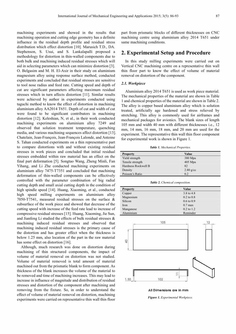
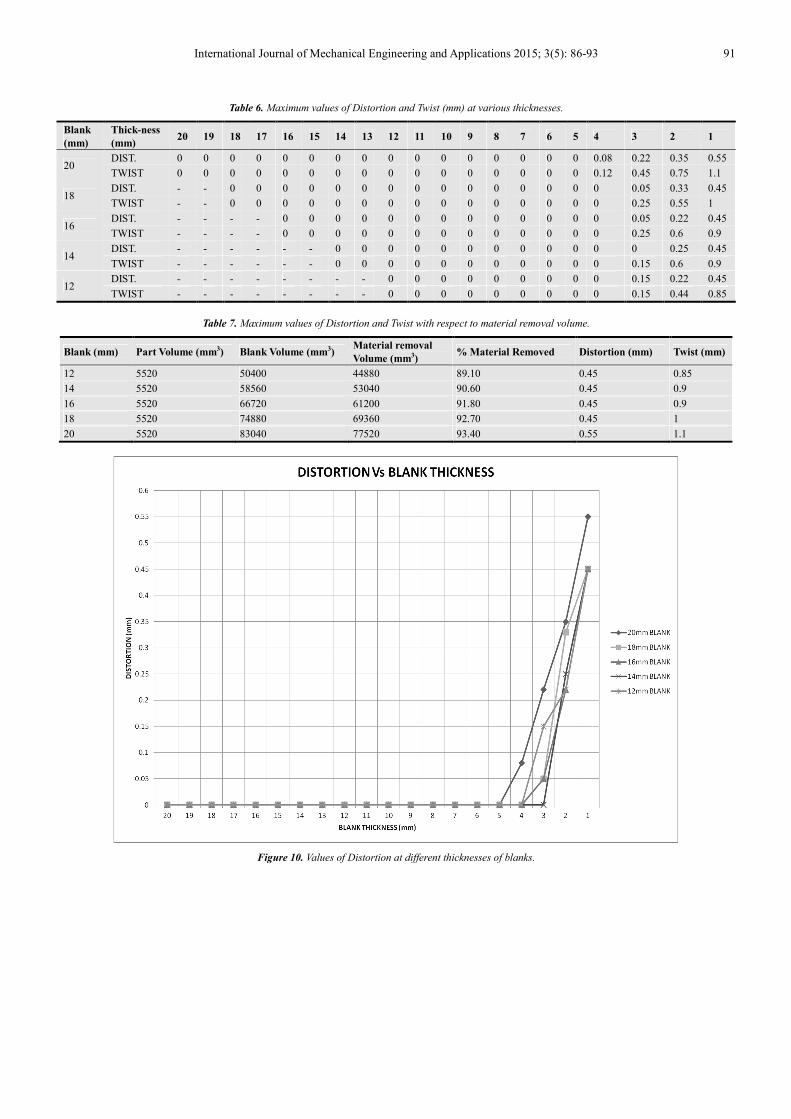
Table 7. Maximum values of Distortion and Twist with respect to material removal volume.
Blank (mm) Part Volume (mm3) Blank Volume (mm3) Material removal
Volume (mm3) % Material Removed Distortion (mm) Twist (mm)
12 5520 50400 44880 89.10 0.45 0.85
14 5520 58560 53040 90.60 0.45 0.9
16 5520 66720 61200 91.80 0.45 0.9
18 5520 74880 69360 92.70 0.45 1
20 5520 83040 77520 93.40 0.55 1.1
Figure 10. Values of Distortion at different thicknesses of blanks.
92 Garimella Sridhar and Ramesh Babu Poosa: Volume of Material Removal on Distortion in
Machining Thin Wall Thin Floor Components
Figure 11. Values of Twist at different thicknesses of blanks.
4. Conclusions
A comparison of distortion and twist vis-a-vis material
removal volume was done. Machining experiments were
carried with constant machining process parameters on stress
relieved aluminium alloy 2014 T651 with different thickness
of blanks. It was found that the amount of material removal
has no significant affect on distortion. Distortion may be due
to process parameters. Further, it was observed that the
distortion was significant only below 3mm thickness because
of surface induced stresses due to machining. Further study
should be focused on the effect of machining and tool
parameters on the distortion of the parts machined.
Acknowledgements
The authors are thankful to the Head of Department,
Osmania University for his constant encouragement and
Support for conducting experiments. The authors are also
thankful to the reviewers for their valuable inputs in
improving quality of the manuscript.
References
[1] Sridhar, Garimella, and P. Ramesh Babu. "Understanding the challenges in machining thin walled thin floored Avionics components, " International Journal of Applied Science and Engineering Research 2.1: 93-100, 2013.
[2] Stephenson, D. A., Agapiou, J. S., Metal Cutting Theory and Practice, Second Edition, CRC, Boca Raton, FL, 568-9, 2006.
[3] Marusich T. D., D. A. Stephenson, S. Usui, and S. Lankalapalli, "Modeling Capabilities for Part Distortion Management for Machined Components." Third Wave Systems (2009).
[4] Totten, George E., and D. Scott MacKenzie, eds. Handbook of Aluminum: Vol. 1: Physical Metallurgy and Processes. Vol. 1. CRC Press, 2003.
[5] Chatelain, Jean-François, Jean-François Lalonde, and Antoine S. Tahan, "Effect of Residual Stresses Embedded within Workpieces on the Distortion of Parts after Machining," International Journal of Mechanics 6: 43-5, 2012.
[6] Cui, Hengbo, Jong-Yun Jung, and Dug-Hee Moon, "The Selection of Machining Parameters to Minimize Deformation caused by Heat," Proceedings of the Fall Conference of Society of Korea Industrial and Systems Engineering, Korea. 2005.
[7] DONG, Hui-yue, and Ying-lin KE, "Study on machining deformation of aircraft monolithic component by FEM and experiment," Chinese Journal of Aeronautics 19.3: 247-254, 2006.
[8] Lalonde, J. F., M. A. Gharghouri, and J. F. Chatelain, "Effect of Residual Stresses on the Distortion of Components after Machining.", NRC-CNBC Annual Report 2007.
[9] Younger, Mandy S., and Kenneth H. Eckelmeyer. "Overcoming residual stresses and machining distortion in the production of aluminium alloy satellite boxes," Sandia Report SAND2007-6811, Sandia National Laboratories, 2007.
[10] Denkena, B., and L. de León, "Machining induced residual stress in wrought aluminium parts, " Proceedings of 2nd International Conference on Distortion Engineering. 2008.
[11] Belgasim, O., and M. H. El-Axir, "Modeling of residual stresses induced in machining aluminum magnesium alloy (Al–3Mg)," Proceedings of the world congress on engineering, Vol. 2. 2010.
International Journal of Mechanical Engineering and Applications 2015; 3(5): 86-93 93
[12] Garimella Sridhar and P. Ramesh Babu, "Cutting Parameter Optimization for Minimizing Machining Distortion of Thin Wall Thin Floor Avionic Components using Taguchi Technique", International Journal of Mechanical Engineering & Technology (IJMET).Volume:4,Issue:4,Pages:71-78, 2013.
[13] Keleshian, N., et al., "On the distortion and warpage of 7249 aluminum alloy after quenching and machining," Journal of materials engineering and performance 20.7: 1230-1234, 2011.
[14] Songtao Wang, Zheng Minli, Fan Yihang, and Li Zhe, "Cutting Parameters Optimization in Machining Thin-Walled Characteristics of Aircraft Engine Architecture based on Machining Deformation," Advances in Information Sciences & Service Sciences 4.10, 2012.
[15] Huang, Xiaoming, et al., "An Experimental Investigation of Residual Stresses in High-Speed End Milling 7050-T7451 Aluminum Alloy," Advances in Mechanical Engineering, 2013.
[16] Huang, Xiaoming, Jie Sun, and Jianfeng Li, "Effect of Initial Residual Stress and Machining-Induced Residual Stress on the Deformation of Aluminium Alloy Plate," Strojniški vestnik-Journal of Mechanical Engineering 61.2: 131-137, 2015.
[17] Ma, K., R. Goetz, and S. K. Srivatsa. "Modeling of residual stress and machining distortion in aerospace components." ASM Handbook 22, 2010.