42
Volume X: Socket Fusion Polypropylene System Industrial Technical Manual Series IPEX SOCKET FUSION POLYPROPYLENE SYSTEM (Pigmented socket fusion polypropylene) SECOND EDITION
| Date post: | 21-Aug-2018 |
| Category: |
Documents |
| Upload: | duongtuong |
| View: | 227 times |
| Download: | 0 times |

Volume X:Socket FusionPolypropyleneSystem
Industrial TechnicalManual Series
IPEX SOCKET FUSIONPOLYPROPYLENE SYSTEM
(Pigmented socket fusion polypropylene)
S E C O N D E D I T I O N

IPEX Socket Fusion Polypropylene System
Industrial Technical Manual Series Vol. X. 2nd Edition.
© 2003 by IPEX.

2
INTRODUCTION
INTR
ODU
CTIO
N T
O SF
POL
YPRO
This manual provides the most up-to-date and comprehensive information about IPEX Socket Fusion Polypropylene System(SF Polypro). All aspects of SF Polypro are covered from basic raw material properties to installation procedures of the finished product. Written with the engineer, contractor and distributor in mind, it is based on laboratory test results combinedwith IPEX’s years of field experience.
At IPEX, we have been manufacturing nonmetallic pipe and fittings since 1951. We formulate most of our own compoundsand maintain strict quality controls during production. Our products are then made available to distribution thanks to a network of regional stocking locations throughout North America. We offer a wide variety of systems including complete linesof piping, fittings, valves and custom-fabricated items.
More importantly, our commitment to customers extends beyond the sale. As a leader in the plastic piping industry, IPEX continually develops new products, modernizes manufacturing facilities, and acquires innovative process technology. In addition, our staff takes pride in their work, making available to our customers their extensive industry knowledge and fieldexperience with thermoplastic materials. For further information on more specific details about any IPEX product, contact ourcustomer service department.
Contents
Introduction to SF Polypro System . . . . . . . . . . . . . . . . . . . . . . . . . . . . . . . . . . . . . . . . . . . . . . . . . 3
Material Properties . . . . . . . . . . . . . . . . . . . . . . . . . . . . . . . . . . . . . . . . . . . . . . . . . . . . . . . . . . . . 5
Design Data . . . . . . . . . . . . . . . . . . . . . . . . . . . . . . . . . . . . . . . . . . . . . . . . . . . . . . . . . . . . . . . . 7
System Specifications . . . . . . . . . . . . . . . . . . . . . . . . . . . . . . . . . . . . . . . . . . . . . . . . . . . . . . . . . . . . . . . . . . . . . . . 23
Valve Specifications . . . . . . . . . . . . . . . . . . . . . . . . . . . . . . . . . . . . . . . . . . . . . . . . . . . . . . . . . . 24
Handling and Installation . . . . . . . . . . . . . . . . . . . . . . . . . . . . . . . . . . . . . . . . . . . . . . . . . . . . . . 31

3
INTRODUCTION TO SOCKET FUSION POLYPROPYLENE SYSTEM
INTRODU
CTION TO
SF POLYPRO
IPEX SF Polypropylene System is a complete system thatoffers:• A superior joint compared to solvent cement,
non-interference fit, butt or IR system welding.
• Copolymer pipe and homopolymer fittings and valves.
• Specialized hand-held and bench fusion equipment.
• Pipe, valves and fittings all designed and backed by one company—IPEX
IPEX provides efficient and qualified pre-and-post salesassistance, aimed at checking and encouraging the correctand optimum use of materials.
Exceptional Chemical Resistance
IPEX SF Polypro offers pipe, valves and fittings with outstandingresistance to a wide range of chemicals.
However, chemical resistance is a function of concentration,pressure and temperature. For specific applications, see theIPEX Chemical Resistance Guide.
Lower Installation Costs
In addition to a lower material cost, polypropylene pipe cansignificantly reduce labor and transportation costs on a typicalinstallation. The reason? Plastics are easily handled, stored,cut and joined. And, heavy equipment used to install metallicand other piping systems are not required, thereby reducingproject costs.
Extended Life
IPEX’s SF Polypro System is fundamentally ageless and impervious to normal weather conditions. Polypropylene piping systems in uninterrupted service and in a variety ofdemanding industrial applications have operated successfullyfor over 40 years. During maintenance or revisions, examinations of the original plastic materials showed excellent physical and hydraulic characteristics.
Once properly selected for the application and correctlyinstalled, IPEX SF Polypro provides years of maintenance-freeservice. Our materials will not rust, pit, scale or corrode oneither interior or exterior surfaces. Unlike other types of piping, polypropylene systems are not adversely affected byaggressive soil or atmospheric conditions.
Corrosion Resistance
Our polypropylene materials are immune to damage from naturally corrosive soil conditions as well as electrochemicaland galvanic corrosion. This is particularly advantageous inunderground installations where galvanic reaction often causes damage to metal piping products. Our polypropylene’snoncorroding properties ensure improved flow, lower maintenance costs and longer performance life.
Improved Flow
IPEX SF PP piping has a substantially lower Roughness Factorthan metal and other materials, and since thermoplastics donot rust, pit, scale or corrode, the interior walls remain smoothin virtually any service. This high carrying capacity may resultin the use of smaller diameter piping and or pumps.
IPEX’s Socket Fusion Polypropylene System is a complete PVF system utilized in some of the most demanding chemicalprocesses, where broad chemical resistance, high temperature performances and absolutely fool-proof joints are required.
Made from one of the most versatile thermoplastic materials, IPEX Socket Fusion Polypropylene System (SF Polypro) offersmetric pipe, valves and fittings that can be jointed in minutes to create superior connections. It is chemically andelectrochemically inert, non-conductive and resists galvanic corrosion making it an ideal system for the most demandingchemical process. The Socket Fusion system works in a broad range of applications and industries including the platingindustry, steel cable manufacturing, circuit board manufacturing, battery manufacturing and the food industry, to name a few.
The IPEX Socket Fusion Polypropylene System offers a complete range of 150 psi rated pipe, valves and fittings ranging from20 mm to 110 mm. The system’s Interference-fit design provides far superior joints than solvent cement, non-interference fitsocket, butt or IR jointing systems. A portable tool makes repeatable reliable joints that can be tested at full pressure in amatter of minutes, helping to lower your installation and maintenance costs.
AMINES
ORGANIC AND INORGANIC ACIDS (Aqueous Solutions)
ALCOHOLS
ALIPHATIC ALDEHYDES
INORGANIC BASES
ESTERS/ALIPHATIC KETONES
INORGANIC SALTS (Aqueous Solutions)
FOODSTUFFS (Vinegar, milk, wine, beer, oils)
CHLORINATED COMPOUNDS
PETROLEUM/PETROLS/AROMATIC COMPOUNDS
✔
✔
✔
✔
✔
✔
✔
✔
✘✘
✘✘
The information contained in this table is generic andintended as a guideline.

INTR
ODU
CTIO
N T
O SF
POL
YPRO
4
Applications
Some of the most common applications and industries thatbenefit from the IPEX SF Polypro system are:
• RO systems
• Chemical laboratories (transport of Caustic Soda to neutralize acid waste)
• Plating lines
• Circuit board manufacturing
• Pickling lines
• Steel cables manufacturing
• Battery manufacturing
• Film developing
• Paper industry: transport of hot corrosive fluids
• Textile industry: transport of cleaned and used acids
• Chemical industry: transport of non-oxidizing alkaline and acid components
• Pharmaceutical industry: chemicals and pure regents
• Treatment of surfaces: baths for solvent and corrosive fluids
• Food industry: Transport, preservation, filtration of sauces, water and milk
• Thermal plants: transport of waters rich in mineral salts (cold, hot or boiling)
• Tanning industry: transport of aggressive chemical substances, dyes
• Industrial laundries
• Treatment of hot and cold water for sanitary use

MATERIAL
PROPERTIES
5
Weather Resistance
Nearly all thermoplastics used for piping require stabilizers toreduce the effects of sunlight and oxygen. Thermoplastic materials are generally compounded with UV stabilizers andanti-oxidants to retard the rate of degradation. However, tomaximize the service life of a system, it can be covered,coated, wrapped or painted. We recommend latex primer beused with SF Polypro.
Moisture Absorption
IPEX SF Polypro is water repellent. There is no swelling ordimensional change. A slight weight gain found in tests is duemerely to traces of moisture on the surface.
Resistance to Rodents and Micro-Organisms
Rodents endeavor to sharpen their teeth by gnawing hardobjects. This applies to timber, soft metals and plastics, which neither in terms of taste nor in terms of odor encourageconsumption of the material. However, because the smoothsurface of polypropylene does not provide enough grip for teeththere are virtually no attempts by rodents to gnaw at pipe orthe surface of flat panels.
The raw material utilized by IPEX is not a nutrient for micro-organisms such as bacteria, fungi or spores and therefore is not attacked by them. This also applies in respect to bacteriawhich have a sulphate reducing effect.
Electrical Conductivity
IPEX polypropylene (PP), like all other plastics, forms part ofthe group of electrically insulating materials. this includes allmaterials which have an impedance in excess of 106 Ohm x cm. IPEX PP materials have an impedance of theorder of magnitude of approximately 1015 Ohm x cm. Inaddition, the surface resistance should be noted. If the valueof 109 Ohms is exceeded, then the material should be categorized as electrostatically chargeable.
In connection with the construction of plastic pipe systems,electrostatic charges have to be taken into consideration, ifmedia are transported which are not electrically conductive orif the pipes are to be installed in areas which are subject toexplosion hazard. The transport of gases or liquids which canignite is only free from risk, if a closed system is used. In addition, it is possible to reduce the risk of charging byreduced conveying speed.
Explosive atmospheres in areas in which plastic pipe is to beinstalled can be avoided by careful ventilation, or by ionizingthe air, so that the plastic does not become electrostaticallycharged. Since electrostatic charges are rarely produced whenthe relative humidity is in excess of 65%, an increase in thehumidity is frequently another further solution to the problem.
Pressure Rating and Service Life
Pressure rating for plastic piping is normally expressed basedon a 20ºC (68ºF) continuous operating temperature, ie. 150psi at 68ºF. Higher continuous temperature results in a lowerpressure rating in accordance with procedures outlined byASTM D-2837 and the Plastic Pipe Institute (Division of SPI).The expressed pressure rating of plastic piping represents 50%
of the pipes burst pressure after 100,000 hours or 11.4 yearsof continuous service. Thus, the pressure rating provides a 2:1safety factor at 100,000 hours service. It is then extrapolatedthat the theoretical time to failure is in excess of 50 years.
IPEX SF Polypro piping is offered as an SDR 11, indicating150 psi pressure rating.
PP Type 1 (PP-H) and Type 2 (PP-C, PP-R)
Homopolymer PP (Type 1) and Co-polymer PP (Type 2) can beeasily and successfully welded together. These materials areweldable within the melting index group 006 (HFI 190/5 0.40.8 g/10 minutes). DVS 2207 part 11 contains this information.
(1) This is a precondition for the main test. The objective of the preliminary test is to ensure that any volume changes caused by expansion are more or less eliminated, so that the main test, which immediately follows, provides precise information about the systems’ pressure integrity.
(2) Duration time of the abbreviated test starts 30 minutes after application of the test pressure.
(3) Definitions in accordance with DIN 2401
NP - Nominal Pressure (150 psi)
Material
Preliminary Test (1)Test PressureDuration of Test
Main TestTest PressureDuration of TestMaximum Pressure Drop
Abbreviated Test (2)Test PressureDuration of TestMaximum Pressure Drop
PP Type 1 & Type 2
1.5 NP (3)12 Hours
1.3 NPPN150 6 Hours1.45 psi/Hour
1.5 NP1 Hour (2)
1.45 psi/5 Minutes
QC Test Conditions for Pressure Systems
Radiation Resistance
Polypropylene possesses resistance to high energy radiation.
With regard to the order of magnitude, the lethal dose forhuman beings is approximately 0.0006 Mrad. From this itcan be concluded, that PP can be used in rooms in whichhumans are allowed to remain constantly.
Material
PP
MaximumPermissible Dose
Mrad*
3
Dose During Long-Term
Exposure Mrad*
0.1
Radiation Resistance
*104 j/kg = 1 Mrad

MAT
ERIA
L PR
OPER
TIES
6
Mechanical Properties
Density
Melting Index Group
Tensile Test
Yield Stress
Elongation at Yield Stress
Elongation at Rupture
Bending Test
Bending Modulus E
Impact Bending Test
Impact Strength
Notched Bar Impact Strength
Surface Hardness
Ball Impression Hardness
Shore Hardness
Thermal Properties
Crystallite Melting Range
Mean Thermal Coefficientof Linear Expansion
Thermal Conductivity
Electrical Properties
Dielectric Strength
Impedance
Surface Resistance
Leakage Path Resistance
Other Properties
Flammability
Water Absorption
Physiologically Harmless
Chemical Resistance
DIN 53479
DIN 16776
DIN 53455
-
-
-
DIN 53457
1 minute
DIN 53453
-
-
DIN 53456
DIN 53505
-
DIN 53752
DIN 52612
DIN 53481
DIN 53482
DIN 53482
DIN 53480
DIN 4102
DIN 53495
recommendation
DIN 8078addendum
Method C
MFI 190/5
Test Bar 3
Test Speed 50 mm/min
-
-
Test Bar
120 x 10 x 4 mm
Charpy
Standard Miniature Bar
Standard Miniature Barwith U-Notch
H358/30
D
Polarization Microscope
-
Two-Plate Method
K20/P 50
Annular Electrode
Electrode A
Method KC
-
Method C
BGA/KTW
-
g/cm3
Group
-
N/mm2
%
%
-
N/mm2
-
kj/m2
kj/m2
N/mm2
-
K(ºC)
K1(ºC1)
W/m x K
kV/mm
Ohm x cm
Ohm
Step
Class
%/24h
-
-
0.91
006
-
33
15
70
-
1200
-
w/o Break
7
70
72
160 - 165
1.6 x 10⁻⁴
0.22
52
>1016
1014
>600
B2
<0.01
yes
complies
0.91
006
-
26
17
120
-
900
-
w/o Break
25
64
67
160 - 164
1.6 x 10⁻⁴
0.22
52
>1016
1014
>600
B2
<0.01
yes
complies
Properties Test StandardTest Method
Test Specimen
Units
of Measure
PP
Type 1 Type 2
Material Characteristics, Polypropylene

DESIGN DATA
DESIGN DATA
7
Combustion Behavior
DIN 4102 distinguishes between noncombustible material (Class A) and combustible material (Class B). Plastics, withoutexception, belong in the latter class.
Further information about the combustion behavior is contained in the oxygen index. This number indicates the minimum oxygen concentration in the combustion atmosphere which is necessary for sustained combustion. If the values are less than20.8% (oxygen content in the atmosphere), ignition and continuous combustion after removal of the source of ignition is possible.
PP Type 1 (Homopolymer)
PP Type 2 (Copolymer)
B2
B2
345
345
18
18
94 HB
94 HB
Material
Combustion Behavior
according to DIN 4102
Class
Ignition Temperature
according to ASTM 1929
ºC
Oxygen Index
according to ASTM 2863
%
ULV94
Assessment of Combustion Behavior
Durability
Durability (see chart below) illustrates the regression curves established for our material through creep rupture/stress-time tofailure testing with water as a medium. These curves are the foundation for establishing the long term hydrostatic design basisand thus the long term hydrostatic design stress (hoop stress) rating for our material. Actual pressure ratings achieved bymaintaining a constant OD/wall thickness ratio.
Lifeline of Polypropylene

DESI
GN D
ATA
8
FlowRate(GPM)
FlowRate(GPM)
V �H �P
16mm
V �H �P
50mm
V �H �P
20mm
V �H �P
63mm
V �H �P
25mm
V �H �P
75mm
V �H �P
32mm
V �H �P
90mm
V �H �P
40mm
V �H �P
110mm
1.72
3.43
8.58
12.01
17.16
3.23
11.64
63.54
118.49
229.38
1.40
5.04
27.51
51.30
99.30
1.00
2.01
5.02
7.03
10.04
15.06
0.88
3.16
17.25
32.16
62.26
131.93
0.38
1.37
7.47
13.92
26.95
57.11
0.78
1.06
1.56
2.34
3.12
3.97
4.75
5.53
6.31
7.09
7.87
9.50
11.06
0.19
0.36
0.69
1.47
2.51
3.79
5.31
7.07
9.05
11.26
13.69
19.18
25.52
0.08
0.16
0.30
0.64
1.09
1.64
2.30
3.06
3.92
4.87
5.93
8.30
11.05
0.63
1.27
3.17
4.44
6.34
9.50
12.67
0.29
1.03
5.63
10.50
20.33
43.08
73.40
0.12
0.45
2.44
4.55
8.80
18.65
31.77
0.35
0.47
0.69
1.04
1.39
1.77
2.11
2.46
2.81
3.15
3.50
4.23
4.92
5.61
6.31
7.03
8.77
10.54
0.03
0.05
0.10
0.20
0.35
0.53
0.74
0.98
1.26
1.57
1.90
2.67
3.55
4.64
5.65
6.87
10.39
14.56
0.01
0.02
0.04
0.09
0.15
0.23
0.32
0.42
0.55
0.68
0.82
1.16
1.54
2.01
2.45
2.97
4.50
6.30
0.35
0.70
1.93
2.63
3.86
5.79
7.72
9.82
11.75
0.09
0.32
1.72
3.21
6.22
13.18
22.46
33.96
47.59
0.04
0.14
0.75
1.39
2.69
5.71
9.72
14.70
20.60
0.48
0.72
0.96
1.22
1.46
1.70
1.94
2.18
2.42
2.93
3.41
3.89
4.37
4.87
6.07
7.29
8.51
9.74
12.16
0.04
0.08
0.14
0.21
0.30
0.40
0.51
0.64
0.78
1.09
1.45
1.85
2.30
2.80
4.23
5.93
7.89
10.11
15.28
0.02
0.03
0.06
0.09
0.13
0.17
0.22
0.28
0.34
0.47
0.63
0.80
1.00
1.21
1.83
2.57
3.42
4.38
6.61
1.22
1.67
2.44
3.67
4.89
6.22
7.44
8.67
9.89
11.11
0.57
1.07
2.07
4.38
7.47
11.29
15.83
21.06
26.97
33.54
0.25
0.46
0.90
1.90
3.23
4.89
6.85
9.12
11.68
14.52
0.32
0.48
0.64
0.82
0.98
1.14
1.30
1.46
1.62
1.96
2.28
2.60
2.92
3.26
4.06
4.88
5.69
6.51
8.13
9.75
11.39
0.02
0.03
0.05
0.08
0.11
0.15
0.19
0.24
0.29
0.41
0.54
0.70
0.87
1.05
1.59
2.23
2.97
3.80
5.74
8.05
10.71
0.01
0.01
0.02
0.03
0.05
0.06
0.08
0.10
0.13
0.18
0.23
0.30
0.38
0.45
0.69
0.97
1.29
1.65
2.48
3.48
4.64
0.49
0.67
0.99
1.48
1.97
2.51
3.00
3.50
3.99
4.48
4.98
6.01
6.99
7.98
8.97
10.00
0.06
0.12
0.23
0.49
0.82
1.23
1.73
2.30
2.94
3.66
4.45
6.24
8.30
10.62
13.21
16.06
0.03
0.05
0.10
0.21
0.35
0.53
0.75
1.00
1.27
1.58
1.93
2.70
3.59
4.60
5.72
6.95
1
2
5
7
10
15
20
25
30
35
40
45
1
2
5
7
10
15
20
25
30
35
40
45
1
2
5
7
10
15
20
25
30
35
40
45
50
60
70
80
90
100
125
150
175
200
250
300
350
1
2
5
7
10
15
20
25
30
35
40
45
50
60
70
80
90
100
125
150
175
200
250
300
350
FlowRate(GPM)
FlowRate(GPM)
Flow Rate versus Friction Loss - Polypropylene Pipe
Hazen - Williams Equation
V = Fluid velocity, ft/sec�H = Head loss, ft H2O per 100 ft pipe�P = Head loss, psi per 100 ft pipeC = 150ID = inner diameter of pipe in inches
∆H = 0.2083 100C ID
1.852 1.852
4.8655XGPM
∆P = ∆H / 2.31

DESGIN DATA
9
Friction Loss through Polypropylene Fittings
In equivalent length of pipe, feet
Pipe outside diameter
90O elbow
45O elbow
Tee withflow through run
Tee with flowthrough branch
Reducer bushing(one reduction)
Male/FemaleAdapter
3/8”16mm
0.9
0.5
0.6
1.8
-
0.5
1/2”20mm
1.5
0.8
1.0
4.0
1.0
1.0
3/4”25mm
2
1
1.4
5.1
1.1
1.3
1”32mm
2.7
1.3
1.7
6.0
1.2
1.6
1 1/4”40mm
3.5
1.7
2.3
6.9
1.4
2.2
1 1/2”50mm
4.2
2.1
2.7
8.1
1.7
2.6
2”63mm
5.5
2.7
4.3
12.0
2.6
3.5
2 1/2”75mm
7
3.5
5.1
14.3
3.6
-
3”90mm
8
4
6.3
16.3
4.4
-
4”110mm
11
5.5
8.3
22.1
5.2
-

DESG
IN D
ATA
10
General Principles of Design and SupportThermoplastics have very different mechanical and physicalproperties compared to metals. Special attention should begiven to ways of dealing with their inherent higher thermalexpansion rates and lower pipe stiffness.
If the principles used for design and support of metal pipesystems are applied directly to thermoplastic pipes, severe problems may arise. Therefore, all warranties are contingentupon adopting the following support procedures andrecommendations.
Supporting Pipes
The high coefficient of thermal expansion of plasticcompared with metals may result in considerable expansionand contraction of the pipe runs as the temperature changes.
The principle is to control expansion by restraining the pipein the lateral direction while allowing free axial movement.
A hanger-type support does not provide lateral restraint to thepipe, but it does encourage snaking and should be avoidedwhenever possible.
The diagram below illustrates preferred and non-preferredsupport arrangements.
In some cases, it may be physically impossible or impracticalto install a rigid support in between two widely spacedcolumns. In this event hanger rods with loose fitting clipsshould be used.
The recommended maximum distance between supports forpipes filled with water is given in the table and applies topipes and contents at the temperature stated. This table isbased on PN10 pipe.
When the fluid has a specific gravity greater than water (1.0)the hanging distance must be decreased by dividing therecommended support distance by the fluid’s specific gravity.
Support Centers
(max permissible deflection of 0.01”)
*Always check with the local code or authority having jurisdiction for specific support requirements.
Pipe Clips
All pipe clips should permit free axial pipe movement at alltemperatures and should provide adequate bearing support tothe pipe.
Metal clips and supports should be free of sharp edges toprevent damaging the pipe.
Supporting Valves
Heavy valves or meters should always be supported independ-ently to prevent distorting the system. Valve support platesare readily available for this purpose. They provide a neat andeconomical solution (see photograph).
All steel brackets used for valve support that come in contactwith the plastic system should be free of sharp edges toavoid damaging the piping system.NON-PREFERRED
no lateral restraint
restricted axialpipe movement
PREFERREDRIGID SUPPORT
clip allows freeaxial pipe movement
lateralrestraint
fabricated angle iron supportwith wide bearing area
SizeDiameter
(mm)
20
25
32
40
50
63
75
90
110
73°F
3.0
3.3
3.9
4.3
4.9
5.5
6.1
6.5
7.3
122°F
2.7
3.0
3.5
3.9
4.3
4.9
5.3
5.9
6.5
176°F
2.3
2.7
2.9
3.3
3.5
4.1
4.5
4.9
5.5
212°F
1.7
1.9
2.1
2.3
2.7
3.1
3.3
3.7
4.1
Support Distanceft.

DESIGN DATA
11
Expansion and Contraction
Thermoplastics expand and contract much more thanmetals do; however, plastics exhibit lower thermalconductivity rates. So, in practice, unless a plastic pipe isimmersed at the same temperature, both inside and out,the entire pipe wall will not reach the same temperature asits contents. This means expansion occurs less often thanexpected because the mean pipe wall temperature is lowerthan the temperature of its contents.
Expansion Loops
Above-ground systems should be designed to include themaximum practical number of changes in direction withanchors at intermediate points. The support methoddescribed previously will ensure that any movement is directed into those areas of flexibility, as shown in theillustrations.
If changes in direction cannot conveniently be introduced,flexibility can be achieved by means of loops or proprietaryexpansion units.
The correct methods shown in Diagrams 1, 2, and 3introduce flexibility to accommodate expansion whichoccurs in the direction of the arrows.
The pipe shown in diagram 4 has the required flexibilitybut expansion is constrained by supports fitted too close tothe bends. Movement can be controlled by addingrestraints and flexing the bends allowed by moving thesupports.
21
axialrestraint
controlledexpansion
Key
SupportFlange
43

DESI
GN D
ATA
12
All piping products expand and contract with changes intemperature. Linear expansion and contraction of any givenlength of pipe on the longitudinal axis relates to thecoefficient of thermal expansion for the specific materialused and the variation in temperature �T. It should be notedthat change in pipe diameter or wall thickness with pipingmaterial properties remaining constant does not effect achange in rates of thermal expansion or contraction.
Approximate coefficiency of thermal expansion for IPEXSF PP is shown below.
The following formula can be used to calculate expansionand contraction of duraplus piping systems.
�L = y x �T x L
10 100
where:
�L = expansion in inches
Y = constant factor expressing inches of expansion per10°F temperature change per 100 ft. of pipe
L = length of pipe run in feet
�T = change in average temperature of pipe wall °F
To calculate pipe wall temperature change, use the equation�T = 0.65 �TL + 0.10 �TA
If insufficient data is available to calculate the actual pipewall temperature change, use min. and max. ambient temper-ature values to determine �T (max ambient temp - minambient temp).
Example A (full data is available)
How much expansion can be expected in a straight 90 mmPP pipe with a leg length of 60 feet: (water flows through thepipe at temperatures varying from 68°F to 104°F and theexternal air temperature varies between 40°F and 77°F)?
1. To calculate mid pipe wall temperature change (�T)
Use the equation:�T=0.65�TL+0.10�TA
therefore�T=0.65x(104-68)+0.10x(77-40)
i.e.�T=0.65x36+0.10x37=27°F
NOTE: The common error when calculating �T is to useextremes of temperature, in this case 40°F for air and 104°for contents. 95°F would then be used for �T in the nextcalculation instead of the correct 27°F.
2. Use the equation:
�L = y x �T x L
10 100
therefore�L = 1.00 x 27 x 60 = 1.00 x 2.7 x 0.6
10 100
�L = 1.62 inches
Example B (only ambient data is available)
1. To calculate �TMax ambient temp = 104°FMin ambient temp = 68°F
therefore�T = 104 - 68 = 36
2. Use the equation:�L = y x �T x L
10 100
therefore�L = 1.00 x 36 x 60
10 100
�L = 1.00 x 3.6 x 0.6 = 2.16 inch
PP “e” Coefficient “y” ConstantMaterial in/in/°F in/100ft/10°F
SF PP 8.33 x 10⁻⁵ 1.00
Symbol Item
�TL Maximum temperature change in pipe contents, °F
�TA Maximum temperature change of external air, °F
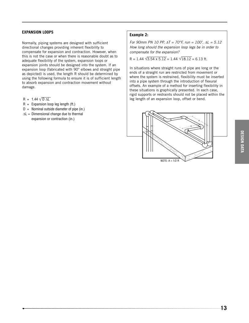
EXPANSION LOOPS
Normally, piping systems are designed with sufficientdirectional changes providing inherent flexibility tocompensate for expansion and contraction. However, whenthis is not the case or when there is reasonable doubt as toadequate flexibility of the system, expansion loops orexpansion joints should be designed into the system. If anexpansion loop (fabricated with 90° elbows and straight pipeas depicted) is used, the length R should be determined byusing the following formula to ensure it is of sufficient lengthto absorb expansion and contraction movement withoutdamage.
R = 1.44 D �LR = Expansion loop leg length (ft.)D = Nominal outside diameter of pipe (in.)�L = Dimensional change due to thermal
expansion or contraction (in.)
Example 2:
For 90mm PN 10 PP, �T = 70°F, run = 100’, �L = 5.12How long should the expansion loop legs be in order tocompensate for the expansion?
R = 1.44 3.54 x 5.12 = 1.44 18.12 = 6.13 ft.
In situations where straight runs of pipe are long or theends of a straight run are restricted from movement orwhere the system is restrained, flexibility must be insertedinto a pipe system through the introduction of flexuraloffsets. An example of a method for inserting flexibility inthese situations is graphically presented. In each case,rigid supports or restraints should not be placed within theleg length of an expansion loop, offset or bend.
NOTE: A = 1/2 R
DESIGN DATA
13

DESI
GN D
ATA
14
20
25
32
40
50
63
75
90
110
0.07
0.09
0.11
0.15
0.18
0.23
0.27
0.32
0.39
PP PIPE - PN10 - 150 PSI
size (d) S
0.09
0.13
0.18
0.28
0.43
0.69
0.97
1.39
2.05
lbs/ft
DIN 8077/8078, UNI 8318 & ISO DIS 15494
20
25
32
40
50
63
75
90
110
1.08
1.32
1.63
2.03
2.50
3.09
3.64
4.35
5.31
1.08
1.26
1.46
1.67
2.01
2.40
2.87
3.33
3.96
0.03
0.05
0.08
0.14
0.23
0.40
0.66
1.00
1.79
GIM - 90º ELBOW
size (d) E H lbs
0.51
0.63
0.79
0.87
1.08
1.32
1.65
1.93
2.32
Z
for socket fusion
Color: RAL 7032
20
25
32
40
50
63
1.08
1.32
1.65
2.03
2.48
3.11
0.83
0.96
1.14
1.40
1.67
2.01
0.03
0.04
0.07
0.13
0.23
0.40
HIM - 45º ELBOW
size (d) E H lbs
0.26
0.33
0.47
0.59
0.75
0.93
Z
for socket fusion
Except for item size (d), all other unspecified dimensions are in inches.
DESIGN DATA
20
25
32
40
50
63
75
90
110
1.08
1.32
1.63
2.05
2.52
3.13
3.64
4.35
5.30
1.08
1.24
1.46
1.69
2.05
2.46
2.80
3.21
3.92
0.04
0.07
0.10
0.18
0.32
0.55
0.81
1.23
2.18
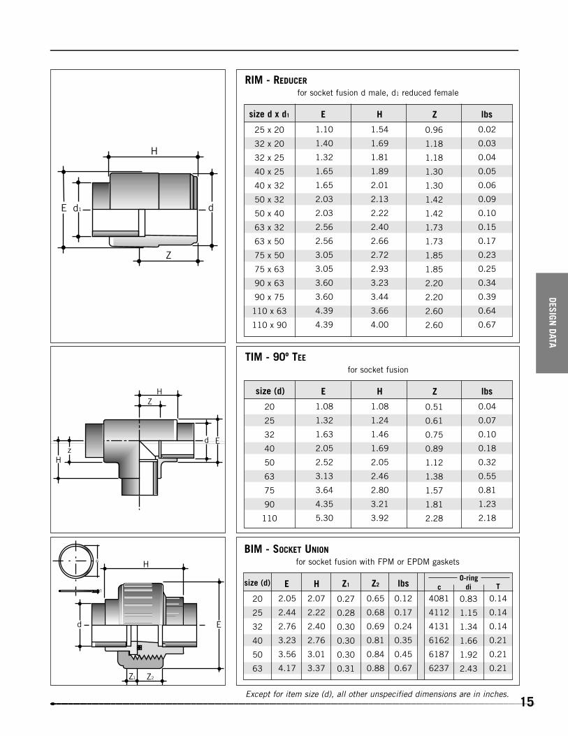
TIM - 90º TEE
size (d) E H lbs
0.51
0.61
0.75
0.89
1.12
1.38
1.57
1.81
2.28
Z
for socket fusion
20
25
32
40
50
63
2.05
2.44
2.76
3.23
3.56
4.17
2.07
2.22
2.40
2.76
3.01
3.37
0.65
0.68
0.69
0.81
0.84
0.88
BIM - SOCKET UNION
size (d) E H Z2 lbs
0.27
0.28
0.30
0.30
0.30
0.31
Z1
0.12
0.17
0.24
0.35
0.45
0.67
4081
4112
4131
6162
6187
6237
0.14
0.14
0.14
0.21
0.21
0.21
T
0.83
1.15
1.34
1.66
1.92
2.43
dic
for socket fusion with FPM or EPDM gaskets
25 x 20
32 x 20
32 x 25
40 x 25
40 x 32
50 x 32
50 x 40
63 x 32
63 x 50
75 x 50
75 x 63
90 x 63
90 x 75
110 x 63
110 x 90
1.10
1.40
1.32
1.65
1.65
2.03
2.03
2.56
2.56
3.05
3.05
3.60
3.60
4.39
4.39
1.54
1.69
1.81
1.89
2.01
2.13
2.22
2.40
2.66
2.72
2.93
3.23
3.44
3.66
4.00
0.02
0.03
0.04
0.05
0.06
0.09
0.10
0.15
0.17
0.23
0.25
0.34
0.39
0.64
0.67
RIM - REDUCER
size d x d1 E H lbs
0.96
1.18
1.18
1.30
1.30
1.42
1.42
1.73
1.73
1.85
1.85
2.20
2.20
2.60
2.60
Z
for socket fusion d male, d1 reduced female
O-ring
15Except for item size (d), all other unspecified dimensions are in inches.

DESI
GN D
ATA
16
20
25
32
40
50
63
75
90
110
1.08
1.32
1.65
2.05
2.48
3.05
3.58
4.29
5.20
1.44
1.57
1.75
1.91
2.19
2.52
2.83
3.19
3.66
0.02
0.04
0.06
0.09
0.14
0.21
0.32
0.51
0.81
MIM - SOCKET (COUPLING)
size (d) E H lbs
0.30
0.31
0.33
0.30
0.32
0.35
0.39
0.39
0.39
Z
for socket fusion
20
25
32
40
50
63
75
90
110
1.08
1.32
1.65
2.01
2.48
3.05
3.58
4.29
5.20
0.96
1.06
1.24
1.40
1.61
1.73
1.89
2.56
2.80
CIM - CAP
size (d) E H
0.02
0.02
0.04
0.07
0.11
0.19
0.26
0.47
0.77
lbs
end plain for socket fusion
20
25
32
40
50
63
75
90
110
0.24
0.28
0.28
0.33
0.33
0.35
0.39
0.45
0.49
1.39
1.67
2.06
2.47
2.98
3.67
4.33
5.06
6.12
QRM - STUBFLANGE
size (d) b d4
1.10
1.35
1.69
2.04
2.49
3.12
3.71
4.45
5.37
d3
0.79
0.87
0.96
1.02
1.14
1.30
1.48
1.69
1.93
0.22
0.24
0.26
0.22
0.22
0.22
0.26
0.30
0.30
H Z
0.02
0.02
0.04
0.06
0.08
0.14
0.22
0.33
0.53
lbs
(according to DIN norms) for socket fusion, with serrated face
To be used with ODB (d < 75) and ODC
Except for item size (d), all other unspecified dimensions are in inches.

DESIGN DATA
17
20
25
32
40
50
63
75
90
110
1/23/4
1
11/4
11/2
2
21/2
3
4
0.5
0.5
0.62
0.62
0.72
0.72
0.72
0.72
0.72
23/8
23/4
31/8
31/2
37/8
43/4
51/2
6
71/2
OAB - BACKING RING
d R (in) b K d2
0.62
0.62
0.62
0.62
0.62
0.78
0.78
0.78
0.78
3.75
4.04
4.5
5.12
5.23
6.34
7.2
7.59
9.02
D bolt holes
1.09
1.39
1.64
2.08
2.45
3.08
3.76
4.41
5.22
d6
4
4
4
4
4
4
4
4
8
0.48
0.62
0.99
1.19
1.32
1.94
2.42
2.68
4.07
lbs
M 12
M 12
M 12
M 16
M 16
M 16
M 16
M 16
M 16
bolt size
PN 10 PP with steel core, flange size: ANSI 150 for QRM stub flanges
Except for item size (d), all other unspecified dimensions are in inches.

DESI
GN D
ATA
18
20
25
32
40
50
63
75
90
110
150
150
150
150
150
150
150
150
150
0.30
0.46
0.66
0.95
1.39
2.32
4.42
7.62
11.22
VK DOUBLE BLOCKING BALL VALVE TRUE UNION
size (d) psilbs
4.02
4.49
4.96
5.55
6.46
7.83
8.39
10.51
10.83
H
PP Dimensions
2.17
2.56
2.91
3.39
3.90
4.72
5.94
7.32
8.66
1.93
2.32
2.60
2.95
3.43
3.98
4.88
5.59
6.54
E B
2.60
2.95
3.35
3.82
4.33
5.28
9.25
11.22
13.19
C
20
25
32
40
50
63
2.01
2.32
2.56
2.99
3.46
4.09
0.39
0.59
0.88
1.35
1.89
3.08
VT (L-PORT, T-PORT) THREE-WAY BALL VALVE
size (d) B lbs
2.09
2.48
2.80
3.31
3.82
4.57
E
2.56
2.99
3.35
3.94
4.41
5.39
C
3.23
3.74
4.29
5.12
6.10
7.20
4.37
5.00
5.71
6.73
7.95
9.37
Z H
0.93
1.20
1.55
1.58
2.05
2.22
I1
150
150
150
150
150
150
psi
1.06
1.26
1.44
1.69
2.03
2.34
B1
20
25
32
40
50
63
size (d)
Except for item size (d), all other unspecified dimensions are in inches.

Except for item size (d), all other unspecified dimensions are in inches.
DESIGN DATA
19
21/2
3
4
5
6
8
6.46
7.00
7.56
8.35
8.86
10.71
10.70
10.70
10.70
12.99
12.99
16.54
3.23
4.11
4.88
6.82
8.47
14.35
FK BUTTERFLY VALVE
d (in) B3 C lbs
0.75
0.75
0.75
0.91
0.91
0.91
f
4.33
4.33
4.33
4.33
4.33
4.80
C1
5.04
5.71
6.50
8.03
9.10
11.02
5.70
6.30
7.50
8.50
9.53
11.73
4.69
5.24
5.79
6.57
7.10
8.94
1.81
1.93
2.20
2.52
2.80
2.80
A min A max B1 Z
6.50
7.28
8.31
9.45
10.60
12.72
H
3.15
3.66
4.21
4.72
5.30
6.34
B2
10
12
9.76
12.01
8.27
9.65
26.45
41.89
FK 10" & 12" BUTTERFLY VALVE
I (in) B1 B2 lbs
4.49
4.49
A
15.95
18.70
H
10
12
.51
.67
.51
.17
4.92
5.51
4.92
5.51
1.06
1.06
I (in) J P Q
1.14
1.14
T
F12
F14
F12
F14
ISO mountpattern
21/2
3
4
5
6
8
d (in)
150
150
150
150
150
150
psi
150
150
psi
F05/F07
F07
F07
F07
F07
F07
ISO mountpattern
F05/F07
F07
F07
F07
F07
F07
ISO mountpattern

DESI
GN D
ATA
20
VR Y-PATTERN PISTON CHECK VALVE
20
25
32
40
50
63
75
90
4.92
5.71
6.50
7.48
8.27
9.45
11.81
12.80
2.17
2.56
2.91
3.39
3.90
4.72
4.06
4.53
size d A max E
2.80
3.27
3.70
4.29
4.69
5.61
6.93
7.60
B
4.27
4.92
5.61
6.46
7.74
9.41
9.49
10.24
5.41
6.18
7.03
8.07
9.59
11.57
-
-
Z H1
0.36
0.50
0.84
1.42
2.01
3.42
5.39
6.89
lbs
-
-
-
-
-
-
9.49
10.24
H
RV Y-PATTERN SEDIMENT STRAINER
150
150
150
90
90
90
90
60
psi
20
25
32
40
50
63
75
90
110
4.92
5.71
6.50
7.48
8.27
9.45
11.81
12.80
15.16
2.17
2.56
2.91
3.39
3.90
4.72
4.06
4.53
5.43
size d A max E
2.80
3.27
3.70
4.29
4.69
5.61
6.93
7.60
9.00
B
4.27
4.92
5.61
6.46
7.74
9.41
9.49
10.24
9.45
5.41
6.18
7.03
8.07
9.59
11.57
-
-
-
Z H1
0.33
0.43
0.65
1.05
1.49
2.42
3.48
4.22
6.60
lbs
-
-
-
-
-
-
9.49
10.24
12.70
H
150
150
150
90
90
90
90
60
60
psi
Except for item size (d), all other unspecified dimensions are in inches.

DESIGN DATA
21
VM PNEUMATIC DIAPHRAGM VALVE
Normally Open/Double-Acting
4.88
5.67
6.06
6.85
7.64
8.82
11.22
11.81
13.78
4.96
4.96
4.96
6.10
6.10
8.27
10.16
10.16
10.16
5.67
5.67
5.67
7.91
7.91
9.33
12.01
12.01
12.99
150
150
150
150
150
150
90
90
90
L D0 A NO/DA PSI
4.72
4.72
4.72
5.24
5.24
6.14
9.92
9.92
10.55
C NO/DA
1.02
1.02
1.02
1.57
1.57
1.57
2.17
2.17
2.72
B
20
25
32
40
50
63
75
90
110
size d
2.86
2.86
2.86
6.16
6.16
10.12
27.50
28.60
48.50
lbsNO/DA
6.89
6.89
6.89
9.61
9.61
11.50
12.80
12.80
13.98
0.63
0.75
0.91
1.06
1.26
1.54
1.73
2.01
-
2.60
2.60
2.60
4.06
4.06
4.92
7.36
7.36
10.55
150
150
150
150
150
150
90
90
90
A NC I C NC PSI
0.98
0.98
0.98
1.75
1.75
1.75
3.94
3.94
4.72
E1
M6
M6
M6
M8
M8
M8
M12
M12
M12
E
20
25
32
40
50
63
75
90
110
size d
4.07
4.07
4.07
8.80
8.80
15.29
33.30
34.10
56.10
Normally Closed
lbsNC
Except for item size (d), all other unspecified dimensions are in inches.

DESI
GN D
ATA
22
VM MANUALLY OPERATED DIAPHRAGM VALVE
20
25
32
40
50
63
75
90
110
3.74
3.74
3.74
4.96
4.96
5.83
8.86
8.86
11.61
4.88
5.67
6.06
6.85
7.64
8.82
11.22
11.81
13.78
size d A L
1.02
1.02
1.02
1.57
1.57
1.57
2.17
2.17
2.72
B
3.54
3.54
3.54
4.53
4.53
5.51
8.46
8.46
9.84
150
150
150
150
150
150
150
150
150
D PSI
1.54
1.54
1.54
3.30
3.30
5.28
16.50
16.50
23.00
lbs
20
25
32
40
50
63
75
90
110
0.98
0.98
0.98
1.75
1.75
1.75
3.94
3.94
4.72
0.63
0.75
0.91
1.06
1.26
1.54
1.73
2.01
-
size d E1 I
M6
M6
M6
M8
M8
M8
M12
M12
M12
E
Except for item size (d), all other unspecified dimensions are in inches.

SYSTEM SPECIFICATIONS
SYSTEMSPECIFICATION
S
23
Scope
This specification sheet covers the manufacturer’s (IPEX)requirements for PN10 pigmented, socket fusionPolypropylene pipe, valves, fittings and fusion equipment.The system is designed for use in demanding applicationsincluding, but not limited to, the pressurized handling ofaggressive chemicals, potable and pure water, chilled waterand foodstuffs.
Polypropylene Materials
Pipe material shall meet the requirements for a copolymer(Type II) polypropylene in accordance with ASTM D-2146.Fittings and valve material (wetted parts only) shall meet therequirements for PP-H (Homopolymer Type I) in accordancewith ASTM D-4101. All polypropylene materials used in themanufacturing of IPEX SF Polypro system shall be in compliance with CFR requirements for basic polypropylene.Pigment for all components shall be RAL 7032 in compliancewith CFR requirements for pigments suitable for contact withfoodstuffs, potable water and pharmaceutical use.
Pipe
IPEX pipe shall have outside diameters, wall thickness andallowable tolerances that conform to an SDR (StandardDimensional Ratio) of 11. Hydrostatic design basis of thepipe shall conform to ASTM D2837, DIN 8077/8078 andISO DIS 15494. Pipe shall be pressure rated for 150 psi(PN10) @ 68°F.
Fittings
All IPEX polypropylene fittings 20 mm (1/2") through 110 mm (4") shall be socket fusion style and shall be ratedfor 150 psi (PN10) @ 68°F.
The ID of all fitting shall provide an Interference Fit with pipeor spigot components (prior to the fusion heating cycle) andshall conform to DIN 16962. The amount of minimum andmaximum interference between pipe and fittings shall be regulated by ISO DIS 3609/15494 and DIN8077.
Valves
All polypropylene valves shall have either socket ends according to DIN 16962 or spigot ends according to DIN 8077/8078 or threaded ends according to ASA B 2.1.1945 or flanged ends according to ANSI B 16.1.
Glass reinforcement (GRF) of wetted parts shall not beallowed in any valve. (Consult individual cut sheet fordetailed valve specifications.)
Fusion Equipment
All socket fusion of IPEX polypropylene pipe, valves and fittings shall conform to the specification of ASTM D-2657.Fitting clamps with sharp edges can damage the fitting;equipment featuring such devices shall not be allowed.Welding of IPEX SF Polypro system components shall be performed with the use of IPEX socket fusion tools.
For joints from 20 mm (1/2") to 50 mm (11/2") IPEX PF063,PF110, Poly110M or Poly110P shall be used.
For joints 63 mm (2") to 110 mm (4") only IPEX Poly110mor Poly110P shall be used.
Socket Fusion Training
IPEX SF Polypro systems shall only be installed by IPEX trained installers.

VALVE SPECIFICATIONS
VALV
ESP
ECIF
ICAT
ION
S
24
VK SERIES: TRUE UNION END BALL VALVE
1.0 Ball Valves - VK
1.1 Material
• Valve body, stem, ball and unions shall be made of homopolymer polypropylene resin that is compatible with IPEX SF Polypro piping systems.
1.2 Seats
• Ball seats shall be Teflon® backed by EPDM or VITON o-rings.
1.3 Seals
• Seal material shall be EPDM or VITON (specifier must select one). The same material must be selected for seat back up o-rings (1.2).
2.0 Design Features
• Valves shall be blocking in both directions and shall have union ends.• Valves shall have a limited travel blocking carrier.• Body shall be single end entry.• The blocking device shall be adjustable with the valve installed.• 20 mm - 110 mm shall be full port.• All sizes shall have a spanner wrench incorporated in the handle.• 75 mm - 110 mm shall have integrally molded mounting pads.• 110 mm shall be trunnion style.• All valves shall have an expansion compensating groove on solid end.
2.1 Pressure Tested
• All valves shall have been pressure tested in both the open and closed positions by the manufacturer.
2.2 Pressure Rating
• Valves shall be rated as follows:20 mm - 110 mm - 150 psi at 73ºF
3.0 Ball valves shall be PP by IPEX or approved equal.

VALVESPECIFICATION
S
25
VT / VL SERIES: THREE-WAY TRUE UNION END BALL VALVE
1.0 Ball Valve - VT / VL
1.1 Material
• Valve body, stem, ball and unions shall be made of homopolymer polypropylene or resin that is compatible with IPEX SF Polypro piping system.
1.2 Seats
• Ball seats shall be Teflon®.
1.3 Seals
• Seal material shall be EPDM or VITON (specifier must select one).
2.0 Design Features
• All valves shall be molded to be true union (all three ports).• All ports shall have a Teflon® seat.• Valve design shall permit positive shut off of any of the three ports.• Balls shall be T-port or L-port (specifier must select one).• Thickness of valve body shall be the same at all three ports.• All valves shall have integrally molded mounting pads.
2.1 Pressure Rating
• Valves shall be rated at 150 psi at 73ºF.
3.0 Ball valves shall be PP by IPEX or approved equal.

VALV
ESP
ECIF
ICAT
ION
S
26
FK SERIES: BUTTERFLY VALVE
1.0 Butterfly Valves - FK
1.1 Material
• Valve body shall be made of glass reinforced PP(PPG) obtained from homopolymer polypropylene (PPH).
• Valve disc shall be made of homopolymer polypropylene or compatible with IPEX SF Polypro piping system.
• Valve shaft shall be made of 420 stainless steel.
1.2 Seats
• Liner boot shall be EPDM or VITON (specifier to select one).
1.3 Seals
• O-rings shall be EPDM or VITON (specifier to select one).
2.0 Design Features
• Shaft shall have standard ISO square dimensions for direct mounting of actuators.• Disc seating shall be provided by a pyramidal elastomeric liner boot.• Liner shall:
a) completely isolate valve body from flow, andb) function as flange gasket on both sides of the valve
• Body cavity shall feature a special serrated surface to prevent liner slippage and compression.• Disc, seats and seals to be the only wetted parts.• A Teflon® seated double elastomeric seal packaging shall prevent the stainless steel shaft from becoming wetted.• Valve shall be bubble tight and of wafer or lug design.• Lug style valves shall feature lugs permanently integrated during molding.
2.1 Pressure Rating
• Valves shall be rated at 150 psi at 73ºF.
3.0 Butterfly valves shall be by IPEX or approved equal.

VALVESPECIFICATION
S
27
VR SERIES: PISTON CHECK VALVE
1.0 Check Valves - VR
1.1 Material
• Valve body and piston shall be made of pigmented polypropylene that is compatible with IPEX SF Polypro pipingsystem.
1.2 Seats
• Seat material shall be EPDM or VITON (specifier must select one).
1.3 Seals
• Seal material shall be EPDM or VITON (specifier must select one).
2.0 Design Features
• Valve body shall have true union ends (20 mm to 63 mm) and solid threaded or socket ends (75 mm - 90 mm).• All valves shall be y - pattern globe style.• All valves shall be gravity operated.• The weight shall be totally encapsulated inside the piston.• Valve shall work both in horizontal and vertical lines, without minimum column requirements.• Servicing of the valves shall be possible without removal from the line.
2.1 Pressure Rating
• Valves shall be rated as follows:
20 mm - 63 mm - 150 psi at 73ºF75 mm - 90 psi at 73ºF90 mm - 60 psi at 73ºF
3.0 Piston Check valves shall be by IPEX or approved equal.

VALV
ESP
ECIF
ICAT
ION
S
28
RV SERIES: SEDIMENT STRAINER
1.0 Strainers - RV
1.1 Material
• Strainer body shall be made of pigmented polypropylene that is compatible with IPEX SF Polypro piping system.
1.2 Seals
• Seal material shall be EPDM or VITON (specifier must select one).
1.3 Screens
• Screens shall be:
PPStainless Steel
2.0 Design Features
• Strainer shall be Y - pattern style and shall have true union ends 20 mm - 63 mm) and socket (75 mm - 110 mm).• It shall be possible to service the valve without removing it from the line.• Following mesh sizes shall be available:
13, 15, 19, 30 (PVC)19 (stainless steel)
2.1 Pressure Rating
• Strainers shall be rated as follows:
20 mm - 63 mm - 150 psi at 73ºF75 mm - 90 psi at 73ºF90 mm - 110 mm - 60 psi at 73ºF
3.0 Sediment Strainers shall be by IPEX or approved equal.

VALVESPECIFICATION
S
VM SERIES: PNEUMATIC DIAPHRAGM VALVE
1.0 Pneumatic Diaphragm Valves - VM
1.1 Material
• Valve body shall be made of polypropylene resin that is compatible with IPEX SF Polypro piping system.
• Valve bonnets shall be made of high temperature, high strength glass-filled polypropylene.
1.2 Diaphragm
• Diaphragm material shall be EPDM, VITON or PTFE faced with elastomeric backing (specifier must select one).
2.0 Design Features
• All valves shall be true union (20 mm - 63 mm) or spigot (20 mm - 110 mm).• All valves shall be weir style for throttling applications.• All bodies to be used with EPDM or VITON diaphragms shall feature raised molded sealing rings (concentric).• All bodies to be used with PTFE diaphragms shall be machined flat.• All PTFE diaphragms shall feature a raised molded ring to combine sealing performance and longer life.• All through bolts shall be 304SS.• Bolts will thread directly into integrally molded brass inserts in the bonnet.• All manual valves shall have a rising valve indicator.• Bodies of all sizes and material shall have mounting brass inserts.
2.1 Design Features - Actuators
• All springs shall be cut from spring grade steel for maximum memory life and epoxy coated for maximum chemical resistance.
• Fail safe to open and double-acting actuators shall feature weak springs located in the center of the actuator.• Fail safe to close actuators shall feature three concentric springs located in the middle of the actuator.• All actuators (20 mm - 90 mm) shall be glass-filled polypropylene.
The following accessories shall be available for all actuators:position indicator, stroke limiter, stroke limiter with position indicator,limit switch, 4-20 MA positioner, limit switch box, solenoids
• All actuators (1/2" thru 3") shall feature a smooth top (no nut holes) for cleanliness.• Edge of actuator membrane shall be inside of actuator protective housing.
2.2 Pressure Rating
• Valves shall be rated as follows: 20 mm - 110 mm - 150 psi at 73º
3.0 VM Series Diaphragm valves shall be by IPEX or approved equal.
29

VALV
E SP
ECIF
ICAT
ION
S
30
VM SERIES: MANUAL DIAPHRAGM VALVE
1.0 Manual Diaphragm Valves - VM
1.1 Material
• Valve body shall be made of polypropylene resin that is compatible with IPEX SF Polypro piping system.
• Valve bonnets shall be made of high temperature, high strength glass-filled polypropylene.
1.2 Diaphragm
• Diaphragm material shall be EPDM, VITON or PTFE faced with elastomeric backing (specifier must select one).
2.0 Design Features
• All valves shall be true union (20 mm - 63 mm) or spigot (20 mm - 110 mm).• All valves shall be weir style for throttling applications.• All bodies to be used with EPDM or VITON diaphragms shall feature raised molded sealing rings (concentric).• All bodies to be used with PTFE diaphragms shall be machined flat.• All PTFE diaphragms shall feature a raised molded ring to combine sealing performance and longer life.• All through bolts shall be 304SS.• Bolts will thread directly into integrally molded brass inserts in the bonnet.• All manual valves shall have a rising valve indicator.• Bodies of all sizes and material shall have mounting brass inserts.
2.1 Pressure Rating
• Valves shall be rated as follows:
20 mm - 110 mm - 150 psi at 73ºF
3.0 VM Series Diaphragm valves shall be by IPEX or approved equal.
Optional: All PP valves (20 mm - 63 mm) can be true union end design.

HANDLING AND INSTALLATION
HAN
DLING AN
DIN
STALLATION
31
1
2
Appliance for manual joining of pipes and fittings by socket welding.
Socket Weld Installation
Socket welding involves fusing of the pipe in the socket of the fitting. The joint is made by simultaneously fusing the maleand female surfaces by means of special manual or automatic heating device. The welding appliance, in its simplest form, is composed of a heating surface on which a series of heating bushes are mounted. The appliance is completed by an appropriate heating system complete with an automatic temperature controller. No additional materials are required for thistype of welding. It should be noted that socket welding does not affect the chemical resistance of the polypropylene, nor doesit influence the chemical resistance or pressure resistance of the assembled pipes and fittings.
Select the heating bush and the heating spigot of therequired diameters, insert them and secure them to theheating tool.
Carefully clean the contact surfaces. When choosingthe type of liquid detergent, use recommended products such as: trichloroethane, chloroethene, ethylalcohol and isopropyl alcohol.
Instructions
These instructions are for the use of IPEX manual type welding equipment. The use of automatic and semi-automatic appliances, which are particularly suitablefor diameters greater than 63 mm, calls for a specificworking knowledge of the welding tool. In this case,adhere strictly to the specific tool instructions.
Manual-Type Welding Equipment

HAN
DLIN
G AN
DIN
STAL
LATI
ON
32
Set the temperature of the heating tool. To form the joint correctly, the temperature should be set between 250 and 270ºC.
When the appliance has reached the preset temperature, check the temperature of the heating surface using a fastacting thermoprobe.
5
Outside Diameter
de (mm)
20
25
32
40
50
63
75
90
110
Chamfer depth
Sm
4 mm
5/32 inches
5 mm
1/5 inches
Cut the pipe at right angles and chamfer the newly cut edge.
3
4
Polypropylene Fittings for Socket Welding. Chamfer dimensions.Table 1

HAN
DLING AN
DIN
STALLATION
33
6
7
8
Insertion Length L1: indicates the maximum length ofinsertion of the heated pipe into the socket of the fitting.(Table 2)
The insertion depth of the pipe into the fitting varies bydiameter.
Mark the pipe at the insertion length L1.
Mark a longitudinal reference line on the outside of the pipe and the fitting to prevent the two parts fromrotating while the joint is being made.
Clean the fitting and pipe from any traces of oil or grease on the weld surfaces with an approved cleaning agentsuch as isopropyl alcohol.
D
L1
L1
20
14
0.55
25
15
0.58
32
17
0.67
40
18
0.70
50
20
0.78
63
26
1.00
75
29
1.14
90
32
1.25
110
35
1.37mm
inch
Insertion Depth TableTable 2

HAN
DLIN
G AN
DIN
STAL
LATI
ON
34
9
10
Heating, Welding and Cooling Times
(T ) For a correctly executed weld werecommend using pipe wall thicknesses greater than 2 mm(0.08").
When the minimum heating time has elapsed, quicklyremove the elements from the heating bushings and fitthe pipe into the socket for the entire insertion L1marked previously. Do not turn the pipe in the sockets;Ensure the longitudinal reference marks are perfectlyaligned.
Check that the thermostat green light is on steady or, ifexternal conditions requires the use of a Temperstick*, usethe correct Temperstick to check the bushings temperature(DO NOT USE THE STICK ON THE PARTS OF THEBUSHINGS THAT WILL COME IN CONTACT WITH PIPE OR FITTINGS). Briefly and simultaneously engage both pipe andfitting with their respective bushing to determine interference.If substantial more resistance is offered by either the pipe orthe fitting, begin your insertion with just that one item. Startthe insertion of the second item once the first has reachedthe bushing half point. If same resistance is observed, startboth pipe and fitting insertion simultaneously. Once the markon the pipe reaches the edge of the female bushing and the top of the fitting reaches the stop on the male bushing apply justenough pressure to prevent “kick-back” and begin the heating time count as shown in Table 3.
* Should welding be performed outdoors in adverse (cold and/or windy) weather conditions, it is advisable to double checkthe thermostat reading with Temperstick. Should the Temperstick ascertain an insufficient tool temperature, simply increaseby small increments the thermostat setting until the Temperstick deposit on the tool evaporates. After any changes to thetemperature dial, the red light will come on. You must wait for the green indicator to light before using the Temperstick.
Polypropylene pipes to: DVS 2207 Part 11
2.5
2.7
3
3.7
4.6
3.6
4.3
6.1
6.3
5
7
8
12
16
24
30
40
50
20
25
32
40
50
63
75
90
110
Minimum Thickness
(mm)(T)
Heating Time
(s)
Welding Time
(s)
Cooling Time
(min)
Diameter(mm)
4 2
6 4
8 6
10 8
Table 3
HAN
DLING AN
DIN
STALLATION
35
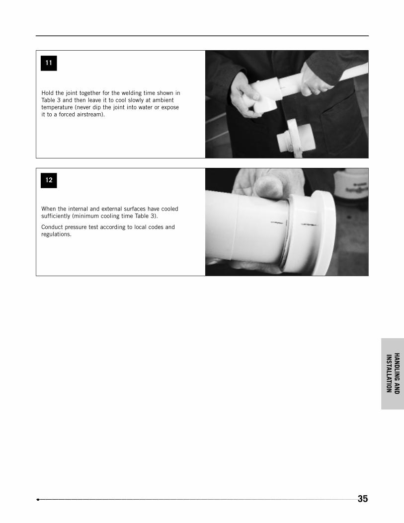
11
12
When the internal and external surfaces have cooledsufficiently (minimum cooling time Table 3).
Conduct pressure test according to local codes and regulations.
Hold the joint together for the welding time shown inTable 3 and then leave it to cool slowly at ambient temperature (never dip the joint into water or expose it to a forced airstream).

HAN
DLIN
G AN
DIN
STAL
LATI
ON
36
Socket Fusion Polypropylene Bench Socket Fusion Joining Kit
Socket Fusion Polypropylene (SF Polypro) can be easily and efficiently joined using the IPEX Bench Socket Fusion Tool. Thetool, available in both manual and hydraulic versions, comes complete with all the parts and accessories needed to socketweld the entire range of 20 mm to 110 mm SF Polypro products. The kit includes a self-aligning frame; removable stand withtool box; thermostat-controlled heating mirror; master pipe, fitting clamps and all their reducers; heater bushing; patentedinsertion-depth selector; and manual or hydraulic controls.
The IPEX Bench Fusion Tool is the natural choice when performing larger size socket welds or when completing a largenumber of welds requiring maximum accuracy from the first to the last.
in 1/2 3/4 11/4 11/2 2 3 4
mm 20 25 40 50 63 90 110
Socket Fusion Procedure
It is strongly recommended that your local IPEX
representative demonstrate the socket fusion procedure
before you attempt to assemble SF Polypro systems. Use
only IPEX socket fusion tools. They are designed specifically
for our systems, with components that are dimensionally
matched. Do not attempt to install a system of mixed
brands.
Preparing the Machine
• Assemble the
machine and stand
at the work area.
Select the correct
size of
V-blocks for the
fittings. Select the
inserts for the pipe
clamps and fasten
them in place using
the allen wrench provided. Inserts are not required for 4" or
110 mm pipe.
• Set the insertion
depth selector stop
on the end of the
machine to the
correct size. These
settings are in
millimeters and are
pre-set at the factory.
The inch equivalents are as follows:
Preparing the Heating Tool
• Be sure the mirror is
clean. Dirty or greasy
mirror surfaces will
reduce heat transfer
and joint strength.
CAUTION:
Handle the heater
bushings carefully.
Damage to the Teflon
coating on the heater bushings can cause poor welds.
• Bolt the heater bushings securely to the mirror with the
hardware provided. Plug the heater into a grounded 110-
volt outlet. Be sure the outlet is protected by circuit
breakers or fuses. Using other electrical devices on the
same power source causes amperage loss and can also
cause bad welds.
• Set the temperature
selector to 260ºC
(500ºF) and wait for
the temperature light
indicator to go off.
The temperature of
the heater bushings
must be between
253ºC (488ºF) and
288ºC (550ºF).
HAN
DLING AN
DIN
STALLATION
37
If external conditions require the use of a Temperstick*, use
the correct Temperstick to check the bushings temperature.
CAUTION:
Do not use the Temperstick on the parts of the bushings that
will come in contact with pipe or fittings.
*Should welding be performed outdoors in cold and/or windy
weather conditions, it is advisable to double-check the
thermostat reading with a Temperstick. Should the
Temperstick indicate insufficient tool temperature, simply
increase the thermostat setting by small increments until the
Temperstick deposit on the tool evaporates. After any
changes to the temperature dial, the red light will come on.
You must wait for the green indicator to light before using the
Temperstick.
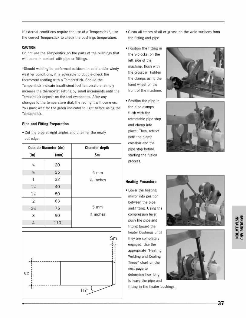
Pipe and Fitting Preparation
• Cut the pipe at right angles and chamfer the newly
cut edge.
• Clean all traces of oil or grease on the weld surfaces from
the fitting and pipe.
• Position the fitting in
the V-blocks, on the
left side of the
machine, flush with
the crossbar. Tighten
the clamps using the
hand wheel on the
front of the machine.
• Position the pipe in
the pipe clamps
flush with the
retractable pipe stop
and clamp into
place. Then, retract
both the clamp
crossbar and the
pipe stop before
starting the fusion
process.
Heating Procedure
• Lower the heating
mirror into position
between the pipe
and fitting. Using the
compression lever,
push the pipe and
fitting toward the
heater bushings until
they are completely
engaged. Use the
appropriate “Heating,
Welding and Cooling
Times” chart on the
next page to
determine how long
to leave the pipe and
fitting in the heater bushings.
Outside Diameter (de)
(in) (mm)
20
25
32
40
50
63
75
90
110
Chamfer depth
Sm
4 mm
5/32 inches
5 mm
1/5 inches
1/2
3/4
1
11/4
11/2
2
21/2
3
4
HAN
DLIN
G AN
DIN
STAL
LATI
ON
38
• The following charts show the appropriate time, that the
pipe and fitting should be held on the heater bushings.
Heating time starts from the moment of full insertion of both
pipe and fitting.
Specifically:
If the pipe and fitting do not fit tightly on the heater bushing,
the heating time should be started when the components
have swelled to just contact the surface of the heater bushings.
(T ) For a correctly executed weld, we recommend using pipewall thicknesses greater than 2 mm (0.08").
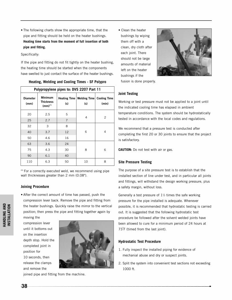
Joining Procedure
• After the correct amount of time has passed, push the
compression lever back. Remove the pipe and fitting from
the heater bushings. Quickly raise the mirror to the vertical
position; then press the pipe and fitting together again by
moving the
compression lever
until it bottoms out
on the insertion
depth stop. Hold the
completed joint in
position for
10 seconds, then
release the clamps
and remove the
joined pipe and fitting from the machine.
• Clean the heater
bushings by wiping
them off with a
clean, dry cloth after
each joint. There
should not be large
amounts of material
left on the heater
bushings if the
fusion is done properly.
Joint Testing
Working or test pressure must not be applied to a joint until
the indicated cooling time has elapsed in ambient
temperature conditions. The system should be hydrostatically
tested in accordance with the local codes and regulations.
We recommend that a pressure test is conducted after
completing the first 20 or 30 joints to ensure that the project
is satisfactory.
CAUTION: Do not test with air or gas.
Site Pressure Testing
The purpose of a site pressure test is to establish that the
installed section of line under test, and in particular all joints
and fittings, will withstand the design working pressure, plus
a safety margin, without loss.
Generally a test pressure of 11/2 times the safe working
pressure for the pipe installed is adequate. Whenever
possible, it is recommended that hydrostatic testing is carried
out. It is suggested that the following hydrostatic test
procedure be followed after the solvent welded joints have
been allowed to cure for a minimum period of 24 hours at
73oF (timed from the last joint).
Hydrostatic Test Procedure
1. Fully inspect the installed piping for evidence of
mechanial abuse and dry or suspect joints.
2. Split the system into convenient test sections not exceeding
1000 ft.
Heating, Welding and Cooling Times - SF Polypro
Polypropylene pipes to: DVS 2207 Part 11
2.5
2.7
3
3.7
4.6
3.6
4.3
6.1
6.3
5
7
8
12
16
24
30
40
50
20
25
32
40
50
63
75
90
110
Heating Time
(s)
Welding Time
(s)
Cooling Time
(min)
Diameter
(mm)
4 2
6 4
8 6
10 8
MinimumThickness(mm)(T)

HAN
DLING AN
DIN
STALLATION
39
Contact your nearest IPEX Customer Service Center with any questions regarding applications or specifications
not included in this manual.
3. Slowly fill the pipe section with cold water taking care to
evacuate all entrapped air in the process. Use air release
valves at any high points in the system. Do not pressurize
at this stage.
4. Leave the section for at least 1 hour to allow equilibrium
temperature to be achieved.
5. Check the sytem for leaks. If clear, check for and remove
any remaining air and increase pressure up to 50 psi. Do
not pressurize further at this stage.
6. Leave the section pressurized for 10 minutes, if the
pressure decays, inspect for leaks. If the pressure remains
constant, slowly increase the hydrostatic pressure to 11/2
times the nominal working pressure.
7. Leave the section pressurized for a period not exceeding
1 hour. During this time the pressure should not change.
If there is a significant drop in static pressure, or extended
times are required to achieve pressure, either joint leakage
has occurred or air remains in the line. Inspect for leakage
and if none is apparent, reduce the pressure and check for
trapped air. This must be removed before further
pressurization is commenced.
Any joint leaks should be repaired and allowed to fully
cure before re-pressurizing.

NOTES

WARRANTY: All IPEX products are guaranteed against defects resulting from faulty workmanship ormaterials. If any such product is found to be defective by reason of faulty workmanship or materials,upon written notice and return of the product, the defective product will be replaced by IPEX freeof charge, including shipping charges for the replacement product. Claims for labour costs and otherexpenses required to replace such defective product or to repair any damage resulting from the usethereof will not be allowed by IPEX. Our liability is limited to the price paid for the defective product.IPEX will not be bound by any warranty, other than above set forth, unless such warranty is inwriting.
This literature is published in good faith and is believed to be reliable. However, IPEX does notrepresent and/or warrant in any manner the information and suggestions contained in this brochure.Data presented is the result of laboratory tests and field experience.
IPEX maintains a policy of ongoing product improvement. This may result in modificationof features and/or specifications without notice.
MNINNAIP030409© 2003 IPEX IND0035UC
SALES AND CUSTOMER SERVICE
Canadian Customers call
Toll free: (866) 473-9462
U.S. Customers call
Toll free: (800) 463-9572
www. ipex inc.com
About IPEX
IPEX is a leading supplier of thermoplastic piping systems. We provide our
customers with one of the world’s largest and most comprehensive product
lines. All IPEX products are backed by over 50 years of experience. With
state-of-the-art manufacturing facilities and distribution centers across
North America, the IPEX name is synonymous with quality and
performance.
Our products and systems have been designed for a broad range of
customers and markets. Contact us for information on:
• PVC, CPVC, PP, ABS, PEX and PE pipe and fittings (1/4" to 48")
• Industrial process piping systems
• Double containment systems
• Acid waste systems
• High purity systems
• Municipal pressure and gravity piping systems
• Plumbing and mechanical pipe systems
• Electrical systems
• Telecommunications and utility piping systems
• Irrigation systems
• Radiant heating systems


![Socket Fusion Fittings - dpk3n3gg92jwt.cloudfront.net · Socket Fusion Fittings ... 25 ‐ 20735 910 337 0.035 37 A 32 ‐ 20735 910 342 0.051 43 A ... (R/Rp BS Thread) [inch] L1](https://static.documents.pub/doc/80x56/5b0707907f8b9ac33f8da815/socket-fusion-fittings-fusion-fittings-25-20735-910-337-0035-37-a-32.jpg)

