Page 1
WELLBORE PRESSURE PREDICTION AFTER PIPE CONNECTION
OPERATION IN UNDERBALANCED DRILLING
REZA CHERAGHI KOOTIANI
A thesis submitted in fulfilment of the
requirements for the award of the degree of
Doctor of Philosophy (Petroleum Engineering)
Faculty of Chemical and Energy Engineering
Universiti Teknologi Malaysia
NOVEMBER 2015
Page 2
iii
I would like to dedicate this thesis to my family, Iraj, and Javad who have been great
inspiration in completing this thesis.
Page 3
iv
ACKNOWLEDGEMENT
I wish to appreciate first and foremost the Almighty God for his great mercies
towards me and his tremendous help in helping me get to this stage of this my
academic journey. Without his help I would not have achieved anything. I praise him
for all the supply.
My profound many thanks go to my untiring supervisor, Professor Dr. Ariffin
Bin Samsuri who has always been there to attend to my inquiries and to give me the
necessary supervisory attention required. Your humility has been a huge boost in
propelling me to prosecute this research successfully.
I wish to express my profound gratitude to my family. Your encouragement,
support and prayers have seen me through this challenging journey. Besides, I would
like to thank the authority of Universiti Teknologi Malaysia (UTM) for providing me
with a good environment and facilities to complete this project.
Page 4
v
ABSTRACT
In underbalanced drilling (UBD), bottom hole pressure (BHP) must be
maintained in the defined limit. Maintaining underbalanced drilling conditions after
pipe connection operation is required for the success of underbalanced drilling
operations. Modeling and simulation of gas-liquid two phase flow in an UBD
operation is very significant in order to accurately predict the wellbore pressure and
other parameters of two phase flow. After pipe connection operation in UBD, upon
restarting mud circulation system, frictional pressure influenced the BHP and the
fluid slugs in the drill string are transferred into the annulus. Therefore, the
hydrostatic pressure will increase and UBD pipe connection operations create a BHP
vibration, which is a critical point. This particular time can reduce the benefits
obtained to drill the well in an underbalanced environment. In this study, a
mechanistic steady state gas-liquid two phase flow model was used to simulate the
two phase flow after pipe connection operation in UBD. Simulation was carried out
to predict the parameters; such as wellbore pressure, liquid holdup, and velocities of
the two phases at different flow patterns, namely slug, bubble, churn, dispersed
bubble, and annular flow. In order to predict wellbore pressure, a steady state model
was developed to predict flow patterns, pressure gradient, and liquid holdup for gas-
liquid flow in vertical annulus and drill string. The model included flow pattern
transition models and hydrodynamic models for individual flow pattern. The model
equations along with appropriate constitutive relations formed a system of coupled
drift flux, momentum, and energy equations, which were solved using the well
known iterative Newton Raphson method. All model equations were implemented in
a computer program named Fortran 95. The effect of gas and liquid flow rates, and
choke pressure on the wellbore pressure, particularly in the BHP was evaluated
numerically. In order to validate the results of the developed model, they were
compared with actual field data and the results of the WELLFLO software using
different mechanistic models. The results revealed that the two phase model
developed can accurately predict wellbore pressure, particularly BHP, wellbore
temperature, gas/liquid velocities, and two phase flow patterns.
Page 5
vi
ABSTRAK
Dalam penggerudian imbang bawah (UBD), tekanan dasar lubang (BHP)
mesti dikekalkan pada had yang ditetapkan. Pengekalan keadaan penggerudian
imbang bawah selepas operasi penyambungan paip adalah diperlukan bagi menjamin
kejayaan operasi penggerudian terbabit. Pemodelan dan penyelakuan aliran dua fasa
gas-cecair bagi suatu operasi UBD adalah sangat penting bagi meramal secara tepat
tekanan lubang telaga dan parameter lain dalam aliran dua fasa. Selepas selesainya
operasi penyambungan paip dalam UBD, sebaik sahaja bermulanya semula
pengedaran lumpur dalam sistem, tekanan geseran akan mempengaruhi BHP dan
slug bendalir di dalam rentetan gerudi akan berubah kedudukan ke anulus. Dengan
itu, tekanan hidrostatik akan meningkat dan operasi penyambungan paip dalam UBD
menghasilkan getaran BHP yang merupakan suatu titik kritikal. Keadaan ini boleh
mengurangkan manfaat yang diperoleh daripada penggerudian telaga dalam
persekitaran imbang bawah. Dalam kajian ini, model mekanistik aliran keadaan
mantap dua fasa gas-cecair telah digunakan untuk menyelaku aliran dua fasa terbabit
selepas operasi penyambungan paip dalam UBD. Penyelakuan dilaksanakan untuk
meramal parameter misalnya tekanan lubang telaga, tahanan cecair, dan halaju dua
fasa pada pelbagai corak aliran, iaitu slug, gelembung, pusaran, gelembung tersebar,
dan anulus. Dalam usaha untuk meramal tekanan lubang telaga, suatu model keadaan
mantap telah dibangunkan bagi meramal corak aliran, kecerunan tekanan, dan
tahanan cecair untuk aliran gas-cecair di dalam anulus tegak dan rentetan gerudi.
Model terbabit merangkumi model peralihan corak aliran dan model hidrodinamik
untuk corak aliran yang berlainan. Persamaan model itu berserta dengan hubungan
juzuk yang sesuai telah membentuk sistem gandingan fluks sesaran, momentum dan
persamaan tenaga yang boleh diselesaikan menerusi penggunaan kaedah lelaran
Newton Raphson. Semua persamaan model diaplikasi menggunakan program
komputer, Fortran 95. Kesan gas dan kadar aliran cecair serta tekanan pencekik
terhadap tekanan lubang telaga terutama dalam BHP dinilai secara berangka. Dalam
usaha untuk mengesahkan keputusan model terbabit, semua pencapaiannya
dibandingkan dengan data sebenar medan dan hasil daripada perisian WELLFLO
yang menggunakan pelbagai model mekanistik. Hasil kajian yang diperoleh
menunjukkan bahawa model dua fasa yang dibangunkan boleh meramal secara tepat
tekanan lubang telaga terutama BHP, suhu lubang telaga, halaju gas/cecair dan corak
aliran dua fasa.
Page 6
vii
TABLE OF CONTENTS
CHAPTER TITLE PAGE
DECLARATION ii
DEDICATION iii
ACKNOWLEDGMENT iv
ABSTRACT v
ABSTRAK vi
TABLE OF CONTENTS vii
LIST OF TABLES xii
LIST OF FIGURES xiv
LIST OF ABBREVIATIONS xvii
LIST OF NOMENCLATURES xix
LIST OF APPENDICES xxii
1 INTRODUCTION 1
1.1 Background of Study 1
1.2 Problem Statement 3
1.3 Research Objective 6
1.4 Scope of Study 7
1.5 Significance of Study 7
2 LITERATURE REVIEW 9
2.1 Underbalanced Drilling 9
2.1.1 Purposes of UBD 11
2.1.2 Underbalanced Drilling Techniques 14
2.1.2.1 Selection of Underbalanced Drilling
Technique
15
Page 7
viii
2.1.3 Limitations 20
2.1.4 Equipment in Underbalanced Drilling
Systems
21
2.1.4.1 Surface Equipment 21
2.1.4.2 Downhole Equipment 23
2.1.5 Mud Circulation Systems 24
2.1.6 Drill-String 25
2.2 Two Phase Flow 26
2.2.1 Two-Phase Flow Patterns 28
2.2.2 Two Phase Flow Pattern Prediction Models 33
2.2.2.1 Fluid Properties 33
2.2.2.2 Velocity Profile 35
2.2.2.3 Channel Configuration 40
2.2.3 Underbalanced Drilling Flow Patterns 44
2.3 Bottom hole Pressure Prediction 45
2.3.1 Manage Pressure Drilling 47
2.3.2 BHP Prediction During UBD Pipe
Connection Operations
48
2.3.2.1 Bottom Hole Pressure Vibrations 48
2.4 Steady State Models Approach in UBD Operations 51
2.5 Summary of Literature Review 56
3 METHODOLOGY 60
3.1 Mechanistic Steady State Model Development 60
3.2 Computer Program 64
3.3 Algorithm Steps 67
3.4 Mechanistic Steady State Model Development
Validation
74
3.4.1 Well Agave 301 74
3.4.2 Well Muspac 53 76
3.4.3 Well Parsi70 78
4 MECHANISTIC STEADY STATE FLOW MODELING 81
4.1 Theory of Modeling 81
Page 8
ix
4.1.1 Gas/Liquid Two Phase Flow 81
4.1.1.1 Two Phase Flow Definition and
Basic Parameters
82
4.1.2 Two Phase Flow Concepts 85
4.1.3 Momentum Equation 89
4.1.3.1 Frictional Component 91
4.1.3.2 Gravitational Component 92
4.1.3.3 Acceleration Component 92
4.1.4 Drift Flux Model 94
4.1.5 Classification of Fluids and Flow Regimes 95
4.1.5.1 The Reynolds Number 96
4.1.5.2 The Fanning Friction Factor 97
4.1.6 Gas- Liquid Two Phase Flow Patterns 98
4.1.7 Two Phase Flow Pattern Transition Models 100
4.1.7.1 Annuli Flow Patterns Prediction
Models
100
4.1.7.2 Drill-String Flow Patterns Prediction
Models
106
4.2 Steady State Model Development 109
4.2.1 Annulus Bubble Flow Prediction Model 109
4.2.2 Annulus Dispersed Bubble Flow Prediction
Model
111
4.2.3 Annulus Slug Flow Prediction Model 112
4.2.3.1 Physical Model of Fully Developed
Slug Flow
115
4.2.3.2 Physical Model of Developing Slug
Flow
118
4.2.4 Annulus Annular Flow Prediction Model 122
4.2.5 Annulus Churn Flow Prediction Model 127
4.2.6 Drill-string Bubble Flow Prediction Model 128
4.2.7 Drill-string Dispersed Bubble Flow Prediction
Model
128
4.2.8 Drill-string Slug Flow Prediction Model 128
4.2.9 Bit Flow Model 130
4.3 Computer Program Algorithm Flowchart 131
Page 9
x
5 RESULTS AND DISCUSSIONS 133
5.1 Steady State Model Development Validation 133
5.1.1 Wellbore Pressure Prediction of Well Agave
301
133
5.1.2 Wellbore Pressure Prediction of Well Muspac
53
136
5.1.3 Wellbore Pressure Prediction of Well Parsi70 138
5.2 Two Phase Flow Patterns Prediction of Well Agave
301
139
5.3 Two Phase Flow Patterns Prediction of Well Muspac
53
142
5.4 Two Phase Flow Pattern Maps 144
5.4.1 Two Phase Flow Pattern Maps of Well Agave
301
144
5.4.2 Two Phase Flow Pattern Maps of Well
Muspac 53
149
5.5 Effect of Drilling Fluid Flow Rate on the Wellbore
Pressure
153
5.5.1 Effect of Drilling Fluid Flow Rate on the
Wellbore Pressure of Well Agave 301
153
5.5.2 Effect of Drilling Fluid Flow Rate on the
Wellbore Pressure of Well Muspac 53
154
5.6 Effect of Drilling Fluid Flow Rate on the Flow Patterns 155
5.6.1 Effect of Drilling Fluid Flow Rate on the
Flow Patterns of Well Agave 301
155
5.6.2 Effect of Drilling Fluid Flow Rate on the
Flow Patterns of Well Muspac 53
157
5.7 Effect of N2 Gas Flow Rate on the Wellbore Pressure 159
5.7.1 Effect of N2 Gas Flow Rate on the Wellbore
Pressure of Well Agave 301
159
5.7.2 Effect of N2 Gas Flow Rate on the Wellbore
Pressure of Well Muspac 53
160
5.8 Effect of N2 Gas Flow Rate on the Flow Patterns 161
5.8.1 Effect of N2 Gas Flow Rate on the Flow
Patterns of Well Agave 301
161
5.8.2 Effect of N2 Gas Flow Rate on the Flow
Patterns of Well Muspac 53
164
5.9 Effect of Choke Pressure on the Wellbore Pressure 165
Page 10
xi
5.9.1 Effect of Choke Pressure on the Wellbore
Pressure of Well Agave 301
165
5.9.2 Effect of Choke Pressure on the Wellbore
Pressure of Well Muspac 53
166
5.10 Effect of Choke Pressure on the Flow Patterns 167
5.10. 1 Effect of Choke Pressure on the Flow Patterns
of Well Agave 301
167
5.10.2 Effect of Choke Pressure on the Flow Patterns
of Well Muspac 53
169
5.11 Effect of Bottom Hole Pressure on the Well
Production
171
5.12 Wellbore Temperature Predictions of Well
Agave 301
172
5.13 Effect of N2 Gas Flow Rate on the Wellbore
Temperature of Well agave 301
174
5.14 Determination of Minimum Gas Volume
Requirement
175
5.15 Concluding Remarks 176
6 CONCLUSIONS AND RECOMMENDATIONS 178
6.1 Conclusions 178
6.2 Recommendations 179
REFERENCES 181
Appendices A – E 190 – 310
Page 11
xii
LIST OF TABLES
TABLE NO. TITLE PAGE
2.1 Main reasons for UBD operations 12
2.2 Specific advantages and disadvantages in UBD operation 13
2.3 Underbalanced drilling operation candidate 14
2.4 Ability of the various drilling fluids in ROP 16
2.5 Ability of the various drilling fluids in control lost
circulation
16
2.6 Ability of the various drilling fluids in control water
inflow
17
2.7 Ability of the various drilling fluids in minimize
sloughing problems
17
2.8 Ability of the various drilling fluids in hard rock
formations
18
2.9 Ability of the various drilling fluids on high pressure
zones
18
2.10 Ability of the various drilling fluids on borehole collapse 18
2.11 Characteristics of gaseous and compressible fluids 19
2.12 Categories of limitations for UBD operations 20
2.13 Some of most accepted two-phase flow patterns 28
2.14 Summary of two phase flow pattern literature 43
2.15 Underbalanced drilling flow patterns 44
2.16 Summary of analyzed mechanistic steady state models in
UBD
59
3.1 Geometric properties of the drill-string of the well Agave
301
75
3.2 Geometric properties of the annulus of the well Agave
301
76
3.3 Computer program input data of the well Agave 301 76
Page 12
xiii
3.4 Pressure recorded while drilling well Agave 301 76
3.5 Computer program input data of the well Muspac 53 77
3.6 Muspac 53’s well geometry of the drill-string 78
3.7 Muspac 53’s well geometry of the annulus 78
3.8 Parsi-70 well simulation input data 80
4.1 Constants of velocity profile coefficient and diameter
ratio
95
5.1 Wellbore pressure between prediction and field
measurements at 2259 m
135
5.2 Absolute percent error of wellbore pressure at 2259 (m)
between model predictions and Perez-Tellez model of well
Agave 301
136
5.3 Model validation results using field data of well Muspac
53
137
5.4 Bottom hole pressure comparison using Parsi 70’s field
data
139
5.5 Two phase flow patterns predictions of well Agave 301 140
5.6 Two phase flow patterns predictions of well Muspac 53 143
5.7 Effect of drilling fluid flow rate on the flow patterns of
well Agave 301
156
5.8 Effect of drilling fluid flow rate on the flow patterns of
well Muspac 53.
158
5.9 Effect of nitrogen gas flow rate on the flow pattern of
well Agave 301
163
5.10 Effect of nitrogen gas flow rate on the flow patterns of
well Muspac 53
164
5.11 Effect of choke pressure on the flow patterns of well
Agave 301
168
5.12 Effect of choke pressure on the flow pattern of well
Muspac 53
170
5.13 Effect of BHP on the well production of well Parsi70 172
Page 13
xiv
LIST OF FIGURES
FIGURE NO. TITLE PAGE
1.1 Schematic of pipe connection operation during drilling 4
1.2 Typical BHP vibration after pipe connection in UBD 5
2.1 A schematic view of the conventional drilling technology 10
2.2 A schematic view of the underbalanced drilling
technology
11
2.3 A closed UBD system using aerated liquid 21
2.4 A schematic of the surface equipment in a nitrogen gas
drilling system
22
2.5 A four-phase separator used in UBD operations 22
2.6 A schematic diagram of a rotating BOP 23
2.7 A schematic view of mud circulation system 25
2.8 A schematic view of drill-string 26
2.9 Flow patterns during evaporation in vertical upward flow 32
2.10 Flow pattern map after Perez-Tellez 33
2.11 Typical BHP fluctuations observed during UBD 49
3.1 Methodology flowchart diagram 62
3.2 Discretized wellbore after pipe connection in UBD
operation
64
3.3 Discretized flow path in the annulus 66
3.4 Discretized flow path in the drill-string 67
3.5 Annulus computer flow diagram for the steady state
model development
70
3.6 Drill-string computer flow diagram for the steady state
model development
72
3.7 Schematic diagram of the well Agave 301 75
3.8 Schematic diagram of the well Muspac 53 77
Page 14
xv
3.9 Parsi oilfields in the Southern part of Iran 79
4.1 Element of duct with separated flow 86
4.2 Gas-liquid flow patterns in annulus 101
4.3 Schematic of FDTB and DTB slug flow 113
4.4 A schematic of hydrodynamic parameters in the FDTB
slug flow
114
4.5 A schematic of hydrodynamic parameters in the DTB slug
flow
114
4.6 Major features of annular flow 123
4.7 Computer flow diagram for mechanistic steady state
model development
132
5.1 Wellbore pressure profile between developed model
and measured data of well Agave 301
134
5.2 Wellbore pressure profile between developed model and
Perez- Tellez model of well Agave 301
135
5.3 Wellbore pressure predictions between developed model
and measured data of well Muspac 53
137
5.4 Wellbore pressure profile between developed model and
measured data of well Parsi70
139
5.5 Schematic of two phase flow pattern predictions of well
Agave 301
142
5.6 Schematic of two phase flow pattern predictions of well
Muspac 53
144
5.7 Variation of liquid velocity of well Agave 301 145
5.8 Variation of gas velocity of well Agave 301 146
5.9 Liquid holdup versus liquid velocity of well Agave 301
using developed model
146
5.10 Gas holdup versus gas velocity of well Agave 301 using
developed model
147
5.11 Flow patterns map of well Agave 301 in the annulus 148
5.12 Flow patterns map of well Agave 301 in the drill-string 148
5.13 Variation of liquid velocity in well Muspac 53 149
5.14 Variation of gas velocity in well Muspac 53 150
5.15 Effect of liquid holdup on the liquid velocity 150
5.16 Effect of gas holdup on the gas velocity 151
5.17 Flow pattern map using developed model in the annulus
of well Muspac 53.
152
Page 15
xvi
5.18 Flow pattern map using developed model in the drill-
string of well Muspac 53
152
5.19 Variation of the wellbore pressure at the various drilling
fluid flow rates of well Agave 301
153
5.20 Variation of the wellbore pressure at the various drilling
fluid flow rates of well Muspac 53
154
5.21 Flow patterns prediction at the various drilling fluid flow
rates of well Agave 301
157
5.22 Schematic of flow pattern predictions at the various
drilling fluid flow rates of well Muspac 53
158
5.23 Variation of the wellbore pressure at the various nitrogen
gas flow rates of well Agave 301
160
5.24 Variation of the wellbore pressure at the various nitrogen
gas flow rates of well Muspac 53
161
5.25 Flow patterns prediction at the various nitrogen gas flow
rates of well Agave 301
163
5.26 Schematic of flow pattern predictions of the various
nitrogen gas flow rates of well Muspac 53
165
5.27 Variation of the wellbore pressure at the various choke
pressure of well Agave 301
166
5.28 Variation of the wellbore pressure at the various choke
pressure of well Muspac 53
167
5.29 Flow patterns prediction at the various choke pressure of
well Agave 301
169
5.30 Schematic of flow patterns predictions of the various
choke pressure of well Muspac 53
170
5.31 Wellbore temperature calculation of well Agave 301 173
5.32 Effect of various gas flow rates on the wellbore
temperature of well Agave 301
174
5.33 Minimum gas volume requirement of well Agave 301 176
Page 16
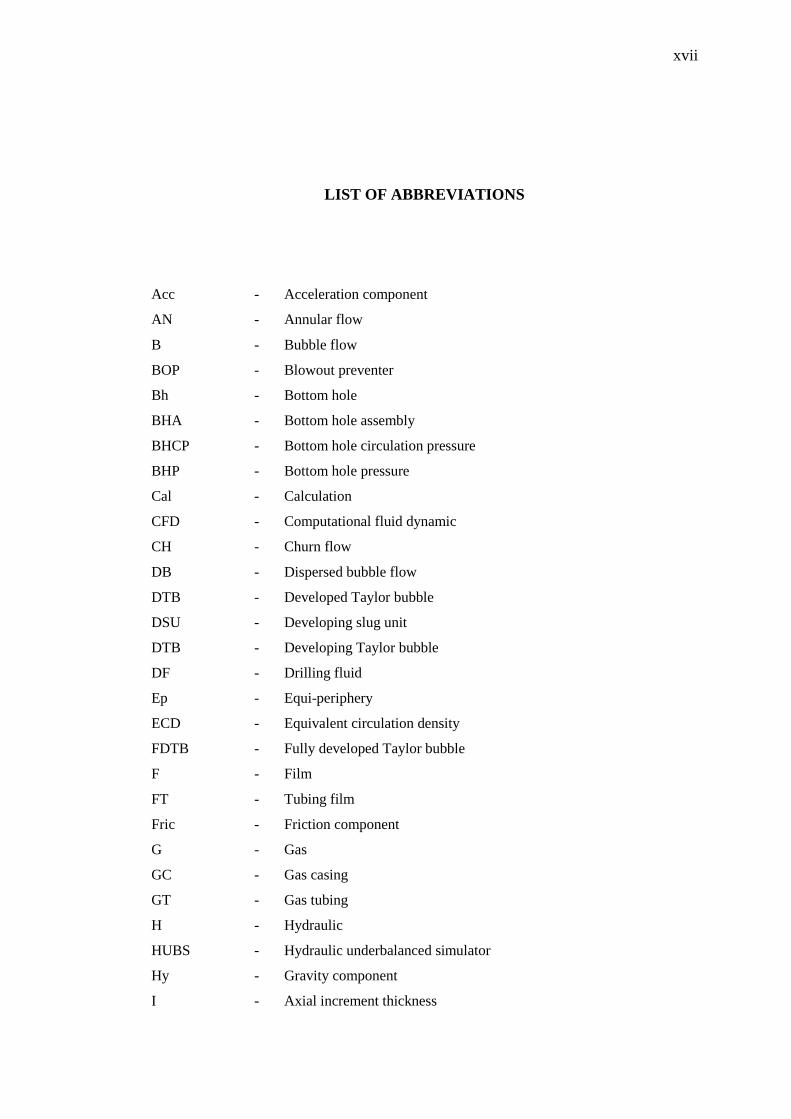
xvii
LIST OF ABBREVIATIONS
Acc - Acceleration component
AN - Annular flow
B - Bubble flow
BOP - Blowout preventer
Bh - Bottom hole
BHA - Bottom hole assembly
BHCP - Bottom hole circulation pressure
BHP - Bottom hole pressure
Cal - Calculation
CFD - Computational fluid dynamic
CH - Churn flow
DB - Dispersed bubble flow
DTB - Developed Taylor bubble
DSU - Developing slug unit
DTB - Developing Taylor bubble
DF - Drilling fluid
Ep - Equi-periphery
ECD - Equivalent circulation density
FDTB - Fully developed Taylor bubble
F - Film
FT - Tubing film
Fric - Friction component
G - Gas
GC - Gas casing
GT - Gas tubing
H - Hydraulic
HUBS - Hydraulic underbalanced simulator
Hy - Gravity component
I - Axial increment thickness
Page 17
xviii
IC - In situ condition or inner casing
IT - Inner tubing
L - Liquid
LS - Liquid slug
LC - Liquid holdup in gas core
LF - Liquid film
LFC - Casing liquid film holdup
LFT - Tubing liquid film holdup
LS - Slug liquid holdup
LSC - Slug liquid holdup corresponding to casing liquid film
MPD - Managed pressure drilling
N - Nozzle
N - Nitrogen
NG - Natural gas
OBD - Overbalanced drilling
OT - Outer tubing
ODE - Ordinary differential equation
P - Pipe
R - Radius, m
R - Reservoir
RBOP - Rotating blowout preventer
RCH - Rotating control head
ROP - Rate of penetration
S - Surface
S - Slug flow
Sc - Standard condition
SG - Superficial gas
SL - Superficial liquid
SU - Slug unit
T - Total or translational
TB - Taylor bubble
Up - Upstream
UBD - Underbalanced drilling
W - Water or wall
Wp - Wellbore pressure
Page 18
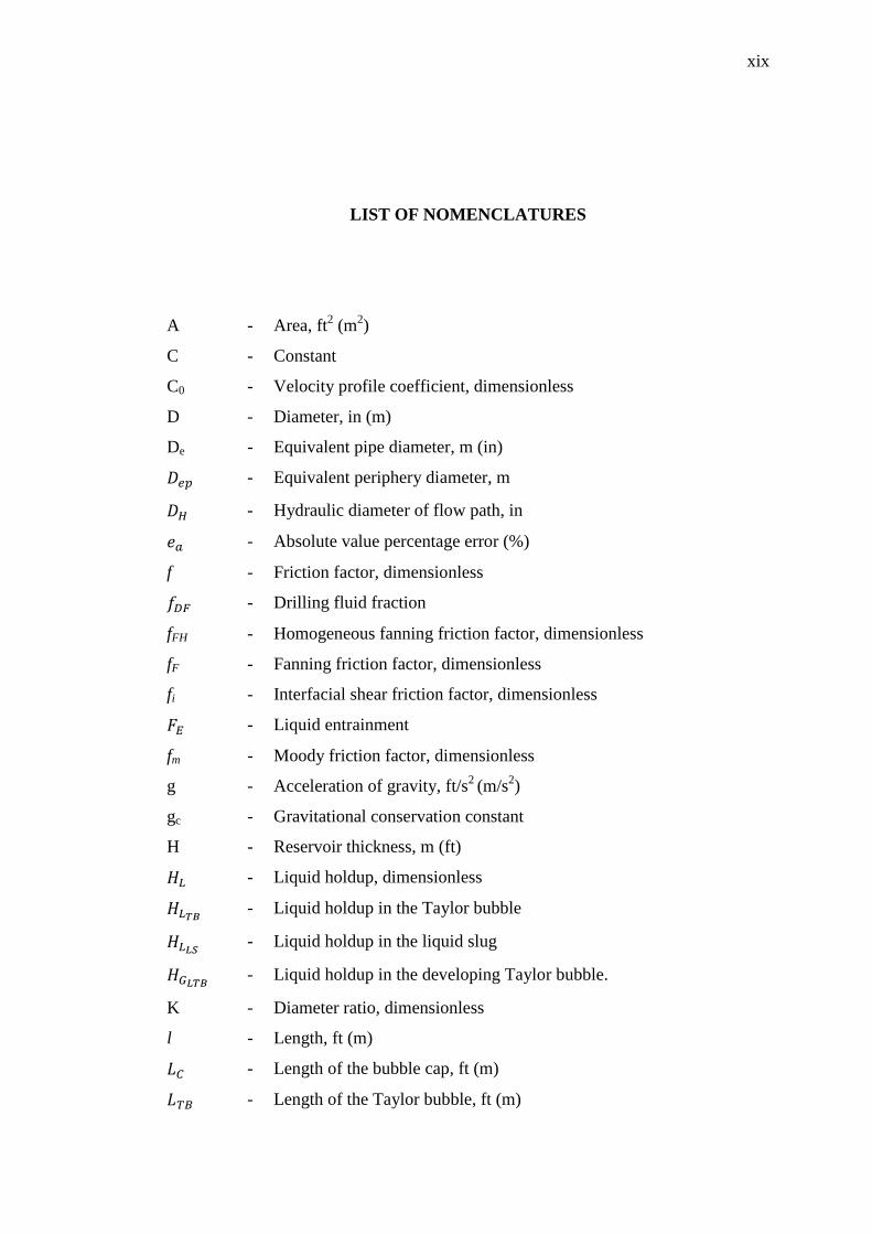
xix
LIST OF NOMENCLATURES
A - Area, ft2 (m
2)
C - Constant
C0 - Velocity profile coefficient, dimensionless
D - Diameter, in (m)
De - Equivalent pipe diameter, m (in)
- Equivalent periphery diameter, m
- Hydraulic diameter of flow path, in
- Absolute value percentage error (%)
f - Friction factor, dimensionless
- Drilling fluid fraction
fFH - Homogeneous fanning friction factor, dimensionless
fF - Fanning friction factor, dimensionless
fi - Interfacial shear friction factor, dimensionless
- Liquid entrainment
fm - Moody friction factor, dimensionless
g - Acceleration of gravity, ft/s2
(m/s2)
gc - Gravitational conservation constant
H - Reservoir thickness, m (ft)
- Liquid holdup, dimensionless
- Liquid holdup in the Taylor bubble
- Liquid holdup in the liquid slug
- Liquid holdup in the developing Taylor bubble.
K - Diameter ratio, dimensionless
l - Length, ft (m)
- Length of the bubble cap, ft (m)
- Length of the Taylor bubble, ft (m)
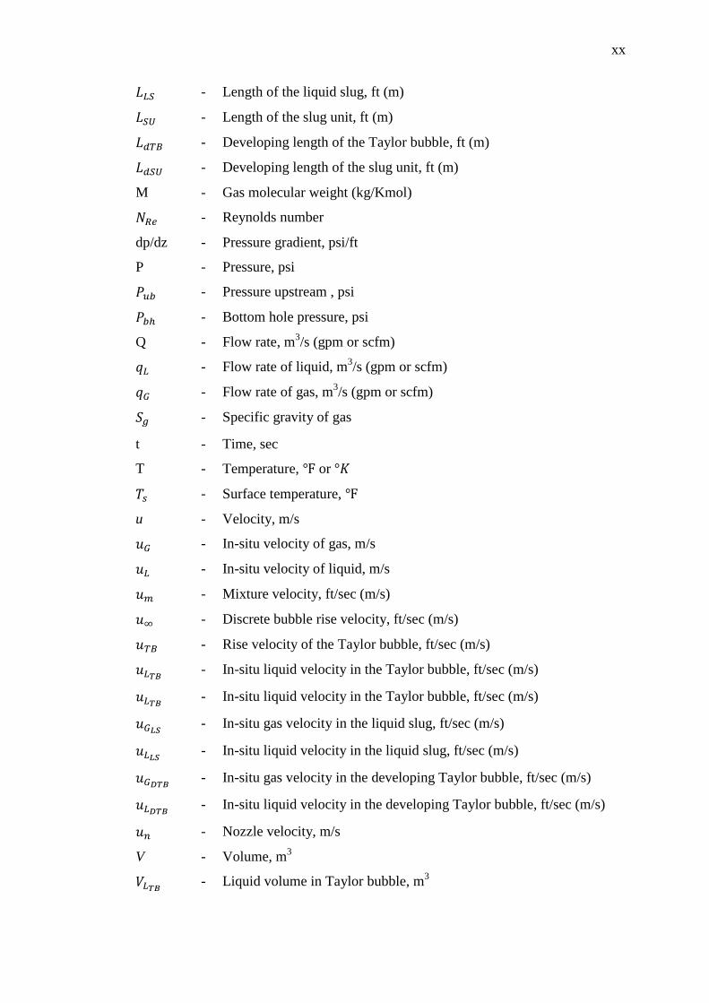
Page 19
xx
- Length of the liquid slug, ft (m)
- Length of the slug unit, ft (m)
- Developing length of the Taylor bubble, ft (m)
- Developing length of the slug unit, ft (m)
M - Gas molecular weight (kg/Kmol)
- Reynolds number
dp/dz - Pressure gradient, psi/ft
P - Pressure, psi
- Pressure upstream , psi
- Bottom hole pressure, psi
Q - Flow rate, m3/s (gpm or scfm)
- Flow rate of liquid, m3/s (gpm or scfm)
- Flow rate of gas, m3/s (gpm or scfm)
- Specific gravity of gas
t - Time, sec
T - Temperature, or
- Surface temperature,
u - Velocity, m/s
- In-situ velocity of gas, m/s
- In-situ velocity of liquid, m/s
- Mixture velocity, ft/sec (m/s)
- Discrete bubble rise velocity, ft/sec (m/s)
- Rise velocity of the Taylor bubble, ft/sec (m/s)
- In-situ liquid velocity in the Taylor bubble, ft/sec (m/s)
- In-situ liquid velocity in the Taylor bubble, ft/sec (m/s)
- In-situ gas velocity in the liquid slug, ft/sec (m/s)
- In-situ liquid velocity in the liquid slug, ft/sec (m/s)
- In-situ gas velocity in the developing Taylor bubble, ft/sec (m/s)
- In-situ liquid velocity in the developing Taylor bubble, ft/sec (m/s)
- Nozzle velocity, m/s
V - Volume, m3
- Liquid volume in Taylor bubble, m3
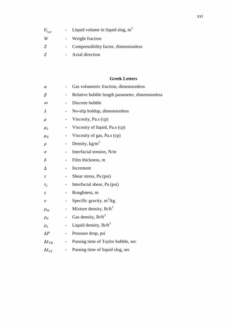
Page 20
xxi
- Liquid volume in liquid slug, m3
W - Weight fraction
Z - Compressibility factor, dimensionless
Z - Axial direction
Greek Letters
- Gas volumetric fraction, dimensionless
- Relative bubble length parameter, dimensionless
- Discrete bubble
- No-slip holdup, dimensionless
- Viscosity, Pa.s (cp)
- Viscosity of liquid, Pa.s (cp)
- Viscosity of gas, Pa.s (cp)
- Density, kg/m3
- Interfacial tension, N/m
- Film thickness, m
- Increment
- Shear stress, Pa (psi)
- Interfacial shear, Pa (psi)
- Roughness, m
- Specific gravity, m3/kg
- Mixture density, lb/ft3
- Gas density, lb/ft3
- Liquid density, lb/ft3
- Pressure drop, psi
- Passing time of Taylor bubble, sec
- Passing time of liquid slug, sec
Page 21
xxii
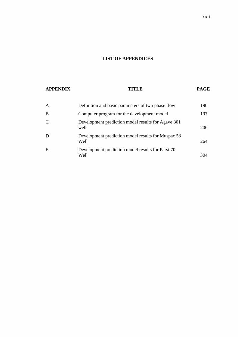
LIST OF APPENDICES
APPENDIX TITLE PAGE
A Definition and basic parameters of two phase flow 190
B Computer program for the development model 197
C Development prediction model results for Agave 301
well
206
D Development prediction model results for Muspac 53
Well
264
E Development prediction model results for Parsi 70
Well
304
Page 22
CHAPTER 1
INTRODUCTION
1.1 Background of Study
Underbalanced drilling method is determined as drilling process in which the
pressure of wellbore is lower than the formation pressure in the open hole section.
The UBD system is designed to operate with pressure of wellbore below the pressure
of formation. The pressure underbalanced connote that if porous and permeable
formations are exposed, the reservoir fluids will enter the wellbore while drilling. In
overbalanced drilling operation well control is influenced by using a hydrostatic
pressure higher than the formation pressure. In UBD, this differential is eliminated
and wellbore pressure is kept less the formation pressure. Thus, there is a concept of
well control condition during the UBD technology. The benefits of UBD technique
encompass the followings: less differential sticking, improve penetration rate, reduce
formation damage, and early production.
When there are equipment failures, mismanaging of drilling fluids, poor
reservoir selection, and human mistake then underbalanced drilling method failed.
The underbalanced drilling technology is gaining in amicability as drilling method to
dominate some of the problems faced in overbalanced drilling. Underbalanced
drilling method is adopted for solving drilling problems and it also can minimize
formation damage. UBD technology has improvement of oil and gas formations that
otherwise would not be exploited due to the technical and economic limitations. It is
also a tool both for formation performance development and formation
Page 23
2
characterization as well as for remarking drilling problems. Underbalanced drilling
operation is considered to be more expensive than conventional drilling. Even though
UBD technique is more expensive than conventional drilling, it has some advantages
over the conventional drilling technology. Some of these advantages include early
production of hydrocarbons and quick recovery of cost expended on it (UBD
technique).
Generally, decrease of the hydrostatic pressure in the annular decreases the
fluid losses into a reservoir formation. In underbalanced drilling operation, the
bottom hole pressure must be deliberately below the pressure of formation, therefore,
the fluid losses do not appear there during drilling underbalanced. Due to the lack of
overburden on the reservoir formation and the absence of any filter cake, the drill
string will be prevented from differential sticking while drilling underbalanced. The
reduction of the overpressure over the pressure of formation has a considerable effect
on the rate of penetration. It also has an affirmative impact on the bit life due to the
less weight on the drilling bit.
The applications of UBD technique comprise the followings: aerated liquid,
stable foam, and gas or air drilling. When liquid is combined with air/gas drilling, the
drilling fluid becomes mist or unstable foam. The limitations of UBD technology
comprise the followings: liquid influx problems, wellbore stability, safety and
economic problems, and directional drilling problems. In some formations, when the
wellbore is not stable, the underbalanced drilling cannot be used because it is not
economically feasible. The surface equipment requirements of underbalanced drilling
technology encompass the following: downstream choke-manifold system, wellhead
rotating control device, upstream gas generation systems, geologic sampler, and
open/close fluid handling systems. When the formation is exceedingly depleted, an
upstream gas generation would be required.
During UBD operation in which the formation pressure is greater than
hydrostatic pressure of fluids in wellbore may make a condition such as a kick. So,
controlling and predicting the pressures and maintain assured environment need
Page 24
3
specific surface pressure control equipment and a group of crew who are
satisfactorily educated. The kind of necessary items relies on mainly the lithology,
permeabilities, and formation pressures. In under balanced drilling technique, a
complex fluid system appears in the drill-string and the annulus. In underbalanced
drilling operation, the well bore pressure control is obtained by conducting the well
returns through surface choke pressure.
Production of formation fluids during UBD are separated by separation tanks
at the well head. Therefore, the regular rotary rig must be adjusted for under
balanced drilling operation with some significant adjustment. Controlling the flow
pressure at the bottom-hole is the key parameter in the success of the UBD operation.
If the BHP becomes greater than the formation pressure, the UBD changes to over-
balanced drilling (OBD) and if the BHP becomes too lower than the formation
pressure this may lead to kicking of the well or may cause the wall well collapse.
Therefore, the bottom-hole pressure should be kept in a specific pressure limits
known as pressure window. Keeping BHP in the window limits is more difficult than
the over-balanced drilling because a specific ratio of two fluids (gas and liquid)
should be continuously injected in the well to reach the desired BHP which depends
mainly on the formation pressure and the choke pressure.
1.2 Problem Statement
The emergence of UBD technology can be used to avoid complicated drilling
problems, such as reservoir damage and circulation loss. The success of a UBD
operation is subdominant of the ability to keep up underbalanced situations during
the whole drilling operation and this underbalanced pressure condition is needed to
be maintained by bottom-hole pressure control according to specific operating
conditions and actual status of fluid in wellbore. In underbalanced drilling operations
with regular rigs, drilling fluids are pumped down through the drill-string, getting
through the bit nozzle, and then going up in the annular space. In the annular, drilling
fluids are mixed with drilling cuttings and formation fluids. Therefore,
Page 25
4
underbalanced hydraulic circulating system is typically determined by two or more
phases. When a pipe moves up and down along the axis of a wellbore filled with a
nonmoving fluid, friction pressure losses are induced. The main concern in friction
pressure losses due to pipe movement is related to the annulus section. During pipe
connection operation in UBD, the mud circulation system has to be stopped.
Therefore, bottom hole pressure decreases at the beginning due to the losses
frictional pressure. The stop of mud circulation causes the disruption of steady state
conditions. Due to buoyancy and inertial forces the gas phases moves upward and the
liquid phases flow downward.
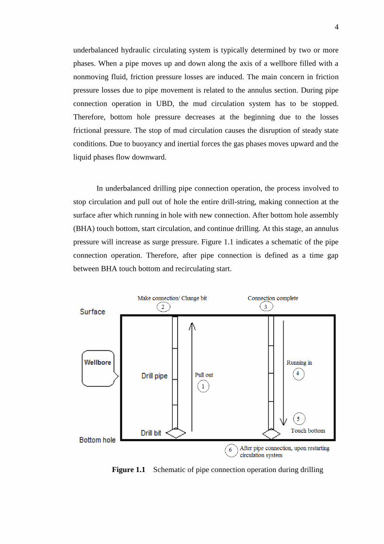
In underbalanced drilling pipe connection operation, the process involved to
stop circulation and pull out of hole the entire drill-string, making connection at the
surface after which running in hole with new connection. After bottom hole assembly
(BHA) touch bottom, start circulation, and continue drilling. At this stage, an annulus
pressure will increase as surge pressure. Figure 1.1 indicates a schematic of the pipe
connection operation. Therefore, after pipe connection is defined as a time gap
between BHA touch bottom and recirculating start.
Figure 1.1 Schematic of pipe connection operation during drilling
Page 26
5
After pipe connection operation in UBD, upon restarting mud circulation
system, frictional pressure influenced the BHP and the fluid slugs in the drill-string
are transferred into the annular space. Therefore, the hydrostatic pressure will be
increasing. Since this event occurs after pipe connection operation, and the period
between drilling and pipe connection is inadequate to obtain steady situations again,
underbalanced drilling pipe connection operations create a bottom hole pressure
vibration. If the bottom hole pressure vibration is not properly maintained below the
pressure of formation, the reservoir formation will lead to an OBD condition after
pipe connection operation. Consequently, after pipe connection in UBD a pressure
spike is observed with a short period of sustaining higher BHP that usually exposes
the formation to overbalanced conditions. This particular time can reduce the
benefits obtained to drill the well underbalanced. Therefore, the foundation of UBD
analysis and study is to establish mechanistic steady state two phase flow model to
predict wellbore pressure. As shown in Figure 1.2 the BHP vibrations recorded after
pipe connection operation upon restarting circulation system in underbalanced
drilling operation. It’s also shown that changing a choke pressure setting may also
cause severe vibrations in the BHP.
After pipe connection
Figure 1.2 Typical BHP vibration after pipe connection in UBD (Guo and Liu,
2011).
Page 27
6
The key factor for a successful UBD operation is to achieve the objectives
through maintaining underbalanced drilling condition. In order to achieve such
success, the bottom hole pressure should be maintained within a pressure window
that is bounded below by the formation pore pressure and above the wellbore
stability pressure or surface facilities restrictions. Hence, the prediction of wellbore
pressure should be as accurate as possible in order to assist in designing equipment
needed to UBD operations. Recently, development of mechanistic models has
allowed accurate prediction of wellbore pressure. Mechanistic models are based on
the physical phenomena of the complex fluid system and flow rather than the use of
empirical correlations, which are based mainly on experimental data.
Therefore, it seems that one should use better mechanistic steady state model
for two phase flow in which a set of partial differential equations are used to describe
the physics of the flow. This research is the study in which the mechanistic steady
state two-phase flow through the annulus, bit nozzles, and drill-string is used to
simulate flow behavior in the UBD operation. Two phase flow patterns in the
annulus and drill-string, wellbore pressure predictions, gas/liquid superficial
velocities in the wellbore, liquid and gas holdup, two phase flow pattern maps,
wellbore temperatures, and minimum gas volume requirement in the wellbore are
presented accordingly. The performance of the development model is validating with
field data and previous works. In this steady state two phase flow model
development, two phases are considered as the two interpenetrating continua. Steady
state two phase flow model development has a high potential for the analysis of two-
phase flows and has extensively been used in modeling different two-phase flow.
1.3 Research Objective
In this study, the main objective is to predict BHP after pipe connection
operation in UBD in which mud circulation system restarts. The details of objective
encompass the followings:
Page 28
7
i. To develop mechanistic steady state model for two phase flow through
the annulus and drill-string.
ii. To predict BHP after pipe connection operation in UBD.
iii. To review two phase flow patterns in UBD operation.
iv. To analyze the effect of the choke pressure and gas/liquid flow rate on the
BHP.
1.4 Scope of Study
In this study, the bottom hole pressure prediction is based on the outcomes of
a mechanistic steady state model development by developing analytical equations
using fundamental laws of physics and mathematics to predict the wellbore pressure
and BHP, the flow behavior, flow patterns and their transitional boundaries for two
phase flow (gas-liquid) through drill-sting, bit nozzle and in the annular space. In
flowing, effects of gas/liquid flow rate recharges and also choke pressures change on
pressure and flow patterns are defined. Then this model equation, based on drift flux
model is defined and computer program by means of Fortran 95 will be developed.
The following simplifications have been adopted in order to establish flow model in
UBD: (i)·It is a steady state model and can only simulate an established situation; (ii)
The drilled cuttings are transported at the same velocity in the annulus as the liquid
phase; (iii) The cross section of the wellbore is circular and concentric with drill-
string; (iv) The gas resolution in drilling fluid is negligible and there is no chemical
reaction; (v) The ·gas and liquid medium is in thermodynamics balanced status, and
pressure and density is single valued function; (vi) No fluid production from
reservoirs are considered.
1.5 Significance of Study
Previous steady state gas-liquid two-phase models in UBD operations fall
into three categories. The first is the steady state computer programs that neglect slip
Page 29
8
between phases by assuming that aerated mud can be treated as a homogeneous
mixture. The second is the steady state computer programs that used empirical
correlations to take into account slip between phases and predict different flow
patterns. The third is the steady state computer programs based on mechanistic
models rather than empirical correlations to take into account slip between phases
and predict different flow patterns. Most studies on UBD models focused on the first
and the second types of models in the recent years. Validations show that lowers
prediction accuracy than the accuracy needed in practical operations. The
mechanistic approach postulates the existence of different flow configurations and
formulates separate models for each one of these flow patterns to predict the main
parameters, such as gas fraction, two phase flow patterns, and wellbore pressure.
Consequently, mechanistic steady state two phase flow models, rather than empirical
correlations, have been used with increasing frequency for the design of multiphase
wellbore pressure system. But, the previous studies did not use mechanistic models
to reach good accuracy of wellbore pressure and two phase flow parameters in the
annulus and drill-string during underbalanced drilling operation. Therefore, there is a
need to predict wellbore pressure in the annulus and drill-string during
underbalanced drilling operation using mechanistic steady state two phase flow
model. This research is the study in which the mechanistic steady state two phase
flow model is used to predict wellbore pressure in the annulus and drill-string in the
underbalanced drilling operation. Furthermore, two phase flow patterns, flow pattern
maps, void fraction, wellbore temperature, and minimum gas volume requirement in
the annulus and drill-string are presented. In addition, the effects on bottom-hole
pressure of different back pressures at the wellhead, gas and liquid injection flow rate
are simulated and analysed. The flow patterns used in the research include five types:
bubble flow, dispersed bubble flow, churn flow, annular flow, and slug flow
according to the configurations of two phase flow in the wellbore. Computational
methods for gas void fraction and pressure drop are presented in each flow pattern
respectively.
Page 30
REFERENCES
Al-Ajmi, A. M., & Zimmerman, R. W. (2006). Stability Analysis of Vertical
Boreholes Using the Mogi–Coulomb Failure Criterion. International Journal of
Rock Mechanics and Mining Sciences. 43(8), 1200–1211.
ALAdwani, F. A. (2003). Mechanistic Modeling of an Underbalanced Drilling
Operation Utilizing Supercritical Carbon Dioxide. Kuwait University.
Al-Safran, E., Owayed, J. F., Al-Bazali, T., & Sunthankar, A. (2008). Optimization
of Required Volumetric Flow Rates for Aerated Mud Underbalanced Drilling.
Petroleum Science and Technology. 26(12), 1403–1423.
Ashena, R., Moghadasi, J., Ashena, R., Roshanai, F., Sarmadivaleh, M., & Safian, G.
(2010). Mechanistic Modeling of Annular Two-Phase Flow While
Underbalanced Drilling in Iran. In Nigeria Annual International Conference and
Exhibition. January. Nigeria: Society of Petroleum Engineers.
Ashena, R., & Moghadasi, J. (2011). Bottomhole Pressure Estimation Using Evolved
Neural Networks by Real Coded ant Colony Optimization and Genetic
Algorithm. Journal of Petroleum Science and Engineering. 77(3-4), 375–385.
Azar, J. J., & Samuel, G. R. (2007). Drilling Engineering. PennWell Books.
Azzopardi, B. J., & Wren, E. (2004). What is Entrainment in Vertical Two-phase
Churn Flow?. International Journal of Multiphase Flow. 30(1), 89-103.
Azzopardi, B., & Hills, J. (2003a). One Dimensional Models for Pressure Drop,
Empirical Equations for Void Fraction and Frictional Pressure Prop and
Pressure Drop and Other Effects in Fittings. Springer Vienna.
Azzopardi, B. J. (2006). Gas-Liquid Flows. New York: Begell House. 6- 40.
Azzopardi, B., & Hills, J. (2003b). Flow Patterns, Transitions and Models for
Specific Flow Patterns. Springer Vienna.
Page 31
182
Azzopardi, B., Zhao, D., Yan, Y., Morvan, H., Mudde, R. F., & Lo, S. (2011).
Hydrodynamics of Gas-liquid Reactors: Normal Operation and Upset
Conditions. John Wiley & Sons.
Azzopardi, B. J. (2008). Flow patterns: Does Gas/Solids Flow Pattern Correspond to
Churn Flow in Gas/Liquid Flow. Industrial & Engineering Chemistry Research.
47(20), 7934-7939.
Bratland, O. (2010). Pipe Flow 2, Multiphase Flow Assurance. 41 - 39.
Brauner, N., & Ullmann, A. (2002). Modeling of Phase Inversion Phenomenon in
Two-phase Pipe Flows. International Journal of Multiphase Flow. 28(7), 1177-
1204.
Brauner, N., & Ullmann, A. (2004). Modelling of Gas Entrainment from Taylor
bubbles. Part A: Slug flow. International Journal of Multiphase Flow. 30(3),
239-272.
Celata, G. P. (2008). Single-and Two-phase Flow Heat Transfer in Micropipes.
In Fifth European Thermal-Sciences Conference. Eindhoven, the Netherlands.
Celata, G. P., Lorenzini, M., Morini, G. L., & Zummo, G. (2009). Friction Factor in
Micropipe Gas Flow Under Laminar, Transition and Turbulent Flow Regime.
International Journal of Heat and Fluid Flow. 30(5), 814-822.
Cheng, H., Hills, J. H., & Azzopardi, B. J. (2002). Effects of Initial Bubble Size on
Flow Pattern Transition in a 28.9 mm Diameter Column. International Journal
of Multiphase Flow. 28(6), 1047-1062.
Cheng, R. C., Wang, H. G., Ge, Y. H., Cui, M., Drilling, C., & Ma, G. Z. (2010).
SPE 131844 New Development and Application of Underbalanced Drilling
Technology in China : A Critical Review UBD Application Status of CNPC.
Chung, P. Y., & Kawaji, M. (2004). The Effect of Channel Diameter on Adiabatic
Two-phase Flow Characteristics in Microchannels. International Journal of
Multiphase Flow. 30(7), 735-761.
Church, O. S., & Road, B. (2002). Introduction to Underbalanced Drilling. 1–51.
Coddington, P., & Macian, R. (2002). A Study of the Performance of Void Fraction
Correlations Used in the Context of Drift-Flux Two-Phase Flow Models.
Nuclear Engineering and Design, 215(3), 199-216.
Das, A. K. (2007). Simulation Study Evaluating Alternative Initial responses to
Formation Fluid Influx During Managed Pressure Drilling. Open University.
Page 32
183
Dorenbos, R., & Ranalho, J. (2002). Underbalanced Drilling Primer. Shell
International Exploration and Production BV.
El Hajal, J., Thome, J. R., & Cavallini, A. (2003). Condensation in Horizontal Tubes,
Part 1: Two-phase Flow Pattern Map. International Journal of Heat and Mass
Transfer. 46(18), 3349-3363.
Fattah, K. A., El-Katatney, S. M., & Dahab, A. A. (2011). Potential Implementation
of Underbalanced Drilling Technique in Egyptian Oil Fields. Journal of King
Saud University - Engineering Sciences, 23(1), 49–66.
Feili Monfared, A., Ranjbar, M., Nezamabadi-Poor, H., Schaffie, M., & Ashena, R.
(2011). Development of a Neural Fuzzy System for Advanced Prediction of
Bottomhole Circulating Pressure in Underbalanced Drilling Operations.
Petroleum Science and Technology. 29(21), 2282–2292.
Finley, D., Ansah, J., Gil, I., Lovorn, R., Shayegi, S., & Services, H. E. (2007).
IADC / SPE 108350 Comparisons of Reservoir Knowledge , Drilling Benefits ,
and Economic Advantages for Underbalanced and Managed-Pressure Drilling.
Gao, B., Guo, C., Hou, X., Yang, C., Zeng, Y., & Zhang, J. (2007). Automatic
Control System and Method for Bottomhole Pressure in the Underbalance
Drilling. Patent and Trademark Office.
Goda, H., Hibiki, T., Kim, S., Ishii, M., & Uhle, J. (2003). Drift-Flux Model for
Downward Two-Phase Flow. International Journal of Heat and Mass Transfer,
46(25), 4835-4844.
Groth, C., & Zingg, D. W. (2006). Computational Fluid Dynamics. Proceedings of
the Third International Conference on Computational Fluid Dynamics,
ICCFD3, Toronto. 12-16 July 2004. Springer.
Guang-xin, Z. Y. C. W., Yu-fang, Z. H. J. J., & Lu-cai, T. I. A. N. (2003).
Application of Underbalanced Drilling Technology in Weishen-5Well of
Daqing Oilfield. Acta Petrolei Sinica, 6(21).
Guet, S., Ooms, G., & Oliemans, R. V. A. (2002). Influence of Bubble Size on the
Transition From Low-Re Bubbly Flow to Slug Flow in a Vertical Pipe.
Experimental Thermal and Fluid Science. 26(6), 635-641.
Guo, B., & Ghalambor, A. (2002). An Innovation in Designing Underbalanced
Drilling Flow Rates: A Gas-Liquid Rate Window (GLRW) Approach.
IADC/SPE Asia Pacific Drilling Technology.
Page 33
184
Guo, B., Lyons, W.C., & Ghalambor, A. (2011). Petroleum Production Engineering,
A Computer-Assisted Approach. Amsterdam: Gulf Professional Publishing.
Guo, B., & Liu, G. (2011). Applied Drilling Circulation Systems Hydraulics,
Calculations and Models. Amsterdam: Gulf Professional Publishing. 4- 6.
Guo, W., Honghai, F., & Gang, L. (2011). Design and Calculation of a MPD Model
with Constant Bottomhole Pressure. Petroleum Exploration and Development,
38(1), 103–108.
Hasan, A. R., Kabir, C. S., & Sarica, C. (2002). Fluid Flow and Heat Transfer in
Wellbores. Society of Petroleum Engineers.
Hibiki, T., & Ishii, M. (2002). Distribution Parameter and Drift Velocity of Drift-
Flux Model in Bubbly Flow. International Journal of Heat and Mass
Transfer, 45(4), 707-721.
Hooshmandkoochi, A., Zaferanieh, M., & Malekzadeh, A. (2007). First Application
of Underbalanced Drilling in Fractured Carbonate Formations of Iranian
Oilfields Leads to Operational Success and Cost Savings. In SPE Middle East
Oil and Gas Show and Conference. Society of Petroleum Engineers.
Hong, W. P., TENG, F. Y., & LIU, Y. (2013). Analysis of Complexity and Chaos
Morphological Characteristics of Gas-Liquid Flow's Differential Pressure
Fluctuation Signal across Tube Bundles. Control and Instruments in Chemical
Industry. 2, 021.
Irani, R., & Nasimi, R. (2011). Application of Artificial Bee Colony-Based Neural
Network in Bottomhole Pressure Prediction in Underbalanced Drilling. Journal
of Petroleum Science and Engineering. 78(1), 6–12.
Ismail, I., Misnan, S., Ismail, A. S. I., & Mohsin, R. (2014, July). Flow Pattern Map
of Malaysian Crude Oil and Water Two-Phase Flow in a Pipe System. In
Advanced Materials Research. 931. 1243-1247.
Ismail, A. S. I., Ismail, I., Zoveidavianpoor, M., Mohsin, R., Piroozian, A., Misnan,
M. S., & Sariman, M. Z. (2015). Experimental Investigation of Oil–Water Two-
Phase Flow in Horizontal Pipes: Pressure Losses, Liquid Holdup and Flow
Patterns. Journal of Petroleum Science and Engineering, 127, 409-420.
Johnson, R. L., Montilva, J. C., Sati, M. F., Grable, J. L., Saeed, S., Billa, R. J., &
Derise, B. (2011). Field Demonstration of a New Method for Making Drill-Pipe
Connections during Managed-Pressure Drilling Operations. SPE147278.
Page 34
185
Kabir, M., Saloussy, E., Al-sabea, S., Ambastha, A., & Qutob, H. (2008). OTC
19313 Kuwait Oil Company Employs a Systematic Approach to Ensure
Successful Underbalanced Drilling Project : A Case Study.
Kawahara, A., Chung, P. Y., & Kawaji, M. (2002). Investigation of Two-phase Flow
Pattern, Void Fraction and Pressure Drop in a Microchannel. International
Journal of Multiphase Flow. 28(9), 1411-1435.
Kawahara, A., Sadatomi, M., Okayama, K., Kawaji, M., & Chung, P. Y. (2005).
Effects of Channel Diameter and Liquid Properties on Void Fraction in
Adiabatic Two-phase Flow Through Microchannels. Heat Transfer
Engineering. 26(3), 13-19.
Kaya, A. S., Sarica, C., & Brill, J. P. (2001). Mechanistic Modeling of Two-Phase
Flow in Deviated Wells. SPE Production & Facilities. 16(03), 156-165.
Krepper, E., Lucas, D., & Prasser, H. M. (2005). On the Modelling of Bubbly Flow
in Vertical Pipes. Nuclear Engineering and Design. 235(5), 597-611.
Khezrian, M., Hajidavalloo, E., & Shekari, Y. (2014). Modeling and Simulation of
Under-balanced Drilling Operation Using Two-Fluid Model of Two-Phase
Flow. Chemical Engineering Research and Design, 1–8.
Lage, A.C.V.M., Time, R. . (2002). An Expermental and Theoretical Investigation of
Upward Two-Phase Flow in Annuli. SPE64525.
Lage, A. C. V. M., Rommetveit, R., & Time, R. W. (2000). An Experimental and
Theoretical Study of Two-Phase Flow in Horizontal or Slightly Deviated Fully
Eccentric annuli. IADC/SPE Asia Pacific Drilling Technology. 11- 13
September, Kuala Lumpur, Malaysia.
Lage, A.C.V.M., Time, R. (2000). Mechanistic Model for Upward Two-Phase Flow
in Annuli. SPE63127.
Lange, V., Azzopardi, B. J., & Licence, P. (2013). Hydrodynamics of Ionic Liquids
in Bubble Columns.
Lapeyrouse, N. J. (2002). Formulas and Calculations for Drilling, Production, and
Workover. Gulf Professional Publishing.
Li, J., Luft, B. H., Wilde, G., Alingig, G., & Jumawid, F. (2008). Cleanouts with
Coiled Tubing in Low-Bottomhole-Pressure Wellbores. In SPE/ICoTA Coiled
Tubing and Well Intervention Conference and Exhibition. Society of Petroleum
Engineers. 1- 2 April, the Woodlands, Texas, USA.
Page 35
186
Liu, G., Hu, Z., Li, J., & Tao, Q. (2009). Bottomhole Pressure Control Method in
Pressure-Control Drilling. Oil Drilling & Production Technology. 2(006).
Lyons, W. C. (2009). Air and Gas Drilling Manual: Applications for Oil and Gas
Recovery Wells and Geothermal Fluids Recovery Wells. Gulf Professional
Publishing.
Metin, C. O., & Ozbayoglu, M. E. (2007). Analysis of Two-Phase Fluid Flow
Through Fully Eccentric Horizontal Annuli. British Hydromechanics Research
(BHR) Group. In 13th
International Conference on Multhiphase Production
Technology, 13- 15 June, Edinburgh, UK.
Nygaard, G. H., Vefring, E. H., Fjelde, K. K., Nævdal, G., Lorentzen, R. J., &
Mylvaganam, S. (2004). Bottomhole Pressure Control During Pipe Connection
in Gas-Dominant Wells. In SPE/IADC Underbalanced Technology Conference
and Exhibition. Society of Petroleum Engineers. 11- 12 October, Houston,
Texas.
Omebere-Iyari, N. K., Azzopardi, B. J., Lucas, D., Beyer, M., & Prasser, H. M.
(2008). The Characteristics of Gas/Liquid Flow in Large Risers at High
Pressures. International Journal of Multiphase Flow. 34(5), 461-476.
Osgouei, R. E., Ozbayoglu, M. E., Ozbayoglu, a. M. (2012). A Mechannistic Model
to Characterize the Two Phase Drilling Fluid Flow through Inclined Eccentric
Annular Geometry. SPE155147.
Ostroot, K., Shayegi, S., Lewis, D., Lovorn, R., & Services, H. E. (2007). OTC
18561 Comparison and Advantages of Underbalanced and Managed-Pressure
Drilling Techniques : When Should Each Be Applied ?
Ozbayoglu, M. E., & Ozbayoglu, M. A. (2007). Flow pattern and frictional-pressure-
loss estimation using neural networks for UBD operations. In IADC/SPE
Managed Pressure Drilling & Underbalanced Operations.
Paasche, M., Johansen, T. A., & Imsland, L. (2011). Regularized and Adaptive
Nonlinear Moving Horizon Estimation of Bottomhole Pressure during Oil Well
Drilling.
Perez-Tellez, C. (2003). Improved Bottom-hole Pressure Control for Underbalanced
Drilling Operations. Louisiana State University.
Perez-tellez, C. Smith, J. R, Edvards, J. K. (2003). A New Comprehensive
Mechanistic Model for Underbalanced Drilling Improves Wellbore Pressure
Predictions. SPE74426.
Page 36
187
Prasser, H. M., Scholz, D., & Zippe, C. (2001). Bubble Size Measurement Using
Wire-Mesh Sensors. Flow Measurement and Instrumentation. 12(4), 299-312.
Qutob, H. H., & Ferreira, H. (2005). The SURE Way to Underbalanced Drilling. In
In SPE Middle East Oil and Gas Show and Conference. Society of Petroleum
Engineers.
Rehm, B., Haghshenas, A., Paknejad, A. S., Al-Yami, A., & Hughes, J. (2013).
Underbalanced Drilling: Limits and Extremes. Elsevier.
Sawai, T., Kaji, M., Kasugai, T., Nakashima, H., & Mori, T. (2004). Gas–liquid
Interfacial Structure and Pressure Drop Characteristics of Churn Flow.
Experimental Thermal and Fluid Science. 28(6), 597-606.
Serizawa, A., & Feng, Z. (2000). Review of Two-Phase Flow in Microchannels.
In Proceedings of the US–Japan Seminar on Two-Phase Flow Dynamics, june
Santa Barbara, California, US.
Serizawa, A., Feng, Z., & Kawara, Z. (2002). Two-phase Flow in Microchannels.
Experimental Thermal and Fluid Science. 26(6), 703-714.
Shadravan, A., Nabaei, M., Yrc, O. B., & Amani, M. (2009a). Dealing with the
Challenges of UBD Implementation in Southern Iranian Oilfields. In the Middle
East Drilling Technology Conference & Exhabition. 26-28 October. Manama,
Bahrain (3), 1–10.
Shadravan, A. (2009). Dealing with the Challenges of UBD Implemenation in
Southern Iranian Oilfield. Bchelor Degree, Islamic Azad University, Omidieh
Btanch, Iran.
Shadravan, A., Nabaei, M., & Amani, M. (2009b). Development of Underbalanced
Drilling Implementation in Parsi Oilfield. In Offshore Europe Oil & Gas
Conference & Exhibition. 8-11 September. Aberdeen, UK.
Shadravan, A., Khodadadian, M. Shahbazi, K. and Roohi, A. (2009c).
Underbalanced Drilling Technology, the Key for Solving Drilling Problems. In
the First International Petroleum Conference & Exhibition. 4-6 May. Shiraz,
Iran.
Sheu, G. R., Lin, N. H., Wang, J. L., Lee, C. T., Ou Yang, C. F., & Wang, S. H.
(2010). Temporal Distribution and Potential Sources of Atmospheric Mercury
Measured at a High-Elevation Background Station in Taiwan. Atmospheric
Environment. 44(20), 2393-2400.
Page 37
188
Shirkavand, F., Hareland, G., & Olson, W. (2010). The Design and Development of
a Drilling Simulator for Planning and Optimizing Under-Balanced Drilling
Operations. Journal of Canadian Petroleum Technology. 49(6), 68-73.
Shoham, O. (2006). Mechanistic Modeling of Gas–liquid Two-phase Flow in Pipes.
Society of Petroleum Engineers. pipes, 222 Published Creek Drive Richardson,
TX 75080- 2040, USA.
Sorgun, M., Osgouei, R. E., Ozbayoglu, M. E., & Ozbayoglu, a. M. (2013). An
Experimental and Numerical Study of Two-phase Flow in Horizontal Eccentric
Annuli. Energy Sources, Part A: Recovery, Utilization, and Environmental
Effects. 35(10), 891–899.
Sui, D., Nybø, R., Giulio, G., Davide, R., & Mario, H. (2012). A Moving Horizon
Observer for Estimation of Bottomhole Pressure During Drilling. Automatic
Control in Offshore Oil and Gas Production.
Tabatabai, A., & Faghri, A. (2001). A New Two-phase Flow Map and Transition
Boundary Accounting for Surface Tension Effects in Horizontal Miniature and
Micro Tubes. Journal of Heat Transfer. 123(5), 958-968.
Thome, J. R., & Hajal, J. E. (2003). Two-phase Flow Pattern Map for Evaporation in
Horizontal Tubes, latest version. Heat Tansfer Engineering. 24(6), 3-10.
Thome, J. R., El Hajal, J., & Cavallini, A. (2003). Condensation in horizontal tubes,
part 2: New Heat Transfer Model Based on Flow Regimes. International
Journal of Heat and Mass Transfer, 46(18), 3365-3387.
Tzotzi, C., Bontozoglou, V., Andritsos, N., & Vlachogiannis, M. (2010). Effect of
Fluid Properties on Flow Patterns in Two-Phase Gas− Liquid Flow in
Horizontal and Downward Pipes†. Industrial & Engineering Chemistry
Research, 50(2), 645-655.
WELLFLO Software. (2011). 8th
.ed. Scandpower Petroleum Technology (SPT)
Group.
Williams, M., Lewis, D., & Bernard, C. J. (2003). A Safe Approach to Drilling
Underbalanced Starts with Project Management. In SPE/IADC Middle East
Drilling Technology Conference and Exhibition. Society of Petroleum
Engineers.
Xu, J., Shen, S., Gan, Y., Li, Y., Zhang, W., & Su, Q. (2005). Transient Flow Pattern
Based Microscale Boiling Heat Transfer Mechanisms. Journal of
Micromechanics and Microengineering. 15(6), 1344.
Page 38
189
Yingcao, Z., Deli, G., Hongjun, Z., & Guangxin, W. (2004). Application of
Underbalanced Drilling Technology in Exploratory Wells of Daqing. Oil
Drilling & Production Technology. 4, 000.
Yu, T. T., Zhang, H., Li, M. X., & Sarica, C. (2010). A Mechanistic Model for Gas /
Liquid Flow in Upward Vertical Annuli, October, 4–7.
Zhang, H. Q., Wang, Q., Sarica, C., & Brill, J. P. (2003a). Unified Model for Gas-
Liquid Pipe Flow via Slug Dynamics part 1: model development. Journal of
Energy Resources Technology. 125(4), 266-273.
Zhang, H. Q., Wang, Q., Sarica, C., & Brill, J. P. (2003b). A Unified Mechanistic
Model for Slug Liquid Holdup and Transition Between Slug and Dispersed
Bubble Flows. International Journal of Multiphase Flow. 29(1), 97-107.
Zhao, K., Scherer, P. W., Hajiloo, S. A., & Dalton, P. (2004). Effect of Anatomy on
Human Nasal Air Flow and Odorant Transport Patterns, Implications for
Olfaction. Chemical Senses. 29(5), 365-379.