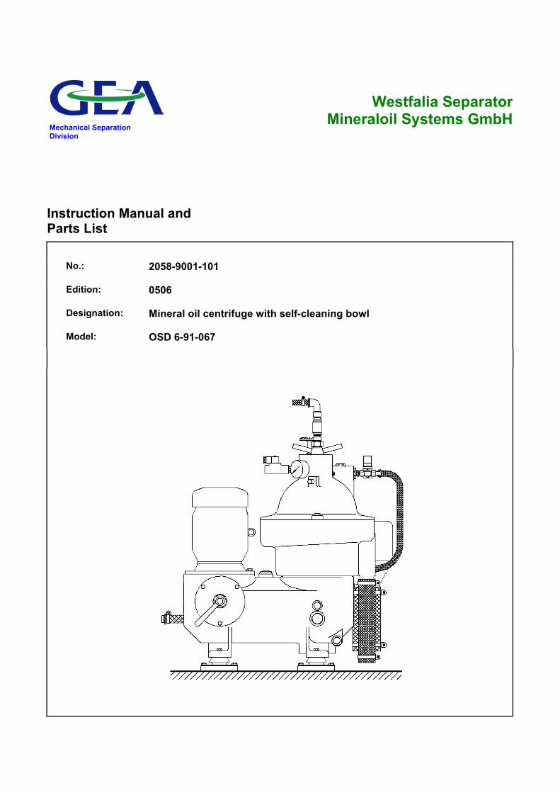
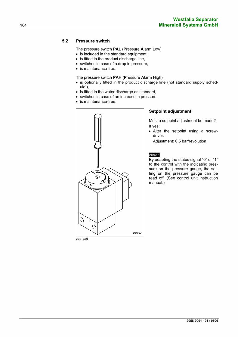
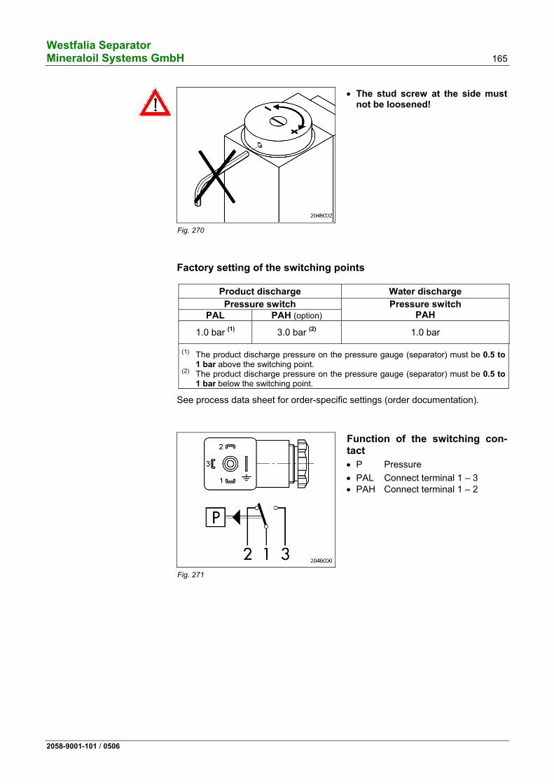
Mechanical Separation Division Westfalia Separator Mineraloil Systems GmbH Instruction Manual and Parts List No.: 2058-9001-101 Edition: 0506 Designation: Mineral oil centrifuge with self-cleaning bowl Model: OSD 6-91-067
Transcript
Mechanical Separation Division
Westfalia Separator Mineraloil Systems GmbH
Instruction Manual and Parts List
No.: 2058-9001-101
Edition: 0506
Designation: Mineral oil centrifuge with self-cleaning bowl
Model: OSD 6-91-067
Westfalia Separator 2 Mineraloil Systems GmbH
2058-9001-101 / 0506
Subject to modification! The authors are always grateful for comments and suggestions for improving the documentation. They can be sent to
GEA Westfalia Separator Mineraloil Systems GmbH Werner-Habig-Str. 1 D-59302 Oelde
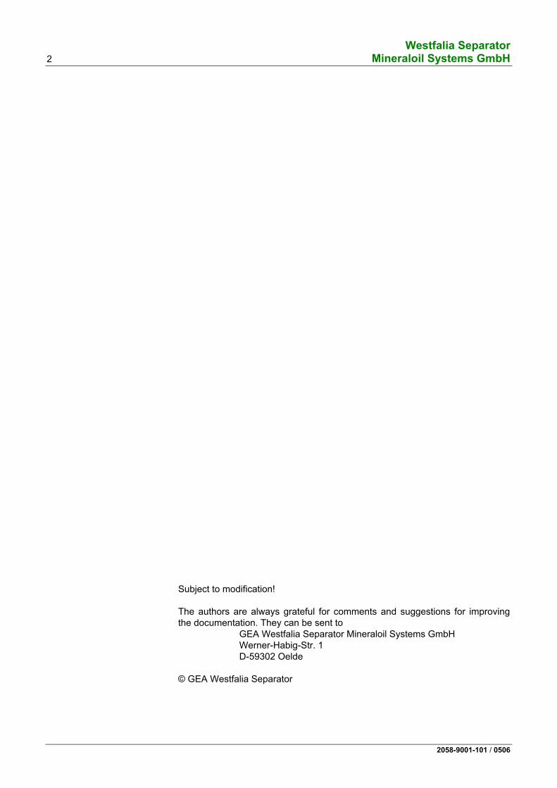
This nameplate must be filled in by the operator. Please transfer the data from the centrifuge nameplate.
Westfalia Separator 4 Mineraloil Systems GmbH
2058-9001-101 / 0506
For your safety
• Strictly adhere to instructions marked with this symbol.
This avoids damage to the separator and other equipment.
• Take special care when carrying out operations marked with this symbol -
otherwise danger to life.
Note: • This symbol is not a safety precaution but rather a reference to infor-mation which help to better understand the separator or plant compo-nents and the processes.
• Observe the accident prevention regulations!
The local safety and accident prevention regulations apply uncondi-tionally to the operation of the separator. The plant operator must en-sure compliance with these regulations.
• Follow the instructions in the manual.
Follow only the instructions given in this manual. Repair and maintenance work that goes beyond the scope described in this manual may not be carried out.
• Operate the separator only in accordance with agreed process and operating parameters
• Maintain the separator
as specified in this manual. • Carry out safety checks on the separator,
as described in chapter "Safety precautions" in this manual
• Liability for the function of the machine passes to the owner.
Liability for the function of the machine passes unconditionally to the owner or operator irrespective of existing warranty periods in so far as the machine is improperly maintained or serviced by persons other than Westfalia Separator service personnel or if the machine is not applied in accordance with the intended use.
Westfalia Separator shall not be liable for damage which occurs as a result of non-observance of the above. Warranty and liability condi-tions in the Conditions of Sale and Delivery of Westfalia Separator are not extended by the above.
Westfalia Separator Mineraloil Systems GmbH 5
2058-9001-101 / 0506
1 Safety precautions 9
1.1 Correct usage ........................................................................................10 1.2 Safety markings .....................................................................................10 1.2.1 Safety markings and their meaning .......................................................11 1.3 Basic operating principles......................................................................14 1.4 Bowl speed and product ........................................................................14 1.5 Demands relating to service personnel and spare parts .......................15 1.6 Operations on the separator ..................................................................16 1.6.1 Assembly ...............................................................................................16 1.6.2 Electrical appliances ..............................................................................18 1.6.3 Before start-up .......................................................................................18 1.6.4 Starting...................................................................................................21 1.6.5 Shut-down and »Emergency-Off« .........................................................23 1.6.6 Maintenance and repair .........................................................................24 1.7 Corrosion ...............................................................................................27 1.8 Erosion...................................................................................................28 1.9 The health hazards involved when handling heavy oils and lube oils...30 1.9.1 Code of practice and personal protective measures .............................30
2 Machine description 31
2.1 Dimensioned drawing of the separator..................................................32 2.2 Section through separator .....................................................................34 2.3 General ..................................................................................................35 2.4 OSD ...-91-… .........................................................................................35 2.5 Main components of the separator ........................................................38 2.5.1 Bowl .......................................................................................................39 2.5.2 Bowl hydraulic system ...........................................................................40 2.5.3 Centripetal pump ...................................................................................43 2.5.4 Sensing liquid pump ..............................................................................44 2.5.5 Drive.......................................................................................................45 2.6 The regulating ring.................................................................................46 2.6.1 Determining the size of the regulating ring with the aid of the diagram..................................................................................................46 2.6.2 Determining the regulating ring by experiment......................................48 2.7 Technical data .......................................................................................50
3 Operation 53
3.1 Technical information.............................................................................54 3.1.1 Notes on separation...............................................................................54 3.1.2 General information on bowl ejection ....................................................54 3.2 Before start-up .......................................................................................56 3.2.1 Before the first start-up ..........................................................................56 3.2.2 Before every start-up .............................................................................56 3.3 Starting the separator ............................................................................57 3.4 Monitoring of operation..........................................................................57 3.5 Setting the separation time....................................................................58 3.5.1 Mathematical calculation .......................................................................58 3.6 Ejecting the bowl....................................................................................59 3.7 Shutting down the separator..................................................................60 3.8 Trouble shooting ....................................................................................62
4.1 Installation of the separator ...............................................................72 4.1.1 Transporting the separator ....................................................................74 4.1.2 Installing the separator ..........................................................................75 4.1.3 Motor......................................................................................................76 4.1.4 Direction of rotation of the bowl .............................................................77 4.1.5 Speed and starting time of the bowl ......................................................78 4.2 Maintenance and lubrication..................................................................80 4.2.1 Maintenance schedule...........................................................................80 4.2.2 Hoses and hose pipes ...........................................................................83 4.2.3 Lubrication .............................................................................................84 4.2.4 Lubrication Chart ...................................................................................86 4.2.5 Table of lubricating oils ..........................................................................88 4.2.6 Comments on table of lubricating oils for separators from Westfalia
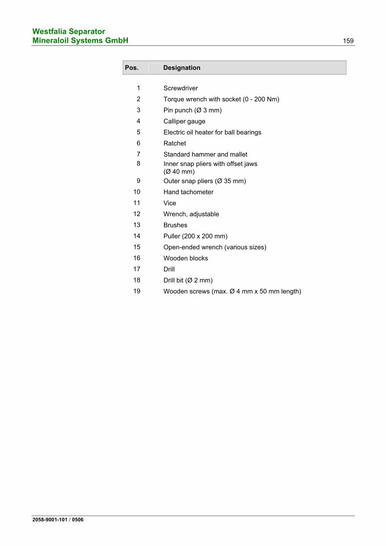
Separator ...............................................................................................89 4.3 Bowl .......................................................................................................90 4.3.1 Dismantling the bowl..............................................................................92 4.3.2 Cleaning the bowl ................................................................................102 4.3.3 Cleaning the frame ..............................................................................103 4.3.4 Cleaning the strainer and the operating water feeding system ...........103 4.3.5 Important instructions ..........................................................................104 4.3.6 Assembling the bowl............................................................................106 4.3.7 Replacing the polyamide gasket in the annular piston ........................119 4.3.8 Replacing the polyamide gasket (bowl top).........................................121 4.3.9 Reworking the sliding piston................................................................123 4.4 Closing the hood..................................................................................125 4.5 Motor and centrifugal clutch ................................................................127 4.6 Drive.....................................................................................................128 4.6.1 Important instructions ..........................................................................130 4.6.2 Removing the drive belt and spindle assembly ...................................132 4.6.3 Dismantling the spindle assembly .......................................................136 4.6.4 Removing the centrifugal clutch ..........................................................138 4.6.5 Fitting the spindle assembly ................................................................142 4.6.6 Fitting the centrifugal clutch.................................................................144 4.6.7 Fitting the motor...................................................................................149 4.7 Height adjustment................................................................................152 4.7.1 Bowl height ..........................................................................................152 4.7.2 Centripetal pump clearance.................................................................153 4.8 Final checks after assembling the separator .......................................155 4.9 Before a long-term shut-down of the separator ...................................155 4.10 Before restarting ..................................................................................156 4.11 Standard tools......................................................................................158
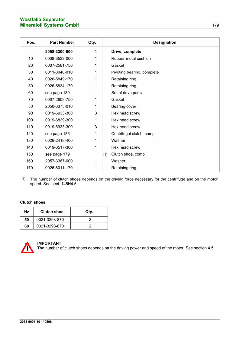
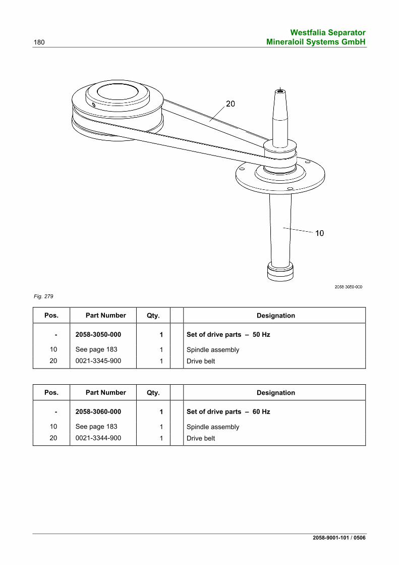
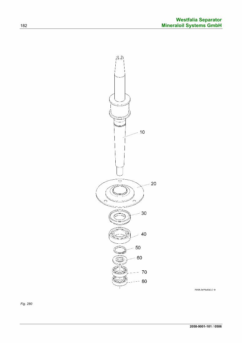
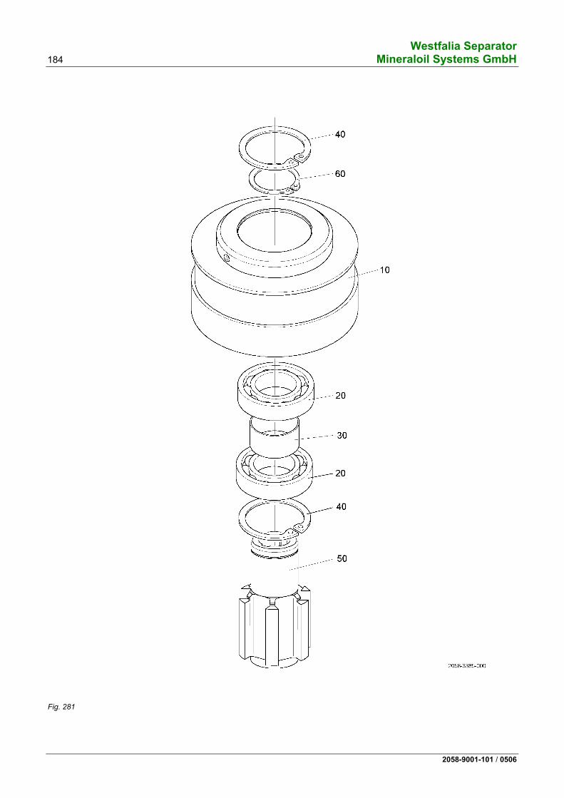
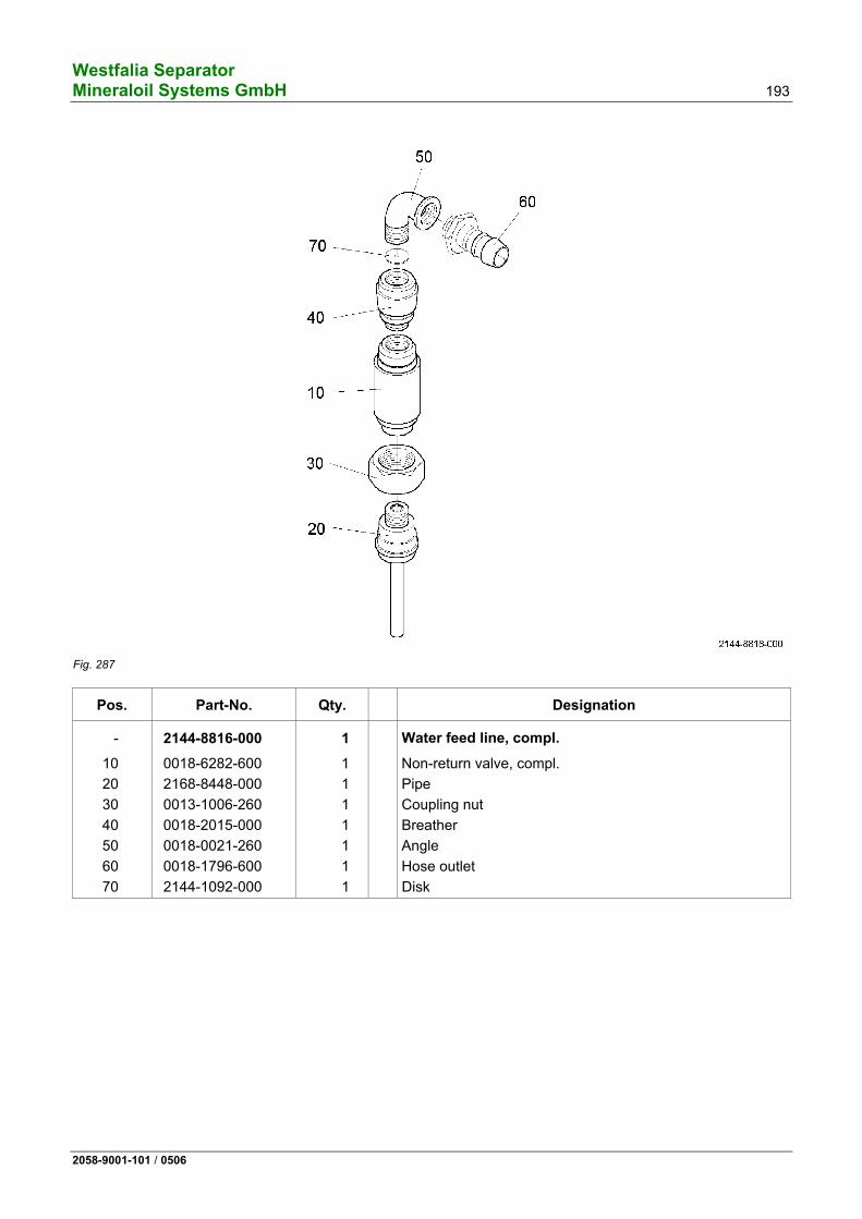
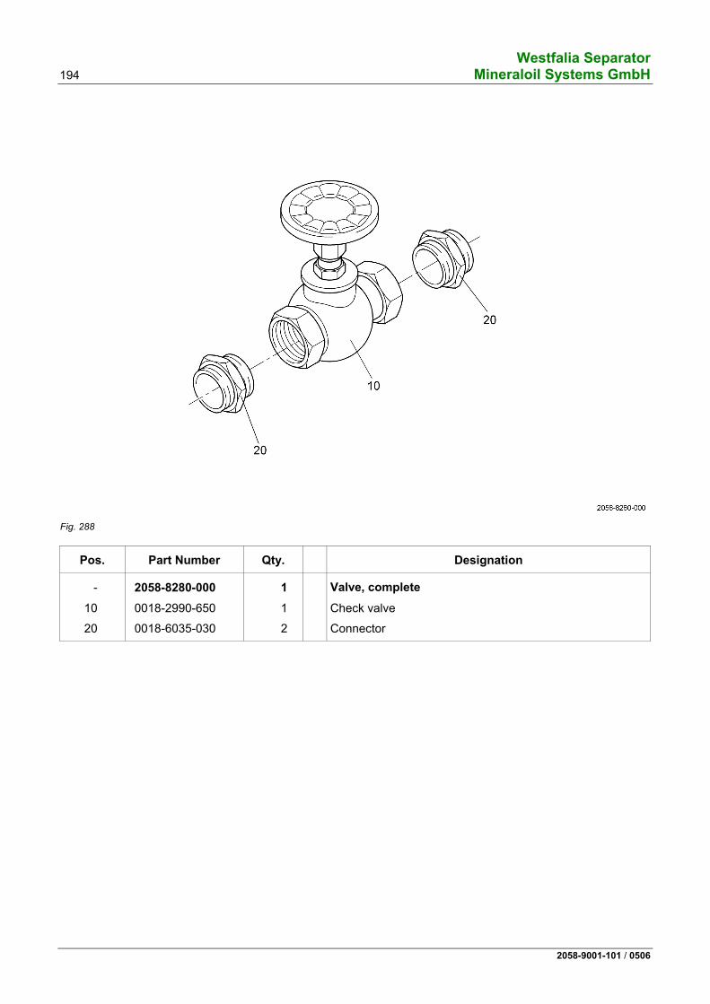
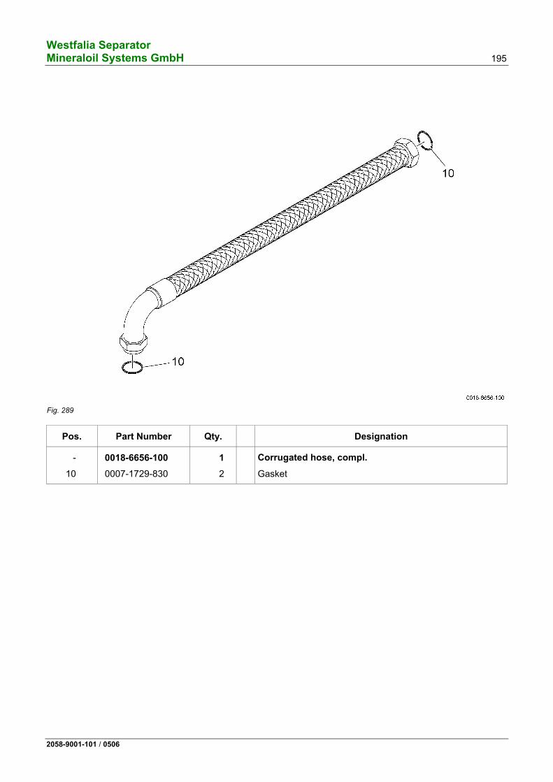
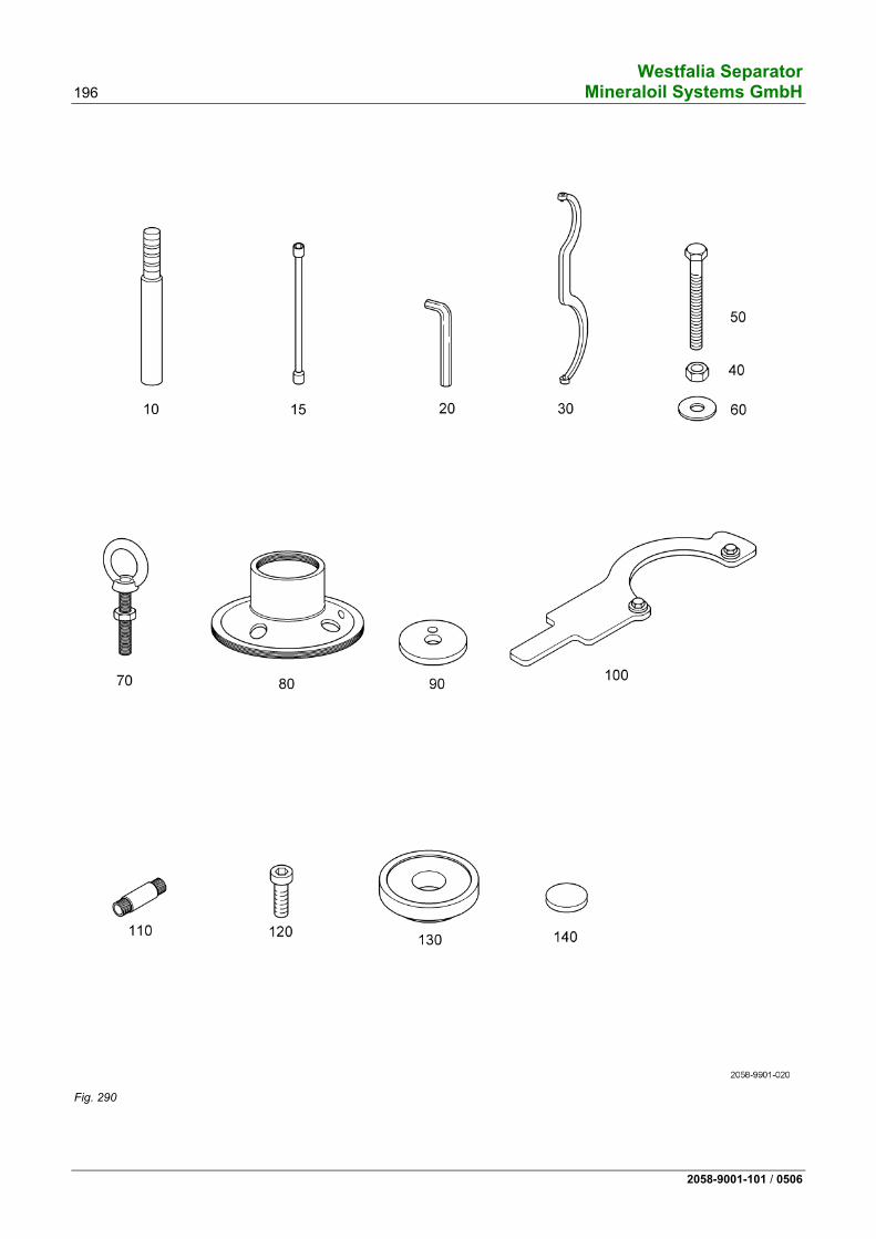
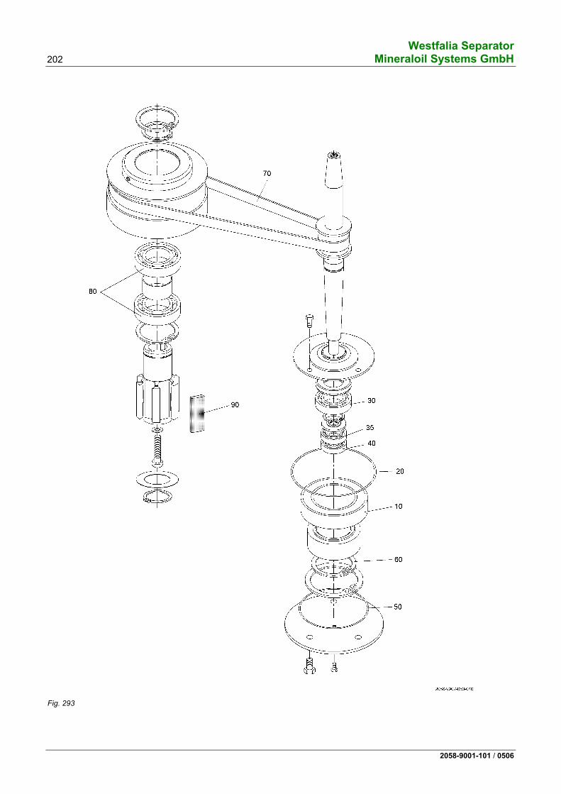
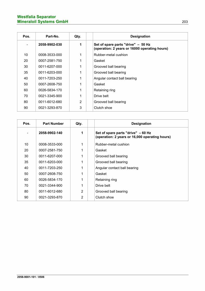
Guide to ordering spare parts......................................................................169 Set of plates......................................................................................................171 Frame, compl....................................................................................................173 Brake bolt, complete.........................................................................................174 Solenoid valve block, complete ........................................................................175 Solenoid valve block, compl. ............................................................................176 Drive, complete.................................................................................................179 Clutch shoes.....................................................................................................179 Set of drive parts – 50 Hz...............................................................................180 Set of drive parts – 60 Hz...............................................................................180 Spindle, complete - 50 Hz ..............................................................................183 Spindle, complete - 60 Hz ..............................................................................183 Centrifugal clutch, complete .............................................................................185 Bowl, complete .................................................................................................187 Disk stack, complete ........................................................................................188 Centripetal pump, compl. .................................................................................189 Hood, complete ................................................................................................191 Retaining bracket, compl..................................................................................192 Water feed line, compl......................................................................................193 Valve, complete ................................................................................................194 Corrugated hose, compl. ..................................................................................195 Set of tools and accessories ............................................................................197 Lubricants (hazardous materials!) ....................................................................197 Set of spare parts "bowl/hood“ (operation: 1 year or 8000 hours) ..................199 Set of spare parts "drive" – 50 Hz (operation: 1 year or 8000 hours) ............201 Set of spare parts "drive" – 60 Hz (operation: 1 year or 8000 hours) ............201 Set of spare parts "drive" – 50 Hz (operation: 2 years or 16000 operating hours).................................................203 Set of spare parts "drive" – 60 Hz (operation: 2 years or 16,000 operating hours)................................................203
11111111111111111111111111
Westfalia Separator 8 Mineraloil Systems GmbH
2058-9001-101 / 0506
Westfalia Separator Mineraloil Systems GmbH 9
2058-9001-101 / 0506
1 Safety precautions
1.1 Correct usage ........................................................................................10 1.2 Safety markings .....................................................................................10 1.2.1 Safety markings and their meaning .......................................................11 1.3 Basic operating principles......................................................................14 1.4 Bowl speed and product ........................................................................14 1.5 Demands relating to service personnel and spare parts .......................15 1.6 Operations on the separator ..................................................................16 1.6.1 Assembly ...............................................................................................16 1.6.2 Electrical appliances ..............................................................................18 1.6.3 Before start-up .......................................................................................18 1.6.4 Starting...................................................................................................21 1.6.5 Shut-down and »Emergency-Off« .........................................................23 1.6.6 Maintenance and repair .........................................................................24 1.7 Corrosion ...............................................................................................27 1.8 Erosion...................................................................................................28 1.9 The health hazards involved when handling heavy oils and lube oils...30 1.9.1 Code of practice and personal protective measures .............................30
Westfalia Separator 10 Mineraloil Systems GmbH
2058-9001-101 / 0506
1.1 Correct usage The separator is designed
• in accordance with the chemical and physical properties of the product speci-fied by the customer and
• in accordance with the method of application of the separator agreed with Westfalia Separator.
In particular, products not conforming to the specifications on the nameplate may not be used.
Any mode of operation deviating herefrom is not proper and correct.
Prior to any intended deviation from the agreed operating mode, it is therefore imperative to obtain the consent of Westfalia Separator.
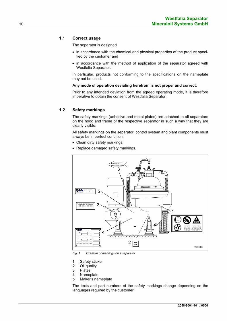
1.2 Safety markings The safety markings (adhesive and metal plates) are attached to all separators on the hood and frame of the respective separator in such a way that they are clearly visible.
All safety markings on the separator, control system and plant components must always be in perfect condition. • Clean dirty safety markings. • Replace damaged safety markings.
The texts and part numbers of the safety markings change depending on the languages required by the customer.
Westfalia Separator Mineraloil Systems GmbH 11
2058-9001-101 / 0506
1.2.1 Safety markings and their meaning
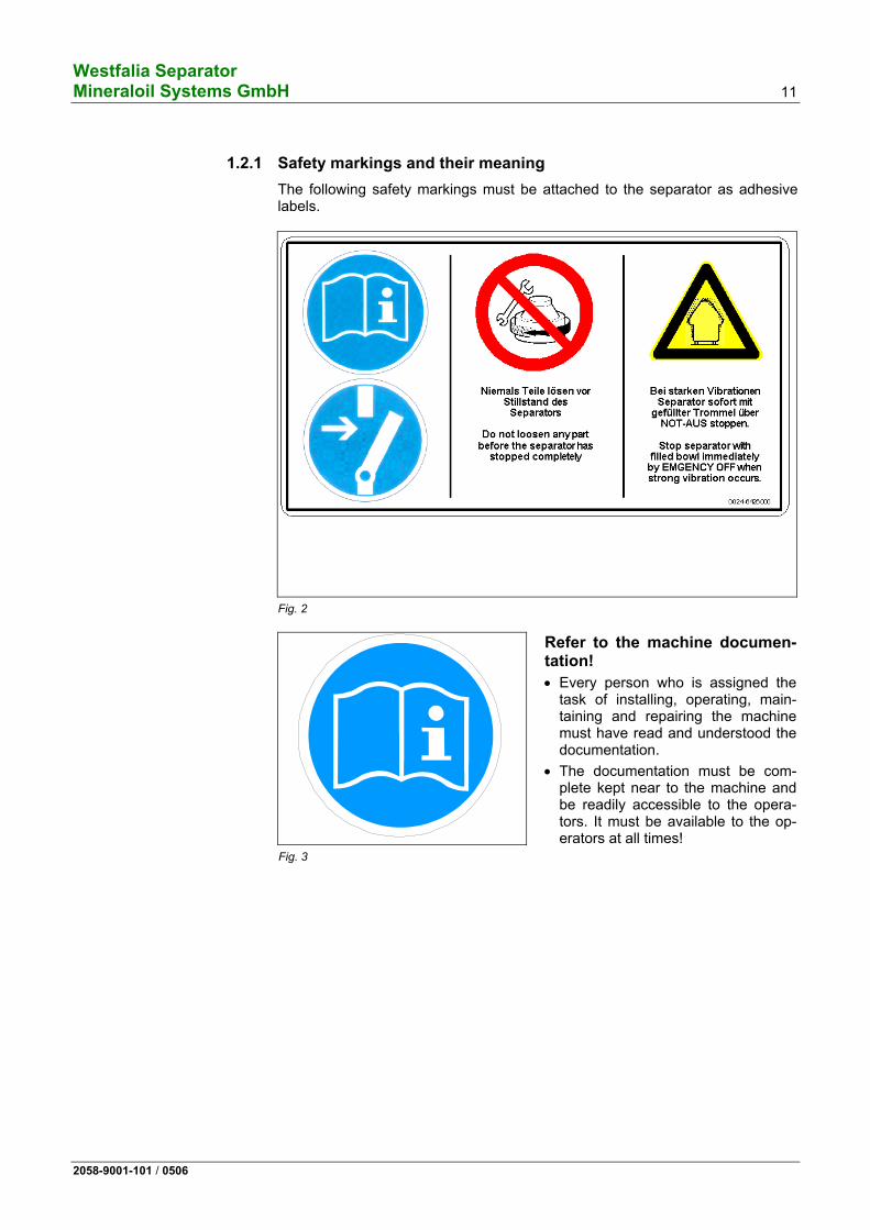
The following safety markings must be attached to the separator as adhesive labels.
Fig. 2
Fig. 3
Refer to the machine documen-tation!
• Every person who is assigned the task of installing, operating, main-taining and repairing the machine must have read and understood the documentation.
• The documentation must be com-plete kept near to the machine and be readily accessible to the opera-tors. It must be available to the op-erators at all times!
Westfalia Separator 12 Mineraloil Systems GmbH
2058-9001-101 / 0506
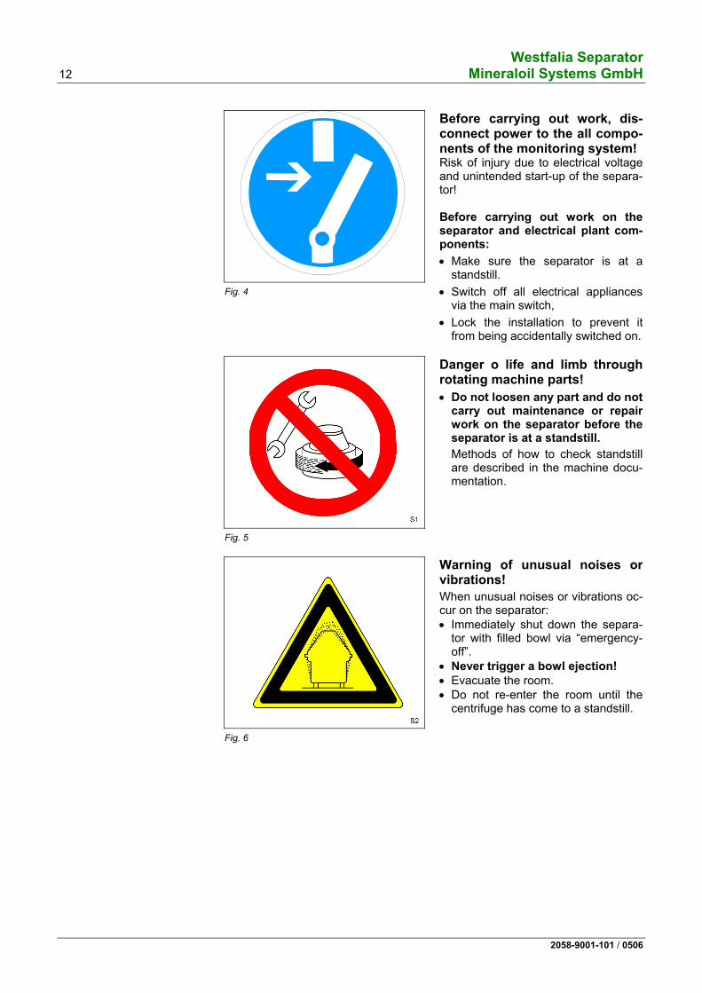
Fig. 4
Before carrying out work, dis-connect power to the all compo-nents of the monitoring system!Risk of injury due to electrical voltage and unintended start-up of the separa-tor! Before carrying out work on the separator and electrical plant com-ponents:
• Make sure the separator is at a standstill.
• Switch off all electrical appliances via the main switch,
• Lock the installation to prevent it from being accidentally switched on.
Fig. 5
Danger o life and limb through rotating machine parts!
• Do not loosen any part and do not carry out maintenance or repair work on the separator before the separator is at a standstill.
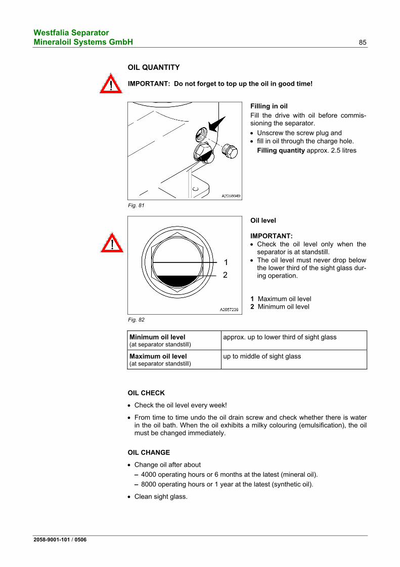
Methods of how to check standstill are described in the machine docu-mentation.
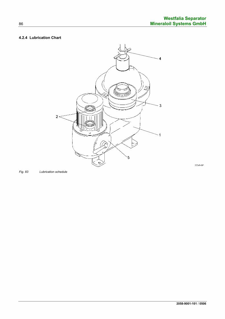
Fig. 6
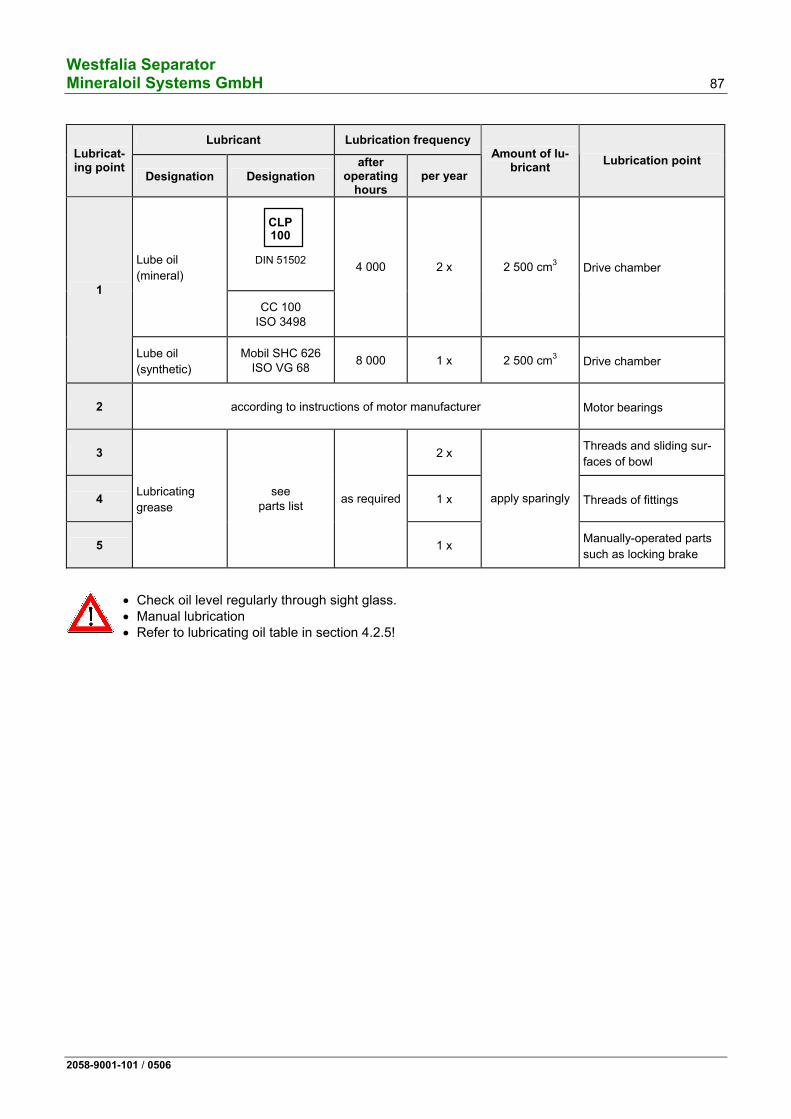
Warning of unusual noises or vibrations!
When unusual noises or vibrations oc-cur on the separator: • Immediately shut down the separa-
tor with filled bowl via “emergency-off”.
• Never trigger a bowl ejection! • Evacuate the room. • Do not re-enter the room until the
centrifuge has come to a standstill.
Westfalia Separator Mineraloil Systems GmbH 13
2058-9001-101 / 0506
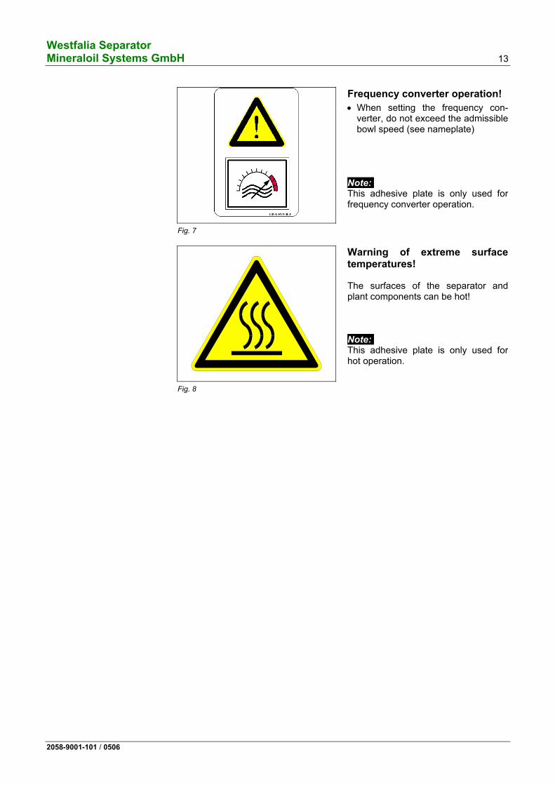
Fig. 7
Frequency converter operation!
• When setting the frequency con-verter, do not exceed the admissible bowl speed (see nameplate)
Note: This adhesive plate is only used for frequency converter operation.
Fig. 8
Warning of extreme surface temperatures! The surfaces of the separator and plant components can be hot! Note: This adhesive plate is only used for hot operation.
Westfalia Separator 14 Mineraloil Systems GmbH
2058-9001-101 / 0506
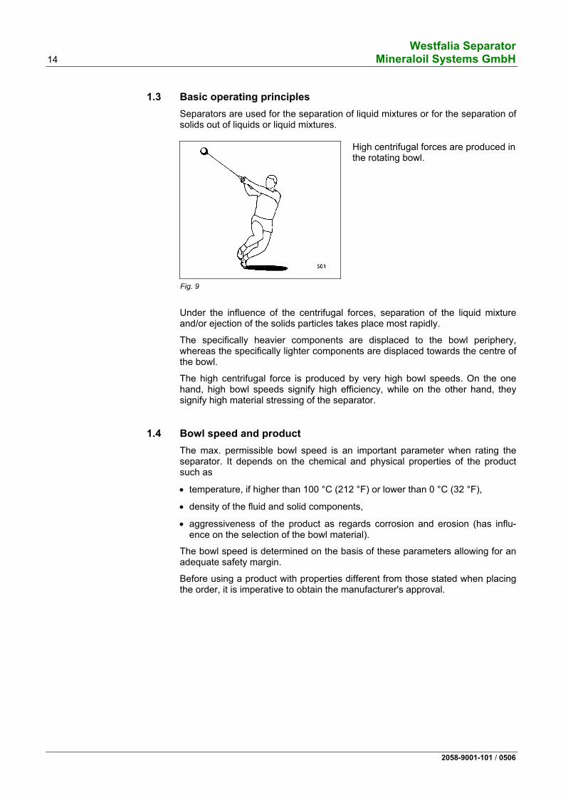
1.3 Basic operating principles Separators are used for the separation of liquid mixtures or for the separation of solids out of liquids or liquid mixtures.
Fig. 9
High centrifugal forces are produced in the rotating bowl.
Under the influence of the centrifugal forces, separation of the liquid mixture and/or ejection of the solids particles takes place most rapidly.
The specifically heavier components are displaced to the bowl periphery, whereas the specifically lighter components are displaced towards the centre of the bowl.
The high centrifugal force is produced by very high bowl speeds. On the one hand, high bowl speeds signify high efficiency, while on the other hand, they signify high material stressing of the separator.
1.4 Bowl speed and product The max. permissible bowl speed is an important parameter when rating the separator. It depends on the chemical and physical properties of the product such as
• temperature, if higher than 100 °C (212 °F) or lower than 0 °C (32 °F),
• density of the fluid and solid components,
• aggressiveness of the product as regards corrosion and erosion (has influ-ence on the selection of the bowl material).
The bowl speed is determined on the basis of these parameters allowing for an adequate safety margin.
Before using a product with properties different from those stated when placing the order, it is imperative to obtain the manufacturer's approval.
Westfalia Separator Mineraloil Systems GmbH 15
2058-9001-101 / 0506
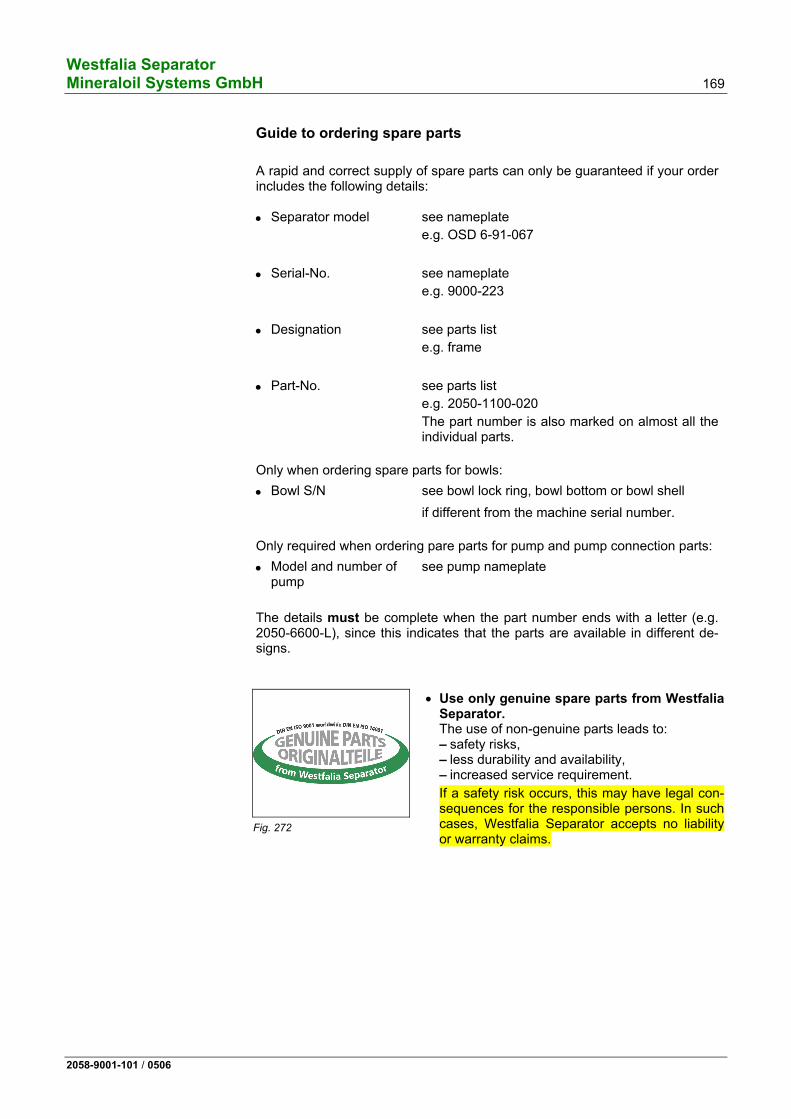
1.5 Demands relating to service personnel and spare parts
Fig. 10
• Use only genuine spare parts from Westfalia Separator. The use of non-genuine parts leads to: – Safety risks – Lower durability and availability – Increased maintenance requirement
If a safety risk arises, this may have legal con-sequences for the responsible persons. In this case, Westfalia Separator shall assume no li-ability or warranty.
• Deploy only well trained personnel for maintenance work, e.g. service per-sonnel from Westfalia Separator or personnel trained by Westfalia Separator. An incorrectly maintained/assembled machine poses a safety risk for the op-erators.
Westfalia Separator 16 Mineraloil Systems GmbH
2058-9001-101 / 0506
1.6 Operations on the separator
Fig. 11
The separator works reliably, provided that it is operated and maintained in accordance with our operating instruc-tions.
Special attention must be given to: • assembly • starting • shutting-down • maintenance and servicing
1.6.1 Assembly
Fig. 12
• If the plant has several centrifuges, be careful not to interchange parts of different bowls since each bowl has been balanced individually. The bowl parts are marked with the serial-number of the machine or with the last three digits of the serial-number.
Fig. 13
• Damaged parts must be replaced immediately by new parts.
Westfalia Separator Mineraloil Systems GmbH 17
2058-9001-101 / 0506
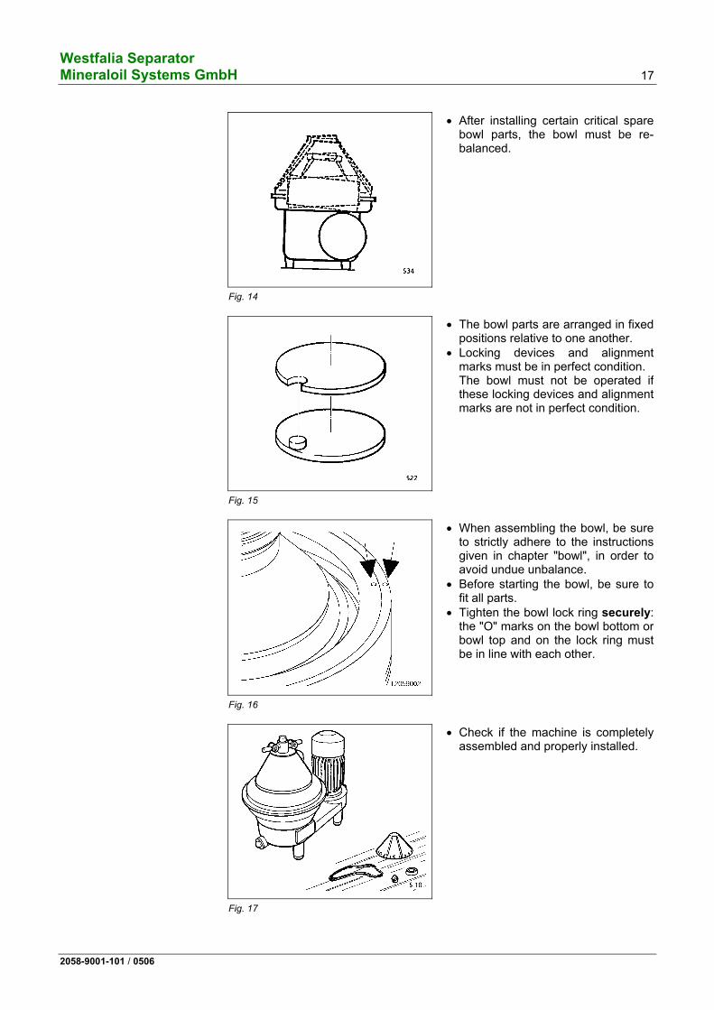
Fig. 14
• After installing certain critical spare bowl parts, the bowl must be re-balanced.
Fig. 15
• The bowl parts are arranged in fixed positions relative to one another.
• Locking devices and alignment marks must be in perfect condition. The bowl must not be operated if these locking devices and alignment marks are not in perfect condition.
Fig. 16
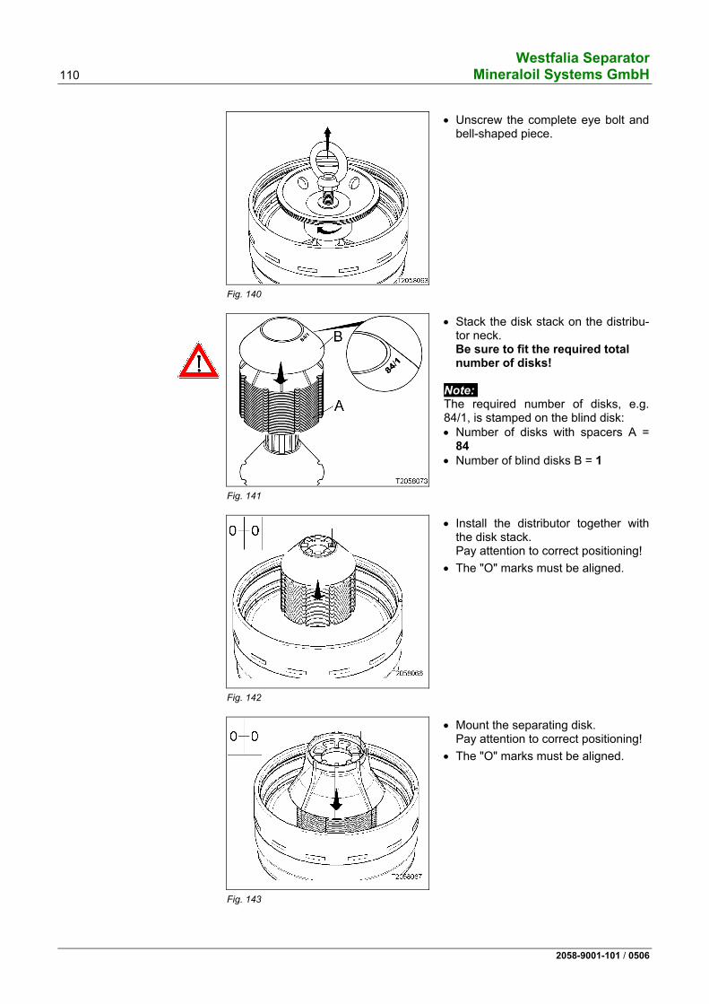
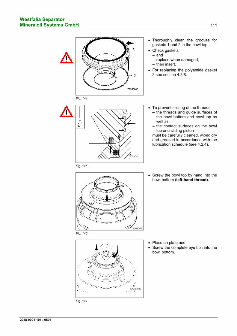
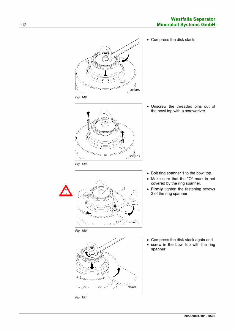
• When assembling the bowl, be sure to strictly adhere to the instructions given in chapter "bowl", in order to avoid undue unbalance.
• Before starting the bowl, be sure to fit all parts.
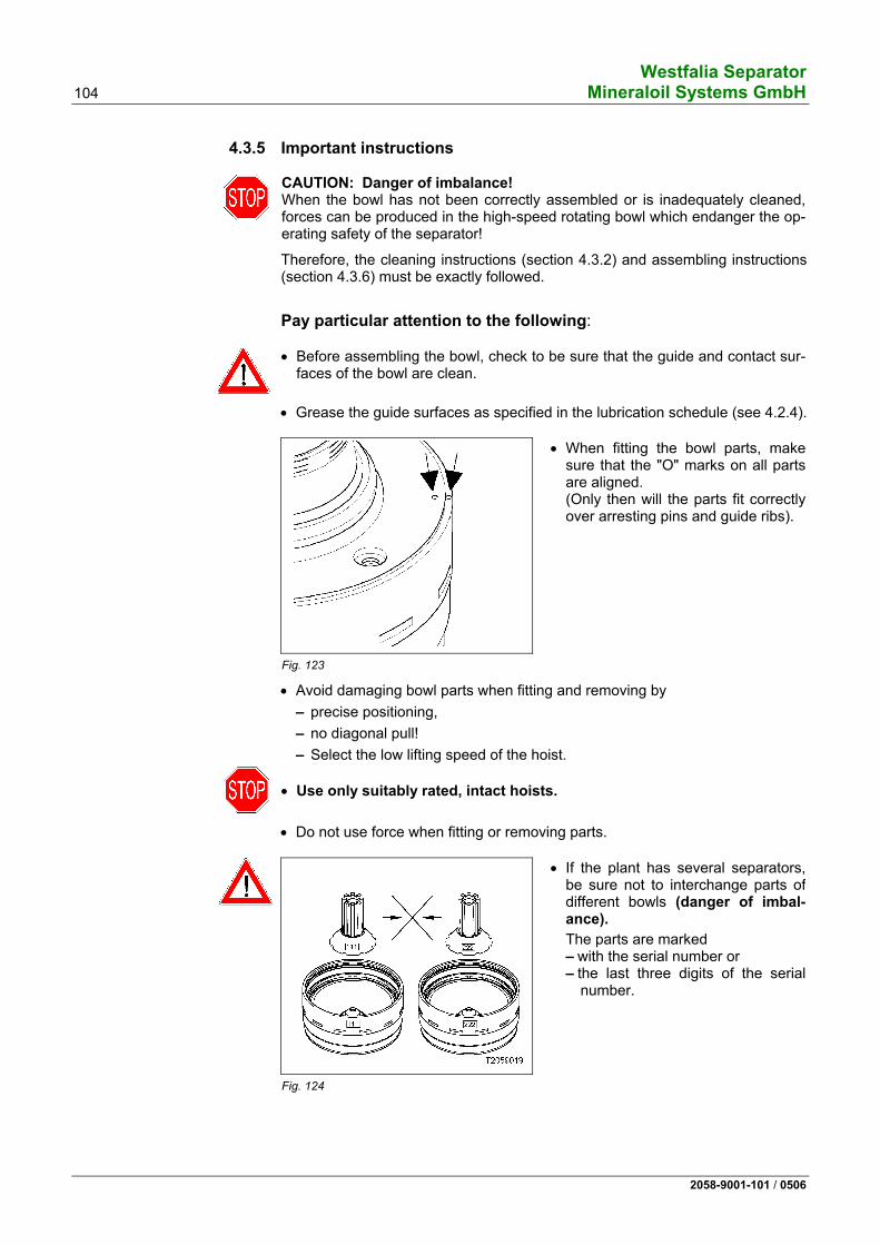
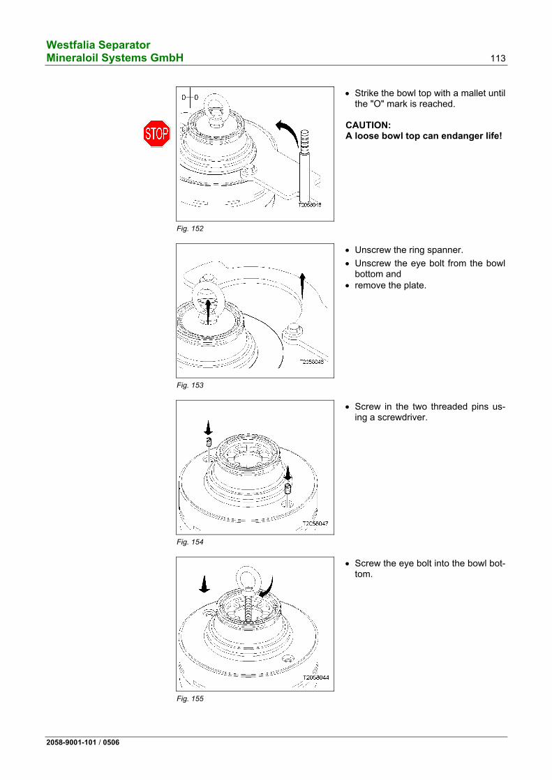
• Tighten the bowl lock ring securely: the "O" marks on the bowl bottom or bowl top and on the lock ring must be in line with each other.
Fig. 17
• Check if the machine is completely assembled and properly installed.
Westfalia Separator 18 Mineraloil Systems GmbH
2058-9001-101 / 0506
Fig. 18
• Carefully fasten hood 1, feed and discharge housing 2 and centripetal pump 3.
1.6.2 Electrical appliances
Fig. 19
• The governing accident prevention regulations apply for the electrical appliances and installations.
• The frequency and voltage of the power supply must correspond to the machine specifications.
• Carry out voltage equalization. • Observe legal regulations; e.g. in
the EU: – Low-voltage guideline 73/23/EWG– Electro-magnetic compatibility
89/336/EWG.
1.6.3 Before start-up
Fig. 20
• Check that the bowl lock ring has been firmly tightened.
• The "O" marks on bowl bottom or bowl top and on the lock ring must be aligned.
Westfalia Separator Mineraloil Systems GmbH 19
2058-9001-101 / 0506
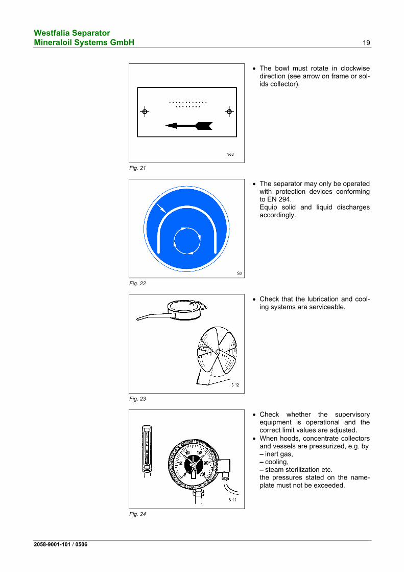
Fig. 21
• The bowl must rotate in clockwise direction (see arrow on frame or sol-ids collector).
Fig. 22
• The separator may only be operated with protection devices conforming to EN 294. Equip solid and liquid discharges accordingly.
Fig. 23
• Check that the lubrication and cool-ing systems are serviceable.
Fig. 24
• Check whether the supervisory equipment is operational and the correct limit values are adjusted.
• When hoods, concentrate collectors and vessels are pressurized, e.g. by– inert gas, – cooling, – steam sterilization etc. the pressures stated on the name-plate must not be exceeded.
Westfalia Separator 20 Mineraloil Systems GmbH
2058-9001-101 / 0506
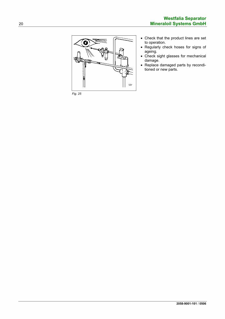
Fig. 25
• Check that the product lines are set to operation.
• Regularly check hoses for signs of ageing.
• Check sight glasses for mechanical damage.
• Replace damaged parts by recondi-tioned or new parts.
Westfalia Separator Mineraloil Systems GmbH 21
2058-9001-101 / 0506
1.6.4 Starting
Fig. 26
• Refer to chapter “operation”.
• Note nameplate. The values for – bowl speed, – density of the heavy liquid, – density of the solids (centrifugally
dry) are maximum values and must not be exceeded.
Fig. 27
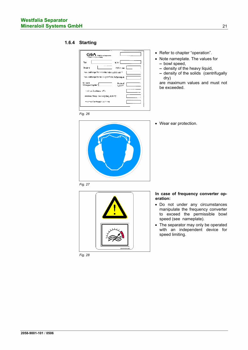
• Wear ear protection.
Fig. 28
In case of frequency converter op-eration:
• Do not under any circumstances manipulate the frequency converter to exceed the permissible bowl speed (see nameplate).
• The separator may only be operated with an independent device for speed limiting.
Westfalia Separator 22 Mineraloil Systems GmbH
2058-9001-101 / 0506
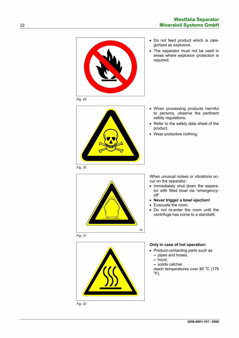
Fig. 29
• Do not feed product which is cate-gorised as explosive.
• The separator must not be used in areas where explosion protection is required.
Fig. 30
• When processing products harmful to persons, observe the pertinent safety regulations.
• Refer to the safety data sheet of the product.
• Wear protective clothing.
Fig. 31
When unusual noises or vibrations oc-cur on the separator: • Immediately shut down the separa-
tor with filled bowl via “emergency-off”.
• Never trigger a bowl ejection! • Evacuate the room. • Do not re-enter the room until the
centrifuge has come to a standstill.
Fig. 32
Only in case of hot operation:
• Product-contacting parts such as – pipes and hoses, – hood, – solids catcher reach temperatures over 80 oC (176 oF).
Westfalia Separator Mineraloil Systems GmbH 23
2058-9001-101 / 0506
Fig. 33
• The bowl is not allowed to run with-out liquid supply for more than 15 minutes, as otherwise it would result in overheating of the bowl material.
1.6.5 Shut-down and »Emergency-Off«
Fig. 34
• For shut-down refer to the chapter "operation".
Westfalia Separator 24 Mineraloil Systems GmbH
2058-9001-101 / 0506
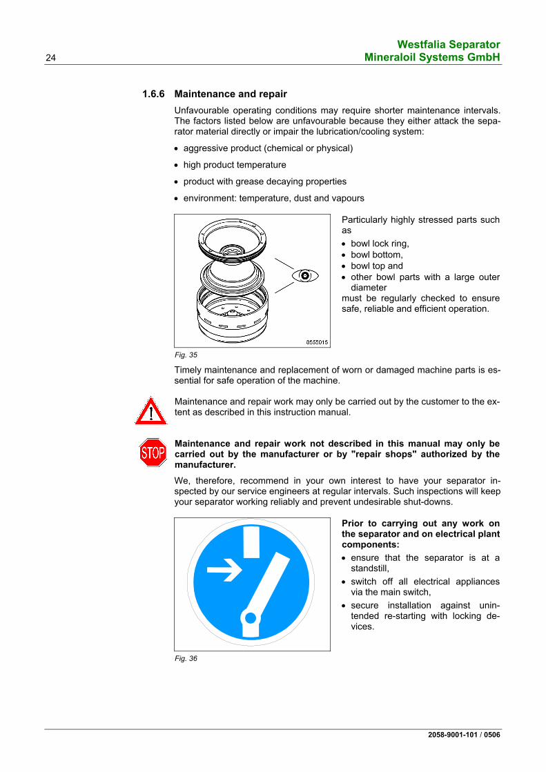
1.6.6 Maintenance and repair Unfavourable operating conditions may require shorter maintenance intervals. The factors listed below are unfavourable because they either attack the sepa-rator material directly or impair the lubrication/cooling system:
• aggressive product (chemical or physical)
• high product temperature
• product with grease decaying properties
• environment: temperature, dust and vapours
Fig. 35
Particularly highly stressed parts such as
• bowl lock ring, • bowl bottom, • bowl top and • other bowl parts with a large outer
diameter must be regularly checked to ensure safe, reliable and efficient operation.
Timely maintenance and replacement of worn or damaged machine parts is es-sential for safe operation of the machine.
Maintenance and repair work may only be carried out by the customer to the ex-tent as described in this instruction manual.
Maintenance and repair work not described in this manual may only be carried out by the manufacturer or by "repair shops" authorized by the manufacturer.
We, therefore, recommend in your own interest to have your separator in-spected by our service engineers at regular intervals. Such inspections will keep your separator working reliably and prevent undesirable shut-downs.
Fig. 36
Prior to carrying out any work on the separator and on electrical plant components:
• ensure that the separator is at a standstill,
• switch off all electrical appliances via the main switch,
• secure installation against unin-tended re-starting with locking de-vices.
Westfalia Separator Mineraloil Systems GmbH 25
2058-9001-101 / 0506
Fig. 37
• Do not loosen any part, nor carry out any maintenance or repair work before the bowl has come to a standstill.
Check for standstill as described under “Bowl”.
Fig. 38
• Do not climb onto or stand on the machine or parts of the machine.
• Make provision for and use a sturdy working platform.
Fig. 39
• Place dismantled machine parts on a suitable base, e.g. rubber mat.
• Take steps to prevent machine parts from overturning and rolling away.
Westfalia Separator 26 Mineraloil Systems GmbH
2058-9001-101 / 0506
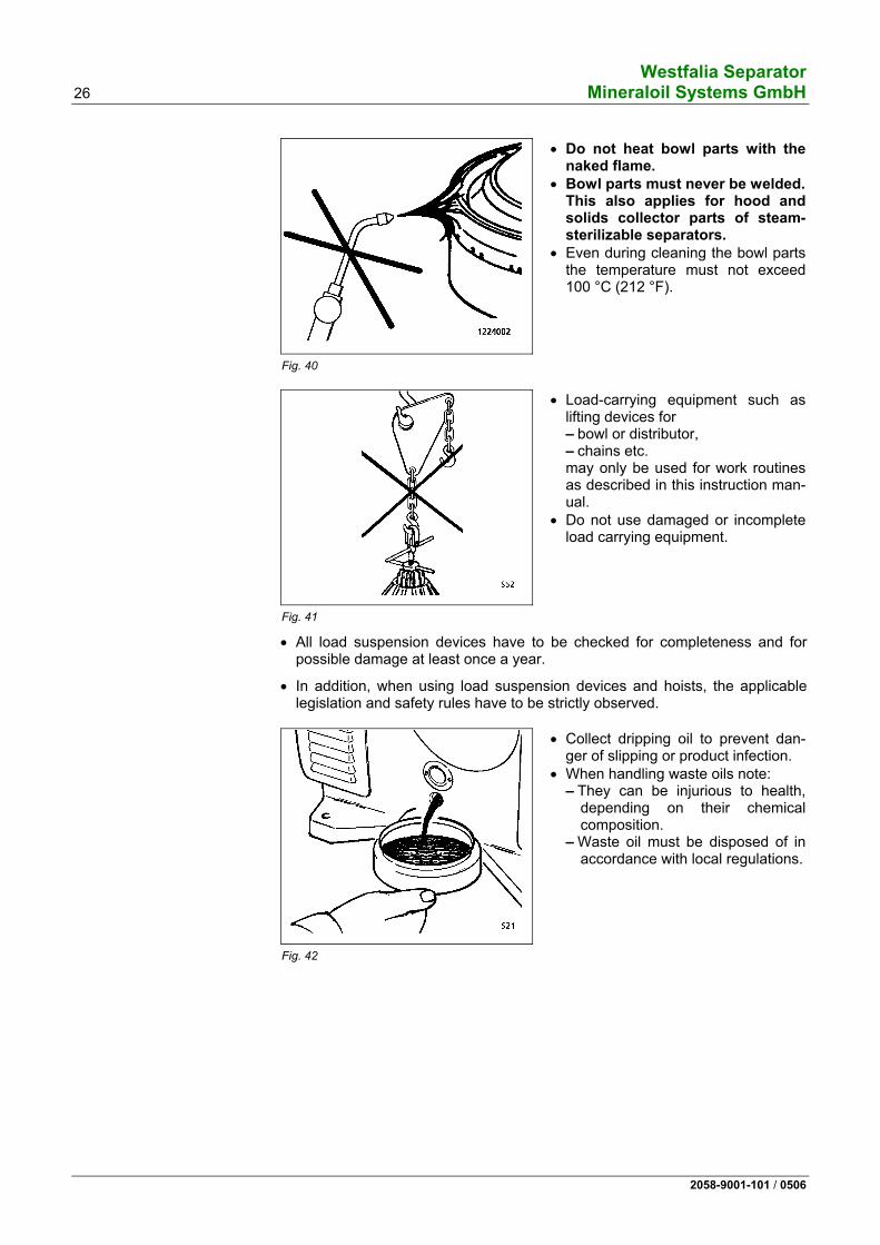
Fig. 40
• Do not heat bowl parts with the naked flame.
• Bowl parts must never be welded.This also applies for hood and solids collector parts of steam-sterilizable separators.
• Even during cleaning the bowl parts the temperature must not exceed 100 °C (212 °F).
Fig. 41
• Load-carrying equipment such as lifting devices for – bowl or distributor, – chains etc. may only be used for work routines as described in this instruction man-ual.
• Do not use damaged or incomplete load carrying equipment.
• All load suspension devices have to be checked for completeness and for possible damage at least once a year.
• In addition, when using load suspension devices and hoists, the applicable legislation and safety rules have to be strictly observed.
Fig. 42
• Collect dripping oil to prevent dan-ger of slipping or product infection.
• When handling waste oils note: – They can be injurious to health,
depending on their chemical composition.
– Waste oil must be disposed of in accordance with local regulations.
Westfalia Separator Mineraloil Systems GmbH 27
2058-9001-101 / 0506
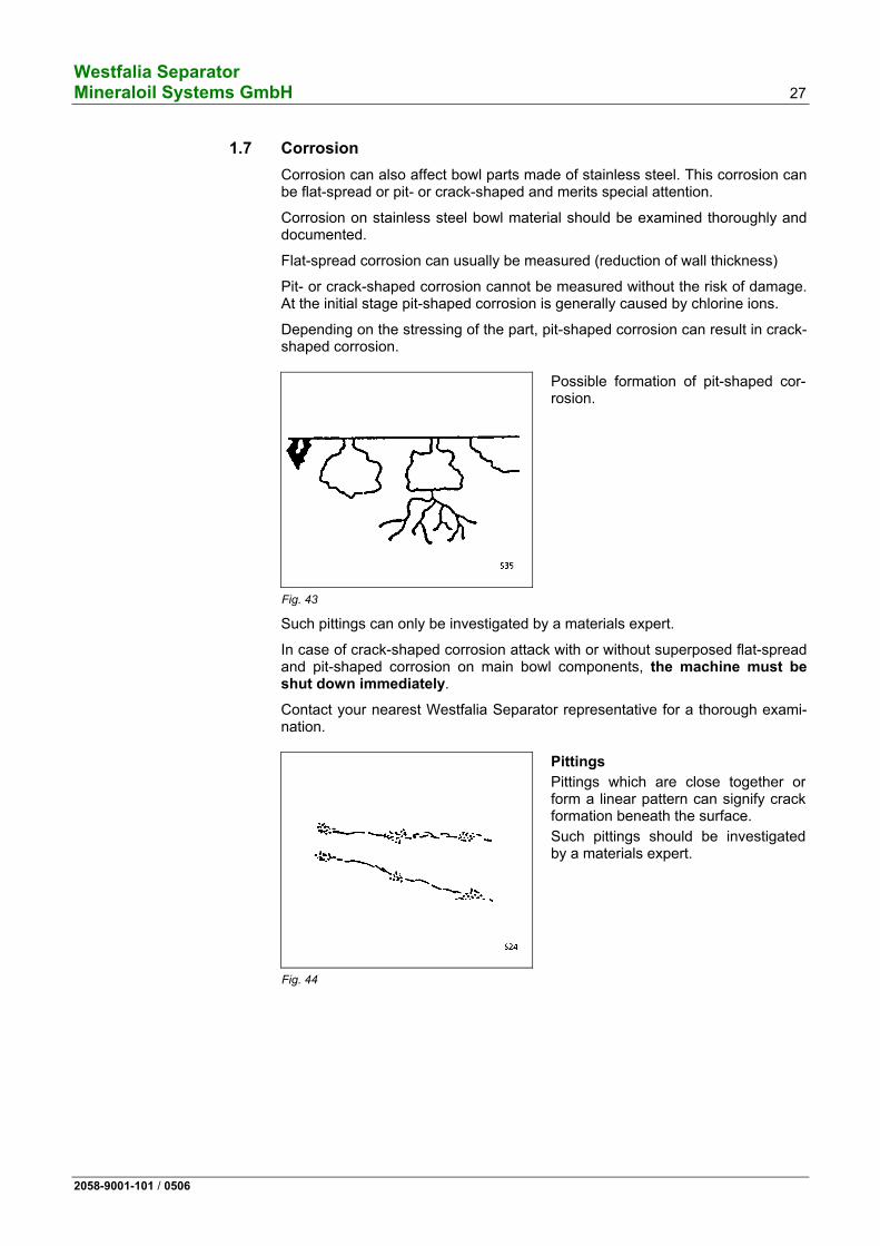
1.7 Corrosion Corrosion can also affect bowl parts made of stainless steel. This corrosion can be flat-spread or pit- or crack-shaped and merits special attention.
Corrosion on stainless steel bowl material should be examined thoroughly and documented.
Flat-spread corrosion can usually be measured (reduction of wall thickness)
Pit- or crack-shaped corrosion cannot be measured without the risk of damage. At the initial stage pit-shaped corrosion is generally caused by chlorine ions.
Depending on the stressing of the part, pit-shaped corrosion can result in crack-shaped corrosion.
Fig. 43
Possible formation of pit-shaped cor-rosion.
Such pittings can only be investigated by a materials expert.
In case of crack-shaped corrosion attack with or without superposed flat-spread and pit-shaped corrosion on main bowl components, the machine must be shut down immediately.
Contact your nearest Westfalia Separator representative for a thorough exami-nation.
Fig. 44
Pittings
Pittings which are close together or form a linear pattern can signify crack formation beneath the surface.
Such pittings should be investigated by a materials expert.
Westfalia Separator 28 Mineraloil Systems GmbH
2058-9001-101 / 0506
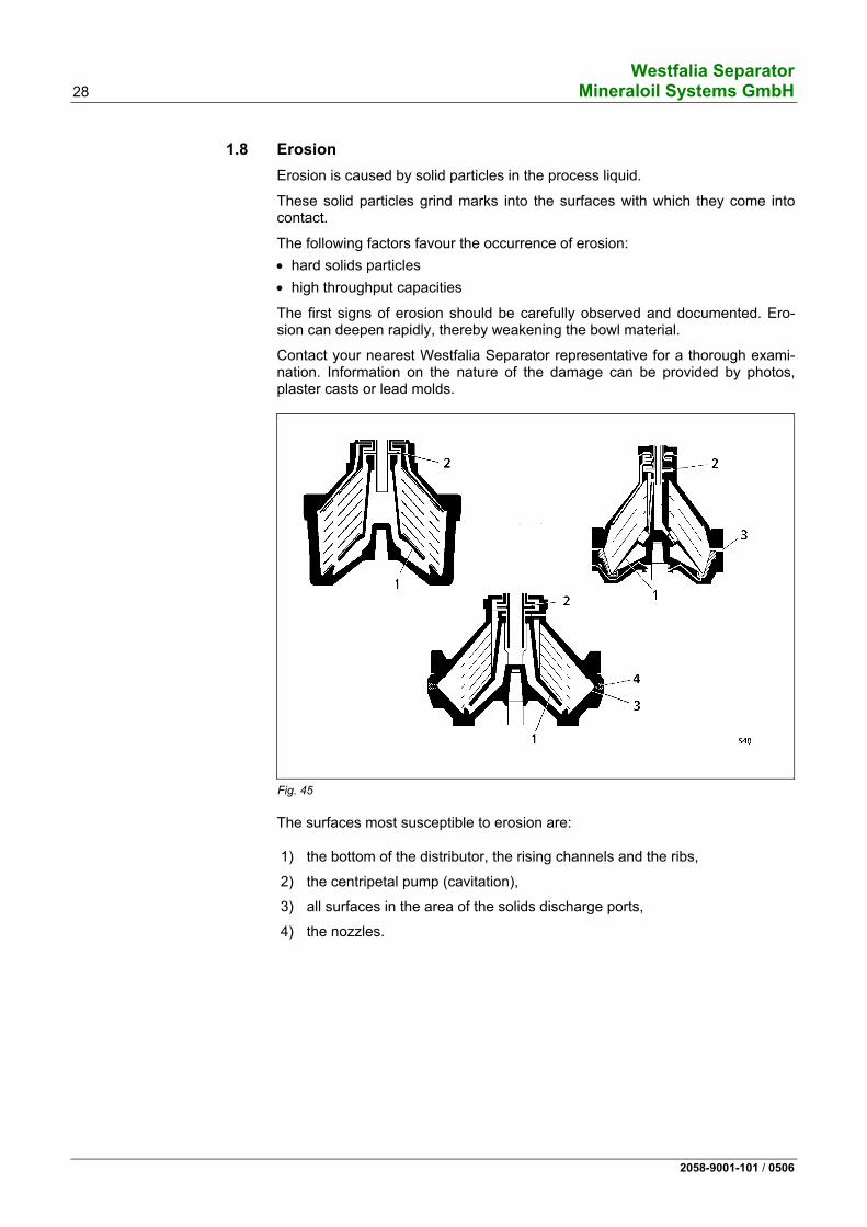
1.8 Erosion Erosion is caused by solid particles in the process liquid.
These solid particles grind marks into the surfaces with which they come into contact.
The following factors favour the occurrence of erosion: • hard solids particles • high throughput capacities
The first signs of erosion should be carefully observed and documented. Ero-sion can deepen rapidly, thereby weakening the bowl material.
Contact your nearest Westfalia Separator representative for a thorough exami-nation. Information on the nature of the damage can be provided by photos, plaster casts or lead molds.
Fig. 45 The surfaces most susceptible to erosion are:
1) the bottom of the distributor, the rising channels and the ribs,
2) the centripetal pump (cavitation),
3) all surfaces in the area of the solids discharge ports,
4) the nozzles.
Westfalia Separator Mineraloil Systems GmbH 29
2058-9001-101 / 0506
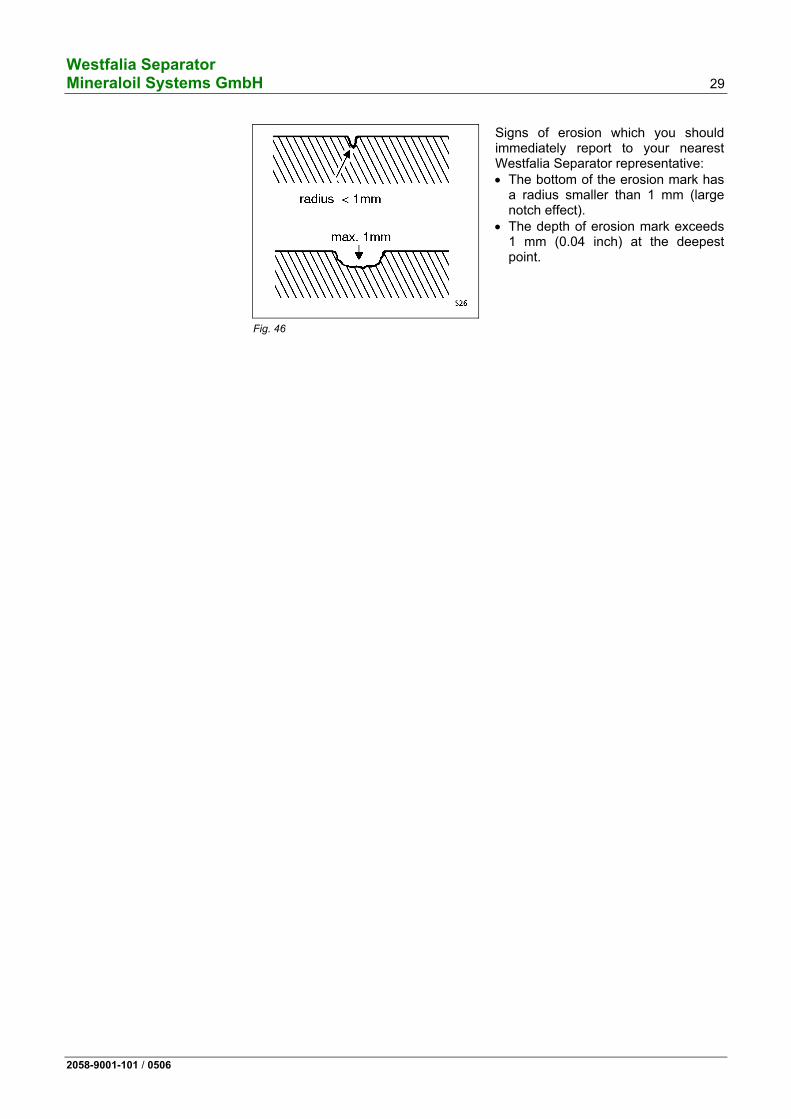
Fig. 46
Signs of erosion which you should immediately report to your nearest Westfalia Separator representative: • The bottom of the erosion mark has
a radius smaller than 1 mm (large notch effect).
• The depth of erosion mark exceeds 1 mm (0.04 inch) at the deepest point.
Westfalia Separator 30 Mineraloil Systems GmbH
2058-9001-101 / 0506
1.9 The health hazards involved when handling heavy oils and lube oils
As a result of the deterioration in quality of fuel oils, the danger has arisen that the heavy oils used on board contain greater amounts of substances injurious to health. These include: - polycyclic aromatic hydrocarbons, - lead compounds, - chemical residues. An increased amount of polycyclic aromatic hydrocarbons is also present in used lube oils (waste oils). The health hazards for the engine room staff depend to a large extent • on the concentrations of the dangerous substances, • the ambient air (inhalation of oil vapours/oil mist), • the intensity and duration of the contact with the skin or mucous membrane.
Possible short-term effects: • headaches, • dizziness, • nausea, • itching or burning of the skin,
Possible long-term effects: • allergic reactions, especially skin allergies, • festering inflammation of the skin pores (oil-acne), • damage to the central nervous system after inhalation over a long period, • skin cancer caused by direct skin contact over a long period, • Lung cancer or cancer of the digestive organs after inhalation over a long period
(not certain as the causes are difficult to separate from the effects of smoking and alcohol). 1.9.1 Code of practice and personal protective measures
• Avoid skin contact with heavy oils or lube oils if possible! - Wear suitable protective gloves. - Apply a protective ointment to the skin (e.g. ointment no. 76), especially if no protective gloves are
worn! • Avoid breathing in oil vapours if possible! • If possible, improve the air circulation in the room!
Fully open the air regulation flaps in the outlets of the air supply ducts in the centrifuge and filter area. • Wash affected areas of skin frequently and thoroughly!
Apply protective ointment to the skin! • Personal hygiene is of the utmost importance! • Change dirty overalls regularly! • Exercise special care when carrying out maintenance work on and cleaning heavy oil and lube oil cen-
trifuges and filters!
Westfalia Separator Mineraloil Systems GmbH 31
2058-9001-101 / 0506
2 Machine description
2.1 Dimensioned drawing of the separator..................................................32 2.2 Section through separator .....................................................................34 2.3 General ..................................................................................................35 2.4 OSD ...-91-… .........................................................................................35 2.5 Main components of the separator ........................................................38 2.5.1 Bowl .......................................................................................................39 2.5.2 Bowl hydraulic system ...........................................................................40 2.5.3 Centripetal pump ...................................................................................43 2.5.4 Sensing liquid pump ..............................................................................44 2.5.5 Drive.......................................................................................................45 2.6 The regulating ring.................................................................................46 2.6.1 Determining the size of the regulating ring with the aid of the diagram..................................................................................................46 2.6.2 Determining the regulating ring by experiment......................................48 2.7 Technical data .......................................................................................50
Westfalia Separator 32 Mineraloil Systems GmbH
2058-9001-101 / 0506
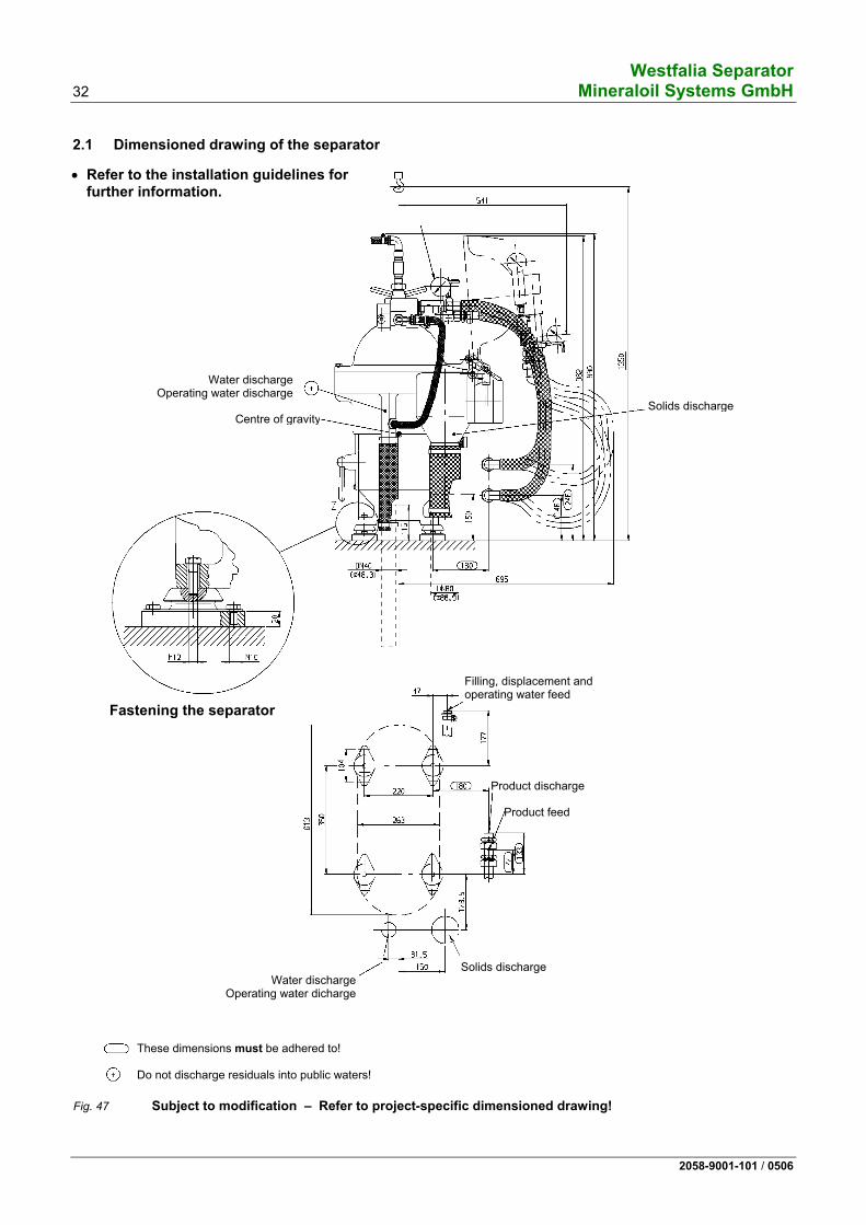
2.1 Dimensioned drawing of the separator
Fig. 47 Subject to modification – Refer to project-specific dimensioned drawing!
Solids discharge
Filling, displacement and operating water feed
Product discharge
Product feed
Solids discharge Water discharge
Operating water dicharge
Fastening the separator
Water dischargeOperating water discharge
Centre of gravity
These dimensions must be adhered to!
Do not discharge residuals into public waters!
• Refer to the installation guidelines for further information.
Westfalia Separator Mineraloil Systems GmbH 33
2058-9001-101 / 0506
Fig. 48 Subject to modification – Refer to project-specific dimensioned drawing!
Water discharge Operating water dis-charge
Centre of gravity
Solids discharge
Filling, displacement and operatingwater feed
These dimensions must be adhered to!
Do not discharge residuals into public waters!
Product feed
Product dischargeDischarge by the centripetal pump built into the
separator
Pressure switch (water discharge)
Pressure switch(product discharge)
The separator foundation must not have contact with foundations of other units (e.g. aux-iliary diesel engines, pumps) to avoid damage to all bearings.
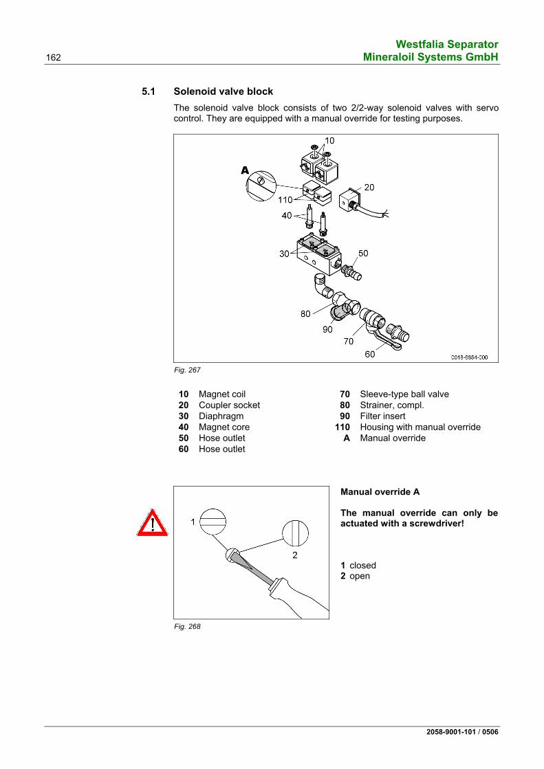
Solenoid valve block
Removal length for motor clamp screw
Westfalia Separator 34 Mineraloil Systems GmbH
2058-9001-101 / 0506
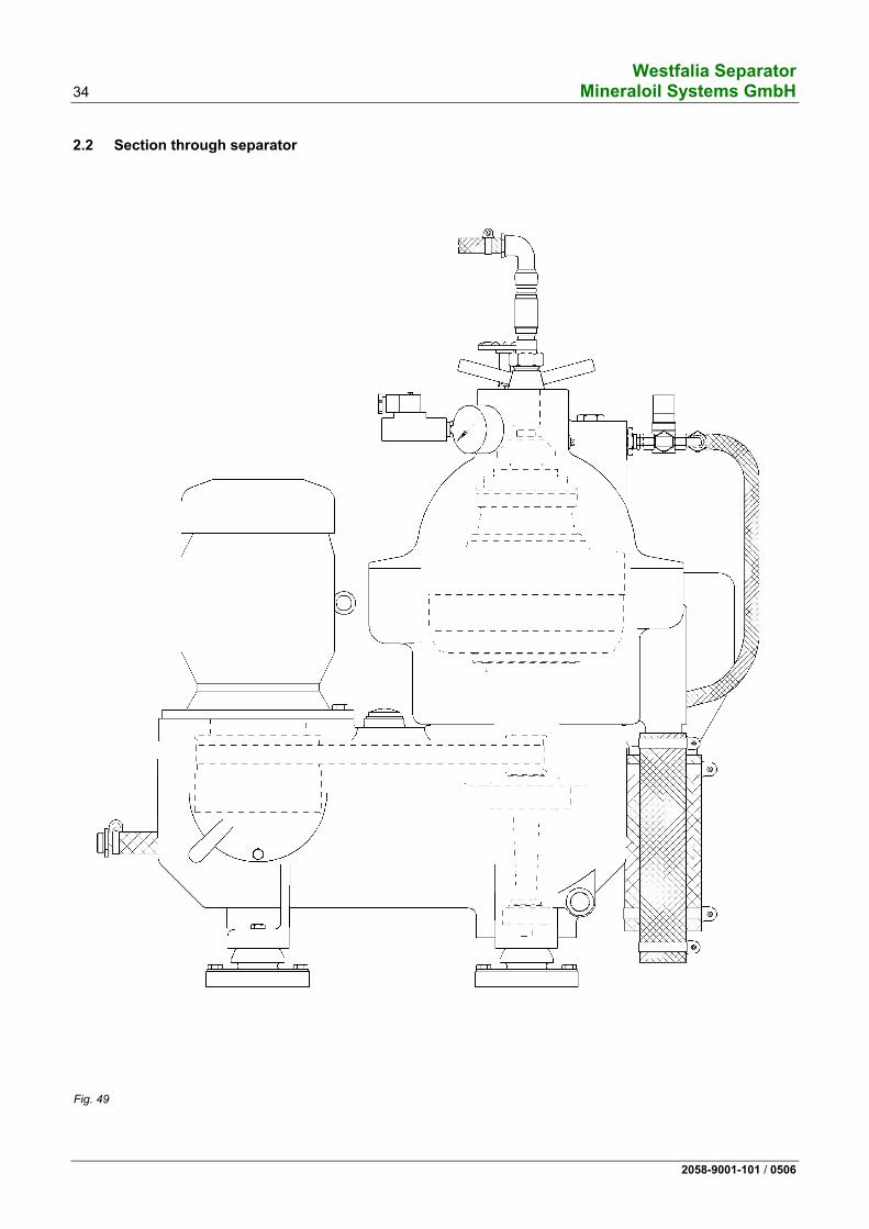
2.2 Section through separator
Fig. 49
Westfalia Separator Mineraloil Systems GmbH 35
2058-9001-101 / 0506
2.3 General The machine described in this manual is a high-speed centrifugal separator with self-cleaning bowl.
"Separation" means the separation of liquid mixtures which consist of two liq-uids, with simultaneous removal of the solids contained in the liquids.
"Clarification" is the removal of solids from a liquid.
Prerequisite for treatment technology (separation) is that the components of the product
– can be separated mechanically, – have different densities and – do not emulsify.
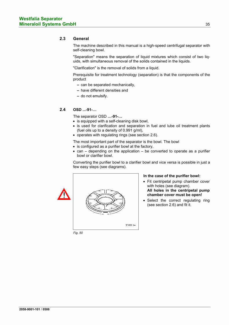
2.4 OSD ...-91-… The separator OSD …-91-… • is equipped with a self-cleaning disk bowl, • is used for clarification and separation in fuel and lube oil treatment plants
(fuel oils up to a density of 0.991 g/ml), • operates with regulating rings (see section 2.6).
The most important part of the separator is the bowl. The bowl • is configured as a purifier bowl at the factory, • can – depending on the application – be converted to operate as a purifier
bowl or clarifier bowl.
Converting the purifier bowl to a clarifier bowl and vice versa is possible in just a few easy steps (see diagrams).
Fig. 50
In the case of the purifier bowl:
• Fit centripetal pump chamber cover with holes (see diagram). All holes in the centripetal pump chamber cover must be open!
• Select the correct regulating ring (see section 2.6) and fit it.
Westfalia Separator 36 Mineraloil Systems GmbH
2058-9001-101 / 0506
Fig. 51
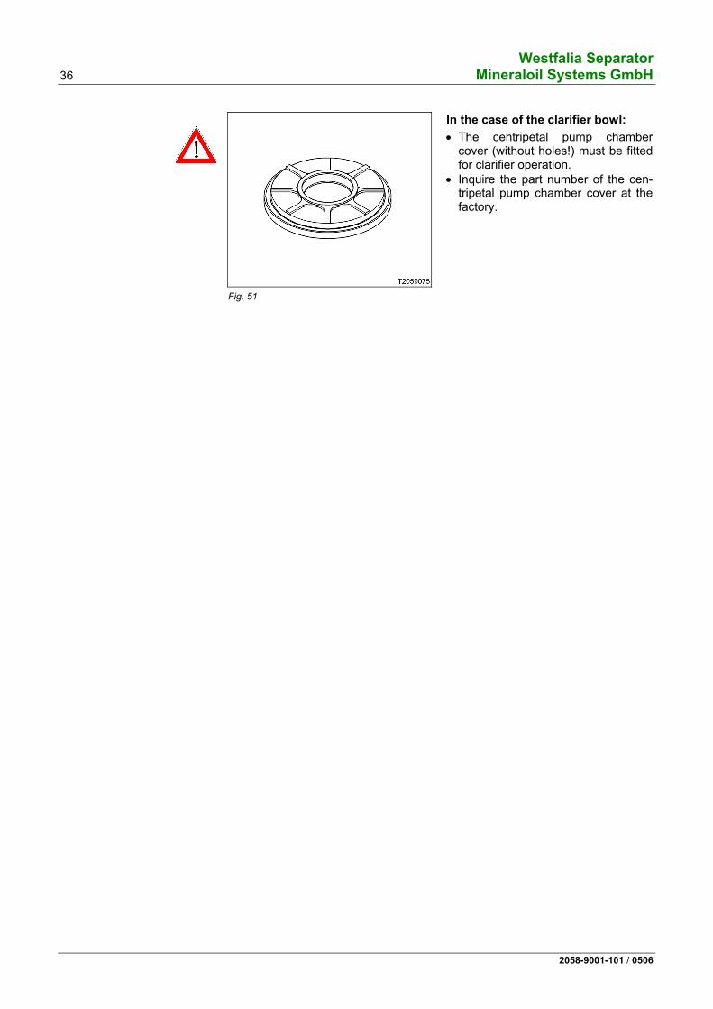
In the case of the clarifier bowl:
• The centripetal pump chamber cover (without holes!) must be fitted for clarifier operation.
• Inquire the part number of the cen-tripetal pump chamber cover at the factory.
Westfalia Separator Mineraloil Systems GmbH 37
2058-9001-101 / 0506
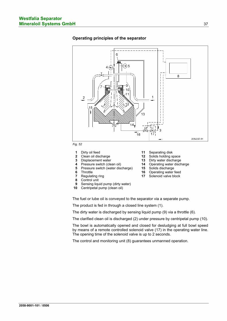
Operating principles of the separator
Fig. 52
1 Dirty oil feed 2 Clean oil discharge 3 Displacement water 4 Pressure switch (clean oil) 5 Pressure switch (water discharge) 6 Throttle 7 Regulating ring 8 Control unit 9 Sensing liquid pump (dirty water) 10 Centripetal pump (clean oil)
11 Separating disk 12 Solids holding space 13 Dirty water discharge 14 Operating water discharge 15 Solids discharge 16 Operating water feed 17 Solenoid valve block
The fuel or lube oil is conveyed to the separator via a separate pump.
The product is fed in through a closed line system (1).
The dirty water is discharged by sensing liquid pump (9) via a throttle (6).
The clarified clean oil is discharged (2) under pressure by centripetal pump (10).
The bowl is automatically opened and closed for desludging at full bowl speed by means of a remote controlled solenoid valve (17) in the operating water line. The opening time of the solenoid valve is up to 2 seconds.
The control and monitoring unit (8) guarantees unmanned operation.
Westfalia Separator 38 Mineraloil Systems GmbH
2058-9001-101 / 0506
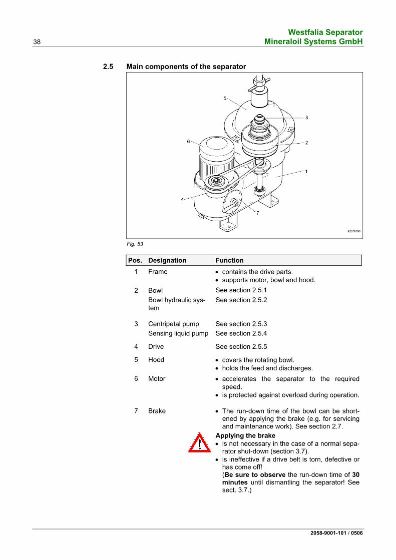
2.5 Main components of the separator
Fig. 53
Pos. Designation Function
1 Frame • contains the drive parts. • supports motor, bowl and hood.
2 Bowl See section 2.5.1 Bowl hydraulic sys-
tem
See section 2.5.2
3 Centripetal pump See section 2.5.3 Sensing liquid pump See section 2.5.4
4 Drive See section 2.5.5
5 Hood • covers the rotating bowl. • holds the feed and discharges.
6 Motor • accelerates the separator to the required speed.
• is protected against overload during operation.
7 Brake • The run-down time of the bowl can be short-ened by applying the brake (e.g. for servicing and maintenance work). See section 2.7.
Applying the brake • is not necessary in the case of a normal sepa-
rator shut-down (section 3.7). • is ineffective if a drive belt is torn, defective or
has come off! (Be sure to observe the run-down time of 30minutes until dismantling the separator! See sect. 3.7.)
Westfalia Separator Mineraloil Systems GmbH 39
2058-9001-101 / 0506
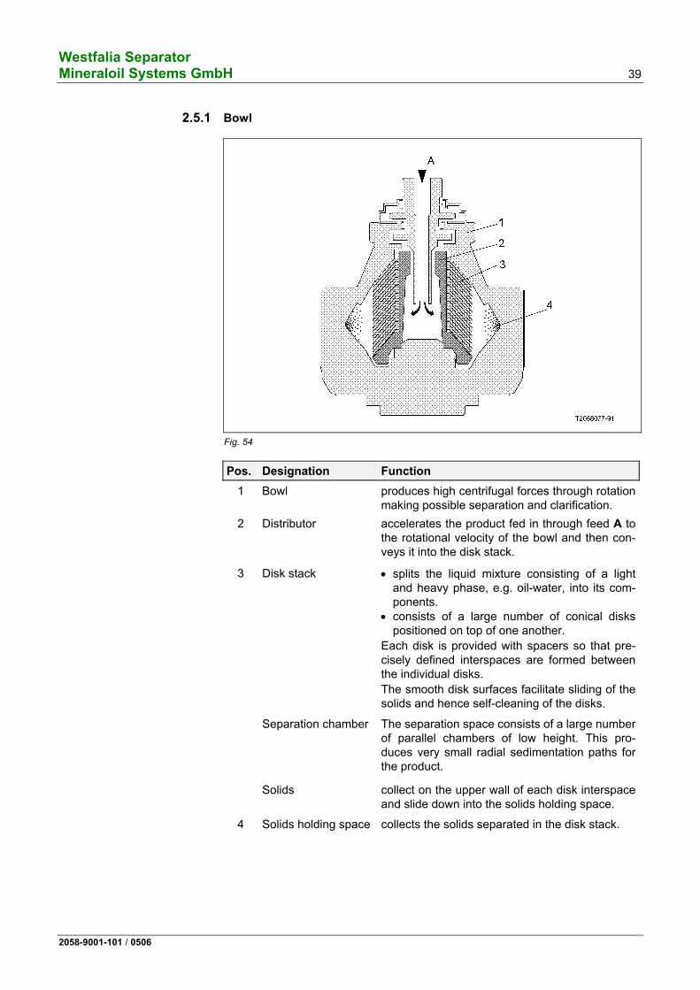
2.5.1 Bowl
Fig. 54
Pos. Designation Function
1 Bowl produces high centrifugal forces through rotation making possible separation and clarification.
2 Distributor accelerates the product fed in through feed A to the rotational velocity of the bowl and then con-veys it into the disk stack.
3 Disk stack • splits the liquid mixture consisting of a light and heavy phase, e.g. oil-water, into its com-ponents.
• consists of a large number of conical disks positioned on top of one another.
Each disk is provided with spacers so that pre-cisely defined interspaces are formed between the individual disks. The smooth disk surfaces facilitate sliding of the solids and hence self-cleaning of the disks.
Separation chamber The separation space consists of a large number of parallel chambers of low height. This pro-duces very small radial sedimentation paths for the product.
Solids collect on the upper wall of each disk interspace and slide down into the solids holding space.
4 Solids holding space collects the solids separated in the disk stack.
Westfalia Separator 40 Mineraloil Systems GmbH
2058-9001-101 / 0506
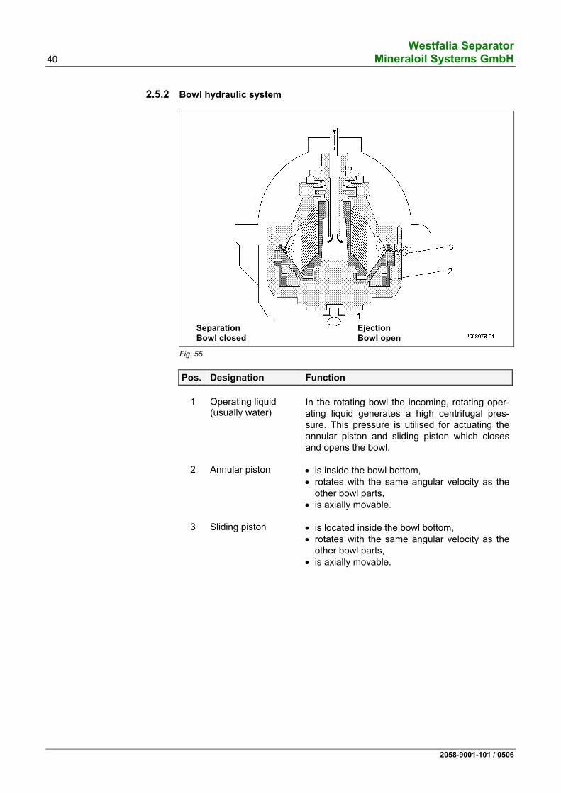
2.5.2 Bowl hydraulic system
SeparationBowl closed
EjectionBowl open
Fig. 55
Pos. Designation Function
1
Operating liquid (usually water)
In the rotating bowl the incoming, rotating oper-ating liquid generates a high centrifugal pres-sure. This pressure is utilised for actuating the annular piston and sliding piston which closes and opens the bowl.
2 Annular piston • is inside the bowl bottom, • rotates with the same angular velocity as the
other bowl parts, • is axially movable.
3 Sliding piston • is located inside the bowl bottom, • rotates with the same angular velocity as the
other bowl parts, • is axially movable.
Westfalia Separator Mineraloil Systems GmbH 41
2058-9001-101 / 0506
Closing the bowl (separation)
Fig. 56
After starting the separator the solenoid valve for operating liquid is actuated with the aid of the control unit, and the bowl is closed as follows:
Pos. Designation Function
1 Operating liquid • flows into the injection chamber 4 of bowl bot-
tom 5 and • from there through feed holes into closing
chamber 6. This initiates closing of the bowl.
2 Annular piston • moves into closed position.
3 Sliding piston • is raised due to the hydrostatic pressure in
closing chamber 6. • is pressed against the gasket 7 of bowl top
due to the hydrostatic pressure and • closes the bowl.
SeparationBowl closed
Ejection Bowl open
Westfalia Separator 42 Mineraloil Systems GmbH
2058-9001-101 / 0506
Opening the bowl (ejection)
Fig. 57
The solenoid valve for operating liquid is opened with the aid of the control unit, and the ejection cycle is triggered as follows:
Pos. Designation Function
1 Operating liquid • flows first into injection chamber 4 and • from there into opening chamber 8.
3 Sliding piston • moves downwards and • opens the ejection ports in bowl bottom 5 for
the separated solids 9.
SeparationBowl closed
Ejection Bowl open
Westfalia Separator Mineraloil Systems GmbH 43
2058-9001-101 / 0506
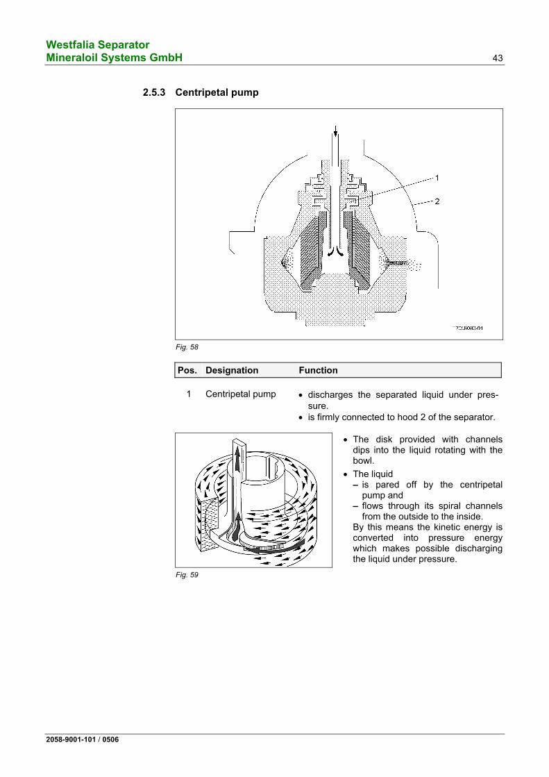
2.5.3 Centripetal pump
Fig. 58
Pos. Designation Function
1 Centripetal pump • discharges the separated liquid under pres-sure.
• is firmly connected to hood 2 of the separator.
Fig. 59
• The disk provided with channels dips into the liquid rotating with the bowl.
• The liquid – is pared off by the centripetal
pump and – flows through its spiral channels
from the outside to the inside. By this means the kinetic energy is converted into pressure energy which makes possible discharging the liquid under pressure.
Westfalia Separator 44 Mineraloil Systems GmbH
2058-9001-101 / 0506
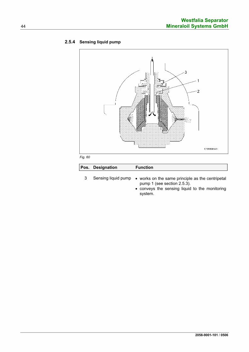
2.5.4 Sensing liquid pump
Fig. 60
Pos. Designation Function
3 Sensing liquid pump • works on the same principle as the centripetal pump 1 (see section 2.5.3).
• conveys the sensing liquid to the monitoring system.
Westfalia Separator Mineraloil Systems GmbH 45
2058-9001-101 / 0506
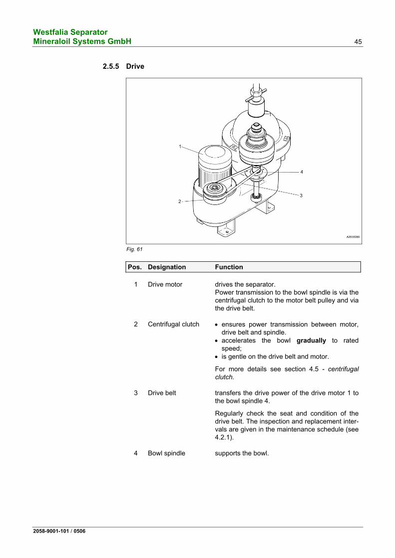
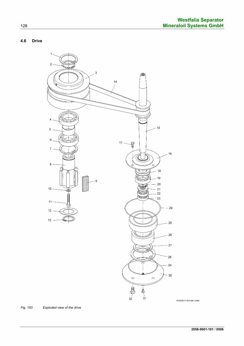
2.5.5 Drive
Fig. 61
Pos. Designation Function
1 Drive motor drives the separator. Power transmission to the bowl spindle is via the centrifugal clutch to the motor belt pulley and via the drive belt.
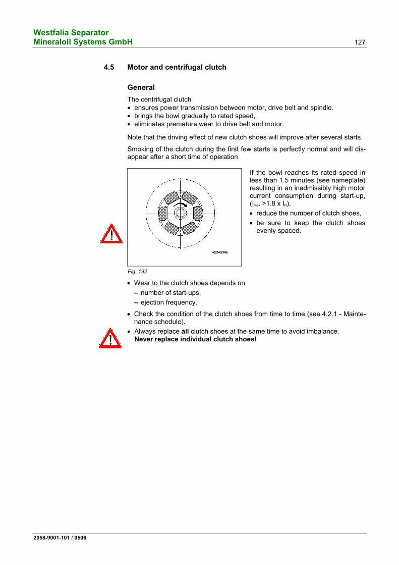
2 Centrifugal clutch • ensures power transmission between motor, drive belt and spindle.
• accelerates the bowl gradually to rated speed;
• is gentle on the drive belt and motor.
For more details see section 4.5 - centrifugal clutch.
3 Drive belt transfers the drive power of the drive motor 1 to the bowl spindle 4.
Regularly check the seat and condition of the drive belt. The inspection and replacement inter-vals are given in the maintenance schedule (see 4.2.1).
4 Bowl spindle supports the bowl.
Westfalia Separator 46 Mineraloil Systems GmbH
2058-9001-101 / 0506
2.6 The regulating ring (using oil purification as an example)
Function of the regulating ring
Optimum dewatering of oils containing water is only possible if the bowl is cor-rectly adjusted to the difference in density between the oil and the water.
The regulating ring with the correct inner diameter, i.e. with the diameter that corresponds to the density difference between the oil and water, should there-fore be selected from the set of regulating rings (with different inner diameters) supplied with the separator and fitted in the bowl.
The inner diameter of the regulating ring to be selected can be determined with the aid of the diagram or by experiment. The rule of thumb is: • small regulating ring for heavy oil, • large regulating ring for light oil.
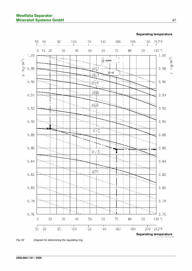
2.6.1 Determining the size of the regulating ring with the aid of the diagram (using oil purification as an example)
The diagram can be used to determine – the inner diameter of the regulating ring and, – if desired, the density of the oil
for a given separating temperature, provided that the density of the oil is known at a temperature between 15 oC and 90 oC.
Example
Given:
– Density of oil at 20 oC ρoil 20 °C = 0.89 kg/dm3
– Separating temperature t = 70 oC
To be determined:
– Inner diameter of regulating ring d = ? – Density of oil at 70 oC ρoil 70 °C = ?
Determined:
– Inner diameter of the regulating ring according to the diagram d = 73 mm
– Density of oil at 70 oC according to the diagram ρoil 70 °C = 0.858 kg/dm3
If no regulating ring with the determined inner diameter is available, a smaller ring can be machined to the required size. Before doing that, however, check by experiment whether the regulating rings furnished with the separator are ade-quate for optimum dewatering.
Westfalia Separator Mineraloil Systems GmbH 47
2058-9001-101 / 0506
р water
р oil
Separating temperature
Separating temperature
Fig. 62 Diagram for determining the regulating ring
Westfalia Separator 48 Mineraloil Systems GmbH
2058-9001-101 / 0506
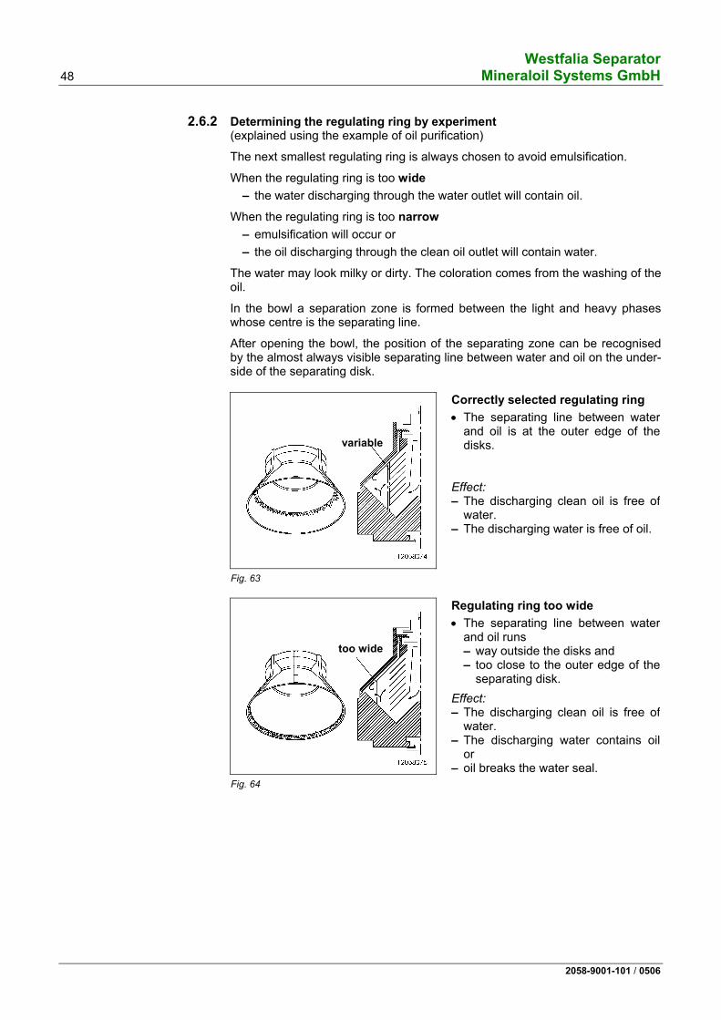
2.6.2 Determining the regulating ring by experiment (explained using the example of oil purification)
The next smallest regulating ring is always chosen to avoid emulsification.
When the regulating ring is too wide – the water discharging through the water outlet will contain oil.
When the regulating ring is too narrow – emulsification will occur or – the oil discharging through the clean oil outlet will contain water.
The water may look milky or dirty. The coloration comes from the washing of the oil.
In the bowl a separation zone is formed between the light and heavy phases whose centre is the separating line.
After opening the bowl, the position of the separating zone can be recognised by the almost always visible separating line between water and oil on the under-side of the separating disk.
variable
Fig. 63
Correctly selected regulating ring
• The separating line between water and oil is at the outer edge of the disks.
Effect: – The discharging clean oil is free of
water. – The discharging water is free of oil.
too wide
Fig. 64
Regulating ring too wide
• The separating line between water and oil runs – way outside the disks and – too close to the outer edge of the
separating disk.
Effect: – The discharging clean oil is free of
water. – The discharging water contains oil
or – oil breaks the water seal.
Westfalia Separator Mineraloil Systems GmbH 49
2058-9001-101 / 0506
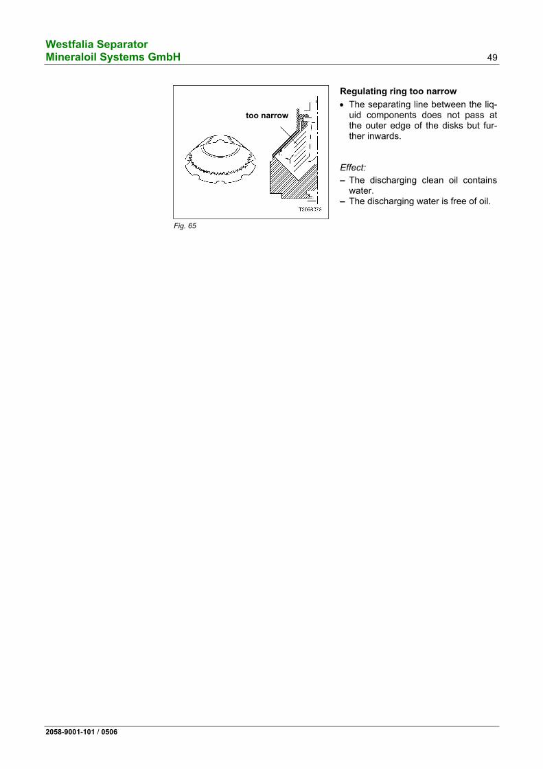
too narrow
Fig. 65
Regulating ring too narrow
• The separating line between the liq-uid components does not pass at the outer edge of the disks but fur-ther inwards.
Effect:
– The discharging clean oil contains water.
– The discharging water is free of oil.
Westfalia Separator 50 Mineraloil Systems GmbH
2058-9001-101 / 0506
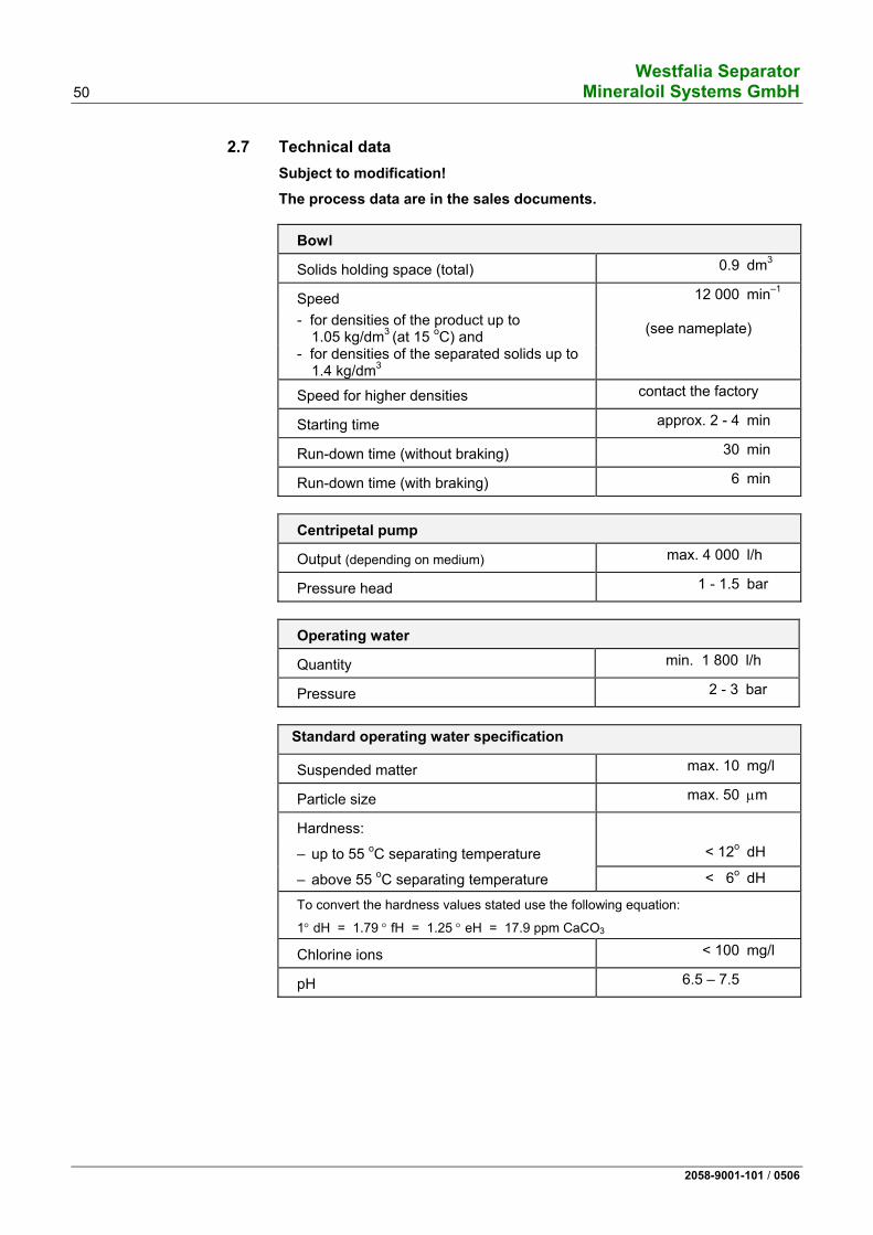
2.7 Technical data Subject to modification!
The process data are in the sales documents.
Bowl
Solids holding space (total) 0.9 dm3
Speed 12 000 min–1
- for densities of the product up to 1.05 kg/dm3 (at 15 oC) and (see nameplate)
- for densities of the separated solids up to 1.4 kg/dm3
Speed for higher densities contact the factory
Starting time approx. 2 - 4 min
Run-down time (without braking) 30 min
Run-down time (with braking) 6 min
Centripetal pump
Output (depending on medium) max. 4 000 l/h
Pressure head 1 - 1.5 bar
Operating water
Quantity min. 1 800 l/h
Pressure 2 - 3 bar
Standard operating water specification
Suspended matter max. 10 mg/l
Particle size max. 50 μm
Hardness:
– up to 55 oC separating temperature < 12o dH
– above 55 oC separating temperature < 6o dH
To convert the hardness values stated use the following equation:
1° dH = 1.79 ° fH = 1.25 ° eH = 17.9 ppm CaCO3
Chlorine ions < 100 mg/l
pH 6.5 – 7.5
Westfalia Separator Mineraloil Systems GmbH 51
2058-9001-101 / 0506
Normal separating temperature of the product
DO 20 °C (68 °F)
MDO 40 °C (104 °F)
LO 90 °C (194 °F)
LO HD 95 °C (203 °F)
HFO 98 °C (208 °F)
Due to the large number of products to be treated, it is not possible to specify an exact separating temperature of the product in this manual. The exact separating temperature of the product (in °C) is stated in the order-specific data sheet.
Motor
Power rating 50 Hz 4 kW
60 Hz 4.8 kW
Speed 50 Hz 3 000 RPM
60 Hz 3 600 RPM
Design IM V1
Enclosure IP 55
Drive 50/60 Hz
Oil filling approx. 2.5 l
Oil quality, see section 4.2.3
Product pump
Pump unit (gear or screw pump)
Output depending on plant rating
Suction height max. 0.4 bar
Pressure head 2 bar
Weights
Separator (with motor, without bowl) 160 kg
Bowl 42 kg
Motor 25 kg
Westfalia Separator 52 Mineraloil Systems GmbH
2058-9001-101 / 0506
Capacity (see sales documents)
The capacity of the separator depends on the • viscosity, • temperature, • density, • degree of contamination, • water content and • the desired degree of purity of the product.
Westfalia Separator Mineraloil Systems GmbH 53
2058-9001-101 / 0506
3 Operation
3.1 Technical information.............................................................................54 3.1.1 Notes on separation...............................................................................54 3.1.2 General information on bowl ejection ....................................................54 3.2 Before start-up .......................................................................................56 3.2.1 Before the first start-up ..........................................................................56 3.2.2 Before every start-up .............................................................................56 3.3 Starting the separator ............................................................................57 3.4 Monitoring of operation..........................................................................57 3.5 Setting the separation time....................................................................58 3.5.1 Mathematical calculation .......................................................................58 3.6 Ejecting the bowl....................................................................................59 3.7 Shutting down the separator..................................................................60 3.8 Trouble shooting ....................................................................................62 3.8.1 Trouble shooting ....................................................................................62 3.8.2 Bowl faults .............................................................................................64
Westfalia Separator 54 Mineraloil Systems GmbH
2058-9001-101 / 0506
3.1 Technical information Take note of the following sections:
3.1.1 Notes on separation The separator is used for clarification and separation in fuel and lube oil treat-ment plants.
The best separation effect is obtained with low viscosity of the product to be separated.
The separator operates economically with the separating temperatures and ca-pacities specified by us.
In the case of deviating products – see sales documents or – inquire at the factory.
Procedure: • Select the desired operating mode on the control unit.
• Set the separating time on the control unit.
• Start the separator (see 3.2).
3.1.2 General information on bowl ejection The bowl is ejected automatically at full speed during the program sequence.
The ejection time is determined by the preset separating time.
For determining the separating time see 3.5.
Sequence of an ejection (example)
1. Separating time has elapsed. 2. Product feed valve is closed. 3. Displacement water displaces the fuel oil to the clean oil side. 4. Operating water opens and closes the bowl hydraulically at full bowl
speed. 5. Waiting time for speed recovery. 6. Filling water supply 7. Product valve is opened. 8. Separating time resumes.
Displacement
• When separating, the loss of feed liquid unavoidable during ejection can be reduced to a minimum by displacing the feed liquid with water before sludge ejection takes place (especially important when processing valuable feed liq-uid).
• The duration of displacement water supply is given in the timer overview (see control unit manual).
Westfalia Separator Mineraloil Systems GmbH 55
2058-9001-101 / 0506
• If the displacement time is too long, water will discharge through the light liq-uid outlet.
• If the displacement time is too short, part of the product remains in the bowl and is lost during desludging.
Flush ejection
If the solids cant be completely ejected, – due to an excessively long dwell time in the bowl or – are stuck to firmly on the wall of the solids holding space due to the solids
properties,
• either the separating time must be shortened or • a flush ejection must be carried out after the total ejection by filling the bowl
with water or product and emptying it again.
Program control
• "Displacement", "ejection", "filling" and "flush ejections" at precisely defined intervals are best carried out with the automatic control unit.
• The clean oil discharge and water discharge can be monitored.
• Faults can be signalled visually or audibly.
Westfalia Separator 56 Mineraloil Systems GmbH
2058-9001-101 / 0506
3.2 Before start-up • Note:
– Safety precautions in chapter 1. – Instruction manual of the corresponding control unit. – Feed only product that conforms to the specifications on the nameplate. – Process-related deviations are possible (refer to project-specific data!).
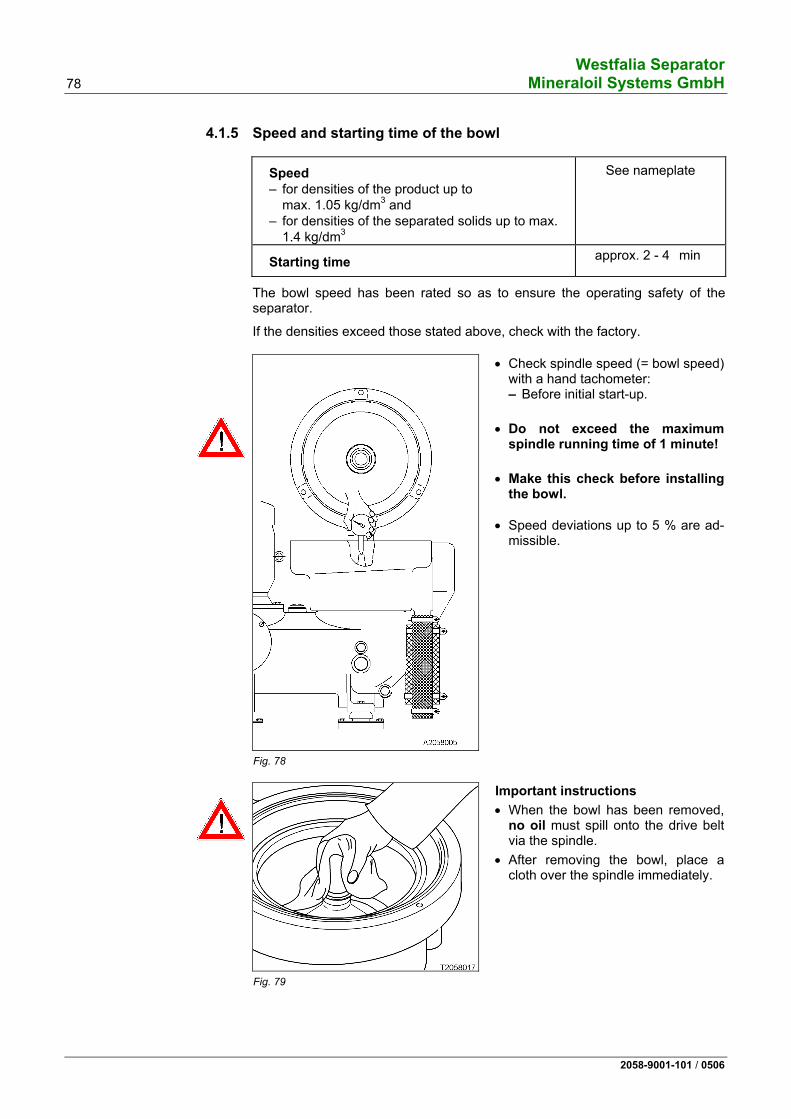
3.2.1 Before the first start-up • Check that
– the machine is correctly assembled. – the hoses and hose pipes are undamaged and connected (see section
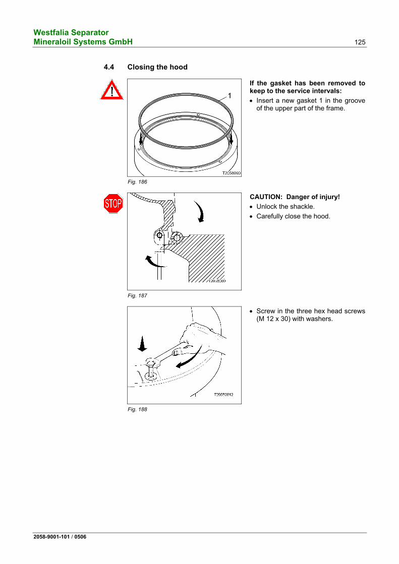
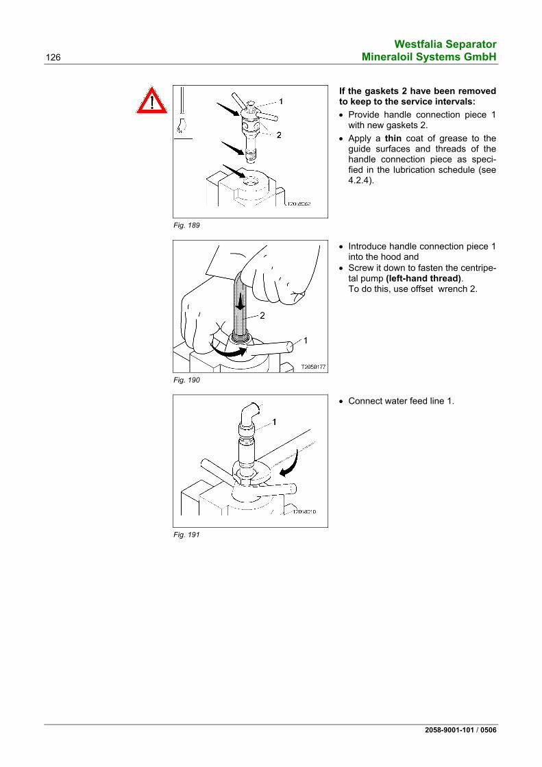
4.2.2). – the sight glass in the frame for observing the drive belt is clean. – the drive chamber is filled with oil in accordance with section 4.2.3. – the bowl height is correct (see section 4.7.1). – the brake is released by turning the handle clockwise. – the bowl can be rotated by hand. – the hex head screws on the hood are tight (see 4.4). – the handle connection piece is tightly bolted to the centripetal pump (see
4.4). – the feed and discharge lines are connected (see 4.4).
3.2.2 Before every start-up • Check that
– the machine is correctly assembled. – the hoses and hose pipes are undamaged and connected (see section
4.2.2). – the sight glass in the frame for observing the drive belt is clean. – the gear chamber is filled with oil as specified in section 4.2.3. – the brake is released by turning the handle clockwise. – the hex head screws on the hood are tight (see 4.4). – the handle connection piece is tightly bolted to the centripetal pump (see
4.4). – the feed and discharge lines are connected (see 4.4).
Westfalia Separator Mineraloil Systems GmbH 57
2058-9001-101 / 0506
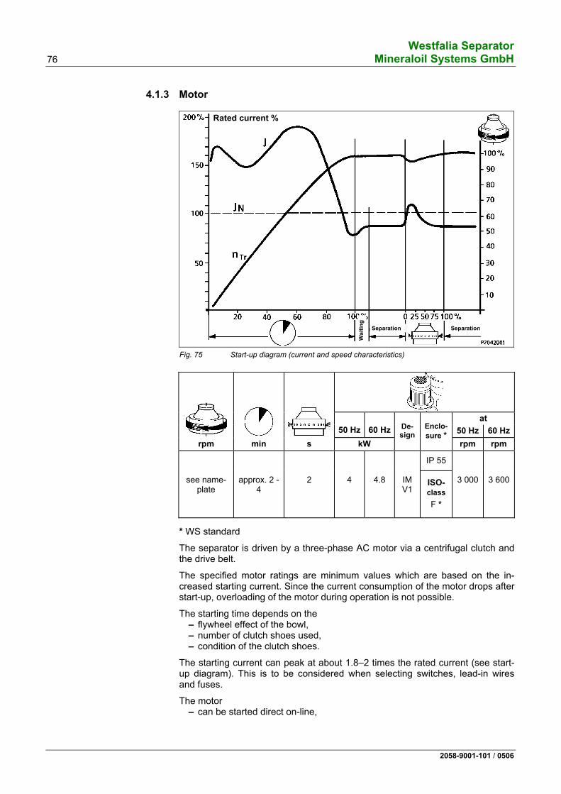
3.3 Starting the separator • See section 3.2.2.
• Open the shut-off valve in the product feed line.
• Switch on the motor. Compare the current and starting time with the diagram (section 4.1.3) until the bowl reaches the speed specified on the separator nameplate.
• Start the preheater (if installed) after switching on the motor!
• Open the stop valve in the product discharge.
• Switch on the control unit.
• Check that the operating mode selected on the control unit corresponds to the valve positioning in the system.
• Start the program.
• After the feed valves have automatically opened – set the backpressure in the product discharge to approx. 1.5 bar; – adjust the desired throughput; – when necessary, correct the backpressure in the product discharge.
• Check the discharges for solids and dirty water; there must be no oil flow!
3.4 Monitoring of operation The machine is monitored largely by the separator control.
Operations to be carried out regularly: • On your daily round, especially during the first 1500 operating hours, pay at-
tention to the following: – Oil level – Temperatures – Pressures – Leakage – Vibrations – Current consumption – Starting time – Hoses and hose pipes
• Keep to the maintenance schedule (see 4.2.1)!
• Inspection We recommend having the separator checked regularly by our specialists. These checks help to – maintain the operating safety of the machine and – avoid unplanned downtime.
Westfalia Separator 58 Mineraloil Systems GmbH
2058-9001-101 / 0506
3.5 Setting the separation time When using time-dependent automatic control programs, accurate setting of the separation time (time between ejection cycles) is only possible if the throughput capacity and solids loading in the feed remain constant. If this is not the case, it may be necessary to correct the settings during operation.
The separating time depends on • the preselected operating mode (partial or total ejection mode), • the solids loading in the feed, • the consistency of the solids, • the effective solids space volume in the bowl, • the separator throughput.
Given constant conditions, the separating time can be determined by calcula-tion.
The following times have proven appropriate in practice (examples):
Product Total ejection Partial ejection HFO 1 h to max. 2 h 0,5 h to max. 1 h MDO 2 h 1 h LO mild 2 h 1 h LO HD 1 h to max. 2 h 0,5 h to max. 1 h
3.5.1 Mathematical calculation Example for mathematical calculation of the separating time:
Given: Solids content (1) p = 0.05 % Solids holding space volume V = 0.9 l Solids holding space given 75 % utilisation V' = 0.6 l Throughput capacity (1) Vo = 1 000 l/h Wanted: Separating time t = ? min
The separating time to be set is calculated as follows:
V’ 0.6 t = ——— • 60 • 100 = —————— • 6 000 = 72 min = 1.2 h
V° • p 1 000 • 0.05
(1) Solids content and throughput capacity must be determined on site or taken from
the order specification.
Westfalia Separator Mineraloil Systems GmbH 59
2058-9001-101 / 0506
3.6 Ejecting the bowl
Automatic operation
• Initiate ejection program by pressing the key ”Program 1”:
– The product feed is closed. – Displacement – Bowl ejection – Speed recovery
• The product valve opens again.
Hand operation (in the case of unscheduled shut-down)
• Cut off the product feed to the separator:
– Close the product valve using the manual override.
• Eject the bowl:
– Open the operating liquid valve using the manual override for approx. 2 –3 seconds.
• Speed recovery
– Wait for approx. 20 – 30 seconds.
• Separating mode
– Open the product valve using the manual override.
Westfalia Separator 60 Mineraloil Systems GmbH
2058-9001-101 / 0506
3.7 Shutting down the separator • Switch off the preheater (if installed).
– Continue to feed product for a few minutes since the preheater continues to heat for a short time.
Automatic operation
• End the separation program with the key "program 0" – Two total ejections are performed automatically.
Hand operation (in the case of unscheduled shut-down)
• Close the product feed: – Close the product valve using the manual override.
• Eject the bowl: See section 3.6.
• Close the discharges.
• Close the feed for operating water, filling and displacement water.
• Switch off the motor.
• Switch off the product pump (if installed).
• Close the stop valve in the suction side of the product pump (if installed).
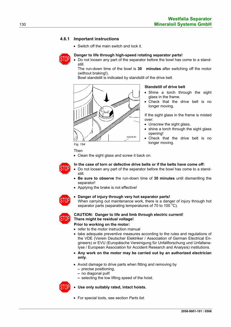
Danger to life through high-speed rotating separator parts! • Do not loosen any part of the separator before the bowl has come to a stand-
still. The run-down time of the bowl is 30 minutes after switching off the motor (without braking!). Bowl standstill is indicated by standstill of the drive belt.
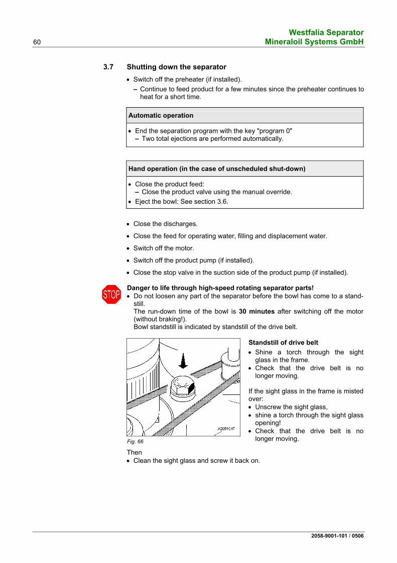
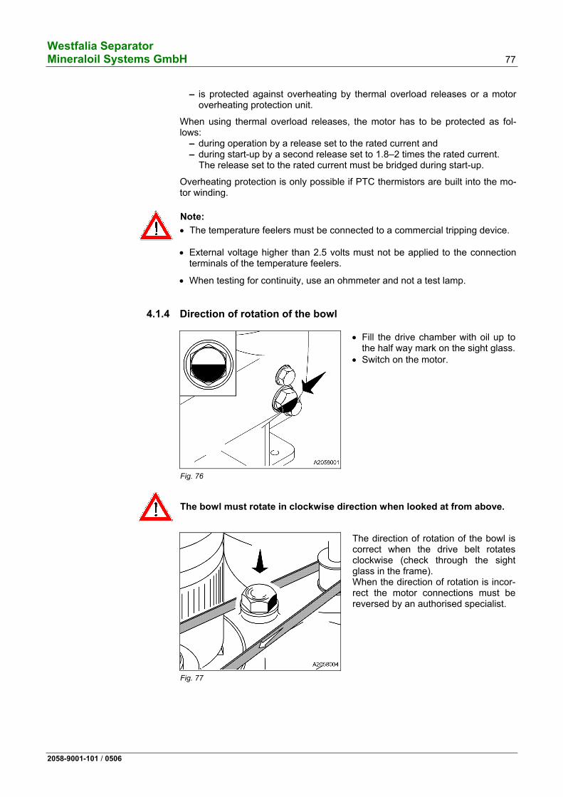
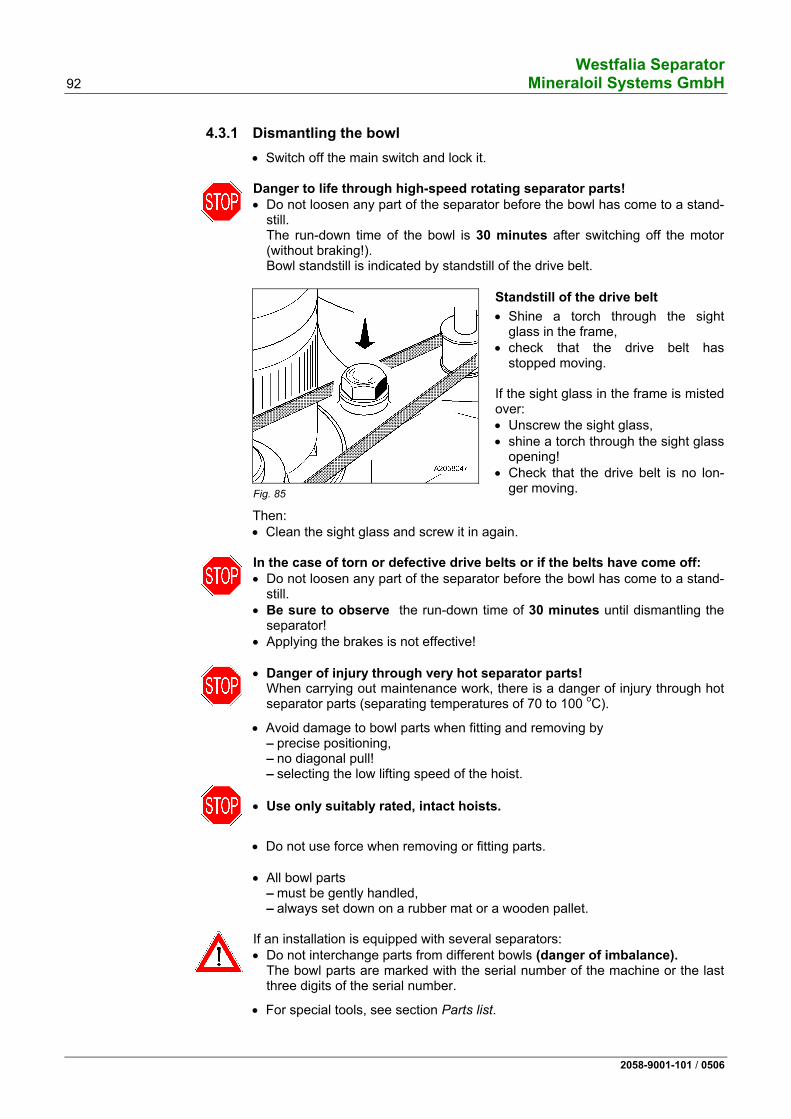
Fig. 66
Standstill of drive belt
• Shine a torch through the sight glass in the frame.
• Check that the drive belt is no longer moving.
If the sight glass in the frame is misted over: • Unscrew the sight glass, • shine a torch through the sight glass
opening! • Check that the drive belt is no
longer moving.
Then • Clean the sight glass and screw it back on.
Westfalia Separator Mineraloil Systems GmbH 61
2058-9001-101 / 0506
In the case of torn or defective drive belts or if the belts have come off: • Do not loosen any part of the separator before the bowl has come to a stand-
still. • Be sure to observe the run-down time of 30 minutes until dismantling the
separator! • Applying the brake is not effective!
• Danger of injury through very hot separator parts! When carrying out maintenance work, there is a danger of injury through hot separator parts (separating temperatures of 70 to 100 oC (158 – 212 oF).)
Westfalia Separator 62 Mineraloil Systems GmbH
2058-9001-101 / 0506
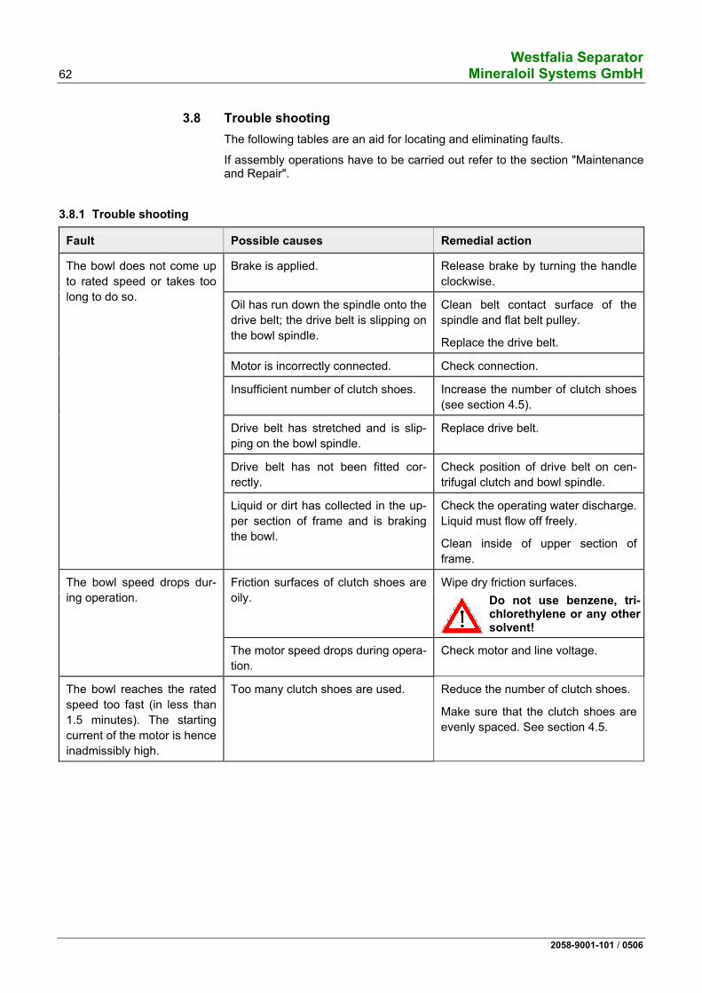
3.8 Trouble shooting The following tables are an aid for locating and eliminating faults.
If assembly operations have to be carried out refer to the section "Maintenance and Repair".
3.8.1 Trouble shooting
Fault Possible causes Remedial action
Brake is applied. Release brake by turning the handle clockwise.
Oil has run down the spindle onto the drive belt; the drive belt is slipping on the bowl spindle.
Clean belt contact surface of the spindle and flat belt pulley.
Replace the drive belt.
Motor is incorrectly connected. Check connection.
Insufficient number of clutch shoes. Increase the number of clutch shoes (see section 4.5).
Drive belt has stretched and is slip-ping on the bowl spindle.
Replace drive belt.
Drive belt has not been fitted cor-rectly.
Check position of drive belt on cen-trifugal clutch and bowl spindle.
The bowl does not come up to rated speed or takes too long to do so.
Liquid or dirt has collected in the up-per section of frame and is braking the bowl.
Check the operating water discharge. Liquid must flow off freely.
Clean inside of upper section of frame.
Wipe dry friction surfaces. Friction surfaces of clutch shoes are oily. Do not use benzene, tri-
chlorethylene or any other solvent!
The bowl speed drops dur-ing operation.
The motor speed drops during opera-tion.
Check motor and line voltage.
The bowl reaches the rated speed too fast (in less than 1.5 minutes). The starting current of the motor is hence inadmissibly high.
Too many clutch shoes are used. Reduce the number of clutch shoes.
Make sure that the clutch shoes are evenly spaced. See section 4.5.
Westfalia Separator Mineraloil Systems GmbH 63
2058-9001-101 / 0506
Fault Possible causes Remedial action
Bowl is out of balance for the follow-ing reasons:
For pos. 1 - 4: • Shut down separator. • Apply brake. • Close the product feed and dis-
charge. • Bowl must not be emptied as
otherwise the vibrations occurring during shut-down will intensify.
If bowl leaks, • Completely open the water sup-
ply.
1. The separated dirt has deposited unevenly in the bowl.
Clean bowl.
2. Bowl has not been correctly as-sembled or parts of different bowls (if plant has several separators) have been interchanged.
Assemble bowl properly.
3. The tension in the disk stack has slackened.
Check that the bowl lock ring is screwed on tight enough.
CAUTION: A loose lock ring can en-danger life!
Check number of disks.
4. Bowl parts are damaged. Send bowl to factory for repair.
Do not carry out your own repairs! Do not weld or solder as this would weaken the bowl!
Uneven run of the centri-fuge.
Ball bearings are worn. Replace damaged bearings.
ATTENTION! Use only the ball bearings specified in the parts list.
Dry dirt or rubber particles have de-posited: between the guides of the chamber
bottom and annular piston or - between annular piston and bowl
bottom or - between sliding piston and bowl
bottom.
Clean bowl parts.
Renew damaged gaskets.
Grease guides (see 4.2.4 - lubrica-tion schedule).
The closing chamber is dirty. Dismantle bowl.
Clean closing chamber.
The bowl does not open or not properly (cont.)
Gasket 2 of polyamide has a loose fit in the groove of the bowl top.
Product seeps into the gasket groove and presses the gasket out of the groove while the sliding piston moves downwards, so that there is no gap for solids ejection.
Replace polyamide gasket (see 4.3.8).
The bowl does not empty completely. Solids remain in the bowl.
The operating water capacity is too low.
Check line pressure and increase if necessary.
Operating water data: – Pressure 2 - 3 bar (with open
valve) – Volume flow min. 1 800 l/h (gauge
the capacity by litres) ≅ 1.0 l in 2 sec
Gasket 2 in the bowl top wears too quickly.
The product contains abrasive solids. Remove the abrasive solids by in-stalling a strainer.
The operating water in the closing chamber has diminished during a long separating time (evaporation etc.).
Set the operating water pulse and time (see manual of the control sys-tem).
The bowl opens during se-paration.
Time pulse for the operating water in-jection is too long.
Set the operating water pulse (see manual of the control system).
The bowl does not close or open properly after a long-term shut-down of the sepa-rator.
The bowl was not thoroughly cleaned before a long-term standstill of the separator. Scale has deposited and dried out. - between closing-chamber bottom
and annular piston or - between annular piston and bowl
bottom or - between sliding piston and bowl
bottom.
Before removing - the closing-chamber bottom, - the sliding piston and - the annular piston dislodge the dried-up scale with citric acid in the gaps - between closing-chamber bottom,
sliding piston and annular piston or
- between sliding piston and bowl bottom.
Dismantle and thoroughly clean the bowl.
The discharging product is not clean (bowl overflow).
Dirt of very high density has collected in the distributor neck (e.g. rust from tanks and lines). This partially blocks the feed which discharges as over-flow.
Clean the distributor neck.
Westfalia Separator 70 Mineraloil Systems GmbH
2058-9001-101 / 0506
Westfalia Separator Mineraloil Systems GmbH 71
2058-9001-101 / 0506
4 Installation - Maintenance - Repair
4.1 Installation of the separator ...............................................................72 4.1.1 Transporting the separator ....................................................................74 4.1.2 Installing the separator ..........................................................................75 4.1.3 Motor......................................................................................................76 4.1.4 Direction of rotation of the bowl .............................................................77 4.1.5 Speed and starting time of the bowl ......................................................78 4.2 Maintenance and lubrication..................................................................80 4.2.1 Maintenance schedule...........................................................................80 4.2.2 Hoses and hose pipes ...........................................................................83 4.2.3 Lubrication .............................................................................................84 4.2.4 Lubrication Chart ...................................................................................86 4.2.5 Table of lubricating oils ..........................................................................88 4.2.6 Comments on table of lubricating oils for separators from Westfalia
Separator ...............................................................................................89 4.3 Bowl .......................................................................................................90 4.3.1 Dismantling the bowl..............................................................................92 4.3.2 Cleaning the bowl ................................................................................102 4.3.3 Cleaning the frame ..............................................................................103 4.3.4 Cleaning the strainer and the operating water feeding system ...........103 4.3.5 Important instructions ..........................................................................104 4.3.6 Assembling the bowl............................................................................106 4.3.7 Replacing the polyamide gasket in the annular piston ........................119 4.3.8 Replacing the polyamide gasket (bowl top).........................................121 4.3.9 Reworking the sliding piston................................................................123 4.4 Closing the hood..................................................................................125 4.5 Motor and centrifugal clutch ................................................................127 4.6 Drive.....................................................................................................128 4.6.1 Important instructions ..........................................................................130 4.6.2 Removing the drive belt and spindle assembly ...................................132 4.6.3 Dismantling the spindle assembly .......................................................136 4.6.4 Removing the centrifugal clutch ..........................................................138 4.6.5 Fitting the spindle assembly ................................................................142 4.6.6 Fitting the centrifugal clutch.................................................................144 4.6.7 Fitting the motor...................................................................................149 4.7 Height adjustment................................................................................152 4.7.1 Bowl height ..........................................................................................152 4.7.2 Centripetal pump clearance.................................................................153 4.8 Final checks after assembling the separator .......................................155 4.9 Before a long-term shut-down of the separator ...................................155 4.10 Before restarting ..................................................................................156 4.11 Standard tools......................................................................................158
Westfalia Separator 72 Mineraloil Systems GmbH
2058-9001-101 / 0506
4.1 Installation of the separator
Fig. 70 Subject to modification – Refer to project-specific dimensioned drawing!
Solids discharge
Filling, displacement and operating water feed
Product discharge
Product feed
Solids discharge Water discharge
Operating water dicharge
Fastening the separator
Water dischargeOperating water discharge
Centre of gravity
These dimensions must be adhered to!
Do not discharge residuals into public waters!
• Refer to the installation guidelines for further information.
Westfalia Separator Mineraloil Systems GmbH 73
2058-9001-101 / 0506
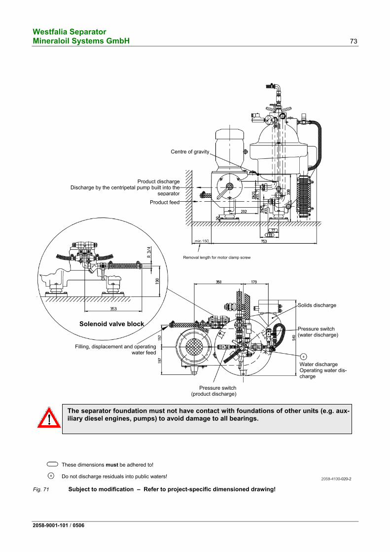
Fig. 71 Subject to modification – Refer to project-specific dimensioned drawing!
Water discharge Operating water dis-charge
Centre of gravity
Solids discharge
Filling, displacement and operatingwater feed
These dimensions must be adhered to!
Do not discharge residuals into public waters!
Product feed
Product dischargeDischarge by the centripetal pump built into the
separator
Pressure switch (water discharge)
Pressure switch(product discharge)
The separator foundation must not have contact with foundations of other units (e.g. aux-iliary diesel engines, pumps) to avoid damage to all bearings.
Solenoid valve block
Removal length for motor clamp screw
Westfalia Separator 74 Mineraloil Systems GmbH
2058-9001-101 / 0506
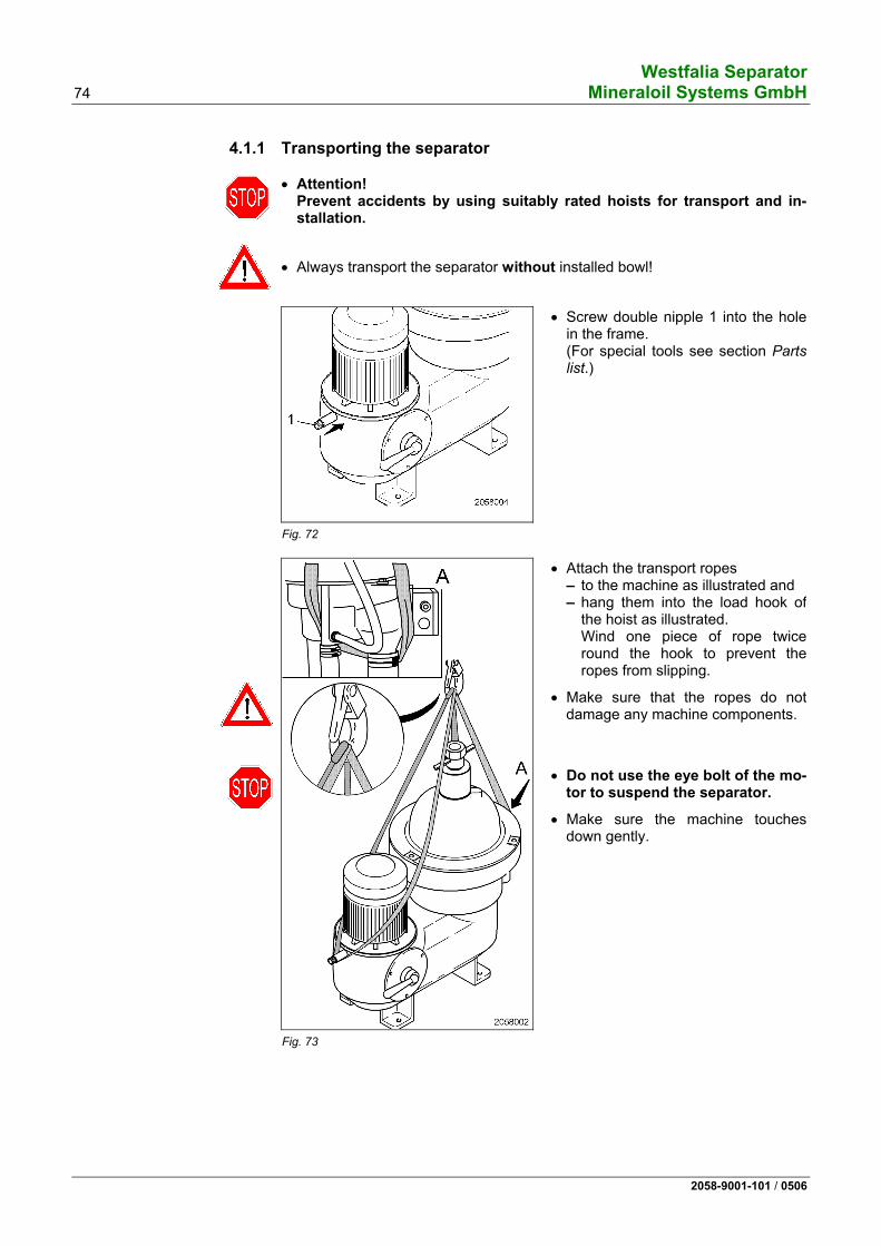
4.1.1 Transporting the separator
• Attention! Prevent accidents by using suitably rated hoists for transport and in-stallation.
• Always transport the separator without installed bowl!
Fig. 72
• Screw double nipple 1 into the hole in the frame. (For special tools see section Parts list.)
Fig. 73
• Attach the transport ropes – to the machine as illustrated and – hang them into the load hook of
the hoist as illustrated. Wind one piece of rope twice round the hook to prevent the ropes from slipping.
• Make sure that the ropes do not damage any machine components.
• Do not use the eye bolt of the mo-tor to suspend the separator.
• Make sure the machine touches down gently.
Westfalia Separator Mineraloil Systems GmbH 75
2058-9001-101 / 0506
4.1.2 Installing the separator • Before erecting the separator make sure that
– sufficient space is available for operating and dismantling the machine.
– the foundation is not connected to foundations of other vibrating units to avoid the transfer of vibrations.
Fig. 74
• Align separator 1 with machine feet 2 and plates 3 on foundation 4.
• Tack plates 3.
• Undo screws 5.
• Lift off separator with feet (see sec-tion 4.1.1).
• Weld plates 3 to foundation 4.
• Place the separator on plates 3 and• bolt tight with hex head screws 5.
• Firmly tighten hex head screws 6.
Westfalia Separator 76 Mineraloil Systems GmbH
2058-9001-101 / 0506
4.1.3 Motor
Rated current %
Separation Separation
Wai
ting
Fig. 75 Start-up diagram (current and speed characteristics)
at
50 Hz 60 Hz 50 Hz 60 Hzrpm min s kW
De-sign
Enclo-sure *
rpm rpm
IP 55
see name-plate
approx. 2 - 4
2 4 4.8 IM V1
ISO-class F *
3 000 3 600
* WS standard
The separator is driven by a three-phase AC motor via a centrifugal clutch and the drive belt.
The specified motor ratings are minimum values which are based on the in-creased starting current. Since the current consumption of the motor drops after start-up, overloading of the motor during operation is not possible.
The starting time depends on the – flywheel effect of the bowl, – number of clutch shoes used, – condition of the clutch shoes.
The starting current can peak at about 1.8–2 times the rated current (see start-up diagram). This is to be considered when selecting switches, lead-in wires and fuses.
The motor – can be started direct on-line,
Westfalia Separator Mineraloil Systems GmbH 77
2058-9001-101 / 0506
– is protected against overheating by thermal overload releases or a motor overheating protection unit.
When using thermal overload releases, the motor has to be protected as fol-lows:
– during operation by a release set to the rated current and – during start-up by a second release set to 1.8–2 times the rated current.
The release set to the rated current must be bridged during start-up.
Overheating protection is only possible if PTC thermistors are built into the mo-tor winding.
Note:
• The temperature feelers must be connected to a commercial tripping device.
• External voltage higher than 2.5 volts must not be applied to the connection terminals of the temperature feelers.
• When testing for continuity, use an ohmmeter and not a test lamp.
4.1.4 Direction of rotation of the bowl
Fig. 76
• Fill the drive chamber with oil up to the half way mark on the sight glass.
• Switch on the motor.
The bowl must rotate in clockwise direction when looked at from above.
Fig. 77
The direction of rotation of the bowl is correct when the drive belt rotates clockwise (check through the sight glass in the frame). When the direction of rotation is incor-rect the motor connections must be reversed by an authorised specialist.
Westfalia Separator 78 Mineraloil Systems GmbH
2058-9001-101 / 0506
4.1.5 Speed and starting time of the bowl
Speed – for densities of the product up to
max. 1.05 kg/dm3 and – for densities of the separated solids up to max.
1.4 kg/dm3
See nameplate
Starting time approx. 2 - 4 min
The bowl speed has been rated so as to ensure the operating safety of the separator.
If the densities exceed those stated above, check with the factory.
Fig. 78
• Check spindle speed (= bowl speed) with a hand tachometer: – Before initial start-up.
• Do not exceed the maximum
spindle running time of 1 minute!
• Make this check before installing the bowl.
• Speed deviations up to 5 % are ad-
missible.
Fig. 79
Important instructions
• When the bowl has been removed, no oil must spill onto the drive belt via the spindle.
• After removing the bowl, place a cloth over the spindle immediately.
Westfalia Separator Mineraloil Systems GmbH 79
2058-9001-101 / 0506
Westfalia Separator 80 Mineraloil Systems GmbH
2058-9001-101 / 0506
4.2 Maintenance and lubrication
• Special care must be taken when performing maintenance and lubrication operations. Conscientiously performed maintenance and lubrication operations improve the service life ofthe separator.
• In the case of accessories (motor, product pump, preheater, solenoid valve block etc.) the manu-facturer’s maintenance and lubrication instructions must be observed.
4.2.1 Maintenance schedule
Operations Remark Maintenance(1)
after operating
hours at the latest
after
To assure correct functioning and operating safety, • in case of non-routine shut-down, see section 3.7 - manual operation. • pay attention to the following points during servicing:
– Oil level – Leakage – Starting time – Temperatures – Vibrations – Hoses and hose pipes – Pressures – Current consumption lines (see 4.2.2)
• Before assembling, grease the guide and contact surfaces of the main bowl components.(2) • in the case of frequent starting and stopping of the separator, shaft-driven alternator operation
and in power plants, the condition of the clutch shoes must be checked more often than stated in this schedule. It is not possible to state a definitive time. We recommend checking the clutch shoes after 1000 operating hours or after 2 months at the latest.
Bowl inspection • Dismantle bowl and centripetal pump. • Clean the bowl and centripetal pump parts
and check for corrosion and erosion. • Clean all holes, nozzles and chambers of
the hydraulic system. • The cones of bowl and spindle must be
clean and dry when fitting. Replace gaskets (bowl and hood). • Use set of spare parts "bowl/hood“ (opera-
tion: 1 year or 8000 hours). See section Parts list.
Re-lubricate motor bearings (if required) • See instructions of motor manufacturer Oil change and thorough cleaning of the drive chamber.
When using mineral oil (3)
Clean the strainer and pipe in the operating liq-uid feed system on the self-cleaning separator.
• See section 4.3.4.
Clean the strainer at the water pressure reducer (if installed).
Clean filter in suction line of product pump (if in-stalled).
Clean the sight glass in the frame for observing the drive belt.
4 000 12 000 20 000 28 000 36 000 44 000
1/2 years 1 1/2 years 2 1/2 years 3 1/2 years 4 1/2 years 5 1/2 years
Check the hoses and hose pipes and replace when necessary.
Westfalia Separator Mineraloil Systems GmbH 81
2058-9001-101 / 0506
Maintenance(1)
after operating
hours
at the latest after
Operations Remark
Bowl inspection • Dismantle bowl and centripetal pump. • Clean the bowl and centripetal pump parts
and check for corrosion and erosion. • Clean all holes, nozzles and chambers of
the hydraulic system. • The cones of bowl and spindle must be
clean and dry when fitting. • Use set of spare parts "bowl/hood“ (opera-
tion: 1 year or 8000 hours). See section Parts list.
Replace gaskets (bowl and hood).
• Replace only the damaged polyamide gasket 60 (see sec-tion 4.3.7)!
Clean the inside of the upper section of frame. • Remove bowl. Replace gaskets and retaining ring (see page 201). Replace the drive belt. Replace spindle ball bearings. Replace vibration absorber.
• Use set of spare parts "drive" (operation: 1 year or 8000 hours). See section Parts list.
h: min. 18 mm
Check thickness of the clutch shoes(4) and replace if necessary.
New clutch shoe: h = 26 mm Check thickness of brake lining. Re-lubricate motor bearings (if required) • See instructions of motor manufacturer
When using mineral oil (3) Oil change and thorough cleaning of the drive chamber. When using synthetic oil (3)
Check the bowl height. • See section 4.7.1. In case of direct current Check the spindle speed (bowl).
• Check only after motor or drive replace-ment.
• See section 4.1.5. Check the starting time. • See section 4.1.5. Clean the strainer and pipe in the operating liquid feed system on the self-cleaning separator.
• See section 4.3.4
Clean the strainer at the water pressure reducer (if installed).
Clean filter in suction line of product pump (if in-stalled).
Clean the sight glass in the frame for observing the drive belt.
8 000 24 000 40 000
1 year 3 years 5 years
Check the hoses and hose pipes and replace when necessary.
(1) The specified maintenance intervals are recommendations which apply only for normal conditions. Negative operating conditions (e.g. low-grade fuel, excessively high temperature, strong vibrations, frequent starting and stopping of the separator etc.) can necessitate shorter maintenance intervals.
(2) see section 4.2.4 - Lubrication schedule (3) see section 4.2.3 - Oil quality and oil change (4) In the case of frequent starting and stopping of the separator, shaft-driven alternator operation and power plants shorter maintenance
intervals are required It is not possible to state a definitive time. We recommend checking the clutch shoes after 1,000 operating hours or after 2 months at the latest.
Westfalia Separator 82 Mineraloil Systems GmbH
2058-9001-101 / 0506
Maintenance(1)
after operating
hours
at the latest after
Operations Remark
Bowl inspection • Dismantle bowl and centripetal pump. • Clean the bowl and centripetal pump
parts and check for corrosion and ero-sion.
• Clean all holes, nozzles and chambers of the hydraulic system.
• The cones of bowl and spindle must be clean and dry when fitting.
• Use set of spare parts "bowl/hood“ (op-eration: 1 year or 8000 hours). See sec-tion Parts list.
Replace gaskets (bowl and hood).
• Replace only the damaged polyamide gasket 60 (see sec-tion 4.3.7)!
Clean the inside of the upper section of frame. • Remove bowl. Replace gaskets and retaining ring (see page 203). Replace the drive belt. Check thickness of the clutch shoes (4) and replace when
h smaller than 18 mm.
New clutch shoe: h = 26 mm Replace spindle ball bearings. Replace ball bearings of centrifugal clutch. Replace vibration absorber. Check thickness of brake lining and replace if necessary.
• Use set of spare parts "drive" (operation: 2 years or 16000 hours). See section Parts list.
Re-lubricate motor bearings (if required) • See instructions of motor manufacturer When using mineral oil (3) Oil change and
thorough cleaning of the drive chamber. When using synthetic oil (3)
Check the bowl height. • See section 4.7.1. In case of direct current Check the spindle speed (bowl).
• Check only after motor or drive replace-ment.
• See section 4.1.5. In case of three-phase current: Check the spindle speed (bowl).
• Check only after drive replacement. • See section 4.1.5.
Check the starting time. • See section 4.1.5. Clean the strainer and pipe in the operating liquid feed system on the self-cleaning separator.
• See section 4.3.4.
Clean the strainer at the water pressure reducer (if installed).
Clean filter in suction line of product pump (if in-stalled).
Clean the sight glass in the frame for observing the drive belt.
16 000 32 000 48 000
2 years 4 years 6 years
Check the hoses and hose pipes and replace when necessary.
Westfalia Separator Mineraloil Systems GmbH 83
2058-9001-101 / 0506
Maintenance(1)
after operating
hours at the latest
after Operations Remark
48 000 6 years Equip the machines with new vibration isolators. We recommend having the machines checked by a WS service engineer.
Legend: (1) = The specified maintenance intervals are recommendations which apply only for normal conditions.
Negative operating conditions (e.g. low-grade fuel, excessively high temperature, strong vibrations, frequent starting and stopping of the separator etc.) can necessitate shorter maintenance intervals.
(2) = see section 4.2.4 - Lubrication schedule (3) = see section 4.2.3 - Oil quality and oil change (4) = In the case of frequent starting and stopping of the separator, shaft-driven alternator operation and power plants shorter mainte-
nance intervals are required. It is not possible to state a definitive time. We recommend checking the clutch shoes after 1,000 oper-ating hours or after 2 months at the latest.
4.2.2 Hoses and hose pipes Replace hose pipes when an inspection reveals one or more of the following de-fects: • Damage of the outer layer down to the fabric (e. g. chafe marks, cuts or
cracks). • Leaky spots. • Damage to or deformation of the hose fittings.
(Slight surface damage is not a reason for replacement.) • The hose becomes dislodged from the fitting. • Corrosion of the fitting diminishing function and strength.
Fig. 80
Protective hose 1 • Fit the protective hoses at all con-
tact points to the separator.
• Fit the protective tube along the en-tire length of the cable tree (contact points to the machine).
• Adapt the length of the protective hose.
Westfalia Separator 84 Mineraloil Systems GmbH
2058-9001-101 / 0506
4.2.3 Lubrication The spindle bearings are splash-lubricated from a central oil bath.
MOTOR BEARINGS
For re-greasing the motor bearings, refer to the instructions of the motor manu-facturer.
OIL QUALITY (mineral oil)
The mineral gear oil tested by Westfalia Separator with the designation "Separa-tor lube oil CLP 100" meets the requirements and should preferably be used.
Part-No. 0015-0003-080 (2.5 litres) Dispose of the oil as per instructions of the oil manufacturer.
The viscosity class SAE 30 covers a larger viscosity range than specified here. However, only oils with the viscosity range specified here may be used.
Do not use mineral motor vehicle or engine oils.
OIL QUALITY (synthetic oil)
Use the synthetic lube oil tested by Westfalia Separator!
Designation according to ISO
Mobil SHC 626
Viscosity class (ISO) VG 68 Viscosity - at 40 oC (104 oF) 65 mm2/s - at 100 oC (212 oF) 10.4 mm2/s Viscosity index (VI) 147
Density (at 15 oC/59 oF) 0.857 g/ml
based on Polyalphaolefin
Part-No. 0015-0020-010 (1 litre) Dispose of the oil as per instructions of the oil manufacturer.
Do not use mineral motor vehicle or engine oils.
Westfalia Separator Mineraloil Systems GmbH 85
2058-9001-101 / 0506
OIL QUANTITY
IMPORTANT: Do not forget to top up the oil in good time!
Fig. 81
Filling in oil
Fill the drive with oil before commis-sioning the separator.
• Unscrew the screw plug and • fill in oil through the charge hole.
Filling quantity approx. 2.5 litres
Fig. 82
Oil level IMPORTANT: • Check the oil level only when the
separator is at standstill. • The oil level must never drop below
the lower third of the sight glass dur-ing operation.
1 Maximum oil level 2 Minimum oil level
Minimum oil level (at separator standstill)
approx. up to lower third of sight glass
Maximum oil level (at separator standstill)
up to middle of sight glass
OIL CHECK
• Check the oil level every week!
• From time to time undo the oil drain screw and check whether there is water in the oil bath. When the oil exhibits a milky colouring (emulsification), the oil must be changed immediately.
OIL CHANGE
• Change oil after about – 4000 operating hours or 6 months at the latest (mineral oil). – 8000 operating hours or 1 year at the latest (synthetic oil).
• Clean sight glass.
Westfalia Separator 86 Mineraloil Systems GmbH
2058-9001-101 / 0506
4.2.4 Lubrication Chart
Fig. 83 Lubrication schedule
Westfalia Separator Mineraloil Systems GmbH 87
2058-9001-101 / 0506
Lubricant Lubrication frequency Lubricat-ing point
Designation Designation after
operating hours
per year
Amount of lu-bricant Lubrication point
DIN 51502
CLP 100
Lube oil (mineral)
CC 100 ISO 3498
4 000 2 x 2 500 cm3 Drive chamber
1
Lube oil (synthetic)
Mobil SHC 626 ISO VG 68 8 000 1 x 2 500 cm3 Drive chamber
2 according to instructions of motor manufacturer Motor bearings
3 2 x Threads and sliding sur-faces of bowl
4 1 x Threads of fittings
5
Lubricating grease
see parts list as required
1 x
apply sparingly
Manually-operated parts such as locking brake
• Check oil level regularly through sight glass. • Manual lubrication • Refer to lubricating oil table in section 4.2.5!
Westfalia Separator 88 Mineraloil Systems GmbH
2058-9001-101 / 0506
4.2.5 Table of lubricating oils
Lubricating oil sorts suggested by some firms
Viscosity at 40 °C (104 °F) Manufac-
turer Designation mm2/s (cSt)
BLASIA 100
Westfalia Separator
Lubricating oil table for separators in onshore and shipboard opera-tion RADULA 100
DIESEL GAMMA 30
100
Separator Lube oil
ATLANTA MARINE 30 Viscosity DISOLA M 3015 105
MONTANOL HK 100 100
ENERGOL GR-XP 100 100 ENERGOL DL-MP 30 114
Oil
fillin
g
Kinematic viscosity at 40 °C (104 °F)
Type
l
Sym
bol
(Des
igna
tion
acco
rd-
ing
to D
IN 5
1502
)
mm2/s (cSt) HYSPIN AWS 100
BTC 3 ALPHA ZN 100 100
CTC 1 MARINE HEAVY 99 CTC 3
MTC 3 GST OIL 100 OTC 2 NL Gear Compound 100 100
OTC 3 Veritas Marine Oil R&O 30 108 WTC 2
1,3
DELO 3000 Marine Oil 30 104
ATLANTA MARINE 30
CSD 1 DISOLA M 3015 105
OSD 2 TURBINE T 100 95 SD 1
1,3
EXX-MAR XP 110 NUTO H 100 SPARTAN EP 100 100
ESD 18 HARMONY 100 95 GSC 15 VERITAS 30 110 OSD 6
GULF
OSD 18 HIDRAOIL HD 70 95 WSD 18
2,5
MOBILGARD 312 106 GARDINIA OIL 30 104
GSC 25 ROTELLA MX SAE 30 105 OSD 20 OSD 25
OSD 30 HYDRA WAY HMA 100 OSD 35 LOAD WAY EP 100 100
WSD 35
3,7
DORO AR SAE 30 119 TARO XD SAE 30 105
OSD 50
OSD 60 SD 50 WSD 60
5,0
CLP 100
90 to 110
0015-0003-080 (2.5 l)
Westfalia Separator Mineraloil Systems GmbH 89
2058-9001-101 / 0506
4.2.6 Comments on table of lubricating oils for separators from Westfalia Separator
Faultless functioning of separators very much depends on the proper type of lubricating oil used, since a high grade oil, selected to meet all service requirements, will minimize the wear, thus extending the ser-vice life and increasing the operating safety. For the lubrication of our separators we recommend to use the oils specified by us since continuous qual-ity checks are performed by Westfalia Separator. Oils proposed from some firms are not subjected to these tests. Therefore, Westfalia Separator cannot give a performance guarantee for those oils. Be sure to select only high grade solvent refined products. The specified oil types meet the requirements according to DIN. Under unfavourable operating condi-tions, e.g. high temperatures, the quality of the oils may be insufficient so that more efficient oils, e.g. synthetic oils, must be used. If necessary, consult Westfalia Separator. For the different separator types and oil types the viscosity ranges are specified in the table of lubricating oils. The operating temperature of the separator exceeds normally 80 oC (176 oF). At those temperatures some oils age quickly, so that they have to be changed prematurely. Be sure not to use lubricating oils with viscosities lower than those specified in the table. Due to the pos-sibility of the oil film breaking down, oil of too low a viscosity will give insufficient lubrication, resulting in increased wear. However, oils with a slightly higher viscosity than specified may be used. Bear in mind that the viscosity groups SAE 30, 40 and 50 (SAE = Society of Automotive Engineers) cover larger viscosity ranges and be sure to select lubricating oils with viscosities not lower than the minimum values of the viscosity ranges restricted for the different separator types.
Westfalia Separator 90 Mineraloil Systems GmbH
2058-9001-101 / 0506
4.3 Bowl
Fig. 84 Exploded view of the bowl and centripetal pump
100 Gasket 110 Gasket 120 Allen screw M 8 x 20 130 (1) Water chamber bottom 140 Gasket 150 Sliding piston 160 Gasket 170 Gasket 180 (1) Distributor, complete 190 Disk stack, complete 200 (1) Separating disk 210 (1) Bowl top 220 Gasket 230 Gasket 240 Threaded pin M 10 x 10 250 Centripetal pump chamber cover 260 Gasket 270 Gasket 280 Set of regulating rings 290 Gasket 300 Centripetal pump chamber cover 310 Lock ring 320 Spindle screw 330 Gasket 510 Centripetal pump, compl. 520 Gasket 530 Sensing liquid pump 540 Gasket 550 Gasket 560 Spacer ring 570 Gasket
(1) ATTENTION! After replacing this part, the complete bowl must be rebal-anced.
Westfalia Separator 92 Mineraloil Systems GmbH
2058-9001-101 / 0506
4.3.1 Dismantling the bowl • Switch off the main switch and lock it.
Danger to life through high-speed rotating separator parts! • Do not loosen any part of the separator before the bowl has come to a stand-
still. The run-down time of the bowl is 30 minutes after switching off the motor (without braking!). Bowl standstill is indicated by standstill of the drive belt.
Fig. 85
Standstill of the drive belt
• Shine a torch through the sight glass in the frame,
• check that the drive belt has stopped moving.
If the sight glass in the frame is misted over: • Unscrew the sight glass, • shine a torch through the sight glass
opening! • Check that the drive belt is no lon-
ger moving.
Then: • Clean the sight glass and screw it in again.
In the case of torn or defective drive belts or if the belts have come off: • Do not loosen any part of the separator before the bowl has come to a stand-
still. • Be sure to observe the run-down time of 30 minutes until dismantling the
separator! • Applying the brakes is not effective!
• Danger of injury through very hot separator parts! When carrying out maintenance work, there is a danger of injury through hot separator parts (separating temperatures of 70 to 100 oC).
• Avoid damage to bowl parts when fitting and removing by – precise positioning,
– no diagonal pull! – selecting the low lifting speed of the hoist.
• Use only suitably rated, intact hoists.
• Do not use force when removing or fitting parts.
• All bowl parts – must be gently handled, – always set down on a rubber mat or a wooden pallet.
If an installation is equipped with several separators: • Do not interchange parts from different bowls (danger of imbalance).
The bowl parts are marked with the serial number of the machine or the last three digits of the serial number.
• For special tools, see section Parts list.
Westfalia Separator Mineraloil Systems GmbH 93
2058-9001-101 / 0506
• For standard tools, see section 4.11.
Fig. 86
• Disconnect water feed line 1.
Fig. 87
• Unscrew handle connection piece 1 (left-hand thread) while holding
• the centripetal pump with offset wrench 2.
Fig. 88
• Unscrew the hex head screws with washers.
Westfalia Separator 94 Mineraloil Systems GmbH
2058-9001-101 / 0506
Fig. 89
• Hinge up hood. Danger of injury by incorrect hing-ing up of the hood! • The stirrup must register properly.
Fig. 90
If necessary (see sect. 4.2.1):
• Take gasket 1 out of the upper sec-tion of the frame.
Fig. 91
• Unscrew the lock ring with the hook wrench (left-hand thread) and
• remove it.
Fig. 92
• Screw handle connection piece into the centripetal pump (left-hand thread).
• Lift off the complete centripetal pump, centripetal pump chamber cover and spacer ring.
Westfalia Separator Mineraloil Systems GmbH 95
2058-9001-101 / 0506
Fig. 93
• Insert the pressure piece into the spacer ring 1.
• Pull off the spacer ring with fitted gaskets with the aid of a commercial puller.
Fig. 94
• Remove the following parts: – centripetal pump 1 with inserted
with gaskets 4 and 6, – centripetal pump 7 with inserted
gasket.
Fig. 95
• Unscrew the spindle screw – with a socket wrench and – commercially available ratchet
(left-hand thread).
Fig. 96
• Force the bowl – at least 10 mm off the spindle
cone using an eye bolt and – lift it out of the frame using a hoist.
Westfalia Separator 96 Mineraloil Systems GmbH
2058-9001-101 / 0506
Fig. 97
• Place a cloth over the spindle. When the bowl has been removed, no oil must spill onto the drive belt via the spindle.
Fig. 98
• Place on plate and • screw the complete eye bolt into the
bowl bottom.
Fig. 99
• Compress the disk stack.
Fig. 100
• Unscrew the threaded pins out of the bowl top with a screwdriver.
Westfalia Separator Mineraloil Systems GmbH 97
2058-9001-101 / 0506
Fig. 101
• Bolt ring spanner 1 to the bowl top.
• Make sure that the "O" mark is not covered by the ring spanner.
• Firmly tighten the fastening screws 2 of the ring spanner.
Fig. 102
• Strike open the bowl top with a mal-let (left-hand thread).
Fig. 103
• Unscrew the complete eye bolt from the bowl bottom.
• Remove the plate.
• Unscrew the ring spanner.
Fig. 104
• Lift off the bowl top with fitted gas-kets by hand.
Westfalia Separator 98 Mineraloil Systems GmbH
2058-9001-101 / 0506
Fig. 105
• Remove separating disk.
Fig. 106
• Lift out the distributor together with disk stack.
Fig. 107
• Insert the spindle screw.
Fig. 108
• Screw the complete eye bolt into the bell-shaped piece as shown.
• Screw the bell-shaped piece with eye bolt into the thread of the sliding piston.
Westfalia Separator Mineraloil Systems GmbH 99
2058-9001-101 / 0506
Fig. 109
• Force off the sliding piston with the aid of the eye bolt.
Fig. 110
• Remove the sliding piston (with fit-ted gasket) with bell-shaped piece and eye bolt.
Fig. 111
• Unscrew the four Allen screws hold-ing the closing-chamber bottom and the bowl bottom together.
Fig. 112
• Screw the complete eye bolt into the bell-shaped piece as shown.
• Screw the bell-shaped piece into the thread of the annular piston.
• Force off annular piston and closing chamber with the aid of the eye bolt.
Westfalia Separator 100 Mineraloil Systems GmbH
2058-9001-101 / 0506
Fig. 113
• Remove the annular piston and closing chamber bottom (with fitted gaskets) with the bell-shaped piece and eye bolt.
Fig. 114
• Unscrew the eye bolt and bell-shaped piece from the annular pis-ton.
Fig. 115
• Unscrew the spindle screw.
Fig. 116
• Remove gasket 1.
Westfalia Separator Mineraloil Systems GmbH 101
2058-9001-101 / 0506
Fig. 117
• Drive annular piston 1 and closing-chamber bottom 2 apart using a mallet.
Fig. 118
When replacing the gasket in the water chamber bottom:
• Turn bowl through 180o (upside down).
• Unscrew the four Allen screws from the water chamber bottom.
Fig. 119
• Water chamber bottom: – press off with a screwdriver and – remove it together with the gasket.
Westfalia Separator 102 Mineraloil Systems GmbH
2058-9001-101 / 0506
4.3.2 Cleaning the bowl It is generally not necessary to dismantle self-cleaning bowls for cleaning after separation unless
– the nature of the product makes it necessary, – the separator is to be shut down for a lengthy period (see section 4.9).
• Dismantle and clean the bowl for checking from time to time. See section 4.2.1 - Maintenance schedule.
• Use only a cleaning agent that is approved for the field of application!
• Do not use acid or chloric cleaning agents. Chlorine attacks stainless steel parts.
• Dissolve dried scale with citric acid.
• For cleaning the individual disks and bowl parts Do not use metal scrapers and metal brushes!
Fig. 120
• Take the gaskets out of the bowl parts.
• Clean the grooves and gaskets to avoid corrosion in the grooves.
• Replace damaged, very swollen, hardened or brittle gaskets immedi-ately.
• Clean the small holes for the feed and discharge of the operating liquid with particular care to ensure trouble-free bowl ejections.
Fig. 121
• Clean the distributor between the ribs with the brush on the inside and outside. When the distributor neck is very dirty, the feed clogs which can cau-se overflow.
• Apply a thin coat of grease to the guide surfaces and threads of the bowl parts after drying (see 4.2.4 Lubrication schedule).
• Reassemble the bowl immediately after cleaning.
Westfalia Separator Mineraloil Systems GmbH 103
2058-9001-101 / 0506
4.3.3 Cleaning the frame
Danger to life through electrical components! • Never rinse off the motor with a direct water jet.
• Use only approved cleaning agents, preferably a neutral cleaning agent, ben-zene or diesel oil.
• Do not use chloric cleaning agents. Chlorine attacks stainless steel parts.
• Dissolve dried scale with citric acid.
• Clean the inside of the upper section of the frame from time to time: – Refer to the maintenance schedule (section 4.2.1), – dismantle the bowl (section 4.3.1).
Fig. 122
• Place a cloth over the spindle.
When the bowl has been removed, no cleaning liquid must spill onto the drive belt via the spindle.
4.3.4 Cleaning the strainer and the operating water feeding system • The strainer and the operating water feeding system must be cleaned de-
pending on the quality of the operating water and overall load. See section 4.2.1 - Maintenance schedule.
• Use citric acid in case of furring.
• Thoroughly clean the parts with water.
Westfalia Separator 104 Mineraloil Systems GmbH
2058-9001-101 / 0506
4.3.5 Important instructions
CAUTION: Danger of imbalance! When the bowl has not been correctly assembled or is inadequately cleaned, forces can be produced in the high-speed rotating bowl which endanger the op-erating safety of the separator!
Therefore, the cleaning instructions (section 4.3.2) and assembling instructions (section 4.3.6) must be exactly followed.
Pay particular attention to the following:
• Before assembling the bowl, check to be sure that the guide and contact sur-faces of the bowl are clean.
• Grease the guide surfaces as specified in the lubrication schedule (see 4.2.4).
Fig. 123
• When fitting the bowl parts, make sure that the "O" marks on all parts are aligned. (Only then will the parts fit correctly over arresting pins and guide ribs).
• Avoid damaging bowl parts when fitting and removing by – precise positioning, – no diagonal pull! – Select the low lifting speed of the hoist.
• Use only suitably rated, intact hoists.
• Do not use force when fitting or removing parts.
Fig. 124
• If the plant has several separators, be sure not to interchange parts of different bowls (danger of imbal-ance).
The parts are marked – with the serial number or – the last three digits of the serial
number.
Westfalia Separator Mineraloil Systems GmbH 105
2058-9001-101 / 0506
Fig. 125
• Thoroughly clean the gasket grooves of the individual bowl parts and apply a thin coat of grease.
• After fitting check that – the gaskets are not twisted, – the gaskets are evenly positioned
in the groove.
• For special tools see section Parts list.
• For standard tools see section 4.11.
Westfalia Separator 106 Mineraloil Systems GmbH
2058-9001-101 / 0506
4.3.6 Assembling the bowl
• Pay special attention to sections 4.3.2 and 4.3.5
• For dimensions of the parts see 4.3 - exploded view.
15 Nm
Fig. 126
When replacing the gasket in the water chamber bottom:
• Insert gasket 1 in the groove of the water chamber bottom 2.
• Turn bowl bottom through 180o (up-side down).
• Place water chamber bottom 2 on the bowl bottom.
• The "O" marks must be aligned.
• Screw in the four Allen screws 3 holding the water chamber bottom and bowl bottom together tight. Torque: 15 Nm
Fig. 127
• Insert gasket 1 in the groove in the bowl bottom.
Westfalia Separator Mineraloil Systems GmbH 107
2058-9001-101 / 0506
Fig. 128
• For replacing the polyamide gasket 1 see section 4.3.7.
• Insert gasket 2 in the annular piston.
• Grease guide surfaces as specified in the lubrication schedule (see 4.2.4).
Fig. 129
• Install annular piston 1 in the bowl bottom 2.
Fig. 130
• Turn the sliding piston through 180o
(upside down).
• Fit sliding piston 1 together with plate 2 and complete eye bolt 3 as shown.
Fig. 131
• Press the annular piston 1 into the bowl bottom with the aid of nut 2.
Westfalia Separator 108 Mineraloil Systems GmbH
2058-9001-101 / 0506
Fig. 132
• Unscrew complete eye bolt 1.
• Remove plate 2 and sliding piston 3.
Fig. 133
• Insert gaskets 1, 2 and 3 in the clos-ing chamber bottom.
• Grease guide surfaces as specified in the lubrication schedule (see 4.2.4).
Fig. 134
• Place closing chamber bottom 1 – in the annular piston 2 and – and bolt on the bowl bottom with
the aid of the four Allen screws 3.
• The "O" marks must be aligned.
Fig. 135
• Screw tight the four Allen screws holding the closing chamber bottom and bowl bottom together. Torque: 15 Nm
Westfalia Separator Mineraloil Systems GmbH 109
2058-9001-101 / 0506
Fig. 136
• Insert the gasket in the groove of the sliding piston.
• Grease guide surfaces as specified in the lubrication schedule (see 4.2.4).
Fig. 137
• Screw the complete eye bolt into the bell-shaped piece as shown.
• Screw the bell-shaped piece with eye bolt into the thread of the sliding piston.
Fig. 138
• Place sliding piston with bell-shaped piece and eye bolt into the bowl bot-tom.
Fig. 139
• Lower the sliding piston by turning the eye bolt counterclockwise.
• Use light hammer blows to help as shown.
Westfalia Separator 110 Mineraloil Systems GmbH
2058-9001-101 / 0506
Fig. 140
• Unscrew the complete eye bolt and bell-shaped piece.
Fig. 141
• Stack the disk stack on the distribu-tor neck. Be sure to fit the required total number of disks!
Note: The required number of disks, e.g. 84/1, is stamped on the blind disk: • Number of disks with spacers A =
84 • Number of blind disks B = 1
Fig. 142
• Install the distributor together with the disk stack. Pay attention to correct positioning!
• The "O" marks must be aligned.
Fig. 143
• Mount the separating disk. Pay attention to correct positioning!
• The "O" marks must be aligned.
Westfalia Separator Mineraloil Systems GmbH 111
2058-9001-101 / 0506
Fig. 144
• Thoroughly clean the grooves for gaskets 1 and 2 in the bowl top.
• Check gaskets – and – replace when damaged, – then insert.
• For replacing the polyamide gasket 3 see section 4.3.8.
Fig. 145
• To prevent seizing of the threads, – the threads and guide surfaces of
the bowl bottom and bowl top as well as
– the contact surfaces on the bowl top and sliding piston
must be carefully cleaned, wiped dry and greased in accordance with the lubrication schedule (see 4.2.4).
Fig. 146
• Screw the bowl top by hand into the bowl bottom (left-hand thread).
Fig. 147
• Place on plate and • Screw the complete eye bolt into the
bowl bottom.
Westfalia Separator 112 Mineraloil Systems GmbH
2058-9001-101 / 0506
Fig. 148
• Compress the disk stack.
Fig. 149
• Unscrew the threaded pins out of the bowl top with a screwdriver.
Fig. 150
• Bolt ring spanner 1 to the bowl top.
• Make sure that the "O" mark is not covered by the ring spanner.
• Firmly tighten the fastening screws 2 of the ring spanner.
Fig. 151
• Compress the disk stack again and • screw in the bowl top with the ring
spanner.
Westfalia Separator Mineraloil Systems GmbH 113
2058-9001-101 / 0506
Fig. 152
• Strike the bowl top with a mallet until the "O" mark is reached.
CAUTION: A loose bowl top can endanger life!
Fig. 153
• Unscrew the ring spanner.
• Unscrew the eye bolt from the bowl bottom and
• remove the plate.
Fig. 154
• Screw in the two threaded pins us-ing a screwdriver.
Fig. 155
• Screw the eye bolt into the bowl bot-tom.
Westfalia Separator 114 Mineraloil Systems GmbH
2058-9001-101 / 0506
Fig. 156
• Clean and wipe dry the spindle cone with a suitable cloth.
Do not grease the conical parts!
Fig. 157
• Turn bowl through 90o.
• Clean the bowl hub with a suitable cloth.
• Do not grease the bowl hub!
Fig. 158
• Carefully place the bowl using eye bolt and hoist on the spindle cone.
Fig. 159
• Unscrew the eye bolt from the bowl bottom.
Westfalia Separator Mineraloil Systems GmbH 115
2058-9001-101 / 0506
Fig. 160
• Provide spindle screw 2 with gasket 1.
• Screw in the spindle screw (left-hand thread).
Tools: Socket wrench Commercially available ratchet
Fig. 161
• Tighten spindle screw.
Torque: 50 Nm CAUTION: A loose spindle screw can endan-ger life!
Fig. 162
• Check that the spindle and bowl are centric.
The control dimension B – is 3,5 ±1,5 mm – between the bowl and the upper
section of the frame. • Pay attention to bowl height A (see
section 4.7.1).
Fig. 163
• Insert gasket 1 in the centripetal pump groove.
• Lightly grease threads and contact surfaces of the centripetal pump.
• Install centripetal pump 2.
Westfalia Separator 116 Mineraloil Systems GmbH
2058-9001-101 / 0506
Fig. 164
• Insert gaskets 1 and 2 in the grooves of the centripetal pump chamber cover.
Fig. 165
• Mount the centripetal pump cham-ber cover with fitted gaskets.
Fig. 166
• Mount the regulating ring selected from the set of regulating rings.
• See section 2.6.
Fig. 167
• Insert gaskets 1 and 2 in the sens-ing liquid pump grooves.
• Grease guide surfaces.
• Install sensing liquid pump.
Westfalia Separator Mineraloil Systems GmbH 117
2058-9001-101 / 0506
Fig. 168
• Insert gasket 1 in the groove in the centripetal pump chamber cover.
Fig. 169
• Mount the centripetal pump cham-ber cover.
Fig. 170
• Grease the threads on the bowl top and lock ring as specified in the Lu-brication schedule (see 4.2.4).
• Screw tight the lock ring using the hook wrench (left-hand thread).
CAUTION! A loose lock ring can endanger life!
Fig. 171
• Insert gaskets 1 and 2 in spacer ring.
• Grease the guide surfaces of the centripetal pump as specified in the lubrication schedule (see 4.2.4).
• Fit spacer ring.
Westfalia Separator 118 Mineraloil Systems GmbH
2058-9001-101 / 0506
• Pay attention to section 4.7.1.
Westfalia Separator Mineraloil Systems GmbH 119
2058-9001-101 / 0506
4.3.7 Replacing the polyamide gasket in the annular piston
ATTENTION: Replace only the damaged polyamide gasket!
• For standard tools, see section 4.11.
Fig. 172
REMOVAL – VARIANT I
• Drill through the damaged polyam-ide gasket twice centrically and ver-tically. – with a 2 mm drill bit – at a distance of approx. 50 to
60 mm. ATTENTION: The groove of the annular piston must not get damaged!
Fig. 173
• Screw two wooden screws in the holes in the polyamide gasket. ATTENTION: The groove of the annular piston must not get damaged!
• Force off the old polyamide gasket with the wooden screws.
• Lever it bit by bit out of the groove using a screwdriver.
Note: If the polyamide gasket can’t be re-moved, repeat this procedure.
Fig. 174
REMOVAL – VARIANT II
• Heating the ring with a hot-air blower facilitates removal.
• Remove the old polyamide gasket. ATTENTION: The groove of the annular piston must not get damaged!
Westfalia Separator 120 Mineraloil Systems GmbH
2058-9001-101 / 0506
Fig. 175
FITTING
• Thoroughly clean and dry the groove.
• Heat the gasket in approx. 80 oC water for 5 minutes.
• Gasket – clean and wipe dry – lightly press into the groove.
Fig. 176
• Pull the polyamide gasket into the groove applying a vice at four dia-metrically opposite points.
Then • pull the gasket bit by bit into the
groove with the vice. Use smooth copper jaws.
Fig. 177
If the dimension of the pressed-in gas-ket is more than 0.5 mm,
• the polyamide gasket must be fur-ther pressed in the vice.
Fig. 178
• By carrying out several measure-ments around the entire circumfer-ence of the annular piston, check that the polyamide gasket is seated parallel in the groove.
Westfalia Separator Mineraloil Systems GmbH 121
2058-9001-101 / 0506
4.3.8 Replacing the polyamide gasket (bowl top)
Fig. 179
REMOVAL
• Drive the gasket out of the groove with the aid of a pin punch.
To do this: • Insert a commercial pin punch alter-
nately in holes 1.
FITTING
• Heat the gasket in approx. 80 oC (176 oF) water for 5 minutes.
• Wipe dry the gasket.
• Fit the gasket into the clean groove of the bowl top (with the narrow side fac-ing the bowl top).
Fig. 180
Variant I • Pull the polyamide gasket into the
groove applying a vice at four dia-metrically opposite points.
Then • pull the gasket bit by bit into the
groove with the vice. Use smooth copper jaws.
Fig. 181
Variant II • Place on a wooden block and • hammer the gasket evenly into the
groove.
Westfalia Separator 122 Mineraloil Systems GmbH
2058-9001-101 / 0506
Fig. 182
• The sealing surface of the gasket must not protrude by more than 0.5 mm from the surface "A" of the bowl top.
Westfalia Separator Mineraloil Systems GmbH 123
2058-9001-101 / 0506
4.3.9 Reworking the sliding piston The bowl seal consists of • the sealing surface A of the sliding piston (Fig. 183) (Sealing surface A as de-
livered 2 mm high) and • the polyamide gasket B of the bowl top (Fig. 185).
Fig. 183
When worn, the sealing surface A of the sliding piston can be remachined up to max. 0.5 mm several times be-fore it has to be replaced. When the first erosion marks (0.2 mm deep) are detected, i.e. as soon as the bowl starts to leak: • Remachine the sealing surface of
the sliding piston.
Fig. 184
• When remachining, make sure that – the sealing surface is machined
cleanly and – shoulder H at diameter X is still at
least 1.5 mm high.
Standard parameters for remachining the sealing surface Surface quality Ra 2 µm (Rz 12.5 µm) Tool Hard metal steel of ISO quality M 30 or K 20 Speed 55 min-1 Cutting depth max. 0.15 mm Forward feed max. 0.1 mm/revolution
Westfalia Separator 124 Mineraloil Systems GmbH
2058-9001-101 / 0506
Fig. 185
After facing • fit a new polymide gasket B into the
bowl top (see section 4.3.8)!
Westfalia Separator Mineraloil Systems GmbH 125
2058-9001-101 / 0506
4.4 Closing the hood
Fig. 186
If the gasket has been removed to keep to the service intervals:
• Insert a new gasket 1 in the groove of the upper part of the frame.
Fig. 187
CAUTION: Danger of injury!
• Unlock the shackle.
• Carefully close the hood.
Fig. 188
• Screw in the three hex head screws (M 12 x 30) with washers.
Westfalia Separator 126 Mineraloil Systems GmbH
2058-9001-101 / 0506
Fig. 189
If the gaskets 2 have been removed to keep to the service intervals:
• Provide handle connection piece 1 with new gaskets 2.
• Apply a thin coat of grease to the guide surfaces and threads of the handle connection piece as speci-fied in the lubrication schedule (see 4.2.4).
Fig. 190
• Introduce handle connection piece 1 into the hood and
• Screw it down to fasten the centripe-tal pump (left-hand thread). To do this, use offset wrench 2.
Fig. 191
• Connect water feed line 1.
Westfalia Separator Mineraloil Systems GmbH 127
2058-9001-101 / 0506
4.5 Motor and centrifugal clutch
General The centrifugal clutch
• ensures power transmission between motor, drive belt and spindle. • brings the bowl gradually to rated speed, • eliminates premature wear to drive belt and motor.
Note that the driving effect of new clutch shoes will improve after several starts.
Smoking of the clutch during the first few starts is perfectly normal and will dis-appear after a short time of operation.
Fig. 192
If the bowl reaches its rated speed in less than 1.5 minutes (see nameplate) resulting in an inadmissibly high motor current consumption during start-up, (Imax >1.8 x IN),
• reduce the number of clutch shoes,
• be sure to keep the clutch shoes evenly spaced.
• Wear to the clutch shoes depends on – number of start-ups, – ejection frequency.
• Check the condition of the clutch shoes from time to time (see 4.2.1 - Mainte-nance schedule).
• Always replace all clutch shoes at the same time to avoid imbalance. Never replace individual clutch shoes!
Westfalia Separator 128 Mineraloil Systems GmbH
2058-9001-101 / 0506
4.6 Drive
Fig. 193 Exploded view of the drive
Westfalia Separator Mineraloil Systems GmbH 129
2058-9001-101 / 0506
Pos. Designation Dimensions
1 Retaining ring 95 x 3
2 Retaining ring 60 x 2
3 Clutch drum
4 Grooved ball bearing
5 Distance bush
6 Grooved ball bearing
7 Retaining ring 95 x 3
8 Clutch driver
9 Clutch shoe
10 Disk 11 x 27 x 4
11 Hex head screw M 10 x 65
12 Disk
13 Retaining ring 60 x 2
14 Drive belt
15 Spindle
16 Bearing cover
17 Hex head screw M 10 x 20
18 Bearing cover
19 Grooved ball bearing
20 Retaining ring 35 x 1,5
21 Ball bearing protection ring
22 Angular contact ball bearing
23 Grooved ball bearing
24 Gasket
25 Rubber-metal cushion
26 Pivoting bearing, compl.
27 Retaining ring 40 x 1,75
28 Retaining ring 62 x 2
29 Gasket
30 Bearing cover 31
Hex head screw (This hex head screw is glued in with Loctite 275.)
M 6 x 10
32 Hex head screw M 10 x 20
Westfalia Separator 130 Mineraloil Systems GmbH
2058-9001-101 / 0506
4.6.1 Important instructions • Switch off the main switch and lock it.
Danger to life through high-speed rotating separator parts! • Do not loosen any part of the separator before the bowl has come to a stand-
still. The run-down time of the bowl is 30 minutes after switching off the motor (without braking!). Bowl standstill is indicated by standstill of the drive belt.
Fig. 194
Standstill of drive belt
• Shine a torch through the sight glass in the frame.
• Check that the drive belt is no longer moving.
If the sight glass in the frame is misted over: • Unscrew the sight glass, • shine a torch through the sight glass
opening! • Check that the drive belt is no
longer moving.
Then • Clean the sight glass and screw it back on.
In the case of torn or defective drive belts or if the belts have come off: • Do not loosen any part of the separator before the bowl has come to a stand-
still. • Be sure to observe the run-down time of 30 minutes until dismantling the
separator! • Applying the brake is not effective!
• Danger of injury through very hot separator parts! When carrying out maintenance work, there is a danger of injury through hot separator parts (separating temperatures of 70 to 100 oC).
CAUTION: Danger to life and limb through electric current! There might be residual voltage!
Prior to working on the motor: • refer to the motor instruction manual • take adequate preventive measures according to the rules and regulations of
the VDE (Verein Deutscher Elektriker / Association of German Electrical En-gineers) or EVU (Europäische Vereinigung für Unfallforschung und Unfallana-lyse / European Association for Accident Research and Analysis) institutions.
• Any work on the motor may be carried out by an authorized electrician only.
• Avoid damage to drive parts when fitting and removing by – precise positioning, – no diagonal pull! – selecting the low lifting speed of the hoist.
• Use only suitably rated, intact hoists.
• For special tools, see section Parts list.
Westfalia Separator Mineraloil Systems GmbH 131
2058-9001-101 / 0506
• For standard tools, see section 4.11.
• Do not use force when removing or fitting parts.
• Treat all drive parts – Treat gently. – Always set them down on a rubber mat or a wooden pallet.
• Before fitting the drive parts
– Thoroughly clean and dry the drive chamber. Use only a cleaning agent that is approved for the field of application!
– Check the ball bearings of the spindle and centrifugal clutch. Use only the ball bearings specified in the parts list!
To avoid bearing damage, • always operate the separator with installed bowl!
Westfalia Separator 132 Mineraloil Systems GmbH
2058-9001-101 / 0506
4.6.2 Removing the drive belt and spindle assembly
• Pay special attention to section 4.6.1.
Fig. 195
• Undo the oil drain screw and • drain the oil into an oil pan (approx.
2.5 l).
Fig. 196
• Undo three hex head screws 1. • Remove the brake with brake hous-
ing 2.
Fig. 197
• Unscrew four hex head screws 1.
Westfalia Separator Mineraloil Systems GmbH 133
2058-9001-101 / 0506
Fig. 198
• Pull the motor out of the flange guide by means of the hoist (approx. 5 mm). (Drive belt is slackened!)
• Pull the drive belt off the belt pulley (centrifugal clutch) downwards.
Fig. 199
• Lift the motor with centrifugal clutch out of the lower section of frame.
Fig. 200
• Remove the operating water con-nection in the upper section of frame: – Unscrew union 1.
Fig. 201
• Unscrew four hex head screws 1 of the operating water feeding system.
Westfalia Separator 134 Mineraloil Systems GmbH
2058-9001-101 / 0506
Fig. 202
• Take the operating water feeding system out of the upper section of the frame.
Fig. 203
• Take the drive belt out of the lower section of frame.
Fig. 204
• Undo three hex head screws 1.
• Unscrew spindle assembly 2 from the lower section of the frame. (For dismantling the spindle assem-bly, see section 4.6.3.)
If the vibration absorber is also pulled out of the lower section of the frame: • Loosen it from the spindle assembly by
striking the spindle on a wooden base.
Fig. 205
• Remove from the lower section of frame: – Gasket 1 – Rubber-metal cushion 2
Westfalia Separator Mineraloil Systems GmbH 135
2058-9001-101 / 0506
Fig. 206
If necessary: • Unscrew three hex head screws 1
and • take the bearing cover 2 (with glued-
in hex head screw) out of the lower section of frame.
Fig. 207
If necessary: • Take out gasket 1.
Fig. 208
If necessary: • Take retaining ring 1 out of the
pivoting bearing groove. Tool: commercially available inner snap pli-ers with offset jaws
Westfalia Separator 136 Mineraloil Systems GmbH
2058-9001-101 / 0506
4.6.3 Dismantling the spindle assembly
Fig. 209
Spindle assembly
Fig. 210
• Pull off from the spindle: – angular contact ball bearing 1, – grooved ball bearing 2, – ball bearing protection ring 3. Tool: commercially available pulling de-vice
Westfalia Separator Mineraloil Systems GmbH 137
2058-9001-101 / 0506
Fig. 211
• Use pliers to remove the retaining ring. Tool: commercially available outer snap pliers
Fig. 212
• Pull off from the spindle: – grooved ball bearing 1, – Bearing cover 2, – bearing cover 3. Tool: commercially available pulling de-vice
Fig. 213
If no commercial pulling device is available:
• Clamp the spindle assembly be-tween two assembly benches (see sketches 1 and 2).
• Take the retaining ring out of the spindle groove (see sketch 2).
• Place on a block of wood and lightly hammer the spindle out of the seat of the ball bearings.
• Be careful not to damage the spin-dle.
Tools: Inner snap pliers Wooden block Hammer
Westfalia Separator 138 Mineraloil Systems GmbH
2058-9001-101 / 0506
4.6.4 Removing the centrifugal clutch
• Pay special attention to section 4.6.1.
Fig. 214
• Undo hex head screws 1.
• Remove the brake with brake hous-ing 2.
Fig. 215
• Undo hex head screws 1.
Fig. 216
• Pull the motor out of the flange guide by means of the hoist (approx. 5 mm). (Dive belt is slackened!)
• Pull the drive belt off the flat belt pul-ley (centrifugal clutch) downwards.
Westfalia Separator Mineraloil Systems GmbH 139
2058-9001-101 / 0506
Fig. 217
• Lift the motor with fluid clutch out of the lower section of the frame.
Fig. 218
• Turn the motor together with the centrifugal clutch 90o (upside down) with the aid of the hoist.
• Prevent part from overturning and rolling away.
Fig. 219
• Undo retaining ring 1.
• Take off washer 2.
Fig. 220
• Pull the clutch shoes out of the clutch driver.
Westfalia Separator 140 Mineraloil Systems GmbH
2058-9001-101 / 0506
Fig. 221
• Arrest the clutch driver 1 with an open-ended wrench.
• Unscrew hex head screw 2 from the motor shaft end.
• Take off washer 3.
Fig. 222
• Arrest the clutch driver 1 with an open-ended wrench and,
for protecting the motor shaft end:
• Screw threaded pin 2 (M 10x20) into the threading of the motor shaft end.
Fig. 223
• Screw the eye bolt into the clutch driver.
• Arrest the clutch driver with an open-ended wrench.
• Force the centrifugal clutch off the motor shaft end by turning the eye bolt clockwise.
Fig. 224
• Remove eye bolt 1 from the clutch driver and cylindrical screw 2 from the motor shaft end.
Westfalia Separator Mineraloil Systems GmbH 141
2058-9001-101 / 0506
Fig. 225
• Take the retaining ring out of the clutch driver groove.
Fig. 226
• Place the clutch drum on a wooden base.
• Position wooden block.
• Drive the clutch driver downwards by means of light hammer blows.
• Loosen the clutch driver from the seat of the two ball bearings.
Fig. 227
• Take the retaining rings out of the clutch drum grooves.
Fig. 228
• Turn the clutch pulley through 180o
and • place it on wooden supports as
shown.
• Drive the grooved ball bearing and spacer bush out of the clutch pulley.
Tools: Disk (Ø 86 – 94 mm) Wooden block Hammer
Westfalia Separator 142 Mineraloil Systems GmbH
2058-9001-101 / 0506
4.6.5 Fitting the spindle assembly
• Pay special attention to section 4.6.1.
• For dimensions of the parts see 4.6 - exploded view.
Fig. 229
If necessary: • Insert retaining ring 1 in the pivoting
bearing groove. Tool: commercially available inner snap pli-ers with offset jaws
Fig. 230
If necessary: • Insert gasket 1 in the groove in the
lower section of frame.
Fig. 231
If necessary: • Bolt tight bearing cover 1 (with hex
head screw glued in with Loctite) with three hex head screws 2.
Westfalia Separator Mineraloil Systems GmbH 143
2058-9001-101 / 0506
Fig. 232
• Insert gasket 1 in the groove in the lower section of frame.
• Fit rubber-metal cushion 2.
Pay attention to the correct fitting position of the rubber-metal cush-ion! The two opposite inner holes 3 of the rubber-metal cushion must be directed upwards.
Fig. 233
• Turn spindle through 180o (upside down).
• Mount bearing covers 1 and 2. Pay attention to the correct fitting position of the bearing cover!
• Grooved ball bearing 3 – Heat in oil to 80 oC and – slide onto the spindle.
• Insert retaining ring 4 in the spindle groove.
Fig. 234
• Ball bearing protection ring 1 grooved ball bearing 2, and angular contact ball bearing 3 : – Heat in oil to 80 oC and – slide onto the spindle.
Bearing damage is caused by incor-rect fitting! • When fitting angular contact ball
bearing 3 on the spindle, make sure that the narrow rim of the ball bear-ing inner ring faces upwards to the spindle end.
Fig. 235
• Install the assembled spindle as-sembly 1 in the lower section of frame and
• Bolt tight with the three hex head screws 2.
Westfalia Separator 144 Mineraloil Systems GmbH
2058-9001-101 / 0506
4.6.6 Fitting the centrifugal clutch
• Pay special attention to section 4.6.1.
• For dimensions of the parts see 4.6 - exploded view.
Fig. 236
• Clean the clutch pulley.
• Insert retaining ring in lower groove.
• Check: – correct fitting of retaining ring 1.
Fig. 237
• Carefully drive grooved ball bearing 1 with a disk 2 up to the retaining ring.
Disk 2 may only contact the outer ring of grooved ball bearing 1.
Tools: Disk (Ø 86 – 94 mm) Wooden block Hammer
Westfalia Separator Mineraloil Systems GmbH 145
2058-9001-101 / 0506
Fig. 238
• Place distance bush on the ball bearing inner ring.
Fig. 239
• Carefully drive grooved ball bearing 1 with a suitable disk 2 up to the dis-tance bush.
Disk 2 may only contact the outer ring of grooved ball bearing 1.
Tools: Disk (Ø 86 – 94 mm) Wooden block Hammer
Fig. 240
• Insert retaining ring 2 180o offsetrelative to retaining ring 1 in the up-per groove (danger of imbalance!).
Westfalia Separator 146 Mineraloil Systems GmbH
2058-9001-101 / 0506
Fig. 241
• Turn clutch pulley with fitted grooved ball bearings through 180o.
• Place the ball bearing inner ring on disk 1.
Tool: Disk (Ø 61 – 69 mm)
Fig. 242
• Distance bush 1 must be flush with the inner rings of the two grooved ball bearings.
Fig. 243
• Carefully hammer the clutch driver into the grooved ball bearing with light blows using a rubber hammer.
Fig. 244
• Turn the clutch pulley through 180o.• Fit the retaining ring in the groove of
the clutch driver.
Westfalia Separator Mineraloil Systems GmbH 147
2058-9001-101 / 0506
Fig. 245
• Turn the motor through 90o with the aid of the hoist.
• Prevent part from overturning and rolling away.
Fig. 246
• Fit the assembled centrifugal clutch on the motor shaft end.
• Pay attention to the feather key groove.
• Arrest the clutch driver 1 with an open-ended wrench.
• Insert plate 2 - as shown - and • screw hex head screw 3 (M 10x200)
together with hexagon nut 4 (M10) into the motor shaft end.
Fig. 247
• Pull the centrifugal clutch onto the motor shaft end as far as it will go, by turning hexagon nut 4 with a second open-ended wrench.
Fig. 248
• Undo hex head screw 1 together with hexagon nut 2 and
• remove plate 3.
Westfalia Separator 148 Mineraloil Systems GmbH
2058-9001-101 / 0506
Fig. 249
With driver 1 arrested:
• Provide hex head screw 2 (M 10x65) with washer 3 and thread it into the motor shaft end.
Fig. 250
• Fit clutch shoes.
• Make sure that the clutch shoes are evenly spaced (see sect. 4.5).
Fig. 251
• Insert washer 1.
• Fit the retaining ring 2 in the groove of the clutch driver.
Westfalia Separator Mineraloil Systems GmbH 149
2058-9001-101 / 0506
4.6.7 Fitting the motor
• Pay special attention to section 4.6.1.
Fig. 252
• Carefully place the motor with pre-assembled centrifugal clutch on lower section of frame by means of a hoist.
• Do not yet let the motor flange lock into the frame opening.
Fig. 253
• Degrease the belt contact surfaces of the spindle and clutch drum.
• Fit the drive belt: – through upper section of frame
opening 1 and – through brake housing opening 2
(centrifugal clutch).
Fig. 254
• Screw hex head screw 1 (M 10 x 120) with hexagon nut 2 and washer 3 through the frame bore into the taphole of the centrifugal clutch.
• To avoid damage to the grooved ball bearing: – do not screw in hex head screw 1
all the way.
• Tension the drive belt by turning hex head nut 2 clockwise until the mo-tor flange locks into the frame open-ing.
Westfalia Separator 150 Mineraloil Systems GmbH
2058-9001-101 / 0506
Fig. 255
• Fasten the motor with four hex head screws 2 (M 12 x 30).
• Unscrew hex head screw 1 (with hexagon nut and washer) from the centrifugal clutch.
• Remove the hoist.
Note: Due to the design concept used, the spindle is at an inclined angle relative to the opposite side of the motor when the drive belt has not been fitted or ten-sioned (see Fig. 256, pos. 2) The spindle is pulled into the centric axis when the belt is tensioned (see Fig. 256, pos 1)!
Fig. 256
• Check – that the spindle 1 can be turned
easily.
– whether the spindle has been pulled into the centric axis by tensioning the drive belt 3 (seeFig. 162).
Fig. 257
• Insert gasket 1 in the upper section of frame.
• Fit operating-water feeding system 2 and
• bolt tight with four hex head screws 3 (M 8 x 12).
Westfalia Separator Mineraloil Systems GmbH 151
2058-9001-101 / 0506
Fig. 258
• Fit the operating water connection in the upper section of frame: – Screw in union 1 with pipe 2.
Fig. 259
• Fit brake and brake housing 2 to the lower section of the frame with three hex head screws 1 (M 8 x 20).
Fig. 260
• Screw in oil drain screw 1 with fitted gasket.
• Screw in the sight glass 2.
• Fill in oil as described in section 4.2.3 and
• screw in sight glass 3 with gasket.
Danger to life and limb through electric current! • Have the motor connected by an authorized electrician!
Westfalia Separator 152 Mineraloil Systems GmbH
2058-9001-101 / 0506
4.7 Height adjustment
For reasons of operating reliability, adjustment of • bowl height • and centripetal pump play must be performed with particular care.
4.7.1 Bowl height
The bowl height • must not be adjusted on this separator! • may only be measured with fitted drive belt!
Fig. 261
The control dimension A – is 25.5 ±2 mm – between upper edge of bowl lock
ring and upper section of frame.
A bowl height check is necessary, e.g.
• after replacing the drive parts,
• after fitting another bowl,
• after fitting a different centripetal pump,
• as soon as the centripetal pump exhibits grinding marks.
If it does prove necessary to readjust the bowl height, consult the factory.
Westfalia Separator Mineraloil Systems GmbH 153
2058-9001-101 / 0506
4.7.2 Centripetal pump clearance
Fig. 262
• Move the centripetal pump axially to and fro in the centripetal pump chamber.
• Measure the total clearance A (approx. 8 mm).
• Close the hood.
• Check: – Is the hood correctly seated on
the frame rim? – Are the hood screws tight?
Fig. 263
• Lightly grease the threads of the centripetal pump as specified in the lubrication chart.
• Fit handle connection piece 1 in the centripetal pump.
• Hold the centripetal pump with offset wrench 2.
• Screw the handle connection piece into the centripetal piece as far as it will go (left-hand thread).
Fig. 264
• Hold the handle connection piece 1,
• Turn the offset wrench 2 until the handle connection piece is slightly raised from the hood (approx. 0.5 mm).
Westfalia Separator 154 Mineraloil Systems GmbH
2058-9001-101 / 0506
Fig. 265
• Raise the handle connection piece as far as it will go.
• Measure the axial play:
A/2 = 2 - 5 mm
Westfalia Separator Mineraloil Systems GmbH 155
2058-9001-101 / 0506
4.8 Final checks after assembling the separator
Before starting the separator
Perform the following checks after assembling and before starting the separator depending on the scope of the repair work:
Checks Section
1. Bowl height 4.7.1 2. Oil level in drive chamber 4.2.3 3. Direction of rotation of the bowl 4.1.4 4. Bowl speed 4.1.5 5. Starting time of bowl / current consumption 4.1.5 6. Running characteristics of the separator 3.8.1 7. Suction line of the product pump (if installed) for leakage
When starting the separator
Perform the following checks after carrying out repairs:
Checks Section
1. Temperature of product
2. Observe discharges for water, solids and oil to see if the bowl is operating correctly.
3.3
4.9 Before a long-term shut-down of the separator • Thoroughly clean the separator (see sect. 4.3.2 and 4.3.3).
• Dry and grease the clean bowl parts and all unvarnished machine parts to avoid corrosion damage.
• Store the clean, greased bowl in a dry place until reuse.
• Store the gaskets in a cool, dry, dust-free dark room to prevent them from be-coming brittle.
• Take off the drive belt.
• Check if the shut-off valves for water leak.
• If necessary, disconnect the water lines to prevent damage by dripping water.
Preserving the separator: • Drain the lube oil.
• Fill the drive chamber with a slushing oil, e.g. Shell oil S.7294 (SAE 30/SAE 50), to the middle of the sight glass.
• Let the separator run without bowl for approx. 1 minute to make sure that all drive parts are coated with slushing oil.
Westfalia Separator 156 Mineraloil Systems GmbH
2058-9001-101 / 0506
4.10 Before restarting • Drain the slushing oil.
Observe the local regulations on disposal of the slushing oil.
• Check gaskets. Replace damaged, very swollen, hardened or brittle gaskets immediately.
• Assemble bowl (see section 4.3.6).
• Check the ball bearings of the spindle and centrifugal clutch. When damaged, replace the ball bearings immediately !
• Fit drive belt (see section 4.6.5 or 4.6.7).
• Fill the drive chamber with the specified lube oil as specified in section 4.2.3.
Westfalia Separator Mineraloil Systems GmbH 157
2058-9001-101 / 0506
Westfalia Separator 158 Mineraloil Systems GmbH
2058-9001-101 / 0506
4.11 Standard tools are commercially available tools to be supplied by the customer.
Fig. 266
Westfalia Separator Mineraloil Systems GmbH 159
2058-9001-101 / 0506
Pos. Designation
1 Screwdriver
2 Torque wrench with socket (0 - 200 Nm)
3 Pin punch (Ø 3 mm)
4 Calliper gauge
5 Electric oil heater for ball bearings
6 Ratchet
7 Standard hammer and mallet 8 Inner snap pliers with offset jaws
5.1 Solenoid valve block The solenoid valve block consists of two 2/2-way solenoid valves with servo control. They are equipped with a manual override for testing purposes.
Line connection: Input G 3/4 in sleeve Output G 1/2 in sleeve Coil size 32 mm
Voltage 24 V DC
Rating 8 W
Pressure Medium 0.2 -16 bar
Coupler socket with built-in electronics, 24 VDC, LED and free-wheeling diodewith fitted cable (1.5 m long)
Temperature: Medium -10 to +80 °C (14 – 176 °F) Ambient max. +35 °C (95 °F)
In case of electrical faults
• Switch off main switch.
• Shut off main valve for operating water.
Problem Cause Action
Control unit is defective.
Contact service backup support.
Wire break in the connect-ing terminal.
Replace wire.
Connecting terminal on the connector block is loose.
Tighten the screw of the connecting terminal.
Bad contact on the con-necting terminal.
Clean or replace the con-tact.
Coupler socket loose. Tighten coupler socket.
Magnet coil defective. Replace the solenoid head.
Valve does not function.
Diaphragm defective. Replace diaphragm.
Westfalia Separator 164 Mineraloil Systems GmbH
2058-9001-101 / 0506
5.2 Pressure switch
The pressure switch PAL (Pressure Alarm Low) • is included in the standard equipment, • is fitted in the product discharge line, • switches in case of a drop in pressure, • is maintenance-free.
The pressure switch PAH (Pressure Alarm High) • is optionally fitted in the product discharge line (not standard supply sched-
ule!), • is fitted in the water discharge as standard, • switches in case of an increase in pressure, • is maintenance-free.
Fig. 269
Setpoint adjustment Must a setpoint adjustment be made?
If yes: • Alter the setpoint using a screw-
driver.
Adjustment: 0.5 bar/revolution Note: By adapting the status signal “0” or “1” to the control with the indicating pres-sure on the pressure gauge, the set-ting on the pressure gauge can be read off. (See control unit instruction manual.)
Westfalia Separator Mineraloil Systems GmbH 165
2058-9001-101 / 0506
Fig. 270
• The stud screw at the side must not be loosened!
Factory setting of the switching points
Product discharge Water discharge Pressure switch
PAL PAH (option) Pressure switch
PAH
1.0 bar (1) 3.0 bar (2) 1.0 bar
(1) The product discharge pressure on the pressure gauge (separator) must be 0.5 to 1 bar above the switching point.
(2) The product discharge pressure on the pressure gauge (separator) must be 0.5 to 1 bar below the switching point.
See process data sheet for order-specific settings (order documentation).
Medium temperature –25 to +120 °C (–13 to +248 °F)
Westfalia Separator Mineraloil Systems GmbH 167
2058-9001-101 / 0506
6 Parts list
Guide to ordering spare parts......................................................................169 Set of plates......................................................................................................171 Frame, compl....................................................................................................173 Brake bolt, complete.........................................................................................174 Solenoid valve block, complete ........................................................................175 Solenoid valve block, compl. ............................................................................176 Drive, complete.................................................................................................179 Clutch shoes.....................................................................................................179 Set of drive parts – 50 Hz...............................................................................180 Set of drive parts – 60 Hz...............................................................................180 Spindle, complete - 50 Hz ..............................................................................183 Spindle, complete - 60 Hz ..............................................................................183 Centrifugal clutch, complete .............................................................................185 Bowl, complete .................................................................................................187 Disk stack, complete ........................................................................................188 Centripetal pump, compl. .................................................................................189 Hood, complete ................................................................................................191 Retaining bracket, compl..................................................................................192 Water feed line, compl......................................................................................193 Valve, complete ................................................................................................194 Corrugated hose, compl. ..................................................................................195 Set of tools and accessories ............................................................................197 Lubricants (hazardous materials!) ....................................................................197 Set of spare parts "bowl/hood“ (operation: 1 year or 8000 hours) ..................199 Set of spare parts "drive" – 50 Hz (operation: 1 year or 8000 hours) ............201 Set of spare parts "drive" – 60 Hz (operation: 1 year or 8000 hours) ............201 Set of spare parts "drive" – 50 Hz (operation: 2 years or 16000 operating hours).................................................203 Set of spare parts "drive" – 60 Hz (operation: 2 years or 16,000 operating hours)................................................203
Westfalia Separator 168 Mineraloil Systems GmbH
2058-9001-101 / 0506
Westfalia Separator Mineraloil Systems GmbH 169
2058-9001-101 / 0506
Guide to ordering spare parts A rapid and correct supply of spare parts can only be guaranteed if your order includes the following details:
• Separator model see nameplate e.g. OSD 6-91-067
• Serial-No. see nameplate
e.g. 9000-223 • Designation see parts list
e.g. frame • Part-No. see parts list
e.g. 2050-1100-020 The part number is also marked on almost all the individual parts.
Only when ordering spare parts for bowls: • Bowl S/N see bowl lock ring, bowl bottom or bowl shell
if different from the machine serial number.
Only required when ordering pare parts for pump and pump connection parts: • Model and number of
pump see pump nameplate
The details must be complete when the part number ends with a letter (e.g. 2050-6600-L), since this indicates that the parts are available in different de-signs.
Fig. 272
• Use only genuine spare parts from Westfalia Separator. The use of non-genuine parts leads to: – safety risks, – less durability and availability, – increased service requirement.
If a safety risk occurs, this may have legal con-sequences for the responsible persons. In such cases, Westfalia Separator accepts no liability or warranty claims.
(1) This part can only be replaced by one of our service engineers or by a special repair shop authorized by
us, because of special re-fitting to machine and possible re-balancing of bowl.
Westfalia Separator 188 Mineraloil Systems GmbH
2058-9001-101 / 0506
Fig. 283
Pos. Part-No. Qty. Designation
- 2146-6660-010 1 Disk stack, complete
10 2146-6663-010 78 Disks, compl. 20 0028-0088-308 2 Disk
IMPORTANT: The number of disks depends on the bowl version. The total number of disks required for your application, e.g. 84/1 (84 = number of disks without spac-ers, 1 = number of blind disks) is stamped on the blind disk.
Westfalia Separator Mineraloil Systems GmbH 189
2058-9001-101 / 0506
Fig. 284
Pos. Part Number Qty. Designation
- 2058-2213-060 1 Centripetal pump, compl.
10 2058-2241-020 1 Centripetal pump, compl.
20 0007-1936-750 1 Gasket
30 2168-2337-020 1 Sensing liquid pump
40 0007-1904-750 2 Gasket
50 0007-2925-750 1 Gasket
60 2142-2239-000 1 Spacer ring
70 0007-2485-750 1 Gasket
Westfalia Separator 190 Mineraloil Systems GmbH
2058-9001-101 / 0506
Fig. 285
Westfalia Separator Mineraloil Systems GmbH 191
2058-9001-101 / 0506
Pos. Part Number Qty. Designation
- 2058-8800-020 1 Hood, complete
10 2058-8808-000 1 Hood
20 2171-2191-020 1 Handle connection piece
30 0007-1936-750 2 Gasket
40 see page 192 1 Retaining ring, compl.
50 0019-6970-400 3 Hex head screw
60 0026-1371-300 3 Washer
70 see page 193 1 Water feed line, compl.
80 0026-0994-400 1 Cylindrical pin
90 0018-2786-758 1 Hose
100 0018-3816-300 4 Hose clip
110 2048-7095-000 1 Connection piece
120 as per order 1 Flowmeter
130 as per order 1 Washer
140 see page 194 1 Valve, complete 150 0018-6999-030 1 Screwed socket 170 see page 195 2 Corrugated hose, compl.
390 0015-0082-000 1 (1) Lubricating grease (100 g) (1) This position is not illustrated.
IMPORTANT: The specified number of gaskets has been adapted to take account of the respective maintenance in-tervals (see maintenance schedule). Only one gasket may be inserted per groove!
Westfalia Separator 200 Mineraloil Systems GmbH
2058-9001-101 / 0506
Fig. 292
Westfalia Separator Mineraloil Systems GmbH 201
2058-9001-101 / 0506
Pos. Part Number Qty. Designation
-
2058-9902-120
1 Set of spare parts "drive" – 50 Hz
(operation: 1 year or 8000 hours)
10 0008-3533-000 1 Rubber-metal cushion
20 0007-2581-750 1 Gasket
30 0011-6207-000 1 Grooved ball bearing
35 0011-6203-000 1 Grooved ball bearing
40 0011-7203-250 1 Angular contact ball bearing
50 0007-2608-750 1 Gasket
60 0026-5834-170 1 Retaining ring
70 0021-3345-900 1 Drive belt
Pos. Part Number Qty. Designation
-
2058-9902-130
1 Set of spare parts "drive" – 60 Hz
(operation: 1 year or 8000 hours)
10 0008-3533-000 1 Rubber-metal cushion
20 0007-2581-750 1 Gasket
30 0011-6207-000 1 Grooved ball bearing
35 0011-6203-000 1 Grooved ball bearing
40 0011-7203-250 1 Angular contact ball bearing
50 0007-2608-750 1 Gasket
60 0026-5834-170 1 Retaining ring
70 0021-3344-900 1 Drive belt
Westfalia Separator 202 Mineraloil Systems GmbH
2058-9001-101 / 0506
Fig. 293
Westfalia Separator Mineraloil Systems GmbH 203
2058-9001-101 / 0506
Pos. Part-No. Qty. Designation
-
2058-9902-030
1 Set of spare parts "drive" – 50 Hz
(operation: 2 years or 16000 operating hours)
10 0008-3533-000 1 Rubber-metal cushion
20 0007-2581-750 1 Gasket
30 0011-6207-000 1 Grooved ball bearing
35 0011-6203-000 1 Grooved ball bearing
40 0011-7203-250 1 Angular contact ball bearing
50 0007-2608-750 1 Gasket
60 0026-5834-170 1 Retaining ring
70 0021-3345-900 1 Drive belt
80 0011-6012-680 2 Grooved ball bearing
90 0021-3293-870 3 Clutch shoe
Pos. Part Number Qty. Designation
-
2058-9902-140
1 Set of spare parts "drive" – 60 Hz
(operation: 2 years or 16,000 operating hours)
10 0008-3533-000 1 Rubber-metal cushion
20 0007-2581-750 1 Gasket
30 0011-6207-000 1 Grooved ball bearing
35 0011-6203-000 1 Grooved ball bearing
40 0011-7203-250 1 Angular contact ball bearing
50 0007-2608-750 1 Gasket
60 0026-5834-170 1 Retaining ring
70 0021-3344-900 1 Drive belt
80 0011-6012-680 2 Grooved ball bearing
90 0021-3293-870 2 Clutch shoe
Westfalia Separator 204 Mineraloil Systems GmbH
2058-9001-101 / 0506
Westfalia Separator Mineraloil Systems GmbH 205
2058-9001-101 / 0506
Westfalia Separator Mineraloil Systems GmbH
Take the Best – Separate the Rest A company of GEA Group