30
1 Windings For Permanent Magnet Machines Yao Duan, R. G. Harley and T. G. Habetler Georgia Institute of Technology
1
Windings For Permanent Magnet Machines
Yao Duan, R. G. Harley and T. G. HabetlerGeorgia Institute of Technology
2
OUTLINE
• Introduction• Overall Design Procedure• Analytical Design Model• Optimization• Comparison • Conclusions
3
Introduction
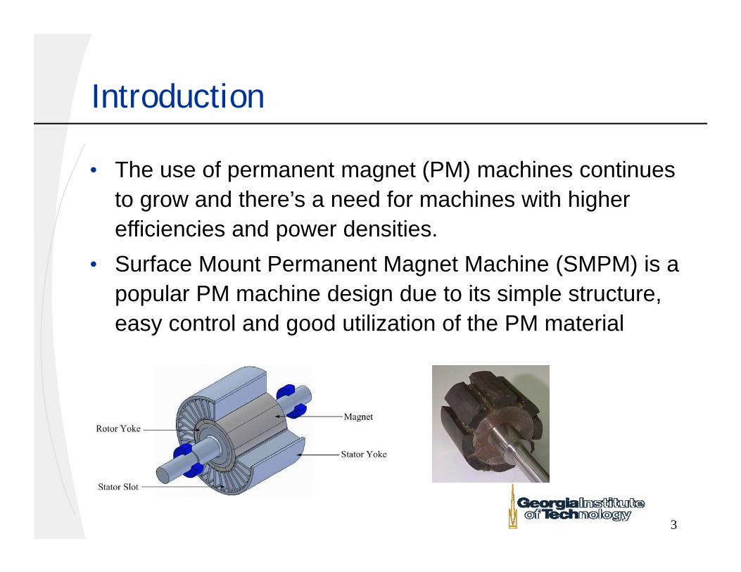
• The use of permanent magnet (PM) machines continues to grow and there’s a need for machines with higher efficiencies and power densities.
• Surface Mount Permanent Magnet Machine (SMPM) is a popular PM machine design due to its simple structure, easy control and good utilization of the PM material
4
Distributed and Concentrated Winding
A-A+
C-
C+
B+B-
B+B-
C+
C-
A-A+
Distributed Winding(DW)
Concentrated Winding(CW)
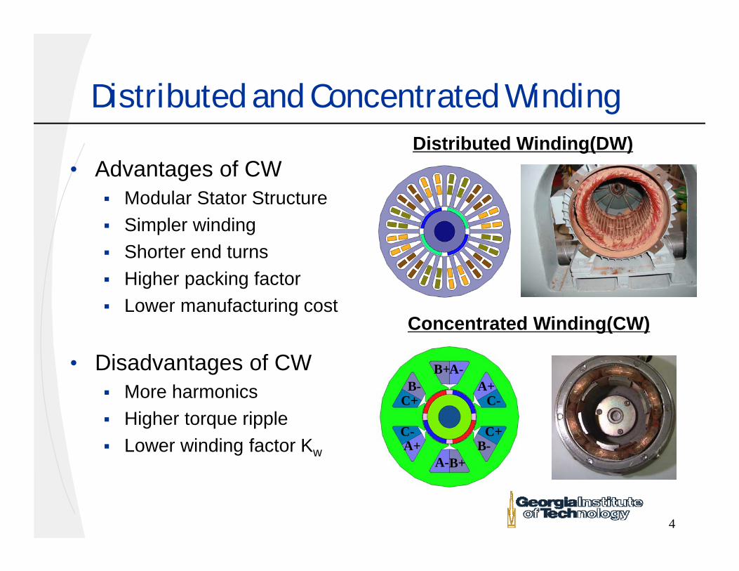
• Advantages of CW Modular Stator Structure Simpler winding Shorter end turns Higher packing factor Lower manufacturing cost
• Disadvantages of CW More harmonics Higher torque ripple Lower winding factor Kw
5
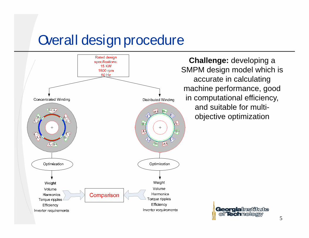
Overall design procedureChallenge: developing a
SMPM design model which is accurate in calculating
machine performance, good in computational efficiency,
and suitable for multi-objective optimization
6
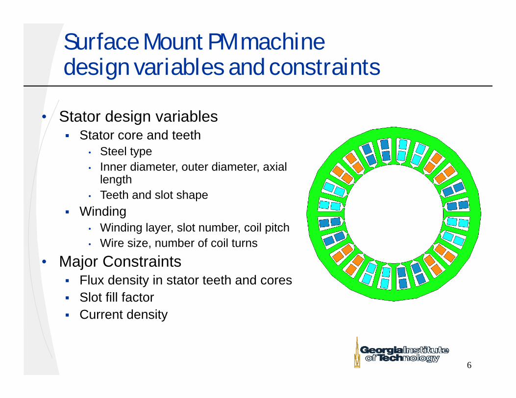
Surface Mount PM machine design variables and constraints
• Stator design variables Stator core and teeth
• Steel type • Inner diameter, outer diameter, axial
length• Teeth and slot shape
Winding• Winding layer, slot number, coil pitch• Wire size, number of coil turns
• Major Constraints Flux density in stator teeth and cores Slot fill factor Current density
7
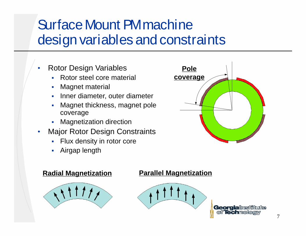
Surface Mount PM machine design variables and constraints
• Rotor Design Variables Rotor steel core material Magnet material Inner diameter, outer diameter Magnet thickness, magnet pole
coverage Magnetization direction
• Major Rotor Design Constraints Flux density in rotor core Airgap length
Pole coverage
Parallel MagnetizationRadial Magnetization
8
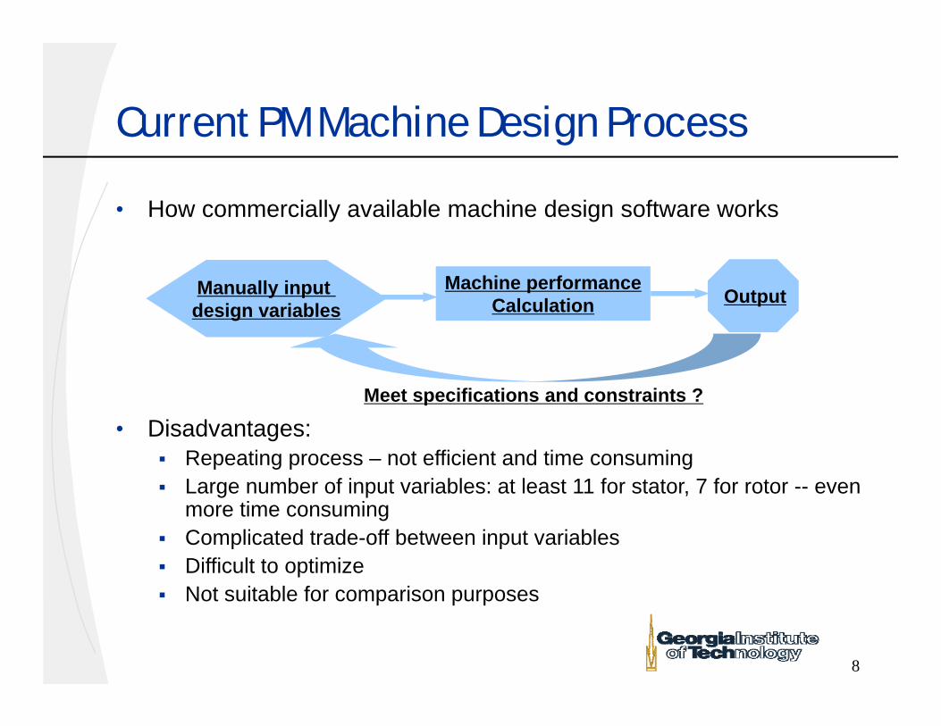
Current PM Machine Design Process
• How commercially available machine design software works
• Disadvantages: Repeating process – not efficient and time consuming Large number of input variables: at least 11 for stator, 7 for rotor -- even
more time consuming Complicated trade-off between input variables Difficult to optimize Not suitable for comparison purposes
Manually input design variables
Machine performanceCalculation
Meet specifications and constraints ?
Output
9
Proposed Improved Design Process—reduce the number of design variables
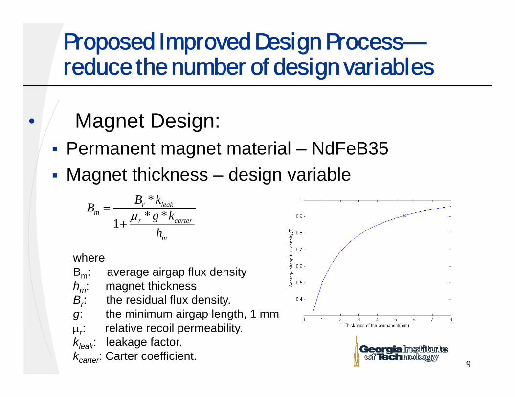
• Magnet Design: Permanent magnet material – NdFeB35 Magnet thickness – design variable
** *1
r leakm
r carter
m
B kB g kh
where Bm: average airgap flux densityhm: magnet thicknessBr: the residual flux density. g: the minimum airgap length, 1 mmr: relative recoil permeability. kleak: leakage factor.kcarter: Carter coefficient.

10
Proposed Improved Design Process—reduce the number of design variables
• Magnet Design: Minimization of cogging
torque, torque ripple, back emf harmonics by selecting pole coverage and magnetization
Pole coverage – 83% Magnetization direction-
Parallel
75o
11
Design of Prototypes
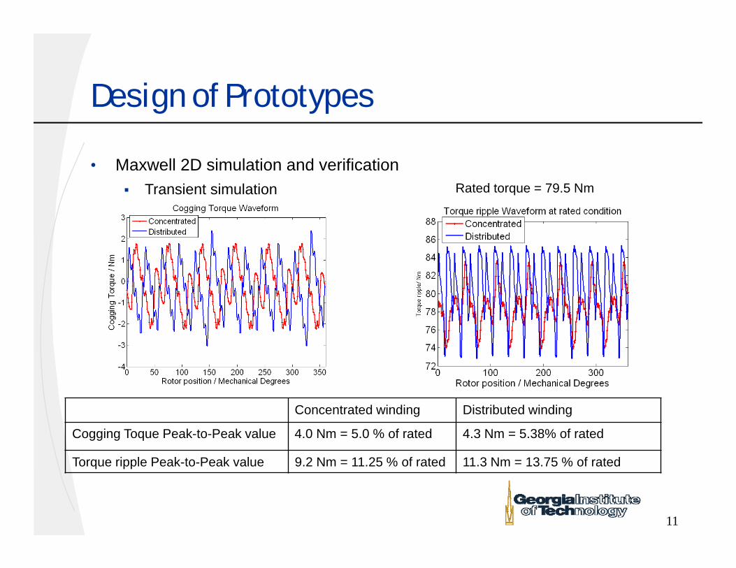
• Maxwell 2D simulation and verification Transient simulation
Concentrated winding Distributed winding
Cogging Toque Peak-to-Peak value 4.0 Nm = 5.0 % of rated 4.3 Nm = 5.38% of rated
Torque ripple Peak-to-Peak value 9.2 Nm = 11.25 % of rated 11.3 Nm = 13.75 % of rated
Rated torque = 79.5 Nm
12
Design specifications and constraints
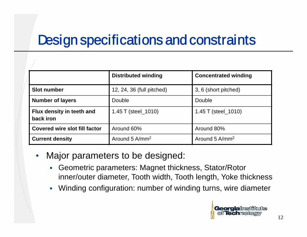
Distributed winding Concentrated winding
Slot number 12, 24, 36 (full pitched) 3, 6 (short pitched)
Number of layers Double Double
Flux density in teeth and back iron
1.45 T (steel_1010) 1.45 T (steel_1010)
Covered wire slot fill factor Around 60% Around 80%
Current density Around 5 A/mm2 Around 5 A/mm2
• Major parameters to be designed: Geometric parameters: Magnet thickness, Stator/Rotor
inner/outer diameter, Tooth width, Tooth length, Yoke thickness Winding configuration: number of winding turns, wire diameter
13
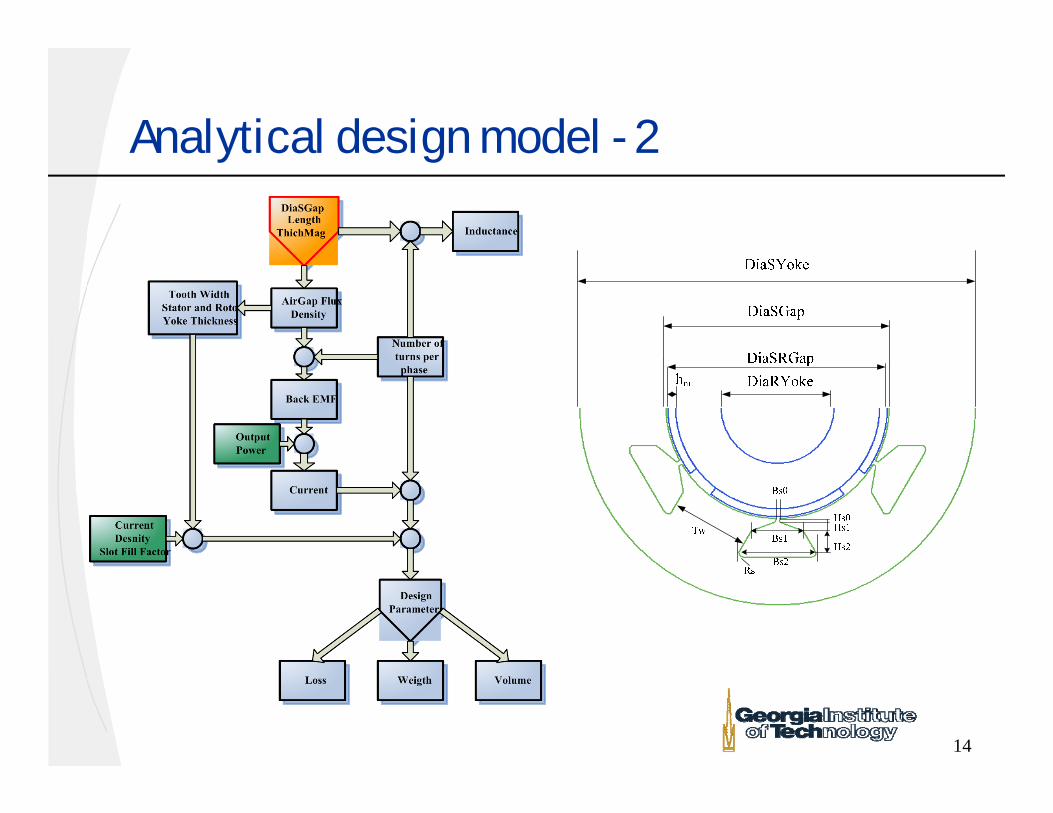
Analytical Design Model - 1
• Build a set of equations to link all other major design inputs and constraints –analytical design model With least number of input variables Minimizes Finite Element Verification needed –
high accuracy model
14
Analytical design model - 2
15
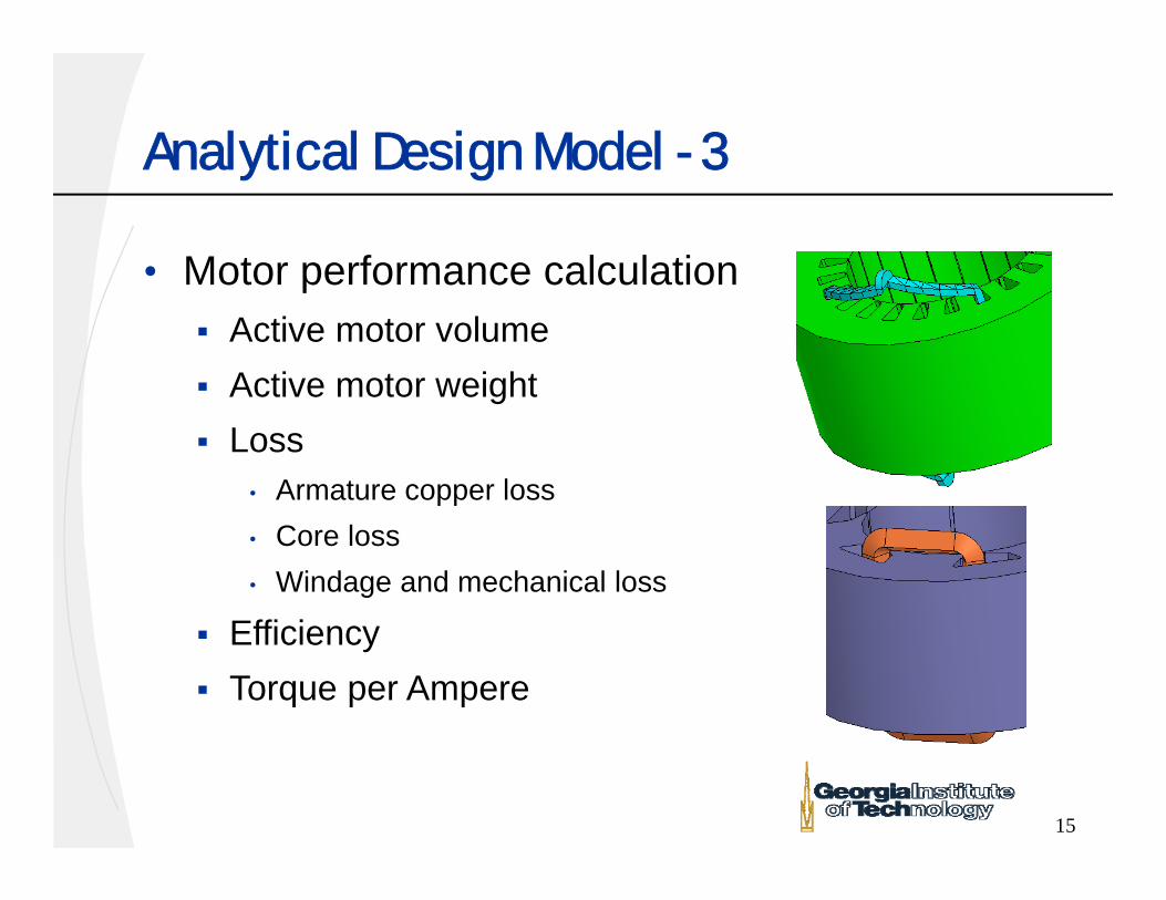
Analytical Design Model - 3
• Motor performance calculation Active motor volume Active motor weight Loss
• Armature copper loss• Core loss• Windage and mechanical loss
Efficiency Torque per Ampere
16
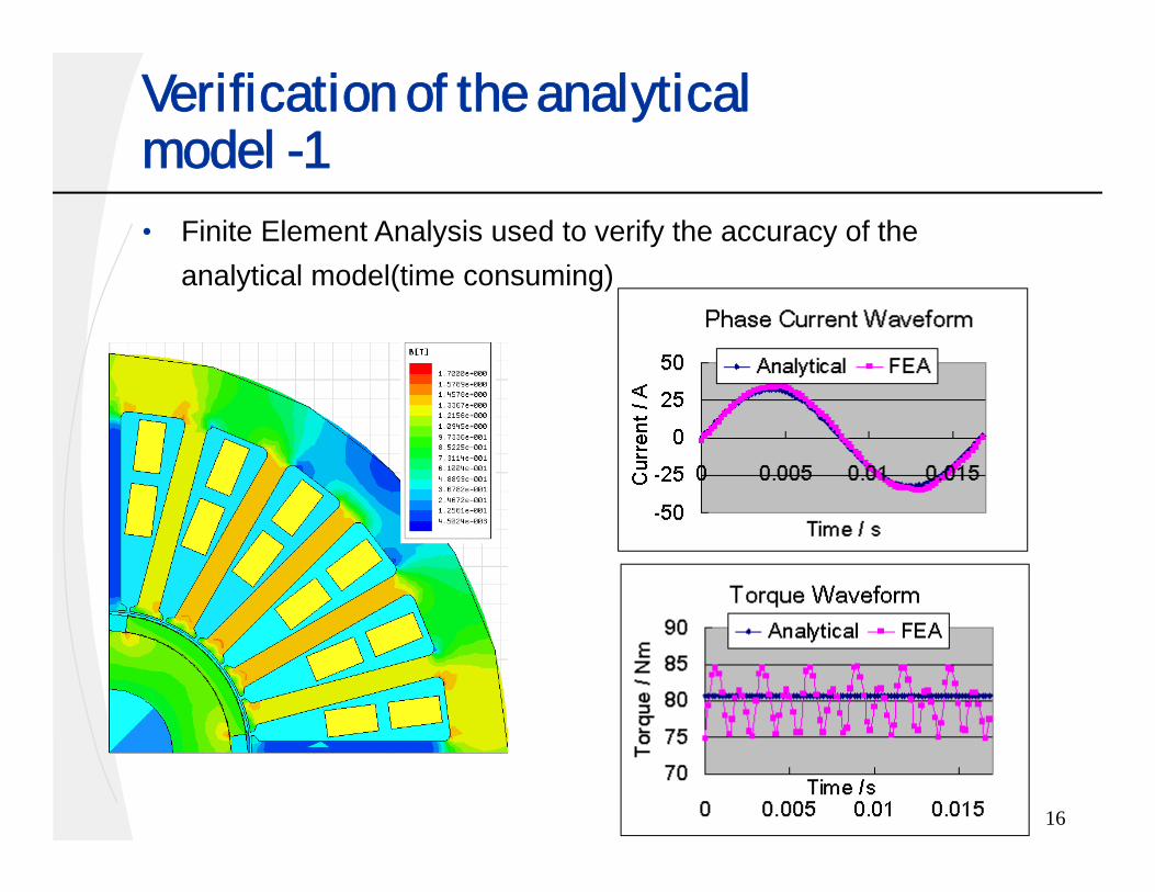
Verification of the analytical model -1• Finite Element Analysis used to verify the accuracy of the
analytical model(time consuming)
17
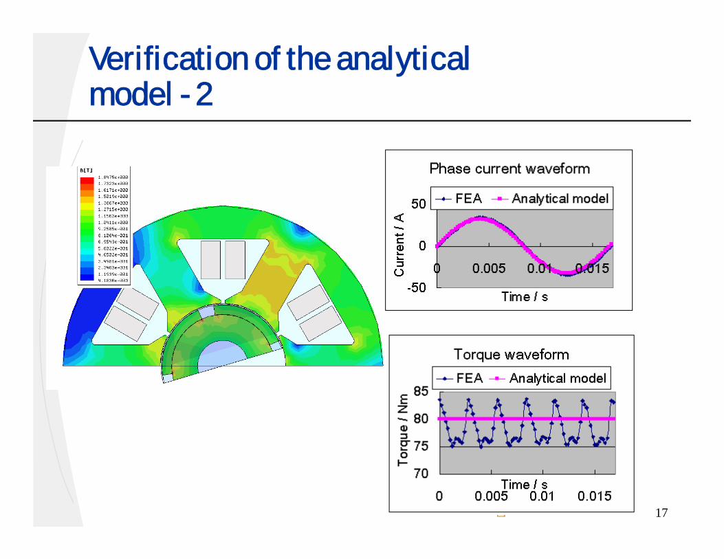
Verification of the analytical model - 2
18
Particle Swarm Optimization - 1
• The traditional gradient-based optimization cannot be applied Equation solving involved in the machine model Wire size and number of turns are discrete valued
• Particle swarm Computation method, gradient free Effective, fast, simple implementation
19
Particle Swarm Optimization - 2
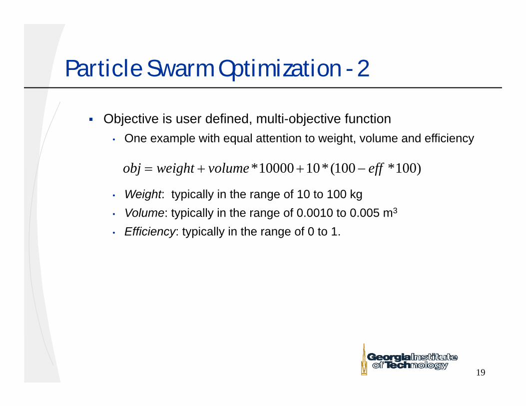
Objective is user defined, multi-objective function• One example with equal attention to weight, volume and efficiency
• Weight: typically in the range of 10 to 100 kg • Volume: typically in the range of 0.0010 to 0.005 m3
• Efficiency: typically in the range of 0 to 1.
*10000 10*(100 *100)obj weight volume eff
20
Particle Swarm Optimization - 3
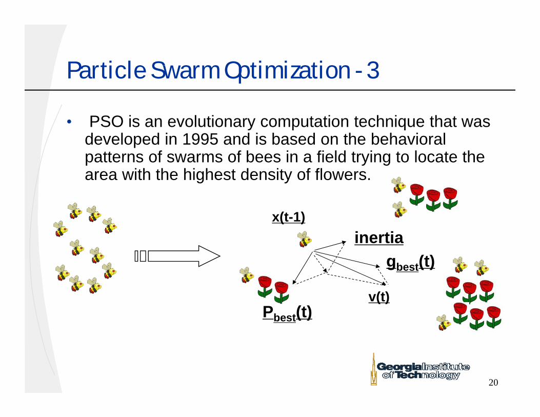
• PSO is an evolutionary computation technique that was developed in 1995 and is based on the behavioral patterns of swarms of bees in a field trying to locate the area with the highest density of flowers.
gbest(t)
Pbest(t)
inertiax(t-1)
v(t)
21
Particle Swarm Optimization - 4
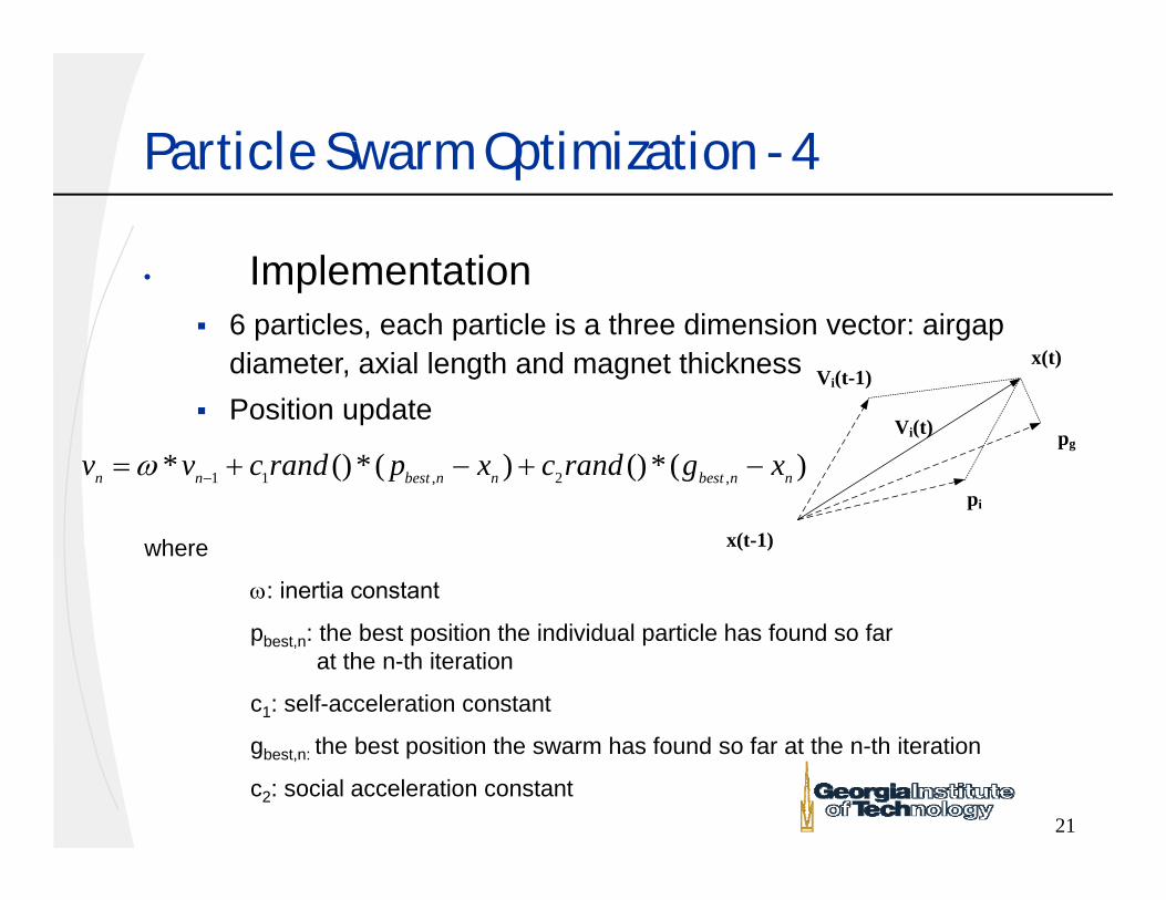
• Implementation 6 particles, each particle is a three dimension vector: airgap
diameter, axial length and magnet thickness Position update
x(t-1)
x(t)Vi(t-1)
Vi(t) pg
pi
1 1 , 2 ,* ()* ( ) () * ( )n n best n n best n nv v c rand p x c rand g x
where
: inertia constant
pbest,n: the best position the individual particle has found so far at the n-th iteration
c1: self-acceleration constant
gbest,n: the best position the swarm has found so far at the n-th iteration
c2: social acceleration constant
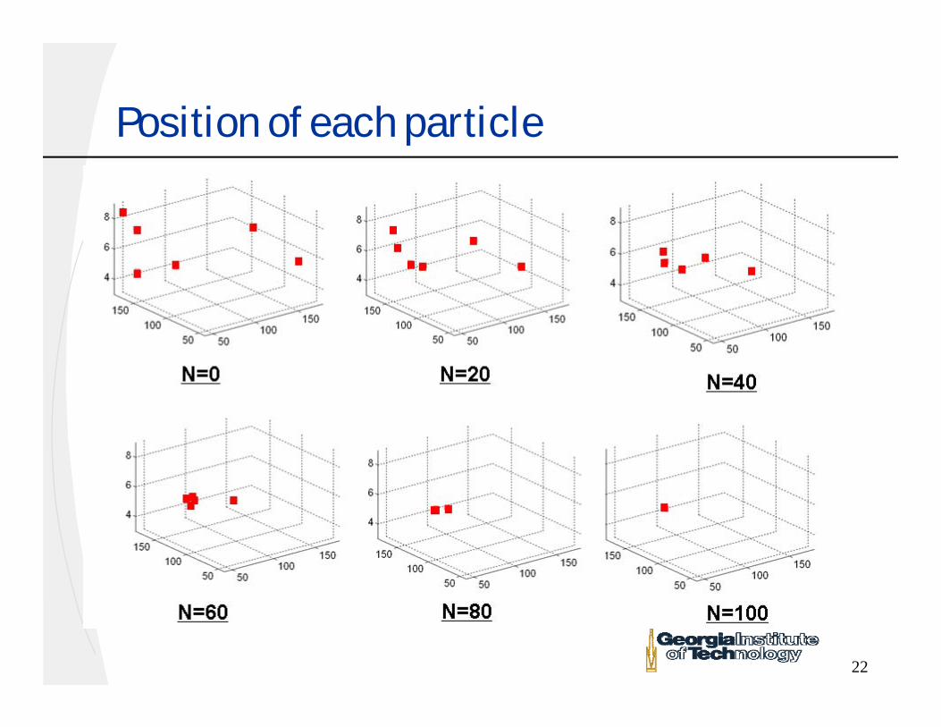
22
Position of each particle
23
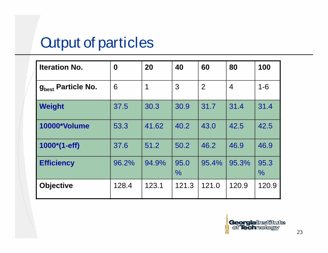
Output of particles
Iteration No. 0 20 40 60 80 100
gbest Particle No. 6 1 3 2 4 1-6
Weight 37.5 30.3 30.9 31.7 31.4 31.4
10000*Volume 53.3 41.62 40.2 43.0 42.5 42.5
1000*(1-eff) 37.6 51.2 50.2 46.2 46.9 46.9
Efficiency 96.2% 94.9% 95.0%
95.4% 95.3% 95.3%
Objective 128.4 123.1 121.3 121.0 120.9 120.9
24
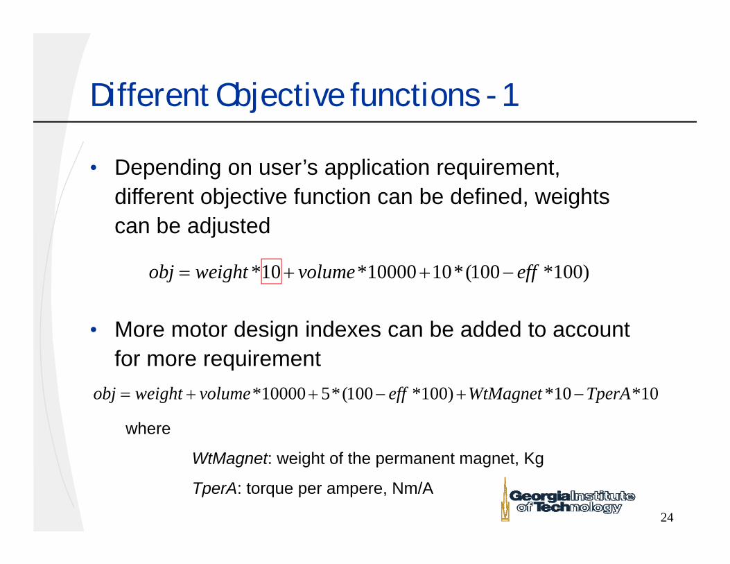
Different Objective functions - 1
• Depending on user’s application requirement, different objective function can be defined, weights can be adjusted
• More motor design indexes can be added to account for more requirement
*10 *10000 10*(100 *100)obj weight volume eff
*10000 5*(100 *100) *10 *10obj weight volume eff WtMagnet TperA
where
WtMagnet: weight of the permanent magnet, Kg
TperA: torque per ampere, Nm/A
25
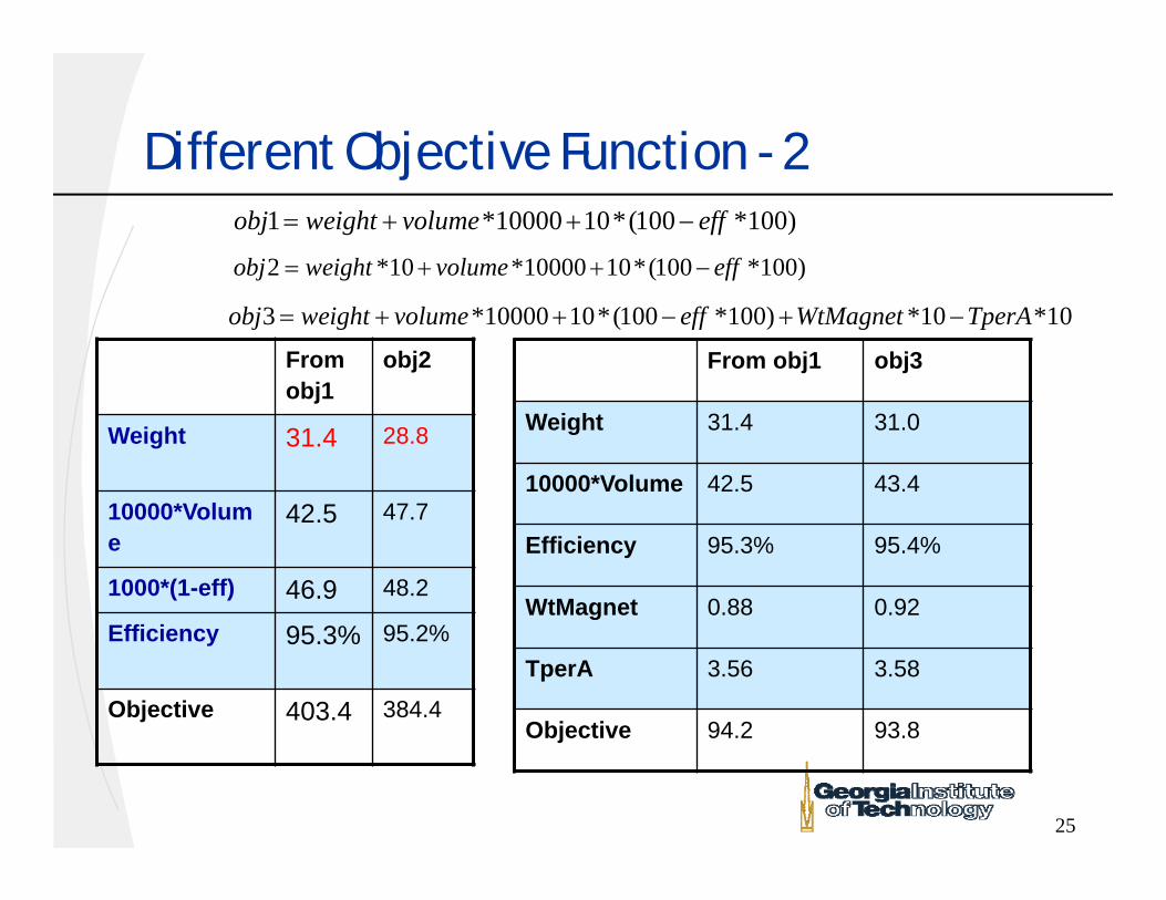
Different Objective Function - 21 *10000 10*(100 *100)obj weight volume eff
2 *10 *10000 10*(100 *100)obj weight volume eff
3 *10000 10*(100 *100) *10 *10obj weight volume eff WtMagnet TperA
From obj1
obj2
Weight 31.4 28.8
10000*Volume
42.5 47.7
1000*(1-eff) 46.9 48.2
Efficiency 95.3% 95.2%
Objective 403.4 384.4
From obj1 obj3
Weight 31.4 31.0
10000*Volume 42.5 43.4
Efficiency 95.3% 95.4%
WtMagnet 0.88 0.92
TperA 3.56 3.58
Objective 94.2 93.8
26
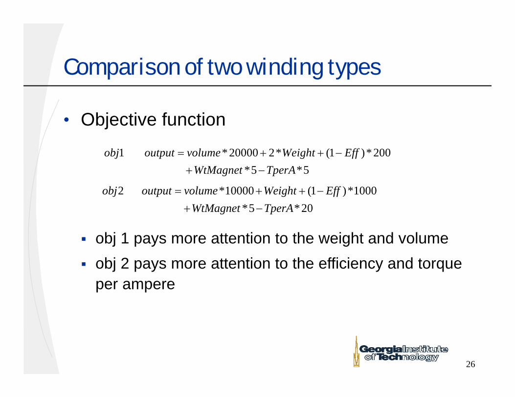
Comparison of two winding types
• Objective function
1 *20000 2* (1 )*200 *5 *5obj output volume Weight Eff
WtMagnet TperA
2 *10000 (1 )*1000 *5 *20obj output volume Weight Eff
WtMagnet TperA
obj 1 pays more attention to the weight and volume obj 2 pays more attention to the efficiency and torque
per ampere
27
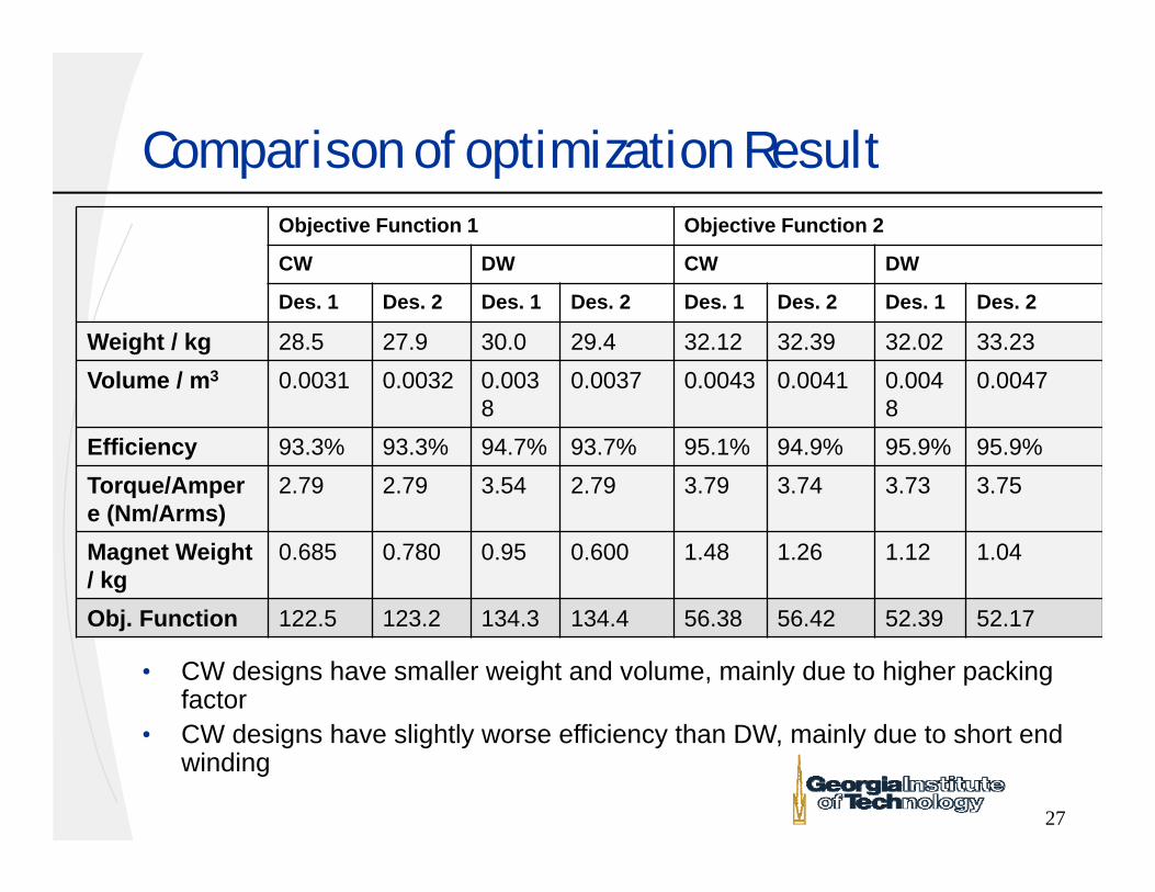
Comparison of optimization Result
• CW designs have smaller weight and volume, mainly due to higher packing factor
• CW designs have slightly worse efficiency than DW, mainly due to short end winding
Objective Function 1 Objective Function 2
CW DW CW DW
Des. 1 Des. 2 Des. 1 Des. 2 Des. 1 Des. 2 Des. 1 Des. 2
Weight / kg 28.5 27.9 30.0 29.4 32.12 32.39 32.02 33.23Volume / m3 0.0031 0.0032 0.003
80.0037 0.0043 0.0041 0.004
80.0047
Efficiency 93.3% 93.3% 94.7% 93.7% 95.1% 94.9% 95.9% 95.9%Torque/Ampere (Nm/Arms)
2.79 2.79 3.54 2.79 3.79 3.74 3.73 3.75
Magnet Weight / kg
0.685 0.780 0.95 0.600 1.48 1.26 1.12 1.04
Obj. Function 122.5 123.2 134.3 134.4 56.38 56.42 52.39 52.17
Conclusion
• Concentrated winding has modular structure, simpler winding and shorter end turns, which lead to lower manufacturing cost
• Before optimization, the torque ripples and harmonics can be minimized by careful design of the magnet pole coverage, magnetization and slot opening
• Analytical design models have been developed for both winding type machines and PSO based multi-objective optimization is applied. This tool, together with user defined objective functions, can be used for analysis and comparison of both winding type machines and different applications
• Optimized result shows CW design have superior performance than convention DW in terms of weight, volume, and have comparable efficiencies.
Acknowledgement
• Financial support for this work from the Grainger Center for Electric Machinery and Electromechanics, at the University of Illinois, Urbana Champaign, is gratefully acknowledged.

Thanks!
Questions and Answers


