126
OPERATING MANUAL ba75863e19 04/2015 Multi 3410 DIGITAL METER FOR DIGITAL IDS SENSORS

OPERATING MANUALba75863e19 04/2015
Multi 3410
DIGITAL METER FOR DIGITAL IDS SENSORS

Multi 3410
Copyright © 2015, WTW GmbHReproduction in whole - or even in part - is prohibited without the express written permission of WTW GmbH, Weilheim.Printed in Germany.
The latest version of the present operating manual is avail-able on the Internet under www.wtw.com.
2 ba75863e19 04/2015

Multi 3410 Contents
Multi 3410 - Contents
1 Overview . . . . . . . . . . . . . . . . . . . . . . . . . . . . . . . . . . . . . 71.1 Keypad . . . . . . . . . . . . . . . . . . . . . . . . . . . . . . . . . . . . . . . 71.2 Display . . . . . . . . . . . . . . . . . . . . . . . . . . . . . . . . . . . . . . . 91.3 Socket field . . . . . . . . . . . . . . . . . . . . . . . . . . . . . . . . . . . 111.4 Automatic sensor recognition . . . . . . . . . . . . . . . . . . . . . 121.5 IDS sensors. . . . . . . . . . . . . . . . . . . . . . . . . . . . . . . . . . . 121.6 IDS adapter for analog sensors . . . . . . . . . . . . . . . . . . . 13
2 Safety . . . . . . . . . . . . . . . . . . . . . . . . . . . . . . . . . . . . . . . 152.1 Authorized use . . . . . . . . . . . . . . . . . . . . . . . . . . . . . . . . 162.2 General safety instructions . . . . . . . . . . . . . . . . . . . . . . . 16
3 Commissioning. . . . . . . . . . . . . . . . . . . . . . . . . . . . . . . 193.1 Scope of delivery. . . . . . . . . . . . . . . . . . . . . . . . . . . . . . . 193.2 Power supply. . . . . . . . . . . . . . . . . . . . . . . . . . . . . . . . . . 193.3 Initial commissioning . . . . . . . . . . . . . . . . . . . . . . . . . . . . 19
3.3.1 Inserting the rechargeable batteries. . . . . . . . . . 203.3.2 Connecting the power pack / charging the
batteries . . . . . . . . . . . . . . . . . . . . . . . . . . . . 203.3.3 Switching on the meter. . . . . . . . . . . . . . . . . . . . 213.3.4 Setting the date and time . . . . . . . . . . . . . . . . . 22
4 Operation. . . . . . . . . . . . . . . . . . . . . . . . . . . . . . . . . . . . 234.1 Switching on the meter . . . . . . . . . . . . . . . . . . . . . . . . . . 234.2 Login with a user name . . . . . . . . . . . . . . . . . . . . . . . . . . 234.3 General operating principles . . . . . . . . . . . . . . . . . . . . . . 26
4.3.1 Operating modes . . . . . . . . . . . . . . . . . . . . . . . . 264.3.2 Navigation . . . . . . . . . . . . . . . . . . . . . . . . . . . . . 264.3.3 Example 1 on navigation: Setting the language. 294.3.4 Example 2 on navigation: Setting the date and
time . . . . . . . . . . . . . . . . . . . . . . . . . . . . . . . . 314.4 Sensor-independent settings . . . . . . . . . . . . . . . . . . . . . 32
4.4.1 System . . . . . . . . . . . . . . . . . . . . . . . . . . . . . . . . 324.4.2 Data storage. . . . . . . . . . . . . . . . . . . . . . . . . . . . 344.4.3 Automatic Stability control . . . . . . . . . . . . . . . . . 344.4.4 Automatic switch-off . . . . . . . . . . . . . . . . . . . . . . 354.4.5 Display illumination . . . . . . . . . . . . . . . . . . . . . . 35
4.5 Sensor info . . . . . . . . . . . . . . . . . . . . . . . . . . . . . . . . . . . 35
3ba75863e19 04/2015

Contents Multi 3410
4.6 pH value. . . . . . . . . . . . . . . . . . . . . . . . . . . . . . . . . . . . . . 374.6.1 General information . . . . . . . . . . . . . . . . . . . . . . 374.6.2 Measuring the pH value . . . . . . . . . . . . . . . . . . . 374.6.3 Settings for pH measurements . . . . . . . . . . . . . . 394.6.4 pH calibration . . . . . . . . . . . . . . . . . . . . . . . . . . . 414.6.5 Calibration interval . . . . . . . . . . . . . . . . . . . . . . . 454.6.6 Carrying out an automatic calibration (AutoCal) . 464.6.7 Carrying out a manual calibration (ConCal) . . . . 504.6.8 Displaying calibration records. . . . . . . . . . . . . . . 544.6.9 Continuous measurement control (CMC
function) . . . . . . . . . . . . . . . . . . . . . . . . . . . . . 554.6.10 QSC function (sensor quality control) . . . . . . 56
4.7 ORP voltage . . . . . . . . . . . . . . . . . . . . . . . . . . . . . . . . . . 594.7.1 General information . . . . . . . . . . . . . . . . . . . . . . 594.7.2 Measuring the ORP . . . . . . . . . . . . . . . . . . . . . . 594.7.3 Settings for ORP measurements . . . . . . . . . . . . 61
4.8 Dissolved oxygen. . . . . . . . . . . . . . . . . . . . . . . . . . . . . . . 624.8.1 General information . . . . . . . . . . . . . . . . . . . . . . 624.8.2 Measuring . . . . . . . . . . . . . . . . . . . . . . . . . . . . . . 634.8.3 Settings for D.O. sensors
(menu or measurement and calibration settings) 654.8.4 FDO® Check procedure (check of the
FDO® 925) . . . . . . . . . . . . . . . . . . . . . . . . . . . 684.8.5 D.O. calibration . . . . . . . . . . . . . . . . . . . . . . . . . . 704.8.6 Displaying calibration records. . . . . . . . . . . . . . . 73
4.9 Conductivity . . . . . . . . . . . . . . . . . . . . . . . . . . . . . . . . . . . 744.9.1 General information . . . . . . . . . . . . . . . . . . . . . . 744.9.2 Measuring . . . . . . . . . . . . . . . . . . . . . . . . . . . . . . 744.9.3 Temperature compensation . . . . . . . . . . . . . . . . 774.9.4 Settings for IDS conductivity sensors . . . . . . . . . 784.9.5 Determining the cell constant
(calibration in control standard) . . . . . . . . . . . . . 814.9.6 Displaying calibration records. . . . . . . . . . . . . . . 83
4.10 Turbidity measurement (VisoTurb® 900-P) . . . . . . . . . . . 844.10.1 General information . . . . . . . . . . . . . . . . . . . . . . 844.10.2 Measuring . . . . . . . . . . . . . . . . . . . . . . . . . . . . . . 854.10.3 Settings for turbidity sensors . . . . . . . . . . . . . . . 864.10.4 Calibration. . . . . . . . . . . . . . . . . . . . . . . . . . . . . . 874.10.5 Calibration data. . . . . . . . . . . . . . . . . . . . . . . . . . 90
4.11 Data storage . . . . . . . . . . . . . . . . . . . . . . . . . . . . . . . . . . 934.11.1 Manual storage . . . . . . . . . . . . . . . . . . . . . . . . . . 944.11.2 Automatic storage at intervals . . . . . . . . . . . . 944.11.3 Editing the measurement data storage. . . . . . . . 974.11.4 Erasing the measurement data storage . . . . . . . 98
4.12 Transmitting data . . . . . . . . . . . . . . . . . . . . . . . . . . . . . . . 994.12.1 USB interfaces . . . . . . . . . . . . . . . . . . . . . . . . . . 994.12.2 Connecting the PC (USB-B interface (USB
Device)) . . . . . . . . . . . . . . . . . . . . . . . . . . . . . 99
4 ba75863e19 04/2015
Contents Multi 3410
4.12.3 Connecting a USB memory device/USB printer (USB-A interface (USB Host)) . . . . . . . . . . . . . 100
4.12.4 Options for data transmission to the USB-B (PC) interface and the USB-A (USB printer) interface . . 100
4.12.5 Data transmission to the USB-A interface (USB memory device) . . . . . . . . . . . . . . . . . . . . . . . . 101
4.12.6 MultiLab Importer . . . . . . . . . . . . . . . . . . . . . . . 1024.13 MultiLab User. . . . . . . . . . . . . . . . . . . . . . . . . . . . . . . . . 1024.14 Reset . . . . . . . . . . . . . . . . . . . . . . . . . . . . . . . . . . . . . . . 102
4.14.1 Resetting the measurement settings . . . . . . . . 1024.14.2 Resetting the system settings. . . . . . . . . . . . . . 105
5 Maintenance, cleaning, disposal . . . . . . . . . . . . . . . . 1075.1 Maintenance . . . . . . . . . . . . . . . . . . . . . . . . . . . . . . . . . 107
5.1.1 Replacing the rechargeable batteries . . . . . . . . 1075.2 Cleaning. . . . . . . . . . . . . . . . . . . . . . . . . . . . . . . . . . . . . 1085.3 Packing . . . . . . . . . . . . . . . . . . . . . . . . . . . . . . . . . . . . . 1085.4 Disposal . . . . . . . . . . . . . . . . . . . . . . . . . . . . . . . . . . . . . 108
6 What to do if... . . . . . . . . . . . . . . . . . . . . . . . . . . . . . . . 1096.1 General information . . . . . . . . . . . . . . . . . . . . . . . . . . . . 1096.2 pH . . . . . . . . . . . . . . . . . . . . . . . . . . . . . . . . . . . . . . . . . 1126.3 Dissolved oxygen. . . . . . . . . . . . . . . . . . . . . . . . . . . . . . 1136.4 Conductivity . . . . . . . . . . . . . . . . . . . . . . . . . . . . . . . . . . 1146.5 Turbidity . . . . . . . . . . . . . . . . . . . . . . . . . . . . . . . . . . . . . 115
7 Technical data . . . . . . . . . . . . . . . . . . . . . . . . . . . . . . . 1177.1 General data . . . . . . . . . . . . . . . . . . . . . . . . . . . . . . . . . 1177.2 Measuring ranges, resolution, accuracy . . . . . . . . . . . . 118
8 Lists . . . . . . . . . . . . . . . . . . . . . . . . . . . . . . . . . . . . . . . 119
9 Appendix: Firmware update. . . . . . . . . . . . . . . . . . . . 1239.1 Firmware update for the meter Multi 3410. . . . . . . . . . . 1239.2 Firmware-Update for IDS Sensors. . . . . . . . . . . . . . . . . 124
5 ba75863e19 04/2015

Multi 3410
6ba75863y19 04/2015

Overview Multi 3410
1 Overview
The compact, digital precision meter Multi 3410 enables you to carry out pH measurements, ORP measurements, conductivity measure-ments, dissolved oxygen (D.O.) measurements and turbidity measure-ments quickly and reliably.
The Multi 3410 provides the maximum degree of operating comfort, reliability and measuring certainty for all applications.
The Multi 3410 supports you in your work with the following functions:
proven calibration procedures
automatic stability control (AR),
automatic sensor recognition,
CMC (continuous measurement control)
QSC (sensor quality control).
The two USB interfaces (USB-A and USB-B) enable you to:
Transmit data to
– a USB memory device
– a PC
Update the meter firmware.
1.1 Keypad
In this operating manual, keys are indicated by brackets <..> .
1 Keypad
2 Display
3 Socket field
1
2
3
7 ba75863e19 04/2015

Multi 3410 Overview
The key symbol (e.g. <MENU/ENTER>) generally indicates a short keystroke (under 2 sec) in this operating manual. A long keystroke (approx. 2 sec) is indicated by the underscore behind the key symbol (e.g. <MENU/ENTER_>).
<F1>:<F2>:
Softkeys providing situation dependent functions, e.g.: <F1>/[Info]: View information on a sensor
<On/Off>:<On/Off_>:
Switches the meter on or off
<M>: Selects the measured parameter
<CAL>: <CAL_>:
Calls up the calibration procedure Displays the calibration data
<AR> Freezes the measured value (HOLD function)Switches the AutoRead measurement on or off
<STO>:<STO_>:
Saves a measured value manuallyOpens the menu for the automatic save function
<RCL>: <RCL_>:
Displays the manually stored measured valuesDisplays the automatically stored measured values
<><>: <><>:
Menu control, navigation
<MENU/ENTER>: <MENU/ENTER_>:
Opens the menu for measurement settings / Confirms entriesOpens the menu for system settings
<PRT><PRT_>
Outputs stored data to the interface Outputs displayed data to the interface in intervals
<ESC>: Cancels an action
F1
F2
CAL
ARAR
MENUENTERMENUENTER
PRT
ESC
8ba75863e19 04/2015

Overview Multi 3410
1.2 Display
1 Status information
2 Measured value (with unit)
3 Measured parameter
4 Continuous measurement control (CMC function)
5 Sensor symbol (calibration evaluation, calibration interval)
6 Measured temperature (with unit)
7 Softkeys and date + time
3
2
1
4
5
6
722.09.2009 08:00Info
9 ba75863e19 04/2015

Multi 3410 Overview
Function displayindicators
AutoCal e.g. TEC
Calibration with automatic buffer recognition, e.g. with the buffer set: Technical buffers
ConCal Calibration with any buffers
Error An error occurred during calibration
AR Stability control (AutoRead) is active
HOLD Measured value is frozen (<AR> key)
Batteries are almost empty
Mains operation
Mains operation with charge functionBatteries are automatically charged in the back-ground.
Data are automatically output to the USB-B inter-face at intervals
Data are output to the USB-A interface (USB flash drive)
Data are output to the USB-A interface (USB printer)If there is a USB-B connection (such as to a PC) at the same time, the data are output only to the USB-B interface.
Power supply via the USB-B interfaceBatteries are not being charged
10ba75863e19 04/2015
Overview Multi 3410
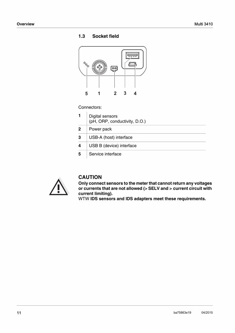
1.3 Socket field
CAUTIONOnly connect sensors to the meter that cannot return any voltages or currents that are not allowed (> SELV and > current circuit with current limiting). WTW IDS sensors and IDS adapters meet these requirements.
Connectors:
1 Digital sensors(pH, ORP, conductivity, D.O.)
2 Power pack
3 USB-A (host) interface
4 USB B (device) interface
5 Service interface
5 1 2 3 4
11 ba75863e19 04/2015

Multi 3410 Overview
1.4 Automatic sensor recognition
The automatic sensor recognition for IDS sensors allows
to operate an IDS sensor at different meters without recalibration
to operate different IDS sensors at one meter without recalibration
to assign measurement data to an IDS sensor
– Measurement datasets are always stored and output with the sensor name and sensor series number.
to assign calibration data to an IDS sensor
– Calibration data and calibration history are always stored and output with the sensor name and sensor series number.
to activate the correct cell constant for conductivity sensors auto-matically
to hide menus automatically that do not concern this sensor
To be able to use the automatic sensor recognition, a meter that sup-ports the automatic sensor recognition (e.g. Multi 3410) and a digital IDS sensor are required.
In digital IDS sensors, sensor data are stored that clearly identify the sensor. The sensor data are automatically taken over by the meter.
1.5 IDS sensors
IDS sensors
support the automatic sensor recognition
show only the settings relevant to the specific sensor in the setting menu
process signals in the sensor digitally so that precise and interfer-ence-free measurements are enabled even with long cables
facilitate to assign a sensor to a measured parameter with differently colored couplings
have quick-lock couplings with which to fix the sensors to the meter.
NoteInformation on available IDS sensors is given on the Internet and in the WTW catalog, "Laboratory and field instrumentation".
12ba75863e19 04/2015

Overview Multi 3410
Sensor data from IDSsensors
IDS sensors transmit the following sensor data to the meter:
SENSOR ID
– Sensor name
– Sensor series number
Calibration data
– Calibration date
– Calibration characteristics
– Calibration interval
– Selected buffer set (IDS pH sensors only)
– Cell constant (IDS conductivity sensors only)
– Calibration history of the last 10 calibrations
Measurement settings (IDS conductivity sensors only)
– The set measured parameter
– The set reference temperature
– The set temperature coefficient
– The set TDS factor
The calibration data are updated in the IDS sensor after each calibra-tion procedure. A message is displayed while the data are being updated in the sensor.
1.6 IDS adapter for analog sensors
With the aid of an IDS adapter, you can also operate analog sensors on the Multi 3410. An IDS adapter and analog sensor together behave like an IDS sensor.The measuring electronics with the stored adapter data are in the adapter head. The adapter data correspond to the sensor data.
NoteIn the measured value display, you can display the sensor name and series number of the selected sensor with the [Info] softkey. You can then display all further sensor data stored in the sensor with the [More] softkey.
NoteInformation on available IDS adapters is given on the Internet and in the WTW catalog, "Laboratory and field instrumentation".Detailed information on the IDS adapter is given in the operating man-ual of the adapter.
13 ba75863e19 04/2015

Multi 3410 Overview
14ba75863e19 04/2015
Safety Multi 3410
2 Safety
This operating manual contains basic instructions that you must follow during the commissioning, operation and maintenance of the meter. Consequently, all responsible personnel must read this operating man-ual before working with the meter. The operating manual must always be available within thevicinity of the meter.
Target group The meter was developed for work in the field and in the laboratory. Thus, we assume that, as a result of their professional training and experience, the operators will know the necessary safety precautions to take when handling chemicals.
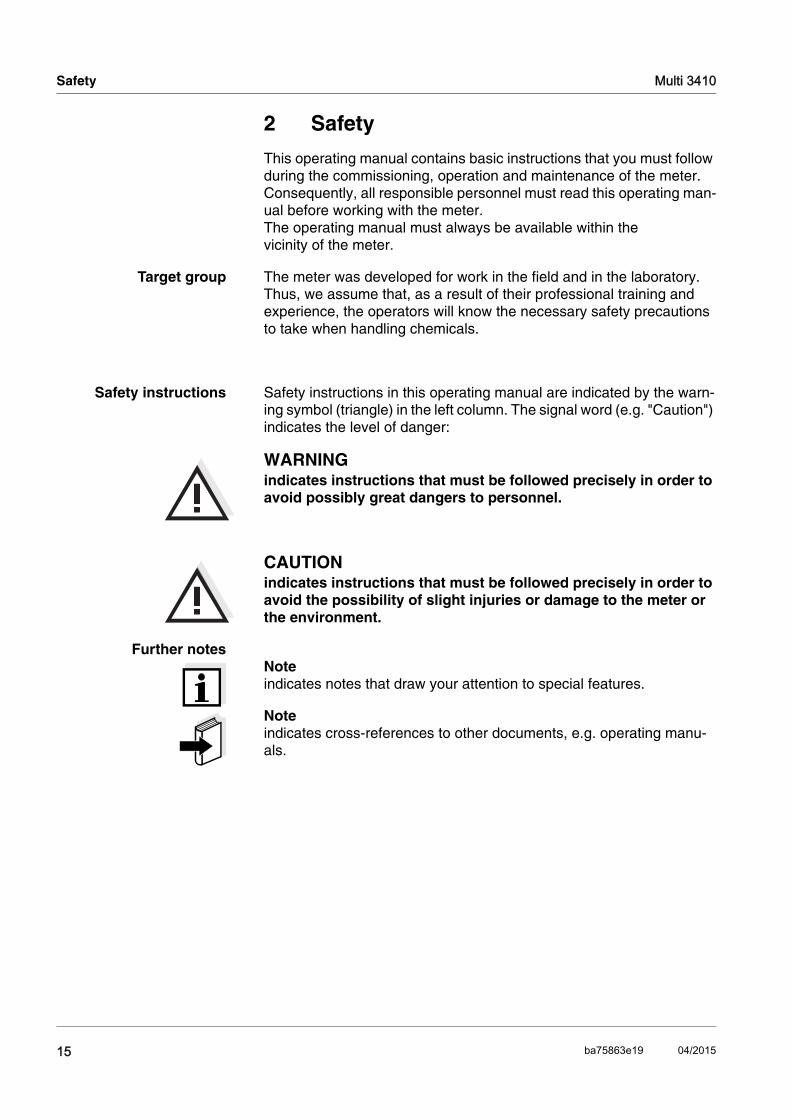
Safety instructions Safety instructions in this operating manual are indicated by the warn-ing symbol (triangle) in the left column. The signal word (e.g. "Caution") indicates the level of danger:
WARNINGindicates instructions that must be followed precisely in order to avoid possibly great dangers to personnel.
CAUTIONindicates instructions that must be followed precisely in order to avoid the possibility of slight injuries or damage to the meter or the environment.
Further notesNoteindicates notes that draw your attention to special features.
Noteindicates cross-references to other documents, e.g. operating manu-als.
15 ba75863e19 04/2015

Multi 3410 Safety
2.1 Authorized use
The authorized use of the meter consists exclusively of the measure-ment of the pH, ORP, conductivity and dissolved oxygen in a field and laboratory environment. The technical specifications as given in chapter 7 TECHNICAL DATA must be observed. Only the operation and running of the meter according to the instructions given in this operating manual is authorized. Any other use is considered unauthorized.
2.2 General safety instructions
This meter is constructed and tested in compliance with the IEC 1010 safety regulations for electronic measuring instruments. It left the factory in a safe and secure technical condition.
Function andoperational safety
The smooth functioning and operational safety of the meter can only be guaranteed if the generally applicable safety measures and the specific safety instructions in this operating manual are followed during opera-tion.
The smooth functioning and operational safety of the meter can only be guaranteed under the environmental conditions that are specified in chapter 7 TECHNICAL DATA.
If the meter was transported from a cold environment to a warm envi-ronment, the formation of condensate can lead to the faulty functioning of the meter. In this event, wait until the temperature of the meter reaches room temperature before putting the meter back into opera-tion.
CAUTIONThe meter is only allowed to be opened by authorized personnel.
16ba75863e19 04/2015
Safety Multi 3410
Safe operation If safe operation is no longer possible, the meter must be taken out of service and secured against inadvertent operation!Safe operation is no longer possible if the meter:
has been damaged in transport
has been stored under adverse conditions for a lengthy period of time
is visibly damaged
no longer operates as described in this manual.
If you are in any doubt, please contact the supplier of the meter.
Obligations of thepurchaser
The purchaser of this meter must ensure that the following laws and guidelines are observed when using dangerous substances:
EEC directives for protective labor legislation
National protective labor legislation
Safety regulations
Safety datasheets of the chemical manufacturers.
CAUTIONIn addition to the safety instructions mentioned here, also follow the safety instructions of the sensors used.The operating manuals of the sensors are available on the sup-plied CD and on the Internet under www.wtw.com.
17 ba75863e19 04/2015

Multi 3410 Safety
18ba75863e19 04/2015

Commissioning Multi 3410
1
3 Commissioning
3.1 Scope of delivery
Meter Multi 3410
4 NiMH rechargeable batteries 1.2 V Mignon type AA
USB cable (A plug on mini B plug)
Power pack
Short instructions
Detailed operating manual (4 languages)
CD-ROM
3.2 Power supply
The Multi 3410 is supplied with power in the following ways:
Battery operation with NiMh rechargeable batteries
Mains operation with the supplied power pack.The NiMh rechargeable batteries are automatically charged while the power pack is connected.
USB operation via a connected USB-B cable.The inserted NiMh rechargeable batteries are not charged
3.3 Initial commissioning
Perform the following activities:
Insert the rechargeable batteries and charge them
Connect the power pack (mains operation / battery charging)
Switch on the meter
Set the date and time
9 ba75863e19 04/2015

Multi 3410 Commissioning
3.3.1 Inserting the rechargeable batteries
CAUTIONMake sure that the poles of the rechargeable batteries are posi-tioned correctly.The ± signs on the batteries must correspond to the ± signs in the battery compartment.
3.3.2 Connecting the power pack / charging the batteries
CAUTIONThe line voltage at the operating site must lie within the input volt-age range of the original power pack (see section 7.1).
CAUTIONUse original power packs only (see section 7.1).
CAUTIONThe batteries in the battery compartment are automatically charged when the power pack is connected.
1 Unscrew the two screws (1) on the underside of the meter.
2 Open the battery compartment (2) on the underside of the meter.
3 Place four rechargeable batteries (type Mignon AA) in the bat-tery compartment.
4 Close the battery compartment (2) and tighten the screws (1).
2
1
20ba75863e19 04/2015
Commissioning Multi 3410
Make sure that only NiMH rechargeable batteries are in the battery compartment. The charging process is optimized for NiMH re-chargeable batteries. Other battery types can cause damage dur-ing the charging process.Make sure that the ambient temperature is max. 40 °C while the power pack is connected.
During mains operation, one of the following symbols is displayed:
NoteCharge the batteries completely prior to putting the meter into operation for the first time. The charging process takes approx. 10 hours. The
symbol is displayed if the batteries are nearly discharged.
3.3.3 Switching on the meter
NoteThe meter has an energy saving feature to avoid unnecessary power consumption during battery operation. The energy saving feature switches off the meter during battery opera-tion if no key is pressed during the adjusted interval. (How to set the switch-off interval, see section 4.4).The switch-off interval of the energy saving feature is not active when the meter is supplied with power via the power pack or the USB-B
1 Connect the plug of the power pack to the socket for the power pack on the Multi 3410.
2 Connect the original power pack to an easily accessible power outlet.
: Mains operation with charge functionBatteries are automatically charged in the background.
: Mains operation
1 Press the <On/Off> key.The meter performs a self-test. The display shows the manufacturer's logo while the self-test is being performed.
2 Connect the sensor.The meter switches to the measuring mode (measured value display).
21 ba75863e19 04/2015

Multi 3410 Commissioning
cable.
3.3.4 Setting the date and time
3 See section 4.3.4
22ba75863e19 04/2015

Operation Multi 3410
4 Operation
4.1 Switching on the meter
Switching on Press the <On/Off> (or <On/Off_>) key.The meter performs a self-test. The display shows the manufacturer's logo while the self-test is being performed.If a sensor is connected, the measured value display appears.
NoteIf the user administration function is activated, the Login dialog appears after the meter is switched on (see section 4.2).
The user administration function is not active in the delivery condition.The user administration function is activated by the administrator via the MultiLab User PC software (see the MultiLab User operating manual).
Switching off Press the <On/Off> (or <On/Off_>) key.
4.2 Login with a user name
After activation of the user administration by the administrator, mea-surements are only possible after login with a user name. The user name is documented with the measured values and in records.
All user names entered by the administrator are listed in the User name menu. The administrator determines for each user whether or not a password is required for login to the meter.
If the Password menu item is grayed out, no password is required for login.
15.09.2014 08:00Info
1 Switch on the meter with <On/Off> (or <On/Off_>).The Login dialog box appears.
23 ba75863e19 04/2015

Multi 3410 Operation
NoteThe login is done immediately if no password is required.If a sensor is connected the measured value display appears.
NoteThe user specifies the password when he or she first logs in with a user name. A valid password consists of 4 digits. The user can change the password with the next login.
2 Using <><>, enter the User name menu item and confirm with <MENU/ENTER>.The user name is highlighted.
3 Using <><>, select a user name and confirm with <MENU/ENTER>.
4 If a password is required:Using <><>, enter the Password menu item and confirm with <MENU/ENTER>.
5 Change the digit of the highlighted position with <><>.Go to the next digit of the password with <><>.When the password was completely entered, confirm with <MENU/ENTER>. The login takes place. If a sensor is connected the measured value display appears.
User name AdminPassword ####Change password
Login
15.03.2014 08:00
24ba75863e19 04/2015

Operation Multi 3410
Changing the password If the administrator has set up the access with password protection:
Forgotten thepassword?
Contact the administrator.
1 Switch on the meter with <On/Off> (or <On/Off_>).The Login dialog box appears.
2 Using <><>, enter the User name menu item and confirm with <MENU/ENTER>.The user name is highlighted.
3 Using <><>, select a user name and confirm with <MENU/ENTER>.
4 Using <><>, enter the Change password menu item and confirm with <MENU/ENTER>.
5 Enter the old password in the Password box with <><> and <><> and confirm with <MENU/ENTER>.
6 Enter the new password in the New password box with <><> and <><> and confirm with <MENU/ENTER>.The password is changed. The login takes place. If a sensor is connected the measured value display appears.
25 ba75863e19 04/2015

Multi 3410 Operation
4.3 General operating principles
This section contains basic information on the operation of the Multi 3410.
Operating elements,display
An overview of the operating elements and the display is given in sec-tion 1.1 and section 1.2.
Operating modes,navigation
An overview of the operating modes and navigation of the Multi 3410 is given in section 4.3.1 and section 4.3.2.
4.3.1 Operating modes
The meter has the following operating modes:
MeasuringThe measurement data of the connected sensor is shown in the measured value display
CalibrationThe course of a calibration with calibration information, functions and settings is displayed
Storage in memoryThe meter stores measuring data automatically or manually
Data transmissionThe meter transmits measuring data and calibration records to a USB-B interface automatically or manually.
SettingThe system menu or a sensor menu with submenus, settings and functions is displayed
4.3.2 Navigation
Measured value display In the measured value display, you can
open the menu for calibration and measurement settings with <MENU/ENTER> (short keystroke)
open the system menu with the sensor-independent settings by pressing <MENU/ENTER>Storage & config for a <MENU/ENTER_>long keystroke, approx. 2 s).
change the display in the selected measuring window (e. g. pH ><− mV) by pressing <M>.
26ba75863e19 04/2015

Operation Multi 3410
Menus and dialogs The menus for settings and dialogs in procedures contain further sub-menus. The selection is made with the <><> keys. The current selection is displayed with a frame.
SubmenusThe name of the submenu is displayed at the upper edge of the frame. Submenus are opened by confirming with <MENU/ENTER>. Example:
SettingsSettings are indicated by a colon. The current setting is displayed on the right-hand side. The setting mode is opened with <MENU/ENTER>. Subsequently, the setting can be changed with <><> and <MENU/ENTER>. Example:
FunctionsFunctions are designated by the name of the function. They are immediately carried out by confirming with <MENU/ENTER>. Example: Display the Calibration record function.
GeneralInterfaceClock functionService informationReset
System
15.03.2014 08:00
Language: DeutschAcoustic signal: offVolume 9Illumination: onBrightness: 12Switchoff time: 1 hTemperature unit: °CStability control: on
General
15.03.2014 08:00
27 ba75863e19 04/2015

Multi 3410 Operation
MessagesInformation is marked by the [i] symbol. They cannot be selected. Example:
NoteThe principles of navigation are explained in the two following sections by reference of examples:
Setting the language (section 4.3.3)
Setting the date and time (see section 4.3.4).
Calibration recordCalibration data storageBuffer: TECSingle-point calibration: yesCalibration interval: 7 dUnit for slope: mV/pH
[i] 2.00 4.01 7.00 10.01 (25 °C)
pH
15.03.2014 08:00
Calibration recordCalibration data storageBuffer: TECSingle-point calibration: yesCalibration interval: 7 dUnit for slope: mV/pH
[i] 2.00 4.01 7.00 10.01 (25 °C)
pH
15.03.2014 08:00
28ba75863e19 04/2015
Operation Multi 3410
4.3.3 Example 1 on navigation: Setting the language
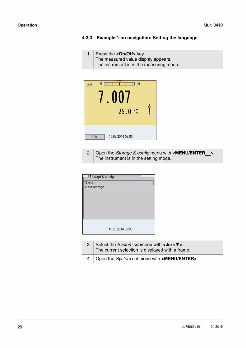
1 Press the <On/Off> key.The measured value display appears.The instrument is in the measuring mode.
2 Open the Storage & config menu with <MENU/ENTER_>.The instrument is in the setting mode.
3 Select the System submenu with <><>. The current selection is displayed with a frame.
4 Open the System submenu with <MENU/ENTER>.
15.03.2014 08:00Info
System Data storage
Storage & config
15.03.2014 08:00
29 ba75863e19 04/2015

Multi 3410 Operation
5 Select the General submenu with <><>. The current selection is displayed with a frame.
6 Open the General submenu with <MENU/ENTER>.
7 Open the setting mode for the Language with <MENU/ENTER>.
8 Select the required language with <><>.
GeneralInterface Clock function Service information Reset
System
15.03.2014 08:00
Language: DeutschAcoustic signal: offVolume 5Illumination: onBrightness: 50 %Switchoff time: 1 hTemperature unit: °CStability control: on
General
15.03.2014 08:00
Language: DeutschAcoustic signal: offVolume 5Illumination: onBrightness: 50 %Switchoff time: 1 hTemperature unit: °CStability control: on
General
15.03.2014 08:00
30ba75863e19 04/2015

Operation Multi 3410
4.3.4 Example 2 on navigation: Setting the date and time
The measuring instrument has a clock with a date function. The date and time are indicated in the status line of the measured value display. When storing measured values and calibrating, the current date and time are automatically stored as well.
The correct setting of the date and time and date format is important for the following functions and displays:
Current date and time
Calibration date
Identification of stored measured values.
Therefore, check the time at regular intervals.
NoteAfter a fall of the supply voltage (empty batteries), the date and time are reset.
Setting the date, timeand date format
The date format can be switched from the display of day, month, year (dd.mm.yy) to the display of month, day, year (mm/dd/yy or mm.dd.yy).
9 Confirm the setting with <MENU/ENTER>. The meter switches to the measuring mode.The selected language is active.
1 In the measured value display:Open the Storage & config menu with <MENU/ENTER_>.The instrument is in the setting mode.
2 Select and confirm the System / Clock function menu with <><> and <MENU/ENTER>.The setting menu for the date and time opens up.
Date format: dd.mm.yyDate: 15.03.2014Time: 14:53:40
Clock function
15.03.2014 08:00
31 ba75863e19 04/2015
Multi 3410 Operation
4.4 Sensor-independent settings
The Storage & config menu includes the following settings:
System (see section 4.4.1).
Data storage (see section 4.4.2)
4.4.1 System
Overview The following sensor-independent meter characteristics can be adjusted in the Storage & config/System menu:
Menu language
Beep on keystroke
Loudness of the beep
Illumination
Brightness
Interval of the automatic switchoff
Data interface
Clock and date function
Reset of all sensor-independent system settings to the default con-dition
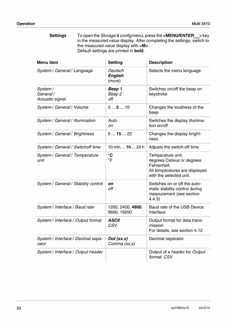
3 Select and confirm the Time menu with <><> and <MENU/ENTER>.The hours are highlighted.
4 Change and confirm the setting with <><> and <MENU/ENTER>.The minutes are highlighted.
5 Change and confirm the setting with <><> and <MENU/ENTER>.The seconds are highlighted.
6 Change and confirm the setting with <><> and <MENU/ENTER>.The time is set.
7 If necessary, set the Date and Date format. The setting is made similarly to that of the time.
8 To make further settings, switch to the next higher menu level with <ESC>.orSwitch to the measured value display with <M>. The instrument is in the measuring mode.
32ba75863e19 04/2015
Operation Multi 3410
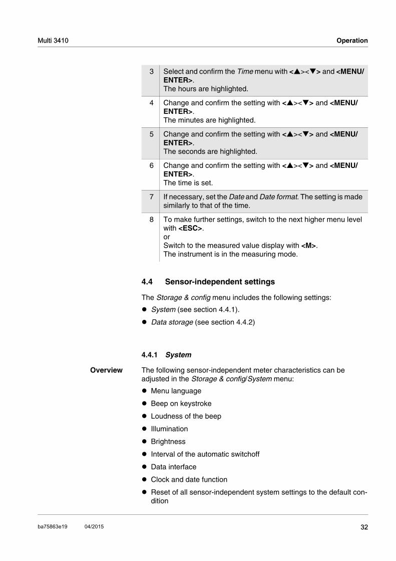
Settings To open the Storage & config menu, press the <MENU/ENTER_> key in the measured value display. After completing the settings, switch to the measured value display with <M>. Default settings are printed in bold.
Menu item Setting Description
System / General / Language DeutschEnglish(more)
Selects the menu language
System / General / Acoustic signal
Beep 1Beep 2off
Switches on/off the beep on keystroke
System / General / Volume 0 ... 5 ... 10 Changes the loudness of the beep
System / General / Illumination Autoon
Switches the display illumina-tion on/off
System / General / Brightness 0 ... 15 ... 22 Changes the display bright-ness
System / General / Switchoff time 10 min ... 1h ... 24 h Adjusts the switch-off time
System / General / Temperature unit
°C °F
Temperature unit, degrees Celsius or degrees Fahrenheit.All temperatures are displayed with the selected unit.
System / General / Stability control onoff
Switches on or off the auto-matic stability control during measurement (see section 4.4.3)
System / Interface / Baud rate 1200, 2400, 4800, 9600, 19200
Baud rate of the USB Device interface
System / Interface / Output format ASCIICSV
Output format for data trans-missionFor details, see section 4.12
System / Interface / Decimal sepa-rator
Dot (xx.x)Comma (xx,x)
Decimal separator
System / Interface / Output header Output of a header for Output format: CSV
33 ba75863e19 04/2015

Multi 3410 Operation
4.4.2 Data storage
This menu contains all functions to display, edit and erase stored mea-sured values.
NoteDetailed information on the storage functions of the Multi 3410 is given in section 4.11.
4.4.3 Automatic Stability control
The automatic Stability control (AutoRead) function continuously checks the stability of the measurement signal. The stability has a con-siderable impact on the reproducibility of measured values.
You can activate or switch off the automatic Stability control function (see section 4.4).
The measured parameter flashes on the display
as soon as the measured value is outside the stability range
when you switch over between the measured parameters with <M>.
System / Interface / Extended Oxi output
The measured values for the parameters concentration (mg/l) and saturation (%) are output together.The function is active if the fol-lowing requirements are met: A D.O. sensor is connected
The D.O. sensor displays the parameter concentration (mg/l) or saturation (%)
The Output format CSV is selected
System /Clock function Date formatDateTime
Settings of time and date. For details, see section 4.3.4
System /Service information Hardware version and software version of the meter are dis-played.
System /Reset - Resets the system settings to the default values. For details, see section 4.14.2
Menu item Setting Description
34ba75863e19 04/2015

Operation Multi 3410
when the automatic Stability control is switched off.
4.4.4 Automatic switch-off
The instrument has an automatic switchoff function in order to save the batteries (see section 4.4.1). The automatic switchoff switches off the measuring instrument if no key is pressed for an adjustable period.
The automatic switchoff is not active
if the power pack is connected
if a USB-B cable is connected
if the Automatic data storage function is active, or with automatic data transmission
4.4.5 Display illumination
The meter automatically switches the display illumination to energy saving mode if no key is pressed for 20 seconds. The illumination is switched on with the next keystroke again.
You can also generally switch on the display illumination (see section 4.4.1).
4.5 Sensor info
You can display the current sensor data and sensor settings of a con-nected sensor at any time. The sensor data are available in the mea-sured value display with the [Info] softkey.
1 In the measured value display:Display the sensor data (sensor name, series number) with [Info].
15.03.2014 08:00Info
35 ba75863e19 04/2015
Multi 3410 Operation
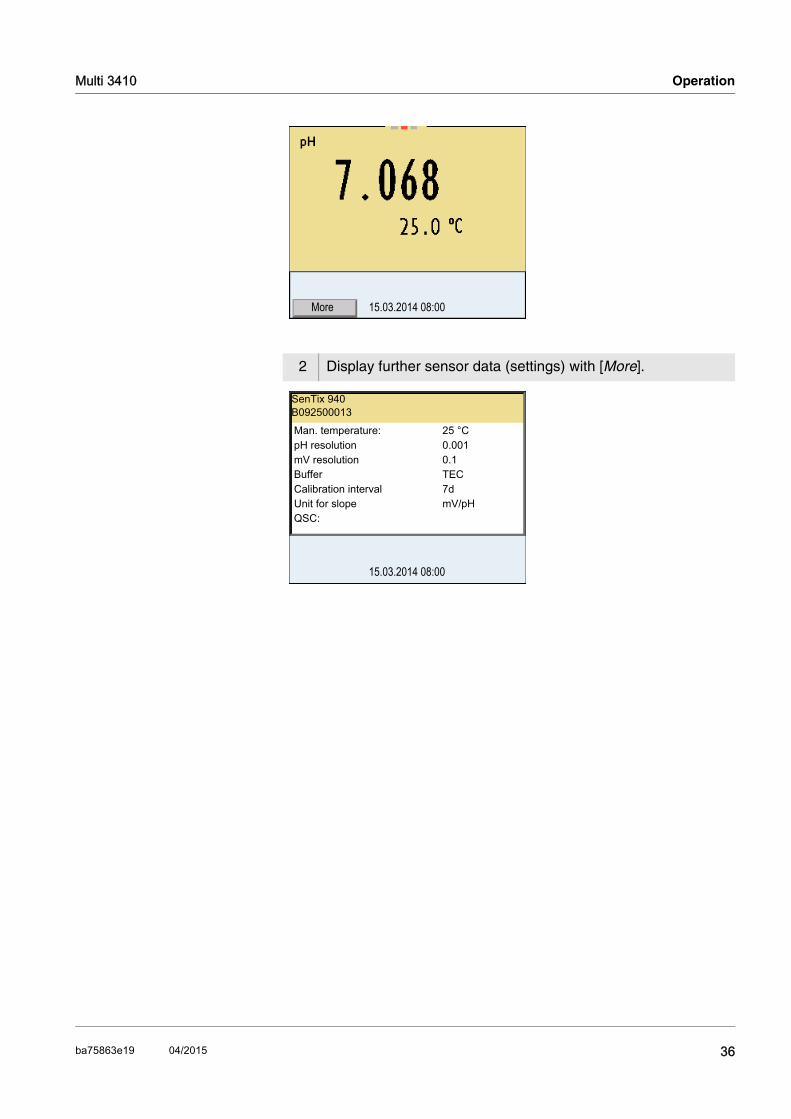
2 Display further sensor data (settings) with [More].
15.03.2014 08:00More
15.03.2014 08:00
Man. temperature: 25 °CpH resolution 0.001mV resolution 0.1Buffer TECCalibration interval 7dUnit for slope mV/pHQSC:
SenTix 940B092500013
36ba75863e19 04/2015
Operation Multi 3410
4.6 pH value
4.6.1 General information
You can measure the following parameters:
pH value [ ]
Sensor voltage [mV]
NoteThe sensor connection and the USB-B (device) interface are galvani-cally isolated. This enables interference-free measurements in grounded measuring media.
Temperaturemeasurement
For reproducible pH measurements, it is essential to measure the tem-perature of the test sample. IDS sensors measure the temperature with a temperature sensor integrated in the IDS sensor.
Preparatory activities Perform the following preparatory activities when you want to measure:
4.6.2 Measuring the pH value
When operating a sensor without integrated temperature sensor, e.g. via an IDS pH adapter, you have to determine and input the tempera-ture of the measuring medium first.
1 Connect the IDS pH sensor to the meter.The pH measuring window is displayed.
2 If necessary, select the measured parameter with <M>.
3 If necessary, calibrate or check the IDS pH sensor.
1 Perform the preparatory activities according to section 4.6.1.
2 Immerse the IDS pH sensor in the test sample.
37 ba75863e19 04/2015

Multi 3410 Operation
Stability control(AutoRead )
The stability control function (AutoRead) continually checks the stability of the measurement signal. The stability has a considerable impact on the reproducibility of measured values. The display of the measured parameter flashes until a stable measured value is available.
You can start the Stability control manually at any time, irrespective of the setting for automatic Stability control (see section 4.4.3) in the Sys-tem menu.
NoteYou can prematurely terminate the Stability control function manually with <MENU/ENTER> at any time. If the Stability control function is pre-maturely terminated, the current measurement data are output to the interface without the AutoRead info.
3 Select the pH or mV display with <M>.
15.03.2014 08:00Info
1 Freeze the measured value with <AR>.The [HOLD] status indicator is displayed.
2 Using <MENU/ENTER>, activate the Stability control function manually.The [AR] status indicator appears while the measured value is assessed as not stable. A progress bar is displayed and the display of the measured parameter flashes.The [HOLD][AR] status indicator appears as soon as a stable measured value is recognized. The progress bar disappears and the display of the measured parameter stops flashing. The current measurement data is output to the interface. Mea-surement data meeting the stability control criterion is marked by AR.
3 Release the frozen measured value again with <AR> or <M>.The [AR] status display disappears. The display switches back to the previous indication.
38ba75863e19 04/2015
Operation Multi 3410
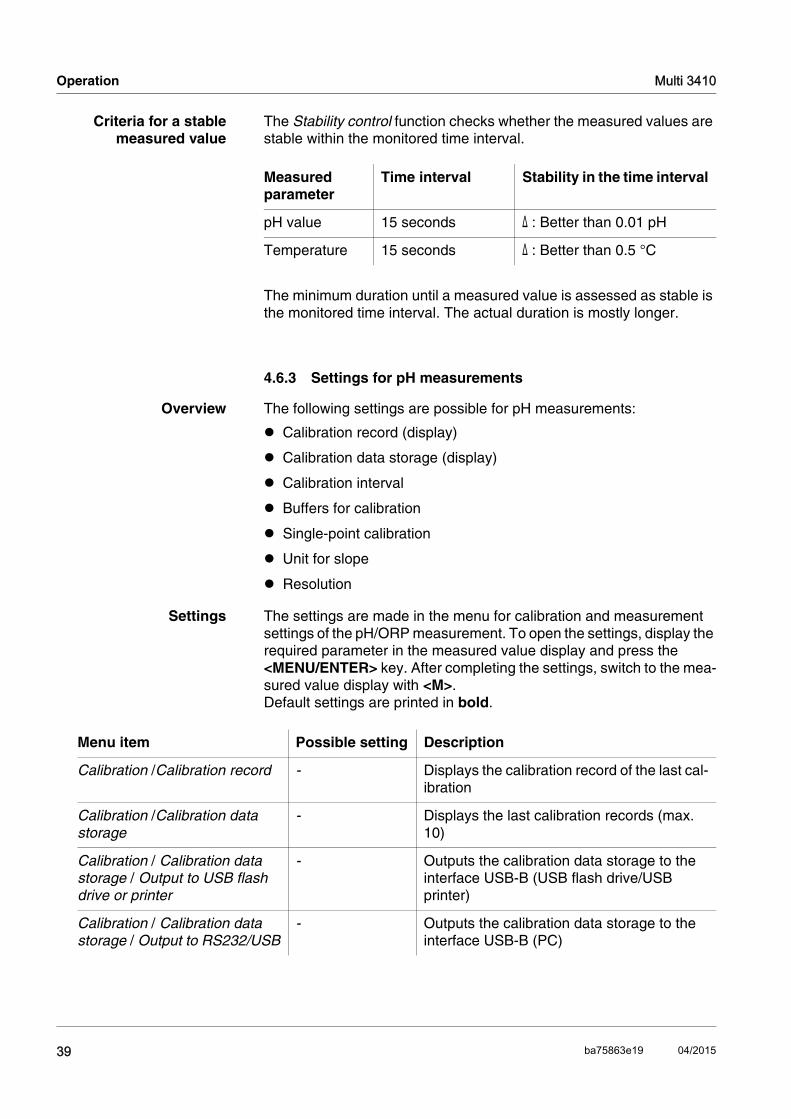
Criteria for a stablemeasured value
The Stability control function checks whether the measured values are stable within the monitored time interval.
The minimum duration until a measured value is assessed as stable is the monitored time interval. The actual duration is mostly longer.
4.6.3 Settings for pH measurements
Overview The following settings are possible for pH measurements:
Calibration record (display)
Calibration data storage (display)
Calibration interval
Buffers for calibration
Single-point calibration
Unit for slope
Resolution
Settings The settings are made in the menu for calibration and measurement settings of the pH/ORP measurement. To open the settings, display the required parameter in the measured value display and press the <MENU/ENTER> key. After completing the settings, switch to the mea-sured value display with <M>.Default settings are printed in bold.
Measured parameter
Time interval Stability in the time interval
pH value 15 seconds Δ : Better than 0.01 pH
Temperature 15 seconds Δ : Better than 0.5 °C
Menu item Possible setting Description
Calibration /Calibration record - Displays the calibration record of the last cal-ibration
Calibration /Calibration data storage
- Displays the last calibration records (max. 10)
Calibration / Calibration data storage / Output to USB flash drive or printer
- Outputs the calibration data storage to the interface USB-B (USB flash drive/USB printer)
Calibration / Calibration data storage / Output to RS232/USB
- Outputs the calibration data storage to the interface USB-B (PC)
39 ba75863e19 04/2015
Multi 3410 Operation
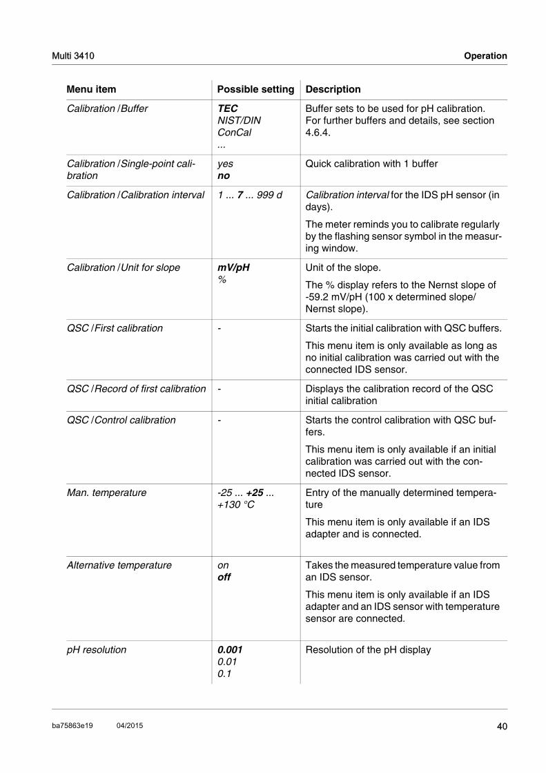
Calibration /Buffer TECNIST/DIN ConCal...
Buffer sets to be used for pH calibration.For further buffers and details, see section 4.6.4.
Calibration /Single-point cali-bration
yesno
Quick calibration with 1 buffer
Calibration /Calibration interval 1 ... 7 ... 999 d Calibration interval for the IDS pH sensor (in days).
The meter reminds you to calibrate regularly by the flashing sensor symbol in the measur-ing window.
Calibration /Unit for slope mV/pH%
Unit of the slope.
The % display refers to the Nernst slope of -59.2 mV/pH (100 x determined slope/Nernst slope).
QSC /First calibration - Starts the initial calibration with QSC buffers.
This menu item is only available as long as no initial calibration was carried out with the connected IDS sensor.
QSC /Record of first calibration - Displays the calibration record of the QSC initial calibration
QSC /Control calibration - Starts the control calibration with QSC buf-fers.
This menu item is only available if an initial calibration was carried out with the con-nected IDS sensor.
Man. temperature -25 ... +25 ... +130 °C
Entry of the manually determined tempera-ture
This menu item is only available if an IDS adapter and is connected.
Alternative temperature onoff
Takes the measured temperature value from an IDS sensor.
This menu item is only available if an IDS adapter and an IDS sensor with temperature sensor are connected.
pH resolution 0.0010.010.1
Resolution of the pH display
Menu item Possible setting Description
40ba75863e19 04/2015
Operation Multi 3410
4.6.4 pH calibration
Why calibrate? During the operation of an IDS pH sensor, the zero point (asymmetry) and slope of the sensor change with time.As a result, an inexact mea-sured value is displayed. Calibration determines the current values of the zero point and slope of the pH sensor and stores them in the mea-suring instrument. Thus, you should calibrate at regular intervals.
When do you have tocalibrate?
When the calibration interval has expired
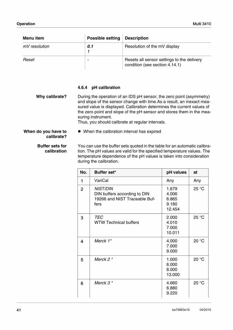
Buffer sets forcalibration
You can use the buffer sets quoted in the table for an automatic calibra-tion. The pH values are valid for the specified temperature values. The temperature dependence of the pH values is taken into consideration during the calibration.
mV resolution 0.11
Resolution of the mV display
Reset - Resets all sensor settings to the delivery condition (see section 4.14.1)
Menu item Possible setting Description
No. Buffer set* pH values at
1 VariCal Any Any
2 NIST/DINDIN buffers according to DIN 19266 and NIST Traceable Buf-fers
1.6794.0066.8659.18012.454
25 °C
3 TECWTW Technical buffers
2.0004.0107.00010.011
25 °C
4 Merck 1* 4.0007.0009.000
20 °C
5 Merck 2 * 1.0006.0008.00013.000
20 °C
6 Merck 3 * 4.6606.8809.220
20 °C
41 ba75863e19 04/2015

Multi 3410 Operation
7 Merck 4 * 2.0004.0007.00010.000
20 °C
8 Merck 5 * 4.0107.00010.000
25 °C
9 DIN 19267 1.0904.6506.7909.230
25 °C
10 Mettler Toledo USA * 1.6794.0037.00210.013
25 °C
11 Mettler Toledo EU * 1.9954.0057.0029.208
25 °C
12 Fisher * 2.0074.0027.00410.002
25 °C
13 Fluka BS * 4.0066.9848.957
25 °C
14 Radiometer * 1.6784.0057.0009.180
25 °C
15 Baker * 4.0066.99110.008
25 °C
16 Metrohm * 3.9967.0038.999
25 °C
17 Beckman * 4.0057.00510.013
25 °C
18 Hamilton Duracal * 4.0057.00210.013
25 °C
No. Buffer set* pH values at
42ba75863e19 04/2015

Operation Multi 3410
* Brand names or trade names are trademarks of their respective owners protected by law.
NoteThe buffers are selected in the menu, pH / <MENU/ENTER> / Calibra-tion / Buffer (see section 4.6.3).
Calibration points Calibration can be performed using one to five buffer solutions in any order (single-point to five-point calibration). The meter determines the following values and calculates the calibration line as follows:
19 Precisa * 3.9967.0038.999
25 °C
20 Reagecon TEC * 2.0004.0107.00010.000
25 °C
21 Reagecon 20 * 2.0004.0007.00010.00013.000
20 °C
22 Reagecon 25 * 2.0004.0007.00010.00013.000
25 °C
23 Chemsolute * 2.0004.0007.00010.000
20 °C
24 USABlueBook * 4.0007.00010.000
25 °C
25 YSI * 4.0007.00010.000
25 °C
No. Buffer set* pH values at
43 ba75863e19 04/2015

Multi 3410 Operation
NoteYou can display the slope in the units, mV/pH or % (see section 4.6.3).
Stability control The calibration procedure automatically activates the stability control function. The current measurement with stability control can be termi-nated at any time (accepting the current value).
Calibration record The new calibration values are displayed when a calibration procedure is completed.
Display calibration dataand output to interface
You can have the data of the last calibration displayed (see section 4.6.8). Subsequently, you can transmit the displayed calibration data to the interface, e. g. to a PC, with the <PRT> key.
NoteThe calibration record is automatically transmitted to the interface after calibrating.
Sample record
Determined values
Displayed calibration data
1-point Asy Zero point = Asy
Slope = Nernst slope (-59.2 mV/pH at 25 °C)
2-point AsySlp.
Zero point = Asy
Slope = Slp.
3-point to 5-point
AsySlp.
Zero point = Asy
Slope = Slp.
The calibration line is calculated by linear regression.
Multi 3410Ser. no. 09250023
CALIBRATION pHCalibration date 15.03.2014 16:13:33SenTix 940Ser. no. B092500013
TECBuffer 1 4.01Buffer 2 7.00Buffer 3 10.01Voltage 1 184.0 mV 24.0 °CVoltage 2 3.0 mV 24.0 °CVoltage 3 -177.0 mV 24.0 °CSlope -60.2 mV/pHAsymmetry 4.0 mVSensor +++
etc...
44ba75863e19 04/2015

Operation Multi 3410
Calibration evaluation After calibrating, the meter automatically evaluates the calibration. The zero point and slope are evaluated separately. The worse evaluation of both is taken into account. The evaluation appears on the display and in the calibration record.
NoteFor pH IDS sensors, you can optionally enable a more finely graded calibration evaluation (QSC) (see section 4.6.10).
Preparatory activities Perform the following preparatory activities when you want to calibrate:
4.6.5 Calibration interval
The calibration evaluation is displayed as a sensor symbol.
After the QSC function has been enabled the sensor symbol is replaced by the QSC color scale (see section 4.6.10).
After the specified calibration interval has expired, the sensor symbol
Display Calibration record
Zero point [mV]
Slope [mV/pH]
+++ -15 ... +15 -60.5 ... -58
++ -20 ... +20 -58 ... -57
+ -25 ... +25 -61 ... -60.5 or -57 ... -56
- -30 ... +30 -62 ... -61 or -56 ... -50
Clean the IDS sensor according to the sensor operating manual
Error Error < -30 or > 30
... -62 or
... -50
Eliminate the error according to chapter 6 WHAT TO DO IF...
1 Connect the IDS pH sensor to the meter.The pH measuring window is displayed.
2 Keep the buffer solutions ready.
45 ba75863e19 04/2015

Multi 3410 Operation
or the QSC color scale flashes. It is still possible to measure.
NoteTo ensure the high measuring accuracy of the measuring system, cal-ibrate after the calibration interval has expired.
Setting the calibrationinterval
The calibration interval is set to 7 days (d7) in the factory. You can change the interval (1 ... 999 days):
4.6.6 Carrying out an automatic calibration (AutoCal)
Make sure that in the sensor menu, Buffer menu, the buffer set is cor-rectly selected (see section 4.6.3).
Use any one to five buffer solutions of the selected buffer set in ascend-ing or descending order.
Below, calibration with Technical buffers (TEC) is described. When other buffer sets are used, other nominal buffer values are displayed. Apart from that, the procedure is identical.
NoteIf single-point calibration was set in the menu, the calibration procedure is automatically finished with the measurement of buffer solution 1 and the calibration record is displayed.
1 Open the menu for measurement settings with <MENU/ENTER>.
2 In the Calibration / Calibration interval menu, set the calibration interval with <><>.
3 Confirm the setting with <MENU/ENTER>.
4 Quit the menu with <M>.
1 In the measured value display, select the measured parameter pH or mV with <M>.
2 Start the calibration with <CAL>.The calibration display for the first buffer appears (voltage dis-play).
46ba75863e19 04/2015

Operation Multi 3410
NoteFor single-point calibration, the instrument uses the Nernst slope
3 Thoroughly rinse the IDS sensor with deionized water.
4 Immerse the IDS pH sensor in buffer solution 1.
5 For measurements without temperature sensor (e.g. when using an IDS adapter):Measure the temperature of the buffer manually and enter it with <><>.
6 Start the measurement with <MENU/ENTER>.The measured value is checked for stability (stability control).The [AR] status indicator is displayed. The measured parameter flashes.
7 Wait for the end of the measurement with stability control or accept the calibration value with <MENU/ENTER>. The calibration display for the next buffer appears (voltage dis-play).
8 If necessary, finish the calibration procedure as a single-point cal-ibration with <M>.The calibration record is displayed.
15.03.2014 08:00
15.03.2014 08:00
47 ba75863e19 04/2015
Multi 3410 Operation
(-59.2 mV/pH at 25 °C) and determines the zero point of the IDS pH sensor.
Continuing with two-point calibration
Continuing with three-to five-point calibration
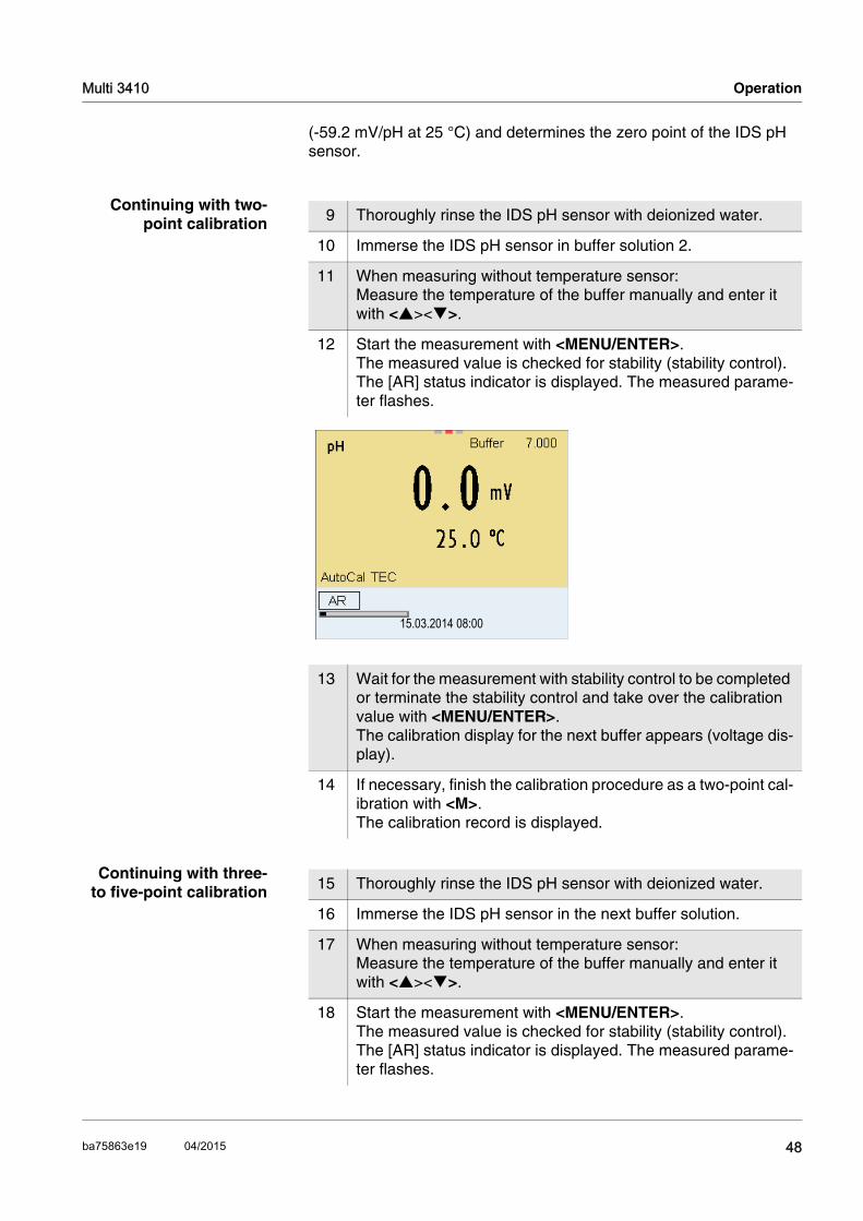
9 Thoroughly rinse the IDS pH sensor with deionized water.
10 Immerse the IDS pH sensor in buffer solution 2.
11 When measuring without temperature sensor:Measure the temperature of the buffer manually and enter it with <><>.
12 Start the measurement with <MENU/ENTER>.The measured value is checked for stability (stability control).The [AR] status indicator is displayed. The measured parame-ter flashes.
13 Wait for the measurement with stability control to be completed or terminate the stability control and take over the calibration value with <MENU/ENTER>. The calibration display for the next buffer appears (voltage dis-play).
14 If necessary, finish the calibration procedure as a two-point cal-ibration with <M>.The calibration record is displayed.
15.03.2014 08:00
15 Thoroughly rinse the IDS pH sensor with deionized water.
16 Immerse the IDS pH sensor in the next buffer solution.
17 When measuring without temperature sensor:Measure the temperature of the buffer manually and enter it with <><>.
18 Start the measurement with <MENU/ENTER>.The measured value is checked for stability (stability control).The [AR] status indicator is displayed. The measured parame-ter flashes.
48ba75863e19 04/2015

Operation Multi 3410
NoteCalibration is automatically completed after the last buffer of a buffer set has been measured. Then the calibration record is displayed.
The calibration line is determined by linear regression.
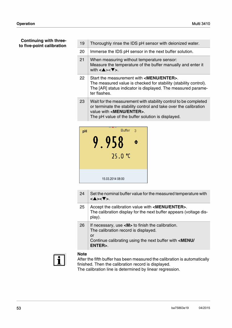
19 Wait for the measurement with stability control to be completed or terminate the stability control and take over the calibration value with <MENU/ENTER>. The calibration display for the next buffer appears (voltage dis-play).
20 If necessary, use <M> to finish the calibration.The calibration record is displayed. or Switch to calibration with the next buffer with <MENU/ENTER>.
15.03.2014 08:00
49 ba75863e19 04/2015
Multi 3410 Operation
4.6.7 Carrying out a manual calibration (ConCal)
Make sure that in the sensor menu, Buffer menu, the ConCal buffer set is correctly selected (see section 4.6.3).
Use any one to five buffer solutions in ascending or descending order.
NoteIf single-point calibration was set in the menu, the calibration procedure is automatically finished with the measurement of buffer solution 1 and the calibration record is displayed.
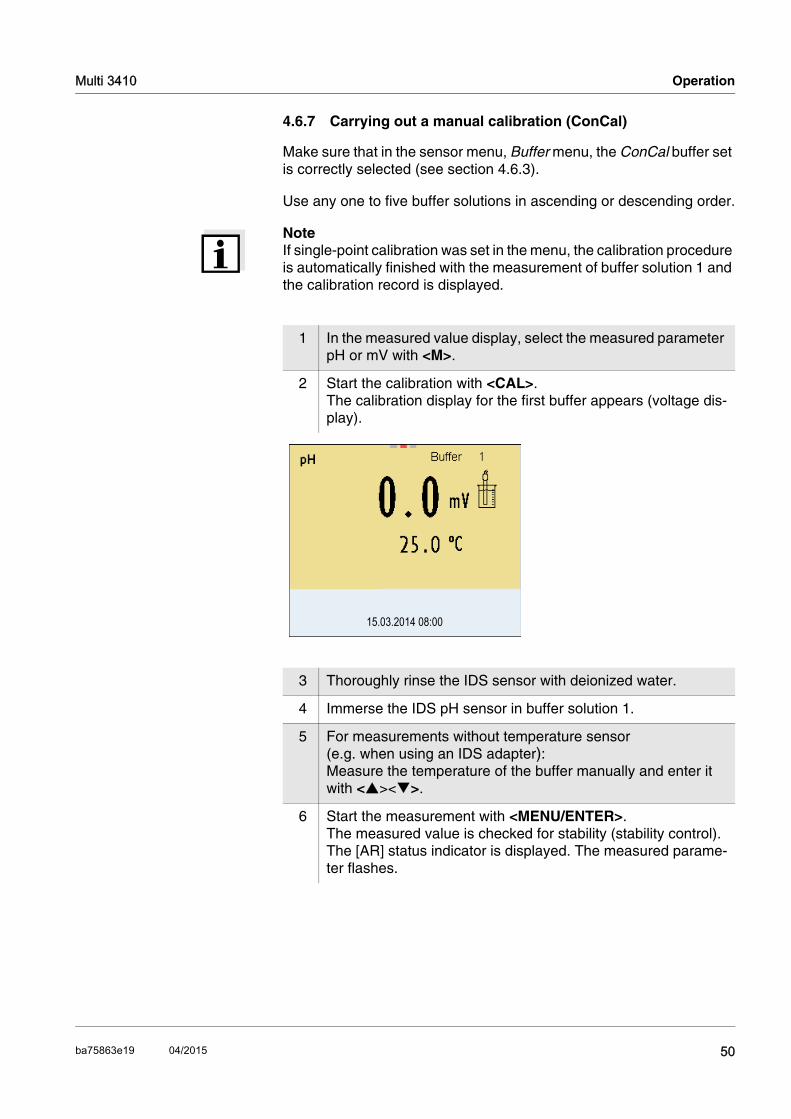
1 In the measured value display, select the measured parameter pH or mV with <M>.
2 Start the calibration with <CAL>.The calibration display for the first buffer appears (voltage dis-play).
3 Thoroughly rinse the IDS sensor with deionized water.
4 Immerse the IDS pH sensor in buffer solution 1.
5 For measurements without temperature sensor (e.g. when using an IDS adapter):Measure the temperature of the buffer manually and enter it with <><>.
6 Start the measurement with <MENU/ENTER>.The measured value is checked for stability (stability control).The [AR] status indicator is displayed. The measured parame-ter flashes.
15.03.2014 08:00
50ba75863e19 04/2015
Operation Multi 3410
NoteFor single-point calibration, the instrument uses the Nernst slope (-59.2 mV/pH at 25 °C) and determines the zero point of the IDS pH sensor.
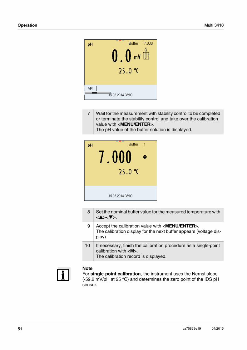
7 Wait for the measurement with stability control to be completed or terminate the stability control and take over the calibration value with <MENU/ENTER>. The pH value of the buffer solution is displayed.
8 Set the nominal buffer value for the measured temperature with <><>.
9 Accept the calibration value with <MENU/ENTER>. The calibration display for the next buffer appears (voltage dis-play).
10 If necessary, finish the calibration procedure as a single-point calibration with <M>.The calibration record is displayed.
15.03.2014 08:00
15.03.2014 08:00
51 ba75863e19 04/2015

Multi 3410 Operation
Continuing with two-point calibration 11 Thoroughly rinse the IDS sensor with deionized water.
12 Immerse the IDS pH sensor in buffer solution 2.
13 When measuring without temperature sensor:Measure the temperature of the buffer manually and enter it with <><>.
14 Start the measurement with <MENU/ENTER>.The measured value is checked for stability (stability control).The [AR] status indicator is displayed. The measured parame-ter flashes.
15 Wait for the measurement with stability control to be completed or terminate the stability control and take over the calibration value with <MENU/ENTER>. The pH value of the buffer solution is displayed.
16 Set the nominal buffer value for the measured temperature with <><>.
17 Accept the calibration value with <MENU/ENTER>. The calibration display for the next buffer appears (voltage dis-play).
18 If necessary, finish the calibration procedure as a two-point cal-ibration with <M>.The calibration record is displayed.
15.03.2014 08:00
52ba75863e19 04/2015
Operation Multi 3410
Continuing with three-to five-point calibration
NoteAfter the fifth buffer has been measured the calibration is automatically finished. Then the calibration record is displayed. The calibration line is determined by linear regression.
19 Thoroughly rinse the IDS pH sensor with deionized water.
20 Immerse the IDS pH sensor in the next buffer solution.
21 When measuring without temperature sensor:Measure the temperature of the buffer manually and enter it with <><>.
22 Start the measurement with <MENU/ENTER>.The measured value is checked for stability (stability control).The [AR] status indicator is displayed. The measured parame-ter flashes.
23 Wait for the measurement with stability control to be completed or terminate the stability control and take over the calibration value with <MENU/ENTER>. The pH value of the buffer solution is displayed.
24 Set the nominal buffer value for the measured temperature with <><>.
25 Accept the calibration value with <MENU/ENTER>. The calibration display for the next buffer appears (voltage dis-play).
26 If necessary, use <M> to finish the calibration.The calibration record is displayed. or Continue calibrating using the next buffer with <MENU/ENTER>.
15.03.2014 08:00
53 ba75863e19 04/2015

Multi 3410 Operation
4.6.8 Displaying calibration records
The calibration data can be displayed and then output to the interface.
Displaying thecalibration record
The calibration record of the last calibration is to be found under the menu item, Calibration / Calibration record. To open it in the measured value display, press the <CAL_> key.
The calibration records of the last 10 calibrations are to be found in the menu, Calibration / Calibration data storage / Display. To open the Cal-ibration menu, press the <MENU/ENTER> key in the measured value display.
Menu item Setting/function
Description
Calibration / Calibration data stor-age / Display
- Displays the calibration records.
Further options: Scroll through the calibra-
tion records with <><>.
Output the displayed cali-bration record to the inter-face with <PRT>.
Output all calibration records to the interface with <PRT_>.
Quit the display with <ESC>.
Switch directly to the mea-sured value display with <M>.
Calibration / Calibration data stor-age / Output to USB flash drive or printer
- Outputs the calibration data storage to the interface USB-B (USB flash drive/USB printer)
Calibration / Calibration data stor-age / Output to RS232/USB
- Outputs the calibration data storage to the interface USB-B (PC)
54ba75863e19 04/2015

Operation Multi 3410
4.6.9 Continuous measurement control (CMC function)
The Continuous Measurement Control (CMC function) facilitates to evaluate the current measured value instantly and definitely.
After each successful calibration the scale of the pH measuring range is displayed in the measured value display. Here you can very clearly see whether or not the current measured value is in the calibrated part of the measuring range.
The following information is displayed:
The limits of the calibrated range are determined by the buffers used for calibration:
1 Measuring range for which a valid calibration is available (back-ground color). Measured values in this range are suitable for documentation.
2 Measuring range for which no valid calibration is available (light gray). Measured values in this range are not suitable for docu-mentation. Calibrate the meter with buffers covering this mea-suring range.If the current measured value is not in the calibrated range, the color of this range changes to dark gray.If a measured value is outside the measuring range pH 0 - 14, overflow arrows are displayed at the left or right edge of the mea-suring range.
3 Currently measured pH value (needle)
4 Marking lines for all nominal buffer values used with the last valid calibration
Lower limit: Buffer with lowest pH value - 2 pH units Upper limit: Buffer with highest pH value + 2 pH units
1
2
3
4
15.03.2014 08:00Info
55 ba75863e19 04/2015

Multi 3410 Operation
4.6.10 QSC function (sensor quality control)
General informationon the QSC function
The QSC function (Quality Sensor Control) is a new sensor evaluation for digital IDS sensors. It evaluates the condition of an IDS pH sensor individually and with a very fine grading.
On the display, the QSC color scale (from green to yellow) indicates the current sensor evaluation by means of a pointer.
In the printout, the sensor evaluation is quoted as a percentage (1-100).
The finely graded sensor evaluation of the QSC function promptly calls your attention to changes of the sensor. Thus you can do what is necessary to restore the optimum measuring quality (e.g. clean, calibrate or replace the sensor).
Sensor evaluationwith / withoutQSC function
15.03.2014 08:00Info
QSC color scale
The double arrow on the color scale indi-cates the current sen-sor evaluation.
With QSC function Without QSC function (sensor symbol)
Very fine grading of the sensor evaluation (100 grades)
Rough grading of the sensor evaluation (4 grades)
The reference value is individu-ally determined for each sensor during the QSC initial calibra-tion.
A theoretical reference value is used for all sensors
Low tolerances for zero point and slope when using QSC buf-fer solutions
Greater tolerances for zero point and slope when using commer-cial buffer sets
Additional QSC calibration required (with special QSC buf-fer set)
No additional calibration required
56ba75863e19 04/2015

Operation Multi 3410
QSC calibration The QSC function is enabled by once carrying out an additional three-point calibration with special QSC buffer solutions. It covers the mea-suring range of the sensor from pH 2 to pH 11. The QSC initial calibra-tion determines the actual condition of the sensor and stores it as a reference in the sensor. To meet the high requirements of a QSC initial calibration, the QSC ini-tial calibration should optimally be carried out with the initial commis-sioning of the sensor.
Carry out the normal calibrations for your special measuring range with your usual standard solutions as previously done.
NoteAs soon as the QSC function was enabled for an IDS sensor, it is not possible to return to the sensor evaluation with the sensor symbol for this sensor.
Carrying out a QSCinitial calibration
NoteCarry out the QSC initial calibration very carefully. It determines the ref-erence value for the sensor. This reference value cannot be overwritten or reset.As soon as the QSC function was enabled, it is not possible to return to
1 Open the menu for measurement settings with <MENU/ENTER>.
2 In the QSC menu, select First calibration with <><>.The calibration display appears. AutoCal QSC-Kit is displayed as the buffer.Exclusively use the QSC-Kit for the QSC calibration. If you use other buffers, you will have no valid QSC calibration.
3 Calibration with the buffers of the QSC-Kit is done like a normal three-point calibration.Follow the user guide.
15.03.2014 08:00
57 ba75863e19 04/2015
Multi 3410 Operation
the sensor evaluation with the sensor symbol.
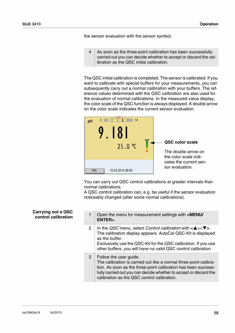
The QSC initial calibration is completed. The sensor is calibrated. If you want to calibrate with special buffers for your measurements, you can subsequently carry out a normal calibration with your buffers. The ref-erence values determined with the QSC calibration are also used for the evaluation of normal calibrations. In the measured value display, the color scale of the QSC function is always displayed. A double arrow on the color scale indicates the current sensor evaluation.
You can carry out QSC control calibrations at greater intervals than normal calibrations. A QSC control calibration can, e.g. be useful if the sensor evaluation noticeably changed (after some normal calibrations).
Carrying out a QSCcontrol calibration
4 As soon as the three-point calibration has been successfully carried out you can decide whether to accept or discard the cal-ibration as the QSC initial calibration.
15.03.2014 08:00Info
QSC color scale
The double arrow on the color scale indi-cates the current sen-sor evaluation.
1 Open the menu for measurement settings with <MENU/ENTER>.
2 In the QSC menu, select Control calibration with <><>.The calibration display appears. AutoCal QSC-Kit is displayed as the buffer.Exclusively use the QSC-Kit for the QSC calibration. If you use other buffers, you will have no valid QSC control calibration.
3 Follow the user guide.The calibration is carried out like a normal three-point calibra-tion. As soon as the three-point calibration has been success-fully carried out you can decide whether to accept or discard the calibration as the QSC control calibration.
58ba75863e19 04/2015

Operation Multi 3410
4.7 ORP voltage
4.7.1 General information
You can measure the following parameters:
ORP [mV]
NoteThe sensor connection and the USB-B (device) interface are galvani-cally isolated. This enables interference-free measurements in grounded measuring media.
Preparatory activities Perform the following preparatory activities when you want to measure:
4.7.2 Measuring the ORP
NoteIDS ORP sensors are not calibrated. However, you can check IDS ORP sensors using a test solution.
1 Connect the IDS ORP sensor to the meter.The ORP measuring window is displayed.
2 Check the meter with the IDS ORP sensor.
1 Perform the preparatory activities according to section 4.6.1.
2 Immerse the IDS ORP sensor in the test sample.
3 Select the mV display with <M>.
15.03.2014 08:00Info
59 ba75863e19 04/2015

Multi 3410 Operation
Stability control(AutoRead )
The stability control function (AutoRead) continually checks the stability of the measurement signal. The stability has a considerable impact on the reproducibility of measured values. The display of the measured parameter flashes until a stable measured value is available.
You can start the Stability control manually at any time, irrespective of the setting for automatic Stability control (see section 4.4.3) in the Sys-tem menu.
NoteYou can prematurely terminate the Stability control function manually with <MENU/ENTER> at any time. If the Stability control function is pre-maturely terminated, the current measurement data are output to the interface without the AutoRead info.
Criteria for a stablemeasured value
The Stability control function checks whether the measured values are stable within the monitored time interval.
The minimum duration until a measured value is assessed as stable is the monitored time interval. The actual duration is mostly longer.
1 Freeze the measured value with <AR>.The [HOLD] status indicator is displayed.
2 Using <MENU/ENTER>, activate the Stability control function manually.The [AR] status indicator appears while the measured value is assessed as not stable. A progress bar is displayed and the display of the measured parameter flashes.The [HOLD][AR] status indicator appears as soon as a stable measured value is recognized. The progress bar disappears and the display of the measured parameter stops flashing. The current measurement data is output to the interface. Mea-surement data meeting the stability control criterion is marked by AR.
3 Release the frozen measured value again with <AR> or <M>.The [AR] status display disappears. The display switches back to the previous indication.
Measured param-eter
Time interval Stability in the time inter-val
ORP voltage 15 seconds Δ : Better than 0.3 mV
Temperature 15 seconds Δ : Better than 0.5 °C
60ba75863e19 04/2015

Operation Multi 3410
4.7.3 Settings for ORP measurements
Overview The following settings are possible for ORP measurements:
Resolution
Automatic stability control
Settings The settings are made in the menu for measuring settings of the ORP measurement. To open the settings, display the required parameter in the measured value display and press the <MENU/ENTER> key. After completing the settings, switch to the measured value display with <M>.Default settings are printed in bold.
Menu item Possible set-ting
Description
mV resolution 0.11
Resolution of the mV dis-play
Reset - Resets all sensor settings to the delivery condition (see section 4.14.1)
61 ba75863e19 04/2015

Multi 3410 Operation
4.8 Dissolved oxygen
4.8.1 General information
You can measure the following parameters:
D.O. concentration
D.O. saturation index ("D.O. saturation")
D.O. partial pressure
NoteThe sensor connection and the USB-B (device) interface are galvani-cally isolated. This enables interference-free measurements in grounded measuring media.
Temperaturemeasurement
IDS D.O. sensors measure the temperature with a temperature sensor integrated in the IDS sensor.
Preparatory activities Perform the following preparatory activities when you want to measure:
NoteThe FDO® 925 needs to be calibrated in special cases only. Regular FDO® Checks are sufficient.
1 Connect the D.O. sensor to the meter. The D.O. measuring window is displayed.
2 Check or calibrate the meter with the sensor.
62ba75863e19 04/2015

Operation Multi 3410
4.8.2 Measuring
Selecting thedisplayed
measured parameter
You can switch between the following displays with <M>:
D.O. concentration [mg/l]
D.O. saturation [%]
D.O. partial pressure [mbar].
Salinity correction When measuring the concentration of solutions with a salt content of more than 1 g/l, a salinity correction is required. For this, you have to measure and input the salinity of the measured medium first.
When the salinity correction is switched on, the [SAL] indicator is dis-played in the measuring window.
NoteYou can switch the salinity correction on or off and enter the salinity in the menu for calibration and measurement settings (see section 4.9.4).
Freezing the measuredvalue (HOLD function)
With the HOLD function, you can freeze the current measured value. The displayed measured value stops changing until you switch the HOLD function off.
NoteIf the HOLD function is active, you can, e.g. start a manual measure-ment with stability control.
1 Perform the preparatory activities according to section 4.9.1.
2 Immerse the D.O. sensor in the test sample.
15.03.2014 08:00Info
1 Freeze the measured value with <AR>.The [HOLD] status indicator is displayed.
2 Release the frozen measured value again with <AR>.The HOLD function is switched off.The [HOLD] status display disappears.
63 ba75863e19 04/2015

Multi 3410 Operation
Stability control(AutoRead )
The stability control function (AutoRead) continually checks the stability of the measurement signal. The stability has a considerable impact on the reproducibility of measured values. The display of the measured parameter flashes until a stable measured value is available.
You can start a measurement with Stability control manually at any time, irrespective of the setting for automatic Stability control (see sec-tion 4.4.3) in the System menu.
NoteYou can prematurely terminate the Stability control function manually with <MENU/ENTER> at any time. If the Stability control function is pre-maturely terminated, the current measurement data are not output to the interface.
1 Freeze the measured value with <AR>.The [HOLD] status indicator is displayed.
2 Using <MENU/ENTER>, activate the Stability control function manually.The [AR] status indicator appears while the measured value is assessed as not stable. A progress bar is displayed and the display of the measured parameter flashes.The [HOLD][AR] status indicator appears as soon as a stable measured value is recognized. The progress bar disappears and the display of the measured parameter stops flashing. The current measurement data is output to the interface. Mea-surement data meeting the stability control criterion is marked by AR.
3 Using <MENU/ENTER>, start a further measurement with Sta-bility control.orRelease the frozen measured value again with <AR>.The display switches to the measured value display. The [AR][HOLD] status display disappears.
64ba75863e19 04/2015
Operation Multi 3410
Criteria for a stablemeasured value
The Stability control function checks whether the measured values are stable within the monitored time interval.
The minimum duration until a measured value is assessed as stable is the monitored time interval. The actual duration is mostly longer.
4.8.3 Settings for D.O. sensors (menu or measurement and calibration settings)
Overview The following settings are possible for D.O. sensors:
Calibration record (display)
Calibration data storage (display)
Calibration interval
FDO Check
Check interval
Salinity correction
Salinity (salinity equivalent)
Settings The settings are available in the menu for measurement and calibration settings. To open the settings, display the required parameter in the measured value display and press the <MENU/ENTER> key. After completing the settings, switch to the measured value display with <M>.
Measured parameter
Time interval Stability in the time interval
D.O. concen-tration
20 seconds Δ : Better than 0.03 mg/l
D.O. saturation 20 seconds Δ : Better than 0.4 %
D.O. partial pressure
20 seconds Δ : Better than 0.8 mbar
Temperature 15 seconds Δ : Better than 0.5 °C
Menu item Possible setting
Description
Calibration /Cali-bration record
- Displays the calibration record of the last calibration
Calibration /Cali-bration data storage
- Displays the last calibration records (max. 10)
65 ba75863e19 04/2015

Multi 3410 Operation
Calibration / Calibration data storage / Output to USB flash drive or printer
- Outputs the calibration data storage to a connected USB flash drive/USB printer
Calibration / Calibration data storage / Output to RS232/USB
- Outputs the calibration data storage to the interface
Calibration /Cali-bration interval
1 ... 180 ... 999 d
Calibration interval for the D.O. sen-sor (in days).
The meter reminds you to calibrate regularly by the flashing sensor sym-bol in the measuring window.
FDO Check /Start FDO Check
- Starts the FDO® Check.
FDO Check /Check interval
1 ... 60 ... 999 d
Interval for the FDO Check (in days).
The FDO Check status display indica-tor in the measuring window reminds you to check the sensor regularly.
Sal correction on off
Manual salt content correction for concentration measurements
Salinity 0.0 ... 70.0
Salinity or salinity equivalent for the salt content correction.
This function is only available for con-centration measurements if the man-ual salt content correction is switched on.
Menu item Possible setting
Description
66ba75863e19 04/2015

Operation Multi 3410
Response time t90
30 ... 300 Response time of the signal filter (in seconds).
A signal filter in the sensor reduces the fluctuation range of the measured value. The signal filter is character-ized by the response time t90. This is the time after which 90 % of a signal change is displayed.
This menu item is only available if sensor and meter support this func-tion.Firmware updates for the IDS sensor and the meter are provided on the internet (see chapter 9).
Reset - Resets all sensor settings to the deliv-ery condition (see section 4.14.1)
Menu item Possible setting
Description
67 ba75863e19 04/2015

Multi 3410 Operation
4.8.4 FDO® Check procedure (check of the FDO® 925)
Why should you checkthe sensor?
With the FDO® Check procedure, you can find out in a simple manner whether the FDO® 925 D.O. sensor should be cleaned or calibrated.
When should you checkthe sensor?
Checking can be useful in the following cases:
When the check interval has expired
If the measured values seem to be implausible
If you assume that the sensor cap is contaminated or at the end of its lifetime
After the sensor cap was exchanged
Routinely within the scope of company quality assurance measures.
FDO® Check procedure Check in water vapor-saturated air. Use the check and storage vessel to carry out the FDO® Check proce-dure.
Stability control(AutoRead)
The Stability control function (AutoRead) is automatically activated for the FDO® Check.
Carrying out the FDO®
Check procedureProceed as follows to carry out the FDO® Check procedure:
NoteThe sponge in the check and storage vessel must be moist (not wet). Leave the sensor in the check and storage vessel long enough so it can adapt to the ambient temperature.
1 Connect the D.O. sensor to the meter.
2 Place the D.O. sensor in the check and storage vessel.
3 In the measuring menu, start the FDO® Check procedure with FDO Check / Start FDO Check.The meter switches to the measured parameter, %.
15.03.2014 08:00
68ba75863e19 04/2015
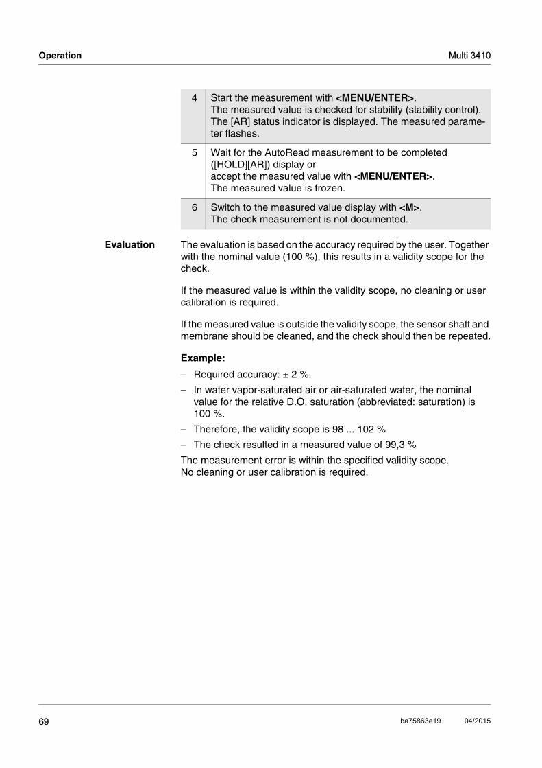
Operation Multi 3410
Evaluation The evaluation is based on the accuracy required by the user. Together with the nominal value (100 %), this results in a validity scope for the check.
If the measured value is within the validity scope, no cleaning or user calibration is required.
If the measured value is outside the validity scope, the sensor shaft and membrane should be cleaned, and the check should then be repeated.
Example:
– Required accuracy: ± 2 %.
– In water vapor-saturated air or air-saturated water, the nominal value for the relative D.O. saturation (abbreviated: saturation) is 100 %.
– Therefore, the validity scope is 98 ... 102 %
– The check resulted in a measured value of 99,3 %
The measurement error is within the specified validity scope.No cleaning or user calibration is required.
4 Start the measurement with <MENU/ENTER>.The measured value is checked for stability (stability control).The [AR] status indicator is displayed. The measured parame-ter flashes.
5 Wait for the AutoRead measurement to be completed ([HOLD][AR]) display or accept the measured value with <MENU/ENTER>.The measured value is frozen.
6 Switch to the measured value display with <M>.The check measurement is not documented.
69 ba75863e19 04/2015

Multi 3410 Operation
4.8.5 D.O. calibration
Why calibrate? D.O. sensors age. This changes the slope of the D.O. sensor. Calibra-tion determines the current slope of the sensor and stores this value in the instrument.
NoteThe FDO® 925 D.O. sensor ages so little it does not have to be regu-larly calibrated. To detect changes of the sensor as early as possible, the FDO® Check procedure can be useful (see section 4.8.4).
When to calibrate? If your evaluation of the FDO® Check procedure suggests a calibra-tion
When the calibration interval has expired
If your accuracy requirements are especially high
Routinely within the scope of company quality assurance measures.
Calibration procedures Calibration in water vapor-saturated air. To calibrate the FDO® 925 sensor, use the check and storage vessel.
Stability control(AutoRead)
In calibration, the Stability control function (AutoRead) is automatically activated.
Display calibration dataand output to interface
You can have the data of the last calibration displayed (see section 4.9.6). Subsequently, you can transmit the displayed calibration data to the interface, e. g. to a PC, with the <PRT> key.
NoteThe calibration record is automatically transmitted to the interface after calibrating.
Sample record
Calibration evaluation After the calibration, the meter automatically evaluates the current sta-tus of the calibration. The evaluation appears on the display and in the calibration record.
Multi 3410Ser. no. 10139695
CALIBRATION OxCalibration date 15.03.2014 16:13:33FDO 925Ser. no. 10146858
SC-FDO 925 10158765Relative slope 0.98Sensor +++
70ba75863e19 04/2015

Operation Multi 3410
Calibration evaluation ofthe FDO® 925
Calibration inwater vapor-saturated air
Proceed as follows to calibrate the D.O. sensor:
NoteThe sponge in the check and storage vessel must be moist (not wet). Leave the sensor in the check and storage vessel long enough so it can adapt to the ambient temperature.
Display Calibration record Relative slope
+++ S = 0.94 ... 1.06
++ S = 0.92 ... 0.94 orS = 1.06 ... 1.08
+ S = 0.90 ... 0.92 orS = 1.08 ... 1.10
Error Error S < 0.90 or S > 1.10
Eliminate the error according to chapter 6 WHAT TO DO IF...
1 Connect the D.O. sensor to the meter.
2 Place the FDO® 925 D.O. sensor into the check and storage vessel.
3 Start the calibration with <CAL>.The last calibration data (relative slope) is displayed.
15.03.2014 08:00
71 ba75863e19 04/2015

Multi 3410 Operation
4 Start the measurement with <MENU/ENTER>.The measured value is checked for stability (stability control).The [AR] status indicator is displayed. The measured parame-ter flashes.
5 Wait for the AutoRead measurement to be completed ([HOLD][AR]) display or accept the calibration value with <MENU/ENTER>.The calibration record is displayed and output to the interface.
6 Switch to the measured value display with <MENU/ENTER>.
72ba75863e19 04/2015

Operation Multi 3410
4.8.6 Displaying calibration records
The calibration data can be displayed and then output to the interface.
Displaying thecalibration record
The calibration record of the last calibration is available under the menu item, Calibration / Calibration record. To open it in the measured value display, press the <CAL_> key.
The calibration records of the last 10 calibrations are available in the menu, Calibration / Calibration data storage / Display. To open the Cal-ibration menu, press the <MENU/ENTER_> key in the measured value display.
Menu item Setting/function
Description
Calibration / Calibration data stor-age / Display
- Displays the calibration records.
Further options: Scroll through the calibra-
tion records with <><>.
Output the displayed cali-bration record to the inter-face with <PRT>.
Output all calibration records to the interface with <PRT_>.
Quit the display with <ESC>.
Switch directly to the mea-sured value display with <M>.
Calibration / Calibration data stor-age / Output to USB flash drive or printer
- Outputs the calibration data storage to the interface USB-B (USB flash drive/USB printer)
Calibration / Calibration data stor-age / Output to RS232/USB
- Outputs the calibration data storage to the interface USB-B (PC)
73 ba75863e19 04/2015

Multi 3410 Operation
4.9 Conductivity
4.9.1 General information
You can measure the following parameters:
Conductivity
Specific resistance
Salinity
Total dissolved solids (TDS)
NoteThe sensor connection and the USB-B (device) interface are galvani-cally isolated. This enables interference-free measurements in grounded measuring media.
Temperaturemeasurement
IDS sensors measure the temperature with a temperature sensor inte-grated in the IDS sensor.
Preparatory activities Perform the following preparatory activities when you want to measure:
4.9.2 Measuring
You can carry out conductivity measurements as follows:
1 Connect an IDS conductivity sensor to the meter. The conductivity measuring window is displayed.The Measuring cell and cell constant for the connected IDS conductivity sensor are automatically taken over.
1 Perform the preparatory activities according to section 4.9.1.
2 Immerse the IDS conductivity sensor in the test sample.
15.03.2014 08:00Info
74ba75863e19 04/2015

Operation Multi 3410
Selecting thedisplayed
measured parameter
You can switch between the following displays with <M>:
Conductivity [μS/cm] / [mS/cm]
Resistivity [Ω·cm] / [kΩ·cm] / [MΩ·cm]
Salinity SaL [ ]
Total dissolved solids TDS [mg/l] / [g/l]
The factor to calculate the total dissolved solids is set to 1.00 in the fac-tory. You can adjust this factor to meet your requirements in the range of 0.40 to 1.00. The factor is set in the menu for the parameter, TDS.
Freezing the measuredvalue (HOLD function)
With the HOLD function, you can freeze the current measured value. The displayed measured value stops changing until you switch the HOLD function off.
NoteIf the HOLD function is active, you can, e.g. start a manual measure-ment with stability control.
Stability control(AutoRead )
The stability control function (AutoRead) continually checks the stability of the measurement signal. The stability has a considerable impact on the reproducibility of measured values. The display of the measured parameter flashes until a stable measured value is available.
You can start the Stability control function manually at any time, irre-spective of the setting for automatic Stability control (see section 4.4.3) in the System menu.
1 Freeze the measured value with <AR>.The [HOLD] status indicator is displayed.
2 Release the frozen measured value again with <AR>.The HOLD function is switched off.The [HOLD] status display disappears.
1 Freeze the measured value with <AR>.The [HOLD] status indicator is displayed.
2 Using <MENU/ENTER>, activate the Stability control function manually.The [AR] status indicator appears while the measured value is assessed as not stable. A progress bar is displayed and the display of the measured parameter flashes.The [HOLD][AR] status indicator appears as soon as a stable measured value is recognized. The progress bar disappears and the display of the measured parameter stops flashing. The current measurement data is output to the interface. Mea-surement data meeting the stability control criterion is marked by AR.
75 ba75863e19 04/2015

Multi 3410 Operation
NoteYou can prematurely terminate the Stability control function manually with <MENU/ENTER> at any time. If the Stability control function is pre-maturely terminated, the current measurement data are output to the interface without the AutoRead info.
Criteria for a stablemeasured value
The Stability control function checks whether the measured values are stable within the monitored time interval.
The minimum duration until a measured value is assessed as stable is the monitored time interval. The actual duration is mostly longer.
3 Using <MENU/ENTER>, start a further measurement with Sta-bility control.orRelease the frozen measured value again with <AR>.The display switches to the measured value display. The [AR][HOLD] status display disappears.
Measured parameter
Time interval Stability in the time interval
Conductivity ϰ 10 seconds Δ : Better than 1.0% of measured value
Temperature 10 seconds Δ : Better than 0.5 °C
76ba75863e19 04/2015
Operation Multi 3410
4.9.3 Temperature compensation
The calculation of the temperature compensation is based on the pre-set reference temperature, 20 °C or 25 °C. It appears on the display as Tr20 or Tr25.
You can select one of the following temperature compensation meth-ods:
Nonlinear temperature compensation (nLF) according to EN 27 888
Linear temperature compensation (Lin) with adjustable coeffi-cients of 0.000 ... 10.000 %/K
No temperature compensation (off)
NoteThe reference temperature and temperature compensation are set in the menu for the parameter, conductivity (see section 4.9.4).
Application tips Select the following temperature compensations given in the table according to the respective test sample:
Test sample Temperature compensation Display indicator
Natural water (ground water, surface water, drinking water)
nLF according to EN 27 888
nLF
Ultrapure water nLF according to EN 27 888
nLF
Other aqueous solu-tions
lin Set linear temperature coefficient0.001 ... 10.000 %/K
lin
Salinity (seawater) Automatic nLF according to IOT (International Oceanogra-phic Tables
Sal, nLF
77 ba75863e19 04/2015

Multi 3410 Operation
4.9.4 Settings for IDS conductivity sensors
Overview The following settings are possible for IDS conductivity sensors:
Calibration record (display)
Calibration data storage (display)
Calibration interval
Reference temperature
Temperature compensation
TDS factor
Unit of the temperature
Settings The settings are made in the menu for the measured parameter, con-ductivity. To open the settings, display the required parameter in the measured value display and press the <MENU/ENTER> key. After completing the settings, switch to the measured value display with <M>.The possible settings are individually displayed for each sensor. Below the setting menu is displayed for two IDS sensors (TetraCon 925, LR 925/01).Default settings are printed in bold.
Setting menu ofTetraCon 925
Menu item Possible setting
Description
Calibration /Cali-bration record
- Displays the calibration record of the last calibration
Calibration /Cali-bration data stor-age
- Displays the last calibration records (max. 10)
Calibration / Calibration data storage / Output to USB flash drive or printer
- Outputs the calibration data stor-age to a connected USB flash drive/USB printer
Calibration /Cali-bration interval
1 ... 150 ... 999 d
Calibration interval for the IDS conductivity sensor (in days).
The meter reminds you to cali-brate regularly by the flashing sensor symbol in the measuring window.
78ba75863e19 04/2015

Operation Multi 3410
Type Measuring cell used
Cal Measuring cells whose cell con-stant is determined by calibration in the KCL control standard solu-tion.Calibration range:0.450 to 0.500 cm-1 The currently valid cell constant is displayed in the status line.
man Freely adjustable cell constant in the range 0.450 ... 0.500 cm-1.
Man. cell const. 0.450 ... 0.475 ... 0.500 cm-1
The cell constant and be dis-played and set here
Temp. comp. (TC) / Method
nLFLinoff
Procedure for temperature com-pensation (see section 4.9.3).
This setting is only available for the measured parameters, ϰ and ρ.
Temp. comp. (TC) / Linear coeff.
0.000 ... 2.000 ... 10.000 %/K
Coefficient of the linear tempera-ture compensation.
This setting is only available when the linear temperature compensation is set.
Temp. comp. (TC) / Reference temp.
20 °C25 °C
Reference temperature
This setting is only available for the measured parameters, ϰ and ρ.
TDS factor 0.40 ... 1.00 Factor for TDS value
Reset - Resets all sensor settings to the delivery condition (see section 4.14.1)
Menu item Possible setting
Description
79 ba75863e19 04/2015
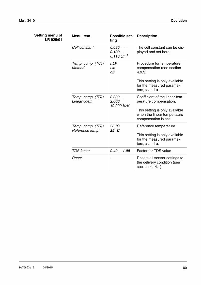
Multi 3410 Operation
Setting menu ofLR 925/01
Menu item Possible set-ting
Description
Cell constant 0.090 ... ... 0.100 ... 0.110 cm-1
The cell constant can be dis-played and set here
Temp. comp. (TC) / Method
nLFLinoff
Procedure for temperature compensation (see section 4.9.3).
This setting is only available for the measured parame-ters, ϰ and ρ.
Temp. comp. (TC) / Linear coeff.
0.000 ... 2.000 ... 10.000 %/K
Coefficient of the linear tem-perature compensation.
This setting is only available when the linear temperature compensation is set.
Temp. comp. (TC) / Reference temp.
20 °C25 °C
Reference temperature
This setting is only available for the measured parame-ters, ϰ and ρ.
TDS factor 0.40 ... 1.00 Factor for TDS value
Reset - Resets all sensor settings to the delivery condition (see section 4.14.1)
80ba75863e19 04/2015

Operation Multi 3410
4.9.5 Determining the cell constant (calibration in control standard)
Why determine the cellconstant?
Aging slightly changes the cell constant, e. g. due to coatings. As a result, an inexact measured value is displayed. The original character-istics of the cell can often be restored by cleaning the cell. Calibration determines the current value of the cell constant and stores this value in the meter. Thus, you should calibrate at regular intervals (we recom-mend: every 6 months).
Procedure You can determine the actual cell constant of the IDS conductivity sen-sor cell by calibrating with the control standard in the following range:
0.450 ... 0.500 cm-1 (e.g. TetraCon 925, nominal cell constant 0.475)
The cell constant is determined in the control standard, 0.01 mol/l KCl.
In the delivery condition, the calibrated cell constant of the IDS sensor is set to 0.475 cm-1 (conductivity measuring cell, TetraCon 925).
Stability control(AutoRead)
In calibration, the Stability control function (AutoRead) is automatically activated.
Display calibration dataand output to interface
You can have the data of the last calibration displayed (see section 4.9.6). Subsequently, you can transmit the displayed calibration data to the interface, e. g. to a PC, with the <PRT> key.
NoteThe calibration record is automatically transmitted to the interface after calibrating.
Sample record
Calibration evaluation After calibration, the meter automatically evaluates the current status of the calibration. The evaluation appears on the display and in the cali-bration record.
Multi 3410Ser. no. 09250023
CALIBRATION CondCalibration date 15.03.2014 16:13:33TetraCon 925Ser. no. 09250033
Cell constant 0.476 1/cm 25.0 °CSensor +++
Display Calibration record
Cell constant [cm-1]
+++ Within the range0.450 ... 0.500 cm-1
81 ba75863e19 04/2015
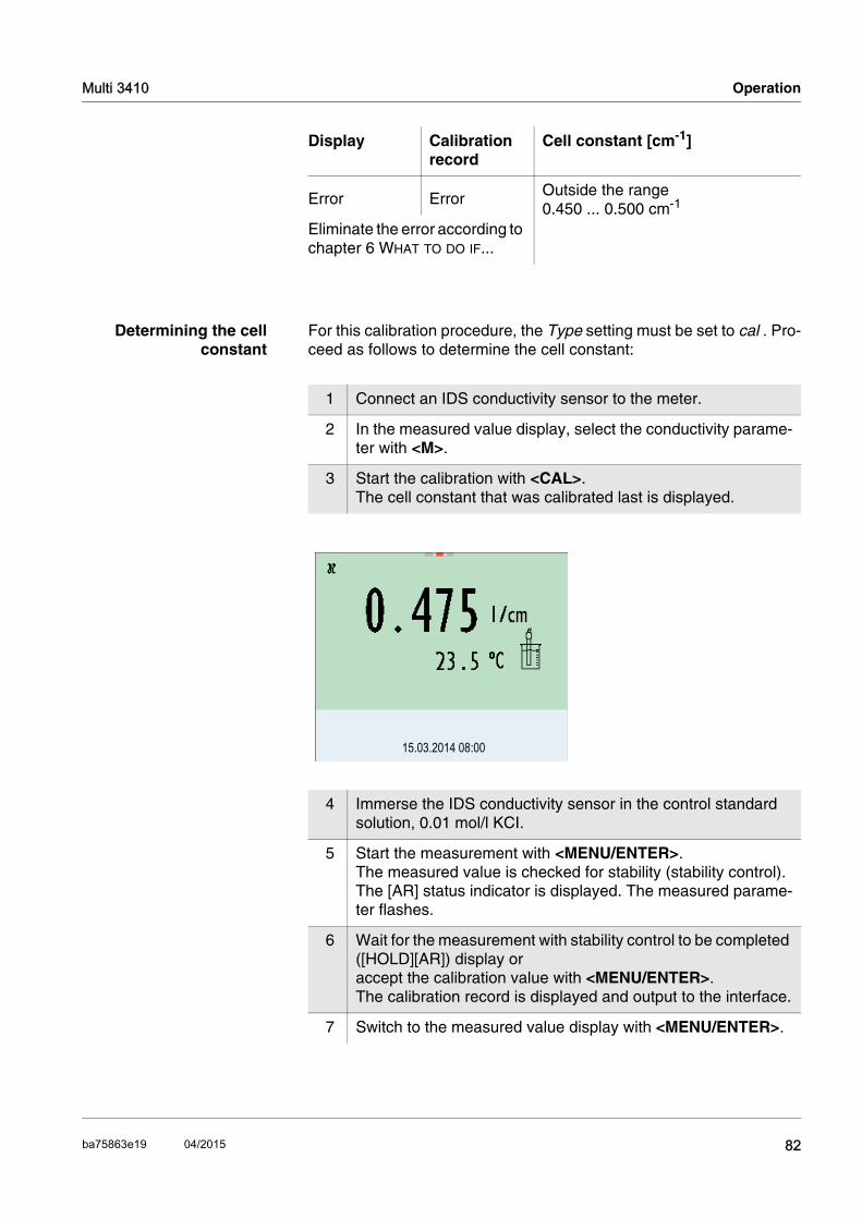
Multi 3410 Operation
Determining the cellconstant
For this calibration procedure, the Type setting must be set to cal . Pro-ceed as follows to determine the cell constant:
Error Error Outside the range0.450 ... 0.500 cm-1
Eliminate the error according to chapter 6 WHAT TO DO IF...
Display Calibration record
Cell constant [cm-1]
1 Connect an IDS conductivity sensor to the meter.
2 In the measured value display, select the conductivity parame-ter with <M>.
3 Start the calibration with <CAL>.The cell constant that was calibrated last is displayed.
4 Immerse the IDS conductivity sensor in the control standard solution, 0.01 mol/l KCI.
5 Start the measurement with <MENU/ENTER>.The measured value is checked for stability (stability control).The [AR] status indicator is displayed. The measured parame-ter flashes.
6 Wait for the measurement with stability control to be completed ([HOLD][AR]) display or accept the calibration value with <MENU/ENTER>.The calibration record is displayed and output to the interface.
7 Switch to the measured value display with <MENU/ENTER>.
15.03.2014 08:00
82ba75863e19 04/2015

Operation Multi 3410
4.9.6 Displaying calibration records
The calibration data can be displayed and then output to the interface.
Displaying thecalibration record
The calibration record of the last calibration is to be found under the menu item, Calibration / Calibration record. To open it in the measured value display, press the <CAL_> key.
The calibration records of the last 10 calibrations are to be found in the menu, Calibration / Calibration data storage / Display. To open the Cal-ibration menu, press the <MENU/ENTER> key in the measured value display.
Menu item Setting/function
Description
Calibration / Calibration data storage / Display
- Displays the calibration records.
Further options: Scroll through the calibra-
tion records with <><>.
Output the displayed cali-bration record to the inter-face with <PRT>.
Output all calibration records to the interface with <PRT_>.
Quit the display with <ESC>.
Switch directly to the mea-sured value display with <M>.
Calibration / Calibration data storage / Output to USB flash drive or printer
- Outputs the calibration data storage to the interface USB-B (USB flash drive/USB printer)
Calibration / Calibration data storage / Output to RS232/USB
- Outputs the calibration data storage to the interface USB-B (PC)
83 ba75863e19 04/2015

Multi 3410 Operation
4.10 Turbidity measurement (VisoTurb® 900-P)
4.10.1 General information
Measured parameters You can measure the following parameters:
FNU
NTU
NoteThe sensor connection and the USB-B (device) interface are galvani-cally isolated. This facilitates interference-free measurements also in grounded measuring media.
The sensor connection and the USB-B (device) interface are galvani-cally isolated. This facilitates interference-free measurements also in the following cases:
Measurement in grounded test samples
Measurement with several sensors connected to one Multi 3410 in one test sample
Preparatory activities Avoid gas bubbles (e.g. air bubbles) in the test sample.
Use suitable vessels for measurement and calibration (see operating manual of the VisoTurb® 900-P sensor).
Heed the minimum depth of immersion for the sensor
Perform the following preparatory activities when you want to measure:
1 Connect a turbidity sensor to the measuring instrument. The turbidity measuring screen is displayed.The data for the connected IDS turbidity sensor are automati-cally taken over.
2 Fill the test sample into a lightproof measuring vessel up to a level of at least 8 cm.
3 When immersing the sensor in the test sample, hold the sensor at an angle.
4 For measuring, position the sensor upright.
5 Position the sensor in a way that meets the following require-ments. Distance to the bottom: 6 cm
Distance to the walls of the vessel: 2 cm
Minimum depth of immersion: 2 cm
84ba75863e19 04/2015

Operation Multi 3410
NoteTo position the sensor optimally and permanently while it is measuring, fix it on a support.
4.10.2 Measuring
You can carry out turbidity measurements as follows:
Selecting thedisplayed
measured parameter
You can switch between the following displays with <M>:
Turbidity [FNU]
Turbidity [NTU]
Freezing the measuredvalue (HOLD function)
With the HOLD function, you can freeze the current measured value. The displayed measured value stops changing until you switch the HOLD function off.
NoteIf the HOLD function is active, you can, e.g. start a manual measure-ment with stability control.
Stability control(AutoRead )
The stability control function (AutoRead) continually checks the stability of the measurement signal. The stability has a considerable impact on the reproducibility of measured values. The display of the measured
1 Perform the preparatory activities according to section 4.10.1.
2 Immerse the sensor in the test sample at an angle and then position it in the measuring vessel (see section 4.10.1).
30.09.2012 08:00Info
1 Freeze the measured value with <AR>.The [HOLD] status indicator is displayed.
2 Release the frozen measured value again with <AR>.The HOLD function is switched off.The [HOLD] status display disappears.
85 ba75863e19 04/2015

Multi 3410 Operation
parameter flashes until a stable measured value is available.
Irrespective of the setting for automatic Stability control (see section 4.4.3) in the System menu, you can start the Stability control function manually at any time.
NoteYou can prematurely terminate the Stability control function manually with <MENU/ENTER> at any time. If the Stability control function is pre-maturely terminated, the current measurement data are output to the interface without the AutoRead info.
Criteria for a stablemeasured value
The Stability control function checks whether the measured values are stable within the monitored time interval.
The minimum duration until a measured value is assessed as stable is the monitored time interval. The actual duration is mostly longer.
4.10.3 Settings for turbidity sensors
1 Freeze the measured value with <AR>.The [HOLD] status indicator is displayed.
2 Using <MENU/ENTER>, activate the Stability control function manually.The [AR] status indicator appears while the measured value is assessed as not stable. A progress bar is displayed and the display of the measured parameter flashes.The [HOLD][AR] status indicator appears as soon as a stable measured value is recognized. The progress bar disappears and the display of the measured parameter stops flashing. The current measurement data are output to the interface. Measurement data meeting the stability control criterion are marked by AR.
3 Using <MENU/ENTER>, start a further measurement with Sta-bility control.orRelease the frozen measured value again with <AR>.The display switches to the measured value display. The [AR][HOLD] status display disappears.
Measured parameter
Time interval Stability in the time interval
Turbidity (FNU/NTU)
15 seconds Δ : better than 1.0% of measured value
86ba75863e19 04/2015

Operation Multi 3410
Settings The settings are made in the menu for the measured parameter, turbid-ity. To open the settings, display the required measured parameter in the measured value display and press the <MENU/ENTER> key. After completing the settings, switch to the measured value display with <M>.The possible settings are individually displayed for each sensor. Default settings are printed in bold.
Setting menuVisoTurb® 900-P
4.10.4 Calibration
Why calibrate? The calibration line of the sensor is determined and stored through cal-ibrating.
When to calibrate? When the calibration interval has expired
at regular intervals
Menu item Possible setting
Explanation
Calibration / Calibration record
- Displays the calibration record of the last calibration.
Calibration / Calibration data storage / Display
- Displays the last calibration records (max. 10)
Calibration / Calibration data storage / Output to USB flash drive or printer
- Outputs the stored calibration data to a connected USB mem-ory device/USB printer)
Calibration / Calibration data storage / Output to RS232/USB
- Outputs the calibration data storage to the interface
Calibration / Calibration interval
1 ... 30 ... 999 d
Calibration interval for the tur-bidity sensor (in days).
The meter reminds you to cali-brate regularly by the flashing sensor symbol in the measuring screen.
Resolution 0.11
Resolution of the FNU/NTU dis-play
Reset - Resets all sensor settings to the delivery condition (see section 4.14.1).
87 ba75863e19 04/2015
Multi 3410 Operation
Calibration standards Calibrate with 1 to 3 turbidity standard solutions. The standard solu-tions must be selected in the following order.
The turbidity expected in the measurement dictates the number and selection of the standards. Calibration has to be carried out for the range with the highest turbidity to be expected and for all lower ranges. The standard solutions for this have to be selected in ascending order, starting with standard 1.
Example:If you expect turbidity values in the range 200 ... 4000 FNU/NTU, you have to carry out a 3-point calibration.
The measurement precision is also dependent on the selected stan-dard solutions. Therefore, the selected standard solutions should cover the value range expected of the turbidity measurement.
If the measured turbidity is outside the measurement range, OFL is dis-played.
Standard solution Range (FNU/NTU)
1 0.0 ... 1.0
2 5.0 ... 200.0
3 200.0 ... 4000.0
As the standard with turbidity value 0.0 FNU you can use clean tap water or filtered, deionized water in a suitable cal-ibration vessel, depending on the required quality (see sec-tion 4.10.1). This standard should be freshly prepared prior to every calibration. Suitable bottles are listed in the price list of the WTW catalog "Lab and field instrumentation“.
Standards with turbidity values for the calibration ranges 2 and 3 are available as accessories (see price list of the WTW catalog "Lab and field instrumentation“). Calibration can be carried out in the bottles the standards are deliv-ered in. The standards can be used several times within their shelf life.
Replace the standards solutions if you have any doubts concerning their quality or after the expiration date.
1 Perform the preparatory activities according to section 4.10.1.
2 Connect the turbidity sensor to the measuring instrument.The turbidity measuring screen is displayed.
3 Keep the standard solutions ready in suitable calibration ves-sels.
88ba75863e19 04/2015

Operation Multi 3410
Continuing with two-point calibration
4 In the measured value display, select the TRB measuring win-dow with <> <> and <M>.
5 Start the calibration with <CAL>.The calibration display appears.
6 Thoroughly rinse the turbidity sensor with distilled water and dry it with a lint-free cloth.
7 Immerse the turbidity sensor in the test sample at an angle.
8 Position the turbidity sensor in the measuring vessel (see sec-tion 4.10.1).
9 Use <> <> and <><> to set the concentration of the standard solution for each digit and confirm with <MENU/ENTER>.The standard solution is measured.The measured value is checked for stability (AutoRead).
10 Wait for the end of the AutoRead measurement. The calibration display for the next standard solution appears.
15.09.2014 08:00
0.0 FNU
Standard 1
Cal
15.09.2014 08:00
124.0 FNU
Standard 2
Cal
11 Thoroughly rinse the turbidity sensor with distilled water and dry it with a lint-free cloth.
89 ba75863e19 04/2015

Multi 3410 Operation
Continuing with three-point calibration
Repeat the steps 11 to 15 with the third standard solution. The new cal-ibration values are displayed after the last calibration step was com-pleted.
4.10.5 Calibration data
Displays the calibrationdata
The calibration record of the last calibration is to be found under the menu item, <MENU/ENTER> / Calibration / / Calibration record. To open it, press the <CAL_> key in the measured value display.
The calibration records of the last 10 calibrations are to be found in the menu, Calibration / Calibration data storage / Display. To open the Cal-ibration menu, press the <MENU/ENTER> key in the measured value display.
12 Immerse the turbidity sensor in the test sample at an angle.
13 Position the turbidity sensor in the measuring vessel (see sec-tion 4.10.1).
14 Use <> <> and <><> to set the concentration of the standard solution for each digit and confirm with <MENU/ENTER>.The standard solution is measured.The measured value is checked for stability (AutoRead).
15 Wait for the end of the AutoRead measurement. The calibration display for the next standard solution appears.
16 If necessary, terminate the calibration as a two-point calibration with <M>.The new calibration values are displayed.orContinue with three-point calibration.
15.09.2014 08:00
1010.0 FNU
Standard 3
Cal
90ba75863e19 04/2015

Operation Multi 3410
Calibration evaluation After calibrating, the meter automatically evaluates the calibration.
Menu item Setting/function
Explanation
Calibration / Calibration data storage / Display
- Displays the calibration record.
Further options: Scroll through the cali-
bration records with <><>.
Output the displayed cal-ibration record to the interface with <PRT>.
Output all calibration records to the interface with <PRT_>.
Quit the display with <ESC> or <MENU/ENTER>.
Switch directly to the measured value display with <M>.
Calibration / Calibration data storage / Output to RS232/USB
- Outputs the calibration records to the interface.
Display Calibration record
Explanation
+++ Optimum calibration
Good calibration
91 ba75863e19 04/2015

Multi 3410 Operation
Calibration record(example)
Multi 3410Ser. no. 12345678
CALIBRATION TRB:VisoTurb 900-PSer. no. 14E99900318.09.2014 08:09:10
# 1 0.0 FNU# 2 124.0 FNUSensor +++_____________________________________
92ba75863e19 04/2015

Operation Multi 3410
4.11 Data storage
You can transmit measured values (datasets) to the data storage:
Manual storage (see section 4.11.1)
Automatic storage at intervals (see section 4.11.2)
Each storage process transmits the current dataset to the interface at the same time.
Measurement dataset A complete dataset consists of:
Date/time
Meter name, series number
Sensor name, series number
ID number
Measured value of the connected sensor
Measured temperature value of the connected sensor
AutoRead info: AR appears with the measured value if the AutoRead criterion was met while storing (stable measured value). Otherwise, the AR display is missing.
Calibration evaluation: - 4 levels (+++, ++, +, -, or no evaluation) or- QSC (percentage)
Storage locations The Multi 3410 meter has two measurement data memories. The mea-sured values recorded either manually or automatic are stored sepa-rately in individual measurement data memories.
Storage Maximum number of datasets
Manual data storage 500
Automatic data storage 10000
93 ba75863e19 04/2015
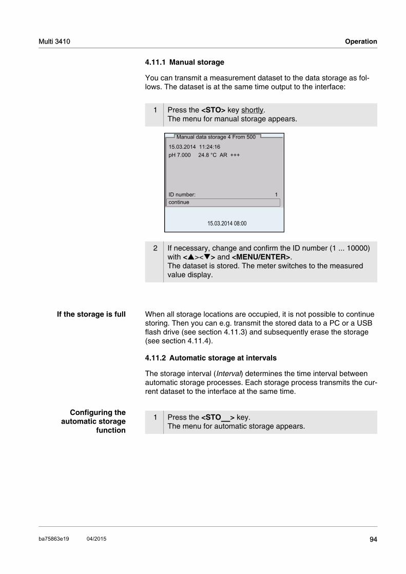
Multi 3410 Operation
4.11.1 Manual storage
You can transmit a measurement dataset to the data storage as fol-lows. The dataset is at the same time output to the interface:
If the storage is full When all storage locations are occupied, it is not possible to continue storing. Then you can e.g. transmit the stored data to a PC or a USB flash drive (see section 4.11.3) and subsequently erase the storage (see section 4.11.4).
4.11.2 Automatic storage at intervals
The storage interval (Interval) determines the time interval between automatic storage processes. Each storage process transmits the cur-rent dataset to the interface at the same time.
Configuring theautomatic storage
function
1 Press the <STO> key shortly.The menu for manual storage appears.
2 If necessary, change and confirm the ID number (1 ... 10000) with <><> and <MENU/ENTER>.The dataset is stored. The meter switches to the measured value display.
15.03.2014 11:24:16
pH 7.000 24.8 °C AR +++
ID number: 1continue
Manual data storage 4 From 500
15.03.2014 08:00
1 Press the <STO_> key.The menu for automatic storage appears.
94ba75863e19 04/2015

Operation Multi 3410
Settings You can configure the automatic storage function with the following set-tings:
Starting the automaticstorage function
To start the automatic storage function, select continue with <><> and confirm with <MENU/ENTER>. The meter switches to the mea-sured value display.
ID number 1Interval 30 sDuration 180 mincontinue
0d03h00min
0 1d17h33min
Automatic data storage
15.03.2014 08:00
Set entire storing dura-tion
Max. available storing duration
Graphical display of the storage usage
Menu item Possible setting
Description
ID number 1 ... 10000 ID number for the dataset series
Interval 1 s, 5 s, 10 s, 30 s, 1 min, 5 min, 10 min, 15 min, 30 min, 60 min
Storage interval.
The lower limit of the storage interval can be restricted by the number of free storage locations.The upper limit is restricted by the stor-age duration.
Duration 1 min ... x min
Storage duration.Specifies after which time the auto-matic storage should be terminated.
The lower limit of the storage duration is restricted by the storage interval.The upper limit is restricted by the number of free storage locations.
95 ba75863e19 04/2015

Multi 3410 Operation
The active automatic storage function can be recognized by the prog-ress bar in the status line. The progress bar indicates the remaining storing duration.
NoteIf the automatic storage function is activated, only the following keys are active: <M>, <STO_> and <On/Off>. The other keys and the automatic switch-off function are deactivated.
Terminating theautomatic storage
function prematurely
Proceed as follows to switch off the automatic storage function before the adjusted storage duration has expired:
15.03.2014 08:00
0d03h00min
Remaining storing duration
Graphical display of the storing duration
1 Press the <STO_> key.The following window appears.
2 Using <><>, select yes and confirm with <MENU/ENTER>.The meter switches to the measured value display.The automatic storage function is terminated.
Stop automatic storage?
yesno
Warning
15.03.2014 08:00
96ba75863e19 04/2015
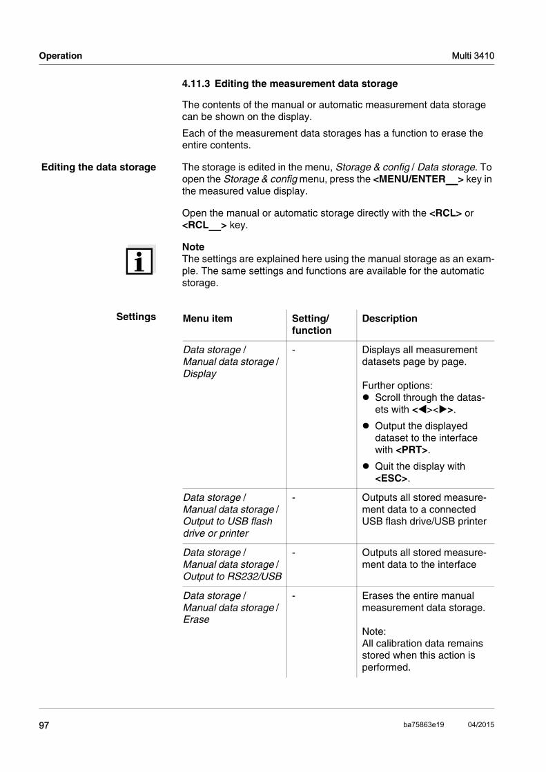
Operation Multi 3410
4.11.3 Editing the measurement data storage
The contents of the manual or automatic measurement data storage can be shown on the display.
Each of the measurement data storages has a function to erase the entire contents.
Editing the data storage The storage is edited in the menu, Storage & config / Data storage. To open the Storage & config menu, press the <MENU/ENTER_> key in the measured value display.
Open the manual or automatic storage directly with the <RCL> or <RCL_> key.
NoteThe settings are explained here using the manual storage as an exam-ple. The same settings and functions are available for the automatic storage.
Settings Menu item Setting/function
Description
Data storage / Manual data storage / Display
- Displays all measurement datasets page by page.
Further options: Scroll through the datas-
ets with <><>.
Output the displayed dataset to the interface with <PRT>.
Quit the display with <ESC>.
Data storage / Manual data storage / Output to USB flash drive or printer
- Outputs all stored measure-ment data to a connected USB flash drive/USB printer
Data storage / Manual data storage / Output to RS232/USB
- Outputs all stored measure-ment data to the interface
Data storage / Manual data storage / Erase
- Erases the entire manual measurement data storage.
Note:All calibration data remains stored when this action is performed.
97 ba75863e19 04/2015
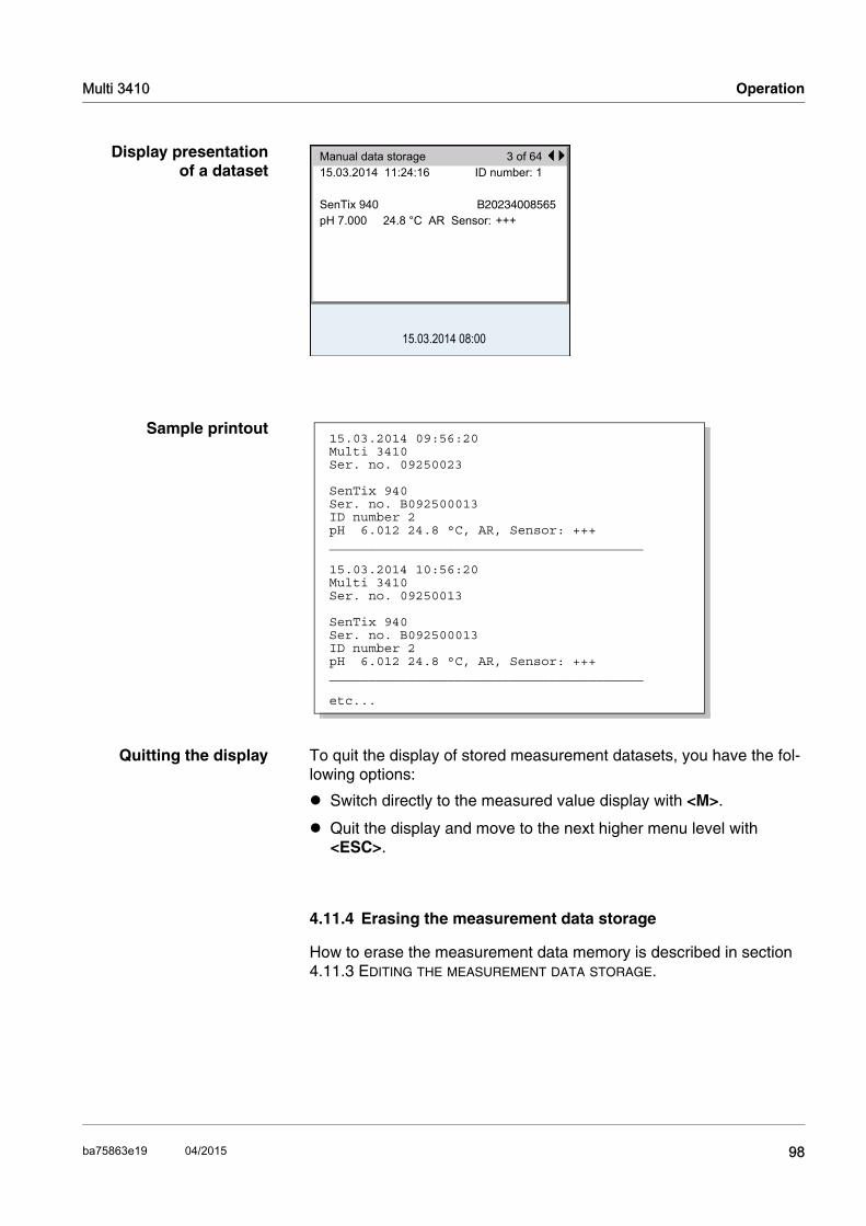
Multi 3410 Operation
Display presentationof a dataset
Sample printout
Quitting the display To quit the display of stored measurement datasets, you have the fol-lowing options:
Switch directly to the measured value display with <M>.
Quit the display and move to the next higher menu level with <ESC>.
4.11.4 Erasing the measurement data storage
How to erase the measurement data memory is described in section 4.11.3 EDITING THE MEASUREMENT DATA STORAGE.
Manual data storage 3 of 6415.03.2014 11:24:16 ID number: 1
SenTix 940 B20234008565pH 7.000 24.8 °C AR Sensor: +++
15.03.2014 08:00
15.03.2014 09:56:20Multi 3410 Ser. no. 09250023
SenTix 940Ser. no. B092500013ID number 2pH 6.012 24.8 °C, AR, Sensor: +++________________________________________
15.03.2014 10:56:20Multi 3410 Ser. no. 09250013
SenTix 940Ser. no. B092500013ID number 2pH 6.012 24.8 °C, AR, Sensor: +++________________________________________
etc...
98ba75863e19 04/2015
Operation Multi 3410
4.12 Transmitting data
4.12.1 USB interfaces
The meter has the following interfaces:
USB-B interface (USB Device)e.g. to connect a PC
USB-A interface (USB Host), e.g. to connect a USB flash drive or a
Via the USB-B interface (USB Device) you can transmit data to a PC or printer and update the meter software.
Via the USB-A interface (USB Host) it is possible to transfer data to an external USB memory device/USB printer.
4.12.2 Connecting the PC (USB-B interface (USB Device))
Connect the Multi 3410 to the PC via the USB-B interface.
Installation of the USBdriver on the PC
System requirements of the PC for installation of the USB driver:
PC with at least one free USB connection and CD-ROM drive
Windows 2000, Windows XP, Windows Vista or Windows 7.
1 Insert the supplied installation CD in the CD drive of your PC.
2 Install the driver from the CD.Follow the Windows installation instructions as necessary.
3 Connect the Multi 3410 to the PC via the USB-B interface.The meter is listed as a virtual COM interface among the con-nections in the Windows instrument manager.
4 Set the same transmission data at the connected instrument (PC): Baud rate: to be selected in the range 1200 ... 19200
Handshake: RTS/CTS
Set at the PC only:
– Parity: none
– Data bits: 8
– Stop bits: 1
99 ba75863e19 04/2015
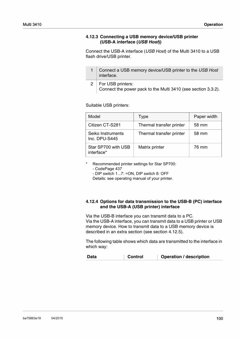
Multi 3410 Operation
4.12.3 Connecting a USB memory device/USB printer (USB-A interface (USB Host))
Connect the USB-A interface (USB Host) of the Multi 3410 to a USB flash drive/USB printer.
Suitable USB printers:
4.12.4 Options for data transmission to the USB-B (PC) interface and the USB-A (USB printer) interface
Via the USB-B interface you can transmit data to a PC. Via the USB-A interface, you can transmit data to a USB printer or USB memory device. How to transmit data to a USB memory device is described in an extra section (see section 4.12.5).
The following table shows which data are transmitted to the interface in which way:
1 Connect a USB memory device/USB printer to the USB Host interface.
2 For USB printers:Connect the power pack to the Multi 3410 (see section 3.3.2).
Model Type Paper width
Citizen CT-S281 Thermal transfer printer 58 mm
Seiko Instruments Inc. DPU-S445
Thermal transfer printer 58 mm
Star SP700 with USB interface*
* Recommended printer settings for Star SP700:- CodePage 437- DIP switch 1...7: =ON, DIP switch 8: OFFDetails: see operating manual of your printer.
Matrix printer 76 mm
Data Control Operation / description
100ba75863e19 04/2015
Operation Multi 3410
NoteThe following rule applies: With the exception of the menus, shortly pressing the <PRT> key generally outputs the display contents to the interface (displayed measured values, measuring datasets, calibration records). If there is a USB-B connection (such as to a PC) at the same time, the data are output only to the USB-B interface.
4.12.5 Data transmission to the USB-A interface (USB memory device)
Via the USB-A interface, you can transmit data to a USB memory or USB printer device. How to transmit data to a USB printer device is described in an extra section (see section 4.12.5).
The following table shows which data are transmitted to the interface in which way:
Currentmeasured values of all connected sensors
Manual With <PRT>
Simultaneously with every manual storage process (see section 4.11.1)
Automatic, at intervals
With <PRT_>. Then you can set the trans-mission interval
Simultaneously with every automatic storage process (see section 4.11.2)
Stored measured values
Manual Displayed dataset with <PRT> after calling up from the storage
All datasets with the Output to RS232/USB function (USB-B interface)
All datasets with the Output to USB flash drive or printer function (USB-A interface)
For details, see section 4.11.3.calibration records
Manual Displayed calibration record with <PRT>
All calibration records with <PRT_>
For details, see section 4.12.Automatic At the end of a calibration
procedure
101 ba75863e19 04/2015

Multi 3410 Operation
4.12.6 MultiLab Importer
With the aid of the MultiLab Importer software, you can record and eval-uate measurement data with a PC.
NoteMore detailed information can be found in the MultiLab Importer oper-ating manual.
4.13 MultiLab User
The user administration function is activated via the MultiLab User PC software.The MultiLab User PC software can be found on the enclosed CD-ROM.
NoteMore detailed information can be found in the MultiLab User operating manual.
4.14 Reset
You can reset (initialize) all sensor settings and sensor-independent settings separately from each other.
4.14.1 Resetting the measurement settings
NoteThe calibration data are reset to the default settings together with the measuring parameters. Recalibrate after performing a reset.
pH The following settings for pH measurements are reset to the default settings with the Reset function:
Data Control Operation / descriptionStored measured values
Manual All datasets with the Output to RS232/USB function.For details, see section 4.11.3.
Calibration data storage
Manual All stored calibration records of a sensor with the Output to USB flash drive or printer function.For details, see the menu for calibration and measurement settings of the sensor.
102ba75863e19 04/2015

Operation Multi 3410
The sensor settings are reset under the Reset menu item in the menu for calibration and measurement settings. To open the settings, display the required parameter in the measured value display and press the <MENU/ENTER> key.
ORP The following settings for ORP measurements are reset to the default settings with the Reset function:
The sensor settings are reset under the Reset menu item in the menu for calibration and measurement settings. To open the settings, display the required parameter in the measured value display and press the <MENU/ENTER> key.
Dissolved oxygen The following settings for D.O. measurements are reset to the default settings with the Reset function:
Setting Default settings
Buffer AutoCalTEC
Cal. interval 7 d
Unit for slope mV/pH
Measured parameter pH
pH resolution 0.001
mV resolution 0.1
Asymmetry 0 mV
Slope -59.2 mV
Man. temperature 25 °C
Single-point calibration off
Setting Default settings
mV resolution 0.1
Man. temperature 25 °C
Setting Default settings
Cal. interval 180d
Check interval 60 d
Measured parameter D.O. concentration
Relative slope (SRel) 1.00
Salinity (value) 0.0
103 ba75863e19 04/2015

Multi 3410 Operation
The sensor settings are reset under the Reset menu item in the menu for calibration and measurement settings. To open the settings, display the required parameter in the measured value display and press the <MENU/ENTER> key.
Conductivity The following settings for conductivity measurements are reset to the default settings with the Reset function:
The sensor settings are reset under the Reset menu item in the menu for calibration and measurement settings. To open the settings, display the required parameter in the measured value display and press the <MENU/ENTER> key.
Salinity (function) Off
Setting Default settings
Setting Default settings
Cal. interval 150 d
Measured parameter ϰ
Cell constant (c) Depending on the connected measuring cell:0.475 cm-1 (calibrated)0.475 cm-1 (set up)0.100 cm-1
Temperature compensation nLF
Reference temperature 25 °C
Temperature coefficient (TC) of the linear temperature compensation
2.000 %/K
TDS factor 1,00
104ba75863e19 04/2015

Operation Multi 3410
4.14.2 Resetting the system settings
The following system settings can be reset to the default condition:
The system settings are reset in the menu, Storage & config / System / Reset. To open the Storage & config menu, press the <MENU/ENTER_> key in the measured value display.
Setting Default settings
Language English
Acoustic signal on
Volume 6
Baud rate 4800 Baud
Output format ASCII
Decimal separator .
Brightness 15
Illumination Auto
Switchoff time 1 h
Temperature unit °C
USB Host on
Stability control on
105 ba75863e19 04/2015

Multi 3410 Operation
106ba75863e19 04/2015

Maintenance, cleaning, disposal Multi 3410
5 Maintenance, cleaning, disposal
5.1 Maintenance
The only maintenance activity required is replacing the batteries.
NoteSee the relevant operating manuals of the IDS sensors for instructions on maintenance.
5.1.1 Replacing the rechargeable batteries
CAUTIONMake sure that the poles of the rechargeable batteries are posi-tioned correctly.The ± signs on the batteries must correspond to the ± signs in the battery compartment.
NoteDispose of used batteries according to the local regulations of your
1 Unscrew the two screws (1) on the underside of the meter.
2 Open the battery compartment (2) on the underside of the meter.
3 Remove the four rechargeable batteries from the battery com-partment.
4 Place four new rechargeable batteries (type Mignon AA) in the battery compartment.
5 Close the battery compartment (2) and tighten the screws (1).
2
1
107 ba75863e19 04/2015

Multi 3410 Maintenance, cleaning, disposal
country.
End users within the European Union are obligated to return used bat-teries (even ecologically compatible ones) to a collection point set up for recycling purposes.
Batteries are marked with the crossed-out waste containersymbol. Therefore, they may not be disposed with the domestic waste.
5.2 Cleaning
Occasionally wipe the outside of the measuring instrument with a damp, lint-free cloth. Disinfect the housing with isopropanol as required.
CAUTIONThe housing is made of synthetic material (ABS). Thus, avoid con-tact with acetone or similar detergents that contain solvents. Re-move any splashes immediately.
5.3 Packing
This meter is sent out in a protective transport packing. We recommend: Keep the packing material. The original packing pro-tects the meter against damage during transport.
5.4 Disposal
NoteWithin the European Union, the batteries are removed at a specialized treatment center at the instrument's end of life. The instruments are taken to one of those specialized treatment centers via the recycling system set up for this purpose.
108ba75863e19 04/2015

What to do if... Multi 3410
6 What to do if...
6.1 General information
Sensor symbol flashes
Display
Meter does not react tokeystroke
You want to know whichsoftware version is in
the meter or IDS sensor
Cause Remedy
– Calibration interval expired – Recalibrate the measuring system
Cause Remedy
– Batteries almost empty – Charge the batteries (see section 3.3.2 CONNECTING THE POWER PACK / CHARGING THE BATTERIES)
– Replace the batteries (see section 5.1 MAINTENANCE)
Cause Remedy
– Operating condition undefined or EMC load unallowed
– Processor reset:Press the <ENTER> and <On/Off> key simultane-ously
Cause Remedy
– E. g., a question by the service department
– Switch on the meter.
– Open the menu, <ENTER_> / Storage & config / System / Service information. The instrument data are displayed.
or– Connect the sensor.
Press softkey [Info]/[More]. The sensor data are dis-played (see section 4.5)
109 ba75863e19 04/2015

Multi 3410 What to do if...
Data transmission toUSB memory device
does not work
Data transmission toUSB printer device does
not work
Error message,Only use rechargeable
batteries!Ni-MH 1.2 V, >2100 mAh
CAUTIONUnsuitable batterie types can cause damage during the charging process.
Cause Remedy
– Connected USB memory device has not been recognized, e. g.
– the USB memory device has been formattet to a file sys-tem which is not supported(e. g. NTFS)
– Use other USB memory device
– Reformat the USB memory device to FAT 16 or FAT 32 file system(Caution: Reformatting erases all data on the USB memory device. Back up all data before reformatting.)
Cause Remedy
– The USB-B interface is con-nected to a PC
– Disconnect the PC from the USB-B interface
– Connected USB memory device does not work
– Use a suitable USB printer device (see section 4.12.3)
– Check printer settings (see section 4.12.3)
– No power pack connected – Connect the power pack
Cause Remedy
– A voltage that is unusual for NiMH rechargeable batteries was found.
– Disconnect the power pack from the meter.
– Check whether there are suitable rechargeable batter-ies (Ni-MH 1.2 V, >2100 mAh) in the battery compart-ment.
– Unsuitable batteries:Insert suitable recharge-able batteries and recon-nect the power pack.
– Suitable batteries:Connect the power pack and close the error mes-sage with <[ESC]> or <M>.
110ba75863e19 04/2015

What to do if... Multi 3410
Error message, Memory error 1
Cause Remedy
– Instrument storage was not found
– Please contact the service.
111 ba75863e19 04/2015

Multi 3410 What to do if...
6.2 pH
Error message,OFL, UFL
Error message,Error
Cause Remedy
IDS pH sensor:
– Measured value outside the measuring range
– Use suitable IDS pH sensor
– Air bubble in front of the junction – Remove air bubble
– Air in the junction – Extract air or moisten junc-tion
– Gel electrolyte dried out – Exchange IDS pH sensor
Cause Remedy
IDS pH sensor:
– The values determined for zero point and slope of the IDS pH sensor are outside the allowed limits.
– Recalibrate
– Junction contaminated – Clean junction
– IDS pH sensor broken – Exchange IDS pH sensor
– Buffer solutions:
– The used buffer solutions are not suitable for the selected buffer set
– Select a different buffer set
or– Use different buffer solu-
tions
– Buffer solutions too old – Use only once.Note the shelf life
– Buffer solutions depleted – Change solutions
112ba75863e19 04/2015
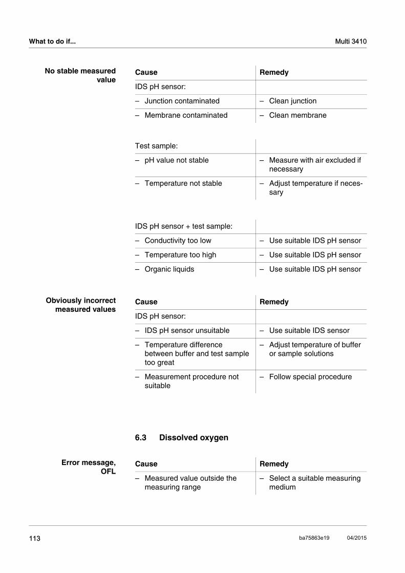
What to do if... Multi 3410
No stable measuredvalue
Obviously incorrectmeasured values
6.3 Dissolved oxygen
Error message,OFL
Cause Remedy
IDS pH sensor:
– Junction contaminated – Clean junction
– Membrane contaminated – Clean membrane
Test sample:
– pH value not stable – Measure with air excluded if necessary
– Temperature not stable – Adjust temperature if neces-sary
IDS pH sensor + test sample:
– Conductivity too low – Use suitable IDS pH sensor
– Temperature too high – Use suitable IDS pH sensor
– Organic liquids – Use suitable IDS pH sensor
Cause Remedy
IDS pH sensor:
– IDS pH sensor unsuitable – Use suitable IDS sensor
– Temperature difference between buffer and test sample too great
– Adjust temperature of buffer or sample solutions
– Measurement procedure not suitable
– Follow special procedure
Cause Remedy
– Measured value outside the measuring range
– Select a suitable measuring medium
113 ba75863e19 04/2015

Multi 3410 What to do if...
Error message,Error
6.4 Conductivity
Error message,OFL
Error message,Error
Cause Remedy
– Sensor contaminated – Clean the sensor
– Measured temperature outside the operating conditions (OFL/UFL displayed instead of temperature value)
– Observe the temperature range for the measuring medium
– Defective sensor – Replace sensor
NoteMore information, as well as notes on cleaning and replacement of sensors, are given in the documentation of your sensor.
Cause Remedy
– Measured value outside the measuring range
– Use suitable IDS conductiv-ity sensor
Cause Remedy
– Sensor contaminated – Clean sensor and replace it if necessary
– Calibration solution not suitable – Check calibration solutions
NoteMore information, as well as notes on cleaning and replacement of sensors, are given in the documentation of your sensor.
114ba75863e19 04/2015

What to do if... Multi 3410
6.5 Turbidity
Implausible turbidityvalues
Error message,OFL
Measured values too low
Measured values toohigh
Cause Remedy
– There are gas bubbles (e.g. air bubbles) in front of the measure-ment window
– Remove the gas bubbles, e.g. by immersing the sen-sor at an angle
– Incorrect calibration,e.g.:
– Unsuitable calibration stan-dard solutions (e.g. too old)
– Unsuitable calibration envi-ronment (e.g. gas bubbles, reflection, light)
– Check the calibration
– Minimum depth of immersion not observed
– Heed the minimum depth of immersion of the sensor (2 cm)
Cause Remedy
– Measured value outside the measuring range
– Select a suitable measuring medium
Cause Remedy
– Measurement window soiled – Clean the measurement window
Cause Remedy
– Reflection at the walls or bottom of the measuring vessel
– Keep the minimum distance of the sensor towards the walls and bottom of the measuring vessel (see sec-tion 6.5)
– Incidence of light – Use a light-proof measuring vessel
NoteMore information and instructions on cleaning and exchange of sen-sors are given in the documentation of your sensor.
115 ba75863e19 04/2015
Multi 3410 What to do if...
116ba75863e19 04/2015
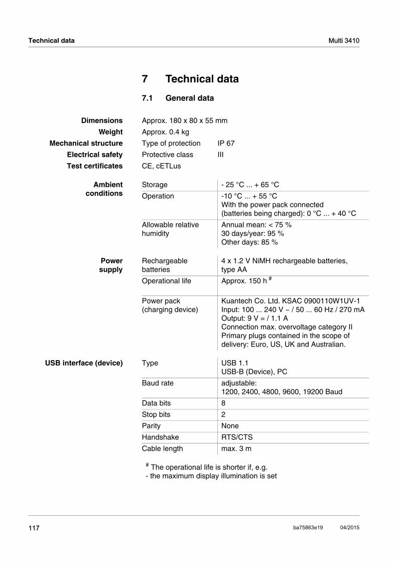
Technical data Multi 3410
1
7 Technical data
7.1 General data
Dimensions Approx. 180 x 80 x 55 mm
Weight Approx. 0.4 kg
Mechanical structure Type of protection IP 67
Electrical safety Protective class III
Test certificates CE, cETLus
Ambient conditions
Storage - 25 °C ... + 65 °C
Operation -10 °C ... + 55 °CWith the power pack connected (batteries being charged): 0 °C ... + 40 °C
Allowable relative humidity
Annual mean: < 75 %30 days/year: 95 %Other days: 85 %
Powersupply
Rechargeable batteries
4 x 1.2 V NiMH rechargeable batteries, type AA
Operational life Approx. 150 h #
Power pack (charging device)
Kuantech Co. Ltd. KSAC 0900110W1UV-1Input: 100 ... 240 V ~ / 50 ... 60 Hz / 270 mAOutput: 9 V = / 1.1 AConnection max. overvoltage category IIPrimary plugs contained in the scope of delivery: Euro, US, UK and Australian.
USB interface (device) Type USB 1.1USB-B (Device), PC
Baud rate adjustable: 1200, 2400, 4800, 9600, 19200 Baud
Data bits 8
Stop bits 2
Parity None
Handshake RTS/CTS
Cable length max. 3 m
# The operational life is shorter if, e.g. - the maximum display illumination is set
17 ba75863e19 04/2015

Multi 3410 Technical data
7.2 Measuring ranges, resolution, accuracy
NoteFurther data are given in the documentation of your sensor.
USB interface (host) Type USB 2.0USB-A (host), USB device
Applicable directivesand standards
EMC EC directive 2004/108/ECEN 61326-1EN 61000-3-2EN 61000-3-3FCC Class A
Meter safety EC directive 2006/95/ECEN 61010-1
IP protection class EN 60529
Measuring ranges,accuracy
Variable Measuring range Accuracy
Air pressure (absolute)*
300 ... 1100 mbar ± 4 mbar
* only available with connected D.O. sensor
FCC Class A Equipment Statement
Note: This equipment has been tested and found to comply with the limits for a Class A digital device, pursuant to Part 15 of the FCC Rules. These limits are designed to provide reasonable protection against harmful interference when the equipment is operated in a commercial environment. This equipment generates, uses, and can radiate radio frequency energy and, if not installed and used in accordance with the instruction manual, may cause harmful interference to radio communications. Operation of this equipment in a residential area is likely to cause harmful interference in which case the user will be required to correct the interference at his own expense.Changes or modifications not expressly approved by the manufacturer could void the user‘s authority to operate the equipment.
118ba75863e19 04/2015

Lists Multi 3410
8 Lists
This chapter provides additional information and orientation aids.
Specialist terms The glossary briefly explains the meaning of the specialist terms. How-ever, terms that should already be familiar to the target group are not described here.
Index The index will help you to find the topics that you are looking for.
Glossary
Adjusting To manipulate a measuring system so that the relevant value (e. g. the displayed value) differs as little as possible from the correct value or a value that is regarded as correct, or that the difference remains with-in the tolerance.
Asymmetry see zero point
AutoRange Name of the automatic selection of the measuring range.
Calibration Comparing the value from a measuring system (e. g. the displayed value) to the correct value or a value that is regarded as correct. Of-ten, this expression is also used when the measuring system is adjust-ed at the same time (see adjusting).
D.O. partial pressure Pressure caused by the oxygen in a gas mixture or liquid.
Electromotive force ofan electrode
The electromotive force U of the combination electrode is the measur-able electromotive force of an electrode in a solution. It equals the sum of all the galvanic voltages of the combination electrode. Its de-pendency on the pH results in the electrode function, which is charac-terized by the parameters, slope and zero point.
Junction The junction is a porous body in the housing wall of reference elec-trodes or electrolyte bridges. It arranges the electrical contact be-tween two solutions and makes the electrolyte exchange more difficult. The expression, junction, is also used for ground or junction-less transitions.
Measured parameter The measured parameter is the physical dimension determined by measuring, e. g. pH, conductivity or D.O. concentration.
Measured value The measured value is the special value of a measured parameter to be determined. It is given as a combination of the numerical value and unit (e. g. 3 m; 0.5 s; 5.2 A; 373.15 K).
ORP voltage The ORP is caused by oxidizing or reducing substances dissolved in water if these substances become effective on an electrode surface (e. g. a gold or platinum surface).
119 ba75863e19 04/2015

Multi 3410 Lists
Oxygen saturation Short name for "Relative D.O. saturation".
pH value The pH value is a measure of the acidic or basic effect of an aqueous solution. It corresponds to the negative decadic logarithm of the molal hydrogen ions activity divided by the unit of the molality. The practical pH value is the value of a pH measurement.
Potentiometry Name of a measuring technique. The signal (depending on the mea-sured parameter) of the electrode is the electrical potential. The elec-trical current remains constant.
Reset Restoring the original condition of all settings of a measuring system.
Resolution Smallest difference between two measured values that can be dis-played by a meter.
Salinity The absolute salinity SA of seawater corresponds to the relationship of the mass of dissolved salts to the mass of the solution (in g/kg). In practice, this dimension cannot be measured directly. Therefore, the practical salinity according to IOT is used for oceanographic monitoring. It is determined by measuring the electrical conductivity.
Salt content General designation for the quantity of salt dissolved in water.
Slope The slope of a linear calibration function.
Stability control(AutoRead )
Function to control the measured value stability.
Standard solution The standard solution is a solution where the measured value is known. It is used to calibrate a measuring system.
Test sample Designation of the test sample ready to be measured. Normally, a test sample is made by processing the original sample. The test sample and original sample are identical if the test sample was not processed.
Zero point The zero point of a pH combination electrode is the pH value at which the electromotive force of the pH combination electrode at a specified temperature is zero. Normally, this is at 25 °C.
120ba75863e19 04/2015

Multi 3410 Lists
Index
AAir calibration beaker . . . . . . . . . . . . . . . . . 68Authorized use . . . . . . . . . . . . . . . . . . . . . . 18Automatic switch-off . . . . . . . . . . . . . . . . . . 25AutoRead
Conductivity . . . . . . . . . . . . . . . . . . . . . 73O2 . . . . . . . . . . . . . . . . . . . . . . . . . . . . 65ORP . . . . . . . . . . . . . . . . . . . . . . . . . . . 61pH . . . . . . . . . . . . . . . . . . . . . . . . . . . . 38
BBattery compartment . . . . . . . . . . . . . . 21, 95
CCalibration
Conductivity . . . . . . . . . . . . . . . . . . . . . 79O2 . . . . . . . . . . . . . . . . . . . . . . . . . . . . 68pH . . . . . . . . . . . . . . . . . . . . . . . . . . . . 42
Calibration evaluationConductivity . . . . . . . . . . . . . . . . . . . . . 79O2 . . . . . . . . . . . . . . . . . . . . . . . . . . . . 68pH . . . . . . . . . . . . . . . . . . . . . . . . . . . . 46
Calibration intervalConductivity . . . . . . . . . . . . . . . . . . . . . 76O2 . . . . . . . . . . . . . . . . . . . . . . . . . . . . 67pH . . . . . . . . . . . . . . . . . . . . . . . . . . . . 47
Calibration pointspH . . . . . . . . . . . . . . . . . . . . . . . . . . . . 45
Calibration recordsConductivity . . . . . . . . . . . . . . . . . . . . . 81O2 . . . . . . . . . . . . . . . . . . . . . . . . . . . . 70pH . . . . . . . . . . . . . . . . . . . . . . . . . . . . 54
Cell constant . . . . . . . . . . . . . . . . . . . . . . . 79Connect the power pack . . . . . . . . . . . . . . 22Connecting a PC . . . . . . . . . . . . . . . . . 88, 90
DDataset . . . . . . . . . . . . . . . . . . . . . . . . . . . . 82Date and time . . . . . . . . . . . . . . . . . . . . . . . 31Default settings
Measured parameter . . . . . . . . . . . . . . 91System settings . . . . . . . . . . . . . . . . . . 94
Display . . . . . . . . . . . . . . . . . . . . . . . . . . . . 11
EEnergy saving feature . . . . . . . . . . . . . . . . 23
FFirmware update . . . . . . . . . . . . . . . . . . . 107
IInitial commissioning . . . . . . . . . . . . . . 21, 23Initialize . . . . . . . . . . . . . . . . . . . . . . . . . . . 91Interval for calibration . . . . . . . . . . . . . . . . 47
KKeys . . . . . . . . . . . . . . . . . . . . . . . . . . . . . . 10
MMeasured value display . . . . . . . . . . . . . . . 27Measurement accuracy . . . . . . . . . . . . . . . 47Measurement data storage
Edit . . . . . . . . . . . . . . . . . . . . . . . . . . . . 86Erase . . . . . . . . . . . . . . . . . . . . . . . . . . 86Storage locations . . . . . . . . . . . . . . . . . 82
Measurement dataset . . . . . . . . . . . . . . . . 82Measuring
Conductivity . . . . . . . . . . . . . . . . . . . . . 72O2 . . . . . . . . . . . . . . . . . . . . . . . . . . . . 64ORP voltage . . . . . . . . . . . . . . . . . . . . 60pH . . . . . . . . . . . . . . . . . . . . . . . . . . . . 38
Menu for calibration and measurement settingsConductivity . . . . . . . . . . . . . . . . . . . . . 76O2 . . . . . . . . . . . . . . . . . . . . . . . . . . . . 67pH/ORP . . . . . . . . . . . . . . . . . . . . . 40, 62
Menus (navigation) . . . . . . . . . . . . . . . . . . 27Messages . . . . . . . . . . . . . . . . . . . . . . . . . 28
OOperational safety . . . . . . . . . . . . . . . . . . . 18
PpH buffer sets . . . . . . . . . . . . . . . . . . . . . . 42Precautions . . . . . . . . . . . . . . . . . . . . . . . . 17
RReset . . . . . . . . . . . . . . . . . . . . . . . . . . . . . 91RS232 interface . . . . . . . . . . . . . . . . . . . . . 90
SSafety . . . . . . . . . . . . . . . . . . . . . . . . . . . . . 17Scope of delivery . . . . . . . . . . . . . . . . . . . . 21
121ba75863e19 04/2015
Lists Multi 3410
Setting the date . . . . . . . . . . . . . . . . . . . . . 23Setting the time . . . . . . . . . . . . . . . . . . . . . 23Single-point calibration
pH . . . . . . . . . . . . . . . . . . . . . . 49, 52, 53Slope
pH . . . . . . . . . . . . . . . . . . . . . . . . . . . . 42Slope, relative . . . . . . . . . . . . . . . . . . . . . . 68Socket field . . . . . . . . . . . . . . . . . . . . . . . . 13Stability control
automatic . . . . . . . . . . . . . . . . . . . . . . . 35Conductivity . . . . . . . . . . . . . . . . . . . . . 73O2 . . . . . . . . . . . . . . . . . . . . . . . . . . . . 65ORP . . . . . . . . . . . . . . . . . . . . . . . . . . 61pH . . . . . . . . . . . . . . . . . . . . . . . . . . . . 38
Storage interval . . . . . . . . . . . . . . . . . . . . . 83Storing in memory . . . . . . . . . . . . . . . . . . . 63
Automatic . . . . . . . . . . . . . . . . . . . . . . 83Manual . . . . . . . . . . . . . . . . . . . . . . . . 83
TTemperature compensation . . . . . . . . . . . 75Temperature measurement
Conductivity . . . . . . . . . . . . . . . . . . . . . 71O2 . . . . . . . . . . . . . . . . . . . . . . . . . . . . 63pH . . . . . . . . . . . . . . . . . . . . . . . . . . . . 37
Three-point calibrationpH . . . . . . . . . . . . . . . . . . . . . . . . . . . . 50
Transmitting data . . . . . . . . . . . . . . . . . . . 88Transmitting measured values . . . . . . . . . 88Two-point calibration
pH . . . . . . . . . . . . . . . . . . . . . . 49, 52, 54
ZZero point of pH combination electrode . . 42
122 ba75863e19 04/2015

Appendix: Firmware update Multi 3410
9 Appendix: Firmware update
With the Multi 3410 you can update the firmware of your meter and IDS sensors.
9.1 Firmware update for the meter Multi 3410
General information Available firmware updates for the meter are provided on the Internet. With the "Firmware Update " program and a PC you can update the firmware of the Multi 3410 to the newest version.
For the update you have to connect the meter to a PC.
For the update via the USB-B interface, the following is required:
a free USB interface (virtual COM port) on the PC
the driver for the USB interface (on the enclosed CD-ROM)
the USB cable (included in the scope of delivery of the Multi 3410).
Program installation
Program start
Firmware update
After switching the meter off and on you can check whether the meter has taken over the new software version (see page 109).
1 Install the downloaded firmware update on a PC.
An update folder is created in the Windows start menu. If an update folder already exists for the meter (or meter type), the new data are displayed there.
2 In the windows start menu, open the update folder and start the firmware update program for the meter
3 Using the USB interface cable, connect the Multi 3410 to a USB interface (virtual COM port) of the PC.
4 Switch on the Multi 3410.
5 In the firmware update program, start the update process with OK.
6 Follow the instructions of the firmware update program.During the programming process, a corresponding message and a progress bar (in %) are displayed. The programming process takes up to 15 minutes. A termina-tory message is displayed after a successful programming pro-cess. The firmware update is completed.
7 Disconnect the Multi 3410 from the PC. The Multi 3410 is ready for operation again.
123 ba75863e19 04/2015

Multi 3410 Appendix: Firmware update
9.2 Firmware-Update for IDS Sensors
General information Available firmware updates for IDS sensors are provided on the Inter-net. With the "Firmware Update" program and a PC you can update the firmware of an IDS sensor to the newest version.
For updating, connect the IDS sensor to the Multi 3410, and the Multi 3410 to a PC.
For the update via the USB-B interface, the following is required:
a free USB interface (virtual COM port) on the PC
the driver for the USB interface (on the enclosed CD-ROM)
the USB cable (included in the scope of delivery of the Multi 3410).
Program installation
Program start
Firmware update
After switching the meter off and on you can check whether the sensor has taken over the new software version (see page 109).
1 Install the downloaded firmware update on a PC.
An update folder is created in the Windows start menu. If an update folder already exists for the sensor (or sensor type), the new data are displayed there.
2 In the windows start menu, open the update folder and start the firmware update program for the IDS sensor
3 Connect the IDS sensor to the Multi 3410 meter.
4 Using the USB interface cable, connect the Multi 3410 to a USB interface (virtual COM port) of the PC.
5 Switch on the Multi 3410.
6 In the firmware update program, start the update process with OK.
7 Follow the instructions of the firmware update program.During the programming process, a corresponding message and a progress bar (in %) are displayed. The programming process takes up to 5 minutes. A terminatory message is displayed after a successful programming process. The firmware update is completed.
8 Disconnect the Multi 3410 from the PC. Meter and sensor are ready for operation again.
124ba75863e19 04/2015


Wissenschaftlich-TechnischeWerkstätten GmbH
Dr.-Karl-Slevogt-Straße 1D-82362 WeilheimGermany
+49 881 183-0+49 881 [email protected]
Tel:Fax:E-Mail:Internet:
1) The tissue in plants that brings water upward from the roots;2) a leading global water technology company.
We're 12,500 people unified in a common purpose: creating innovative solutionsto meet our world's water needs. Developing new technologies that will improvethe way water is used, conserved, and re-used in the future is central to our work.We move, treat, analyze, and return water to the environment, and we help peopleuse water efficiently, in their homes, buildings, factories and farms. In more than150 countries, we have strong, long-standing relationships with customers whoknow us for our powerful combination of leading product brands and applicationsexpertise, backed by a legacy of innovation.
For more information on how Xylem can help you, go to www.xyleminc.com
Xylem | m|ˈ əzīl


