MCS Total Solution for all your Control Needs Energy Efficient and RoHS Compliant 5580 Enterprise Pkwy. Fort Myers, FL 33905 Office: 239-694-0089 Fax: 239-694-0031 www.mcscontrols.com MCS-CONNECT Manual and Installation Guide Version 1.4 Written in Sun Micro Systems Java Local communication @ 19200 baud Local Ethernet @ 10/100/1000 MBPS Revision 2015-09-29
Transcript
MCS TotalSolutionfor all yourControlNeeds
Energy Efficient and RoHS Compliant
5580 Enterprise Pkwy.Fort Myers, FL 33905
Office: 239-694-0089Fax: 239-694-0031
www.mcscontrols.com
MCS-CONNECTManual and Installation Guide
Version 1.4
Written in Sun Micro Systems Java
Local communication @ 19200 baud
Local Ethernet @ 10/100/1000 MBPS
Revision 2015-09-29
MCS-CONNECT REVISION 1.4
2
The MCS Commitment is to provide practical solutions for the industries needs and to be both a leader and partner in the effective use of
microprocessor controls.
Micro Control Systems, Inc.5580 Enterprise ParkwayFort Myers, Florida 33905
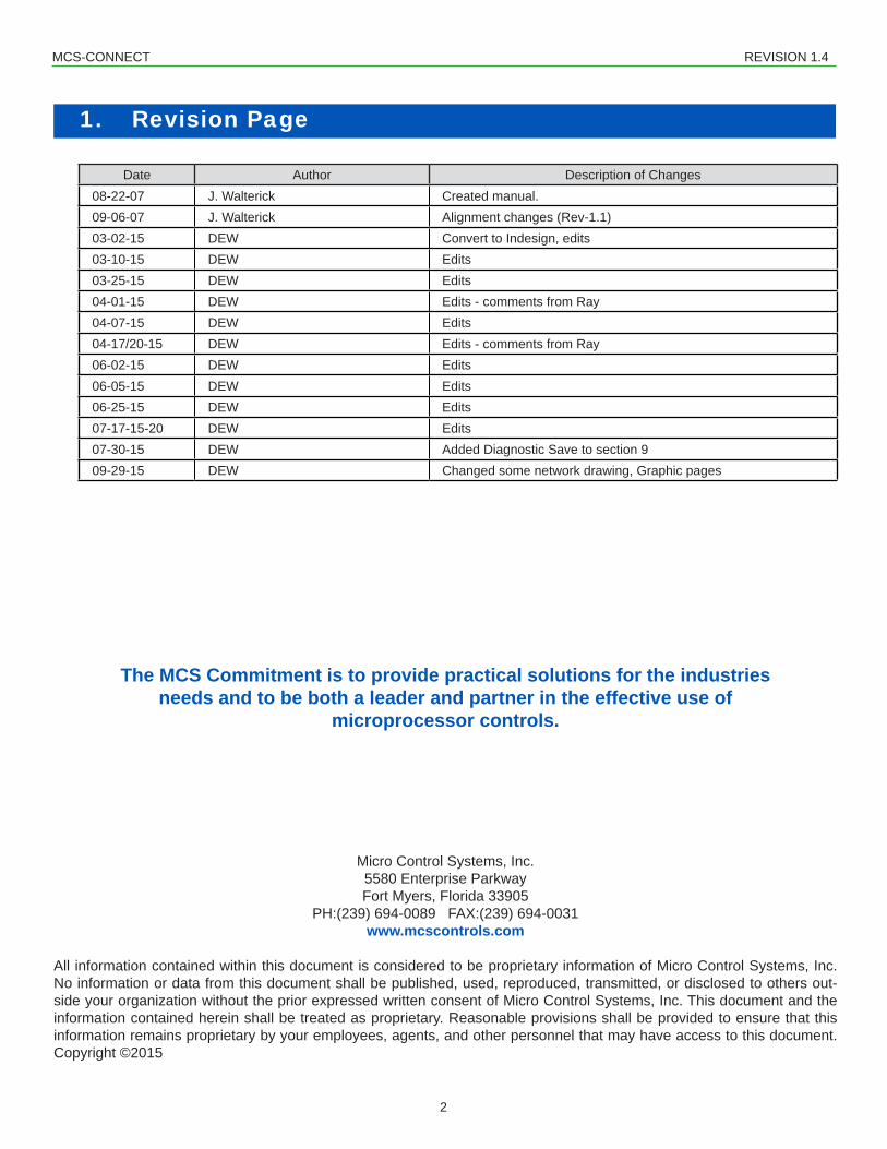
Date Author Description of Changes08-22-07 J. Walterick Created manual.09-06-07 J. Walterick Alignment changes (Rev-1.1)03-02-15 DEW Convert to Indesign, edits03-10-15 DEW Edits03-25-15 DEW Edits04-01-15 DEW Edits - comments from Ray04-07-15 DEW Edits04-17/20-15 DEW Edits - comments from Ray06-02-15 DEW Edits06-05-15 DEW Edits06-25-15 DEW Edits07-17-15-20 DEW Edits07-30-15 DEW Added Diagnostic Save to section 909-29-15 DEW Changed some network drawing, Graphic pages
MCS-CONNECT REVISION 1.4
3
2. Table of Contents1. Revision Page ......................................................................................................................................................22. Table of Contents .................................................................................................................................................33. Introduction ..........................................................................................................................................................5
3.1. About MCS Controllers ....................................................................................................................................54. MCS-CONNECT PC Requirements & Product Features ...................................................................................65. Setting up Communication with Controllers .....................................................................................................7
5.1. REMOTE - DIALUP - USING MCS-MODEM, MCS-485 GATEWAY ..............................................................75.2. LOCAL CONNECTION USING CROSSOVER ETHERNET CABLE ..............................................................85.3. NETWORK RS-485 CONNECTION ................................................................................................................9
6. Installing MCS-CONNECT .................................................................................................................................106.1. Downloading from our Website......................................................................................................................106.2. Installing.........................................................................................................................................................11
7. Setup Options for MCS-CONNECT ...................................................................................................................127.1. MCS-PC-CONNECT Communication Setup .................................................................................................127.2. PC Communication Speed & Wait Timersonds .............................................................................................137.3. PC Communication Modem - Remote ...........................................................................................................137.4. Initialization Dial String ..................................................................................................................................14
7.4.1 Local Communication Errors ...............................................................................................................147.5. Remote Communications ..............................................................................................................................157.6. DIALUP - .......................................................................................................................................................15
7.6.1.1. Remote Communication Errors ...............................................................................................157.6.1.2. IP (Internet) - ..........................................................................................................................167.6.1.3. IP LANTRONIX - ....................................................................................................................16
7.7. General Setup Options ..................................................................................................................................177.8. Tables Options...............................................................................................................................................18
7.8.1 Alarm Table - choose to show ‘ONLY LOCKOUT ALARMS’ or ...........................................................18‘SHOW ALLALARMS’ ..........................................................................................................................18
7.8.2 Table Font Size - Only affects Magnum V14 and MicroMag SW versions. ........................................18Default “Small’......................................................................................................................................18
7.9. Network Options - Make any changes, click save. ........................................................................................207.10. Extended History Option - Make any changes, click save.............................................................................207.11. Create Scheduled Print..................................................................................................................................217.12. Alarm Alerts ...................................................................................................................................................22
7.12.1 Setup for Alarm Alerts Menu................................................................................................................227.12.2 Alarm Alert Types.................................................................................................................................23
8. System Information Screen ..............................................................................................................................249. Accessing the Function Screens when connected to Controller ..................................................................25
9.1. Getting Authorized ........................................................................................................................................25At any time while connected to a MCS controller the user can get authorized to a higher level by clicking on the ‘View Only’ button located at the top of the screen.Higher levels of Authorization may be necessary to make changes to the controller you are connected to. .....................................................................................................259.2. Exiting MCS-CONNECT ............................................................................................................................269.3. To Rescan the Network for MCS Controllers ..............................................................................................269.4. Accessing the Graph Screen .....................................................................................................................269.5. Accessing the Transmit Function (NOTE: The ‘RUN/STOP’ should be put ..................................................... in stop before transmitting a new CFG file). ..................................................................................................269.6. Accessing the Receive Function ...................................................................................................................279.7. Understanding the Authorization Screen ......................................................................................................279.8. Diagnostic Save.............................................................................................................................................279.9. Accessing the Print Function ........................................................................................................................279.10. Edit Time/Date Screen ................................................................................................................................28
MCS-CONNECT REVISION 1.4
4
9.11. Graphics Screen ............................................................................................................................................2810. Menu Bar Descriptions ......................................................................................................................................29
10.1. FILE BAR - Allows user to exit MCS-CONNECT...........................................................................................2910.2. SETUP BAR - Toggle lockout alarms ............................................................................................................2910.3. LOAD A GRAPH FILE BAR - Click here to load a ‘Graph’ file. The system will pull back data when connect-ed to a controller for viewing. This can be done offline. You do not need to be connected to the MAGNUM. ........2910.4. RESET/CLEAR BAR - The following screen will appear when the RESET button is selected. ....................3010.5. WORKSPACE BAR .......................................................................................................................................31
10.5.1 CREATING A NEW WORKSPACE......................................................................................................3110.5.2 Switch Workspace - User can select different ‘SAVED WORKSPACES’ ...........................................3210.5.3 Save Current Workspace - Choose the items you wish to view and save the current workspace. ...3210.5.4 Update Workspace - If you make changes to your saved workspace, click to ‘Update’ the workspace.........3210.5.5 Delete Single Workspace - click to delete a single workspace............................................................3210.5.6 Delete All Other Workspaces - deletes all workspaces except the current workspace .......................3210.5.7 Center all Internal Frames- Click here and each open frame will be centered in your viewing area. ..3210.5.8 Resolution Based Quad Frames - Click here and four frames will center within your viewing area....32
10.6. VIEW BAR - ..................................................................................................................................................3210.7. BUTTON BAR - Click to hide/show ..................................................................................................................
Button Bar, short cuts to ‘Scan’, ‘Graph’,‘Transmit’, ......................................................................................3210.8. HELP BAR - ..................................................................................................................................................32
11. Accessing the Various Screens when connected to a Controller ................................................................3311.1. Relay Output Information...............................................................................................................................34
11.1.1 Relay Output Manual Status Change ..................................................................................................3511.1.2 Relay Output Manual Percentage Value Change ................................................................................3611.1.3 Relay Output Manual Resetting Run Hours\Cycles Today ..................................................................37
11.2. Sensor Input Information ...............................................................................................................................3811.2.1 Sensor Input Manual Status Change...................................................................................................3911.2.2 Sensor Input Filter/Offset Change .......................................................................................................4011.2.3 Sensor Input Sensor Type Change......................................................................................................4011.2.4 Clearing of a ‘Last On/ MAX TDY’ and ‘Last Off/ MIN TDY’ cell ..........................................................40
11.3. Analog Output Information.............................................................................................................................4111.4. Status Information..........................................................................................................................................42
11.4.1 Capacity Information............................................................................................................................4311.4.2 Compressor Information ......................................................................................................................4311.4.3 Compressor/Superheat Info.................................................................................................................4411.4.4 EXV Info...............................................................................................................................................44
11.5. Alarm Information ..........................................................................................................................................4511.6. Set Point Information .....................................................................................................................................46
11.6.1 Set Point Value Change.......................................................................................................................4711.6.2 Set Point Time Change........................................................................................................................47
12. Standard Schedule Window for MCS Controller .............................................................................................4813. Service Windows ...............................................................................................................................................4914. Graph Capabilities Screen of MCS Controllers ...............................................................................................50
14.1. Setup for the Graph Screen...........................................................................................................................5215. MCS-GRAPHICS .................................................................................................................................................5416. Troubleshooting Information ............................................................................................................................56
MCS-CONNECT REVISION 1.4
5
3. Introduction
MCS-CONNECT software is part of the MCS Support System. Its purpose is to provide both local and remote communication for MCS micro controllers either by themselves or as part of a network.MCS-CONNECT supports the following controllers:
MCS-CONNECT permits the user to monitor the status of the micro controller in real time and, with proper authorization, changes can be made to the system. In as fast as 10 seconds configurationfilescanbetransmittedtoorreceivedfromaMCSmicrocontroller.Another powerful feature of MCS-CONNECT is its ability to graph event history. Since MCS controllers automatically perform history logging, the user can select which inputs or outputs to graph and view the results either in real time or over a user selectable period of time. MCS-CONNECTsupportstheSAVEofhistorydataintheGRAPHfunctionasa*.txtfile.ThisallowstheusertobringthedataupinMCS-CONNECTofflineorinaspreadsheetprogramsuch as Microsoft Excel.Updates for MCS-CONNECT can be downloaded directly from the MCS website under “Support”, PC Software.The program is available as Microsoft Windows based software or as Linux based software.This manual was created using Adobe Indesign. An approved OEM of MCS may obtain a copy of this manual in PDF format and make copies or change sections of this manual to develop custom documentation for a site where an MCS controller is installed. In this way, MCS supports the documentation requirements of individual customer sites.
3.1. About MCS ControllersThe MCS controllers are rugged microprocessor based controllers that are designed for the hostile environment of the HVAC/R industry. They are designed to provide primary control, no mechanical controls; interface with building management systems; communicate both locally and remotely. TheMCScontrollersprovideflexibilitywithsetpointsandcontroloptionsthatcanbeselectedpriorto commissioning a system or when the unit is live and functioning. Displays, alarms and other interfaces are accomplished in a clear and simple language that informs the user as to the status of the controller.
The MCS controllers are designed to safeguard the system that is being controlled, eliminate the need for manual intervention and to provide a simple but meaningful man-machine-interface.
Additional information on the setup and using MCS-CONNECT can be found on our web site.A Powerpoint presentation can be found at:
http://www.mcscontrols.com/Support/Presentation
MCS-CONNECT REVISION 1.4
6
4. MCS-CONNECT PC Requirements & Product FeaturesTo install and run the program we suggest the following minimum system requirements:
• PC with a Pentium2-class or higher processor• Windows 7 or later operating system or Linux operating system• Minimum 1GB of RAM• Minimum 4GB Drive• 14.4k baud modem or higher for remote communications• 1280 x 800 pixel or higher display• Ethernet 10/100/1000• USB port 2.0 or higher
MCS-CONNECT PRODUCT FEATURES• Java application runs on Windows/Linux• Local communication @ 19200 baud• Local Ethernet @ 10/100 MBPS• Remote communication via phone or Internet• Email/Test Message alarm alerts• AutoPrinttofileonalarms• Daily Scheduled Print to Files• Temperature and PSI Conversion Wizard• Extended History File Save• Interactive P/T Chart• Lookup Tables• Hide / Show Applicable Data• Diagnostic Save/Auto-Send• Window/Grids auto sizing based on screen resolution• Customizable Workspace saving allow easy recall of window position & sizing• Algorithm control states display• Static & dynamic graphing / trending data• Alarm retrieval & handling - these items can be printed and saved to PC for analysis and backup• Manual / Auto mode control• Setpointmodification• Schedulemodification• Multiple authorization levels for security• Runtime / Cycle count information• Transmit/Receiveconfigurationinasfastas10seconds• Sensor Diagnostics• Graphic Interface Sub List
1. Customized to application2. User Customizable Gauges3. State Based Color and Image changes4. Animated device—pump rotating, comp moving, fan spin, etc.5. Easy view and access via graphic interface
MCS-CONNECT REVISION 1.4
7
4.10. Types Of Network Setups5. Setting up Communication with ControllersThe MCS 485 Network can support up to 20 MCS controllers. Access to the network can be local or remote via a 14.4K Baud modem. The PC connected to the network should be running at least Windows 7 or higher with MCS-CONNECT V17 or higher.
Each MCS controller in the network must be assigned a unique software network address. With proper authorization, this can be setup using a MCS controller and LCD/Keypad. This address will be the key in establishing communications with the appropriate MCS controller. This address can be changed from the LCD / keypad. (It is suggested that network addresses start with 1. This will allow any unit that has not had the address changed since leaving the factory to be accessible at address 0, which is the default.)
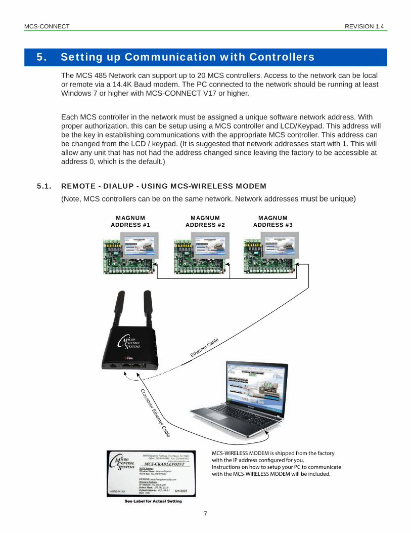
5.1. REMOTE - DIALUP - USING MCS-WIRELESS MODEM (Note, MCS controllers can be on the same network. Network addresses must be unique)
MAGNUMADDRESS #1
MAGNUMADDRESS #2
MAGNUMADDRESS #3
MCS-WIRELESS MODEM is shipped from the factorywith the IP address con�gured for you. Instructions on how to setup your PC to communicatewith the MCS-WIRELESS MODEM will be included.
Ethernet Cable
Crossover Ethernet Cable
MCS-CONNECT REVISION 1.4
8
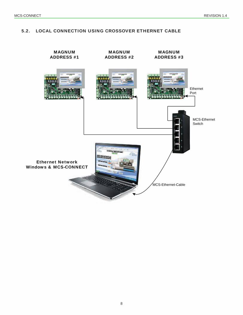
5.2. LOCAL CONNECTION USING CROSSOVER ETHERNET CABLE
MAGNUMADDRESS #1
MAGNUMADDRESS #2
MAGNUMADDRESS #3
Ethernet NetworkWindows & MCS-CONNECT
etworkS-CONNECT
MCS-Ethernet Switch
Ethernet Port
MCS-Ethernet-Cable
MCS-CONNECT REVISION 1.4
9
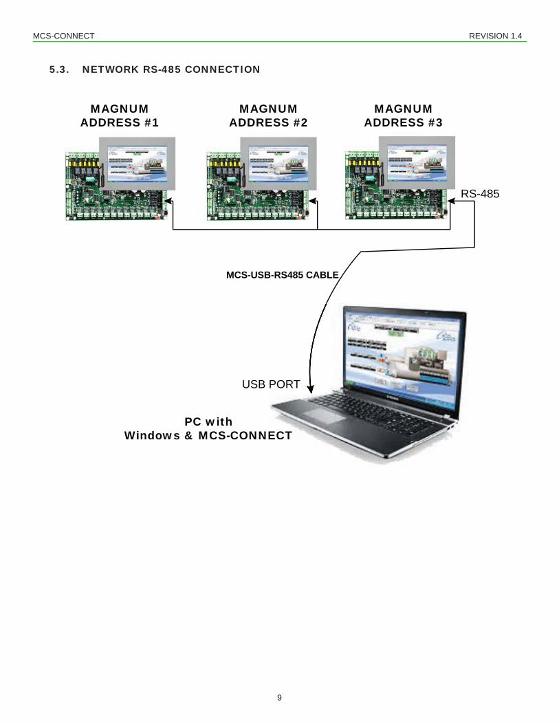
5.3. NETWORK RS-485 CONNECTION
MAGNUMADDRESS #1
MAGNUMADDRESS #2
MAGNUMADDRESS #3
PC withWindows & MCS-CONNECT
MCS-USB-RS485 CABLE
NNECT
RS-485
USB PORT
MCS-CONNECT REVISION 1.4
10
6. Installing MCS-CONNECT6.1. Downloading from our Website
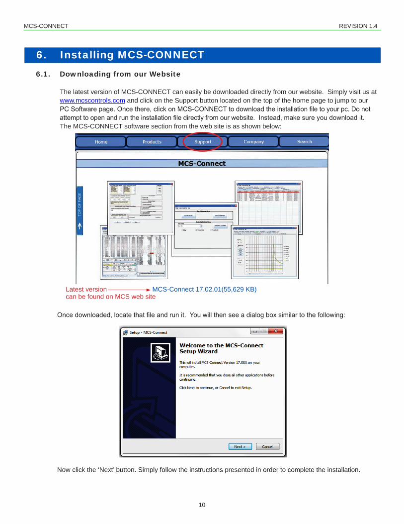
The latest version of MCS-CONNECT can easily be downloaded directly from our website. Simply visit us at www.mcscontrols.com and click on the Support button located on the top of the home page to jump to our PCSoftwarepage.Oncethere,clickonMCS-CONNECTtodownloadtheinstallationfiletoyourpc.Donotattempttoopenandruntheinstallationfiledirectlyfromourwebsite.Instead,makesureyoudownloadit.The MCS-CONNECT software section from the web site is as shown below:
Now click the ‘Next’ button. Simply follow the instructions presented in order to complete the installation.
Latest version MCS-Connect 17.02.01(55,629 KB)can be found on MCS web site
MCS-CONNECT REVISION 1.4
11
6.2. Installing
Once installed, MCS-CONNECT is ready to be executed. The PC must be connected to an MCS controller or a MCS network by one of the following:
• Locally with a MCS-USB-RS485 cable connected from a USB port on the PC to the RS-485 port on the MCS controllers.
• MCS-485-GATEWAY with MCS-USB-RS-232 cable to USB port on PC• Ethernet port using crossover cable connection • Remotely with a PC that has a 14.4-baud modem and a phone line that is available to the PC.
NOTE: TO MAKE FIRMWARE CHANGES TO A CONTROLLER FROM MCS-CONNECT, YOU MUST BE LOCALLY COMMUNICATING WITH THE CONTROLLER.
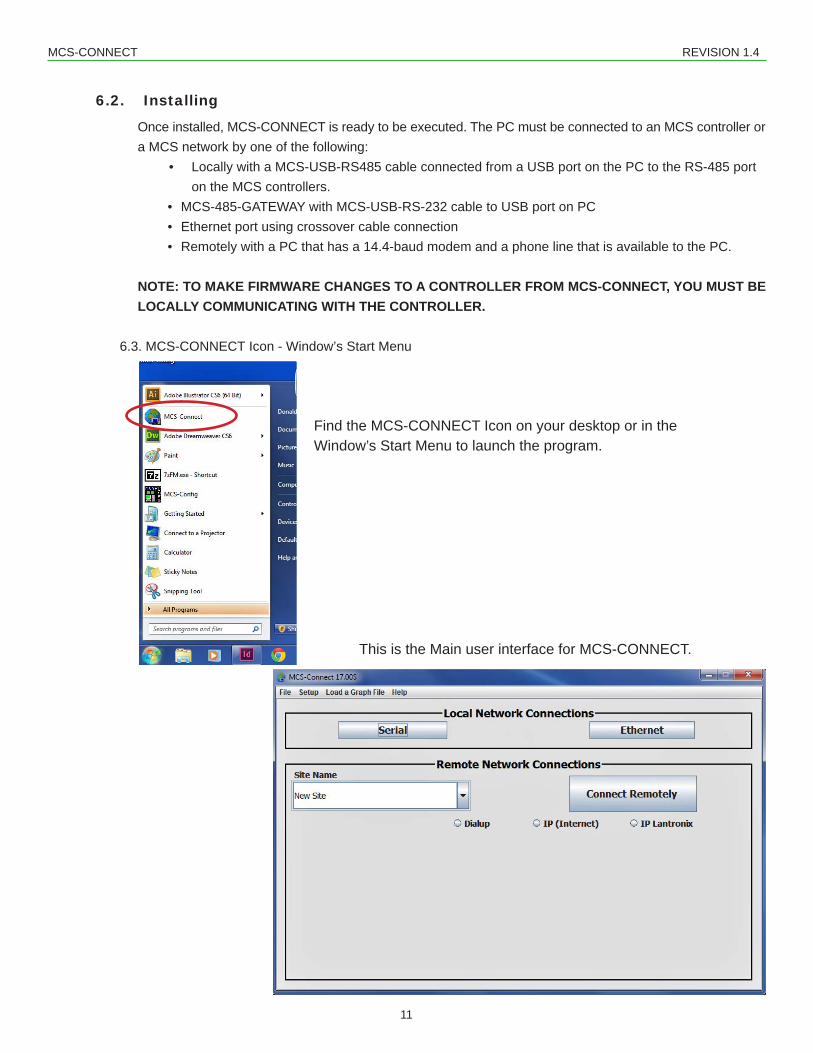
6.3. MCS-CONNECT Icon - Window’s Start Menu
Find the MCS-CONNECT Icon on your desktop or in the Window’s Start Menu to launch the program.
This is the Main user interface for MCS-CONNECT.
MCS-CONNECT REVISION 1.4
12
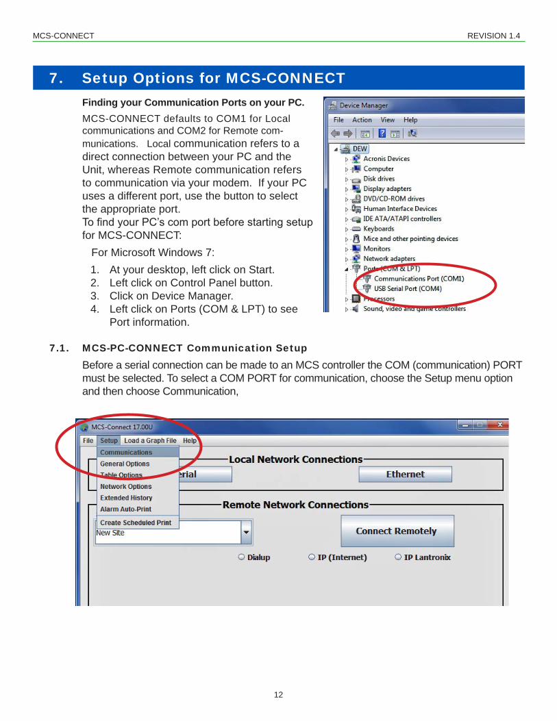
7. Setup Options for MCS-CONNECTFinding your Communication Ports on your PC.MCS-CONNECT defaults to COM1 for Local communications and COM2 for Remote com-munications. Local communication refers to a direct connection between your PC and the Unit, whereas Remote communication refers to communication via your modem. If your PC uses a different port, use the button to select the appropriate port. TofindyourPC’scomportbeforestartingsetupfor MCS-CONNECT: For Microsoft Windows 7:
1. At your desktop, left click on Start.2. Left click on Control Panel button.3. Click on Device Manager.4. Left click on Ports (COM & LPT) to see Port information.
7.1. MCS-PC-CONNECT Communication Setup
Before a serial connection can be made to an MCS controller the COM (communication) PORT must be selected. To select a COM PORT for communication, choose the Setup menu option and then choose Communication,
MCS-CONNECT REVISION 1.4
13
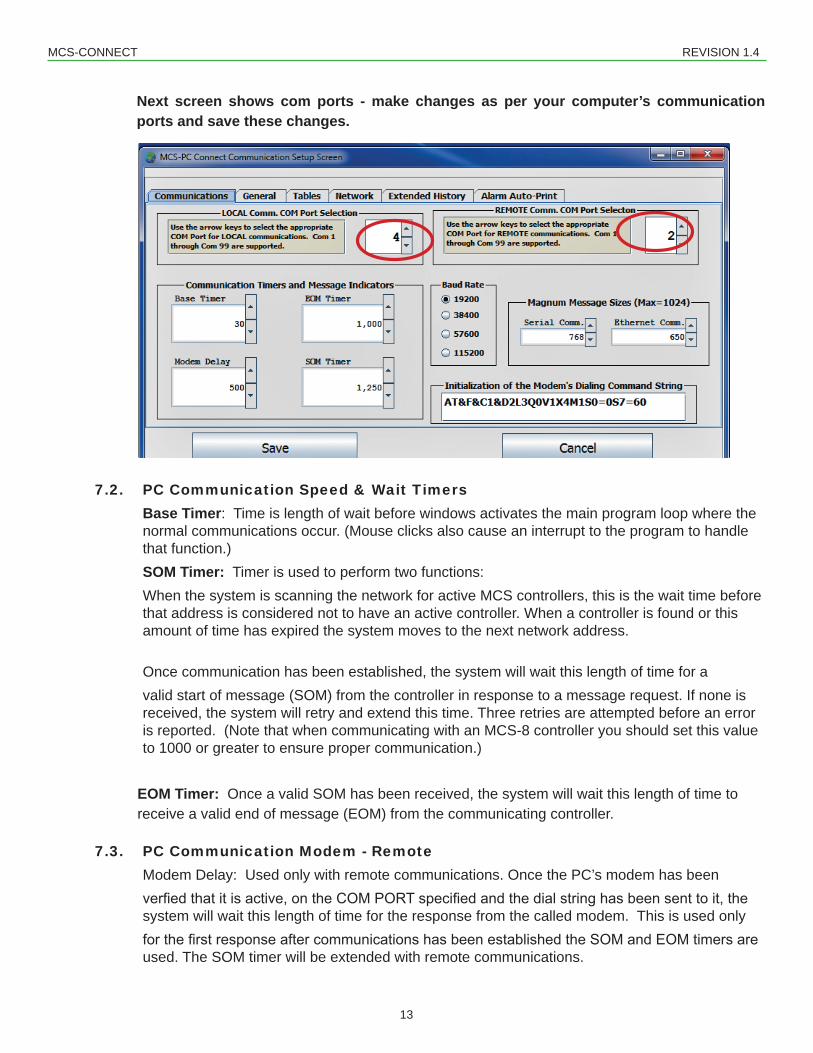
Next screen shows com ports - make changes as per your computer’s communication ports and save these changes.
7.2. PC Communication Speed & Wait TimersondsBase Timer: Time is length of wait before windows activates the main program loop where the normal communications occur. (Mouse clicks also cause an interrupt to the program to handle that function.)SOM Timer: Timer is used to perform two functions:When the system is scanning the network for active MCS controllers, this is the wait time before that address is considered not to have an active controller. When a controller is found or this amount of time has expired the system moves to the next network address.
Once communication has been established, the system will wait this length of time for a valid start of message (SOM) from the controller in response to a message request. If none is received, the system will retry and extend this time. Three retries are attempted before an error is reported. (Note that when communicating with an MCS-8 controller you should set this value to 1000 or greater to ensure proper communication.)
EOM Timer: Once a valid SOM has been received, the system will wait this length of time to receive a valid end of message (EOM) from the communicating controller.
7.3. PC Communication Modem - RemoteModem Delay: Used only with remote communications. Once the PC’s modem has been verfiedthatitisactive,ontheCOMPORTspecifiedandthedialstringhasbeensenttoit,thesystem will wait this length of time for the response from the called modem. This is used only forthefirstresponseaftercommunicationshasbeenestablishedtheSOMandEOMtimersareused. The SOM timer will be extended with remote communications.
MCS-CONNECT REVISION 1.4
14
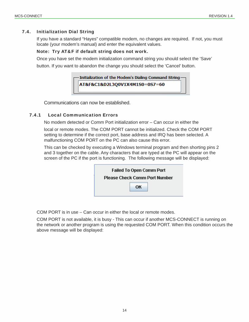
7.4. Initialization Dial StringIf you have a standard “Hayes” compatible modem, no changes are required. If not, you must locate (your modem’s manual) and enter the equivalent values.Note: Try AT&F if default string does not work.Once you have set the modem initialization command string you should select the ‘Save’ button. If you want to abandon the change you should select the ‘Cancel’ button.
Communications can now be established.
7.4.1 Local Communication ErrorsNo modem detected or Comm Port initialization error – Can occur in either the local or remote modes. The COM PORT cannot be initialized. Check the COM PORT setting to determine if the correct port, base address and IRQ has been selected. A malfunctioning COM PORT on the PC can also cause this error. This can be checked by executing a Windows terminal program and then shorting pins 2 and 3 together on the cable. Any characters that are typed at the PC will appear on the screen of the PC if the port is functioning. The following message will be displayed:
COM PORT is in use – Can occur in either the local or remote modes. COM PORT is not available, it is busy - This can occur if another MCS-CONNECT is running on the network or another program is using the requested COM PORT. When this condition occurs the above message will be displayed:
MCS-CONNECT REVISION 1.4
15
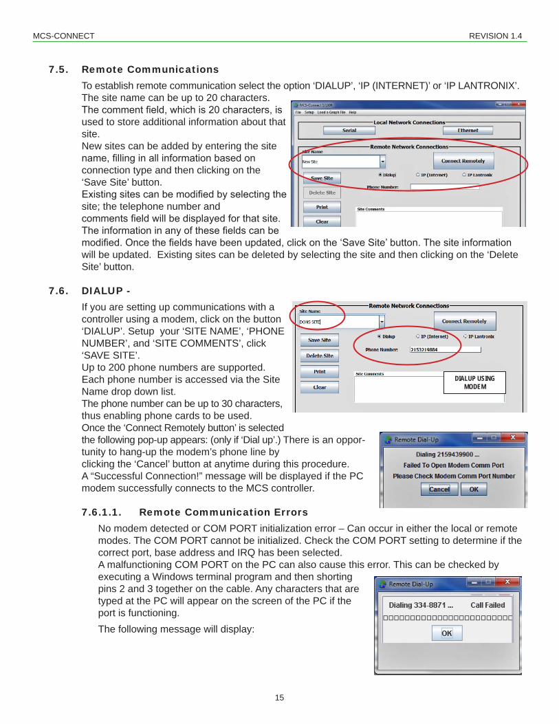
7.5. Remote CommunicationsTo establish remote communication select the option ‘DIALUP’, ‘IP (INTERNET)’ or ‘IP LANTRONIX’.The site name can be up to 20 characters. Thecommentfield,whichis20characters,isused to store additional information about that site. New sites can be added by entering the site name,fillinginallinformationbasedonconnection type and then clicking on the ‘Save Site’ button. Existingsitescanbemodifiedbyselectingthesite; the telephone number and commentsfieldwillbedisplayedforthatsite.Theinformationinanyofthesefieldscanbemodified.Oncethefieldshavebeenupdated,clickonthe‘SaveSite’button.Thesiteinformationwill be updated. Existing sites can be deleted by selecting the site and then clicking on the ‘Delete Site’ button.
7.6. DIALUP - If you are setting up communications with a controller using a modem, click on the button ‘DIALUP’. Setup your ‘SITE NAME’, ‘PHONE NUMBER’, and ‘SITE COMMENTS’, click ‘SAVE SITE’.Up to 200 phone numbers are supported. Each phone number is accessed via the Site Name drop down list. The phone number can be up to 30 characters, thus enabling phone cards to be used.Once the ‘Connect Remotely button’ is selected the following pop-up appears: (only if ‘Dial up’.) There is an oppor-tunity to hang-up the modem’s phone line by clicking the ‘Cancel’ button at anytime during this procedure. A “Successful Connection!” message will be displayed if the PC modem successfully connects to the MCS controller.
7.6.1.1. Remote Communication ErrorsNo modem detected or COM PORT initialization error – Can occur in either the local or remote modes. The COM PORT cannot be initialized. Check the COM PORT setting to determine if the correct port, base address and IRQ has been selected. A malfunctioning COM PORT on the PC can also cause this error. This can be checked by executing a Windows terminal program and then shorting pins 2 and 3 together on the cable. Any characters that are typed at the PC will appear on the screen of the PC if the port is functioning. The following message will display:
DIALUP USING MODEM
MCS-CONNECT REVISION 1.4
16
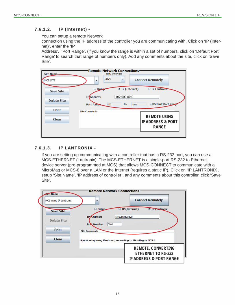
7.6.1.2. IP (Internet) - You can setup a remote Network connection using the IP address of the controller you are communicating with. Click on ‘IP (Inter-net)’, enter the ‘IP Address’, ‘Port Range’, (if you know the range is within a set of numbers, click on ‘Default Port Range’ to search that range of numbers only). Add any comments about the site, click on ‘Save Site’.
7.6.1.3. IP LANTRONIX - If you are setting up communicating with a controller that has a RS-232 port, you can use a MCS-ETHERNET (Lantronix) .The MCS-ETHERNET is a single-port RS-232 to Ethernet device server (pre-programmed at MCS) that allows MCS-CONNECT to communicate with a MicroMag or MCS-8 over a LAN or the Internet (requires a static IP). Click on ‘IP LANTRONIX , setup ‘Site Name’, ‘IP address of controller’, and any comments about this controller, click ‘Save Site’.
REMOTE USING IP ADDRESS & PORT
RANGE
REMOTE, CONVERTING ETHERNET TO RS-232
IP ADDRESS & PORT RANGE
MCS-CONNECT REVISION 1.4
17
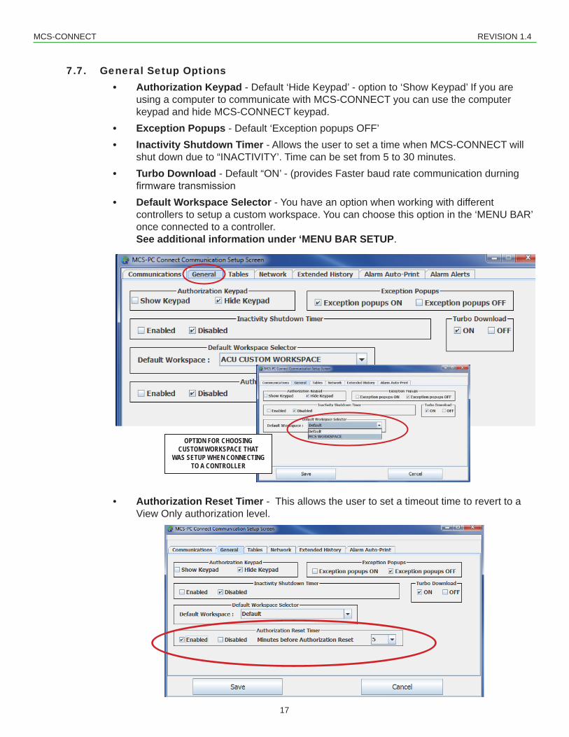
7.7. General Setup Options • Authorization Keypad - Default ‘Hide Keypad’ - option to ‘Show Keypad’ If you are using a computer to communicate with MCS-CONNECT you can use the computer keypad and hide MCS-CONNECT keypad. • Exception Popups - Default ‘Exception popups OFF’ • Inactivity Shutdown Timer - Allows the user to set a time when MCS-CONNECT will
shut down due to “INACTIVITY’. Time can be set from 5 to 30 minutes. • Turbo Download - Default “ON’ - (provides Faster baud rate communication durning
firmwaretransmission • Default Workspace Selector - You have an option when working with different controllers to setup a custom workspace. You can choose this option in the ‘MENU BAR’
once connected to a controller. See additional information under ‘MENU BAR SETUP.
• Authorization Reset Timer - This allows the user to set a timeout time to revert to a View Only authorization level.
OPTION FOR CHOOSING CUSTOM WORKSPACE THAT
WAS SETUP WHEN CONNECTING TO A CONTROLLER
MCS-CONNECT REVISION 1.4
18
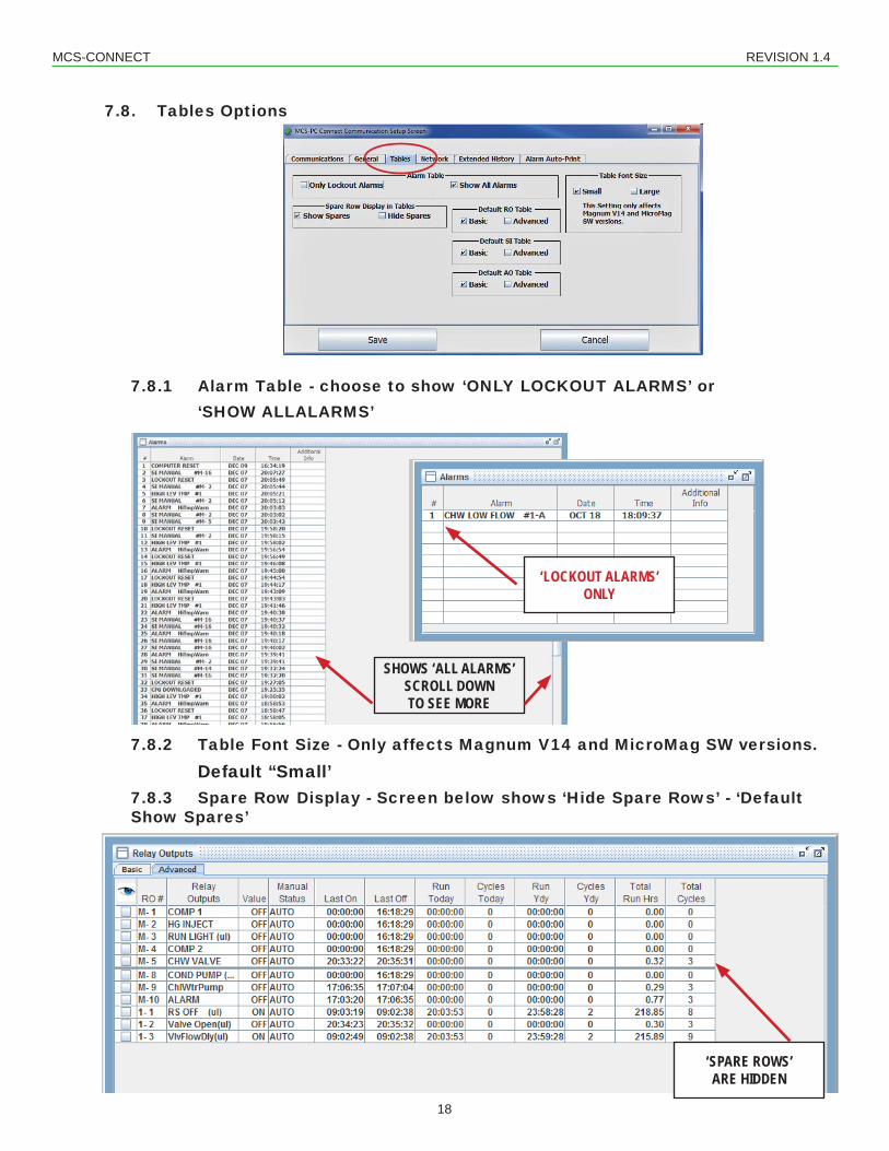
7.8. Tables Options
7.8.1 Alarm Table - choose to show ‘ONLY LOCKOUT ALARMS’ or ‘SHOW ALLALARMS’
7.8.2 Table Font Size - Only affects Magnum V14 and MicroMag SW versions. Default “Small’
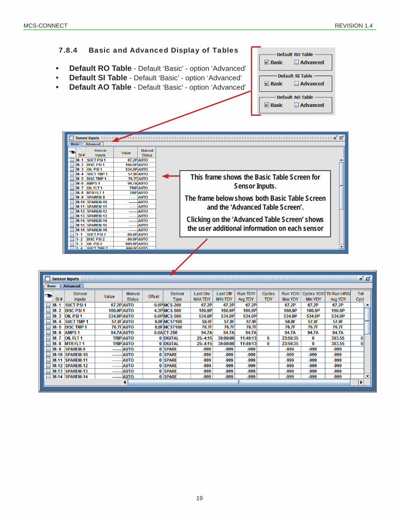
This frame shows the Basic Table Screen for Sensor Inputs.
The frame below shows both Basic Table Screen and the ‘Advanced Table Screen’.
Clicking on the ‘Advanced Table Screen’ shows the user additional information on each sensor
MCS-CONNECT REVISION 1.4
20
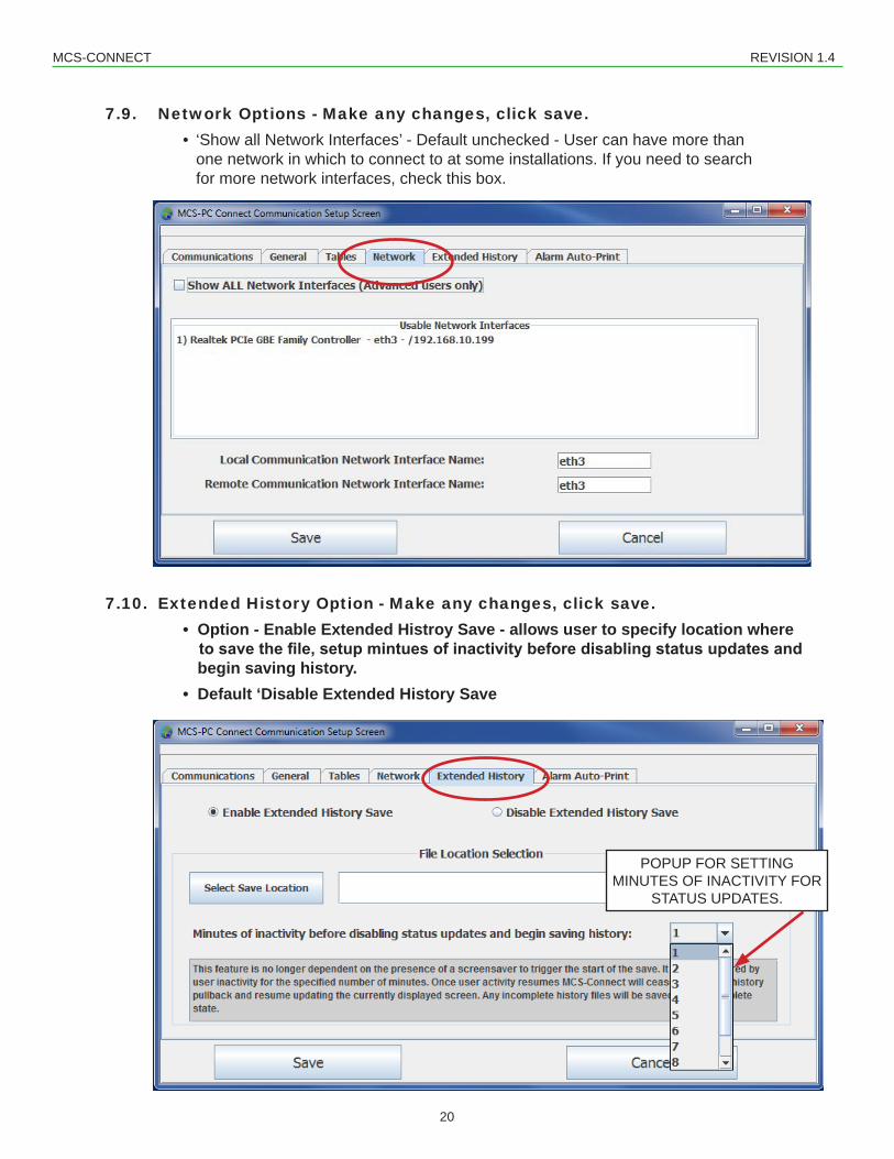
7.9. Network Options - Make any changes, click save. • ‘Show all Network Interfaces’ - Default unchecked - User can have more than
one network in which to connect to at some installations. If you need to search for more network interfaces, check this box.
7.10. Extended History Option - Make any changes, click save. • Option - Enable Extended Histroy Save - allows user to specify location where
to save the file, setup mintues of inactivity before disabling status updates and begin saving history. • Default ‘Disable Extended History Save
POPUP FOR SETTING MINUTES OF INACTIVITY FOR
STATUS UPDATES.
MCS-CONNECT REVISION 1.4
21
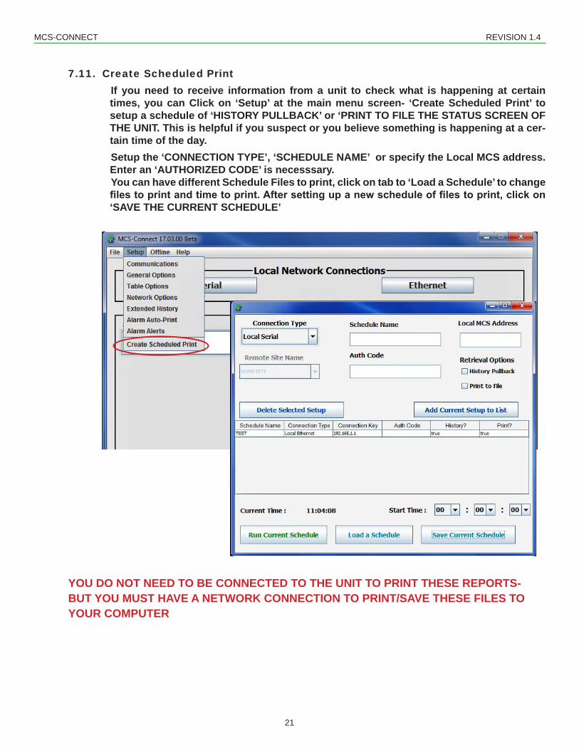
7.11. Create Scheduled PrintIf you need to receive information from a unit to check what is happening at certain times, you can Click on ‘Setup’ at the main menu screen- ‘Create Scheduled Print’ to setup a schedule of ‘HISTORY PULLBACK’ or ‘PRINT TO FILE THE STATUS SCREEN OF THE UNIT. This is helpful if you suspect or you believe something is happening at a cer-tain time of the day.Setup the ‘CONNECTION TYPE’, ‘SCHEDULE NAME’ or specify the Local MCS address. Enter an ‘AUTHORIZED CODE’ is necesssary.You can have different Schedule Files to print, click on tab to ‘Load a Schedule’ to change files to print and time to print. After setting up a new schedule of files to print, click on ‘SAVE THE CURRENT SCHEDULE’
YOU DO NOT NEED TO BE CONNECTED TO THE UNIT TO PRINT THESE REPORTS- BUT YOU MUST HAVE A NETWORK CONNECTION TO PRINT/SAVE THESE FILES TO YOUR COMPUTER
MCS-CONNECT REVISION 1.4
22
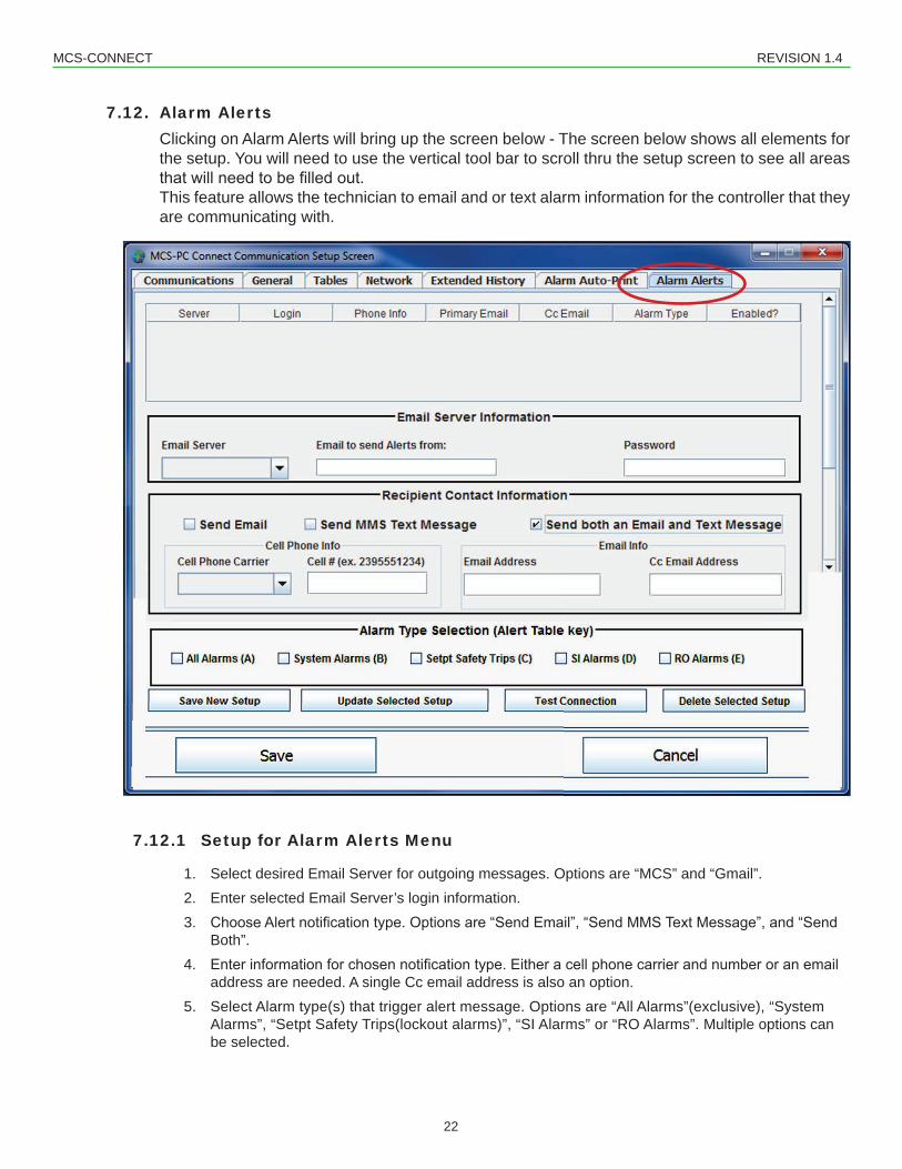
7.12. Alarm AlertsClicking on Alarm Alerts will bring up the screen below - The screen below shows all elements for the setup. You will need to use the vertical tool bar to scroll thru the setup screen to see all areas thatwillneedtobefilledout.This feature allows the technician to email and or text alarm information for the controller that they are communicating with.
7.12.1 Setup for Alarm Alerts Menu
1. Select desired Email Server for outgoing messages. Options are “MCS” and “Gmail”.2. Enter selected Email Server’s login information.3. ChooseAlertnotificationtype.Optionsare“SendEmail”,“SendMMSTextMessage”,and“Send
address are needed. A single Cc email address is also an option.5. Select Alarm type(s) that trigger alert message. Options are “All Alarms”(exclusive), “System
Alarms”, “Setpt Safety Trips(lockout alarms)”, “SI Alarms” or “RO Alarms”. Multiple options can be selected.
MCS-CONNECT REVISION 1.4
23
6. Click the “Save New Setup” button at the bottom of scrollable panel.7. OncefullyfilledinyoumaytesttheSetup’sfunctionalitybyclickingthe“TestConnection”button.
Apopupmessagewillverifythatthemessagewassent.Youcanthencheckthespecifiedac-count for the test message.
8. Once the new setup is added to the Alarm Alert Table at the top of the scrollable panel it can be activated by checking the “Enabled?” check box in the last column of the Alarm Alert Table.
9. A saved Alarm Alert Setup can be updated with new information by clicking on the row in the Alarm Alert Table that you would like to edit. This will load the setup into the Alarm info setup whereitcanbeedited.Whenfinishededitingclickthe“UpdateSelectedSetup”button.
10. Whenfinishedcreatingand/orupdatingAlarmAlertsclickthe“Save”buttonoftheSetupUserInterface. This will close the Setup UI and save the created Alarm Alerts. Your enabled Alarm Alerts will be active once you are connected to the desired Controller and in the Status Screen.
7.12.2 Alarm Alert Types
SYSTEM ALARMSHVAC SETPOINT SAFETIESREF SETPOINT SAFETIES
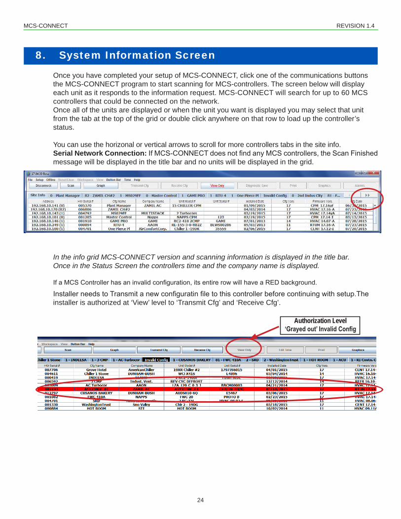
Once you have completed your setup of MCS-CONNECT, click one of the communications buttons the MCS-CONNECT program to start scanning for MCS-controllers. The screen below will display each unit as it responds to the information request. MCS-CONNECT will search for up to 60 MCS controllers that could be connected on the network.Once all of the units are displayed or when the unit you want is displayed you may select that unit from the tab at the top of the grid or double click anywhere on that row to load up the controller’s status.
You can use the horizonal or vertical arrows to scroll for more controllers tabs in the site info.Serial Network Connection: IfMCS-CONNECTdoesnotfindanyMCScontrollers,theScanFinishedmessage will be displayed in the title bar and no units will be displayed in the grid.
In the info grid MCS-CONNECT version and scanning information is displayed in the title bar. Once in the Status Screen the controllers time and the company name is displayed.
InstallerneedstoTransmitanewconfiguratinfiletothiscontrollerbeforecontinuingwithsetup.Theinstaller is authorized at ‘View’ level to ‘Transmit Cfg’ and ‘Receive Cfg’.
Authorization Level‘Grayed out’ Invalid Config
8. System Information Screen
MCS-CONNECT REVISION 1.4
25
9. Accessing the Function Screens when connected to Controller
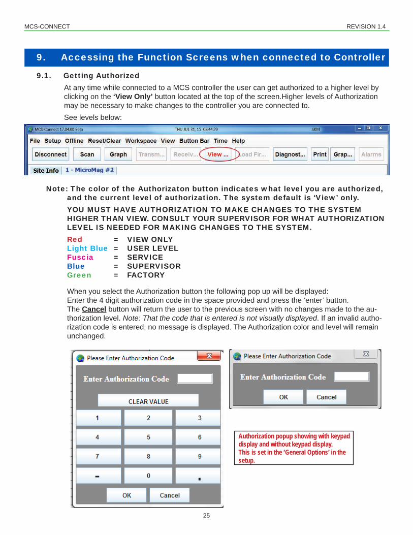
9.1. Getting AuthorizedAt any time while connected to a MCS controller the user can get authorized to a higher level by clicking on the ‘View Only’ button located at the top of the screen.Higher levels of Authorization may be necessary to make changes to the controller you are connected to.
See levels below:
Note: The color of the Authorizaton button indicates what level you are authorized, and the current level of authorization. The system default is ‘View’ only.
YOU MUST HAVE AUTHORIZATION TO MAKE CHANGES TO THE SYSTEM HIGHER THAN VIEW. CONSULT YOUR SUPERVISOR FOR WHAT AUTHORIZATION
LEVEL IS NEEDED FOR MAKING CHANGES TO THE SYSTEM. Red = VIEW ONLY Light Blue = USER LEVEL Fuscia = SERVICE Blue = SUPERVISOR Green = FACTORY
When you select the Authorization button the following pop up will be displayed: Enter the 4 digit authorization code in the space provided and press the ‘enter’ button. The Cancel button will return the user to the previous screen with no changes made to the au-
thorization level. Note: That the code that is entered is not visually displayed. If an invalid autho-rization code is entered, no message is displayed. The Authorization color and level will remain unchanged.
Authorization popup showing with keypad display and without keypad display.This is set in the ‘General Options’ in the setup.
MCS-CONNECT REVISION 1.4
26
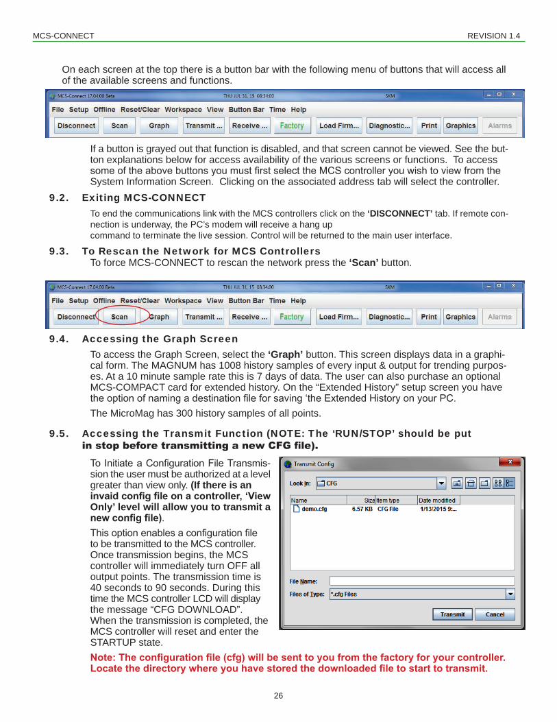
On each screen at the top there is a button bar with the following menu of buttons that will access all of the available screens and functions.
If a button is grayed out that function is disabled, and that screen cannot be viewed. See the but-ton explanations below for access availability of the various screens or functions. To access someoftheabovebuttonsyoumustfirstselecttheMCScontrolleryouwishtoviewfromtheSystem Information Screen. Clicking on the associated address tab will select the controller.
9.2. Exiting MCS-CONNECT To end the communications link with the MCS controllers click on the ‘DISCONNECT’ tab. If remote con-
nection is underway, the PC’s modem will receive a hang up command to terminate the live session. Control will be returned to the main user interface.
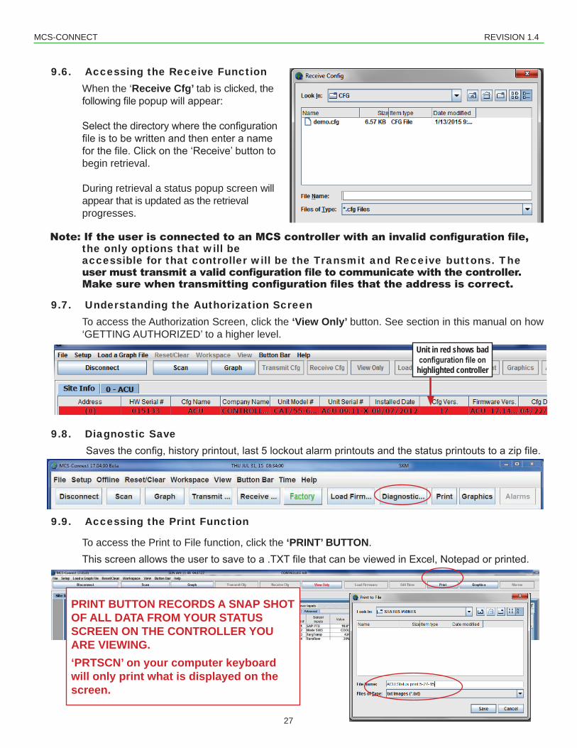
9.3. To Rescan the Network for MCS Controllers To force MCS-CONNECT to rescan the network press the ‘Scan’ button.
9.4. Accessing the Graph Screen To access the Graph Screen, select the ‘Graph’ button. This screen displays data in a graphi-
cal form. The MAGNUM has 1008 history samples of every input & output for trending purpos-es. At a 10 minute sample rate this is 7 days of data. The user can also purchase an optional
MCS-COMPACT card for extended history. On the “Extended History” setup screen you have theoptionofnamingadestinationfileforsaving‘theExtendedHistoryonyourPC.
The MicroMag has 300 history samples of all points.
9.5. Accessing the Transmit Function (NOTE: The ‘RUN/STOP’ should be put instopbeforetransmittinganewCFGfile).
ToInitiateaConfigurationFileTransmis-sion the user must be authorized at a level greater than view only. (If there is an
invaid config file on a controller, ‘View Only’ level will allow you to transmit a new config file).Thisoptionenablesaconfigurationfileto be transmitted to the MCS controller. Once transmission begins, the MCS controller will immediately turn OFF all output points. The transmission time is 40 seconds to 90 seconds. During this time the MCS controller LCD will display the message “CFG DOWNLOAD”. When the transmission is completed, the MCS controller will reset and enter the STARTUP state. Note: The configuration file (cfg) will be sent to you from the factory for your controller. Locate the directory where you have stored the downloaded file to start to transmit.
MCS-CONNECT REVISION 1.4
27
9.6. Accessing the Receive Function When the ‘Receive Cfg’ tab is clicked, the
During retrieval a status popup screen will appear that is updated as the retrieval
progresses.
Note:IftheuserisconnectedtoanMCScontrollerwithaninvalidconfigurationfile,the only options that will be accessible for that controller will be the Transmit and Receive buttons. The usermusttransmitavalidconfigurationfiletocommunicatewiththecontroller.Makesurewhentransmittingconfigurationfilesthattheaddressiscorrect.
9.7. Understanding the Authorization Screen To access the Authorization Screen, click the ‘View Only’ button. See section in this manual on how ‘GETTING AUTHORIZED’ to a higher level.
To access the Print to File function, click the ‘PRINT’ BUTTON. Thisscreenallowstheusertosavetoa.TXTfilethatcanbeviewedinExcel,Notepadorprinted.
Unit in red shows bad configuration file on
highlighted controller
PRINT BUTTON RECORDS A SNAP SHOT OF ALL DATA FROM YOUR STATUS SCREEN ON THE CONTROLLER YOU ARE VIEWING.‘PRTSCN’ on your computer keyboard will only print what is displayed on the screen.
MCS-CONNECT REVISION 1.4
28
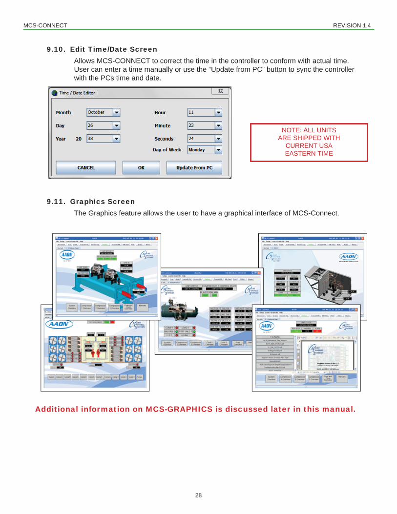
9.10. Edit Time/Date Screen Allows MCS-CONNECT to correct the time in the controller to conform with actual time. User can enter a time manually or use the “Update from PC” button to sync the controller with the PCs time and date.
9.11. Graphics Screen The Graphics feature allows the user to have a graphical interface of MCS-Connect.
Additional information on MCS-GRAPHICS is discussed later in this manual.
NOTE: ALL UNITS ARE SHIPPED WITH
CURRENT USA EASTERN TIME
MCS-CONNECT REVISION 1.4
29
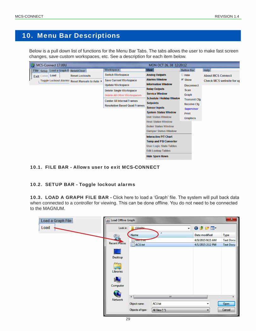
Below is a pull down list of functions for the Menu Bar Tabs. The tabs allows the user to make fast screen changes, save custom workspaces, etc. See a description for each item below.
10. Menu Bar Descriptions
10.1. FILE BAR - Allows user to exit MCS-CONNECT
10.2. SETUP BAR - Toggle lockout alarms
10.3. LOAD A GRAPH FILE BAR - Clickheretoloada‘Graph’file.Thesystemwillpullbackdatawhen connected to a controller for viewing.Thiscanbedoneoffline.Youdonotneedtobeconnectedto the MAGNUM.
MCS-CONNECT REVISION 1.4
30
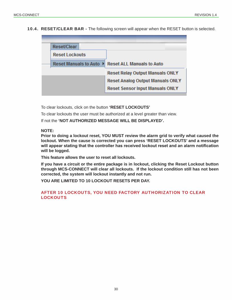
10.4. RESET/CLEAR BAR - The following screen will appear when the RESET button is selected.
To clear lockouts, click on the button ‘RESET LOCKOUTS’ To clear lockouts the user must be authorized at a level greater than view. If not the ‘NOT AUTHORIZED MESSAGE WILL BE DISPLAYED’.
NOTE:Prior to doing a lockout reset, YOU MUST review the alarm grid to verify what caused the lockout. When the cause is corrected you can press ‘RESET LOCKOUTS’ and a message will appear stating that the controller has received lockout reset and an alarm notification will be logged. This feature allows the user to reset all lockouts. If you have a circuit or the entire package is in lockout, clicking the Reset Lockout button through MCS-CONNECT will clear all lockouts. If the lockout condition still has not been corrected, the system will lockout instantly and not run.YOU ARE LIMITED TO 10 LOCKOUT RESETS PER DAY.
AFTER 10 LOCKOUTS, YOU NEED FACTORY AUTHORIZATION TO CLEAR LOCKOUTS
MCS-CONNECT REVISION 1.4
31
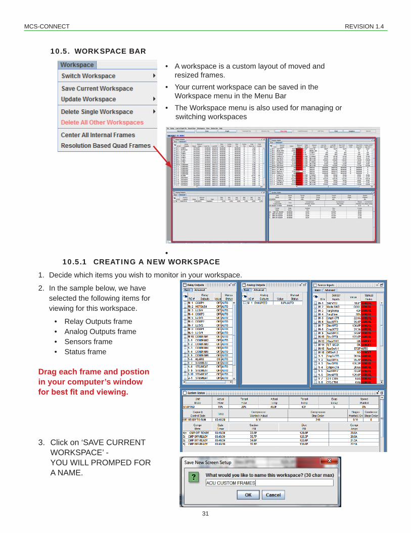
10.5. WORKSPACE BAR
• A workspace is a custom layout of moved and resized frames.• Your current workspace can be saved in the Workspace menu in the Menu Bar• The Workspace menu is also used for managing or
switching workspaces
• 10.5.1 CREATING A NEW WORKSPACE
1. Decide which items you wish to monitor in your workspace.
2. In the sample below, we have selected the following items for viewing for this workspace.
• Relay Outputs frame• Analog Outputs frame• Sensors frame• Status frame
Drag each frame and postion in your computer’s window for best fit and viewing.
3. Click on ‘SAVE CURRENT WORKSPACE’ - YOU WILL PROMPED FOR A NAME.
MCS-CONNECT REVISION 1.4
32
After creating and saving a workspace, continue to view other options under the ‘Workspace Menu Bar’
10.5.2 Switch Workspace - User can select different ‘SAVED WORKSPACES’ 10.5.3 Save Current Workspace - Choose the items you wish to view and save the current
workspace.
NOTE: At the ‘GENERAL SETUP SCREEN’ in MCS-CONNECT you can choose a workspace as your default workspace so each time you connect to your controller, your custom workspace will appear. You can change back to the default workspace or create a new workspace.
10.5.4 Update Workspace - If you make changes to your saved workspace, click to ‘Update’ the workspace.
10.5.5 Delete Single Workspace - click to delete a single workspace.
10.5.6 Delete All Other Workspaces - deletes all workspaces except the current workspace
10.5.7 Center all Internal Frames- Click here and each open frame will be centered in your viewing area.
10.5.8 Resolution Based Quad Frames - Click here and four frames will center within your viewing area.
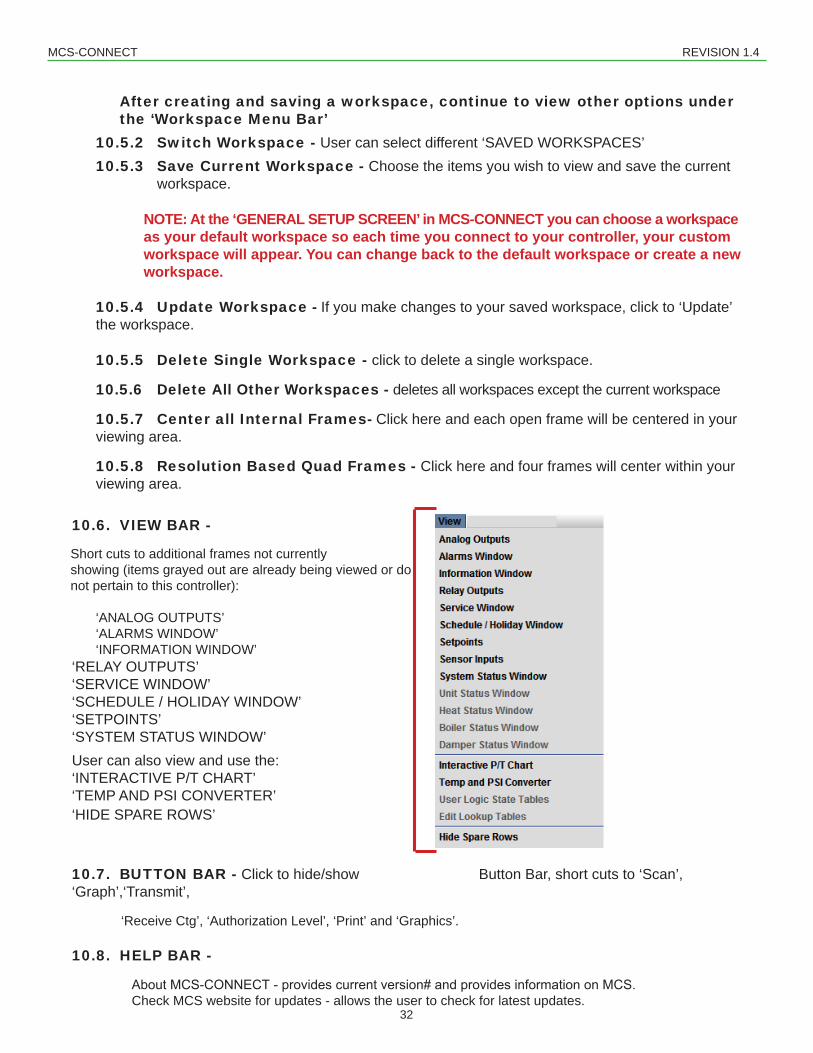
10.6. VIEW BAR -
Short cuts to additional frames not currently showing (items grayed out are already being viewed or do not pertain to this controller):
‘RELAY OUTPUTS’‘SERVICE WINDOW’‘SCHEDULE / HOLIDAY WINDOW’‘SETPOINTS’‘SYSTEM STATUS WINDOW’User can also view and use the:‘INTERACTIVE P/T CHART’‘TEMP AND PSI CONVERTER’‘HIDE SPARE ROWS’
10.7. BUTTON BAR - Click to hide/show Button Bar, short cuts to ‘Scan’, ‘Graph’,‘Transmit’,
‘Receive Ctg’, ‘Authorization Level’, ‘Print’ and ‘Graphics’.
10.8. HELP BAR -
AboutMCS-CONNECT-providescurrentversion#andprovidesinformationonMCS.Check MCS website for updates - allows the user to check for latest updates.
MCS-CONNECT REVISION 1.4
33
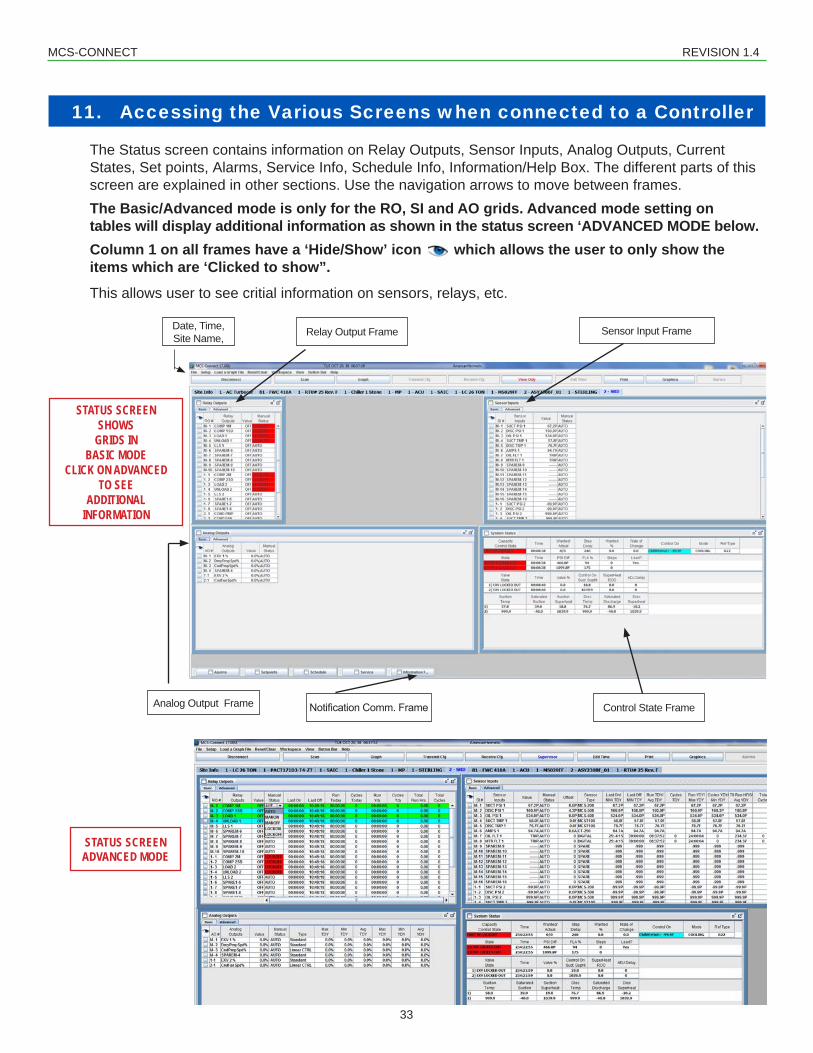
11. Accessing the Various Screens when connected to a Controller The Status screen contains information on Relay Outputs, Sensor Inputs, Analog Outputs, Current States, Set points, Alarms, Service Info, Schedule Info, Information/Help Box. The different parts of this screen are explained in other sections. Use the navigation arrows to move between frames.The Basic/Advanced mode is only for the RO, SI and AO grids. Advanced mode setting on tables will display additional information as shown in the status screen ‘ADVANCED MODE below. Column 1 on all frames have a ‘Hide/Show’ icon which allows the user to only show the items which are ‘Clicked to show”.
This allows user to see critial information on sensors, relays, etc.
Relay Output FrameDate, Time, Site Name,
Analog Output Frame Control State FrameNotificationComm.Frame
Sensor Input Frame
STATUS SCREEN SHOWS
GRIDS IN BASIC MODE
CLICK ON ADVANCED TO SEE
ADDITIONAL INFORMATION
STATUS SCREEN ADVANCED MODE
MCS-CONNECT REVISION 1.4
34
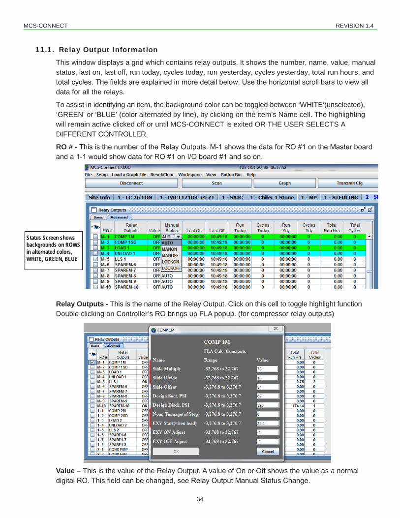
11.1. Relay Output Information
This window displays a grid which contains relay outputs. It shows the number, name, value, manual status, last on, last off, run today, cycles today, run yesterday, cycles yesterday, total run hours, and totalcycles.Thefieldsareexplainedinmoredetailbelow.Usethehorizontalscrollbarstoviewalldata for all the relays.
To assist in identifying an item, the background color can be toggled between ‘WHITE‘(unselected), ‘GREEN’ or ‘BLUE’ (color alternated by line), by clicking on the item’s Name cell. The highlighting will remain active clicked off or until MCS-CONNECT is exited OR THE USER SELECTS A DIFFERENT CONTROLLER.
Relay Outputs - This is the name of the Relay Output. Click on this cell to toggle highlight functionDouble clicking on Controller’s RO brings up FLA popup. (for compressor relay outputs)
Value – This is the value of the Relay Output. A value of On or Off shows the value as a normal digitalRO.Thisfieldcanbechanged,seeRelayOutputManualStatusChange.
Status Screen shows backgrounds on ROWS in alternated colors, WHITE, GREEN, BLUE
MCS-CONNECT REVISION 1.4
35
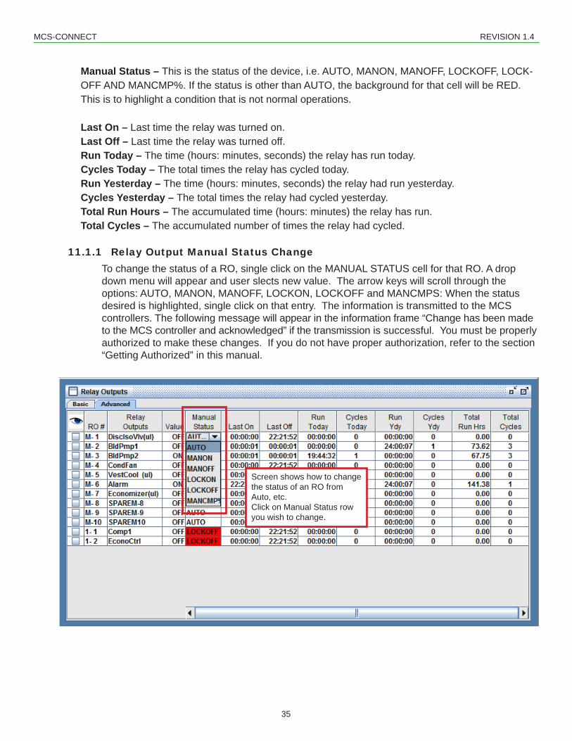
Manual Status – This is the status of the device, i.e. AUTO, MANON, MANOFF, LOCKOFF, LOCK-OFF AND MANCMP%. If the status is other than AUTO, the background for that cell will be RED. This is to highlight a condition that is not normal operations.
Last On – Last time the relay was turned on.Last Off – Last time the relay was turned off.Run Today – The time (hours: minutes, seconds) the relay has run today.Cycles Today – The total times the relay has cycled today.Run Yesterday – The time (hours: minutes, seconds) the relay had run yesterday.Cycles Yesterday – The total times the relay had cycled yesterday.Total Run Hours – The accumulated time (hours: minutes) the relay has run.Total Cycles – The accumulated number of times the relay had cycled.
11.1.1 Relay Output Manual Status ChangeTo change the status of a RO, single click on the MANUAL STATUS cell for that RO. A drop down menu will appear and user slects new value. The arrow keys will scroll through the options: AUTO, MANON, MANOFF, LOCKON, LOCKOFF and MANCMPS: When the status desired is highlighted, single click on that entry. The information is transmitted to the MCS controllers. The following message will appear in the information frame “Change has been made to the MCS controller and acknowledged” if the transmission is successful. You must be properly authorized to make these changes. If you do not have proper authorization, refer to the section “Getting Authorized” in this manual.
Screen shows how to change the status of an RO from Auto, etc.Click on Manual Status row you wish to change.
MCS-CONNECT REVISION 1.4
36
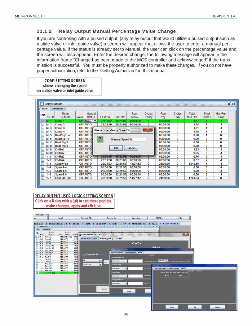
11.1.2 Relay Output Manual Percentage Value ChangeIf you are controlling with a pulsed output, (any relay output that would utilize a pulsed output such as a slide valve or inlet guide valve) a screen will appear that allows the user to enter a manual per-centage value. If the status is already set to Manual, the user can click on the percentage value and the screen will also appear. Enter the desired change, the following message will appear in the information frame “Change has been made to the MCS controller and acknowledged” if the trans-mission is successful. You must be properly authorized to make these changes. If you do not have proper authorization, refer to the “Getting Authorized” in this manual.
RELAY OUTPUT USER LOGIC SETTING SCREENClick on a Relay with a (ul) to see these popups.
make changes, apply and click ok.
COMP SETTING SCREENshows changing the speed
on a slide valve or inlet guide valve
MCS-CONNECT REVISION 1.4
37
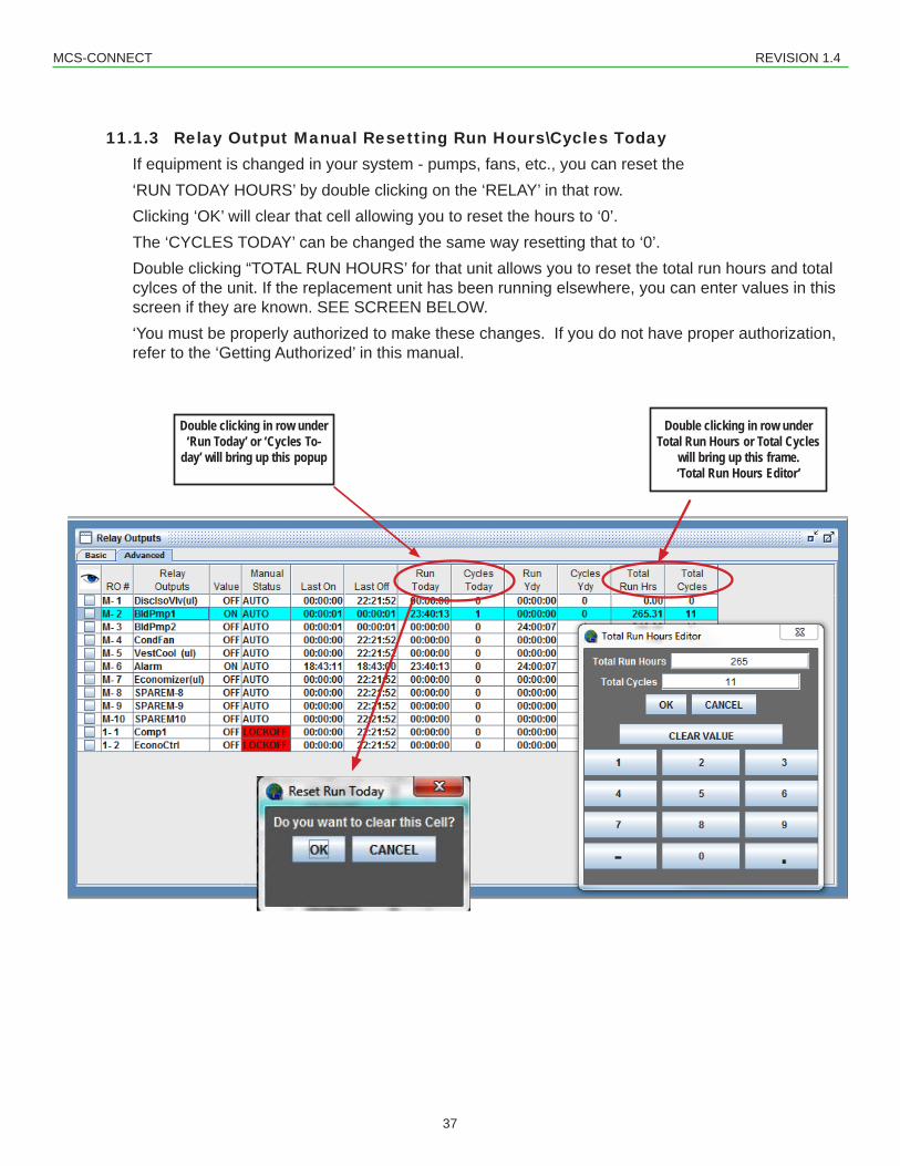
11.1.3 Relay Output Manual Resetting Run Hours\Cycles TodayIf equipment is changed in your system - pumps, fans, etc., you can reset the ‘RUN TODAY HOURS’ by double clicking on the ‘RELAY’ in that row. Clicking ‘OK’ will clear that cell allowing you to reset the hours to ‘0’.The ‘CYCLES TODAY’ can be changed the same way resetting that to ‘0’.Double clicking “TOTAL RUN HOURS’ for that unit allows you to reset the total run hours and total cylces of the unit. If the replacement unit has been running elsewhere, you can enter values in this screen if they are known. SEE SCREEN BELOW.‘You must be properly authorized to make these changes. If you do not have proper authorization, refer to the ‘Getting Authorized’ in this manual.
Double clicking in row under Total Run Hours or Total Cycles
will bring up this frame.‘Total Run Hours Editor’
Double clicking in row under ‘Run Today’ or ‘Cycles To-
day’ will bring up this popup
MCS-CONNECT REVISION 1.4
38
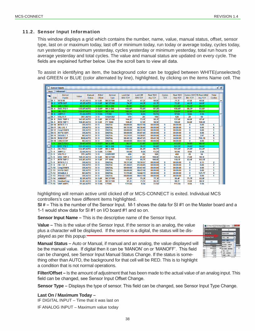
11.2. Sensor Input InformationThis window displays a grid which contains the number, name, value, manual status, offset, sensor type, last on or maximum today, last off or minimum today, run today or average today, cycles today, run yesterday or maximum yesterday, cycles yesterday or minimum yesterday, total run hours or average yesterday and total cycles. The value and manual status are updated on every cycle. The fieldsareexplainedfurtherbelow.Usethescrollbarstoviewalldata.
To assist in identifying an item, the background color can be toggled between WHITE(unselected) and GREEN or BLUE (color alternated by line), highlighted, by clicking on the items Name cell. The
highlighting will remain active until clicked off or MCS-CONNECT is exited. Individual MCS controllers’s can have different items highlighted.SI # – ThisisthenumberoftheSensorInput.M-1showsthedataforSI#1ontheMasterboardanda1-1wouldshowdataforSI#1onI/Oboard#1andsoon.Sensor Input Name – This is the descriptive name of the Sensor Input.Value – This is the value of the Sensor Input. If the sensor is an analog, the value plus a character will be displayed. If the sensor is a digital, the status will be dis-played as per this popup: Manual Status – Auto or Manual, if manual and an analog, the value displayed will bethemanualvalue.Ifdigitalthenitcanbe‘MANON’onor‘MANOFF’.Thisfieldcan be changed, see Sensor Input Manual Status Change. If the status is some-thing other than AUTO, the background for that cell will be RED. This is to highlight a condition that is not normal operations.Filter/Offset – Is the amount of adjustment that has been made to the actual value of an analog input. This fieldcanbechanged,seeSensorInputOffsetChange.Sensor Type – Displaysthetypeofsensor.Thisfieldcanbechanged,seeSensorInputTypeChange.
Last On / Maximum Today – IF DIGITAL INPUT – Time that it was last onIF ANALOG INPUT – Maximum value today
MCS-CONNECT REVISION 1.4
39
Last Off / Minimum TodayIF DIGITAL INPUT – Time that it was last offIF ANALOG INPUT – Minimum value today
Run Today / Average TodayIF DIGITAL INPUT – Total time on todayIF ANALOG INPUT – Average today value of sensor
Cycles Today - Digital only, total number of time the sensor cycled today
Run YESTERDAY / Maximum YESTERDAYIF DIGITAL INPUT – Total time yesterdayIF ANALOG INPUT – Maximum value of sensor
Cycles YESTERDAY / Minimum YESTERDAY IF DIGITAL INPUT – Total cycles yesterdayIF ANALOG INPUT – Minimum value of sensor
Total Run Hours / Average YESTERDAYIF DIGITAL INPUT – Total time on yesterdayIF ANALOG INPUT – Average value of sensor
Total Cycles - - Digital only, total number of times the sensor cycled
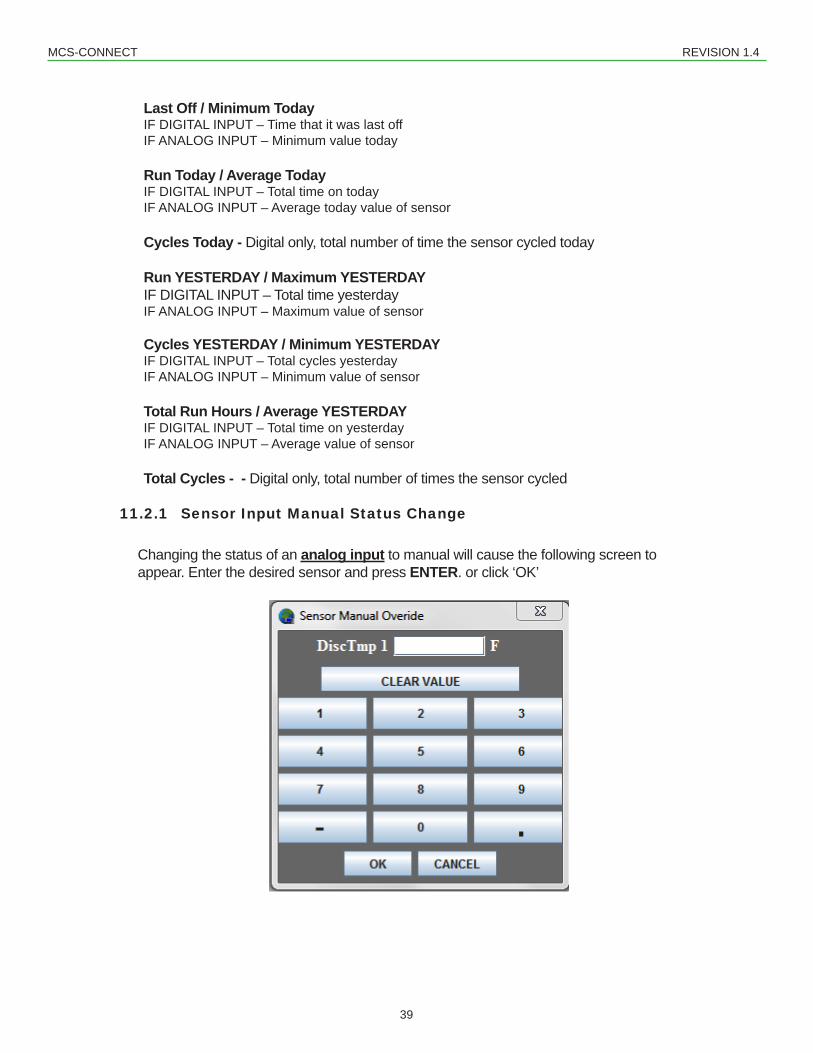
11.2.1 Sensor Input Manual Status Change
Changing the status of an analog input to manual will cause the following screen toappear. Enter the desired sensor and press ENTER. or click ‘OK’
MCS-CONNECT REVISION 1.4
40
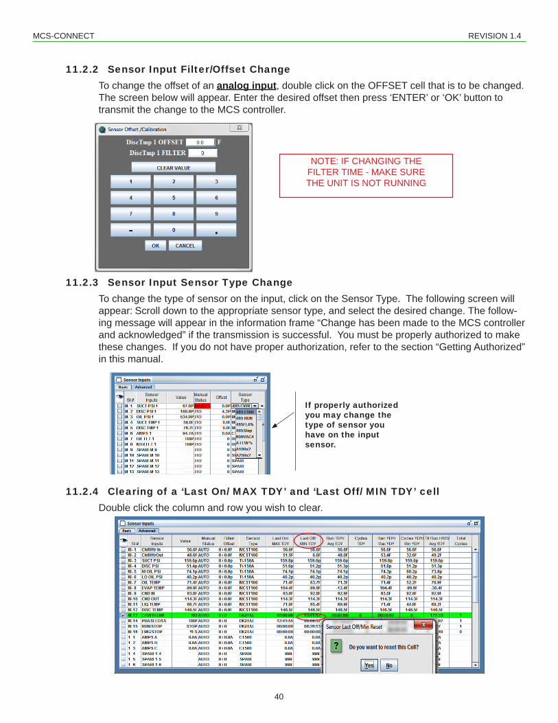
11.2.2 Sensor Input Filter/Offset ChangeTo change the offset of an analog input, double click on the OFFSET cell that is to be changed. The screen below will appear. Enter the desired offset then press ‘ENTER’ or ‘OK’ button to transmit the change to the MCS controller.
11.2.3 Sensor Input Sensor Type ChangeTo change the type of sensor on the input, click on the Sensor Type. The following screen will appear: Scroll down to the appropriate sensor type, and select the desired change. The follow-ing message will appear in the information frame “Change has been made to the MCS controller and acknowledged” if the transmission is successful. You must be properly authorized to make these changes. If you do not have proper authorization, refer to the section “Getting Authorized” in this manual.
11.2.4 Clearing of a ‘Last On/ MAX TDY’ and ‘Last Off/ MIN TDY’ cellDouble click the column and row you wish to clear.
If properly authorized you may change the type of sensor you have on the input sensor.
NOTE: IF CHANGING THE FILTER TIME - MAKE SURE THE UNIT IS NOT RUNNING
MCS-CONNECT REVISION 1.4
41
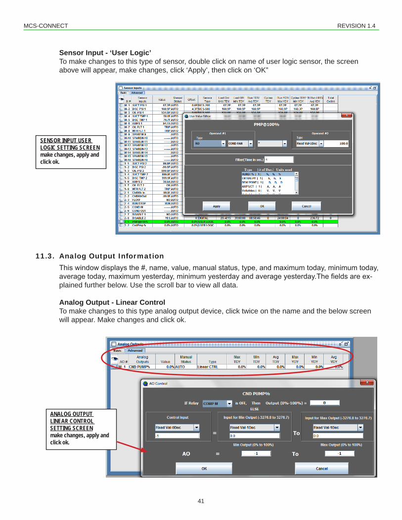
Sensor Input - ‘User Logic’To make changes to this type of sensor, double click on name of user logic sensor, the screen above will appear, make changes, click ‘Apply’, then click on ‘OK”
11.3. Analog Output InformationThiswindowdisplaysthe#,name,value,manualstatus,type,andmaximumtoday,minimumtoday,averagetoday,maximumyesterday,minimumyesterdayandaverageyesterday.Thefieldsareex-plained further below. Use the scroll bar to view all data.
Analog Output - Linear ControlTo make changes to this type analog output device, click twice on the name and the below screen will appear. Make changes and click ok.
SENSOR INPUT USER LOGIC SETTING SCREENmake changes, apply and click ok.
ANALOG OUTPUT LINEAR CONTROL SETTING SCREENmake changes, apply and click ok.
MCS-CONNECT REVISION 1.4
42
To assist in identifying an item, the background color can be toggled between WHITE, normal, and GREEN or BLUE (color alternated by line), highlighted, by clicking on the items Name cell. The highlighting will remain active until clicked off or MCS-CONNECT is exited. Individual MCS controllers’s can have different items highlighted and this will not be lost when moving between units.
AO # – This is the number of the Analog Output. M-1 shows the data for the 1st AO on the Master board. The MCS-8 has 1 AO on the master. The Magnum has 4 AO’s on the master. A 1-1 would showdataforAO#1onI/Oboard#1andsoon.
Analog Output Name – This is the name of the Analog Output. Click on this cell to toggle highlight function.
Value – This is the current percentage value of the analog output.
Manual Status - This is the status of the device, i.e. auto, manual. If the device is in ‘Manual’. thentheinformationinthevaluefieldisforthemanualsetting.IfthedeviceisnotinAUTOstatus,the background for this cell will be RED.
Maximum Today – Thisisthemaximumvaluethathasoccurredinthevaluefieldtoday.
Average Today - Thisistheaveragevaluethathasoccurredinthevaluefieldtoday.
Maximum Yesterday - Thisisthemaximumvaluethatoccurredinthevaluefieldyesterday.
Minimum Yesterday - This is the minimum value that occurred in the value yesterday.
Average Yesterday - Thisistheaveragevaluethatoccurredinthevaluefieldyesterday.
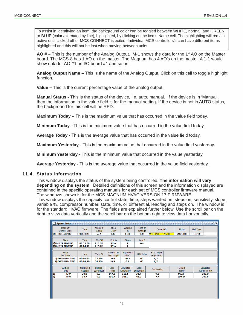
11.4. Status InformationThis window displays the status of the system being controlled. The information will vary depending on the system.DetaileddefinitionsofthisscreenandtheinformationdisplayedarecontainedinthespecificoperatingmanualsforeachsetofMCScontrollerfirmwaremanual..The windows shown is for the MCS-MAGNUM HVAC VERSION 17 FIRMWARE.This window displays the capacity control state, time, steps wanted on, steps on, sensitivity, slope, variable %, compressor number, state, time, oil differential, lead/lag and steps on. The window is forthestandardHVACfirmware.Thefieldsareexplainedfurtherbelow.Usethescrollbarontheright to view data vertically and the scroll bar on the bottom right to view data horizontally.
MCS-CONNECT REVISION 1.4
43
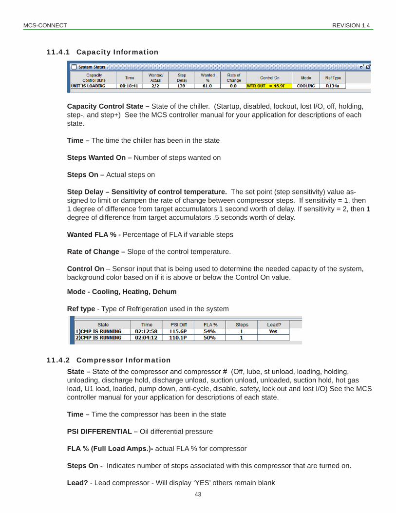
11.4.1 Capacity Information
Capacity Control State – State of the chiller. (Startup, disabled, lockout, lost I/O, off, holding, step-, and step+) See the MCS controller manual for your application for descriptions of each state.
Time – The time the chiller has been in the state
Steps Wanted On – Number of steps wanted on
Steps On – Actual steps on
Step Delay – Sensitivity of control temperature. The set point (step sensitivity) value as-signed to limit or dampen the rate of change between compressor steps. If sensitivity = 1, then 1 degree of difference from target accumulators 1 second worth of delay. If sensitivity = 2, then 1 degree of difference from target accumulators .5 seconds worth of delay.
Wanted FLA % - Percentage of FLA if variable steps
Rate of Change – Slope of the control temperature.
Control On – Sensor input that is being used to determine the needed capacity of the system, background color based on if it is above or below the Control On value.
Mode - Cooling, Heating, Dehum
Ref type - Type of Refrigeration used in the system
11.4.2 Compressor InformationState – Stateofthecompressorandcompressor#(Off,lube,stunload,loading,holding,unloading, discharge hold, discharge unload, suction unload, unloaded, suction hold, hot gas load, U1 load, loaded, pump down, anti-cycle, disable, safety, lock out and lost I/O) See the MCS controller manual for your application for descriptions of each state.
Time – Time the compressor has been in the state
PSI DIFFERENTIAL – Oil differential pressure
FLA % (Full Load Amps.)- actual FLA % for compressor
Steps On - Indicates number of steps associated with this compressor that are turned on.
Lead? - Lead compressor - Will display ‘YES’ others remain blank
MCS-CONNECT REVISION 1.4
44
11.4.3 Compressor/Superheat Info
Suction Temp – Compressor number and current valve of the Suction Temperature, if available.
Saturated Suction – Calculated Suction Saturated Temperature, if available. The Suction Pressure is converted into temperature based upon the type of refrigerant (R22, R134a, R407c, and R410a are supported.)
Suction Superheat – Calculated Suction SUPERHEAT, only available if both the Suction Temperature and the Suction Pressure are used. The calculation is Suction Temperature minus the Suction Saturated Temperature.
Disc Temp – Discharge Temperature, if available
Saturated Discharge – Calculated Discharge Saturated Temperature, if available. The Discharge pressure is converted into temperature based upon the type of refrigerant (R22, R134a, R407c, and R410a are supported.)
Disc Superheat – Calculated Discharge SUPERHEAT, only available if both the Discharge Temperature and the Discharge Pressure are used. The calculation is Discharge Temperature minus the Discharge Saturated Temperature.
Subcooling – the amount of heat removed below the refrigerants condensing temperature at a particular pressure measured in deg. F
Liquid Temp – The temperature of the refrigerant.
Saturated Liquid Temp. – Temperatue and pressure of refrigerant.
11.4.4 EXV Info
Evap EXV State – Compressor number and current valve of the EXV.
Time – The time the valve has been in this state.
Valve % – This is the current valve % opening. While 0 to 100 % is the range, there are set points that limit the range to avoid unnecessary movement outside the required operating range.
Control on Suction Superheat – The current superheat for this circuit.
ADJ Delay – When this value reaches zero the controller will adjust the EXV based on the current status.
EXV Target (Adjusted) – The adjusted value of the EXV based on setpoints.
MCS-CONNECT REVISION 1.4
45
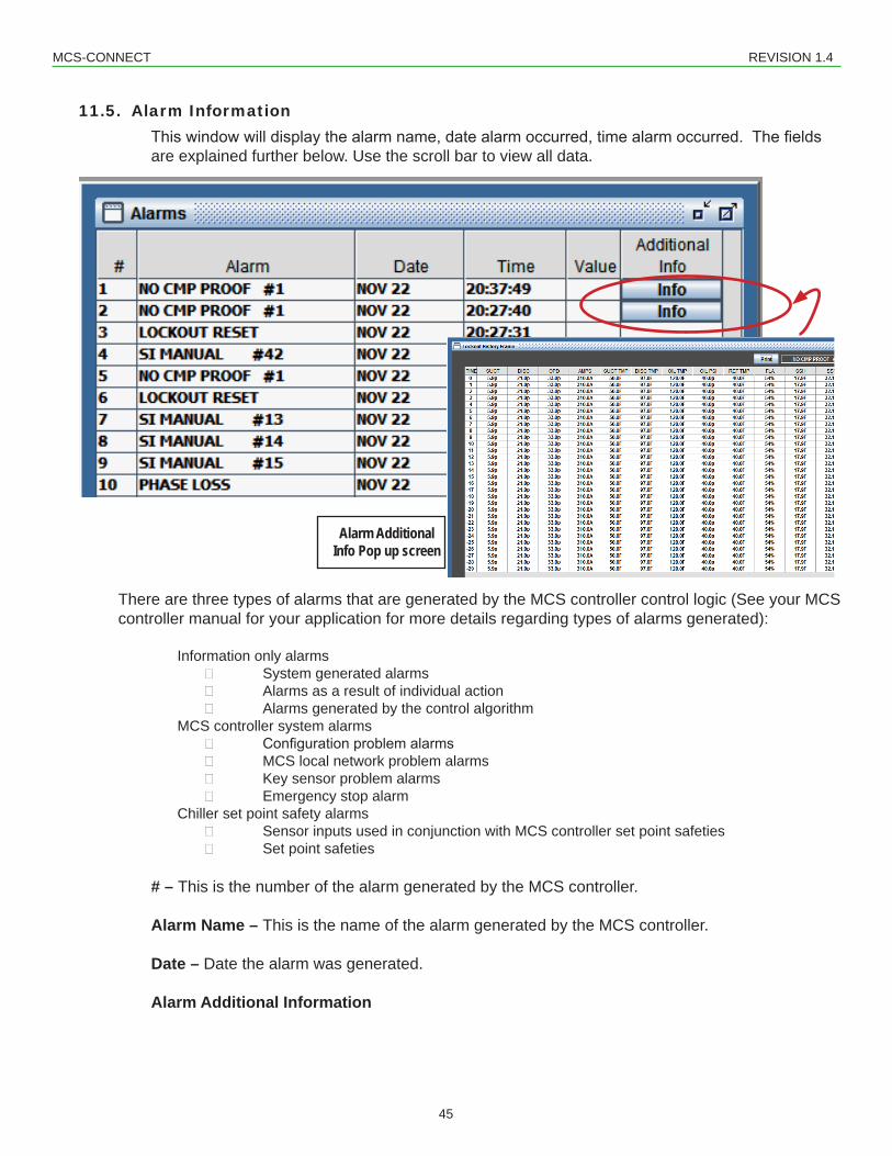
11.5. Alarm InformationThiswindowwilldisplaythealarmname,datealarmoccurred,timealarmoccurred.Thefieldsare explained further below. Use the scroll bar to view all data.
There are three types of alarms that are generated by the MCS controller control logic (See your MCS controller manual for your application for more details regarding types of alarms generated):
Information only alarms System generated alarms Alarms as a result of individual action Alarms generated by the control algorithm
MCS controller system alarms Configurationproblemalarms MCS local network problem alarms Key sensor problem alarms Emergency stop alarm
Chiller set point safety alarms Sensor inputs used in conjunction with MCS controller set point safeties Set point safeties
# – This is the number of the alarm generated by the MCS controller.
Alarm Name – This is the name of the alarm generated by the MCS controller.
Date – Date the alarm was generated.
Alarm Additional Information
Alarm AdditionalInfo Pop up screen
MCS-CONNECT REVISION 1.4
46
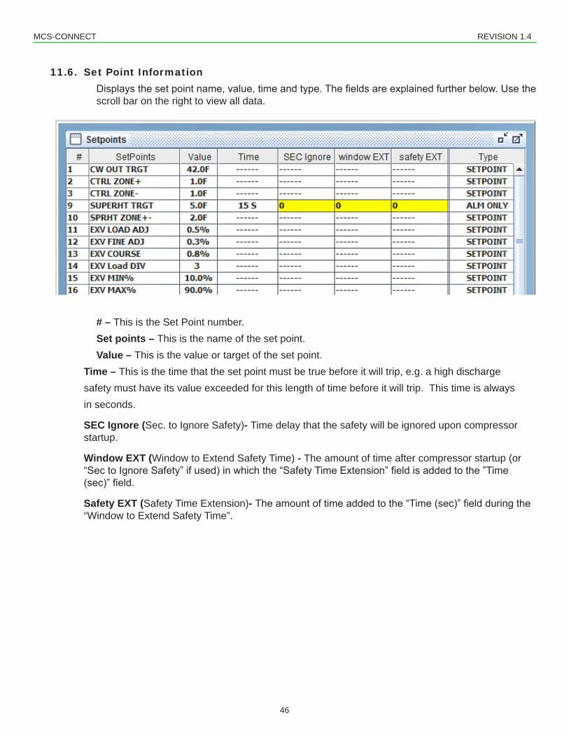
11.6. Set Point InformationDisplaysthesetpointname,value,timeandtype.Thefieldsareexplainedfurtherbelow.Usethescroll bar on the right to view all data.
# – This is the Set Point number.Set points – This is the name of the set point.Value – This is the value or target of the set point.
Time – This is the time that the set point must be true before it will trip, e.g. a high discharge safety must have its value exceeded for this length of time before it will trip. This time is always in seconds.
SEC Ignore (Sec. to Ignore Safety)- Time delay that the safety will be ignored upon compressor startup.
Window EXT (Window to Extend Safety Time) - The amount of time after compressor startup (or “SectoIgnoreSafety”ifused)inwhichthe“SafetyTimeExtension”fieldisaddedtothe”Time(sec)”field.
Safety EXT (Safety Time Extension)- Theamountoftimeaddedtothe“Time(sec)”fieldduringthe“Window to Extend Safety Time”.
MCS-CONNECT REVISION 1.4
47
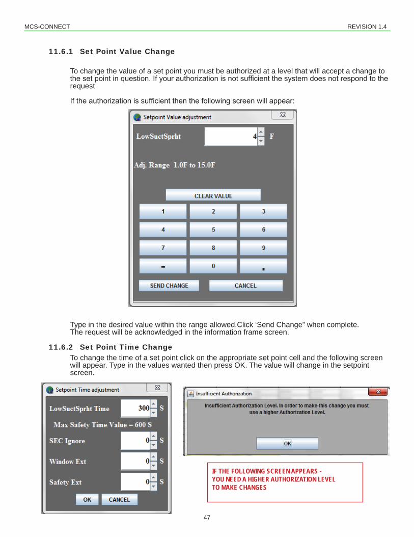
11.6.1 Set Point Value Change
To change the value of a set point you must be authorized at a level that will accept a change to thesetpointinquestion.Ifyourauthorizationisnotsufficientthesystemdoesnotrespondtotherequest Iftheauthorizationissufficientthenthefollowingscreenwillappear:
Type in the desired value within the range allowed.Click ‘Send Change” when complete. The request will be acknowledged in the information frame screen.
11.6.2 Set Point Time ChangeTo change the time of a set point click on the appropriate set point cell and the following screen will appear. Type in the values wanted then press OK. The value will change in the setpoint screen.
IF THE FOLLOWING SCREEN APPEARS - YOU NEED A HIGHER AUTHORIZATION LEVEL TO MAKE CHANGES
MCS-CONNECT REVISION 1.4
48
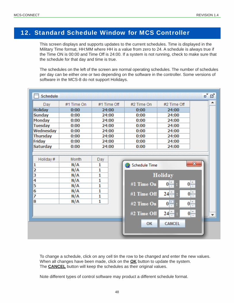
This screen displays and supports updates to the current schedules. Time is displayed in the Military Time format, HH:MM where HH is a value from zero to 24. A schedule is always true if the Time ON is 00:00 and Time Off is 24:00. If a system is not running, check to make sure that the schedule for that day and time is true.
The schedules on the left of the screen are normal operating schedules. The number of schedules per day can be either one or two depending on the software in the controller. Some versions of software in the MCS-8 do not support Holidays.
To change a schedule, click on any cell tin the row to be changed and enter the new values. When all changes have been made, click on the OK button to update the system. The CANCEL button will keep the schedules as their original values.
Note different types of control software may product a different schedule format.
12. Standard Schedule Window for MCS Controller
MCS-CONNECT REVISION 1.4
49
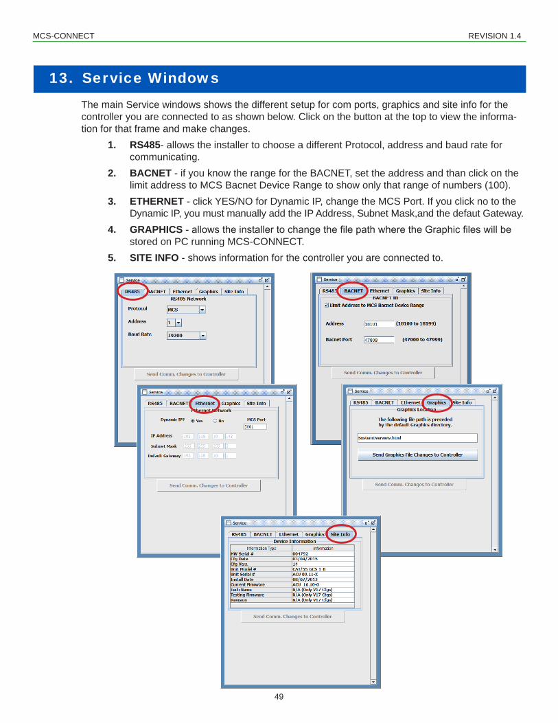
13. Service WindowsThe main Service windows shows the different setup for com ports, graphics and site info for the controller you are connected to as shown below. Click on the button at the top to view the informa-tion for that frame and make changes.
1. RS485- allows the installer to choose a different Protocol, address and baud rate for communicating.
2. BACNET - if you know the range for the BACNET, set the address and than click on the limit address to MCS Bacnet Device Range to show only that range of numbers (100).
3. ETHERNET - click YES/NO for Dynamic IP, change the MCS Port. If you click no to the Dynamic IP, you must manually add the IP Address, Subnet Mask,and the defaut Gateway.
4. GRAPHICS-allowstheinstallertochangethefilepathwheretheGraphicfileswillbestored on PC running MCS-CONNECT.
5. SITE INFO - shows information for the controller you are connected to.
MCS-CONNECT REVISION 1.4
50
14. Graph Capabilities Screen of MCS Controllers
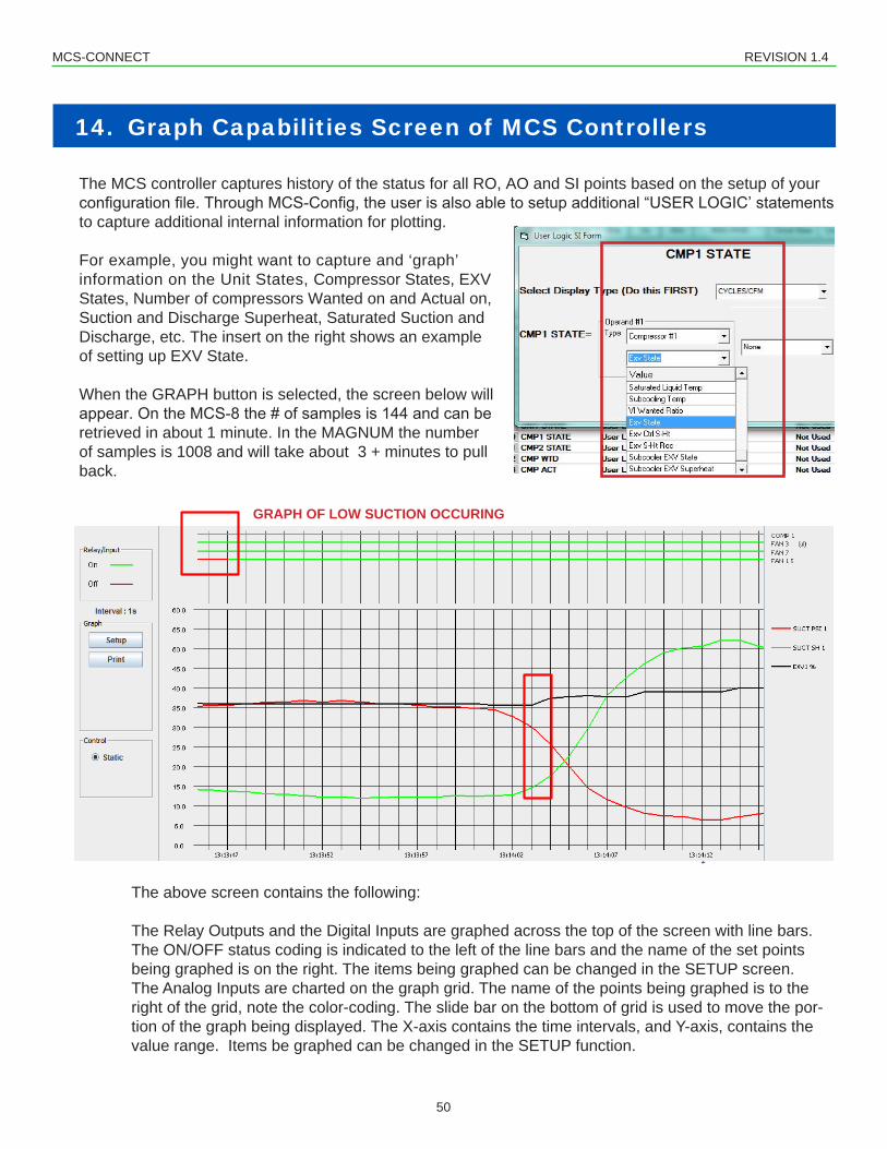
The MCS controller captures history of the status for all RO, AO and SI points based on the setup of your configurationfile.ThroughMCS-Config,theuserisalsoabletosetupadditional“USERLOGIC’statementsto capture additional internal information for plotting.
For example, you might want to capture and ‘graph’ information on the Unit States, Compressor States, EXV States, Number of compressors Wanted on and Actual on, Suction and Discharge Superheat, Saturated Suction and Discharge, etc. The insert on the right shows an example of setting up EXV State.
When the GRAPH button is selected, the screen below will appear.OntheMCS-8the#ofsamplesis144andcanberetrieved in about 1 minute. In the MAGNUM the number of samples is 1008 and will take about 3 + minutes to pull back.
The above screen contains the following:
The Relay Outputs and the Digital Inputs are graphed across the top of the screen with line bars. The ON/OFF status coding is indicated to the left of the line bars and the name of the set points being graphed is on the right. The items being graphed can be changed in the SETUP screen.The Analog Inputs are charted on the graph grid. The name of the points being graphed is to the right of the grid, note the color-coding. The slide bar on the bottom of grid is used to move the por-tion of the graph being displayed. The X-axis contains the time intervals, and Y-axis, contains the value range. Items be graphed can be changed in the SETUP function.
GRAPH OF LOW SUCTION OCCURING
Notice the 3rd stage of condensing comes on
15 seconds later the suction psi crashes
GRAPH OF LOW SUCTION OCCURING
MCS-CONNECT REVISION 1.4
51
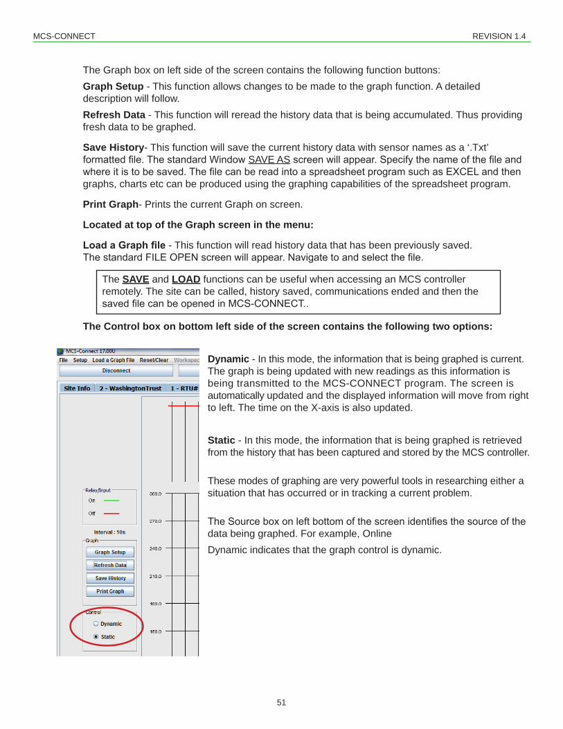
The Graph box on left side of the screen contains the following function buttons:Graph Setup - This function allows changes to be made to the graph function. A detailed description will follow.Refresh Data - This function will reread the history data that is being accumulated. Thus providing fresh data to be graphed.
Save History- This function will save the current history data with sensor names as a ‘.Txt’ formattedfile.ThestandardWindowSAVE ASscreenwillappear.Specifythenameofthefileandwhereitistobesaved.ThefilecanbereadintoaspreadsheetprogramsuchasEXCELandthengraphs, charts etc can be produced using the graphing capabilities of the spreadsheet program.
Print Graph- Prints the current Graph on screen.
Located at top of the Graph screen in the menu:
Load a Graph file - This function will read history data that has been previously saved. ThestandardFILEOPENscreenwillappear.Navigatetoandselectthefile.
The Control box on bottom left side of the screen contains the following two options:
Dynamic - In this mode, the information that is being graphed is current. The graph is being updated with new readings as this information is being transmitted to the MCS-CONNECT program. The screen is automatically updated and the displayed information will move from right to left. The time on the X-axis is also updated.
Static - In this mode, the information that is being graphed is retrieved from the history that has been captured and stored by the MCS controller. These modes of graphing are very powerful tools in researching either a situation that has occurred or in tracking a current problem.
TheSourceboxonleftbottomofthescreenidentifiesthesourceofthedata being graphed. For example, Online Dynamic indicates that the graph control is dynamic.
The SAVE and LOAD functions can be useful when accessing an MCS controller remotely. The site can be called, history saved, communications ended and then the savedfilecanbeopenedinMCS-CONNECT..
MCS-CONNECT REVISION 1.4
52
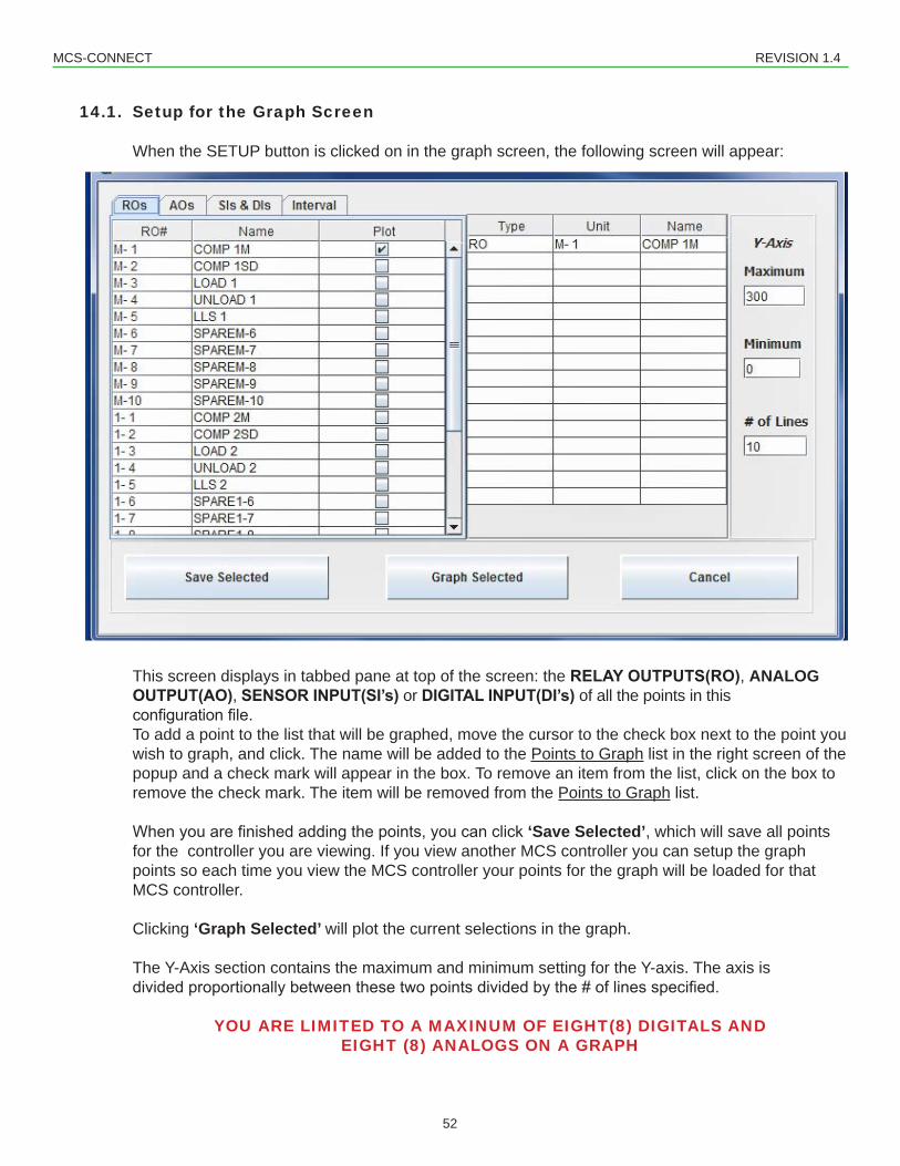
14.1. Setup for the Graph Screen
When the SETUP button is clicked on in the graph screen, the following screen will appear:
This screen displays in tabbed pane at top of the screen: the RELAY OUTPUTS(RO), ANALOG OUTPUT(AO), SENSOR INPUT(SI’s) or DIGITAL INPUT(DI’s) of all the points in this configurationfile.To add a point to the list that will be graphed, move the cursor to the check box next to the point you wish to graph, and click. The name will be added to the Points to Graph list in the right screen of the popup and a check mark will appear in the box. To remove an item from the list, click on the box to remove the check mark. The item will be removed from the Points to Graph list.
Whenyouarefinishedaddingthepoints,youcanclick‘Save Selected’, which will save all points for the controller you are viewing. If you view another MCS controller you can setup the graph points so each time you view the MCS controller your points for the graph will be loaded for that MCS controller.
Clicking ‘Graph Selected’ will plot the current selections in the graph.
The Y-Axis section contains the maximum and minimum setting for the Y-axis. The axis is dividedproportionallybetweenthesetwopointsdividedbythe#oflinesspecified.
YOU ARE LIMITED TO A MAXINUM OF EIGHT(8) DIGITALS AND EIGHT (8) ANALOGS ON A GRAPH
MCS-CONNECT REVISION 1.4
53
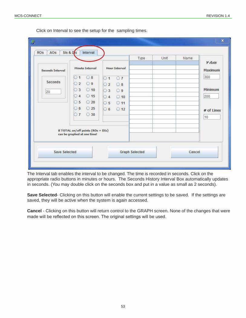
Click on Interval to see the setup for the sampling times.
The Interval tab enables the interval to be changed. The time is recorded in seconds. Click on the appropriate radio buttons in minutes or hours. The Seconds History Interval Box automatically updates in seconds. (You may double click on the seconds box and put in a value as small as 2 seconds).
Save Selected- Clicking on this button will enable the current settings to be saved. If the settings are saved, they will be active when the system is again accessed.
Cancel - Clicking on this button will return control to the GRAPH screen. None of the changes that were madewillbereflectedonthisscreen.Theoriginalsettingswillbeused.
MCS-CONNECT REVISION 1.4
54
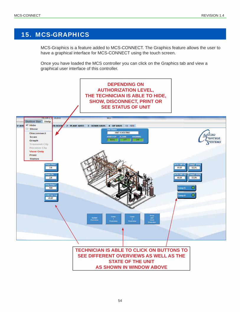
15. MCS-GRAPHICS
MCS-Graphics is a feature added to MCS-CONNECT. The Graphics feature allows the user to have a graphical interface for MCS-CONNECT using the touch screen.
Once you have loaded the MCS controller you can click on the Graphics tab and view a graphical user interface of this controller.
DEPENDING ON AUTHORIZATION LEVEL,
THE TECHNICIAN IS ABLE TO HIDE, SHOW, DISCONNECT, PRINT OR
SEE STATUS OF UNIT
TECHNICIAN IS ABLE TO CLICK ON BUTTONS TO SEE DIFFERENT OVERVIEWS AS WELL AS THE
STATE OF THE UNITAS SHOWN IN WINDOW ABOVE
MCS-CONNECT REVISION 1.4
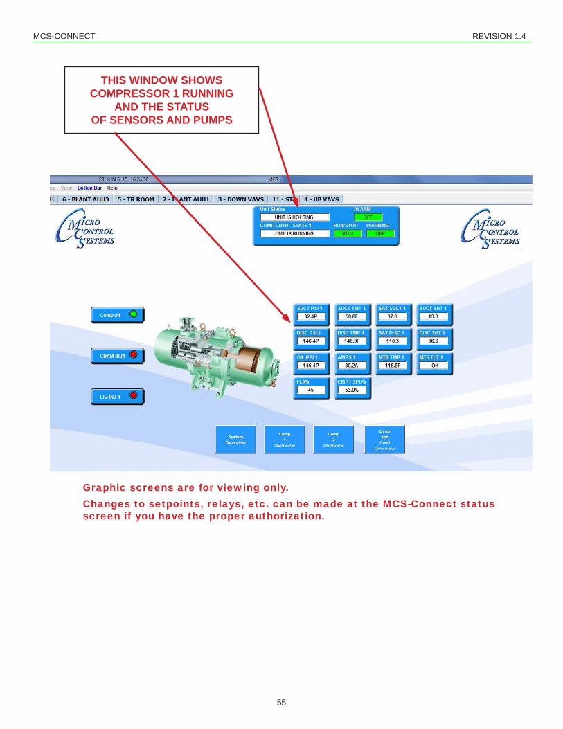
55
THIS WINDOW SHOWS COMPRESSOR 1 RUNNING
AND THE STATUS OF SENSORS AND PUMPS
Graphic screens are for viewing only. Changes to setpoints, relays, etc. can be made at the MCS-Connect status screen if you have the proper authorization.
MCS-CONNECT REVISION 1.4
56
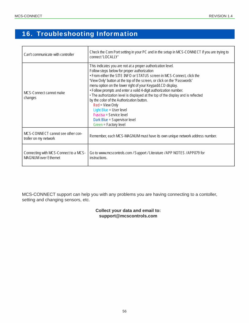
16. Troubleshooting Information
Can’t communicate with controller Check the Com Port setting in your PC and in the setup in MCS-CONNECT if you are trying to connect ‘LOCALLY’
MCS-Connect cannot makechanges
This indicates you are not at a proper authorization level.Follow steps below for proper authorization• From either the SITE INFO or STATUS screen in MCS-Connect, click the‘View Only’ button at the top of the screen, or click on the ‘Passwords’menu option on the lower right of your Keypad/LCD display.• Follow prompts and enter a valid 4-digit authorization number.• The authorization level is displayed at the top of the display and is reflectedby the color of the Authorization button.
Red = View OnlyLight Blue = User levelFuscisa = Service levelDark Blue = Supervisor levelGreen = Factory level
MCS-CONNECT cannot see other con-troller on my network Remember, each MCS-MAGNUM must have its own unique network address number.
Connecting with MCS-Connect to a MCS-MAGNUM over Ethernet
Go to www.mcscontrols.com / Support / Literature / APP NOTES / APP079 for instructions.
MCS-CONNECT support can help you with any problems you are having connecting to a contoller, setting and changing sensors, etc.
1. ConsultwithfactoryforobtainingthelatestMCS-Configfileforyourcontroller.2. DownloadthefilesendtoyoufromthefactorytoalocationonyourPCharddrive.3. Click on MCS-CONNECT to start the program.4. Click on the controller you wish to update.5. Use the ‘TRANSMIT CFG’ button to begin (you must be authorized to make this change)6. Locatethenew‘CONFIG’fileyoujustdownloadedonyourPCandbegintransmittingtothecontroller.
QuickStepsfor‘Receivinga‘Config’filefromthecontroller:1. Click on MCS-CONNECT to start the program.2. Clickonthecontrolleryouwishto“Receivetheconfigfilefrom.3. Use the ‘RECEIVE CFG’ button to begin.4. YouarepresentedwithascreenfornamingthefileandsavingtoadirectoryonyourPCharddrive.
ViewAlarms,PRINTandSAVEfileforviewing
1. Click on controller you wish to view2. Clickon‘ALARMS’,under‘AdditionalInfo,clickon‘ALARM#,toviewinfo3. Savefileforthis‘ALARM’lockouttofileonPCtothedirectory/‘MCS’/‘ALARMS’4. File can be printed using a .txt editor ‘NOTEPAD’ or can be opened in ‘EXCEL’5. Clickon‘EXCEL’,clickon‘ALLFILES’atbottomtoviewthe.txtgraphfileyousaved6. Printfile
Quick steps for setting up ‘Graphing’
1. Locatecontrollertosetup‘GRAPHING’file2. Click on ‘GRAPH’ button at the top of the frame3. Click on ‘GRAPH SETUP’ to pick ‘RELAY OUTPUTS’, ‘ANALOG OUTPUTS’, ‘SENSOR OR DIGITAL
INPUTS’ and setting the ‘INTERVAL’ (time) for the ‘GRAPH’ report.4. Click on ‘SAVE SELECT’ (clicking on this button will enable the current settings to be saved and will
be active when the controller is again accessed) or ‘GRAPH SELECTED’ (will plot the current points selectedoverthespecifiedY-Axisandwillnotbeactivewhenthecontrollerisagainaccessed).
5. History will be pulled from the controller and can be viewed on your PC or:6. Clickon‘PRINT’whichwillsavethecurrent‘GRAPH’toafileonyourPC7. LocatedthefileonyourPCtoprintahardcopy8. File can be printed using a .txt editor ‘NOTEPAD’ or can be opened in ‘EXCEL’9. Clickon‘EXCEL’,clickon‘ALLFILES’atbottomtoviewthe.txtgraphfileyousaved10. Printfile
MCS-CONNECT REVISION 1.4
58
Loading new ‘Firmware’ to the controller (AUTHORIZATION LEVEL - SUPERVISOR OR HIGHER)YOU MUST BE LOCALLY CONNECTED TO THE CONTROLLER directly at the job site.NOTE: Important: VERSION XX FIRMWARE MUST USE VERSION XX CONFIGURATION FILES. MIXED FIRMWARE AND CONFIG FILE WILL NOT WORK. MAKE SURE YOU HAVE THE LATEST FILES PRIOR TO LOADING NEW FIREMWARE TO YOUR CONTROLLER.Be sure to use the latest MCS-Connect and MCS-Config programs.
1. Consult with mcscontrols.com / [email protected] for upgrading your system2. Go to www.mcscontrols.com3. At top of main page click on ‘SUPPORT’, click on ‘MAGNUM FIRMWARE’4. Locate the latest version - server will require a ‘USERS NAME’ and password (call MCS-SUPPORT to
receive that information)5. NOTE message about upgrading your ‘FIRMWARE’ before proceeding6. Download the latest ‘VERSIONS of each software you need to upgrade’ to the directory on your PC.