64
| Date post: | 07-Jan-2023 |
| Category: |
Documents |
| Upload: | independent |
| View: | 0 times |
| Download: | 0 times |
Single Carrier FDMA | Hyung G. Myung 1
OutlineOutlineOutlineOutline
Introduction and Background
SC-FDMA Implementation in 3GPP LTE
Peak Power Characteristics of SC-FDMA Signals
Summary and Conclusions
Uplink Resource Scheduling in SC-FDMA Systems
Overview of SC-FDMA
Introduction and Background
Overview of SC-FDMA
SC-FDMA Implementation in 3GPP LTE
Peak Power Characteristics of SC-FDMA Signals
Uplink Resource Scheduling in SC-FDMA Systems
Summary and Conclusions
Single Carrier FDMA | Hyung G. Myung 3
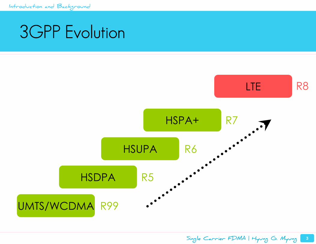
3GPP Evolution3GPP Evolution3GPP Evolution3GPP Evolution
UMTS/WCDMA
HSDPA
HSUPA
HSPA+
LTE
R99
R5
R6
R7
Introduction and Background
R8
Single Carrier FDMA | Hyung G. Myung 4
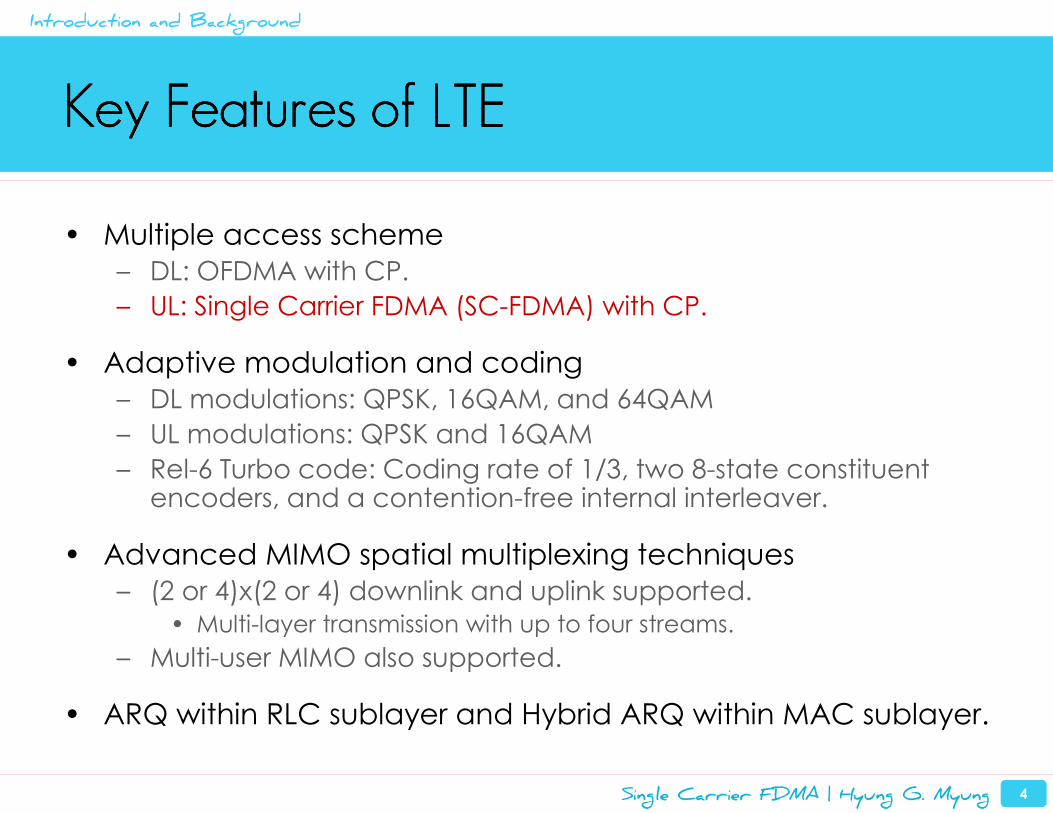
Key Features of LTEKey Features of LTEKey Features of LTEKey Features of LTE
• Multiple access scheme
– DL: OFDMA with CP.
– UL: Single Carrier FDMA (SC-FDMA) with CP.
• Adaptive modulation and coding
– DL modulations: QPSK, 16QAM, and 64QAM
– UL modulations: QPSK and 16QAM
– Rel-6 Turbo code: Coding rate of 1/3, two 8-state constituent encoders, and a contention-free internal interleaver.
• Advanced MIMO spatial multiplexing techniques
– (2 or 4)x(2 or 4) downlink and uplink supported.
• Multi-layer transmission with up to four streams.
– Multi-user MIMO also supported.
• ARQ within RLC sublayer and Hybrid ARQ within MAC sublayer.
Introduction and Background
Single Carrier FDMA | Hyung G. Myung 5
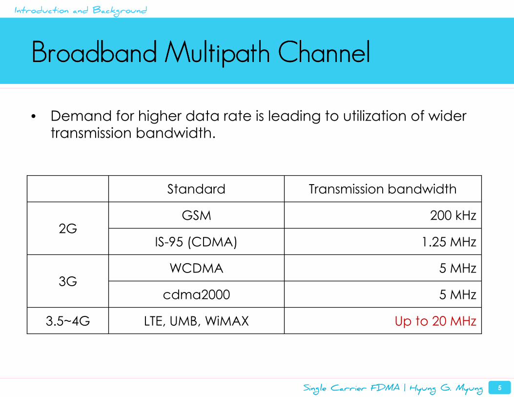
Broadband Multipath ChannelBroadband Multipath ChannelBroadband Multipath ChannelBroadband Multipath Channel
• Demand for higher data rate is leading to utilization of wider transmission bandwidth.
Up to 20 MHzLTE, UMB, WiMAX3.5~4G
5 MHzcdma2000
5 MHzWCDMA3G
1.25 MHzIS-95 (CDMA)
200 kHzGSM2G
Transmission bandwidthStandard
Introduction and Background
Single Carrier FDMA | Hyung G. Myung 6
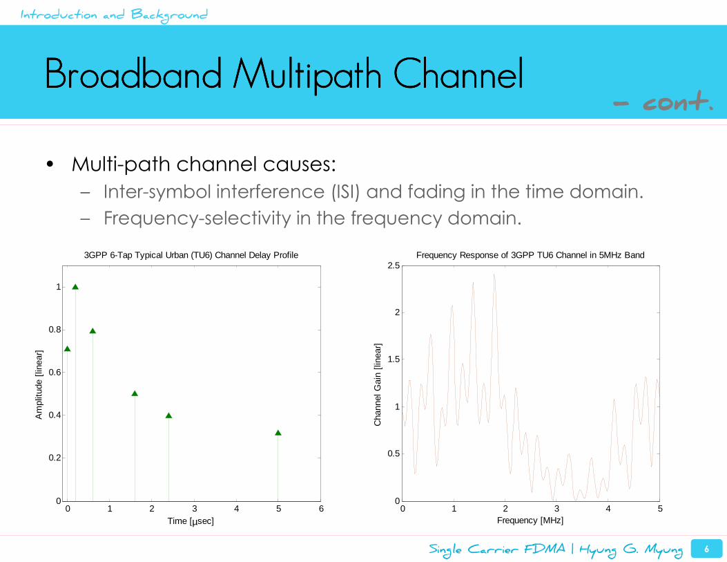
Broadband Multipath ChannelBroadband Multipath ChannelBroadband Multipath ChannelBroadband Multipath Channel
• Multi-path channel causes:
– Inter-symbol interference (ISI) and fading in the time domain.
– Frequency-selectivity in the frequency domain.
0 1 2 3 4 5 60
0.2
0.4
0.6
0.8
1
Time [µsec]
Am
plitu
de [
linea
r]
3GPP 6-Tap Typical Urban (TU6) Channel Delay Profile
0 1 2 3 4 50
0.5
1
1.5
2
2.5
Frequency [MHz]
Cha
nnel
Gai
n [li
near
]
Frequency Response of 3GPP TU6 Channel in 5MHz Band
Introduction and Background
- cont.
Single Carrier FDMA | Hyung G. Myung 7
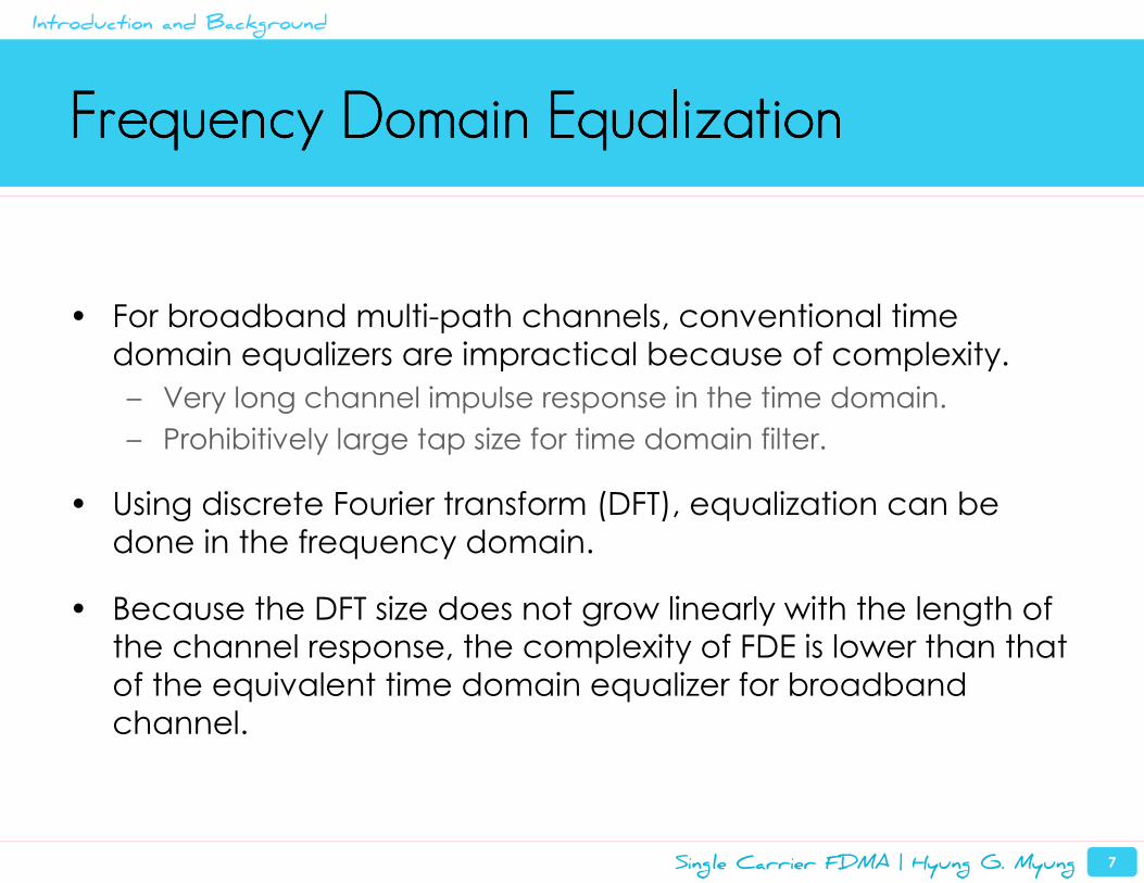
Frequency Domain EqualizationFrequency Domain EqualizationFrequency Domain EqualizationFrequency Domain Equalization
• For broadband multi-path channels, conventional time
domain equalizers are impractical because of complexity.
– Very long channel impulse response in the time domain.
– Prohibitively large tap size for time domain filter.
• Using discrete Fourier transform (DFT), equalization can be
done in the frequency domain.
• Because the DFT size does not grow linearly with the length of the channel response, the complexity of FDE is lower than that
of the equivalent time domain equalizer for broadband
channel.
Introduction and Background
Single Carrier FDMA | Hyung G. Myung 8
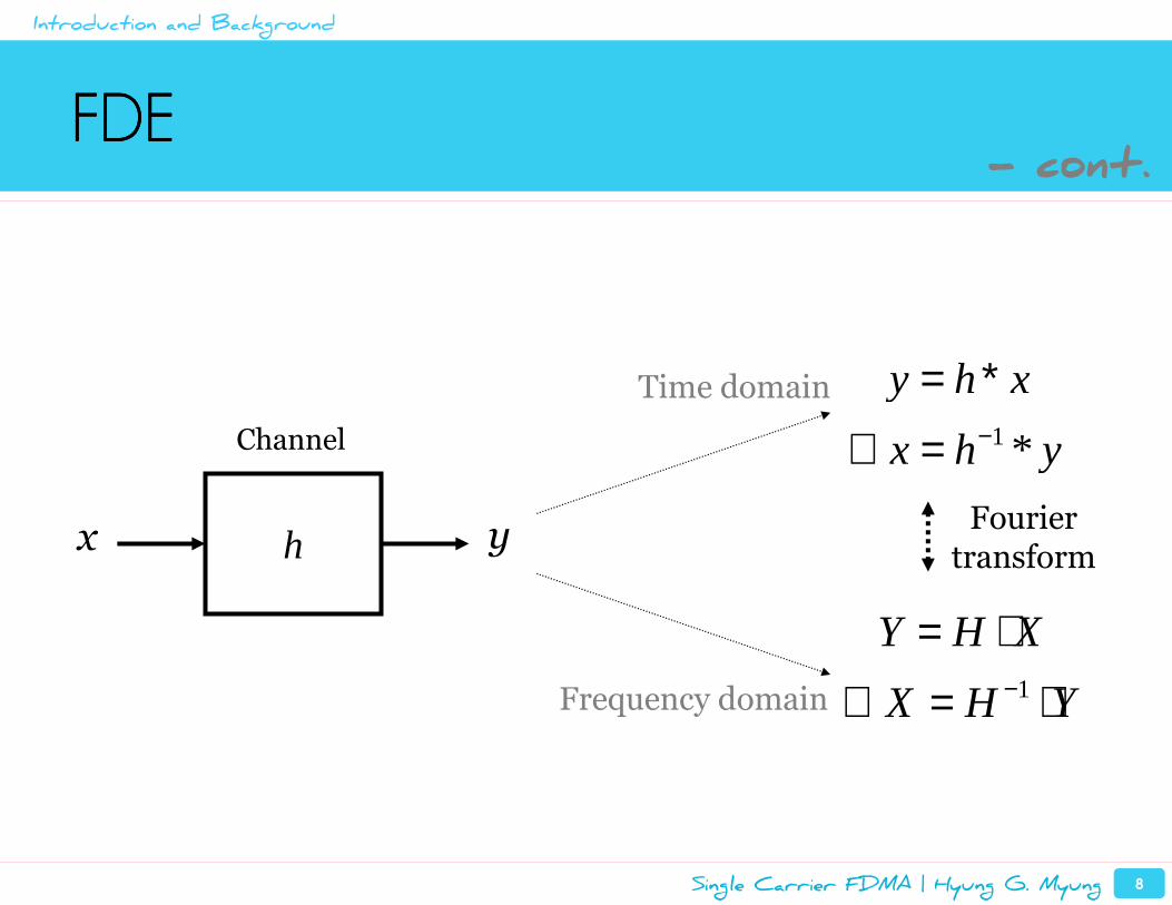
FDEFDEFDEFDE
hx y
1 *
y h x
x h y−
= ∗∴ =
1
Y H X
X H Y−
= ⋅∴ = ⋅
Time domain
Frequency domain
Fouriertransform
Channel
- cont.
Introduction and Background
Single Carrier FDMA | Hyung G. Myung 9
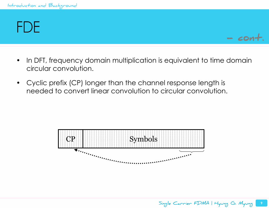
• In DFT, frequency domain multiplication is equivalent to time domain
circular convolution.
• Cyclic prefix (CP) longer than the channel response length is
needed to convert linear convolution to circular convolution.
FDEFDEFDEFDE
CP Symbols
- cont.
Introduction and Background
Single Carrier FDMA | Hyung G. Myung 10
FDEFDEFDEFDE
• Most of the time domain equalization techniques can be
implemented in the frequency domain.
– MMSE equalizer, DFE, turbo equalizer, and so on.
• References
– M. V. Clark, “Adaptive Frequency-Domain Equalization and
Diversity Combining for Broadband Wireless Communications,”
IEEE J. Sel. Areas Commun., vol. 16, no. 8, Oct. 1998
– M. Tüchler et al., “Linear Time and Frequency Domain Turbo
Equalization,” Proc. IEEE 53rd Veh. Technol. Conf. (VTC), vol. 2,
May 2001
– F. Pancaldi et al., “Block Channel Equalization in the Frequency
Domain,” IEEE Trans. Commun., vol. 53, no. 3, Mar. 2005
- cont.
Introduction and Background
Single Carrier FDMA | Hyung G. Myung 11
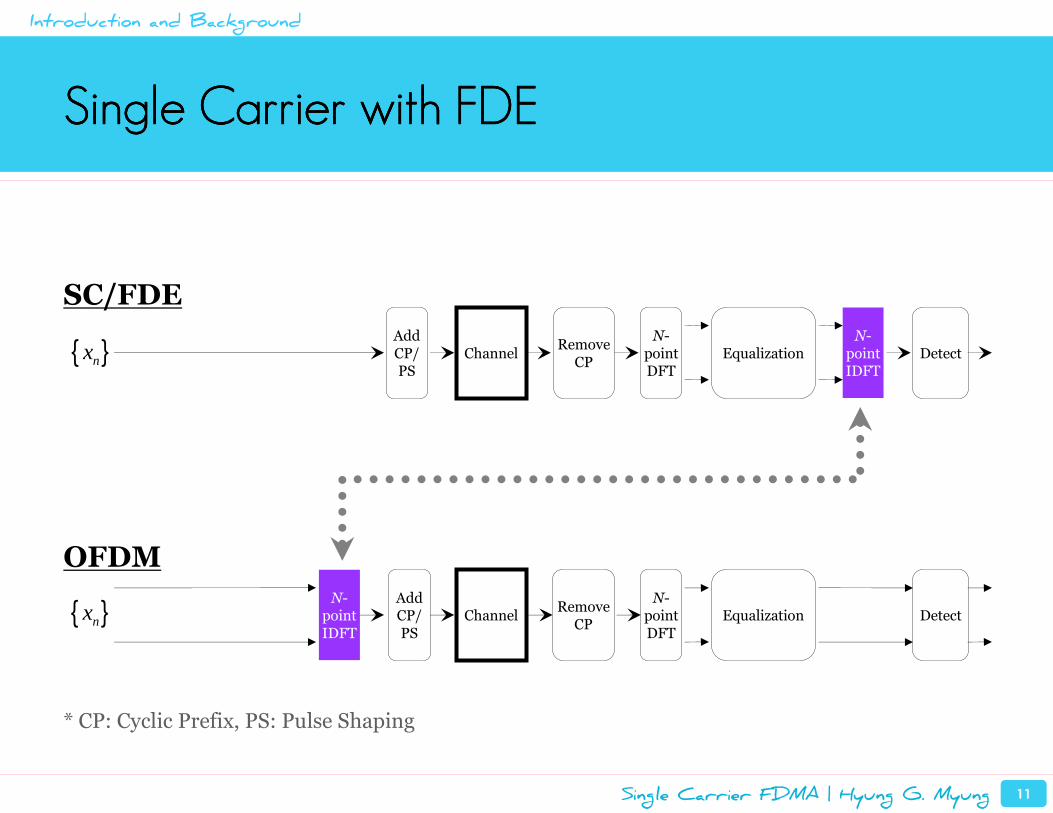
Single Carrier with FDESingle Carrier with FDESingle Carrier with FDESingle Carrier with FDE
ChannelN-
point IDFT
EqualizationN-
pointDFT
SC/FDE
OFDM
DetectRemove
CP{ }nxAdd CP/ PS
* CP: Cyclic Prefix, PS: Pulse Shaping
Channel EqualizationN-
pointDFT
DetectRemove
CP
N-point IDFT
Add CP/ PS
{ }nx
Introduction and Background
Single Carrier FDMA | Hyung G. Myung 12
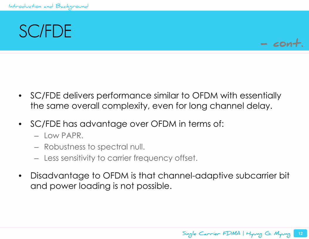
SC/FDESC/FDESC/FDESC/FDE
• SC/FDE delivers performance similar to OFDM with essentially the same overall complexity, even for long channel delay.
• SC/FDE has advantage over OFDM in terms of:
– Low PAPR.
– Robustness to spectral null.
– Less sensitivity to carrier frequency offset.
• Disadvantage to OFDM is that channel-adaptive subcarrier bit
and power loading is not possible.
- cont.
Introduction and Background
Single Carrier FDMA | Hyung G. Myung 13
SC/FDESC/FDESC/FDESC/FDE
• References
– H. Sari et al., “Transmission Techniques for Digital Terrestrial TV Broadcasting,” IEEE Commun. Mag., vol. 33, no. 2, Feb. 1995, pp. 100-109.
– D. Falconer et al., “Frequency Domain Equalization for Single-Carrier Broadband Wireless Systems,” IEEE Commun. Mag., vol. 40, no. 4, Apr. 2002, pp. 58-66.
• Single Carrier FDMA (SC-FDMA) is an extension of SC/FDE to accommodate multiple-user access.
- cont.
Introduction and Background
Single Carrier FDMA | Hyung G. Myung 14
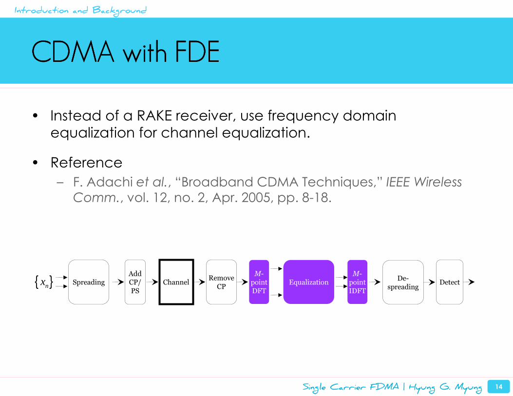
CDMA with FDECDMA with FDECDMA with FDECDMA with FDE
• Instead of a RAKE receiver, use frequency domain equalization for channel equalization.
• Reference
– F. Adachi et al., “Broadband CDMA Techniques,” IEEE Wireless
Comm., vol. 12, no. 2, Apr. 2005, pp. 8-18.
Spreading ChannelM-
point IDFT
EqualizationM-
pointDFT
DetectRemove
CP{ }nxAdd CP/ PS
De-spreading
Introduction and Background
Introduction and Background
Overview of SC-FDMA
SC-FDMA Implementation in 3GPP LTE
Peak Power Characteristics of SC-FDMA Signals
Uplink Resource Scheduling in SC-FDMA Systems
Summary and Conclusions
Single Carrier FDMA | Hyung G. Myung 16
Single Carrier FDMASingle Carrier FDMASingle Carrier FDMASingle Carrier FDMA
• SC-FDMA is a new multiple access technique.
– Utilizes single carrier modulation, DFT-spread orthogonal
frequency multiplexing, and frequency domain equalization.
• It has similar structure and performance to OFDMA.
• SC-FDMA is currently adopted as the uplink multiple access
scheme in 3GPP LTE.
– A variant of SC-FDMA using code spreading is used in 3GPP2
UMB uplink.
– 802.16m also considering it for uplink.
Overview of SC-FDMA
Single Carrier FDMA | Hyung G. Myung 17
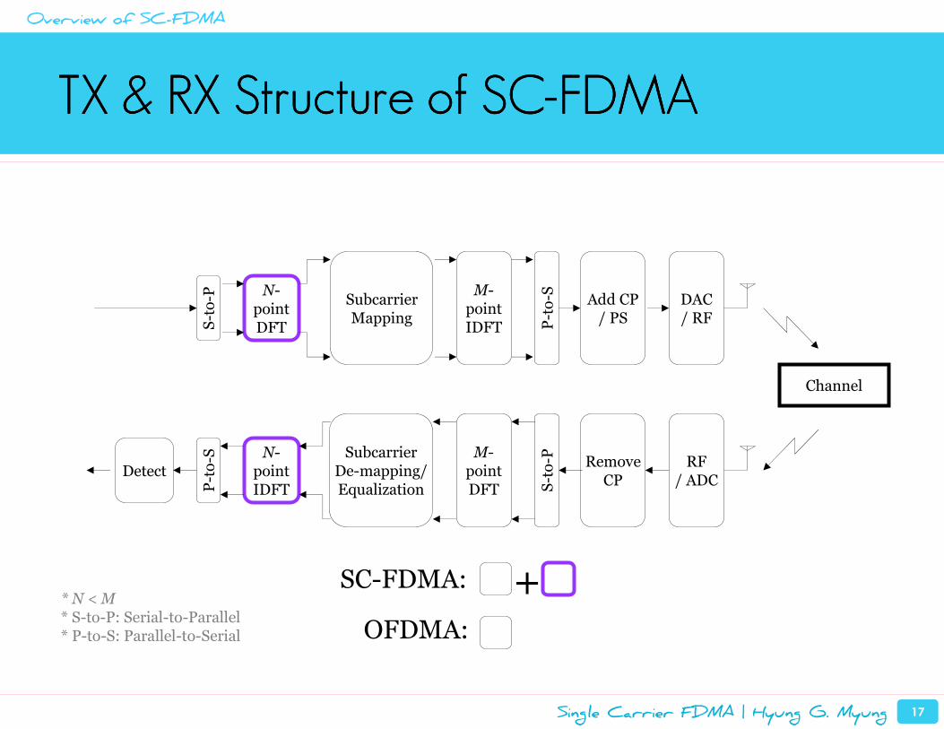
TX & RX Structure of SCTX & RX Structure of SCTX & RX Structure of SCTX & RX Structure of SC----FDMAFDMAFDMAFDMA
Subcarrier Mapping
Channel
N-point IDFT
Subcarrier De-mapping/ Equalization
M-pointDFT
DetectRemove
CP
N-point DFT
M-point IDFT
Add CP / PS
DAC/ RF
RF/ ADC
SC-FDMA:
OFDMA:
+* N < M* S-to-P: Serial-to-Parallel* P-to-S: Parallel-to-Serial
P-to-S
S-to-P
S-to-P
P-to-S
Overview of SC-FDMA
Single Carrier FDMA | Hyung G. Myung 18
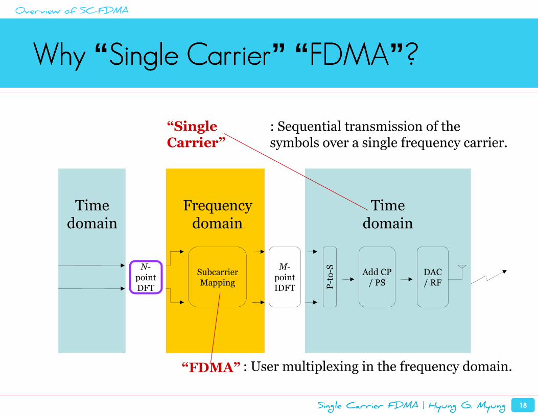
Why Why Why Why “ Single CarrierSingle CarrierSingle CarrierSingle Carrier” “ FDMAFDMAFDMAFDMA” ????
Subcarrier Mapping
N-point DFT
M-point IDFT
Add CP / PS
DAC/ RF
Timedomain
Frequencydomain
Timedomain
“FDMA”
“Single Carrier”
P-to-S
: Sequential transmission of the symbols over a single frequency carrier.
: User multiplexing in the frequency domain.
Overview of SC-FDMA
Single Carrier FDMA | Hyung G. Myung 19
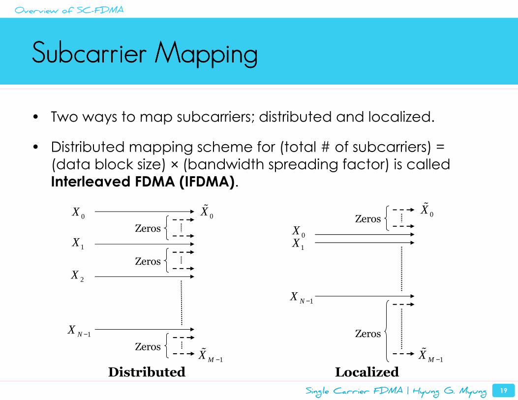
Subcarrier MappingSubcarrier MappingSubcarrier MappingSubcarrier Mapping
• Two ways to map subcarriers; distributed and localized.
• Distributed mapping scheme for (total # of subcarriers) =
(data block size) × (bandwidth spreading factor) is called Interleaved FDMA (IFDMA).
Distributed Localized
0X
1NX −
1X
Zeros
Zeros0Xɶ
1MX −ɶ
Zeros
0X
Zeros
1X
2X
1NX −
0Xɶ
1MX −ɶ
Zeros
Overview of SC-FDMA
Single Carrier FDMA | Hyung G. Myung 20
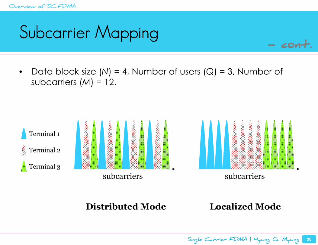
Subcarrier MappingSubcarrier MappingSubcarrier MappingSubcarrier Mapping
• Data block size (N) = 4, Number of users (Q) = 3, Number of subcarriers (M) = 12.
subcarriers
Terminal 1
Terminal 2
Terminal 3
subcarriers
Distributed Mode Localized Mode
- cont.
Overview of SC-FDMA
Single Carrier FDMA | Hyung G. Myung 21
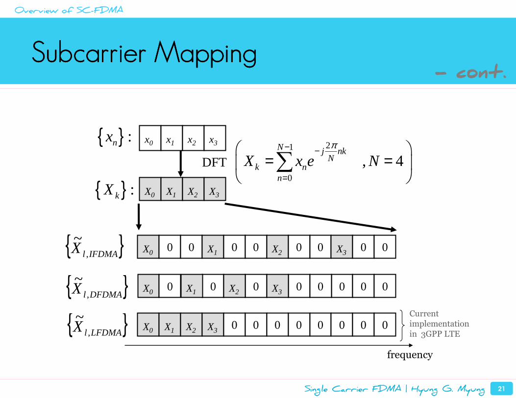
Subcarrier MappingSubcarrier MappingSubcarrier MappingSubcarrier Mapping
0 0 0 0 0 0 0 0X0 X1 X2 X3
frequency
0 0 0 0 0 0 0 0X0 X1 X2 X3
{ } :kX X0 X1 X2 X3
{ } :nx x0 x1 x2 x3
DFT
21
0
, 4N j nk
Nk n
n
X x e Nπ− −
=
= =
∑
{ }IFDMAlX ,
~
0 0 00 0 0 0 0X0 X1 X2 X3{ }DFDMAlX ,
~
{ }LFDMAlX ,
~ Current implementationin 3GPP LTE
- cont.
Overview of SC-FDMA
Single Carrier FDMA | Hyung G. Myung 22
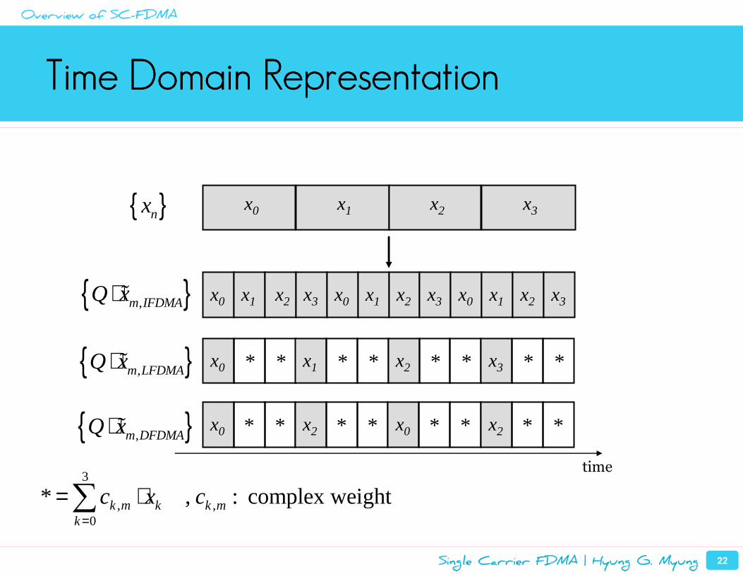
Time Domain RepresentationTime Domain RepresentationTime Domain RepresentationTime Domain Representation
x0 x1 x2 x3
x0 x1 x2 x3
{ }nx
x0 x1 x2 x3 x0 x1 x2 x3
* * * * * * * *x0 x2 x0 x2
time
* * * * * * * *x0 x1 x2 x3
{ },m IFDMAQ x⋅ ɶ
{ },m DFDMAQ x⋅ ɶ
{ },m LFDMAQ x⋅ ɶ
3
, ,0
* , : complex weightk m k k mk
c x c=
= ⋅∑
Overview of SC-FDMA
Single Carrier FDMA | Hyung G. Myung 23
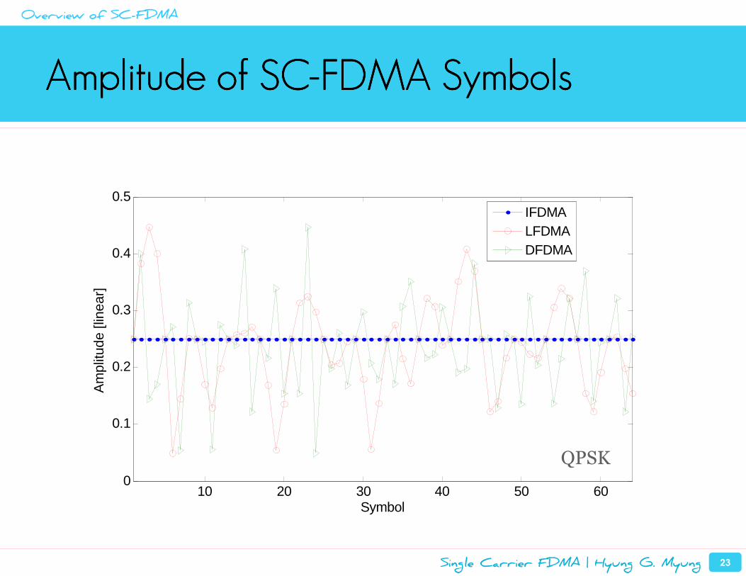
Amplitude of SCAmplitude of SCAmplitude of SCAmplitude of SC----FDMA SymbolsFDMA SymbolsFDMA SymbolsFDMA Symbols
10 20 30 40 50 600
0.1
0.2
0.3
0.4
0.5
Symbol
Am
plitu
de [l
inea
r]
IFDMALFDMADFDMA
QPSK
Overview of SC-FDMA
Single Carrier FDMA | Hyung G. Myung 24
SCSCSCSC----FDMA and OFDMA FDMA and OFDMA FDMA and OFDMA FDMA and OFDMA
• Similarities
– Block-based modulation and use of CP.
– Divides the transmission bandwidth into smaller subcarriers.
– Channel inversion/equalization is done in the frequency domain.
– SC-FDMA is regarded as DFT-precoded or DFT-spread OFDMA.
Overview of SC-FDMA
Single Carrier FDMA | Hyung G. Myung 25
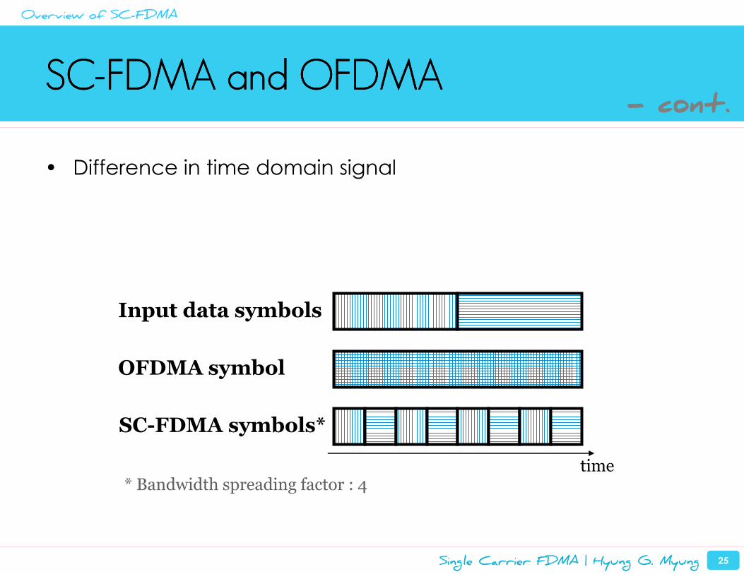
SCSCSCSC----FDMA and OFDMA FDMA and OFDMA FDMA and OFDMA FDMA and OFDMA
• Difference in time domain signal
OFDMA symbol
SC-FDMA symbols*
Input data symbols
* Bandwidth spreading factor : 4time
- cont.
Overview of SC-FDMA
Single Carrier FDMA | Hyung G. Myung 26
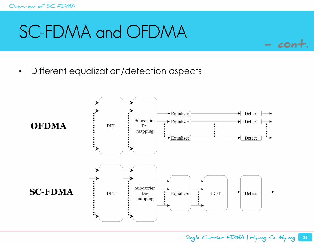
SCSCSCSC----FDMA and OFDMA FDMA and OFDMA FDMA and OFDMA FDMA and OFDMA
• Different equalization/detection aspects
Subcarrier De-
mapping
Equalizer
Equalizer
Equalizer
Subcarrier De-
mapping
Detect
Detect
Detect
Equalizer IDFT DetectSC-FDMA
OFDMA DFT
DFT
- cont.
Overview of SC-FDMA
Single Carrier FDMA | Hyung G. Myung 27
SCSCSCSC----FDMA and DSFDMA and DSFDMA and DSFDMA and DS----CDMACDMACDMACDMA
• In terms of bandwidth expansion, SC-FDMA is very similar to
DS-CDMA system using orthogonal spreading codes.
– Both spread narrowband data into broader band.
– Time symbols are compressed into “chips” after modulation.– Spreading gain (processing gain) is achieved.
Overview of SC-FDMA
Single Carrier FDMA | Hyung G. Myung 28
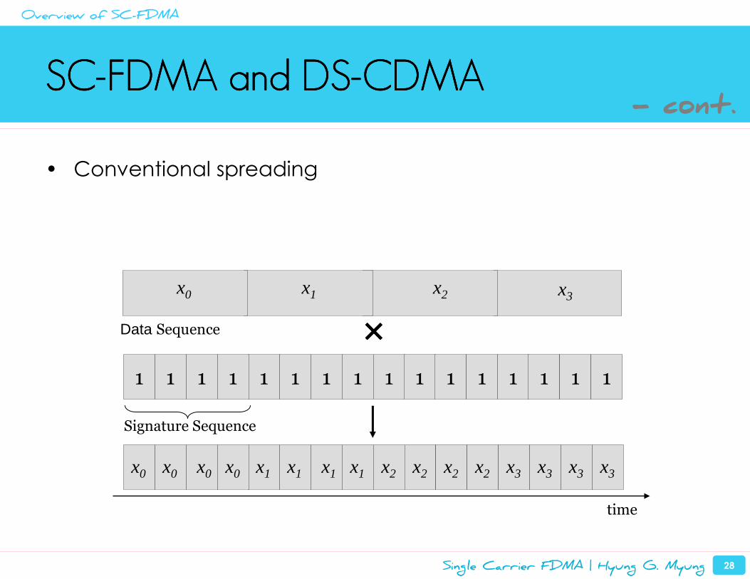
SCSCSCSC----FDMA and DSFDMA and DSFDMA and DSFDMA and DS----CDMACDMACDMACDMA
• Conventional spreading
x1 x2 x3
1 1 1
x1 x1 x1 x1 x2 x2 x2 x2 x3 x3 x3 x3
1 1 1 1 1 1 1 1 1
Signature Sequence
Data Sequence ××××
time
x0 x0 x0 x0
1 1 1 1
x0
- cont.
Overview of SC-FDMA
Single Carrier FDMA | Hyung G. Myung 29
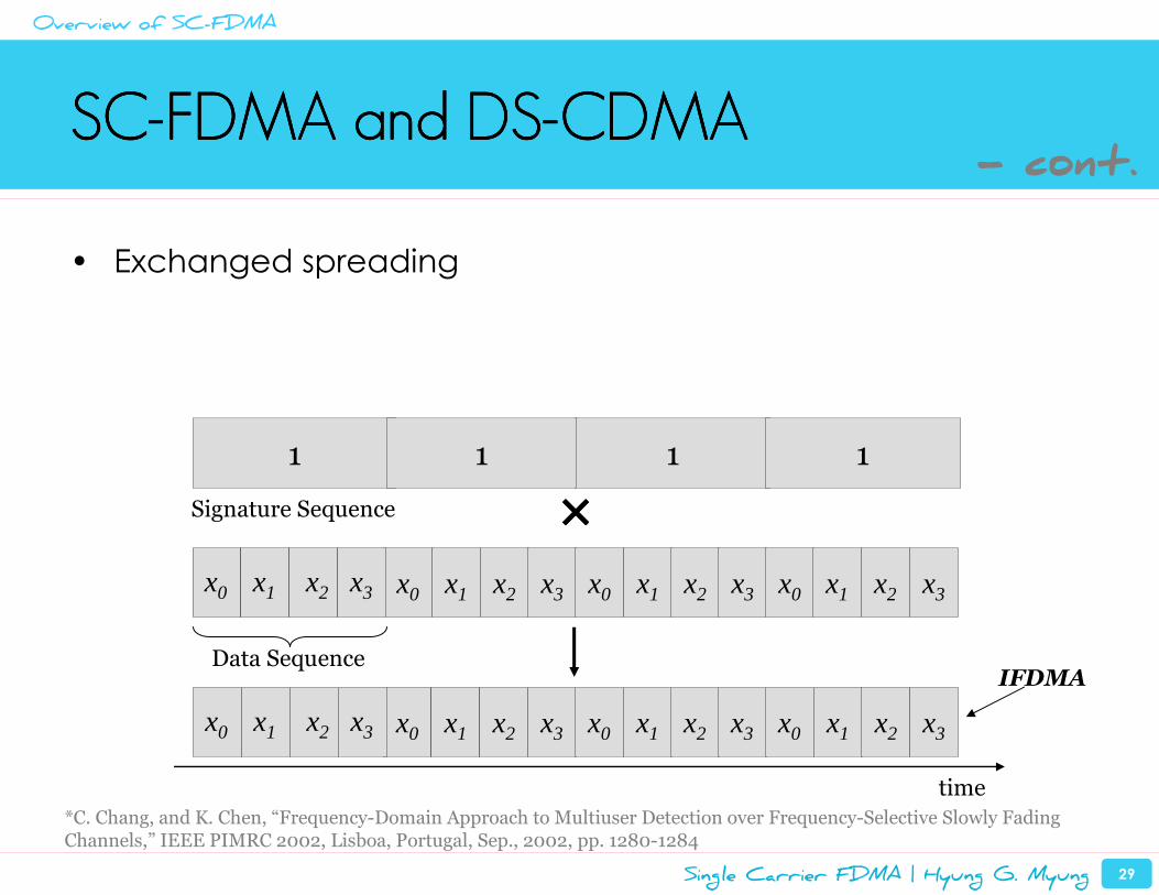
SCSCSCSC----FDMA and DSFDMA and DSFDMA and DSFDMA and DS----CDMACDMACDMACDMA
• Exchanged spreading
time
1
x0 x1 x2 x3
1 1
x0 x1 x2 x3 x0 x1 x2 x3
x0 x1 x2 x3 x0 x1 x2 x3 x0 x1 x2 x3
××××
Data Sequence
Signature Sequence
x0 x1 x2 x3
x0 x1 x2 x3
1
IFDMA
- cont.
Overview of SC-FDMA
*C. Chang, and K. Chen, “Frequency-Domain Approach to Multiuser Detection over Frequency-Selective Slowly Fading Channels,” IEEE PIMRC 2002, Lisboa, Portugal, Sep., 2002, pp. 1280-1284
Single Carrier FDMA | Hyung G. Myung 30
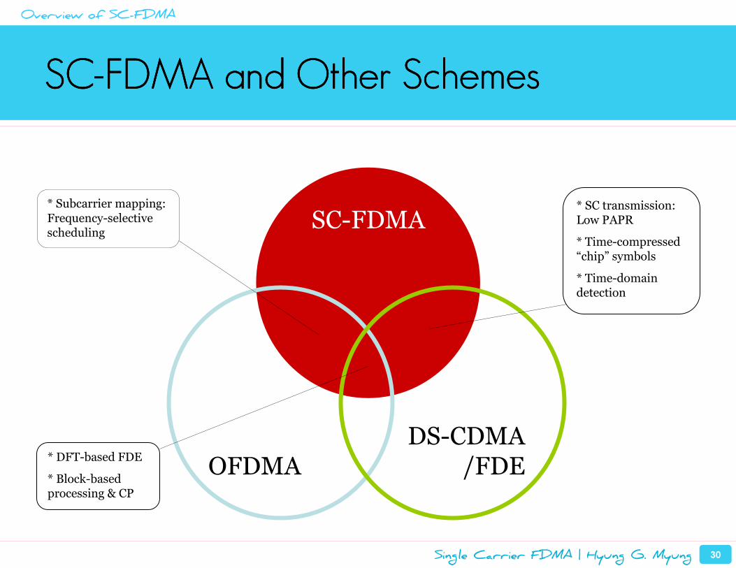
SCSCSCSC----FDMA and Other SchemesFDMA and Other SchemesFDMA and Other SchemesFDMA and Other Schemes
SC-FDMA
OFDMADS-CDMA
/FDE* DFT-based FDE
* Block-based processing & CP
* SC transmission: Low PAPR
* Time-compressed “chip” symbols
* Time-domain detection
* Subcarrier mapping: Frequency-selective scheduling
Overview of SC-FDMA
Single Carrier FDMA | Hyung G. Myung 31
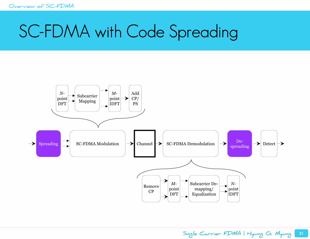
SCSCSCSC----FDMA with Code SpreadingFDMA with Code SpreadingFDMA with Code SpreadingFDMA with Code Spreading
Subcarrier Mapping
Channel
N-point IDFT
Subcarrier De-mapping/
Equalization
M-pointDFT
Detect
Remove CP
N-point DFT
M-point IDFT
Add CP/ PS
SpreadingDe-
spreadingSC-FDMA Modulation SC-FDMA Demodulation
Overview of SC-FDMA
Single Carrier FDMA | Hyung G. Myung 32
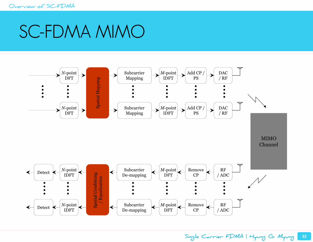
SCSCSCSC----FDMA MIMOFDMA MIMOFDMA MIMOFDMA MIMO
Subcarrier Mapping
MIMOChannel
N-point IDFT
Subcarrier De-mapping
M-pointDFT
DetectRemove
CP
N-point DFT
M-point IDFT
Add CP / PS
DAC/ RF
RF/ ADC
Spatial Mapping
Subcarrier Mapping
N-point DFT
M-point IDFT
Add CP / PS
DAC/ RF
Spatial Combining
/ Equalization
N-point IDFT
Subcarrier De-mapping
M-pointDFT
DetectRemove
CPRF
/ ADC
Overview of SC-FDMA
Introduction and Background
Overview of SC-FDMA
SC-FDMA Implementation in 3GPP LTE
Peak Power Characteristics of SC-FDMA Signals
Uplink Resource Scheduling in SC-FDMA Systems
Summary and Conclusions
Single Carrier FDMA | Hyung G. Myung 34
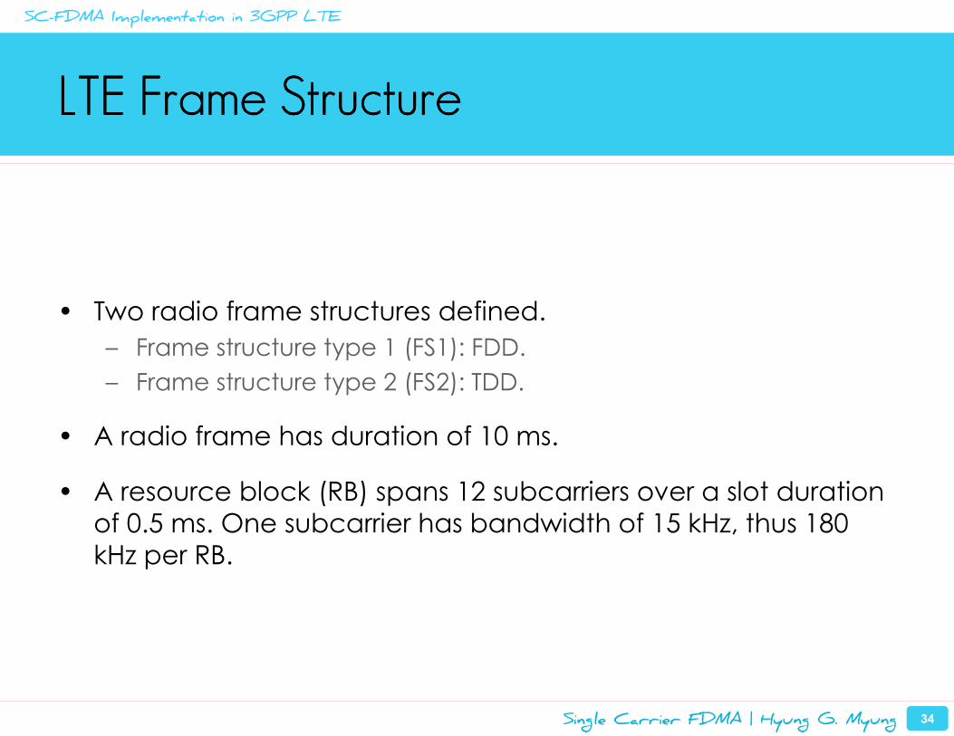
LTE Frame StructureLTE Frame StructureLTE Frame StructureLTE Frame Structure
• Two radio frame structures defined.
– Frame structure type 1 (FS1): FDD.
– Frame structure type 2 (FS2): TDD.
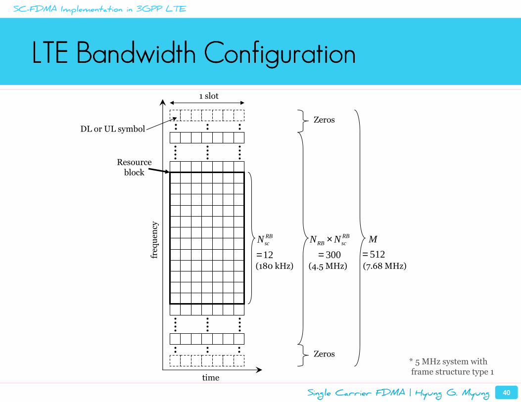
• A radio frame has duration of 10 ms.
• A resource block (RB) spans 12 subcarriers over a slot duration
of 0.5 ms. One subcarrier has bandwidth of 15 kHz, thus 180
kHz per RB.
SC-FDMA Implementation in 3GPP LTE
Single Carrier FDMA | Hyung G. Myung 35
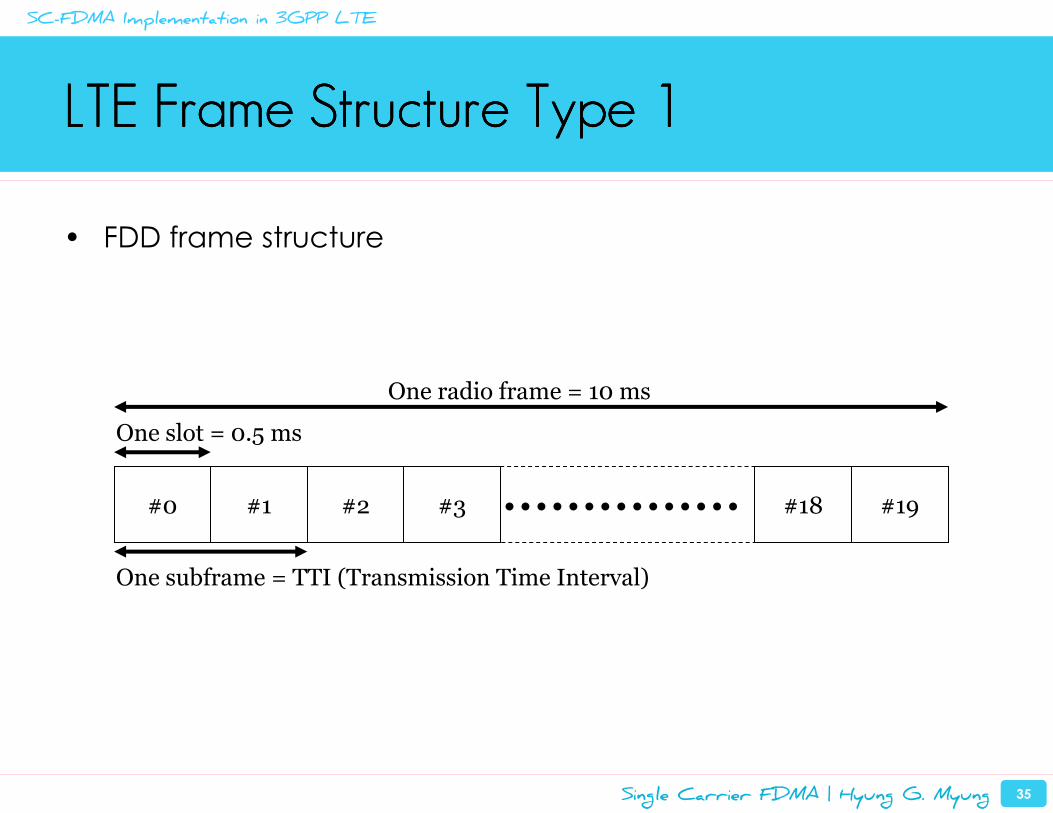
LTE Frame Structure Type 1LTE Frame Structure Type 1LTE Frame Structure Type 1LTE Frame Structure Type 1
• FDD frame structure
One subframe = TTI (Transmission Time Interval)
#0 #1 #2 #3 #18 #19
One slot = 0.5 ms
One radio frame = 10 ms
SC-FDMA Implementation in 3GPP LTE
Single Carrier FDMA | Hyung G. Myung 36
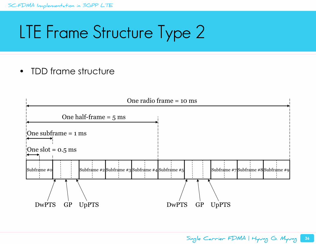
LTE Frame Structure Type 2LTE Frame Structure Type 2LTE Frame Structure Type 2LTE Frame Structure Type 2
• TDD frame structure
Subframe #0 Subframe #2 Subframe #3 Subframe #4 Subframe #5 Subframe #7 Subframe #8 Subframe #9
DwPTS GP UpPTS DwPTS GP UpPTS
One subframe = 1 ms
One half-frame = 5 ms
One radio frame = 10 ms
One slot = 0.5 ms
SC-FDMA Implementation in 3GPP LTE
Single Carrier FDMA | Hyung G. Myung 37
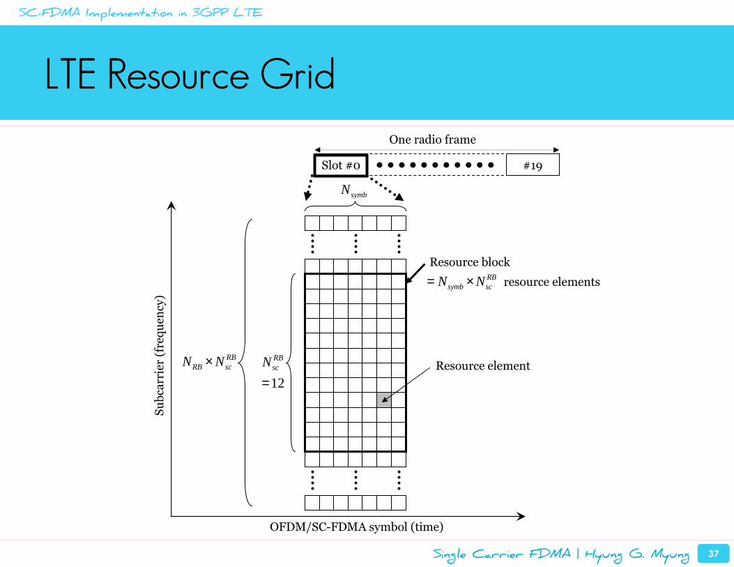
LTE Resource GridLTE Resource GridLTE Resource GridLTE Resource Grid
Slot #0 #19
One radio frame
Subcarrier (frequen
cy)
OFDM/SC-FDMA symbol (time)
RBRB scN N×
12
RBscN
=
symbN
Resource block
Resource element
RBsymb scN N= × resource elements
SC-FDMA Implementation in 3GPP LTE
Single Carrier FDMA | Hyung G. Myung 38
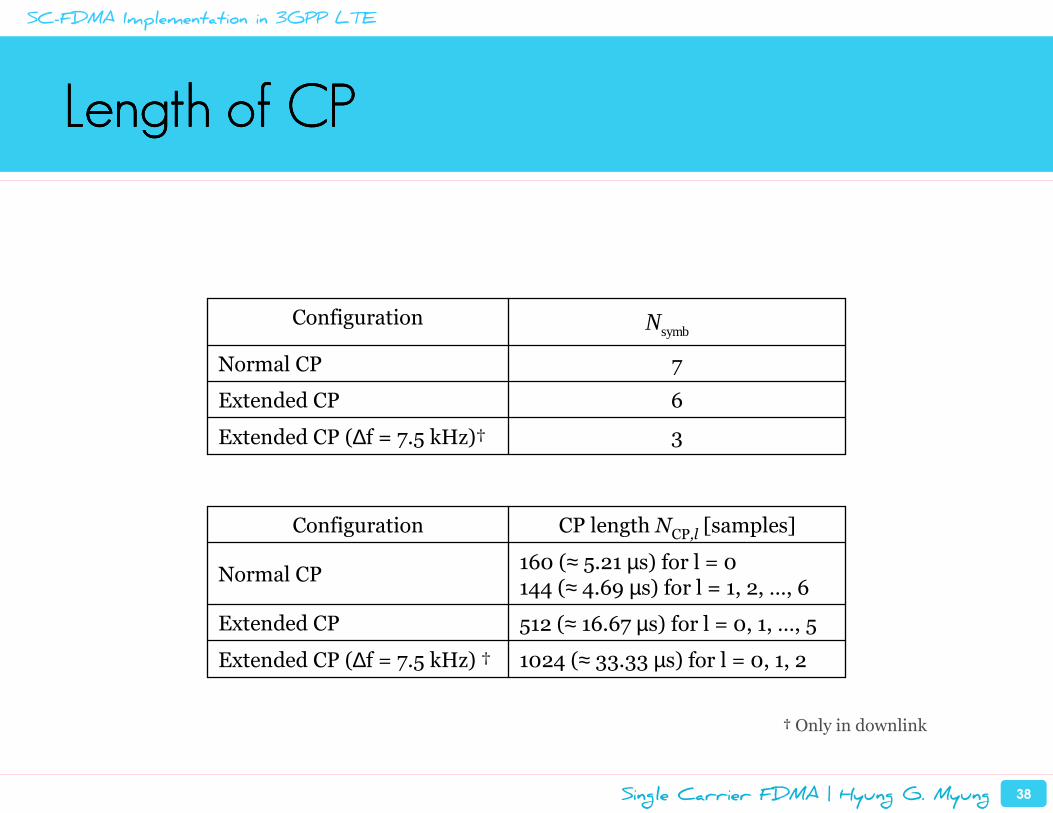
Length of CPLength of CPLength of CPLength of CP
symbN
6Extended CP
3Extended CP (∆f = 7.5 kHz)†
7Normal CP
Configuration
512 (≈ 16.67 µs) for l = 0, 1, …, 5Extended CP
1024 (≈ 33.33 µs) for l = 0, 1, 2Extended CP (∆f = 7.5 kHz) †
160 (≈ 5.21 µs) for l = 0144 (≈ 4.69 µs) for l = 1, 2, …, 6
Normal CP
CP length NCP,l [samples]Configuration
† Only in downlink
SC-FDMA Implementation in 3GPP LTE
Single Carrier FDMA | Hyung G. Myung 39
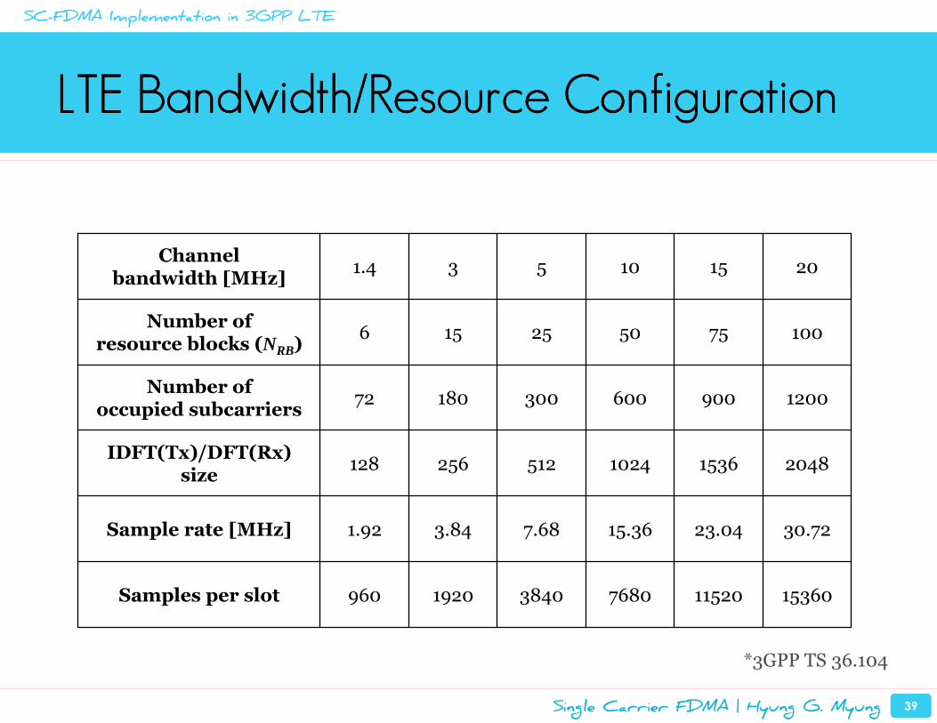
LTE Bandwidth/Resource ConfigurationLTE Bandwidth/Resource ConfigurationLTE Bandwidth/Resource ConfigurationLTE Bandwidth/Resource Configuration
1536011520768038401920960Samples per slot
30.7223.0415.367.683.841.92Sample rate [MHz]
204815361024512256128IDFT(Tx)/DFT(Rx)
size
120090060030018072Number of
occupied subcarriers
100755025156Number of
resource blocks (NRB)
201510531.4Channel
bandwidth [MHz]
*3GPP TS 36.104
SC-FDMA Implementation in 3GPP LTE
Single Carrier FDMA | Hyung G. Myung 40
LTE Bandwidth ConfigurationLTE Bandwidth ConfigurationLTE Bandwidth ConfigurationLTE Bandwidth Configuration
frequen
cy
time
300
RBRB scN N×=12
RBscN
=(7.68 MHz)
512
M
=(4.5 MHz)(180 kHz)
Resourceblock
Zeros
Zeros
1 slot
DL or UL symbol
* 5 MHz system withframe structure type 1
SC-FDMA Implementation in 3GPP LTE
Single Carrier FDMA | Hyung G. Myung 41
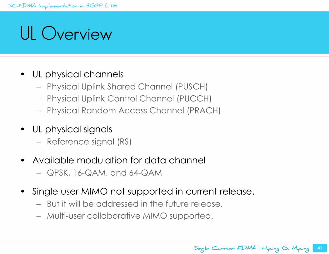
UL Overview UL Overview UL Overview UL Overview
• UL physical channels
– Physical Uplink Shared Channel (PUSCH)
– Physical Uplink Control Channel (PUCCH)
– Physical Random Access Channel (PRACH)
• UL physical signals
– Reference signal (RS)
• Available modulation for data channel
– QPSK, 16-QAM, and 64-QAM
• Single user MIMO not supported in current release.
– But it will be addressed in the future release.
– Multi-user collaborative MIMO supported.
SC-FDMA Implementation in 3GPP LTE
Single Carrier FDMA | Hyung G. Myung 42
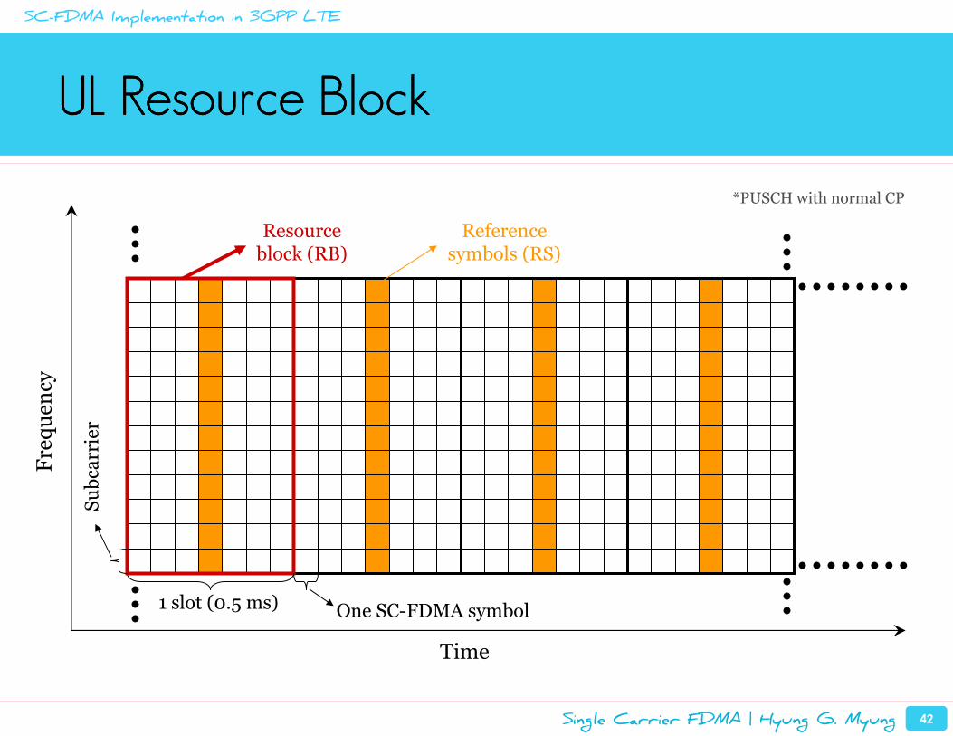
UL Resource BlockUL Resource BlockUL Resource BlockUL Resource Block
1 slot (0.5 ms)
Resourceblock (RB)
Frequency
Time
One SC-FDMA symbol
Subcarrier
Referencesymbols (RS)
*PUSCH with normal CP
SC-FDMA Implementation in 3GPP LTE
Single Carrier FDMA | Hyung G. Myung 43
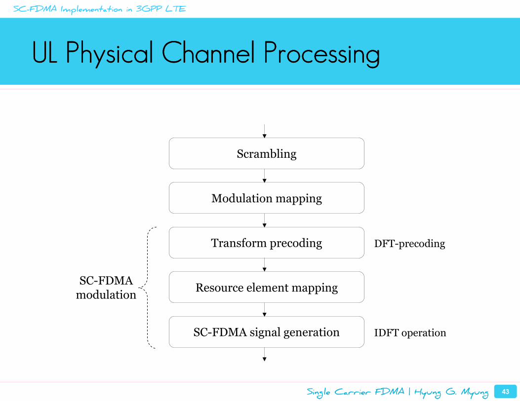
UL Physical Channel ProcessingUL Physical Channel ProcessingUL Physical Channel ProcessingUL Physical Channel Processing
Scrambling
Modulation mapping
Transform precoding
SC-FDMA signal generation
Resource element mappingSC-FDMAmodulation
DFT-precoding
IDFT operation
SC-FDMA Implementation in 3GPP LTE
Single Carrier FDMA | Hyung G. Myung 44
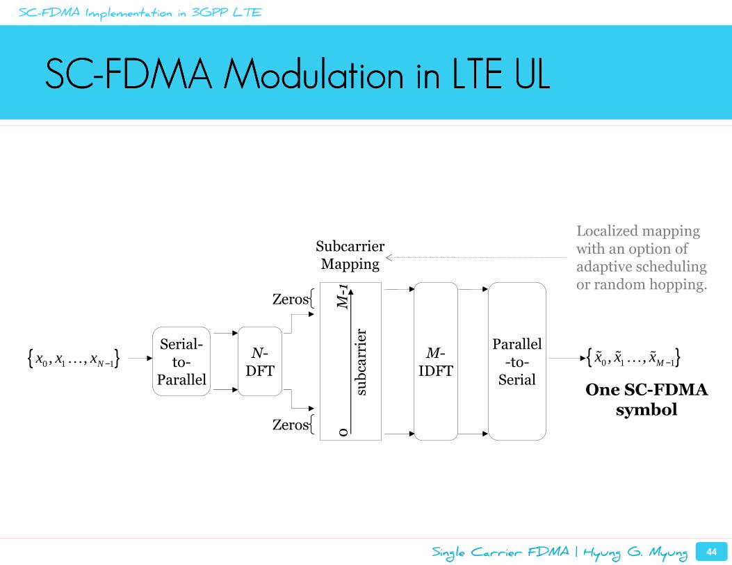
SCSCSCSC----FDMA Modulation in LTE ULFDMA Modulation in LTE ULFDMA Modulation in LTE ULFDMA Modulation in LTE UL
Serial-to-
Parallel
M-IDFT
N-DFT
Zeros
{ }0 1 1, , Nx x x −…
Parallel-to-Serial
{ }0 1 1, , Mx x x −ɶ ɶ ɶ…
Subcarrier Mapping
subcarrier
0M-1
Zeros
One SC-FDMA symbol
Localized mapping with an option of adaptive scheduling or random hopping.
SC-FDMA Implementation in 3GPP LTE
Single Carrier FDMA | Hyung G. Myung 45
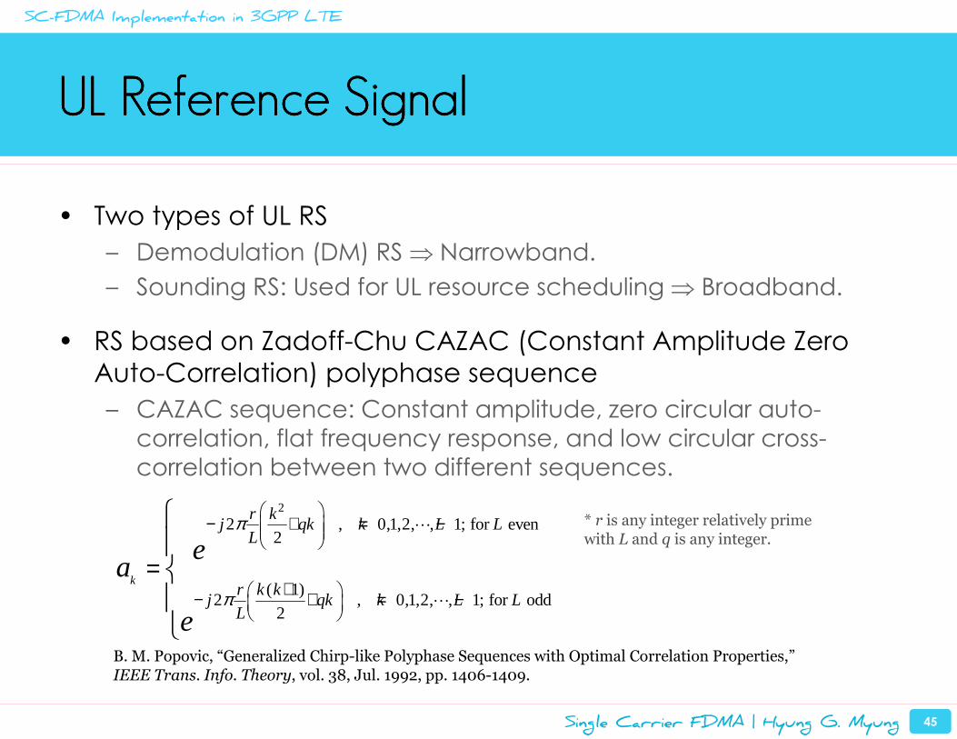
UL Reference SignalUL Reference SignalUL Reference SignalUL Reference Signal
• Two types of UL RS
– Demodulation (DM) RS ⇒ Narrowband.
– Sounding RS: Used for UL resource scheduling ⇒ Broadband.
• RS based on Zadoff-Chu CAZAC (Constant Amplitude Zero
Auto-Correlation) polyphase sequence
– CAZAC sequence: Constant amplitude, zero circular auto-
correlation, flat frequency response, and low circular cross-
correlation between two different sequences.
2
2 , 0,1,2, , 1; for even2
( 1)2 , 0,1,2, , 1; for odd
2
k
r kj qk k L L
L
r k kj qk k L L
L
ea
e
π
π
− + = −
+ − + = −
=
⋯
⋯
* r is any integer relatively prime with L and q is any integer.
B. M. Popovic, “Generalized Chirp-like Polyphase Sequences with Optimal Correlation Properties,”IEEE Trans. Info. Theory, vol. 38, Jul. 1992, pp. 1406-1409.
SC-FDMA Implementation in 3GPP LTE
Single Carrier FDMA | Hyung G. Myung 46
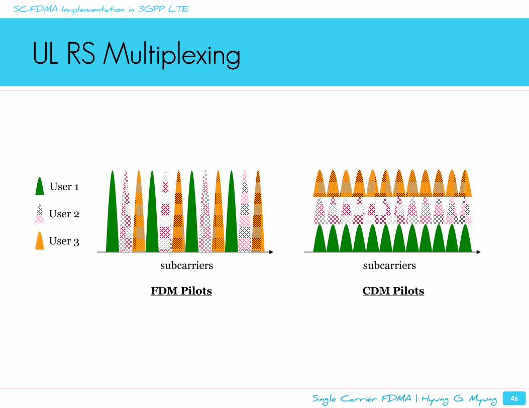
UL RS MultiplexingUL RS MultiplexingUL RS MultiplexingUL RS Multiplexing
subcarriers
User 1
User 2
User 3
subcarriers
FDM Pilots CDM Pilots
SC-FDMA Implementation in 3GPP LTE
Single Carrier FDMA | Hyung G. Myung 47
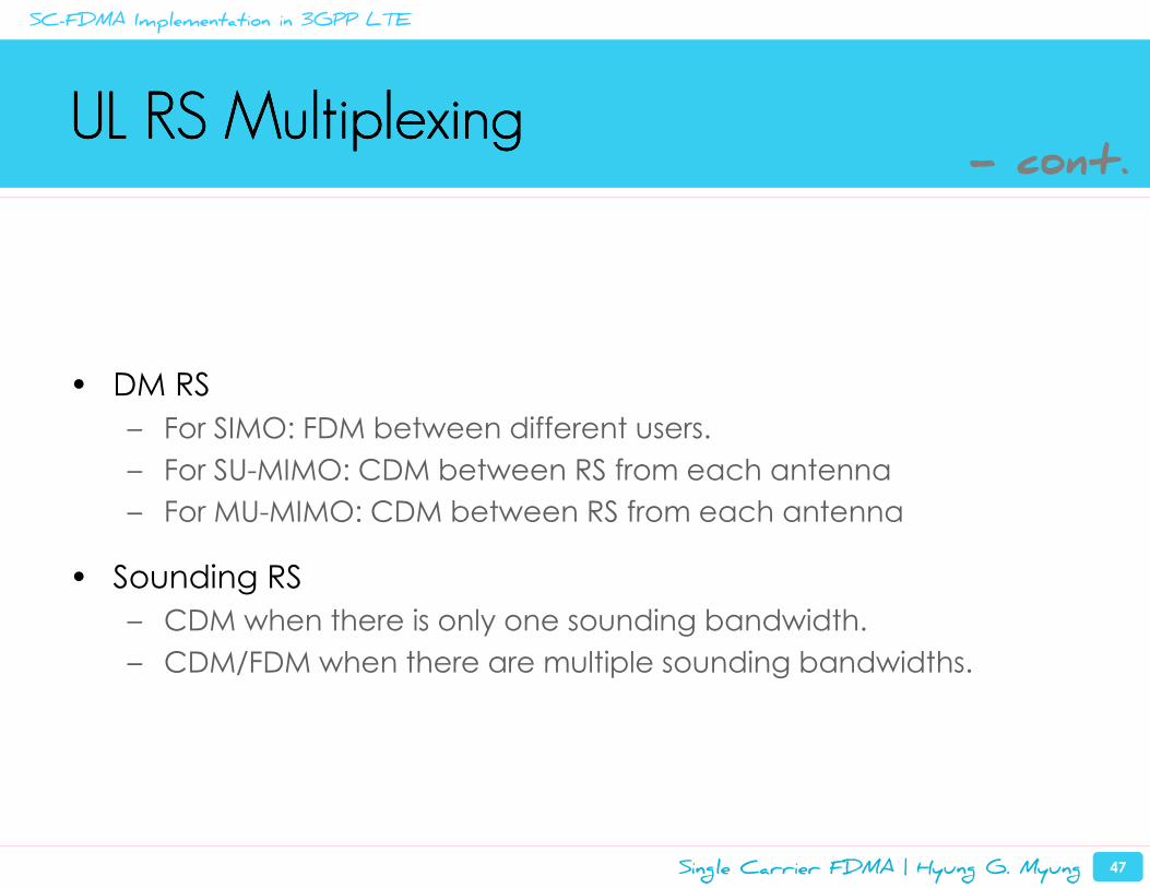
UL RS MultiplexingUL RS MultiplexingUL RS MultiplexingUL RS Multiplexing
• DM RS
– For SIMO: FDM between different users.
– For SU-MIMO: CDM between RS from each antenna
– For MU-MIMO: CDM between RS from each antenna
• Sounding RS
– CDM when there is only one sounding bandwidth.
– CDM/FDM when there are multiple sounding bandwidths.
- cont.
SC-FDMA Implementation in 3GPP LTE
Introduction and Background
Overview of SC-FDMA
SC-FDMA Implementation in 3GPP LTE
Peak Power Characteristics of SC-FDMA Signals
Uplink Resource Scheduling in SC-FDMA Systems
Summary and Conclusions
Single Carrier FDMA | Hyung G. Myung 49
0 2 4 6 8 10 1210
-4
10-3
10-2
10-1
100
Pr(
PA
PR
>P
AP
R0)
PAPR0 [dB]
CCDF of PAPR: 16-QAM, Rolloff = 0.22, Nfft
= 512, Noccupied
= 128
Dotted lines: no PSDashed lines: RRC PSSolid lines: RC PS
IFDMA
DFDMA
LFDMA
OFDMA
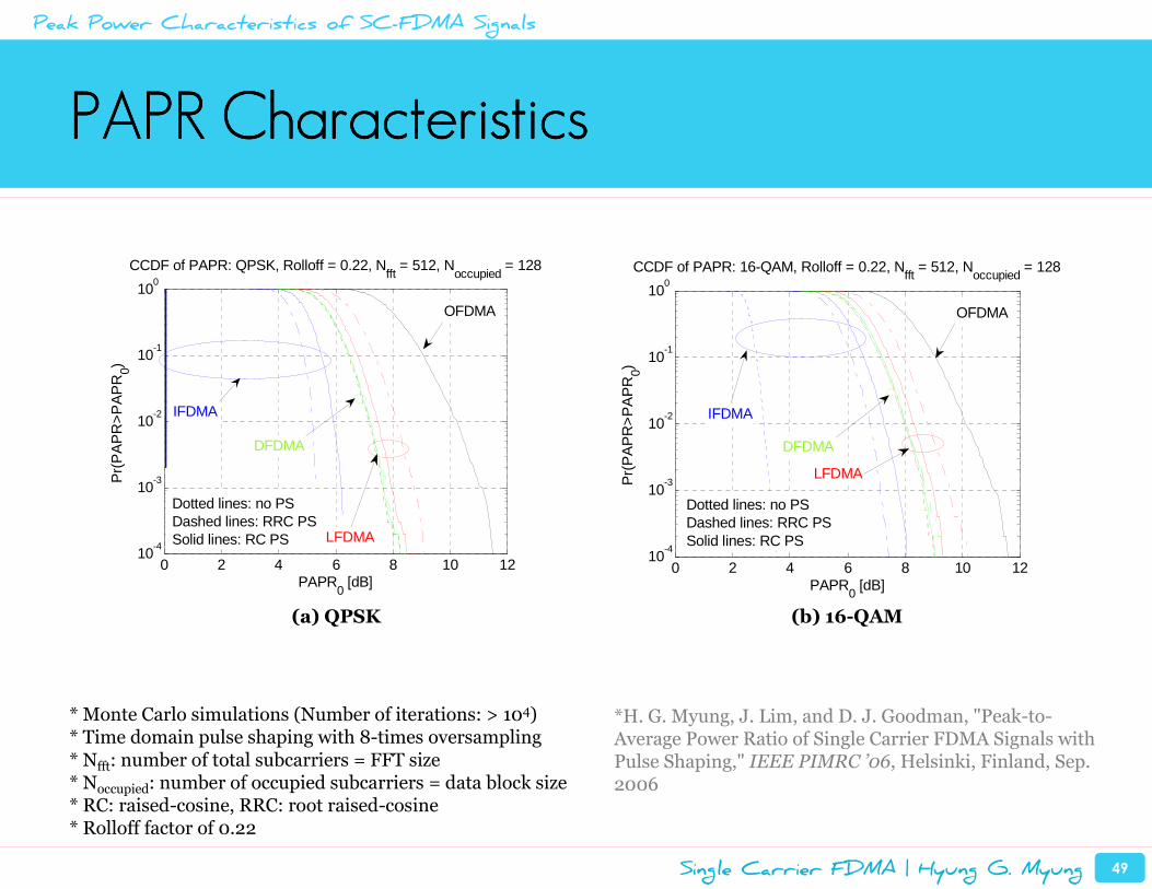
PAPR CharacteristicsPAPR CharacteristicsPAPR CharacteristicsPAPR Characteristics
* Monte Carlo simulations (Number of iterations: > 104)* Time domain pulse shaping with 8-times oversampling* Nfft: number of total subcarriers = FFT size* Noccupied: number of occupied subcarriers = data block size* RC: raised-cosine, RRC: root raised-cosine* Rolloff factor of 0.22
Peak Power Characteristics of SC-FDMA Signals
(a) QPSK (b) 16-QAM
0 2 4 6 8 10 1210
-4
10-3
10-2
10-1
100
Pr(
PA
PR
>P
AP
R0)
PAPR0 [dB]
CCDF of PAPR: QPSK, Rolloff = 0.22, Nfft
= 512, Noccupied
= 128
Dotted lines: no PSDashed lines: RRC PSSolid lines: RC PS
IFDMA
DFDMA
LFDMA
OFDMA
*H. G. Myung, J. Lim, and D. J. Goodman, "Peak-to-Average Power Ratio of Single Carrier FDMA Signals with Pulse Shaping," IEEE PIMRC ’06, Helsinki, Finland, Sep. 2006
Single Carrier FDMA | Hyung G. Myung 50
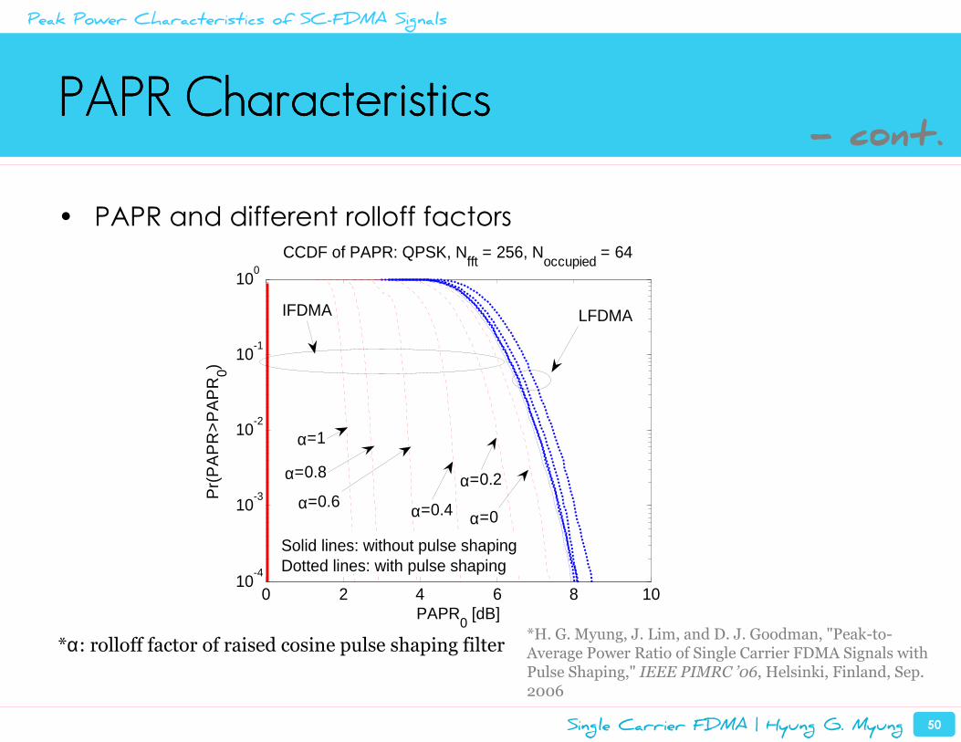
PAPR CharacteristicsPAPR CharacteristicsPAPR CharacteristicsPAPR Characteristics
• PAPR and different rolloff factors
*α: rolloff factor of raised cosine pulse shaping filter
0 2 4 6 8 1010
-4
10-3
10-2
10-1
100
Pr(
PA
PR
>P
AP
R0)
PAPR0 [dB]
CCDF of PAPR: QPSK, Nfft
= 256, Noccupied
= 64
Solid lines: without pulse shapingDotted lines: with pulse shaping
IFDMA LFDMA
α=0.4α=0.6α=0.2
α=0
α=0.8
α=1
Peak Power Characteristics of SC-FDMA Signals
*H. G. Myung, J. Lim, and D. J. Goodman, "Peak-to-Average Power Ratio of Single Carrier FDMA Signals with Pulse Shaping," IEEE PIMRC ’06, Helsinki, Finland, Sep. 2006
- cont.
Single Carrier FDMA | Hyung G. Myung 51
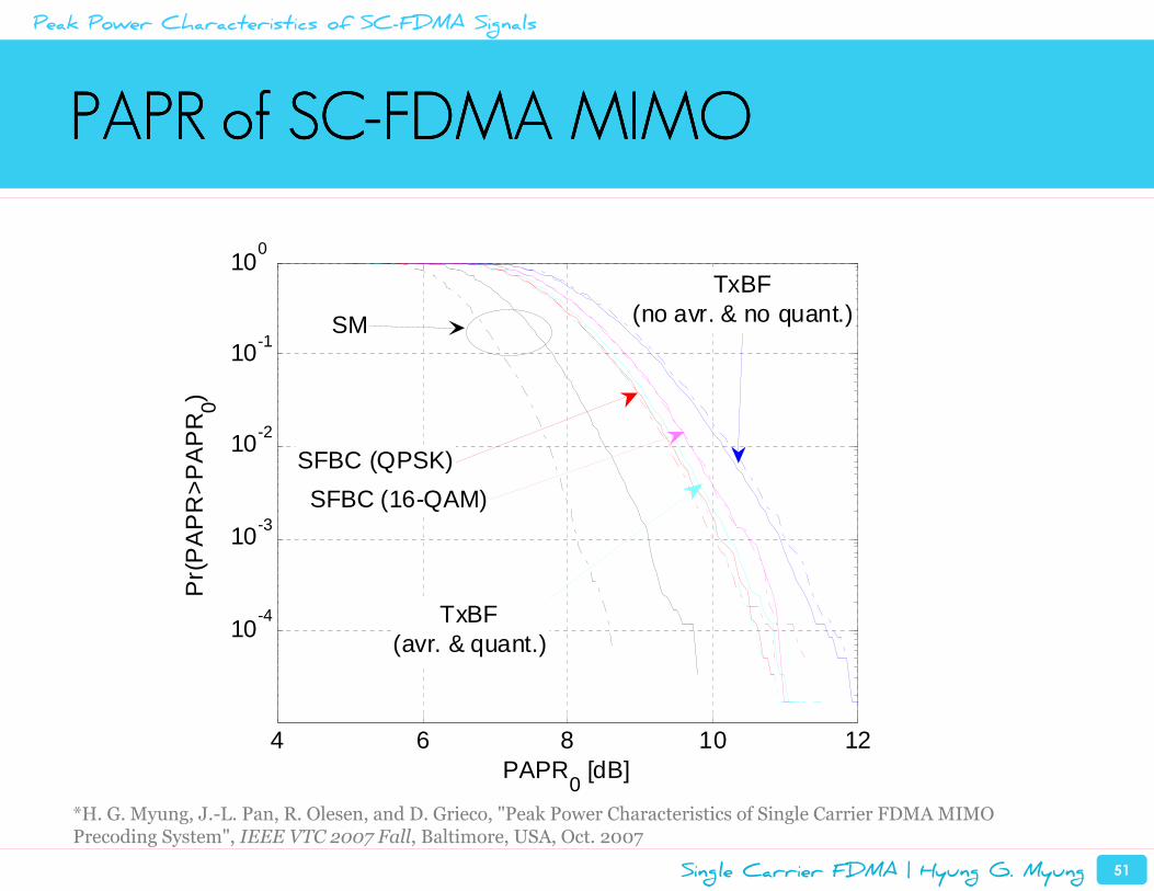
PAPR of SCPAPR of SCPAPR of SCPAPR of SC----FDMA FDMA FDMA FDMA MIMOMIMOMIMOMIMO
4 6 8 10 12
10-4
10-3
10-2
10-1
100
PAPR0 [dB]
Pr(
PA
PR
>P
AP
R0)
SM
SFBC (QPSK)
SFBC (16-QAM)
TxBF(avr. & quant.)
TxBF(no avr. & no quant.)
Peak Power Characteristics of SC-FDMA Signals
*H. G. Myung, J.-L. Pan, R. Olesen, and D. Grieco, "Peak Power Characteristics of Single Carrier FDMA MIMO Precoding System", IEEE VTC 2007 Fall, Baltimore, USA, Oct. 2007
Introduction and Background
Overview of SC-FDMA
SC-FDMA Implementation in 3GPP LTE
Peak Power Characteristics of SC-FDMA Signals
Uplink Resource Scheduling in SC-FDMA Systems
Summary and Conclusions
Single Carrier FDMA | Hyung G. Myung 53
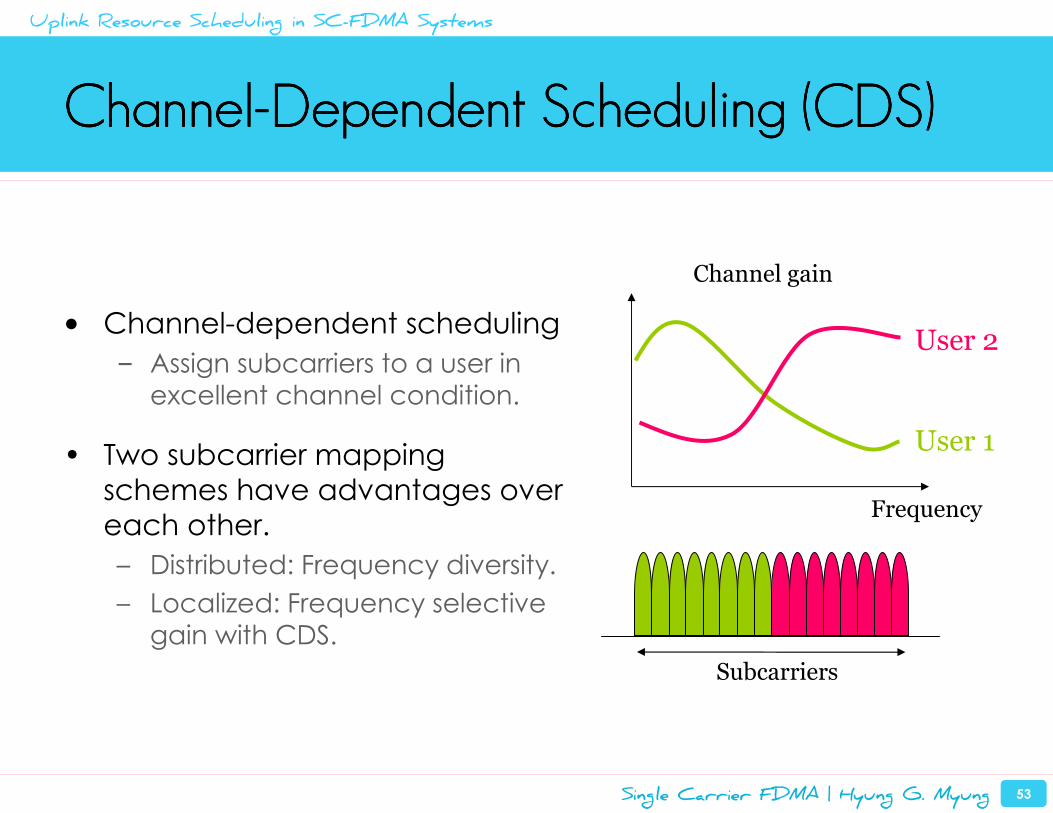
ChannelChannelChannelChannel----Dependent Scheduling (CDS)Dependent Scheduling (CDS)Dependent Scheduling (CDS)Dependent Scheduling (CDS)
• Channel-dependent scheduling
– Assign subcarriers to a user in
excellent channel condition.
• Two subcarrier mapping
schemes have advantages over
each other.
– Distributed: Frequency diversity.
– Localized: Frequency selective
gain with CDS.
Subcarriers
Frequency
User 1
User 2
Channel gain
Uplink Resource Scheduling in SC-FDMA Systems
Single Carrier FDMA | Hyung G. Myung 54
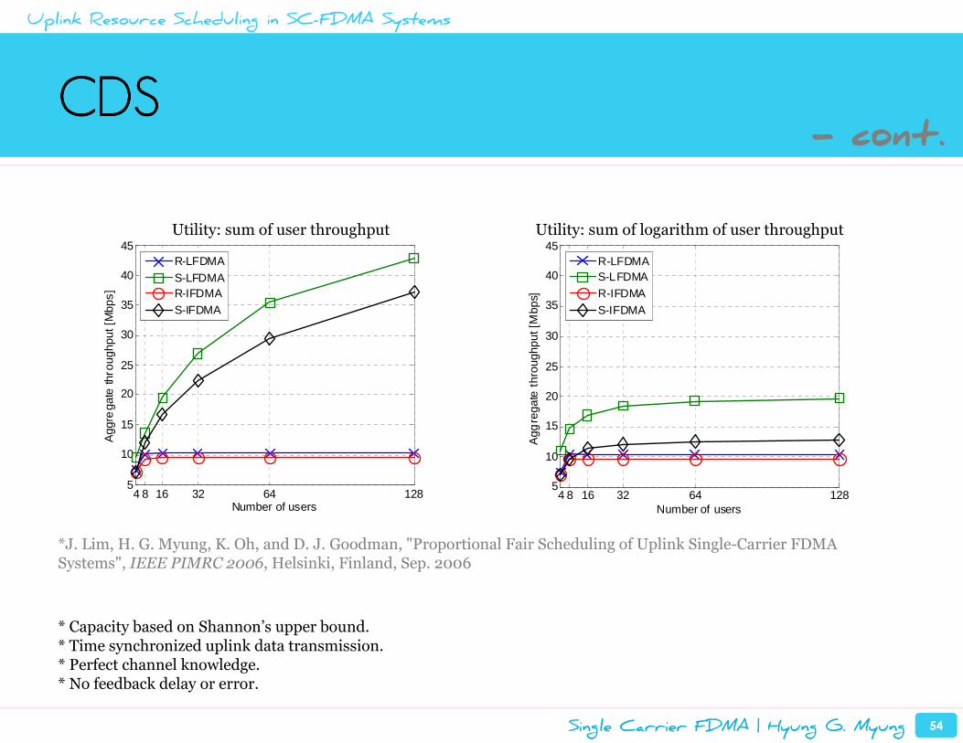
CDSCDSCDSCDS
*J. Lim, H. G. Myung, K. Oh, and D. J. Goodman, "Proportional Fair Scheduling of Uplink Single-Carrier FDMA Systems", IEEE PIMRC 2006, Helsinki, Finland, Sep. 2006
4 8 16 32 64 1285
10
15
20
25
30
35
40
45
Number of users
Agg
rega
te th
roug
hput
[Mbp
s]
R-LFDMA
S-LFDMAR-IFDMAS-IFDMA
4 8 16 32 64 1285
10
15
20
25
30
35
40
45
Number of users
Agg
rega
te th
roug
hput
[Mbp
s]
R-LFDMAS-LFDMAR-IFDMA
S-IFDMA
Utility: sum of user throughput Utility: sum of logarithm of user throughput
* Capacity based on Shannon’s upper bound.* Time synchronized uplink data transmission.* Perfect channel knowledge.* No feedback delay or error.
Uplink Resource Scheduling in SC-FDMA Systems
- cont.
Single Carrier FDMA | Hyung G. Myung 55
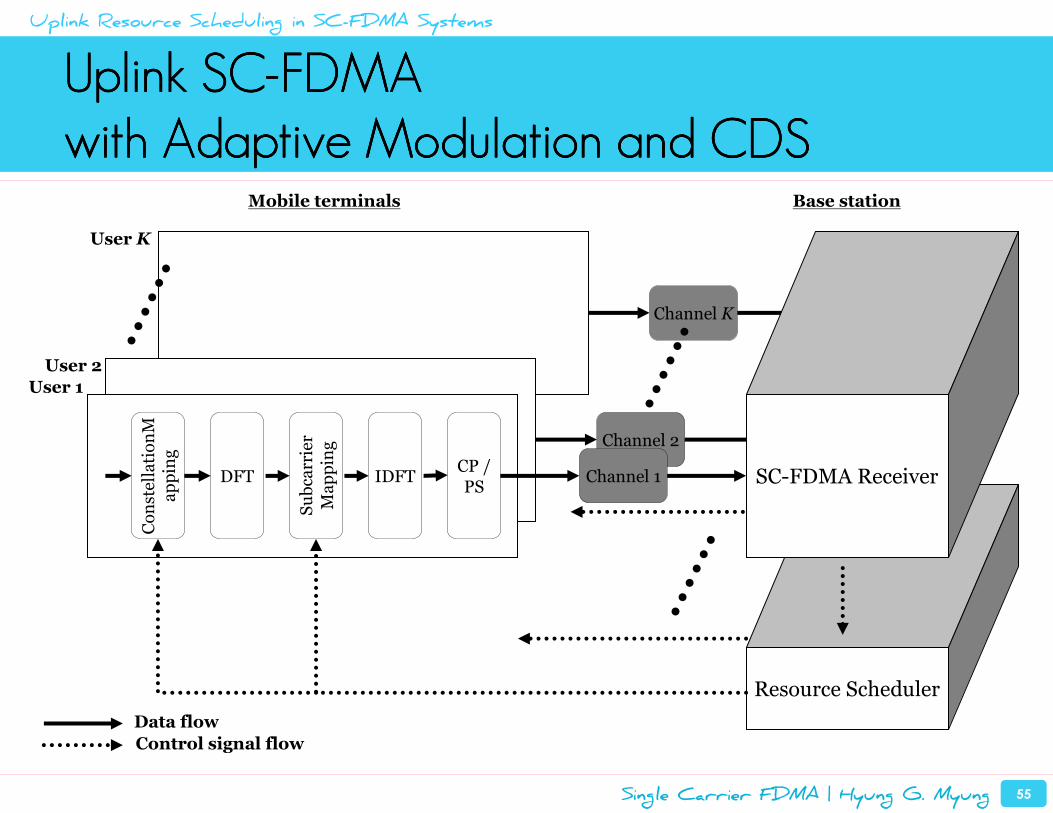
Uplink SCUplink SCUplink SCUplink SC----FDMAFDMAFDMAFDMA
with Adaptive Modulation and CDSwith Adaptive Modulation and CDSwith Adaptive Modulation and CDSwith Adaptive Modulation and CDS
Channel K
Resource Scheduler
Channel 2
Subcarrier
Mapping
Channel 1IDFTCP / PS
DFT
ConstellationM
apping
SC-FDMA Receiver
User 1
User 2
User K
Data flow
Control signal flow
Mobile terminals Base station
Uplink Resource Scheduling in SC-FDMA Systems
Single Carrier FDMA | Hyung G. Myung 56
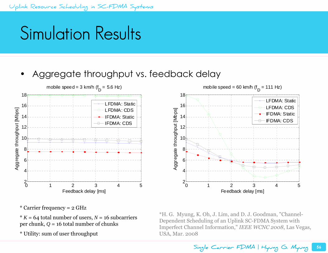
Simulation ResultsSimulation ResultsSimulation ResultsSimulation Results
• Aggregate throughput vs. feedback delay
0 1 2 3 4 52
4
6
8
10
12
14
16
18
Feedback delay [ms]
Agg
rega
te th
roug
hpu
t [M
bps]
mobile speed = 3 km/h (fD
= 5.6 Hz)
LFDMA: StaticLFDMA: CDSIFDMA: StaticIFDMA: CDS
0 1 2 3 4 52
4
6
8
10
12
14
16
18
Feedback delay [ms]
Agg
rega
te t
hrou
ghpu
t [M
bps
]
mobile speed = 60 km/h (fD = 111 Hz)
LFDMA: Static
LFDMA: CDSIFDMA: Static
IFDMA: CDS
* Carrier frequency = 2 GHz
* K = 64 total number of users, N = 16 subcarriers per chunk, Q = 16 total number of chunks
* Utility: sum of user throughput
Uplink Resource Scheduling in SC-FDMA Systems
*H. G. Myung, K. Oh, J. Lim, and D. J. Goodman, "Channel-Dependent Scheduling of an Uplink SC-FDMA System with Imperfect Channel Information," IEEE WCNC 2008, Las Vegas, USA, Mar. 2008
Single Carrier FDMA | Hyung G. Myung 57
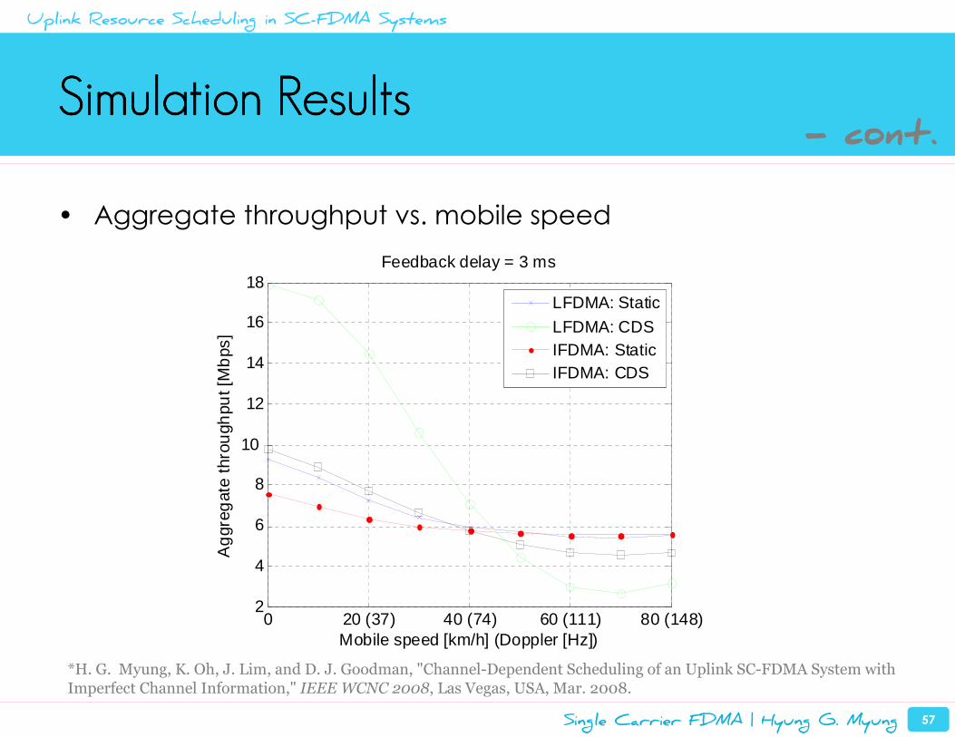
Simulation ResultsSimulation ResultsSimulation ResultsSimulation Results
• Aggregate throughput vs. mobile speed
0 20 (37) 40 (74) 60 (111) 80 (148)2
4
6
8
10
12
14
16
18
Mobile speed [km/h] (Doppler [Hz])
Ag
greg
ate
thro
ugh
put [
Mb
ps]
Feedback delay = 3 ms
LFDMA: Static
LFDMA: CDSIFDMA: StaticIFDMA: CDS
Uplink Resource Scheduling in SC-FDMA Systems
- cont.
*H. G. Myung, K. Oh, J. Lim, and D. J. Goodman, "Channel-Dependent Scheduling of an Uplink SC-FDMA System with Imperfect Channel Information," IEEE WCNC 2008, Las Vegas, USA, Mar. 2008.
Introduction and Background
Overview of SC-FDMA
SC-FDMA Implementation in 3GPP LTE
Peak Power Characteristics of SC-FDMA Signals
Uplink Resource Scheduling in SC-FDMA Systems
Summary and Conclusions
Single Carrier FDMA | Hyung G. Myung 59
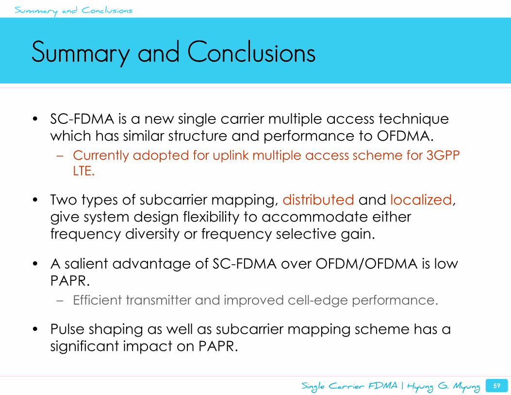
Summary and ConclusionsSummary and ConclusionsSummary and ConclusionsSummary and Conclusions
• SC-FDMA is a new single carrier multiple access technique
which has similar structure and performance to OFDMA.
– Currently adopted for uplink multiple access scheme for 3GPP
LTE.
• Two types of subcarrier mapping, distributed and localized,
give system design flexibility to accommodate either
frequency diversity or frequency selective gain.
• A salient advantage of SC-FDMA over OFDM/OFDMA is low
PAPR.
– Efficient transmitter and improved cell-edge performance.
• Pulse shaping as well as subcarrier mapping scheme has a
significant impact on PAPR.
Summary and Conclusions
Single Carrier FDMA | Hyung G. Myung 60
References and ResourcesReferences and ResourcesReferences and ResourcesReferences and Resources
• H. G. Myung, J. Lim, & D. J. Goodman, “Single Carrier FDMA for Uplink Wireless Transmission,” IEEE Vehic. Tech. Mag., vol. 1, no. 3, Sep. 2006
• H. Ekström et al., “Technical Solutions for the 3G Long-Term Evolution,” IEEE Commun. Mag., vol. 44, no. 3, Mar. 2006
• D. Falconer et al., “Frequency Domain Equalization for Single-Carrier Broadband Wireless Systems,” IEEE Commun. Mag., vol. 40, no. 4, Apr. 2002
• H. Sari et al., “Transmission Techniques for Digital Terrestrial TV Broadcasting,” IEEE Commun. Mag., vol. 33, no. 2, Feb. 1995
Summary and Conclusions
Single Carrier FDMA | Hyung G. Myung 61
References and ResourcesReferences and ResourcesReferences and ResourcesReferences and Resources
• LTE Spec– http://www.3gpp.org/ftp/Specs/html-info/36-series.htm
• SC-FDMA resource page– http://hgmyung.googlepages.com/scfdma
• Comprehensive list of SC-FDMA papers– http://hgmyung.googlepages.com/scfdma2
Summary and Conclusions
- cont.
Single Carrier FDMA | Hyung G. Myung 62
Final WordFinal WordFinal WordFinal Word
SC-FDMA Low PAPR�
Summary and Conclusions