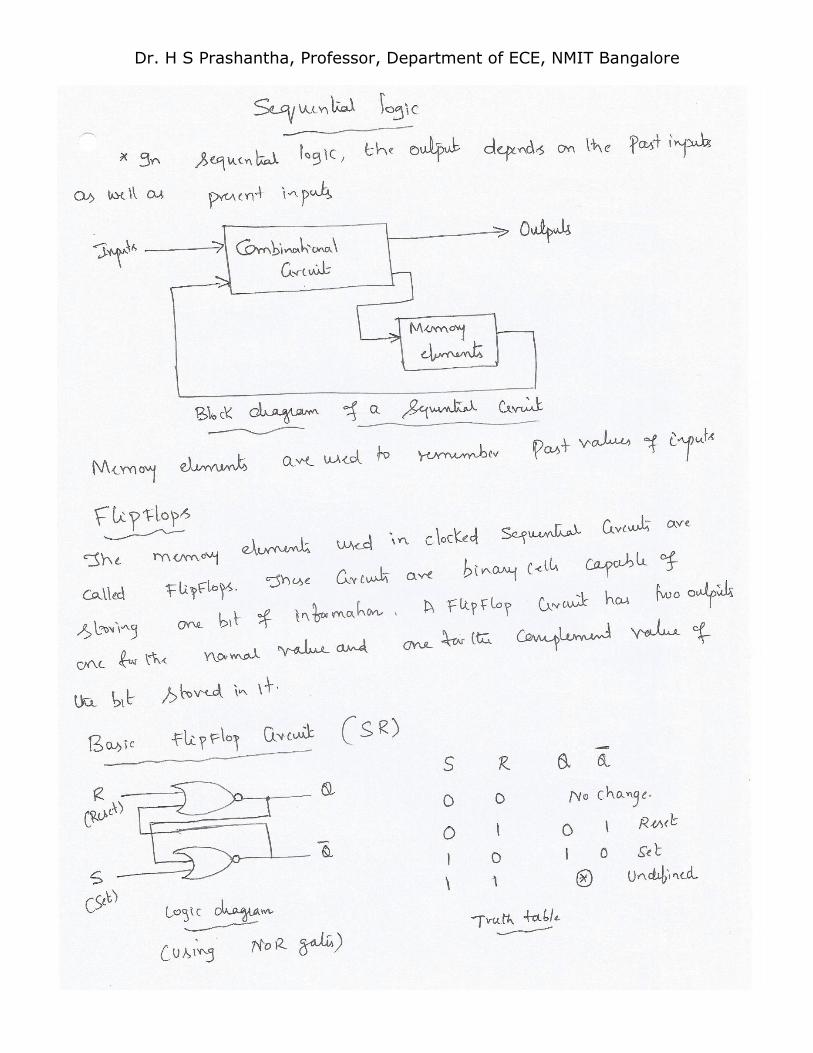
Page 1
Dr. H S Prashantha, Professor, Department of ECE, NMIT Bangalore
1
UNIT 1
NUMBER SYSTEM AND DIGITAL LOGIC
NUMBER SYSTEM:
Introduction
Decimal, Binary, Octal & hexadecimal number system conversion
Compliments (only 2’s,1’s,10’s & 9’s compliment)
Addition and Subtraction ( Binary and Decimal number system)
Binary coded number (BCD)
1. INTRODUCTION:
There are different numbering systems used in digital electronic circuits and computers. However, the
numbering system used in one type of circuit may be different to that of another type of circuit, for
example, the memory of a computer would use hexadecimal numbers while the keyboard uses decimal
numbers. The different number systems are
Decimal – The decimal numbering system has a base of 10 (MOD-10) and uses the digits from
0 through 9 to represent a decimal number value.
Binary – The binary numbering system has a base of 2 (MOD-2) and uses only two digits a “0” and a
“1” to represent a binary number value.
Octal – The octal numbering system has a base of 8 (MOD-8) and uses 8 digits between 0 and 7 to
represent an octal number value.
Hexadecimal – The Hexadecimal numbering system has a base of 16 (MOD-16) and uses a total of 16
numeric and alphabetic characters to represent a number value. Hexadecimal numbers consist of
digits 0 through 9 and letters A to F.
Long binary numbers are difficult to read or write and are generally converted into a different system
which is user friendly. The two most common derivatives based on binary numbers are the Octal and
the Hexadecimal numbering systems, with both of these limited in length to a byte (8-bits) or a word
(16-bits). Octal numbers can be represented by groups of 3-bits and hexadecimal numbers by groups of
4-bits together, with this grouping of the bits being used in electronic or computer systems in displays or
printouts.
The Comparisons between the various Decimal, Binary, Hexadecimal and Octal numbers are given in
the following table.
Base or radix Byte (8-bits) Word (16-bits)
Decimal 0 to 255(10) 0 to 65,535(10)
Binary 00000000 to 11111111(2) 0000000000000000 to 1111111111111111(2)
Hexadecimal 00 to FF(16) 0000 to FFFF(16)
Octal 000 to 377(8) 000000 to 177777(8)
Page 2
Dr. H S Prashantha, Professor, Department of ECE, NMIT Bangalore
2
We can see from the table above that the Hexadecimal numbering system uses only four digits to express
a single 16-bit word length, and as a result it is the most commonly used Base Numbering System for
digital, micro-electronics and computer systems.
2. NUMBER SYSTEM
2.1 Decimal Number System
In the decimal number system, each integer number column has values of units, tens, hundreds,
thousands, etc as we move along the number from right to left. Mathematically these values are written
as 100, 101, 102, 103 etc. Then each position to the left of the decimal point indicates an increased positive
power of 10. Likewise, for fractional numbers the weight of the number becomes more negative as we
move from left to right, 10-1, 10-2, 10-3 etc.
The value of any decimal number will be equal to the sum of its digits multiplied by their respective
weights. For example: N = 616310 (Six Thousand One Hundred and Sixty Three) in a decimal format is
equal to:
6000 + 100 + 60 + 3 = 6163
Or it can be written reflecting the weight of each digit as:
(6×1000) + (1×100) + (6×10) + (3×1) = 6163
Or it can be written in polynomial form as:
(6×10³) + (1×10²) + (6×101) + (3×100) = 6163
Where in this decimal numbering system example, the left most digit is the most significant digit, or MSD,
and the right most digit is the least significant digit or LSD. In other words, the digit 6 is the MSD since
its left most position carries the most weight, and the number 3 is the LSD as its right most position
carries the least weight.
2.2 Binary Number System
The Binary Number System is the most fundamental number system in all digital and computer based
systems and binary numbers follow the same set of rules as the decimal numbering system. But unlike
the decimal system which uses powers of ten, the binary numbering system works on powers of two
giving a binary to decimal conversion from base-2 to base-10. Digital logic and computer systems use
just two values or states to represent a condition, a logic level “1” or a logic level “0”, and each “0” and
“1” is considered to be a single digit in a Base-of-2 or “binary number system”.
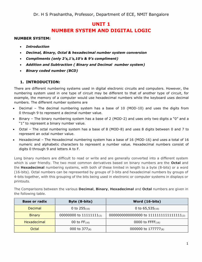
In electronics, binary numbers is the flow of information in the form of zeros and ones used by digital
computers and systems. Generally, a logic “1” represents a higher voltage, such as 5 volts, which is
commonly referred to as a HIGH value, while a logic “0” represents a low voltage, such as 0 volts or
ground, and is commonly referred to as a LOW value. These two discrete voltage levels representing the
digital values of “1’s” (one’s) and “0’s” (zero’s) are commonly called: BInary digiTS, and in digital and
computational circuits and applications they are normally referred to as binary BITS.
Figure 1: Binary Bits of Zeros and Ones
Page 3
Dr. H S Prashantha, Professor, Department of ECE, NMIT Bangalore
3
Because there are only two valid Boolean values for representing either a logic “1” or a logic “0”, makes
the system of using Binary Numbers ideal for use in digital or electronic circuits and systems.
Digital waveforms or signals consist of discrete or distinctive voltage levels that are changing back and
forth between these two “HIGH” and “LOW” states. But what makes a signal or voltage “Digital” and how
can we represent these “HIGH” and “LOW” voltage levels. Electronic circuits and systems can be divided
into two main categories.
Analog Circuits – Analogue or Linear circuits amplify or respond to continuously varying voltage
levels that can alternate between a positive and negative value over a period of time.
Digital Circuits – Digital circuits produce or respond too two distinct positive or negative voltage
levels representing either a logic level “1” or a logic level “0”.
In the binary number system, a binary number such as 101100101 is expressed with a string of “1’s” and
“0’s” with each digit along the string from right to left having a value twice that of the previous digit.
As the decimal number is a weighted number, converting from decimal to binary (base 10 to base 2) will
also produce a weighted binary number with the right-hand most bit being the Least Significant Bit or LSB,
and the left-hand most bit being the Most Significant Bit or MSB, and we can represent this as:
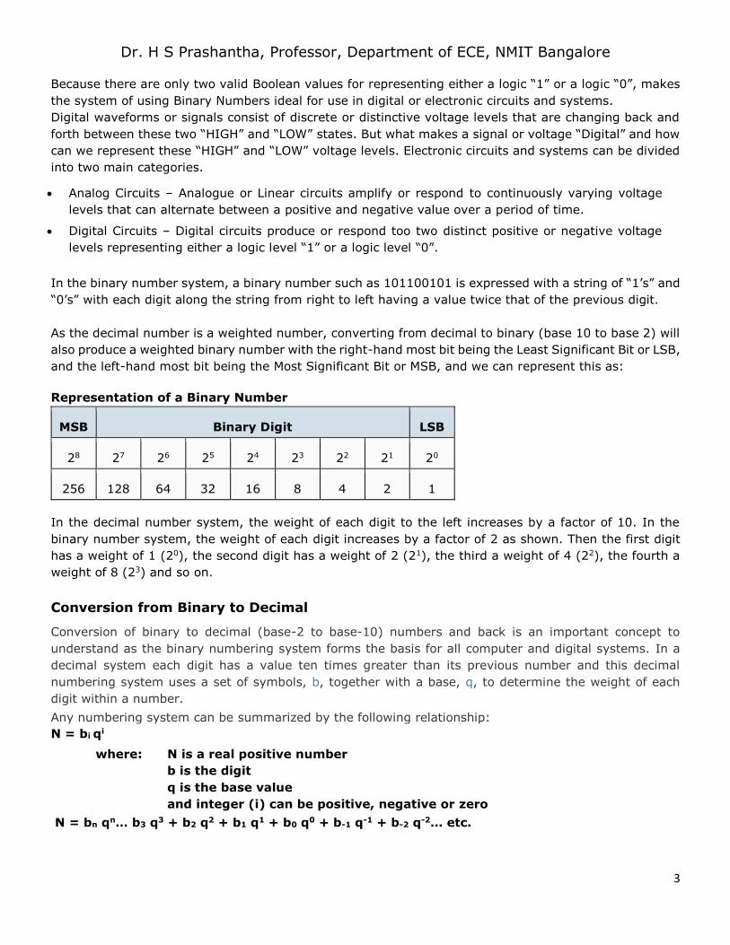
Representation of a Binary Number
MSB Binary Digit LSB
28 27 26 25 24 23 22 21 20
256 128 64 32 16 8 4 2 1
In the decimal number system, the weight of each digit to the left increases by a factor of 10. In the
binary number system, the weight of each digit increases by a factor of 2 as shown. Then the first digit
has a weight of 1 (20), the second digit has a weight of 2 (21), the third a weight of 4 (22), the fourth a
weight of 8 (23) and so on.
Conversion from Binary to Decimal
Conversion of binary to decimal (base-2 to base-10) numbers and back is an important concept to
understand as the binary numbering system forms the basis for all computer and digital systems. In a
decimal system each digit has a value ten times greater than its previous number and this decimal
numbering system uses a set of symbols, b, together with a base, q, to determine the weight of each
digit within a number.
Any numbering system can be summarized by the following relationship:
N = bi qi
where: N is a real positive number
b is the digit
q is the base value
and integer (i) can be positive, negative or zero
N = bn qn… b3 q3 + b2 q2 + b1 q1 + b0 q0 + b-1 q-1 + b-2 q-2… etc.
Page 4
Dr. H S Prashantha, Professor, Department of ECE, NMIT Bangalore
4
We can convert binary to decimal by finding the decimal equivalent of the binary array of digits
1011001012 and expanding the binary digits into a series with a base of 2 giving an equivalent of 35710 in
decimal or denary.
For example, converting a Binary to Decimal number would be:
Decimal Digit Value 256 128 64 32 16 8 4 2 1
Binary Digit Value 1 0 1 1 0 0 1 0 1
By adding together ALL the decimal number values from right to left at the positions that are represented
by a “1” gives us: (256)+(64)+(32)+(4)+(1) = 35710 or three hundred and fifty seven as a decimal
number.
Conversion from Decimal to binary
Repeated Division-by-2 Method
An easy method of converting decimal to binary number equivalents is to write down the decimal number
and to continually divide-by-2 (two) to give a result and a remainder of either a “1” or a “0” until the final
result equals zero.
So for example. Convert the decimal number 29410 into its binary number equivalent.
Number 294
Dividing each decimal number by “2”
as shown will give a result plus a
remainder.
If the decimal number being divided
is even then the result will be whole
and the remainder will be equal to
“0”. If the decimal number is odd
then the result will not divide
completely and the remainder will be
a “1”.
The binary result is obtained by
placing all the remainders in order
with the least significant bit (LSB)
being at the top and the most
significant bit (MSB) being at the
bottom.
divide by 2
result 147 remainder 0 (LSB)
divide by 2
result 73 remainder 1
divide by 2
result 36 remainder 1
divide by 2
result 18 remainder 0
divide by 2
result 9 remainder 0
divide by 2
result 4 remainder 1
divide by 2
result 2 remainder 0
divide by 2
result 1 remainder 0
divide by 2
result 0 remainder 1 (MSB)
This divide-by-2 decimal to binary conversion technique gives the decimal number 29410 an equivalent
of 1001001102 in binary, reading from right to left. This divide-by-2 method will also work for conversion
to other number bases.
Page 5
Dr. H S Prashantha, Professor, Department of ECE, NMIT Bangalore
5
The main characteristics of a Binary Number System is that each “binary digit” or “bit” has a value of
either “1” or “0” with each bit having a weight or value double that of its previous bit starting from the
lowest or least significant bit (LSB) and this is called the “sum-of-weights” method.
Hence we can convert a decimal number into a binary number either by using the sum-of-weights method
or by using the repeated division-by-2 method, and convert binary to decimal by finding its sum-of-
weights.
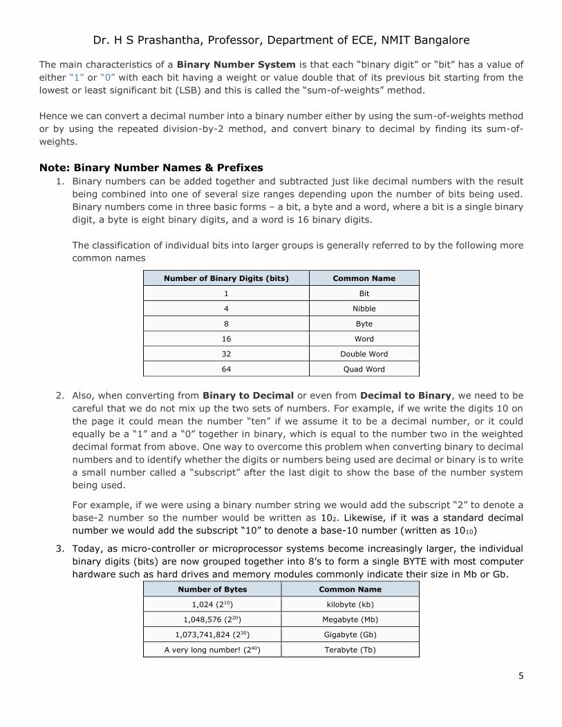
Note: Binary Number Names & Prefixes
1. Binary numbers can be added together and subtracted just like decimal numbers with the result
being combined into one of several size ranges depending upon the number of bits being used.
Binary numbers come in three basic forms – a bit, a byte and a word, where a bit is a single binary
digit, a byte is eight binary digits, and a word is 16 binary digits.
The classification of individual bits into larger groups is generally referred to by the following more
common names
Number of Binary Digits (bits) Common Name
1 Bit
4 Nibble
8 Byte
16 Word
32 Double Word
64 Quad Word
2. Also, when converting from Binary to Decimal or even from Decimal to Binary, we need to be
careful that we do not mix up the two sets of numbers. For example, if we write the digits 10 on
the page it could mean the number “ten” if we assume it to be a decimal number, or it could
equally be a “1” and a “0” together in binary, which is equal to the number two in the weighted
decimal format from above. One way to overcome this problem when converting binary to decimal
numbers and to identify whether the digits or numbers being used are decimal or binary is to write
a small number called a “subscript” after the last digit to show the base of the number system
being used.
For example, if we were using a binary number string we would add the subscript “2” to denote a
base-2 number so the number would be written as 102. Likewise, if it was a standard decimal
number we would add the subscript “10” to denote a base-10 number (written as 1010)
3. Today, as micro-controller or microprocessor systems become increasingly larger, the individual
binary digits (bits) are now grouped together into 8’s to form a single BYTE with most computer
hardware such as hard drives and memory modules commonly indicate their size in Mb or Gb.
Number of Bytes Common Name
1,024 (210) kilobyte (kb)
1,048,576 (220) Megabyte (Mb)
1,073,741,824 (230) Gigabyte (Gb)
A very long number! (240) Terabyte (Tb)
Page 6
Dr. H S Prashantha, Professor, Department of ECE, NMIT Bangalore
6
Binary to Decimal Summary
A “BIT” is the abbreviated term derived from BInary digiT
A Binary system has only two states, Logic “0” and Logic “1” giving a base of 2
A Decimal system uses 10 different digits, 0 to 9 giving it a base of 10
A Binary number is a weighted number who’s weighted value increases from right to left
The weight of a binary digit doubles from right to left
A decimal number can be converted to a binary number by using the sum-of-weights method or the
repeated division-by-2 method
When we convert numbers from binary to decimal, or decimal to binary, subscripts are used to avoid
errors. Converting binary to decimal (base-2 to base-10) or decimal to Binary Numbers (base10 to
base-2) can be done in a number of different ways as shown above. When converting decimal numbers
to binary numbers it is important to remember which the least significant bit (LSB) is, and which the
most significant bit (MSB) is.
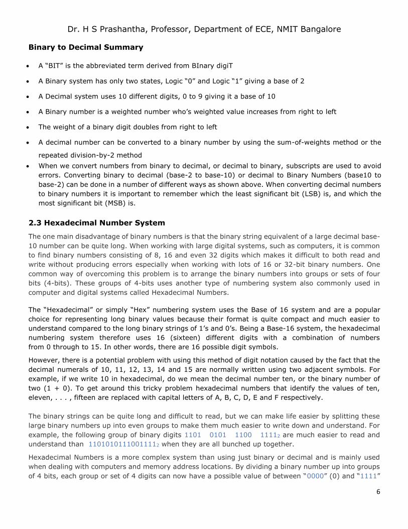
2.3 Hexadecimal Number System
The one main disadvantage of binary numbers is that the binary string equivalent of a large decimal base-
10 number can be quite long. When working with large digital systems, such as computers, it is common
to find binary numbers consisting of 8, 16 and even 32 digits which makes it difficult to both read and
write without producing errors especially when working with lots of 16 or 32-bit binary numbers. One
common way of overcoming this problem is to arrange the binary numbers into groups or sets of four
bits (4-bits). These groups of 4-bits uses another type of numbering system also commonly used in
computer and digital systems called Hexadecimal Numbers.
The “Hexadecimal” or simply “Hex” numbering system uses the Base of 16 system and are a popular
choice for representing long binary values because their format is quite compact and much easier to
understand compared to the long binary strings of 1’s and 0’s. Being a Base-16 system, the hexadecimal
numbering system therefore uses 16 (sixteen) different digits with a combination of numbers
from 0 through to 15. In other words, there are 16 possible digit symbols.
However, there is a potential problem with using this method of digit notation caused by the fact that the
decimal numerals of 10, 11, 12, 13, 14 and 15 are normally written using two adjacent symbols. For
example, if we write 10 in hexadecimal, do we mean the decimal number ten, or the binary number of
two (1 + 0). To get around this tricky problem hexadecimal numbers that identify the values of ten,
eleven, . . . , fifteen are replaced with capital letters of A, B, C, D, E and F respectively.
The binary strings can be quite long and difficult to read, but we can make life easier by splitting these
large binary numbers up into even groups to make them much easier to write down and understand. For
example, the following group of binary digits 1101 0101 1100 11112 are much easier to read and
understand than 11010101110011112 when they are all bunched up together.
Hexadecimal Numbers is a more complex system than using just binary or decimal and is mainly used
when dealing with computers and memory address locations. By dividing a binary number up into groups
of 4 bits, each group or set of 4 digits can now have a possible value of between “0000” (0) and “1111”
Page 7
Dr. H S Prashantha, Professor, Department of ECE, NMIT Bangalore
7
( 8+4+2+1 = 15 ) giving a total of 16 different number combinations from 0 to 15. Don’t forget that “0”
is also a valid digit.
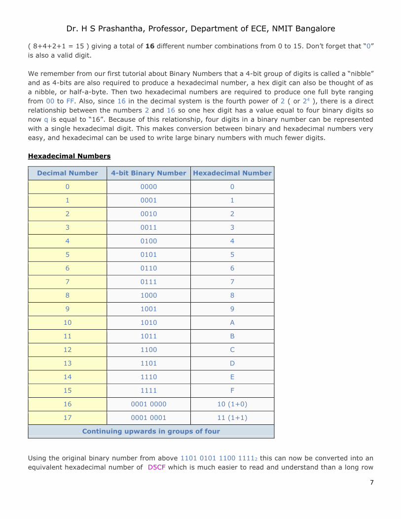
We remember from our first tutorial about Binary Numbers that a 4-bit group of digits is called a “nibble”
and as 4-bits are also required to produce a hexadecimal number, a hex digit can also be thought of as
a nibble, or half-a-byte. Then two hexadecimal numbers are required to produce one full byte ranging
from 00 to FF. Also, since 16 in the decimal system is the fourth power of 2 ( or 24 ), there is a direct
relationship between the numbers 2 and 16 so one hex digit has a value equal to four binary digits so
now q is equal to “16”. Because of this relationship, four digits in a binary number can be represented
with a single hexadecimal digit. This makes conversion between binary and hexadecimal numbers very
easy, and hexadecimal can be used to write large binary numbers with much fewer digits.
Hexadecimal Numbers
Decimal Number 4-bit Binary Number Hexadecimal Number
0 0000 0
1 0001 1
2 0010 2
3 0011 3
4 0100 4
5 0101 5
6 0110 6
7 0111 7
8 1000 8
9 1001 9
10 1010 A
11 1011 B
12 1100 C
13 1101 D
14 1110 E
15 1111 F
16 0001 0000 10 (1+0)
17 0001 0001 11 (1+1)
Continuing upwards in groups of four
Using the original binary number from above 1101 0101 1100 11112 this can now be converted into an
equivalent hexadecimal number of D5CF which is much easier to read and understand than a long row
Page 8
Dr. H S Prashantha, Professor, Department of ECE, NMIT Bangalore
8
of 1’s and 0’s that we had before. So by using hexadecimal notation, the numbers can be written with
fewer digits and much less likelihood of error. Similarly, converting hexadecimal based numbers back into
binary is simply the reverse operation.
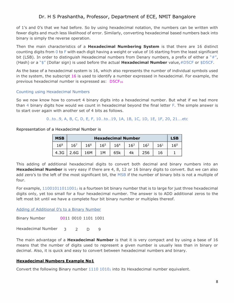
Then the main characteristics of a Hexadecimal Numbering System is that there are 16 distinct
counting digits from 0 to F with each digit having a weight or value of 16 starting from the least significant
bit (LSB). In order to distinguish Hexadecimal numbers from Denary numbers, a prefix of either a “#”,
(Hash) or a “$” (Dollar sign) is used before the actual Hexadecimal Number value,#D5CF or $D5CF.
As the base of a hexadecimal system is 16, which also represents the number of individual symbols used
in the system, the subscript 16 is used to identify a number expressed in hexadecimal. For example, the
previous hexadecimal number is expressed as: D5CF16
Counting using Hexadecimal Numbers
So we now know how to convert 4 binary digits into a hexadecimal number. But what if we had more
than 4 binary digits how would we count in hexadecimal beyond the final letter F. The simple answer is
to start over again with another set of 4 bits as follows.
0…to…9, A, B, C, D, E, F, 10…to…19, 1A, 1B, 1C, 1D, 1E, 1F, 20, 21….etc
Representation of a Hexadecimal Number is
MSB Hexadecimal Number LSB
168 167 166 165 164 163 162 161 160
4.3G 2.6G 16M 1M 65k 4k 256 16 1
This adding of additional hexadecimal digits to convert both decimal and binary numbers into an
Hexadecimal Number is very easy if there are 4, 8, 12 or 16 binary digits to convert. But we can also
add zero’s to the left of the most significant bit, the MSB if the number of binary bits is not a multiple of
four.
For example, 110010110110012 is a fourteen bit binary number that is to large for just three hexadecimal
digits only, yet too small for a four hexadecimal number. The answer is to ADD additional zeros to the
left most bit until we have a complete four bit binary number or multiples thereof.
Adding of Additional 0’s to a Binary Number
Binary Number 0011 0010 1101 1001
Hexadecimal Number 3 2 D 9
The main advantage of a Hexadecimal Number is that it is very compact and by using a base of 16
means that the number of digits used to represent a given number is usually less than in binary or
decimal. Also, it is quick and easy to convert between hexadecimal numbers and binary.
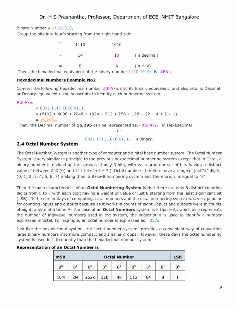
Hexadecimal Numbers Example No1
Convert the following Binary number 1110 10102 into its Hexadecimal number equivalent.
Page 9
Dr. H S Prashantha, Professor, Department of ECE, NMIT Bangalore
9
Binary Number = 111010102
Group the bits into four’s starting from the right hand side
=
1110
1010
=
14
10 (in decimal)
=
E
A (in Hex)
Then, the hexadecimal equivalent of the binary number 1110 10102 is #EA16
Hexadecimal Numbers Example No2
Convert the following Hexadecimal number #3FA716 into its Binary equivalent, and also into its Decimal
or Denary equivalent using subscripts to identify each numbering system.
#3FA716
= 0011 1111 1010 01112
= (8192 + 4096 + 2048 + 1024 + 512 + 256 + 128 + 32 + 4 + 2 + 1)
= 16,29510
Then, the Decimal number of 16,295 can be represented as:- #3FA716 in Hexadecimal
or
0011 1111 1010 01112 in Binary.
2.4 Octal Number System
The Octal Number System is another type of computer and digital base number system. The Octal Number
System is very similar in principle to the previous hexadecimal numbering system except that in Octal, a
binary number is divided up into groups of only 3 bits, with each group or set of bits having a distinct
value of between 000 (0) and 111 ( 4+2+1 = 7 ). Octal numbers therefore have a range of just “8” digits,
(0, 1, 2, 3, 4, 5, 6, 7) making them a Base-8 numbering system and therefore, q is equal to “8”.
Then the main characteristics of an Octal Numbering System is that there are only 8 distinct counting
digits from 0 to 7 with each digit having a weight or value of just 8 starting from the least significant bit
(LSB). In the earlier days of computing, octal numbers and the octal numbering system was very popular
for counting inputs and outputs because as it works in counts of eight, inputs and outputs were in counts
of eight, a byte at a time. As the base of an Octal Numbers system is 8 (base-8), which also represents
the number of individual numbers used in the system, the subscript 8 is used to identify a number
expressed in octal. For example, an octal number is expressed as: 2378
Just like the hexadecimal system, the “octal number system” provides a convenient way of converting
large binary numbers into more compact and smaller groups. However, these days the octal numbering
system is used less frequently than the hexadecimal number system
Representation of an Octal Number is
MSB Octal Number LSB
88 87 86 85 84 83 82 81 80
16M 2M 262k 32k 4k 512 64 8 1
Page 10
Dr. H S Prashantha, Professor, Department of ECE, NMIT Bangalore
10
As the octal number system uses only eight digits (0 through 7) there are no numbers or letters used
above 8, but the conversion from decimal to octal and binary to octal follows the same pattern as we
have seen previously for hexadecimal.
To count above 7 in octal we need to add another column and start over again in a similar way to
hexadecimal.
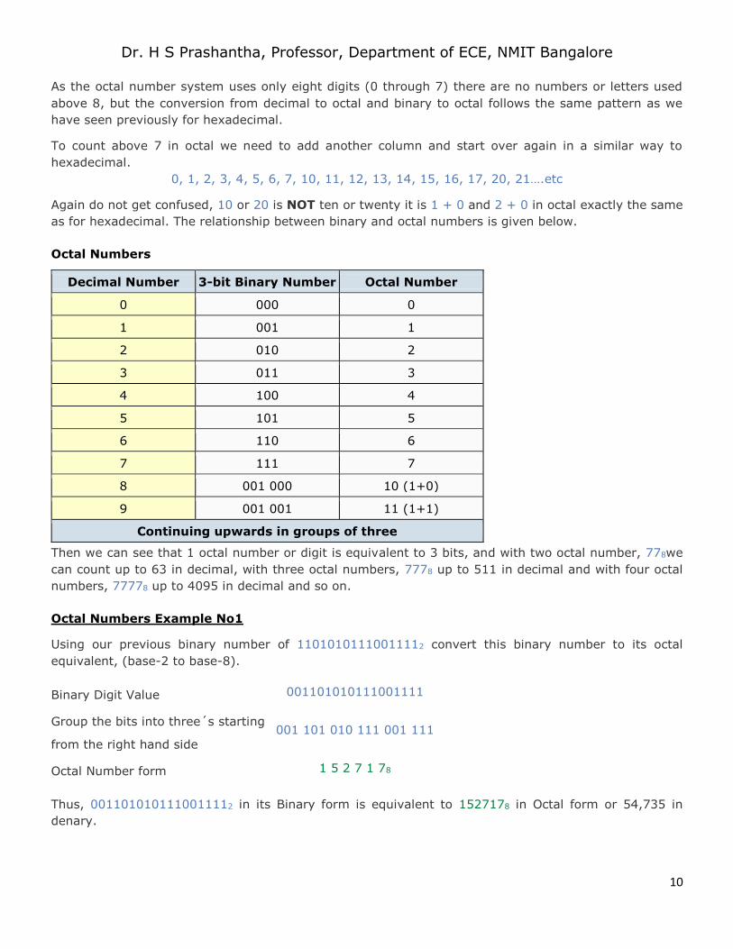
0, 1, 2, 3, 4, 5, 6, 7, 10, 11, 12, 13, 14, 15, 16, 17, 20, 21….etc
Again do not get confused, 10 or 20 is NOT ten or twenty it is 1 + 0 and 2 + 0 in octal exactly the same
as for hexadecimal. The relationship between binary and octal numbers is given below.
Octal Numbers
Decimal Number 3-bit Binary Number Octal Number
0 000 0
1 001 1
2 010 2
3 011 3
4 100 4
5 101 5
6 110 6
7 111 7
8 001 000 10 (1+0)
9 001 001 11 (1+1)
Continuing upwards in groups of three
Then we can see that 1 octal number or digit is equivalent to 3 bits, and with two octal number, 778we
can count up to 63 in decimal, with three octal numbers, 7778 up to 511 in decimal and with four octal
numbers, 77778 up to 4095 in decimal and so on.
Octal Numbers Example No1
Using our previous binary number of 11010101110011112 convert this binary number to its octal
equivalent, (base-2 to base-8).
Binary Digit Value 001101010111001111
Group the bits into three´s starting
from the right hand side
001 101 010 111 001 111
Octal Number form 1 5 2 7 1 78
Thus, 0011010101110011112 in its Binary form is equivalent to 1527178 in Octal form or 54,735 in
denary.
Page 11
Dr. H S Prashantha, Professor, Department of ECE, NMIT Bangalore
11
Octal Numbers Example No2
Convert the octal number 23228 to its decimal number equivalent, (base-8 to base-10).
Octal Digit Value 23228
In polynomial form = ( 2×83 ) + ( 3×82 ) + ( 2×81 ) + ( 2×80 )
Add the results = ( 1024 ) + ( 192 ) + ( 16 ) + ( 2 )
Decimal number form equals: 123410
Then, converting octal to decimal shows that 23228 in its Octal form is equivalent to 123410 in its Decimal
form.
While Octal is another type of digital numbering system, it is little used these days instead the more
commonly used Hexadecimal Numbering System is used as it is more flexible.
1.3 COMPLIMENTS
In mathematics, positive numbers (including zero) are represented as unsigned numbers. That is we do
not put the +ve sign in front of them to show that they are positive numbers. However, when dealing
with negative numbers we do use a -ve sign in front of the number to show that the number is negative
in value and different from a positive unsigned value, and the same is true with signed binary numbers.
However, in digital circuits there is no provision made to put a plus or even a minus sign, since digital
systems operate with binary numbers that are represented in terms of “0’s” and “1’s”. We have seen
previously that an 8-bit byte can have a value from 0 to 255, which are 28 = 256 different combinations
of bits forming a single 8-bit byte. So for example an unsigned binary number such
as:010011012 = 64 + 8 + 4 + 1 = 7710 in decimal. But Digital Systems and computers must also be able
to use and to manipulate negative numbers as well as positive numbers.
Mathematical Numbers are generally made up of a sign and a value (magnitude) in which the sign
indicates whether the number is positive, ( + ) or negative, ( – ) with the value indicating the size of the
number, for example 23, +156 or -274. Presenting numbers is this fashion is called “sign-magnitude”
representation since the left most digit can be used to indicate the sign and the remaining digits the
magnitude or value of the number.
Sign-magnitude notation is the simplest and one of the most common methods of representing positive
and negative numbers either side of zero, (0). Thus negative numbers are obtained simply by changing
the sign of the corresponding positive number as each positive or unsigned number will have a signed
opposite, for example, +2 and -2, +10 and -10, etc.
But how do we represent signed binary numbers if all we have is a bunch of one’s and zero’s. We know
that binary digits, or bits only have two values, either a “1” or a “0”, and conveniently a sign also has
only two values, a “+” or a “–“. Then we can use a single bit to identify the sign of a signed binary
number.
So to represent a positive (N) and a negative (-N) binary number we can use the binary numbers with
sign. For signed binary numbers the most significant bit (MSB) is used as the sign. If the sign bit is “0”,
Page 12
Dr. H S Prashantha, Professor, Department of ECE, NMIT Bangalore
12
this means the number is positive. If the sign bit is “1”, then the number is negative. The remaining bits
are used to represent the magnitude of the binary number in the usual unsigned binary number format.
Then we can see that the Sign-and-Magnitude (SM) notation stores positive and negative values by
dividing the “n” total bits into two parts: 1 bit for the sign and n–1 bits for the value which is a pure
binary number. For example, the decimal number 53 can be expressed as an 8-bit signed binary number
as follows.
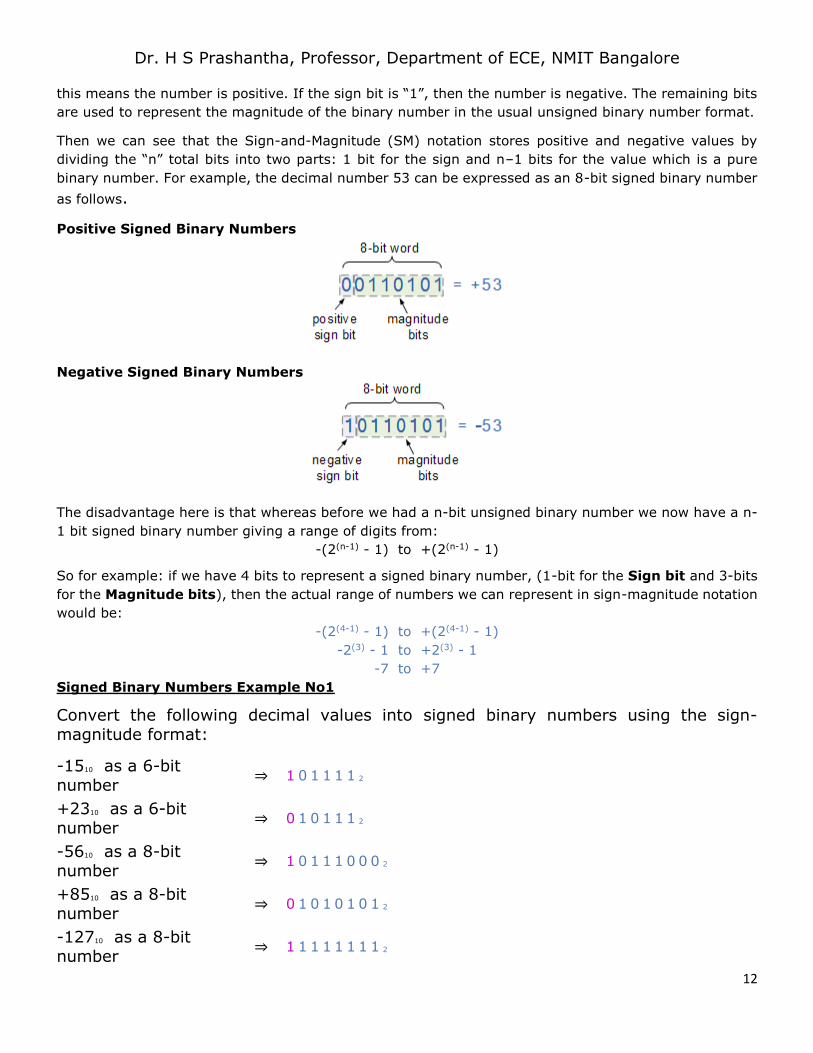
Positive Signed Binary Numbers
Negative Signed Binary Numbers
The disadvantage here is that whereas before we had a n-bit unsigned binary number we now have a n-
1 bit signed binary number giving a range of digits from:
-(2(n-1) - 1) to +(2(n-1) - 1)
So for example: if we have 4 bits to represent a signed binary number, (1-bit for the Sign bit and 3-bits
for the Magnitude bits), then the actual range of numbers we can represent in sign-magnitude notation
would be:
-(2(4-1) - 1) to +(2(4-1) - 1)
-2(3) - 1 to +2(3) - 1
-7 to +7
Signed Binary Numbers Example No1
Convert the following decimal values into signed binary numbers using the sign-magnitude format:
-1510 as a 6-bit number
⇒ 1 0 1 1 1 1 2
+2310 as a 6-bit number
⇒ 0 1 0 1 1 1 2
-5610 as a 8-bit number
⇒ 1 0 1 1 1 0 0 0 2
+8510 as a 8-bit number
⇒ 0 1 0 1 0 1 0 1 2
-12710 as a 8-bit number
⇒ 1 1 1 1 1 1 1 1 2
Page 13
Dr. H S Prashantha, Professor, Department of ECE, NMIT Bangalore
13
Note that for a 4-bit, 6-bit, 8-bit, 16-bit or 32-bit signed binary number all the bits MUST have a value,
therefore “0’s” are used to fill the spaces between the leftmost sign bit and the first or highest value “1”.
The sign-magnitude representation of a binary number is a simple method to use and understand for
representing signed binary numbers, as we use this system all the time with normal decimal (base 10)
numbers in mathematics. Adding a “1” to the front of it if the binary number is negative and a “0” if it is
positive.
However, using this sign-magnitude method can result in the possibility of two different bit patterns
having the same binary value. For example, +0 and -0 would be 0000 and 1000 respectively as a signed
4-bit binary number. So we can see that using this method there can be two representations for zero, a
positive zero ( 00002 ) and also a negative zero ( 10002 ) which can cause big complications for computers
and digital systems.
One’s Complement of a Signed Binary Number
One’s Complement or 1’s Complement as it is also termed, is another method which we can use to
represent negative binary numbers in a signed binary number system. In one’s complement, positive
numbers (also known as non-complements) remain unchanged as before with the sign-magnitude
numbers.
Negative numbers however, are represented by taking the one’s complement (inversion, negation) of the
unsigned positive number. Since positive numbers always start with a “0”, the complement will always
start with a “1” to indicate a negative number.
The one’s complement of a negative binary number is the complement of its positive counterpart, so to
take the one’s complement of a binary number, all we need to do is change each bit in turn. Thus the
one’s complement of “1” is “0” and vice versa, then the one’s complement of 100101002 is
simply011010112 as all the 1’s are changed to 0’s and the 0’s to 1’s.
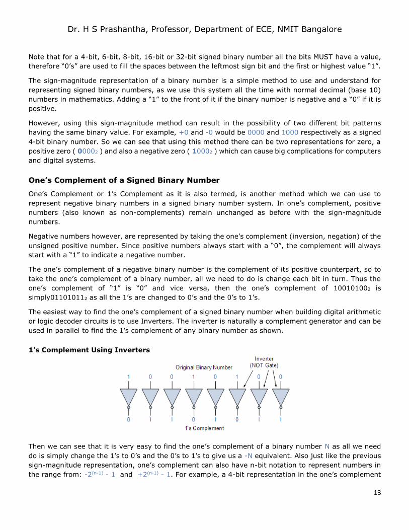
The easiest way to find the one’s complement of a signed binary number when building digital arithmetic
or logic decoder circuits is to use Inverters. The inverter is naturally a complement generator and can be
used in parallel to find the 1’s complement of any binary number as shown.
1’s Complement Using Inverters
Then we can see that it is very easy to find the one’s complement of a binary number N as all we need
do is simply change the 1’s to 0’s and the 0’s to 1’s to give us a -N equivalent. Also just like the previous
sign-magnitude representation, one’s complement can also have n-bit notation to represent numbers in
the range from: -2(n-1) - 1 and +2(n-1) - 1. For example, a 4-bit representation in the one’s complement
Page 14
Dr. H S Prashantha, Professor, Department of ECE, NMIT Bangalore
14
format can be used to represent decimal numbers in the range from -7 to +7 with two representations
of zero: 0000 (+0) and 1111 (-0) the same as before.
Subtraction Using One’s Complement
One of the main advantages of One’s Complement is in the addition and subtraction of two binary
numbers. In mathematics, subtraction can be implemented in a variety of different ways as A – B, is the
same as saying A + (-B) or -B + A etc. Therefore, the complication of subtracting two binary numbers
can be performed by simply using addition.
The binary addition follows the same rules as for the normal addition except that in binary there are only
two bits (digits) and the largest digit is a “1”, (just as “9” is the largest decimal digit) thus the possible
combinations for binary addition are as follows:
0 0 1 1
+ 0 + 1 + 0 + 1
0 1 1 1← 0 ( 0 plus a carry 1 )
When the two numbers to be added are both positive, the sum A + B, they can be added together by
means of the direct sum (including the number and bit sign), because when single bits are added together,
“0 + 0″, “0 + 1″, or “1 + 0″ results in a sum of “0” or “1”. This is because when the two bits to be added
together are odd (“0″ + “1” or “1 + 0″), the result is “1”. Likewise when the two bits to be added together
are even (“0 + 0″ or “1 + 1″) the result is “0” until you get to “1 + 1″ then the sum is equal to “0” plus
a carry “1”. Let’s look at a simple example.
Subtraction of Two Binary Numbers
An 8-bit digital system is required to subtract the following two numbers 115 and 27 from each other
using one’s complement. So in decimal this would be: 115 - 27 = 88.
First we need to convert the two decimal numbers into binary and make sure that each number has the
same number of bits by adding leading zero’s to produce an 8-bit number (byte). Therefore:
11510 in binary is: 0 1 1 1 0 0 1 1 2
2710 in binary is: 0 0 0 1 1 0 1 1 2
Now we need to find the complement of the second binary number, (00011011) while leaving the first
number (01110011) unchanged.
By changing all the 1’s to 0’s and 0’s to 1’s, the one’s complement of 00011011 is equal to 11100100.
Adding the first number and the complement of the second number gives:
0 1 1 1 0 0 1 1
+ 1 1 1 0 0 1 0 0
O v e r f l o w → 1 0 1 0 1 0 1 1 1
Since the digital system is to work with 8-bits, only the first eight digits are used to provide the answer
to the sum, and we simply ignore the last bit (bit 9). This bit is call an “overflow” bit. Overflow occurs
when the sum of the most significant (left-most) column produces a carry forward. This overflow or carry
bit can be ignored completely or passed to the next digital section for use in its calculations. Overflow
indicates that the answer is positive. If there is no overflow then the answer is negative.
Page 15
Dr. H S Prashantha, Professor, Department of ECE, NMIT Bangalore
15
The 8-bit result from above is: 01010111 (the overflow “1” cancels out) and to convert it back from a
one’s complement answer to the real answer we now have to add “1” to the one’s complement result,
therefore:
0 1 0 1 0 1 1 1
+ 1
0 1 0 1 1 0 0 0
So the result of subtracting 27 (000110112 ) from 115 (011100112 ) using 1’s complement in binary gives
the answer of: 010110002 or (64 + 16 + 8) = 8810 in decimal.
Then we can see that signed or unsigned binary numbers can be subtracted from each other using One’s
Complement through the process of addition.
Two’s Complement of a Signed Binary Number
Two’s Complement or 2’s Complement as it is also termed is another method like the previous sign-
magnitude and one’s complement form, which we can use to represent negative binary numbers in a
signed binary number system. In two’s complement, the positive numbers are exactly the same as before
for unsigned binary numbers. A negative number, however, is represented by a binary number, which
when added to its corresponding positive equivalent results in zero.
In two’s complement form, a negative number is the 2’s complement of its positive number with the
subtraction of two numbers being A – B = A + ( 2’s complement of B ) using much the same process as
before as basically, two’s complement is one’s complement + 1.
The main advantage of two’s complement over the previous one’s complement is that there is no double-
zero problem plus it is a lot easier to generate the two’s complement of a signed binary number.
Therefore, arithmetic operations are relatively easier to perform when the numbers are represented in
the two’s complement format.
Let’s look at the subtraction of our two 8-bit numbers 115 and 27 from above using two’s complement,
and we remember from above that the binary equivalents are:
11510 in binary is: 0 1 1 1 0 0 1 1 2
2710 in binary is: 0 0 0 1 1 0 1 1 2
Our numbers are 8-bits long, then there are 28 digits available to represent our values and in binary this
equals: 1000000002 or 25610. Then the two’s complement of 2710 will be:
(28)2 – 00011011 = 100000000 – 00011011 = 111001012
The complementation of the second negative number means that the subtraction becomes a much easier
addition of the two numbers so therefore the sum is: 115 + ( 2’s complement of 27 ) which is:
01110011 + 11100101 = 1 010110002
As previously, the 9th overflow bit is disregarded as we are only interested in the first 8-bits, so the result
is: 010110002 or (64 + 16 + 8) = 8810 in decimal the same as before.
Page 16
Dr. H S Prashantha, Professor, Department of ECE, NMIT Bangalore
16
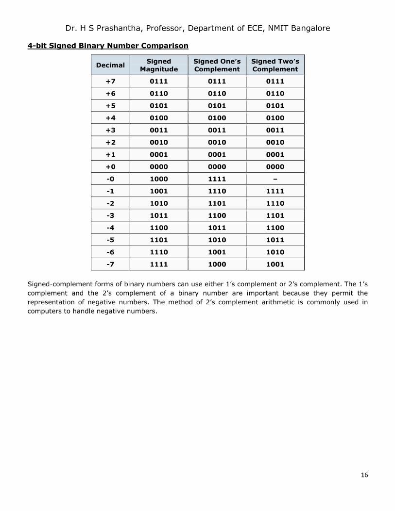
4-bit Signed Binary Number Comparison
Decimal Signed
Magnitude
Signed One’s
Complement
Signed Two’s
Complement
+7 0111 0111 0111
+6 0110 0110 0110
+5 0101 0101 0101
+4 0100 0100 0100
+3 0011 0011 0011
+2 0010 0010 0010
+1 0001 0001 0001
+0 0000 0000 0000
-0 1000 1111 –
-1 1001 1110 1111
-2 1010 1101 1110
-3 1011 1100 1101
-4 1100 1011 1100
-5 1101 1010 1011
-6 1110 1001 1010
-7 1111 1000 1001
Signed-complement forms of binary numbers can use either 1’s complement or 2’s complement. The 1’s
complement and the 2’s complement of a binary number are important because they permit the
representation of negative numbers. The method of 2’s complement arithmetic is commonly used in
computers to handle negative numbers.
Page 17
Dr. H S Prashantha, Professor, Department of ECE, NMIT Bangalore
17
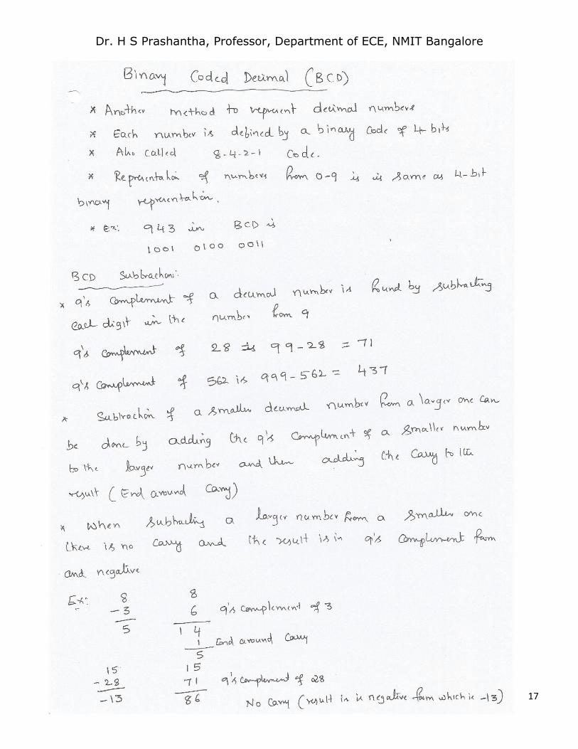
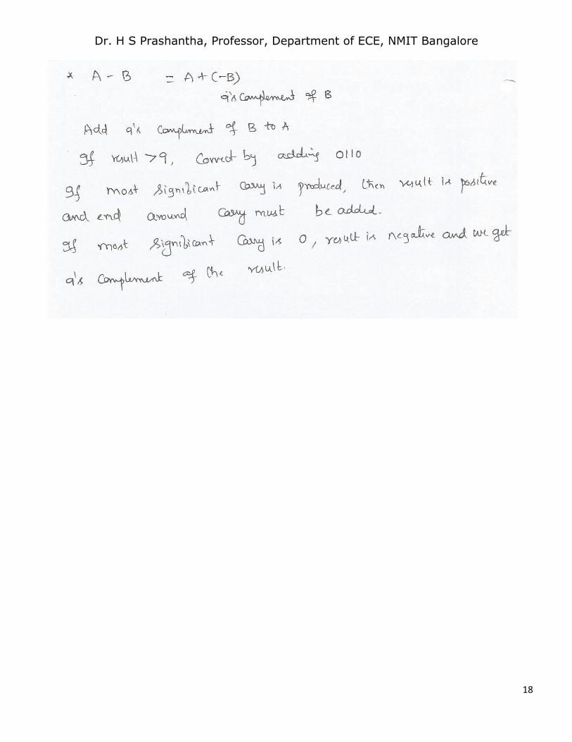
Page 18
Dr. H S Prashantha, Professor, Department of ECE, NMIT Bangalore
18
Page 19
Dr. H S Prashantha, Professor, Department of ECE, NMIT Bangalore
19
DIGITAL LOGIC
Boolean Algebra
Logic Gates
Introduction to Combinational Logic : Half Adder, Full adder
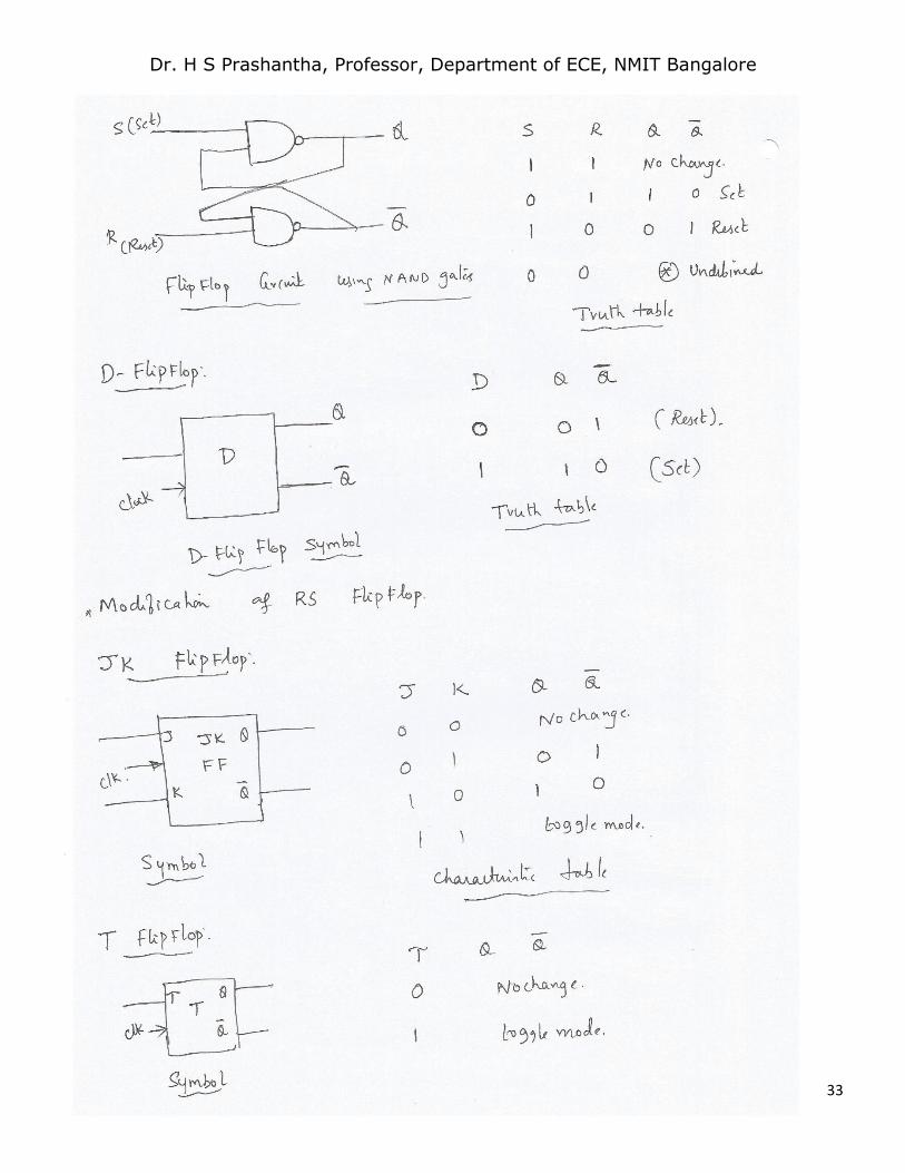
Introduction to Sequential circuits : Flip Flops ( RS FF , JK FF, D FF , T FF ) (only truth table)
Introduction to Boolean
In 1854, George Boole performed an investigation into the “laws of thought” which were based on a
simplified version of the “group” or “set” theory, and from this Boolean or “Switching” algebra was
developed. Boolean algebra deals mainly with the theory that both logic and set operations are either
“TRUE” or “FALSE” but not both at the same time.
For example, A + A = A and not 2A as it would be in normal algebra. Boolean Algebra is a simple and
effective way of representing the switching action of standard Logic Gates and the basic logic statements
which concern us here are given by the logic gate operations of the AND, the OR and the NOT gate
functions.
As well as a standard Boolean Expression, the input and output information of any Logic Gate or circuit
can be plotted into a standard table to give a visual representation of the switching function of the system.
The table used to represent the Boolean expression of a logic gate function is commonly called a Truth
Table. A logic gate truth table shows each possible input combination to the gate or circuit with the
resultant output depending upon the combination of these input(s).
Logic Gate Truth Tables
For example, consider a single 2-input logic circuit with input variables labeled as A and B. There are
“four” possible input combinations or 22 of “OFF” and “ON” for the two inputs. However, when dealing
with Boolean expressions and especially logic gate truth tables, we do not general use “ON” or “OFF” but
instead give them bit values which represent a logic level “1” or a logic level “0” respectively.
Then the four possible combinations of A and B for a 2-input logic gate is given as:
Input Combination 1. – “OFF” – “OFF” or ( 0, 0 )
Input Combination 2. – “OFF” – “ON” or ( 0, 1 )
Input Combination 3. – “ON” – “OFF” or ( 1, 0 )
Input Combination 4. – “ON” – “ON” or ( 1, 1 )
Therefore, a 3-input logic circuit would have 8 possible input combinations or 23 and a 4-input logic circuit
would have 16 or 24, and so on as the number of inputs increases. Then a logic circuit with “n” number
of inputs would have 2n possible input combinations of both “OFF” and “ON”. In order to keep things
simple to understand, we will only deal with simple 2-input logic gates, but the principals are still the
same for gates with more inputs.
The logical AND Function
The Logic AND Function function states that two or more events must occur together and at the same
time for an output action to occur. The order in which these actions occur is unimportant as it does not
Page 20
Dr. H S Prashantha, Professor, Department of ECE, NMIT Bangalore
20
affect the final result. For example, A & B = B & A. In Boolean algebra the Logic AND Function follows
the Commutative Law which allows a change in position of either variable.
The AND function is represented in electronics by the dot or full stop symbol ( . ) Thus a 2-input (A B)
AND Gate has an output term represented by the Boolean expression A.B or just AB.
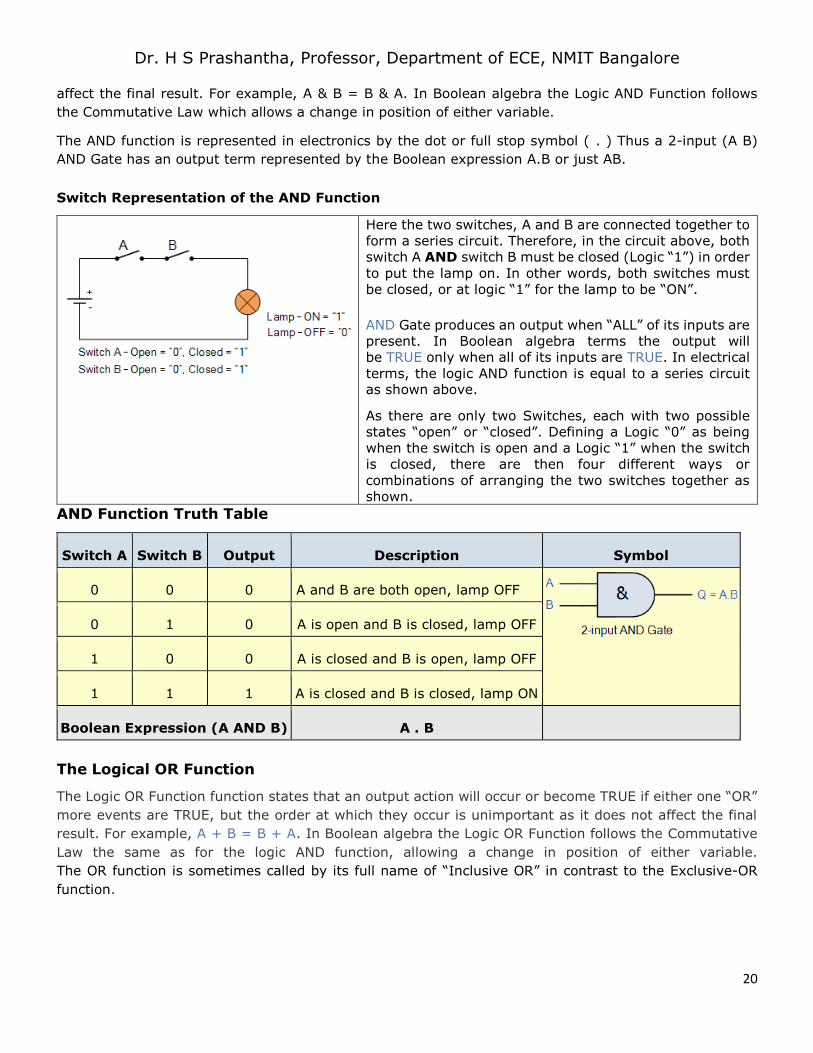
Switch Representation of the AND Function
Here the two switches, A and B are connected together to
form a series circuit. Therefore, in the circuit above, both
switch A AND switch B must be closed (Logic “1”) in order
to put the lamp on. In other words, both switches must
be closed, or at logic “1” for the lamp to be “ON”.
AND Gate produces an output when “ALL” of its inputs are
present. In Boolean algebra terms the output will
be TRUE only when all of its inputs are TRUE. In electrical
terms, the logic AND function is equal to a series circuit as shown above.
As there are only two Switches, each with two possible
states “open” or “closed”. Defining a Logic “0” as being
when the switch is open and a Logic “1” when the switch
is closed, there are then four different ways or
combinations of arranging the two switches together as
shown.
AND Function Truth Table
Switch A Switch B Output Description Symbol
0 0 0 A and B are both open, lamp OFF
0 1 0 A is open and B is closed, lamp OFF
1 0 0 A is closed and B is open, lamp OFF
1 1 1 A is closed and B is closed, lamp ON
Boolean Expression (A AND B) A . B
The Logical OR Function
The Logic OR Function function states that an output action will occur or become TRUE if either one “OR”
more events are TRUE, but the order at which they occur is unimportant as it does not affect the final
result. For example, A + B = B + A. In Boolean algebra the Logic OR Function follows the Commutative
Law the same as for the logic AND function, allowing a change in position of either variable.
The OR function is sometimes called by its full name of “Inclusive OR” in contrast to the Exclusive-OR
function.
Page 21
Dr. H S Prashantha, Professor, Department of ECE, NMIT Bangalore
21
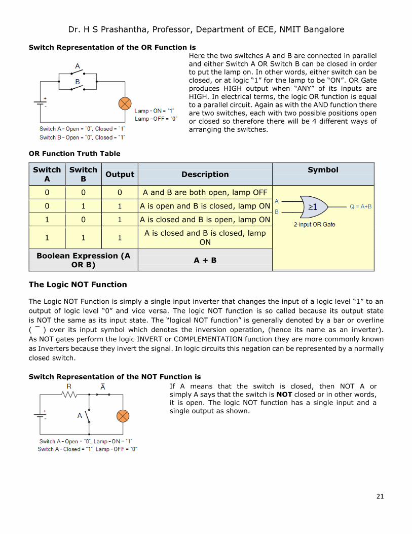
Switch Representation of the OR Function is
Here the two switches A and B are connected in parallel
and either Switch A OR Switch B can be closed in order
to put the lamp on. In other words, either switch can be
closed, or at logic “1” for the lamp to be “ON”. OR Gate
produces HIGH output when “ANY” of its inputs are
HIGH. In electrical terms, the logic OR function is equal
to a parallel circuit. Again as with the AND function there
are two switches, each with two possible positions open
or closed so therefore there will be 4 different ways of
arranging the switches.
OR Function Truth Table
Switch
A
Switch
B Output Description
Symbol
0 0 0 A and B are both open, lamp OFF
0 1 1 A is open and B is closed, lamp ON
1 0 1 A is closed and B is open, lamp ON
1 1 1 A is closed and B is closed, lamp
ON
Boolean Expression (A OR B)
A + B
The Logic NOT Function
The Logic NOT Function is simply a single input inverter that changes the input of a logic level “1” to an
output of logic level “0” and vice versa. The logic NOT function is so called because its output state
is NOT the same as its input state. The “logical NOT function” is generally denoted by a bar or overline
( ¯ ) over its input symbol which denotes the inversion operation, (hence its name as an inverter).
As NOT gates perform the logic INVERT or COMPLEMENTATION function they are more commonly known
as Inverters because they invert the signal. In logic circuits this negation can be represented by a normally
closed switch.
Switch Representation of the NOT Function is
If A means that the switch is closed, then NOT A or
simply A says that the switch is NOT closed or in other words,
it is open. The logic NOT function has a single input and a
single output as shown.
Page 22
Dr. H S Prashantha, Professor, Department of ECE, NMIT Bangalore
22
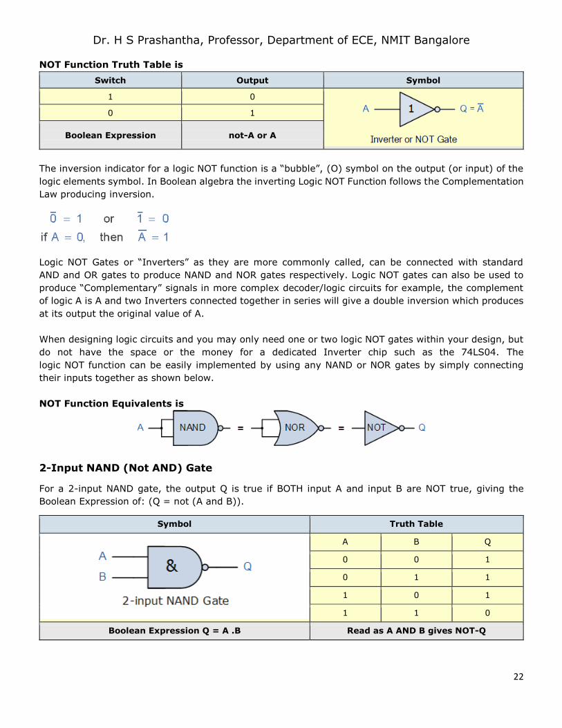
NOT Function Truth Table is
Switch Output Symbol
1 0
0 1
Boolean Expression not-A or A
The inversion indicator for a logic NOT function is a “bubble”, (O) symbol on the output (or input) of the
logic elements symbol. In Boolean algebra the inverting Logic NOT Function follows the Complementation
Law producing inversion.
Logic NOT Gates or “Inverters” as they are more commonly called, can be connected with standard
AND and OR gates to produce NAND and NOR gates respectively. Logic NOT gates can also be used to
produce “Complementary” signals in more complex decoder/logic circuits for example, the complement
of logic A is A and two Inverters connected together in series will give a double inversion which produces
at its output the original value of A.
When designing logic circuits and you may only need one or two logic NOT gates within your design, but
do not have the space or the money for a dedicated Inverter chip such as the 74LS04. The
logic NOT function can be easily implemented by using any NAND or NOR gates by simply connecting
their inputs together as shown below.
NOT Function Equivalents is
2-Input NAND (Not AND) Gate
For a 2-input NAND gate, the output Q is true if BOTH input A and input B are NOT true, giving the
Boolean Expression of: (Q = not (A and B)).
Symbol Truth Table
A B Q
0 0 1
0 1 1
1 0 1
1 1 0
Boolean Expression Q = A .B Read as A AND B gives NOT-Q
Page 23
Dr. H S Prashantha, Professor, Department of ECE, NMIT Bangalore
23
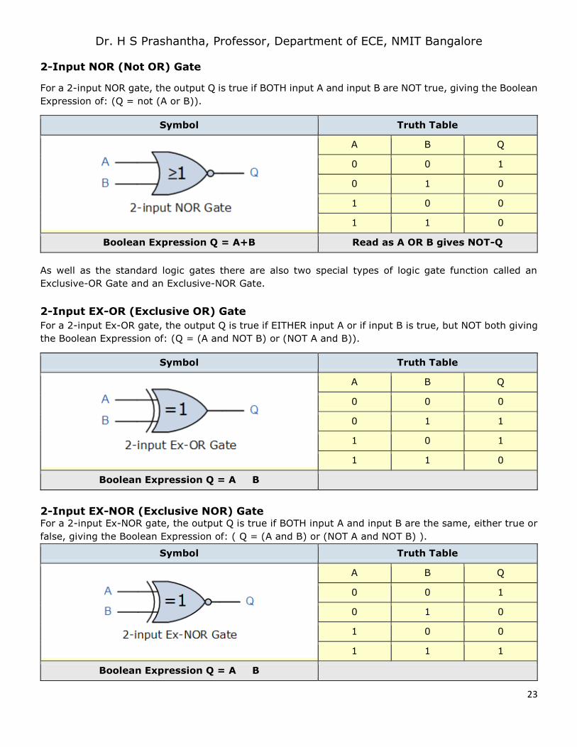
2-Input NOR (Not OR) Gate
For a 2-input NOR gate, the output Q is true if BOTH input A and input B are NOT true, giving the Boolean
Expression of: (Q = not (A or B)).
Symbol Truth Table
A B Q
0 0 1
0 1 0
1 0 0
1 1 0
Boolean Expression Q = A+B Read as A OR B gives NOT-Q
As well as the standard logic gates there are also two special types of logic gate function called an
Exclusive-OR Gate and an Exclusive-NOR Gate.
2-Input EX-OR (Exclusive OR) Gate
For a 2-input Ex-OR gate, the output Q is true if EITHER input A or if input B is true, but NOT both giving
the Boolean Expression of: (Q = (A and NOT B) or (NOT A and B)).
Symbol Truth Table
A B Q
0 0 0
0 1 1
1 0 1
1 1 0
Boolean Expression Q = A B
2-Input EX-NOR (Exclusive NOR) Gate For a 2-input Ex-NOR gate, the output Q is true if BOTH input A and input B are the same, either true or
false, giving the Boolean Expression of: ( Q = (A and B) or (NOT A and NOT B) ).
Symbol Truth Table
A B Q
0 0 1
0 1 0
1 0 0
1 1 1
Boolean Expression Q = A B
Page 24
Dr. H S Prashantha, Professor, Department of ECE, NMIT Bangalore
24
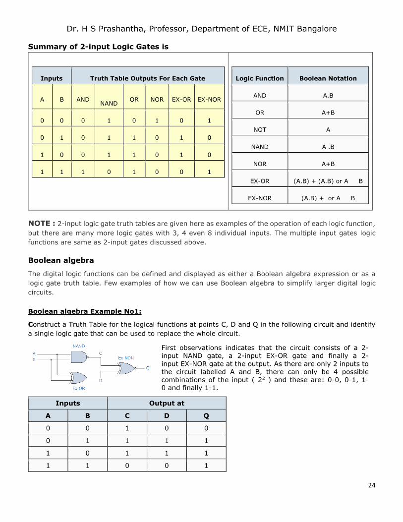
Summary of 2-input Logic Gates is
Inputs Truth Table Outputs For Each Gate
A B AND NAND
OR NOR EX-OR EX-NOR
0 0 0 1 0 1 0 1
0 1 0 1 1 0 1 0
1 0 0 1 1 0 1 0
1 1 1 0 1 0 0 1
Logic Function Boolean Notation
AND A.B
OR A+B
NOT A
NAND A .B
NOR A+B
EX-OR (A.B) + (A.B) or A B
EX-NOR (A.B) + or A B
NOTE : 2-input logic gate truth tables are given here as examples of the operation of each logic function,
but there are many more logic gates with 3, 4 even 8 individual inputs. The multiple input gates logic
functions are same as 2-input gates discussed above.
Boolean algebra
The digital logic functions can be defined and displayed as either a Boolean algebra expression or as a
logic gate truth table. Few examples of how we can use Boolean algebra to simplify larger digital logic
circuits.
Boolean algebra Example No1:
Construct a Truth Table for the logical functions at points C, D and Q in the following circuit and identify
a single logic gate that can be used to replace the whole circuit.
First observations indicates that the circuit consists of a 2-
input NAND gate, a 2-input EX-OR gate and finally a 2-
input EX-NOR gate at the output. As there are only 2 inputs to
the circuit labelled A and B, there can only be 4 possible
combinations of the input ( 22 ) and these are: 0-0, 0-1, 1-0 and finally 1-1.
Inputs Output at
A B C D Q
0 0 1 0 0
0 1 1 1 1
1 0 1 1 1
1 1 0 0 1
Page 25
Dr. H S Prashantha, Professor, Department of ECE, NMIT Bangalore
25
From the truth table above, column C represents the output function generated by the NAND gate, while
column D represents the output function from the Ex-OR gate. Both of these two output expressions then
become the input condition for the Ex-NOR gate at the output.
It can be seen from the truth table that an output at Q is present when any of the two inputs A or Bare
at logic 1. The only truth table that satisfies this condition is that of an OR Gate. Therefore, the whole of
the above circuit can be replaced by just one single 2-input OR Gate.
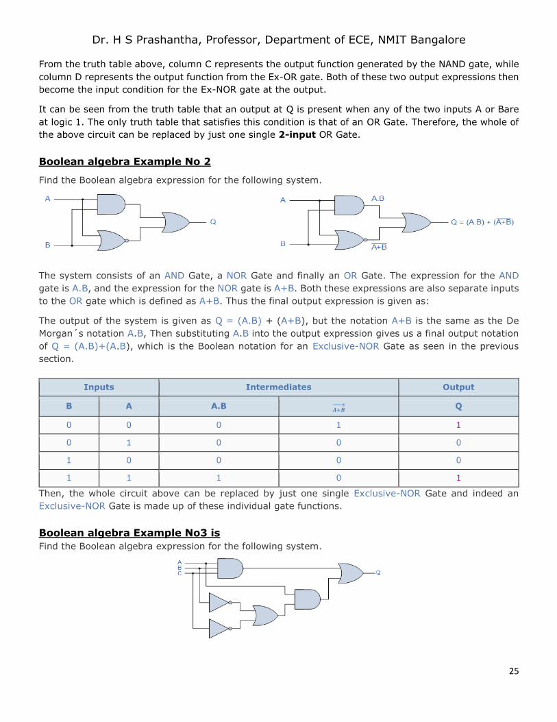
Boolean algebra Example No 2
Find the Boolean algebra expression for the following system.
The system consists of an AND Gate, a NOR Gate and finally an OR Gate. The expression for the AND
gate is A.B, and the expression for the NOR gate is A+B. Both these expressions are also separate inputs
to the OR gate which is defined as A+B. Thus the final output expression is given as:
The output of the system is given as Q = (A.B) + (A+B), but the notation A+B is the same as the De
Morgan´s notation A.B, Then substituting A.B into the output expression gives us a final output notation
of Q = (A.B)+(A.B), which is the Boolean notation for an Exclusive-NOR Gate as seen in the previous
section.
Inputs Intermediates Output
B A A.B 𝑨+𝑩→ Q
0 0 0 1 1
0 1 0 0 0
1 0 0 0 0
1 1 1 0 1
Then, the whole circuit above can be replaced by just one single Exclusive-NOR Gate and indeed an
Exclusive-NOR Gate is made up of these individual gate functions.
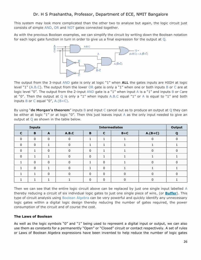
Boolean algebra Example No3 is
Find the Boolean algebra expression for the following system.
Page 26
Dr. H S Prashantha, Professor, Department of ECE, NMIT Bangalore
26
This system may look more complicated than the other two to analyse but again, the logic circuit just
consists of simple AND, OR and NOT gates connected together.
As with the previous Boolean examples, we can simplify the circuit by writing down the Boolean notation
for each logic gate function in turn in order to give us a final expression for the output at Q.
The output from the 3-input AND gate is only at logic “1” when ALL the gates inputs are HIGH at logic
level “1” (A.B.C). The output from the lower OR gate is only a “1” when one or both inputs B or C are at
logic level “0”. The output from the 2-input AND gate is a “1” when input A is a “1” and inputs B or Care
at “0”. Then the output at Q is only a “1” when inputs A.B.C equal “1” or A is equal to “1” and both
inputs B or C equal “0”, A.(B+C).
By using “de Morgan’s theorem” inputs B and input C cancel out as to produce an output at Q they can
be either at logic “1” or at logic “0”. Then this just leaves input A as the only input needed to give an
output at Q as shown in the table below.
Inputs Intermediates Output
C B A A.B.C B C B+C A.(B+C) Q
0 0 0 0 1 1 1 0 0
0 0 1 0 1 1 1 1 1
0 1 0 0 0 1 1 0 0
0 1 1 0 0 1 1 1 1
1 0 0 0 1 0 1 0 0
1 0 1 0 1 0 1 1 1
1 1 0 0 0 0 0 0 0
1 1 1 1 0 0 0 0 1
Then we can see that the entire logic circuit above can be replaced by just one single input labelled A
thereby reducing a circuit of six individual logic gates to just one single piece of wire, (or Buffer). This
type of circuit analysis using Boolean Algebra can be very powerful and quickly identify any unnecessary
logic gates within a digital logic design thereby reducing the number of gates required, the power
consumption of the circuit and of course the cost.
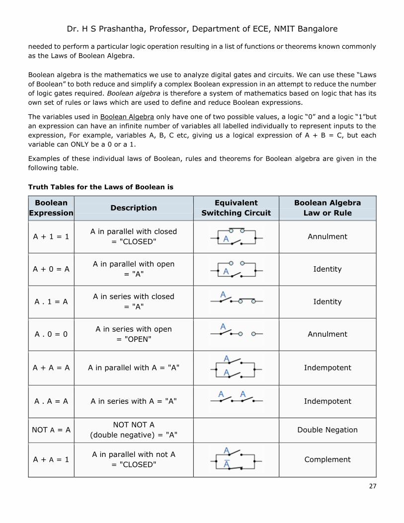
The Laws of Boolean
As well as the logic symbols “0” and “1” being used to represent a digital input or output, we can also
use them as constants for a permanently “Open” or “Closed” circuit or contact respectively. A set of rules
or Laws of Boolean Algebra expressions have been invented to help reduce the number of logic gates
Page 27
Dr. H S Prashantha, Professor, Department of ECE, NMIT Bangalore
27
needed to perform a particular logic operation resulting in a list of functions or theorems known commonly
as the Laws of Boolean Algebra.
Boolean algebra is the mathematics we use to analyze digital gates and circuits. We can use these “Laws
of Boolean” to both reduce and simplify a complex Boolean expression in an attempt to reduce the number
of logic gates required. Boolean algebra is therefore a system of mathematics based on logic that has its
own set of rules or laws which are used to define and reduce Boolean expressions.
The variables used in Boolean Algebra only have one of two possible values, a logic “0” and a logic “1”but
an expression can have an infinite number of variables all labelled individually to represent inputs to the
expression, For example, variables A, B, C etc, giving us a logical expression of A + B = C, but each
variable can ONLY be a 0 or a 1.
Examples of these individual laws of Boolean, rules and theorems for Boolean algebra are given in the
following table.
Truth Tables for the Laws of Boolean is
Boolean
Expression Description
Equivalent
Switching Circuit
Boolean Algebra
Law or Rule
A + 1 = 1 A in parallel with closed
= "CLOSED"
Annulment
A + 0 = A A in parallel with open
= "A"
Identity
A . 1 = A A in series with closed
= "A"
Identity
A . 0 = 0 A in series with open
= "OPEN"
Annulment
A + A = A A in parallel with A = "A"
Indempotent
A . A = A A in series with A = "A"
Indempotent
NOT A = A NOT NOT A
(double negative) = "A" Double Negation
A + A = 1 A in parallel with not A
= "CLOSED"
Complement
Page 28
Dr. H S Prashantha, Professor, Department of ECE, NMIT Bangalore
28
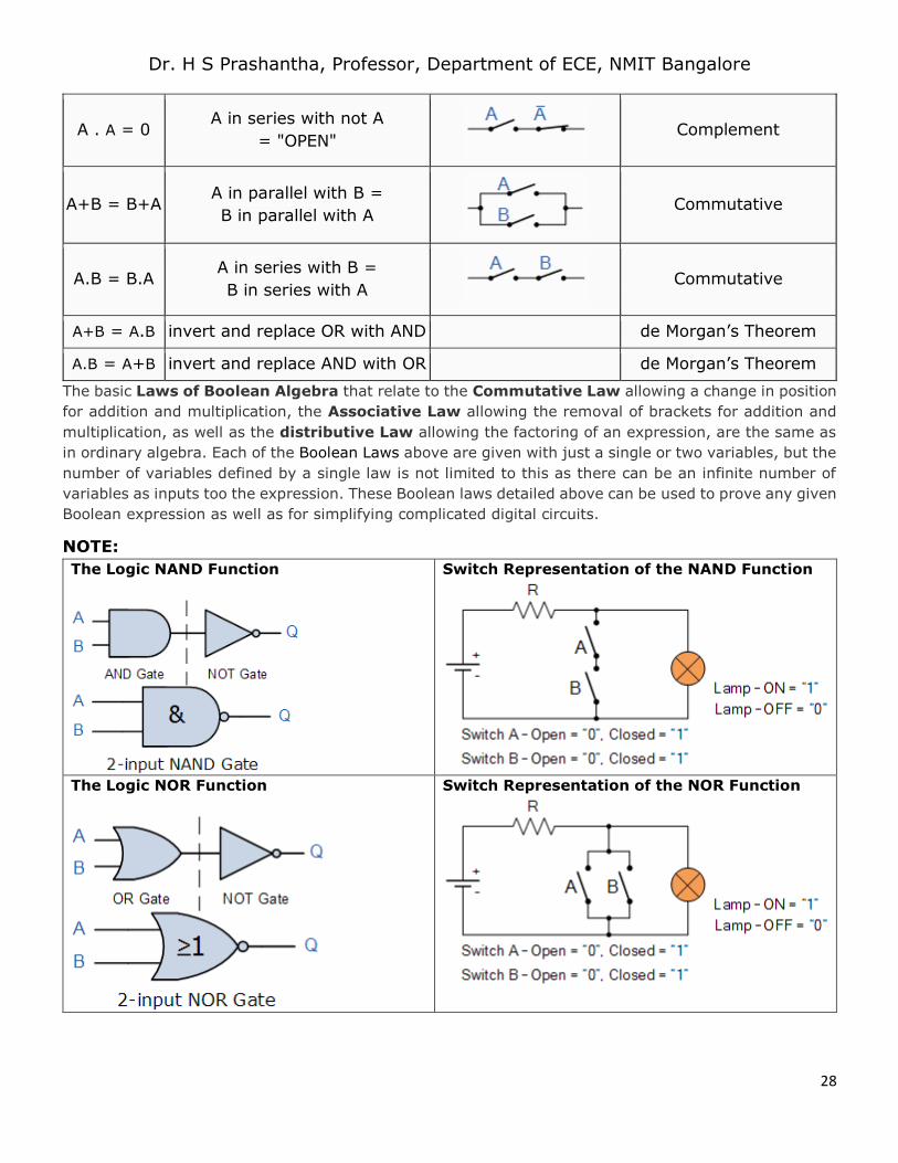
A . A = 0 A in series with not A
= "OPEN"
Complement
A+B = B+A A in parallel with B =
B in parallel with A
Commutative
A.B = B.A A in series with B =
B in series with A
Commutative
A+B = A.B invert and replace OR with AND de Morgan’s Theorem
A.B = A+B invert and replace AND with OR de Morgan’s Theorem
The basic Laws of Boolean Algebra that relate to the Commutative Law allowing a change in position
for addition and multiplication, the Associative Law allowing the removal of brackets for addition and
multiplication, as well as the distributive Law allowing the factoring of an expression, are the same as
in ordinary algebra. Each of the Boolean Laws above are given with just a single or two variables, but the
number of variables defined by a single law is not limited to this as there can be an infinite number of
variables as inputs too the expression. These Boolean laws detailed above can be used to prove any given
Boolean expression as well as for simplifying complicated digital circuits.
NOTE:
The Logic NAND Function
Switch Representation of the NAND Function
The Logic NOR Function
Switch Representation of the NOR Function
Page 29
Dr. H S Prashantha, Professor, Department of ECE, NMIT Bangalore
29
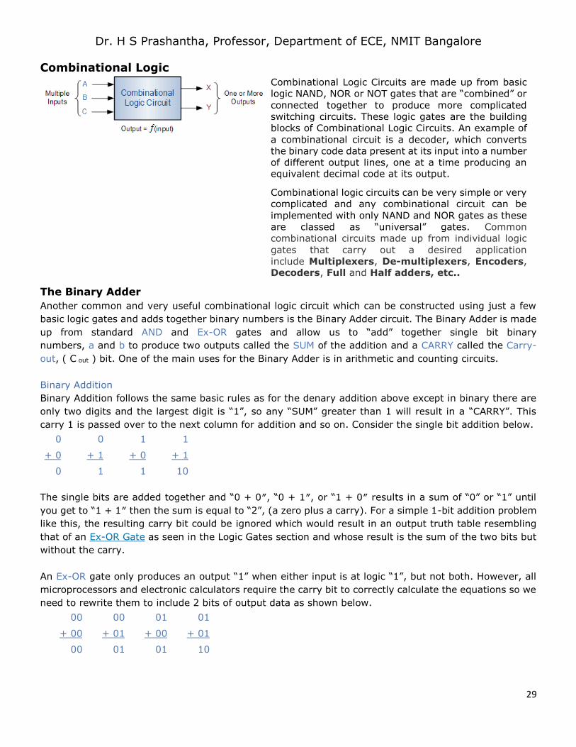
Combinational Logic
Combinational Logic Circuits are made up from basic
logic NAND, NOR or NOT gates that are “combined” or
connected together to produce more complicated
switching circuits. These logic gates are the building
blocks of Combinational Logic Circuits. An example of
a combinational circuit is a decoder, which converts
the binary code data present at its input into a number
of different output lines, one at a time producing an equivalent decimal code at its output.
Combinational logic circuits can be very simple or very
complicated and any combinational circuit can be
implemented with only NAND and NOR gates as these
are classed as “universal” gates. Common
combinational circuits made up from individual logic
gates that carry out a desired application
include Multiplexers, De-multiplexers, Encoders, Decoders, Full and Half adders, etc..
The Binary Adder
Another common and very useful combinational logic circuit which can be constructed using just a few
basic logic gates and adds together binary numbers is the Binary Adder circuit. The Binary Adder is made
up from standard AND and Ex-OR gates and allow us to “add” together single bit binary
numbers, a and b to produce two outputs called the SUM of the addition and a CARRY called the Carry-
out, ( C out ) bit. One of the main uses for the Binary Adder is in arithmetic and counting circuits.
Binary Addition
Binary Addition follows the same basic rules as for the denary addition above except in binary there are
only two digits and the largest digit is “1”, so any “SUM” greater than 1 will result in a “CARRY”. This
carry 1 is passed over to the next column for addition and so on. Consider the single bit addition below.
0 0 1 1
+ 0 + 1 + 0 + 1
0 1 1 10
The single bits are added together and “0 + 0″, “0 + 1″, or “1 + 0″ results in a sum of “0” or “1” until
you get to “1 + 1″ then the sum is equal to “2”, (a zero plus a carry). For a simple 1-bit addition problem
like this, the resulting carry bit could be ignored which would result in an output truth table resembling
that of an Ex-OR Gate as seen in the Logic Gates section and whose result is the sum of the two bits but
without the carry.
An Ex-OR gate only produces an output “1” when either input is at logic “1”, but not both. However, all
microprocessors and electronic calculators require the carry bit to correctly calculate the equations so we
need to rewrite them to include 2 bits of output data as shown below.
00 00 01 01
+ 00 + 01 + 00 + 01
00 01 01 10
Page 30
Dr. H S Prashantha, Professor, Department of ECE, NMIT Bangalore
30
From the above equations we know that an Ex-OR gate will only produce an output “1” when “EITHER”
input is at logic “1”, so we need an additional output to produce a carry output, “1” when “BOTH” inputs
“A” and “B” are at logic “1” and a standard AND Gate fits the bill nicely. By combining the Ex-OR gate
with the AND gate results in a simple digital binary adder circuit known commonly as the “Half Adder”
circuit.
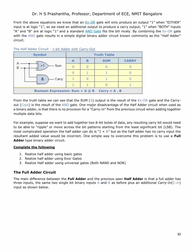
The Half Adder Circuit - 1-bit Adder with Carry-Out
Symbol Truth Table
A B SUM CARRY
0 0 0 0
0 1 1 0
1 0 1 0
1 1 0 1
Boolean Expression: Sum = A ⊕ B Carry = A . B
From the truth table we can see that the SUM (S) output is the result of the Ex-OR gate and the Carry-
out (Cout) is the result of the AND gate. One major disadvantage of the Half Adder circuit when used as
a binary adder, is that there is no provision for a “Carry-in” from the previous circuit when adding together
multiple data bits.
For example, suppose we want to add together two 8-bit bytes of data, any resulting carry bit would need
to be able to “ripple” or move across the bit patterns starting from the least significant bit (LSB). The
most complicated operation the half adder can do is “1 + 1″ but as the half adder has no carry input the
resultant added value would be incorrect. One simple way to overcome this problem is to use a Full
Adder type binary adder circuit.
Complete the following
1. Realize half adder using basic gates
2. Realize half adder using Exor Gates
3. Realize Half adder using universal gates (Both NAND and NOR)
The Full Adder Circuit
The main difference between the Full Adder and the previous seen Half Adder is that a full adder has
three inputs, the same two single bit binary inputs A and B as before plus an additional Carry-In(C-in)
input as shown below.
Page 31
Dr. H S Prashantha, Professor, Department of ECE, NMIT Bangalore
31
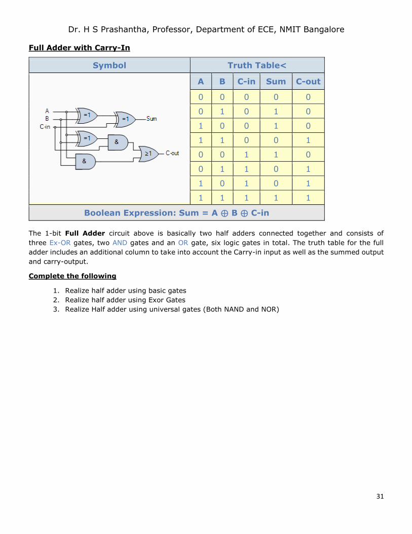
Full Adder with Carry-In
Symbol Truth Table<
A B C-in Sum C-out
0 0 0 0 0
0 1 0 1 0
1 0 0 1 0
1 1 0 0 1
0 0 1 1 0
0 1 1 0 1
1 0 1 0 1
1 1 1 1 1
Boolean Expression: Sum = A ⊕ B ⊕ C-in
The 1-bit Full Adder circuit above is basically two half adders connected together and consists of
three Ex-OR gates, two AND gates and an OR gate, six logic gates in total. The truth table for the full
adder includes an additional column to take into account the Carry-in input as well as the summed output
and carry-output.
Complete the following
1. Realize half adder using basic gates
2. Realize half adder using Exor Gates
3. Realize Half adder using universal gates (Both NAND and NOR)
Page 32
Dr. H S Prashantha, Professor, Department of ECE, NMIT Bangalore
32
Page 33
Dr. H S Prashantha, Professor, Department of ECE, NMIT Bangalore
33