
l l l l l l l l l l l l l l l l l l i
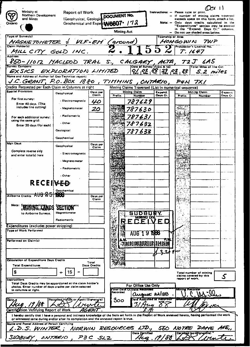
41IMNWMM 2.11552 MONGOWIN 010
GEOPHYSICAL REPORT
ON THE
McMillan Gold Mine Propertij r r C l W C T\Mongowin Township ** c ̂ s
Sudbury Mining District nOntario, Canada AUG ̂
Mill c^oold I NC. MINING UNOS SECTION
Prepared by:3. C. GrantExsics Exploration Ltd.August ,1988
l l l
l
l
010C
TABLE OF CONTENTS
Page
l SUMMARY. . .. . . . . . . . . . . . . . . . . . . . . l
INTRODUCTION. . . . . . . . . . . .. . . . . . . . . . 3
l LOCATION AND ACCESS. . . . . . . . , . . . . . . . . . 3
PERSONNEL . . . . . . . . . . . . . . . . . . . . . . k
CLAIM GROUP. . . . . . . . . . . . . . . . . . . . . . 5
l GEOLOGY. . . . . . .. . . . . . . . . . . . . . . . . 7
SURVEY RESULTS. . . . . . . . . . . . . . . . . . . . 11
l RECOMMENDATIONS AND CONCLUSIONS . . . . . . . . . . . 17
REFERENCES. . . . . . . . . . . . . . . . . . . . . ..20
LIST OF FIGURES
l Figure l Location Map
Figure 2 Claim Group
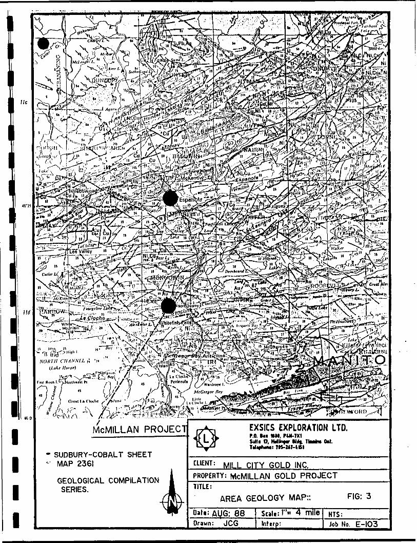
p Figure 3 Area Geology Map
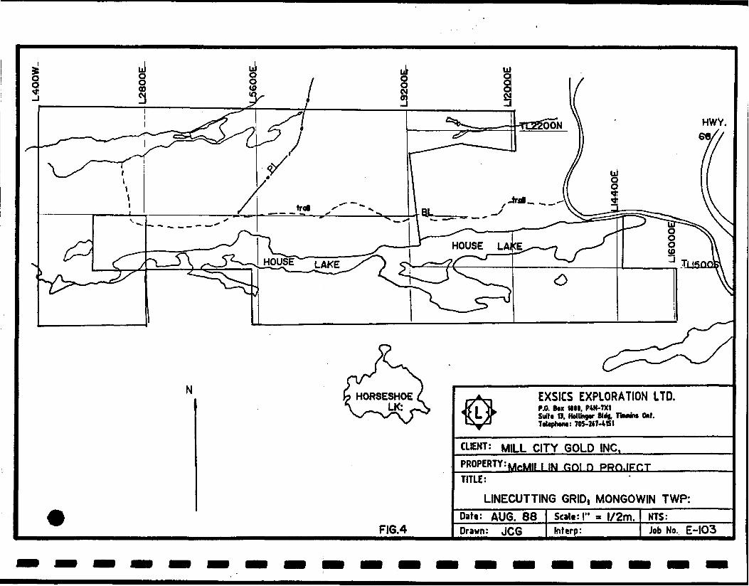
M Figure k L ine Cutting Grid, Mongowin Township
l LIST OF MAPS IN BACK POCKET
MAP NO. l Contoured Magnetometer Survey
l MAP NO. 2 VLF Dip Angle
APPENDICES
* Appendix A EDA OMNI PLUS Magnetometer System
l
l
l
l
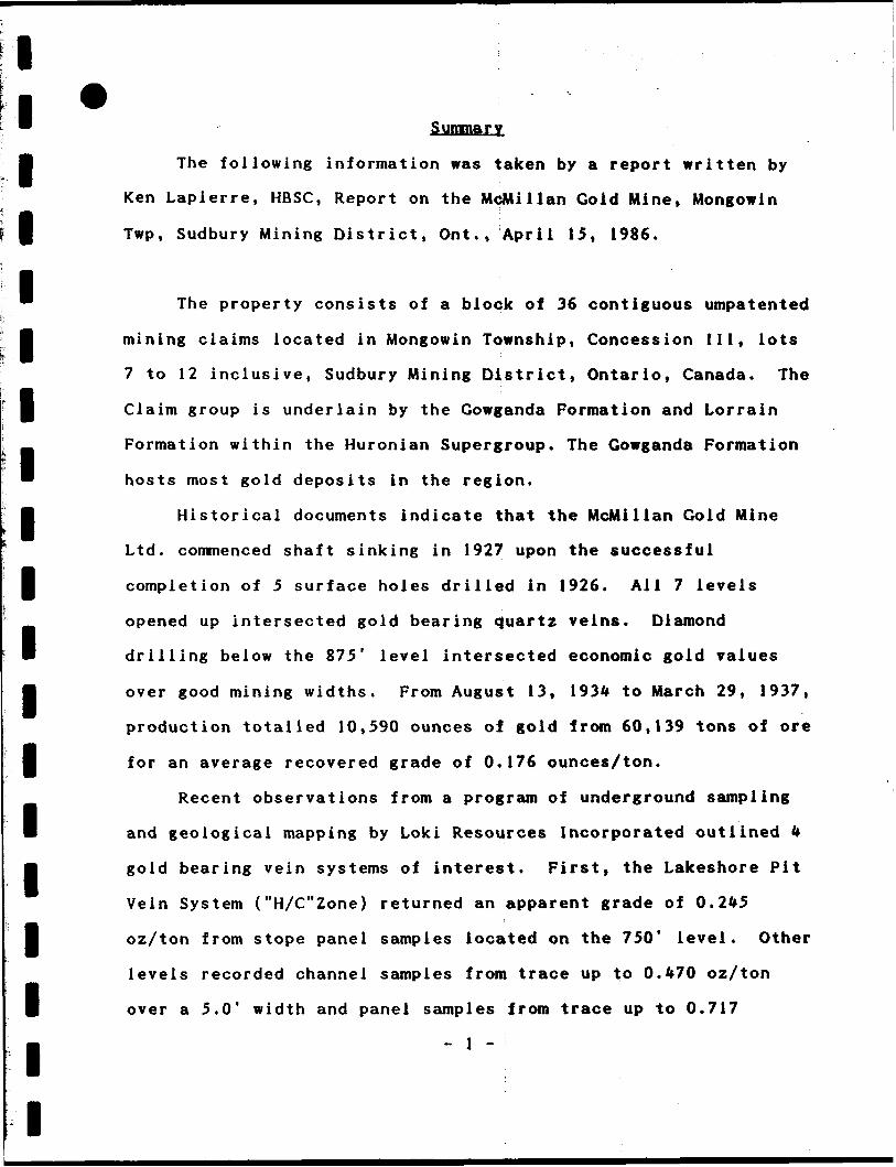
l Summary
B The following information was taken by a report written by
l
l
l
Ken Lapierre, HBSC, Report on the McMillan Gold Mine, Mongowin
Twp, Sudbury Mining District, Ont., April 15, 1986.
" The property consists of a block of 36 contiguous umpatented
l mining claims located in Mongowin Township, Concession III, lots
7 to 12 inclusive, Sudbury Mining District, Ontario, Canada. The
P Claim group is underlain by the Gowganda Formation and Lorrain
Formation within the Huronian Supergroup. The Gowganda Formation
* hosts most gold deposits in the region.
B Historical documents indicate that the McMillan Gold Mine
Ltd. commenced shaft sinking in 1927 upon the successful
l completion of 5 surface holes drilled in 1926. All 7 levels
opened up intersected gold bearing quartz veins. Diamond
B drilling below the 875' level intersected economic gold values
B over good mining widths. From August 13, 1934 to March 29, 1937,
production totalled 10,590 ounces of gold from 60,139 tons of ore
l for an average recovered grade of 0.176 ounces/ton.
Recent observations from a program of underground sampling
B and geological mapping by Loki Resources Incorporated outlined k
m gold bearing vein systems of interest. First, the Lakeshore Pit
Vein System ("HXC"Zone) returned an apparent grade of 0.245
l oz/ton from stope panel samples located on the 750' level. Other
levels recorded channel samples from trace up to 0.470 oz/ton
l over a 5.0' width and panel samples from trace up to 0.717
- l -

loz/ton. Secondly, the Fault/Shear Zone System ("D Zone )
l returned an average grade of 0.328 oz/ton over a 3.2' width and
an undetermined length from the 525* and 625* levels. Thirdly,
8 the " 3" Zone Structure located on the 525' level, of this zone
m graded 0.203 oz/ton over a 3.8' width. Panel samples returned
gold values from trace up to 1.44 oz/ton. Fourthly, Pit 9 2 Vein
l System returned no gold values of economic importance.
Geological observations indicate that most gold bearing vein
l systems are associated with fault/shear zone environments and at
M pelite/quartzite contacts. The main "H/C" Zone appears to
terminate against the northeast trending Fault/Shear Zone System,
l Its faulted extension may be the "3" Zone Structure.
l
l
l
l
l
l
l
l
l
l
- 2 -

l™
l ntroduction
fl A program of linecutting, Magnetometer survey and VLF-EM
Survey was carried out on a group of 36 contiguous, unpatented
l mining claims in Mongowin Township for Mill City Gold Inc. The
g work was done jointly by Alquest Exploration Services and Exsics
Exploration Limited, Timmins, Ontario, on a contract basis.
l The purpose of the program was to detect and deliniate any
conductive features such as shear and fault zones which would
g respond to the relatively high frequency VLF technique. The
^ magnetic survey was designed to yield a high resolution plan of
' the magnetic susceptability which would aid in both structural
l and geological interpretation of the property.
This report then will deal with the survey procedures,
l results and interpretation of the program.
Reference is made to the property geology but a detailed
B correlation with the survey results will be done at a later date.
l
l l l l l l l
Location
The property is located in Mongowin Township, Concession
III, in all parts of lots 7-12 inclusive, Sudbury Mining Division,
Ontario at 46 degrees, 08 minutes north latitude, 81 degrees, 45
minutes longitude in the Township.
More specifically, Mongowin Township is located
approximately 16 km southwest of Espanola and 75 km southwest of
the City of Sudbury, (refer to figures l Ac 2 of this report)
- 3 -

l
l
l
l
l
l
ll
ll
l
l
l
l
l
l
l
l
l
i i
QUEBEC
tMMMAfUN
•T1AWA
EXSICS EXPLORATION LTD,P.O. tot MM,fcf^P. H****
CLIENT: MILL CITY GOLD INC.PROPERTY: McMILLAN GOLD PROJECTTITLE:
LOCATION HAP
Daft: Aug. 1968Drawn:
Sclit: l"* 12SmlliiInfcrp:
Ftl. 1NTS:Job Ho.EE-103

lAccess
l Access to the property is west from Sudbury for 68 km along
Highway #17, then south on Highway #6 for 20 km (through
l Espanola) to the waste disposal site turn off located on the
m west side of the highway. A bushroad then leads north for 1,000
feet, then proceeds k km west to the center of the claim group,
l House Lake and the McMiilan minesite area, (figure 2)
l Personnel
H The following people were directly involved with the project
during January and February, 1988,
l Dan Rifou Geophysical Operator Sturgeon Palls, Ont.
John Penttinen Geophysical Operator Timmins, Ont.
l
l
l
l
l
l
l
l
l
Steve Anderson Geophysical Operator Timmins, Ont.
The work was supervised by both 3.C. Grant it R.J.Meikle of
Exsics.
- k -
l l l l l l l l l l l l l l l l l l l
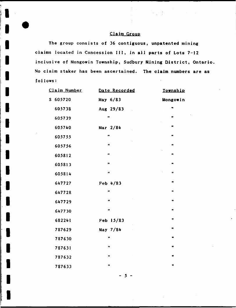
Claim Group
The group consists of 36 contiguous, unpatented mining
claims located in Concession III, in all parts of Lots 7-12
inclusive of Mongowin Township, Sudbury Mining District, Ontario.
No claim staker has been ascertained. The claim numbers are as
follows:
Date Recorded Township
May 6/83 Mongowin
Claim Number
S 605720
605738
605739
605740
605755
605756
605812
605813
605814
647727
647728
6*7729
647730
682241
787629
787630
787631
787632
787633
Aug 29/83
Mar 2/84
Feb 4/83
Feb 15/83
May 7/84
- 5 -
l l l l l l
l l l
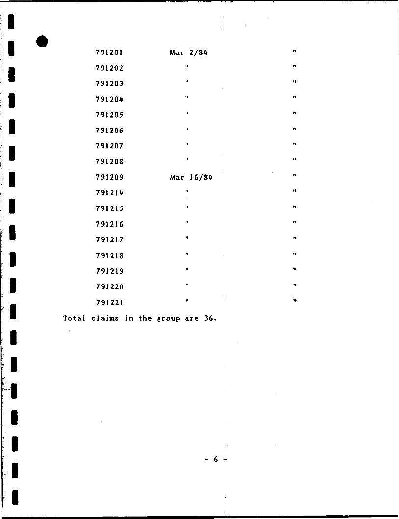
791201 Mar
791202
791203
791204
791205
791206
791207
791208
l 791209 Mar 16/84
791214
l 791215
791216
791217
791218
791219
791220
m 791221
Total claims in the group are 36.
l
l
l
l
l
l
l
- 6 -

HORSESHO AKE
EXSICS EXPLORATION LTDP.O. M* NM. WM-7X1 Suitt O. HriUnftr Md* ThMhw (M
: 7IS-I47-415I
CLIENT: MILL CITY GOLD INC.
PROPERTY: MCMILLAN GOLD PROJECT
CLAIM GROUP
MONGOWIN TOWNSHIPScale:r fa!IX2 m
Job No. F-IO3
l l Geology
B The following "Regional Geology" and "Local Geology" are
taken from a report on the property by Ken Lapierre HBSC, dated
f April 15/1986 titled "Report on the McMilian Cold Mine, Mongowin
— Township,Sudbury Mining District, Ontario."
' A) Regional Geology
H The geology of the Whitefish Palis and Espanola area consist
predominately of Precambrian (Proterozoic) metasedimentary rocks
l that were later covered partially by unconsolidated Cenozoic
deposits. The Precambrian rocks represent a 29,000 foot thick
l series of metasediments known as the Huronian Supergroup. This
B series of rocks are divided into k g roups based on their cyclic
evolution. Prom oldest to youngest the k groups are: Elliot Lake
l Group, Hough Lake Group, Quirke Lake Group and Cobalt Group. Each
group generally represents a cyclic repitition of conglomerates,
l argillite(pelite) and sandstone(quartzite).
m The Huronian Supergroup metasedimentary units were then
intruded by sill-like bodies of Nipissing diabase, amphibolite
l
l
l
l
dikes, ultramafic to granitic plutons then finally post tectonic
diabase intrusions.
Structurally, the area lies within the Penokean fold belt of
the Southern Province within the Canadian Shield. At least 3
series of deformational-metamorphic events altered the rocks in
l the region; 1) major east-west trending folds, 2) moderate east-
west to northeast trending folds, 3) minor northwest to northeast
trending folds.
Ile
46'IS
//rf
l l l l l
460
V H s ''l Afr64T.iV; \is!l V-cv'i. t ,i.Y\ (iMcl^fl..' \.^.\S s
, \ f ̂ ^Vi'V^r/.V 5. "vV 7 -L,:. * \Suthr
MCMILLAN PROJECT]
- SUDBURY-COBALT SHEET 4 ' MAP 2361
GEOLOGICAL COMPILATION SERIES.
m EXSICS EXPLORATION LTD.P.O. 1*1 *M. f WI-7X1 JUfi O. tWUnftr H**
}IS-247-(Bt(M.
CLIENT; M [LL C| TY GOLD INC.
PROPERTY: MCMILLAN GOLD PROJECT
TITLE:
AREA GEOLOGY MAP:: FIG: 3
: AUG: 88Drawn: JCG
Scad: l"* 4 mileInftrp:
NTS:
Job No. E-103
N
FI6.4
HWY.
EXSICS EXPLORATION LTDP.O. BM 1000. P4M-7X1Suit* O. Helling Kit. TkMfcw Out.TtUphww: 705-2(7-461
CLIENT: MILL CITY GOLD INC.PROPERTY -MeMIL t tM HTITLE:
LINECUTTING GRID, MONGOWIN TWP:
: AUG. 88Drawn; JCG
Scalt: l" . I72m.Inferp:
NTS:Job No. E-103
lllllllllllllllllll
Stratigraphic displacement of rock types range from tens of
feet up to thousands of feet. Location of fault zones generally
represent boundaries between structural domains. Faulting took
place before, during and after the deformational-metamorphic
events. At least 3 fault systems occur in the region; 1) major
east-west trending faults possibly related to major east-west
trending folds,2) northeast trending faults, 3) northwest
trending faults.
Regionally, the Gowganda Formation hosts the environment for
the accumulation of gold bearing fluids. Research indicates that
gold is associated with structurally and stratigraphically
controlled environments.
B) Local Geology
The geology of the claim group consist predominantly of
Gowganda and Lorrain Formation metasediments of the Cobalt Croup
within the Huronian Supergroup. The north and central claims are
underlain by rocks of the Gowganda Formation. These rocks are
steeply dipping east-west trending conglomerates and alternating
bands of pelite and quartzite. The southern claims are underlain
by rocks of the Lorrain Formation. These rocks are steeply
dipping east-west trending impure quartzites that form the ridges
south of House Lake.
Several diabase and amphibolite intrusions cross-cut all
rocks of the claim group. Structurally, the metasediments form
the limb connecting the LaCloche syncline to the south with the
Fox Lake anticline to the north.
- 8 -
l l
Gold ore at the McMillan property has generally been
g accepted as originating from a major anticlinal fold, trending
— northeast and plunging at 65 degrees. This mine fold is located
™ east of the shaft under House Lake. The gold bearing quartz
l veins are apparently associated within and at the contacts of
folded quartzite and pelite units in close proximity to diabase
J sills and dikes. Gold occurs in this native state and intimately
—. associated with arseno-pyr i te, pyrite, pyrrhotite and
™ chalcopyrite.
l Survey Parameters
Magnetometer Survey
l A total of 40 miles were surveyed using the proton
precession method measuring the Earth's total magnetic field.
B The results, corrected for diurnal variation, were plotted in
B plan form and contoured to outline trends of lower and higher
magnetic susceptibility. The survey was carried out using the
l following parameters:
Instrument: EDA Instruments OMNI Plus-Portable proton Precession
B Magnetometer
B EDA Instrument OMNI IV recording base station
Sensistivi ty : *Y~ I nano tesla
l Parameters Measured: Earth's total mangetic field
in nano-teslas.
l Diurnal Correction Method: Compatible recording
m base station using a sample interval of 30 seconds.
Reading interval: 100 feet
l
l
- 9 -
l l Contour interval: 100 nano-teslas
8 Data Presentation: Plan, Contoured EM, Scale-l"-200
Map l -Sheet l
l VLF-EM Survey
M The VLF method is a high frequency (relatively) EM technique
™ which employs the use of VLF transmitting stations which operate
l world wide for submarine communications. The magnetic field
generated from these vertical antenas is horizontal and
J concentric. This primary field will induce a secondary field in
any conductor properly coupled with the station direction. The
VLF-EM method measures the vertical component of the secondary
field. Therefore a station should be chosen which is on strike
—
*
B
with the expected strike of the conductor one is searching for.
l This is called Maximum Coupling and in reality stations up to 45
degrees off strike can be used. Because of the high frequency of
™ this method, weak conductive features will be decteted, including
B some overburden features.
Therefore, interpretation of VLF data should be done
l discr iminately and used in conjunction with other methods. Under
some circunstances structural interpretation can be ascertained
B
l l l l l
if some knowledge of the bedrock is available.
The VLF-EM survey was carried out using the following
parameters:
Instrument EDA OMNI Plus, VLF Receiver
Transmitter Station-Cutler Maine (NAA)
Parameter Measured-In-Phase Dip Angles
- 10 -

l l
Frequency -24.0 Khz
g Direction to Station-115 degrees True North
0 All readings taken facing-North
* Data Presentation - Plan Form: Dip Angles
l Scale -- 1 "-200'
Profile Scale: l 011=20**
l* Survey Results
* The magnetometer and VLF-EM surveys were successful in
M outlining numerous east-west trending conductive and magnetic
anomalies. Some of the EM targets have coincident magnetic
l responses while others show little to no magnetic signature.
Most probably, some of the zones may be caused by surficial
™ causes such as conductive overburden. Others may also be caused
B by creek and lake systems or swamp contacts.
The conductors have been labelled and will be discused
l separately and in alphabetical order throughout this report.
There are numerous, weaker, sub-parallel zones which have
m not been discussed or interpreted at this time.
l
l
l
l
l
l
-11-

l" Concuctor A
l This zone represents a long formations! type conductor
striking in an east-northeast-east direction from Line 400W/900N
l to L9600E/2375N.
— The zone appears to be contained in a swampy marsh-type
™ environment which may relate to a fault structure and contact
B zone between the Gowganda Formation and Quirke Lake Group (refer
to Map 2361, Sudbury-Cobal t Sheet, Geological Compilation Series,
f \ "-k miles).
— The magnetics for this feature were typical to the type of
™ responses noted with fault structures and or contact zones. The
B magnetics show direct to flanking correlation all along the zones
strike length.
l Conductor B
This zone is also representative of a long formational type
B
l
l
response closely parallelling the strike of zone A. This feature
strikes from L4800E/1500N to L1200E/2600N where it continues offm
the grid to the northeast.
l The magnetics show direct correlation with sections of the
zone all along its strike length.
l Another explanation of B may show that this zone actually
m t erminates on line 9600E/1800N and that section of the zone
between lines 10000E to 12000E may in fact be on extension of
l Zone A which has been faulted or sheared and shifted south.
Zone B may relate to a legitimate bedrock response possible
graphitic horizons or sulphide lenses within the sediments.
- 12 -
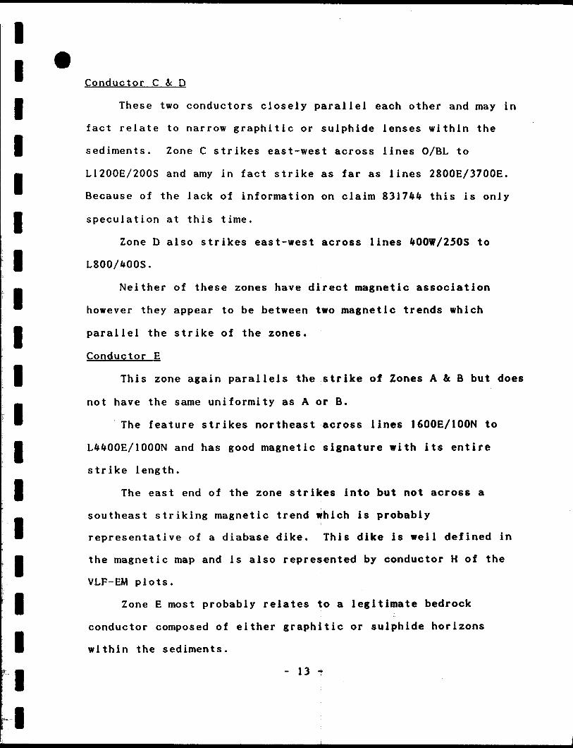
lConductor C 3c D
l These two conductors closely parallel each other and may in
fact relate to narrow graphitic or sulphide lenses within the
l sediments. Zone C strikes east-west across lines 0/BL to
. L1200E/200S and amy in fact strike as far as lines 2800E/3700E.
™ Because of the lack of information on claim 8317*4 this is only
l speculation at this time.
Zone D also strikes east-west across lines 400W/250S to
l L800AOOS.
. Neither of these zones have direct magnetic association
— however they appear to be between two magnetic trends which
l parallel the strike of the zones.
Conductor E
g This zone again parallels the strike of Zones A A B but does
— not have the same uniformity as A or B.
" The feature strikes northeast across lines 1600E/100N to
l L4400E/1000N and has good magnetic signature with its entire
strike length.
J The east end of the zone strikes into but not across a
— southeast striking magnetic trend which is probably
™ representative of a diabase dike. This dike is well defined in
B the magnetic map and is also represented by conductor H of the
VLF-EM plots.
l Zone E most probably relates to a legitimate bedrock
conductor composed of either graphitic or sulphide horizons
l
l
within the sediments.
- 13 -r

l l l l l
l l l
Conductor F
This structure is somewhat weaker on its west extension but
is becoming quite strong as it strikes east into claim 831144.
The zone, although spotty, probably strikes from LO/1400S to
L1200E/1000S. There is no direct magnetic association with this
feature
Conductor G
Zone G is also a weak, questionable source at this time. It
l may in fact relate to weak cross structure of unknown
compos!t ion.
l The zone strikes southeast across lines3200EX100N to
m 4400E/600S. There is no magnetic correlation with the feature
where the east extension strikes up to but not into a moderate
l high feature.
Conductor H
l As stated earlier, this feature appears to relate to a
m d iabase dike feature striking southeast across lines 5000E/500N
™ to 7600E/600S. This is good magnetic signature with the entire
l feature.
Conductor I
l This feature strikes southeast across lines 56000E/100S to
g 6400E/525S and closely parallels Zone H and the suspected dike.
™ There is a closely, north flanking mag high on line LWOOE/200S
l with the remainder of the zone magnetically quiet.
The zone may be representative of a legitimate bedrock
stringer type zone or the southwest edge of the dike.
- U -
l l l l l l l l l l l l l l l l l i l
Conductor 3
This feature strikes east-west across lines 6800E/650N to
7600E/675N where it appears to divide into two parallel zones
striking across line 9200E/700N and 200N and off of the grid to
the east.
There is no magnetic association with the conductor. The
feature may relate to graphitic lenses within the sediments.
Conductor K
This zone strikes east-west across lines 800E/1650S to
2000E/1850S and has moderate to good magnetic association aiong
its entire strike length.
It may in fact relate to a contact zone between the Gowganda
and Lorrain Formations.
Conductor L
This feature also strikes east-west from lines 400W/2000S to
2800E/2050S and off of the grid to the east. The zone has
moderate to good magnetic signature and may relate to a
legitimate bedrock zone within the contact zone between the above
mentioned two formations.
Conductor M
This feature represents another long formational type
structure striking east-northeast across lines 5600E/1425S to
14400EAOOS and off of the grid to the east. The entire zone is
contained within House Lake and there is good magnetic signature
with all of the strike length.
- 15 -
illlllllllll l l l l l l l
This zone is most significant as it probably relates to the
structure which is hosting the ore for the McMillan mine. K.
Lapierre's report states Gold ore at the McMillan property has
generally been accepted as originating from a major anticlinal
fold, trending northeast and plunging at 65 degrees. This mine
foid is located east of the shaft under House lake. If this
information is accurate, then Zone M becomes the major target
area.
Conductor N
This feature also strikes east-northeast across lines
5600E/2300S to 8800E/1750S. The western extension has no
magnetic correlation, however, the eastern extension strikes into
a good magnetic structure striking into Zone M.
This zone may represent a legitimate bedrock response
possible sulphide lenses or shears within the sediments.
Conductor O
This feature strikes Southeast across lines 9200E/1950S to
11600E/2700S and off of the grid to the southeast. There is some
spotty mag highs with the zone. The strike of this zone may have
been controlled by the presence of the diabase dike coming in to
the northeast across lines 9600E/1600S to 10400E/2050S.
Conductor P
This feature strikes east-southeast across lines
10800E/2175S to 13600E/2550S and off of the grid to the
southeast.
- 16 -
l l l
l l
l l l
l
l
l
The zone has no magnetic correlation but does strike off of
the magnetic trend which represents the assumed diabase dike.
The zone may relate to a legitimate bedrock response
possible graphitic or pyritic in nature.
Conductor Q and R
These two features strike east-northeast across lines
13600E/2250S to l6000E/2600S. They are contained within a
moderate magnetic trend which is probably representative of the
contact area of the Gowganda and Lorrain formations. The
irregularity in the zones strike conformity may be due to minor
NW-SE faulting and shearing along strike. The zones may relate
to legitimate bedrock conductors.
Conclusions and Recommendations
The majority of the conductors have been lettered and
described in this report. Several of the more weaker zones have
not been discussed at this time.lAll of the zones appear to be similar in that they relate to
l long formational type conductors usually associated with
structural features such as faulting and as shearing, both being
B quite prevelant on the property as per K. Lapierre's report which
B has been quoted earlier in this text.
There has been no attempt by the author to make any of the
l zones priority save for zone M.
- 17 -

l l There are several magnetic features which generally strike
l east-west to northeast with the odd trend striking southeast.
These features correlate with possible shear and fault zones with
p the southeast trend representing diabase dikes.
. The following are recommendations based on the magnetometer
™ and VLF-EM results:
l 1) It is strongly recommended that the VLF data be filtered
using Praser's Method. This would result in a plan map outling
the obvious conductor axis and other more subtle inflections
which could be structurally important. Also the data can be
correlated much easier with the magnetic and geological! data
avallable.
2) The results of both surveys should be closely correlated
with all known geological data with emphasis on the areas of the
two gold showings. If the geophysical results can be correlated
with known geological contacts and shear zones, it will help
extrapolate the same in areas of unknown geology.
l l l l l l l l l l l l l
- 18 -
l l l l l l l l l l l l l l l l l l l
3) An Induced Polarization survey is recommended to test
favourable areas along the various VLF conductor horizons. The
extent of the I.P. coverage should be determined only after a
geological correlation is carried out. A closely spaced 'a'
spacing of 50 feet using a Dipole-Dipole array is recommended.
If after recommendations l and 2, it is still unclear as to what
areas should be detailed, a reconnaissance Gradient Array should
be carried out over the more geologically favourable areas. This
array is more cost effective for larger survey coverage and a
limited Dipole-Dipole survey could be used to detail any
interesting anomalies.
Respectfully submitted,
J. C. Grant C.E.T..F.G.A.C.
Geophysicist,
Exsics Exploration Ltd.
- 19 -
lReferences:
lLapierre, K. J. (1985)
m Geological and Historical Report on the McMillan Gold Mine
Claim Group, Mongowin Township-Sudbury Mining District, Ont.,
l Canada. 2 3 P
l Winter, L. D. S. (1984)
A Geological Report on the MnMillan Gold property, Mongowin
™ Twp, District of Sudbury for Sanfred Resources Ltd. 23 F.
lGeological Compilation Series: Sudfaury-Cobalt sheet scaie l " -It
J miles. Map 2361
l
l
l
l
l
l
l' 20 '
l
l l l l l l l l l l l l l l l l l l l
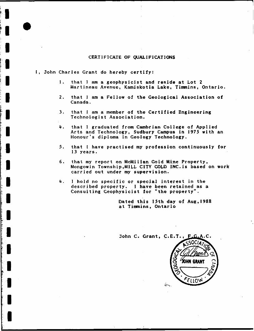
CERTIFICATE OF QUALIFICATIONS
I, John Charles Grant do hereby certify:
1. that I am a geophysicist and reside at Lot 2Martineau Avenue, Kamiskotia Lake, Timmins, Ontario.
2. that I am a Fellow of the Geological Association of Canada.
3. that l am a member of the Certified Engineering Technologist Association.
k. that I graduated from Cambrian College of Applied Arts and Technology, Sudbury Campus in 1975 with an Honour's diploma in Geology Technology.
5. that I have practised my profession continuously for 13 years.
6. that my report on McMillan Gold Mine Property,Mongowin Township,MILL CITY GOLD INC.is based on work carried out under my supervision.
k. I hold no specific or special interest in the described property. I have been retained as a Consulting Geophysicist for "the property".
Dated this 15th day of Aug.1988 at Timmins, Ontario
John C. Grant, C.E.T.. F.C f A.C.

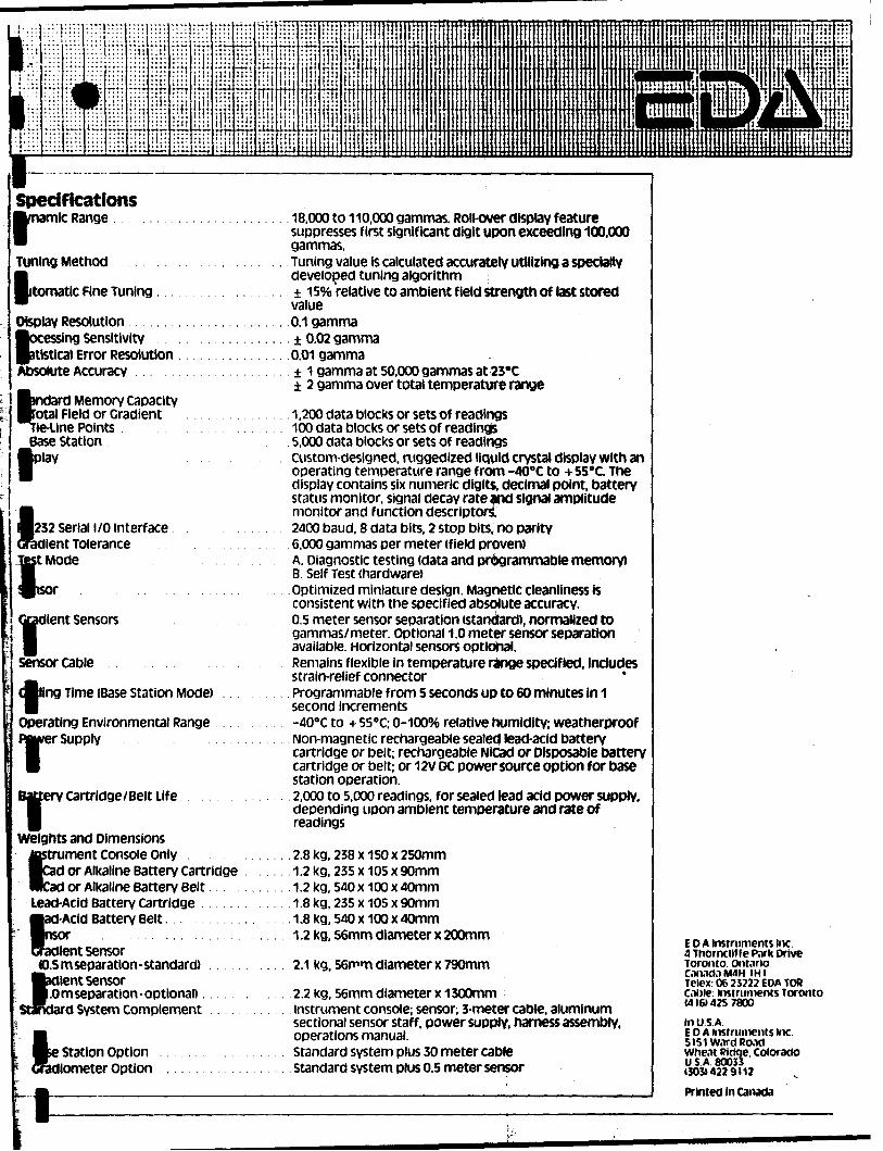
APPENDIX A

ImmffiimltttHm tt ffllHl ut l St !lt(t!tl! lMl!tt'Ei!'H*t'ttIl*lt'ltlltt*HII 1 lItI !ii i liliMliHii! i! lii iii M IIMMII ii li111 ' ' )ittwttmj
Major Benefits of the OMNI PLUS* combined VLF/Magnetometer/cradiometer
System
* NO orientation Required
9 Three VLF Magnetic Parameters Recorded
9 Automatic Calculation of Fraser Filter
9 Calculation of Ellipticity
* Automatic Correction of Primary Field variations
m Measurement of VLF Electric Field
l;:::ttt
H:
"TT
lijiH'i til!l-
ffi!i!.11 l
iilj ' i!
ir
ffi:till 1111
m kH tumuli:
specifications rTiamic Range .
Tuning Method
itomatic Fine Tuning.
Display Resolution . ocessing sensitivity |atistical Error Resolution Absolute Accuracy .
rd Memory capacity Irotal Field or Gradient
Line Points Base station
ay
'32 Serial l/O interface lent Tolerance Mode
lient Sensors
Sensor Cable
Aing Time (Base Station Mode)
Operating Environmental Range ;r supplyMwei
Baft:ery cartridge/Belt Life
Weights and Dimensions tostrument Console only Cad or Alkaline Battery Cartridge Rkad or Alkaline Battery Belt Lead-Acid Battery cartridge
l-Acid Battery Belt.
it sensor JD.5 m separation - standard)
lent Sensor.0 m separation-optional)..
d System Complement
Station Option liometer Option
18,000 to 110,000 gammas. Roll-over display feature suppresses first significant digit upon exceeding 100,000 gammas.Tuning value Is calculated accurately utilizing a specially developed tuning algorithm 150/*) relative to ambient field strength of last storedvalue0.1 gamma± 0.02 gamma0.01 gamma± 1 gamma at 50.000 gammas at 23'C 2 gamma over total temperature range
1,200 data blocks or sets of readings100 data blocks or sets of readings5,000 data blocks or sets of readingsCustom-designed, mggedized liquid crystal display with anoperating temperature range from -400C to -i- 55ec. Thedisplay contains six numeric digits, decimal point, batterystatus monitor, signal decay rate and signal amplitudemonitor and function descriptors.2400 baud, 8 data bits, 2 stop bits, no parity6,000 gammas per meter (field proven)A. Diagnostic testing (data and programmable memory)B. Self Test (hardware)Optimized miniature design. Magnetic cleanliness isconsistent with the specified absolute accuracy.0.5 meter sensor separation (standard), normalized togammas/meter. Optional 1.0 meter sensor separationavailable. Horizontal sensors optional.Remains flexible in temperature range specified, includesstrain-relief connectorProgrammable from 5 seconds up to 60 minutes in 1second Increments-400C to 4- 55"C; D-100% relative humidity; weatherproofNon-magnetic rechargeable sealed lead-acid batterycartridge or belt; rechargeable NiCad or Disposable batterycartridge or belt; or 12V DC power source option for basestation operation.2,000 to 5,000 readings, for sealed lead acid power supply,depending upon ambient temperature and rate ofreadings
.2.8 kg, 238 x 150 x 250mm 1.2kg, 235 x 105 x 90mm 1.2kg, 540 x 100 x 40mm 1.8kg, 235 x 105 x 90mm
.1.8 kg, 540 x 100 x 40mm 1.2 kg, 56mm diameter x 200mm
2.1 kg, 56mm diameter x 790mm
2.2 kg, 56mm diameter x 1300mminstrument console; sensor; 3-meter cable, aluminumsectional sensor staff, power supply, harness assembly,operations manual.Standard system plus 30 meter cableStandard system plus 0.5 meter sensor
EDA instruments inc. 4 Thornclif fe Pnrk Drive Toronto, Ont.irio Con.iti.iM4H IHI Telex: 06 25222 EDA TOR Came: instruments Toronto 1416)425 7800in USA.EDA instruments Inc.5lS1W.irdRo.idWhe.it Ridge. ColoradoUSA 8003313031422 9112
Printed in Canada
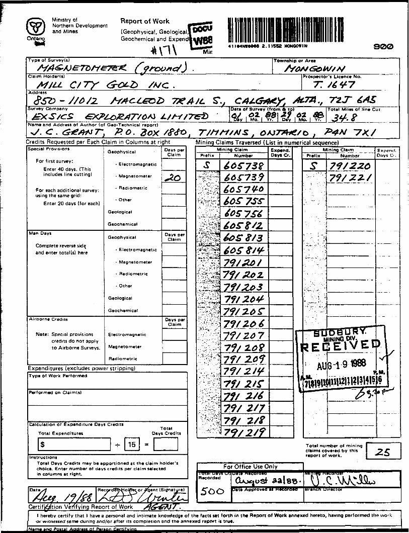
Ministry ofNorthern Developmentand Mines
Ontarintariq
Report of Work
(Geophysical, Geological Geochemical and
*n\ 41I94NWQM8 2.11552 MONGOWIN 9OOType of Survey(s)
Claim Holder(s)
MJLL C/TY t-rOt-Z)Address
Survey Company
Township or Area
/A/C .Prospector's Licence No.
77 /6V-7
'.e&b TKA/t. S*y C4AG*A.y, stott., TZT 6*4SDate of Survey (from 6 to) ^^
rV\AJ J J 't*-/ JTTt-i^ ^5X i^^L, 58 1 ~r 02 oJ3 u'^J *-ff f t s *z*s *55 V | Mo j y^i Da*v Mo j y^
Total Miles of line Cut
3*?Name and Address of Author (of Geo-Technical report)
Credits Requested per Each Claim inSpecial Provisions
For first survey:
Enter 40 days. (This includes line cutting)
For each additional survey: using the same grid:
Enter 20 days (for each)
Man Days
Complete reverse side, and enter total (s) here
Airborne Credits
Note: Special provisions credits do not apply to Airborne Surveys.
Columns at right Mining Claims Traversed (List in numerical sequence)
Geophysical
- Electromagnetic
- Magnetometer
- Radiometric
- Other
Geological
Geochemical
Geophysical
- Electromagnetic
- Magnetometer
- Radiometric
- Other
Geological
Geochemical
Electromagnetic
Magnetometer
Radiometric
Days per Claim
+2O
Days per Claim
Days per Claim
Expenditures (excludes power stripping)
:-
Type of Work Performed
Performed on Claim(s)
Calc ulation of Expenditure Days Credits
Total Expenditures
S * 15
Total Days Credits
-
Instructions Total Days Credits may be apportioned at the claim holder's choice. Enter number of days credits per claim selected in columns at right.
fDat
t
t-/] , R ecorcf8^-lolflflt or Agent (Signature)
Mining ClaimPrefix
S
.V. :.7;-*'-'Vv' * ' ' : * *'-;-g
" ^'^.r^f
Number
60 S 73Z66^73966S7V-66oS TS^40 S 7S660^X^260S 8/3
WiJ3 6os 8 /v-
'^•'s . '-'- *.*'V
.;!:V.'- .-^'.-"',
.'^'".''.'
79/Z6J71/ Zo 2.71/2037 J/ 26*71/ 26 S71 f 26671 / 26 771 / 20?71/ 2617f72/^ 7f/ 2 /S71/ 2/671/ 2/771/ 2/?7?/ 2S?
Expend. Day* Cr.
i
For Office Use Only
Recorded
5oc(Locust aa lee-
-j Data Approved at necoraea
Mining ClaimPrefix
5*
t?EC
5 AU
Total nu claims cc report oi
Number
71/22071/22/
8-1 91988 ^
)111112|li2|3|4|5~" fi*P
Expot^ti. Days Ci .
; -
ww
V
M.6 f^
mber of mining vered by this "7 C work. *-*J
MIIIIIVU nBCOraer ..
(j.CAU:JKLBrancn Director
CertifJ^/tion Verifying Report of Work /J(f^A}7^.hereby certify that 1 have a personal
or witnessed' same during and/or afterand intimate knowledge of the facts set forth in the Report of Work annexed hereto, having performed the wo* k its completion and the annexed report is true.
Ministry olNorthern Developmentand Mines
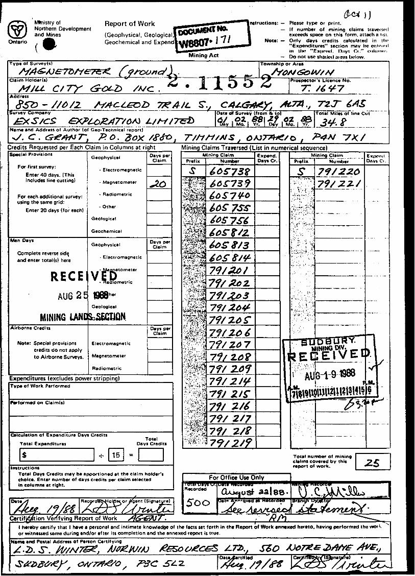
Ontario cReport of Work,(Geophysical, Geologi -Geochemical and Expe|jWQQ07* l l A
l^H*^*^*^*^^
Mining Act
H— Please type or print.— If number of mining claims traversed
exceeds space on this form, attach a list.— Only days credits calculated in the
"Expenditures" section may be entered in the "Expend. Days Cr." columns.
— Do not use shaded areas below.Type of Survey(s)
Claim Holder(s)
CJ7Y * 115ITo
|T^5
Township or Area
1*rospector's Licence No.
T.Address
Survey Company
Name and Address of Author (of Gee-Technical report)
, P.O.Box /Sgo ,
Date *f Survey if rom a to) (Total Mile* of Fine Ciif
Credits Requested per Each Claim in Columns at rightSpecial Provisions
For first survey:Enter 40 days. (This includes line cutting)
For each additional survey: using the same grid:
Enter 20 days (for each)
Man Days
Complete reverse sidp and enter total (s) here
RECE!— —— — —— ——— — Allft OCAirborne Credits MLHJ fi \J
Note: aimnaipsto Airborne Surveys.
Geophysical
- Electromagnetic
- Magnetometer
- Radiometric
- Other
Geological
Geochemical
Geophysical
- Electromagnetic
- Magnetometer
- Radiometric
- Other
VetE^DGeochemical1988 —— ——
wtrnr*Magnetometer
Radiometric
Days per Claim
44920
Days per Claim
Days per Claim
Expenditures (excludes power stripping)Type of Work Performed
Performed on Claim(s)
Calculation of Expenditure Days Credits Total Expenditures
Total Days Credits
InstructionsTotal Day* Credits may be apportioned at the claim holder's choice. Enter number of days credits per claim selected In columns at right.
Certification Verifying Report of Work
Mining Claims Traversed (List in numerical sequence)
For Office Use Only
l hereby certify that l have a personal and intimate knowledge of the facts set forth in tht Report of Work annexed hereto, having performed the work or witnessed same during end/or after its completion and the annexed report is true.
Name and Postal Address of Person Certifying•t*
Oate Certified
Ontario
Ministry ofNorthern Developmentand MinesMinistere du Developpement du Nord et des Mines
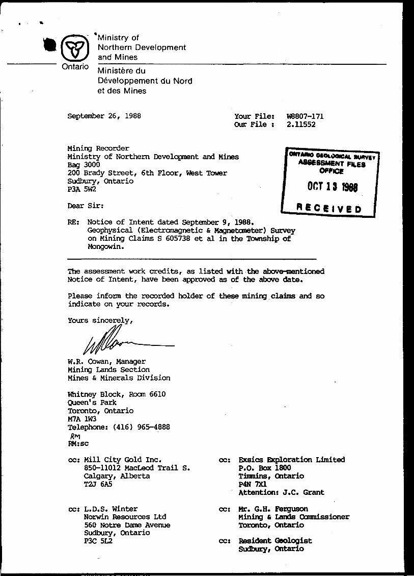
September 26, 1988 Your File: Our File :
W8807-171 2.11552
Mining RecorderMinistry of Northern Development and MinesBag 3000200 Brady Street, 6th Floor, West TowerSudbury, OntarioP3A 5W2
Dear Sir:
ONTMNO OCOMXMC*. BU ASSESSMENT FILE
owce OCT13 1908
j* 6 C 6 l V B DRE: Notice of Intent dated September 9, 1988.
Geophysical (Electromagnetic S. Magnetometer) Survey on Mining Claims S 605738 et al in the Township of Mongowin.
The assessment work credits, as listed with the above-mentioned Notice of Intent, have been approved as of the above date.
Please inform the recorded holder of these mining claims and so indicate on your records.
Yours sincerely,
W.R. Cowan, Manager Mining Lands Section Mines St Minerals Division
Whitney Block, Roan 6610Queen's ParkToronto, OntarioM7A 1W3Telephone: (416) 965-4888R"\ RM:sc
cc: Mill City Gold Inc.850-11012 MacLeod Trail S. Calgary, Alberta T2J 6A5
cc: L.D.S. WinterNorwin Resources Ltd 560 Notre Dame Avenue Sudbury, Ontario P3C 5L2
cc: Exsics Exploration Limited P.O. Box 1800 Tiirodns, Ontario P4N 7X1 Attention: J.C. Grant
cc: Mr. G.H. FergusonMining 6 Lands Commissioner Toronto, Ontario
cc: Resident Geologist Sudbury, Ontario
Ministry ofNorthern Development*"*
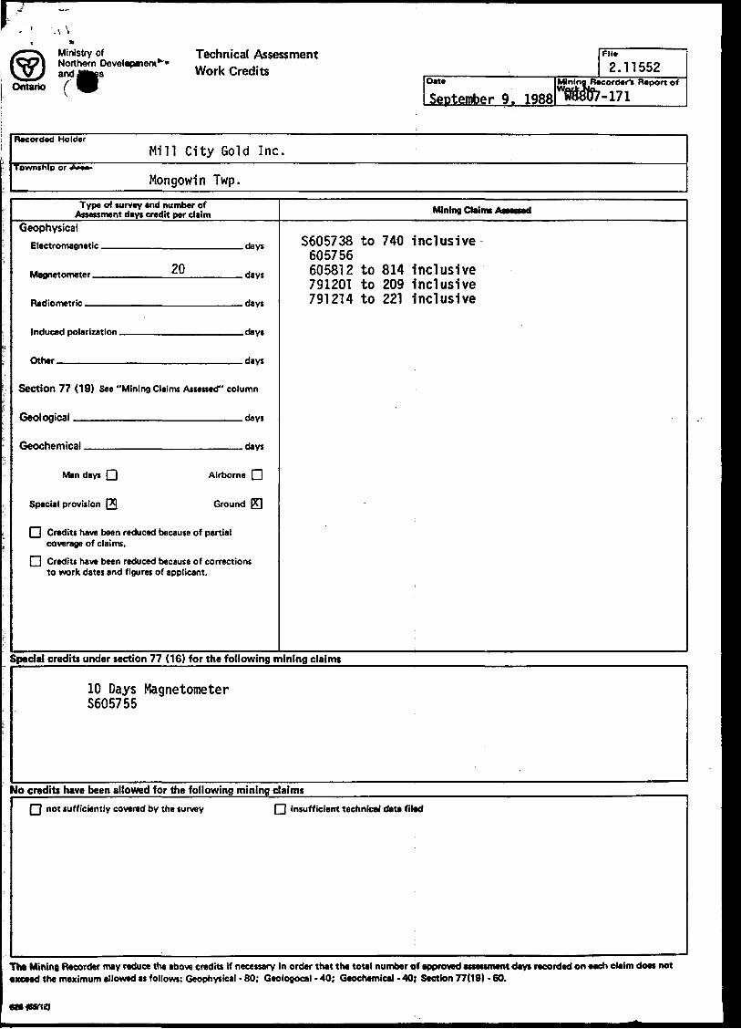
Ontario
Technical Assessment Work Credits
DIM
September 9. 1988
FM*
2.11552Mining Recorder^ Report of
Recorded HolderMill City Gold Inc.
Township or Am
Mongowin Twp.Type of survey and number of
Assessment days credit per claimGeophysical
?0Magnetnmater tu Hays
Parametric Hays
|nHiir*rl polaris'"" . Hays
nthar rtay*
Section 77 (19) See "Mining Claims Assessed" column
Ganlngirjii Hay*
Geochemical , riayc
Man days Q Airborne Q
Special provision (29 Ground PT|
FI Credits have been reduced because of partial coverage of claims.
l~l Credits have been reduced because of corrections to work dates and figures of applicant.
Mining Claims Aitsoed
S605738 to 740 inclusive 605756 605812 to 814 Inclusive 791201 to 209 Inclusive 791214 to 221 Inclusive
Special credits under section 77 (16) for the following mining claims
10 Days Magnetometer S605755
No credits have been allowed for the following mining claimsQ not sufficiently covered by the survey Q insufficient technical data filed
exceed the maximum allowed as follows: Geophysical - 60; Geologocal - 40; Geochemical - 40; Section 77(19) - 60.
Ministry ofNorthern Developmentand Mines
Ontario (*Report of Work(Geophysical, Geological Geochemical and Expend!
Mining Act
nstructions: — Please type or print.—If number of mining claims traversed
exceeds space on this form, attach a list. Note: — Only days credits calculated in iho
"Expenditures" section may he enn-ird in tin? "Ex|MMnl. n.-iyr. Ci." ruhiniir.
— Do not use shaded aieas below.Type of Survey(s)
Claim Holder(s) H |* A JL
Township or Area
Prospector's Licence No.
77Address
7** A/LSurvey Company
&XS/CS
,, 7V.T
Name and Address of Author (of Geo-Technical report)^/. c .
Date of Survey (from 4 tp)
Mo.
Total Miles of line Cut
Credits Requested per Each Claim in Columns at rightSpecial Provisions
For first survey:Enter 40 days. (This includes line cutting)
For each additional survey: using the same grid:
Enter 20 days (for each)
Man Days
Complete reverse side, and enter total (s) here
RECEAU625
MINING UNOAirborne Credits
Note: Special provisions credits do not apply to Airborne Surveys.
Geophysical
- Electromagnetic
- Magnetometer
- Radiometric
- Other
Geological
Geochemical
Geophysical
- Electromagnetic
-J/laflnetometer
VEp- Haoiometric
868*"Geological
SG&ECIJQN
Electromagnetic
Magnetometer
Radiometric
Days per Claim
J.O
Days per Claim
Days per Claim
Expenditures (excludes power stripping)Type of Work Performed
Performed on Claim(s)
Calculation of Expenditure Days Credits
Total Expenditures
S -i- 15
Total Days Credits
s
Instructions Total Days Credits may be apportioned at the claim holder's choice. Enter number of days credits per claim selected in columns at right.
Date
Certification Verifying Report of Work
RecordeTJsHolpeior/igent (Signature)
Xgfrr/
Mining Claims Traversed (List in numerical sequence)Mining Claim
Prefix
Sif
Number
66^739
7SS-t OS 7 St
60S 9/3
79/&0/
7? f ZO S[•V'Vi'V'iif f t l *^w V
gl7f/ ZO 7 20?
\jjl
2/S"
2/7
7J/2/9
Expend. Days Cr. Prefix
Mining ClaimNumber
Expend. D.iys Ci .
73/22.0
MINING.-.- — m^ECIEiVEt)
Total number of mining claims covered by this report of work.
T^xy/h"l hereby certify that l have a personal and intimate knowledge of the facts set forth in tht Report of Work annexed hereto, having performed the wot k or witnessed same during and/or after its completion and the annexed report is true.
Name and Postal Address of Person Certifying
7*3 C . s?/f*
5115000 m
MAP SYM80LOGY MERRITT TWP•7 0 6
Aerial Cabltway
Boundary
Building
Chimney Cliff, Pit, Pile
ContoursBass e^g t . -*~ — "-*
— .Rt**rvoir, Stream. Canal
Control Points
Vtrtltvl
'Culvert Falls
(,~*. ....... —— i -300.0
Tower a *
Transmission Line
Fvnct, Hedge, WallFeature Outline
*4lr le.)
Flooded LandLock tMarsh or Swamp 4* -^ Utility Poles
Wharf .Dock, Pier
Wooded AreaMastMine Head Frame aOulcrop i'"^--"-1
AREAS WITHDRAWN FROM DISPOSITION
M.R.O. - MINING RIGHTS ONLY
S.R.O. - SURFACE RIGHTS ONLY
M.+ S. - MINING AND SURFACE RIGHTS
OrdW No.WHITEFISHAOMINISTFJ^CT \
INDIAN AFFAIRS BRANCH OE-PART-MEN-T—OE-CIT4Z
SAND -AND GRAVEL
787633, /-J78T62
Frooa Lake
LAWSON /' QUARRY
hitefi'sh-' Falls"211
ShawshashtqM
LI .ACE MINECONCESSim
Storehouse Bay
LAKE HURON
•B
LEGENDHIGHWAY AND ROUTE No.OTHER ROADSTRAILS j -SURVEYED LINES: ; l
TOWNSHIPS, BASE LINES, ETC.LOTS, MINING CLAIMS, PARCELS, ETC
UNSURVEYED LINES:LOT LINES -PARCEL BOUNDARY
^ MINING CLAIMS ETC.
RA^lWAY AND RIGHT OF WAY
UTILITY LINES , -
NON-PERENNIAL STREAM
FLOODING OR FLOODING RIGHTS
SUBDIVISION OR COMPOSITE PLAN
RESERVATIONS
ORIGINAL SHORELINE
MARSH OR MUSKEG
MINES
TRAVERSE MONUMENT
DISPOSITION OF CROWN LANDS
TYPE OF DOCUMENT SYMBOL
PATENT. SURFACE St MINING RIGHTS ___._.......... *
.SURFACE RIGHTS ONLY________TO___ O
. MINING RIGHTS ONLY ___..______,.__ O
LEASE. SURFACE ft MINING RIGHTS—_.___-—__ H" .SURFACE RIGHTSONLY____.,-—™...___ H" .MINING RIGHTSONLY—__.______....._- B
LICENCE OF OCCUPATION .___.___—_________ T ORO ER-IN-COUNCIL ™....._,.,,.....—.__—.___ OCRESERVATION ___,,.....'--i.—,;....___——..__ ©CANCELLED ___,,.,,.,___,.............__,^..,., ®SAND S GRAVEL .__.......__........__.__.......... ©
NOTE: MINING RIGHTS IN PARCELS PATENTED PRIOR TO MAV 6. 1913. VESTED IN ORIGINAL PATENTEE BY THE PUBLIC LANDS, ACT. H.S.O. 197O, CHAP. 380. SEC. 83, SUBSEC 1.
500
GRID ZONE '. 17o 1000
M Mr
Chains10 20 30 40 SO M 70
500 OFM*
Ctiaim
1000 2000 3000 4000 SGOO —i i ———i i— F**t
SCALE 1:20 OOO
TOWNSHIP
MONGOWINM.N.R. ADMINISTRATIVE DISTRICT
ESPANOLAMINING DIVISION
SUDBURYLAND TITLES/ REGISTRY DIVISION
SUDBURY
Ministry ofNaturalResources
Land .Management
BranchOntario
OriginalCompaction: NOVEMBER, 1984
Nnmbn
G-2899

28+O
ON
24+O
ON
24+O
ON
-698
M
AR
SH
TL
22+O
ON
556 7
9I2
09
557
I92
20
7917
79I2
I879
I2I5
'"ff
tV20
+OO
N20
+OO
N
I6+O
ON
I6+O
ON
I2+O
ON
I2+O
ON
- 95
8MA
RS
H
8+O
ON
8+O
ON
605720
79I2
05
9I20
66
05
73
©60
5738
4+O
ON
4+O
ON
BL
O+O
OB
L 0+
00
4+O
OS
650 79
I20I
639
79I2
039I
2O4\
\ r©
6224
I0
57
40
8+O
OS
HO
U^B
L
AK
EM
OU
SE
1063
'—LA
KE
64
77
I2+O
OS
I6+O
OS
6O58
I787632
78763I
20+O
OS
l
24+O
OS
28+O
OS
HO
RSE
SHO
LA
KE
LU
OJ in
Ld (f)
(O
LEG
END
Inst
rum
ent:
EDA
OM
NI-P
LUS
Paro
met
res
Mea
sure
d: E
arth
's t
otal
mag
netic
fie
ldAc
cura
cy:
*/-
l na
no-te
slas
Dlur
nals
: C
orre
cted
by
base
sta
tion
reco
rder
Con
tour
Int
erva
l: 0,
100,
200,
300,
400,
500.
......
...Re
fere
nce
Fiel
d: 5
8,oo
o Da
tum
Sub
tract
ed: 5
7,50
0
N
4+OOS
LJ O
CD
8+OOS
12+O
OS
aTL 15+O
OS
16+O
OS
UJ c^ LO
LU
(D in .j
EXSI
CS E
XPLO
RATI
ON L
TD,
P.O.
Box
188
0, P
4N-7
X1Su
ite 1
3, Ho
llinge
r Bl
dg,
Tim
mins
Ont
.Te
leph
one:
705
-267
-415
1
CLIE
NT:
GU
NN
AR l
MIL
L C
ITY
G
OLD
IN
PROP
ERTY
: M
CM
ILLA
N
PR
OP
ER
TYT'
TLE:
C
ON
TO
UR
ED
MA
GN
ET
OM
ET
ER
S
UR
VDa
te:
May
I988
Draw
n: P
.G.
Scal
e:In
ferp
:"
NTS
:
Job
No.
EE-1
03

INST
RUME
NT: O
MNI
-PLU
STR
ANSM
ITTE
R ST
ATIO
N: N
AA,
CUTL
ER M
AINE
FRta
UEN
CY:
24.o
KHZ
PARA
METR
ES M
EASU
RED-
Inp
hase
Dip
Angl
eOP
ERAT
OR:
D. RI
FOU,
u. P
ENTT
INEN
VERT
ICAL
SCA
LE
28+O
ON
24+O
ON
24+O
ON
TL
22+O
ON
7192
2079
I2IB
96
X79
1214
7912
1520
+OO
N20
+OO
N*
*!
^ "^
i C
..
O
t
16+O
ON16
+OO
N
12+O
ON
12+O
ON
8+O
ON
9206
6O57
3860
573© 7
7912
07
4+O
ON
4+O
ON
BL
O+O
OB
L 0+
00
4+O
OS
4+O
OS
4+O
OS
2 ^ 7^12
01B
8224
7912
0479
1203
8+O
OS
8+O
OS
M
l7730
6477
29H
OU
LAK
EI2
+OO
S12
+OO
S
TL
I5+O
OS
I6+O
OS
16+O
OS
7876
3178
7633
87
632
7876
3060
5813
6O5S
I2-3
8 ^
5756
20+O
OS
2O+O
OS
24+O
OS
24+O
OS
28+O
OS
HO
tfSE
SH
O
LAK
E
230


