

EAGLE® XG Diameter SignalingRouter
Policy DRA User Guide910-6820-001 Revision A
July 2013
Copyright 2013 Tekelec. All Rights Reserved. Printed in USA.Legal Information can be accessed from the Main Menu of the optical disc or on the
Tekelec Customer Support web site in the Legal Information folder of the Product Support tab.
Table of Contents
Chapter 1: Introduction.......................................................................7Purpose of this Documentation...............................................................................................8
The Policy DRA Application.......................................................................................8Document Organization...........................................................................................................8Scope and Audience.................................................................................................................9Documentation Admonishments............................................................................................9Related Publications.................................................................................................................9Customer Care Center............................................................................................................10Emergency Response..............................................................................................................13Locate Product Documentation on the Customer Support Site.......................................13
Chapter 2: The Policy DRA Application........................................14Policy DRA Description.........................................................................................................15
The Communication Agent.......................................................................................20The Policy DRA Database..........................................................................................22Subscriber Identification and Binding.....................................................................26Policy DRA Functions................................................................................................27Diameter Routing and Communication with Policy DRA...................................35
Policy DRA Assumptions and Limitations.........................................................................42
Chapter 3: Policy DRA Deployment...............................................43High Level Deployment Description...................................................................................44Deployment Topology............................................................................................................44
Policy DRA in Roaming Scenarios............................................................................46Policy DRA Configurable Components...................................................................47IPFE...............................................................................................................................57
Redundancy.............................................................................................................................59MP Server Redundancy..............................................................................................59Site Redundancy..........................................................................................................60Data Redundancy........................................................................................................60OAM Server Redundancy..........................................................................................62
Policy DRA Scalability............................................................................................................64MP Growth...................................................................................................................65Database Growth.........................................................................................................65
ii910-6820-001 Revision A, July 2013

Mated Pair Growth.....................................................................................................66Small System Support.................................................................................................67
IP Networking.........................................................................................................................68
Chapter 4: Policy DRA Configuration............................................70Policy DRA Configuration Overview..................................................................................71Pre-Configuration Activities..................................................................................................73
Diameter Configuration for Policy DRA.................................................................74Policy DRA Configuration on the NOAM and the SOAM...............................................78
Access Point Names....................................................................................................78Network-Wide Options..............................................................................................82Alarm Settings.............................................................................................................84Congestion Options....................................................................................................88PCRFs............................................................................................................................91Binding Key Priority...................................................................................................94Topology Hiding.........................................................................................................96Site Options..................................................................................................................99Error Codes................................................................................................................102
Post-Configuration Activities..............................................................................................106Enable the Policy DRA Application.......................................................................106Enable Connections...................................................................................................106Status Verification.....................................................................................................107
DSR Bulk Export....................................................................................................................107DSR Bulk Import...................................................................................................................109
Chapter 5: Policy DRA Maintenance............................................115Introduction...........................................................................................................................116Policy DRA Maintenance Pages..........................................................................................116
Policy SBR Status.......................................................................................................116Binding Key Query...................................................................................................117
Alarms, KPIs, and Measurements......................................................................................118Policy DRA and Policy SBR Alarms and Events..................................................119Policy DRA and Policy SBR KPIs............................................................................120Policy DRA and Policy SBR Measurements..........................................................120
Binding and Session Database Auditing...........................................................................121Overload Management.........................................................................................................125
Overload Controls.....................................................................................................125Shutdown...............................................................................................................................128Diameter Maintenance and Status Data for Components, DSR Applications, and
DA-MPs............................................................................................................................129
iii910-6820-001 Revision A, July 2013

Backup and Restore for Policy DRA Configuration Data...............................................130Glossary..................................................................................................................131
iv910-6820-001 Revision A, July 2013
List of FiguresFigure 1: Policy and Charging Control Network with Policy DRA............................................17Figure 2: EAGLE XG DSR Diagram with 3-tiered Topology........................................................19Figure 3: Communication between ComAgents, Policy DRA, and Policy SBR.........................21Figure 4: Subscriber Key Usage.........................................................................................................27Figure 5: Policy DRA PCRF Selection Concepts.............................................................................30Figure 6: Request Processing at the Diameter Routing Function and Policy DRA ..................36Figure 7: Answer Processing at the Diameter Routing Function and Policy DRA...................36Figure 8: Policy DRA Generated Answer Routing.........................................................................37Figure 9: Policy DRA Generated Request Routing........................................................................37Figure 10: Sites, Mated Pairs, and Region.......................................................................................45Figure 11: Policy DRA in Roaming Scenarios.................................................................................46Figure 12: Policy DRA Component Relationships.........................................................................48Figure 13: Example Policy DRA Mated Pair - Hosting Binding Policy SBRs.............................49Figure 14: Example Policy DRA Mated Pair - Not Hosting Binding Policy SBRs.....................50Figure 15: Policy Client, PCRF, and Site Relationships.................................................................51Figure 16: Resource Domains............................................................................................................55Figure 17: Binding Table Partitioning Across Server Groups......................................................61Figure 18: Multi-Table Resources.....................................................................................................61Figure 19: Data Merging - Normal Case..........................................................................................63Figure 20: Data merging - Redundant Site Failure.........................................................................64Figure 21: Smallest Supported Policy DRA Mated Pair................................................................68Figure 22: GUI Structure for 3-tiered DSR Topology with Policy DRA......................................72Figure 23: Policy DRA Default Overload Control Thresholds...................................................126
v910-6820-001 Revision A, July 2013
List of TablesTable 1: Admonishments.....................................................................................................................9Table 2: Example Binding Key Priority Configuration..................................................................25Table 3: Example Key Priority Configuration.................................................................................27Table 4: Topology Hiding Scope Configuration.............................................................................31Table 5: Policy DRA Error Scenarios for Session Integrity...........................................................33Table 6: Session Integrity Conditions and Policy DRA Reaction.................................................34Table 7: Communication between the Diameter Routing Function and the DAI.....................35Table 8: Policy DRA Application Routing Rule Configuration....................................................39Table 9: Answer Processing by Policy DRA....................................................................................39Table 10: Server Group Functions.....................................................................................................52Table 11: Policy SBR Server Group Configuration and Data Redundance................................53Table 12: Policy Client Connection Capability...............................................................................56Table 13: IP Traffic-to-Service Mapping..........................................................................................68Table 14: Access Point Names elements..........................................................................................79Table 15: Network-Wide Options elements....................................................................................82Table 16: Alarm Settings elements....................................................................................................85Table 17: Congestion Options elements...........................................................................................89Table 18: PCRFs page elements.........................................................................................................92Table 19: Binding Key Priority elements.........................................................................................95Table 20: Topology Hiding elements...............................................................................................96Table 21: Site Options elements........................................................................................................99Table 22: Topology Hiding Scope Configuration.........................................................................101Table 23: Policy DRA Error Conditions.........................................................................................102Table 24: Interfaces Supported for Each Error Code....................................................................103Table 25: Error Codes elements.......................................................................................................104Table 26: Valid Import Operations.................................................................................................112Table 27: Policy SBR Status elements.............................................................................................117Table 28: Binding Key Query elements..........................................................................................118Table 29: Effects of Stale Binding and Session Records...............................................................121Table 30: Audit Report Formats......................................................................................................124Table 31: Diameter Routing Function Message Handling Based on Policy DRA
Operational Status.......................................................................................................................126Table 32: Stack Event Load Shedding............................................................................................128Table 33: Policy DRA Operational Status......................................................................................129
vi910-6820-001 Revision A, July 2013

Chapter
1Introduction
This chapter contains a brief description of the PolicyDiameter Relay Agent (Policy DRA) feature. The
Topics:
• Purpose of this Documentation.....8 contents include sections about the document scope,• Document Organization.....8 audience, and organization; how to find related
publications; and how to contact Tekelec forassistance.
• Scope and Audience.....9• Documentation Admonishments.....9• Related Publications.....9• Customer Care Center.....10• Emergency Response.....13• Locate Product Documentation on the Customer
Support Site.....13
7910-6820-001 Revision A, July 2013

Purpose of this Documentation
This documentation:
• Gives a conceptual overview of the application's purpose, architecture, and functionality• Describes the pages and fields on the application GUI (Graphical User Interface)• Provides procedures for using the application interface• Explains the organization of, and how to use, the documentation
The Policy DRA Application
The Policy Diameter Routing Agent (Policy DRA pr P-DRA) is a feature of the Tekelec DiameterSignaling Router (DSR) product, which is part of the Eagle XG product line of Tekelec signalingproducts. P-DRA solves Diameter routing problems that are specific to the policy management domain.
Policy DRA offers a scalable, geo-diverse Diameter application that creates a binding between asubscriber and a Policy and Charging Rules Function (PCRF) and routes all policy messages for agiven subscriber to the PCRF that currently hosts that subscriber’s policy rules. Policy DRA can performTopology Hiding to hide the PCRF from specified Policy Clients.
Policy DRA provides the following capabilities:
• Distribution of Gx, Gxx, and S9 Policy binding capable sessions across available PCRFs• Binding of subscriber keys such as IMSI, MSISDN, and IP addresses to a selected PCRF when the
initial Gx, Gxx, or S9 sessions are already established to that PCRF• Network-wide correlation of subscriber sessions such that all Policy sessions for a given subscriber
are routed to the same PCRF• Use of multiple binding keys that identify a subscriber, so that sessions with these binding keys
can still be routed to the PCRF assigned to the subscriber• Efficient routing of Diameter messages such that any Policy Client in the network can signal to any
PCRF in the network, and vice-versa, without requiring full-mesh Diameter connectivity• Hiding of PCRF topology information from specified Policy Clients
The Policy DRA GUI pages allow performing configuration and maintenance tasks, editing SystemOptions, and viewing elements for the Policy DRA Configuration and Maintenance components.
The Policy Session Binding Repository (Policy SBR) hosts the Policy Session and Policy Bindingdatabases, which provide a distributed scalable and High Available (HA) database function to thePolicy DRA application for storing and managing the Policy Session data and the subscriber-PCRFBinding data.
Document Organization
This document is organized into the following chapters:
• Introduction contains general information about the DSR documentation, the organization of thisdocument, and how to get technical assistance.
8910-6820-001 Revision A, July 2013
Introduction
• The Policy DRA Application describes the topology, architecture, components, and functions of thePolicy DRA application and the Policy Session Binding Repository (Policy SBR).
• Policy DRA Deployment describes Policy DRA and Policy SBR deployment in a DSR system.• Policy DRA Configuration describes configuration of Policy DRA application components.• Policy DRA Maintenance describes Policy DRA Maintenance functions, and Diameter Maintenance
functions that provide maintenance and status information for Policy DRA and the Policy SBR.
Scope and Audience
This document is intended for anyone responsible for configuring and using the EAGLE XG DSRPolicy DRA application and Policy Session Binding Repository. Users of this manual must have aworking knowledge of telecommunications and network installations.
Documentation Admonishments
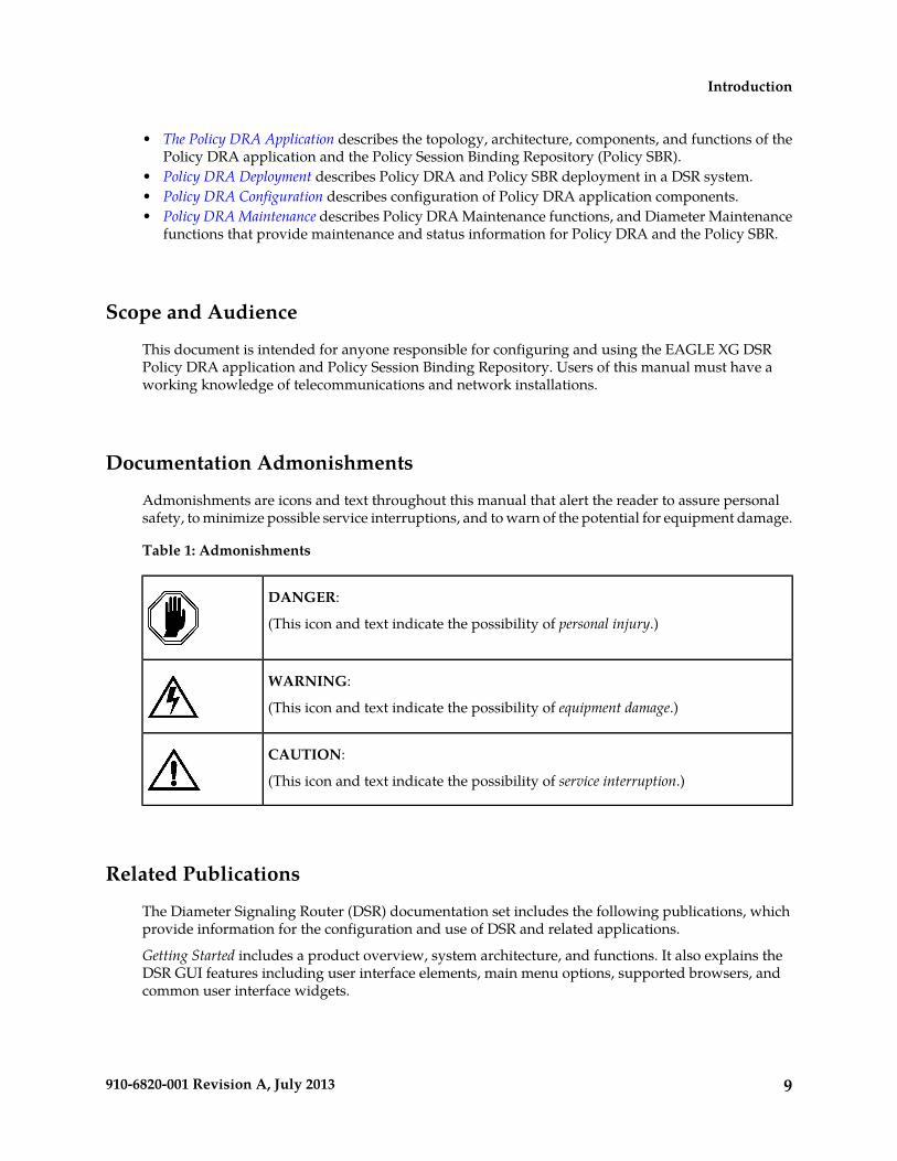
Admonishments are icons and text throughout this manual that alert the reader to assure personalsafety, to minimize possible service interruptions, and to warn of the potential for equipment damage.
Table 1: Admonishments
DANGER:
(This icon and text indicate the possibility of personal injury.)
WARNING:
(This icon and text indicate the possibility of equipment damage.)
CAUTION:
(This icon and text indicate the possibility of service interruption.)
Related Publications
The Diameter Signaling Router (DSR) documentation set includes the following publications, whichprovide information for the configuration and use of DSR and related applications.
Getting Started includes a product overview, system architecture, and functions. It also explains theDSR GUI features including user interface elements, main menu options, supported browsers, andcommon user interface widgets.
9910-6820-001 Revision A, July 2013
Introduction
Feature Notice describes new features in the current release, provides the hardware baseline for thisrelease, and explains how to find customer documentation on the Customer Support Site.
Roadmap to Hardware Documentation provides links to access manufacturer online documentation forhardware related to the DSR.
Operation, Administration, and Maintenance (OAM) Guide provides information on system-levelconfiguration and administration tasks for the advanced functions of the DSR, both for initial setupand maintenance.
Communication Agent User Guide explains how to use the Communication Agent GUI pages to configureRemote Servers, Connection Groups, and Routed Servers, and to maintain configured connections.
Diameter and Mediation User Guide explains how to use the Diameter GUI pages to manage theconfiguration and maintenance of Local and Peer Nodes, connections, Configuration Sets, Peer RoutingRules, Application Routing Rules, and System, DNS, and Local Congestion options; and explains howto configure and use Diameter Mediation.
IP Front End (IPFE) User Guide explains how to the use the IPFE GUI pages to configure IPFE todistribute IPv4 and IPv6 connections from multiple clients to multiple nodes.
Range-Based Address Resolution (RBAR) User Guide explains how to use the RBAR GUI pages to configureRBAR to route Diameter end-to-end transactions based on Diameter Application ID, Command Code,Routing Entity Type, and Routing Entity address ranges and individual addresses.
Full-Address Based Resolution (FABR) User Guide explains how to use the FABR GUI pages to configureFABR to resolve designated Diameter server addresses based on Diameter Application ID, CommandCode, Routing Entity Type, and Routing Entity addresses.
Charging Proxy Application (CPA) and Offline Charging Solution User Guide describes the Offline ChargingSolution and explains how to use the CPA GUI pages to set System Options for CPA, configure theCPA's Message Copy capability, and configure the Session Binding Repository for CPA.
Policy DRA User Guide describes the topology and functions of the Policy Diameter Routing Agent(Policy DRA) DSR application and the Policy Session Binding Repository, and explains how to usethe GUI pages to configure Policy DRA.
DSR Alarms, KPIs, and Measurements Reference Guide provides detailed descriptions of alarms, events,Key Performance Indicators (KPIs), and measurements; indicates actions to take to resolve an alarm,event, or unusual Diameter measurement value; and explains how to generate reports containingcurrent alarm, event, KPI, and measurement information.
DSR Administration Guide describes DSR architecture, functions, configuration, and tools and utilities(IPsec, Import/Export, DIH, and database backups); and provides references to other publications formore detailed information.
Customer Care Center
The Tekelec Customer Care Center is your initial point of contact for all product support needs. Arepresentative takes your call or email, creates a Customer Service Request (CSR) and directs yourrequests to the Tekelec Technical Assistance Center (TAC). Each CSR includes an individual trackingnumber. Together with TAC Engineers, the representative will help you resolve your request.
The Customer Care Center is available 24 hours a day, 7 days a week, 365 days a year, and is linkedto TAC Engineers around the globe.
10910-6820-001 Revision A, July 2013
Introduction
Tekelec TAC Engineers are available to provide solutions to your technical questions and issues 7days a week, 24 hours a day. After a CSR is issued, the TAC Engineer determines the classification ofthe trouble. If a critical problem exists, emergency procedures are initiated. If the problem is not critical,normal support procedures apply. A primary Technical Engineer is assigned to work on the CSR andprovide a solution to the problem. The CSR is closed when the problem is resolved.
Tekelec Technical Assistance Centers are located around the globe in the following locations:
Tekelec - Global
Email (All Regions): [email protected]
• USA and Canada
Phone:
1-888-FOR-TKLC or 1-888-367-8552 (toll-free, within continental USA and Canada)
1-919-460-2150 (outside continental USA and Canada)
TAC Regional Support Office Hours:
8:00 a.m. through 5:00 p.m. (GMT minus 5 hours), Monday through Friday, excluding holidays• Caribbean and Latin America (CALA)
Phone:
+1-919-460-2150
TAC Regional Support Office Hours (except Brazil):
10:00 a.m. through 7:00 p.m. (GMT minus 6 hours), Monday through Friday, excluding holidays
• Argentina
Phone:
0-800-555-5246 (toll-free)• Brazil
Phone:
0-800-891-4341 (toll-free)
TAC Regional Support Office Hours:
8:00 a.m. through 5:48 p.m. (GMT minus 3 hours), Monday through Friday, excluding holidays• Chile
Phone:
1230-020-555-5468• Colombia
Phone:
01-800-912-0537• Dominican Republic
Phone:
1-888-367-8552
11910-6820-001 Revision A, July 2013
Introduction

• Mexico
Phone:
001-888-367-8552• Peru
Phone:
0800-53-087• Puerto Rico
Phone:
1-888-367-8552 (1-888-FOR-TKLC)• Venezuela
Phone:
0800-176-6497
• Europe, Middle East, and Africa
Regional Office Hours:
8:30 a.m. through 5:00 p.m. (GMT), Monday through Friday, excluding holidays
• Signaling
Phone:
+44 1784 467 804 (within UK)• Software Solutions
Phone:
+33 3 89 33 54 00
• Asia
• India
Phone:
+91-124-465-5098 or +1-919-460-2150
TAC Regional Support Office Hours:
10:00 a.m. through 7:00 p.m. (GMT plus 5 1/2 hours), Monday through Saturday, excludingholidays
• Singapore
Phone:
+65 6796 2288
TAC Regional Support Office Hours:
9:00 a.m. through 6:00 p.m. (GMT plus 8 hours), Monday through Friday, excluding holidays
12910-6820-001 Revision A, July 2013
Introduction
Emergency Response
In the event of a critical service situation, emergency response is offered by the Tekelec Customer CareCenter 24 hours a day, 7 days a week. The emergency response provides immediate coverage, automaticescalation, and other features to ensure that the critical situation is resolved as rapidly as possible.
A critical situation is defined as a problem with the installed equipment that severely affects service,traffic, or maintenance capabilities, and requires immediate corrective action. Critical situations affectservice and/or system operation resulting in one or several of these situations:
• A total system failure that results in loss of all transaction processing capability• Significant reduction in system capacity or traffic handling capability• Loss of the system’s ability to perform automatic system reconfiguration• Inability to restart a processor or the system• Corruption of system databases that requires service affecting corrective actions• Loss of access for maintenance or recovery operations• Loss of the system ability to provide any required critical or major trouble notification
Any other problem severely affecting service, capacity/traffic, billing, and maintenance capabilitiesmay be defined as critical by prior discussion and agreement with the Tekelec Customer Care Center.
Locate Product Documentation on the Customer Support Site
Access to Tekelec's Customer Support site is restricted to current Tekelec customers only. This sectiondescribes how to log into the Tekelec Customer Support site and locate a document. Viewing thedocument requires Adobe Acrobat Reader, which can be downloaded at www.adobe.com.
1. Log into the Tekelec Customer Support site.
Note: If you have not registered for this new site, click the Register Here link. Have your customernumber available. The response time for registration requests is 24 to 48 hours.
2. Click the Product Support tab.3. Use the Search field to locate a document by its part number, release number, document name, or
document type. The Search field accepts both full and partial entries.4. Click a subject folder to browse through a list of related files.5. To download a file to your location, right-click the file name and select Save Target As.
13910-6820-001 Revision A, July 2013
Introduction

Chapter
2The Policy DRA Application
The Policy Diameter Routing Agent, or Policy DRA,is a feature of the Tekelec Diameter Signaling Router
Topics:
• Policy DRA Description.....15 (DSR) product, which is part of the Eagle XG• Policy DRA Assumptions and Limitations.....42 product line of Tekelec signaling products. Policy
DRA runs as a DSR Application, to solve Diameterrouting problems that are specific to the PolicyManagement domain.
Policy Session Binding Repository servers host thePolicy Session and Policy Binding databases for useby the Policy DRA application.
14910-6820-001 Revision A, July 2013
Policy DRA Description
With the advent of LTE and high-speed wireless networks, operators and service providers need toefficiently manage subscriber resource usage across their entire network. To accomplish network-wideresource monitoring and control requires identification of subscriber resource usage using multiplekeys (such as IMSI, MSISDN, and IP addresses) in a network with large numbers of Policy EnforcementClients and Policy rules servers (PCRFs). Subscriber requests for access to network resources must berouted to a single PCRF in the network so that Policy decisions can be made with knowledge of allthe resources being used by all of that subscriber’s Policy sessions.
The Policy Diameter Relay Agent, or Policy DRA, is a feature of the Tekelec Diameter Signaling Router(DSR) product, which is part of the Eagle XG product line of Tekelec signaling products. Policy DRAruns as a DSR Application that interfaces with the Diameter Routing Function, to solve Diameterrouting problems that are specific to the Policy and Charging Control (PCC) management domain asdefined in 3GPP specifications.
In Policy DRA, subscribers are dynamically assigned to a PCRF when the initial bearer session (Gx orGxx interface) is created. All subscriber Policy sessions from anywhere in the network are routed tothe assigned PCRF until that subscriber’s last Gx or Gxx session ends, at which point the next Gx orGxx session may be routed to a different PCRF. This dynamic mapping of subscribers to PCRFsprovides automatic load distribution to available PCRFs, while still mapping all of a subscriber’ssessions to a single PCRF.
In addition to managing a subscriber’s resource usage across the network, network providers mayhave a need to perform Topology Hiding of the PCRF from some Policy Clients. Topology Hidingprevents the Policy Client from obtaining knowledge of the PCRF identity (host name or IP address),or knowledge of the number or location of PCRFs deployed in the network.
Policy DRA System Architecture
A Policy DRA DSR consists of the following architectural components:
• Policy Diameter Relay Agent (Policy DRA) application
The Policy DRA application is a DSR application and makes use of the functions of the DiameterDSR Application Infrastructure (DAI), Diameter Routing Function, and Diameter Transport Function.The DAI and Diameter functions enable the Policy DRA application to:
• Receive Diameter messages (Requests and Answers) from Diameter Peers for processing• Route Diameter messages (Requests and Answers) to Diameter Peers• Communicate Operational Status and other maintenance information to and from the Diameter
Routing Function• Make use of the standard congestion handling procedures• Make use of the standard alarms, events, KPIs, and measurements functions
Note: The Range Based Address Resolution (RBAR) DSR Application and the Policy DRAapplication can run together in the same DA-MP.
Configured Application Routing Rules are used by the Diameter Routing Function to determinewhether a received Diameter message will be routed to the Policy DRA application or routed to aDiameter Peer in the network. The Application Routing Rules are a prioritized list ofuser-configurable routing rules based upon the Diameter message Application ID, Command-Code,Destination-Realm/Host, and Origin-Realm/Host.
15910-6820-001 Revision A, July 2013
The Policy DRA Application
Peer Route Tables (PRT) are used to instruct the Diameter Routing Function on how the egressDiameter messages will be routed to the network. Each PRT is configured with a prioritized list ofPeer Routing Rules that define routing to Peers based upon the content of the Diameter messagesto be routed.
• Policy Session Binding Repository (Policy SBR)
The Policy SBR provides a distributed scalable and High Available (HA) database function to thePolicy DRA application for storing and managing the policy Session data and the subscriber-PCRFBinding data. A Session in the context of the Policy DRA application refers to a Diameter sessionover a policy interface (Gx/Gxx, Rx, S9) that the Policy DRA processes. A Binding refers to anassociation between a subscriber and a PCRF that is assigned to provide policy rules to thatsubscriber.
The Policy SBR runs on different servers than those running the Diameter Agent Message Processor(DA-MP) and Policy DRA application. The Policy SBR servers communicate with Policy DRA usingthe services of the Communication Agent (ComAgent). Policy SBR servers also communicate withother Policy SBR servers for auditing to maintain database consistency.
The Policy SBR servers contain the databases to store the session and binding data, and will respondto requests from P-DRA to add, delete, and update those database records. The Policy SBR isdescribed in more detail in The Policy DRA Database.
A Policy SBR can host a Session database, a Binding database, or both, depending on the PolicyDRA deployment.
• Policy DRA and Policy SBR interface through the Communication Agent (ComAgent)
The Policy DRA application uses the Communication Agent (ComAgent) for communication withthe Policy Session Binding Repository (Policy SBR) for managing session and binding databaseoperations. The ComAgent provides an interface and means to enable the Policy DRA MPs andthe Policy SBR MPs to communicate with each other through reliable ComAgent routing services.The ComAgent Direct Routing service and HA service are directly employed by the Policy DRAand Policy SBR servers.
The Policy SBR communicates with a Policy DRA server (as its local Policy DRA server) and otherPolicy SBR servers in the Policy DRA network through the ComAgent, to create, update, removeand audit the Binding and Session database records.
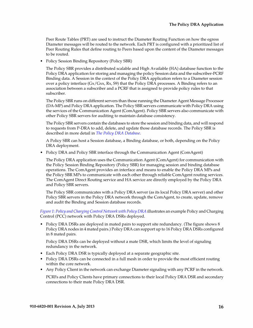
Figure 1: Policy and Charging Control Network with Policy DRA illustrates an example Policy and ChargingControl (PCC) network with Policy DRA DSRs deployed.
• Policy DRA DSRs are deployed in mated pairs to support site redundancy. (The figure shows 8Policy DRA nodes in 4 mated pairs.) Policy DRA can support up to 16 Policy DRA DSRs configuredin 8 mated pairs.
Policy DRA DSRs can be deployed without a mate DSR, which limits the level of signalingredundancy in the network.
• Each Policy DRA DSR is typically deployed at a separate geographic site.• Policy DRA DSRs can be connected in a full mesh in order to provide the most efficient routing
within the core network.• Any Policy Client in the network can exchange Diameter signaling with any PCRF in the network.
PCRFs and Policy Clients have primary connections to their local Policy DRA DSR and secondaryconnections to their mate Policy DRA DSR.
16910-6820-001 Revision A, July 2013
The Policy DRA Application
• A Policy Client can reach any PCRF in the network with a maximum of 3 Diameter hops with atmost one WAN traversal between Policy DRA DSRs.
If all 3 hops are used, they are: Policy Client to Policy DRA DSR, Policy DRA DSR to another PolicyDRA DSR, and Policy DRA DSR to PCRF.
Figure 1: Policy and Charging Control Network with Policy DRA
High Level Policy DRA Description
A Policy DRA DSR consists of a number of Policy DRA DA-MPs , a number of Policy SBR servers,OAM servers, and (optionally) IP Front End (IPFE)servers.
The DSR product supports a 3-tiered DSR Topology, which is required for Policy DRA. (2-tiered DSRTopology is not supported for Policy DRA). The OAM functions are described in 3-Tiered DSR Topology.
The Policy DRA DA-MPs are responsible for handling Diameter signaling and the Policy DRA functions.See Policy DRA Functions.
Policy SBR servers host the Policy Session and Policy Binding databases. These are special purposeMP blades that provide an off-board database for use by the Policy DRA application hosted on thePolicy DRA DA-MPs. See The Policy DRA Database.
17910-6820-001 Revision A, July 2013
The Policy DRA Application

Each Policy DRA DSR hosts connections from Policy Clients and PCRFs. Policy Clients are devices(not provided by Tekelec) that request authorization for access to network resources on behalf of userequipment (such as mobile phones) from the PCRF. Policy Clients sit in the media stream and enforcePolicy rules specified by the PCRF. Policy authorization requests and rules are carried in Diametermessages that are routed through Policy DRA. Policy DRA makes sure that all Policy authorizationrequests for a given subscriber are routed to the same PCRF.
Policy DRA DSRs can be deployed in mated pairs such that Policy session state is not lost even if anentire Policy DRA DSR fails or becomes inaccessible. When Policy DRA mated pairs are deployed,Policy Clients and PCRFs are typically cross-connected such that both Policy DRA DSRs haveconnections to all Policy Clients and all PCRFs at both mated sites.
The Policy DRA can be deployed for various network scenarios as a Policy routing agent, includingthe roaming scenarios. Policy DRAs can be located in Home Access and Visited Access networks. Inaddition to communicating to the Policy Clients and Policy servers using Gx/Gxx and Rx interfacesin their own network, the Policy DRAs can communicate to each other across the Visited and Homenetworks using the S9 interface for session binding. See deployment details in Deployment Topology.
Policy DRA Network is the term used to describe one or more sets of Policy DRA mated pairs that allshare a common Binding database and NOAM server pair. All Policy Clients and PCRFs are reachablefor Diameter signaling from any Policy DRA DSR in the Policy DRA network.
IP Front End (IPFE) provides traffic load balancing across connections in the system. IPFE is notmandatory, but is typically deployed with Policy DRA. Use of IPFE with Policy DRA is described inIPFE.
Policy DRA Major Functions
Policy DRA functions are described in Policy DRA Functions. The Policy DRA application providesthe following major capabilities:
• Distribution of Gx, Gxx, and S9 Policy binding capable sessions across available PCRFs• Binding of subscriber keys such as IMSI, MSISDN, and IP addresses to a selected PCRF when the
initial Gx, Gxx, or S9 sessions are already established to that PCRF• Network-wide session binding and correlation for all policy sessions related to a subscriber such
that all policy sessions for a given subscriber are routed to the PCRF that is serving the subscriber.• Hiding of PCRF topology information from specified Policy Clients
Policy DRA Configuration
Policy DRA configuration is described in Policy DRA Configuration. Making the Policy DRA applicationfully operational includes:
• DSR System Topology configuration, including hardware, firmware, and network elements, asdescribed in 909-2228-001, DSR 4.X HP C-Class Installation
• Feature Activation for Policy DRA, and for IP Front End (IPFE) if used• OAM configuration of MP Blade Servers and Server Groups, and Signaling Network components,
Policy DRA Mated Pairs and Binding Regions, Resource Domains, Places, and Place Associations• IPFE configuration if used• Configuration of Diameter protocol components to support Policy DRA, including MP Profile
Assignments, Peer Nodes, Route Groups, Route Lists, Peer Routing Rules, and Application RoutingRules
• Configuration of Policy DRA components on the NOAM and the SOAM, with elements for thePolicy SBR database
18910-6820-001 Revision A, July 2013
The Policy DRA Application
• Post-configuration activities, including enabling the Policy DRA application and any configuredDiameter Connections
3-Tiered DSR Topology
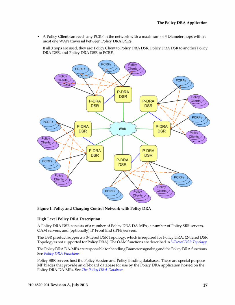
In 3-tiered DSR topology, the OAM server function is split into Network OAM (NOAM) servers andSystem OAM (SOAM) servers. A DSR NOAM Network Element with a pair of NOAM servers isconnected to multiple DSR Signaling Network Elements in the network. Each NOAM Network Elementis connected to up to 16 DSR Signaling Network Elements (configured as up to 8 mated pairs of SOAMsthat interact directly with their respective DA-MPs).
Figure 2: EAGLE XG DSR Diagram with 3-tiered Topology
The 3-tiered DSR topology does not alter existing DSR functions other than separating what can beconfigured or managed at what level (DSR NOAM or DSR SOAM).
The 3-tiered DSR topology architecture includes the following characteristics:
• Each DSR services signaling traffic to and from a collection of Diameter Clients, servers, and agents.• Each DSR supports :
• NOAM and SOAM servers in 3-tiered DSR topology, operating in active/standby mode.• At least two message processors (DA-MPs), operating in active/standby mode, or up to 16
DA-MPs in active/active mode.
• The DSR MPs provide the Diameter message handling function. The DSR MP supports connectionsto all of the DSR Peers.
• DSRs are deployed in mated pairs for purposes of geo-redundancy.
OAM Servers
The DSR Operations, Administration, and Maintenance (OAM) subsystem includes OAM servers(NOAMs and SOAMs for 3-tiered topology) and Message Processors (MPs). Each of these must beconfigured separately. (There is no provisioning data on OAM servers for DSR; the provisioning dataused by the Full Address Based Resolution DSR Application is on the Subscriber Database Server,which has its own OAM servers.)
The 3-tiered DSR topology introduces the DSR SOAM server. The role of the DSR NOAM server takeson network scope instead of Network Element scope. The role of the DSR SOAM is managing a singleDSR system (or DSR Signaling NE).
19910-6820-001 Revision A, July 2013
The Policy DRA Application

In 3-tiered DSR topology, as shown in Figure 2: EAGLE XG DSR Diagram with 3-tiered Topology, thereare NOAM servers, SOAM servers, and MP servers.
A pair of OAM servers make up one OAM component of the DSR. This pair of servers has anactive/standby relationship. The Active server in the pair controls the virtual IP addresses (VIP) thatdirect XMI and IMI traffic to the Active server.
In 3-tiered DSR topology, GUI screens can be used to configure and manage:
• On a DSR NOAM, network topology data such as user accounts, network elements, servers, andserver groups. Policy DRA maintenance functions and some configuration functions are availableon the NOAM.
• On a DSR SOAM, Diameter signaling data (such as Local Nodes, Peer Nodes, Connections, RouteGroups, and Route Lists) and DSR Application data (for Policy DRA, RBAR, and other DSRapplications)
The DA-MP servers process the database updates from NOAM servers and SOAM servers and performthe real-time signaling. The DA-MP servers also supply the Platform MEAL data, Diameter signalingMEAL data, and DSR Application MEAL data to SOAM servers. The SOAM servers retain the Diametersignaling MEAL data and DSR Application MEAL data, and merge the Platform MEAL data to theNOAM servers.
The role of the OAM server is to provide a central operational interface and all OAM functions (forexample, user administration, provisioning and configuration data, database administration, faultmanagement and upgrade functions) for the DSR under its control. The OAM server replicatesconfiguration and provisioning data to and collects all measurements, events, alarms, and log datafrom all Message Processors within the DSR.
The OAM servers provide the following services:
• A central operational interface• Distribution of provisioned data to all MPs of the NE• Event collection and administration from all MPs• User and access administration• Support for a northbound SNMP interface toward an external EMS/NMS; up to 5 SNMP destinations
can be configured• A web-based GUI for configuration tasks
The Communication Agent
The Communication Agent (ComAgent) enables reliable communication between Policy DRA andPolicy SBRs and among Policy SBRs in a scalable and high available Policy DRA network. Figure 3:Communication between ComAgents, Policy DRA, and Policy SBR depicts the communication pathsbetween the Policy DRA, the Policy SBR, and their ComAgents, and the communication paths betweenthe ComAgents.
20910-6820-001 Revision A, July 2013
The Policy DRA Application

Figure 3: Communication between ComAgents, Policy DRA, and Policy SBR
The ComAgent Direct Routing service, HA service, and the MP Overload Management Frameworkare used by the Policy DRA and Policy SBR for communication and for Policy SBR congestion control.(See Policy SBR Congestion for information about the MP Overload Management Framework.)
ComAgent Direct Transfer Service
Through the ComAgent Direct Transfer Service, a DSR application can communicate directly to anotherDSR application. A sending application sets the destination to the IP-Address of the receivingapplication in a message and forwards the message to the ComAgent. The ComAgent locates aconnection to a Peer ComAgent with the same IP-Address and sends the message to the Peer ComAgent,if the connection is In Service. The Peer ComAgent forwards the message to the receiving application.
The Policy DRA application and Policy SBR use the ComAgent Direct Transfer service when a PolicySBR sends Requests and responses to the Policy DRA.
ComAgent HA Service
The DSR High-Availability (HA) Framework provides the capability to allow an application to assignits various functions with identities that are called Resources. A function or Resource can be dividedinto pieces, each of which is called a Subresource. An application configures the HA Framework tomanage its Resources and Subresources.
The HA Framework assigns states (Active, Standby, Spare, Observer, or Out-Of-Service) to eachSubresource based upon the configuration and the health scores of participating DSR MPs.
21910-6820-001 Revision A, July 2013
The Policy DRA Application
• If a Resource or Subresource is Active on a given DSR MP, then the application on that MP isactively providing the function associated with the Resource or Sub-Resource.
• If a Resource or Subresource is Standby, Spare, Observer, or Out-of-Service, then the applicationon the MP is not actively providing the function. The application is waiting to be changed to Activeif the current Active Resource or Subresource be changed from Active due to failures that reducethe other server’s health score.
The Policy DRA application makes use of the Policy SBR database function by sending messagesthrough the ComAgent to the Policy SBR that hosts the active slice of a Session or Binding Subresource.The Policy SBR does the same to other Policy SBRs in a similar manner.
The ComAgent HA Service, combined with the HA Framework, provides the Policy DRA applicationa means to track the placement of the Active Resources and Subresources and route messages reliablyto the Active Policy SBR that may move from one Policy SBR MP to another while transactions areunderway.
The ComAgent HA Service is used by Policy DRA to send messages to Active Policy SBRs for a givenResource and Subresource, and by Policy SBR to send messages to other Active Policy SBRs for a givenResource and Subresource.
When messages arrive from Policy DRA with Resource and Subresource ID, the ComAgent finds theActive Policy SBR MP for the Subresource specified in the message and uses the Resource ID andSubresource ID to route the message to the destination accordingly.
The Policy DRA Database
The Policy DRA application uses the Session and Binding databases in the Policy Session BindingRepository. Subscribers are dynamically assigned to a PCRF; this assignment is called a binding. Thebinding exists as long as the subscriber has at least one Policy Diameter session.
The following points describe a high-level view of Policy DRA Binding and Session databases:
• There is one instance of the Binding database in the entire Policy DRA network.• There is one instance of the Session database per Policy DRA Mated Pair.• Each binding record is associated with at least one Diameter session record. Binding records contain
one Session Reference for each Diameter session that is associated with that binding.• When a binding exists, there will be at least one IMSI Anchor Key, Session, and Session Reference
record.• The IPv4, MISISDN, and IPv6 Alternate Keys are optional. They represent alternate ways, other
than the IMSI, to identify a subscriber.
While technically both are part of the Policy DRA database, the Binding database and the Sessiondatabase are referred to separately because they serve different purposes and have different scopeswithin the Policy DRA network.
Bindings
In the most generic sense, a Binding is a mapping between a subscriber and a PCRF assigned to handlePolicy decisions for that subscriber. In 3GPP networks, however, there is more than one way to identifya subscriber.
Policy DRA supports four subscriber identifiers: IMSI, MSISDN, IPv4 IP Address, and IPv6 IP Address.Of these, IMSI and MSISDN are relatively permanent in that they do not change from call to call. IPaddresses, on the other hand, are assigned by PCEFs to a subscriber’s device for temporary use inaccessing the Internet or other IP services.
22910-6820-001 Revision A, July 2013
The Policy DRA Application
Regardless of the type of subscriber identifier, the relationship of a subscriber to a PCRF assigned bythe Policy DRA must be accessible from anywhere in the Policy DRA network. This means that theinformation in the Binding database must be accessible from all Policy DRA DSR sites. For example,a given IMSI, when bound, will appear in exactly one record in the Binding database, but will beaccessible from any Policy DRA DSR in the Policy DRA network.
Sessions
A Session in this context represents a Diameter session for a Policy interface (Gx, Gxx, S9, or Rx). ThePolicy DRA application maintains session state, for the following reasons:
• Subscriber identifiers used for bindings are created and destroyed as a result of Diameter Requestssent in the context of a Diameter session. In other words, subscriber identifiers are created bybinding capable session-initiating messages and removed by session-terminating messages.
• The binding of a subscriber to a PCRF must remain intact as long as the subscriber has at least oneactive binding capable Diameter session.
• If Topology Hiding is Enabled for a binding dependent session, the bound PCRF is stored in thesession state because binding keys are not guaranteed to exist in all Requests within a Diametersession.
There are two broad categories of Policy sessions:
• Binding capable sessions
A binding capable session is a Policy session that is allowed to cause a new binding to be createdfor a subscriber.
Binding capable sessions are created by Gx, Gxx, or the S9 versions of Gx and Gxx Yes, the tarsCCR-I messages. If a CCR-I message arrives for a Binding Capable Interface, Policy DRA checksfor an existing binding for the IMSI in the message.
• If a binding exists, the CCR-I is routed to the bound PCRF.• If no binding exists, a PCRF is selected and a binding is created for the subscriber IMSI.
If additional subscriber identifiers, or Alternate Keys, are present in the CCR-I, Binding recordsare created for each Alternate Key present in the CCR-I. For example, a binding capable CCR-Imay include a MSISDN and IPv4 and IPv6 addresses in addition to the IMSI. These Alternate Keysexist as long as the session exists.
• Binding dependent sessions
A binding dependent session is a Policy session that cannot cause a binding to be created, andcannot be created unless a binding exists.
Binding dependent sessions are created by Rx or the S9 version of Rx AAR messages. If an AARmessage arrives for a Binding Dependent Interface, Policy DRA checks for an existingbinding using a key in the AAR message.
• If a binding is found, the AAR is routed to the bound PCRF.• If no binding is found, Policy DRA answers the AAR using an AAA with the error code
configured for the “Binding Not Found” error condition.
Binding dependent sessions can use Alternate Keys when locating a binding, but can neither createnor destroy Alternate Key Binding records.
The Policy DRA generally does not need to save session state for binding dependent sessions. Theexception is when the PCRF name is being topology hidden from the Policy Client. When Topology
23910-6820-001 Revision A, July 2013
The Policy DRA Application

Hiding applies, the bound PCRF name is stored in the session. Storage of the PCRF name is necessaryfor the following reasons:
• The Policy Client cannot learn the PCRF name from the AAA message because of the TopologyHiding.
• In-session messages (such as STR) are not guaranteed to include a subscriber identifier thatcould be used to look up the binding again.
The Binding DatabaseThe Binding database consists of 4 tables: one Anchor Key table and three Alternate Key tables. Eachbinding table record maintains a list of one or more binding capable sessions that contain a referenceto the binding key. These sessions are referred to using a Session Reference (SessionRef) instance,which is just a shorter means of identifying a session (shorter than a Diameter Session Id string).
The more permanent keys (IMSI and MSISDN) can be referenced by more than one binding capablesession. These keys will not be removed until the last binding capable session that included the keyis terminated.
The transient keys (IP Addresses), on the other hand, can be referenced only by a single binding capablesession.
Anchor Key
Because binding capable sessions can originate from different places in the network at nearly the sametime, it is necessary to serialize the Requests to prevent both from being assigned to different PCRFs.Serialization is accomplished by requiring that binding capable session origination messages (CCR-I)always contain an IMSI and that the IMSI is always used for creation of new bindings. Policy DRAsupports only IMSI as the Anchor Key.
Alternate Keys
Alternate Keys provide different ways to identify a subscriber. Alternate Keys are created by bindingcapable sessions and used by binding dependent sessions. For example, a UE attached to a bindingdependent interface like Rx may not have access to the subscriber’s IMSI, but may have an IPv6 addressthat has been temporarily assigned to the subscriber. This IPv6 Alternate Key can be used to find thesubscriber binding and the correct PCRF to route the Rx request to, only if that IPv6 Alternate Keyrecord was previously created by a binding capable session.
Alternate Keys are optional. If all interfaces have access to the IMSI, or Anchor Key, there is no needto create or use Alternate Keys. Alternate Keys are created when they are present in the binding capablesession creation message (CCR-I) and they are assigned a Policy DRA Binding Key Priority.
If a binding capable session initiation message includes multiple Alternate Keys that are also assignedwith a Binding Key Priority, all of those Alternate Keys will be created when the binding capablesession is established. When a binding dependent session creation message arrives, which AlternateKey will be used to find the binding depends to some degree on configuration.
Policy DRA allows the handling of Alternate Keys to be configured. The configuration defines whichAlternate Keys should be used, and the Priority order in which to use them. (Assignment of Prioritiesmust be consecutive, without skipping a number between two other numbers.)
Table 2: Example Binding Key Priority Configuration illustrates an example configuration of AlternateKeys. key types are assigned to the Priority values 1 through 4, where 1 is the highest Priority. If a
24910-6820-001 Revision A, July 2013
The Policy DRA Application
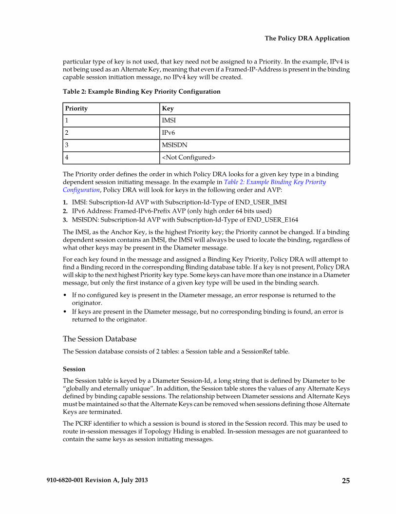
particular type of key is not used, that key need not be assigned to a Priority. In the example, IPv4 isnot being used as an Alternate Key, meaning that even if a Framed-IP-Address is present in the bindingcapable session initiation message, no IPv4 key will be created.
Table 2: Example Binding Key Priority Configuration
KeyPriority
IMSI1
IPv62
MSISDN3
<Not Configured>4
The Priority order defines the order in which Policy DRA looks for a given key type in a bindingdependent session initiating message. In the example in Table 2: Example Binding Key PriorityConfiguration, Policy DRA will look for keys in the following order and AVP:
1. IMSI: Subscription-Id AVP with Subscription-Id-Type of END_USER_IMSI2. IPv6 Address: Framed-IPv6-Prefix AVP (only high order 64 bits used)3. MSISDN: Subscription-Id AVP with Subscription-Id-Type of END_USER_E164
The IMSI, as the Anchor Key, is the highest Priority key; the Priority cannot be changed. If a bindingdependent session contains an IMSI, the IMSI will always be used to locate the binding, regardless ofwhat other keys may be present in the Diameter message.
For each key found in the message and assigned a Binding Key Priority, Policy DRA will attempt tofind a Binding record in the corresponding Binding database table. If a key is not present, Policy DRAwill skip to the next highest Priority key type. Some keys can have more than one instance in a Diametermessage, but only the first instance of a given key type will be used in the binding search.
• If no configured key is present in the Diameter message, an error response is returned to theoriginator.
• If keys are present in the Diameter message, but no corresponding binding is found, an error isreturned to the originator.
The Session DatabaseThe Session database consists of 2 tables: a Session table and a SessionRef table.
Session
The Session table is keyed by a Diameter Session-Id, a long string that is defined by Diameter to be“globally and eternally unique”. In addition, the Session table stores the values of any Alternate Keysdefined by binding capable sessions. The relationship between Diameter sessions and Alternate Keysmust be maintained so that the Alternate Keys can be removed when sessions defining those AlternateKeys are terminated.
The PCRF identifier to which a session is bound is stored in the Session record. This may be used toroute in-session messages if Topology Hiding is enabled. In-session messages are not guaranteed tocontain the same keys as session initiating messages.
25910-6820-001 Revision A, July 2013
The Policy DRA Application
Each Session record has a corresponding SessionRef record. The SessionRef provides a more compactmeans of uniquely identifying a Diameter Session-Id. This allows for a more compact Binding database.Session and SessionRef records are created and destroyed in unison.
Session Reference
SessionRef records are used to tie Binding records to Diameter sessions. This allows Policy DRA toknow when a Binding record should be removed. IMSI and MSISDN records are removed when thelast binding capable session that referenced them is removed. IP Address records are removed whenthe only binding capable session that referenced them is removed.
Because each Binding record must be associated with at least one valid Session record, a Bindingrecord can be removed if it is not associated with any existing SessionRef. Removal of orphanedBinding records is one of the jobs of the Policy DRA database audit. See Binding and Session DatabaseAuditing for more information about the database audit.
Subscriber Identification and Binding
Policy sessions can be established using multiple Diameter interfaces such as Gx, Gxx, Rx and S9. Asession can be characterized as binding capable or binding dependent, depending on whether or nota binding can be created over it.
• Gx, Gxx and S9 interfaces are binding capable• Rx and Rx over S9 interfaces are binding dependent
A session over a binding capable interface will be eligible to establish a binding to a PCRF, while asession over a binding dependent interface will rely on an existing binding to a PCRF but cannot createa new binding by itself.
In order for the Policy DRA to route all messages from a subscriber (perhaps through multiple interfacesand devices) to the same PCRF, the Policy DRA should be able to identify the subscriber by theinformation in the incoming Diameter Request messages. One subscriber can be associated withmultiple Subscriber Ids depending on the access networks and device types used. The Subscriber Idsare also called Subscriber Keys or keys. Messages that can cause creation of a subscriber-PCRF bindingare required to contain the subscriber’s device IMSI, whuch can be used to uniquely identify thesubscriber. IMSI is referred to as the subscriber Anchor Key in the Policy SBR Binding database.
Session initiating messages may also contain additional information to identify the subscriber. Thisinformation, which may include an MSISDN, an IPv4 address, or an IPv6 address prefix, is referredto as subscriber Alternate Keys. Database records with Alternate Keys are always established bybinding capable sessions, and can be used to identify the subscriber in binding dependent sessions.For example, a Gx CCR-I message must contain the IMSI Anchor Key under normal circumstance,and may also contain an MSISDN, an IPv4 address, and an IPv6 address. After a binding is establishedbetween the subscriber and a PCRF, binding dependent sessions containing one or more of thesubscriber keys can be routed to the PCRF using an Alternate Key.
In Figure 4: Subscriber Key Usage, a Gx CCR-I message created 3 subscriber keys: one Anchor Key andtwo Alternate Keys, all bound to a PCRF called PCRF5. When a binding dependent Rx session (AARmessage) is created containing only IP addresses with no Anchor Key, the Policy DRA applicationlooks up the IPv4 address of the subscriber and is able to relate it to the same PCRF because the Gxsession had defined those IP addresses.
26910-6820-001 Revision A, July 2013
The Policy DRA Application

Figure 4: Subscriber Key Usage
Alternate Keys can be configured with a priority to improve the chances of finding the data in theDiameter message and the chances of finding the Alternate Key in the Binding database. Table 3:Example Key Priority Configuration illustrates an example Binding Key configuration with prioritiesassigned to each key. The Anchor Key is mandatory in the binding capable session creation messageand is always at the top of the priority list.
Table 3: Example Key Priority Configuration
Key TypePriority
IMSI1
IPv42
MSISDN3
IPv64
<Not configured>5
The example configuration in Table 3: Example Key Priority Configuration will affect how the keys aresearched in the Diameter message for binding dependent session initiating messages:
1. After the IMSI, the Framed-IP-Address AVP will be looked for first in the incoming DiameterRequest message.
2. If the AVP is found, the Policy SBR database is searched for a binding with IPv4 address.3. If the Framed-IP-Address AVP is not found, a Subscription-Id AVP containing an MSISDN will
be looked for.4. If the Subscription-Id AVP with an MSISDN is found, look for a binding with that MSISDN.5. If a Subscription-Id AVP containing an MSISDN is not found, then no Alternate Keys are present
in the message and no Alternate Key records will be created by the application.
Only the configured subscriber keys will be searched for. For example, an incoming Diameter messagecontains a MSISDN in the Subscription-ID AVP, but MSISDN is not configured in the priorityconfiguration, the Policy DRA application will NOT look for MSISDN or use it in the Binding database.
Policy DRA Functions
The Policy DRA application performs the following major functions:
27910-6820-001 Revision A, July 2013
The Policy DRA Application
• Processing Diameter Request messages• Querying subscriber binding status• Selecting an available PCRF and routing the Diameter Requests to a selected PCRF• Topology Hiding• Processing Diameter Answer messages• Managing subscriber Session and Binding databases
Diameter Request Message ProcessingDiameter Request messages from Policy clients (PCEF, BBERF and AF) arrive at Policy DRA routedby the DSR Diameter Routing Function based on a prioritized list of Application Routing Rules. TheApplication Routing Rules are configured for the Policy DRA application based on the informationin the Diameter Request message: Application ID, Command-Code, Destination-Realm and Host, andOrigin-Realm and Host.
After receiving a Diameter Request, the Policy DRA retrieves and examines the relevant AVPs containedin the message. The AVPs relevant to the Policy DRA are those to be processed by the Policy DRA.The list of AVPs being processed by the Policy DRA is made available when the Policy DRA featureis activated. The AVPs not included in the list will not be looked at or processed by the Policy DRA.The Policy DRA-relevant AVPs vary depending on the Diameter interface on which a Diameter messageis carried.
By retrieving and examining the contents of the relevant AVPs, the Policy DRA determines:
• The type of the Diameter Request: initiation, update, or termination• The type of interface over which the Request message is carried and whether the session over this
interface is binding capable or binding dependent.
A session over a binding capable interface will be eligible to establish a binding to a PCRF, whilea session over a binding dependent interface will rely on an existing binding to a PCRF but cannotcreate a new binding by itself.
• The subscriber’s IDs from the appropriate AVPs (Subscription-ID AVP, Framed-IP-Address AVP,and Framed-IPv6-Prefix AVP)
• The Origin-Host and Realm AVPs, and Destination-Host and Realm AVPs.
The Policy DRA will use the information to query the Policy SBR database for binding and sessionstatus of the subscriber whose IDs are included in the Diameter Request message.
Emergency Session Handling
Under normal circumstance, an incoming Credit-Control Request message with Request Type as Initial(CCR-I) usually includes an AVP containing the subscriber’s IMSI. However, a CCR-I might not havean IMSI included when emergency sessions occur for various reasons; for example, the subscriber’sdevice has no SIM card in it.
The Policy DRA has capabilities to deal with these emergency sessions, by processing CCR-I messagesthat do not contain IMSI and any Alternate Keys. When a CCR-I arrives with no IMSI, the Policy DRAwill still select a configured PCRF (see Query Subscriber's Binding Status) and route the Request messageto that PCRF. If a CCA-I is received from the selected PCRF, Policy DRA will invoke the Policy SBRdatabase to create a session and binding records based on any Alternate Keys included in the message.Policy DRA then forwards the CCA-I to the Policy Client that sent the CCR-I before, subject to TopologyHiding processing for that particular Policy Client.
28910-6820-001 Revision A, July 2013
The Policy DRA Application

Query Subscriber's Binding StatusAfter processing an incoming Diameter Request message, the Policy DRA may query the Policy SBRdatabase for binding status based on the subscriber’s IDs (keys) contained in the Request message.The query is done over the Policy DRA and Policy SBR interface through the associated ComAgents.A response to the request from the Active Policy SBR to the Policy DRA provides a result on whetheror not the queried binding or session record exists in the database .
When a session initiation Request message is received over a binding capable interface (Gx, Gxx orS9), the Policy DRA will determine whether or not a binding exists for the Subscriber ID, an AnchorKey, included in the Request message. The Policy DRA queries the appropriate Policy SBR throughComAgent for the binding status for this session. Depending on the output from the interactions withthe Policy SBRs, the Policy DRA may need to select an available PCRF to which the the DiameterRequest message will be routed.
If the session initiation Request message is received from a binding dependent interface (such as Rx),the Policy DRA will check appropriate Policy SBRs to determine whether or not a binding record existsfor this subscriber.
• If a binding record exists in the database, the PCRF bound to this subscriber can be located. ThePolicy DRA will use the PCRF’s FQDN to route the Diameter Request message to it.
• If a binding record does not exist for this subscriber, the Policy DRA will check the Topology Hidingstatus for this Policy Client.
• If Topology Hiding is NOT applicable, the Policy DRA will route the Request message basedon the Destination-Host AVP, if present in the Request message, or send an Answer messagewith an error to the originator of the message, if the Destination-Host AVP is not present in theRequest message.
• If Topology Hiding is applicable for this message, the Policy DRA will look for a session forthis subscriber.
If such a session exists, the Policy DRA will route the Request message by using the PCRFinformation found in the session record.
Otherwise, the Policy DRA will either route the Request message based on the Destination-HostAVP, if included in the AAR, or send an Answer message with an error to the originator of themessage, if the Destination-Host AVP is not present in the Request message message.
PCRF Selection and RoutingPCRF selection involves distribution of subscriber bindings to PCRFs that are configured in advance.When a Diameter Request message arrives on a Gx, Gxx, or S9 interface aiming at generating a newsession, the Policy DRA must determine if a binding already exists for the IMSI included in theSubscription-Id AVP of the Diameter message, and starts to select the PCRF then.
In Figure 5: Policy DRA PCRF Selection Concepts, four Policy DRA DSRs are located at four geographicalsites. The Policy DRA DSRs at Sites 1 and 2 are configured to be mated, and the Policy DRA DSRs atSites 3 and 4 are mated. Each site has a group of Policy clients (PCEFs in the figure) and a group ofPCRFs connecting to the Policy DRA in the same site, the primary Policy DRA connection. The Policyclients and PCRFs also have a secondary connection to another Policy DRA DSR that is the mate ofthe local Policy DRA DSR. This relationship is illustrated by the solid blue lines shown at Site 1 andSite 2.
29910-6820-001 Revision A, July 2013
The Policy DRA Application

When PCRF selection occurs for a request arriving at Policy DRA DSR 1 at Site 1, only the PCRFs localto Policy DRA DSR 1 (PCRF 1 and PCRF 2 in Figure 5: Policy DRA PCRF Selection Concepts) are candidatesfor the new subscriber binding. If the Policy DRA at DSR1 knows that none of its local PCRFs areconfigured, the session initiating message is forwarded by Policy DRA to the mate Policy DRA DSR.The process of PCRF selection then occurs at the Site 2 Policy DRA DSR, with Policy DRA DSR 2selecting from PCRF 3 and PCRF 4. If no PCRF is configured at Site 2 either, the binding attempt fails.Diameter loop prevention prohibits Policy DRA DSR 2 from routing the message to its mate becausethe message has already visited Policy DRA DSR 1.
Figure 5: Policy DRA PCRF Selection Concepts
The Policy DRA application accomplishes the PCRF selection by performing a simple round-robindistribution across the configured PCRFs. After a binding is successfully established between thesubscriber and the selected PCRF, all Diameter messages to that subscriber, either binding capable orbinding dependent, must be routed to that specific PCRF regardless of where in the network thosemessages are initiated. This subscriber binding persists until the last binding capable session for thatsubscriber is terminated.
Topology Hiding ProcessFor security reasons, network operators require the Diameter Routing Agents to be able to hide thePCRF topology from selected Policy Clients. When a Policy Client is configured to have the PCRFtopology hidden from it, all Diameter messages (Request or Answer) that are sent to it need to beprocessed by the Policy DRA for Topology Hiding. The Policy DRA will place some configuredOrigin-Host and Origin-Realm values into the messages instead of the PCRF’s real Origin-Host andOrigin-Realm values.
Topology Hiding configuration is done on each Policy DRA DSR using the Policy DRA GUI. Theconfiguration enables users to set the Topology Hiding function to be Enabled or Disabled for thePolicy DRA node. After being enabled, the Topology Hiding function can be further configured to
30910-6820-001 Revision A, July 2013
The Policy DRA Application

apply for a specific Topology Hiding Scope, as summarized in Table 4: Topology Hiding ScopeConfiguration:
• The Policy Clients with specific FQDNs• All of the Policy Clients with Foreign Realm• All the Policy Clients with Foreign Realm and the local Policy Clients with specific FQDNs• All Policy Clients
The Host Name used for hiding PCRF topology is also configured. If a Policy Client is configured touse Topology Hiding, the Origin Host and Realm of all messages sent to the Policy Client will bechanged to the configured Host Name.
The Diameter messages to be topology hidden from certain Policy Clients can be initiated from eitherPolicy Clients (by a CCR from a PCEF) or Policy servers (by an RAR from a PCRF), or initiated by thePolicy DRA (by an RAR generated by the Policy DRA). The handling of the Diameter messages forTopology Hiding will be different depending on the specific scenarios. To determine whether or notTopology Hiding is applicable for a Policy Client:
• For messages initiated from Policy Clients, the Policy DRA will compare the Origin-Host andOrigin-Realm values in the incoming messages to the configured values.
• For messages initiated from Policy servers or by the Policy DRA, the Policy DRA compares theDestination-Host and Destination-Realm values to the configured values.
• For messages initiated by the Policy DRA, the Policy DRA will compare the Destination-Host andDestination-Realm of the Policy Client with the configured values to determine whether or not theTopology Hiding is applicable to the Policy Client.
Table 4: Topology Hiding Scope Configuration
ResultTopology Hiding ScopeSetting
Topology HidingSystem Setting
No Topology Hiding is performedN/ADisabled
Topology Hiding is performed for messagesdestined for the Policy Clients only if the Policy
Specific HostsEnabled
Clients’ FQDNs are configured for TopologyHiding
Topology Hiding is performed for messagesdestined for the Policy Clients if the realms of the
All Foreign Realms
Policy Clients are different from the Realm of thePCRF that sends the messages
Superset of All Foreign Realms and Specific Hostsoptions
All Foreign Realms + SpecificHosts
Topology Hiding is performed for all messagesdestined to all Policy Clients
All Messages
Diameter Answer Message ProcessingAfter the Policy DRA routes a Diameter Request message to a selected PCRF, and updates the PolicySBR on binding status, the Policy DRA could find itself in one of the following situations:
31910-6820-001 Revision A, July 2013
The Policy DRA Application
1. An Answer is received from a PCRF and a response is received from a Policy SBR2. An Answer is received from a PCRF, but no response is received from a Policy SBR after a configured
time interval3. A response is received from a Policy SBR, but no Answer is received after a configured time interval
For situations 1 and 2, the Policy DRA always forwards the Answer messages to the correspondingRequests initiators through the Diameter Routing Function, with or without Topology Hiding processingdepending on the Topology Hiding status of the Policy Client.
For situation 3, the Policy DRA generates Diameter Answer messages with proper Error Codes androutes the Answers to the Request initiators through the Diameter Routing Function, with or withoutTopology Hiding processing depending on the Topology Hiding status of the Policy Client.
Subscriber Session and Binding Database ManagementThe Policy DRA will invoke the Policy SBRs to perform relevant database operations after or in parallelwith sending the Answer messages out. Which database operations to be performed depends on theDiameter interface type in the incoming Diameter Request, the Diameter Request message type (sessioninitiation, session update, or session termination), and the results from the responses. The followingoperations can be performed:
• Finding, creating, or updating binding records• Removing Suspect Binding records• Creating or removing alternate key binding records• Finding, creating, refreshing, or removing session records
Policy DRA Session IntegrityThe Policy DRA application provides a capability called "Session Integrity" that addresses two potentialproblems:
1. Session Audit Premature Removal of Sessions
Policy DRA uses the mechanism of the Session Audit (see Binding and Session Database Auditing),by which session-related resources can be freed in the event that the session is not torn downproperly by Diameter signaling.
Session state synchronization between Policy DRA and Policy Client for binding capable sessionsprevents the Session Audit (see Binding and Session Database Auditing) from removing valid sessionsthat could be considered as “stale” .
If the Policy DRA simply removed a binding capable session that it considered to be stale, any keysassociated with that session would also be removed. This in turn would cause binding dependentRx sessions that rely on those keys to fail. The Policy Client and PCRF have no idea that there is aproblem with the binding capable session and therefore will not re-create it, causing the sessionand keys to be added back to the Policy DRA database.
Instead of just removing a session that could be considered to be stale, Policy DRA queries thePolicy Client. If the Policy Client responds indicating that the session is valid, Policy DRA waitsfor an interval of time before the session can be considered to be stale again. If the Policy Clientresponds indicating that the session is unknown, the Policy DRA will remove its session and freeall resources associated with the session, including any keys that the session created.
2. Incomplete Session Data
32910-6820-001 Revision A, July 2013
The Policy DRA Application

In order to reduce Diameter signaling latency for policy signaling, Policy DRA attempts to relayDiameter messages before updating its various database tables. Provided that all database updatesare created successfully and in a timely manner, this works very well. There are scenarios in whichrecords cannot be successfully updated and the Policy Client and the PCRF are not aware of anyproblem. Table 5: Policy DRA Error Scenarios for Session Integrity describes specific scenarios wherePolicy DRA record creation failure can occur and the consequences of the failures for policy signaling.
In the case in which Policy DRA fails to create a binding record when a binding capable session iscreated, Policy DRA has already relayed the CCA-I message back to the PCEF (to reduce latency).The PCEF is unaware that one of the binding keys that it requested to be correlated with thesubscriber's session does not exist in the Policy DRA. When a binding dependent Rx session attemptsto use the failed binding key, the Rx session will fail because Policy DRA does not know whichPCRF it should be routed to.
Incomplete or incorrect binding capable session data could persist for days because binding capablesessions can last as long as the UE (the subscriber's phone) is powered up and attached to thenetwork. The PCEF that set up the binding capable session does not know that there is any problemwith the correlation keys.
The solution for incomplete or incorrect data in the P-DRA is to compel the PCEF to tear down andreestablish the binding capable session in hopes that all P-DRA data updates will be createdsuccessfully on the next attempt. This is accomplished by P-DRA sending an RAR messagecontaining a Session-Release-Cause AVP indicating that the session should be torn down.
Table 5: Policy DRA Error Scenarios for Session Integrity describes the specific scenarios in which thePolicy DRA Session Integrity mechanism is required to remove a broken session. The first scenariois included to describe why Session Integrity does not apply to creation of an IMSI Anchor Key fora new binding.
Table 5: Policy DRA Error Scenarios for Session Integrity
Policy DRA BehaviorError Scenario
Because the CCR-I has not yet been forwarded to the PCRF,this scenario can be handled by sending a failure Answer to
Failed to create IMSI Anchor Keyfor new binding
the Policy Client in the CCA-I response. In this case, no sessionis ever established.
The Policy Client will attempt to re-establish the bindingcapable session.
By the time Policy DRA creates a session record, the CCA-Ihas already been relayed to the Policy Client. If the session
Failed to create binding capablesession
record cannot be created, no Alternate Keys are created. PolicyDRA must cause the Policy Client to terminate the bindingcapable session (and re-create it).
If the session record is not created, and no Alternate Keys arecreated, a binding dependent session that needs to use thosekeys will fail.
By the time Policy DRA creates an alternate key record, theCCA-I has already been relayed to the Policy Client. If the
Failed to create an alternate key
33910-6820-001 Revision A, July 2013
The Policy DRA Application
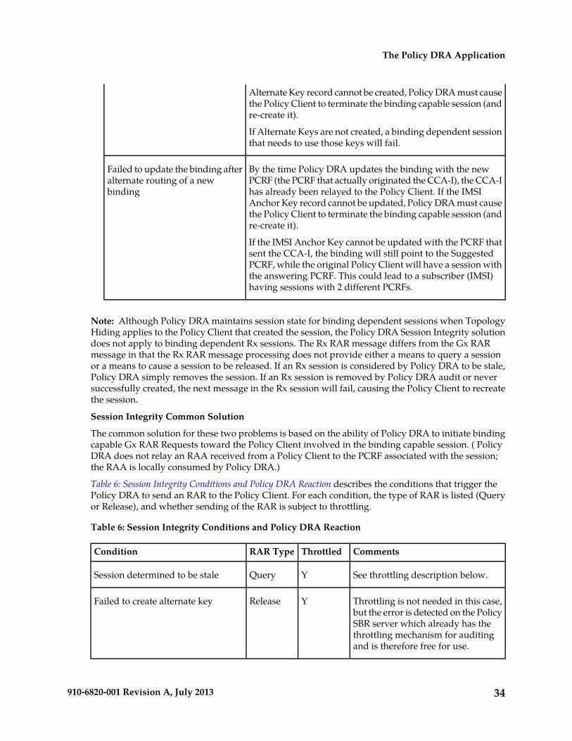
Alternate Key record cannot be created, Policy DRA must causethe Policy Client to terminate the binding capable session (andre-create it).
If Alternate Keys are not created, a binding dependent sessionthat needs to use those keys will fail.
By the time Policy DRA updates the binding with the newPCRF (the PCRF that actually originated the CCA-I), the CCA-I
Failed to update the binding afteralternate routing of a newbinding has already been relayed to the Policy Client. If the IMSI
Anchor Key record cannot be updated, Policy DRA must causethe Policy Client to terminate the binding capable session (andre-create it).
If the IMSI Anchor Key cannot be updated with the PCRF thatsent the CCA-I, the binding will still point to the SuggestedPCRF, while the original Policy Client will have a session withthe answering PCRF. This could lead to a subscriber (IMSI)having sessions with 2 different PCRFs.
Note: Although Policy DRA maintains session state for binding dependent sessions when TopologyHiding applies to the Policy Client that created the session, the Policy DRA Session Integrity solutiondoes not apply to binding dependent Rx sessions. The Rx RAR message differs from the Gx RARmessage in that the Rx RAR message processing does not provide either a means to query a sessionor a means to cause a session to be released. If an Rx session is considered by Policy DRA to be stale,Policy DRA simply removes the session. If an Rx session is removed by Policy DRA audit or neversuccessfully created, the next message in the Rx session will fail, causing the Policy Client to recreatethe session.
Session Integrity Common Solution
The common solution for these two problems is based on the ability of Policy DRA to initiate bindingcapable Gx RAR Requests toward the Policy Client involved in the binding capable session. ( PolicyDRA does not relay an RAA received from a Policy Client to the PCRF associated with the session;the RAA is locally consumed by Policy DRA.)
Table 6: Session Integrity Conditions and Policy DRA Reaction describes the conditions that trigger thePolicy DRA to send an RAR to the Policy Client. For each condition, the type of RAR is listed (Queryor Release), and whether sending of the RAR is subject to throttling.
Table 6: Session Integrity Conditions and Policy DRA Reaction
CommentsThrottledRAR TypeCondition
See throttling description below.YQuerySession determined to be stale
Throttling is not needed in this case,but the error is detected on the Policy
YReleaseFailed to create alternate key
SBR server which already has thethrottling mechanism for auditingand is therefore free for use.
34910-6820-001 Revision A, July 2013
The Policy DRA Application
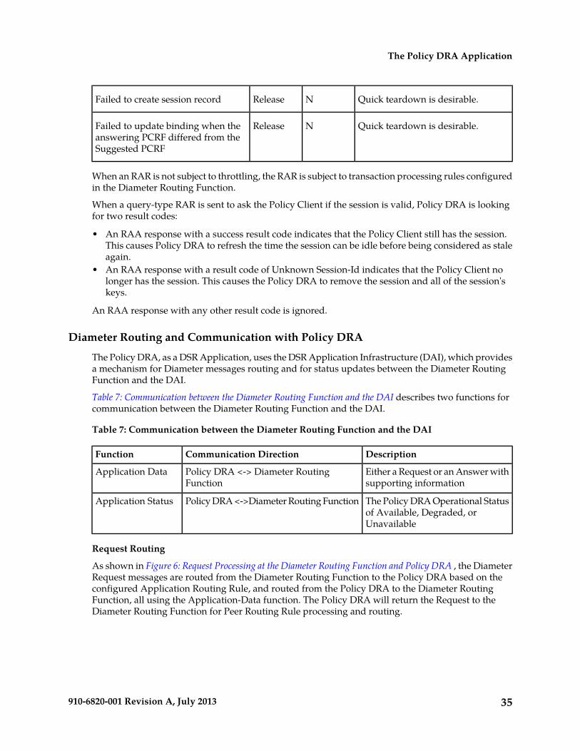
Quick teardown is desirable.NReleaseFailed to create session record
Quick teardown is desirable.NReleaseFailed to update binding when theanswering PCRF differed from theSuggested PCRF
When an RAR is not subject to throttling, the RAR is subject to transaction processing rules configuredin the Diameter Routing Function.
When a query-type RAR is sent to ask the Policy Client if the session is valid, Policy DRA is lookingfor two result codes:
• An RAA response with a success result code indicates that the Policy Client still has the session.This causes Policy DRA to refresh the time the session can be idle before being considered as staleagain.
• An RAA response with a result code of Unknown Session-Id indicates that the Policy Client nolonger has the session. This causes the Policy DRA to remove the session and all of the session'skeys.
An RAA response with any other result code is ignored.
Diameter Routing and Communication with Policy DRA
The Policy DRA, as a DSR Application, uses the DSR Application Infrastructure (DAI), which providesa mechanism for Diameter messages routing and for status updates between the Diameter RoutingFunction and the DAI.
Table 7: Communication between the Diameter Routing Function and the DAI describes two functions forcommunication between the Diameter Routing Function and the DAI.
Table 7: Communication between the Diameter Routing Function and the DAI
DescriptionCommunication DirectionFunction
Either a Request or an Answer withsupporting information
Policy DRA <-> Diameter RoutingFunction
Application Data
The Policy DRA Operational Statusof Available, Degraded, orUnavailable
Policy DRA <->Diameter Routing FunctionApplication Status
Request Routing
As shown in Figure 6: Request Processing at the Diameter Routing Function and Policy DRA , the DiameterRequest messages are routed from the Diameter Routing Function to the Policy DRA based on theconfigured Application Routing Rule, and routed from the Policy DRA to the Diameter RoutingFunction, all using the Application-Data function. The Policy DRA will return the Request to theDiameter Routing Function for Peer Routing Rule processing and routing.
35910-6820-001 Revision A, July 2013
The Policy DRA Application

Figure 6: Request Processing at the Diameter Routing Function and Policy DRA
Answer Routing
When the Policy DRA forwards a Request message to the Diameter Routing Function for routing, itmust inform the Diameter Routing Function how to process the corresponding Answer. It can informthe Diameter Routing Function either to route the Answer to the Policy DRA or to route the Answerto the downstream Peer without involving the Policy DRA. Figure 7: Answer Processing at the DiameterRouting Function and Policy DRA shows the case where an Answer is transmitted back to the PolicyDRA. After the Policy DRA completes processing of the Answer, it will send it to the Diameter RoutingFunction for transmission to the Diameter Transport Function so that it can be routed to the downstreamPeer.
Figure 7: Answer Processing at the Diameter Routing Function and Policy DRA
Policy DRA Generated Answer
In some cases, the Policy DRA needs to generate an Answer message in response to an incomingRequest. For example, the Policy DRA cannot find a PCRF to route the Request message to. Figure 8:Policy DRA Generated Answer Routing shows the Diameter Routing Function routing for this scenario.
36910-6820-001 Revision A, July 2013
The Policy DRA Application

Figure 8: Policy DRA Generated Answer Routing
Policy DRA Generated Request
In some cases, the Policy DRA needs to generate Diameter Requests. Figure 9: Policy DRA GeneratedRequest Routing shows the Diameter Routing Function routing for this scenario.
Figure 9: Policy DRA Generated Request Routing
Policy DRA Application Use Cases
The following typical Policy DRA application signaling use cases demonstrate the Policy DRA andPolicy SBR capabilities to establish subscriber binding to some PCRF, and update and terminate thesessions when requested:
• Binding and Session Creation and Session Termination over the Gx Interface - A Policy Clientrequests to bind a subscriber for policy provisioning over a Gx interface. The Policy DRA createsthe binding to a selected PCRF, generates the binding and session records in the Policy SBR database,updates the session as requested, and eventually terminate session as requested.
• Subscriber Session Creation and Termination over the Rx Interface - A Diameter Request is sentto the Policy DRA over the Rx interface for the same subscriber that has established a binding with
37910-6820-001 Revision A, July 2013
The Policy DRA Application

the PCRF over the Gx interface. The Policy DRA coordinates the sessions over the Gx and Rxinterfaces and routes the Diameter messages to the same PCRF.
• Policy DRA in Roaming Scenarios - In addition to communicating to the Policy Clients and Policyservers through Gx/Gxx and Rx interfaces in their own networks, the Policy DRAs can communicateto each other across the Visited Access and Home Access networks through the S9 interface, forsession binding purposes. See Policy DRA in Roaming Scenarios.
Ingress RoutingThis section describes how Diameter Request and Answer messages are routed to Policy DRA.
Requests
Diameter Routing for Requests checks three conditions to determine whether to route a Request to aDSR Application:
1. Does the Request include a DSR-Application-Invoked AVP, indicating that the Request has alreadybeen processed and should not be processed again by a DSR Application?
If this AVP is present, the Request will not be routed to any DSR Application. Otherwise, the nextcondition is checked.
2. Does the Request match an Application Routing Rule?
If no rule is matched, the Request is not routed to any DSR Application. Otherwise, the nextcondition is checked.
3. If the Request matches an Application Routing Rule, is the DSR Application Operational Statusfor this DA-MP set to Available?
If the DSR Application is not Available, then the “Unavailability action” is performed by Diameter.For Policy DRA, the Unavailability action is “Continue Routing”, which means to route the Requestusing PRT Peer Routing Rules.
If the DSR Application is Available, then Diameter routes the Request to the DSR Applicationspecified in the matching Application Routing Rule.
Ingress Requests are examined by Diameter to determine whether they should be routed to a DSRApplication. The rules for deciding how to route ingress Requests are defined in Diameter ConfigurationApplication Routing Rules. Table 8: Policy DRA Application Routing Rule Configuration describes theexpected configuration of Application Routing Rules for Policy DRA. These rules will cause everyRequest that includes one of these values in the Application-Id in the Diameter Header to be routedto the Policy DRA application. Some of these rules can be omitted, depending on which interfaces areused for Policy DRA.
• The Rule Name can be any name that is chosen to identify the rule.• The Priority is a value from 1 to 99, where 1 is the highest Priority. Rules with higher Priority will
be evaluated for matching before rules with lower Priority. Rules that overlap (one rule is morespecific than another) can use the Priority field to remove ambiguity about which rule should bechosen. ("Best Match" semantics is not supported for Application Routing Rules.)
• Conditions can include Destination-Realm, Destination-Host, Application-Id, Command Code,Origin-Realm, and Origin-Host. If more than one condition is specified, the conditions are logicallyANDed together to determine if a rule is matched.
• The Application Name is always PDRA for the Policy DRA application. PDRA appears in theApplication Name pulldown list only if the Policy DRA feature has been activated.
38910-6820-001 Revision A, July 2013
The Policy DRA Application

Table 8: Policy DRA Application Routing Rule Configuration
ApplicationName
ConditionsPriorityRule Name
PDRAAppId Equal 16777238 - 3GPP Gx1P-DRA Gx
PDRAAppId Equal 16777236 - 3GPP Rx1P-DRA Rx
PDRAAppId Equal 16777267 - 3GPP S91P-DRA S9
PDRAAppId Equal 16777266 - 3GPP Gxx1P-DRA Gxx
Answers
Diameter Answer messages can be routed to a DSR Application, or relayed by Diameter using PeerRouting Rules. Table 9: Answer Processing by Policy DRA lists all of the supported Answer messagesand indicates which ones are processed by Policy DRA under what conditions.
If the Policy DRA application has requested to receive an Answer, but the Policy DRA application hasOperational Status of Unavailable, the Diameter Routing Function will relay the Answer messagedirectly to the remote Peer.
Note: Relaying an Answer while the Policy DRA application is Unavailable might result in exposinga PCRF name that was supposed to be topology hidden. This is because Diameter Routing does notsupport configuration of whether to relay or discard Answers when a DSR Application requestedreceipt of the Answer, but became Unavailable before the Answer was received.
Table 9: Answer Processing by Policy DRA
ConditionRequested by Policy DRAAnswer
N/AAlwaysCCA-I
CCA-U is processed by PolicyDRA only if Policy DRA is
ConditionalCCA-U
configured to update the SessionLast Touched Time on CCA-Uin addition to RAA.
N/AAlwaysCCA-T
N/AAlwaysRAA (Gx)
N/AAlwaysAAA
N/ANeverASA
N/AAlwaysRAA (Rx)
N/AAlwaysSTA
Egress RoutingThis section describes how Diameter Request messages are routed from Policy DRA. Diameter Requestmessages are routed from the Diameter Routing Function to the Policy DRA based on the configured
39910-6820-001 Revision A, July 2013
The Policy DRA Application
Application Routing Rule, and routed from the Policy DRA to the Diameter Routing Function. ThePolicy DRA will return the Request to the Diameter Routing Function for PRT processing and routing.
When the Policy DRA forwards a Request message to the Diameter Routing Function for routing, itmust inform the Diameter Routing Function how to process the corresponding Answer. It can informthe Diameter Routing Function to either route the Answer to the Policy DRA or route the Answer tothe downstream Peer without involving the Policy DRA. After the Policy DRA completes processingof the Answer, it will send it to the Diameter Routing Function for transmission to the DiameterTransport Function so that it can be routed to the downstream Peer. Egress Answer messages arealways routed according to the Connection-Id and Diameter Hop-By-Hop-Id of the Request they areanswering.
PCRF Selection for New Bindings
When a binding capable session initiation message (CCR-I) arrives for an IMSI that is not alreadybound to a PCRF, the Policy DRA application selects a PCRF from the list of adjacent PCRFs that areconfigured using the Policy DRA -> Configuration -> PCRFs GUI page This list of PCRFs generallycontains only PCRFs that are local to the Site with the Policy DRA node. PCRFs that are local to thePolicy DRA node’s mate are generally not be included. The reason to include only local PCRFs is toavoid the extra latency associated with selection of a PCRF separated across a WAN from the PolicyClient that initiated the session.
If the PCRF has different Hostnames for different 3GPP interfaces (Gx, Rx, Gxx, S9), only the bindingcapable Hostnames are configured in the Policy DRA -> Configuration -> PCRFs GUI.
Policy DRA distributes new bindings across the set of configured PCRFs. The distribution occursindependently on each DA-MP server; predicting the next PCRF that will be used is difficult on aPolicy DRA node that has Policy Client connections to multiple DA-MP servers. In addition, thedistribution is determined for each CCR-I received, causing the next PCRF to be updated even if theCCR-I is for a subscriber that already has a binding.
It is also possible to support more complicated PCRF selection by pushing the PCRF selection intoDiameter Routing and out of the Policy DRA application. This can be accomplished by configuring aseparate Peer Routing Table to be used for new binding creations using the Policy DRA ->Configuration -> Site Options GUI. The Peer Routing Rules can be configured to cause selection ofdifferent Route Lists. In this mode, Policy DRA can support weighted PCRF selection and differentPCRF pools based on the origin of the Request.
PCRF Selection for Existing Bindings
A binding becomes finalized when a successful CCA-I is received from a PCRF for a given subscriber.At this point, all Policy sessions for that subscriber must be routed to that PCRF Peer Node, or a PeerNode that shares state with the bound Peer Node. The subscriber remains bound to this PCRF untilall of the subscriber’s binding capable sessions (Gx, Gxx, S9) are terminated.
The architecture for many PCRFs is such that a single Diameter host is not a single point of failure fora subscriber’s Policy sessions. This is generally accomplished by designating a set of Diameter hoststhat all share a common database and can therefore all access the subscriber’s Policy data and Resourceusage.
If the PCRF supports multiple Diameter hosts that share state, routing can be set up as follows:
• A Peer Routing Rule that matches the Destination-Host equal to the bound PCRF name• A Route List that has a Primary and a Secondary Route Group
• The Primary Route Group routes only to the bound PCRF
40910-6820-001 Revision A, July 2013
The Policy DRA Application
• The Secondary Route Group distributes across all PCRF Peers that share state with the boundPCRF.
Some PCRFs also have different Diameter hosts for different 3GPP interfaces. For example, they mayhave a hostname for Gx and a different hostname for Rx. This can be accommodated by creating twoPeer Routing Rules as follows:
• A Peer Routing Rule that matches the Destination-Host equal to the bound PCRF name andApplication-Id equal to Gx (16777238).
• A Peer Routing Rule that matches the Destination-Host equal to the bound PCRF name andApplication-Id equal to Rx (16777236).
Routing In-Session Messages Without Topology Hiding
When the PCRF name is not topology hidden, the Policy Client is expected to learn the PCRF namefrom the Origin-Host and Origin-Realm of the Answer to the session initiation Request (CCA-I orAAA). This PCRF name is used as the Destination-Host and Destination-Realm of all subsequentin-session Requests originated by the Policy Client.
Policy Clients that are proxy-compatible (can learn the PCRF name) allow Policy DRA to host-routein-session Requests without the need for any Binding or Session database lookup. This behavior isdesirable because it reduces the number of Policy SBR servers needed to support a given Diametertraffic load.
There are, however, Policy Clients that are not proxy-compatible. Many of these always omit theDestination-Host AVP from Requests, or include the Destination-Host AVP with the Policy DRADiameter hostname. In order to support such Policy Clients, Policy DRA must be configured to addor replace the Destination-Host and Destination-Realm of all Requests with the PCRF that the subscriberis bound to. Policy Clients that are not proxy-compatible can also be accommodated by enablingTopology Hiding.
Routing In-Session Message with Topology Hiding
When topology hiding is enabled, the PCRF name is hidden from the applicable Policy Client. Referto Policy DRA online help for Topology Hiding Scope options. If the PCRF name is hidden from thePolicy Client, the Policy Client cannot use the PCRF as the Destination-Host and Destination-Realmin its in-session Requests. When Topology Hiding is in force for a Policy Client, Policy DRA mustroute in-session Requests to the bound PCRF by performing a Session record lookup and using thePCRF information stored in the Session record.
Use of topology hiding requires increased stack event processing and increased latency to look up thebound PCRF in the Session record. For these reasons, Topology Hiding should have the narrowestpossible Scope. For example, if topology should be hidden from only a few Policy Clients, choose theper-Policy Client Topology Hiding Scope instead of choosing to hide topology from all Policy Clients.
Topology Hiding can also be used to “work around” a Policy Client that does not have the ability tolearn the PCRF name (that is not proxy-compatible).
Naming Conventions and Hierarchical Routing
When Policy DRA is deployed in large networks with multiple Policy DRA mated pairs, the DiameterRouting configuration can be greatly simplified by employing some simple naming conventions. Forexample, naming all Policy Clients and PCRFs local to a particular Policy DRA node such that theystart with a common prefix allows Peer Routing Rules like “Destination-Host Starts-With xxx”, where
41910-6820-001 Revision A, July 2013
The Policy DRA Application
xxx is the Site prefix for that Policy DRA node. The “Starts-With” rule will point to a Route List thatroutes to the Policy DRA node where the equipment is located. Then if a new Policy Client or PCRFis added at a given Policy DRA node, routing changes are needed only at that node and that node’smate, which have Peer Node entries and Diameter connections (that is, are adjacent) to the new PolicyClient or PCRF. Policy DRA nodes that are non-adjacent do not require any routing updates.
Policy DRA Assumptions and Limitations
Policy DRA has the following assumptions and limitations:
Assumptions
• The Anchor Key that identifies all subscribers in the Policy DRA network is the IMSI.• All Gx and Gxx session initiating Diameter messages will always include the IMSI. The only
exception is emergency calls from devices with no SIM card (UICC-less).• Messages sharing a common Diameter Session-Id will never arrive out of sequence.• PCRF names and Policy Client names start with characters that can be used to identify which Policy
DRA DSR hosts the primary connection to that equipment. This greatly simplifies routingconfiguration for the Policy DRA network. The network can be configured to work without sucha naming convention, but routing setup and maintenance will be unnecessarily complex.
Limitations
• When a PCRF is selected for a new subscriber binding, a simple round-robin selection mechanismis employed. Policy DRA PCRF selection can be overridden by DSR routing configuration. WhenPCRF selection is overridden by DSR, weighted load distribution can also be used.
• Quota pooling is not supported. Quota pooling is a feature that would allow a number of subscribersto share a common pool of resources for Policy decisions. For example, a family plan where allmembers of the family share access to resources such as bandwidth. Policy DRA has no mechanismfor identifying members of a quota pool such that their sessions could all be routed to the samePCRF.
• Policy data Binding records are guaranteed to survive only a single site failure.• Policy DRA does not support the 3GPP mechanism to redirect Policy Clients to a PCRF.• Policy DRA does not support growth of Policy SBR resources. A Policy DRA system can be
configured at activation time to be as small as 3 servers, or as large as 8 Policy DRA mated pairsof 3 enclosures each, but once the number of Policy SBR(B) Server Groups per network and thenumber of Policy SBR(S) Server Groups per mated pair is chosen at feature activation time, neithergrowth nor de-growth is supported without first deactivating the feature. Feature deactivationrequires a total network-wide outage for Policy DRA. (Additional mated pairs can, however, beadded to grow the Policy DRA network provided that the new mated pairs have the same numberof session Policy SBR Server Groups as the existing mated pairs.)
• Policy DRA supports only two of the Diameter Subscription-Id types: END_USER_IMSI (for IMSI)and END_USER_E164 (for MSISDN). Any other Subscription-Id type is ignored.
• Policy DRA evenly distributes new sessions across the Policy Session Policy SBR Server Groups atthe mated pair, regardless of the physical location of the Active server. This results in ~50% ofsession accesses traversing the WAN between the mated pair sites.
42910-6820-001 Revision A, July 2013
The Policy DRA Application
Chapter
3Policy DRA Deployment
Policy DRA can be deployed in customer networksto solve Policy Diameter signaling routing issues.
Topics:
• High Level Deployment Description.....44A Policy DRA DSR consists of a number of PolicyDRA DA-MPs, a number of Policy SBRs, OAMservers, and IPFE servers.
• Deployment Topology.....44• Redundancy.....59• Policy DRA Scalability.....64• IP Networking.....68
43910-6820-001 Revision A, July 2013
High Level Deployment Description
A Policy DRA DSR consists of a number of Policy DRA DA-MPs, a number of Policy SBRs, OAMservers, and optional IPFE servers.
The Policy DRA DA-MPs are responsible for handling Diameter signaling the Policy DRA application.
Policy SBRs are special purpose MP blades that provide an off-board database for use by the PolicyDRA eature hosted on the Policy DRA DA-MPs. Policy SBRs host the Policy session and Policy Bindingdatabases.
Each Policy DRA DSR hosts connections from Policy Clients and PCRFs. Policy Clients are devices(not provided by Tekelec) that request authorization for access to network resources on behalf of userequipment (such as mobile phones) from the PCRF. Policy Clients sit in the media stream and enforcePolicy rules specified by the PCRF. Policy authorization requests and rules are carried in Diametermessages that are routed through Policy DRA. Policy DRA makes sure that all Policy authorizationrequests for a given subscriber are routed to the same PCRF.
Policy DRA DSRs can be deployed in mated pairs such that Policy session state is not lost even if anentire Policy DRA DSR fails or becomes inaccessible. When Policy DRA mated pairs are deployed,Policy Clients and PCRFs are typically cross-connected such that both Policy DRA DSRs haveconnections to all Policy Clients and all PCRFs at both mated sites.
“Policy DRA network” is the term used to describe a set of Policy DRA mated pairs and NOAM serverpair. All Policy Clients and PCRFs are reachable for Diameter signaling from any Policy DRA DSR inthe Policy DRA network.
Deployment Topology
This section describes the makeup of a Policy DRA network, regardless of its size. Figure 10: Sites,Mated Pairs, and Region illustrates an example Policy DRA network.
• A Policy DRA Network can have up to 8 mated pairs or 16 sites, or can be as small as a single site.• The Policy DRA Binding Region provides the scope of the Policy Binding database. There is one
instance of the Binding database in the entire Policy DRA network. Binding records are accessiblefrom every Policy DRA DSR in the Region.
The Binding database need not be confined to a single mated pair, but can be deployed acrossmultiple Policy DRA DSRs. All Policy Binding Server Groups must be deployed before the PolicyDRA network can be used.
• Mated Pair provides the scope for an instance of the Policy Session database.
There is one instance of the Session database per Policy DRA Mated Pair. Session records areaccessible from each Policy DRA DSR in the Mated Pair.
• Policy Clients and PCRFs have primary connections to their local Policy DRA and secondaryconnections to the mate of their local Policy DRA.
• Policy DRA DSRs are connected to each other on the External Signaling Network. Each Policy DRASite must be reachable from every other Policy DRA Site in the Region for Diameter signaling.
44910-6820-001 Revision A, July 2013
Policy DRA Deployment

• The External Signaling Network handles Stack Events, database replication, and Diameter signaling.All three are required for the Diameter signaling to function correctly and with the required levelof redundancy. “Services” (configured using the Configuration->Services GUI page) can be usedto enforce separation of different types of traffic.
Figure 10: Sites, Mated Pairs, and Region
See Policy DRA Scalability for details on how the Policy DRA feature can scale from very small lab andtrial systems to large multi-site deployments.
If the deployment includes more than one mated pair, all mated pairs that host the Binding databasemust be deployed before the Policy DRA network can be functional. Subsequent mated pairs can bedeployed as needed, but will host only instances of the Session database.
45910-6820-001 Revision A, July 2013
Policy DRA Deployment

Policy DRA in Roaming Scenarios
3GPP has defined two roaming scenarios with respect to Policy Control and Charging functions. ThePolicy DRA can be deployed for various network scenarios as a Policy routing agent, including theroaming scenarios.
In addition to communicating to the Policy Clients and Policy servers through Gx/Gxx and Rx interfacesin their own networks, the Policy DRAs can communicate to each other across the Visited Access andHome Access (or Home Routed Access) networks through the S9 interface, for session binding purposes.
Figure 11: Policy DRA in Roaming Scenarios illustrates an example Diameter network where the PolicyDRAs are located in Home Access and Visited Access networks.
Figure 11: Policy DRA in Roaming Scenarios
The Visited Access (also known as Local Breakout) is one of the scenarios where UEs obtain access tothe packet data network from the VPLMN where the PCEF is located.
The Home Routed Access is the roaming scenario in which the UEs obtain access to the Packet DataNetwork from the HPLMN where the PCEF is located.
The S9 reference point is defined in roaming scenarios between HPLMN and VPLMN over which twoDiameter applications, S9 and Rx are used. The purpose of the S9 Diameter application is to installPCC or QoC rules from the HPLMN to the VPLMN and transport the events occurred in the VPLMNto the HPLMN.
46910-6820-001 Revision A, July 2013
Policy DRA Deployment

The S9 protocol makes use of exactly the same commands and messages as the Gx/Gxx protocols,except that a V-PCRF in VPLMN will provide an emergency treatment for any incoming CC-Request(INITIAL_REQUEST) messages. This implies that the Policy DRA does not check the existence of theCalled-Station-ID AVP if the IMSI is missing in a CC-Request (INITIAL_REQUEST) over the S9interface.
Policy DRA Configurable Components
Figure 12: Policy DRA Component Relationships illustrates the relationships between the following keyPolicy DRA configurable components:
• Policy DRA Binding Region - consisting of all Policy DRA Sites• Policy DRA Mated Pairs - consisting of pairs of Policy DRA Sites• Policy DRA Sites• Policy Session Resource Domains – one per Policy DRA Mated Site consisting of all Session Policy
SBR Server Groups at the mated pair• Policy Binding Resource Domain – one per Policy DRA Binding Region consisting of all Binding
Policy SBR Server Groups• Policy DRA Resource Domains – one per Policy DRA Mated Site consisting of all DSR (multi-active
cluster) Server Groups at the mated pair.• Policy SBR Server Groups – enough to handle the load in Stack Events per second• Diameter Signaling Router (multi-active cluster) Server Groups – one per Policy DRA Site
47910-6820-001 Revision A, July 2013
Policy DRA Deployment

Figure 12: Policy DRA Component Relationships
For multiple mated pair deployments, there are two different configurations for mated pairs:
• One mated pair that hosts the Policy Binding database and an instance of the Policy Session database• N mated pairs that each host only an instance of the Policy Session database
Figure 13: Example Policy DRA Mated Pair - Hosting Binding Policy SBRs illustrates two Policy DRA DSRSites configured as a Mated Pair that is hosting the Binding database:
• This Mated Pair hosts the Policy Binding database and an instance of the Policy Session database.• The Policy Binding database is represented by a Policy Binding Resource Domain consisting of a
number of Policy SBR Server Groups.
48910-6820-001 Revision A, July 2013
Policy DRA Deployment
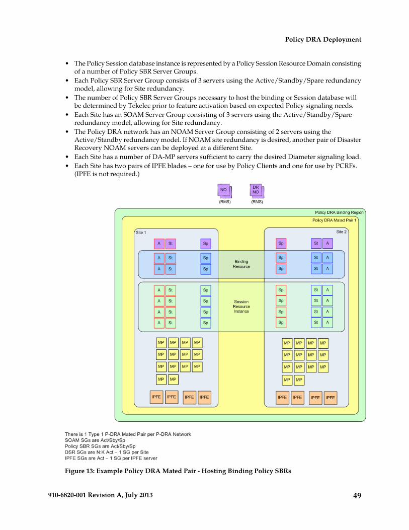
• The Policy Session database instance is represented by a Policy Session Resource Domain consistingof a number of Policy SBR Server Groups.
• Each Policy SBR Server Group consists of 3 servers using the Active/Standby/Spare redundancymodel, allowing for Site redundancy.
• The number of Policy SBR Server Groups necessary to host the binding or Session database willbe determined by Tekelec prior to feature activation based on expected Policy signaling needs.
• Each Site has an SOAM Server Group consisting of 3 servers using the Active/Standby/Spareredundancy model, allowing for Site redundancy.
• The Policy DRA network has an NOAM Server Group consisting of 2 servers using theActive/Standby redundancy model. If NOAM site redundancy is desired, another pair of DisasterRecovery NOAM servers can be deployed at a different Site.
• Each Site has a number of DA-MP servers sufficient to carry the desired Diameter signaling load.• Each Site has two pairs of IPFE blades – one for use by Policy Clients and one for use by PCRFs.
(IPFE is not required.)
Figure 13: Example Policy DRA Mated Pair - Hosting Binding Policy SBRs
49910-6820-001 Revision A, July 2013
Policy DRA Deployment

Figure 14: Example Policy DRA Mated Pair - Not Hosting Binding Policy SBRs illustrates a possibleconfiguration for additional mated pairs that do not host the Binding database:
• Each subsequent mated pair deployed after the set of mated pairs hosting the Binding databasewill host only an instance of the Session database (no Binding database).
• The number of DA-MPs can vary depending on the expected Diameter signaling load.
Figure 14: Example Policy DRA Mated Pair - Not Hosting Binding Policy SBRs
Figure 15: Policy Client, PCRF, and Site Relationships illustrates example relationships between PolicyDRA DSR Sites and Policy Clients and PCRFs:
• Each Policy DRA DSR Site has a set of Policy Clients whose primary connection is directed to thatPolicy DRA.
• Each Policy DRA DSR Site has a set of PCRFs to which it distributes new bindings. Each PCRF atthis Site has a primary connection to the Policy DRA DSR at that Site.
• Each Policy Client should have a secondary connection to the mate of the Policy DRA DSR forwhich it has a primary connection. (Without this “cross-connect”, Policy DRA site failure wouldleave the Policy Client with no access to any PCRF.)
50910-6820-001 Revision A, July 2013
Policy DRA Deployment
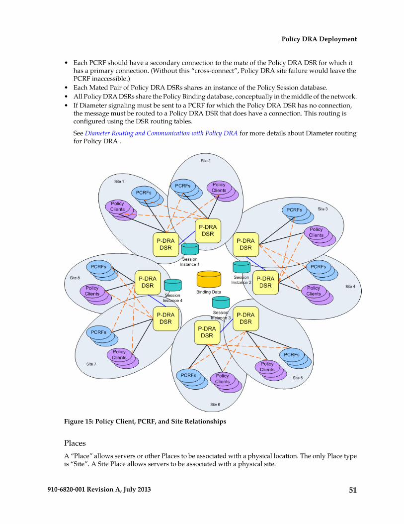
• Each PCRF should have a secondary connection to the mate of the Policy DRA DSR for which ithas a primary connection. (Without this “cross-connect”, Policy DRA site failure would leave thePCRF inaccessible.)
• Each Mated Pair of Policy DRA DSRs shares an instance of the Policy Session database.• All Policy DRA DSRs share the Policy Binding database, conceptually in the middle of the network.• If Diameter signaling must be sent to a PCRF for which the Policy DRA DSR has no connection,
the message must be routed to a Policy DRA DSR that does have a connection. This routing isconfigured using the DSR routing tables.
See Diameter Routing and Communication with Policy DRA for more details about Diameter routingfor Policy DRA .
Figure 15: Policy Client, PCRF, and Site Relationships
PlacesA “Place” allows servers or other Places to be associated with a physical location. The only Place typeis “Site”. A Site Place allows servers to be associated with a physical site.
51910-6820-001 Revision A, July 2013
Policy DRA Deployment

An OAM GUI is used to configure Sites that correspond to physical locations where equipment resides.For example, Sites may be configured for Atlanta, Charlotte, and Chicago. Exactly one Place can beassociated with a server when the server is configured
Place AssociationsA “Place Association” allows Places to be grouped in ways that make sense for DSR Applications. APlace Association is a collection of one or more Places that have a common “Type”. A Place can be amember of more than one Place Association.
The Policy DRA application defines two Place Association Types:
• Policy DRA Binding Region
As illustrated in Figure 10: Sites, Mated Pairs, and Region, the Policy DRA application defines a Regionto include all Sites that are part of the Policy DRA network. This provides a scope for the Bindingdatabase, which is accessible to all Policy DRA Sites in the Policy DRA network.
• Policy DRA Mated Pair
As illustrated in Figure 10: Sites, Mated Pairs, and Region, pairs of Policy DRA Sites are groupedtogether as Mated Pairs. Each Place Association with Type of Policy DRA Mated Pair includesexactly 2 sites. A Policy DRA Mated Pair has the following attributes:
• Hosts an instance of the Policy DRA Session database• Hosts Policy Client Diameter connections for Policy Clients at both Sites in the Mated Pair• Hosts PCRF Diameter connections for PCRFs at both Sites in the Mated Pair
Server GroupsThe Policy DRA application makes use of several different types of Server Groups, as defined in Table10: Server Group Functions.
Table 10: Server Group Functions
LevelServer Group Function NameServer Type
MPDSR (multi-active cluster)DA-MP servers
MPPolicy SBRPolicy SBR(S) and Policy SBR(B) servers
MPIP Front EndIPFE
NOAM, SOAMDSR (acative/standby pair)OAM server
• Policy SBR Type
Server Groups with the “Policy SBR” function type host either or both of the Policy Binding andPolicy Session databases. The type of Policy database hosted by a given Server Group depends onthe Resource Domain or Domains with which the Server Group is associated.
Each Policy SBR Server Group consists of one, two, or three servers, depending on the type ofdeployment. Table 11: Policy SBR Server Group Configuration and Data Redundance describes thesupported configurations for Policy SBR Server Groups. See Redundancy for details on Policy dataredundancy.
52910-6820-001 Revision A, July 2013
Policy DRA Deployment
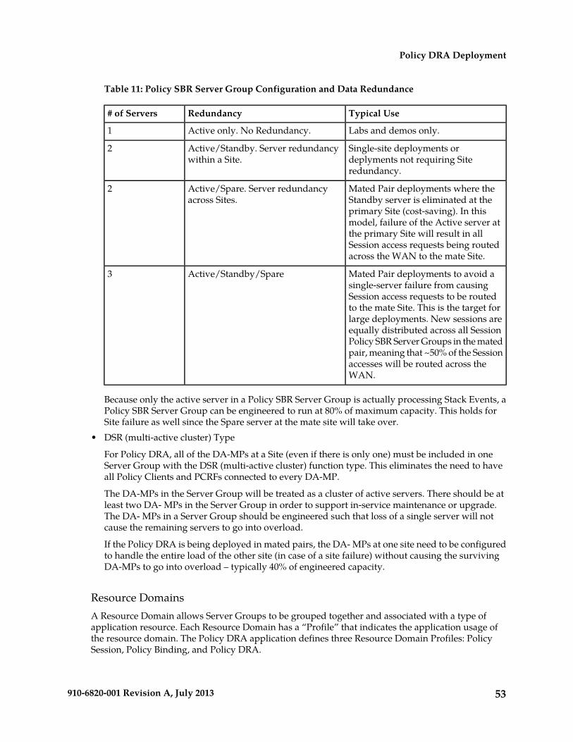
Table 11: Policy SBR Server Group Configuration and Data Redundance
Typical UseRedundancy# of Servers
Labs and demos only.Active only. No Redundancy.1
Single-site deployments ordeplyments not requiring Siteredundancy.
Active/Standby. Server redundancywithin a Site.
2
Mated Pair deployments where theStandby server is eliminated at the
Active/Spare. Server redundancyacross Sites.
2
primary Site (cost-saving). In thismodel, failure of the Active server atthe primary Site will result in allSession access requests being routedacross the WAN to the mate Site.
Mated Pair deployments to avoid asingle-server failure from causing
Active/Standby/Spare3
Session access requests to be routedto the mate Site. This is the target forlarge deployments. New sessions areequally distributed across all SessionPolicy SBR Server Groups in the matedpair, meaning that ~50% of the Sessionaccesses will be routed across theWAN.
Because only the active server in a Policy SBR Server Group is actually processing Stack Events, aPolicy SBR Server Group can be engineered to run at 80% of maximum capacity. This holds forSite failure as well since the Spare server at the mate site will take over.
• DSR (multi-active cluster) Type
For Policy DRA, all of the DA-MPs at a Site (even if there is only one) must be included in oneServer Group with the DSR (multi-active cluster) function type. This eliminates the need to haveall Policy Clients and PCRFs connected to every DA-MP.
The DA-MPs in the Server Group will be treated as a cluster of active servers. There should be atleast two DA- MPs in the Server Group in order to support in-service maintenance or upgrade.The DA- MPs in a Server Group should be engineered such that loss of a single server will notcause the remaining servers to go into overload.
If the Policy DRA is being deployed in mated pairs, the DA- MPs at one site need to be configuredto handle the entire load of the other site (in case of a site failure) without causing the survivingDA-MPs to go into overload – typically 40% of engineered capacity.
Resource DomainsA Resource Domain allows Server Groups to be grouped together and associated with a type ofapplication resource. Each Resource Domain has a “Profile” that indicates the application usage ofthe resource domain. The Policy DRA application defines three Resource Domain Profiles: PolicySession, Policy Binding, and Policy DRA.
53910-6820-001 Revision A, July 2013
Policy DRA Deployment
After Policy SBR Server Groups are configured to host the Session and Binding databases, those ServerGroups can be added to Policy Binding and Policy Session Resource Domains. A Policy SBR ServerGroup must be associated with either a Policy Session or Policy Binding Resource Domain, or withboth Policy Session and Policy Binding Resource Domains. The latter configuration is expected to beused only for small deployments.
DA- MPs are configured in a single Server Group per Policy DRA DSR with a Server Group functiontype of “DSR (multi-active cluster)”. For a mated pair deployment, the two DSR (multi-active cluster)Server Groups containing all of the DA-MPs at the two sites must be included in a Policy DRA ResourceDomain. For a non-mated deployment, the DSR (multi-active cluster) Server Group must be in its ownPolicy DRA Resource Domain.
Figure 16: Resource Domains illustrates the possible relationships between a single Policy SBR ServerGroup and the Policy Resource Domains. Although not shown in the figure, each Resource Domainwill probably contain a number of Server Groups.
54910-6820-001 Revision A, July 2013
Policy DRA Deployment
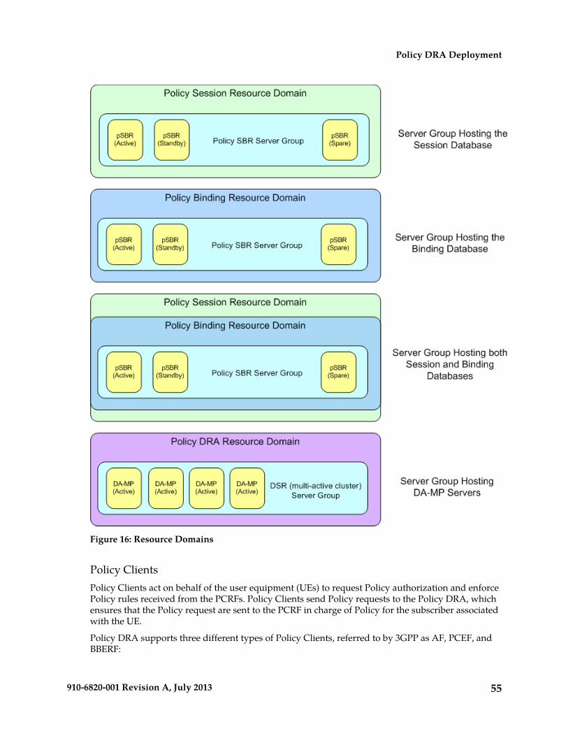
Figure 16: Resource Domains
Policy ClientsPolicy Clients act on behalf of the user equipment (UEs) to request Policy authorization and enforcePolicy rules received from the PCRFs. Policy Clients send Policy requests to the Policy DRA, whichensures that the Policy request are sent to the PCRF in charge of Policy for the subscriber associatedwith the UE.
Policy DRA supports three different types of Policy Clients, referred to by 3GPP as AF, PCEF, andBBERF:
55910-6820-001 Revision A, July 2013
Policy DRA Deployment
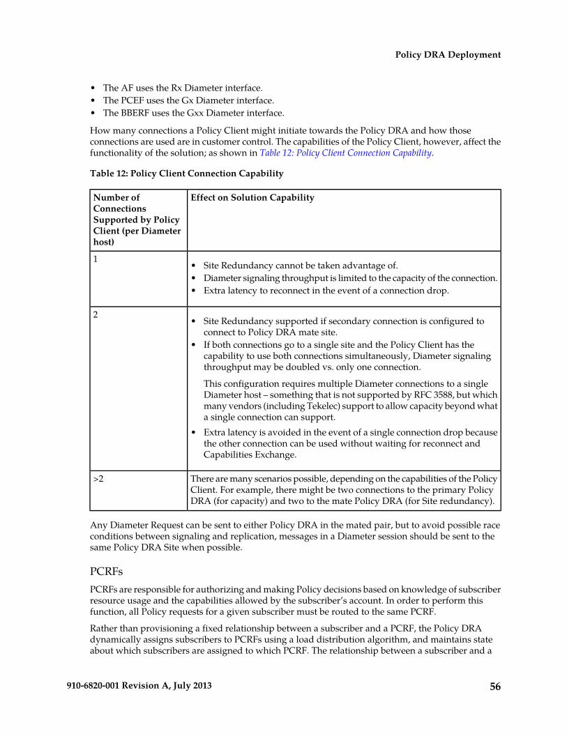
• The AF uses the Rx Diameter interface.• The PCEF uses the Gx Diameter interface.• The BBERF uses the Gxx Diameter interface.
How many connections a Policy Client might initiate towards the Policy DRA and how thoseconnections are used are in customer control. The capabilities of the Policy Client, however, affect thefunctionality of the solution; as shown in Table 12: Policy Client Connection Capability.
Table 12: Policy Client Connection Capability
Effect on Solution CapabilityNumber ofConnectionsSupported by PolicyClient (per Diameterhost)
1• Site Redundancy cannot be taken advantage of.• Diameter signaling throughput is limited to the capacity of the connection.• Extra latency to reconnect in the event of a connection drop.
2• Site Redundancy supported if secondary connection is configured to
connect to Policy DRA mate site.• If both connections go to a single site and the Policy Client has the
capability to use both connections simultaneously, Diameter signalingthroughput may be doubled vs. only one connection.
This configuration requires multiple Diameter connections to a singleDiameter host – something that is not supported by RFC 3588, but whichmany vendors (including Tekelec) support to allow capacity beyond whata single connection can support.
• Extra latency is avoided in the event of a single connection drop becausethe other connection can be used without waiting for reconnect andCapabilities Exchange.
There are many scenarios possible, depending on the capabilities of the PolicyClient. For example, there might be two connections to the primary PolicyDRA (for capacity) and two to the mate Policy DRA (for Site redundancy).
>2
Any Diameter Request can be sent to either Policy DRA in the mated pair, but to avoid possible raceconditions between signaling and replication, messages in a Diameter session should be sent to thesame Policy DRA Site when possible.
PCRFsPCRFs are responsible for authorizing and making Policy decisions based on knowledge of subscriberresource usage and the capabilities allowed by the subscriber’s account. In order to perform thisfunction, all Policy requests for a given subscriber must be routed to the same PCRF.
Rather than provisioning a fixed relationship between a subscriber and a PCRF, the Policy DRAdynamically assigns subscribers to PCRFs using a load distribution algorithm, and maintains stateabout which subscribers are assigned to which PCRF. The relationship between a subscriber and a
56910-6820-001 Revision A, July 2013
Policy DRA Deployment

PCRF can change any time the subscriber transitions from having no Diameter Policy sessions tohaving one or more Diameter Policy sessions. After a Policy session exists, however, all Policy sessionsfor that subscriber are routed to the assigned PCRF.
Policy DRA can interact with any 3GPP Release 9 compliant PCRF. Because these PCRFs come fromdifferent vendors, there are differences in how they are deployed in the network and how they “look”to the Policy DRA. The following PCRF configurations differ mainly in addressing and sharing ofstate across Diameter connections:
• A PCRF that shares state across different Diameter hostnames.
• Each Diameter hostname can all support Gx, Gxx, S9, and Rx Diameter interfaces. This type ofPCRF is supported by Policy DRA.
• Each hostname has a different connection for each different interface type. This type of PCRFis supported by Policy DRA.
• There is a different Diameter hostname for each connection for a specific Diameter interface.All of the Diameter hostnames share state. This type of PCRF is supported by Policy DRA.
• There are different Diameter hostnames for different Policy Client vendors. Policy state is sharedacross the Diameter hostnames, but origin based routing is required to select a set of PCRFs fordistribution of the initial binding depending on the Policy Client type. This type of PCRF issupported by Policy DRA, but requires use of Diameter Routing Function PCRF selection asdescribed in PCRF Selection for New Bindings.
• There is a different Diameter hostname for each connection. This type of PCRF is supported byPolicy DRA, but requires use of Diameter Routing Function PCRF selection based on the vendortype of the Policy Client as described in PCRF Selection for New Bindings.
• A PCRF that has one Diameter hostname, but supports a number of connections to that hostnameusing different IP addresses.
Each connection can support Gx, Gxx, S9, and Rx Diameter interfaces. This type of PCRF is supportedby Policy DRA.
IPFE
In order to simplify network connectivity, Policy DRA will typically be deployed with one or twopairs of IPFEs per Policy DRA DSR site. IPFE is not mandatory, however; it is up to the customerwhether it should be included.
The following deployment scenarios involving IPFE are possible:
• A single site Policy DRA in which the PCRFs are not capable of initiating connections to the PolicyDRA. For example:
• A Policy DRA DSR Site with a pair of IPFE blades, 8 DA-MP blades, and some Policy SBR blades• Four Policy Clients connected to two IPFE TSAs, with primary connections and secondary
connections• The DA-MP blades are split into two groups that host connections to TSA1 and TSA2 respectively.
This is necessary to ensure that a Policy Client’s primary and secondary connections do not endup being connected to the same DA-MP.
• One IPFE blade is primary for TSA1 and standby for TSA2; the other IPFE blade is primary forTSA2 and standby for TSA1.
• Policy DRA MPs-to-PCRFs connectivity need not be fully meshed.
57910-6820-001 Revision A, July 2013
Policy DRA Deployment

• An IPFE configuration in which Policy Clients are connected to a Policy DRA mated pair, butPCRFs are not capable of initiating connections to the Policy DRA. Each Policy Client has a primaryconnection to one Policy DRA site and a secondary connection to the mate site. For example:
• Two Policy DRA DSR sites, each with a pair of IPFE blades and 4 DA-MP blades• Three Policy Clients with a primary connection to Policy DRA DSR Site 1 and secondary
connections to Policy DRA DSR Site 2.• Three Policy Clients with a primary connection to Policy DRA DSR Site 2 and secondary
connections to Policy DRA DSR Site 1.• Two PCRFs with primary connections to Policy DRA DSR Site1 and secondary connections to
Policy DRA DSR Site 2.• Two PCRFs with primary connections to Policy DRA DSR Site2 and secondary connections to
Policy DRA DSR Site 1.• One IPFE at Policy DRA DSR Site 1 is primary for TSA1. The other IPFE is standby for TSA1.• One IPFE at Policy DRA DSR Site 2 is primary for TSA2. The other IPFE is standby for TSA2.
• A single site Policy DRA in which a single IPFE pair is used for both Policy Clients and PCRFs.The use of IPFE for PCRFs is possible only if the PCRF can be configured to initiate connectionstowards the Policy DRA. Some customers refer to an IPFE used by PCRFs as an IP Back-End, orIPBE, although there is no difference between an IPBE and an IPFE from a software or configurationperspective. For example:
• One pair of IPFE blades, each blade supporting two TSAs• Four Policy Clients connect to TSA1 with their secondary connection going to TSA3, or vice-versa.• The PCRFs connect to TSA2 with their secondary connection going to TSA4, or vice-versa.• Six Policy DRA MP servers, each capable of hosting connections from Policy Clients and PCRFs• One IPFE blade is primary for TSA1 and TSA2, and standby for TSA3 and TSA4.• The other IPFE blade is primary for TSA3 and TSA4, and standby for TSA1 and TSA2.
• A single site Policy DRA in which IPFE is used for both Policy Clients and PCRFs. In this case, twopairs of IPFE blades are deployed in order to support high Diameter signaling bandwidth. Forexample:
• Two pairs of IPFEs, each supporting a two TSAs• The Policy Clients connect to either TSA1 or TSA2, with their secondary connection going to
the other TSA.• The PCRFs connect to either TSA3 or TSA4, with their secondary connection going to the other
TSA.• Eight Policy DRA DA-MPs, each capable of hosting connections from Policy Clients and PCRFs• One IPFE blade on the Policy Client side is primary for TSA1 and standby for TSA2. The other
IPFE blade is primary for TSA2 and standby for TSA1.• One IPFE blade on the PCRF side is primary for TSA3 and standby for TSA4. The other IPFE
blade is primary for TSA4 and standby for TSA3.
• A Policy DRA mated pair configured with an IPFE for Policy Clients and a separate IPFE for PCRFs.The Policy Clients and PCRFs have a primary connection to their local Policy DRA DSR and asecondary connection to the mate Policy DRA DSR. For example:
• Two Policy DRA DSR sites, each with a two pairs of IPFE blades and 6 DA-MP blades• Three Policy Clients with a primary connection to Policy DRA DSR Site 1 and secondary
connections to Policy DRA DSR Site 2.
58910-6820-001 Revision A, July 2013
Policy DRA Deployment

• Three Policy Clients with a primary connection to Policy DRA DSR Site 2 and secondaryconnections to Policy DRA DSR Site 1.
• Two PCRFs with primary connections to Policy DRA DSR Site1 and secondary connections toPolicy DRA DSR Site 2.
• Two PCRFs with primary connections to Policy DRA DSR Site2 and secondary connections toPolicy DRA DSR Site 1.
• One IPFE on the Policy Client side at Policy DRA DSR Site 1 is primary for TSA1. The otherIPFE is standby for TSA1.
• One IPFE on the Policy Client side at Policy DRA DSR Site 2 is primary for TSA3. The otherIPFE is standby for TSA3.
• One IPFE on the PCRF side at Policy DRA DSR Site 1 is primary for TSA2. The other IPFE isstandby for TSA2.
• One IPFE on the PCRF side at Policy DRA DSR Site 2 is primary for TSA4. The other IPFE isstandby for TSA4.
Redundancy
Making the Policy DRA feature highly available is accomplished by deploying enough hardware toeliminate single points of failure. Except for lab and trial deployments, OAM servers and MP serversmust be deployed such that a single failure or maintenance activity will not prevent the feature fromperforming its function.
The Policy DRA feature also supports site redundancy, which is the ability for the feature to continuefunctioning even when an entire site is lost to disaster or network isolation.
MP Server Redundancy
The following redundancy models are supported for MP servers, whether deployed as DA-MPs orPolicy SBR MPs:
• DA-MP Multi-Active Cluster
Policy DRA DA-MPs are deployed using an Active/Active redundancy model. This means thatevery DA-MP actively processes Diameter signaling. In order to avoid single points of failure, aminimum of two DA-MPs must be deployed (except for lab and trial deployments, where oneDA-MP is acceptable). DA-MPs at a given site must be configured such that loss of a single DA-MPwill not cause the remaining DA-MP servers to go into signaling overload.
• Policy SBR Active Only
A Policy SBR (either Session or Binding) can be deployed in simplex redundancy mode only forlabs or trials. Otherwise this configuration represents a single point of failure for the Policy SBRdatabase being hosted by the Active-only Server Group. In this configuration, the Policy SBR ServerGroups consist of a single Server.
• Policy SBR Active/Standby
The Active/Standby redundancy model should be used for single site Policy DRA deployments,or for multi-site deployments when site redundancy is not important. In this configuration, thePolicy SBR Server Groups consist of two servers. On system initialization, one of the two serversin each Policy SBR Server Group will be assigned the Active role and the other the Standby role.
59910-6820-001 Revision A, July 2013
Policy DRA Deployment

These roles will not change unless a failure or maintenance action causes a switch-over. ForActive/Standby Server Groups, switch-overs are non-revertive, meaning that recovery of a formerlyActive server will not cause a second switch-over to revert the Active role to that server.
• Policy SBR Active/Spare
The Active/Spare redundancy model can be used for mated pair deployments in which it isacceptable for traffic to move from one site to the mate site on failure of a single server. In thisconfiguration, the Policy SBR Server Groups consist of two servers with one marked as “PreferredSpare”. On system initialization, the server not marked as Preferred Spare will be assigned theActive role and the other the Spare role. These roles will not change unless a failure or maintenanceaction causes a switch-over. For Active/Spare Server Groups, switch-overs are revertive, meaningthat recovery of a formerly Active server will cause a second switch-over to revert the Active roleto that server.
• Policy SBR Active/Standby/Spare
The Active/Standby/Spare redundancy model should be used for Policy DRA mated pairdeployments in which site redundancy is desired. In this configuration, each Policy SBR ServerGroup is configured with two servers at one site and the third at the mate site. The server at themate site is designated in the Server Group configuration as “Preferred Spare”. On systeminitialization, one of the two servers that are located at the same site will be assigned the Activerole and the other the Standby role. The server at the mate site will be assigned the Spare role (aswas preferred). If the Active server can no longer perform its function due to failure or maintenance,the Standby Server will be promoted to Active. Only if both Active and Standby servers at a siteare unable to perform their function will the Spare server at the mate site be promoted to Active.Active and Standby role changes within a site are non-revertive, but if the server at the mate siteis Active and one of the other servers recovers, a switch-over will occur to revert the Active roleback to the site with two servers.
Site Redundancy
Site redundancy is the ability to lose an entire site, for example due to a natural disaster or majornetwork failure, without losing signaling or application state data. For Policy DRA this means no lossof Policy Binding or Policy Session data. In order to achieve site redundancy, the following configurationapplies:
• Policy DRA is deployed on at least one mated pair of Policy DRA DSRs.• Policy Clients and PCRFs are able to connect to both sites in the mated pair.• Policy SBR Server Groups are set up to use the Active/Standby/Spare or Active/Spare redundancy
model.• System OAM (SOAM) Server Groups are set up to use the Active/Standby/Spare redundancy
model.• DA-MPs are recommended to be engineered at 40% capacity across the mated pair.
Data Redundancy
The Policy Session and Policy Binding databases are partitioned such that each Server Group in aPolicy Session or Policy Binding Resource Domain hosts a portion of the data. Because each ServerGroup consists of redundant servers (Active/Standby, Active/Spare, or Active/Standby/Spare), thedata owned by each Server Group is redundant within the Server Group.
60910-6820-001 Revision A, July 2013
Policy DRA Deployment
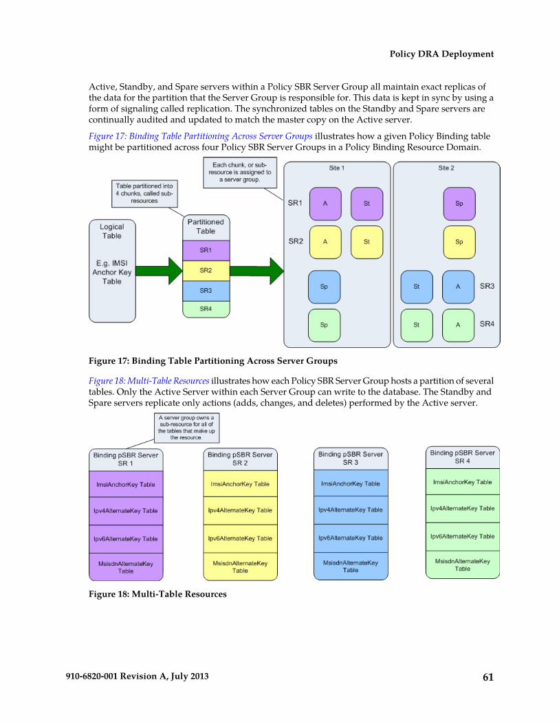
Active, Standby, and Spare servers within a Policy SBR Server Group all maintain exact replicas ofthe data for the partition that the Server Group is responsible for. This data is kept in sync by using aform of signaling called replication. The synchronized tables on the Standby and Spare servers arecontinually audited and updated to match the master copy on the Active server.
Figure 17: Binding Table Partitioning Across Server Groups illustrates how a given Policy Binding tablemight be partitioned across four Policy SBR Server Groups in a Policy Binding Resource Domain.
Figure 17: Binding Table Partitioning Across Server Groups
Figure 18: Multi-Table Resources illustrates how each Policy SBR Server Group hosts a partition of severaltables. Only the Active Server within each Server Group can write to the database. The Standby andSpare servers replicate only actions (adds, changes, and deletes) performed by the Active server.
Figure 18: Multi-Table Resources
61910-6820-001 Revision A, July 2013
Policy DRA Deployment

OAM Server Redundancy
The Policy DRA application can be deployed with varying degrees of redundancy on the NOAM andSOAM servers. Like the Policy SBR servers, the OAM servers can be configured to support siteredundancy if desired.
Regardless of whether site redundancy is supported, the OAM servers must be deployed on redundantservers at a given site.
• Active/Standby NOAM and Active/Standby DR NOAM
The NOAM servers are deployed using the active/standby redundancy model at one of the sitesin the Policy DRA network. If site redundancy is desired, an optional pair of Disaster Recovery(DR) NOAM servers can be deployed at a different site. The DR NOAM servers are used only ifmanually brought into service following loss of the site where the original NOAM pair was located.
• Active/Standby/Spare SOAM
If site redundancy is desired for Policy DRA mated pairs, the SOAM servers at each of the mateDSRs should be deployed using the Active/Standby/Spare redundancy model. In this configuration,two SOAM servers are deployed at one site and a third server is deployed at the mate site. Thethird server is configured as “Preferred Spare” in the SOAM Server Group. In the event of a sitefailure, the Policy SBR Servers running at the surviving site of the mated pair will reportmeasurements, events, and alarms to the SOAM server at that site. Without the Spare SOAM server,the Spare Policy SBR servers would have no parent OAM server and would not be able to reportmeasurements, events, and alarms.
Policy SBR servers in a given Policy SBR Server Group must be set up such that they belong to theSignaling Network Element of the site that has two of the three servers. This will allow all three serversin the Server Group to merge their measurements, events, and alarms to the same SOAM Server Group.
Figure 19: Data Merging - Normal Case illustrates how measurements, alarms, and events are merged.MP servers merge to the Active SOAM server for the signaling network element they belong to. TheActive SOAM server then replicates the data to its Standby and Spare servers.
62910-6820-001 Revision A, July 2013
Policy DRA Deployment
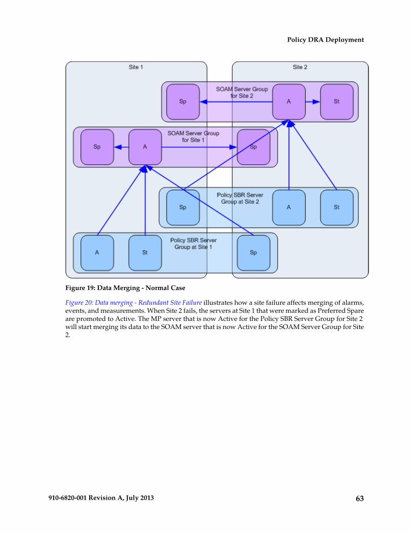
Figure 19: Data Merging - Normal Case
Figure 20: Data merging - Redundant Site Failure illustrates how a site failure affects merging of alarms,events, and measurements. When Site 2 fails, the servers at Site 1 that were marked as Preferred Spareare promoted to Active. The MP server that is now Active for the Policy SBR Server Group for Site 2will start merging its data to the SOAM server that is now Active for the SOAM Server Group for Site2.
63910-6820-001 Revision A, July 2013
Policy DRA Deployment
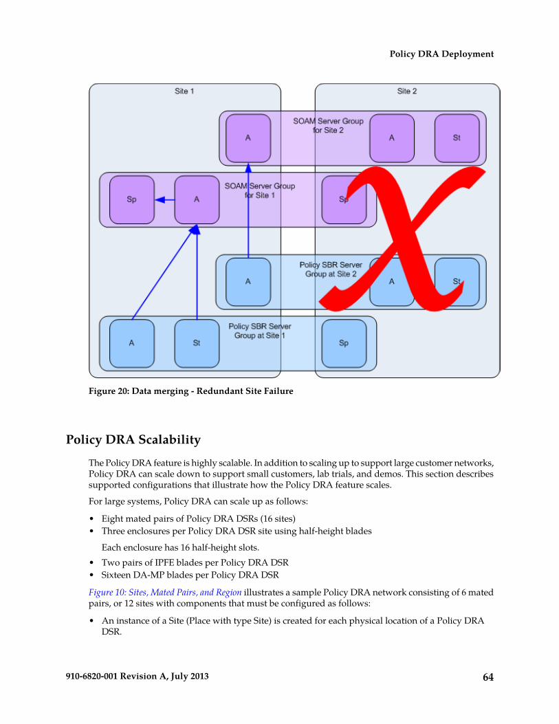
Figure 20: Data merging - Redundant Site Failure
Policy DRA Scalability
The Policy DRA feature is highly scalable. In addition to scaling up to support large customer networks,Policy DRA can scale down to support small customers, lab trials, and demos. This section describessupported configurations that illustrate how the Policy DRA feature scales.
For large systems, Policy DRA can scale up as follows:
• Eight mated pairs of Policy DRA DSRs (16 sites)• Three enclosures per Policy DRA DSR site using half-height blades
Each enclosure has 16 half-height slots.• Two pairs of IPFE blades per Policy DRA DSR• Sixteen DA-MP blades per Policy DRA DSR
Figure 10: Sites, Mated Pairs, and Region illustrates a sample Policy DRA network consisting of 6 matedpairs, or 12 sites with components that must be configured as follows:
• An instance of a Site (Place with type Site) is created for each physical location of a Policy DRADSR.
64910-6820-001 Revision A, July 2013
Policy DRA Deployment

• All MP servers (both Policy SBRs and DA-MPs) are assigned to the Site where they are physicallylocated.
• An instance of a Policy DRA Mated Pair (Place Association with type Policy DRA Mated Pair) iscreated for each pair of sites that are mates.
• A pre-determined number of Policy Binding Server Groups are created on the Policy DRA DSRnodes that are initially deployed.
• Each Policy Binding Server Group, if configured for site redundancy, must have at least oneServer at the home site and one Server at the mate site.
• Policy Binding Server Groups can exist on more than 2 sites, but the Policy DRA network is notoperational until all sites hosting Policy Binding Server Groups are operational.
• A Policy Binding Resource Domain is created including all Policy Binding Server Groups.• A pre-determined number of Policy Session Server Groups are created at each mated pair.
Each Policy Session Server Group, if configured for site redundancy, must have at least one serverat the home site and one server at the mate site.
• A Policy Session Resource Domain is created for each mated pair including the Policy SessionServer Groups at the two mated sites.
• A DSR (multi-active cluster) Server Group is created for each Site, containing all of the DA-MPservers at the Site.
• A Policy DRA Resource Domain is created including the DSR Server Group at each of the matedSites.
• A Policy DRA Binding Region (Place Association with type Policy DRA Binding Region) is createdcontaining all Sites.
The Mated Pair of Policy DRA DSR sites illustrated in Figure 5 could support approximately 336,000Diameter MPS with site redundancy (with DA-MPs engineered at 40%).
The single site Policy DRA DSR illustrated in Figure 6 could support approximately 384,000 DiameterMPS (with DA-MPs engineered at 80%).
MP Growth
The Policy DRA feature supports addition of DA-MPs as needed to support Diameter traffic. EachPolicy DRA DA-MP can support 12,000 MPS when engineered to run at 40% to support site redundancy.If site redundancy is not needed, Policy DRA DA-MPs can be engineered at 80%, thereby supporting24,000 MPS.
The DSR supports up to 16 DA-MPs per DSR site.
Database Growth
The Policy DRA feature does not support growth of the Policy Session or Policy Binding databasesafter feature activation.
Note: The percentages of different types of Policy Diameter messages in the overall Policy Diametertraffic load is referred to as the call model.
This has the following implications:
• The number of Server Groups that will host the Policy Session database for each mated pair (orsingle site if no mated pair is planned) must be determined prior to feature activation.
65910-6820-001 Revision A, July 2013
Policy DRA Deployment
The number of Policy Session Server Groups required depends on the expected Diameter trafficrate in MPS for Policy signaling and the ratio of Diameter MPS to Session stack events determinedby the call model.
• The number of Policy Binding database Server Groups for the entire planned Policy DRA networkmust be determined prior to feature activation.
The number of Policy Binding Server Groups required depends on the number of Policy subscribersand the expected Diameter traffic rate in MPS for Policy signaling and the ratio of Diameter MPSto Binding stack events determined by the call model.
• After the number of Policy Binding and Policy Session Server Groups has been configured at PolicyDRA feature activation time, these numbers cannot be changed without deactivating the feature.
Deactivation of the Policy DRA feature results in an outage for all Policy signaling that traversesall Policy DRA DSRs in the Policy DRA network.
Mated Pair Growth
A mate Policy DRA DSR can be added to a single-site Policy DRA DSR.
A mated pair of Policy DRA DSRs can be added to a Policy DRA network.
Adding a Mate Policy DRA DSR to an Existing Policy DRA DSRBecause Policy SBR growth is not supported, a Policy DRA DSR deployed without a mate must hostall of the Policy SBR Server Groups that are planned for deployment across the mated pair when themate is added. This requires planning ahead for the eventual mate.
Note: Policy SBR Server Groups with only one server represent a single point of failure for a portionof the Policy SBR database.
A Policy DRA DSR site could be configured as follows for eventually adding a mate:
• Site A has two SOAM Server Groups configured: the red one on the top left for use by Site A andthe blue one on the top right for use by Site B.
• The Site A SOAM Server Group is set up with two Servers in Active/Standby configuration.• The Site B SOAM Server Group is set up with one Server configured as Preferred Spare. Because
there are no other Servers in this Server Group, the Server will become active.
• Site A has four Policy SBR(B) Server Groups configured: the two red ones on the left for use by SiteA and the two blue ones on the right for use by Site B.
• The Site A Policy SBR(B) Server Groups are set up with two Servers in Active/Standbyconfiguration. These Server Groups have the Site A SOAM Server Group as parent.
• The Site B Policy SBR(B) Server Groups are set up with one Server configured as PreferredSpare. These Server Groups have the Site B SOAM Server Group as parent. Because there areno other Servers in these Server Groups, the single Server will become active.
• Site A has eight Policy SBR(S) Server Groups configured: the four red ones on the left for use bySite A and the four blue ones on the right for use by Site B.
• The Site A Policy SBR(S) Server Groups are set up with two servers in Active/Standbyconfiguration. These Server Groups have the Site A SOAM Server Group as parent.
66910-6820-001 Revision A, July 2013
Policy DRA Deployment

• The Site B Policy SBR(S) Server Groups are set up with one Server configured as Preferred Spare.These Server Groups have the Site B SOAM Server Group as parent. Because there are no otherServers in these Server Groups, the single Server will become active.
Adding a Mated Pair of Policy DRA DSRsPolicy DRA network capacity can be expanded by adding mated pairs of Policy DRA DSRs. PolicyDRA mated pairs added after the Policy DRA network is up and running cannot include additionalPolicy Binding Policy SBR Servers.
The number of Policy Session Policy SBR Servers must be the same for each of the new Policy DRAmates, and must be determined at Policy DRA feature activation. Every Policy DRA mated pair musthave the same number of Policy Session Policy SBR Server Groups. After the number is selected thevalue cannot change until a software upgrade becomes available that supports Policy SBR growth.
While Policy SBR growth (adding Policy SBR Server Groups) is not supported, Policy DRA MP serverscan be added as needed (up to a maximum of 16 DA-MPs) to support the desired level of Diametersignaling traffic.
Small System Support
In order to support small customers and lab and trial deployments, the Policy DRA feature can scaledown to run on a small hardware footprint. This section describes the smallest supported Policy DRADSR deployments.
A lab or trial system may not be required to support in-service maintenance, or have any hardwareredundancy whatsoever. In the smallest supported lab/trial Policy DRA DSR, IPFE is not includedbecause it does not make sense to distribute ingress connections when there is only one DA-MP server.
The NOAM and SOAM servers are also running in simplex mode, meaning that no redundancy exists.In addition, the NOAM and SOAM are virtualized on a single physical server to save hardware. ThePolicy SBR Server is also running in simplex mode and is configured to host both the Policy Bindingand Policy Session databases. A single DA-MP hosts all Diameter signaling. Signaling is not affectedif one or both of the (virtual) OAM servers happens to fail.
The configuration of the smallest viable commercially deployable Policy DRA DSR has enoughhardware redundancy to support in-service maintenance:
• Two DA-MPs are required to survive server failures and maintenance. These DA-MPs should beengineered at 40% load since in a failure or maintenance situation, one Server will have to handlethe load for both.
• The Policy SBR Server pair uses the Active/Standby redundancy model in order to support failuresand maintenance.
• The Policy SBR Server pair hosts both the Policy Binding and Policy Session databases.• The NOAM/SOAM Server pair uses the Active/Standby redundancy model in order to support
failures and maintenance.• Both NOAM and SOAM are virtualized onto a single pair of physical servers. The NOAM instance
is Active on one server and Standby on the other. The SOAM instance is Active on one server andStandby on the other.
The smallest supported Mated Pair of Policy DRA DSRs, illustrated in Figure 21: Smallest SupportedPolicy DRA Mated Pair, has the following characteristics:
• The NOAM servers are deployed at Site 1 using Active/Standby redundancy.
67910-6820-001 Revision A, July 2013
Policy DRA Deployment
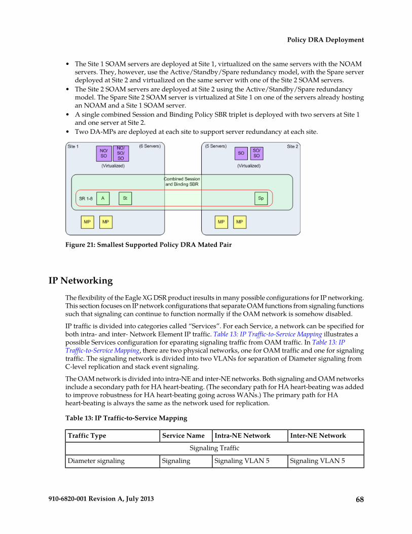
• The Site 1 SOAM servers are deployed at Site 1, virtualized on the same servers with the NOAMservers. They, however, use the Active/Standby/Spare redundancy model, with the Spare serverdeployed at Site 2 and virtualized on the same server with one of the Site 2 SOAM servers.
• The Site 2 SOAM servers are deployed at Site 2 using the Active/Standby/Spare redundancymodel. The Spare Site 2 SOAM server is virtualized at Site 1 on one of the servers already hostingan NOAM and a Site 1 SOAM server.
• A single combined Session and Binding Policy SBR triplet is deployed with two servers at Site 1and one server at Site 2.
• Two DA-MPs are deployed at each site to support server redundancy at each site.
Figure 21: Smallest Supported Policy DRA Mated Pair
IP Networking
The flexibility of the Eagle XG DSR product iresults in many possible configurations for IP networking.This section focuses on IP network configurations that separate OAM functions from signaling functionssuch that signaling can continue to function normally if the OAM network is somehow disabled.
IP traffic is divided into categories called “Services”. For each Service, a network can be specified forboth intra- and inter- Network Element IP traffic. Table 13: IP Traffic-to-Service Mapping illustrates apossible Services configuration for eparating signaling traffic from OAM traffic. In Table 13: IPTraffic-to-Service Mapping, there are two physical networks, one for OAM traffic and one for signalingtraffic. The signaling network is divided into two VLANs for separation of Diameter signaling fromC-level replication and stack event signaling.
The OAM network is divided into intra-NE and inter-NE networks. Both signaling and OAM networksinclude a secondary path for HA heart-beating. (The secondary path for HA heart-beating was addedto improve robustness for HA heart-beating going across WANs.) The primary path for HAheart-beating is always the same as the network used for replication.
Table 13: IP Traffic-to-Service Mapping
Inter-NE NetworkIntra-NE NetworkService NameTraffic Type
Signaling Traffic
Signaling VLAN 5Signaling VLAN 5SignalingDiameter signaling
68910-6820-001 Revision A, July 2013
Policy DRA Deployment

Inter-NE NetworkIntra-NE NetworkService NameTraffic Type
Signaling VLAN 4Signaling VLAN 4ComAgentStack events sent betweenDA-MPs, between DA-MPsand Policy SBRs, and betweenPolicy SBRs
Signaling VLAN 4Signaling VLAN 4Replication_MPReplication of data amongDA-MPs
Signaling VLAN 4Signaling VLAN 4Replication_MPReplication of data amongPolicy SBRs
Signaling VLAN 4Signaling VLAN 4Replication_MPHA Heartbeating among PolicySBRs (Primary Path)
Signaling VLAN 4Signaling VLAN 4Replication_MPHA Heartbeating amongDA-MPs (Primary Path)
OAM VLAN 3OAM VLAN 3HA_MP_SecondaryHA Heartbeating among PolicySBRs (Secondary Path)
OAM VLAN 3OAM VLAN 3HA_MP_SecondaryHA Heartbeating amongDA-MPs (Secondary Path)
OAM Traffic
OAM VLAN 3IMIReplicationReplication of configurationdata from NOAMs to SOAMsand from SOAMs to MPs
OAM VLAN 3IMIReplicationMerging of measurements,events, and alarms from MPsto SOAMs and from SOAMsto NOAMs
OAM VLAN 3IMIReplicationSNMP traps
OAM VLAN 3IMIOAMSOAP Signaling
IMIOAMFile Transfers to/from the FileManagement Area
OAM VLAN 3IMIReplicationHA Heartbeating among OAMservers (Primary Path)
Signaling VLAN 4Signaling VLAN 4HA_SecondaryHA Heartbeating among OAMservers (Secondary Path)
69910-6820-001 Revision A, July 2013
Policy DRA Deployment

Chapter
4Policy DRA Configuration
The Policy DRA > Configuration GUI pages forPolicy DRA components provide fields for entering
Topics:
• Policy DRA Configuration Overview.....71 the information needed to manage Policy DRAconfiguration in the DSR.• Pre-Configuration Activities.....73
• Policy DRA Configuration on the NOAM and theSOAM.....78
• Post-Configuration Activities.....106• DSR Bulk Export.....107• DSR Bulk Import.....109
70910-6820-001 Revision A, July 2013

Policy DRA Configuration Overview
The Policy DRA > Configuration GUI pages for Policy DRA components provide fields for enteringthe information needed to manage Policy DRA configuration in the DSR.
The Policy DRA application must be activated in the system before Policy DRA configuration can beperformed.
The DSR 3-tiered Operations, Administration, and Maintenance (OAM) topology is required for thePolicy DRA application. 3-tiered OAM topology consists of the following tiers:
• A pair of NOAM servers running in active/standby redundancy
OAM configuration is performed on the NOAM.
As shown in Figure 22: GUI Structure for 3-tiered DSR Topology with Policy DRA, network-wide PolicyDRA configuration is performed on the NOAM.
• A pair or triplet of SOAM servers at each site running in active/standby, or active/standby/spareredundancy
Diameter protocol configuration is done on the SOAM.
Most of the OAM configuration components are viewable on the SOAM.
Most DSR Application configuration is done on the SOAM.
As shown in Figure 22: GUI Structure for 3-tiered DSR Topology with Policy DRA, site-specificconfiguration for Policy DRA is performed on the SOAM; some network-wide Policy DRAconfiguration components are viewable on the SOAM.
• A set of MP servers, which can host signaling protocol stacks (for example, DA-MPs), or in-memorydatabase servers (for example, Policy Session Binding Repository [SBR])
An optional pair of Disaster Recovery NOAMs can be configured to manually take over in the eventof loss of both the active and standby NOAMs
The three tiers allow configured data to be replicated down to the MP servers, and measurements,events, and alarms to be merged up to the OAM servers.
3-tiered topology allows administrators to access all DSR GUI pages from a single sign-on. Anadministrator can access the DSR SOAM when logged into the DSR NOAM, without needing tore-enter login credentials.
71910-6820-001 Revision A, July 2013
Policy DRA Configuration

Figure 22: GUI Structure for 3-tiered DSR Topology with Policy DRA
NOAM and SOAM Configuration
Configuration data is divided into two categories depending on the scope of the data:
• Network-wide data is configured at the NOAM and is called A-scope data.• Per-site data is configured at the SOAM for a given site and is called B-scope data.
In general, topology data like creation of sites, assignment of servers to sites, creation of server groups,and so on is A-scope data. DSR data configuration is generally site-scoped, or B-scope data.
72910-6820-001 Revision A, July 2013
Policy DRA Configuration

Some Policy DRA data must be configured at the A-scope level and some data must be configured atthe B-scope level.
Policy related data configured at the NOAM include:
• Assignment of Servers to Site Places• Assignment of Servers to Policy SBR Server Groups• Assignment of Policy SBR Server Groups to Policy Session and/or Policy Binding Resource Domains• Assignment of DSR Multi-active Cluster Server Groups to Policy DRA Resource Domains• Assignment of Site Places to Policy DRA Mated Sites Place Associations• Assignment of Site Places to Policy DRA Binding Region Place Associations
Policy DRA-specific data configured at the NOAM include:
• Alarm Thresholds for:
• Policy DRA Application Ingress Message Rate• Policy Session Database Capacity• Policy Binding Database Capacity
• Access Point Names (APN)• Maximum Session Inactivity Time per APN
Policy DRA-specific data configured at the SOAM include:
• PCRFs local to the site• Binding Key Priority for the site• Topology Hiding configuration for the site• Error response configuration for the site
Pre-Configuration Activities
Before Policy DRA configuration can be performed, the following activities need to be performed inthe system:
• Verify that the Policy DRA application is activated in the system. (This is usually performed aspart of the installation or upgrade activities.)
Policy DRA appears in the left-hand GUI menu on the NOAM and the SOAM after the applicationis activated.
• Verify that the following NOAM configuration is complete for Policy DRA:
• Places
Select Configuration ➤ Places.
Click Report to generate a report about the configured Places.
Click Print to print the report, or Save to save the report as a text file.• Place Associations
Select Configuration ➤ Place Associations.
Click Report to generate a report about the configured Place Associations
73910-6820-001 Revision A, July 2013
Policy DRA Configuration
Click Print to print the report, or Save to save the report as a text file.• Resource Domains
Select Configuration ➤ Resource Domains.
Click Report to generate a report about the configured Resource Domains
Click Print to print the report, or Save to save the report as a text file.
Note: A Resource Domain cannot be deleted that is part of a Policy Binding or Policy Sessionprofile, unless the P-DRA feature is deactivated. Resource Domains that are part of Policy DRAprofiles can be deleted when the Policy DRA application is activated.
• Gather component information that is required for Diameter and Policy DRA configuration,including component item naming conventions and names, IP addresses, hostnames, and numbersof items to be configured.
Naming Conventions and Hierarchical Routing illustrates the use of a naming convention.• Configure Diameter Configuration components that are required for Policy DRA configuration.
See Diameter Configuration for Policy DRA.
Diameter Configuration for Policy DRA
The Policy DRA application requires configuration of several Diameter Configuration componentsbefore the Policy DRA configuration can be performed.
All Diameter Configuration components are configured using the SOAM GUI.
Use the explanations and procedures in the Diameter Configuration online help and the Diameter andMediation User Guide to complete the configuration of the Diameter Configuration components for thesystem, including the following Diameter Configuration components for use with the Policy DRAapplication.
1. MP Profiles
Select Diameter ➤ DA-MPs ➤ Profile Assignments, and verify that the correct Session MP Profileshave been assigned for Policy DRA DA-MPs. If assignments need to be made or changed,
• Use the Diameter > Configuration > DA-MPs > Profile Assignments page to assign an MPProfile for each configured Policy DRA DA-MP shown in the DA-MP list.
• From the pulldown list, select the MP Profile that is for the correct blade type and for a Sessionapplication (such as G6 Session or G8 Session).
2. Application Ids
Use the Diameter > Configuration > Application Ids [Insert] page to define an Application Id foreach Diameter interface that will be used by Policy DRA in the system.
Policy DRA supports the following values that can be selected in the Application Id Value pulldownlist:
• 16777236 – 3GPP Rx• 16777238 – 3GPP Gx• 16777266 – 3GPP Gxx• 16777267 – 3GPP S9• 4294967295 – Relay
74910-6820-001 Revision A, July 2013
Policy DRA Configuration

Policy DRA always attempts to route using Peer Route Tables. The Peer Route Table can beconfigured here for each Application Id, or can be configured for Peer Nodes. If neither is configured,the Default Peer Route Table will be used. See Policy DRA Routing of Diameter Messages.
3. CEX Parameters
Use the Diameter > Configuration > CEX Parameters [Insert] page to define the Capability Exchangeparameters for each Application Id that was configured for use by Policy DRA:
For each Application Id, select or enter:
• Application Id Type – Authentication• Vendor Specific Application Id, if the Application Id and Vendor Id will be grouped in a
Vendor-specific Application Id AVP• Vendor Id – if Vendor Specific Application Id is selected
The Vendor ID 10415 is defined in 3GPP as follows:
• Gx: 16777238 with Vendor-Id of 10415 (Defined in 3GPP 29.212)• Gxx: 16777266 with Vendor-Id of 10415 (Defined in 3GPP 29.212)• Rx: 16777236 with Vendor-Id of 10415 (Defined in 3GPP 29.214)• S9: 16777267 with Vendor-Id of 10415 (Defined in 3GPP 29.215)
4. CEX Configuration Sets
Use the Diameter > Configuration > Configuration Sets > CEX Configuration Sets [Insert] pageto select the configured CEX parameters to use in:
• A CEX Configuration Set to be used for connections with the PCEF nodes (Gx)• A CEX Configuration Set to be used for connections with the AF nodes (Rx)• A CEX Configuration Set to be used connections with the PCRF nodes (Gx and Rx)• CEX Configuration Sets to be used with any other types of nodes, such as BBERF (Gxx)• A CEX Configuration Set named Default is provided for the Relay Application Id; it can be
edited if needed.
5. Local Nodes (Policy DRA DA-MPs)
Use the Diameter > Configuration > Local Nodes [Insert] page to configure the Policy DRADA-MPs as Local Nodes in the system.
The pulldown list of IP Addresses contains the XSI addresses configured on DSR MP Servers.6. Peer Nodes
Use the Diameter > Configuration > Peer Nodes [Insert] page to configure PCEFs, AFs, BBERFs,and any other types of nodes as Peer Nodes to the Policy DRA DA-MPs in the system. (Policy DRADA-MPS can also be Peer Nodes to each other at different sites.)
See Policy DRA Routing of Diameter Messages for details on routing of messages for Policy DRA.7. Connections
Use the Diameter > Configuration > Peer Nodes [Insert] page to configure connections betweenthe Policy DRA DA-MPS and the Peer Nodes.
Any IPFE Target Set Address (TSA) that is used to configure a connection must use the sameTransport Protocol (SCTP or TCP) that is selected to configure the connection.
8. Route Groups
75910-6820-001 Revision A, July 2013
Policy DRA Configuration

Use the Diameter > Configuration > Route Groups [Insert] page to configure Route Groups foruse with Policy DRA Peers.
For priority-based initial CCR-I routing, configure N+1 Route Groups where N is the number ofPCRFs in the system. The first N Route Groups contain one corresponding PCRF Peer Node ineach one, and the last Route Group contains all PCRFs.
The goal is to setup a routing configuration such that if there is no route available to the suggestedPCRF in an initial (binding capable) session Request, Diameter automatically sends the Requestmessages to any other available PCRF.
Define a Route Group for each PCRF; enter the Route Group Name, select the Peer Node name(PCRF name) and enter the Provisioned Capacity as 1.
Define a last Route Group for all PCRFs; enter the Route Group Name, then add a Peer Node,Connection and Capacity entry for every PCRF. Select the Peer Node (PCRF) and enter theProvisioned Capacity as 1 for each PCRF entry.
9. Route Lists
Use the Diameter > Configuration > Route Lists [Insert] page to configure Route Lists for usewith the configured Route Groups.
For priority-based initial session binding, configure N Route Lists where N is the number of PCRFsin the system.
All Route Lists must contain at least two Route Groups, one for a single PCRF and one for all PCRFs.
Assign Priority value 1 to each Route Group for a single PCRF; assign Priority value 2 to the RouteGroup containing all the PCRFs.
Enter 1 for the Minimum Route Group Availability Weight in all of the Route Lists.10. Peer Route Table and Peer Routing Rules
Use the Diameter > Configuration > Peer Route Tables [Insert] page to configure new Peer RouteTables if needed, and the Viewing Rules for Peer Route Table page to configure Peer RoutingRules, such that DSR forwards messages based on the PCRF preference.
Peer Routing Rules can be added to the Default Peer Route Table (PRT) or to new Peer Route Tables.
See Policy DRA Routing of Diameter Messages for details on PRT routing of Policy DRA messages.
The routing configuration will ensure that whenever Policy DRA requests Diameter to route to aparticular PCRF based on the PRT:
• If the PCRF is available, Diameter will route to it.• If the PCRF is not available, Diameter will route the message to any other available PCRF.
11. Application Routing Rules
Use the Diameter > Configuration > Application Routing Rules page to configure an ApplicationRouting Rule for each Diameter interface (such as Gx or Rx) that is configured in an ApplicationId, to be used for Diameter routing of messages to the Policy DRA application. Policy DRA mustreceive all Policy Diameter Requests.
For each rule, enter or select:
• Rule Name for a configured Application Id (Diameter interface)• Priority
76910-6820-001 Revision A, July 2013
Policy DRA Configuration

• In Conditions, for Application Id select from the pulldown lists the Equals Operator and theApplication Id configured for Policy DRA.
• Application Name - PDRA
Policy DRA Routing of Diameter MessagesPolicy DRA routes Diameter messages depending on the following criteria:
• Answer message or Request message• New session Request or in-session Request• New binding or existing binding new session Request
Peer Routing
Policy DRA always attempts to route using Peer Route Tables. The Diameter Routing Function attemptsto use Peer Route Tables in the following predefined precedence:
1. Peer Route Table configured for the originating Peer Node (Diameter->Configuration->Peer Nodes)
If a match is found, the specified Peer Route Table is used.2. Peer Route Table configured for the Diameter Application-ID of the policy session initiation request
being routed (Diameter->Configuration->Application Ids)
If the ingress Peer Node is configured as "Not Selected", that entry is skipped and the ApplicationIds configuration is checked.
3. Default Peer Route Table
If no match is found in the Application-Ids configuration, the Default Peer Route Table is used.4. Destination-Host Routing
If no Peer Routing Rule matches in the Default Peer Route Table, Policy DRA will attempt to routethe Request using Destination-Host routing (for example, to a connection or Alternate ImplicitRoute List associated with the destination Peer Node).
Routing of Session Initiation Requests for New Bindings
Policy DRA allows a Peer Route Table to be configured for use when a new binding is created. ThisPeer Route Table can specify Peer Routing Rules to:
• Allow new bindings to be routed, for example, based on the Origin-Host or Origin-Realm of thePCEF
• Cause new bindings to be load-shared across all local PCRFs.
The Peer Route Table to use for new bindings is specified in the Policy DRA->Configuration->SiteOptions GUI page on the SOAM at each site.
If the Peer Route Table for new bindings is set to "Not Selected", the Diameter Routing Function usesthe precedence described in Peer Routing.
Routing of Session Initiation Requests for Existing Bindings
Sessions for subscribers that are already bound to a PCRF must be routed to the bound PCRF, or to aPCRF that shares state with the bound PCRF if the PCRF supports sharing of policy state. For existing
77910-6820-001 Revision A, July 2013
Policy DRA Configuration

bindings, no Peer Route Table is configured in the Policy DRA application Site Options. Instead, theDiameter Routing Function uses the precedence described in Peer Routing.
Routing of Requests from PCRF to a Policy Client
In order to route Requests initiated by the PCRF, routing must be configured such that Requests fromany PCRF can be routed to any Policy Client in the network. This type of routing is used to route RARand ASR requests. For Requests from PCRFs to Policy Clients, no Peer Route Table is configured inthe Policy DRA application Site Options. Instead, the Diameter Routing Function uses the precedencedescribed in Peer Routing.
Routing of In-Session Requests
In-session Requests are Requests within a Diameter session other than the Request that establishedthe Diameter session. CCR-U, CCR-T, and STR are all examples of in-session Requests. In-sessionRequests are routed using the predefined precedence of Peer Route Tables described in Peer Routing.
Routing of Answer Messages
All Diameter Answer messages are routed over the same path on which the Request was routed, usinghop-by-hop routing. No routing configuration is necessary to route Answer messages.
Policy DRA Configuration on the NOAM and the SOAM
This section describes the Policy DRA > Configuration GUI pages on the NOAM and the SOAM.
Access Point Names
An Access Point Name (APN) is a unique Packet Data network identifier. The Policy DRA usesconfigured Access Point Names to validate APN entries received in Diameter signaling, and to applyappropriate Stale Session Timeout values during database audits.
A session is considered stale only if no RAR/RAA messages are received in a length of time longerthan the configured Stale Session Timeout time. If a session's age exceeds this value, that session iseligible to be audited out of the database. The Stale Session Timeout value is used for sessions associatedwith an Access Point Name. For sessions which are not associated with any configured Access PointNames, the Default Stale Session Timeout value configured on the Policy > DRA > Configuration>Network-Wide Options page is used.
Note: Access Point Names are configurable only on Active NOAM servers, and are viewable onSOAM and NOAM servers.
The fields are described in Access Point Names elements.
On the Policy DRA > Configuration > Access Point Names page on the Active NOAM, you canperform the following actions:
• Filter the list of Access Point Names, to display only the desired Access Point Names.• Sort the list entries in ascending or descending order by Access Point Names or by Stale Session
Timeout, by clicking the column heading. By default, the list is sorted by Access Point Names inascending numerical order.
• Click the Insert button.
78910-6820-001 Revision A, July 2013
Policy DRA Configuration

The Policy DRA > Configuration > Access Point Names [Insert] page opens. You can add a newAccess Point Name. See Inserting Access Point Names. If the maximum number of Access PointNames (200) already exists in the system, the Policy DRA > Configuration > Access Point Names[Insert] page will not open, and an error message is displayed.
• Select an Access Point Name in the list, and click the Edit button.
The Policy DRA > Configuration > Access Point Names [Edit] page opens. You can edit theselected Access Point Name. See Editing Access Point Names.
• Select an Access Point Name in the list, and click the Delete button to remove the selected AccessPoint Name. See Deleting an Access Point Name.
On the Policy DRA > Configuration > Access Point Names page on the SOAM, you can view theconfigured Access Point Names, and perform the following actions:
• Filter the list of Access Point Names, to display only the desired Access Point Names.• Sort the list entries in ascending or descending order by Access Point Names or by Stale Session
Timeout, by clicking the column heading. By default, the list is sorted by Access Point Names inascending numerical order.
Access Point Names elementsTable 14: Access Point Names elements describes the elements on the Policy DRA > Configuration>Access Point Names page. Data Input Notes apply to the Insert and Edit pages; the View page isread-only.
Table 14: Access Point Names elements
Data Input NotesDescriptionElements (* indicatesrequired field)
Format: Text box. Validcharacters are A-Z, a-z,
The unique network identifier of a Packet DataAccess Point.
* Access Point Name
0-9, dash (-), and period(. ). The string mustbegin and end with analphabetic or numericcharacter.
Range: 1-100 characters
Format: Text box. Valuemust be numeric.
Range: 1-2400
The time value (in hours) after which a session isconsidered to be stale.
A session is considered stale only if no RAR/RAAmessages are received in longer than theconfigured time.
Stale Session Timeout(Hrs)
Default: 168 hours (7days)
This value is used for sessions associated with thisAccess Point Name. For sessions that are notassociated with any configured Access PointNames, the Default Stale Session Timeout valueconfigured on the NOAM Policy DRA >
79910-6820-001 Revision A, July 2013
Policy DRA Configuration
Data Input NotesDescriptionElements (* indicatesrequired field)
Configuration > Network-Wide Options page isused.
If a session's age exceeds this value, that sessionis eligible to be audited out of the database.
Viewing Access Point NamesUse this task to view all configured Access Point Names on the NOAM or SOAM.
Select Policy DRA ➤ Configuration ➤ Access Point Names.The Policy DRA > Configuration > Access Point Names page appears with a list of configuredAccess Point Names.The fields are described in Access Point Names elements.
Inserting Access Point NamesUse this task to insert Access Point Names.
Note: Access Point Names are configurable only on Active NOAM servers, and are viewable onNOAM and SOAM servers.
The fields are described in Access Point Names elements.
1. Select Policy DRA ➤ Configuration ➤ Access Point Names.The Policy DRA > Configuration > Access Point Names page appears.
2. Click Insert.The Policy DRA > Configuration > Access Point Names [Insert] page appears.
3. Enter a unique Access Point Name in the Access Point Name Value field.4. If a value other than the default Stale Session Timeout value is desired, enter the desired length of
time in hours in the Stale Session Timeout (Hrs) Value field.5. Click:
• OK to save the new Access Point Name and return to the Policy DRA > Configuration > AccessPoint Names page.
• Apply to save the new Access Point Name and remain on this page.• Cancel to return to the Policy DRA > Configuration > Access Point Names page without saving
any changes.
If OK or Apply is clicked and any of the following conditions exist, an error message appears:
• The entered Access Point Name is not unique (already exists).• Any fields contain a value that contains invalid characters or is out of the allowed range• Any required field is empty (not entered)• Adding the new Access Point Name would cause the maximum number of Access Point Names
(200) to be exceeded
80910-6820-001 Revision A, July 2013
Policy DRA Configuration
Editing Access Point NamesUse this task to edit Access Point Stale Session Timeout values.
Note: The Access Point Name Value cannot be edited.
Note: Access Point Names are configurable only on Active NOAM servers, and are viewable onNOAM and SOAM servers.
The fields are described in Access Point Names elements.
1. Select Policy DRA ➤ Configuration ➤ Access Point Names.The Policy DRA Configuration Access Point Names page appears.
2. Click Edit.The Policy DRA > Configuration > Access Point Names [Edit] page appears.
3. Enter the desired length of time in hours in the Stale Session Timeout (Hrs) Value field.4. Click:
• OK to save the changes and return to the Policy DRA > Configuration > Access Point Namespage.
• Apply to save the edited Access Point Name and remain on this page.• Cancel to return to the Policy DRA > Configuration > Access Point Names page without saving
any changes.
If OK or Apply is clicked and the following condition exists, an error message appears:
• The edited Access Point Name no longer exists (for example, it has been deleted by anotheruser), and no changes are made to the database.
Deleting an Access Point NameUse this task to delete an Access Point Name.
Note: Access Point Names are configurable only on Active NOAM servers, and are viewable onNOAM and SOAM servers.
1. Select Policy DRA ➤ Configuration ➤ Access Point Names.The Policy DRA > Configuration > Access Point Names page appears.
2. Select the Access Point Name to be deleted.3. Click the Delete button.
A popup window appears to confirm the delete.
4. Click:
• OK to delete the Access Point Name.• Click Cancel to cancel the delete function and return to the Policy DRA > Configuration >
Access Point Names page.
If OK is clicked and the selected Access Point Name no longer exists (it was deleted by anotheruser), an error message is displayed. The Access Point Names view is refreshed and the deletedAccess Point Name no longer appears on the page.
81910-6820-001 Revision A, July 2013
Policy DRA Configuration
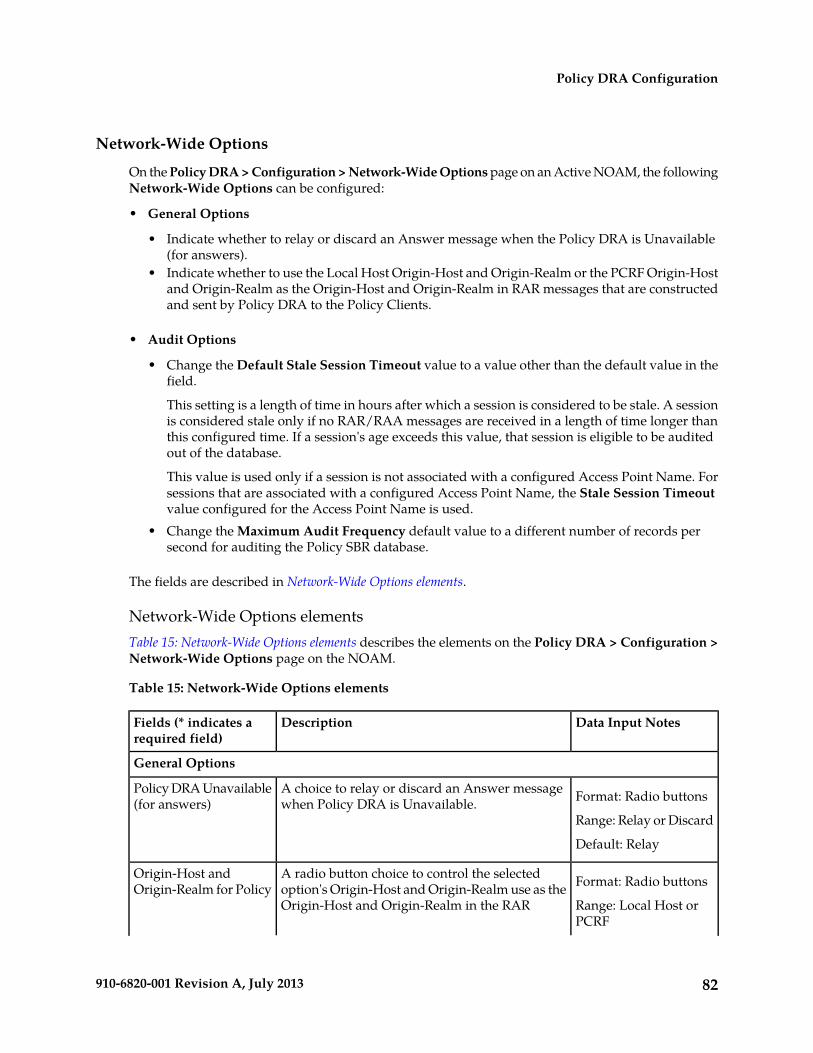
Network-Wide Options
On the Policy DRA > Configuration > Network-Wide Options page on an Active NOAM, the followingNetwork-Wide Options can be configured:
• General Options
• Indicate whether to relay or discard an Answer message when the Policy DRA is Unavailable(for answers).
• Indicate whether to use the Local Host Origin-Host and Origin-Realm or the PCRF Origin-Hostand Origin-Realm as the Origin-Host and Origin-Realm in RAR messages that are constructedand sent by Policy DRA to the Policy Clients.
• Audit Options
• Change the Default Stale Session Timeout value to a value other than the default value in thefield.
This setting is a length of time in hours after which a session is considered to be stale. A sessionis considered stale only if no RAR/RAA messages are received in a length of time longer thanthis configured time. If a session's age exceeds this value, that session is eligible to be auditedout of the database.
This value is used only if a session is not associated with a configured Access Point Name. Forsessions that are associated with a configured Access Point Name, the Stale Session Timeoutvalue configured for the Access Point Name is used.
• Change the Maximum Audit Frequency default value to a different number of records persecond for auditing the Policy SBR database.
The fields are described in Network-Wide Options elements.
Network-Wide Options elementsTable 15: Network-Wide Options elements describes the elements on the Policy DRA > Configuration >Network-Wide Options page on the NOAM.
Table 15: Network-Wide Options elements
Data Input NotesDescriptionFields (* indicates arequired field)
General Options
Format: Radio buttonsA choice to relay or discard an Answer messagewhen Policy DRA is Unavailable.
Policy DRA Unavailable(for answers)
Range: Relay or Discard
Default: Relay
Format: Radio buttonsA radio button choice to control the selectedoption's Origin-Host and Origin-Realm use as the
Origin-Host andOrigin-Realm for Policy
Range: Local Host orPCRF
Origin-Host and Origin-Realm in the RAR
82910-6820-001 Revision A, July 2013
Policy DRA Configuration
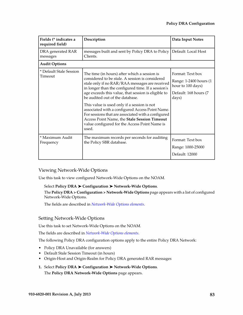
Data Input NotesDescriptionFields (* indicates arequired field)
messages built and sent by Policy DRA to PolicyClients.
DRA generated RARmessages
Default: Local Host
Audit Options
Format: Text boxThe time (in hours) after which a session isconsidered to be stale. A session is considered
* Default Stale SessionTimeout
Range: 1-2400 hours (1hour to 100 days)stale only if no RAR/RAA messages are received
in longer than the configured time. If a session'sDefault: 168 hours (7days)
age exceeds this value, that session is eligible tobe audited out of the database.
This value is used only if a session is notassociated with a configured Access Point Name.For sessions that are associated with a configuredAccess Point Name, the Stale Session Timeoutvalue configured for the Access Point Name isused.
Format: Text boxThe maximum records per seconds for auditingthe Policy SBR database.
* Maximum AuditFrequency
Range: 1000-25000
Default: 12000
Viewing Network-Wide OptionsUse this task to view configured Network-Wide Options on the NOAM.
Select Policy DRA ➤ Configuration ➤ Network-Wide Options.The Policy DRA > Configuration > Network-Wide Options page appears with a list of configuredNetwork-Wide Options.
The fields are described in Network-Wide Options elements.
Setting Network-Wide OptionsUse this task to set Network-Wide Options on the NOAM.
The fields are described in Network-Wide Options elements.
The following Policy DRA configuration options apply to the entire Policy DRA Network:
• Policy DRA Unavailable (for answers)• Default Stale Session Timeout (in hours)• Origin-Host and Origin-Realm for Policy DRA generated RAR messages
1. Select Policy DRA ➤ Configuration ➤ Network-Wide Options.The Policy DRA Network-Wide Options page appears.
83910-6820-001 Revision A, July 2013
Policy DRA Configuration

2. The Relay or Discard radio button setting is an engineered system value (uneditable) that controlsthe network option for the Policy DRA Unavailable (for answers) field.
3. Enter a number in the Default Stale Session Timeout Value field.4. Select the Local Host or PCRF radio button.
This sets the Origin-Host and Origin-Realm that will be used in the RAR messages constructedand sent by Policy DRA to policy clients.
5. Click:
• Apply to save the changes and remain on this page.• Cancel to discard changes and remain on the Policy DRA > Configuration > Network-Wide
Options page.
If Apply is clicked and the following condition exists, an error message appears:
• The entered Default Stale Session Timeout value contains invalid characters, is out of the allowedrange, or the field is empty.
Alarm Settings
Note: Alarm Settings are configurable only on Active NOAM servers, and are viewable on NOAMand SOAM servers.
On the Policy DRA > Configuration > Alarm Settings page on an SOAM, you can view the configuredAlarm Thresholds and Suppress indications.
Each alarm can be configured with Minor, Major, and Critical threshold percentages.
The fields are described in Alarm Settings elements.
On the Policy DRA > Configuration > Alarm Settings page on the NOAM, you can change the AlarmThresholds and the Suppress indications for the following alarms:
• DSR Application Ingress Message Rate
The DSR Application Ingress Message Rate alarm is raised when the average Policy DRA ingressmessages rate exceeds the configured Alarm Threshold. The thresholds are based on the engineeredsystem value for Ingress Message Capacity.
• Policy SBR Sessions Threshold Exceeded
The Policy SBR Sessions Threshold Exceeded alarm percent full is based on the number of Sessionrecords compared to an engineered maximum that varies according to the number of session PolicySBR Server Groups per mated pair chosen during Policy DRA feature activation.
The Policy SBR Sessions Threshold Exceeded alarm is raised when number of concurrent PolicySBR sessions exceeds the configured threshold.
• Policy SBR Bindings Threshold Exceeded
The Policy SBR Bindings Threshold Exceeded alarm measures the number of IMSI Anchor Keyrecords against an engineered maximum value that varies according to the number of bindingPolicy SBR Server Groups specified at Policy DRA feature activation.
The Policy SBR Bindings Threshold Exceeded alarm works similarly to the session capacity alarmexcept that the scope of the binding capacity alarm is network-wide.
84910-6820-001 Revision A, July 2013
Policy DRA Configuration
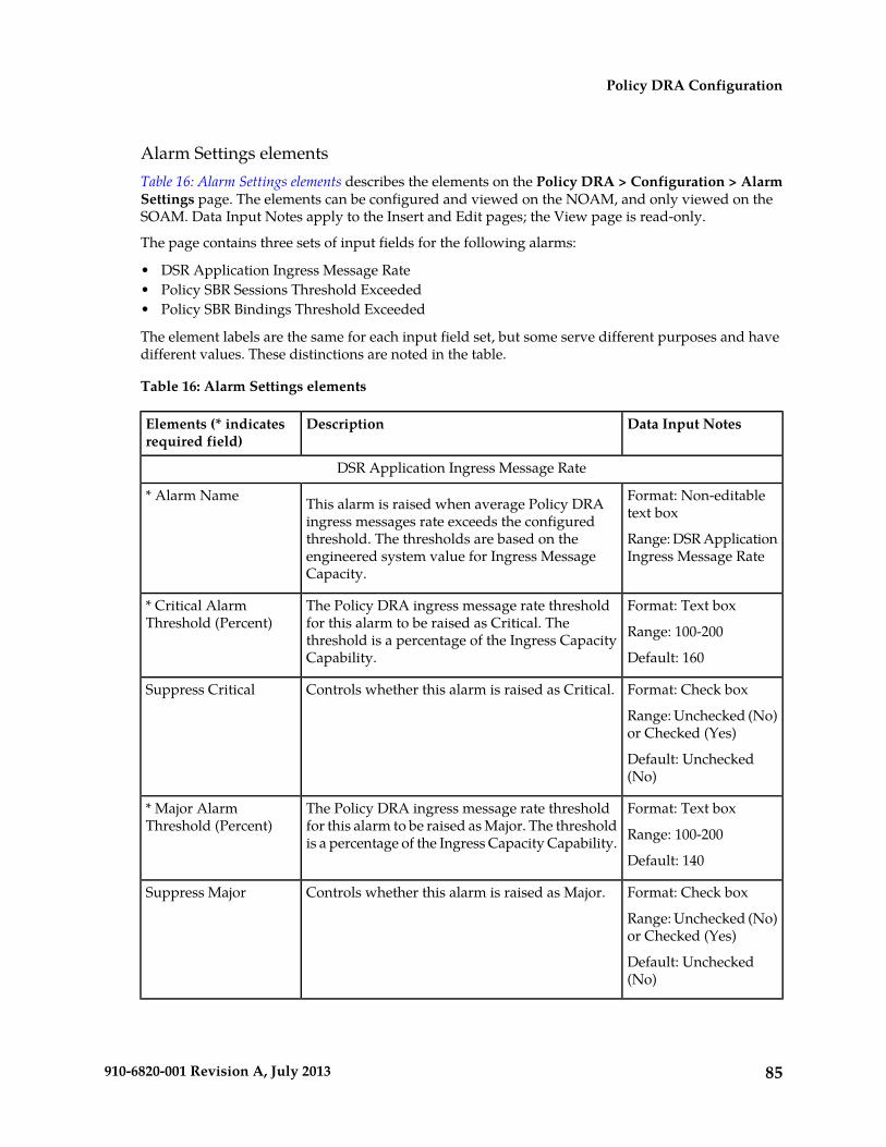
Alarm Settings elementsTable 16: Alarm Settings elements describes the elements on the Policy DRA > Configuration > AlarmSettings page. The elements can be configured and viewed on the NOAM, and only viewed on theSOAM. Data Input Notes apply to the Insert and Edit pages; the View page is read-only.
The page contains three sets of input fields for the following alarms:
• DSR Application Ingress Message Rate• Policy SBR Sessions Threshold Exceeded• Policy SBR Bindings Threshold Exceeded
The element labels are the same for each input field set, but some serve different purposes and havedifferent values. These distinctions are noted in the table.
Table 16: Alarm Settings elements
Data Input NotesDescriptionElements (* indicatesrequired field)
DSR Application Ingress Message Rate
Format: Non-editabletext box
Range: DSR ApplicationIngress Message Rate
This alarm is raised when average Policy DRAingress messages rate exceeds the configuredthreshold. The thresholds are based on theengineered system value for Ingress MessageCapacity.
* Alarm Name
Format: Text box
Range: 100-200
The Policy DRA ingress message rate thresholdfor this alarm to be raised as Critical. Thethreshold is a percentage of the Ingress CapacityCapability.
* Critical AlarmThreshold (Percent)
Default: 160
Format: Check box
Range: Unchecked (No)or Checked (Yes)
Controls whether this alarm is raised as Critical.Suppress Critical
Default: Unchecked(No)
Format: Text box
Range: 100-200
The Policy DRA ingress message rate thresholdfor this alarm to be raised as Major. The thresholdis a percentage of the Ingress Capacity Capability.
* Major AlarmThreshold (Percent)
Default: 140
Format: Check box
Range: Unchecked (No)or Checked (Yes)
Controls whether this alarm is raised as Major.Suppress Major
Default: Unchecked(No)
85910-6820-001 Revision A, July 2013
Policy DRA Configuration

Data Input NotesDescriptionElements (* indicatesrequired field)
Format: Text box
Range: 100-200
The Policy DRA ingress message rate thresholdfor this alarm to be raised as Minor. The thresholdis a percentage of the Ingress Capacity Capability.
* Minor AlarmThreshold (Percent)
Default: 110
Format: Check box
Range: Unchecked (No)or Checked (Yes)
Controls whether this alarm is raised as Minor.Suppress Minor
Default: Unchecked(No)
Policy SBR Sessions Threshold Exceeded
Format: Non-editabletext box
Range: Policy SBRSessions ThresholdExceeded
This alarm is raised when the number ofconcurrent Policy SBR sessions exceeds theconfigured threshold.
* Alarm Name
Format: Text box
Range: 1-99
The concurrent sessions threshold for this alarmto be raised as Critical. The threshold is apercentage of the Maximum Policy SBR Sessions.
* Critical AlarmThreshold (Percent)
Default: 95
Format: Check box
Range: Unchecked (No)or Checked (Yes)
Controls whether this alarm is raised as Critical.Suppress Critical
Default: Unchecked(No)
Format: Text box
Range: 1-99
The concurrent sessions threshold for this alarmto be raised as Major. The threshold is apercentage of the Maximum Policy SBR Sessions.
* Major AlarmThreshold (Percent)
Default: 90
Format: Check box
Range: Unchecked (No)or Checked (Yes)
Controls whether this alarm is raised as Major.Suppress Major
Default: Unchecked(No)
Format: Text box
Range: 1-99
The concurrent sessions threshold for this alarmto be raised as Minor. The threshold is apercentage of the Maximum Policy SBR Sessions.
* Minor AlarmThreshold (Percent)
Default: 80
86910-6820-001 Revision A, July 2013
Policy DRA Configuration
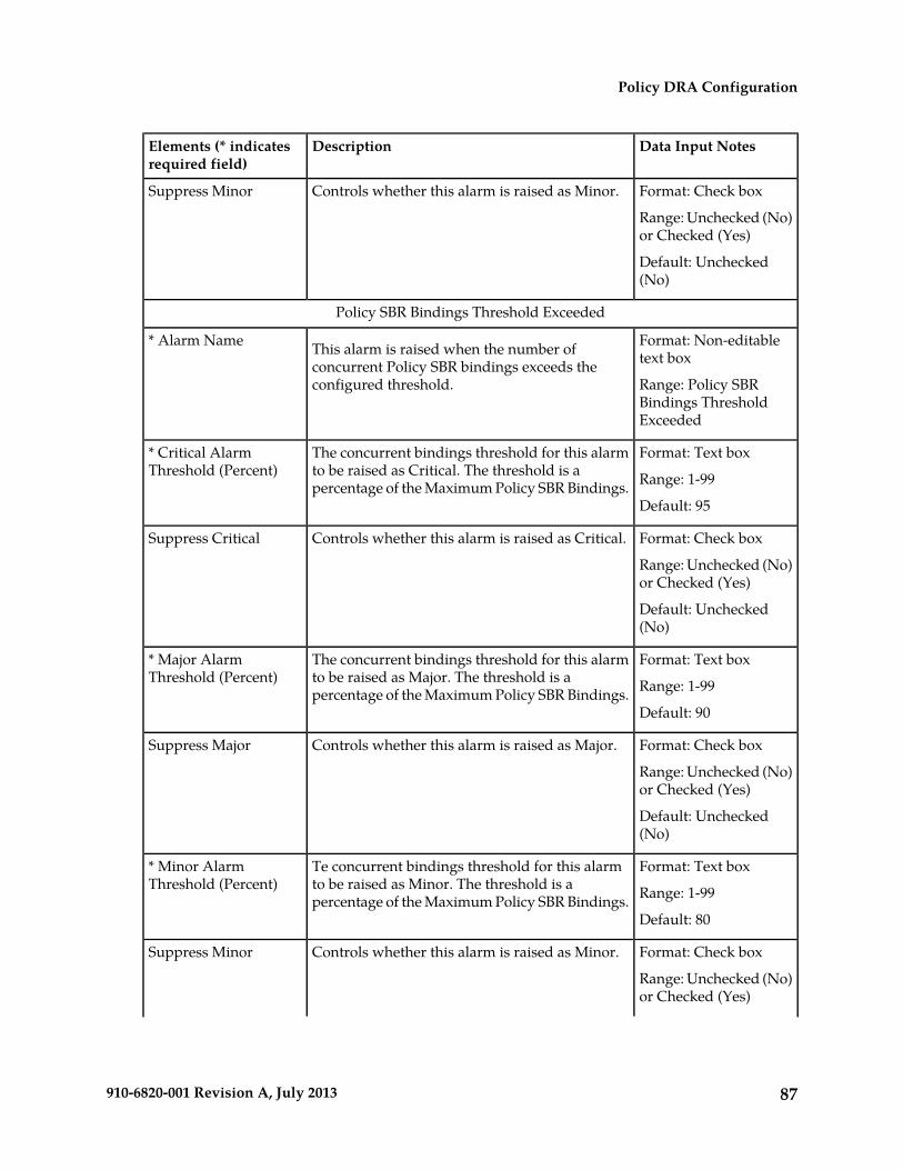
Data Input NotesDescriptionElements (* indicatesrequired field)
Format: Check box
Range: Unchecked (No)or Checked (Yes)
Controls whether this alarm is raised as Minor.Suppress Minor
Default: Unchecked(No)
Policy SBR Bindings Threshold Exceeded
Format: Non-editabletext box
Range: Policy SBRBindings ThresholdExceeded
This alarm is raised when the number ofconcurrent Policy SBR bindings exceeds theconfigured threshold.
* Alarm Name
Format: Text box
Range: 1-99
The concurrent bindings threshold for this alarmto be raised as Critical. The threshold is apercentage of the Maximum Policy SBR Bindings.
* Critical AlarmThreshold (Percent)
Default: 95
Format: Check box
Range: Unchecked (No)or Checked (Yes)
Controls whether this alarm is raised as Critical.Suppress Critical
Default: Unchecked(No)
Format: Text box
Range: 1-99
The concurrent bindings threshold for this alarmto be raised as Major. The threshold is apercentage of the Maximum Policy SBR Bindings.
* Major AlarmThreshold (Percent)
Default: 90
Format: Check box
Range: Unchecked (No)or Checked (Yes)
Controls whether this alarm is raised as Major.Suppress Major
Default: Unchecked(No)
Format: Text box
Range: 1-99
Te concurrent bindings threshold for this alarmto be raised as Minor. The threshold is apercentage of the Maximum Policy SBR Bindings.
* Minor AlarmThreshold (Percent)
Default: 80
Format: Check box
Range: Unchecked (No)or Checked (Yes)
Controls whether this alarm is raised as Minor.Suppress Minor
87910-6820-001 Revision A, July 2013
Policy DRA Configuration

Data Input NotesDescriptionElements (* indicatesrequired field)
Default: Unchecked(No)
Viewing Alarm SettingsUse this task to view configured Alarm-Settings on either the NOAM or SOAM.
Select Policy DRA ➤ Configuration ➤ Alarm Settings.The Policy DRA > Configuration > Alarm Settings page appears with a list of configured AlarmSettings.
The fields are described in Alarm Settings elements.
Defining Alarm SettingsUse this task to define Alarm Settings on an Active NOAM.
Note: Alarm Settings are configurable only on Active NOAM servers, and are viewable on NOAMand SOAM servers.
The fields are described in Alarm Settings elements.
1. Select Policy DRA ➤ Configuration ➤ Alarm Settings.The Policy DRA > Configuration > Alarm Settings page appears.
2. Enter values in the editable fields to define the alarm settings.3. Click:
• Apply to save the changes and remain on this page.• Cancel to discard the changes and remain on the Policy DRA > Configuration > Alarm Settings
page.
If Apply is clicked and any of the following conditions exist, an error message appears:
• The entered values contain the wrong data type or is out of the allowed range.• The value entered for Critical Alarm Threshold (Percent) is less than or equal to the value
entered for Major Alarm Threshold (Percent).• The value entered for Major Alarm Threshold (Percent) is less than or equal to the value entered
for Minor Alarm Threshold (Percent).
Congestion Options
Congestion Options are configurable on Active NOAM servers.
The following Congestion Options can be configured:
• Alarm Thresholds, which are used to:
• Set the percentage of the Policy DRA ingress message rate capacity at which an alarm is raisedwith Critical, Major, or Minor severity.
88910-6820-001 Revision A, July 2013
Policy DRA Configuration
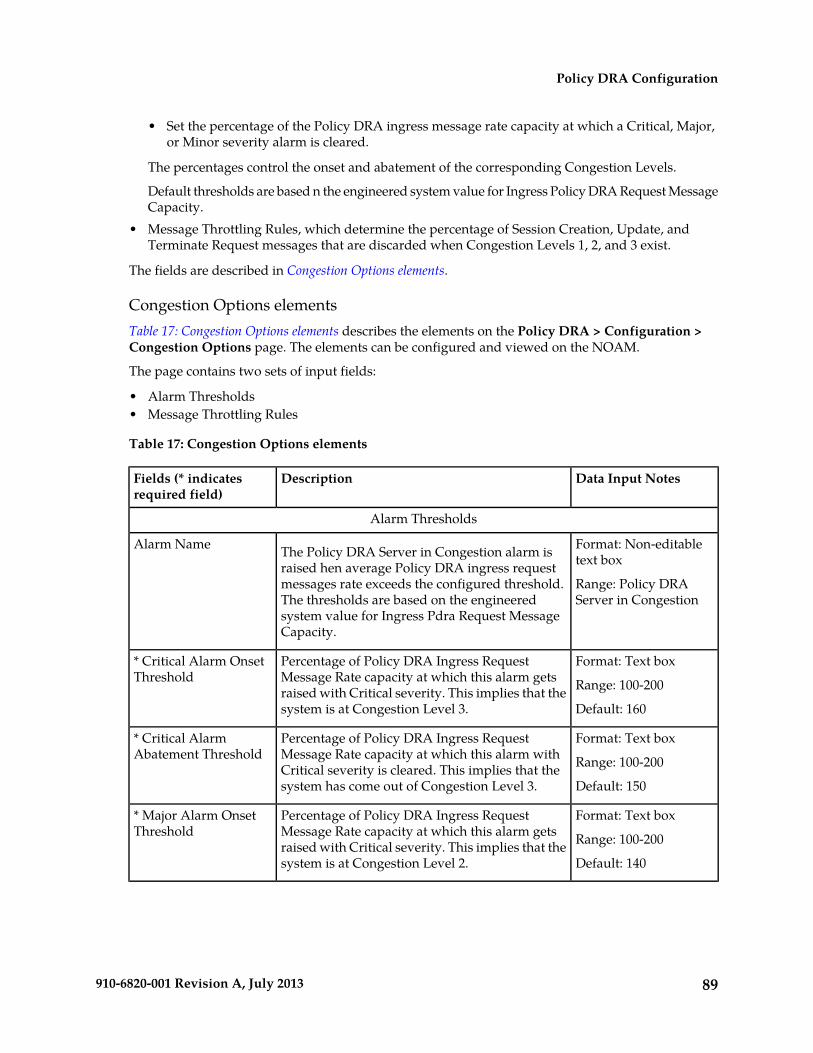
• Set the percentage of the Policy DRA ingress message rate capacity at which a Critical, Major,or Minor severity alarm is cleared.
The percentages control the onset and abatement of the corresponding Congestion Levels.
Default thresholds are based n the engineered system value for Ingress Policy DRA Request MessageCapacity.
• Message Throttling Rules, which determine the percentage of Session Creation, Update, andTerminate Request messages that are discarded when Congestion Levels 1, 2, and 3 exist.
The fields are described in Congestion Options elements.
Congestion Options elementsTable 17: Congestion Options elements describes the elements on the Policy DRA > Configuration >Congestion Options page. The elements can be configured and viewed on the NOAM.
The page contains two sets of input fields:
• Alarm Thresholds• Message Throttling Rules
Table 17: Congestion Options elements
Data Input NotesDescriptionFields (* indicatesrequired field)
Alarm Thresholds
Format: Non-editabletext box
Range: Policy DRAServer in Congestion
The Policy DRA Server in Congestion alarm israised hen average Policy DRA ingress requestmessages rate exceeds the configured threshold.The thresholds are based on the engineeredsystem value for Ingress Pdra Request MessageCapacity.
Alarm Name
Format: Text box
Range: 100-200
Percentage of Policy DRA Ingress RequestMessage Rate capacity at which this alarm getsraised with Critical severity. This implies that thesystem is at Congestion Level 3.
* Critical Alarm OnsetThreshold
Default: 160
Format: Text box
Range: 100-200
Percentage of Policy DRA Ingress RequestMessage Rate capacity at which this alarm withCritical severity is cleared. This implies that thesystem has come out of Congestion Level 3.
* Critical AlarmAbatement Threshold
Default: 150
Format: Text box
Range: 100-200
Percentage of Policy DRA Ingress RequestMessage Rate capacity at which this alarm getsraised with Critical severity. This implies that thesystem is at Congestion Level 2.
* Major Alarm OnsetThreshold
Default: 140
89910-6820-001 Revision A, July 2013
Policy DRA Configuration
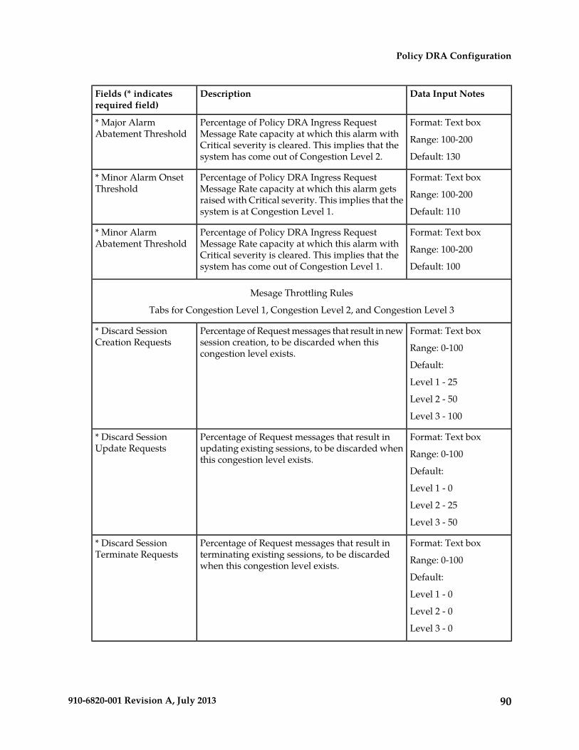
Data Input NotesDescriptionFields (* indicatesrequired field)
Format: Text box
Range: 100-200
Percentage of Policy DRA Ingress RequestMessage Rate capacity at which this alarm withCritical severity is cleared. This implies that thesystem has come out of Congestion Level 2.
* Major AlarmAbatement Threshold
Default: 130
Format: Text box
Range: 100-200
Percentage of Policy DRA Ingress RequestMessage Rate capacity at which this alarm getsraised with Critical severity. This implies that thesystem is at Congestion Level 1.
* Minor Alarm OnsetThreshold
Default: 110
Format: Text box
Range: 100-200
Percentage of Policy DRA Ingress RequestMessage Rate capacity at which this alarm withCritical severity is cleared. This implies that thesystem has come out of Congestion Level 1.
* Minor AlarmAbatement Threshold
Default: 100
Mesage Throttling Rules
Tabs for Congestion Level 1, Congestion Level 2, and Congestion Level 3
Format: Text box
Range: 0-100
Percentage of Request messages that result in newsession creation, to be discarded when thiscongestion level exists.
* Discard SessionCreation Requests
Default:
Level 1 - 25
Level 2 - 50
Level 3 - 100
Format: Text box
Range: 0-100
Percentage of Request messages that result inupdating existing sessions, to be discarded whenthis congestion level exists.
* Discard SessionUpdate Requests
Default:
Level 1 - 0
Level 2 - 25
Level 3 - 50
Format: Text box
Range: 0-100
Percentage of Request messages that result interminating existing sessions, to be discardedwhen this congestion level exists.
* Discard SessionTerminate Requests
Default:
Level 1 - 0
Level 2 - 0
Level 3 - 0
90910-6820-001 Revision A, July 2013
Policy DRA Configuration

Viewing Congestion OptionsUse this task to view configured Congestion Options on the NOAM.
Select Policy DRA ➤ Configuration ➤ Congestion Options.The Policy DRA > Configuration > Congestion Options page appears with a list of configuredCongestion Options.
The fields are described in Congestion Options elements.
Setting Congestion OptionsUse this task to set the following Congestion Options on the Active NOAM:
• Alarm Thresholds for the Policy DRA Server in Congestion onset and abatement alarm for Critical,Major, and Minor severities
• Message Throttling Rules for discarding Session Creation, Update, and Terminate Requests forCongestion Levels 1, 2, and 3
1. Select Policy DRA ➤ Configuration ➤ Congestion Options.The Policy DRA > Configuration > Congestion Options page appears.
2. Enter changes for the Alarm Thresholds.3. Enter changes for the Message Throttling Rules.4. Click:
• Apply to save the Congestion Options changes and refresh the page to show the changes.• Cancel to discard the changes and refresh the page.
If Apply is clicked and any of the following conditions exist, an error message appears:
• Any fields contain a value that contains invalid characters or is out of the allowed range.• Any required field is empty (not entered).• A Major Alarm Onset Threshold value is greater than the corresponding Critical Alarm Onset
Threshold.• A Minor Alarm Onset Threshold value is greater than the corresponding Major Alarm Onset
Threshold.• An Alarm Abatement Threshold value is greater than the corresponding Alarm Onset Threshold
of a particular severity.
PCRFs
The Policy DRA > Configuration > PCRFs page contains the list of PCRF Peer Nodes that are to beused when a new subscriber binding is created at this site. New bindings created at this Policy DRADSR are distributed evenly among the configured PCRFs.
PCRFs are responsible for authorizing and making policy decisions based on knowledge of subscriberresource usage and the capabilities allowed by the subscriber’s account. All policy requests for a givensubscriber must be routed to the same PCRF. The Policy DRA dynamically assigns subscribers toPCRFs using a load distribution algorithm, and maintains state about which subscribers are assignedto which PCRF. The relationship between a subscriber and a PCRF can change any time the subscriber
91910-6820-001 Revision A, July 2013
Policy DRA Configuration

transitions from having no Diameter policy sessions to having one or more Diameter policy sessions.After a policy session exists, all policy sessions for that subscriber are routed to the assigned PCRF.
The fields are described in PCRFs elements.
Note: For details about configuring Peer Nodes, refer to the Diameter and Mediation User Guide andDiameter online help.
On the Policy DRA > Configuration > PCRFs page on the SOAM, you can perform the followingactions:
• Filter the list of PCRFs, to display only the desired PCRFs.• Sort the list entries by column in ascending or descending order by clicking the column heading.
By default, the list is sorted by PCRFs in ascending numerical order.• Click the Insert button.
The Policy DRA > Configuration > PCRFs [Insert] page opens. You can add a PCRF. See InsertingPCRFs. If the maximum number of PCRFs (2500) already exists in the system, the Policy DRA >Configuration > PCRFs [Insert] page will not open, and an error message is displayed.
• Select a PCRF in the list, and click the Edit button.
The Policy DRA > Configuration > PCRFs [Edit] page opens. You can edit the selected PCRF. SeeEditing PCRFs.
• Select a PCRF in the list, and click the Delete button to remove the selected PCRF. See Deleting aPCRF.
PCRFs elementsTable 18: PCRFs page elements describes the elements on the Policy DRA > Configuration PCRFs page.Data Input Notes apply to the Insert and Edit pages; the View page is read-only.
Table 18: PCRFs page elements
Data Input NotesDescriptionFields (* indicatesrequired field)
Format: List
Range: ConfiguredDiameter Peer Nodes
The name of a configured Diameter Peer Nodethat identifies the PCRF Peer Node to be includedin the round-robin load distribution of newbindings to PCRFs.
Selecting a PCRF Peer Node name (bluehyperlink) displays the Diameter > Configuration
* PCRF Peer NodeName
Note: The PCRF PeerNode Name cannot bechanged on the [Edit]page.> Peer Nodes (Filtered) page where Diameter
Peer Nodes are filtered by the PCRF Peer NodeName.
Format: Text box
Range:0-64 characters
An optional comment to describe the PCRF PeerNode.
Comment
92910-6820-001 Revision A, July 2013
Policy DRA Configuration

Viewing PCRFsUse this task to view all configured PCRFs on the SOAM.
Select Policy DRA ➤ Configuration ➤ PCRFs.The Policy DRA > Configuration > PCRFs page appears with a list of configured PCRF PeerNodes.
The fields are described in PCRFs elements.
Inserting PCRFsUse this task to insert (create new) PCRFs.
The fields are described in PCRFs elements.
1. On the Active SOAM, select Policy DRA ➤ Configuration ➤ PCRFs.The Policy DRA > Configuration > PCRFs page appears.
2. Click Insert.The Policy DRA > Configuration > PCRFs [Insert] page opens.
3. Enter a unique PCRF Peer Node Name in the PCRF Peer Node Name field.This name uniquely identifies the PCRF Peer Node to be included in the round-robin loaddistribution of new bindings to PCRFs.
4. Enter an optional comment in the Comments field.5. Click:
• OK to save the new PCRF and return to the Policy DRA > Configuration > PCRFs page.• Apply to save the new PCRF and remain on this page.• Cancel to return to the Policy DRA > Configuration > PCRFs page without saving any changes.
If OK or Apply is clicked and any of the following conditions exist, an error message appears:
• The entered PCRF is not unique (already exists).• Any fields contain a value that contains invalid characters or is out of the allowed range.• Any required field is empty (not entered).• Adding the new PCRF would cause the maximum number of PCRFs (2500) to be exceeded.
Editing PCRFsUse this task to edit PCRF Comments.
Note: The PCRF Peer Node Name cannot be edited.
1. On the Active SOAM, select Policy DRA ➤ Configuration ➤ PCRFs.The Policy DRA > Configuration > PCRFs page appears. The page displays a list of the configuredPCRF Peer Nodes that are used when a new subscriber binding is created.
2. Click in the Comments field of the row to select the PCRF to edit.
93910-6820-001 Revision A, July 2013
Policy DRA Configuration
DO NOT click the blue PCRF Peer Node Name (unless you want to see the configuration of thePeer Node). The blue color indicates a hyper-link that opens the Diameter > Configuration > PeerNodes [Filtered] page to display the configuration information for the Peer Node.
3. Edit the Comments field for the selected PCRF.The PCRF Peer Node name cannot be changed.
4. Click:
• OK to save the change and return to the Policy DRA > Configuration > PCRFs page.• Apply to save the change and remain on this page.• Cancel to return to the Policy DRA > Configuration > PCRFs page without saving any changes.
If Apply or OK is clicked and the selected PCRF Peer Node Name entry no longer exists (wasdeleted by another user), an error message appears.
Deleting a PCRFUse the following procedure to delete a PCRF.
1. Select Policy DRA ➤ Configuration ➤ PCRFs.The Policy DRA > Configuration > PCRFs page appears.
2. Select the PCRF to be deleted.3. Click the Delete button.
A popup window appears to confirm the delete.
4. Click:
• OK to delete the PCRF.• Cancel to cancel the delete function and return to the Policy DRA > Configuration > PCRFs
page.
If OK is clicked and the selected PCRF no longer exists (it was deleted by another user), an errormessage is displayed and the PCRFs page is refreshed. The row that was selected is no longerdisplayed in the list.
Binding Key Priority
The Binding Key Priority defines search priorities for Alternative Keys that can be used to locate asubscriber binding.
The Binding Key Priority controls:
• Which keys are stored for binding correlation• The order in which keys are searched for purposes of binding correlation
The priority determines the order used to find a binding for subsequent sessions. Alternative Keyswith an assigned priority will be created with the binding if they are present in the session initiationmessage that created the binding. The Alternative Keys must be assigned a priority in order to be usedto locate subscriber bindings. If any Alternative Keys are not assigned a priority, they will not be usedto locate subscriber bindings even if the Alternative Key is present in the session initiation message.
The fields are described in Binding Key Priority elements.
94910-6820-001 Revision A, July 2013
Policy DRA Configuration
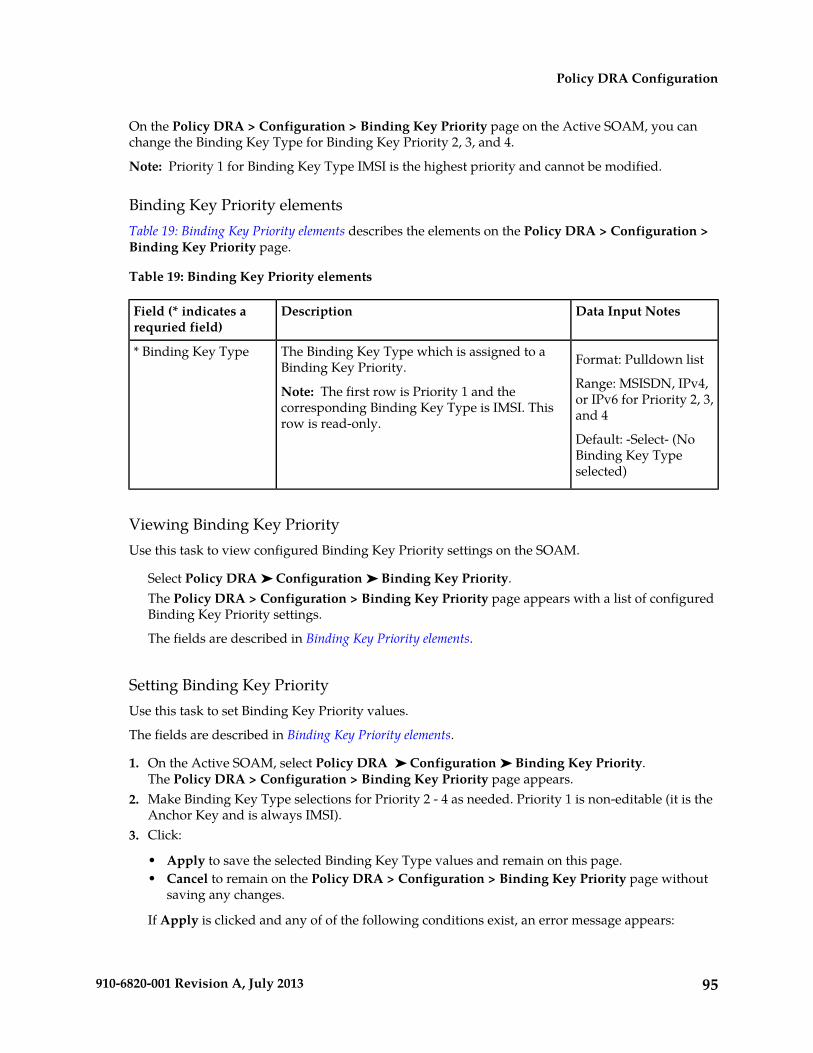
On the Policy DRA > Configuration > Binding Key Priority page on the Active SOAM, you canchange the Binding Key Type for Binding Key Priority 2, 3, and 4.
Note: Priority 1 for Binding Key Type IMSI is the highest priority and cannot be modified.
Binding Key Priority elementsTable 19: Binding Key Priority elements describes the elements on the Policy DRA > Configuration >Binding Key Priority page.
Table 19: Binding Key Priority elements
Data Input NotesDescriptionField (* indicates arequried field)
Format: Pulldown listThe Binding Key Type which is assigned to aBinding Key Priority.
Note: The first row is Priority 1 and thecorresponding Binding Key Type is IMSI. Thisrow is read-only.
* Binding Key Type
Range: MSISDN, IPv4,or IPv6 for Priority 2, 3,and 4
Default: -Select- (NoBinding Key Typeselected)
Viewing Binding Key PriorityUse this task to view configured Binding Key Priority settings on the SOAM.
Select Policy DRA ➤ Configuration ➤ Binding Key Priority.The Policy DRA > Configuration > Binding Key Priority page appears with a list of configuredBinding Key Priority settings.
The fields are described in Binding Key Priority elements.
Setting Binding Key PriorityUse this task to set Binding Key Priority values.
The fields are described in Binding Key Priority elements.
1. On the Active SOAM, select Policy DRA ➤ Configuration ➤ Binding Key Priority.The Policy DRA > Configuration > Binding Key Priority page appears.
2. Make Binding Key Type selections for Priority 2 - 4 as needed. Priority 1 is non-editable (it is theAnchor Key and is always IMSI).
3. Click:
• Apply to save the selected Binding Key Type values and remain on this page.• Cancel to remain on the Policy DRA > Configuration > Binding Key Priority page without
saving any changes.
If Apply is clicked and any of of the following conditions exist, an error message appears:
95910-6820-001 Revision A, July 2013
Policy DRA Configuration

• A Binding Key Priority Type is selected for more than one Priority• Binding Key Types are not selected for consecutive Priority values
Topology Hiding
Use the Policy DRA > Configuration > Topology Hiding page to define the list of Policy Client PeerNodes from which the PCRF name is to be hidden. This page can be used only if Topology Hiding isEnabled and the Topology Hiding Scope option is either Specific Hosts or All Foreign Realms +Specific Hosts on the Policy DRA > Configuration > Site Options page. See Site Options.
The fields are described in Topology Hiding elements.
On the Policy DRA > Configuration > Topology Hiding page, you can:
• Filter the list of Policy Client Peer Node Names, to display only the desired Policy Client Peer NodeNames.
• Sort the list entries in ascending or descending order by Policy Client Peer Node Names or byComments, by clicking the column heading. By default, the list is sorted by Policy Client Peer NodeNames in ascending numerical order.
• Click the Insert button.
The Policy DRA > Configuration > Topology Hiding [Insert] page opens. You can add a PolicyClient Peer Node Name and Comment. See Adding a new Policy Client for Topology Hiding. If themaximum number of Policy Client Peer Nodes (1000) already exists in the system, the Policy DRA> Configuration > Topology Hiding [Insert] page will not open, and an error message is displayed.
• Select the Comment cell in the row for a Policy Client Peer Node Name in the list, and click theEdit button. (Clicking the blue Policy Client Peer Node Name will open the filtered Diameter >Configuration > Peer Nodes page for the Peer Node.)
The Policy DRA > Configuration > Topology Hiding [Edit] page opens. You can edit the Commentfor the selected Policy Client Peer Node Name. (The Policy Client Peer Node Name cannot bechanged.)
• Select the Comment in the row for a Policy Client Peer Node Name in the list, and click the Deletebutton to remove the selected Policy Client Peer Node Name. See Deleting a Topology Hiding PolicyClient Peer Node.
Topology Hiding elementsTable 20: Topology Hiding elements describes the elements on the Policy DRA > Configuration >Topology Hiding page. Data Input Notes apply to the Insert and Edit pages; the View page is read-only.
Table 20: Topology Hiding elements
Data Input NotesDescriptionElements
Format: Pulldown listThe name of a configured Diameter Peer Nodethat identifies a Policy Client Peer Node.
Selecting a Policy Client Peer Node name (bluehyperlink) displays the Diameter > Configuration
Policy Client Peer NodeName
Note: The Policy ClientPeer Node Name cannotbe changed on the [Edit]page.> Peer Nodes (Filtered) page where Diameter
96910-6820-001 Revision A, July 2013
Policy DRA Configuration
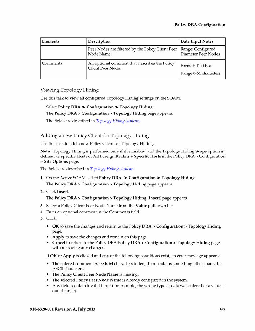
Data Input NotesDescriptionElements
Peer Nodes are filtered by the Policy Client PeerNode Name.
Range: ConfiguredDiameter Peer Nodes
Format: Text boxAn optional comment that describes the PolicyClient Peer Node.
Comments
Range 0-64 characters
Viewing Topology HidingUse this task to view all configured Topology Hiding settings on the SOAM.
Select Policy DRA ➤ Configuration ➤ Topology Hiding.The Policy DRA > Configuration > Topology Hiding page appears.
The fields are described in Topology Hiding elements.
Adding a new Policy Client for Topology HidingUse this task to add a new Policy Client for Topology Hiding.
Note: Topology Hiding is performed only if it is Enabled and the Topology Hiding Scope option isdefined as Specific Hosts or All Foreign Realms + Specific Hosts in the Policy DRA > Configuration> Site Options page.
The fields are described in Topology Hiding elements.
1. On the Active SOAM, select Policy DRA ➤ Configuration ➤ Topology Hiding.The Policy DRA > Configuration > Topology Hiding page appears.
2. Click Insert.The Policy DRA > Configuration > Topology Hiding [Insert] page appears.
3. Select a Policy Client Peer Node Name from the Value pulldown list.4. Enter an optional comment in the Comments field.5. Click:
• OK to save the changes and return to the Policy DRA > Configuration > Topology Hidingpage.
• Apply to save the changes and remain on this page.• Cancel to return to the Policy DRA Policy DRA > Configuration > Topology Hiding page
without saving any changes.
If OK or Apply is clicked and any of the following conditions exist, an error message appears:
• The entered comment exceeds 64 characters in length or contains something other than 7-bitASCII characters.
• The Policy Client Peer Node Name is missing.• The selected Policy Peer Node Name is already configured in the system.• Any fields contain invalid input (for example, the wrong type of data was entered or a value is
out of range).
97910-6820-001 Revision A, July 2013
Policy DRA Configuration

• The maximum number (1000) of Topology Hiding records has already been configured.
Editing Topology HidingUse this task to edit a Policy Client for Topology Hiding.
Note: Topology Hiding is performed only if it is also activated and the Topology Hiding Scope optionis defined as Specific Hosts or All Foreign Realms + Specific Hosts in the Policy DRA > Configuration> Site Options page.
The fields are described in Topology Hiding elements.
1. On the Active SOAM, select Policy DRA ➤ Configuration ➤ Topology Hiding.The Policy DRA > Configuration > Topology Hiding page appears.
2. Click Edit.The Policy DRA > Configuration > Topology Hiding [Edit] page appears.A read-only value is displayed in the Policy Client Peer Node Name Value field.
3. Edit or enter an optional comment in the Comments field.4. Click:
• OK to save the edited Comment and return to the Policy DRA > Configuration > TopologyHiding page.
• Apply to save the edited Comment and remain on this page.• Cancel to return to the Policy DRA > Configuration > Topology Hiding page without saving
any changes.
If OK or Apply is clicked and the following condition exists, an error message appears:
• The selected Policy Client Code Name no longer exists (for example, it has been deleted byanother user), and no changes are made to the database.
Deleting a Topology Hiding Policy Client Peer NodeUse the following procedure to delete a Topology Hiding Policy Client Peer Node.
1. Select Policy DRA ➤ Configuration ➤ Topology Hiding.The Policy DRA > Configuration > Topology Hiding page appears.
2. Select the Comment in the line for a Policy Client Peer Node Name to be deleted. (Clicking the bluePolicy Client Peer Node Name will open the filtered Diameter > Configuration > Peer Nodes pagefor the Peer Node.)
3. Click the Delete button.
A popup window appears to confirm the delete.
4. Click:
• OK to delete the Policy Client Peer Node Name.• Click Cancel to cancel the delete function and return to the Policy DRA > Configuration >
Topology Hiding page.
98910-6820-001 Revision A, July 2013
Policy DRA Configuration
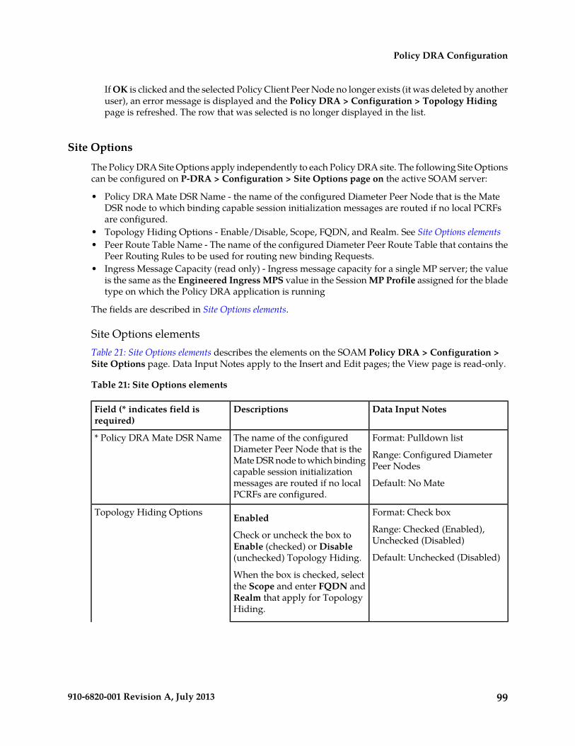
If OK is clicked and the selected Policy Client Peer Node no longer exists (it was deleted by anotheruser), an error message is displayed and the Policy DRA > Configuration > Topology Hidingpage is refreshed. The row that was selected is no longer displayed in the list.
Site Options
The Policy DRA Site Options apply independently to each Policy DRA site. The following Site Optionscan be configured on P-DRA > Configuration > Site Options page on the active SOAM server:
• Policy DRA Mate DSR Name - the name of the configured Diameter Peer Node that is the MateDSR node to which binding capable session initialization messages are routed if no local PCRFsare configured.
• Topology Hiding Options - Enable/Disable, Scope, FQDN, and Realm. See Site Options elements• Peer Route Table Name - The name of the configured Diameter Peer Route Table that contains the
Peer Routing Rules to be used for routing new binding Requests.• Ingress Message Capacity (read only) - Ingress message capacity for a single MP server; the value
is the same as the Engineered Ingress MPS value in the Session MP Profile assigned for the bladetype on which the Policy DRA application is running
The fields are described in Site Options elements.
Site Options elementsTable 21: Site Options elements describes the elements on the SOAM Policy DRA > Configuration >Site Options page. Data Input Notes apply to the Insert and Edit pages; the View page is read-only.
Table 21: Site Options elements
Data Input NotesDescriptionsField (* indicates field isrequired)
Format: Pulldown list
Range: Configured DiameterPeer Nodes
The name of the configuredDiameter Peer Node that is theMate DSR node to which bindingcapable session initialization
* Policy DRA Mate DSR Name
Default: No Matemessages are routed if no localPCRFs are configured.
Format: Check box
Range: Checked (Enabled),Unchecked (Disabled)
Enabled
Check or uncheck the box toEnable (checked) or Disable(unchecked) Topology Hiding.
Topology Hiding Options
Default: Unchecked (Disabled)
When the box is checked, selectthe Scope and enter FQDN andRealm that apply for TopologyHiding.
99910-6820-001 Revision A, July 2013
Policy DRA Configuration
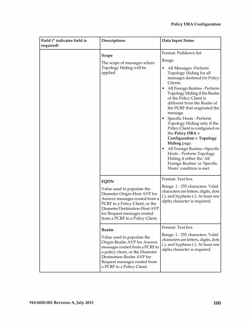
Data Input NotesDescriptionsField (* indicates field isrequired)
Format: Pulldown list
Range:Scope
The scope of messages whereTopology Hiding will beapplied.
• All Messages -PerformTopology Hiding for allmessages destined for PolicyClients.
• All Foreign Realms - PerformTopology Hiding if the Realmof the Policy Client isdifferent from the Realm ofthe PCRF that originated themessage.
• Specific Hosts - PerformTopology Hiding only if thePolicy Client is configured onthe Policy DRA >Configuration > TopologyHiding page.
• All Foreign Realms +SpecificHosts - Perform TopologyHiding if either the 'AllForeign Realms' or 'SpecificHosts' condition is met.
Format: Text box
Range: 1 - 255 characters. Validcharacters are letters, digits, dots
FQDN
Value used to populate theDiameter Origin-Host AVP for (.), and hyphens (-). At least one
alpha character is required.Answer messages routed from aPCRF to a Policy Client, or theDiameter Destination-Host AVPfor Request messages routedfrom a PCRF to a Policy Client.
Format: Text box
Range: 1 - 255 characters. Validcharacters are letters, digits, dots
Realm
Value used to populate theOrigin-Realm AVP for Answer (.), and hyphens (-). At least one
alpha character is required.messages routed from a PCRF toa policy client, or the DiameterDestination-Realm AVP forRequest messages routed froma PCRF to a Policy Client.
100910-6820-001 Revision A, July 2013
Policy DRA Configuration
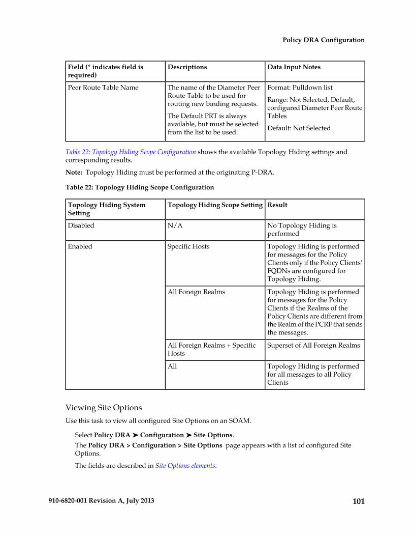
Data Input NotesDescriptionsField (* indicates field isrequired)
Format: Pulldown list
Range: Not Selected, Default,configured Diameter Peer RouteTables
The name of the Diameter PeerRoute Table to be used forrouting new binding requests.
The Default PRT is alwaysavailable, but must be selectedfrom the list to be used.
Peer Route Table Name
Default: Not Selected
Table 22: Topology Hiding Scope Configuration shows the available Topology Hiding settings andcorresponding results.
Note: Topology Hiding must be performed at the originating P-DRA.
Table 22: Topology Hiding Scope Configuration
ResultTopology Hiding Scope SettingTopology Hiding SystemSetting
No Topology Hiding isperformed
N/ADisabled
Topology Hiding is performedfor messages for the Policy
Specific HostsEnabled
Clients only if the Policy Clients’FQDNs are configured forTopology Hiding.
Topology Hiding is performedfor messages for the Policy
All Foreign Realms
Clients if the Realms of thePolicy Clients are different fromthe Realm of the PCRF that sendsthe messages.
Superset of All Foreign RealmsAll Foreign Realms + SpecificHosts
Topology Hiding is performedfor all messages to all PolicyClients
All
Viewing Site OptionsUse this task to view all configured Site Options on an SOAM.
Select Policy DRA ➤ Configuration ➤ Site Options.The Policy DRA > Configuration > Site Options page appears with a list of configured SiteOptions.
The fields are described in Site Options elements.
101910-6820-001 Revision A, July 2013
Policy DRA Configuration
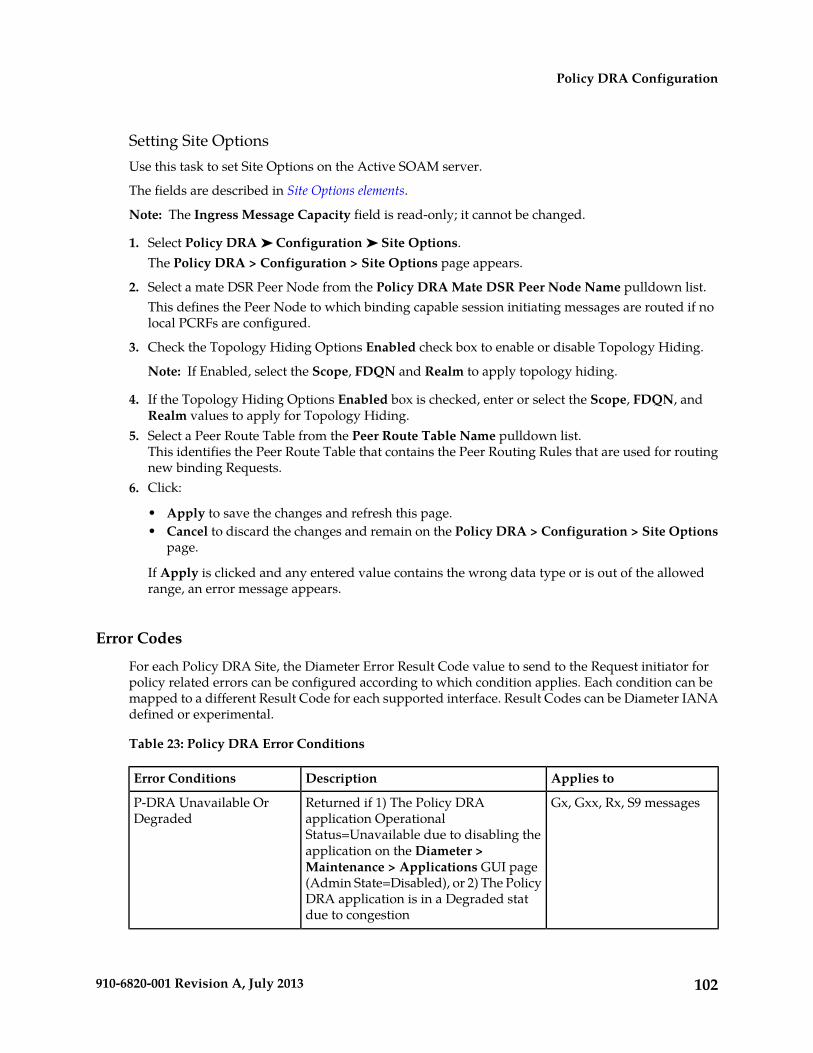
Setting Site OptionsUse this task to set Site Options on the Active SOAM server.
The fields are described in Site Options elements.
Note: The Ingress Message Capacity field is read-only; it cannot be changed.
1. Select Policy DRA ➤ Configuration ➤ Site Options.The Policy DRA > Configuration > Site Options page appears.
2. Select a mate DSR Peer Node from the Policy DRA Mate DSR Peer Node Name pulldown list.This defines the Peer Node to which binding capable session initiating messages are routed if nolocal PCRFs are configured.
3. Check the Topology Hiding Options Enabled check box to enable or disable Topology Hiding.
Note: If Enabled, select the Scope, FDQN and Realm to apply topology hiding.
4. If the Topology Hiding Options Enabled box is checked, enter or select the Scope, FDQN, andRealm values to apply for Topology Hiding.
5. Select a Peer Route Table from the Peer Route Table Name pulldown list.This identifies the Peer Route Table that contains the Peer Routing Rules that are used for routingnew binding Requests.
6. Click:
• Apply to save the changes and refresh this page.• Cancel to discard the changes and remain on the Policy DRA > Configuration > Site Options
page.
If Apply is clicked and any entered value contains the wrong data type or is out of the allowedrange, an error message appears.
Error Codes
For each Policy DRA Site, the Diameter Error Result Code value to send to the Request initiator forpolicy related errors can be configured according to which condition applies. Each condition can bemapped to a different Result Code for each supported interface. Result Codes can be Diameter IANAdefined or experimental.
Table 23: Policy DRA Error Conditions
Applies toDescriptionError Conditions
Gx, Gxx, Rx, S9 messagesReturned if 1) The Policy DRAapplication Operational
P-DRA Unavailable OrDegraded
Status=Unavailable due to disabling theapplication on the Diameter >Maintenance > Applications GUI page(Admin State=Disabled), or 2) The PolicyDRA application is in a Degraded statdue to congestion
102910-6820-001 Revision A, July 2013
Policy DRA Configuration
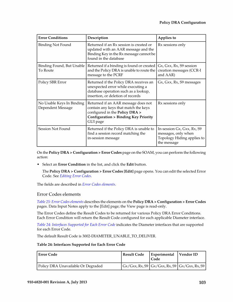
Applies toDescriptionError Conditions
Rx sessions onlyReturned if an Rx session is created orupdated with an AAR message and the
Binding Not Found
Binding Key in the Rx message cannot befound in the database
Gx, Gxx, Rx, S9 sessioncreation messages (CCR-Iand AAR)
Returned if a binding is found or createdand the Policy DRA is unable to route themessage to the PCRF
Binding Found, But UnableTo Route
Gx, Gxx, Rx, S9 messagesReturned if the Policy DRA receives anunexpected error while executing a
Policy SBR Error
database operation such as a lookup,insertion, or deletion of records
Rx sessions onlyReturned if an AAR message does notcontain any keys that match the keys
No Usable Keys In BindingDependent Message
configured in the Policy DRA >Configuration > Binding Key PriorityGUI page
In-session Gx, Gxx, Rx, S9messages, only when
Returned if the Policy DRA is unable tofind a session record matching thein-session message
Session Not Found
Topology Hiding applies tothe message
On the Policy DRA > Configuration > Error Codes page on the SOAM, you can perform the followingaction:
• Select an Error Condition in the list, and click the Edit button.
The Policy DRA > Configuration > Error Codes [Edit] page opens. You can edit the selected ErrorCode. See Editing Error Codes.
The fields are described in Error Codes elements.
Error Codes elementsTable 25: Error Codes elements describes the elements on the Policy DRA > Configuration > Error Codespages. Data Input Notes apply to the [Edit] page; the View page is read-only.
The Error Codes define the Result Codes to be returned for various Policy DRA Error Conditions.Each Error Condition will return the Result Code configured for each applicable Diameter interface.
Table 24: Interfaces Supported for Each Error Code indicates the Diameter interfaces that are supportedfor each Error Code.
The default Result Code is 3002-DIAMETER_UNABLE_TO_DELIVER.
Table 24: Interfaces Supported for Each Error Code
Vendor IDExperimentalCode
Result CodeError Code
Gx/Gxx, Rx, S9Gx/Gxx, Rx, S9Gx/Gxx, Rx, S9Policy DRA Unavailable Or Degraded
103910-6820-001 Revision A, July 2013
Policy DRA Configuration

Vendor IDExperimentalCode
Result CodeError Code
RxRxRxBinding Not Found
Gx/Gxx, Rx, S9Gx/Gxx, Rx, S9Gx/Gxx, Rx, S9Binding Found, But Unable To Route
Gx/Gxx, Rx, S9Gx/Gxx, Rx, S9Gx/Gxx, Rx, S9Policy SBR Error
RxRxRxNo Usable Keys In Binding Dependent Message
Gx/Gxx, Rx, S9Gx/Gxx, Rx, S9Gx/Gxx, Rx, S9Session Not Found
Table 25: Error Codes elements
Data Input NotesDescriptionFields (* indicatesrequired field)
View only; cannot beedited
The name of the selected Policy DRA ErrorCondition.
Error Condition
Format: Text boxThe Result Code to be returned on the Gx andGxx interfaces.
* Gx/Gxx Result Code
Range: 1-9999
Default: 3002
Format: Check boxDefines the Gx/Gxx Result Code as experimental.
Experimental codes require a correspondingVendor ID.
Gx/Gxx ExperimentalCode
Range: Yes (checked),(No) unchecked
Default: No (unchecked)
Format: Text boxThe Vendor ID that corresponds with theExperimental Code for the Gx and Gxx interfaces.
The Vendor ID '---' means the RFC standard errorcode will be sent.
Gx/Gxx Vendor ID
Range: 1-4294967295
Format: Text boxThe Result Code to be returned to the Rx interface.* Rx Result Code
Range: 1-9999
Default: 3002
Format: Check boxDefines the Rx Result Code as experimental.
Experimental Codes require a correspondingVendor ID.
Rx Experimental Code
Range: Yes (checked),(No) unchecked
Default: No (unchecked)
104910-6820-001 Revision A, July 2013
Policy DRA Configuration

Data Input NotesDescriptionFields (* indicatesrequired field)
Format: Text boxThe Vendor ID that corresponds with theExperimental Code for the Rx interface.
The Vendor ID '---' means the RFC standard errorcode will be sent.
Rx Vendor ID
Range: 1-4294967295
Format: Text boxThe Result Code to be returned to the S9 interface.* S9 Result Code
Range: 1-9999
Default: 3002
Format: Check boxDefines the S9 Result Code as experimental.
Experimental Codes require a correspondingVendor ID.
S9 Experimental Code
Range: Yes (checked),(No) unchecked
Default: No (unchecked)
Format: Text boxThe Vendor ID that corresponds with theExperimental Code for the S9 interface.
The Vendor ID '---' means the RFC standard errorcode will be sent.
S9 Vendor ID
Range: 1-4294967295
Viewing Error CodesUse this task to view configured Error Codes on the SOAM.
Select Policy DRA ➤ Configuration ➤ Error Codes.The Policy DRA > Configuration > Error Codes page appears with a list of configured Error Codes.The fields are described in Error Codes elements.
Editing Error CodesUse this task to edit Error Codes on the Active SOAM.
The fields are described in Error Codes elements.
1. Select Policy DRA ➤ Configuration ➤ Error Codes.The Policy DRA > Configuration > Error Codes page appears
2. Select the Error Condition that you want to edit.3. Click Edit.
The Policy DRA > Configuration > Error Codes [Edit] page opens
The fields that appear on the Policy DRA > Configuration > Error Codes [Edit] page are dependenton the Error Condition that was selected.
4. Edit the fields to define the selected Error Condition.5. Click:
105910-6820-001 Revision A, July 2013
Policy DRA Configuration

Ok to save the changes and return to the Policy DRA > Configuration > Error Codes page•• Apply to save the changes and remain on this page• Cancel to discard the changes and return to the Policy DRA > Configuration > Error Codes
page
If OK or Apply is clicked and any of the following conditions exist, an error message appears:
• Any required field value is missing (not entered or selected)• Any fields contain invalid input (for example, the wrong type of data was entered or a value is
out of range).
Post-Configuration Activities
After Policy DRA configuration is complete, the following activities need to be performed to makethe Policy DRA application fully operational in the system:
• Enable the Policy DRA application• Enable Diameter Connections with Peer Nodes• Status Verification
Enable the Policy DRA Application
Use this task to enable the Policy DRA application. For each Active SOAM,
1. Select Diameter ➤ Maintenance ➤ Applications.The Diameter > Maintenance > Applications page appears.
2. Under DSR Application Name, select each PDRA row.To select more than one row, press and hold Ctrl while you click each row.
3. Click Enable.4. Verify the application status on the page.
The Admin State, Operational Status, Operational Reason, and Congestion Level in each of theselected rows should change respectively to Enabled, Available, Normal, Normal.
Enable Connections
Use the following task to enable one or more connections to Peer Nodes.
1. At the Active SOAM, select Diameter ➤ Maintenance ➤ Connections.The Diameter > Maintenance > Connections page appears.
2. Select 1 - 20 connections to enable.To select multiple connections, press and hold the Ctrl key while you select each connection.
To select multiple contiguous connections, click the first connection you want, press and hold theShift key, and select the last connection you want. All the connections between are also selected.
3. Click Enable.
106910-6820-001 Revision A, July 2013
Policy DRA Configuration
A confirmation box appears.4. Click OK.
The selected connections are enabled.
If any of the selected connections no longer exist (they have been deleted by another user), an errormessage is displayed, but any selected connections that do exist are enabled.
5. Verify Connection status on the page.
Verify that the Admin State of all connections changes to Enabled and the Operational Reasonshows Connecting for connections to PCRF nodes and Listening for connections to other nodes(such as policy clients - PCEF, AF, and others). nodes.
For connections of type Responder Only (Policy Client nodes), the Operational Status andOperational Reason will be “Unk” if IPFE TSA connections are used.
Status Verification
Use the following task to verify Policy DRA and Policy SBR status after configuration is complete.
1. Verify Communication Agent (ComAgent) HA Services Status.a) At the Active NOAM, select Communication Agent ➤ Maintenance ➤ Connection Status.b) Verify that Resource Routing Status is Available for all listed User/Provider entries.
2. Verify the ComAgent Automatic Connection Status.a) At the Active NOAM, select Communication Agent ➤ Maintenance ➤ Ha Services Statusb) Verify that Automatic Connection Count is X of Y In Service, where Y >= X and X = Y indicate
successful Automatic Connection setup.
3. Verify Policy SBR Status.a) At the Active NOAM, select Policy DRA ➤ Maintenance ➤ Policy SBR Status.b) Verify that the server Resource HA Role is Active/Standby/Spare and Congestion Level is
Normal for all Servers in each Server Group in the Binding Region and Mated Site tab entries.
DSR Bulk Export
The DSR Bulk Export operation creates ASCII Comma-Separated Values (CSV) files (.csv) containingDiameter and DSR Application configuration data. Exported configuration data can be edited andused with the DSR Bulk Import operations to change the configuration data in the local system withoutthe use of GUI pages. The exported files can be transferred to and used to configure another DSRsystem.
Exported CSV Files
Each exported CSV file contains one or more records for the configuration data that was selected forthe Export operation.
CSV file formats and procedures for using Bulk Export operations are in the Diameter ConfigurationBulk Import Help and in the Diameter and Mediation User Guide.
107910-6820-001 Revision A, July 2013
Policy DRA Configuration

The selected configuration data can be exported once immediately, or can be periodically automaticallyexported on a defined schedule.
• Configuration data refers to any data that is configured for one of the Export Application types(FABR, RBAR, P-DRA, CPA, and SBR DSR Applications, and the Diameter Configuration menufolder).
• For the "Diameter" Export Application type, configuration data refers to any data that is configuredusing the GUI pages that are available from the Diameter Configuration folder.
Note: Diameter Mediation configuration data cannot be exported with DSR Bulk Export; Mediationhas its own Import and Export functions.
The following configuration data can be exported in one Export operation:
• All exportable configuration data in the system• All exportable configuration data from the selected Export Application• Exportable configuration data from a selected configuration component for the selected Export
Application
When ALL is selected, the exported data for each configuration component appears in a separate .csvfile.
For data that is exported once immediately, the default Output File Name has the following format;the name can be changed and is not required to keep this format:NeName_Timestamp-TimeZone_ApplicationType_ReportType.csv.
For data that is scheduled to be exported periodically, the default Task Name is DSR ConfigurationExport; the name can be changed.
All exported .csv files contain a comment header with the following information:
• Software revision used to generate the exported file• Date and Time file was generated• Name of selected Data object(s) exported• Total number of exported records
The following example illustrates how the export file header might appear, but it might not lookexactly as shown:################################################################################### Tekelec DSR Software Revision: xxxx# Date/Time Generated: mm/dd/yy hh:mm:ss# Exported Application: <ApplicationType># Exported Object: <ObjectType># Number of Records: nnn##################################################################################
Export Operations
Exported files can be written to the File Management Directory in the Status & Manage File Managementarea (see the Status &Manage Files page) or to the Export Server Directory.
Files that are created by a DSR Bulk Export operation must be in the local File Management area beforethey can be used for Bulk Import operations. See DSR Bulk Import.
For files that are exported to the local File Management Directory,
108910-6820-001 Revision A, July 2013
Policy DRA Configuration
• The files appear in the File Management area list on the local system (see the Status & ManageFiles page) and in the list on the Diameter Configuration Import page.
• These files can be used for Import operations on the local system.
For files that are exported to the local Export Server Directory,
• If a remote Export Server has been configured (see Administration > Export Server), the files inthe local Export Server Directory are transferred to the configured remote Export Server locationand are deleted from the local Export Server Directory. These transferred files do not appear in theFile Management area on the local system, and cannot be used for Import operations on the localsystem.
• If a remote Export Server has not been configured, the files in the local Export Server Directoryappear in the list on the Status & Manage Tasks Active Tasks page and in the File Managementarea list on the local system. These files can be used for Import operations on the local system.
Export Results
The result of each Bulk Export operation is logged into a file with the same name as the exported file,but with extension .log. The log file appears in the File Management area. The log file contains thenames of the selected configuration data components, the number of records exported for eachconfiguration component, and either the first error or all errors that occurred during the Exportoperation.
DSR Bulk Import
The DSR Bulk Import operations use configuration data in ASCII Comma-Separated Values (CSV)files (.csv), to insert new data into, update existing data in, or delete existing data from the DiameterConfiguration or DSR Applications (FABR, RBAR, P-DRA, and CPA/SBR ) Configuration data in thesystem.
Import CSV Files
Import CSV files can be created by using a DSR Bulk Export operation, or can be manually createdusing a text editor.
CSV file formats and procedures for using Bulk Import operations are in the Diameter ConfigurationImport Help and in the Diameter and Mediation User Guide.
CAUTION: The format of each Import CSV file record must be compatible with theconfiguration data in the current DSR release in the system.
• Configuration data refers to any data that is configured for one of the Export Application types(FABR, RBAR, P-DRA, CPA, and SBR DSR Applications; and the Diameter Configurationcomponents).
• For the "Diameter" Export Application type, configuration data refers to any data that is configuredusing the GUI pages that are available from the Diameter Configuration menu folder.
Note: Diameter Mediation configuration data cannot be imported with DSR Bulk Import operations;Mediation has its own Import and Export functions.
109910-6820-001 Revision A, July 2013
Policy DRA Configuration

• Each file can contain one or more records of the same format (for one configuration component,such as records for several Diameter Configuration Connections); the entire format for each recordmust be contained in one line of the file.
Files that are created using the DSR Bulk Export operation can be exported either to the Status &Manage File Management Directory (Status & Manage Files page), or to the local Export ServerDirectory.
For files that are exported to the Export Server Directory,
• If a remote Export Server has been configured (see the Administration Export Server page), thefiles in the Export Server Directory are automatically transferred to the configured remote ExportServer and are deleted from the Export Server Directory. The transferred files do not appear in thelist on the local system Status & Manage Files page or in the list on the Diameter ConfigurationImport page.
• If a remote Export Server has not been configured, the files in the Export Server Directory appearin the list on the Status & Manage Tasks Active Tasks page, and also appear in the list on the localsystem Status & Manage Files page.
For files that are exported to the File Management Directory,
• The files appear in the File Management area list on the local system Status & Manage Files pageand in the list on the Diameter Configuration Import page.
• The files can be downloaded, edited, uploaded, and used for Import operations.
• Import CSV files must be in the File Management area of the local system before they can beused for Import operations on the local system.
• The Download function on the Status & Manage Files page can be used to download the filesto a location off of the local system for editing or transfer to another system.
• The Upload function on the Status & Manage Files page can be used to upload the files to theFile Management area of the local system.
For files that are created manually using a text editor on a computer,
• Import CSV files that are located off of the local system must be uploaded to the File Managementarea of the local system before they can be used for Import operations on the local system.
• The Upload function on the Status & Manage Files page can be used to upload the files to the FileManagement area of the local system.
Import Operations
CAUTION: Bulk Import can degrade the performance of the DA-MP and should beperformed only in the maintenance window.
The CSV files that are used for Import operations must be in the local File Management area. TheDiameter Configuration Import page lists all files in the File Management area (on the Status &Manage Files page) that have the .csv file extension.
The File Management button on the Diameter Configuration Import page opens the Status & ManageFiles page.
The following Import operations can be performed:
110910-6820-001 Revision A, July 2013
Policy DRA Configuration

Note: The Application Type, Keyword, and Key fields in each file record are used to identify theconfiguration data entry in the system.
• Insert new configuration data into the system
Only data records that do not currently exist in the system are inserted. Any records in the file thatdo already exist in the system are treated and logged as failures.
• Update existing configuration data in the system
Only data records that currently exist in the system can be updated. Any records in the file that donot already exist in the system, and any records that already exist in the system but are not updatedin the file, are treated and logged as failures.
• Delete existing configuration data from the system
Only data records that currently exist in the system can be deleted. Any records in the file that donot exist in the system, and any records that exist in the system but are not changed in the file, aretreated and logged as failures.
For the Import operation on each record in a file to be successful with no errors logged for the operation,each record must be valid for the configuration data format and for the Import operation that is beingperformed.
• Exported configuration data probably needs to be edited before the exported file is used for anImport operation on the same system.
Insert operations - Records need to be added or edited to be able to insert new configuration dataentries (such as connections or Route Lists). It is best to remove from the file any records for existingconfiguration data entries; they will be flagged as errors for an Insert operation. It might be difficultto distinguish between logged errors for existing data and for the records for the new entries.
Update operations – Records need to be edited to change element values in existing configurationdata entries. The Application Type, Keyword, and Key fields are NOT changed in the records, sothat the entries can be identified as existing in the system. It is best to remove from the file anyrecords for existing configuration data entries that are NOT being updated; they will be flaggedas errors for an Insert operation. It might be difficult to distinguish between logged errors forexisting records that are not updated and for the updated records.
Delete operations – Using an exported file without editing it will remove from the system all ofthe configuration data entries in the exported records. If you do not want to delete all of theconfiguration data entries that are in the file records, edit the file and remove the records for theentries that are NOT to be deleted. Records for configuration data entries that do not exist in thesystem will be flagged as errors for a Delete operation. For example, if you want to delete 20 of 100configured connections, edit the file and remove the records for the 80 connections that you do notwant to delete.
• Files that were created using the DSR Bulk Export operation and are transferred to another systemfor importing configuration data on that other system may not need to be edited. Exceptions mightbe system-specific information such as IP addresses and DA-MP profiles.
• Manually created files can be created so that they contain only the configuration data that is neededfor the desired Import operation.
The files can be edited later for use with a different Import operation.
Manually created CSV files are not required to contain a comment header. If a comment header isincluded in the file, it must be formatted using pound signs (#), as shown in the Export file headerthat is described in Export Results.
111910-6820-001 Revision A, July 2013
Policy DRA Configuration
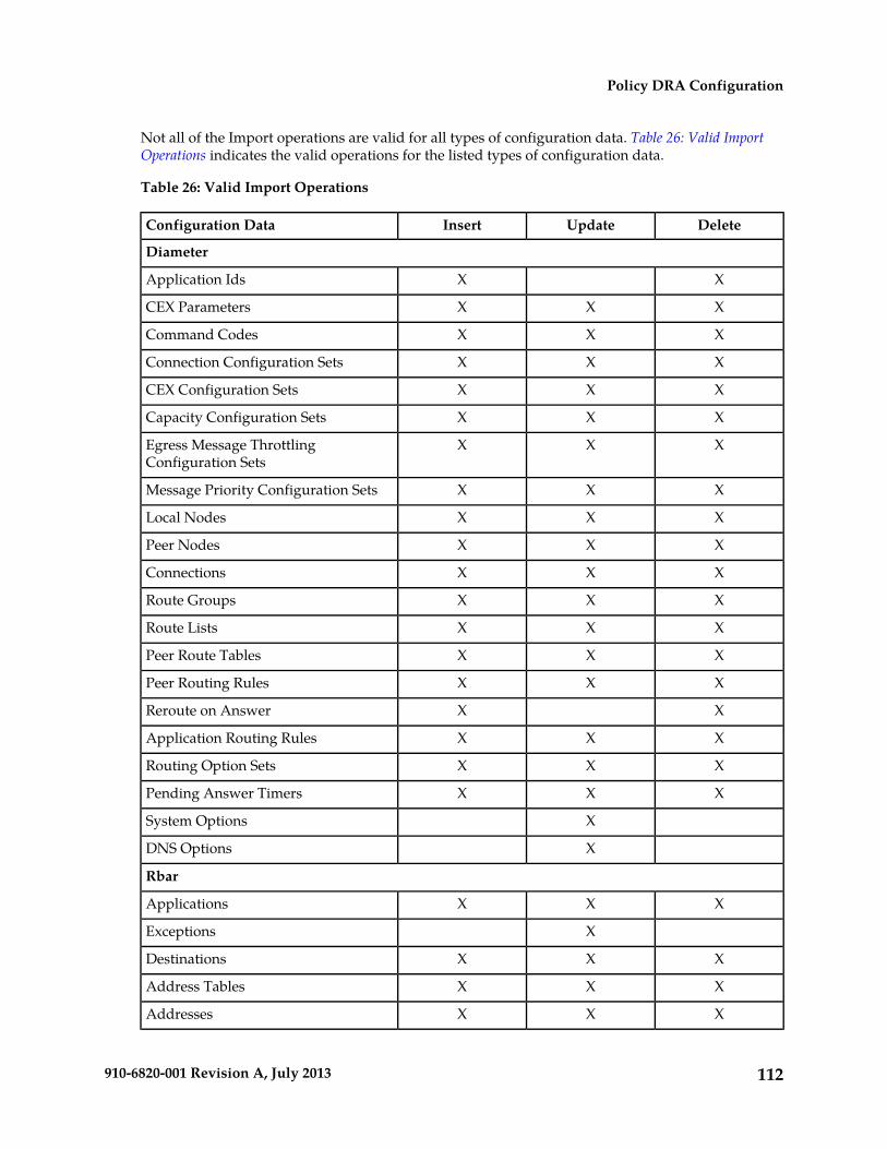
Not all of the Import operations are valid for all types of configuration data. Table 26: Valid ImportOperations indicates the valid operations for the listed types of configuration data.
Table 26: Valid Import Operations
DeleteUpdateInsertConfiguration Data
Diameter
XXApplication Ids
XXXCEX Parameters
XXXCommand Codes
XXXConnection Configuration Sets
XXXCEX Configuration Sets
XXXCapacity Configuration Sets
XXXEgress Message ThrottlingConfiguration Sets
XXXMessage Priority Configuration Sets
XXXLocal Nodes
XXXPeer Nodes
XXXConnections
XXXRoute Groups
XXXRoute Lists
XXXPeer Route Tables
XXXPeer Routing Rules
XXReroute on Answer
XXXApplication Routing Rules
XXXRouting Option Sets
XXXPending Answer Timers
XSystem Options
XDNS Options
Rbar
XXXApplications
XExceptions
XXXDestinations
XXXAddress Tables
XXXAddresses
112910-6820-001 Revision A, July 2013
Policy DRA Configuration
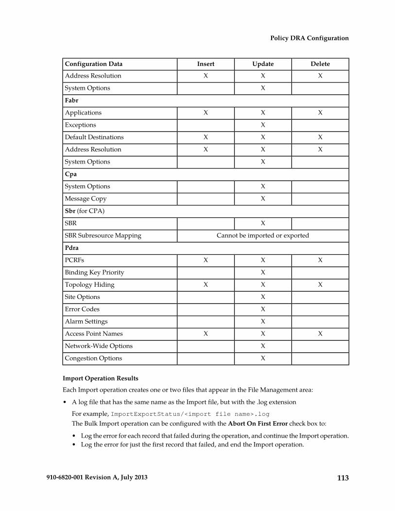
DeleteUpdateInsertConfiguration Data
XXXAddress Resolution
XSystem Options
Fabr
XXXApplications
XExceptions
XXXDefault Destinations
XXXAddress Resolution
XSystem Options
Cpa
XSystem Options
XMessage Copy
Sbr (for CPA)
XSBR
Cannot be imported or exportedSBR Subresource Mapping
Pdra
XXXPCRFs
XBinding Key Priority
XXXTopology Hiding
XSite Options
XError Codes
XAlarm Settings
XXXAccess Point Names
XNetwork-Wide Options
XCongestion Options
Import Operation Results
Each Import operation creates one or two files that appear in the File Management area:
• A log file that has the same name as the Import file, but with the .log extension
For example, ImportExportStatus/<import file name>.logThe Bulk Import operation can be configured with the Abort On First Error check box to:
• Log the error for each record that failed during the operation, and continue the Import operation.• Log the error for just the first record that failed, and end the Import operation.
113910-6820-001 Revision A, July 2013
Policy DRA Configuration

Information for records that succeed is not included in the log. The log file contains the Action(Import operation) that was performed; and the number of Successful Operations (records), FailedOperations (records), and Total Operations (records).
• A Failures file, if failures occurred during the Import operation
The file is a .csv with the same name as the Import file, but contains _Failures in the file name.
For example, if the Import file name is October_2_SO_DSR1_Diameter_CmdCodes.csv, theFailures file is named October_2_SO_ DSR1_Diameter_CmdCodes_Failures.csv
A Failures file can be downloaded from the local File Management area to a computer off the localsystem, edited to correct each record that failed, uploaded to the local system File Managementarea, and used again to repeat the Import operation and successfully process the records.
114910-6820-001 Revision A, July 2013
Policy DRA Configuration
Chapter
5Policy DRA Maintenance
This chapter describes or indicates where to findthe following information that can be used for thePolicy DRA application and Policy SBR:
Topics:
• Introduction.....116• Policy DRA Maintenance Pages.....116 • Maintenance and status information that is
maintained by the Policy DRA Configuration• Alarms, KPIs, and Measurements.....118• Binding and Session Database Auditing.....121 and Maintenance components and displayed on
the Policy DRA > Maintenance pages.• Overload Management.....125• Shutdown.....128 • Maintenance and status data that is maintained
by Diameter for Diameter Configuration• Diameter Maintenance and Status Data forComponents, DSR Applications, andDA-MPs.....129
components, DSR Applications, and DA-MPsand displayed on the Diameter MaintenanceGUI pages.• Backup and Restore for Policy DRA Configuration
Data.....130 • Descriptions of Policy DRA and Policy SBRalarms, KPIs, and measurements
• Auditing of the Session and Binding databases• Policy DRA and Policy SBR overload
management• Database Backup and Restore of Policy DRA
configuration data
115910-6820-001 Revision A, July 2013
Introduction
This chapter describes:
• Policy DRA Maintenance Pages describes maintenance and status data that is maintained by thePolicy DRA application and by Policy DRA DA-MPs.
On the P-DRA > Maintenance pages you can:
• View Policy SBR Status• Define and execute a Binding Key Query
• Diameter Maintenance and Status Data for Components, DSR Applications, and DA-MPs describesmaintenance and status information that is maintained by the Diameter Routing Function and theDiameter Transport Function for the Diameter Configuration components that are used to makeegress Request message routing decisions.
The Diameter > Maintenance pages include status information for:
• Peer Nodes• Connections• DSR Applications (including Policy DRA)• DA-MPs
• Alarms, KPIs, and Measurementsdescribes Policy DRA-specific database alarms, and indicates thelocation of descriptions of Policy DRA and Policy SBR alarms, KPIs, and measurements.
• Binding and Session Database Auditing describes the auditing of the Session and Binding databases.• Overload Management describes overload controls and load shedding and for Policy DRA and Policy
SBR.• Backup and Restore for Policy DRA Configuration Data describes the OAM database backup and restore
of Policy DRA configuration data.
Policy DRA Maintenance Pages
The Policy DRA > Maintenance GUI pages on the NOAM display Policy SBR status information andprovide access to the Binding :Key Query tool.
Policy SBR Status
The Policy DRA > Maintenance > Policy SBR Status page displays a collapsed or expanded detailedreport for Policy SBR. The data is displayed within Server Groups by configured Place Associations.Each line on the page represents a Server Group.
Fields are described in Policy SBR Status elements.
116910-6820-001 Revision A, July 2013
Policy DRA Maintenance

Policy SBR Status elementsTable 27: Policy SBR Status elements describes the elements on the Policy SBR Status page, whichdisplays Policy SBR Server Status data within Server Groups that are assigned to each type of PlaceAssociation.
Each tab name was configured on the Configuration > Place Associations GUI page.
Table 27: Policy SBR Status elements
Data Input NotesDescriptionElements
The page is view-only.A list of all configured Server Groups that areassigned to the Binding Region Place Association.
One <Binding Region>tab
The Server Group ineach row under the tabThe Resource Domain Name and the Resource
Domain Profile of each Server Group is shown. can be expanded orcollapsed by clicking onThe Resource HA Role of the Server, the server's
Congestion Level, and a list of Sub Resources the + symbol, to list theServers that areHosted by the server are shown for each Server
in the expanded list. assigned to that ServerGroup.
Each tab displays a list of all configured ServerGroups that are assigned to that Mated Pair PlaceAssociation.
A tab for each PolicyDRA Mated Site in thesystem
The Resource Domain Name and the ResourceDomain Profile of each Server Group are shown.
The Resource HA Role of the Server, the server'sCongestion Level, and a list of Sub ResourcesHosted by the server are shown for each Serverin the expanded list.
Binding Key Query
Use the Policy DRA > Maintenance > Binding Key Query page to enter a value for an individualquery for a specified binding key. The tool queries the Binding database to determine if the bindingkey exists.
• If the binding key exists, a report is generated that includes the PCRF that the key is bound to andinformation about which Diameter session or sessions are associated with that binding key.
The returned session information includes all other binding keys that were included in the session,the session creation time, and the session last touched time.
• If the queried binding key does not exist, an error message is displayed..
Note: The Binding Key Query tool can be used only with Gx sessions. It is not applicable to Rx sessions.
The fields are described in Binding Key Query elements.
To use the Binding Key Query tool,
117910-6820-001 Revision A, July 2013
Policy DRA Maintenance
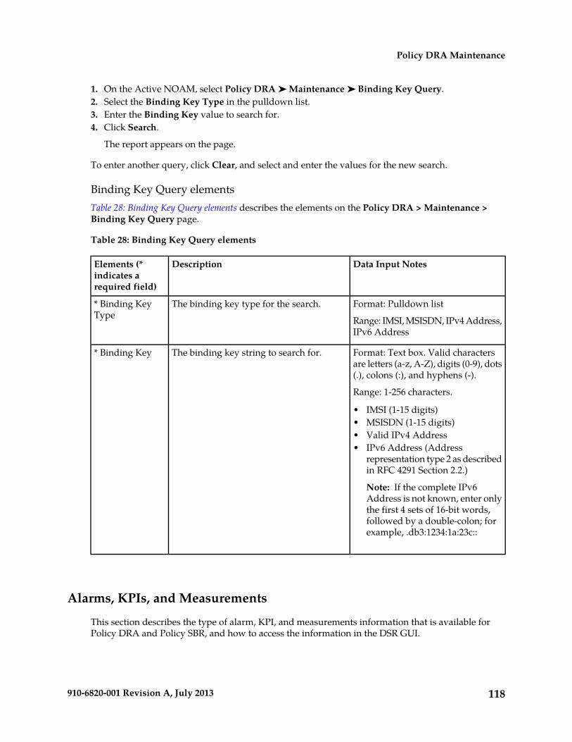
1. On the Active NOAM, select Policy DRA ➤ Maintenance ➤ Binding Key Query.2. Select the Binding Key Type in the pulldown list.3. Enter the Binding Key value to search for.4. Click Search.
The report appears on the page.
To enter another query, click Clear, and select and enter the values for the new search.
Binding Key Query elementsTable 28: Binding Key Query elements describes the elements on the Policy DRA > Maintenance >Binding Key Query page.
Table 28: Binding Key Query elements
Data Input NotesDescriptionElements (*indicates arequired field)
Format: Pulldown list
Range: IMSI, MSISDN, IPv4 Address,IPv6 Address
The binding key type for the search.* Binding KeyType
Format: Text box. Valid charactersare letters (a-z, A-Z), digits (0-9), dots(.), colons (:), and hyphens (-).
Range: 1-256 characters.
The binding key string to search for.* Binding Key
• IMSI (1-15 digits)• MSISDN (1-15 digits)• Valid IPv4 Address• IPv6 Address (Address
representation type 2 as describedin RFC 4291 Section 2.2.)
Note: If the complete IPv6Address is not known, enter onlythe first 4 sets of 16-bit words,followed by a double-colon; forexample, .db3:1234:1a:23c::
Alarms, KPIs, and Measurements
This section describes the type of alarm, KPI, and measurements information that is available forPolicy DRA and Policy SBR, and how to access the information in the DSR GUI.
118910-6820-001 Revision A, July 2013
Policy DRA Maintenance
Policy DRA and Policy SBR Alarms and Events
Policy DRA application and Policy SBR alarms and events are described in the Alarms, KPIs, andMeasurements Reference and the DSR Alarms, KPIs, and Measurements online help.
Active alarms and events and alarm and event history can be displayed on the Alarms & Events >View Active and Alarms & Events > View History GUI pages.
Database Alarms
The Policy DRA application supports two Policy SBR alarms related to database capacity:
• A Binding Capacity alarm: "Policy SBR Bindings Threshold Exceeded"
The Binding Capacity alarm scope is network-wide. The Binding Capacity alarm is raised andcleared based on the percentage full of the Binding database.
The assertion threshold values are specified as percentages and can be configured at any time usingthe Policy DRA > Configuration > Alarm Settings GUI page on the active NOAM. Each alarmseverity can be suppressed if desired by checking a box on the Policy DRA > Configuration >Alarm Settings GUI page.
The Binding Capacity alarm measures the number of binding (IMSI) records against an engineeredmaximum value that varies according to the number of Binding Policy SBR Server Groups that arespecified at feature activation.
Because no single Binding Policy SBR server holds the entire Binding database (except in the caseof small systems with only one Binding Policy SBR Server Group), each Binding Policy SBR reportsthe size of its portion of the database to the NOAM server. A mechanism on the NOAM aggregatesthe reported database size records such that only the records from active servers in each ServerGroup are counted. This summation is then converted into a percent-full of the maximum databasesize and compared against the assertion and abatement thresholds, causing alarms to be raisedand cleared accordingly.
Alarm abatement occurs at 5% below the assertion threshold for each alarm severity. For example,if the minor alarm threshold is configured as 70%, a minor alarm will clear only after the databasesize drops below 65% full.
• A Session Capacity alarm: "Policy SBR Sessions Threshold Exceeded"
The Session Capacity alarm is scoped to a mated pair of Policy DRA DSRs because each mated pairhas its own instance of the Session database. The Session Capacity alarm is raised and cleared basedon the percentage full of an instance of the Session database.
The assertion threshold values are specified as percentages and can be configured any time, usingthe Policy DRA > Configuration > Alarm Settings GUI page on the active NOAM. Each alarmseverity can be suppressed if desired by checking a box on the Policy DRA > Configuration >Alarm Settings GUI page.
The Session Capacity alarm percent full is based on the number of Session records compared to anengineered maximum, which varies according to the number of Session Policy SBR Server Groupsper mated pair that are chosen at Policy DRA feature activation.
Because no single Session Policy SBR server holds the entire Session database (except in the caseof small systems with only one Session Policy SBR Server Group), each session Policy SBR reportsthe size of its portion of the database to the NOAM server. A mechanism on the NOAM aggregatesthe reported database size records such that only the records from active servers in each Server
119910-6820-001 Revision A, July 2013
Policy DRA Maintenance

Group in an instance of the Session database are counted. This summation is then converted intoa percent-full of the maximum database size and compared against the assertion and abatementthresholds, causing alarms to be raised and cleared accordingly.
Alarm abatement occurs at 5% below the assertion threshold for each alarm severity. For example,if the minor alarm threshold is configured as 70%, a minor alarm will clear only after the databasesize drops below 65% full.
If a Policy SBR Session Capacity alarm is asserted, the “instance” field of the alarm is set to thename of the Policy DRA Mated Pair Place Association that identifies the Policy DRA mated pair.
DSR Application Ingress Message Rate Alarm
The number of ingress messages (both Requests from PCEF and Answers from PCRF) per secondreceived by Policy DRA is counted as input to Policy DRA ingress message processing capacity. Thecapacity is an engineering system value for the number of ingress messages per second processed byPolicy DRA for a single MP server.
Thresholds (in percentages) associated with the Policy DRA ingress message capacity can be configuredon the Policy DRA > Configuration > Alarm Settings GUI page on the active NOAM.
If the ingress message rate received at Policy DRA exceeds the configured percentage of the maximumcapacity, ths alarm is raised at the appropriate severity (Minor, Major, Critical).
Ths alarm is cleared when the Ingress Message rate drops below the configured percentage of theingress message capacity for the alarm severity (Minor, Major, Critical).
Policy SBR Audit Report Event 22716
To limit the effects of stale Binding and Session records, all Policy DRA MPs that own an active partof the database continually audit each table to detect and remove stale records.
In order to have some visibility into what the audit is doing, the audit generates Event 22716 withaudit statistics at the end of each pass of a table. The format of the report varies depending on whichtable the audit statistics are being reported for. The audit reports for each table type are formatted asdescribed in Table 30: Audit Report Formats.
Policy DRA and Policy SBR KPIs
Key Performance Indicators, or KPIs, provide a means to convey performance information to the userin near real-time. All the KPIs for Policy DRA and Policy SBR are displayed on the Status & Manage> KPIs GUI page. Selecting the tab for a server and either P-DRA or pSBR under the tab displays theKPI information for the selected server.
The Policy DRA and Policy SBR KPIs are described in the DSR Alarms, KPIs, and Measurements Referenceand the DSR Alarms, KPIs, and Measurements online help.
Policy DRA and Policy SBR Measurements
Measurements for Policy DRA and Policy SBR are collected and reported in various measurementgroups.
A measurement report and a measurement group can be associated with a one-to-one relationship.A measurements report can be generated with report criteria selected on the Measurements -> ReportsGUI page.
120910-6820-001 Revision A, July 2013
Policy DRA Maintenance
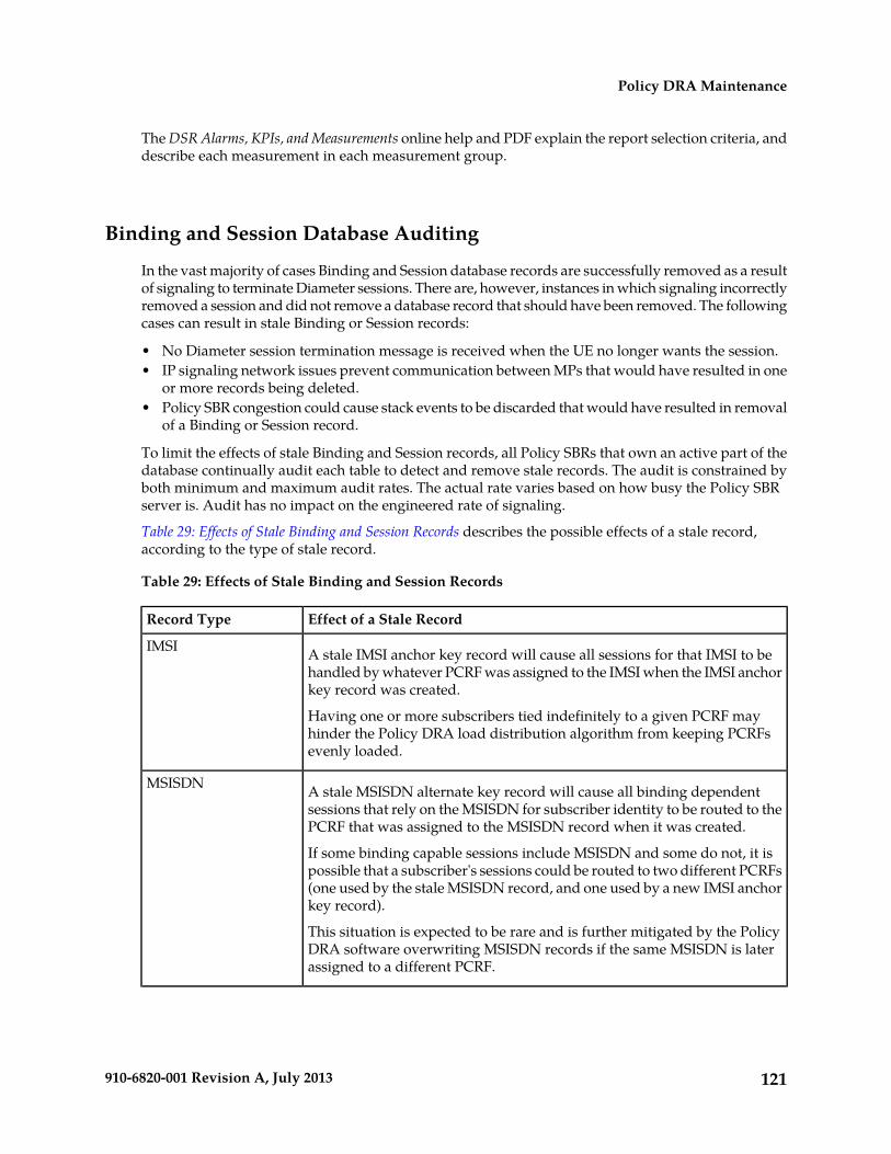
The DSR Alarms, KPIs, and Measurements online help and PDF explain the report selection criteria, anddescribe each measurement in each measurement group.
Binding and Session Database Auditing
In the vast majority of cases Binding and Session database records are successfully removed as a resultof signaling to terminate Diameter sessions. There are, however, instances in which signaling incorrectlyremoved a session and did not remove a database record that should have been removed. The followingcases can result in stale Binding or Session records:
• No Diameter session termination message is received when the UE no longer wants the session.• IP signaling network issues prevent communication between MPs that would have resulted in one
or more records being deleted.• Policy SBR congestion could cause stack events to be discarded that would have resulted in removal
of a Binding or Session record.
To limit the effects of stale Binding and Session records, all Policy SBRs that own an active part of thedatabase continually audit each table to detect and remove stale records. The audit is constrained byboth minimum and maximum audit rates. The actual rate varies based on how busy the Policy SBRserver is. Audit has no impact on the engineered rate of signaling.
Table 29: Effects of Stale Binding and Session Records describes the possible effects of a stale record,according to the type of stale record.
Table 29: Effects of Stale Binding and Session Records
Effect of a Stale RecordRecord Type
A stale IMSI anchor key record will cause all sessions for that IMSI to behandled by whatever PCRF was assigned to the IMSI when the IMSI anchorkey record was created.
IMSI
Having one or more subscribers tied indefinitely to a given PCRF mayhinder the Policy DRA load distribution algorithm from keeping PCRFsevenly loaded.
A stale MSISDN alternate key record will cause all binding dependentsessions that rely on the MSISDN for subscriber identity to be routed to thePCRF that was assigned to the MSISDN record when it was created.
MSISDN
If some binding capable sessions include MSISDN and some do not, it ispossible that a subscriber's sessions could be routed to two different PCRFs(one used by the stale MSISDN record, and one used by a new IMSI anchorkey record).
This situation is expected to be rare and is further mitigated by the PolicyDRA software overwriting MSISDN records if the same MSISDN is laterassigned to a different PCRF.
121910-6820-001 Revision A, July 2013
Policy DRA Maintenance
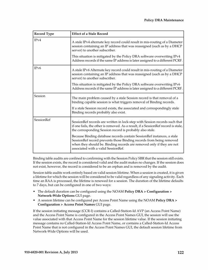
Effect of a Stale RecordRecord Type
A stale IPv4 alternate key record could result in mis-routing of a Diametersession containing an IP address that was reassigned (such as by a DHCPserver) to another subscriber.
IPv4
This situation is mitigated by the Policy DRA software overwriting IPv4Address records if the same IP address is later assigned to a different PCRF.
A stale IPv6 Alternate key record could result in mis-routing of a Diametersession containing an IP address that was reassigned (such as by a DHCPserver) to another subscriber.
IPv6
This situation is mitigated by the Policy DRA software overwriting IPv6Address records if the same IP address is later assigned to a different PCRF.
The main problem caused by a stale Session record is that removal of abinding capable session is what triggers removal of Binding records.
Session
If a stale Session record exists, the associated and correspondingly staleBinding records probably also exist.
SessionRef records are written in lock-step with Session records such thatif one fails, the other is removed. As a result, if a SessionRef record is stale,the corresponding Session record is probably also stale.
SessionRef
Because Binding database records contain SessionRef instances, a staleSessionRef record prevents those Binding records from being removedwhen they should be. Binding records are removed only if they are notassociated with a valid SessionRef.
Binding table audits are confined to confirming with the Session Policy SBR that the session still exists.If the session exists, the record is considered valid and the audit makes no changes. If the session doesnot exist, however, the record is considered to be an orphan and is removed by the audit.
Session table audits work entirely based on valid session lifetime. When a session is created, it is givena lifetime for which the session will be considered to be valid regardless of any signaling activity. Eachtime an RAA is processed, the lifetime is renewed for a session. The duration of the lifetime defaultsto 7 days, but can be configured in one of two ways:
• The default duration can be configured using the NOAM Policy DRA > Configuration >Network-Wide Options GUI page.
• A session lifetime can be configured per Access Point Name using the NOAM Policy DRA >Configuration > Access Point Names GUI page.
If the session initiating message (CCR-I) contains a Called-Station-Id AVP (an Access Point Name)and the Access Point Name is configured in the Access Point Names GUI, the session will use thevalue associated with that Access Point Name for the session lifetime value. If the session initiatingmessage contains no Called-Station-Id Access Point Name, or contains a Called-Station-Id AccessPoint Name that is not configured in the Access Point Names GUI, the default session lifetime fromNetwork-Wide Options will be used.
122910-6820-001 Revision A, July 2013
Policy DRA Maintenance
If the audit discovers a session record for which the current time minus the last touched time (eitherwhen the session was created, or when the last RAA was processed, whichever is more recent) exceedsthe applicable session lifetime, the record is considered to be stale. Stale records are scheduled forPolicy DRA initiated RAR messages to query the policy client that created the session to ask if thesession is still valid.
Generally, Policy SBR servers are engineered to run at 80% of maximum capacity. The audit ispre-configured to run within the 20% of remaining capacity. Audit will yield to signaling. Audit canuse the upper 20% only if signaling does not need it.
The maximum audit rate is configurable (with a default of 12,000) so that the audit maximum rate canbe tuned according to the customer's traffic levels. For example, if the Policy SBR servers are usingonly 50% capacity for signaling, a higher rate could be made available to audit.
If the Policy SBR signaling load plus the audit load cause a Policy SBR server to exceed 100% capacity,that Policy SBR server will report congestion, which will cause an automatic suspension of auditing.Audit will continue to be suspended until no Policy SBR server is reporting congestion. Any PolicySBR on which audit is suspended will have minor alarm 22715 to report the suspension. The alarm iscleared only when congestion abates.
A Policy SBR server determines that it is in congestion by examining the rate of incoming stack events.
• Local congestion refers to congestion at the Policy SBR server that is walking through Binding orSession table records.
• Remote congestion refers to congestion at one of the Session Policy SBR servers that a BindingPolicy SBR server is querying for the existence of session data (using sessionRef).
A Binding Policy SBR server will suspend audit processing if the server on which it is running iscongested (local congestion), or if any of the Session Policy SBR servers to which it is connected throughComAgent connections have reported congestion (remote congestion). Audit processing will remainsuspended until both local congestion and all instances of remote congestion have abated.
A Session Policy SBR server will suspend audit processing if the server on which it is running iscongested (local congestion). The Session Policy SBR does not have to worry about remote congestionbecause it does not rely on binding data to perform its auditing function. Recall that session recordsare removed by audit if they are determined to be stale and the policy client that created the sessionindicates that the session is no longer needed (or if the session integrity feature has exhausted allattempts to communicate with a policy client that created a session). Session auditing will remainsuspended until the local congestion abates.
When a Policy SBR server starts up (i.e. Policy SBR process starts), or when a Policy SBR's audit resumesfrom being suspended, the audit rate ramps up using an exponential slow-start algorithm. The auditrate starts at 1500 records per second and is doubled every 10 seconds until the configured maximumaudit rate is reached.
In addition to the overall rate of record auditing described above, the frequency at which a given tableaudit can be started is also controlled. This is necessary to avoid needless frequent auditing of thesame records when tables are small and can be audited quickly. A given table on a Policy SBR serverwill be audited no more frequently than once every 10 minutes.
In order to have some visibility into what the audit is doing, the audit generates Event 22716 " PolicySBR Audit Statistics Report" with audit statistics at the end of each pass of a table. The format of thereport varies depending on which table the audit statistics are being reported for. The audit reportsfor each table type are formatted as described in Table 30: Audit Report Formats.
123910-6820-001 Revision A, July 2013
Policy DRA Maintenance
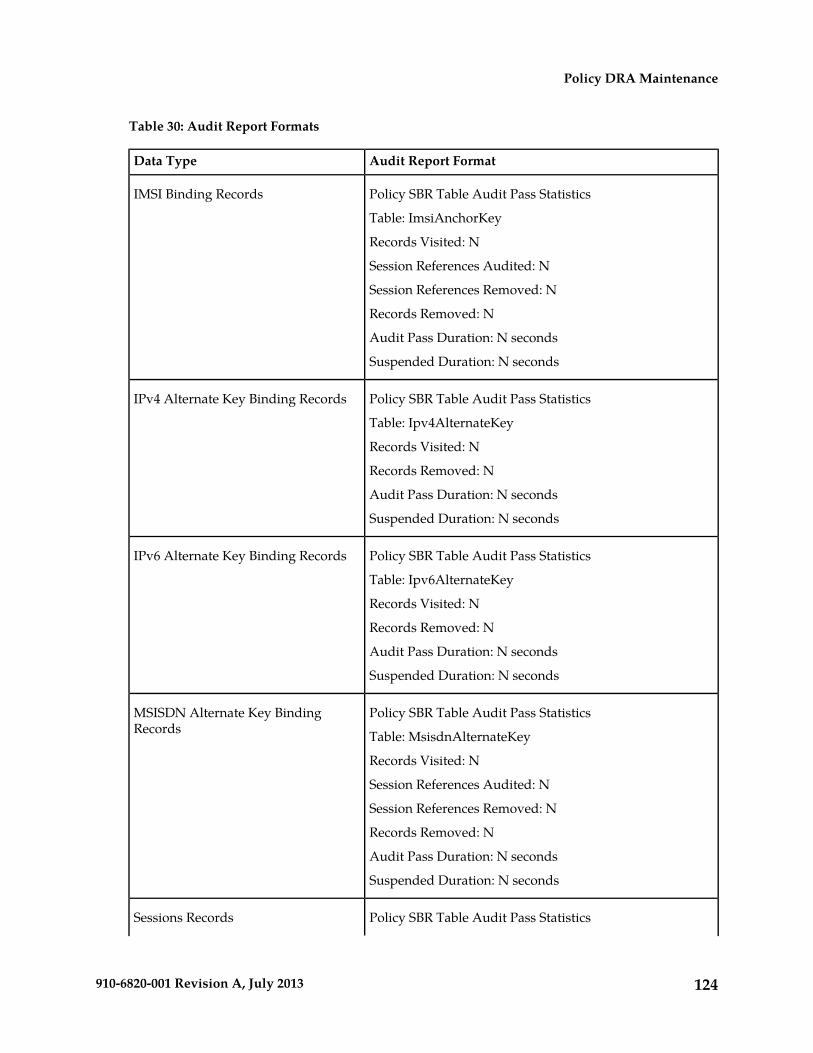
Table 30: Audit Report Formats
Audit Report FormatData Type
Policy SBR Table Audit Pass StatisticsIMSI Binding Records
Table: ImsiAnchorKey
Records Visited: N
Session References Audited: N
Session References Removed: N
Records Removed: N
Audit Pass Duration: N seconds
Suspended Duration: N seconds
Policy SBR Table Audit Pass StatisticsIPv4 Alternate Key Binding Records
Table: Ipv4AlternateKey
Records Visited: N
Records Removed: N
Audit Pass Duration: N seconds
Suspended Duration: N seconds
Policy SBR Table Audit Pass StatisticsIPv6 Alternate Key Binding Records
Table: Ipv6AlternateKey
Records Visited: N
Records Removed: N
Audit Pass Duration: N seconds
Suspended Duration: N seconds
Policy SBR Table Audit Pass StatisticsMSISDN Alternate Key BindingRecords Table: MsisdnAlternateKey
Records Visited: N
Session References Audited: N
Session References Removed: N
Records Removed: N
Audit Pass Duration: N seconds
Suspended Duration: N seconds
Policy SBR Table Audit Pass StatisticsSessions Records
124910-6820-001 Revision A, July 2013
Policy DRA Maintenance
Table: Session
Records Visited: N
Records Requiring a Policy Client Query: N
Records Removed due to Policy Client Query Results: N
Stale Binding Dependent Records Removed: N
Audit Pass Duration: N seconds
Suspended Duration: N seconds
Policy SBR Table Audit Pass StatisticsSession Reference Records
Table: SessionRef
Records Visited: N
Records Removed: N
Audit Pass Duration: N seconds
Suspended Duration: N seconds
Overload Management
The Policy DRA application provides mechanisms to manage the overload and congestion that canoccur on the Policy DRA and Policy SBR. The Policy DRA might receive ingress messages at a ratehigher than the engineered capacity. The internal queues on the Policy DRA might experience higherutilization level than configured. The same might happen on the Policy SBR servers, directly orindirectly resulting from the overloaded traffic from the network or from the Policy DRA.
Overload Controls
The Policy SBRs that implement the Session and Binding databases must protect themselves frombecoming so overloaded that they cease to perform their function. There are two parts to achievingthis goal:
• Detecting the overload condition and severity• Shedding work to reduce load.
Policy DRA DA-MP Overload Control
The number of ingress messages (both Requests and Answers) per second received by Policy DRA iscounted as input to Policy DRA ingress message processing capacity. The capacity is an engineeringnumber of ingress messages per second processed by Policy DRA. The number of Request messagesreceived at Policy DRA per second is also measured separately.
Policy DRA defines alarms on the queue utilization levels based on configured threshold values.Thresholds (in percentage) are configured in association with the Policy DRA ingress message capacity.If the ingress message rate received at Policy DRA exceeds the configured percentage of the maximum
125910-6820-001 Revision A, July 2013
Policy DRA Maintenance
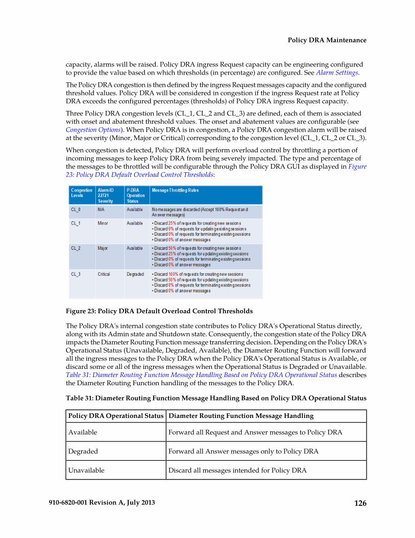
capacity, alarms will be raised. Policy DRA ingress Request capacity can be engineering configuredto provide the value based on which thresholds (in percentage) are configured. See Alarm Settings.
The Policy DRA congestion is then defined by the ingress Request messages capacity and the configuredthreshold values. Policy DRA will be considered in congestion if the ingress Request rate at PolicyDRA exceeds the configured percentages (thresholds) of Policy DRA ingress Request capacity.
Three Policy DRA congestion levels (CL_1, CL_2 and CL_3) are defined, each of them is associatedwith onset and abatement threshold values. The onset and abatement values are configurable (seeCongestion Options). When Policy DRA is in congestion, a Policy DRA congestion alarm will be raisedat the severity (Minor, Major or Critical) corresponding to the congestion level (CL_1, CL_2 or CL_3).
When congestion is detected, Policy DRA will perform overload control by throttling a portion ofincoming messages to keep Policy DRA from being severely impacted. The type and percentage ofthe messages to be throttled will be configurable through the Policy DRA GUI as displayed in Figure23: Policy DRA Default Overload Control Thresholds:
Figure 23: Policy DRA Default Overload Control Thresholds
The Policy DRA's internal congestion state contributes to Policy DRA's Operational Status directly,along with its Admin state and Shutdown state. Consequently, the congestion state of the Policy DRAimpacts the Diameter Routing Function message transferring decision. Depending on the Policy DRA'sOperational Status (Unavailable, Degraded, Available), the Diameter Routing Function will forwardall the ingress messages to the Policy DRA when the Policy DRA's Operational Status is Available, ordiscard some or all of the ingress messages when the Operational Status is Degraded or Unavailable.Table 31: Diameter Routing Function Message Handling Based on Policy DRA Operational Status describesthe Diameter Routing Function handling of the messages to the Policy DRA.
Table 31: Diameter Routing Function Message Handling Based on Policy DRA Operational Status
Diameter Routing Function Message HandlingPolicy DRA Operational Status
Forward all Request and Answer messages to Policy DRAAvailable
Forward all Answer messages only to Policy DRADegraded
Discard all messages intended for Policy DRAUnavailable
126910-6820-001 Revision A, July 2013
Policy DRA Maintenance
Policy SBR Congestion
Policy SBR relies on ComAgent for resource monitoring and overload control. The ComAgent ResourceMonitoring and Overload Framework monitors local MP’s resource utilizations, defines MP congestionbased on one or multiple resource utilizations, communicates the MP congestion levels to Peers, andreports local MP congestion level to the local application (Policy SBR).
Messages called "stack events" are used for communication to and from ComAgent.
ComAgent defines MP congestion levels based on a CPU utilization metric and ingress stack eventrate (number of stack events received per second at local ComAgent), whichever is higher than thepre-defined congestion threshold, and broadcasts the MP congestion state to all its Peers. ComAgentprovides APIs that the local Policy SBR can call for receiving congestion level notifications.
Policy SBR congestion is measured based on the Policy SBR CPU utilization level. There are four PolicySBR congestion levels: CL0 (normal), CL1 (Minor), CL2 (Major) and CL3 (Critical). There are relatedOnset and Abatement threshold values, and Abatement time delays.
The Policy SBR congestion state (CPU utilization) is managed and controlled by the ComAgents onboth Policy DRA and Policy SBR MPs based on the ComAgent MP Overload Management Framework.Messages to a Policy SBR from a Policy DRA are handled based on the congestion state of the PolicySBR. A Policy SBR congestion alarm will be raised when MP congestion notification is received fromComAgent. The appropriate alarm severity information will be included in the notification. The alarmwill be cleared if the congestion level is changed to Normal, also indicated in the notification fromComAgent.
In order to manage the overload situation on a Policy SBR, all stack event messages are associatedwith pre-defined priorities. Before a stack event message is sent, its priority will be compared withthe congestion level of the Policy SBR to which the stack event is sent. If the priority is higher than orequal to the Policy SBR current congestion level, the message will be forwarded. Otherwise, it will bediscarded.
The stack events may also be routed from a Policy SBR to another Policy SBR in some scenarios. Thecongestion control in this case should be conducted based on the congestion state of the receivingPolicy SBR, i.e. the ComAgent on the sending Policy SBR is responsible to compare the stack eventpriority with the congestion level of the receiving Policy SBR and make the routing decision accordingly.
Load Shedding
After the Policy SBR has determined that it is in overload (CL1 – CL3), it informs ComAgent that itsresources and sub-resources are in congestion. ComAgent then broadcasts this information to all ofthe resource users for the specified resources and sub-resources. The resource users now begin to shedload by sending only certain requests for database updates. The resource users determine whichdatabase requests to discard based on the current congestion level of the resource provider.
Database requests are delivered to Policy SBRs using ComAgent stack events. Each stack event has apriority. The resource user software (on either DA-MPs or Policy SBRs) sets the stack event priorityfor every Stack Event it sends, depending on the type of stack event and the circumstances underwhich the Stack Event is being used. For example, the same stack event may be used for signaling andfor audit, but may have a different priority in each circumstance. The Stack Event priority is comparedwith the congestion level of the server that is the target of the stack event to determine whether stackevent should be sent, as shown in Table 32: Stack Event Load Shedding.
127910-6820-001 Revision A, July 2013
Policy DRA Maintenance

Table 32: Stack Event Load Shedding
DescriptionCongestion Level
The resource provider is not congested. No load shedding occurs. Send allStack Events.
CL0
Minor congestion. Auditing is suspended. Send all Stack Events not relatedto auditing.
CL1
Major congestion. No new bindings or sessions are created. Existingbindings and sessions are unaffected. Send only Stack Events related toexisting sessions.
CL2
Critical congestion. Send only Stack Events already started and Stack Eventsthat remove sessions or bindings.
CL3
Shutdown
DA-MP- The Policy DRA application running on DA-MPs supports the DSR Application Infrastructuregraceful shutdown with 5 seconds grace period. This means that when Policy DRA is Disabled (usingthe Diameter->Maintenance->Applications GUI page), the application will transition to the DegradedOperational Status for 5 seconds to allow in-flight messages to be processed without accepting anynew Requests before transitioning to the Unavailable Operational Status. In the Unavailable status,neither Requests nor Answers are processed by the Policy DRA application.
Policy SBR - Because Policy SBR servers use the Active/Standby/Spare redundancy model, andComAgent supports reliable transactions, there is no need for a graceful shutdown mode. Shutdownof a Policy SBR server will cause a failover to another server in the same Server Group. (The exceptionis if the Server Group only has one server, as might be the case in a small demo system.)
The Policy DRA Operational Status (Unavailable, Degraded and Available) is determined by its AdminState, Congestion Level, and the Shutdown State. The Policy DRA application calculates and maintainsits own operational status and reports it to the Diameter Routing Function.
When the Policy DRA application is not processing requests (in Operational Status of Degraded orUnavailable), the Diameter Routing Function will attempt to route new Requests using the rules inthe Peer Routing Tables. If the Request has no Destination-Host AVP, as would be the case forsession-initiating Requests, the routing will fail and the Diameter Routing Function will respond witha 3002 DIAMETER_UNABLE_TO_DELIVER Answer.
When a Server is "Stopped" using the Stop function on the Status & Manage -> Server GUI page,Diameter will terminate all Diameter connections by sending a DPR and waiting for the DPA. If allDPAs have not been received within 15 seconds, Diameter begins termination of its layers and queues.If Diameter is still not shut down after another 15 seconds, the process is abruptly terminated.
To properly shut down a Policy DRA DA-MP server,
1. Go to the Diameter -> Maintenance -> Applications GUI page and Disable the Policy DRAapplication.
The Operational Status of the application will transition to Unavailable
128910-6820-001 Revision A, July 2013
Policy DRA Maintenance
2. Go to the Status & Manage -> Server page and Stop the Server's application processes.
After 30 seconds maintenance can proceed as necessary.
Table 33: Policy DRA Operational Status shows an example of the Policy DRA Operational Statusdetermination where the Shutdown mode is Graceful Shutdown. The Shut down and Shutting downin the Operational Reason column indicate the states where the (Graceful) shutdown process has beencompleted (Shut down) and is in progress (Shutting down) respectively. While the Graceful Shutdownis in progress, the Policy DRA continues to process the messages in its queue for a time interval thatis engineering configurable.
Table 33: Policy DRA Operational Status
Operational ReasonOperational StatusShutdown StateCongestion LevelAdmin State
Not initializedUnavailableN/AN/AN/A
Shut downUnavailableFalse0 ,1, 2, 3Disabled
Shutting downDegradedTrue0 ,1, 2, 3Disabled
Normal
Available with CL_1
AvailableN/A0
1
Enabled
Available with CL_22
Congested with CL_3DegradedN/A3Enabled
Policy SBR - Because Policy SBR servers use the Active/Standby/Spare redundancy model, andComAgent supports reliable transactions, there is no need for a graceful shutdown mode. Shutdownof a Policy SBR server will cause a failover to another server in the same Server Group. (The exceptionis if the Server Group only has one server, as might be the case in a small demo system.)
Diameter Maintenance and Status Data for Components, DSR Applications,and DA-MPs
Maintenance and status data is maintained and displayed on the following Diameter > MaintenanceGUI pages for Diameter Configuration components, DSR Applications including Policy DRA, andDA-MPs including those that run the Policy DRA application:
• Route Lists Maintenance - The Diameter > Maintenance > Route Lists page displays informationabout the Route Groups assigned to Route Lists. Route List maintenance and status data ismaintained and merged to the OAMs. The data is derived from the current Operational Status ofRoute Groups assigned to a given Route List. The Operational Status of each Route List determineswhether the Route List can be used for egress routing of Request messages.
• Route Groups Maintenance - The Diameter > Maintenance > Route Groups page displays theconfigured and available capacity for Route Groups and displays information about Peer Nodesor Connections assigned to a Route Group.
This information can be used to determine if changes need to be made to the Peer Node orConnection assignments in a Route Group in order to better facilitate Diameter message routing.Additionally, this information is useful for troubleshooting alarms.
129910-6820-001 Revision A, July 2013
Policy DRA Maintenance

• Peer Nodes Maintenance - The Diameter > Maintenance > Peer Nodes page provides theOperational Status of Peer Node connections, including a Reason for the status.
• Connections Maintenance - The Diameter > Maintenance > Connections page displays informationabout existing connections, including the Operational Status of each connection.
The Diameter > Maintenance > Connections > SCTP Statistics page displays statistics about pathswithin an SCTP connection. Each line on the page represents a path within an SCTP connection.
• Applications Maintenance - The Diameter > Maintenance > Applications page displays status,state, and congestion information about activated DSR Applications. The data is refreshed every10 seconds.
On the Diameter > Maintenance > Applications page, you can change the Admin State of theselected DSR Application to Enabled or Disabled.
• DA-MPs Maintenance - The Diameter > Maintenance > DA-MPs page provides state andcongestion information about Diameter Agent Message Processors.
On the Diameter > Maintenance > DA-MPs page,
• The Peer DA-MP Status tab displays Peer status information for the DA-MPs.• The DA-MP Connectivity tab displays information about connections on the DA-MPs.• The tab for each individual DA-MP displays DA-MP and connection status from the point-of-view
of that DA-MP.
The Diameter > Reports > MP Statistics (SCTP) Reports GUI page displays the Message Processor(MP) SCTP statistics per MP, for all MPs or for a selected set of MPs. Each row shows the statistics forone MP.
Diameter Maintenance is described in more detail in the Diameter and Mediation User Guide and in theDiameter Help.
Backup and Restore for Policy DRA Configuration Data
Because Policy DRA is required to run on a 3-tier OAM topology where some data is mastered at theNOAM and some data is mastered at SOAMs at each site, backup and restore must be performed onthe NOAM and on the SOAMs at each site.
Only configured data is backed up and restored. Dynamic data such as policy sessions and policybindings that is mastered on Policy SBR MP servers is not backed up or restored.
The Policy DRA feature uses the capabilities of the Backup and Restore functions provided by theOAM Status & Manage >Database GUI page, as described in the "Database Backups and Restores"chapter of the DSR Administration Guide.
130910-6820-001 Revision A, July 2013
Policy DRA Maintenance

Glossary#
A DSR architecture consisting of amanagement (NOAM) layer and a
2-tiered DSR Topology
message processor (MP) layer. Thescope of management for is a singleDSR Signaling Network Element.
A DSR architecture consisting of acentralized management layer with
3-tiered DSR Topology
network wide scope (NOAM), anetwork element (also calledsystem) management (SOAM)layer, and message processors(MPs).
3rd Generation Partnership Project.The standards body for wirelesscommunications.
3GPP
A
Authentication, Authorization, andAccounting (Rx Diametercommand)
AAA
Authentication, AuthorizationRequest (Rx Diameter command)
AAR
Application Function (such asP-CSCF)
AF
A subscriber key other than theanchor subscriber key; for example,
Alternate Key
IP addresses or MSISDNs. Bindingcapable interfaces can includealternate subscriber keys. Bindingdependent interfaces (Rx) cannotadd alternate subscriber keys, but
131910-6820-001 Revision A, July 2013
A
they can use them to find abinding.
The main identifier used in theP-DRA network to identify a
Anchor Key
subscriber. The Anchor Key mustbe an IMSI and must be present inall binding capable interfaces (Gx,Gxx, and S9).
Access Point NameAPN
The name identifying a generalpacket radio service (GPRS) bearerservice in a GSM mobile network.See also GSM.
Each Diameter application isuniquely identified by an assigned
Application ID
Application ID that is a mandatory32-bit field in all Diametermessages. Every DiameterApplication (standard-base orvendor-specific) must have aunique Application ID assigned byIANA. Application ID ranges areStandards-based andVendor-specific.
Each Diameter application isuniquely identified by an IANAassigned Application ID that is amandatory 32-bit field in allDiameter messages. TheApplication ID is commonly usedfor screening and routing messagesbetween Diameter Nodes.Diameter Relay Nodes advertisethe reserved Application ID42946967295 (0xffffffff) whenconnecting to Peers during theDiameter Capabilities Exchangeprocedure. Peer-to-Peer Diametermessages such as CER/CEA usethe reserved Application ID “0”.
132910-6820-001 Revision A, July 2013
Glossary
A
A set of conditions that controlmessage routing to a DSR
Application Routing Rule
application based on messagecontent.
Abort-Session-AnswerASA
B
Bearer Binding and EventReporting Function: A type of
BBERF
Policy Client used to control accessto the bearer network (AN).
Gx and Gxx interfaces are capableof creating a binding if no binding
Binding Capable Interface
exists for a subscriber. The CCR-Imessage must include the anchorsubscriber key and may includealternate subscriber keys.
Policy SBR database that holdsnetwork-wide subscriber binding
Binding database
information. Maps subscriber keysto the PCRF that hosts thesubscriber’s policy rules. A givenbinding record is maintained by 3servers in the network: an Activeserver, a Standby server, and aSpare server.
C
Credit Control Answer – InitialCCA-I
Credit Control Answer - TerminateCCA-T
Credit Control Answer - UpdateCCA-U
CCR InitialCCR-I
133910-6820-001 Revision A, July 2013
Glossary
C
A mechanism for assigningApplication IDs and supported
CEX Configuration Set
Vendor IDs to a Local Node or toa Connection.
D
Diameter Agent Message ProcessorDA-MP
A DSR MP (Server Role = MP, ServerGroup Function = DiameterSignaling Router). A localapplication such as CPA canoptionally be activated on theDA-MP. A computer or blade that ishosting a Diameter Signaling RouterApplication.
A device at the edge of the networkthat performs access control.
Diameter Client
Diameter agent that forwardsrequests and responses to other
Diameter Relay Agent
Diameter nodes based onrouting-related AVPs (e.g.,Destination-Realm) and routingtable entries. Since relays do notmake policy decisions, they do notexamine or alter non-routing AVPs.As a result, relays never originatemessages, do not need tounderstand the semantics ofmessages or non-routing AVPs,and are capable of handling anyDiameter application or messagetype.
Destination Routing AddressDRA
Diameter Signaling RouterDSR
A set of co-located MessageProcessors which share commonDiameter routing tables and aresupported by a pair of OAM servers.
134910-6820-001 Revision A, July 2013
Glossary

D
A DSR Network Element mayconsist of one or more Diameternodes.
E
Element Management SystemEMS
The EMS feature consolidatesreal-time element management at asingle point in the signaling networkto reduce ongoing operationalexpenses and network downtimeand provide a higher quality ofcustomer service.
G
Graphical User InterfaceGUI
The term given to that set of itemsand facilities which provide theuser with a graphic means formanipulating screen data ratherthan being limited to characterbased commands.
The Diameter credit control basedinterface between a PCRF and a
Gx
PCEF as defined by 3GPP. Theinterface is used to convey sessioninformation from the PCEF to thePCRF, and in reply the PCRFprovides rule information for thePCEF to enforce.
Short for Gxa and Gxc. TheDiameter credit control based
Gxx
interface between a BBERF and aPCRF, as defined by 3GPP.
I
Internal Management InterfaceIMI
135910-6820-001 Revision A, July 2013
Glossary

I
International Mobile SubscriberIdentity
IMSI
IP Front EndIPFE
A traffic distributor that routes TCPtraffic sent to a target set address byapplication clients across a set ofapplication servers. The IPFEminimizes the number of externallyroutable IP addresses required forapplication clients to contactapplication servers.
M
Measurements, Events, Alarms,and Logs
MEAL
Mobile Station InternationalSubscriber Directory Number
MSISDN
The MSISDN is the network specificsubscriber number of a mobilecommunications subscriber. This isnormally the phone number that isused to reach the subscriber.
N
Network ElementNE
An independent and identifiablepiece of equipment closelyassociated with at least oneprocessor, and within a singlelocation.
Network Management SystemNMS
An NMS is typically a standalonedevice, such as a workstation, thatserves as an interface throughwhich a human network managercan monitor and control thenetwork. The NMS usually has aset of management applications
136910-6820-001 Revision A, July 2013
Glossary

N
(for example, data analysis andfault recovery applications).
Network Operations,Administration, and Maintenance
NOAM
O
Operations, Administration, andMaintenance
OAM
The application that operates theMaintenance and AdministrationSubsystem which controls theoperation of many Tekelec products.
P
Policy and Charging EnforcementFunction
PCEF
Maintains rules regarding asubscriber’s use of networkresources. Responds to CCR andAAR messages. Periodically sendsRAR messages. All policy sessionsfor a given subscriber, originatinganywhere in the network, must beprocessed by the same PCRF.
Policy and Charging Rules FunctionPCRF
The ability to dynamically controlaccess, services, network capacity,and charges in a network.
A Diameter node to which a givenDiameter node has a directtransport connection.
Peer
A set of prioritized Peer RoutingRules that define routing to PeerNodes based on message content.
Peer Route Table
137910-6820-001 Revision A, July 2013
Glossary

P
A set of prioritized Peer RoutingRules that define routing to PeerNodes based on message content.
Peer Routing Table
An OAM configured componentthat defines physical locations. The
Place
Site Place groups the servers at aphysical location. Each server isassociated with exactly one SitePlace.
An OAM configured componentused by P-DRA to group Site Places
Place Association
into Policy DRA Mated Pairs andPolicy DRA Binding Regions.
Policy Diameter Relay Agent. Ascalable, geo-diverse DSR
Policy DRA
application that creates a bindingbetween a subscriber and a PCRF,and routes all policy messages fora given subscriber to the PCRF thatcurrently hosts that subscriber’spolicy rules. Policy DRA is capableof performing Topology Hiding tohide the PCRF from the PolicyClient.
A type of Place Association thatdefines the scope of an instance of
Policy DRA Binding Region
the P-DRA Binding database. In thecontext of the P-DRA network, aregion is all of the sites in theP-DRA network. P-DRA supportsonly one instance of the PolicyBinding Region, meaning that thereis only one Binding database forthe entire P-DRA Network.
A type of Place Association. In thecontext of a P-DRA network, a
Policy DRA Mated Pair
Mated Pair is two P-DRA DSRs that
138910-6820-001 Revision A, July 2013
Glossary

P
are paired for redundancy suchthat if one site fails, the other sitecan take over the failed site’s entireload. A Mated Pair sets the scopeof an instance of the Policy Sessiondatabase.
Policy Session Binding RepositoryPolicy SBR
Peer Route Table or Peer RoutingTable
PRT
R
Re-Authorization Answer (Gx orRx Diameter command)
RAA
Re-Authorization Request (Gx orRx Diameter command)
RAR
A list of Server Groups thatsupport a logical resource.
Resource Domain
S
The S9 Diameter interface includesRx, Gx, and Gxx messages, but
S9
when these messages are usedbetween a visited PCRF and thehome PCRF, the interfaces arecollectively referred to as S9.Defined by 3GPP 29.215 as theinterface between a visited PCRFand a home PCRF. There is nodifference in processing of Rx overS9 versus. Rx not over S9. The S9interface is binding capable for Gxand Gxx only. Rx over S9 is bindingdependent.
For DSR, Session Binding RepositorySBR
139910-6820-001 Revision A, July 2013
Glossary
S
A highly available, distributeddatabase for storing Diametersession binding data.
Simple Network ManagementProtocol.
SNMP
An industry-wide standard protocolused for network management. TheSNMP agent maintains datavariables that represent aspects ofthe network. These variables arecalled managed objects and arestored in a management informationbase (MIB). The SNMP protocolarranges managed objects intogroups.
System Operations,Administration, and Maintenance
SOAM
Session-Termination-AnswerSTA
Session Termination Answer (RxDiameter command)
One of several possible keys thatcan be used to uniquely identify a
Subscriber Key
subscriber. Subscriber Keys aredelivered in the Subscriber-IdDiameter AVP of a CCR-I message.One of the Subscriber Keys isdesignated as an Anchor Key.
PCRF that will be used for thebinding unless an error causes
Suggested PCRF
alternate routing. Avoids the needto update the binding if thesuggested PCRF successfullyanswers the CCR-I.
A Policy DRA IMSI Anchor Keybinding record is considered to be
Suspect Binding
140910-6820-001 Revision A, July 2013
Glossary
S
“suspect” if the last attempt toroute a CCR-I message to thebound PCRF failed with a 3002Error Code response. The conceptof Suspect Binding allows bindingsto be removed after a short periodof time (called the Suspect BindingInterval) from a PCRF that hasbecome unreachable.
T
Target Set AddressTSA
An externally routable IP addressthat the IPFE presents to applicationclients. The IPFE distributes trafficsent to a target set address across aset of application servers.
U
User EquipmentUE
V
Virtual IP AddressVIP
Virtual IP is a layer-3 conceptemployed to provide HA at a hostlevel. A VIP enables two or more IPhosts to operate in an active/standbyHA manner. From the perspectiveof the IP network, these IP hostsappear as a single host.
Visited PCRFV-PCRF
X
External Management InterfaceXMI
External Signaling IP AddressXSI
External Signaling InterfaceXSI
141910-6820-001 Revision A, July 2013
Glossary


